US8196621B2 - Slider valve fitment and collar - Google Patents
Slider valve fitment and collarDownload PDFInfo
- Publication number
- US8196621B2 US8196621B2US11/895,843US89584307AUS8196621B2US 8196621 B2US8196621 B2US 8196621B2US 89584307 AUS89584307 AUS 89584307AUS 8196621 B2US8196621 B2US 8196621B2
- Authority
- US
- United States
- Prior art keywords
- fitment
- valve body
- external
- internal
- collar
- Prior art date
- Legal status (The legal status is an assumption and is not a legal conclusion. Google has not performed a legal analysis and makes no representation as to the accuracy of the status listed.)
- Active, expires
Links
Images


Classifications
- B—PERFORMING OPERATIONS; TRANSPORTING
- B67—OPENING, CLOSING OR CLEANING BOTTLES, JARS OR SIMILAR CONTAINERS; LIQUID HANDLING
- B67D—DISPENSING, DELIVERING OR TRANSFERRING LIQUIDS, NOT OTHERWISE PROVIDED FOR
- B67D1/00—Apparatus or devices for dispensing beverages on draught
- B67D1/0042—Details of specific parts of the dispensers
- B67D1/0081—Dispensing valves
- B67D1/0082—Dispensing valves entirely mechanical
- B—PERFORMING OPERATIONS; TRANSPORTING
- B67—OPENING, CLOSING OR CLEANING BOTTLES, JARS OR SIMILAR CONTAINERS; LIQUID HANDLING
- B67D—DISPENSING, DELIVERING OR TRANSFERRING LIQUIDS, NOT OTHERWISE PROVIDED FOR
- B67D1/00—Apparatus or devices for dispensing beverages on draught
- B67D1/08—Details
- B67D1/12—Flow or pressure control devices or systems, e.g. valves, gas pressure control, level control in storage containers
- B67D1/1277—Flow control valves
- B—PERFORMING OPERATIONS; TRANSPORTING
- B67—OPENING, CLOSING OR CLEANING BOTTLES, JARS OR SIMILAR CONTAINERS; LIQUID HANDLING
- B67D—DISPENSING, DELIVERING OR TRANSFERRING LIQUIDS, NOT OTHERWISE PROVIDED FOR
- B67D3/00—Apparatus or devices for controlling flow of liquids under gravity from storage containers for dispensing purposes
- B67D3/04—Liquid-dispensing taps or cocks adapted to seal and open tapping holes of casks, e.g. for beer
- B—PERFORMING OPERATIONS; TRANSPORTING
- B67—OPENING, CLOSING OR CLEANING BOTTLES, JARS OR SIMILAR CONTAINERS; LIQUID HANDLING
- B67D—DISPENSING, DELIVERING OR TRANSFERRING LIQUIDS, NOT OTHERWISE PROVIDED FOR
- B67D7/00—Apparatus or devices for transferring liquids from bulk storage containers or reservoirs into vehicles or into portable containers, e.g. for retail sale purposes
- B67D7/005—Spouts
- F—MECHANICAL ENGINEERING; LIGHTING; HEATING; WEAPONS; BLASTING
- F16—ENGINEERING ELEMENTS AND UNITS; GENERAL MEASURES FOR PRODUCING AND MAINTAINING EFFECTIVE FUNCTIONING OF MACHINES OR INSTALLATIONS; THERMAL INSULATION IN GENERAL
- F16L—PIPES; JOINTS OR FITTINGS FOR PIPES; SUPPORTS FOR PIPES, CABLES OR PROTECTIVE TUBING; MEANS FOR THERMAL INSULATION IN GENERAL
- F16L29/00—Joints with fluid cut-off means
- F16L29/02—Joints with fluid cut-off means with a cut-off device in one of the two pipe ends, the cut-off device being automatically opened when the coupling is applied
- F—MECHANICAL ENGINEERING; LIGHTING; HEATING; WEAPONS; BLASTING
- F16—ENGINEERING ELEMENTS AND UNITS; GENERAL MEASURES FOR PRODUCING AND MAINTAINING EFFECTIVE FUNCTIONING OF MACHINES OR INSTALLATIONS; THERMAL INSULATION IN GENERAL
- F16L—PIPES; JOINTS OR FITTINGS FOR PIPES; SUPPORTS FOR PIPES, CABLES OR PROTECTIVE TUBING; MEANS FOR THERMAL INSULATION IN GENERAL
- F16L37/00—Couplings of the quick-acting type
- F16L37/28—Couplings of the quick-acting type with fluid cut-off means
- F16L37/38—Couplings of the quick-acting type with fluid cut-off means with fluid cut-off means in only one of two pipe-end fittings
- F16L37/40—Couplings of the quick-acting type with fluid cut-off means with fluid cut-off means in only one of two pipe-end fittings with a lift valve being opened automatically when the coupling is applied
- Y—GENERAL TAGGING OF NEW TECHNOLOGICAL DEVELOPMENTS; GENERAL TAGGING OF CROSS-SECTIONAL TECHNOLOGIES SPANNING OVER SEVERAL SECTIONS OF THE IPC; TECHNICAL SUBJECTS COVERED BY FORMER USPC CROSS-REFERENCE ART COLLECTIONS [XRACs] AND DIGESTS
- Y10—TECHNICAL SUBJECTS COVERED BY FORMER USPC
- Y10T—TECHNICAL SUBJECTS COVERED BY FORMER US CLASSIFICATION
- Y10T137/00—Fluid handling
- Y10T137/0318—Processes
- Y10T137/0402—Cleaning, repairing, or assembling
- Y—GENERAL TAGGING OF NEW TECHNOLOGICAL DEVELOPMENTS; GENERAL TAGGING OF CROSS-SECTIONAL TECHNOLOGIES SPANNING OVER SEVERAL SECTIONS OF THE IPC; TECHNICAL SUBJECTS COVERED BY FORMER USPC CROSS-REFERENCE ART COLLECTIONS [XRACs] AND DIGESTS
- Y10—TECHNICAL SUBJECTS COVERED BY FORMER USPC
- Y10T—TECHNICAL SUBJECTS COVERED BY FORMER US CLASSIFICATION
- Y10T29/00—Metal working
- Y10T29/49—Method of mechanical manufacture
- Y10T29/494—Fluidic or fluid actuated device making
Definitions
- the present inventionrelates to quick-disconnect couplings for the dispensing of liquids and semi-liquids from a collapsible bag. More particularly, the present invention relates to a collar for use with a dispensing connector and a double slider valve fitment for use in a quick-disconnect coupling.
- Many systemsare used for dispensing beverage syrup from a disposable package consisting of a flexible collapsible bag in a corrugated box commonly referred to as a bag-in-box dispensing package.
- these systemsinclude a bag that is provided with a fitment in the form of a spout through which filling and dispensing occurs. It is generally desirable to provide a quick-disconnect coupling between the spout and the service line of the pump or other type of beverage mixing and dispensing system. Such a coupling may be carried on the spout fitment of the bag and will work in conjunction with the service line connector or “probe”, and is commonly called in the art a single-service valve and coupling since it is discarded with the bag when it is emptied. This type of valve opens automatically as the line connector is connected to the spout and closes as it is disconnected therefrom to prevent syrup from draining from the bag.
- Some systemsare dedicated to only one type of currently known service line connection; while others are adapted to be used with various types of service line connectors.
- U.S. Pat. No. 4,445,551(Bond, et al.) teaches a cylindrical tubular valve member having a closed lower end positioned within a spout. Gripping lugs on the valve member are adapted to grip the dispensing connector. For dispensing, the dispensing connector pushes the valve member inwardly so that outlets on the side thereof are open to fluid flow. A seal is produced between the O-ring on the dispensing connector and the valve body.
- U.S. Pat. No. 4,421,146(Bond and Ulm) teaches a dispensing valve assembly for coupling to a service line connector.
- the valve memberhas gripping members that cooperate with the dispensing connector to move the valve between a closed and open position.
- the dispensing connectoralso has a collar for gripping the spout.
- An O-ring on the dispensing connectorprovides a seal with the valve.
- U.S. Pat. No. 6,347,785discloses a universal quick-disconnect coupling and valve.
- the fitmentincludes a generally cylindrical spout for attachment to a container that is capable of mating with a dispensing connector.
- a slidermoves axially within the spout and has a valve within it that moves from a closed position to an open position upon insertion of a dispensing connector into the slider.
- An external support member and clamp about the dispensing connectorhas teeth to engage the flange of an external adapter ring of the spout.
- the dispensing connectoris sealed within the slider by an O-ring which cooperates with an internal adapter sleeve that fits within the slider.
- U.S. Pat. No. 5,031,662(Roethel #1), U.S. Pat. No. 6,779,556 (Roethel #2) and U.S. Pat. No. 6,953,070 (Labinski, et al.) teach a dispensing fitment having a first body secured to a liquid container and forming a first flow passage and a valve assembly connected to this secured body, which has a seal retaining body defining a second flow passage that communicates with an inlet of the first flow passage.
- a resilient seal member located in the second flow passageis resiliently urged into sealing engagement with the inlet to block fluid flow from the second flow passage into the first flow passage.
- the assemblyfurther includes a spout that is slideable within the first body to an inward position where the seal member is moved resiliently away from the inlet to allow fluid flow between the passages.
- the seal retaining bodyis a resilient tubular member transverse to the first flow passage and is made of a resilient (i.e. rubber) material.
- a dispensing connector collarhas grooves for engaging flanges on the first body.
- the dispensing connectorincludes O-rings for sealingly engaging the valve assembly.
- U.S. Pat. No. 5,983,964(Zielinksi, et al.) teaches a dispensing apparatus for coupling between a dispensing connector and the spout of a container so as to permit coupling of a valve sub-assembly housed in the dispensing connector with a single slider valve assembly housed in the spout.
- the apparatusincludes a collar about the dispensing connector and includes sleeves having at least two resilient fingers members. Each finger member has a surface engageable with a flange portion on the outer surface of the spout.
- a collaris releasably slid over an outer surface of the sleeve for constricting the resilient finger members toward a lower end of the sleeve.
- the fingersact to lock the collar relative to the spout.
- the systemprovides a single-handed coupling operation for the collar and spout.
- An O-ring on the probeforms the seal with the valve assembly and an inner O-ring connects with the valve sub-assembly.
- the collardoes not engage the valve assembly housed in the spout.
- U.S. Pat. No. 5,095,962(Lloyd-Davies, et al.) teaches a fluid dispensing device comprising a valve member slideable in the spout of a container.
- the single valve memberis tubular and has an open outer end for receiving a dispensing connector and a closed inner end.
- the valve memberhas openings through its sidewalls. In the closed position of the valve member, opposed shoulders of the valve member and of the spout resist axial movement of the valve member in either direction and interengaged sealing surfaces block fluid flow to the openings.
- the outer end portion of the valve memberis laterally outwardly deflectable and includes protrusions adapted to enter the recess of a dispensing connector and engage the dispensing connector whereby the valve member can be moved between the open and closed position.
- an O-ringIn the dispense position, an O-ring provides a seal between the outside of the dispensing connector and the inner wall of the valve member.
- U.S. Pat. No. 5,697,410(Rutter et al. #1) and U.S. Pat. No. 5,901,761 (Rufter, et al. #2) teach a spout fitment for a liquid container.
- the fitmentincludes a dispensing valve member slideable within the spout of the container.
- a valve element within the slideable dispensing valve memberis resiliently biased to close a fluid flow opening therein.
- the valve elementsits on the inside of a wall extending across the slideable dispensing valve member and a resilient member is required to push the valve element against the inner surface of this wall. Given this arrangement, a snap fit of parts is not possible.
- an O-ring on the dispensing connectorforms a seal with the slideable dispensing valve member.
- the membermay also include a ridge for engaging the O-ring and snapping into an associated groove on the dispensing connector.
- a ridge on a dispensing connector showncan apparently press down on the top edge of the slideable dispensing valve member.
- U.S. Pat. No. 5,680,970(Smith and Tschanen) teach a self-closing dispensing valve comprising a valve housing having a fluid conduit with a valve orifice therethrough and a flow control member within the valve body.
- the flow control memberis displaceable between a closed and open position.
- a plurality of resilient flexible fingersare fixed to either the valve housing or the valve member and are deflected when the valve member is displaced to its open position. The fingers are deflected by a conical camming surface on the valve member when displaced toward the open position.
- the fitmentincludes a spout having an external surface capable of mating with a collar of a dispensing connector.
- An external slideris movable axially within the spout and an internal slider is movable axially within the external slider.
- the internal slideris movable between a closed position that prevents the flow of fluid through the fitment and an open position that allows for the flow of fluid through the fitment.
- the internal slideris adapted to be moved between the closed and open positions by insertion of the dispensing connector into the external slider.
- the internal slideris biased toward the closed position when the dispensing connector is released as a result of temporary deformation of portions of the external slider by the internal slider pressed inwardly by the dispensing connector.
- the internal slidercooperates with the dispensing connector by means of locking lugs on a top edge thereof.
- a dispensing connector collaris disclosed, which may be threaded for threaded engagement with an external surface of the spout. In the dispensing position, O-rings on the dispensing connector sealingly engage with the external and internal slider.
- Johnsonrepresent a significant improvement in the art.
- a component that has a significant inherent resiliencei.e. rubber or a spring
- the entire fitmentis preferably formed of plastic.
- the relatively simple arrangement of partsfacilitates both manufacture of the individual valve components and the assembly of the fitment. There nevertheless remains room in the art for improvement.
- sealing engagement between the dispensing connector and fitmentis provided by the O-ring on the dispensing connector.
- the fitments of the prior artgenerally engage with a dispensing connector via a gripping collar on the outside of the spout.
- the dispensing connectorcould comprise a collar adapted for threadable engagement with a flanged or threaded outside surface of the spout.
- the collaris typically adapted to work with certain spouts.
- the present inventionprovides a fitment assembly comprising: a fitment for attachment to a container for holding and dispensing a fluid and having a generally cylindrical spout attached thereto, the fitment comprising a generally cylindrical external valve body movable to a fixed position within the spout; and a generally cylindrical internal valve body movable axially within the external valve body, the internal valve body movable between a closed position operable to prevent the flow of fluid through the fitment and an open position operable to allow the flow of fluid through the fitment, the internal valve body movable between closed and open positions by insertion of a dispensing connector into the external valve body adjacent the internal valve body, the internal valve body being biased toward the closed position; and a collar for attachment to the dispensing connector and for releasable coupling to the fitment, wherein when coupled to the fitment the collar compressively engages the external valve body to form a seal between the external valve body and the dispensing connector.
- the present inventionprovides a dispensing connector collar for engaging a fitment for attachment to a container for holding and dispensing a fluid
- the fitmentcomprising: a spout; an external valve body axially movable to a fixed position within the spout; and an internal valve body movable axially within the external valve body, the internal valve body movable between a closed position operable to prevent the flow of fluid through the fitment and an open position operable to allow the flow of fluid through the fitment, the internal valve body movable between a closed and an open position by insertion of a dispensing connector into the external valve body adjacent the internal slider, the internal valve body being biased toward the closed position; the collar comprising a collar body for engagement about the dispensing connector, the collar body having a fitment end mateable with the fitment so as to compress the top of the external valve body against the dispensing connector to form a seal.
- the present inventionprovides a connector collar for engaging a valved fitment for a container for holding and dispensing fluid having a spout connected to the container and a valve having at least one slidable component securely positioned within the spout, the connector collar comprising a generally cylindrical collar body for engagement about a dispensing connector, the collar body having a fitment end mateable with the fitment so as to compress the top edge of the at least one slidable component so as to form a seal between the at least one slidable component and the dispensing connector.
- the present inventionprovides a collar for a dispensing connector for engaging a fitment comprising a slideable valve assembly in a threaded spout, the collar comprising: an internally threaded surface for threadably engaging with the spout and a compression flange for compressing the valve assembly against the dispensing connector to form a seal when the internally threaded surface is threadably engaged with the spout.
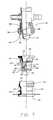
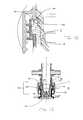
- FIG. 1illustrates an exploded partial cross-sectional side view of a first embodiment of the fitment assembly of the present invention with a dispensing connector.
- FIG. 2illustrates a partial cross-sectional side view of a first embodiment of the fitment assembly of the present invention and a dispensing connector in a pre-cap position.
- FIG. 3illustrates a partial cross-sectional side view of a first embodiment of the fitment assembly of the present invention and a dispensing connector in a fill position.
- FIG. 4illustrates a partial cross-sectional side view of a first embodiment of a fitment assembly of the present invention and a dispensing connector in a full-cap position.
- FIG. 5illustrates a partial cross-sectional side view of a first embodiment of a fitment assembly of the present invention and a dispensing connector in a dispense position.
- FIG. 6illustrates a partial cross-sectional side view of a first embodiment of a fitment assembly of the present invention and a dispensing connector in a reseal and disconnect position.
- FIG. 7Aillustrates a cross-sectional side view of an external valve body used in the fitment assembly of the present invention.
- FIG. 7Billustrates a front elevational view of the external valve body of FIG. 7A .
- FIG. 7Cillustrates a rear elevational view of the external valve body of FIG. 7A .
- FIG. 8Aillustrates a cross-sectional side elevational view of an internal valve body used in the fitment assembly of the present invention.
- FIG. 8Billustrates a front elevational view of an internal valve body of FIG. 8A .
- FIG. 8Cillustrates a rear elevational view of the internal valve body of FIG. 8B .
- FIG. 9illustrates an enlarged view of the sealing points of FIG. 5 .
- FIG. 10illustrates an exploded cross-sectional side view of a second embodiment of the fitment assembly of the present invention with a dispensing connector.
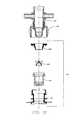
- FIG. 11illustrates a cross-sectional side view of a second embodiment of the fitment assembly of the present invention and a dispensing connector in a pre-cap position.
- FIG. 12illustrates a cross-sectional side view of a second embodiment of a fitment assembly of the present invention and a dispensing connector in a full-cap position.
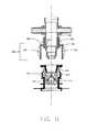
- FIG. 13illustrates a cross-sectional side view of a second embodiment of a fitment assembly of the present invention and a dispensing connector in a probe contact position.
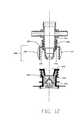
- FIG. 14illustrates a cross-sectional side view of a second embodiment of a fitment assembly of the present invention and a dispensing connector in a dispense position.
- FIG. 15illustrates a cross-sectional side view of a second embodiment of a fitment assembly of the present invention and a dispensing connector in a dispense position and shows the preferred points of sealing.
- FIG. 16illustrates an enlarged view of the sealing points of FIG. 15 .
- a liquid dispensing apparatussuch as is used to dispense individual servings of beverages and the like
- the syrups, flavorings and other ingredientsare frequently supplied in collapsible containers enclosed and shipped within an outer container (“bag-in-box”).
- the shipping package or containeris provided with a fitment that accepts a probe that is part of the dispensing apparatus in order to connect the supply of liquid to the dispensing apparatus.
- the fitmentgenerally contains a valve that is actuated by the insertion of the probe of the dispensing apparatus in order to allow the liquid to flow into the dispensing apparatus.
- the fitment attached to the liquid containeris generally termed a package connector and the probe or similar device on the dispensing apparatus that interacts with the package connector is generally termed a dispensing connector.
- the present inventionincludes a fitment assembly 110 that includes a collar 112 engageable with a dispensing connector 114 and a double slider valve fitment 120 for attachment to a container (not shown) for holding a liquid (not shown).
- the present inventionalso includes the collar 112 of the invention for use with other threaded valve bodies securely slidable within container spouts.
- the collar 112 of the present inventionwill be discussed in the context of fitment assembly 110 , which comprises another embodiment of the present invention.
- the fitment 120comprises a generally cylindrical spout 122 with a generally cylindrical external valve body 124 movable axially within the spout 122 and an internal valve body 126 movable axially within the external valve body 124 .
- generally external valve body 124is slideable to a secured position, while internal valve body 126 is repeatedly slideable to enable opening and closing of the valve.
- the internal valve body 126is movable between a closed position that prevents fluid from flowing through the fitment 120 and an open position that allows fluid to flow from the container through the fitment 120 .
- the internal valve body 126is adapted to be moved between the closed and open positions by insertion of the dispensing connector 114 into the external valve body 124 .
- the internal valve body 126is sized to be received within the external valve body 124 .
- the fitment 120suitably further includes a cap 128 .
- the spout 122is generally cylindrical in shape and one end is received by the collar 112 of the dispensing connector 114 when the assembly is in a dispense position, as will be discussed further below.
- a base portion 130for attaching the spout 122 to a wall of a container (not shown).
- Methods and means for attaching the spout 122 to a wall of a containerare well known in the art and a variety of attachment mechanisms may be used to secure the spout 122 to a container wall, such as by heat sealing or adhesive attachment or both.
- the spout opening 132Located at the opposing end of the spout 122 from the base portion 130 is the spout opening 132 (see FIG. 3 ) which is adapted to receive the dispensing connector 114 therein.
- the internal surface of the spout 122suitably includes an integrally melded stop ridge 133 and sealing rings 135 , both of which serve to limit the motion of the external valve body 124 at certain stages in the functioning of the fitment assembly 110 .
- Suitable stop ridge 133 and sealing rings 135are further described in U.S. Pat. No. 6,347,785 (Copp et al.) the disclosures of which are incorporated herein by reference.
- the external surface 137 of the spout 122preferably includes a series of external threads or flanges, which are adapted to mate with corresponding threads on a dispensing apparatus (not shown) or collar 112 with which a double slider fitment 110 may be used.
- the configuration of the external surface 137 of the spout 122is not particularly restricted and may be altered in accordance with known ways to connect such surfaces e.g. a snap-fit arrangement could also be used. In the embodiment shown in FIGS. 2 through 6 , generally, the configuration of the external surface of the spout is not particularly restricted. In the embodiment shown in FIGS. 9 through 14 , the external surface of the spout is threaded for threaded engagement with a cooperating threaded collar.
- the external valve bodywill be described with reference to FIGS. 2 through 6 and FIGS. 7A , 7 B and 7 C.
- the external valve body 124is generally cylindrically shaped having an external shell 138 that includes a stop ridge 140 at one end and a positioning ring 142 at the opposing end.
- the positioning ring 142is located adjacent the base portion 130 of the spout 122
- the stop ridge 140is located adjacent the spout opening 132 .
- the external surface 138may be engageable with collar 112 , as will be described further below.
- threaded portion 144is threadably engageable with the collar 112 .
- projection 146that extends around the internal circumference of the shell 138 .
- the projection 146has an upper surface 148 that faces the end of the shell 138 containing the stop ridge 140 , and a lower edge 150 that faces the end of the shell 138 containing the positioning ring 142 .
- projection or ledge 146has an inverted “L” shape as shown in the Figures. Extending away from the lower edge 150 towards the end of the shell 138 , which includes the stop ridge 140 , are a series of radially spaced posts 152 defining apertures 153 therebetween. The posts 152 support a valve seat 154 at their lower ends.
- the posts 152extend substantially parallel to the shell 138 of the external valve body 124 and are spaced from the shell 138 such that liquid may flow between the shell 138 and the posts 152 and through the space between each post 152 .
- the valve seat 154is substantially circular and extends between the lower ends of the spaced posts 152 .
- the valve seat 154includes a plurality of spaced projections 158 that extend upwardly from the valve seat 154 towards the projection 146 .
- the projections 158are preferably centrally located on the valve seat 154 and are radially spaced thereon and are operable to be received in the internal valve body 126 as will be described below. It will be understood by a person skilled in the art that the projections 158 may be spaced in any pattern and may form any shape that performs the same function as the projections 158 .
- the internal valve body 126will be described with reference to both FIGS. 2 through 6 and especially FIGS. 8A , 8 B and 8 C.
- Located on the internal valve body 126are a series of ports 164 that allow the passage of fluid therethrough when the internal valve body 126 is in the open position. When in the open position, the ports 164 are in fluid communication with the apertures 153 between the posts 152 of the external valve body 124 .
- the internal valve body 126includes a generally cylindrical body 166 with a base ring 168 that extends around one end of the body 166 , and a top ring 170 that extends outwardly from and around the opposing end of the body 166 from the base ring 168 .
- a central post 174extends away from the body 166 at the opposing end to the base ring 168 , and is operable to engage the dispensing connector 114 , when the fitment 120 is attached to the dispensing connector 114 .
- the body 166is sized to be received within the external valve body 124 extending beyond the projection 146 of the external valve body 124 and operable to abut the valve seat 154 .
- the top ring 170suitably is sized to extend beyond the circumference of the body 166 to rest against and abut the projection 146 when the internal valve body 126 is in the open position. In the open position, the insertion of the dispensing connector 114 moves the internal valve body 126 towards the valve seat 154 and positions the base ring 168 of the body 166 adjacent the valve seat 154 .
- the projections 158 on the valve seat 154are biased inwardly by the internal walls 175 of the body 166 of the internal valve body 126 .
- the internal walls 175 of the body 166are sloped inwardly to bias the projections 158 inwardly when the plug 126 is located adjacent the valve seat 154 .
- the projections 158will return to their normally biased position and flex outwardly.
- the projections 158move outwardly, the internal valve body 126 will be forced away from the valve seat 154 and the internal valve body 126 will return to the closed position.
- Other embodimentsmay be used that force the projections to bend away from their normal position upon insertion of the dispensing connector 114 into the fitment, provided that when the dispensing connector 114 is removed the projections force the internal valve body 126 away from the valve seat 154 to the closed position. While the projections 158 are biased inwardly and then flex to their initial position, the required inherent resilience is fairly limited and all parts of the fitment 120 may be formed of a fairly rigid material.
- the fitment assembly 110 of the present inventionmay be made of any material having suitable properties, preferably, it is made of a synthetic resin material that can be melded to form its parts.
- the synthetic resin materialmust have sufficient resiliency so that the projections 158 will return to their rest position when a deforming pressure is released. If the fitment assembly 110 is made from a single synthetic resin material, recycling of the valve is made particularly easy, because the used valve can be ground up, remelted and remoulded into new valves. It is preferred that the fitment assembly 110 be made from a synthetic resin that is the same as that used to form the liquid-containing bag with which the fitment is used. Such compatibility further increases the ease of recycling the valve.
- a preferred synthetic resin for the valveis polypropylene.
- the valvecan also be made of high-density polyethylene, polystyrene, nylon or the like.
- the closed positionincludes all such positions in which the internal valve body 126 is moved away from the valve seat 154 and where no fluid can pass through the fitment 120 .
- the external valve body 124is operable to move along the inside of the spout 122 in a smooth telescoping movement while maintaining continuous contact with the spout 122 .
- the internal valve body 126is operable to move along the inside of the external valve body 124 in a smooth telescoping movement.
- the internal valve body 126acts like a plug within the external valve body 124 and is seated within the external valve body 124 in the open position to allow fluid to pass through and is unseated in the closed position to prevent fluid from passing through.
- the fitment assembly 110preferably further includes a cap 128 , suitable components of which are shown in more detail in FIGS. 4 and 5 .
- the cap 128may include a cover 176 and a skirt 178 bearing an outer retaining ring 180 and an internal cylinder 182 bearing an inner retaining ring 184 which engages the cap 128 with the external valve body 124 when the cap 128 , external valve body 124 , and internal valve body 126 are removed as a unit in order to fill the container.
- the cap 128may be sized so that if present the skirt 178 can be received within the spout 122 .
- the cap 128may also include a smaller outer skirt 185 sized to sit about the top periphery of spout 122 , when the fitment is capped. While the configuration of the cap 128 is not particularly restricted and is within the purview of a person skilled in the art, an example of a suitable cap 128 is disclosed in U.S. Pat. No. 6,347,785. Other alternative cap configurations will be apparent to persons skilled in the art.
- a collar 112 that engages the external valve body 124 in a compressive fashioncan provide improved sealing and reduced seal failure and otherwise improve the sliding operation of the valve components.
- the collar 112 of the fitment assembly 110 of the present inventioncomprises a generally cylindrical collar body 186 for engagement about the dispensing connector 114 .
- the collar body 186includes a fitment end 188 for engaging the fitment.
- the fitment end 188includes an external descending flange 190 and an internal descending flange 191 connected to the collar body 186 .
- the external descending flange 190 and internal descending flange 191are concentrically arranged and form therebetween a receiving space 192 .
- the collar 112engages with the external valve body 124 in a compressive manner, which operates to improve sealing and operation of the double slider mechanism.
- FIG. 2illustrates a partial cross-sectional side view of the double slider valve fitment 120 in a pre-cap position. In this position, the fitment 120 is removably positioned within the spout 122 , in order to be readily removable for filling of the container directly through an open spout 122 .
- FIG. 3illustrates a partial cross-sectional side view of the double slider valve fitment 120 in a fill position. In this position the external valve body 124 , internal valve body 126 and cap 128 are removed from spout 122 and the container is filled.
- FIG. 4illustrates a partial cross-sectional side view of the double slider valve fitment 120 in a full-cap position. This position is suitable for a filled container ready for delivery to the end-user. In this position, the stop ridge 140 and the positioning ring 142 of the external valve body 124 are engaged with the interior of the spout 122 , so that the double slider valve fitment 120 is securely positioned within the spout 122 . The cap 128 is secured to the fitment 120 .
- FIG. 5illustrates a partial cross-sectional side view of the collar 112 and the double slider valve fitment 120 in a dispense position with the dispensing connector 114 .
- the userremoves the cap 128 , as shown.
- the dispensing connector 114is engaged with the double slider valve fitment 120 .
- the dispensing connector 114moves the valve to an open position.
- collar 112engages with external valve body 124 to provide an additional point of sealing.
- the collar 112is threaded onto the external valve body 124 , it pulls the dispensing connector 114 down into the external valve body 124 where the nose of the dispensing connector 114 come into contact with the internal valve body 126 .
- the threadingthen moves the internal valve body 126 down into the dispensing position where a first seal A and second seal B associated with an O-ring on the dispensing connector 114 are made during this action.
- a compression flange 193 on the collar 112comes into contact with the top of the external valve body 124 .
- the compression flange 193then goes into the inside of the external valve body 124 and as it moves down on the external valve body 124 , thereby compresses the top of the external valve body 124 against the dispensing connector 114 to form a third seal C between the external valve body 124 and the dispensing connector 114 .
- Seal Chas a friction component and, accordingly, the tighter the collar 112 is turned, the tighter the third seal C becomes. While certain embodiments of the compression flange are shown, a compression flange refers to a flange that generally compresses a top edge or portion of the external valve body 124 to form a sealing point against the dispensing connector 114 .
- the collar 112 and the dispensing connector 114apply an inward force on the internal valve body 126 and the internal valve body 126 is moved axially within the external valve body 124 towards the valve seat 154 .
- the top ring 170 of the internal valve body 126rests adjacent the upper surface 148 of the ledge 146 , preventing further axial movement of the internal valve body 126 towards the valve seat 154 . It will be understood by a person skilled in the art that further axial movement of the internal valve body 126 may be prevented by either the top ring 170 abutting the ledge 146 or the position of the valve seat 154 adjacent the internal valve body 126 or by both.
- the base ring 168rests against the valve seat 154 and the projections 158 on the valve seat 154 are biased inwardly by the internal walls 175 of the body 166 of the internal valve body 126 .
- the ports 164 of the internal valve body 126are in fluid communication with the apertures 153 located between the posts 152 on the external valve body 124 , and fluid can flow from the container between the shell 138 and the valve seat 154 through the apertures 153 between the posts 152 and through the ports 164 on the internal valve body 126 , into the dispensing connector 114 .
- FIG. 6illustrates a partial cross-sectional side view of the collar 112 and double slider fitment 120 of the present invention and a dispensing connector 114 in a reseal and disconnect position.
- the dispensing connector 114is removed and the valve moves to a closed position of the fitment 120 .
- the internal valve body 126is received in the external valve body 124 with the top ring 170 spaced from the upper surface 148 of the ledge 146 .
- the base ring 168 of the internal valve body 126abuts against the upper ends of the posts 152 of the external valve body 124 and blocks any flow of fluid through the apertures 153 located between the posts 152 .
- the closed positionprevents any fluid from passing through the fitment 120 into the dispensing connector 114 .
- a portion of the spout 122may be received within the receiving space 192 .
- the receiving space 192suitably has smooth walls, such that the spout 122 does not actively engage with any flanges on the exterior surface of the spout 122 and it can therefore receive spouts of various external configurations.
- the collar 112has been described with reference to a descending flange 190 , suitably there is a plurality of discrete descending flanges positioned about the periphery of the collar body 186 , although the flange 190 may extend about the periphery of the collar body 186 .
- the internal surface of the collar body fitment end 188is suitably threaded and is rotatably engageable with threaded portion 144 of external valve body 124 .
- FIGS. 10 through 16A second embodiment of the invention will now be described with reference to FIGS. 10 through 16 .
- partsare numbered in the two-hundreds and like parts are numbered with like reference numerals in the second and third position.
- the second embodimentworks according to the same mechanism of the first embodiment described above, except as described below.
- the fitment end 288 of collar body 286is mateable with the fitment 220 .
- the fitment end 288comprises an external descending flange 290 and an internal descending flange 291 connected to the periphery of the collar body 286 to form a receiving space 292 which may receive a portion of spout 222 .
- the internal surface of this descending flange 290is threaded for threadably engaging the external surface of spout 222 .
- the dispensing connector 214moves the valve to an open position
- the collar 212engages with external valve body 224 to provide an additional point of sealing.
- the collar 212As the collar 212 is threaded onto the spout 222 , it pulls the dispensing connector 214 down into the external valve body 224 where the nose of the dispensing connector 214 come into contact with the internal valve body 226 . The threading then moves the internal valve body 226 down into the dispensing position where a first seal A and second seal B associated with an O-ring on dispensing connector 214 are made during this action. As the collar 212 starts to reach the end of its stroke, the compression flange 293 on the collar 212 comes into contact with the top of the external valve body 224 .
- the compression flange 293then goes into the inside of the top edge of external valve body 224 as the outside wedge angle 294 on the collar 212 starts to wedge against the lock 295 on the external valve body 224 , thereby compressing the top of the external valve body 224 against the dispensing connector 214 to form a third seal C between the external valve body 224 and the dispensing connector 214 . Accordingly, the tighter the collar 212 is turned, the tighter the third seal C becomes.
- Compressions flanges, 193 and 293furnish a further advantage to the fitment assembly of the present invention.
- known fitmentshave a tendency for the collar and probe to become inadvertently disengaged.
- compression flanges 193 and 293suitably “locks” into a groove typical of probes common in the field, thereby reducing the likelihood of inadvertent collar and probe separation.
- the compression flangeis further secured within the groove thereby further securing the two components together.
Landscapes
- Engineering & Computer Science (AREA)
- Mechanical Engineering (AREA)
- General Engineering & Computer Science (AREA)
- Closures For Containers (AREA)
- Devices For Dispensing Beverages (AREA)
- Quick-Acting Or Multi-Walled Pipe Joints (AREA)
- Feeding And Controlling Fuel (AREA)
Abstract
Description
Fitment assembly 110Collar 112Dispensing connector 114- Double
slider valve fitment 120 Spout 122External valve body 124Internal valve body 126Cap 128Base portion 130Spout opening 132- Stop
ridge 133 - Sealing rings135
- External surface of
spout 137 - External shell of
external valve body 138 - Stop
ridge 140 Positioning ring 142- Threaded
portion 144 Projection 146- Upper surface of
projection 148 - Lower edge of
projection 150 - Radially space posts152
Apertures 153Valve seat 154- Spaced
projections 158 - Ports164
- Generally
cylindrical body 166 Base ring 168Top ring 170Post 174Internal walls 175Cover 176Skirt 178Outer retaining ring 180Internal cylinder 182Internal retaining ring 184Outer descending skirt 185Collar body 186- Collar
body fitment end 188 External descending flange 190Internal descending flange 191- Receiving
space 192 Compression flange 193- Wedge angle194
- Lock195
Claims (10)
Priority Applications (5)
| Application Number | Priority Date | Filing Date | Title |
|---|---|---|---|
| US11/895,843US8196621B2 (en) | 2006-08-28 | 2007-08-28 | Slider valve fitment and collar |
| US29/329,928USD618763S1 (en) | 2006-08-28 | 2008-12-23 | Slider valve fitment |
| US13/469,590US8517061B2 (en) | 2006-08-28 | 2012-05-11 | Process for assembling fitment on to a container |
| US13/469,680US8479785B2 (en) | 2006-08-28 | 2012-05-11 | Slider valve fitment and collar |
| US13/469,551US8578979B2 (en) | 2006-08-28 | 2012-05-11 | Process for dispensing fluid with a slider valve fitment and collar |
Applications Claiming Priority (2)
| Application Number | Priority Date | Filing Date | Title |
|---|---|---|---|
| US84084706P | 2006-08-28 | 2006-08-28 | |
| US11/895,843US8196621B2 (en) | 2006-08-28 | 2007-08-28 | Slider valve fitment and collar |
Related Child Applications (6)
| Application Number | Title | Priority Date | Filing Date |
|---|---|---|---|
| US29/329,920ContinuationUSD601671S1 (en) | 2007-08-28 | 2008-12-23 | Slider valve fitment collar |
| US29/329,928ContinuationUSD618763S1 (en) | 2006-08-28 | 2008-12-23 | Slider valve fitment |
| US29/329,925ContinuationUSD607090S1 (en) | 2007-08-28 | 2008-12-23 | Slider valve fitment probe |
| US13/469,590DivisionUS8517061B2 (en) | 2006-08-28 | 2012-05-11 | Process for assembling fitment on to a container |
| US13/469,551DivisionUS8578979B2 (en) | 2006-08-28 | 2012-05-11 | Process for dispensing fluid with a slider valve fitment and collar |
| US13/469,680ContinuationUS8479785B2 (en) | 2006-08-28 | 2012-05-11 | Slider valve fitment and collar |
Publications (2)
| Publication Number | Publication Date |
|---|---|
| US20080053568A1 US20080053568A1 (en) | 2008-03-06 |
| US8196621B2true US8196621B2 (en) | 2012-06-12 |
Family
ID=39135464
Family Applications (5)
| Application Number | Title | Priority Date | Filing Date |
|---|---|---|---|
| US11/895,843Active2031-01-06US8196621B2 (en) | 2006-08-28 | 2007-08-28 | Slider valve fitment and collar |
| US29/329,928Expired - LifetimeUSD618763S1 (en) | 2006-08-28 | 2008-12-23 | Slider valve fitment |
| US13/469,590ActiveUS8517061B2 (en) | 2006-08-28 | 2012-05-11 | Process for assembling fitment on to a container |
| US13/469,551ActiveUS8578979B2 (en) | 2006-08-28 | 2012-05-11 | Process for dispensing fluid with a slider valve fitment and collar |
| US13/469,680ActiveUS8479785B2 (en) | 2006-08-28 | 2012-05-11 | Slider valve fitment and collar |
Family Applications After (4)
| Application Number | Title | Priority Date | Filing Date |
|---|---|---|---|
| US29/329,928Expired - LifetimeUSD618763S1 (en) | 2006-08-28 | 2008-12-23 | Slider valve fitment |
| US13/469,590ActiveUS8517061B2 (en) | 2006-08-28 | 2012-05-11 | Process for assembling fitment on to a container |
| US13/469,551ActiveUS8578979B2 (en) | 2006-08-28 | 2012-05-11 | Process for dispensing fluid with a slider valve fitment and collar |
| US13/469,680ActiveUS8479785B2 (en) | 2006-08-28 | 2012-05-11 | Slider valve fitment and collar |
Country Status (7)
| Country | Link |
|---|---|
| US (5) | US8196621B2 (en) |
| EP (2) | EP2057403B1 (en) |
| CN (1) | CN101512210B (en) |
| BR (1) | BRPI0716115A2 (en) |
| CA (1) | CA2658445C (en) |
| MX (2) | MX354654B (en) |
| WO (1) | WO2008025145A1 (en) |
Cited By (10)
| Publication number | Priority date | Publication date | Assignee | Title |
|---|---|---|---|---|
| US20120067458A1 (en)* | 2010-09-16 | 2012-03-22 | Fres-Co System Usa, Inc. | Package system with automatic shut-off valve for use with dispensing devices |
| US20120222775A1 (en)* | 2006-08-28 | 2012-09-06 | James Johnson | Slider valve fitment and collar |
| US20130199662A1 (en)* | 2010-02-08 | 2013-08-08 | Ipn Ip B.V. | Refillable liquid product container |
| US20140246455A1 (en)* | 2009-09-14 | 2014-09-04 | Pouch Pac Innovations, Llc | Pouch with a tube spout fitment |
| US20160178103A1 (en)* | 2014-12-20 | 2016-06-23 | Scholle Corporation | Connector apparatus and docking station connection therewtih |
| US9511907B2 (en) | 2014-07-10 | 2016-12-06 | Scholle Ipn Corporation | Spout assembly for a flexible bag |
| US20170137276A1 (en)* | 2014-03-29 | 2017-05-18 | Dürr Somac GmbH | Filling adapter (claw angle adjustment) |
| US9714124B2 (en)* | 2013-06-28 | 2017-07-25 | Liqui-Box Corporation | Cap assembly for slider valve for aseptic packaging |
| US10994912B2 (en)* | 2018-07-20 | 2021-05-04 | Liqui-Box Corporation | Spout-connector assembly (ECHO) |
| US20240158152A1 (en)* | 2021-03-01 | 2024-05-16 | Cocktailsmachine Srl | Connector For A Fluid Dispenser |
Families Citing this family (37)
| Publication number | Priority date | Publication date | Assignee | Title |
|---|---|---|---|---|
| USD601671S1 (en)* | 2007-08-28 | 2009-10-06 | Liqu-Box Corporation | Slider valve fitment collar |
| US8079385B2 (en)* | 2008-04-09 | 2011-12-20 | Liquid Molding Systems, Inc. | Valve assembly |
| USD641832S1 (en)* | 2008-12-29 | 2011-07-19 | Liqui-Box Corporation | Slider valve fitment |
| USD617880S1 (en)* | 2008-12-29 | 2010-06-15 | Liqu-Box Corporation | Slider valve fitment probe |
| US9044584B2 (en)* | 2009-01-06 | 2015-06-02 | Koninklijke Philips N.V. | Pneumatic connector for small-bore medical tubing |
| WO2010080897A1 (en)* | 2009-01-09 | 2010-07-15 | Liqui-Box Corporation | Duckbill flip cap fitment for a collapsible container |
| RU2506486C2 (en)* | 2009-01-09 | 2014-02-10 | Ликви-Бокс Корпорейшн | Closing means with hinged cap and duckbill valve for compressed tank |
| CN101863560B (en)* | 2010-04-08 | 2013-07-31 | 章子三 | Method for digesting activated sludge of strains storage tank |
| USD661786S1 (en)* | 2010-11-12 | 2012-06-12 | Liqui-Box Corporation | Dispensing connector collar with a double barb |
| USD661785S1 (en)* | 2010-11-12 | 2012-06-12 | Liqui-Box Corporation | Dispensing connector collar with a single barb |
| USD661787S1 (en)* | 2010-11-12 | 2012-06-12 | Liqui-Box Corporation | Dispensing connector collar with a double barb and slits |
| US8511639B2 (en) | 2010-11-15 | 2013-08-20 | Liqui-Box Corporation | Adaptor for use with a valve fitment |
| ES2562650T3 (en)* | 2011-03-30 | 2016-03-07 | Liqui-Box Corporation | A discharge adapter for use with a valve assembly assembly for cleaning the assembly |
| BR112014004758A2 (en)* | 2011-08-29 | 2017-03-21 | Liqui-Box Corp | fit for use in a retractable bag and process for filling an unfilled retractable bag |
| WO2013165957A1 (en)* | 2012-04-30 | 2013-11-07 | Liqui-Box Corporation | A tube fitment for use with a valve fitment for dispensing fluids |
| US9604836B2 (en)* | 2012-05-25 | 2017-03-28 | Vitop Moulding S.R.L. | System for the controlled tapping of liquids from containers |
| EP2969804B1 (en)* | 2013-03-15 | 2019-01-16 | Silgan Dispensing Systems Slatersville LLC | Vented closure assembly for a spray container |
| IL229909B (en)* | 2013-12-11 | 2018-07-31 | Neviot Nature Galilee Ltd | Apparatus for closing a fluid container |
| GB201417128D0 (en) | 2014-09-29 | 2014-11-12 | Ds Smith Plastics Ltd | Dispensing assembly |
| EP3307643A4 (en) | 2015-06-12 | 2018-12-19 | Liqui-Box Corporation | Fitment for dispensing fluids from a flexible container |
| USD787650S1 (en)* | 2015-09-08 | 2017-05-23 | Scholle Ipn Corporation | Connector |
| MX2018005466A (en) | 2015-11-02 | 2018-11-09 | Liqui Box Corp | Spout-connector assembly for fluid dispensing from flexible bags. |
| USD803993S1 (en)* | 2016-06-21 | 2017-11-28 | Whirlpool Corporation | Connection component |
| DE102016115389A1 (en)* | 2016-08-19 | 2018-02-22 | Knorr-Bremse Systeme für Nutzfahrzeuge GmbH | Hydraulic connection part and counterpart for a quick connector |
| USD944085S1 (en)* | 2018-01-08 | 2022-02-22 | Scholle Ipn Corporation | Connector |
| CN112423988B (en) | 2018-07-13 | 2022-08-02 | 惠普发展公司,有限责任合伙企业 | Nozzle with inclined clamping flange for printing liquid supply device |
| US11198299B2 (en) | 2018-07-13 | 2021-12-14 | Hewlett-Packard Development Company, L.P. | Collar for fluid barrier |
| EP3687810B1 (en) | 2018-07-13 | 2023-04-12 | Hewlett-Packard Development Company, L.P. | Pliable print liquid supply reservoirs with offset spout |
| EP3687808B1 (en) | 2018-07-13 | 2023-04-12 | Hewlett-Packard Development Company, L.P. | Coupling systems |
| CN112055658B (en) | 2018-07-13 | 2022-06-21 | 惠普发展公司,有限责任合伙企业 | Clamps with wedge-shaped fork ends for printing liquid supplies |
| CN109095429B (en)* | 2018-09-14 | 2024-05-24 | 宁波铭匠扎啤设备有限公司 | Distributor with wine head throttle valve |
| US11639255B2 (en) | 2019-11-20 | 2023-05-02 | Liqui-Box Corporation | Filtering fitment for fluid packaging |
| WO2021207125A2 (en)* | 2020-04-07 | 2021-10-14 | Liqui-Box Corporation | Fitment for dispensing fluids from a flexible container and related applications |
| US11459154B2 (en) | 2020-04-08 | 2022-10-04 | Liqui-Box Corp. | System for preventing blockage of evacuation of flexible packaging |
| US11352244B1 (en)* | 2020-12-03 | 2022-06-07 | John Bean Technologies Corporation | Sanitary fill head |
| CN113294531B (en)* | 2021-06-10 | 2022-11-15 | 上海崇晟精密模塑有限公司 | Screw propulsion deblocking fluid passage mechanism |
| USD1079901S1 (en)* | 2021-10-11 | 2025-06-17 | Turbosmart Pty Ltd | Boost tee |
Citations (19)
| Publication number | Priority date | Publication date | Assignee | Title |
|---|---|---|---|---|
| US4421146A (en) | 1981-11-09 | 1983-12-20 | Liqui-Box Corporation | Quick-disconnect service-line connector and valve assembly |
| US4445539A (en) | 1979-07-19 | 1984-05-01 | The Coca-Cola Company | Dip tube and valve with quick-disconnect coupling for a collapsible container |
| EP0156500A1 (en) | 1984-02-24 | 1985-10-02 | Scholle Corporation | Fluid dispensing assembly |
| US5031662A (en) | 1990-07-20 | 1991-07-16 | The Meyer Company | Adapter coupling for beverage systems |
| US5072756A (en)* | 1991-01-25 | 1991-12-17 | Scholle Corporation | Valve assembly for fluid line connection |
| US5095962A (en) | 1990-08-09 | 1992-03-17 | Scholle Corporation | Beverage dispenser coupling |
| US5255713A (en) | 1992-01-10 | 1993-10-26 | Scholle Corporation | Valve with integral plastic spring for poppet |
| US5680970A (en) | 1994-02-17 | 1997-10-28 | Liqui-Box Corporation | Self closing dispensing valve biased by resilient fingers |
| US5697410A (en) | 1994-09-13 | 1997-12-16 | Packaging Systems, Inc. | Liquid container valve structures for use with service-line connectors |
| US5983964A (en) | 1995-12-05 | 1999-11-16 | Packaging Systems, L.L.C. | Method and apparatus for coupling with a spout |
| CA2371239A1 (en) | 1999-06-04 | 2000-12-14 | Liqui-Box Corporation | Universal quick-disconnect coupling and valve |
| US6561386B1 (en)* | 2002-01-03 | 2003-05-13 | Juice Tyme | Ball check valve assembly |
| US6637725B2 (en)* | 1999-06-04 | 2003-10-28 | Liqui-Box Corporation | Universal quick-disconnect coupling and valve |
| US6702337B2 (en)* | 2000-04-12 | 2004-03-09 | David S. Smith Packaging Ltd. | Spout for screw on connector |
| US6779556B2 (en) | 2001-04-03 | 2004-08-24 | The Meyer Company | Half-tube seal adapter coupling for beverage systems |
| WO2004085283A1 (en) | 2003-03-27 | 2004-10-07 | Liqui-Box Canada Inc. | Double slider valve fitment |
| CA2554832A1 (en) | 2004-02-03 | 2005-08-18 | Liqui-Box Canada Inc. | Threaded spout |
| US6953070B1 (en) | 2003-03-25 | 2005-10-11 | The Meyer Company | Dispenser valve with push-to-open spout |
| US7882977B2 (en)* | 2003-08-01 | 2011-02-08 | Liqui-Box Corporation | Fitment assembly for a container having a tamper indication band attached thereto |
Family Cites Families (12)
| Publication number | Priority date | Publication date | Assignee | Title |
|---|---|---|---|---|
| US3836741A (en)* | 1967-11-06 | 1974-09-17 | Ite Imperial Corp | Adjustable contact nozzle and retractable arcing chamber for gas blast circuit breakers |
| DE4344632A1 (en)* | 1993-12-24 | 1995-06-29 | Putzmeister Maschf | Slide device for a two-cylinder slurry pump |
| USD380525S (en)* | 1994-05-31 | 1997-07-01 | Tetra Laval Holdings & Finance S.A. | Connection piece for milk pipeline valve |
| US5832737A (en)* | 1996-12-11 | 1998-11-10 | American Standard Inc. | Gas actuated slide valve in a screw compressor |
| US5823224A (en)* | 1997-06-26 | 1998-10-20 | Brifer International Ltd. | Slide valve |
| US5884648A (en)* | 1997-08-27 | 1999-03-23 | Scholle Corporation | Coupling valve apparatus and method |
| NL1008658C2 (en)* | 1998-03-20 | 1999-09-21 | Lande En Zonen B V Van De | Gate valve. |
| US5950665A (en)* | 1998-07-01 | 1999-09-14 | Robertshaw Controls Company | Slide valve |
| PL1577592T3 (en)* | 2004-03-15 | 2008-09-30 | Applied Mat Gmbh & Co Kg | Gate valve |
| USD521596S1 (en)* | 2004-08-02 | 2006-05-23 | Pgi International, Ltd. | 5 valve small bore manifold |
| USD521597S1 (en)* | 2004-08-02 | 2006-05-23 | Pgi International, Ltd. | 5 valve large bore manifold |
| CN101512210B (en)* | 2006-08-28 | 2011-03-02 | 利魁包装加拿大有限公司 | Slider valve fitment and collar |
- 2007
- 2007-08-28CNCN2007800323148Apatent/CN101512210B/ennot_activeExpired - Fee Related
- 2007-08-28BRBRPI0716115patent/BRPI0716115A2/ennot_activeIP Right Cessation
- 2007-08-28EPEP07800537.8Apatent/EP2057403B1/enactiveActive
- 2007-08-28CACA2658445Apatent/CA2658445C/enactiveActive
- 2007-08-28MXMX2013008335Apatent/MX354654B/enunknown
- 2007-08-28EPEP16170915.9Apatent/EP3081838A1/ennot_activeWithdrawn
- 2007-08-28USUS11/895,843patent/US8196621B2/enactiveActive
- 2007-08-28WOPCT/CA2007/001512patent/WO2008025145A1/enactiveApplication Filing
- 2007-08-28MXMX2009001545Apatent/MX2009001545A/enactiveIP Right Grant
- 2008
- 2008-12-23USUS29/329,928patent/USD618763S1/ennot_activeExpired - Lifetime
- 2012
- 2012-05-11USUS13/469,590patent/US8517061B2/enactiveActive
- 2012-05-11USUS13/469,551patent/US8578979B2/enactiveActive
- 2012-05-11USUS13/469,680patent/US8479785B2/enactiveActive
Patent Citations (25)
| Publication number | Priority date | Publication date | Assignee | Title |
|---|---|---|---|---|
| US4445539A (en) | 1979-07-19 | 1984-05-01 | The Coca-Cola Company | Dip tube and valve with quick-disconnect coupling for a collapsible container |
| US4421146A (en) | 1981-11-09 | 1983-12-20 | Liqui-Box Corporation | Quick-disconnect service-line connector and valve assembly |
| US4445551A (en) | 1981-11-09 | 1984-05-01 | Bond Curtis J | Quick-disconnect coupling and valve assembly |
| US4421146B1 (en) | 1981-11-09 | 1998-02-17 | Liqui Box Corp | Quick-disconnect service-line connector and valve assembly |
| EP0156500A1 (en) | 1984-02-24 | 1985-10-02 | Scholle Corporation | Fluid dispensing assembly |
| US5031662A (en) | 1990-07-20 | 1991-07-16 | The Meyer Company | Adapter coupling for beverage systems |
| US5095962A (en) | 1990-08-09 | 1992-03-17 | Scholle Corporation | Beverage dispenser coupling |
| US5072756A (en)* | 1991-01-25 | 1991-12-17 | Scholle Corporation | Valve assembly for fluid line connection |
| US5255713A (en) | 1992-01-10 | 1993-10-26 | Scholle Corporation | Valve with integral plastic spring for poppet |
| US5680970A (en) | 1994-02-17 | 1997-10-28 | Liqui-Box Corporation | Self closing dispensing valve biased by resilient fingers |
| US5697410A (en) | 1994-09-13 | 1997-12-16 | Packaging Systems, Inc. | Liquid container valve structures for use with service-line connectors |
| US5901761A (en) | 1994-09-13 | 1999-05-11 | Packaging Systems, L.L.C. | Liquid container valve structures for use with service-line connectors |
| US5983964A (en) | 1995-12-05 | 1999-11-16 | Packaging Systems, L.L.C. | Method and apparatus for coupling with a spout |
| CA2371239A1 (en) | 1999-06-04 | 2000-12-14 | Liqui-Box Corporation | Universal quick-disconnect coupling and valve |
| US6347785B1 (en) | 1999-06-04 | 2002-02-19 | Liqui-Box Corporation | Universal quick-disconnect coupling and valve |
| US6637725B2 (en)* | 1999-06-04 | 2003-10-28 | Liqui-Box Corporation | Universal quick-disconnect coupling and valve |
| US6702337B2 (en)* | 2000-04-12 | 2004-03-09 | David S. Smith Packaging Ltd. | Spout for screw on connector |
| US6779556B2 (en) | 2001-04-03 | 2004-08-24 | The Meyer Company | Half-tube seal adapter coupling for beverage systems |
| US6561386B1 (en)* | 2002-01-03 | 2003-05-13 | Juice Tyme | Ball check valve assembly |
| US6953070B1 (en) | 2003-03-25 | 2005-10-11 | The Meyer Company | Dispenser valve with push-to-open spout |
| WO2004085283A1 (en) | 2003-03-27 | 2004-10-07 | Liqui-Box Canada Inc. | Double slider valve fitment |
| US20040256424A1 (en)* | 2003-03-27 | 2004-12-23 | James Johnson | Double slider valve fitment |
| US7487951B2 (en)* | 2003-03-27 | 2009-02-10 | Liqui-Box Canada Inc. | Double slider valve fitment |
| US7882977B2 (en)* | 2003-08-01 | 2011-02-08 | Liqui-Box Corporation | Fitment assembly for a container having a tamper indication band attached thereto |
| CA2554832A1 (en) | 2004-02-03 | 2005-08-18 | Liqui-Box Canada Inc. | Threaded spout |
Non-Patent Citations (1)
| Title |
|---|
| Corresponding Europen Search Report EP07800537, mailed Jun. 7, 2011. |
Cited By (18)
| Publication number | Priority date | Publication date | Assignee | Title |
|---|---|---|---|---|
| US20120222775A1 (en)* | 2006-08-28 | 2012-09-06 | James Johnson | Slider valve fitment and collar |
| US20120279986A1 (en)* | 2006-08-28 | 2012-11-08 | James Johnson | Process for assembling fitment on to a container |
| US8479785B2 (en)* | 2006-08-28 | 2013-07-09 | Liqui-Box Corporation | Slider valve fitment and collar |
| US8517061B2 (en)* | 2006-08-28 | 2013-08-27 | Liqui-Box Corporation | Process for assembling fitment on to a container |
| US8578979B2 (en) | 2006-08-28 | 2013-11-12 | Liqui-Box Corporation | Process for dispensing fluid with a slider valve fitment and collar |
| US20140246455A1 (en)* | 2009-09-14 | 2014-09-04 | Pouch Pac Innovations, Llc | Pouch with a tube spout fitment |
| US9957148B2 (en)* | 2009-09-14 | 2018-05-01 | Pouch Pac Innovations, Llc | Pouch with a tube spout fitment |
| US20130199662A1 (en)* | 2010-02-08 | 2013-08-08 | Ipn Ip B.V. | Refillable liquid product container |
| US8672000B2 (en)* | 2010-09-16 | 2014-03-18 | Fres-Co System Usa, Inc. | Package system with automatic shut-off valve for use with dispensing devices |
| US20120067458A1 (en)* | 2010-09-16 | 2012-03-22 | Fres-Co System Usa, Inc. | Package system with automatic shut-off valve for use with dispensing devices |
| US9714124B2 (en)* | 2013-06-28 | 2017-07-25 | Liqui-Box Corporation | Cap assembly for slider valve for aseptic packaging |
| US20170137276A1 (en)* | 2014-03-29 | 2017-05-18 | Dürr Somac GmbH | Filling adapter (claw angle adjustment) |
| US10329136B2 (en)* | 2014-03-29 | 2019-06-25 | Dürr Somac GmbH | Filling adapter (claw angle adjustment) |
| US9511907B2 (en) | 2014-07-10 | 2016-12-06 | Scholle Ipn Corporation | Spout assembly for a flexible bag |
| US20160178103A1 (en)* | 2014-12-20 | 2016-06-23 | Scholle Corporation | Connector apparatus and docking station connection therewtih |
| US9605785B2 (en)* | 2014-12-20 | 2017-03-28 | Scholle Ipn Corporation | Connector apparatus and docking station connection therewtih |
| US10994912B2 (en)* | 2018-07-20 | 2021-05-04 | Liqui-Box Corporation | Spout-connector assembly (ECHO) |
| US20240158152A1 (en)* | 2021-03-01 | 2024-05-16 | Cocktailsmachine Srl | Connector For A Fluid Dispenser |
Also Published As
| Publication number | Publication date |
|---|---|
| US20120305590A1 (en) | 2012-12-06 |
| US20120279986A1 (en) | 2012-11-08 |
| US8479785B2 (en) | 2013-07-09 |
| EP2057403B1 (en) | 2016-05-25 |
| EP2057403A4 (en) | 2011-07-06 |
| CN101512210B (en) | 2011-03-02 |
| US8578979B2 (en) | 2013-11-12 |
| MX2009001545A (en) | 2009-04-16 |
| US8517061B2 (en) | 2013-08-27 |
| US20080053568A1 (en) | 2008-03-06 |
| CA2658445C (en) | 2015-06-30 |
| HK1137797A1 (en) | 2010-08-06 |
| USD618763S1 (en) | 2010-06-29 |
| WO2008025145A8 (en) | 2008-04-24 |
| BRPI0716115A2 (en) | 2013-10-01 |
| EP3081838A1 (en) | 2016-10-19 |
| US20120222775A1 (en) | 2012-09-06 |
| CA2658445A1 (en) | 2008-03-06 |
| WO2008025145A1 (en) | 2008-03-06 |
| MX354654B (en) | 2018-03-14 |
| EP2057403A1 (en) | 2009-05-13 |
| CN101512210A (en) | 2009-08-19 |
Similar Documents
| Publication | Publication Date | Title |
|---|---|---|
| US8196621B2 (en) | Slider valve fitment and collar | |
| US10906716B2 (en) | Spout-connector assembly for fluid dispensing from flexible bags | |
| US9862588B2 (en) | Fitment for dispensing fluids from a flexible container | |
| US7487951B2 (en) | Double slider valve fitment | |
| US6637725B2 (en) | Universal quick-disconnect coupling and valve | |
| US5609195A (en) | Two-part coupling structure having cooperating parts effecting fluid flow upon connection and mutual resealing upon disconnection | |
| EP0156500A1 (en) | Fluid dispensing assembly | |
| US6953070B1 (en) | Dispenser valve with push-to-open spout | |
| NZ202381A (en) | Coupling and valve assembly for bag-in-box container | |
| US10994912B2 (en) | Spout-connector assembly (ECHO) | |
| HK1137797B (en) | Slider valve fitment and collar |
Legal Events
| Date | Code | Title | Description |
|---|---|---|---|
| AS | Assignment | Owner name:LIQUI-BOX CANADA INC., CANADA Free format text:ASSIGNMENT OF ASSIGNORS INTEREST;ASSIGNOR:JOHNSON, JAMES;REEL/FRAME:020136/0125 Effective date:20071112 | |
| AS | Assignment | Owner name:LIQUI-BOX CANADA INC., CANADA Free format text:ASSIGNMENT OF ASSIGNORS INTEREST;ASSIGNOR:JOHNSON, JAMES;REEL/FRAME:022289/0639 Effective date:20071112 Owner name:LIQUI-BOX CANADA INC., CANADA Free format text:ASSIGNMENT OF ASSIGNORS INTEREST;ASSIGNOR:JOHNSON, JAMES;REEL/FRAME:022289/0508 Effective date:20071112 Owner name:LIQUI-BOX CANADA INC., CANADA Free format text:ASSIGNMENT OF ASSIGNORS INTEREST;ASSIGNOR:JOHNSON, JAMES;REEL/FRAME:022283/0418 Effective date:20071112 Owner name:LIQUI-BOX CANADA INC., CANADA Free format text:ASSIGNMENT OF ASSIGNORS INTEREST;ASSIGNOR:JOHNSON, JAMES;REEL/FRAME:022283/0041 Effective date:20071112 Owner name:LIQUI-BOX CANADA INC., CANADA Free format text:ASSIGNMENT OF ASSIGNORS INTEREST;ASSIGNOR:JOHNSON, JAMES;REEL/FRAME:022283/0452 Effective date:20071112 | |
| AS | Assignment | Owner name:LIQUI-BOX CORPORATION, OHIO Free format text:ASSIGNMENT OF ASSIGNORS INTEREST;ASSIGNOR:LIQUI-BOX CANADA, INC.;REEL/FRAME:023374/0289 Effective date:20091014 | |
| AS | Assignment | Owner name:BNP PARIBAS, TEXAS Free format text:GRANT OF PATENT SECURITY INTEREST;ASSIGNOR:LIQUI-BOX CORPORATION;REEL/FRAME:027505/0975 Effective date:20111230 | |
| STCF | Information on status: patent grant | Free format text:PATENTED CASE | |
| FEPP | Fee payment procedure | Free format text:PAT HOLDER NO LONGER CLAIMS SMALL ENTITY STATUS, ENTITY STATUS SET TO UNDISCOUNTED (ORIGINAL EVENT CODE: STOL); ENTITY STATUS OF PATENT OWNER: LARGE ENTITY | |
| AS | Assignment | Owner name:LIQUI-BOX CORPORATION, VIRGINIA Free format text:RELEASE BY SECURED PARTY;ASSIGNOR:BNP PARIBAS;REEL/FRAME:036717/0220 Effective date:20151001 | |
| AS | Assignment | Owner name:ANTARES CAPITAL LP, AS AGENT, ILLINOIS Free format text:SECURITY INTEREST;ASSIGNOR:LIQUI-BOX CORPORATION;REEL/FRAME:036776/0672 Effective date:20151001 | |
| FPAY | Fee payment | Year of fee payment:4 | |
| MAFP | Maintenance fee payment | Free format text:PAYMENT OF MAINTENANCE FEE, 8TH YEAR, LARGE ENTITY (ORIGINAL EVENT CODE: M1552); ENTITY STATUS OF PATENT OWNER: LARGE ENTITY Year of fee payment:8 | |
| AS | Assignment | Owner name:ANTARES CAPITAL LP, AS COLLATERAL AGENT, ILLINOIS Free format text:SECURITY INTEREST;ASSIGNOR:LIQUI-BOX CORPORATION;REEL/FRAME:052024/0747 Effective date:20200226 | |
| AS | Assignment | Owner name:LIQUI-BOX CORPORATION, VIRGINIA Free format text:RELEASE BY SECURED PARTY;ASSIGNOR:ANTARES CAPITAL LP, AS AGENT;REEL/FRAME:052054/0001 Effective date:20200226 | |
| AS | Assignment | Owner name:LIQUI-BOX CORPORATION, NORTH CAROLINA Free format text:RELEASE BY SECURED PARTY;ASSIGNOR:ANTARES CAPITAL LP, AS COLLATERAL AGENT;REEL/FRAME:062634/0328 Effective date:20230201 | |
| MAFP | Maintenance fee payment | Free format text:PAYMENT OF MAINTENANCE FEE, 12TH YEAR, LARGE ENTITY (ORIGINAL EVENT CODE: M1553); ENTITY STATUS OF PATENT OWNER: LARGE ENTITY Year of fee payment:12 |