US8196086B2 - Granular channel width for power optimization - Google Patents
Granular channel width for power optimizationDownload PDFInfo
- Publication number
- US8196086B2 US8196086B2US12/840,535US84053510AUS8196086B2US 8196086 B2US8196086 B2US 8196086B2US 84053510 AUS84053510 AUS 84053510AUS 8196086 B2US8196086 B2US 8196086B2
- Authority
- US
- United States
- Prior art keywords
- given cell
- channel width
- cell
- power
- cells
- Prior art date
- Legal status (The legal status is an assumption and is not a legal conclusion. Google has not performed a legal analysis and makes no representation as to the accuracy of the status listed.)
- Active
Links
Images


Classifications
- G—PHYSICS
- G06—COMPUTING OR CALCULATING; COUNTING
- G06F—ELECTRIC DIGITAL DATA PROCESSING
- G06F30/00—Computer-aided design [CAD]
- G06F30/30—Circuit design
- G06F30/39—Circuit design at the physical level
- G—PHYSICS
- G06—COMPUTING OR CALCULATING; COUNTING
- G06F—ELECTRIC DIGITAL DATA PROCESSING
- G06F1/00—Details not covered by groups G06F3/00 - G06F13/00 and G06F21/00
- G06F1/26—Power supply means, e.g. regulation thereof
- G06F1/32—Means for saving power
- G—PHYSICS
- G06—COMPUTING OR CALCULATING; COUNTING
- G06F—ELECTRIC DIGITAL DATA PROCESSING
- G06F2119/00—Details relating to the type or aim of the analysis or the optimisation
- G06F2119/06—Power analysis or power optimisation
Definitions
- the present inventionrelates to integrated circuit design generally and, more particularly, to a method and/or apparatus for implementing a granular channel width for power optimization.
- CMOScomplementary metal-oxide-semiconductor
- ICintegrated circuit
- power consumption in a digital CMOS ICis considered either static (i.e., the power consumption continues regardless of system activity) or dynamic (i.e., the power is only consumed when switching activity occurs).
- Static power consumption in conventional digital CMOS processesis usually the result of transistors that do not act as perfect switches. The transistors are difficult to switch off fully. The transistors remain partially on and thus allow a leakage current to flow. The leakage current results in a continuous waste of power.
- Static power consumptioncan be mitigated by using different switching thresholds for the transistors (i.e., the “Vt” of the transistor).
- Transistors with a higher Vtwill have worse performance (i.e., the transistor is slower to switch on and has less drive current when on). However, transistors with a higher Vt have less power leakage when switched off.
- Multiple libraries with different Vt valuesallow designers to build ICs with targeted performance/power tradeoffs. The multiple libraries are said to be footprint compatible if the libraries are otherwise identical (i.e., pin connections are in the same locations for different Vt versions of the same function).
- the present inventiongenerally concerns a storage medium recording a cell library having one or more cells that may be readable by a computer and may be used by the computer to design an integrated circuit.
- the one or more cellsmay have a physical dimension parameter and a channel width parameter.
- the physical dimension parametermay be a footprint of the one or more cells.
- the channel width parametermay have a minimum driver size and a maximum driver size.
- the channel width parametermay define a range within which a tool varies the channel width between the maximum driver size and the minimum driver size during a design flow of the integrated circuit based upon one or more power criteria without changing the footprint.
- the objects, features and advantages of the present inventionmay include providing a granular channel width for power optimization that may (i) allow a foundry independent approach for using granular channel widths to optimize performance and power, (ii) allow the design of a cell with a maximum driver size, a minimum driver size, and a number of intermediate driver sizes, while generally remaining within Design Rule Check (DRC) parameters, (iii) allow the design of a cell that may be characterized for power and performance at the minimum driver size, maximum driver size, and the intermediate driver sizes, (iv) create a lookup table so that power and performance may be estimated with any final driver size, (v) provide a tool that affords a large granularity of cells across the power and performance spectrum, (vi) remove large step functions in power and performance that prevent Leakage In Place Optimization (LIPO) tools from doing an optimal job, (vii) note information for use in redefining the cell with the appropriate diffusion (OD) area and device width, after the LIPO tool estimates the correct driver size for the best power/performance trade
- FIG. 1is a diagram of example layouts for four cells with Vt and channel length variations
- FIG. 2is a diagram of an example of a 1 ⁇ cell, a 2 ⁇ cell, and a channel width scaled 1 ⁇ cell (based on the 2 ⁇ cell footprint);
- FIG. 3is a diagram of an example of three cells in accordance with a preferred embodiment of the present invention.
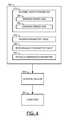
- FIG. 4is a diagram of an example of the structure of a cell
- FIG. 5is a diagram of an example of lookup tables for power parameters and performance parameters of a cell.
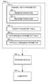
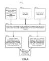
- FIG. 6is a flow chart of a method for optimizing power using a granular channel width in designing an integrated circuit.
- Static power consumptionmay be mitigated by using different transistor channel lengths.
- the librariesmay all be designed to the dimensions of the largest channel length. Libraries may be created that offer several (e.g., three or more) channel length options and/or several (e.g., three or more) Vt options that may have the same footprint to permit power reduction and precise performance/power optimization.
- Each cell (or apparatus) 100 a - 100 dmay implement an inverter cell.
- the cells 100 a - 100 dmay comprise regions (or circuits) 102 , regions (or circuits) 104 , regions (or circuits) 106 , regions (or circuits) 110 , regions (or circuits) 112 , regions (or circuits) 114 , and regions (or circuits) 116 .
- the cells 100 a and 100 bmay comprise regions (or circuits) 108 a .
- the cells 100 c and 100 dmay comprise regions (or circuits) 108 b .
- the cells 100 b and 100 dmay comprise regions (or circuits) 118 .
- the regions 102may be Vdd power traces connected to drain portions of each cell 100 a - 100 d .
- the regions 104may be P+ diffusion regions that establish sources and drains of P-type transistors of each cell 100 a - 100 d .
- the regions 106may be N diffusion well portions of each cell 100 a - 100 d .
- the regions 108 amay be gate portions of each cell 100 a and 100 b .
- the regions 108 bmay be wide gate portions of each cell 100 c and 100 d .
- the regions 110may be gate contact traces connected to the gates 108 a or 108 b of each cell 100 a - 100 d .
- the regions 112may be output terminals of each cell 100 a - 100 d .
- the regions 114may be N+ diffusion regions that establish sources and drains of N-type transistors of each cell 100 a - 100 d .
- the regions 116may be Vss power traces connected to source portions of each cell 100 a - 100 d .
- the regions 118may be Vt implant regions of each cell 100 b and 100 d.
- the cell 100 agenerally illustrates a layout providing a minimum channel length, normal Vt inverter cell.
- the cell 100 bgenerally provides a minimum channel length, high Vt inverter cell with a Vt implant region 118 .
- the cell 100 cgenerally provides an example layout illustrating an extended channel length, normal Vt inverter cell with the wide transistor gate 108 b .
- the cell 100 dgenerally provides an example layout illustrating an extended channel length, high Vt inverter cell with the wide transistor gate 108 b and Vt implant region 118 .
- Some embodiments of the present inventionmay provide a methodology for defining Granular Channel Width (GCW) devices in normal cells.
- the GCW devicesmay be used to optimize power and performance in integrated circuit designs.
- Some embodimentsalso generally describe a method for automating the definition and use of GCW scaled versions of cells.
- Some embodimentsmay also provide procedures for the definition and creation of GCW cells that may be placed in an existing routed chip level database. The GCW cells may be used to maximize static and/or dynamic power recovery.
- Transistor sizesmay be built into the cell libraries that IC designers use.
- the design toolsmay optimize performance while minimizing power.
- the performance specifications for a particular applicationoften suggest a choice of a functional cell that uses smaller transistors.
- the performance specificationsmay also include a reduced area for the cells.
- Cell librariesmay define a P-channel transistor and an N-channel transistor of a unit size (e.g., the size of a 1 ⁇ standard inverter). Multiple transistors in parallel may be utilized to gain more drive strength (e.g., performance). Cells that use smaller transistors may often be implemented by using fewer parallel transistors.
- Smaller drive cellsmay be implemented by reducing the channel width instead of the number of parallel transistors. If the libraries generally are otherwise identical, (e.g., the physical dimensions may be similar and the pin connections may be in the same locations for different channel widths) the libraries generally are said to be “footprint compatible”. Footprint compatible cells may be easily swapped anywhere, up to and including the last stages of the design flow to meet performance and power goals.
- the cell (or apparatus) 140may be a 1 ⁇ drive inverter cell.
- the cell (or apparatus) 160may be a 2 ⁇ drive inverter cell.
- the cell (or apparatus) 180may be a 1 ⁇ drive inverter cell.
- the cell 140may comprise a region (or circuit) 142 , a region (or circuit) 144 , a region (or circuit) 146 , a region (or circuit) 148 , a region (or circuit) 150 , a region (or circuit) 152 , a region (or circuit) 154 and a region (or circuit) 156 .
- the region 142may be a Vdd power trace connected to a drain portion of the cell 140 .
- the region 144may be a P+ diffusion region that establishes a source and a drain of a P-type transistor of the cell 140 .
- the region 146may be an N diffusion well portion of the cell 140 .
- the region 148may be a gate portion of the cell 140 .
- the region 150may be a gate contact connected to the gate portion 148 of the cell 140 .
- the region 152may be an output terminal of the cell 140 .
- the region 154may be an N+ diffusion region that establishes a source and a drain of an N-type transistor of the cell 140 .
- the region 156may be a Vss power trace connected to a source portion of the cell 140 .
- the cell 160may comprise a region (or circuit) 162 , a region (or circuit) 164 , a region (or circuit) 166 , a region (or circuit) 168 , a region (or circuit) 170 , a region (or circuit) 172 , a region (or circuit) 174 and a region (or circuit) 176 .
- the region 162may be a Vdd power trace connected to a drain portion of the cell 160 .
- the region 164may be a P+ diffusion region that establishes a source and a drain of a P-type transistor of the cell 160 .
- the region 166may be an N diffusion well portion of the cell 160 .
- the region 168may be a gate portion of the cell 160 .
- the region 170may be a gate contact connected to the gate portion 168 of the cell 160 .
- the region 172may be an output terminal of the cell 160 .
- the region 174may be an N+ diffusion region that establishes a source and a drain of an N-type transistor of the cell 160 .
- the region 176may be a Vss power trace connected to a source portion of the cell 160 .
- the cell 180generally comprises a channel width scaled 1 ⁇ driver cell based on the footprint of the cell 160 .
- the cell 180may comprise a region (or circuit) 182 , a region (or circuit) 184 , a region (or circuit) 186 , a region (or circuit) 188 , a region (or circuit) 190 , a region (or circuit) 192 , a region (or circuit) 194 and a region (or circuit) 196 .
- the region 182may be a Vdd power trace connected to a drain portion of the cell 180 .
- the region 184may be a P+ diffusion region that establishes sources and drains of P-type transistors of the cell 180 .
- the region 186may be an N diffusion well portion of the cell 180 .
- the region 188may be gate portions of the cell 180 .
- the region 190may be a gate contact connected to the gate portions 188 of the cell 180 .
- the region 192may be an output terminal of the cell 180 .
- the region 194may be an N+ diffusion region that establishes sources and drains of N-type transistors of the cell 180 .
- the region 196may be a Vss power trace connected to source portions of the cell 180 .
- the cell 180illustrates a space above the diffusion region 184 and below the diffusion region 194 .
- the channel width scaled layoutmay have similar performance and leakage characteristics to the cell 140 , but may be footprint compatible (e.g., may have the same physical dimensions and pin locations) to the cell 160 . Therefore, so long as performance and power criteria are generally met, the cell 180 and the cell 160 may be swapped for each other in the layout of the final IC design.
- the cell 250 amay be implemented as a 2 ⁇ drive inverter cell.
- the cell 250 bmay be implemented as a 1.5 ⁇ drive inverter cell based on the cell 250 a footprint.
- the cell 250 cmay be implemented as a 1 ⁇ drive inverter cell based on the cell 250 a footprint.
- the cells 250 a - 250 cmay comprise regions (or circuits) 252 , regions (or circuits) 256 , regions (or circuits) 258 , regions (or circuits) 260 , and regions (or circuits) 264 .
- the cell 250 amay comprise a region (or circuit) 254 a and a region (or circuit) 262 a .
- the cell 250 bmay comprise a region (or circuit) 254 b and a region (or circuit) 262 b .
- the cell 250 cmay comprise a region (or circuit) 254 c and a region (or circuit) 262 c.
- the regions 252may be Vdd power traces connected to drain portions of each cell 250 a - 250 c .
- the regions 254 a - 254 cmay be P+ diffusion regions that establish sources and drains of P-type transistors of each cell 250 a - 250 c .
- the regions 256may be gate portions of each cell 250 a - 250 c .
- the regions 258may be gate contacts connected to the gate portions 256 of each cell 250 a - 250 c .
- the regions 260may be output terminals of each cell 250 a - 250 c .
- the regions 262 a - 262 cmay be N+ diffusion regions that establish sources and drains of N-type transistors of each cell 250 a - 250 c .
- the regions 264may be Vss power traces connected to the source portions of the cells 250 a - 250 c .
- differences between the cells 250 a - 250 cmay be the OD area of the regions 254 a - 254 c and the regions 262 a - 262 c and the resulting power/performance profiles of the cells 250 a - 250 c.
- the cellmay be any one or more of the cells 100 a - 100 d , 140 , 160 , 180 , and/or 250 a - 250 c .
- the structure 300generally comprises a parameter (or criteria) 310 , a parameter (or criteria) 320 , a parameter (or criteria) 330 , a lookup table (or criteria) 340 , a lookup table (or criteria) 350 , and a parameter (or criteria) 360 .
- the structure 300may be associated with a block (or circuit) 362 , and a block (or circuit) 364 .
- the parameter 310may be defined as a channel width parameter of the structure 300 (e.g., the width of regions 254 a and/or 262 a ).
- the parameter 320may be defined as a minimum driver size of the channel width parameter 310 .
- the parameter 330may be defined as a maximum driver size of the channel width parameter 310 .
- the lookup table 340may store the power criteria of the structure 300 .
- the lookup table 350may store the performance criteria (e.g., propagation delay, rise time, fall time, etc.) of the structure 300 .
- the parameter 360may be defined as a physical dimension parameter of the structure 300 .
- the parameter 360generally defines a footprint for the structure 300 .
- the block 362may comprise a non-transitory storage medium.
- the block 364may comprise a computer.
- the structure 300may be defined within a cell library and the cell library may be recorded on the storage medium 362 that may be readable by the computer 364 .
- the structure 300may be used to design an integrated circuit.
- the structure 300may have two or more parameters including, but not limited to, the physical dimension parameter 360 and the channel width parameter 310 .
- the channel width parameter 310may include the maximum driver size 330 and the minimum driver size 320 .
- the channel width of the diffusion regione.g., the diffusion regions 254 a - 254 c and/or 262 a - 262 c ) may be varied between the maximum driver size 330 and the minimum driver size 320 by a tool (e.g., a computer program configured to design integrated circuits).
- the toolmay vary the channel width parameter 310 during a design flow of the integrated circuit based on one or more power criteria of lookup table 340 , one or more performance criteria of lookup table 350 or a combination of both.
- the structure 300may comprise a description that includes one or more power criteria and performance criteria of lookup tables 340 and/or 350 .
- the channel width of the cellmay comprise a diffusion area (OD) which may be varied to meet a drive strength for a particular application.
- the physical dimension parameter 360may comprise a footprint for the structure 300 such that the footprint may remain the same independent of any variation of the channel width of the structure 300 . Since the footprint of the structure 300 may remain the same, the structure 300 may be swapped for a different channel width cell at any point in the design flow. The cell may be swapped before or after the cell has been placed and routed.
- the lookup table 340generally comprises a number of parameters (or criteria) 340 a - 340 n .
- the parameters 340 a - 340 nmay be defined as a plurality of different power criteria that form the lookup table 340 .
- the values of parameters 340 a - 340 nmay be defined in a description of the structure 300 .
- the lookup table 350generally comprises a number of parameters (or criteria) 350 a - 350 n .
- the parameters 350 a - 350 nmay be defined as a plurality of different performance criteria that form the lookup table 350 .
- the values of parameters 350 a - 350 nmay be defined in a description of the structure 300 .
- a design toolmay use the lookup tables 340 and/or 350 to optimize a power usage and/or a performance of the cell.
- the process 400generally comprises a step (or state) 410 , a step (or state) 420 , a step (or state) 430 , a step (or state) 440 , a step (or state) 450 , a step (or state) 460 , and a step (or state) 470 .
- the step 410may copy a Register Transfer Level (RTL) design and timing constraints for high performance targets into one or more design tools.
- the design toolsmay be executed by the computer 364 .
- the step 420may copy cell libraries into the design tools.
- the step 430may copy a list of GCW cells into the design tools.
- the step 440may use the inputs from the steps 410 - 430 for gate-level synthesis, place and route, optimization, and static timing analysis for the high performance target.
- the step 450may change the timing constraints to a low target performance, present the GCW cells to the design tools, and perform a Leakage In Place Optimization (LIPO) flow for the low performance target product.
- the step 460may present the GCW cells to the design tools and perform an LIPO flow for final cell optimization for the high performance target product.
- the step 470may fix the channel widths of the GCW cells according to the cell optimizations determined in the step 450 and/or the step 460 .
- the LIPOmay be a timing driven leakage power reduction process.
- STAStatic Timing Analysis
- the definition of which cells and devices within a cell may be scaled granularly during LIPOmay be a part of the step 420 and the step 430 .
- common combinational gatesmay be candidates for optimization whereas complex flip-flops may not.
- the characterization time of the complex flip-flopsmay be high and the number of devices in which a granular scaling should be allowed may be low (e.g., only the output driver).
- the layoutmay be constructed in accordance with the cells (e.g., 250 a - 250 c ).
- the minimum driver size, maximum driver size and a number of intermediate driver sizesmay be DRC clean.
- a common P:N channel width ratioshould generally be maintained as the OD areas vary. Characterizations may be run on the minimum sizes and the maximum sizes (e.g., cell 250 c and cell 250 a respectively).
- a number of intermediate driver sizesmay be utilized between the minimum driver size and the maximum driver size.
- One or more lookup table modelse.g., lookup tables 340 and/or 350 as illustrated in FIG.
- the data in the lookup tables 340 and/or 350may be guardbanded with margins to account for inaccuracy due to layout stress effect changes while modifying the OD areas.
- the LIPOmay know the scaling information in the lookup tables 340 and/or 350 when LIPO is executed (e.g., by the computer 364 ) in order to determine the best channel width, channel length, and/or threshold voltage for power/performance for each of the GCW scalable cells.
- the product of the LIPOmay be (i) footprint compatible cell swap information for non-GCW cells and (ii) recommended channel widths, channel lengths, and/or threshold voltages for the GCW cells to provide an optimal power/performance tradeoff.
- the methodology described abovemay be used in system-on-a-chip (SOC) development to optimize power/performance toward the end of the design cycle.
- the methodology of the present inventionmay also be used to migrate a high performance design to lower performance targets while maintaining a routed chip level database. Some products may be designed for multiple performance/power targets. As a result, the same software may be used in the final product but the high volume, low performance applications may not be overburdened by the design for the higher performance low volume applications.
- a Read-Channel IC and a Hard-Disk-Controller ICmay call for identical functionality.
- a commercial Enterprise productmay need twice the performance versus a consumer battery-powered notebook product.
- the consideration of the Enterprise product versus the consumer productmay use multiple development efforts.
- Each product marketmay utilize a fixed development cost for a market-targeted product.
- the lower performance applicationmay be forced to carry the extra power overhead induced by the higher performance application.
- GCW cellsa flow may be demonstrated which may allow a single development cost to be leveraged for entry into additional product segments. The resulting optimization using GCW cells may avoid the large Vt type step functions that commonly limit the effectiveness of the LIPO.
- Channel width scaled librariesmay look like libraries using many parallel, small width transistors. However, the use of GCW scaled libraries for multiple product development may provide functionally similar products with different performance/power capabilities. Some embodiments of the present invention may allow dynamic power recovery in addition to static power recovery at the foundry. Some embodiments may also be of interest in 28 nanometer (nm) technology where footprint compatible channel length scaling may be more challenging than in 40 nm technology. Some embodiments may also provide new differentiating capabilities in dynamic power reduction and extended static power reduction. Some embodiments may also add a fine-grained solution to existing LIPO tools. Some embodiments may also extend LIPO and similar tools to allow reduction of dynamic power loss via in-place optimization. Some embodiments may be used in connection with existing products, or may enable multiple-market product development for a small incremental development cost.
- FIGS. 1-6may be implemented using one or more of a conventional general purpose processor, digital computer, microprocessor, microcontroller, RISC (reduced instruction set computer) processor, CISC (complex instruction set computer) processor, SIMD (single instruction multiple data) processor, signal processor, central processing unit (CPU), arithmetic logic unit (ALU), video digital signal processor (VDSP) and/or similar computational machines, programmed according to the teachings of the present specification, as will be apparent to those skilled in the relevant art(s).
- RISCreduced instruction set computer
- CISCcomplex instruction set computer
- SIMDsingle instruction multiple data
- signal processorcentral processing unit
- CPUcentral processing unit
- ALUarithmetic logic unit
- VDSPvideo digital signal processor
- the present inventionmay also be implemented by the preparation of ASICs (application specific integrated circuits), Platform ASICs, FPGAs (field programmable gate arrays), PLDs (programmable logic devices), CPLDs (complex programmable logic device), sea-of-gates, RFICs (radio frequency integrated circuits), ASSPs (application specific standard products) or by interconnecting an appropriate network of conventional component circuits, as is described herein, modifications of which will be readily apparent to those skilled in the art(s).
- ASICsapplication specific integrated circuits
- FPGAsfield programmable gate arrays
- PLDsprogrammable logic devices
- CPLDscomplex programmable logic device
- sea-of-gatesRFICs (radio frequency integrated circuits)
- ASSPsapplication specific standard products
- the elements of the inventionmay form part or all of one or more devices, units, components, systems, machines and/or apparatuses.
- the devicesmay include, but are not limited to, servers, workstations, storage array controllers, storage systems, personal computers, laptop computers, notebook computers, palm computers, personal digital assistants, portable electronic devices, battery powered devices, set-top boxes, encoders, decoders, transcoders, compressors, decompressors, pre-processors, post-processors, transmitters, receivers, transceivers, cipher circuits, cellular telephones, digital cameras, positioning and/or navigation systems, medical equipment, heads-up displays, wireless devices, audio recording, storage and/or playback devices, video recording, storage and/or playback devices, game platforms, peripherals and/or multi-chip modules.
- Those skilled in the relevant art(s)would understand that the elements of the invention may be implemented in other types of devices to meet the criteria of a particular application.
Landscapes
- Engineering & Computer Science (AREA)
- Theoretical Computer Science (AREA)
- Physics & Mathematics (AREA)
- Computer Hardware Design (AREA)
- General Engineering & Computer Science (AREA)
- General Physics & Mathematics (AREA)
- Evolutionary Computation (AREA)
- Geometry (AREA)
- Design And Manufacture Of Integrated Circuits (AREA)
Abstract
Description
Claims (20)
Priority Applications (6)
| Application Number | Priority Date | Filing Date | Title |
|---|---|---|---|
| US12/840,535US8196086B2 (en) | 2010-07-21 | 2010-07-21 | Granular channel width for power optimization |
| TW100125423ATW201216104A (en) | 2010-07-21 | 2011-07-19 | Granular channel width for power optimization |
| JP2011158945AJP5623354B2 (en) | 2010-07-21 | 2011-07-20 | Granular channel width for power optimization |
| EP11174779AEP2418595A3 (en) | 2010-07-21 | 2011-07-21 | Granular channel width for power optimization |
| CN201110205798XACN102346792A (en) | 2010-07-21 | 2011-07-21 | Granular channel width for power optimization |
| KR1020110072482AKR20120010187A (en) | 2010-07-21 | 2011-07-21 | Standing Channel Width for Power Optimization |
Applications Claiming Priority (1)
| Application Number | Priority Date | Filing Date | Title |
|---|---|---|---|
| US12/840,535US8196086B2 (en) | 2010-07-21 | 2010-07-21 | Granular channel width for power optimization |
Publications (2)
| Publication Number | Publication Date |
|---|---|
| US20120023473A1 US20120023473A1 (en) | 2012-01-26 |
| US8196086B2true US8196086B2 (en) | 2012-06-05 |
Family
ID=44674150
Family Applications (1)
| Application Number | Title | Priority Date | Filing Date |
|---|---|---|---|
| US12/840,535ActiveUS8196086B2 (en) | 2010-07-21 | 2010-07-21 | Granular channel width for power optimization |
Country Status (6)
| Country | Link |
|---|---|
| US (1) | US8196086B2 (en) |
| EP (1) | EP2418595A3 (en) |
| JP (1) | JP5623354B2 (en) |
| KR (1) | KR20120010187A (en) |
| CN (1) | CN102346792A (en) |
| TW (1) | TW201216104A (en) |
Cited By (4)
| Publication number | Priority date | Publication date | Assignee | Title |
|---|---|---|---|---|
| US20120221995A1 (en)* | 2011-02-24 | 2012-08-30 | Bruce Zahn | System and method for employing signoff-quality timing analysis information concurrently in multiple scenarios to reduce dynamic power in an electronic circuit and an apparatus incorporating the same |
| US8762922B1 (en)* | 2013-10-13 | 2014-06-24 | Freescale Semiconductor, Inc. | System for reducing leakage power of electronic circuit |
| US8776003B2 (en) | 2012-07-31 | 2014-07-08 | Lsi Corporation | System and method for employing side transition times from signoff-quality timing analysis information to reduce leakage power in an electronic circuit and an electronic design automation tool incorporating the same |
| US20210264093A1 (en)* | 2019-01-16 | 2021-08-26 | Taiwan Semiconductor Manufacturing Co., Ltd. | Leakage analysis on semiconductor device |
Families Citing this family (61)
| Publication number | Priority date | Publication date | Assignee | Title |
|---|---|---|---|---|
| US8856704B2 (en)* | 2010-11-22 | 2014-10-07 | Industry-University Cooperation Foundation Hanyang University | Layout library of flip-flop circuit |
| JP2012243151A (en)* | 2011-05-20 | 2012-12-10 | Toshiba Corp | Chip size estimation device for semiconductor integrated circuit and chip size estimation method for semiconductor integrated circuit |
| US9244880B2 (en) | 2012-08-30 | 2016-01-26 | Netspeed Systems | Automatic construction of deadlock free interconnects |
| US8885510B2 (en) | 2012-10-09 | 2014-11-11 | Netspeed Systems | Heterogeneous channel capacities in an interconnect |
| US8601423B1 (en) | 2012-10-23 | 2013-12-03 | Netspeed Systems | Asymmetric mesh NoC topologies |
| US9253085B2 (en) | 2012-12-21 | 2016-02-02 | Netspeed Systems | Hierarchical asymmetric mesh with virtual routers |
| US9774498B2 (en) | 2012-12-21 | 2017-09-26 | Netspeed Systems | Hierarchical asymmetric mesh with virtual routers |
| US9185026B2 (en) | 2012-12-21 | 2015-11-10 | Netspeed Systems | Tagging and synchronization for fairness in NOC interconnects |
| US9009648B2 (en) | 2013-01-18 | 2015-04-14 | Netspeed Systems | Automatic deadlock detection and avoidance in a system interconnect by capturing internal dependencies of IP cores using high level specification |
| US9007920B2 (en) | 2013-01-18 | 2015-04-14 | Netspeed Systems | QoS in heterogeneous NoC by assigning weights to NoC node channels and using weighted arbitration at NoC nodes |
| US9130856B2 (en) | 2013-01-28 | 2015-09-08 | Netspeed Systems | Creating multiple NoC layers for isolation or avoiding NoC traffic congestion |
| US8934377B2 (en) | 2013-03-11 | 2015-01-13 | Netspeed Systems | Reconfigurable NoC for customizing traffic and optimizing performance after NoC synthesis |
| US9160627B2 (en) | 2013-04-04 | 2015-10-13 | Netspeed Systems | Multiple heterogeneous NoC layers |
| US9571402B2 (en) | 2013-05-03 | 2017-02-14 | Netspeed Systems | Congestion control and QoS in NoC by regulating the injection traffic |
| US9185023B2 (en) | 2013-05-03 | 2015-11-10 | Netspeed Systems | Heterogeneous SoC IP core placement in an interconnect to optimize latency and interconnect performance |
| US10027433B2 (en) | 2013-06-19 | 2018-07-17 | Netspeed Systems | Multiple clock domains in NoC |
| US9781043B2 (en) | 2013-07-15 | 2017-10-03 | Netspeed Systems | Identification of internal dependencies within system components for evaluating potential protocol level deadlocks |
| US9471726B2 (en) | 2013-07-25 | 2016-10-18 | Netspeed Systems | System level simulation in network on chip architecture |
| US9054977B2 (en) | 2013-08-05 | 2015-06-09 | Netspeed Systems | Automatic NoC topology generation |
| US9473388B2 (en) | 2013-08-07 | 2016-10-18 | Netspeed Systems | Supporting multicast in NOC interconnect |
| US9223711B2 (en) | 2013-08-13 | 2015-12-29 | Netspeed Systems | Combining associativity and cuckoo hashing |
| US9294354B2 (en) | 2013-10-24 | 2016-03-22 | Netspeed Systems | Using multiple traffic profiles to design a network on chip |
| US9830265B2 (en) | 2013-11-20 | 2017-11-28 | Netspeed Systems, Inc. | Reuse of directory entries for holding state information through use of multiple formats |
| US9158882B2 (en) | 2013-12-19 | 2015-10-13 | Netspeed Systems | Automatic pipelining of NoC channels to meet timing and/or performance |
| US9699079B2 (en) | 2013-12-30 | 2017-07-04 | Netspeed Systems | Streaming bridge design with host interfaces and network on chip (NoC) layers |
| US9473415B2 (en) | 2014-02-20 | 2016-10-18 | Netspeed Systems | QoS in a system with end-to-end flow control and QoS aware buffer allocation |
| US9319232B2 (en) | 2014-04-04 | 2016-04-19 | Netspeed Systems | Integrated NoC for performing data communication and NoC functions |
| US9762474B2 (en) | 2014-04-07 | 2017-09-12 | Netspeed Systems | Systems and methods for selecting a router to connect a bridge in the network on chip (NoC) |
| US9244845B2 (en) | 2014-05-12 | 2016-01-26 | Netspeed Systems | System and method for improving snoop performance |
| US9473359B2 (en) | 2014-06-06 | 2016-10-18 | Netspeed Systems | Transactional traffic specification for network-on-chip design |
| US9535848B2 (en) | 2014-06-18 | 2017-01-03 | Netspeed Systems | Using cuckoo movement for improved cache coherency |
| US10528682B2 (en) | 2014-09-04 | 2020-01-07 | Netspeed Systems | Automatic performance characterization of a network-on-chip (NOC) interconnect |
| US9742630B2 (en) | 2014-09-22 | 2017-08-22 | Netspeed Systems | Configurable router for a network on chip (NoC) |
| US9477280B1 (en) | 2014-09-24 | 2016-10-25 | Netspeed Systems | Specification for automatic power management of network-on-chip and system-on-chip |
| US10042404B2 (en) | 2014-09-26 | 2018-08-07 | Netspeed Systems | Automatic generation of power management sequence in a SoC or NoC |
| US9571341B1 (en) | 2014-10-01 | 2017-02-14 | Netspeed Systems | Clock gating for system-on-chip elements |
| US9529400B1 (en) | 2014-10-29 | 2016-12-27 | Netspeed Systems | Automatic power domain and voltage domain assignment to system-on-chip agents and network-on-chip elements |
| US9660942B2 (en) | 2015-02-03 | 2017-05-23 | Netspeed Systems | Automatic buffer sizing for optimal network-on-chip design |
| US9444702B1 (en) | 2015-02-06 | 2016-09-13 | Netspeed Systems | System and method for visualization of NoC performance based on simulation output |
| US9928204B2 (en) | 2015-02-12 | 2018-03-27 | Netspeed Systems, Inc. | Transaction expansion for NoC simulation and NoC design |
| US9568970B1 (en)* | 2015-02-12 | 2017-02-14 | Netspeed Systems, Inc. | Hardware and software enabled implementation of power profile management instructions in system on chip |
| US10348563B2 (en) | 2015-02-18 | 2019-07-09 | Netspeed Systems, Inc. | System-on-chip (SoC) optimization through transformation and generation of a network-on-chip (NoC) topology |
| US10050843B2 (en) | 2015-02-18 | 2018-08-14 | Netspeed Systems | Generation of network-on-chip layout based on user specified topological constraints |
| US9825809B2 (en) | 2015-05-29 | 2017-11-21 | Netspeed Systems | Dynamically configuring store-and-forward channels and cut-through channels in a network-on-chip |
| US9864728B2 (en) | 2015-05-29 | 2018-01-09 | Netspeed Systems, Inc. | Automatic generation of physically aware aggregation/distribution networks |
| US10218580B2 (en) | 2015-06-18 | 2019-02-26 | Netspeed Systems | Generating physically aware network-on-chip design from a physical system-on-chip specification |
| US20170068772A1 (en)* | 2015-09-08 | 2017-03-09 | Qualcomm Incorporated | System for optimizing power leakage and timing delay in an integrated circuit based on a cost factor of replacing cells |
| US10452124B2 (en) | 2016-09-12 | 2019-10-22 | Netspeed Systems, Inc. | Systems and methods for facilitating low power on a network-on-chip |
| US20180159786A1 (en) | 2016-12-02 | 2018-06-07 | Netspeed Systems, Inc. | Interface virtualization and fast path for network on chip |
| US10313269B2 (en) | 2016-12-26 | 2019-06-04 | Netspeed Systems, Inc. | System and method for network on chip construction through machine learning |
| US10063496B2 (en) | 2017-01-10 | 2018-08-28 | Netspeed Systems Inc. | Buffer sizing of a NoC through machine learning |
| US10084725B2 (en) | 2017-01-11 | 2018-09-25 | Netspeed Systems, Inc. | Extracting features from a NoC for machine learning construction |
| US10469337B2 (en) | 2017-02-01 | 2019-11-05 | Netspeed Systems, Inc. | Cost management against requirements for the generation of a NoC |
| US10298485B2 (en) | 2017-02-06 | 2019-05-21 | Netspeed Systems, Inc. | Systems and methods for NoC construction |
| US10983910B2 (en) | 2018-02-22 | 2021-04-20 | Netspeed Systems, Inc. | Bandwidth weighting mechanism based network-on-chip (NoC) configuration |
| US10547514B2 (en) | 2018-02-22 | 2020-01-28 | Netspeed Systems, Inc. | Automatic crossbar generation and router connections for network-on-chip (NOC) topology generation |
| US11144457B2 (en) | 2018-02-22 | 2021-10-12 | Netspeed Systems, Inc. | Enhanced page locality in network-on-chip (NoC) architectures |
| US10896476B2 (en) | 2018-02-22 | 2021-01-19 | Netspeed Systems, Inc. | Repository of integration description of hardware intellectual property for NoC construction and SoC integration |
| US11176302B2 (en) | 2018-02-23 | 2021-11-16 | Netspeed Systems, Inc. | System on chip (SoC) builder |
| US11023377B2 (en) | 2018-02-23 | 2021-06-01 | Netspeed Systems, Inc. | Application mapping on hardened network-on-chip (NoC) of field-programmable gate array (FPGA) |
| US10860762B2 (en) | 2019-07-11 | 2020-12-08 | Intel Corpration | Subsystem-based SoC integration |
Citations (25)
| Publication number | Priority date | Publication date | Assignee | Title |
|---|---|---|---|---|
| US5068548A (en)* | 1990-05-15 | 1991-11-26 | Siarc | Bicmos logic circuit for basic applications |
| US5157618A (en)* | 1988-03-10 | 1992-10-20 | Cirrus Logic, Inc. | Programmable tiles |
| US5350704A (en)* | 1989-10-03 | 1994-09-27 | Trw Inc. | Method of making adaptive configurable gate array by using a plurality of alignment markers |
| US5598347A (en) | 1992-04-27 | 1997-01-28 | Nec Corporation | Layout method for designing an integrated circuit device by using standard cells |
| US5889329A (en)* | 1994-11-02 | 1999-03-30 | Lsi Logic Corporation | Tri-directional interconnect architecture for SRAM |
| US5995512A (en)* | 1997-01-17 | 1999-11-30 | Delco Electronics Corporation | High speed multimedia data network |
| US6467074B1 (en)* | 2000-03-21 | 2002-10-15 | Ammocore Technology, Inc. | Integrated circuit architecture with standard blocks |
| US6536028B1 (en) | 2000-03-14 | 2003-03-18 | Ammocore Technologies, Inc. | Standard block architecture for integrated circuit design |
| US20030141807A1 (en)* | 2001-01-31 | 2003-07-31 | Takeo Kawase | Display device |
| US7137080B2 (en) | 2003-08-22 | 2006-11-14 | International Business Machines Corporation | Method for determining and using leakage current sensitivities to optimize the design of an integrated circuit |
| US7178114B2 (en) | 2002-05-31 | 2007-02-13 | Springsoft, Inc. | Scripted, hierarchical template-based IC physical layout system |
| EP1862926A2 (en) | 2006-05-31 | 2007-12-05 | STMicroelectronics S.r.l. | Method for designing semiconductor circuit devices to reduce static power consumption |
| US20080022235A1 (en)* | 2006-07-05 | 2008-01-24 | Chew Marko P | System and method of maximizing integrated circuit manufacturing yield with context-dependent yield cells |
| US20080079461A1 (en)* | 2006-09-29 | 2008-04-03 | Megica Corporation | Integrated circuit chips with fine-line metal and over-passivation metal |
| US7360191B2 (en) | 2003-11-06 | 2008-04-15 | Clear Shape Technologies, Inc. | Delta information design closure integrated circuit fabrication |
| US7402897B2 (en) | 2002-08-08 | 2008-07-22 | Elm Technology Corporation | Vertical system integration |
| US7418683B1 (en) | 2005-09-21 | 2008-08-26 | Cadence Design Systems, Inc | Constraint assistant for circuit design |
| US7478354B2 (en) | 2005-05-20 | 2009-01-13 | Lsi Corporation | Use of configurable mixed-signal building block functions to accomplish custom functions |
| US7496867B2 (en)* | 2007-04-02 | 2009-02-24 | Lsi Corporation | Cell library management for power optimization |
| US7557618B1 (en) | 2006-09-25 | 2009-07-07 | Wik Thomas R | Conditioning logic technology |
| US7563678B2 (en) | 2005-06-29 | 2009-07-21 | Kabushiki Kaisha Toshiba | Semiconductor device and method of manufacturing the same |
| US20090319969A1 (en) | 2008-06-20 | 2009-12-24 | Lizheng Zhang | Method and system for performing statistical leakage characterization, analysis, and modeling |
| US7673260B2 (en)* | 2005-10-24 | 2010-03-02 | Cadence Design Systems, Inc. | Modeling device variations in integrated circuit design |
| US20110133776A1 (en)* | 2009-12-08 | 2011-06-09 | Carlos Mazure | Arrays of transistors with back control gates buried beneath the insulating film of a semiconductor-on-insulator substrate |
| US7966596B2 (en)* | 2008-08-27 | 2011-06-21 | Taiwan Semiconductor Manufacturing Co., Ltd. | Place-and-route layout method with same footprint cells |
Family Cites Families (4)
| Publication number | Priority date | Publication date | Assignee | Title |
|---|---|---|---|---|
| JP3491604B2 (en)* | 2000-06-06 | 2004-01-26 | 日本電気株式会社 | Semiconductor integrated circuit layout method, layout apparatus, and recording medium |
| JP2002368093A (en)* | 2001-06-12 | 2002-12-20 | Mitsubishi Electric Corp | Layout generating apparatus, layout generating method, and program |
| DE102004048278B3 (en)* | 2004-10-05 | 2006-06-01 | X-Fab Semiconductor Foundries Ag | Simulation and / or layout method for power transistors designed for different powers |
| JP2009182161A (en)* | 2008-01-31 | 2009-08-13 | Renesas Technology Corp | Semiconductor device |
- 2010
- 2010-07-21USUS12/840,535patent/US8196086B2/enactiveActive
- 2011
- 2011-07-19TWTW100125423Apatent/TW201216104A/enunknown
- 2011-07-20JPJP2011158945Apatent/JP5623354B2/enactiveActive
- 2011-07-21EPEP11174779Apatent/EP2418595A3/ennot_activeCeased
- 2011-07-21CNCN201110205798XApatent/CN102346792A/enactivePending
- 2011-07-21KRKR1020110072482Apatent/KR20120010187A/ennot_activeWithdrawn
Patent Citations (27)
| Publication number | Priority date | Publication date | Assignee | Title |
|---|---|---|---|---|
| US5157618A (en)* | 1988-03-10 | 1992-10-20 | Cirrus Logic, Inc. | Programmable tiles |
| US5350704A (en)* | 1989-10-03 | 1994-09-27 | Trw Inc. | Method of making adaptive configurable gate array by using a plurality of alignment markers |
| US5451801A (en)* | 1989-10-03 | 1995-09-19 | Trw Inc. | Adaptive configurable gate array |
| US5068548A (en)* | 1990-05-15 | 1991-11-26 | Siarc | Bicmos logic circuit for basic applications |
| US5068548B1 (en)* | 1990-05-15 | 1993-03-30 | El Gamel Abbas | |
| US5598347A (en) | 1992-04-27 | 1997-01-28 | Nec Corporation | Layout method for designing an integrated circuit device by using standard cells |
| US5889329A (en)* | 1994-11-02 | 1999-03-30 | Lsi Logic Corporation | Tri-directional interconnect architecture for SRAM |
| US5995512A (en)* | 1997-01-17 | 1999-11-30 | Delco Electronics Corporation | High speed multimedia data network |
| US6536028B1 (en) | 2000-03-14 | 2003-03-18 | Ammocore Technologies, Inc. | Standard block architecture for integrated circuit design |
| US6467074B1 (en)* | 2000-03-21 | 2002-10-15 | Ammocore Technology, Inc. | Integrated circuit architecture with standard blocks |
| US20030141807A1 (en)* | 2001-01-31 | 2003-07-31 | Takeo Kawase | Display device |
| US7178114B2 (en) | 2002-05-31 | 2007-02-13 | Springsoft, Inc. | Scripted, hierarchical template-based IC physical layout system |
| US7402897B2 (en) | 2002-08-08 | 2008-07-22 | Elm Technology Corporation | Vertical system integration |
| US7137080B2 (en) | 2003-08-22 | 2006-11-14 | International Business Machines Corporation | Method for determining and using leakage current sensitivities to optimize the design of an integrated circuit |
| US7360191B2 (en) | 2003-11-06 | 2008-04-15 | Clear Shape Technologies, Inc. | Delta information design closure integrated circuit fabrication |
| US7478354B2 (en) | 2005-05-20 | 2009-01-13 | Lsi Corporation | Use of configurable mixed-signal building block functions to accomplish custom functions |
| US7563678B2 (en) | 2005-06-29 | 2009-07-21 | Kabushiki Kaisha Toshiba | Semiconductor device and method of manufacturing the same |
| US7418683B1 (en) | 2005-09-21 | 2008-08-26 | Cadence Design Systems, Inc | Constraint assistant for circuit design |
| US7673260B2 (en)* | 2005-10-24 | 2010-03-02 | Cadence Design Systems, Inc. | Modeling device variations in integrated circuit design |
| EP1862926A2 (en) | 2006-05-31 | 2007-12-05 | STMicroelectronics S.r.l. | Method for designing semiconductor circuit devices to reduce static power consumption |
| US20080022235A1 (en)* | 2006-07-05 | 2008-01-24 | Chew Marko P | System and method of maximizing integrated circuit manufacturing yield with context-dependent yield cells |
| US7557618B1 (en) | 2006-09-25 | 2009-07-07 | Wik Thomas R | Conditioning logic technology |
| US20080079461A1 (en)* | 2006-09-29 | 2008-04-03 | Megica Corporation | Integrated circuit chips with fine-line metal and over-passivation metal |
| US7496867B2 (en)* | 2007-04-02 | 2009-02-24 | Lsi Corporation | Cell library management for power optimization |
| US20090319969A1 (en) | 2008-06-20 | 2009-12-24 | Lizheng Zhang | Method and system for performing statistical leakage characterization, analysis, and modeling |
| US7966596B2 (en)* | 2008-08-27 | 2011-06-21 | Taiwan Semiconductor Manufacturing Co., Ltd. | Place-and-route layout method with same footprint cells |
| US20110133776A1 (en)* | 2009-12-08 | 2011-06-09 | Carlos Mazure | Arrays of transistors with back control gates buried beneath the insulating film of a semiconductor-on-insulator substrate |
Non-Patent Citations (3)
| Title |
|---|
| Jeong et al.; "Revisiting the linear programming framework for leakage power vs. performance optimization"; Publication Year: 2009; Quality of Electronic Design, 2009. ISQED 2009. Quality Electronic Design; pp. 127-134.* |
| Yoneno, Etsuji, et al., "Power and Performance Optimization of Cell-Based Designs with Intelligent Transistor Sizing and Cell Creation", EDP-2001 The Eight IEEE/DATC Electronic Design Process Workshop, Apr. 10, 2001, pp. 155-162. |
| Yoneno, Etsuji, et al., "Power and Performance Optimization of Cell-Based Designs with Intelligent Transistor Sizing and Cell Creation", EDP—2001 The Eight IEEE/DATC Electronic Design Process Workshop, Apr. 10, 2001, pp. 155-162. |
Cited By (7)
| Publication number | Priority date | Publication date | Assignee | Title |
|---|---|---|---|---|
| US20120221995A1 (en)* | 2011-02-24 | 2012-08-30 | Bruce Zahn | System and method for employing signoff-quality timing analysis information concurrently in multiple scenarios to reduce dynamic power in an electronic circuit and an apparatus incorporating the same |
| US8713506B2 (en)* | 2011-02-24 | 2014-04-29 | Lsi Corporation | System and method for employing signoff-quality timing analysis information concurrently in multiple scenarios to reduce dynamic power in an electronic circuit and an apparatus incorporating the same |
| US8776003B2 (en) | 2012-07-31 | 2014-07-08 | Lsi Corporation | System and method for employing side transition times from signoff-quality timing analysis information to reduce leakage power in an electronic circuit and an electronic design automation tool incorporating the same |
| US8762922B1 (en)* | 2013-10-13 | 2014-06-24 | Freescale Semiconductor, Inc. | System for reducing leakage power of electronic circuit |
| US20210264093A1 (en)* | 2019-01-16 | 2021-08-26 | Taiwan Semiconductor Manufacturing Co., Ltd. | Leakage analysis on semiconductor device |
| US11714949B2 (en) | 2019-01-16 | 2023-08-01 | Taiwan Semiconductor Manufacturing Co., Ltd. | Leakage analysis on semiconductor device |
| US11720738B2 (en)* | 2019-01-16 | 2023-08-08 | Taiwan Semiconductor Manufacturing Co., Ltd. | Leakage analysis on semiconductor device |
Also Published As
| Publication number | Publication date |
|---|---|
| US20120023473A1 (en) | 2012-01-26 |
| JP5623354B2 (en) | 2014-11-12 |
| JP2012043413A (en) | 2012-03-01 |
| TW201216104A (en) | 2012-04-16 |
| CN102346792A (en) | 2012-02-08 |
| EP2418595A2 (en) | 2012-02-15 |
| KR20120010187A (en) | 2012-02-02 |
| EP2418595A3 (en) | 2012-03-14 |
Similar Documents
| Publication | Publication Date | Title |
|---|---|---|
| US8196086B2 (en) | Granular channel width for power optimization | |
| Nikoubin | Hybrid logical effort for hybrid logic style full adders in multistage structures | |
| US7716609B1 (en) | Method of circuit optimization utilizing programmable sleep transistors | |
| Pal | Low-power VLSI circuits and systems | |
| Moradinezhad Maryan et al. | A new circuit-level technique for leakage and short-circuit power reduction of static logic gates in 22-nm CMOS technology | |
| US8810280B2 (en) | Low leakage spare gates for integrated circuits | |
| Musa et al. | An efficient delay model for MOS current-mode logic automated design and optimization | |
| Kosonocky et al. | Low-power circuits and technology for wireless digital systems | |
| US8856712B2 (en) | Optimized flip-flop device with standard and high threshold voltage MOS devices | |
| Jalan et al. | Analysis of leakage power reduction techniques in digital circuits | |
| Maryan et al. | A self-control leakage-suppression block for low-power high-efficient static logic circuit design in 22ánm CMOS process | |
| US8589853B2 (en) | Total power optimization for a logic integrated circuit | |
| Ratkovic et al. | Physical vs. physically-aware estimation flow: case study of design space exploration of adders | |
| Panda et al. | Basic low power digital design | |
| Duraivel et al. | RETRACTED: Simulation and performance analysis of 15 Nm FinFET based carry skip adder | |
| Moradinezhad Maryan et al. | An input controlled leakage restrainer transistor‐based technique for leakage and short‐circuit power reduction of 1‐bit hybrid full adders | |
| Moreira et al. | Voltage scaling on C-elements: A speed, power and energy efficiency analysis | |
| Clerc et al. | Design and performance parameters of an ultra-low voltage, single supply 32bit processor implemented in 28nm FDSOI technology | |
| Yang et al. | Full adder circuit design using lateral gate-all-around (lgaa) fets based on bsim-cmg mode | |
| Kuwal et al. | Analysis of the Universal Gates based on the Comparative Factors of Delay Propagation, Average Power Dissipation and Logical Effort | |
| Sailaja et al. | Analysis of Leakage Power Reduction Techniques for Low Power VLSI Design | |
| US20230418556A1 (en) | Static cmos-based full adder circuits | |
| Kocanda et al. | Energy losses and DVFS effectiveness vs technology scaling | |
| Kabbani | Optimum power supply for minimum energy in nano-CMOS circuits | |
| KR101866802B1 (en) | Method for determining of channel length of transistor which operates in near-threshold voltage and transistor thereof |
Legal Events
| Date | Code | Title | Description |
|---|---|---|---|
| AS | Assignment | Owner name:LSI CORPORATION, CALIFORNIA Free format text:ASSIGNMENT OF ASSIGNORS INTEREST;ASSIGNORS:BROWN, JEFFREY S.;BYRN, JONATHAN W.;TURNER, MARK F.;REEL/FRAME:024719/0359 Effective date:20100720 | |
| STCF | Information on status: patent grant | Free format text:PATENTED CASE | |
| AS | Assignment | Owner name:DEUTSCHE BANK AG NEW YORK BRANCH, AS COLLATERAL AG Free format text:PATENT SECURITY AGREEMENT;ASSIGNORS:LSI CORPORATION;AGERE SYSTEMS LLC;REEL/FRAME:032856/0031 Effective date:20140506 | |
| AS | Assignment | Owner name:AVAGO TECHNOLOGIES GENERAL IP (SINGAPORE) PTE. LTD Free format text:ASSIGNMENT OF ASSIGNORS INTEREST;ASSIGNOR:LSI CORPORATION;REEL/FRAME:035390/0388 Effective date:20140814 | |
| FPAY | Fee payment | Year of fee payment:4 | |
| AS | Assignment | Owner name:AGERE SYSTEMS LLC, PENNSYLVANIA Free format text:TERMINATION AND RELEASE OF SECURITY INTEREST IN PATENT RIGHTS (RELEASES RF 032856-0031);ASSIGNOR:DEUTSCHE BANK AG NEW YORK BRANCH, AS COLLATERAL AGENT;REEL/FRAME:037684/0039 Effective date:20160201 Owner name:LSI CORPORATION, CALIFORNIA Free format text:TERMINATION AND RELEASE OF SECURITY INTEREST IN PATENT RIGHTS (RELEASES RF 032856-0031);ASSIGNOR:DEUTSCHE BANK AG NEW YORK BRANCH, AS COLLATERAL AGENT;REEL/FRAME:037684/0039 Effective date:20160201 | |
| AS | Assignment | Owner name:BANK OF AMERICA, N.A., AS COLLATERAL AGENT, NORTH CAROLINA Free format text:PATENT SECURITY AGREEMENT;ASSIGNOR:AVAGO TECHNOLOGIES GENERAL IP (SINGAPORE) PTE. LTD.;REEL/FRAME:037808/0001 Effective date:20160201 Owner name:BANK OF AMERICA, N.A., AS COLLATERAL AGENT, NORTH Free format text:PATENT SECURITY AGREEMENT;ASSIGNOR:AVAGO TECHNOLOGIES GENERAL IP (SINGAPORE) PTE. LTD.;REEL/FRAME:037808/0001 Effective date:20160201 | |
| AS | Assignment | Owner name:AVAGO TECHNOLOGIES GENERAL IP (SINGAPORE) PTE. LTD., SINGAPORE Free format text:TERMINATION AND RELEASE OF SECURITY INTEREST IN PATENTS;ASSIGNOR:BANK OF AMERICA, N.A., AS COLLATERAL AGENT;REEL/FRAME:041710/0001 Effective date:20170119 Owner name:AVAGO TECHNOLOGIES GENERAL IP (SINGAPORE) PTE. LTD Free format text:TERMINATION AND RELEASE OF SECURITY INTEREST IN PATENTS;ASSIGNOR:BANK OF AMERICA, N.A., AS COLLATERAL AGENT;REEL/FRAME:041710/0001 Effective date:20170119 | |
| AS | Assignment | Owner name:BELL SEMICONDUCTOR, LLC, ILLINOIS Free format text:ASSIGNMENT OF ASSIGNORS INTEREST;ASSIGNORS:AVAGO TECHNOLOGIES GENERAL IP (SINGAPORE) PTE. LTD.;BROADCOM CORPORATION;REEL/FRAME:044887/0109 Effective date:20171208 | |
| AS | Assignment | Owner name:CORTLAND CAPITAL MARKET SERVICES LLC, AS COLLATERA Free format text:SECURITY INTEREST;ASSIGNORS:HILCO PATENT ACQUISITION 56, LLC;BELL SEMICONDUCTOR, LLC;BELL NORTHERN RESEARCH, LLC;REEL/FRAME:045216/0020 Effective date:20180124 | |
| MAFP | Maintenance fee payment | Free format text:PAYMENT OF MAINTENANCE FEE, 8TH YEAR, LARGE ENTITY (ORIGINAL EVENT CODE: M1552); ENTITY STATUS OF PATENT OWNER: LARGE ENTITY Year of fee payment:8 | |
| AS | Assignment | Owner name:BELL NORTHERN RESEARCH, LLC, ILLINOIS Free format text:RELEASE BY SECURED PARTY;ASSIGNOR:CORTLAND CAPITAL MARKET SERVICES LLC;REEL/FRAME:059720/0223 Effective date:20220401 Owner name:BELL SEMICONDUCTOR, LLC, ILLINOIS Free format text:RELEASE BY SECURED PARTY;ASSIGNOR:CORTLAND CAPITAL MARKET SERVICES LLC;REEL/FRAME:059720/0223 Effective date:20220401 Owner name:HILCO PATENT ACQUISITION 56, LLC, ILLINOIS Free format text:RELEASE BY SECURED PARTY;ASSIGNOR:CORTLAND CAPITAL MARKET SERVICES LLC;REEL/FRAME:059720/0223 Effective date:20220401 | |
| MAFP | Maintenance fee payment | Free format text:PAYMENT OF MAINTENANCE FEE, 12TH YEAR, LARGE ENTITY (ORIGINAL EVENT CODE: M1553); ENTITY STATUS OF PATENT OWNER: LARGE ENTITY Year of fee payment:12 |