US8195304B2 - Implantable systems and methods for acquisition and processing of electrical signals - Google Patents
Implantable systems and methods for acquisition and processing of electrical signalsDownload PDFInfo
- Publication number
- US8195304B2 US8195304B2US11/974,279US97427907AUS8195304B2US 8195304 B2US8195304 B2US 8195304B2US 97427907 AUS97427907 AUS 97427907AUS 8195304 B2US8195304 B2US 8195304B2
- Authority
- US
- United States
- Prior art keywords
- electrical signal
- mes
- processor
- radio frequency
- wireless telemetry
- Prior art date
- Legal status (The legal status is an assumption and is not a legal conclusion. Google has not performed a legal analysis and makes no representation as to the accuracy of the status listed.)
- Expired - Fee Related, expires
Links
- 238000012545processingMethods0.000titleabstractdescription47
- 238000000034methodMethods0.000titleabstractdescription36
- 230000000638stimulationEffects0.000claimsdescription9
- 210000001519tissueAnatomy0.000abstractdescription31
- 230000006854communicationEffects0.000abstractdescription24
- 238000004891communicationMethods0.000abstractdescription24
- 206010033675panniculitisDiseases0.000abstractdescription14
- 210000004304subcutaneous tissueAnatomy0.000abstractdescription14
- 230000001976improved effectEffects0.000abstractdescription9
- RTAQQCXQSZGOHL-UHFFFAOYSA-NTitaniumChemical compound[Ti]RTAQQCXQSZGOHL-UHFFFAOYSA-N0.000abstractdescription8
- 239000010936titaniumSubstances0.000abstractdescription8
- 229910052719titaniumInorganic materials0.000abstractdescription8
- 230000000712assemblyEffects0.000abstractdescription5
- 238000000429assemblyMethods0.000abstractdescription5
- 239000000463materialSubstances0.000abstractdescription3
- 238000007726management methodMethods0.000description32
- 230000006870functionEffects0.000description29
- 210000003205muscleAnatomy0.000description28
- 230000003183myoelectrical effectEffects0.000description24
- 210000005036nerveAnatomy0.000description21
- 238000001914filtrationMethods0.000description19
- 230000001225therapeutic effectEffects0.000description19
- 230000000694effectsEffects0.000description16
- 230000008569processEffects0.000description16
- HBBGRARXTFLTSG-UHFFFAOYSA-NLithium ionChemical compound[Li+]HBBGRARXTFLTSG-UHFFFAOYSA-N0.000description13
- 229910001416lithium ionInorganic materials0.000description13
- 238000010586diagramMethods0.000description12
- 239000007943implantSubstances0.000description12
- 230000008878couplingEffects0.000description11
- 238000010168coupling processMethods0.000description11
- 238000005859coupling reactionMethods0.000description11
- 210000003169central nervous systemAnatomy0.000description10
- 238000001514detection methodMethods0.000description10
- 238000012544monitoring processMethods0.000description10
- 238000010276constructionMethods0.000description9
- 210000000653nervous systemAnatomy0.000description8
- 239000003814drugSubstances0.000description7
- 229940079593drugDrugs0.000description7
- 238000002513implantationMethods0.000description7
- 238000002955isolationMethods0.000description7
- 230000004048modificationEffects0.000description7
- 238000012986modificationMethods0.000description7
- 238000007920subcutaneous administrationMethods0.000description7
- 230000003466anti-cipated effectEffects0.000description6
- 230000008859changeEffects0.000description6
- 230000001629suppressionEffects0.000description6
- 238000012546transferMethods0.000description6
- 235000014676Phragmites communisNutrition0.000description5
- 230000003321amplificationEffects0.000description5
- 230000008901benefitEffects0.000description5
- 239000013078crystalSubstances0.000description5
- 230000006378damageEffects0.000description5
- 230000007423decreaseEffects0.000description5
- 238000003199nucleic acid amplification methodMethods0.000description5
- 230000004044responseEffects0.000description5
- 239000004065semiconductorSubstances0.000description5
- 230000001052transient effectEffects0.000description5
- 239000003990capacitorSubstances0.000description4
- 238000013461designMethods0.000description4
- 210000003414extremityAnatomy0.000description4
- 230000036541healthEffects0.000description4
- 230000001537neural effectEffects0.000description4
- 238000011084recoveryMethods0.000description4
- 208000002193PainDiseases0.000description3
- 230000009471actionEffects0.000description3
- 210000004556brainAnatomy0.000description3
- 239000002131composite materialSubstances0.000description3
- 230000001276controlling effectEffects0.000description3
- 238000009826distributionMethods0.000description3
- 206010015037epilepsyDiseases0.000description3
- 201000006417multiple sclerosisDiseases0.000description3
- 230000036407painEffects0.000description3
- 230000002093peripheral effectEffects0.000description3
- 239000010453quartzSubstances0.000description3
- VYPSYNLAJGMNEJ-UHFFFAOYSA-Nsilicon dioxideInorganic materialsO=[Si]=OVYPSYNLAJGMNEJ-UHFFFAOYSA-N0.000description3
- 208000020431spinal cord injuryDiseases0.000description3
- 230000004936stimulating effectEffects0.000description3
- 206010010774ConstipationDiseases0.000description2
- 208000030814Eating diseaseDiseases0.000description2
- 208000034347Faecal incontinenceDiseases0.000description2
- 208000019454Feeding and Eating diseaseDiseases0.000description2
- 206010028980NeoplasmDiseases0.000description2
- 208000018737Parkinson diseaseDiseases0.000description2
- 208000000450Pelvic PainDiseases0.000description2
- 206010046543Urinary incontinenceDiseases0.000description2
- 238000010521absorption reactionMethods0.000description2
- 230000002238attenuated effectEffects0.000description2
- 230000033228biological regulationEffects0.000description2
- 230000005540biological transmissionEffects0.000description2
- 238000007664blowingMethods0.000description2
- 201000011510cancerDiseases0.000description2
- 238000007906compressionMethods0.000description2
- 230000006835compressionEffects0.000description2
- 239000004020conductorSubstances0.000description2
- 230000008602contractionEffects0.000description2
- 230000013872defecationEffects0.000description2
- 235000014632disordered eatingNutrition0.000description2
- 238000005516engineering processMethods0.000description2
- 201000006517essential tremorDiseases0.000description2
- 238000002690local anesthesiaMethods0.000description2
- 230000014759maintenance of locationEffects0.000description2
- 230000027939micturitionEffects0.000description2
- 238000012978minimally invasive surgical procedureMethods0.000description2
- 230000004118muscle contractionEffects0.000description2
- 230000006855networkingEffects0.000description2
- 208000001797obstructive sleep apneaDiseases0.000description2
- 238000004806packaging method and processMethods0.000description2
- 210000003903pelvic floorAnatomy0.000description2
- 208000033808peripheral neuropathyDiseases0.000description2
- 208000005026persistent vegetative stateDiseases0.000description2
- 229920001296polysiloxanePolymers0.000description2
- 238000005070samplingMethods0.000description2
- 230000036299sexual functionEffects0.000description2
- 230000003068static effectEffects0.000description2
- 238000003860storageMethods0.000description2
- 229910000859α-FeInorganic materials0.000description2
- RYGMFSIKBFXOCR-UHFFFAOYSA-NCopperChemical compound[Cu]RYGMFSIKBFXOCR-UHFFFAOYSA-N0.000description1
- 208000019505Deglutition diseaseDiseases0.000description1
- 208000019022Mood diseaseDiseases0.000description1
- XUIMIQQOPSSXEZ-UHFFFAOYSA-NSiliconChemical compound[Si]XUIMIQQOPSSXEZ-UHFFFAOYSA-N0.000description1
- 230000003044adaptive effectEffects0.000description1
- 239000000853adhesiveSubstances0.000description1
- 230000001070adhesive effectEffects0.000description1
- 210000003423ankleAnatomy0.000description1
- 230000036528appetiteEffects0.000description1
- 235000019789appetiteNutrition0.000description1
- 238000013459approachMethods0.000description1
- 230000004323axial lengthEffects0.000description1
- 230000009286beneficial effectEffects0.000description1
- 230000007175bidirectional communicationEffects0.000description1
- 230000000903blocking effectEffects0.000description1
- 210000000746body regionAnatomy0.000description1
- 239000002775capsuleSubstances0.000description1
- 239000000919ceramicSubstances0.000description1
- 238000013144data compressionMethods0.000description1
- 230000005857detection of stimulusEffects0.000description1
- 238000007599dischargingMethods0.000description1
- 230000005684electric fieldEffects0.000description1
- 239000007772electrode materialSubstances0.000description1
- 230000005672electromagnetic fieldEffects0.000description1
- 239000000835fiberSubstances0.000description1
- 235000012631food intakeNutrition0.000description1
- 230000005021gaitEffects0.000description1
- 239000011521glassSubstances0.000description1
- 230000009931harmful effectEffects0.000description1
- 238000010438heat treatmentMethods0.000description1
- 230000001771impaired effectEffects0.000description1
- 230000005022impaired gaitEffects0.000description1
- 230000001939inductive effectEffects0.000description1
- 230000000977initiatory effectEffects0.000description1
- 230000002452interceptive effectEffects0.000description1
- 230000002427irreversible effectEffects0.000description1
- 230000000670limiting effectEffects0.000description1
- 230000007774longtermEffects0.000description1
- 238000004519manufacturing processMethods0.000description1
- 230000013011matingEffects0.000description1
- 230000007246mechanismEffects0.000description1
- 239000002991molded plasticSubstances0.000description1
- 238000003032molecular dockingMethods0.000description1
- 230000036651moodEffects0.000description1
- 210000000944nerve tissueAnatomy0.000description1
- 230000007971neurological deficitEffects0.000description1
- 230000008520organizationEffects0.000description1
- 238000013021overheatingMethods0.000description1
- 230000003071parasitic effectEffects0.000description1
- 230000037361pathwayEffects0.000description1
- 230000010287polarizationEffects0.000description1
- 208000020016psychiatric diseaseDiseases0.000description1
- 230000009467reductionEffects0.000description1
- 238000010992refluxMethods0.000description1
- 230000001105regulatory effectEffects0.000description1
- 230000008672reprogrammingEffects0.000description1
- 208000023504respiratory system diseaseDiseases0.000description1
- 230000002441reversible effectEffects0.000description1
- 238000012163sequencing techniqueMethods0.000description1
- 229910052710siliconInorganic materials0.000description1
- 239000010703siliconSubstances0.000description1
- 210000002027skeletal muscleAnatomy0.000description1
- 201000002859sleep apneaDiseases0.000description1
- 229910000679solderInorganic materials0.000description1
- 230000001954sterilising effectEffects0.000description1
- 238000004659sterilization and disinfectionMethods0.000description1
- 230000008093supporting effectEffects0.000description1
- 238000001356surgical procedureMethods0.000description1
- 239000000725suspensionSubstances0.000description1
- 238000012360testing methodMethods0.000description1
- 230000007704transitionEffects0.000description1
- 238000013519translationMethods0.000description1
- 230000002485urinary effectEffects0.000description1
- 230000007384vagal nerve stimulationEffects0.000description1
- 230000002747voluntary effectEffects0.000description1
- 230000021542voluntary musculoskeletal movementEffects0.000description1
- 210000000707wristAnatomy0.000description1
Images


Classifications
- A—HUMAN NECESSITIES
- A61—MEDICAL OR VETERINARY SCIENCE; HYGIENE
- A61N—ELECTROTHERAPY; MAGNETOTHERAPY; RADIATION THERAPY; ULTRASOUND THERAPY
- A61N1/00—Electrotherapy; Circuits therefor
- A61N1/18—Applying electric currents by contact electrodes
- A61N1/32—Applying electric currents by contact electrodes alternating or intermittent currents
- A61N1/36—Applying electric currents by contact electrodes alternating or intermittent currents for stimulation
- A61N1/3605—Implantable neurostimulators for stimulating central or peripheral nerve system
- A—HUMAN NECESSITIES
- A61—MEDICAL OR VETERINARY SCIENCE; HYGIENE
- A61B—DIAGNOSIS; SURGERY; IDENTIFICATION
- A61B5/00—Measuring for diagnostic purposes; Identification of persons
- A61B5/0002—Remote monitoring of patients using telemetry, e.g. transmission of vital signals via a communication network
- A61B5/0031—Implanted circuitry
- A—HUMAN NECESSITIES
- A61—MEDICAL OR VETERINARY SCIENCE; HYGIENE
- A61B—DIAGNOSIS; SURGERY; IDENTIFICATION
- A61B5/00—Measuring for diagnostic purposes; Identification of persons
- A61B5/24—Detecting, measuring or recording bioelectric or biomagnetic signals of the body or parts thereof
- A61B5/316—Modalities, i.e. specific diagnostic methods
- A61B5/389—Electromyography [EMG]
- A—HUMAN NECESSITIES
- A61—MEDICAL OR VETERINARY SCIENCE; HYGIENE
- A61B—DIAGNOSIS; SURGERY; IDENTIFICATION
- A61B5/00—Measuring for diagnostic purposes; Identification of persons
- A61B5/40—Detecting, measuring or recording for evaluating the nervous system
- A61B5/4029—Detecting, measuring or recording for evaluating the nervous system for evaluating the peripheral nervous systems
- A61B5/4041—Evaluating nerves condition
- A—HUMAN NECESSITIES
- A61—MEDICAL OR VETERINARY SCIENCE; HYGIENE
- A61N—ELECTROTHERAPY; MAGNETOTHERAPY; RADIATION THERAPY; ULTRASOUND THERAPY
- A61N1/00—Electrotherapy; Circuits therefor
- A61N1/18—Applying electric currents by contact electrodes
- A61N1/32—Applying electric currents by contact electrodes alternating or intermittent currents
- A61N1/36—Applying electric currents by contact electrodes alternating or intermittent currents for stimulation
- A61N1/372—Arrangements in connection with the implantation of stimulators
- A61N1/37211—Means for communicating with stimulators
- A—HUMAN NECESSITIES
- A61—MEDICAL OR VETERINARY SCIENCE; HYGIENE
- A61N—ELECTROTHERAPY; MAGNETOTHERAPY; RADIATION THERAPY; ULTRASOUND THERAPY
- A61N1/00—Electrotherapy; Circuits therefor
- A61N1/18—Applying electric currents by contact electrodes
- A61N1/32—Applying electric currents by contact electrodes alternating or intermittent currents
- A61N1/36—Applying electric currents by contact electrodes alternating or intermittent currents for stimulation
- A61N1/372—Arrangements in connection with the implantation of stimulators
- A61N1/378—Electrical supply
- A61N1/3787—Electrical supply from an external energy source
- A—HUMAN NECESSITIES
- A61—MEDICAL OR VETERINARY SCIENCE; HYGIENE
- A61B—DIAGNOSIS; SURGERY; IDENTIFICATION
- A61B5/00—Measuring for diagnostic purposes; Identification of persons
- A61B5/72—Signal processing specially adapted for physiological signals or for diagnostic purposes
- A61B5/7232—Signal processing specially adapted for physiological signals or for diagnostic purposes involving compression of the physiological signal, e.g. to extend the signal recording period
- A—HUMAN NECESSITIES
- A61—MEDICAL OR VETERINARY SCIENCE; HYGIENE
- A61N—ELECTROTHERAPY; MAGNETOTHERAPY; RADIATION THERAPY; ULTRASOUND THERAPY
- A61N1/00—Electrotherapy; Circuits therefor
- A61N1/18—Applying electric currents by contact electrodes
- A61N1/32—Applying electric currents by contact electrodes alternating or intermittent currents
- A61N1/36—Applying electric currents by contact electrodes alternating or intermittent currents for stimulation
- A61N1/36007—Applying electric currents by contact electrodes alternating or intermittent currents for stimulation of urogenital or gastrointestinal organs, e.g. for incontinence control
Definitions
- This inventionrelates to devices, systems, and methods for acquisition and processing of electrical signals from tissues including central nervous system tissue, muscles, or nerves, or combinations thereof.
- the bodygenerates electrical signals or impulses that produce contraction of tissue fibers. These electrical impulses are commonly referred to as myoelectric signals or MES.
- Myoelectric signalshave frequencies ranging from a few hertz to about 300 Hz, and voltages ranging from approximately 10 microvolts to 1 millivolt.
- MESis most often associated with skeletal muscles that control voluntary movements, although MES also includes electrical signals within nerves or central nervous system tissue.
- a variety of devicesare available for acquisition and processing of myoelectric signals. These electrical signals are often used as instruction signals for control devices. As an example, acquisition and processing of myoelectric signals has been used to provide instruction signals to control systems that control mechanical movements of a prosthetic limb of its user. Or, the controller may direct other devices to provide electrical signals to muscles and/or nerves where the body is no longer able to generate an appropriate electronic signal.
- These instruction signalsare first generated by contraction of the user's own remaining muscles and are acquired from these muscles through a plurality of electrodes.
- the electrodesmay be placed either on the external surface of the skin, or may be surgically implanted.
- a myoelectrically-controlled prosthesisuses these instruction signals (the electrical impulses) to operate a motor in a mechanical hand, work hook, or elbow, for example.
- the inventionprovides improved devices, systems, and methods for acquisition and processing of electric signals of tissues, including central nervous system tissue, muscles, or nerves, or muscles and nerves.
- the monitoring systemincludes at least one electrically conductive surface adapted for implantation in a targeted tissue region, a lead electrically coupled to the electrically conductive surface, the lead adapted to be implanted in subcutaneous tissue, and an electrical signal processor electrically coupled to the lead.
- the electrical signal processoris adapted to be implanted in subcutaneous tissue remote from the electrically conductive surface, and the electrical signal processor comprises a housing, the housing comprising a header and an electrically conductive case, electrical signal sensing circuitry positioned within the housing, the electrical signal sensing circuitry adapted to acquire and process electrical signals for therapeutic and/or functional restoration purposes, a rechargeable power source positioned within the housing to power the electrical signal processor, a receive coil positioned within the housing and adapted to receive a first radio frequency wireless telemetry, the first radio frequency wireless telemetry adapted to recharge the rechargeable power source, an antenna positioned within the housing and adapted to transmit and/or receive a second radio frequency wireless telemetry, the second radio frequency wireless telemetry adapted for communication with the electrical signal processor, and an electrical signal processor recharger, the electrical signal processor recharger adapted to transmit the first radio frequency wireless telemetry to the electrical signal processor to recharge the rechargeable power source, and the electrical signal processor recharger adapted to transmit and/or receive the second radio frequency wireless telemetry to and
- the electrical signal processor rechargeris adapted to transmit the first radio frequency wireless telemetry to the electrical signal processor to recharge the rechargeable power source, and the electrical signal processor recharger is adapted to simultaneously transmit and/or receive the second radio frequency wireless telemetry to and/or from the electrical signal processor for communication with the electrical signal processor.
- the processing systemcomprises an electrical signal processor electrically coupled to a first lead, the first lead electrically coupled to at least one sensing electrode, the first lead and the sensing electrode are adapted to be implanted in subcutaneous tissue, and the electrical signal processor is adapted to be implanted in subcutaneous tissue remote from the sensing electrode.
- the electrical signal processorcomprises a housing, the housing comprising a header and an electrically conductive case, electrical signal sensing circuitry positioned within the housing, the electrical signal sensing circuitry adapted to acquire and process electrical signals for therapeutic and/or functional restoration purposes, a rechargeable power source positioned completely within the housing to power the electrical signal processor, a receive coil positioned completely within the housing and adapted for receiving a first radio frequency wireless telemetry, the first radio frequency wireless telemetry adapted for recharging the rechargeable power source.
- a first antennais positioned completely within the housing and adapted to transmit and/or receive a second radio frequency wireless telemetry, the second radio frequency wireless telemetry adapted for communication with the electrical signal processor.
- An external rechargermay be included, the recharger being adapted to transmit the first radio frequency wireless telemetry to the electrical signal processor to recharge the rechargeable power source, and the recharger being adapted to transmit and/or receive the second radio frequency wireless telemetry to and/or from the electrical signal processor for communication with the electrical signal processor.
- an implantable pulse generatoris included and is electrically coupled to a second lead, the second lead is electrically coupled to at least one stimulating electrode, the second lead and the stimulating electrode being adapted to be implanted in subcutaneous tissue, along with the implantable pulse generator being adapted to be implanted in subcutaneous tissue remote from the stimulating electrode.
- the implantable pulse generatorcomprises electrical signal generating circuitry positioned within a pulse generator housing, the electrical signal generating circuitry adapted to generate electrical signals for therapeutic and/or functional restoration purposes, and a second antenna positioned completely within the pulse generator housing and adapted to transmit and/or receive the second radio frequency wireless telemetry to and/or from the electrical signal processor and/or recharger for communication with the electrical signal processor and/or recharger.
- the rechargeris adapted to transmit the first radio frequency wireless telemetry to the electrical signal processor to recharge the rechargeable power source, and the recharger is adapted to simultaneously transmit and/or receive the second radio frequency wireless telemetry to and/or from the electrical signal processor for communication with the electrical signal processor.
- the second radio frequency wireless telemetryis functional as far as about two meters away from the electrical signal processor.
- the first radio frequency wireless telemetrymay be at a different frequency than the second radio frequency wireless telemetry.
- an electrical signal processorcomprises a housing adapted to be implanted in subcutaneous tissue, the housing comprising a header and a hermetically sealed case, and electrical signal sensing circuitry positioned within the housing, the electrical signal sensing circuitry including suppression, amplification, and filtering circuitry adapted to acquire and process electrical signals for therapeutic and/or functional restoration purposes.
- a rechargeable power sourceis positioned completely within the hermetically sealed case to power the electrical signal processor, and a receive coil is positioned completely within the hermetically sealed case and adapted to receive a first radio frequency wireless telemetry, the first radio frequency wireless telemetry adapted to recharge the rechargeable power source.
- An antennais positioned within the housing and adapted to transmit and/or receive a second radio frequency wireless telemetry while the receive coil is simultaneously receiving the first radio frequency wireless telemetry, and a spacing nest positioned completely within the hermetically sealed case, the spacing nest adapted to hold the rechargeable power source, the receive coil, and the electrical signal sensing circuitry in a predetermined relationship within the hermetically sealed case.
- the first radio frequency wireless telemetrymay be at a lower frequency than the second radio frequency wireless telemetry.
- the electrical signal sensing circuitryis adapted to provide stimulus pulses for the treatment of urinary incontinence, or fecal incontinence, or micturition/retention, or defecation/constipation, or restoration of sexual function, or pelvic floor muscle activity, or pelvic pain, or deep brain stimulation in the treatment of (i) Parkinson's disease; (ii) multiple sclerosis; (iii) essential tremor; (iv) depression; (v) eating disorders; (vi) epilepsy; (vii) minimally conscious state, or pain management by interfering with or blocking pain signals from reaching the brain in the treatment of (i) peripheral neuropathy; (ii) cancer, or obstructive sleep apnea.
- a method for monitoring electrical signalscomprising:
- a leadincluding at least one electrically conductive surface, the lead adapted for implanting in subcutaneous tissue,
- the electrical signal processoradapted for implanting in subcutaneous tissue remote from the electrically conductive surface, the electrical signal processor comprising
- the housingcomprising a header and an electrically conductive case
- electrical signal sensing circuitrypositioned within the housing and electrically coupled to the lead, the electrical signal sensing circuitry adapted for acquiring and processing electrical signals for therapeutic and/or functional restoration purposes,
- a rechargeable power sourcepositioned within the housing for powering the electrical signal processor
- a receive coilpositioned within the housing and adapted for receiving a first radio frequency wireless telemetry, the first radio frequency wireless telemetry adapted for recharging the rechargeable power source, and
- an antennapositioned completely within the housing and adapted for transmitting and/or receiving a second radio frequency wireless telemetry, the second radio frequency wireless telemetry adapted for communicating with the electrical signal processor,
- the electrical signal processor rechargeradapted for transmitting the first radio frequency wireless telemetry to the electrical signal processor for recharging the rechargeable power source, and the electrical signal processor recharger adapted for transmitting and/or receiving the second radio frequency wireless telemetry to and/or from the electrical signal processor for communicating with the electrical signal processor,
- a further aspect of the inventionprovides a method comprising:
- the housingadapted for implanting in subcutaneous tissue, the housing comprising a header and a hermetically sealed case,
- the power management circuitrycomprising a rechargeable power source and a receive coil, the receive coil adapted for receiving a first radio frequency wireless telemetry from an external device, the first radio frequency wireless telemetry adapted for recharging the rechargeable power source,
- the wireless telemetry circuitrycomprising an antenna, the wireless telemetry circuitry adapted for transmitting and/or receiving a second radio frequency wireless telemetry to and/or from the external device,
- the methodmay further comprise transmitting the second radio frequency wireless telemetry from the wireless telemetry circuitry for instructing a user of the external device to alter the position of the external device in relationship to the receive coil to affect the recharging of the rechargeable power source.
- the methodmay also further comprise transmitting and/or receiving the second radio frequency wireless telemetry to and/or from the external device while the receive coil is simultaneously receiving the first radio frequency wireless telemetry from the external device.
- the power management circuitrycomprises at least three power management operating modes including an active and charging mode, an active mode, and a dormant mode.
- the implantable assemblyincludes an implantable myoelectric signal (MES) processor attached to at least one lead and one electrode.
- the MES processoris implanted subcutaneously in tissue, preferably in a subcutaneous pocket located remote from the electrode.
- the electrodeis implanted in electrical conductive contact (i.e., the electrode proximity to the tissue allows the electrode to sense the current flow through the tissue/nerve) with at least one functional grouping of neural tissue, muscle, or at least one nerve, or at least one muscle and nerve.
- the leadis tunneled subcutaneously in order to electrically connect the MES processor to the electrode.
- Another aspect of the inventionprovides improved assemblies, systems, and methods for providing a universal device which can be used for acquisition and processing of myoelectric signals from muscle and/or nervous tissue for therapeutic (treatment) or prosthetic restoration purposes.
- Most of the components of the MES processorare desirably sized and configured so that they can accommodate several different indications, with no or only minor change or modification.
- Desirable technical features of the MES processor deviceinclude one or more of the following: a secondary power source and/or primary power source for improved service life, wireless telemetry allowing communications between the implanted MES processor and external equipment, amplification and filtering circuitry for the acquisition of MES from one or more recording electrodes, electromagnetic compatibility (EMC) and electrostatic discharge (ESD) suppression circuitry for protection from damage or disruption by ESD or common electromagnetic interference sources, a lead connection header to provide reliable and easy connection and replacement of the lead/electrode, one or more programmable microcontrollers for timing and control of the MES processor device functions, including but not limited to the digitization digital processing of the amplified and filtered MES signals, and power management circuitry for efficient recharging of the secondary power source and the distribution of appropriate voltages and currents to other circuitry, all of which are incorporated within a small composite case for improved quality of life and ease of implantation.
- EMCelectromagnetic compatibility
- ESDelectrostatic discharge
- the MES signalcan be captured by bipolar electrode pairs placed near the muscle group whose activity is to be monitored.
- the wireless telemetry linkbe usable for one or more of the following functions: (1) communicating the results of the MES processing to external control or prosthetic hardware, (2) setting processing algorithm constants and limits, (3) determining the charge status of the battery in the implanted MES processor, (4) changing (re-programming) that operating program of the MES processor; including the MES processing/compression algorithm implemented by the implant, and (5) communicating with an externally mounted charger to allow the regulation of the strength of RF magnetic field generated to optimize the recharging of the MES Processor.
- the MES processorcapable of acquisition and processing of myoelectric signals of central nervous system tissue, muscles, or nerves, or muscles and nerves.
- the MES processoris sized and configured to be implanted subcutaneously in a tissue pocket using a minimally invasive surgical procedure.
- the MES processorcomprises an electrically conductive case, and can include a header that carries a plug-in receptacle(s) for attachment of a lead(s) and an antenna for transmission and reception of wireless telemetry signals.
- a circuitthat amplifies and filters the myoelectric signals from one or more channels (bipolar electrode pair), EMC/ESD suppression circuitry, a rechargeable battery, recharging circuitry, a wireless telemetry circuit, and a programmable microcontroller which carries embedded code.
- the power management circuitryis generally responsible for recovery of power from an RF magnetic field applied externally over the MES processor, for charging and monitoring the rechargeable battery, and for the distribution of appropriate voltages and currents to other circuitry in the MES processor.
- the power management circuitry(through the use of logic and algorithms implemented by the microcontroller) desirably communicates with an MES processor charger outside the body through the wireless telemetry communications link.
- the efficient recharging of the secondary power sourceis accomplished by adjusting the strength of the RF magnetic field generated by the externally mounted MES processor charger in response to the magnitude of the voltage recovered by the MES processor and the power demands of the MES processor's battery.
- the power managementmay include operating modes configured to operate the MES processor at its most efficient power consumption throughout the storage and operation of the MES processor. These modes selectively disable or shut down circuit functions that are not needed.
- the modesmay include, but are not limited to Active and Charging, Active, and Dormant.
- Wireless telemetryallows the MES processor to wirelessly interact with a clinician programmer, a clinician programmer derivative, a patient controller, and an MES processor charger, for example.
- the wireless telemetryallows a clinician to transmit operational parameters, regimes, and other setting to the MES processor before or after it has been implanted.
- the wireless telemetryalso allows the clinician to retrieve information stored in the MES processor about the patient's usage of the MES processor and information about any modifications to the settings of the MES processor made by the patient.
- the wireless telemetryalso allows the patient controller operated by the user to control the MES processor, both operational parameters and settings in the context of a therapeutic application, or the real-time stimulus commands in the case of a neural prosthetic application.
- the wireless telemetryallows the MES processor to communicate with the recharger (MES processor charger) during a battery recharge in order to adjust the recharging parameters if necessary, which provides for an efficient and effective recharge.
- the wireless telemetryallows the operating program of the MES processor, i.e., the embedded executable code which incorporates the algorithms and logic for the operation of the MES processor, to be installed or revised after the MES processor has been assembled, tested, sterilized, and perhaps implanted. This feature could be used to provide flexibility to the manufacturer in the factory and perhaps to a representative of the manufacturer in the clinical setting.
- Yet another aspect of the inventionprovides improved assemblies, systems and methods for providing a clinician programmer incorporating technology based on industry-standard hand-held computing platforms.
- the clinician programmerallows the clinician or physician to set parameters in the MES processor relating to the treatment of the approved indication.
- the clinician programmeruses the wireless telemetry feature of the MES processor to bi-directionally communicate to the MES processor.
- additional featuresare contemplated based on the ability of the clinician programmer to interact with industry standard software and networks to provide a level of care that improves the quality of life of the patient and would otherwise be unavailable.
- Such features, using subsets of the clinician programmer softwaremight include the ability of the clinician or physician to remotely monitor and adjust parameters using the Internet or other known or future developed networking schemes.
- a clinician programmer derivative(which can be a feature incorporated into the MES Processor charger) would connect to the patient's computer in their home through an industry standard network such as the Universal Serial Bus (USB), where in turn an applet downloaded from the clinician's server would contain the necessary code to establish a reliable transport level connection between the MES processor and the clinician's client software, using the clinician programmer derivative as a bridge. Such a connection may also be established through separately installed software. The clinician or physician could then view relevant diagnostic information, such as the health of the unit or its current efficacy, and then direct the patient to take the appropriate action. Such a feature would save the clinician, the patient and the health care system substantial time and money by reducing the number of office visits during the life of the implant.
- USBUniversal Serial Bus
- clinician programmerbased on an industry standard platform, might include the ability to connect to the clinician's computer system in his or hers office. Such features may take advantage of the Conduit connection employed by Palm OS based devices. Such a connection then would transfer relevant patient data to the host computer or server for electronic processing and archiving. With a feature as described here, the clinician programmer then becomes an integral link in an electronic chain that provides better patient service by reducing the amount of paperwork that the physician's office needs to process on each office visit. It also improves the reliability of the service since it reduces the chance of mis-entered or mis-placed information, such as the record of the parameter setting adjusted during the visit.
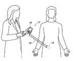
- FIG. 1is a view of a implantable assembly that acquires and processes electrical signals from central nervous system tissue, muscles and/or nerves inside the body using a general purpose MES processor.
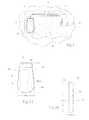
- FIG. 2Ais a front view of the general purpose MES processor shown in FIG. 1 .
- FIG. 2Bis a side view of the general purpose MES processor shown in FIG. 2A .
- FIG. 3is a view showing how the geometry of the MES processor shown in FIGS. 2A and 2B aids in its implantation in a tissue pocket.
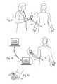
- FIG. 4Ais a view showing the MES processor shown in FIGS. 2A and 2B in association with a transcutaneous MES processor charger (battery recharger) including an integral charging coil which generates the RF magnetic field, and also showing the MES processor charger using wireless telemetry to communicate with the MES processor.
- a transcutaneous MES processor chargerbattery recharger
- FIG. 4Bis an anatomic view showing the transcutaneous MES processor charger (battery recharger) as shown in FIG. 4A , including a separate, cable coupled charging coil which generates the RF magnetic field, and also showing the MES processor charger using wireless telemetry to communicate with the MES processor.
- MES processor chargerbattery recharger
- FIG. 4Cis a perspective view of the MES processor charger of the type shown in FIGS. 4A and 4B , with the charger shown docked on a recharge base with the charging base connected to the power mains.
- FIG. 5Ais an anatomic view showing the MES processor shown in FIGS. 2A and 2B in association with an external programmer that relies upon wireless telemetry, and showing the programmer's capability of communicating with the MES processor up to an arm's length away from the MES processor.
- FIG. 5Bis a system view of an MES processor system incorporating a clinician programmer derivative and showing the system's capability of communicating and transferring data over a network, including a remote network.
- FIG. 5Cis a perspective view of a patient controller that may be used with the MES processor shown in FIGS. 2A and 2B .
- FIG. 6is a block diagram of a circuit that the MES processor shown in FIGS. 2A and 2B can incorporate.
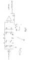
- FIG. 7is a circuit diagram showing a possible circuit for the wireless telemetry feature used with the MES processor shown in FIGS. 2A and 2B .
- FIG. 8is a circuit diagram showing a possible circuit for the amplification and filtering features used with the MES processor shown in FIGS. 2A and 2B .
- This circuitincludes provisions for the EMC/ESD suppression features used with the MES processor shown in FIGS. 2A and 2B .
- This circuitmay also include methods for the detection of stimulus artifacts and their subsequent suppression by processing software (firmware).
- FIG. 9is a graphical view of a typical myoelectric signal to be sensed by the MES processor while in use with the system shown in FIG. 1 .
- FIG. 10is a circuit diagram showing a possible circuit for the microcontroller used with the MES processor shown in FIGS. 2A and 2B .
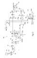
- FIG. 11is a circuit diagram showing one possible option for a power management sub-circuit where the sub-circuit includes MOSFET isolation between the battery and charger circuit, the power management sub-circuit being a part of the MES processor circuit shown in FIG. 6 .
- FIG. 12is a circuit diagram showing a second possible option for a power management sub-circuit where the sub-circuit does not include MOSFET isolation between the battery and charger circuit, the power management sub-circuit being a part of the MES processor circuit shown in FIG. 6 .
- FIG. 1shows an assembly 10 for acquisition and processing of myoelectric signals from central nervous system tissue, nerve, or a muscle, or a nerve and a muscle for therapeutic (treatment) or functional restoration purposes.
- the assemblyincludes at least one implantable lead 12 coupled to an MES processor 18 .
- the lead 12 and the MES processor 18are shown implanted within a tissue region T of a human or animal body.
- the distal end of the lead 12includes one or more electrically conductive surfaces, which will in shorthand be called a recording electrode or electrode 16 .
- the electrode 16is desirably a bipolar electrode, and is implanted in electrical conductive contact with at least one functional grouping of neural tissue, muscle, or at least one nerve, or at least one muscle and nerve.
- the MES processor 18includes a connection header 14 that desirably carries a plug-in receptacle for the lead 12 . In this way, the lead 12 electrically connects the electrode 16 to the MES processor 18 .
- the MES processor 18is sized and configured to be implanted subcutaneously in tissue, desirably in a subcutaneous pocket P, which can be remote from the electrode 16 , as FIG. 1 shows. Desirably, the MES processor 18 is sized and configured to be implanted using a minimally invasive surgical procedure.
- the surgical proceduremay be completed in a number of steps. For example, once a local anesthesia is established, the electrode 16 is positioned at the target site. Next, a subcutaneous pocket P is made and sized to accept the MES processor 18 . The pocket P is formed remote from the electrode 16 . Having developed the subcutaneous pocket P for the MES processor 18 , a subcutaneous tunnel is formed for connecting the lead 12 and electrode 16 to the MES processor 18 . The lead 12 is routed through the subcutaneous tunnel to the pocket site P where the MES processor 18 is to be implanted. The lead 12 is then coupled to the MES processor 18 , and both the lead 12 and MES processor 18 are placed into the subcutaneous pocket, which is sutured closed.
- the MES processor 18includes a circuit 20 that processes the electrical signals from the electrodes.
- An on-board, rechargeable battery 22desirably provides the power for the circuitry of the MES processor.
- the MES processor 18also desirably includes an on-board, programmable microcontroller 24 , which carries embedded code. The code expresses pre-programmed rules or algorithms under which the myoelectric signal is processed; including the control of the analog amplification and filtering element of circuit 20 .
- the MES processor 18processes the myoelectric signals sensed through the lead 12 and the electrode 16 .
- These sensed electrical signalsstem from neural activity of the central nervous system tissue, muscle, nerve, or both nerve and muscle tissue that lay in electrical conductive contact (i.e., within close proximity to the electrode surface where the electric field gradients from the nervous tissue are high) with the electrode 16 , in order to provide a desirable control function; often under voluntary control of the patient/user.
- control of a prosthetic limbis just one example of a prosthetic restoration result. Additional examples of desirable therapeutic (treatment) or functional restoration indications will be described in greater detail in section II.
- the assembly 10may also include additional operative components, such as but not limited to, a clinician programmer, a clinician programmer derivative, a patient controller, and an MES processor charger, each of which will be discussed later.
- additional operative componentssuch as but not limited to, a clinician programmer, a clinician programmer derivative, a patient controller, and an MES processor charger, each of which will be discussed later.
- the size and configuration of the MES processor 18makes possible its use as a general purpose or universal device (i.e., creating a platform technology), which can be used for many specific clinical indications requiring the acquisition and processing of electrical signals from central nervous system tissue, muscle and/or nervous tissue for therapeutic (treatment) or functional restoration purposes.
- Most of the components of the MES processor 18are desirably sized and configured so that they can accommodate several different indications, without major change or modification.
- Examples of components that desirably remain unchanged for different indicationsinclude the case 26 , the battery 22 , the power management circuitry 40 for recharging the battery 22 , the microcontroller 24 , the wireless telemetry circuitry, much of the software (firmware) of the embedded code, EMC/ESD suppression circuitry, and the amplification, and filtering circuitry.
- a new indicationmay require only changes to the programming of the microcontroller 24 .
- the particular codeis remotely embedded in the microcontroller 24 after final assembly, packaging, sterilization, and perhaps implantation of the MES processor 18 .
- connection header 14 and associated receptacle(s) for the leadmay be configured differently for different indications.
- Other aspects of the circuit 20may also be modified to accommodate a different indication; for example additional channels of MES processing.
- the MES processor 18is well suited for use for diverse indications.
- the MES processor 18thereby accommodates coupling to a lead 12 and an electrode 16 implanted in diverse tissue regions, which are targeted depending upon the therapeutic (treatment) or functional restoration results desired.
- the MES processor 18also accommodates coupling to a lead 12 and an electrode 16 having diverse forms and configurations, again depending upon the therapeutic or functional effects desired. For this reason, the MES processor can be considered to be general purpose or “universal.”
- the MES processor 18can incorporate various technical features to enhance its universality.
- the MES processor 18can be sized small enough to be implanted (or replaced) with only local anesthesia.
- the functional elements of the MES processor 18e.g., circuit 20 , the microcontroller 24 , the battery 22 , and the connection header 14
- the case 26defines a small cross section; e.g., (5 mm to 10 mm thick) ⁇ (30 mm to 40 mm wide) ⁇ (50 mm to 60 mm long), and an overall weight of approximately 20 to 25 grams.
- the case 26 of the MES processor 18is desirably shaped with a smaller end 30 and a larger end 32 . As FIG. 3 shows, this geometry allows the smaller end 30 of the case 26 to be placed into the skin pocket P first, with the larger end 32 being pushed in last.
- the case 26 for the MES processor 18comprises a laser welded titanium material.
- This constructionoffers high reliability with a low manufacturing cost.
- the clam shell constructionhas two stamped or successively drawn titanium case halves that are laser welded around the circuit assembly and battery 22 with feed-thrus.
- a molded plastic spacing nestis used to hold the battery 22 , the circuit 20 , and perhaps a power recovery (receive) coil 53 together and secure them within the titanium case.
- the MES processor 18 shown in FIGS. 2A and 2Bincludes a clam-shell case 26 having a thickness that is selected to provide adequate mechanical strength while balancing the greater power absorption and shielding effects to the low to medium frequency magnetic field used to transcutaneously recharge the MES processor Lithium Ion battery 22 with thicker case material (the competing factors are poor transformer action at low frequencies—due to the very low transfer impedances at low frequencies—and the high shielding losses at high frequencies).
- the selection of the thicknessensures that the titanium case allows adequate power coupling to recharge the secondary power source (described below) of the MES processor 18 at the target implant depth using a low frequency radio frequency (RF) magnetic field from an MES processor charger 34 mounted on the skin.
- RFradio frequency
- the MES processor 18is implanted at a target implant depth of not less than five millimeters beneath the skin, and not more than fifteen millimeters beneath the skin, although this implant depth may change due to the particular application, or the implant depth may change over time based on physical conditions of the patient, for example.
- the MES processor 18desirably possesses an internal battery capacity sufficient to allow operation with recharging not more frequently than once per week for many or most clinical applications.
- the battery 22 of the MES processor 18desirably can be recharged in less than approximately six hours with a recharging mechanism that allows the patient to sleep in bed or carry on most normal daily activities while recharging the battery 22 of the MES processor 18 .
- the battery 22 of the MES processor 18desirably comprises a secondary (rechargeable) power source; most desirably a Lithium Ion battery 22 .
- a secondary (rechargeable) power sourcemost desirably a Lithium Ion battery 22 .
- a 1.0 Amp-hr primary cell batterycan provide a service life of less than two years, which is too short to be clinically or commercially viable for this indication.
- the MES processor 18desirably incorporates a secondary battery 22 (a rechargeable battery), e.g., a Lithium Ion secondary battery that can be recharged transcutaneously.
- a Lithium Ion secondary batterywith a capacity of 30 mA-hr will operate for about two weeks.
- Lithium Ion implant grade batteriesare available from a domestic supplier.
- a representative batteryprovides 35 mA-hr in a package configuration that is of appropriate size and shape to fit within the MES processor 18 .
- the MES processor 18could also incorporate a small primary battery to provide current to prevent self-discharge of the secondary battery 22 from dropping its voltage to the point of irreversible damage to the secondary battery.
- the power for recharging the battery 22 of the MES processor 18is provided through the application of a low frequency (e.g., 30 KHz to 300 KHz) RF magnetic field applied by a skin or clothing mounted recharger 34 placed over the MES processor (see FIGS. 4A and 4B ).
- a low frequencye.g., 30 KHz to 300 KHz
- RF magnetic fieldapplied by a skin or clothing mounted recharger 34 placed over the MES processor (see FIGS. 4A and 4B ).
- a low frequencye.g., 30 KHz to 300 KHz
- the recharger 34might use a separate magnetic coupling coil (charging coil) 35 which is placed and/or secured on the skin or clothing over the MES processor 18 and connected by cable to the recharger 34 (circuitry and battery in a housing) that is worn on a belt or clipped to the clothing (see FIG. 4B ).
- a separate magnetic coupling coil (charging coil) 35which is placed and/or secured on the skin or clothing over the MES processor 18 and connected by cable to the recharger 34 (circuitry and battery in a housing) that is worn on a belt or clipped to the clothing (see FIG. 4B ).
- the charging coil 35preferably includes a predetermined construction, e.g., desirably 150 to 250 turns, and more desirably 200 turns of six strands of #36 enameled magnetic wire, or the like. Additionally, the charging coil mean diameter is in a range of about 40 millimeters to 60 millimeters, and desirably about 50 millimeters, although the diameter may vary. The thickness of the charging coil 35 as measured perpendicular to the mounting plane is to be significantly less than the diameter, e.g., two to five millimeters, so as to allow the coil to be embedded or laminated in a sheet to facilitate placement on or near the skin. Such a construction will allow for efficient power transfer and will allow the charging coil 35 to maintain a temperature below 41 degrees Celsius.
- the recharger 34preferably includes its own internal batteries which may be recharged from the power mains, for example.
- a charging base 39may be included to provide for convenient docking and recharging of the system's operative components, including the recharger and the recharger's internal batteries (see FIG. 4C ).
- the MES processor recharger 34does not need to be plugged into the power mains while in use to recharge the MES processor.
- the MES processor 18may be recharged while it is operating and will not increase in temperature by more than two degrees Celsius above the surrounding tissue during the recharging. It is desirable that the recharging of the battery 22 requires not more than six hours, and a recharging would be required between once per month to once per week depending upon the power requirements of the acquisition and processing activity.
- the MES processor 18desirably incorporates circuitry and/or programming to assure that the MES processor 18 will suspend MES acquisition and processing, and perhaps fall-back to only very low rate telemetry, and eventually suspends all operations when the secondary battery 22 has discharged the majority of it capacity (i.e., only a safety margin charge remains). Once in this dormant mode, the MES processor can be restored to normal operation only by recharging as shown in FIGS. 4A and 4B .
- the system or assembly 10includes an MES Processor 18 , which desirably incorporates wireless telemetry (rather that an inductively coupled telemetry) for a variety of functions to be performed within arm's reach of the patient, the functions including receipt of programming and clinical parameters and settings from the clinician programmer 36 , communicating usage history to the clinician programmer, providing user control of the MES processor 18 , and for controlling the RF magnetic field generated by the MES processor charger 34 .
- Each implantable MES processor 18may also have a unique signature that limits communication to only the dedicated controllers (e.g., the matched Patient Controller, MES processor charger, or a clinician programmer configured for the MES processor 18 in question).
- the MES processor 18desirably incorporates wireless telemetry as an element of the MES processor circuit 20 , a representative embodiment of which is shown in FIG. 6 .
- a circuit diagram 50 showing a desired configuration for the wireless telemetry featureis shown in FIG. 7 . It is to be appreciated that modifications to this circuit diagram configuration which produce the same or similar functions as described are within the scope of the invention.
- the assembly 10desirably includes a clinician programmer 36 that, through a wireless telemetry 38 , transfers commands, data, and programs into the MES processor 18 and retrieves data out of the MES processor 18 .
- the clinician programmermay communicate with more than one MES processor implanted in the same user.
- the MES processormay be used as part of a system with implantable stimulators that use a compatible wireless telemetry system.
- the communications between the MES Processor and the patient controllermay also be monitored by the implantable stimulator(s) and form an neuroprosthetic system with minimal communications originating from the patient controller.
- the clinician programmer 36may incorporate a custom programmed general purpose digital device, e.g., a custom program, industry standard handheld computing platform or other personal digital assistant (PDA).
- PDApersonal digital assistant
- the clinician programmer 36can include an on-board microcontroller powered by a rechargeable battery.
- the rechargeable battery of the clinician programmer 36may be recharged in the same or similar manner as described and shown for the recharger 34 , i.e., docked on a charging base 39 (see FIG. 4C ); or the custom electronics of the clinician programmer may receive power from the connected PDA.
- the microcontrollercarries embedded code which may include pre-programmed rules or algorithms that allow a clinician to remotely download acquisition and processing parameters into the MES processor 18 .
- the microcontroller of the clinician programmer 36is also desirably able to interrogate the MES processor and upload usage data from the MES processor.
- FIG. 5Ashows one possible application where the clinician is using the programmer 36 to interrogate the MES processor.
- FIG. 5Bshows an alternative application where the clinician programmer, or a clinician programmer derivative 33 intended for remote programming applications and having the same or similar functionality as the clinician programmer, is used to interrogate the MES processor.
- the clinician programmer derivative 33is connected to a local computer, allowing for remote interrogation via a local area network, wide area network, or Internet connection, for example.
- a clinician programmer derivativemay be included as a feature of the MES processor charger.
- features of the clinician programmer 36 or clinician programmer derivative 33might include the ability of the clinician or physician to remotely monitor and adjust parameters using the Internet or other known or future developed networking schemes.
- a clinician programmer derivative 33would desirably connect to the patient's computer in their home through an industry standard network such as the Universal Serial Bus (USB), where in turn an applet downloaded from the clinician's server would contain the necessary code to establish a reliable transport level connection between the MES processor 18 and the clinician's client software, using the clinician programmer derivative 33 as a bridge. Such a connection may also be established through separately installed software.
- the clinician or physiciancould then view relevant diagnostic information, such as the health of the unit or its current efficacy, and then direct the patient to take the appropriate action.
- Such a featurewould save the clinician, the patient and the health care system substantial time and money by reducing the number of office visits during the life of the implant.
- clinician programmerbased on an industry standard platform, might include the ability to connect to the clinician's computer system in his or hers office. Such features may take advantage of the Conduit connection employed by Palm OS® based devices. Such a connection then would transfer relevant patient data to the host computer or server for electronic processing and archiving. With a feature as described here, the clinician programmer then becomes an integral link in an electronic chain that provides better patient service by reducing the amount of paperwork that the physician's office needs to process on each office visit. It also improves the reliability of the service since it reduces the chance of mis-entered or mis-placed information, such as the record of the parameter setting adjusted during the visit.
- the wireless link 38allows a patient to control a limited range of parameters within the MES processor, such as operation modes/states, increase/decrease or optimize thresholds of MES activity associated with neuroprosthetic or therapeutic actions, or provide open or closed loop feedback from an external sensor or control source.
- the wireless telemetry 38also desirably allows the user to interrogate the MES processor 18 as to the status of its internal battery 22 .
- the full ranges within these parametersmay be controlled, adjusted, and limited by a clinician, so the user may not be allowed the full range of possible adjustments.
- the patient controller 37is sized and configured to couple to a key chain, as seen in FIG. 5C . It is to be appreciated that the patient controller 37 may take on any convenient shape, such as a ring on a finger, or a watch on a wrist, or an attachment to a belt, for example. It may also be desirable to combine both the functions of the MES processor charger and the patient controller into a single external device.
- the recharger 34 shown in FIGS. 4A and 4Bmay also use wireless telemetry to communicate with the MES processor 18 , so as to adjust the magnitude of the magnetic field to allow optimal recharging of the MES processor battery 22 while minimizing unnecessary power consumption by the recharger and power dissipation in the MES processor (through circuit losses and/or through absorption by MES processor case and construction).
- the wireless telemetrymay incorporate a suitable, low power wireless telemetry transceiver (radio) chip set that can operate in the MICS (Medical Implant Communications Service) band (402 MHz to 405 MHz) or other VHF/UHF low power, unlicensed bands.
- MICSMedical Implant Communications Service
- a wireless telemetry linknot only makes the task of communicating with the MES processor 18 easier, but it also makes the link suitable for use in motor control applications where the user voluntarily produces muscle contractions that are senses by the MES processor, and in turn, the MES processor issues a request to the external controller to activate an implantable pulse generator to produce stimulus pulses which in turn produce muscle contractions to achieve a functional goal (e.g., to squeeze a prosthetic hand or to stimulate ankle flexion to aid in the gait of an individual after a stroke) without requiring a coil or other component taped or placed on the skin over the implanted implantable pulse generator.
- a functional goale.g., to squeeze a prosthetic hand or to stimulate ankle flexion to aid in the gait of an individual after a stroke
- the MES processoris exclusively the communications slave, with all communications initiated by the external controller (the communications master).
- the receiver chip of the MES processoris OFF more than 99% of the time and is pulsed on periodically to search for a command from an external controller, including but not limited to the MES processor charger 34 , the clinician programmer 36 , and the patient controller 37 .
- Communications protocolsinclude appropriate check and message acknowledgment handshaking to assure the necessary accuracy and completeness of every message. Some operations (such as reprogramming or changing stimulus parameters) require rigorous message accuracy testing and acknowledgement. Other operations, such as a single user command value in a string of many consecutive values, might require less rigorous checking and a more loosely coupled acknowledgement.
- the timing with which the MES processor enables its transceiver to search for RF telemetry from an external controlleris precisely controlled (using a time base established by a quartz crystal) at a relatively low rate (e.g., twice per second; i.e., every 500 milliseconds).
- a relatively low ratee.g., twice per second; i.e., every 500 milliseconds.
- Thisallows the external controller to time when the MES processor responds to a command and then to synchronize its commands with when the MES processor will be listening for commands.
- Thisallows commands issued within a short time (seconds to minutes) of the last command to be captured and acted upon without having to ‘broadcast’ an idle or pause signal for 500 milliseconds before actually issuing the command in order to know that the MES processor will have enabled its receiver and received the command.
- the communications sequenceis configured to have the external controller issue commands in synchronization with when the MES processor will be listening for a command.
- the command set implementedis selected to minimize the number of messages necessary and the length of each message consistent with the appropriate level of error detection and message integrity monitoring. It is to be appreciated that the monitoring rate may vary faster or slower depending on the application; and may vary over time within a given application.
- the input processing firmwareallows the telemetry link to be idle except when myoelectric signal activity corresponds to a command or other important sequence. At that point the wireless telemetry can become active with a higher average data rate. In normal operation, the average latency between a MES event and the associated data on the telemetry link is about 1/10 second.
- the MES processormight fully implement a control algorithm and telemeter out the final result/command (for a prosthesis, neuroprosthesis, or therapeutic application); or it might partially process the MES signal(s) and telemeter out the intermediate result; or it might perform data compression and telemeter out the compressed MES data for processing by other devices.
- an external wireless accessoryreceives the wireless telemetry from the implanted MES processor and can provide a control signal to other appliances or recode and transmit new commands to a implantable pulse generator used as an FES neuroprostheses.
- the implanted or external devicescould directly monitor the data being telemetered from the MES processor.
- the wireless interface device(which must be located within about two meters of the implanted device) could provide the received data to a general purpose computer (perhaps a Personal Digital Assistant (PDA)) through a USB serial port.
- PDAPersonal Digital Assistant
- a suitable radio chipis used for the half duplex wireless communications, e.g., the AMIS-52100 (AMI Semiconductor; Pocatello, Id.).
- AMIS-52100AMI Semiconductor; Pocatello, Id.
- This transceiver chipis designed specifically for the MICS and its European counter-part the ULP-AMI (Ultra Low Power-Active Medical Implant) band.
- This chip setis optimized by micro-power operation with rapid start-up, and RF ‘sniffing’ circuitry.
- the MES processor circuit 20desirably incorporates one or more independent myoelectric signal recording channels 100 (see FIG. 6 ) coupled to a recording electrode 16 .
- FIG. 9is a graphical view of a typical myoelectric signal to be sensed by the MES processor while in use with the system shown in FIG. 1 .
- Each channel 100has an instrumentation amplifier 102 designed for minimizing the magnitude of signal artifacts.
- These artifactscould arise from conventional sources of MES interference (presence of externally generated 60 Hz electric or magnetic fields, presence of higher frequency (RF) electromagnetic fields associated with the external environment, changing forces or pressures on the tissue over the recording electrodes, etc.).
- the MES artifactscould also arise from the use of electrical stimulation near the MES processor or its electrodes and leads. Specifically, if the MES processor is being used as part of a neuroprosthetic system or as part of a therapeutic system that incorporates electrical stimulation of muscles in the same extremity (or body region) as the MES processor; such stimulus artifact is likely to contaminate the MES signal.
- the central methods for minimizing these artifactsdesirably include one or more of the following features: (1) the instrumentation amplifier should maintain a high common mode rejection ratio throughout the frequency range of the artifact (note that the instrumentation amplifier should reject common mode signals at frequencies lower than the EMG signal); (2) the inputs to the instrumentation amplifier should be protected from damage by Electrostatic Discharge (ESD); (3) the inputs to the instrumentation amplifier should be filtered to reduce the harmful effects of radio frequency interference (RFI); (4) the coupling of the electrodes to the instrumentation amplifier should not excessively degrade the effective common mode rejection ratio (CMRR) of the instrumentation amplifier (which may be problematic at low frequencies); (5) the ESD protection and RFI filtering methods should not excessively degrade the effective CMRR of the instrumentation amplifier (especially problematic at low frequencies), and (6) the common mode voltage of the MES signal (available as an intermediate output of the instrumentation amplifier) is monitored by hardware and used to suspend MES processing during and immediately after very high artifact levels (typically stimulus artifact).
- ESDElectro
- each instrumentation amplifier(one per MES channel) is then bandpass filtered by a bandpass filter 104 .
- the low band edgeeliminates the DC content and frequencies where the artifact can be large and there is little EMG content.
- the high band edgecorresponds to an anti-aliasing filtering before the signal is digitized.
- These bandpass filtered signalsare then sampled (digitized) by the 12-bit analog to digital converter channels of the microcontroller 24 .
- FIG. 8A representative signal processing circuitry of a given myoelectric signal recording channel 100 is shown in FIG. 8 .
- D 8 and D 9are the transient suppressor diodes which clamp the voltage from the MES electrodes to ground (the case of the MES processor) in the event of large ESD or EMC disruptions; but these components have no current flow in normal operation (including during typical MES artifacts).
- L 6 -C 39 and L 7 -C 40form RFI filters to attenuate RFI to circuit common. These parts might incorporate ferrite elements and may be designed for maximal efficiency in attenuating common-mode voltages.
- R 27 -C 43 and R 28 -C 44form R-C filters that further attenuate RFI and higher audio frequency signal artifacts.
- a common mode return nodejunction of R 29 , C 43 , R 30 , C 44 , R 31 , C 45 , and R 32 ) that has the DC voltage established by VREF, very high frequency signals attenuated, and for MES passband signals, is at the AC potential of the common mode signal of the MES inputs.
- VREFis a voltage that assures the inputs of the instrumentation amplifier remain in the acceptable range of common mode input voltage.
- VREFis typically half of the power supply voltage powering the instrumentation amplifier.
- R 31is typically very large (much greater than the electrode source impedance) and is used to provide bias current to the inputs of the instrumentation amplifier.
- C 45assures that the common mode return node does not have any RF or very high audio frequency noise.
- C 46 and R 32drive the common mode return node with a voltage which is the average (common mode) of the inverting ( ⁇ ) and non-inverting (+) input of the instrumentation amplifier. This ‘bootstrapped’ design minimizes the impact of the filtering components on the overall common mode rejection of the amplifier.
- the response of the instrumentation amplifier to the anticipated MES signal artifactsshould be well behaved; i.e., the MES_Signal output may be contaminated by the artifact, but it should not invoke a slow overload recovery process or otherwise inject current into the input filtering networks.
- the digital signal processingperformed by the microcontroller 24 , will include the gating (suspension) of MES signal computations during and immediately following the detection of high common mode signals (likely stimulus artifact).
- the digital signal processingis described in more detail later.
- the results of the digital signal processingare sent via wireless telemetry link 50 (as shown in FIG. 6 for which a representative circuit is shown in FIG. 7 ) to the external device(s) and may also be monitored by other implanted devices.
- the MES processor 18desirably includes a lead connection header 14 for connecting the lead(s) 12 that will enable reliable and easy replacement of the lead/electrode (see FIGS. 2A and 2B ), and includes a small antenna 54 for use with the wireless telemetry feature.
- the MES processordesirably incorporates a connection header (top header) 14 (see FIGS. 2 A and 2 B 0 that is easy to use, reliable, and robust enough to allow multiple replacements of the MES processor after many years (e.g., more than ten years) of use.
- the surgical complexity of replacing an MES processoris usually low compared to the surgical complexity of correctly placing the implantable lead 12 /electrode 16 in proximity to the target nerve/tissue and routing the lead 12 to the MES processor.
- the lead 12 and electrode 16desirably has a service life of at least ten years with a probable service life of fifteen years or more. Based on the clinical application, the MES processor may not have this long a service life.
- the MES processor service lifeis largely determined by the number of charge-discharge cycles of the Lithium Ion battery 22 , and is likely to be three to ten years, based on the usage of the device. Most desirably, the MES processor 18 has a service life of at least five years.
- the MES processorpreferably will use a laser welded titanium case.
- the implantable lead(s) 12connect to the MES processor through a molded or cast polymeric connection header 14 (top header).
- Metal-ceramic or metal-glass feed-thrusmaintain the hermetic seal of the titanium capsule while providing electrical contact to the two or more electrical contacts of the lead 12 /electrode 16 .
- the standard implantable connectorsmay be similar in design and construction to the low-profile IS-1 connector system (per ISO 5841-3) or the IS-4 connector system which is still in draft form.
- the IS-1 connectorshave been in use since the late 1980s and have been shown to be reliable and provide easy release and re-connection over several MES processor replacements during the service life of a single recording lead.
- Full compatibility with the IS-1 standard or the IS-4 draft, and mating with recording leads,is not a requirement for the MES processor.
- the MES processor connection systemmay include a modification of the IS-4 connector system, which shrinks the axial length dimensions while keeping the format and radial dimensions of the IS-4.
- the top header 14may incorporate one or more connection receptacles each of which accommodate leads with typically four conductors.
- the design of the MES processor housing and header 14preferably includes provisions for adding the additional feed-thrus and larger headers for such indications.
- connection header (top header) 14The inclusion of the UHF antenna 54 for the wireless telemetry inside the connection header (top header) 14 is necessary as the shielding offered by the titanium case will severely limit (effectively eliminate) radio wave propagation through the case.
- the antenna 54 connectionwill be made through a feed-thru similar to that used for the electrode connections.
- the wireless telemetry signalmay be coupled inside the MES processor onto a electrical signal input channel and coupled to the antenna 54 with passive filtering/coupling elements/methods in the connection header 14 .
- the MES processor 18desirably uses a standard, commercially available micro-power, flash programmable microcontroller 24 or processor core in an application specific integrated circuit (ASIC).
- ASICapplication specific integrated circuit
- This deviceor possibly more than one such device for a computationally complex application
- other large semiconductor componentsmay have custom packaging such as chip-on-board, solder flip chip, or adhesive flip chip to reduce circuit board real estate needs.
- FIG. 10A circuit diagram showing a representative configuration for the microcontroller 24 is shown in FIG. 10 . It is to be appreciated that modifications to this circuit diagram configuration which produce the same or similar functions as described are within the scope of the invention.
- the MES processor 18desirably includes efficient power management circuitry 106 as an element of the MES processor circuitry 20 shown in FIG. 6 .
- the power management circuitry 106is generally responsible for the efficient distribution of power, the recovery of power from the RF magnetic field, and for charging and monitoring the Lithium Ion battery 22 .
- the operation of the MES processor 18can be described in terms of having operating modes as relating to the function of the power management circuitry. These modes may include, but are not limited to Active and Charging, Active, and Dormant. These modes will be described below in terms of the principles of operation of the power management circuitry using possible circuit diagrams shown in FIGS. 11 and 12 .
- FIG. 11shows one possible power management sub-circuit 106 having MOSFET isolation between the battery 22 and the charger circuit.
- FIG. 12shows another possible power management sub-circuit 106 without having MOSFET isolation between the battery 22 and the charger circuit.
- the leakage current of the disabled charge control integrated circuit chip (U 1 )must be very low to prevent this leakage current from discharging the battery 22 in all modes (including the Dormant Mode). Except as noted, the description of these modes applies to both circuits.
- the Active and Charging modeoccurs when the MES processor 18 is being charged.
- the MES processoris active, i.e., the microcontroller 24 is powered and coordinating wireless communications and may be timing and controlling the acquisition and processing of myoelectric signals.
- the MES processor 18may be communicating with the MES processor charger 34 concerning the magnitude of the battery voltage and the DC voltage recovered from the RF magnetic field.
- the charger 34uses this data for two purposes: to provide feedback to the user about the proximity of the charging coil 35 (see FIGS. 4A and 4B ) to the implanted MES processor 18 , and to increase or decrease the strength of the RF magnetic field. This, in turn, minimizes the power losses and undesirable heating of the MES processor.
- the power management circuitry 40serves one or more of the following primary functions: (1) provides battery power to the rest of the MES processor circuitry; (2) recovers power from the RF magnetic field generated by the MES processor charger 34 ; (3) provides controlled charging current (from the recovered power) to the battery 22 ; and (4) communicates with the MES processor charger 34 via the wireless telemetry link 38 to provide feedback to the user positioning the charging coil 35 over the MES processor, and to cause the MES processor charger 34 to increase or decrease the strength of its RF magnetic field for optimal charging of the MES processor battery 22 (e.g., a Lithium Ion battery).
- the MES processor battery 22e.g., a Lithium Ion battery
- the Active modeoccurs when the MES processor 18 is not being charged and it is operating normally. In this mode, the MES processor may be acquiring and processing sensed signals or it may be waiting for the next request to sample myoelectric signals in response to a timed sampling sequence or a telemetry command from an external controller. In this mode, the MES processor is active (microcontroller 24 is powered and coordinating wireless communications and may be timing & controlling the acquisition and processing of myoelectric signals). There is no MES processor charger 34 present.
- the lack of DC current from VRAWmeans that Q 5 is held off. This, in turn, holds Q 3 off and the charging circuitry is isolated from the battery 22 .
- the lack of DC current from VRAWmeans that U 1 is disabled. This, in turn, keeps the current drain from the battery 22 to an acceptably low level, typically less than 1 ⁇ A.
- the Dormant modeoccurs when the MES processor 18 is not being charged and it is completely disabled (powered down). In this mode, power is not being supplied to the microcontroller 24 or other enabled circuitry. This is the mode for the long-term storage of the MES processor before or after implantation.
- the Dormant modemay only be exited by placing the MES processor into the Active and Charging mode by placing the MES processor charging coil 35 of a functional MES processor charger 34 in close proximity to the MES processor 18 .
- the Dormant modethere is no MES processor charger 34 present, and thus no DC voltage recovered by Receive Coil 53 , D 1 , D 2 , and C 3 .
- VBATis not delivered to the remainder of the MES processor circuitry because Q 4 is turned off.
- the Dormant modeis stable because the lack of VBAT means that VCC is also not present, and thus Q 6 is not held on through R 8 and R 10 .
- the battery 22is completely isolated from all load circuitry (the VCC power supply and the VHH power supply).
- the Dormant modeis entered through the application of a long magnet placement over S 1 (magnetic reed switch) or through the reception of a command by the wireless telemetry.
- the PortD4which is normally configured as a microcontroller input, is configured as a logic output with a logic low (0) value. This, in turn, discharges C 8 through R 12 and turns off Q 6 ; which, in turn, turns off Q 4 and forces the MES processor into the Dormant mode.
- R 12is much smaller in value than R 10 , thus the microcontroller 24 can force C 8 to discharge even though VCC is still present.
- the lack of DC current from VRAWmeans that Q 5 is held off. This, in turn, holds Q 3 off and the charging circuitry is isolated from the battery 22 . Also, Q 4 was turned off.
- the lack of DC current from VRAWmeans that U 1 is disabled. This, in turn, keeps the current drain from the battery 22 to an acceptably low level, typically less than 1 ⁇ A.
- FIG. 6shows a representative circuit 20 for the MES processor 18 that takes into account the desirable technical features discussed above.
- the circuit 20can be grouped into functional blocks, which generally correspond to the association and interconnection of the electronic components.
- FIG. 6shows a block diagram that provides an overview of a representative desirable MES processor design.
- FIG. 6seven functional blocks are shown: (1) The Microprocessor or Microcontroller 24 ; (2) the Power Management Circuit 40 for the battery 22 ; (3) the VCC Power Supply 42 ; (4) the Input Coupling, EMC/ESD Networks 44 ; (5) the Instrumentation Amplifiers, 46 ; (6) the Bandpass filters 104 ; and (7) the Wireless Telemetry Circuit 50 .
- the Microcontroller 24is generally responsible for the following functions:
- a microcontroller incorporating flash programmable memoryallows the operating program (processing and/or compression algorithms) of the MES processor as well as the processing parameters, settings, and thresholds and usage history to be stored in non-volatile memory (data remains safely stored even if the battery 22 becomes fully discharged). Yet, the non-volatile memory can be erased and reprogrammed thousands of times during the life of the MES processor.
- the software (firmware) of the MES processormust be segmented to support the operation of the wireless telemetry routines while the flash memory of the microcontroller 24 is being erased and reprogrammed.
- the VCC power supply 42must support the power requirements of the microcontroller 24 during the flash memory erase and program operations.
- the digital signal processing algorithms that will be employedmay include comparison of processed values with pre-defined thresholds.
- the processing valuemay include average of rectified value, root-mean-square (rms) value, mean-squared value, number of zero crossings, ratio of energy in one band of frequencies to the energy in another band, rate of change (first order time derivative) of rectified value or rms, Finite Impulse Response (FIR) filtering, Infinite Impulse Response 9IIR) filtering, or one of several adaptive filtering algorithms.
- FIRFinite Impulse Response
- IIRInfinite Impulse Response
- the Components of the Microcontroller Circuitmay include:
- a single chip microcontroller 24may be a member of the Texas Instruments MSP430 family of flash programmable, micro-power, highly integrated mixed signal microcontroller. Likely family members to be used include the MSP430F1610, MSP430F1611, MSP430F1612, MSP430F168, and the MSP430F169. Each of these parts has numerous internal peripherals, and a micropower internal organization that allows unused peripherals to be configured by minimal power dissipation, and an instruction set that supports bursts of operation separated by intervals of sleep where the microcontroller suspends most functions.
- a miniature, quartz crystal (X 1 ) for establishing precise timing of the microcontrollerThis may be a 32.768 KHz quartz crystal.
- the Power Management Circuit 40is generally responsible for the following functions:
- (11)provide a hard microprocessor reset and force entry into the Dormant Mode in the presence of a pacemaker magnet (or comparable device), and
- (12)provide the microcontroller 24 with analog voltages with which to measure the magnitude of the recovered power from the RF magnetic field 52 , the battery voltage, and the appropriate battery current flow (drain and charge).
- the Components of the Power Management Circuitmay include:
- the Receive Coil 53which desirably comprises a multi-turn, fine copper wire coil near the inside perimeter of the MES processor 18 .
- the receive coil 53includes a predetermined construction, e.g., desirably 250 to 350 turns, and more desirably 300 turns of four strands of #40 enameled magnetic wire, or the like. The maximizing of the coil's diameter and reduction of its effective RF resistance allows necessary power transfer at typical implant depth of about one centimeter.
- a micropower Lithium Ion battery charge management controller ICintegrated circuit
- MicroChip MCP73843-41integrated circuit
- the VCC Power Supply 42is generally responsible for the following functions:
- the Components of the VCC Power Supplymight include:
- Micropower, low drop out, linear voltage regulatore.g., Microchip NCP1700T-3302, Maxim Semiconductor MAX1725, or Texas Instruments TPS79730, or the like.
- quiescent currenti.e., the current wasted by the power supply in its normal operation. This value should be less than a few microamperes, and
- drop-out voltagei.e., the minimal difference between the VBAT supplied to the VCC power supply and its output voltage. This voltage may be less than about 100 mV even at the current loads presented by the transmitter of the wireless telemetry circuitry.
- Each MES channelhas (typically) two differential inputs from a bipolar electrode located near a muscle or other excitable nervous system tissue. These two signal, in turn, may also have voltage transients caused by Electrostatic Discharges (ESD) to the body near the implanted MES processor or electrodes. These transient voltages can damage the instrumentation amplifiers and must be limited by passive components near the electrode connections. This function is typically provided by small signal silicon diodes back biased to the supply rails of the instrumentation amplifier or by silicone transient voltage suppressor diodes (similar to back-to-back zener diodes).
- ESDElectrostatic Discharges
- radiofrequency interferenceradiofrequency interference
- RFIDradiofrequency interference
- large RFI signalscan introduce non-linearities in the instrumentation amplifiers and cause an artifact that is within the passband of the MES signals.
- This RFImust be attenuated to an acceptable level before it is applied to the input of the instrumentation amplifier. This is typically accomplished by using passive filtering components; including small ferrite L-R-C networks as well as lumped components.
- the electrodesthemselves may or may not be capable of supporting the bias current of the instrumentation amplifier without developing an offset (polarization) voltage. This is a function of the electrode material used and the bias currents involved.
- An input coupling capacitors to block the DC current from the instrumentation amplifier from flowing through the electrodesmay be used resolve this problem.
- the instrumentation amplifiers 46serve two functions: to amplify the differential voltage between the two bipolar electrode connections of a given channel, and the reject (given no gain) to the voltage that is common to both signals.
- the instrumentation amplifiersmust accept signals with up to 200 mVpp of common mode noise.
- the instrumentation amplifiersmust have a high differential impedance (the electrode circuit source impedances may typically be between 500 ohms and 2,000 ohms).
- the instrumentation amplifiersmust have a very high common mode input impedance.
- the instrumentation amplifiersmay have a provision for the microcontroller to program their gain.
- a typical input signalwill have an amplitude of 1 mVpp to 20 mVpp.
- the output signalwill typically be about 1 Vpp.
- the instrumentation amplifiersmust also have adequate gain-bandwidth product to provide the necessary gain and CMRR throughout the MES passband (approx. 10 Hz-500 Hz or 1 KHz).
- the bandpass filters 104serve two functions: to eliminate (filter out) low frequency signals that have little MES content and may have a lot of artifact content; and to filter out signals (both MES and artifact) that are changing so fast as to confuse the sampling process (so called anti-alias filtering). It is anticipated that the digital signal processing algorithms will sample the MES signals at 1,000 or 2,000 samples per second. It is anticipated that relatively simple analog filters would be adequate for these purposes. More sophisticated, higher order filters may be used for the lowpass (high frequency attenuation, anti-aliasing) function.
- the Wireless Telemetry circuit 50is generally responsible for the following functions:
- VHF-UHF RF linklikely in the 4.02 MHZ to 405 MHz MICS band per FCC 47 CFR Part 95 and the Ultra Low Power-Active Medical Implant (AMI) regulations of the European Union.
- This circuitwill look for RF commands at precisely timed intervals (e.g., twice a second), and this function must consume very little power. Much less frequently this circuit will transmit to the external controller. This function should also be as low power as possible; but will represent a lower total energy demand than the receiver in most of the anticipated applications.
- the RF carrieris amplitude modulated (on-off keyed) with the digital data.
- Serial datais generated by the microcontroller 24 already formatted and timed.
- the wireless telemetry circuit 50converts the serial data stream into a pulsing carrier signal during the transit process; and it converts a varying RF signal strength into a serial data stream during the receive process.
- the Components of the Wireless Telemetry Circuit 50might include:
- a crystal controlled, micropower transceiver chipsuch as the AMI Semiconductor AMIS-52100 (U 6 ). This chip is responsible for generating the RF carrier during transmissions and for amplifying, receiving, and detecting (converting to a logic level) the received RF signals.
- the transceiver chipmust also be capable of quickly starting and stopping operation to minimize power consumption by keeping the chip disabled (and consuming very little power) the majority of the time; and powering up for only as long as required for the transmitting or receiving purpose.
- the transceiver chiphas separate transmit and receive ports that must be switched to a single antenna/feedthru. This function is performed by the transmit/receive switch (U 5 ) under microcontroller control via the logic line XMIT.
- the microcontroller 24controls the operation of the transceiver chip via an I 2 C serial communications link.
- the serial data to and from the transceiver chipmay be handled by a UART or a SPI peripheral of the microcontroller.
- the message encoding/decoding and error detectionmay be performed by a separate, dedicated microcontroller; else this processing will be time shared with the other tasks of the only microcontroller.
- the various inductor and capacitor components (U 6 ) surrounding the transceiver chip and the transmit/receive switch (U 5 )are impedance matching components and harmonic filtering components, except as follows:
- X 2 , C 33 and C 34are used to generate the crystal controlled carrier, desirably tuned to the carrier frequency divided by thirty-two,
- L 4 and C 27form the tuned elements of a VCO (voltage controlled oscillator) operating at twice the carrier frequency
- R 20 , C 29 , and C 30are filter components of the PLL (phase locked loop) filter.
- the MES processor 18can be used to acquire and process myoelectric signals into instruction signals. These instruction signals can then be sent using wireless telemetry to a control device, such as a controller for an artificial limb, or to an implantable pulse generator, in order to provide beneficial results in diverse therapeutic and functional restorations indications.
- a control devicesuch as a controller for an artificial limb, or to an implantable pulse generator
- possible indications for use of the MES processor 18include the detection of excessive or inadequate nervous system activity to invoke or control the application of energy or drugs for the treatment of (i) urinary and fecal incontinence; (ii) micturition/retention; (iii) restoration of sexual function; (iv) defecation/constipation; (v) pelvic floor muscle activity; and/or (vi) pelvic pain.
- the MES processor 18can be used for the detection of excessive or inadequate nervous system activity to invoke or control the application of energy or drugs (e.g., deep brain stimulation) for the treatment of in the treatment of (i) Parkinson's disease; (ii) multiple sclerosis; (iii) essential tremor; (iv) depression; (v) eating disorders; (vi) epilepsy; and/or (vii) minimally conscious state.
- energy or drugse.g., deep brain stimulation
- the MES processor 18can be used for the detection of excessive or inadequate nervous system activity to invoke or control the application of energy or drugs in the treatment of pain, e.g., (i) peripheral neuropathy; and/or (ii) cancer.
- the MES processor 18can be used for the detection of excessive or inadequate nervous system activity to invoke or control the application of energy or drugs (e.g., vagal nerve stimulation) for control of epilepsy, depression, or other mood/psychiatric disorders.
- energy or drugse.g., vagal nerve stimulation
- the MES processor 18can be used for the detection of excessive or inadequate nervous system activity to invoke or control the application of energy or drugs for the treatment of obstructive sleep apnea.
- the MES processor 18can be used for the detection of excessive or inadequate nervous system activity to invoke or control the application of energy or drugs to prevent reflux or to reduce appetite or food consumption.
- the MES processor 18can be used for the detection of excessive or inadequate nervous system activity to invoke or control the application of energy or drugs in functional restorations indications such as the restoration of motor control, to restore (i) impaired gait after stroke or spinal cord injury (SCI); (ii) impaired hand and arm function after stroke or SCI; (iii) respiratory disorders; (iv) swallowing disorders; (v) sleep apnea; and/or (vi) neurotherapeutics, allowing individuals with neurological deficits, such as stroke survivors or those with multiple sclerosis, to recover functionally.
- functional restorations indicationssuch as the restoration of motor control
Landscapes
- Health & Medical Sciences (AREA)
- Life Sciences & Earth Sciences (AREA)
- Engineering & Computer Science (AREA)
- Veterinary Medicine (AREA)
- Biomedical Technology (AREA)
- Animal Behavior & Ethology (AREA)
- General Health & Medical Sciences (AREA)
- Public Health (AREA)
- Neurology (AREA)
- Medical Informatics (AREA)
- Physics & Mathematics (AREA)
- Biophysics (AREA)
- Pathology (AREA)
- Heart & Thoracic Surgery (AREA)
- Radiology & Medical Imaging (AREA)
- Molecular Biology (AREA)
- Surgery (AREA)
- Nuclear Medicine, Radiotherapy & Molecular Imaging (AREA)
- Neurosurgery (AREA)
- Computer Networks & Wireless Communication (AREA)
- Physiology (AREA)
- Electrotherapy Devices (AREA)
Abstract
Description
- i(a)(1) As
FIGS. 11 and 12 show, RF voltage is induced in the ReceiveCoil 53 by the RFmagnetic field 52 of theMES processor charger 34 - i(a)(2) Capacitor C1 is in series with the Receive
Coil 53 and is selected to introduce a capacitive reactance that compensates (subtracts) the inductive reactance of the Receive Coil - i(a)(3) D1-D2 form a full wave rectifier that converts the AC voltage recovered by the Receive.
Coil 53 into a pulsating DC current flow - i(a)(4) This pulsating DC current is smoothed (filtered) by C3 (this filtered DC voltage is labeled VRAW)
- i(a)(5) D4 is a zener diode that acts as a voltage limiting device (in normal operation, D4 is not conducting significant current)
- i(a)(6) D3 prevents the flow of current from the
battery 22 from preventing the correct operation of the Charge Management Circuitry once the voltage recovered from the RF magnetic field is removed. Specifically, current flow from the battery [through Q3 (turned ON), in the case for the circuit ofFIG. 11 ] through the body diode of Q2 would hold ON the charge controller IC (U1). This additional current drain would be present in all modes, including dormant, and would seriously limit battery operating life. Additionally, this battery current pathway would keep Q6 turned ON even if the magnetic reed switch (S1) were closed; thus preventing the isolation of the IPG circuitry from the battery in the dormant mode. - i(a)(7) In
FIG. 11 , D3 is desirably a schottky diode because of the lower forward voltage drop; whereas it is desirably a conventional silicone diode inFIG. 12 because of the lower reverse voltage leakage current. - i(a)(8) U1, Q2, R2, C4, C6, and C2 form the battery charger sub-circuit
- U1 is a micropower, Lithium Ion Charge Management Controller chip implementing a constant current phase and constant voltage phase charge regime. This chip desirably incorporates an internal voltage reference of high accuracy (+/−0.5%) to establish the constant voltage charge level. U1 performs the following functions:
- monitors the voltage drop across a series resistor R2 (effectively the current charging the battery22) to control the current delivered to the battery through the external pass transistor Q2. U1 uses this voltage across R2 to establish the current of the constant current phase (typically the battery capacity divided by five hours), and
- decreases the current charging the battery as required to limit the battery voltage and effectively transition from constant current phase to constant voltage phase as the battery voltage approaches the terminal voltage,
- i(a)(9) U1 also includes provisions for timing the duration of the constant current and constant voltage phases and suspends the application of current to the
battery 22 if too much time is spent in the phase. These fault timing features of U1 are not used in normal operation. - i(a)(10) In this circuit, the constant voltage phase of the battery charging sequence is timed by the
microcontroller 24 and not by U1. The microcontroller monitors the battery voltage and terminates the charging sequence (i.e., tells theMES processor charger 34 that theMES processor battery 22 is fully charged) after the battery voltage has been in the constant voltage region for greater than a fixed time period (e.g., 15 to 20 minutes). - i(a)(11) In
FIG. 11 , Q3 and Q5 are turned ON only when the charging power is present. This effectively isolates the charging circuit from thebattery 22 when the externally supplied RFmagnetic field 52 is not present and providing power to charge the battery. - i(a)(12) In
FIG. 12 , U1 is always connected to thebattery 22, and the disabled current of this chip is a load on thebattery 22 in all modes (including the dormant mode). This, in turn, is a more demanding requirement on the current consumed by U1 while disabled. - i(a)(13) F1 is a fuse that protects against long-duration, high current component failures. In all anticipated transient high current failures, (i.e., soft failures that cause the circuitry to consume high current levels and thus dissipate high power levels; but the failure initiating the high current flow is not permanent and the circuit will resume normal function if the circuit is removed from the power source before damage from overheating occurs), the VBAT circuitry will disconnect the
battery 22 from the temporary high load without blowing the fuse. The specific sequence is:- (1) High current flows into a component(s) powered by VBAT (most likely the VHH power supply or an element powered by the VCC power supply).
- (2) The voltage drop across the fuse will (prior to the fuse blowing) turn ON Q1 (based on the current flow through the fuse causing a 0.5V to 0.6V drop across the resistance of F1).
- (3) The collector current from Q1 will turn off Q4.
- (4) VBAT drops very quickly and, as a direct result, VCC falls. In turn, the voltage on the PortD4 IO pin from the microcontroller voltage falls as VCC falls, through the parasitic diodes in the
microcontroller 24. This then pulls down the voltage across C6 as it is discharged through R12. - (5) The MES processor is now stable in the Dormant Mode, i.e., VBAT is disconnected from the
battery 22 by a turned OFF Q4. The only load remaining on the battery is presented by the charging circuit and by the analog multiplexer (switches) U3 that are used to direct an analog voltage to themicrocontroller 24 for monitoring the battery voltage and (by subtracting the voltage after the resistance of F1) an estimate of the current consumption of the entire circuit. A failure of these voltage monitoring circuits is not protected by the fuse, but resistance values limit the current flow to safe levels even in the event of component failures. A possible source of a transient high-current circuit failure is the SCR latchup or supply-to-ground short failure of a semiconductor device directly connected to VBAT or VCC.
- R9 & R11 form a voltage divider to convert VRAW (approximately zero volts to eight volts) into the voltage range of the microcontroller's A-D inputs (used for closed loop control of the RF magnetic field strength),
- i(a)(14) R8 and C9 form the usual R-C reset input circuit for the
microcontroller 24; this circuit causes a hardware reset when the magnetic reed switch (S1) is closed by the application of a suitable static magnetic field for a short duration, - (a)(15) R10 and C8 form a much slower time constant that allows the closure of the reed switch by the application of the static magnetic field for a long duration to force the MES processor into the Dormant mode by turning OFF Q6 and thus turning OFF Q4. The use of the magnetic reed switch for resetting the
microcontroller 24 or forcing a total MES processor shutdown (Dormant mode) may be a desirable safety feature.
- i(a)(1) As
Claims (8)
Priority Applications (1)
| Application Number | Priority Date | Filing Date | Title |
|---|---|---|---|
| US11/974,279US8195304B2 (en) | 2004-06-10 | 2007-10-12 | Implantable systems and methods for acquisition and processing of electrical signals |
Applications Claiming Priority (5)
| Application Number | Priority Date | Filing Date | Title |
|---|---|---|---|
| US57874204P | 2004-06-10 | 2004-06-10 | |
| US59919304P | 2004-08-05 | 2004-08-05 | |
| US68059805P | 2005-05-13 | 2005-05-13 | |
| US11/150,734US7283867B2 (en) | 2004-06-10 | 2005-06-10 | Implantable system and methods for acquisition and processing of electrical signals from muscles and/or nerves and/or central nervous system tissue |
| US11/974,279US8195304B2 (en) | 2004-06-10 | 2007-10-12 | Implantable systems and methods for acquisition and processing of electrical signals |
Related Parent Applications (2)
| Application Number | Title | Priority Date | Filing Date |
|---|---|---|---|
| US11/150,734ContinuationUS7283867B2 (en) | 2004-06-10 | 2005-06-10 | Implantable system and methods for acquisition and processing of electrical signals from muscles and/or nerves and/or central nervous system tissue |
| US11/150,734DivisionUS7283867B2 (en) | 2004-06-10 | 2005-06-10 | Implantable system and methods for acquisition and processing of electrical signals from muscles and/or nerves and/or central nervous system tissue |
Publications (2)
| Publication Number | Publication Date |
|---|---|
| US20080132974A1 US20080132974A1 (en) | 2008-06-05 |
| US8195304B2true US8195304B2 (en) | 2012-06-05 |
Family
ID=39476778
Family Applications (1)
| Application Number | Title | Priority Date | Filing Date |
|---|---|---|---|
| US11/974,279Expired - Fee RelatedUS8195304B2 (en) | 2004-06-10 | 2007-10-12 | Implantable systems and methods for acquisition and processing of electrical signals |
Country Status (1)
| Country | Link |
|---|---|
| US (1) | US8195304B2 (en) |
Cited By (38)
| Publication number | Priority date | Publication date | Assignee | Title |
|---|---|---|---|---|
| US20070270921A1 (en)* | 2006-05-17 | 2007-11-22 | Ndi Medical, Inc. | Systems and methods for patient control of stimulation systems |
| US20110278942A1 (en)* | 2010-05-11 | 2011-11-17 | Searete Llc, A Limited Liability Corporation Of The State Of Delaware | Wearable power source carryable by a health care provider |
| US20110278957A1 (en)* | 2010-05-11 | 2011-11-17 | Searete Llc, A Limited Liability Corporation Of The State Of Delaware | Wearable power source |
| US8427014B2 (en) | 2010-05-11 | 2013-04-23 | The Invention Science Fund I, Llc | System including wearable power receiver and wearable power-output device |
| US8594806B2 (en) | 2010-04-30 | 2013-11-26 | Cyberonics, Inc. | Recharging and communication lead for an implantable device |
| US9101769B2 (en) | 2011-01-03 | 2015-08-11 | The Regents Of The University Of California | High density epidural stimulation for facilitation of locomotion, posture, voluntary movement, and recovery of autonomic, sexual, vasomotor, and cognitive function after neurological injury |
| US9101768B2 (en) | 2013-03-15 | 2015-08-11 | Globus Medical, Inc. | Spinal cord stimulator system |
| US9248279B2 (en) | 2013-07-02 | 2016-02-02 | Greatbatch Ltd. | Neurostimulator configured to sense evoked potentials in peripheral nerves |
| US9343923B2 (en) | 2012-08-23 | 2016-05-17 | Cyberonics, Inc. | Implantable medical device with backscatter signal based communication |
| US9393409B2 (en) | 2011-11-11 | 2016-07-19 | Neuroenabling Technologies, Inc. | Non invasive neuromodulation device for enabling recovery of motor, sensory, autonomic, sexual, vasomotor and cognitive function |
| US9409011B2 (en) | 2011-01-21 | 2016-08-09 | California Institute Of Technology | Method of constructing an implantable microelectrode array |
| US9409023B2 (en) | 2011-03-24 | 2016-08-09 | California Institute Of Technology | Spinal stimulator systems for restoration of function |
| US9415218B2 (en) | 2011-11-11 | 2016-08-16 | The Regents Of The University Of California | Transcutaneous spinal cord stimulation: noninvasive tool for activation of locomotor circuitry |
| US9724526B2 (en) | 2004-06-10 | 2017-08-08 | Medtronic Urinary Solutions, Inc. | Implantable pulse generator systems and methods for operating the same |
| US9872997B2 (en) | 2013-03-15 | 2018-01-23 | Globus Medical, Inc. | Spinal cord stimulator system |
| US9878170B2 (en) | 2013-03-15 | 2018-01-30 | Globus Medical, Inc. | Spinal cord stimulator system |
| US9887574B2 (en) | 2013-03-15 | 2018-02-06 | Globus Medical, Inc. | Spinal cord stimulator system |
| US9935498B2 (en) | 2012-09-25 | 2018-04-03 | Cyberonics, Inc. | Communication efficiency with an implantable medical device using a circulator and a backscatter signal |
| US9993642B2 (en) | 2013-03-15 | 2018-06-12 | The Regents Of The University Of California | Multi-site transcutaneous electrical stimulation of the spinal cord for facilitation of locomotion |
| US10092750B2 (en) | 2011-11-11 | 2018-10-09 | Neuroenabling Technologies, Inc. | Transcutaneous neuromodulation system and methods of using same |
| US10137299B2 (en) | 2013-09-27 | 2018-11-27 | The Regents Of The University Of California | Engaging the cervical spinal cord circuitry to re-enable volitional control of hand function in tetraplegic subjects |
| US10751533B2 (en) | 2014-08-21 | 2020-08-25 | The Regents Of The University Of California | Regulation of autonomic control of bladder voiding after a complete spinal cord injury |
| US10773074B2 (en) | 2014-08-27 | 2020-09-15 | The Regents Of The University Of California | Multi-electrode array for spinal cord epidural stimulation |
| US10786673B2 (en) | 2014-01-13 | 2020-09-29 | California Institute Of Technology | Neuromodulation systems and methods of using same |
| US11097122B2 (en) | 2015-11-04 | 2021-08-24 | The Regents Of The University Of California | Magnetic stimulation of the spinal cord to restore control of bladder and/or bowel |
| US11298533B2 (en) | 2015-08-26 | 2022-04-12 | The Regents Of The University Of California | Concerted use of noninvasive neuromodulation device with exoskeleton to enable voluntary movement and greater muscle activation when stepping in a chronically paralyzed subject |
| US11672983B2 (en) | 2018-11-13 | 2023-06-13 | Onward Medical N.V. | Sensor in clothing of limbs or footwear |
| US11672982B2 (en) | 2018-11-13 | 2023-06-13 | Onward Medical N.V. | Control system for movement reconstruction and/or restoration for a patient |
| US11691015B2 (en) | 2017-06-30 | 2023-07-04 | Onward Medical N.V. | System for neuromodulation |
| US11752342B2 (en) | 2019-02-12 | 2023-09-12 | Onward Medical N.V. | System for neuromodulation |
| US11839766B2 (en) | 2019-11-27 | 2023-12-12 | Onward Medical N.V. | Neuromodulation system |
| EP4087647A4 (en)* | 2020-01-07 | 2024-01-31 | Cochlear Limited | Recovery of deeply discharged implantable battery |
| US11992684B2 (en) | 2017-12-05 | 2024-05-28 | Ecole Polytechnique Federale De Lausanne (Epfl) | System for planning and/or providing neuromodulation |
| US12268878B2 (en) | 2017-02-17 | 2025-04-08 | The University Of British Columbia | Apparatus and methods for maintaining physiological functions |
| US12343069B2 (en) | 2017-02-01 | 2025-07-01 | Avent, Inc. | EMG guidance for probe placement, nearby tissue preservation, and lesion confirmation |
| US12357828B2 (en) | 2017-12-05 | 2025-07-15 | Ecole Polytechnique Federale De Lausanne (Epfl) | System for planning and/or providing neuromodulation |
| US12415079B2 (en) | 2019-11-27 | 2025-09-16 | Onward Medical N.V. | Neuromodulation system |
| US12434068B2 (en) | 2017-05-23 | 2025-10-07 | The Regents Of The University Of California | Accessing spinal networks to address sexual dysfunction |
Families Citing this family (53)
| Publication number | Priority date | Publication date | Assignee | Title |
|---|---|---|---|---|
| US7837719B2 (en) | 2002-05-09 | 2010-11-23 | Daemen College | Electrical stimulation unit and waterbath system |
| AR047851A1 (en) | 2004-12-20 | 2006-03-01 | Giniger Alberto German | A NEW MARCAPASOS THAT RESTORES OR PRESERVES THE PHYSIOLOGICAL ELECTRIC DRIVING OF THE HEART AND A METHOD OF APPLICATION |
| US8326423B2 (en) | 2004-12-20 | 2012-12-04 | Cardiac Pacemakers, Inc. | Devices and methods for steering electrical stimulation in cardiac rhythm management |
| US20100191306A1 (en)* | 2006-01-25 | 2010-07-29 | Greatbatch Ltd. | Transient voltage suppression circuit for an implanted rfid chip |
| US8068918B2 (en) | 2007-03-09 | 2011-11-29 | Enteromedics Inc. | Remote monitoring and control of implantable devices |
| US8532787B2 (en)* | 2007-05-31 | 2013-09-10 | Enteromedics Inc. | Implantable therapy system having multiple operating modes |
| DE102008023352B4 (en)* | 2008-05-13 | 2014-02-06 | Siemens Medical Instruments Pte. Ltd. | hearing Aid |
| JP6029827B2 (en)* | 2008-09-25 | 2016-11-24 | コーニンクレッカ フィリップス エヌ ヴェKoninklijke Philips N.V. | Device comprising a wireless communication module |
| US8612013B2 (en)* | 2008-10-10 | 2013-12-17 | Milux Holdings SA | Method and apparatus for supplying energy to an implant |
| WO2010056438A2 (en) | 2008-11-13 | 2010-05-20 | Proteus Biomedical, Inc. | Shielded stimulation and sensing system and method |
| US7974705B2 (en)* | 2008-11-13 | 2011-07-05 | Proteus Biomedical, Inc. | Multiplexed multi-electrode neurostimulation devices |
| JP2012508627A (en)* | 2008-11-13 | 2012-04-12 | プロテウス バイオメディカル インコーポレイテッド | Pacing and stimulation systems, devices, and methods |
| US8849682B2 (en)* | 2009-10-05 | 2014-09-30 | Cardiac Pacemakers, Inc. | Adaptive data storage and download in a medical device |
| US8457756B2 (en) | 2009-11-11 | 2013-06-04 | Boston Scientific Neuromodulation Corporation | Using the case of an implantable medical device to broaden communication bandwidth |
| AU2013206080B2 (en)* | 2009-11-11 | 2015-07-02 | Boston Scientific Neuromodulation Corporation | Using the case of an implantable medical device to broaden communication bandwidth |
| US8577474B2 (en) | 2009-11-11 | 2013-11-05 | Boston Scientific Neuromodulation Corporation | Minimizing interference between charging and telemetry coils in an implantable medical device |
| WO2011163519A2 (en)* | 2010-06-25 | 2011-12-29 | Dexcom, Inc. | Systems and methods for communicating sensor data between communication devices |
| US9044616B2 (en)* | 2010-07-01 | 2015-06-02 | Boston Scientific Neuromodulation Corporation | Charging system for an implantable medical device employing magnetic and electric fields |
| US8761880B2 (en) | 2011-03-14 | 2014-06-24 | Cardiac Pacemakers, Inc. | His capture verification using electro-mechanical delay |
| US8668345B2 (en) | 2011-11-30 | 2014-03-11 | Izi Medical Products | Retro-reflective marker with snap on threaded post |
| US8661573B2 (en) | 2012-02-29 | 2014-03-04 | Izi Medical Products | Protective cover for medical device having adhesive mechanism |
| US10537703B2 (en) | 2012-11-26 | 2020-01-21 | Thync Global, Inc. | Systems and methods for transdermal electrical stimulation to improve sleep |
| US10814131B2 (en) | 2012-11-26 | 2020-10-27 | Thync Global, Inc. | Apparatuses and methods for neuromodulation |
| US9440070B2 (en) | 2012-11-26 | 2016-09-13 | Thyne Global, Inc. | Wearable transdermal electrical stimulation devices and methods of using them |
| JP6410369B2 (en) | 2013-06-29 | 2018-10-24 | セレヴァスト メディカル インク.Cerevast Medical Inc. | Transcutaneous electrical stimulation device for correcting or inducing cognitive state |
| US10293161B2 (en) | 2013-06-29 | 2019-05-21 | Thync Global, Inc. | Apparatuses and methods for transdermal electrical stimulation of nerves to modify or induce a cognitive state |
| WO2015131093A1 (en) | 2014-02-27 | 2015-09-03 | Thync, Inc. | Methods and apparatuses for user control of neurostimulation |
| HK1250673A1 (en) | 2014-05-17 | 2019-01-11 | 赛威医疗公司 | Methods and apparatuses for the application of ensemble waveforms using transdermal neurostimulation |
| US9333334B2 (en) | 2014-05-25 | 2016-05-10 | Thync, Inc. | Methods for attaching and wearing a neurostimulator |
| KR20170063440A (en) | 2014-05-25 | 2017-06-08 | 하이인 에쿼티 인베스트먼트 펀드 엘.피. | Wearable transdermal neurostimulators |
| AU2015358290A1 (en)* | 2014-12-02 | 2017-07-20 | Firefly Health Pty Ltd | Apparatus and method for monitoring hypoglycaemia condition |
| US10426945B2 (en) | 2015-01-04 | 2019-10-01 | Thync Global, Inc. | Methods and apparatuses for transdermal stimulation of the outer ear |
| US11534608B2 (en) | 2015-01-04 | 2022-12-27 | Ist, Llc | Methods and apparatuses for transdermal stimulation of the outer ear |
| US10258788B2 (en) | 2015-01-05 | 2019-04-16 | Thync Global, Inc. | Electrodes having surface exclusions |
| WO2016196454A1 (en) | 2015-05-29 | 2016-12-08 | Cerevast Medical Inc. | Methods and apparatuses for transdermal electrical stimulation |
| CN107847744A (en) | 2015-06-01 | 2018-03-27 | 赛威医疗公司 | Devices and methods for neuromodulation |
| WO2017106878A1 (en) | 2015-12-18 | 2017-06-22 | Thync Global, Inc. | Apparatuses and methods for transdermal electrical stimulation of nerves to modify or induce a cognitive state |
| US9956405B2 (en) | 2015-12-18 | 2018-05-01 | Thyne Global, Inc. | Transdermal electrical stimulation at the neck to induce neuromodulation |
| US10646708B2 (en) | 2016-05-20 | 2020-05-12 | Thync Global, Inc. | Transdermal electrical stimulation at the neck |
| US20180229045A1 (en)* | 2017-02-13 | 2018-08-16 | Boston Scientific Neuromodulation Corporation | Charging Coil Holding Device for an Implantable Medical Device with Movable Charging Coil |
| CA3079849A1 (en) | 2017-10-25 | 2019-05-02 | Epineuron Technologies Inc. | Systems and methods for delivering neuroregenerative therapy |
| US10589089B2 (en) | 2017-10-25 | 2020-03-17 | Epineuron Technologies Inc. | Systems and methods for delivering neuroregenerative therapy |
| US11278668B2 (en) | 2017-12-22 | 2022-03-22 | Glysens Incorporated | Analyte sensor and medicant delivery data evaluation and error reduction apparatus and methods |
| US11255839B2 (en) | 2018-01-04 | 2022-02-22 | Glysens Incorporated | Apparatus and methods for analyte sensor mismatch correction |
| US10729564B2 (en)* | 2018-01-12 | 2020-08-04 | Ripple Llc | Sensor system |
| US11278724B2 (en) | 2018-04-24 | 2022-03-22 | Thync Global, Inc. | Streamlined and pre-set neuromodulators |
| US11247043B2 (en) | 2019-10-01 | 2022-02-15 | Epineuron Technologies Inc. | Electrode interface devices for delivery of neuroregenerative therapy |
| US12144984B2 (en) | 2020-03-03 | 2024-11-19 | Advanced Neuromodulation Systems, Inc. | Diagnostic circuitry for monitoring and mitigating electromagnetic interference (EMI) in an implantable pulse generator |
| US11969605B2 (en) | 2020-12-23 | 2024-04-30 | Advanced Neuromodulation Systems, Inc. | Systems and methods for noise filtering in implantable medical device charging systems |
| WO2022140360A1 (en)* | 2020-12-23 | 2022-06-30 | Advanced Neuromodulation Systems, Inc. | Systems and methods for noise filtering in implantable medical device charging systems |
| CN114699289A (en)* | 2022-04-13 | 2022-07-05 | 海南元视明科技有限公司 | Low-frequency electromagnetic wave generator for rehabilitation training equipment for correcting eyesight |
| US20230414953A1 (en)* | 2022-06-28 | 2023-12-28 | Medtronic, Inc. | Coordinating use of power-saving battery switch hardware feature by multiple firmware features |
| CN115444426B (en)* | 2022-11-09 | 2023-04-28 | 之江实验室 | On-chip electrode integrated wireless myoelectric SoC system, chip and acquisition device |
Citations (283)
| Publication number | Priority date | Publication date | Assignee | Title |
|---|---|---|---|---|
| US3421511A (en) | 1965-12-10 | 1969-01-14 | Medtronic Inc | Implantable electrode for nerve stimulation |
| US3654933A (en) | 1968-11-18 | 1972-04-11 | Medtronic Inc | Implatable electrode |
| US3727616A (en) | 1971-06-15 | 1973-04-17 | Gen Dynamics Corp | Electronic system for the stimulation of biological systems |
| US3774618A (en) | 1972-07-03 | 1973-11-27 | Avery Labor Inc | Implantable nerve stimulation electrode |
| US3870051A (en) | 1972-04-27 | 1975-03-11 | Nat Res Dev | Urinary control |
| US3902501A (en) | 1973-06-21 | 1975-09-02 | Medtronic Inc | Endocardial electrode |
| US3926198A (en) | 1974-06-10 | 1975-12-16 | Arco Med Prod Co | Cardiac pacer |
| US3939841A (en) | 1974-03-06 | 1976-02-24 | Dohring Albert A | Acupuncture needle guide and restraint |
| US3939843A (en) | 1974-03-04 | 1976-02-24 | Medtronic, Inc. | Transvenous electrode |
| US3941136A (en) | 1973-11-21 | 1976-03-02 | Neuronyx Corporation | Method for artificially inducing urination, defecation, or sexual excitation |
| US3943932A (en) | 1975-01-17 | 1976-03-16 | Yen Kong Woo | Acupuncture needles and holder |
| US3943938A (en) | 1974-02-27 | 1976-03-16 | Paul Wexler | Anal sphincter device and barium enema plug |
| US4232679A (en) | 1977-01-26 | 1980-11-11 | Pacesetter Systems, Inc. | Programmable human tissue stimulator |
| US4254775A (en) | 1979-07-02 | 1981-03-10 | Mieczyslaw Mirowski | Implantable defibrillator and package therefor |
| US4257423A (en) | 1978-11-06 | 1981-03-24 | Medtronic, Inc. | Medical device |
| US4262678A (en) | 1979-06-28 | 1981-04-21 | Medtronic, Inc. | Pacing lead with tine protector |
| US4398545A (en) | 1979-10-10 | 1983-08-16 | Cyclotechnical Medical Industries, Inc. | Pain-blocking bandage |
| US4406288A (en) | 1981-04-06 | 1983-09-27 | Hugh P. Cash | Bladder control device and method |
| US4407303A (en) | 1980-04-21 | 1983-10-04 | Siemens Aktiengesellschaft | Endocardial electrode arrangement |
| US4512351A (en) | 1982-11-19 | 1985-04-23 | Cordis Corporation | Percutaneous lead introducing system and method |
| US4519404A (en) | 1983-09-28 | 1985-05-28 | Fleischhacker John J | Endocardial electrode lead with conical fixation mechanism |
| US4569351A (en) | 1984-12-20 | 1986-02-11 | University Of Health Sciences/The Chicago Medical School | Apparatus and method for stimulating micturition and certain muscles in paraplegic mammals |
| US4573481A (en) | 1984-06-25 | 1986-03-04 | Huntington Institute Of Applied Research | Implantable electrode array |
| US4585005A (en) | 1984-04-06 | 1986-04-29 | Regents Of University Of California | Method and pacemaker for stimulating penile erection |
| US4585013A (en) | 1981-04-20 | 1986-04-29 | Cordis Corporation | Lumenless pervenous electrical lead and method of implantation |
| US4590689A (en) | 1984-08-30 | 1986-05-27 | Vynalam, Ltd. | Air-trapping insoles |
| US4590946A (en) | 1984-06-14 | 1986-05-27 | Biomed Concepts, Inc. | Surgically implantable electrode for nerve bundles |
| US4592360A (en) | 1980-10-09 | 1986-06-03 | Cordis Corporation | Implantable externally programmable microprocessor-controlled tissue stimulator |
| US4602624A (en) | 1984-10-11 | 1986-07-29 | Case Western Reserve University | Implantable cuff, method of manufacture, and method of installation |
| US4607639A (en) | 1984-05-18 | 1986-08-26 | Regents Of The University Of California | Method and system for controlling bladder evacuation |
| US4628942A (en) | 1984-10-11 | 1986-12-16 | Case Western Reserve University | Asymmetric shielded two electrode cuff |
| US4649936A (en) | 1984-10-11 | 1987-03-17 | Case Western Reserve University | Asymmetric single electrode cuff for generation of unidirectionally propagating action potentials for collision blocking |
| US4658515A (en) | 1985-02-05 | 1987-04-21 | Oatman Donald S | Heat insulating insert for footwear |
| US4703755A (en) | 1984-05-18 | 1987-11-03 | The Regents Of The University Of California | Control system for the stimulation of two bodily functions |
| US4716888A (en) | 1985-06-17 | 1988-01-05 | Cordis Corporation | Tined leads |
| US4721118A (en) | 1981-04-20 | 1988-01-26 | Cordis Leads, Inc. | Pervenous electrical pacing lead with foldable fins |
| US4739764A (en) | 1984-05-18 | 1988-04-26 | The Regents Of The University Of California | Method for stimulating pelvic floor muscles for regulating pelvic viscera |
| US4741341A (en) | 1986-03-12 | 1988-05-03 | Siemens-Pacesetter, Inc. | Protection circuit and method for implanted ECG telemetry circuits |
| US4750499A (en) | 1986-08-20 | 1988-06-14 | Hoffer Joaquin A | Closed-loop, implanted-sensor, functional electrical stimulation system for partial restoration of motor functions |
| US4771779A (en) | 1984-05-18 | 1988-09-20 | The Regents Of The University Of California | System for controlling bladder evacuation |
| US4793353A (en) | 1981-06-30 | 1988-12-27 | Borkan William N | Non-invasive multiprogrammable tissue stimulator and method |
| US4835372A (en) | 1985-07-19 | 1989-05-30 | Clincom Incorporated | Patient care system |
| US4920979A (en) | 1988-10-12 | 1990-05-01 | Huntington Medical Research Institute | Bidirectional helical electrode for nerve stimulation |
| US4926875A (en) | 1988-01-25 | 1990-05-22 | Baylor College Of Medicine | Implantable and extractable biological sensor probe |
| US4934368A (en) | 1988-01-21 | 1990-06-19 | Myo/Kinetics Systems, Inc. | Multi-electrode neurological stimulation apparatus |
| US4940065A (en) | 1989-01-23 | 1990-07-10 | Regents Of The University Of California | Surgically implantable peripheral nerve electrode |
| US4989617A (en) | 1989-07-14 | 1991-02-05 | Case Western Reserve University | Intramuscular electrode for neuromuscular stimulation system |
| US5095905A (en) | 1990-06-07 | 1992-03-17 | Medtronic, Inc. | Implantable neural electrode |
| US5113869A (en) | 1990-08-21 | 1992-05-19 | Telectronics Pacing Systems, Inc. | Implantable ambulatory electrocardiogram monitor |
| US5154172A (en) | 1989-11-13 | 1992-10-13 | Cyberonics, Inc. | Constant current sources with programmable voltage source |
| US5215086A (en) | 1991-05-03 | 1993-06-01 | Cyberonics, Inc. | Therapeutic treatment of migraine symptoms by stimulation |
| US5222494A (en) | 1991-07-31 | 1993-06-29 | Cyberonics, Inc. | Implantable tissue stimulator output stabilization system |
| USD337820S (en) | 1991-09-26 | 1993-07-27 | Medtronic, Inc. | Implantable medical housing |
| US5235980A (en) | 1989-11-13 | 1993-08-17 | Cyberonics, Inc. | Implanted apparatus disabling switching regulator operation to allow radio frequency signal reception |
| US5257634A (en) | 1992-07-16 | 1993-11-02 | Angeion Corporation | Low impedence defibrillation catheter electrode |
| US5265608A (en) | 1990-02-22 | 1993-11-30 | Medtronic, Inc. | Steroid eluting electrode for peripheral nerve stimulation |
| US5282845A (en) | 1990-10-01 | 1994-02-01 | Ventritex, Inc. | Multiple electrode deployable lead |
| US5289821A (en) | 1993-06-30 | 1994-03-01 | Swartz William M | Method of ultrasonic Doppler monitoring of blood flow in a blood vessel |
| US5300107A (en) | 1992-10-22 | 1994-04-05 | Medtronic, Inc. | Universal tined myocardial pacing lead |
| US5324322A (en) | 1992-04-20 | 1994-06-28 | Case Western Reserve University | Thin film implantable electrode and method of manufacture |
| US5330515A (en) | 1992-06-17 | 1994-07-19 | Cyberonics, Inc. | Treatment of pain by vagal afferent stimulation |
| US5335664A (en) | 1991-09-17 | 1994-08-09 | Casio Computer Co., Ltd. | Monitor system and biological signal transmitter therefor |
| US5344439A (en) | 1992-10-30 | 1994-09-06 | Medtronic, Inc. | Catheter with retractable anchor mechanism |
| US5369257A (en) | 1993-07-08 | 1994-11-29 | Jmk International, Inc. | Windshield de-icing and defrosting mitt using microwave energy heating and method |
| US5370671A (en) | 1991-03-26 | 1994-12-06 | Empi, Inc. | Incontinence electrode apparatus |
| US5397338A (en) | 1993-03-29 | 1995-03-14 | Maven Labs, Inc. | Electrotherapy device |
| US5400784A (en) | 1993-10-15 | 1995-03-28 | Case Western Reserve University | Slowly penetrating inter-fascicular nerve cuff electrode and method of using |
| US5411537A (en) | 1993-10-29 | 1995-05-02 | Intermedics, Inc. | Rechargeable biomedical battery powered devices with recharging and control system therefor |
| US5449378A (en) | 1992-05-08 | 1995-09-12 | Schouenborg; Jens | Method and apparatus for the electric stimulation of skin receptors |
| US5454840A (en) | 1994-04-05 | 1995-10-03 | Krakovsky; Alexander A. | Potency package |
| CA2121219A1 (en) | 1994-04-11 | 1995-10-12 | Robert L. Erickson | Methods using repositionable instructions and kits containing same |
| US5461256A (en) | 1992-11-06 | 1995-10-24 | Mitsubishi Denki Kabushiki Kaisha | Portable semiconductor device with resin |
| US5476500A (en) | 1993-12-20 | 1995-12-19 | Ventritex, Inc. | Endocardial lead system with defibrillation electrode fixation |
| US5480416A (en) | 1994-09-22 | 1996-01-02 | Intermedics, Inc. | Cardiac pacemaker with universal coating |
| US5486202A (en) | 1993-12-17 | 1996-01-23 | Intermedics, Inc. | Cardiac stimulator lead connector |
| US5487756A (en) | 1994-12-23 | 1996-01-30 | Simon Fraser University | Implantable cuff having improved closure |
| US5505201A (en) | 1994-04-20 | 1996-04-09 | Case Western Reserve University | Implantable helical spiral cuff electrode |
| US5531778A (en) | 1994-09-20 | 1996-07-02 | Cyberonics, Inc. | Circumneural electrode assembly |
| US5540730A (en) | 1995-06-06 | 1996-07-30 | Cyberonics, Inc. | Treatment of motility disorders by nerve stimulation |
| US5562717A (en) | 1992-05-23 | 1996-10-08 | Axelgaard Manufacturing Company, Ltd. | Electrical stimulation for treatment of incontinence and other neuromuscular disorders |
| US5588960A (en) | 1994-12-01 | 1996-12-31 | Vidamed, Inc. | Transurethral needle delivery device with cystoscope and method for treatment of urinary incontinence |
| US5607461A (en) | 1995-10-20 | 1997-03-04 | Nexmed, Inc. | Apparatus and method for delivering electrical stimulus to tissue |
| US5645586A (en) | 1994-07-08 | 1997-07-08 | Ventritex, Inc. | Conforming implantable defibrillator |
| US5669161A (en) | 1990-02-26 | 1997-09-23 | Huang; Ing-Jing | Shock-absorbing cushion |
| US5683447A (en) | 1995-12-19 | 1997-11-04 | Ventritex, Inc. | Lead with septal defibrillation and pacing electrodes |
| US5683432A (en)* | 1996-01-11 | 1997-11-04 | Medtronic, Inc. | Adaptive, performance-optimizing communication system for communicating with an implanted medical device |
| US5690693A (en) | 1995-06-07 | 1997-11-25 | Sulzer Intermedics Inc. | Transcutaneous energy transmission circuit for implantable medical device |
| US5702431A (en) | 1995-06-07 | 1997-12-30 | Sulzer Intermedics Inc. | Enhanced transcutaneous recharging system for battery powered implantable medical device |
| US5713939A (en) | 1996-09-16 | 1998-02-03 | Sulzer Intermedics Inc. | Data communication system for control of transcutaneous energy transmission to an implantable medical device |
| US5716384A (en) | 1996-07-08 | 1998-02-10 | Pacesetter, Inc. | Method and system for organizing, viewing and manipulating information in implantable device programmer |
| US5722999A (en) | 1995-08-02 | 1998-03-03 | Pacesetter, Inc. | System and method for storing and displaying historical medical data measured by an implantable medical device |
| US5722482A (en) | 1992-07-14 | 1998-03-03 | Buckley; Theresa M. | Phase change thermal control materials, method and apparatus |
| US5733322A (en) | 1995-05-23 | 1998-03-31 | Medtronic, Inc. | Positive fixation percutaneous epidural neurostimulation lead |
| US5741319A (en) | 1995-01-27 | 1998-04-21 | Medtronic, Inc. | Biocompatible medical lead |
| US5741313A (en) | 1996-09-09 | 1998-04-21 | Pacesetter, Inc. | Implantable medical device with a reduced volumetric configuration and improved shock stabilization |
| US5752977A (en) | 1997-04-15 | 1998-05-19 | Medtronic, Inc. | Efficient high data rate telemetry format for implanted medical device |
| US5755767A (en) | 1996-08-02 | 1998-05-26 | Pacesetter, Inc. | Anti-dislodgment and anti-perforation distal tip design for transvenous lead |
| US5759199A (en) | 1995-08-02 | 1998-06-02 | Pacesetter, Inc. | System and method for ambulatory monitoring and programming of an implantable medical device |
| US5807397A (en) | 1995-01-04 | 1998-09-15 | Plexus, Inc. | Implantable stimulator with replenishable, high value capacitive power source and method therefor |
| US5824027A (en) | 1997-08-14 | 1998-10-20 | Simon Fraser University | Nerve cuff having one or more isolated chambers |
| US5843141A (en) | 1997-04-25 | 1998-12-01 | Medronic, Inc. | Medical lead connector system |
| US5857968A (en) | 1997-11-24 | 1999-01-12 | Benja-Athon; Anuthep | Coupling device in electroacupuncture |
| US5861015A (en) | 1997-05-05 | 1999-01-19 | Benja-Athon; Anuthep | Modulation of the nervous system for treatment of pain and related disorders |
| US5861016A (en) | 1997-05-28 | 1999-01-19 | Swing; Fred P. | Method of wound healing using electrical stimulation and acupuncture needles |
| US5899933A (en) | 1997-06-16 | 1999-05-04 | Axon Engineering, Inc. | Nerve cuff electrode carrier |
| US5919220A (en) | 1994-09-16 | 1999-07-06 | Fraunhofer Gesellschaft Zur Foerderung Der Angewandten Forschung E.V. | Cuff electrode |
| US5922015A (en) | 1996-03-14 | 1999-07-13 | Biotronik Mess- Und Therapiegeraete Gmbh & Co. Ingenieurbuero Berlin | Implantable device which permits removal without traumatizing the surrounding tissue |
| US5938596A (en) | 1997-03-17 | 1999-08-17 | Medtronic, Inc. | Medical electrical lead |
| US5948006A (en) | 1998-10-14 | 1999-09-07 | Advanced Bionics Corporation | Transcutaneous transmission patch |
| US5957951A (en) | 1998-03-06 | 1999-09-28 | Cazaux; Patrick | Portable device for acupuncture-type percutaneous treatment |
| US5984854A (en) | 1996-02-15 | 1999-11-16 | Nihon Kohden Corporation | Method for treating urinary incontinence and an apparatus therefor |
| US6016451A (en) | 1998-06-24 | 2000-01-18 | Sanchez-Rodarte; Salvador | Neurological stabilizer device |
| US6026328A (en) | 1986-03-24 | 2000-02-15 | Case Western Reserve University | Functional neuromuscular stimulation system with shielded percutaneous interface |
| US6055456A (en) | 1999-04-29 | 2000-04-25 | Medtronic, Inc. | Single and multi-polar implantable lead for sacral nerve electrical stimulation |
| US6055457A (en) | 1998-03-13 | 2000-04-25 | Medtronic, Inc. | Single pass A-V lead with active fixation device |
| US6061596A (en) | 1995-11-24 | 2000-05-09 | Advanced Bionics Corporation | Method for conditioning pelvic musculature using an implanted microstimulator |
| US6091995A (en) | 1996-11-08 | 2000-07-18 | Surx, Inc. | Devices, methods, and systems for shrinking tissues |
| US6126611A (en) | 1998-02-04 | 2000-10-03 | Medtronic, Inc. | Apparatus for management of sleep apnea |
| US6125645A (en) | 1997-06-12 | 2000-10-03 | Horn; Stephen T. | Moisture removal phase shift personal cooling Garment |
| US6166518A (en) | 1999-04-26 | 2000-12-26 | Exonix Corporation | Implantable power management system |
| US6169925B1 (en) | 1999-04-30 | 2001-01-02 | Medtronic, Inc. | Telemetry system for implantable medical devices |
| US6181965B1 (en) | 1996-02-20 | 2001-01-30 | Advanced Bionics Corporation | Implantable microstimulator system for prevention of disorders |
| US6181973B1 (en) | 1999-04-02 | 2001-01-30 | Claudio Ceron | Anchoring structure for implantable electrodes |
| US6185452B1 (en) | 1997-02-26 | 2001-02-06 | Joseph H. Schulman | Battery-powered patient implantable device |
| US6200265B1 (en) | 1999-04-16 | 2001-03-13 | Medtronic, Inc. | Peripheral memory patch and access method for use with an implantable medical device |
| US6208894B1 (en) | 1997-02-26 | 2001-03-27 | Alfred E. Mann Foundation For Scientific Research And Advanced Bionics | System of implantable devices for monitoring and/or affecting body parameters |
| US6212431B1 (en) | 1998-09-08 | 2001-04-03 | Advanced Bionics Corporation | Power transfer circuit for implanted devices |
| US6216038B1 (en) | 1998-04-29 | 2001-04-10 | Medtronic, Inc. | Broadcast audible sound communication of programming change in an implantable medical device |
| US6240316B1 (en) | 1998-08-14 | 2001-05-29 | Advanced Bionics Corporation | Implantable microstimulation system for treatment of sleep apnea |
| US6240317B1 (en) | 1999-04-30 | 2001-05-29 | Medtronic, Inc. | Telemetry system for implantable medical devices |
| US6249703B1 (en) | 1994-07-08 | 2001-06-19 | Medtronic, Inc. | Handheld patient programmer for implantable human tissue stimulator |
| US6257906B1 (en) | 1999-02-08 | 2001-07-10 | 3Com Corporation | Functionally illuminated electronic connector with improved light dispersion |
| US6266557B1 (en) | 1998-06-29 | 2001-07-24 | The Procter & Gamble Company | Biofeedback device for an incontinent person |
| US6275737B1 (en) | 1998-10-14 | 2001-08-14 | Advanced Bionics Corporation | Transcutaneous transmission pouch |
| US6292703B1 (en) | 1998-10-08 | 2001-09-18 | Biotronik Mess-Und Therapiegerate Gmbh & Co. | Neural electrode arrangement |
| US20010022719A1 (en) | 1998-07-31 | 2001-09-20 | Armitage David L. | Case for a modular tablet computer system |
| US6308101B1 (en) | 1998-07-31 | 2001-10-23 | Advanced Bionics Corporation | Fully implantable cochlear implant system |
| US6308105B1 (en) | 1999-07-15 | 2001-10-23 | Medtronic Inc. | Medical electrical stimulation system using an electrode assembly having opposing semi-circular arms |
| WO2001083029A1 (en)* | 2000-04-28 | 2001-11-08 | Medtronic, Inc. | Battery recharge management for an implantable medical device |
| US6321124B1 (en) | 1997-05-28 | 2001-11-20 | Transneuronix, Inc. | Implant device for electrostimulation and/or monitoring of endo-abdominal cavity tissue |
| US6319599B1 (en) | 1992-07-14 | 2001-11-20 | Theresa M. Buckley | Phase change thermal control materials, method and apparatus |
| US6319208B1 (en) | 1998-12-04 | 2001-11-20 | The Johns Hopkins University | Telemetric in vivo bladder urine monitor system |
| US6338347B1 (en) | 2000-04-04 | 2002-01-15 | Yun-Yin Chung | Blood circulation stimulator |
| US20020007198A1 (en) | 2000-04-25 | 2002-01-17 | Haupert David J. | Interface devices for instruments in communication with implantable medical devices |
| US20020019652A1 (en) | 1999-07-08 | 2002-02-14 | Cyclotec Advanced Medical Technologies | Two part tens bandage |
| US6381496B1 (en) | 1999-10-01 | 2002-04-30 | Advanced Bionics Corporation | Parameter context switching for an implanted device |
| US20020055779A1 (en) | 1996-03-05 | 2002-05-09 | Brian J. Andrews | Neural prosthesis |
| US20020077572A1 (en) | 1998-06-03 | 2002-06-20 | Neurocontrol Corporation | Percutaneous intramuscular stimulation system |
| US6409675B1 (en) | 1999-11-10 | 2002-06-25 | Pacesetter, Inc. | Extravascular hemodynamic monitor |
| US6432037B1 (en) | 2000-08-31 | 2002-08-13 | Flexiprobe Ltd. | Intravaginal device for electrically stimulating and/or for sensing electrical activity of muscles and/or nerves defining and surrounding the intravaginal cavity |
| US20020109621A1 (en) | 2000-04-18 | 2002-08-15 | Motorola, Inc. | Wireless system protocol for telemetry monitoring |
| US6442432B2 (en) | 1999-12-21 | 2002-08-27 | Medtronic, Inc. | Instrumentation and software for remote monitoring and programming of implantable medical devices (IMDs) |
| US6442433B1 (en) | 1999-10-26 | 2002-08-27 | Medtronic, Inc. | Apparatus and method for remote troubleshooting, maintenance and upgrade of implantable device systems |
| US6445955B1 (en) | 1999-07-08 | 2002-09-03 | Stephen A. Michelson | Miniature wireless transcutaneous electrical neuro or muscular-stimulation unit |
| US6449512B1 (en) | 2001-08-29 | 2002-09-10 | Birinder R. Boveja | Apparatus and method for treatment of urological disorders using programmerless implantable pulse generator system |
| US6453198B1 (en) | 2000-04-28 | 2002-09-17 | Medtronic, Inc. | Power management for an implantable medical device |
| US6450172B1 (en) | 1998-04-29 | 2002-09-17 | Medtronic, Inc. | Broadcast audible sound communication from an implantable medical device |
| US6456866B1 (en) | 1999-09-28 | 2002-09-24 | Dustin Tyler | Flat interface nerve electrode and a method for use |
| US20020161403A1 (en) | 2000-02-15 | 2002-10-31 | Meadows Paul M. | Deep brain stimulation system for the treatment of parkinson's disease or other disorders |
| US6482154B1 (en) | 2000-08-02 | 2002-11-19 | Medtronic, Inc | Long range implantable medical device telemetry system with positive patient identification |
| US6493587B1 (en) | 1999-12-23 | 2002-12-10 | Intelligent Implants Gmbh | Device for the protected operation of neuroprostheses and method therefor |
| US6493881B1 (en) | 2001-08-07 | 2002-12-17 | Brooke Picotte | Head protector for infants and small children |
| US20030004434A1 (en) | 2001-06-29 | 2003-01-02 | Francesco Greco | Catheter system having disposable balloon |
| US6505074B2 (en) | 1998-10-26 | 2003-01-07 | Birinder R. Boveja | Method and apparatus for electrical stimulation adjunct (add-on) treatment of urinary incontinence and urological disorders using an external stimulator |
| US6505077B1 (en) | 2000-06-19 | 2003-01-07 | Medtronic, Inc. | Implantable medical device with external recharging coil electrical connection |
| US6510347B2 (en) | 2000-08-17 | 2003-01-21 | William N. Borkan | Spinal cord stimulation leads |
| US20030018365A1 (en) | 2001-07-20 | 2003-01-23 | Loeb Gerald E. | Method and apparatus for the treatment of urinary tract dysfunction |
| US6516227B1 (en) | 1999-07-27 | 2003-02-04 | Advanced Bionics Corporation | Rechargeable spinal cord stimulator system |
| US6535766B1 (en) | 2000-08-26 | 2003-03-18 | Medtronic, Inc. | Implanted medical device telemetry using integrated microelectromechanical filtering |
| US6542776B1 (en) | 1999-04-14 | 2003-04-01 | Transneuronix Inc. | Gastric stimulator apparatus and method for installing |
| US20030065368A1 (en) | 2001-08-17 | 2003-04-03 | Martin Van Der Hoeven | Muscle stimulator apparatus |
| US20030074030A1 (en) | 2001-09-28 | 2003-04-17 | Vertis Neuroscience, Inc. | Method and apparatus for controlling percutaneous electrical signals |
| US6553263B1 (en) | 1999-07-30 | 2003-04-22 | Advanced Bionics Corporation | Implantable pulse generators using rechargeable zero-volt technology lithium-ion batteries |
| US20030078633A1 (en) | 2001-09-28 | 2003-04-24 | Firlik Andrew D. | Methods and implantable apparatus for electrical therapy |
| US20030100930A1 (en) | 2001-11-29 | 2003-05-29 | Biocontrol Medical Ltd. | Pelvic disorder treatment device |
| US6574510B2 (en) | 2000-11-30 | 2003-06-03 | Cardiac Pacemakers, Inc. | Telemetry apparatus and method for an implantable medical device |
| US6580947B1 (en) | 2000-03-10 | 2003-06-17 | Medtronic, Inc. | Magnetic field sensor for an implantable medical device |
| US20030114905A1 (en) | 1999-10-01 | 2003-06-19 | Kuzma Janusz A. | Implantable microdevice with extended lead and remote electrode |
| US20030114897A1 (en) | 2001-12-19 | 2003-06-19 | Von Arx Jeffrey A. | Implantable medical device with two or more telemetry systems |
| US20030120259A1 (en) | 2000-10-24 | 2003-06-26 | Scimed Life Systems, Inc. | Deflectable tip guide in guide system |
| US6591137B1 (en) | 2000-11-09 | 2003-07-08 | Neuropace, Inc. | Implantable neuromuscular stimulator for the treatment of gastrointestinal disorders |
| US6597954B1 (en) | 1997-10-27 | 2003-07-22 | Neuropace, Inc. | System and method for controlling epileptic seizures with spatially separated detection and stimulation electrodes |
| US20030139783A1 (en) | 2001-10-16 | 2003-07-24 | Kilgore Kevin L. | Neural prosthesis |
| US6600956B2 (en) | 2001-08-21 | 2003-07-29 | Cyberonics, Inc. | Circumneural electrode assembly |
| US6607500B2 (en) | 1999-07-08 | 2003-08-19 | Cyclotec Advanced Medical Technologies, Inc. | Integrated cast and muscle stimulation system |
| US6613953B1 (en) | 2002-03-22 | 2003-09-02 | Dan Altura | Insulator-conductor device for maintaining a wound near normal body temperature |
| US6622037B2 (en) | 2000-04-05 | 2003-09-16 | Polytronics, Ltd. | Transdermal administrating device |
| US6622048B1 (en) | 1999-12-06 | 2003-09-16 | Advanced Bionics Corporation | Implantable device programmer |
| US6641533B2 (en) | 1998-08-18 | 2003-11-04 | Medtronic Minimed, Inc. | Handheld personal data assistant (PDA) with a medical device and method of using the same |
| US6643552B2 (en) | 2001-05-30 | 2003-11-04 | Foster-Miller, Inc. | Implantable devices having a liquid crystal polymer substrate |
| WO2003092227A1 (en) | 2002-04-23 | 2003-11-06 | Nec Corporation | Bit rate control method and device |
| US6650943B1 (en) | 2000-04-07 | 2003-11-18 | Advanced Bionics Corporation | Fully implantable neurostimulator for cavernous nerve stimulation as a therapy for erectile dysfunction and other sexual dysfunction |
| US6652449B1 (en) | 1998-10-06 | 2003-11-25 | Bio Control Medical, Ltd. | Control of urge incontinence |
| US20030220673A1 (en) | 2002-05-24 | 2003-11-27 | Snell Jeffrey D. | Multi-device telemetry architecture |
| US6658300B2 (en) | 2000-12-18 | 2003-12-02 | Biosense, Inc. | Telemetric reader/charger device for medical sensor |
| US6660265B1 (en) | 1999-10-15 | 2003-12-09 | The Brigham & Women's Hospital, Inc. | Fresh, cryopreserved, or minimally cardiac valvular xenografts |
| US6672895B2 (en) | 2001-11-26 | 2004-01-06 | Cardiac Pacemakers, Inc. | Marking system for lead connector and header |
| US6684109B1 (en) | 2000-09-13 | 2004-01-27 | Oscor Inc. | Endocardial lead |
| US6687543B1 (en) | 2001-06-06 | 2004-02-03 | Pacesetter, Inc. | Implantable cardiac stimulation device having reduced shelf current consumption and method |
| US6701188B2 (en) | 2001-09-06 | 2004-03-02 | Medtronic, Inc. | Controlling noise sources during telemetry |
| US20040059392A1 (en)* | 2002-06-28 | 2004-03-25 | Jordi Parramon | Microstimulator having self-contained power source |
| US6721602B2 (en) | 2001-08-21 | 2004-04-13 | Medtronic, Inc. | Implantable medical device assembly and manufacturing method |
| US20040082977A1 (en)* | 2002-10-25 | 2004-04-29 | Engmark David B. | Implantable medical device with air core antenna assembly |
| US20040088024A1 (en) | 2001-03-08 | 2004-05-06 | Firlik Andrew D. | Methods and apparatus for effectuating a lasting change in a neural-function of a patient |
| US6735474B1 (en) | 1998-07-06 | 2004-05-11 | Advanced Bionics Corporation | Implantable stimulator system and method for treatment of incontinence and pain |
| US6735475B1 (en) | 2001-01-30 | 2004-05-11 | Advanced Bionics Corporation | Fully implantable miniature neurostimulator for stimulation as a therapy for headache and/or facial pain |
| US6754538B2 (en) | 1999-10-29 | 2004-06-22 | Medtronic, Inc. | Apparatus and method for remote self-identification of components in medical device systems |
| US20040147886A1 (en) | 2002-11-06 | 2004-07-29 | Aram Bonni | Patient-adjustable incontinence device (AID) |
| US20040150963A1 (en) | 2003-01-31 | 2004-08-05 | Sonosite, Inc. | System for use with a modular apparatus for diagnostic ultrasound |
| US6775715B2 (en) | 2001-03-20 | 2004-08-10 | American Power Conversion | Multipurpose data port |
| US6804558B2 (en) | 1999-07-07 | 2004-10-12 | Medtronic, Inc. | System and method of communicating between an implantable medical device and a remote computer system or health care provider |
| US20040204744A1 (en) | 2003-04-14 | 2004-10-14 | Remon Medicaltechnologies Ltd. | Apparatus and methods using acoustic telemetry for intrabody communications |
| EP1468648A1 (en) | 2002-11-14 | 2004-10-20 | Tsukada Medical Research Co., Ltd. | Catheter for diagnosing interstitial cystitis |
| US20040209061A1 (en) | 2002-07-29 | 2004-10-21 | Brian Farnworth | Thermally insulating products for footwear and other apparel |
| US6836684B1 (en) | 1998-10-30 | 2004-12-28 | Neurocon Aps | Method to control an overactive bladder |
| US6836685B1 (en) | 1998-04-07 | 2004-12-28 | William R. Fitz | Nerve stimulation method and apparatus for pain relief |
| US20050004619A1 (en) | 2003-05-16 | 2005-01-06 | Wahlstrand Carl D. | Headset recharger for cranially implantable medical devices |
| US6845271B2 (en) | 1998-06-03 | 2005-01-18 | Neurocontrol Corporation | Treatment of shoulder dysfunction using a percutaneous intramuscular stimulation system |
| US6850803B1 (en)* | 2000-06-16 | 2005-02-01 | Medtronic, Inc. | Implantable medical device with a recharging coil magnetic shield |
| US6856506B2 (en) | 2002-06-19 | 2005-02-15 | Motion Computing | Tablet computing device with three-dimensional docking support |
| US20050038491A1 (en) | 2003-08-11 | 2005-02-17 | Haack Scott Graham | Cardiac pacing lead having dual fixation and method of using the same |
| US6859364B2 (en) | 2000-06-06 | 2005-02-22 | Matsushita Refrigeration Company | Portable information appliance |
| US20050055063A1 (en) | 2001-07-20 | 2005-03-10 | Loeb Gerald E. | Method and apparatus for the treatment of urinary tract dysfunction |
| US6868288B2 (en) | 2000-08-26 | 2005-03-15 | Medtronic, Inc. | Implanted medical device telemetry using integrated thin film bulk acoustic resonator filtering |
| US20050080463A1 (en) | 2003-09-18 | 2005-04-14 | Stahmann Jeffrey E. | System and method for detecting an involuntary muscle movement disorder |
| US20050090756A1 (en) | 2003-10-23 | 2005-04-28 | Duke University | Apparatus for acquiring and transmitting neural signals and related methods |
| US6891353B2 (en) | 2001-11-07 | 2005-05-10 | Quallion Llc | Safety method, device and system for an energy storage device |
| US6904324B2 (en) | 1999-12-01 | 2005-06-07 | Meagan Medical, Inc. | Method and apparatus for deploying a percutaneous probe |
| US6907293B2 (en) | 2001-03-30 | 2005-06-14 | Case Western Reserve University | Systems and methods for selectively stimulating components in, on, or near the pudendal nerve or its branches to achieve selective physiologic responses |
| US6907295B2 (en) | 2001-08-31 | 2005-06-14 | Biocontrol Medical Ltd. | Electrode assembly for nerve control |
| US20050131493A1 (en) | 2001-04-19 | 2005-06-16 | Boveja Birinder R. | Method and system of remotely controlling electrical pulses provided to nerve tissue(s) by an implanted stimulator system for neuromodulation therapies |
| US20050143787A1 (en) | 2002-05-09 | 2005-06-30 | Boveja Birinder R. | Method and system for providing electrical pulses for neuromodulation of vagus nerve(s), using rechargeable implanted pulse generator |
| US6925330B2 (en) | 2002-07-10 | 2005-08-02 | Pacesetter, Inc. | Implantable medical device and method for detecting cardiac events without using of refractory or blanking periods |
| US6928320B2 (en) | 2001-05-17 | 2005-08-09 | Medtronic, Inc. | Apparatus for blocking activation of tissue or conduction of action potentials while other tissue is being therapeutically activated |
| US6937894B1 (en) | 2001-11-08 | 2005-08-30 | Pacesetter, Inc. | Method of recharging battery for an implantable medical device |
| US20050192526A1 (en) | 2002-04-19 | 2005-09-01 | Michael Biggs | Devices for maintaining surgically created openings |
| US6941171B2 (en) | 1998-07-06 | 2005-09-06 | Advanced Bionics Corporation | Implantable stimulator methods for treatment of incontinence and pain |
| US6963780B2 (en) | 2002-01-31 | 2005-11-08 | Medtronic, Inc. | Implantable medical device including a surface-mount terminal array |
| US6974411B2 (en) | 2000-04-03 | 2005-12-13 | Neoguide Systems, Inc. | Endoscope with single step guiding apparatus |
| US20050278000A1 (en) | 2004-06-10 | 2005-12-15 | Strother Robert B | Implantable pulse generator for providing functional and/or therapeutic stimulation of muscles and/or nerves and/or central nervous system tissue |
| US20060004421A1 (en) | 2004-02-12 | 2006-01-05 | Bennett Maria E | Systems and methods for bilateral stimulation of left and right branches of the dorsal genital nerves to treat dysfunctions, such as urinary incontinence |
| US6985773B2 (en) | 2002-02-07 | 2006-01-10 | Cardiac Pacemakers, Inc. | Methods and apparatuses for implantable medical device telemetry power management |
| US6990376B2 (en) | 2002-12-06 | 2006-01-24 | The Regents Of The University Of California | Methods and systems for selective control of bladder function |
| US6993393B2 (en) | 2001-12-19 | 2006-01-31 | Cardiac Pacemakers, Inc. | Telemetry duty cycle management system for an implantable medical device |
| US20060025829A1 (en) | 2004-07-28 | 2006-02-02 | Armstrong Randolph K | Power supply monitoring for an implantable device |
| US6999819B2 (en) | 2001-08-31 | 2006-02-14 | Medtronic, Inc. | Implantable medical electrical stimulation lead fixation method and apparatus |
| US20060033720A1 (en) | 2004-06-04 | 2006-02-16 | Robbins Michael S | Control interface bezel |
| US20060035054A1 (en) | 2004-01-05 | 2006-02-16 | Aspen Aerogels, Inc. | High performance vacuum-sealed insulations |
| US7031768B2 (en) | 1998-08-31 | 2006-04-18 | Birch Point Medical, Inc. | Controlled dosage drug delivery |
| US20060100673A1 (en) | 2002-08-29 | 2006-05-11 | Michael Koinzer | Programmable device for an implant comprising a base station and a detachable hand set |
| US7047078B2 (en) | 2001-03-30 | 2006-05-16 | Case Western Reserve University | Methods for stimulating components in, on, or near the pudendal nerve or its branches to achieve selective physiologic responses |
| US20060122660A1 (en) | 1998-10-26 | 2006-06-08 | Boveja Birinder R | Method and system for modulating sacral nerves and/or its branches in a patient to provide therapy for urological disorders and/or fecal incontinence, using rectangular and/or complex electrical pulses |
| US20060149345A1 (en) | 2003-09-12 | 2006-07-06 | Ndi Medical, Llc | Neuromodulation stimulation for the restoration of sexual function |
| US7078359B2 (en) | 2000-12-22 | 2006-07-18 | Aspen Aerogels, Inc. | Aerogel composite with fibrous batting |
| US20060195153A1 (en) | 2004-02-11 | 2006-08-31 | Diubaldi Anthony | System and method for selectively stimulating different body parts |
| US7101607B2 (en) | 2002-08-21 | 2006-09-05 | The Research Foundation Of State University Of New York | Process for enhancing material properties and materials so enhanced |
| US7103923B2 (en) | 2001-08-07 | 2006-09-12 | Brooke Picotte | Head protector for infants, small children, senior citizens, adults or physically disabled individuals |
| US7118801B2 (en) | 2003-11-10 | 2006-10-10 | Gore Enterprise Holdings, Inc. | Aerogel/PTFE composite insulating material |
| US7136695B2 (en) | 2001-10-12 | 2006-11-14 | Pless Benjamin D | Patient-specific template development for neurological event detection |
| US20060271112A1 (en) | 2004-11-15 | 2006-11-30 | Martinson James B | Instrumented orthopedic and other medical implants |
| US7177690B2 (en) | 1999-07-27 | 2007-02-13 | Advanced Bionics Corporation | Implantable system having rechargeable battery indicator |
| US7187983B2 (en) | 2000-12-20 | 2007-03-06 | St. Jude Medical Ab | Electrode head fixation arrangement |
| US7191012B2 (en) | 2003-05-11 | 2007-03-13 | Boveja Birinder R | Method and system for providing pulsed electrical stimulation to a craniel nerve of a patient to provide therapy for neurological and neuropsychiatric disorders |
| US20070060980A1 (en) | 2004-06-10 | 2007-03-15 | Ndi Medical, Llc | Implantable pulse generator systems and methods for providing functional and/or therapeutic stimulation of muscles and/or nerves and/or central nervous system tissue |
| US20070100411A1 (en) | 2005-10-27 | 2007-05-03 | Medtronic, Inc. | Implantable medical electrical stimulation lead fixation method and apparatus |
| US7225032B2 (en) | 2003-10-02 | 2007-05-29 | Medtronic Inc. | External power source, charger and system for an implantable medical device having thermal characteristics and method therefore |
| US20070123952A1 (en) | 2004-02-12 | 2007-05-31 | Ndi Medical, Llc | Portable assemblies, systems, and methods for providing functional or therapeutic neurostimulation |
| US7254448B2 (en) | 2000-06-19 | 2007-08-07 | Medtronic, Inc. | Method of operating an implantable medical device telemetry processor |
| EP1790304A3 (en) | 1999-05-11 | 2007-08-22 | Atrionix, Inc. | Tissue ablation system including a balloon anchor wire |
| US7269457B2 (en) | 1996-04-30 | 2007-09-11 | Medtronic, Inc. | Method and system for vagal nerve stimulation with multi-site cardiac pacing |
| US7280872B1 (en) | 2003-10-16 | 2007-10-09 | Transoma Medical, Inc. | Wireless communication with implantable medical device |
| US20070239224A1 (en) | 2004-02-12 | 2007-10-11 | Ndi Medical, Inc. | Systems and methods for bilateral stimulation of left and right branches of the dorsal genital nerves to treat urologic dysfunctions |
| US7328068B2 (en) | 2003-03-31 | 2008-02-05 | Medtronic, Inc. | Method, system and device for treating disorders of the pelvic floor by means of electrical stimulation of the pudendal and associated nerves, and the optional delivery of drugs in association therewith |
| US7343202B2 (en) | 2004-02-12 | 2008-03-11 | Ndi Medical, Llc. | Method for affecting urinary function with electrode implantation in adipose tissue |
| US20080065167A1 (en) | 2004-06-10 | 2008-03-13 | Ndi Medical, Inc. | Systems and methods of neuromodulation stimulation for the restoration of sexual function |
| US20080097564A1 (en) | 2003-07-18 | 2008-04-24 | Peter Lathrop | Electrotherapeutic Device |
| WO2008054448A1 (en) | 2006-10-31 | 2008-05-08 | Medtronic, Inc. | Implantable medical elongated member with adhesive elements |
| US7376467B2 (en) | 2004-02-12 | 2008-05-20 | Ndi Medical, Inc. | Portable assemblies, systems and methods for providing functional or therapeutic neuromuscular stimulation |
| US20080132969A1 (en) | 2004-02-12 | 2008-06-05 | Ndi Medical, Inc. | Systems and methods for bilateral stimulation of left and right branches of the dorsal genital nerves to treat urologic dysfunctions |
| US7443057B2 (en) | 2004-11-29 | 2008-10-28 | Patrick Nunally | Remote power charging of electronic devices |
| US7475245B1 (en) | 2004-03-15 | 2009-01-06 | Cardiac Pacemakers, Inc. | System and method for providing secure exchange of sensitive information with an implantable medical device |
| US7499758B2 (en) | 2003-04-11 | 2009-03-03 | Cardiac Pacemakers, Inc. | Helical fixation elements for subcutaneous electrodes |
| WO2009058984A1 (en) | 2007-10-31 | 2009-05-07 | Medtronic Urinary Solutions, Inc. | Systems and methods for a trial stage and/or long-term treatment of disorders of the body using neurostimulation |
- 2007
- 2007-10-12USUS11/974,279patent/US8195304B2/ennot_activeExpired - Fee Related
Patent Citations (316)
| Publication number | Priority date | Publication date | Assignee | Title |
|---|---|---|---|---|
| US3421511A (en) | 1965-12-10 | 1969-01-14 | Medtronic Inc | Implantable electrode for nerve stimulation |
| US3654933A (en) | 1968-11-18 | 1972-04-11 | Medtronic Inc | Implatable electrode |
| US3727616A (en) | 1971-06-15 | 1973-04-17 | Gen Dynamics Corp | Electronic system for the stimulation of biological systems |
| US3870051A (en) | 1972-04-27 | 1975-03-11 | Nat Res Dev | Urinary control |
| US3774618A (en) | 1972-07-03 | 1973-11-27 | Avery Labor Inc | Implantable nerve stimulation electrode |
| US3902501A (en) | 1973-06-21 | 1975-09-02 | Medtronic Inc | Endocardial electrode |
| US3941136A (en) | 1973-11-21 | 1976-03-02 | Neuronyx Corporation | Method for artificially inducing urination, defecation, or sexual excitation |
| US3943938A (en) | 1974-02-27 | 1976-03-16 | Paul Wexler | Anal sphincter device and barium enema plug |
| US3939843A (en) | 1974-03-04 | 1976-02-24 | Medtronic, Inc. | Transvenous electrode |
| US3939841A (en) | 1974-03-06 | 1976-02-24 | Dohring Albert A | Acupuncture needle guide and restraint |
| US3926198A (en) | 1974-06-10 | 1975-12-16 | Arco Med Prod Co | Cardiac pacer |
| US3943932A (en) | 1975-01-17 | 1976-03-16 | Yen Kong Woo | Acupuncture needles and holder |
| US4232679A (en) | 1977-01-26 | 1980-11-11 | Pacesetter Systems, Inc. | Programmable human tissue stimulator |
| US4232679B1 (en) | 1977-01-26 | 1988-05-31 | ||
| US4257423A (en) | 1978-11-06 | 1981-03-24 | Medtronic, Inc. | Medical device |
| US4262678A (en) | 1979-06-28 | 1981-04-21 | Medtronic, Inc. | Pacing lead with tine protector |
| US4254775A (en) | 1979-07-02 | 1981-03-10 | Mieczyslaw Mirowski | Implantable defibrillator and package therefor |
| US4398545A (en) | 1979-10-10 | 1983-08-16 | Cyclotechnical Medical Industries, Inc. | Pain-blocking bandage |
| US4407303A (en) | 1980-04-21 | 1983-10-04 | Siemens Aktiengesellschaft | Endocardial electrode arrangement |
| US4592360A (en) | 1980-10-09 | 1986-06-03 | Cordis Corporation | Implantable externally programmable microprocessor-controlled tissue stimulator |
| US4406288A (en) | 1981-04-06 | 1983-09-27 | Hugh P. Cash | Bladder control device and method |
| US4721118A (en) | 1981-04-20 | 1988-01-26 | Cordis Leads, Inc. | Pervenous electrical pacing lead with foldable fins |
| US4585013A (en) | 1981-04-20 | 1986-04-29 | Cordis Corporation | Lumenless pervenous electrical lead and method of implantation |
| US4793353A (en) | 1981-06-30 | 1988-12-27 | Borkan William N | Non-invasive multiprogrammable tissue stimulator and method |
| US4512351A (en) | 1982-11-19 | 1985-04-23 | Cordis Corporation | Percutaneous lead introducing system and method |
| US4519404A (en) | 1983-09-28 | 1985-05-28 | Fleischhacker John J | Endocardial electrode lead with conical fixation mechanism |
| US4585005A (en) | 1984-04-06 | 1986-04-29 | Regents Of University Of California | Method and pacemaker for stimulating penile erection |
| US4703755A (en) | 1984-05-18 | 1987-11-03 | The Regents Of The University Of California | Control system for the stimulation of two bodily functions |
| US4739764A (en) | 1984-05-18 | 1988-04-26 | The Regents Of The University Of California | Method for stimulating pelvic floor muscles for regulating pelvic viscera |
| US4607639A (en) | 1984-05-18 | 1986-08-26 | Regents Of The University Of California | Method and system for controlling bladder evacuation |
| US4771779A (en) | 1984-05-18 | 1988-09-20 | The Regents Of The University Of California | System for controlling bladder evacuation |
| US4590946A (en) | 1984-06-14 | 1986-05-27 | Biomed Concepts, Inc. | Surgically implantable electrode for nerve bundles |
| US4573481A (en) | 1984-06-25 | 1986-03-04 | Huntington Institute Of Applied Research | Implantable electrode array |
| US4590689A (en) | 1984-08-30 | 1986-05-27 | Vynalam, Ltd. | Air-trapping insoles |
| US4628942A (en) | 1984-10-11 | 1986-12-16 | Case Western Reserve University | Asymmetric shielded two electrode cuff |
| US4649936A (en) | 1984-10-11 | 1987-03-17 | Case Western Reserve University | Asymmetric single electrode cuff for generation of unidirectionally propagating action potentials for collision blocking |
| US4602624A (en) | 1984-10-11 | 1986-07-29 | Case Western Reserve University | Implantable cuff, method of manufacture, and method of installation |
| US4569351A (en) | 1984-12-20 | 1986-02-11 | University Of Health Sciences/The Chicago Medical School | Apparatus and method for stimulating micturition and certain muscles in paraplegic mammals |
| US4658515A (en) | 1985-02-05 | 1987-04-21 | Oatman Donald S | Heat insulating insert for footwear |
| US4716888A (en) | 1985-06-17 | 1988-01-05 | Cordis Corporation | Tined leads |
| US4835372A (en) | 1985-07-19 | 1989-05-30 | Clincom Incorporated | Patient care system |
| US4741341A (en) | 1986-03-12 | 1988-05-03 | Siemens-Pacesetter, Inc. | Protection circuit and method for implanted ECG telemetry circuits |
| US6026328A (en) | 1986-03-24 | 2000-02-15 | Case Western Reserve University | Functional neuromuscular stimulation system with shielded percutaneous interface |
| US4750499A (en) | 1986-08-20 | 1988-06-14 | Hoffer Joaquin A | Closed-loop, implanted-sensor, functional electrical stimulation system for partial restoration of motor functions |
| US4934368A (en) | 1988-01-21 | 1990-06-19 | Myo/Kinetics Systems, Inc. | Multi-electrode neurological stimulation apparatus |
| US4926875A (en) | 1988-01-25 | 1990-05-22 | Baylor College Of Medicine | Implantable and extractable biological sensor probe |
| US4920979A (en) | 1988-10-12 | 1990-05-01 | Huntington Medical Research Institute | Bidirectional helical electrode for nerve stimulation |
| US4940065A (en) | 1989-01-23 | 1990-07-10 | Regents Of The University Of California | Surgically implantable peripheral nerve electrode |
| US4989617A (en) | 1989-07-14 | 1991-02-05 | Case Western Reserve University | Intramuscular electrode for neuromuscular stimulation system |
| US5154172A (en) | 1989-11-13 | 1992-10-13 | Cyberonics, Inc. | Constant current sources with programmable voltage source |
| US5235980A (en) | 1989-11-13 | 1993-08-17 | Cyberonics, Inc. | Implanted apparatus disabling switching regulator operation to allow radio frequency signal reception |
| US5265608A (en) | 1990-02-22 | 1993-11-30 | Medtronic, Inc. | Steroid eluting electrode for peripheral nerve stimulation |
| US5669161A (en) | 1990-02-26 | 1997-09-23 | Huang; Ing-Jing | Shock-absorbing cushion |
| US5095905A (en) | 1990-06-07 | 1992-03-17 | Medtronic, Inc. | Implantable neural electrode |
| US5113869A (en) | 1990-08-21 | 1992-05-19 | Telectronics Pacing Systems, Inc. | Implantable ambulatory electrocardiogram monitor |
| US5282845A (en) | 1990-10-01 | 1994-02-01 | Ventritex, Inc. | Multiple electrode deployable lead |
| US5370671A (en) | 1991-03-26 | 1994-12-06 | Empi, Inc. | Incontinence electrode apparatus |
| US5215086A (en) | 1991-05-03 | 1993-06-01 | Cyberonics, Inc. | Therapeutic treatment of migraine symptoms by stimulation |
| US5222494A (en) | 1991-07-31 | 1993-06-29 | Cyberonics, Inc. | Implantable tissue stimulator output stabilization system |
| US5335664A (en) | 1991-09-17 | 1994-08-09 | Casio Computer Co., Ltd. | Monitor system and biological signal transmitter therefor |
| USD337820S (en) | 1991-09-26 | 1993-07-27 | Medtronic, Inc. | Implantable medical housing |
| US5324322A (en) | 1992-04-20 | 1994-06-28 | Case Western Reserve University | Thin film implantable electrode and method of manufacture |
| US5449378A (en) | 1992-05-08 | 1995-09-12 | Schouenborg; Jens | Method and apparatus for the electric stimulation of skin receptors |
| US5562717A (en) | 1992-05-23 | 1996-10-08 | Axelgaard Manufacturing Company, Ltd. | Electrical stimulation for treatment of incontinence and other neuromuscular disorders |
| US5330515A (en) | 1992-06-17 | 1994-07-19 | Cyberonics, Inc. | Treatment of pain by vagal afferent stimulation |
| US6855410B2 (en) | 1992-07-14 | 2005-02-15 | Theresa M. Buckley | Phase change material thermal capacitor clothing |
| US5722482A (en) | 1992-07-14 | 1998-03-03 | Buckley; Theresa M. | Phase change thermal control materials, method and apparatus |
| US20020164474A1 (en) | 1992-07-14 | 2002-11-07 | Buckley Theresa M. | Phase change material thermal capacitor footwear |
| US6464672B1 (en) | 1992-07-14 | 2002-10-15 | Theresa M. Buckley | Multilayer composite material and method for evaporative cooling |
| US6319599B1 (en) | 1992-07-14 | 2001-11-20 | Theresa M. Buckley | Phase change thermal control materials, method and apparatus |
| US6004662A (en) | 1992-07-14 | 1999-12-21 | Buckley; Theresa M. | Flexible composite material with phase change thermal storage |
| US5257634A (en) | 1992-07-16 | 1993-11-02 | Angeion Corporation | Low impedence defibrillation catheter electrode |
| US5300107A (en) | 1992-10-22 | 1994-04-05 | Medtronic, Inc. | Universal tined myocardial pacing lead |
| US5344439A (en) | 1992-10-30 | 1994-09-06 | Medtronic, Inc. | Catheter with retractable anchor mechanism |
| US5461256A (en) | 1992-11-06 | 1995-10-24 | Mitsubishi Denki Kabushiki Kaisha | Portable semiconductor device with resin |
| US5397338A (en) | 1993-03-29 | 1995-03-14 | Maven Labs, Inc. | Electrotherapy device |
| US5289821A (en) | 1993-06-30 | 1994-03-01 | Swartz William M | Method of ultrasonic Doppler monitoring of blood flow in a blood vessel |
| US5369257A (en) | 1993-07-08 | 1994-11-29 | Jmk International, Inc. | Windshield de-icing and defrosting mitt using microwave energy heating and method |
| US5634462A (en) | 1993-10-15 | 1997-06-03 | Case Western Reserve University | Corrugated inter-fascicular nerve cuff method and apparatus |
| US5400784A (en) | 1993-10-15 | 1995-03-28 | Case Western Reserve University | Slowly penetrating inter-fascicular nerve cuff electrode and method of using |
| US5411537A (en) | 1993-10-29 | 1995-05-02 | Intermedics, Inc. | Rechargeable biomedical battery powered devices with recharging and control system therefor |
| US5486202A (en) | 1993-12-17 | 1996-01-23 | Intermedics, Inc. | Cardiac stimulator lead connector |
| US5476500A (en) | 1993-12-20 | 1995-12-19 | Ventritex, Inc. | Endocardial lead system with defibrillation electrode fixation |
| US5454840A (en) | 1994-04-05 | 1995-10-03 | Krakovsky; Alexander A. | Potency package |
| CA2121219A1 (en) | 1994-04-11 | 1995-10-12 | Robert L. Erickson | Methods using repositionable instructions and kits containing same |
| US5505201A (en) | 1994-04-20 | 1996-04-09 | Case Western Reserve University | Implantable helical spiral cuff electrode |
| US5645586A (en) | 1994-07-08 | 1997-07-08 | Ventritex, Inc. | Conforming implantable defibrillator |
| US6249703B1 (en) | 1994-07-08 | 2001-06-19 | Medtronic, Inc. | Handheld patient programmer for implantable human tissue stimulator |
| US5919220A (en) | 1994-09-16 | 1999-07-06 | Fraunhofer Gesellschaft Zur Foerderung Der Angewandten Forschung E.V. | Cuff electrode |
| US5531778A (en) | 1994-09-20 | 1996-07-02 | Cyberonics, Inc. | Circumneural electrode assembly |
| US5480416A (en) | 1994-09-22 | 1996-01-02 | Intermedics, Inc. | Cardiac pacemaker with universal coating |
| US5588960A (en) | 1994-12-01 | 1996-12-31 | Vidamed, Inc. | Transurethral needle delivery device with cystoscope and method for treatment of urinary incontinence |
| US5487756A (en) | 1994-12-23 | 1996-01-30 | Simon Fraser University | Implantable cuff having improved closure |
| US5807397A (en) | 1995-01-04 | 1998-09-15 | Plexus, Inc. | Implantable stimulator with replenishable, high value capacitive power source and method therefor |
| US5741319A (en) | 1995-01-27 | 1998-04-21 | Medtronic, Inc. | Biocompatible medical lead |
| US5733322A (en) | 1995-05-23 | 1998-03-31 | Medtronic, Inc. | Positive fixation percutaneous epidural neurostimulation lead |
| US5540730A (en) | 1995-06-06 | 1996-07-30 | Cyberonics, Inc. | Treatment of motility disorders by nerve stimulation |
| US5702431A (en) | 1995-06-07 | 1997-12-30 | Sulzer Intermedics Inc. | Enhanced transcutaneous recharging system for battery powered implantable medical device |
| US5690693A (en) | 1995-06-07 | 1997-11-25 | Sulzer Intermedics Inc. | Transcutaneous energy transmission circuit for implantable medical device |
| US5759199A (en) | 1995-08-02 | 1998-06-02 | Pacesetter, Inc. | System and method for ambulatory monitoring and programming of an implantable medical device |
| US5722999A (en) | 1995-08-02 | 1998-03-03 | Pacesetter, Inc. | System and method for storing and displaying historical medical data measured by an implantable medical device |
| US5607461A (en) | 1995-10-20 | 1997-03-04 | Nexmed, Inc. | Apparatus and method for delivering electrical stimulus to tissue |
| US6061596A (en) | 1995-11-24 | 2000-05-09 | Advanced Bionics Corporation | Method for conditioning pelvic musculature using an implanted microstimulator |
| US5683447A (en) | 1995-12-19 | 1997-11-04 | Ventritex, Inc. | Lead with septal defibrillation and pacing electrodes |
| US5683432A (en)* | 1996-01-11 | 1997-11-04 | Medtronic, Inc. | Adaptive, performance-optimizing communication system for communicating with an implanted medical device |
| US5984854A (en) | 1996-02-15 | 1999-11-16 | Nihon Kohden Corporation | Method for treating urinary incontinence and an apparatus therefor |
| US6181965B1 (en) | 1996-02-20 | 2001-01-30 | Advanced Bionics Corporation | Implantable microstimulator system for prevention of disorders |
| US20020055779A1 (en) | 1996-03-05 | 2002-05-09 | Brian J. Andrews | Neural prosthesis |
| US20040093093A1 (en) | 1996-03-05 | 2004-05-13 | The Governors Of The University Of Alberta | Neural prosthesis |
| US5922015A (en) | 1996-03-14 | 1999-07-13 | Biotronik Mess- Und Therapiegeraete Gmbh & Co. Ingenieurbuero Berlin | Implantable device which permits removal without traumatizing the surrounding tissue |
| US7269457B2 (en) | 1996-04-30 | 2007-09-11 | Medtronic, Inc. | Method and system for vagal nerve stimulation with multi-site cardiac pacing |
| US5716384A (en) | 1996-07-08 | 1998-02-10 | Pacesetter, Inc. | Method and system for organizing, viewing and manipulating information in implantable device programmer |
| US5755767A (en) | 1996-08-02 | 1998-05-26 | Pacesetter, Inc. | Anti-dislodgment and anti-perforation distal tip design for transvenous lead |
| US5741313A (en) | 1996-09-09 | 1998-04-21 | Pacesetter, Inc. | Implantable medical device with a reduced volumetric configuration and improved shock stabilization |
| US5713939A (en) | 1996-09-16 | 1998-02-03 | Sulzer Intermedics Inc. | Data communication system for control of transcutaneous energy transmission to an implantable medical device |
| US6091995A (en) | 1996-11-08 | 2000-07-18 | Surx, Inc. | Devices, methods, and systems for shrinking tissues |
| US6208894B1 (en) | 1997-02-26 | 2001-03-27 | Alfred E. Mann Foundation For Scientific Research And Advanced Bionics | System of implantable devices for monitoring and/or affecting body parameters |
| US6185452B1 (en) | 1997-02-26 | 2001-02-06 | Joseph H. Schulman | Battery-powered patient implantable device |
| US5938596A (en) | 1997-03-17 | 1999-08-17 | Medtronic, Inc. | Medical electrical lead |
| US5752977A (en) | 1997-04-15 | 1998-05-19 | Medtronic, Inc. | Efficient high data rate telemetry format for implanted medical device |
| US5843141A (en) | 1997-04-25 | 1998-12-01 | Medronic, Inc. | Medical lead connector system |
| US5861015A (en) | 1997-05-05 | 1999-01-19 | Benja-Athon; Anuthep | Modulation of the nervous system for treatment of pain and related disorders |
| US5861016A (en) | 1997-05-28 | 1999-01-19 | Swing; Fred P. | Method of wound healing using electrical stimulation and acupuncture needles |
| US6321124B1 (en) | 1997-05-28 | 2001-11-20 | Transneuronix, Inc. | Implant device for electrostimulation and/or monitoring of endo-abdominal cavity tissue |
| US6125645A (en) | 1997-06-12 | 2000-10-03 | Horn; Stephen T. | Moisture removal phase shift personal cooling Garment |
| US5899933A (en) | 1997-06-16 | 1999-05-04 | Axon Engineering, Inc. | Nerve cuff electrode carrier |
| US5824027A (en) | 1997-08-14 | 1998-10-20 | Simon Fraser University | Nerve cuff having one or more isolated chambers |
| US6597954B1 (en) | 1997-10-27 | 2003-07-22 | Neuropace, Inc. | System and method for controlling epileptic seizures with spatially separated detection and stimulation electrodes |
| US5857968A (en) | 1997-11-24 | 1999-01-12 | Benja-Athon; Anuthep | Coupling device in electroacupuncture |
| US6126611A (en) | 1998-02-04 | 2000-10-03 | Medtronic, Inc. | Apparatus for management of sleep apnea |
| US5957951A (en) | 1998-03-06 | 1999-09-28 | Cazaux; Patrick | Portable device for acupuncture-type percutaneous treatment |
| US6055457A (en) | 1998-03-13 | 2000-04-25 | Medtronic, Inc. | Single pass A-V lead with active fixation device |
| US6836685B1 (en) | 1998-04-07 | 2004-12-28 | William R. Fitz | Nerve stimulation method and apparatus for pain relief |
| US6216038B1 (en) | 1998-04-29 | 2001-04-10 | Medtronic, Inc. | Broadcast audible sound communication of programming change in an implantable medical device |
| US6450172B1 (en) | 1998-04-29 | 2002-09-17 | Medtronic, Inc. | Broadcast audible sound communication from an implantable medical device |
| US6845271B2 (en) | 1998-06-03 | 2005-01-18 | Neurocontrol Corporation | Treatment of shoulder dysfunction using a percutaneous intramuscular stimulation system |
| US20020077572A1 (en) | 1998-06-03 | 2002-06-20 | Neurocontrol Corporation | Percutaneous intramuscular stimulation system |
| US6016451A (en) | 1998-06-24 | 2000-01-18 | Sanchez-Rodarte; Salvador | Neurological stabilizer device |
| US6266557B1 (en) | 1998-06-29 | 2001-07-24 | The Procter & Gamble Company | Biofeedback device for an incontinent person |
| US6735474B1 (en) | 1998-07-06 | 2004-05-11 | Advanced Bionics Corporation | Implantable stimulator system and method for treatment of incontinence and pain |
| US6941171B2 (en) | 1998-07-06 | 2005-09-06 | Advanced Bionics Corporation | Implantable stimulator methods for treatment of incontinence and pain |
| US20010022719A1 (en) | 1998-07-31 | 2001-09-20 | Armitage David L. | Case for a modular tablet computer system |
| US6308101B1 (en) | 1998-07-31 | 2001-10-23 | Advanced Bionics Corporation | Fully implantable cochlear implant system |
| US6345202B2 (en) | 1998-08-14 | 2002-02-05 | Advanced Bionics Corporation | Method of treating obstructive sleep apnea using implantable electrodes |
| US6240316B1 (en) | 1998-08-14 | 2001-05-29 | Advanced Bionics Corporation | Implantable microstimulation system for treatment of sleep apnea |
| US6641533B2 (en) | 1998-08-18 | 2003-11-04 | Medtronic Minimed, Inc. | Handheld personal data assistant (PDA) with a medical device and method of using the same |
| US7031768B2 (en) | 1998-08-31 | 2006-04-18 | Birch Point Medical, Inc. | Controlled dosage drug delivery |
| US6212431B1 (en) | 1998-09-08 | 2001-04-03 | Advanced Bionics Corporation | Power transfer circuit for implanted devices |
| US6652449B1 (en) | 1998-10-06 | 2003-11-25 | Bio Control Medical, Ltd. | Control of urge incontinence |
| US6292703B1 (en) | 1998-10-08 | 2001-09-18 | Biotronik Mess-Und Therapiegerate Gmbh & Co. | Neural electrode arrangement |
| US5948006A (en) | 1998-10-14 | 1999-09-07 | Advanced Bionics Corporation | Transcutaneous transmission patch |
| US6275737B1 (en) | 1998-10-14 | 2001-08-14 | Advanced Bionics Corporation | Transcutaneous transmission pouch |
| US20060122660A1 (en) | 1998-10-26 | 2006-06-08 | Boveja Birinder R | Method and system for modulating sacral nerves and/or its branches in a patient to provide therapy for urological disorders and/or fecal incontinence, using rectangular and/or complex electrical pulses |
| US6505074B2 (en) | 1998-10-26 | 2003-01-07 | Birinder R. Boveja | Method and apparatus for electrical stimulation adjunct (add-on) treatment of urinary incontinence and urological disorders using an external stimulator |
| US6836684B1 (en) | 1998-10-30 | 2004-12-28 | Neurocon Aps | Method to control an overactive bladder |
| US6319208B1 (en) | 1998-12-04 | 2001-11-20 | The Johns Hopkins University | Telemetric in vivo bladder urine monitor system |
| US6257906B1 (en) | 1999-02-08 | 2001-07-10 | 3Com Corporation | Functionally illuminated electronic connector with improved light dispersion |
| US6181973B1 (en) | 1999-04-02 | 2001-01-30 | Claudio Ceron | Anchoring structure for implantable electrodes |
| US6542776B1 (en) | 1999-04-14 | 2003-04-01 | Transneuronix Inc. | Gastric stimulator apparatus and method for installing |
| US6200265B1 (en) | 1999-04-16 | 2001-03-13 | Medtronic, Inc. | Peripheral memory patch and access method for use with an implantable medical device |
| US6166518A (en) | 1999-04-26 | 2000-12-26 | Exonix Corporation | Implantable power management system |
| US6360750B1 (en) | 1999-04-29 | 2002-03-26 | Medtronic, Inc. | Minimally invasive surgical techniques for implanting devices that deliver stimulant to the nervous system |
| US6055456A (en) | 1999-04-29 | 2000-04-25 | Medtronic, Inc. | Single and multi-polar implantable lead for sacral nerve electrical stimulation |
| US6240317B1 (en) | 1999-04-30 | 2001-05-29 | Medtronic, Inc. | Telemetry system for implantable medical devices |
| US6169925B1 (en) | 1999-04-30 | 2001-01-02 | Medtronic, Inc. | Telemetry system for implantable medical devices |
| EP1790304A3 (en) | 1999-05-11 | 2007-08-22 | Atrionix, Inc. | Tissue ablation system including a balloon anchor wire |
| US6804558B2 (en) | 1999-07-07 | 2004-10-12 | Medtronic, Inc. | System and method of communicating between an implantable medical device and a remote computer system or health care provider |
| US6607500B2 (en) | 1999-07-08 | 2003-08-19 | Cyclotec Advanced Medical Technologies, Inc. | Integrated cast and muscle stimulation system |
| US20020019652A1 (en) | 1999-07-08 | 2002-02-14 | Cyclotec Advanced Medical Technologies | Two part tens bandage |
| US6445955B1 (en) | 1999-07-08 | 2002-09-03 | Stephen A. Michelson | Miniature wireless transcutaneous electrical neuro or muscular-stimulation unit |
| US6308105B1 (en) | 1999-07-15 | 2001-10-23 | Medtronic Inc. | Medical electrical stimulation system using an electrode assembly having opposing semi-circular arms |
| US6895280B2 (en) | 1999-07-27 | 2005-05-17 | Advanced Bionics Corporation | Rechargeable spinal cord stimulator system |
| US6516227B1 (en) | 1999-07-27 | 2003-02-04 | Advanced Bionics Corporation | Rechargeable spinal cord stimulator system |
| US7177690B2 (en) | 1999-07-27 | 2007-02-13 | Advanced Bionics Corporation | Implantable system having rechargeable battery indicator |
| US20050107841A1 (en) | 1999-07-27 | 2005-05-19 | Meadows Paul M. | Rechargeable spinal cord stimulator system |
| US6553263B1 (en) | 1999-07-30 | 2003-04-22 | Advanced Bionics Corporation | Implantable pulse generators using rechargeable zero-volt technology lithium-ion batteries |
| US6456866B1 (en) | 1999-09-28 | 2002-09-24 | Dustin Tyler | Flat interface nerve electrode and a method for use |
| US20030114905A1 (en) | 1999-10-01 | 2003-06-19 | Kuzma Janusz A. | Implantable microdevice with extended lead and remote electrode |
| US6381496B1 (en) | 1999-10-01 | 2002-04-30 | Advanced Bionics Corporation | Parameter context switching for an implanted device |
| US6660265B1 (en) | 1999-10-15 | 2003-12-09 | The Brigham & Women's Hospital, Inc. | Fresh, cryopreserved, or minimally cardiac valvular xenografts |
| US6442433B1 (en) | 1999-10-26 | 2002-08-27 | Medtronic, Inc. | Apparatus and method for remote troubleshooting, maintenance and upgrade of implantable device systems |
| US6754538B2 (en) | 1999-10-29 | 2004-06-22 | Medtronic, Inc. | Apparatus and method for remote self-identification of components in medical device systems |
| US6409675B1 (en) | 1999-11-10 | 2002-06-25 | Pacesetter, Inc. | Extravascular hemodynamic monitor |
| US6904324B2 (en) | 1999-12-01 | 2005-06-07 | Meagan Medical, Inc. | Method and apparatus for deploying a percutaneous probe |
| US6622048B1 (en) | 1999-12-06 | 2003-09-16 | Advanced Bionics Corporation | Implantable device programmer |
| US6442432B2 (en) | 1999-12-21 | 2002-08-27 | Medtronic, Inc. | Instrumentation and software for remote monitoring and programming of implantable medical devices (IMDs) |
| US6493587B1 (en) | 1999-12-23 | 2002-12-10 | Intelligent Implants Gmbh | Device for the protected operation of neuroprostheses and method therefor |
| US6920359B2 (en) | 2000-02-15 | 2005-07-19 | Advanced Bionics Corporation | Deep brain stimulation system for the treatment of Parkinson's Disease or other disorders |
| US20020161403A1 (en) | 2000-02-15 | 2002-10-31 | Meadows Paul M. | Deep brain stimulation system for the treatment of parkinson's disease or other disorders |
| US6580947B1 (en) | 2000-03-10 | 2003-06-17 | Medtronic, Inc. | Magnetic field sensor for an implantable medical device |
| US6974411B2 (en) | 2000-04-03 | 2005-12-13 | Neoguide Systems, Inc. | Endoscope with single step guiding apparatus |
| US6338347B1 (en) | 2000-04-04 | 2002-01-15 | Yun-Yin Chung | Blood circulation stimulator |
| US6622037B2 (en) | 2000-04-05 | 2003-09-16 | Polytronics, Ltd. | Transdermal administrating device |
| US6650943B1 (en) | 2000-04-07 | 2003-11-18 | Advanced Bionics Corporation | Fully implantable neurostimulator for cavernous nerve stimulation as a therapy for erectile dysfunction and other sexual dysfunction |
| US20020109621A1 (en) | 2000-04-18 | 2002-08-15 | Motorola, Inc. | Wireless system protocol for telemetry monitoring |
| US20020007198A1 (en) | 2000-04-25 | 2002-01-17 | Haupert David J. | Interface devices for instruments in communication with implantable medical devices |
| US6453198B1 (en) | 2000-04-28 | 2002-09-17 | Medtronic, Inc. | Power management for an implantable medical device |
| US7167756B1 (en) | 2000-04-28 | 2007-01-23 | Medtronic, Inc. | Battery recharge management for an implantable medical device |
| WO2001083029A1 (en)* | 2000-04-28 | 2001-11-08 | Medtronic, Inc. | Battery recharge management for an implantable medical device |
| US6859364B2 (en) | 2000-06-06 | 2005-02-22 | Matsushita Refrigeration Company | Portable information appliance |
| US6850803B1 (en)* | 2000-06-16 | 2005-02-01 | Medtronic, Inc. | Implantable medical device with a recharging coil magnetic shield |
| US6505077B1 (en) | 2000-06-19 | 2003-01-07 | Medtronic, Inc. | Implantable medical device with external recharging coil electrical connection |
| US7254448B2 (en) | 2000-06-19 | 2007-08-07 | Medtronic, Inc. | Method of operating an implantable medical device telemetry processor |
| US6482154B1 (en) | 2000-08-02 | 2002-11-19 | Medtronic, Inc | Long range implantable medical device telemetry system with positive patient identification |
| US6510347B2 (en) | 2000-08-17 | 2003-01-21 | William N. Borkan | Spinal cord stimulation leads |
| US6868288B2 (en) | 2000-08-26 | 2005-03-15 | Medtronic, Inc. | Implanted medical device telemetry using integrated thin film bulk acoustic resonator filtering |
| US6535766B1 (en) | 2000-08-26 | 2003-03-18 | Medtronic, Inc. | Implanted medical device telemetry using integrated microelectromechanical filtering |
| US6432037B1 (en) | 2000-08-31 | 2002-08-13 | Flexiprobe Ltd. | Intravaginal device for electrically stimulating and/or for sensing electrical activity of muscles and/or nerves defining and surrounding the intravaginal cavity |
| US20040030360A1 (en) | 2000-08-31 | 2004-02-12 | Meir Eini | Intravaginal device for electrically stimulating and/or for sensing electrical activity of muscles and or nerves defining and surrounding the intravaginal cavity |
| US6684109B1 (en) | 2000-09-13 | 2004-01-27 | Oscor Inc. | Endocardial lead |
| US20030120259A1 (en) | 2000-10-24 | 2003-06-26 | Scimed Life Systems, Inc. | Deflectable tip guide in guide system |
| US6591137B1 (en) | 2000-11-09 | 2003-07-08 | Neuropace, Inc. | Implantable neuromuscular stimulator for the treatment of gastrointestinal disorders |
| US6574510B2 (en) | 2000-11-30 | 2003-06-03 | Cardiac Pacemakers, Inc. | Telemetry apparatus and method for an implantable medical device |
| US6658300B2 (en) | 2000-12-18 | 2003-12-02 | Biosense, Inc. | Telemetric reader/charger device for medical sensor |
| US7187983B2 (en) | 2000-12-20 | 2007-03-06 | St. Jude Medical Ab | Electrode head fixation arrangement |
| US7078359B2 (en) | 2000-12-22 | 2006-07-18 | Aspen Aerogels, Inc. | Aerogel composite with fibrous batting |
| US6735475B1 (en) | 2001-01-30 | 2004-05-11 | Advanced Bionics Corporation | Fully implantable miniature neurostimulator for stimulation as a therapy for headache and/or facial pain |
| US20040088024A1 (en) | 2001-03-08 | 2004-05-06 | Firlik Andrew D. | Methods and apparatus for effectuating a lasting change in a neural-function of a patient |
| US6775715B2 (en) | 2001-03-20 | 2004-08-10 | American Power Conversion | Multipurpose data port |
| US6907293B2 (en) | 2001-03-30 | 2005-06-14 | Case Western Reserve University | Systems and methods for selectively stimulating components in, on, or near the pudendal nerve or its branches to achieve selective physiologic responses |
| US7047078B2 (en) | 2001-03-30 | 2006-05-16 | Case Western Reserve University | Methods for stimulating components in, on, or near the pudendal nerve or its branches to achieve selective physiologic responses |
| US20050131493A1 (en) | 2001-04-19 | 2005-06-16 | Boveja Birinder R. | Method and system of remotely controlling electrical pulses provided to nerve tissue(s) by an implanted stimulator system for neuromodulation therapies |
| US7369897B2 (en) | 2001-04-19 | 2008-05-06 | Neuro And Cardiac Technologies, Llc | Method and system of remotely controlling electrical pulses provided to nerve tissue(s) by an implanted stimulator system for neuromodulation therapies |
| US6928320B2 (en) | 2001-05-17 | 2005-08-09 | Medtronic, Inc. | Apparatus for blocking activation of tissue or conduction of action potentials while other tissue is being therapeutically activated |
| US6643552B2 (en) | 2001-05-30 | 2003-11-04 | Foster-Miller, Inc. | Implantable devices having a liquid crystal polymer substrate |
| US6687543B1 (en) | 2001-06-06 | 2004-02-03 | Pacesetter, Inc. | Implantable cardiac stimulation device having reduced shelf current consumption and method |
| US20030004434A1 (en) | 2001-06-29 | 2003-01-02 | Francesco Greco | Catheter system having disposable balloon |
| US20030018365A1 (en) | 2001-07-20 | 2003-01-23 | Loeb Gerald E. | Method and apparatus for the treatment of urinary tract dysfunction |
| US20050055063A1 (en) | 2001-07-20 | 2005-03-10 | Loeb Gerald E. | Method and apparatus for the treatment of urinary tract dysfunction |
| US6493881B1 (en) | 2001-08-07 | 2002-12-17 | Brooke Picotte | Head protector for infants and small children |
| US7103923B2 (en) | 2001-08-07 | 2006-09-12 | Brooke Picotte | Head protector for infants, small children, senior citizens, adults or physically disabled individuals |
| US20030065368A1 (en) | 2001-08-17 | 2003-04-03 | Martin Van Der Hoeven | Muscle stimulator apparatus |
| US6721602B2 (en) | 2001-08-21 | 2004-04-13 | Medtronic, Inc. | Implantable medical device assembly and manufacturing method |
| US6600956B2 (en) | 2001-08-21 | 2003-07-29 | Cyberonics, Inc. | Circumneural electrode assembly |
| US6449512B1 (en) | 2001-08-29 | 2002-09-10 | Birinder R. Boveja | Apparatus and method for treatment of urological disorders using programmerless implantable pulse generator system |
| US6907295B2 (en) | 2001-08-31 | 2005-06-14 | Biocontrol Medical Ltd. | Electrode assembly for nerve control |
| US6999819B2 (en) | 2001-08-31 | 2006-02-14 | Medtronic, Inc. | Implantable medical electrical stimulation lead fixation method and apparatus |
| US6701188B2 (en) | 2001-09-06 | 2004-03-02 | Medtronic, Inc. | Controlling noise sources during telemetry |
| US20030074030A1 (en) | 2001-09-28 | 2003-04-17 | Vertis Neuroscience, Inc. | Method and apparatus for controlling percutaneous electrical signals |
| US20030078633A1 (en) | 2001-09-28 | 2003-04-24 | Firlik Andrew D. | Methods and implantable apparatus for electrical therapy |
| US7136695B2 (en) | 2001-10-12 | 2006-11-14 | Pless Benjamin D | Patient-specific template development for neurological event detection |
| US20030139783A1 (en) | 2001-10-16 | 2003-07-24 | Kilgore Kevin L. | Neural prosthesis |
| US6891353B2 (en) | 2001-11-07 | 2005-05-10 | Quallion Llc | Safety method, device and system for an energy storage device |
| US6937894B1 (en) | 2001-11-08 | 2005-08-30 | Pacesetter, Inc. | Method of recharging battery for an implantable medical device |
| US6672895B2 (en) | 2001-11-26 | 2004-01-06 | Cardiac Pacemakers, Inc. | Marking system for lead connector and header |
| US20030100930A1 (en) | 2001-11-29 | 2003-05-29 | Biocontrol Medical Ltd. | Pelvic disorder treatment device |
| US6862480B2 (en) | 2001-11-29 | 2005-03-01 | Biocontrol Medical Ltd. | Pelvic disorder treatment device |
| US20030114897A1 (en) | 2001-12-19 | 2003-06-19 | Von Arx Jeffrey A. | Implantable medical device with two or more telemetry systems |
| US6993393B2 (en) | 2001-12-19 | 2006-01-31 | Cardiac Pacemakers, Inc. | Telemetry duty cycle management system for an implantable medical device |
| US6963780B2 (en) | 2002-01-31 | 2005-11-08 | Medtronic, Inc. | Implantable medical device including a surface-mount terminal array |
| US6985773B2 (en) | 2002-02-07 | 2006-01-10 | Cardiac Pacemakers, Inc. | Methods and apparatuses for implantable medical device telemetry power management |
| US6613953B1 (en) | 2002-03-22 | 2003-09-02 | Dan Altura | Insulator-conductor device for maintaining a wound near normal body temperature |
| US20050192526A1 (en) | 2002-04-19 | 2005-09-01 | Michael Biggs | Devices for maintaining surgically created openings |
| WO2003092227A1 (en) | 2002-04-23 | 2003-11-06 | Nec Corporation | Bit rate control method and device |
| US20050149146A1 (en) | 2002-05-09 | 2005-07-07 | Boveja Birinder R. | Method and system to provide therapy for obesity and other medical disorders, by providing electrical pules to symapthetic nerves or vagal nerve(s) with rechargeable implanted pulse generator |
| US20050143787A1 (en) | 2002-05-09 | 2005-06-30 | Boveja Birinder R. | Method and system for providing electrical pulses for neuromodulation of vagus nerve(s), using rechargeable implanted pulse generator |
| US20030220673A1 (en) | 2002-05-24 | 2003-11-27 | Snell Jeffrey D. | Multi-device telemetry architecture |
| US6856506B2 (en) | 2002-06-19 | 2005-02-15 | Motion Computing | Tablet computing device with three-dimensional docking support |
| US20040059392A1 (en)* | 2002-06-28 | 2004-03-25 | Jordi Parramon | Microstimulator having self-contained power source |
| US7437193B2 (en) | 2002-06-28 | 2008-10-14 | Boston Scientific Neuromodulation Corporation | Microstimulator employing improved recharging reporting and telemetry techniques |
| US20040098068A1 (en) | 2002-06-28 | 2004-05-20 | Rafael Carbunaru | Chair pad charging and communication system for a battery-powered microstimulator |
| US7177698B2 (en) | 2002-06-28 | 2007-02-13 | Advanced Bionics Corporation | Telemetry system for use with microstimulator |
| US6925330B2 (en) | 2002-07-10 | 2005-08-02 | Pacesetter, Inc. | Implantable medical device and method for detecting cardiac events without using of refractory or blanking periods |
| US20050175799A1 (en) | 2002-07-29 | 2005-08-11 | Brian Farnworth | Thermally insulating products for footwear and other apparel |
| US20040209061A1 (en) | 2002-07-29 | 2004-10-21 | Brian Farnworth | Thermally insulating products for footwear and other apparel |
| US7101607B2 (en) | 2002-08-21 | 2006-09-05 | The Research Foundation Of State University Of New York | Process for enhancing material properties and materials so enhanced |
| US20060100673A1 (en) | 2002-08-29 | 2006-05-11 | Michael Koinzer | Programmable device for an implant comprising a base station and a detachable hand set |
| US20040082977A1 (en)* | 2002-10-25 | 2004-04-29 | Engmark David B. | Implantable medical device with air core antenna assembly |
| US20040147886A1 (en) | 2002-11-06 | 2004-07-29 | Aram Bonni | Patient-adjustable incontinence device (AID) |
| EP1468648A1 (en) | 2002-11-14 | 2004-10-20 | Tsukada Medical Research Co., Ltd. | Catheter for diagnosing interstitial cystitis |
| US6990376B2 (en) | 2002-12-06 | 2006-01-24 | The Regents Of The University Of California | Methods and systems for selective control of bladder function |
| US20040150963A1 (en) | 2003-01-31 | 2004-08-05 | Sonosite, Inc. | System for use with a modular apparatus for diagnostic ultrasound |
| US7328068B2 (en) | 2003-03-31 | 2008-02-05 | Medtronic, Inc. | Method, system and device for treating disorders of the pelvic floor by means of electrical stimulation of the pudendal and associated nerves, and the optional delivery of drugs in association therewith |
| US7499758B2 (en) | 2003-04-11 | 2009-03-03 | Cardiac Pacemakers, Inc. | Helical fixation elements for subcutaneous electrodes |
| US7198603B2 (en) | 2003-04-14 | 2007-04-03 | Remon Medical Technologies, Inc. | Apparatus and methods using acoustic telemetry for intrabody communications |
| US20040204744A1 (en) | 2003-04-14 | 2004-10-14 | Remon Medicaltechnologies Ltd. | Apparatus and methods using acoustic telemetry for intrabody communications |
| US7191012B2 (en) | 2003-05-11 | 2007-03-13 | Boveja Birinder R | Method and system for providing pulsed electrical stimulation to a craniel nerve of a patient to provide therapy for neurological and neuropsychiatric disorders |
| US7317947B2 (en) | 2003-05-16 | 2008-01-08 | Medtronic, Inc. | Headset recharger for cranially implantable medical devices |
| US20050004619A1 (en) | 2003-05-16 | 2005-01-06 | Wahlstrand Carl D. | Headset recharger for cranially implantable medical devices |
| US20080097564A1 (en) | 2003-07-18 | 2008-04-24 | Peter Lathrop | Electrotherapeutic Device |
| US20050038491A1 (en) | 2003-08-11 | 2005-02-17 | Haack Scott Graham | Cardiac pacing lead having dual fixation and method of using the same |
| US20060184208A1 (en) | 2003-09-12 | 2006-08-17 | Case Western Reserve University | Apparatus for stimulating components in, on, or near the pudendal nerve or its branches to achieve selective physiologic responses |
| US20060149345A1 (en) | 2003-09-12 | 2006-07-06 | Ndi Medical, Llc | Neuromodulation stimulation for the restoration of sexual function |
| US20050080463A1 (en) | 2003-09-18 | 2005-04-14 | Stahmann Jeffrey E. | System and method for detecting an involuntary muscle movement disorder |
| US7225032B2 (en) | 2003-10-02 | 2007-05-29 | Medtronic Inc. | External power source, charger and system for an implantable medical device having thermal characteristics and method therefore |
| US7280872B1 (en) | 2003-10-16 | 2007-10-09 | Transoma Medical, Inc. | Wireless communication with implantable medical device |
| US7187968B2 (en) | 2003-10-23 | 2007-03-06 | Duke University | Apparatus for acquiring and transmitting neural signals and related methods |
| US20050090756A1 (en) | 2003-10-23 | 2005-04-28 | Duke University | Apparatus for acquiring and transmitting neural signals and related methods |
| US7118801B2 (en) | 2003-11-10 | 2006-10-10 | Gore Enterprise Holdings, Inc. | Aerogel/PTFE composite insulating material |
| US7342793B2 (en) | 2003-11-10 | 2008-03-11 | Gore Enterprise Holdings, Inc. | Aerogel/PTFE composite insulating material |
| US20060035054A1 (en) | 2004-01-05 | 2006-02-16 | Aspen Aerogels, Inc. | High performance vacuum-sealed insulations |
| US20060195153A1 (en) | 2004-02-11 | 2006-08-31 | Diubaldi Anthony | System and method for selectively stimulating different body parts |
| US20070123952A1 (en) | 2004-02-12 | 2007-05-31 | Ndi Medical, Llc | Portable assemblies, systems, and methods for providing functional or therapeutic neurostimulation |
| US20080132969A1 (en) | 2004-02-12 | 2008-06-05 | Ndi Medical, Inc. | Systems and methods for bilateral stimulation of left and right branches of the dorsal genital nerves to treat urologic dysfunctions |
| US7565198B2 (en) | 2004-02-12 | 2009-07-21 | Medtronic Urinary Solutions, Inc. | Systems and methods for bilateral stimulation of left and right branches of the dorsal genital nerves to treat dysfunctions, such as urinary incontinence |
| US20060004421A1 (en) | 2004-02-12 | 2006-01-05 | Bennett Maria E | Systems and methods for bilateral stimulation of left and right branches of the dorsal genital nerves to treat dysfunctions, such as urinary incontinence |
| US20070239224A1 (en) | 2004-02-12 | 2007-10-11 | Ndi Medical, Inc. | Systems and methods for bilateral stimulation of left and right branches of the dorsal genital nerves to treat urologic dysfunctions |
| US7376467B2 (en) | 2004-02-12 | 2008-05-20 | Ndi Medical, Inc. | Portable assemblies, systems and methods for providing functional or therapeutic neuromuscular stimulation |
| US20080071322A1 (en) | 2004-02-12 | 2008-03-20 | Ndi Medical, Llc | Systems and methods including lead and electrode structures sized and configured for implantation in adipose tissue |
| US7343202B2 (en) | 2004-02-12 | 2008-03-11 | Ndi Medical, Llc. | Method for affecting urinary function with electrode implantation in adipose tissue |
| US7475245B1 (en) | 2004-03-15 | 2009-01-06 | Cardiac Pacemakers, Inc. | System and method for providing secure exchange of sensitive information with an implantable medical device |
| US20060033720A1 (en) | 2004-06-04 | 2006-02-16 | Robbins Michael S | Control interface bezel |
| US7239918B2 (en) | 2004-06-10 | 2007-07-03 | Ndi Medical Inc. | Implantable pulse generator for providing functional and/or therapeutic stimulation of muscles and/or nerves and/or central nervous system tissue |
| US20070060980A1 (en) | 2004-06-10 | 2007-03-15 | Ndi Medical, Llc | Implantable pulse generator systems and methods for providing functional and/or therapeutic stimulation of muscles and/or nerves and/or central nervous system tissue |
| US20060173507A1 (en) | 2004-06-10 | 2006-08-03 | Ndi Medical, Llc | Systems for electrical stimulation of nerves in adipose tissue regions |
| US20050278000A1 (en) | 2004-06-10 | 2005-12-15 | Strother Robert B | Implantable pulse generator for providing functional and/or therapeutic stimulation of muscles and/or nerves and/or central nervous system tissue |
| US7813809B2 (en)* | 2004-06-10 | 2010-10-12 | Medtronic, Inc. | Implantable pulse generator for providing functional and/or therapeutic stimulation of muscles and/or nerves and/or central nervous system tissue |
| US7283867B2 (en)* | 2004-06-10 | 2007-10-16 | Ndi Medical, Llc | Implantable system and methods for acquisition and processing of electrical signals from muscles and/or nerves and/or central nervous system tissue |
| US20070060967A1 (en) | 2004-06-10 | 2007-03-15 | Ndi Medical, Llc | Implantable pulse generator systems and methods for providing functional and /or therapeutic stimulation of muscles and/or nerves and/or central nervous system tissue |
| US20080065167A1 (en) | 2004-06-10 | 2008-03-13 | Ndi Medical, Inc. | Systems and methods of neuromodulation stimulation for the restoration of sexual function |
| US20060025829A1 (en) | 2004-07-28 | 2006-02-02 | Armstrong Randolph K | Power supply monitoring for an implantable device |
| US20060271112A1 (en) | 2004-11-15 | 2006-11-30 | Martinson James B | Instrumented orthopedic and other medical implants |
| US7443057B2 (en) | 2004-11-29 | 2008-10-28 | Patrick Nunally | Remote power charging of electronic devices |
| US20070100411A1 (en) | 2005-10-27 | 2007-05-03 | Medtronic, Inc. | Implantable medical electrical stimulation lead fixation method and apparatus |
| WO2008054448A1 (en) | 2006-10-31 | 2008-05-08 | Medtronic, Inc. | Implantable medical elongated member with adhesive elements |
| WO2009058984A1 (en) | 2007-10-31 | 2009-05-07 | Medtronic Urinary Solutions, Inc. | Systems and methods for a trial stage and/or long-term treatment of disorders of the body using neurostimulation |
Non-Patent Citations (85)
| Title |
|---|
| 2004 Advanced Bionics Corporation Patient System Handbook. |
| 2004 Advanced Bionics Corporation Physician Implant Manual. |
| 2004 Advanced Bionics Corporation Summary of Safety and Effectiveness, pp. 1-18. |
| 2005 Advanced Neuromodulation systems, Inc.; ANS Medical-Determining Chronic Pain Causes and Treatments Website: http://www.ans-medical.com/medicalprofessional/physician/rechargeablejpgsystems.cfm. |
| 2005 Advanced Neuromodulation Systems, Inc.; ANS Medical-Determining Chronic Pain Causes and Treatments; website: www.ans-medical.com/medicalprofessional/physician/rechargeableipgsystems.cfm. |
| 2005 Biocontrol Medical Article: "Lower Urinary Tract," Israel Nissenkorn and Peter R. DeJong, pp. 1253-1258. |
| 2005 Cyberonics VNS Therapy website: http://www.vnstherapy.com/epilspsy/hcp/forsurgeons/implantedcomponents.aspx. |
| 2005 Cyberonics VNS Therapy Website: www.vnstherapy.com/epilepsy/hcp/forsurgeons/implantedcomponents.aspx. |
| A Breakthrough in Advanced Materials, Aspen Aerogels, 2003 Inc. (1 pg) www.aerogels.com, 2003. |
| Aug. 2002 Physician's Manual: Cyberonics Models 100 and 101 NeuroCybernetic Prosthesis System, NCP Pulse Generator, pp. 1-92. |
| Aug. 2002 Physician's Manual; Cyberonics Models 100 and 101 NeuroCybernetic Prosthesis System, NCP Pulse Generator, pp. 1-92. |
| Bemelmans, Bart L.H., et al., "Neuromodulation by Implant for Treating Lower Urinary Tract Symptoms and Dysfunction," Eur. Urol. Aug. 1999 36(2): 81-91. |
| Bower, W.F., et al., "A Urodynamic Study of Surface Neuromodulation versus Sham in Detrusor Instability and Sensory Urgency", J. Urology 1998; 160: 2133-2136. |
| Brindley, G., et al., "Sacral Anterior Root Stimulators for Bladder Control in Paraplegia", Paraplegia 1982; 20(6):365-381. |
| Caldwell, C. (1971) Multielectrode Electrical Stimulation of Nerve, in Development of Orthotic Systems using Functional Electrical Stimulation and Myoelectric Control, Final Report Project #19-P-58391-F-01, University of Lublinana, Faculty of Electrical Engineering, Lubjiana, Yugoslavia. |
| Corbett, Scott S., http://crisp.cit.nih.gov/ Abstract, High-Density Liquid Crystal Polymer Cochlear Electrodes, downloaded Sep. 18, 2006. |
| Craggs, M., and McFarlane, J.P., "Neuromodulation of the Lower Urinary Tract," Experimental Physiology, 84, 149-160 1999. |
| Craggs, M., et al., "Aberrant reflexes and function of the pelvic organs following spinal cord injury in man", Autonomic Neuroscience: Basic & Clinical, 126-127 (2006), 355-370. |
| Crampon et al., "Nerve Cuff Electrode with Shape Memory Alloy Armature: Design and Fabrication", Bio-Medical Materials and Engineering 12 (2002) 397-410. |
| Crampon et al., "New Easy to Install Nerve Cuff Electrode Using Shape Memory Alloy Armature", Artificial Organs, 23(5):392-395, 1999. |
| Dalmose, A.L., et al., "Conditional Stimulation of the Dorsal Penile/Clitoral Nerve", Neurourol Urodyn 2003; 22(2):130-137. |
| Edell, David J., PhD, Boston Healthcare Research Device, Feb. 15, 2006. |
| Final Office Action dated Oct. 13, 2011 for U.S. Appl. No. 12/825,089, (11 pgs.). |
| Fossberg, E., et al. "Maximal Electrical Stimulation in the Treatment of Unstable Detrusor and Urge Incontinence", Eur Urol 1990; 18:120-123. |
| Grill, et al., "Emerging clinical applications of electrical stimulation: opportunities for restoration of function", Journal of Rehabilitation Research and Development, vol. 38, No. 6, Nov./Dec. 2001. |
| Grill, W. M., Mortimer, J.T., (1996) Quantification of recruitment properties of multiple contact cuff electrodes, IEEE Transactions on Rehabilitation Engineering 4(2):49-62. |
| Grill, W.M., (2001) "Selective Activation of the Nervous System for Motor System Neural Prosthesis" in Intelligent Systems and Technologies in Rehabilitation Engineering, H-N.L. Teodorescu, L. C. Jain, Eds., CRC Press, pp. 211-241. |
| Gustafson, K., et al. "A Urethral Afferent Mediated Excitatory Bladder Reflex Exists in Humans", Neurosci Lett 2004: 360(1-2):9-12. |
| Gustafson, K., et al., "A Catheter Based Method to Activate Urethral Sensory Nerve Fibers", J Urol 2003: 170(1):126-129. |
| Jezernik, S., "Electrical Stimulation for the Treatment of Bladder Dysfunction: Current Status and Future Possibilities", Neurol. Res. 2002: 24:413-30. |
| Jezernik, S., et al., "Detection and inhibition of hyper-reflexia-like bladder contractions in the cat by sacral nerve root recording and electrical stimulation," Neurourology and Urodynamics, 20(2), 215-230 (2001). |
| Jiang, C., et al., "Prolonged Increase in Micturition Threshold Volume by Anogenital Afferent Stimulation in the Rat", Br J. Urol. 1998: 82(3):398-403. |
| Jiang, C-H., et al., "Prolonged enhancement of the micturition reflex in the cat by repetitive stimulation of bladder afferents," Journal of Physiology, 517.2 599-605 (1999). |
| Juenemann, K., et al., Clinical Significance of Sacral and Pudendal Nerve Anatomy:, J. Urol. 1988; 139(1):74-80. |
| Lee, Y.H., et al., "Self-Controlled dorsal penile nerve stimulation to inhibit bladder hyperreflexia in incomplete spinal injury: A case report," Arch Phys Med Rehabil., 83, 273-7 (2002). |
| Loeb et al., "Cuff Electrodes for Chronic Stimulation and Recording of Peripheral Nerve Activity", Journal of Neuroscience Methods, 64 (1996), 95-103. |
| Madersbacher, H., Urinary Urge and Reflex Incontinence:, Urologe A. 1991: 30(4): 215-222 (Abstract only, article in German). |
| Mar. 2002 Physician's Manual: Cyberonics Model 201 NeuroCybernetic Prosthesis (NCP) Programming Wand, pp. 1-18. |
| Mar. 2002 Physician's Manual; Cyberonics Model 201 NeuroCybernetic Prosthesis (NCP) Programming Wand, pp. 1-18. |
| Mazieres, L., et al., "Bladder Parasympathetic Response to Electrical Stimulation of Urethral Afferents in the Cat", Neurol Urodynam 1997; 16:471-472. |
| Mazieres, L., et al., "The C Fibre Reflex of the Cat Urinary Bladder", J. Physiol 1998; 513 (Pt 2):531-541. |
| McNeal, D.R., (1974) Selective Stimulation, in Annual Reports of Progress, Rehabilitation Engineering Center, Ranchio Los Amigos Hospital, Downey, CA, pp. 24-25. |
| McNeal, D.R., Bowman, B.R., (1985) Selective activation of muscles using peripheral nerve electrodes. Med. And Biol. Eng. And Comp., 23:249-253. |
| MCP73841/2/3/4 Datasheet, "Advanced Single or Dual Cell Lithium-Ion/Lithium-Polymer Charge Management Controllers," Microchip Technology Inc., 2004 (24 pgs.). |
| Modern Plastics Worldwide, Notables: 10 Waves of the Future by Modern Plastics Editorial Staff, Sample Molding in Progress: Sep. 1, 2005. |
| Nakamura, M., et al., "Bladder Inhibition by Penile Electrical Stimulation", Br J Urol 1984: 56:413-415. |
| Naples, et al., "A Spiral Nerve Cuff Electrode for Peripheral Nerve Stimulation", IEEE Transactions on Biomedical Engineering, vol. 35, No. 11, Nov. 1988. |
| NeuroControl Corp., NeuroControl StiM System brochure. |
| NeuroControl Corp., The NeuroControl StiM System, "World's First Miniturized Multi-Channel Programmable Neuromuscular Stimulator" brochure. |
| Nissenkorn, Israel, and De Jong, Peter R., 2005 Biocontrol Medical Article: "Lower Urinary Tract," pp. 1253-1258. |
| Notification of Transmission of IPRP dated Jun. 26, 2009 for PCT/US07/014396. |
| Notification of Transmittal of the International Search Report and Written Opinion dated Jul. 18, 2008 for PCT/US08/002540. |
| Nov. 21, 2001 Advanced Neuromodulation Systems, Inc. (ANS) Summary of Safety and Effectiveness Data, pp. 1-17. |
| Oct. 2001 Advanced Neuromodulation Systems, Inc., ANS Genesis Neurostimulation System Programmer User's Guide. |
| Office Action dated Dec. 14, 2011 for U.S. Appl. No. 11/712,379, (10 pgs.). |
| Oliver, S., et al., "Measuring the Sensations of Urge and Bladder Filling During Cystometry in Urge Incontinence and the Effects of Neuromodulation", Neurourol Urodyn 2003: 22:7-16. |
| PCT Search Report and Written Opinion dated Feb. 2, 2009 for PCT/US08/081762. |
| Previnaire, J.G., "Short-Term Effect of Pudendal Nerve Electrical Stimulation on Detrusor Hyperreflexia in Spinal Cord Injury Patients: Importance of Current Strength", Paraplegia 1996: 34:95-99. |
| Reply to Written Opinion dated Nov. 13, 2008 for PCT/US07/014396. |
| Response to Communication dated May 10, 2011 for European Application No. 07777090.7 (2029219) filed Nov. 21, 2011, (37 pgs.). |
| Responsive Amendment dated Dec. 13, 2011 for U.S. Appl. No. 12/825,089, (14 pgs.). |
| Responsive Amendment dated Mar. 14, 2012 for U.S. Appl. No. 11/712,379, (10 pgs.). |
| Rijkhoff, N., et al., "Urinary Bladder Control by Electrical Stimulation: Review of Electrical Stimulation Techniques in Spinal Cord Injury", Neurourol Urodyn 1997; 16(1):39-53. |
| Riley, George A., PhD, www.flipchips.com, Advanced Packaging-Water Level Hermetic Cavity Packaging, originally published in Advanced Packaging Magazine, May 2004. |
| Riley, George A., PhD, www.flipchips.com, Tutorial 31-Jun. 2003, A survey of Water Level Hermetic Cavity Chip Scale Packages for RF Applications. |
| Romero et al., "Neural Morphological Effects of Long-Term Implantation of the Self-Sizing Spiral Cuff Nerve Electrode", Medical & Biological Engineering & Computing, 2001, vol. 39, pp. 90-100. |
| Sahin et al., "Spiral Nerve Cuff Electrode for Recordings of Respiratory Output", The Spiral Nerve Cuff Electrode, 1997 American Physiological Society, pp. 317-322. |
| Schmidt, R.A., "Applications of Neurostimulation in Urology", 1988; 7:585-92. |
| Spinelli, M., et al., "A New Minimally Invasive Procedure for Pudendal Nerve Stimulation to Treat Neurogenic Bladder: Description of the Method and Preliminary Data", Neurourol and Urodyn. 2005: 24:305-309. |
| Starbuck, D. L., Mortimer, J.T., Sheally, C.N., Reswick, J.B. (1966) An implantable electrodes system for nerve stimulation, Proc 19th Ann. Conf. on Eng. In Med. And Biol. 8:38. |
| Starbuck, D.L. (1965) Myo-electric control of paralyzed muscles. IEEE Transactions on Biomedical Engineering 12(3):169-172, Jul.-Oct. |
| Sundin, T., et al., "Detrusor inhibition induced from mechanical stimulation of the anal region and from electrical stimulation of pudendal nerve afferents," Investigative Urology, 5, 374-8 (1974). |
| Sweeney, et al., "A Nerve Cuff Technique for Selective Excitation of Peripheral Nerve Trunk Regions", IEEE Transactions on Biomedical Engineering, vol. 37, No. 7, 706-715, Jul. 1990. |
| Talaat, M., "Afferent Impulses in the Nerves Supplying the Urinary Bladder", Journal of Physiology 1937: 89-1-13. |
| Tanagho, E.A., et al. "Electrical Stimulation in the Clinical Management of the Neurogenic Bladder", J. Urol. 1988; 140:1331-1339. |
| Tyler, et al., "Chronic Response of the Rat Sciatic Nerve to the Flat Interface Nerve Electrode", Annals of Biomedical Engineering, vol. 31, pp. 633-642, 2003. |
| U.S. Appl. No. 60/486,579, Jul. 2003, Loeb et al. |
| Veraart, C., Grill, W.M., Mortimer, J.T., (1993) Selective control of muscle activation with a multipolar nerve cuff electrode, IEEE Trans. Biomed. Engineering 40:640-653. |
| Vodusek, D.B., et al. "Detrusor Inhibition Induced by Stimulation of Pudendal Nerve Afferents", Neuroul and Urodyn., 1986; 5:381-389. |
| Wheeler, et al., "Bladder inhibition by penile nerve stimulation in spinal cord injury patients", The Journal of Urology, 147(1), 100-3 (1992). |
| Wheeler, et al., "Management of Incontinent SCI patients with Penile Stimulation; Preliminary Results," J. Am. Paraplegia Soc. Apr. 1994: 17(2):55-9. |
| www.devicelink.com, MPMN, May 2004, Liquid-Crystal Polymer Meets the Challenges of RF Power Packaging; The plastic air-cavity packages are hermetically sealed using a proprietary process, Susan Wallace. |
| www.foster-miller.com, Project Examples, Packaging for Implantable Electronics, Foster-Miller, Inc. Feb 15, 2006. |
| www.machinedesign.texterity.com, Vacuum-Formed Films for Fit and Function, High-Performance Films can Replace Injection-Molded Plastics when Space is at a Premium, David Midgley, Welch Fluorocarbon Inc., Dover, NH Oct. 7, 2004. |
| Yang, C., et al., "Peripheral Distribution of the Human Dorsal Nerve of the Penis", J. Urol 1998; 159(6):1912-6, discussion 1916. |
Cited By (84)
| Publication number | Priority date | Publication date | Assignee | Title |
|---|---|---|---|---|
| US10434320B2 (en) | 2004-06-10 | 2019-10-08 | Medtronic Urinary Solutions, Inc. | Implantable pulse generator systems and methods for providing functional and/or therapeutic stimulation of muscles and/or nerves and/or central nervous system tissue |
| US9724526B2 (en) | 2004-06-10 | 2017-08-08 | Medtronic Urinary Solutions, Inc. | Implantable pulse generator systems and methods for operating the same |
| US20070270921A1 (en)* | 2006-05-17 | 2007-11-22 | Ndi Medical, Inc. | Systems and methods for patient control of stimulation systems |
| US9480846B2 (en)* | 2006-05-17 | 2016-11-01 | Medtronic Urinary Solutions, Inc. | Systems and methods for patient control of stimulation systems |
| US20170143983A1 (en)* | 2006-05-17 | 2017-05-25 | Medtronic Urinary Solutions, Inc. | Systems and methods for patient control of stimulation systems |
| US10322287B2 (en)* | 2006-05-17 | 2019-06-18 | Medtronic Urinary Solutions, Inc. | Systems and methods for patient control of stimulation systems |
| US8594806B2 (en) | 2010-04-30 | 2013-11-26 | Cyberonics, Inc. | Recharging and communication lead for an implantable device |
| US8427014B2 (en) | 2010-05-11 | 2013-04-23 | The Invention Science Fund I, Llc | System including wearable power receiver and wearable power-output device |
| US20110278957A1 (en)* | 2010-05-11 | 2011-11-17 | Searete Llc, A Limited Liability Corporation Of The State Of Delaware | Wearable power source |
| US20110278942A1 (en)* | 2010-05-11 | 2011-11-17 | Searete Llc, A Limited Liability Corporation Of The State Of Delaware | Wearable power source carryable by a health care provider |
| US9907958B2 (en) | 2011-01-03 | 2018-03-06 | The Regents Of The University Of California | High density epidural stimulation for facilitation of locomotion, posture, voluntary movement, and recovery of autonomic, sexual, vasomotor, and cognitive function after neurological injury |
| US11957910B2 (en) | 2011-01-03 | 2024-04-16 | California Institute Of Technology | High density epidural stimulation for facilitation of locomotion, posture, voluntary movement, and recovery of autonomic, sexual, vasomotor, and cognitive function after neurological injury |
| US9101769B2 (en) | 2011-01-03 | 2015-08-11 | The Regents Of The University Of California | High density epidural stimulation for facilitation of locomotion, posture, voluntary movement, and recovery of autonomic, sexual, vasomotor, and cognitive function after neurological injury |
| US11116976B2 (en) | 2011-01-03 | 2021-09-14 | The Regents Of The University Of California | High density epidural stimulation for facilitation of locomotion, posture, voluntary movement, and recovery of autonomic, sexual, vasomotor, and cognitive function after neurological injury |
| US9409011B2 (en) | 2011-01-21 | 2016-08-09 | California Institute Of Technology | Method of constructing an implantable microelectrode array |
| US9931508B2 (en) | 2011-03-24 | 2018-04-03 | California Institute Of Technology | Neurostimulator devices using a machine learning method implementing a gaussian process optimization |
| US10737095B2 (en) | 2011-03-24 | 2020-08-11 | Californina Institute of Technology | Neurostimulator |
| US9409023B2 (en) | 2011-03-24 | 2016-08-09 | California Institute Of Technology | Spinal stimulator systems for restoration of function |
| US12201833B2 (en) | 2011-11-11 | 2025-01-21 | The Regents Of The University Of California | Transcutaneous neuromodulation system and methods of using same |
| US10881853B2 (en) | 2011-11-11 | 2021-01-05 | The Regents Of The University Of California, A California Corporation | Transcutaneous neuromodulation system and methods of using same |
| US10806927B2 (en) | 2011-11-11 | 2020-10-20 | The Regents Of The University Of California | Transcutaneous spinal cord stimulation: noninvasive tool for activation of locomotor circuitry |
| US11033736B2 (en) | 2011-11-11 | 2021-06-15 | The Regents Of The University Of California | Non invasive neuromodulation device for enabling recovery of motor, sensory, autonomic, sexual, vasomotor and cognitive function |
| US11638820B2 (en) | 2011-11-11 | 2023-05-02 | The Regents Of The University Of California | Transcutaneous neuromodulation system and methods of using same |
| US9415218B2 (en) | 2011-11-11 | 2016-08-16 | The Regents Of The University Of California | Transcutaneous spinal cord stimulation: noninvasive tool for activation of locomotor circuitry |
| US9393409B2 (en) | 2011-11-11 | 2016-07-19 | Neuroenabling Technologies, Inc. | Non invasive neuromodulation device for enabling recovery of motor, sensory, autonomic, sexual, vasomotor and cognitive function |
| US12023492B2 (en) | 2011-11-11 | 2024-07-02 | The Regents Of The University Of California | Non invasive neuromodulation device for enabling recovery of motor, sensory, autonomic, sexual, vasomotor and cognitive function |
| US10124166B2 (en) | 2011-11-11 | 2018-11-13 | Neuroenabling Technologies, Inc. | Non invasive neuromodulation device for enabling recovery of motor, sensory, autonomic, sexual, vasomotor and cognitive function |
| US10092750B2 (en) | 2011-11-11 | 2018-10-09 | Neuroenabling Technologies, Inc. | Transcutaneous neuromodulation system and methods of using same |
| US12226631B2 (en) | 2011-11-11 | 2025-02-18 | The Regents Of The University Of California | Non invasive neuromodulation device for enabling recovery of motor, sensory, autonomic, sexual, vasomotor and cognitive function |
| US9343923B2 (en) | 2012-08-23 | 2016-05-17 | Cyberonics, Inc. | Implantable medical device with backscatter signal based communication |
| US9935498B2 (en) | 2012-09-25 | 2018-04-03 | Cyberonics, Inc. | Communication efficiency with an implantable medical device using a circulator and a backscatter signal |
| US10149977B2 (en) | 2013-03-15 | 2018-12-11 | Cirtec Medical Corp. | Spinal cord stimulator system |
| US10810614B2 (en) | 2013-03-15 | 2020-10-20 | Cirtec Medical Corp. | Spinal cord stimulator system |
| US9878170B2 (en) | 2013-03-15 | 2018-01-30 | Globus Medical, Inc. | Spinal cord stimulator system |
| US9872986B2 (en) | 2013-03-15 | 2018-01-23 | Globus Medical, Inc. | Spinal cord stimulator system |
| US9872997B2 (en) | 2013-03-15 | 2018-01-23 | Globus Medical, Inc. | Spinal cord stimulator system |
| US9956409B2 (en) | 2013-03-15 | 2018-05-01 | Globus Medical, Inc. | Spinal cord stimulator system |
| US9993642B2 (en) | 2013-03-15 | 2018-06-12 | The Regents Of The University Of California | Multi-site transcutaneous electrical stimulation of the spinal cord for facilitation of locomotion |
| US10016605B2 (en) | 2013-03-15 | 2018-07-10 | Globus Medical, Inc. | Spinal cord stimulator system |
| US10016602B2 (en) | 2013-03-15 | 2018-07-10 | Globus Medical, Inc. | Spinal cord stimulator system |
| US12311169B2 (en) | 2013-03-15 | 2025-05-27 | The Regents Of The University Of California | Multi-site transcutaneous electrical stimulation of the spinal cord for facilitation of locomotion |
| US9101768B2 (en) | 2013-03-15 | 2015-08-11 | Globus Medical, Inc. | Spinal cord stimulator system |
| US9308369B2 (en) | 2013-03-15 | 2016-04-12 | Globus Medical, Inc. | Spinal cord stimulator system |
| US11704688B2 (en) | 2013-03-15 | 2023-07-18 | Cirtec Medical Corp. | Spinal cord stimulator system |
| US10265526B2 (en) | 2013-03-15 | 2019-04-23 | Cirtec Medical Corp. | Spinal cord stimulator system |
| US11400284B2 (en) | 2013-03-15 | 2022-08-02 | The Regents Of The University Of California | Method of transcutaneous electrical spinal cord stimulation for facilitation of locomotion |
| US10335597B2 (en) | 2013-03-15 | 2019-07-02 | Cirtec Medical Corp. | Spinal cord stimulator system |
| US9440076B2 (en) | 2013-03-15 | 2016-09-13 | Globus Medical, Inc. | Spinal cord stimulator system |
| US9492665B2 (en) | 2013-03-15 | 2016-11-15 | Globus Medical, Inc. | Spinal cord stimulator system |
| US9887574B2 (en) | 2013-03-15 | 2018-02-06 | Globus Medical, Inc. | Spinal cord stimulator system |
| US9550062B2 (en) | 2013-03-15 | 2017-01-24 | Globus Medical, Inc | Spinal cord stimulator system |
| US9623246B2 (en) | 2013-03-15 | 2017-04-18 | Globus Medical, Inc. | Spinal cord stimulator system |
| US9526897B2 (en) | 2013-07-02 | 2016-12-27 | Greatbach Ltd. | Neurostimulator configured to sense evoked potentials in peripheral nerves |
| US9295832B2 (en) | 2013-07-02 | 2016-03-29 | Greatbatch Ltd. | Paddle lead maximizing lateral target points across a peripheral nerve |
| US9764128B2 (en) | 2013-07-02 | 2017-09-19 | Greatbatch, Ltd. | System and method for improving nerve finding for peripheral nerve stimulation |
| US9750930B2 (en) | 2013-07-02 | 2017-09-05 | Greatbatch Ltd. | Circuit for discriminating between battery charging signals and RF telemetry signals received by a single coil in an implantable medical device |
| US10463852B2 (en) | 2013-07-02 | 2019-11-05 | Greatbatch, Ltd | System and method for improving nerve finding for peripheral nerve stimulation |
| US10456574B2 (en) | 2013-07-02 | 2019-10-29 | Greatbatch, Ltd. | Systems and methods for reducing power consumption in an implantable medical device |
| US9636497B2 (en) | 2013-07-02 | 2017-05-02 | Greatbatch Ltd. | System and method for selective and maintained activation of sensory peripheral nerve fibers |
| US9248279B2 (en) | 2013-07-02 | 2016-02-02 | Greatbatch Ltd. | Neurostimulator configured to sense evoked potentials in peripheral nerves |
| US10384054B2 (en) | 2013-07-02 | 2019-08-20 | Greatbatch Ltd. | Charge pump system, devices and methods for an implantable stimulator |
| US9744347B2 (en) | 2013-07-02 | 2017-08-29 | Greatbatch, Ltd. | Systems and methods for reducing power consumption in an implantable medical device |
| US9415211B2 (en) | 2013-07-02 | 2016-08-16 | Greatbatch Ltd. | System and method for selective and maintained activation of sensory peripheral nerve fibers |
| US9731116B2 (en) | 2013-07-02 | 2017-08-15 | Greatbatch, Ltd | Charge pump system, devices and methods for an implantable stimulator |
| US10137299B2 (en) | 2013-09-27 | 2018-11-27 | The Regents Of The University Of California | Engaging the cervical spinal cord circuitry to re-enable volitional control of hand function in tetraplegic subjects |
| US12076301B2 (en) | 2013-09-27 | 2024-09-03 | The Regents Of The University Of California | Engaging the cervical spinal cord circuitry to re-enable volitional control of hand function in tetraplegic subjects |
| US11123312B2 (en) | 2013-09-27 | 2021-09-21 | The Regents Of The University Of California | Engaging the cervical spinal cord circuitry to re-enable volitional control of hand function in tetraplegic subjects |
| US10786673B2 (en) | 2014-01-13 | 2020-09-29 | California Institute Of Technology | Neuromodulation systems and methods of using same |
| US10751533B2 (en) | 2014-08-21 | 2020-08-25 | The Regents Of The University Of California | Regulation of autonomic control of bladder voiding after a complete spinal cord injury |
| US10773074B2 (en) | 2014-08-27 | 2020-09-15 | The Regents Of The University Of California | Multi-electrode array for spinal cord epidural stimulation |
| US11298533B2 (en) | 2015-08-26 | 2022-04-12 | The Regents Of The University Of California | Concerted use of noninvasive neuromodulation device with exoskeleton to enable voluntary movement and greater muscle activation when stepping in a chronically paralyzed subject |
| US11097122B2 (en) | 2015-11-04 | 2021-08-24 | The Regents Of The University Of California | Magnetic stimulation of the spinal cord to restore control of bladder and/or bowel |
| US12343069B2 (en) | 2017-02-01 | 2025-07-01 | Avent, Inc. | EMG guidance for probe placement, nearby tissue preservation, and lesion confirmation |
| US12268878B2 (en) | 2017-02-17 | 2025-04-08 | The University Of British Columbia | Apparatus and methods for maintaining physiological functions |
| US12434068B2 (en) | 2017-05-23 | 2025-10-07 | The Regents Of The University Of California | Accessing spinal networks to address sexual dysfunction |
| US11691015B2 (en) | 2017-06-30 | 2023-07-04 | Onward Medical N.V. | System for neuromodulation |
| US11992684B2 (en) | 2017-12-05 | 2024-05-28 | Ecole Polytechnique Federale De Lausanne (Epfl) | System for planning and/or providing neuromodulation |
| US12357828B2 (en) | 2017-12-05 | 2025-07-15 | Ecole Polytechnique Federale De Lausanne (Epfl) | System for planning and/or providing neuromodulation |
| US11672982B2 (en) | 2018-11-13 | 2023-06-13 | Onward Medical N.V. | Control system for movement reconstruction and/or restoration for a patient |
| US11672983B2 (en) | 2018-11-13 | 2023-06-13 | Onward Medical N.V. | Sensor in clothing of limbs or footwear |
| US11752342B2 (en) | 2019-02-12 | 2023-09-12 | Onward Medical N.V. | System for neuromodulation |
| US11839766B2 (en) | 2019-11-27 | 2023-12-12 | Onward Medical N.V. | Neuromodulation system |
| US12415079B2 (en) | 2019-11-27 | 2025-09-16 | Onward Medical N.V. | Neuromodulation system |
| EP4087647A4 (en)* | 2020-01-07 | 2024-01-31 | Cochlear Limited | Recovery of deeply discharged implantable battery |
Also Published As
| Publication number | Publication date |
|---|---|
| US20080132974A1 (en) | 2008-06-05 |
Similar Documents
| Publication | Publication Date | Title |
|---|---|---|
| US8195304B2 (en) | Implantable systems and methods for acquisition and processing of electrical signals | |
| US7283867B2 (en) | Implantable system and methods for acquisition and processing of electrical signals from muscles and/or nerves and/or central nervous system tissue | |
| US8165692B2 (en) | Implantable pulse generator power management | |
| US20070299483A1 (en) | Implantable pulse generator for providing functional and/or therapeutic stimulation of muscles and/or nerves and/or central nervous system tissue | |
| US10434320B2 (en) | Implantable pulse generator systems and methods for providing functional and/or therapeutic stimulation of muscles and/or nerves and/or central nervous system tissue | |
| US9205255B2 (en) | Implantable pulse generator systems and methods for providing functional and/or therapeutic stimulation of muscles and/or nerves and/or central nervous system tissue | |
| US20240215900A1 (en) | Closed-loop vagus nerve stimulation | |
| US20210353949A1 (en) | Neural stimulation devices and systems for treatment of chronic inflammation | |
| EP2029219B1 (en) | Implantable pulse generator systems | |
| US20070060967A1 (en) | Implantable pulse generator systems and methods for providing functional and /or therapeutic stimulation of muscles and/or nerves and/or central nervous system tissue | |
| US20070060955A1 (en) | Implantable pulse generator systems and methods for providing functional and/or therapeutic stimulation of muscles and/or nerves and/or central nervous system tissue | |
| US20070067000A1 (en) | Implantable pulse generator systems and methods for providing functional and/or therapeutic stimulation of muscles and/or nerves and/or central nervous system tissue | |
| US20070060979A1 (en) | Implantable pulse generator systems and methods for providing functional and / or therapeutic stimulation of muscles and / or nerves and / or central nervous system tissue | |
| US20070066995A1 (en) | Implantable pulse generator systems and methods for providing functional and/or therapeutic stimulation of muscles and/or nerves and/or central nervous system tissue | |
| CN107148296B (en) | External controller for implantable medical device system having external charging coil powered by external battery | |
| US6308101B1 (en) | Fully implantable cochlear implant system | |
| US9950179B2 (en) | Medical devices for trial stimulation | |
| US20080188909A1 (en) | Neurostimulation system and method for measuring patient activity | |
| US20080294219A1 (en) | Power Management System for an Implantable Medical Device | |
| CA2569618A1 (en) | Implantable generator for muscle and nerve stimulation | |
| US20240325765A1 (en) | Systems and methods for noise filtering in implantable medical device charging systems | |
| Karimi et al. | Integrated Wireless Power, Data Communication, and Thermal Sensing Systems for Autonomous Multisite Brain Implants | |
| Koch et al. | Telemedicine Using Active Implants |
Legal Events
| Date | Code | Title | Description |
|---|---|---|---|
| AS | Assignment | Owner name:MEDTRONIC URINARY SOLUTIONS, INC., MINNESOTA Free format text:CHANGE OF NAME;ASSIGNOR:NDI MEDICAL, INC.;REEL/FRAME:021118/0882 Effective date:20080521 Owner name:MEDTRONIC URINARY SOLUTIONS, INC.,MINNESOTA Free format text:CHANGE OF NAME;ASSIGNOR:NDI MEDICAL, INC.;REEL/FRAME:021118/0882 Effective date:20080521 | |
| ZAAA | Notice of allowance and fees due | Free format text:ORIGINAL CODE: NOA | |
| ZAAB | Notice of allowance mailed | Free format text:ORIGINAL CODE: MN/=. | |
| STCF | Information on status: patent grant | Free format text:PATENTED CASE | |
| FPAY | Fee payment | Year of fee payment:4 | |
| MAFP | Maintenance fee payment | Free format text:PAYMENT OF MAINTENANCE FEE, 8TH YEAR, LARGE ENTITY (ORIGINAL EVENT CODE: M1552); ENTITY STATUS OF PATENT OWNER: LARGE ENTITY Year of fee payment:8 | |
| FEPP | Fee payment procedure | Free format text:MAINTENANCE FEE REMINDER MAILED (ORIGINAL EVENT CODE: REM.); ENTITY STATUS OF PATENT OWNER: LARGE ENTITY | |
| STCH | Information on status: patent discontinuation | Free format text:PATENT EXPIRED DUE TO NONPAYMENT OF MAINTENANCE FEES UNDER 37 CFR 1.362 | |
| FP | Lapsed due to failure to pay maintenance fee | Effective date:20240605 |