US8195272B2 - MRI-compatible patches and methods for using the same - Google Patents
MRI-compatible patches and methods for using the sameDownload PDFInfo
- Publication number
- US8195272B2 US8195272B2US12/236,621US23662108AUS8195272B2US 8195272 B2US8195272 B2US 8195272B2US 23662108 AUS23662108 AUS 23662108AUS 8195272 B2US8195272 B2US 8195272B2
- Authority
- US
- United States
- Prior art keywords
- patch
- mri
- base layer
- flexible substrate
- visible
- Prior art date
- Legal status (The legal status is an assumption and is not a legal conclusion. Google has not performed a legal analysis and makes no representation as to the accuracy of the status listed.)
- Active, expires
Links
Images


Classifications
- G—PHYSICS
- G01—MEASURING; TESTING
- G01R—MEASURING ELECTRIC VARIABLES; MEASURING MAGNETIC VARIABLES
- G01R33/00—Arrangements or instruments for measuring magnetic variables
- G01R33/20—Arrangements or instruments for measuring magnetic variables involving magnetic resonance
- G01R33/28—Details of apparatus provided for in groups G01R33/44 - G01R33/64
- G01R33/285—Invasive instruments, e.g. catheters or biopsy needles, specially adapted for tracking, guiding or visualization by NMR
- A—HUMAN NECESSITIES
- A61—MEDICAL OR VETERINARY SCIENCE; HYGIENE
- A61B—DIAGNOSIS; SURGERY; IDENTIFICATION
- A61B90/00—Instruments, implements or accessories specially adapted for surgery or diagnosis and not covered by any of the groups A61B1/00 - A61B50/00, e.g. for luxation treatment or for protecting wound edges
- A61B90/10—Instruments, implements or accessories specially adapted for surgery or diagnosis and not covered by any of the groups A61B1/00 - A61B50/00, e.g. for luxation treatment or for protecting wound edges for stereotaxic surgery, e.g. frame-based stereotaxis
- A61B90/11—Instruments, implements or accessories specially adapted for surgery or diagnosis and not covered by any of the groups A61B1/00 - A61B50/00, e.g. for luxation treatment or for protecting wound edges for stereotaxic surgery, e.g. frame-based stereotaxis with guides for needles or instruments, e.g. arcuate slides or ball joints
- A—HUMAN NECESSITIES
- A61—MEDICAL OR VETERINARY SCIENCE; HYGIENE
- A61B—DIAGNOSIS; SURGERY; IDENTIFICATION
- A61B90/00—Instruments, implements or accessories specially adapted for surgery or diagnosis and not covered by any of the groups A61B1/00 - A61B50/00, e.g. for luxation treatment or for protecting wound edges
- A61B90/39—Markers, e.g. radio-opaque or breast lesions markers
- G—PHYSICS
- G01—MEASURING; TESTING
- G01R—MEASURING ELECTRIC VARIABLES; MEASURING MAGNETIC VARIABLES
- G01R33/00—Arrangements or instruments for measuring magnetic variables
- G01R33/20—Arrangements or instruments for measuring magnetic variables involving magnetic resonance
- G01R33/28—Details of apparatus provided for in groups G01R33/44 - G01R33/64
- G01R33/32—Excitation or detection systems, e.g. using radio frequency signals
- G01R33/34—Constructional details, e.g. resonators, specially adapted to MR
- G01R33/34007—Manufacture of RF coils, e.g. using printed circuit board technology; additional hardware for providing mechanical support to the RF coil assembly or to part thereof, e.g. a support for moving the coil assembly relative to the remainder of the MR system
- G—PHYSICS
- G01—MEASURING; TESTING
- G01R—MEASURING ELECTRIC VARIABLES; MEASURING MAGNETIC VARIABLES
- G01R33/00—Arrangements or instruments for measuring magnetic variables
- G01R33/20—Arrangements or instruments for measuring magnetic variables involving magnetic resonance
- G01R33/28—Details of apparatus provided for in groups G01R33/44 - G01R33/64
- G01R33/32—Excitation or detection systems, e.g. using radio frequency signals
- G01R33/34—Constructional details, e.g. resonators, specially adapted to MR
- G01R33/341—Constructional details, e.g. resonators, specially adapted to MR comprising surface coils
- G01R33/3415—Constructional details, e.g. resonators, specially adapted to MR comprising surface coils comprising arrays of sub-coils, i.e. phased-array coils with flexible receiver channels
- A—HUMAN NECESSITIES
- A61—MEDICAL OR VETERINARY SCIENCE; HYGIENE
- A61B—DIAGNOSIS; SURGERY; IDENTIFICATION
- A61B34/00—Computer-aided surgery; Manipulators or robots specially adapted for use in surgery
- A61B34/10—Computer-aided planning, simulation or modelling of surgical operations
- A61B2034/101—Computer-aided simulation of surgical operations
- A—HUMAN NECESSITIES
- A61—MEDICAL OR VETERINARY SCIENCE; HYGIENE
- A61B—DIAGNOSIS; SURGERY; IDENTIFICATION
- A61B34/00—Computer-aided surgery; Manipulators or robots specially adapted for use in surgery
- A61B34/25—User interfaces for surgical systems
- A61B2034/252—User interfaces for surgical systems indicating steps of a surgical procedure
- A—HUMAN NECESSITIES
- A61—MEDICAL OR VETERINARY SCIENCE; HYGIENE
- A61B—DIAGNOSIS; SURGERY; IDENTIFICATION
- A61B34/00—Computer-aided surgery; Manipulators or robots specially adapted for use in surgery
- A61B34/25—User interfaces for surgical systems
- A61B2034/256—User interfaces for surgical systems having a database of accessory information, e.g. including context sensitive help or scientific articles
- A—HUMAN NECESSITIES
- A61—MEDICAL OR VETERINARY SCIENCE; HYGIENE
- A61B—DIAGNOSIS; SURGERY; IDENTIFICATION
- A61B90/00—Instruments, implements or accessories specially adapted for surgery or diagnosis and not covered by any of the groups A61B1/00 - A61B50/00, e.g. for luxation treatment or for protecting wound edges
- A61B90/10—Instruments, implements or accessories specially adapted for surgery or diagnosis and not covered by any of the groups A61B1/00 - A61B50/00, e.g. for luxation treatment or for protecting wound edges for stereotaxic surgery, e.g. frame-based stereotaxis
- A61B2090/103—Cranial plugs for access to brain
- A—HUMAN NECESSITIES
- A61—MEDICAL OR VETERINARY SCIENCE; HYGIENE
- A61B—DIAGNOSIS; SURGERY; IDENTIFICATION
- A61B90/00—Instruments, implements or accessories specially adapted for surgery or diagnosis and not covered by any of the groups A61B1/00 - A61B50/00, e.g. for luxation treatment or for protecting wound edges
- A61B90/36—Image-producing devices or illumination devices not otherwise provided for
- A61B90/37—Surgical systems with images on a monitor during operation
- A61B2090/374—NMR or MRI
- A—HUMAN NECESSITIES
- A61—MEDICAL OR VETERINARY SCIENCE; HYGIENE
- A61B—DIAGNOSIS; SURGERY; IDENTIFICATION
- A61B90/00—Instruments, implements or accessories specially adapted for surgery or diagnosis and not covered by any of the groups A61B1/00 - A61B50/00, e.g. for luxation treatment or for protecting wound edges
- A61B90/39—Markers, e.g. radio-opaque or breast lesions markers
- A61B2090/3933—Liquid markers
- A—HUMAN NECESSITIES
- A61—MEDICAL OR VETERINARY SCIENCE; HYGIENE
- A61B—DIAGNOSIS; SURGERY; IDENTIFICATION
- A61B90/00—Instruments, implements or accessories specially adapted for surgery or diagnosis and not covered by any of the groups A61B1/00 - A61B50/00, e.g. for luxation treatment or for protecting wound edges
- A61B90/39—Markers, e.g. radio-opaque or breast lesions markers
- A61B2090/3937—Visible markers
- A61B2090/395—Visible markers with marking agent for marking skin or other tissue
- A—HUMAN NECESSITIES
- A61—MEDICAL OR VETERINARY SCIENCE; HYGIENE
- A61B—DIAGNOSIS; SURGERY; IDENTIFICATION
- A61B90/00—Instruments, implements or accessories specially adapted for surgery or diagnosis and not covered by any of the groups A61B1/00 - A61B50/00, e.g. for luxation treatment or for protecting wound edges
- A61B90/39—Markers, e.g. radio-opaque or breast lesions markers
- A61B2090/3954—Markers, e.g. radio-opaque or breast lesions markers magnetic, e.g. NMR or MRI
- A—HUMAN NECESSITIES
- A61—MEDICAL OR VETERINARY SCIENCE; HYGIENE
- A61B—DIAGNOSIS; SURGERY; IDENTIFICATION
- A61B90/00—Instruments, implements or accessories specially adapted for surgery or diagnosis and not covered by any of the groups A61B1/00 - A61B50/00, e.g. for luxation treatment or for protecting wound edges
- A61B90/39—Markers, e.g. radio-opaque or breast lesions markers
- A61B2090/3983—Reference marker arrangements for use with image guided surgery
- A—HUMAN NECESSITIES
- A61—MEDICAL OR VETERINARY SCIENCE; HYGIENE
- A61B—DIAGNOSIS; SURGERY; IDENTIFICATION
- A61B34/00—Computer-aided surgery; Manipulators or robots specially adapted for use in surgery
- A61B34/10—Computer-aided planning, simulation or modelling of surgical operations
- A—HUMAN NECESSITIES
- A61—MEDICAL OR VETERINARY SCIENCE; HYGIENE
- A61B—DIAGNOSIS; SURGERY; IDENTIFICATION
- A61B34/00—Computer-aided surgery; Manipulators or robots specially adapted for use in surgery
- A61B34/25—User interfaces for surgical systems
- A—HUMAN NECESSITIES
- A61—MEDICAL OR VETERINARY SCIENCE; HYGIENE
- A61B—DIAGNOSIS; SURGERY; IDENTIFICATION
- A61B5/00—Measuring for diagnostic purposes; Identification of persons
- A61B5/05—Detecting, measuring or recording for diagnosis by means of electric currents or magnetic fields; Measuring using microwaves or radio waves
- A61B5/055—Detecting, measuring or recording for diagnosis by means of electric currents or magnetic fields; Measuring using microwaves or radio waves involving electronic [EMR] or nuclear [NMR] magnetic resonance, e.g. magnetic resonance imaging
- A—HUMAN NECESSITIES
- A61—MEDICAL OR VETERINARY SCIENCE; HYGIENE
- A61B—DIAGNOSIS; SURGERY; IDENTIFICATION
- A61B90/00—Instruments, implements or accessories specially adapted for surgery or diagnosis and not covered by any of the groups A61B1/00 - A61B50/00, e.g. for luxation treatment or for protecting wound edges
- A61B90/10—Instruments, implements or accessories specially adapted for surgery or diagnosis and not covered by any of the groups A61B1/00 - A61B50/00, e.g. for luxation treatment or for protecting wound edges for stereotaxic surgery, e.g. frame-based stereotaxis
- A61B90/14—Fixators for body parts, e.g. skull clamps; Constructional details of fixators, e.g. pins
- A—HUMAN NECESSITIES
- A61—MEDICAL OR VETERINARY SCIENCE; HYGIENE
- A61N—ELECTROTHERAPY; MAGNETOTHERAPY; RADIATION THERAPY; ULTRASOUND THERAPY
- A61N1/00—Electrotherapy; Circuits therefor
- A61N1/02—Details
- A61N1/08—Arrangements or circuits for monitoring, protecting, controlling or indicating
- A61N1/086—Magnetic resonance imaging [MRI] compatible leads
Definitions
- the present inventionrelates generally to medical systems and methods and, more particularly, to in vivo medical systems and methods.
- DBSDeep Brain Stimulation
- Other electro-stimulation therapieshave also been carried out or proposed using internal stimulation of the sympathetic nerve chain and/or spinal cord, etc.
- the Activa® systemincludes an implantable pulse generator stimulator that is positioned in the chest cavity of the patient and a lead with axially spaced apart electrodes that is implanted with the electrodes disposed in neural tissue.
- the leadis tunneled subsurface from the brain to the chest cavity connecting the electrodes with the pulse generator.
- These leadscan have multiple exposed electrodes at the distal end that are connected to conductors which run along the length of the lead and connect to the pulse generator placed in the chest cavity.
- DBSdigital signal-to-senor
- the DBS probesare placed in neural tissue with the electrodes transmitting a signal to the thalamus region of the brain.
- DBS stimulation leadsare conventionally implanted during a stereotactic surgery, based on pre-operative MRI and CT images. These procedures can be long in duration and may have reduced efficacy as it has been reported that, in about 30% of the patients implanted with these devices, the clinical efficacy of the device/procedure is less than optimum. Notwithstanding the above, there remains a need for alternative MRI-guided interventional tools for DBS, as well as for other interventional medical procedures.
- an MRI-compatible patch for identifying a locationincludes a flexible base layer, a flexible substrate and at least one MRI-visible fiducial element.
- the flexible base layeris mountable on and substantially conformable to a patient's body surface.
- the base layerhas opposed upper and lower primary surfaces.
- the flexible substrateis releasably attached to the upper primary surface of the base layer and substantially conformable to the patient's body surface.
- the at least one MRI-visible fiducial elementis defined by or secured to the flexible substrate.
- the MRI-visible fiducial elementsare arranged in a defined pattern.
- the patchincludes an adhesive to releasably attach the flexible substrate to the base layer.
- the patchmay include an adhesive disposed on the lower primary surface of the base layer to attach the base layer to the body surface.
- the patchmay include indicia on the base layer corresponding to the MRI-visible fiducial elements on the flexible substrate.
- the patchmay include second indicia on the flexible substrate corresponding to the indicia on the base layer.
- the patchincludes a plurality of the MRI-visible fiducial elements.
- the fiducial elementsmay be arranged in a defined pattern.
- Indiciamay be provided on the base layer corresponding to the MRI-visible fiducial elements on the flexible substrate, wherein the indicia has a second prescribed pattern having a higher resolution than the defined pattern of the MRI-visible fiducial elements on the flexible substrate.
- the defined patternincludes a grid pattern defining a coordinate system.
- the patchmay include codified indicia representing the coordinate system.
- the flexible substratecan include a pull tab to facilitate removal of the flexible substrate from the base layer.
- the base layeris frangible to permit selective access to the body surface when the base layer is mounted thereon and the flexible substrate has been at least partially removed.
- the patchincludes at least one MRI-visible reference indicator to indicate an orientation of the patch.
- At least one of the MRI-visible fiducial elementshas a first MRI-visible geometric shape, and at least one of the MRI-visible fiducial elements has a second MRI-visible geometric shape different from the first MRI-visible geometric shape.
- the MRI-visible fiducial elementsinclude a pocket containing MRI-visible material.
- the MRI-visible materialmay include an MRI-visible liquid.
- At least some of the MRI-visible fiducial elementsmay be selectively discretely removable from the flexible substrate to permit access to the body surface.
- the patchincludes perforations defined in the flexible substrate to thereby enhance conformity of the flexible substrate to the body surface.
- the flexible substratecan be formed of a stretchable material to allow the flexible substrate to conform to a head body surface.
- the flexible substratehas a thickness in the range of from about 0.001 to 0.100 inches.
- the flexible substrateis a substrate material selected from the group consisting of polyvinyl, PET, silicone, polyethylene, polyurethane, and polyamide.
- the patchfurther includes: a plurality of MRI-visible fiducial elements defined by or secured to the flexible substrate, wherein the fiducial elements are arranged in a defined pattern; an adhesive disposed on the lower primary surface of the base layer to attach the base layer to the body surface; a release liner backing and releasably secured to the adhesive; and indicia on the base layer corresponding to the MRI-visible fiducial elements on the flexible substrate; and at least one MRI-visible reference indicator to indicate an orientation of the patch; wherein at least some of the MRI-visible fiducial elements include a pocket containing MRI-visible liquid, and wherein the defined pattern includes a grid pattern defining a coordinate system.
- a method for identifying a physical location on a body surface of a patientincludes providing a patch including: a flexible base layer that is mountable on and substantially conformable to a patient's body surface, the base layer having opposed upper and lower primary surfaces; a flexible substrate that is releasably attached to the upper primary surface of the base layer and substantially conformable to the patient's body surface; and at least one MRI-visible fiducial element defined by or secured to the flexible substrate.
- the methodfurther includes: securing the base layer to the body surface to mount the patch on the body surface such that the flexible substrate conforms to the body surface; MRI scanning the patient with the patch on the body surface to generate corresponding image data; identifying a physical location on the body surface using the image data; and removing the flexible substrate from the base layer.
- the patchincludes a plurality of the MRI-visible fiducial elements.
- the fiducial elementsare arranged in a defined pattern.
- a method for identifying a physical location on a body surface of a patient residing in physical spaceincludes providing a patch residing in physical space and including: a flexible substrate that is mountable on and substantially conformable to the body surface; and at least one MRI-visible fiducial element defined by or secured to the flexible substrate.
- the methodfurther includes: mounting the patch on the body surface such that the flexible substrate conforms to the body surface; MRI scanning the patient with the patch on the body surface to generate corresponding image data; and identifying a physical location on the body surface using the image data, including: generating an image of the patient in a logical space; determining in the logical space a desired entry location on the body surface for insertion of instrumentation into the patient; and programmatically determining a physical location on the patch corresponding to the desired entry location.
- determining in the logical space the desired entry locationincludes determining a desired trajectory line
- determining the physical location on the patch corresponding to the desired entry locationincludes determining a location of intersection between the desired trajectory line and the patch.
- the methodmay include programmatically determining in the logical space the desired entry location and the desired trajectory line.
- the methodcan include displaying the desired entry location and the desired trajectory line on a display device to an operator.
- the patchincludes a plurality of the MRI-visible fiducial elements.
- the fiducial elementsare arranged in a defined pattern.
- the methodincludes displaying the image of the patient and a graphical overlay on a display to an operator. The graphical overlay indicates at least a portion of the defined pattern of the MRI-visible fiducial elements.
- the methodmay further include marking the body surface at a location corresponding to the physical location on the patch.
- the body surfaceis on the patient's head and the method includes forming a burr hole in the patient's skull proximate the physical location.
- the mounting stepmay comprise releasably attaching the flexible substrate to the body surface prior to the step of MRI scanning the patient with the patch on the body surface.
- the patchincludes a flexible base layer having opposed upper and lower primary surfaces, wherein the flexible substrate is releasably attached to the upper primary surface of the base layer, and the method includes: securing the base layer to the body surface prior to the step of MRI scanning the patient with the patch on the body surface; and removing the flexible substrate from the base layer after the step of MRI scanning the patient with the patch on the body surface.
- the methodmay include removing at least one of the fiducial elements from the flexible substrate after the step of MRI scanning the patient with the patch on the body surface to permit access to the body surface.
- At least some of the MRI-visible fiducial elementsinclude a pocket containing MRI-visible material.
- the methodincludes: mounting a plurality of the patches on the body surface in close proximity to one another; and thereafter MRI scanning the patient with the plurality of patches on the body surface to generate corresponding image data.
- MRI scanning the patient with the patch on the body surfaceincludes MRI scanning an MRI-visible reference indicator on the patch to generate corresponding reference image data.
- the methodfurther includes programmatically determining an orientation of the patch using the reference image data.
- a computer program product for identifying a physical location on a body surface of a patient using a patch mounted on the body surface and including at least one MRI-visible fiducial elementincludes a computer readable medium having computer usable program code embodied therein, the computer readable program code comprising: computer readable program code configured to generate an image of the patient and the patch in a logical space, the image corresponding to an MRI scan of the patient with the patch on the body surface; computer readable program code configured to determine in the logical space a desired trajectory line for insertion of instrumentation into the patient; and computer usable program code configured to programmatically determine a location of intersection between the desired trajectory line and the patch.
- a system for designating a physical location on a body surface of a patientincludes a patch and a controller.
- the patchincludes: a flexible substrate that is mountable on and conformable to the body surface; and at least one MRI-visible fiducial element defined by or secured to the flexible substrate.
- the controlleris adapted to communicate with an MRI scanner that is operable to scan the patient with the patch on the body surface and to generate corresponding image data.
- the controllerprocesses the image data from the MRI scanner to programmatically identify a physical location on the body surface.
- the controlleris operable to display correlated representations of the at least fiducial element and the patient.
- a medical (surgical) kit for designating a physical location on a head of a patientincludes a patch and a head marking tool.
- the patchincludes a flexible base layer, a flexible substrate and at least one MRI-visible fiducial element.
- the flexible base layeris mountable on and substantially conformable to a patient's body surface.
- the base layerhas opposed upper and lower primary surfaces.
- the flexible substrateis releasably attached to the upper primary surface of the base layer and substantially conformable to the patient's body surface.
- the MRI-visible fiducial elementis defined by or secured to the flexible substrate.
- the head marking toolis configured to mark the head of the patient.
- the head marking toolis configured to mark a skull of the patent.
- an MRI-compatible patch for identifying a locationincludes a flexible substrate that is mountable on and substantially conformable to a patient's body surface.
- a plurality of MRI-visible fiducial elementsare defined by or secured to the flexible substrate.
- the MRI-visible fiducial elementsare arranged in a defined pattern.
- the plurality of MRI-visible fiducial elementsinclude at least one MRI-visible reference indicator to indicate an orientation of the patch.
- a method for identifying a physical location on a body surface of a patient residing in physical spaceincludes providing a patch residing in physical space and including: a flexible substrate that is mountable on and substantially conformable to the body surface; and at least one MRI-visible fiducial element defined by or secured to the flexible substrate.
- the methodfurther includes: mounting the patch on the body surface such that the flexible substrate conforms to the body surface; MRI scanning the patient with the patch on the body surface to generate corresponding image data; generating an image of the patient in a logical space; and programmatically determining an orientation of the patch in the logical space using the image data.
- the patchincludes an MRI-visible reference indicator and programmatically determining the orientation of the patch in the logical space using the image data includes programmatically determining the orientation of the patch in the logical space using image data corresponding to the MRI-visible reference indicator.
- FIGS. 1 and 2are flowcharts representing methods according to embodiments of the present invention.
- FIG. 3is a top perspective view of an exemplary patch assembly according to embodiments of the present invention.
- FIG. 4is an enlarged, fragmentary, cross-sectional view of the patch assembly of FIG. 3 taken along the line 4 - 4 of FIG. 3 .
- FIG. 5is an exploded, top perspective view of the patch assembly of FIG. 3 .
- FIGS. 6-15schematically illustrate an interventional system and/or exemplary operations using the patch assembly of FIG. 3 .
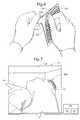
- FIG. 16is a top perspective view of a patch assembly according to further embodiments of the present invention.
- FIG. 17is a top plan view of a patch according to further embodiments of the present invention.
- FIG. 18is a top plan view of a patch according to further embodiments of the present invention.
- FIG. 19is a top plan view of a patch according to further embodiments of the present invention.
- FIG. 20is a top plan view of a base layer according to further embodiments of the present invention, wherein a portion of the base layer is partially removed.
- FIG. 21is a top perspective view of a patch according to further embodiments of the present invention, wherein a tab or component thereof is partially removed.
- FIG. 22is a top perspective view of the patch of FIG. 21 , wherein a group of tabs thereof is partially removed.
- FIG. 23is a plan view of a patch according to further embodiments of the present invention.
- FIG. 24is a plan view of a patch according to further embodiments of the present invention mounted on a patient's head.
- FIG. 25is a fragmentary, perspective view of a top layer including MRI-visible tabs according to further embodiments of the present invention.
- FIG. 26is a fragmentary, plan view of a base layer according to further embodiments of the present invention mounted on a patient's head and wherein a portion of the base layer is partially removed.
- FIG. 27is a plan view of a patch system according to embodiments of the present invention mounted on a patient.
- FIG. 28is a data processing system according to embodiments of the present invention.
- spatially relative termssuch as “under”, “below”, “lower”, “over”, “upper” and the like, may be used herein for ease of description to describe one element or feature's relationship to another element(s) or feature(s) as illustrated in the figures. It will be understood that the spatially relative terms are intended to encompass different orientations of the device in use or operation in addition to the orientation depicted in the figures. For example, if the device in the figures is inverted, elements described as “under” or “beneath” other elements or features would then be oriented “over” the other elements or features. Thus, the exemplary term “under” can encompass both an orientation of “over” and “under”.
- the devicemay be otherwise oriented (rotated 90 degrees or at other orientations) and the spatially relative descriptors used herein interpreted accordingly.
- the terms “upwardly”, “downwardly”, “vertical”, “horizontal” and the likeare used herein for the purpose of explanation only unless specifically indicated otherwise.
- Exemplary embodimentsare described below with reference to block diagrams and/or flowchart illustrations of methods, apparatus (systems and/or devices) and/or computer program products. It is understood that a block of the block diagrams and/or flowchart illustrations, and combinations of blocks in the block diagrams and/or flowchart illustrations, can be implemented by computer program instructions. These computer program instructions may be provided to a processor of a general purpose computer, special purpose computer, and/or other programmable data processing apparatus to produce a machine, such that the instructions, which execute via the processor of the computer and/or other programmable data processing apparatus, create means (functionality) and/or structure for implementing the functions/acts specified in the block diagrams and/or flowchart block or blocks.
- These computer program instructionsmay also be stored in a computer-readable memory that can direct a computer or other programmable data processing apparatus to function in a particular manner, such that the instructions stored in the computer-readable memory produce an article of manufacture including instructions which implement the functions/acts specified in the block diagrams and/or flowchart block or blocks.
- the computer program instructionsmay also be loaded onto a computer or other programmable data processing apparatus to cause a series of operational steps to be performed on the computer or other programmable apparatus to produce a computer-implemented process such that the instructions which execute on the computer or other programmable apparatus provide steps for implementing the functions/acts specified in the block diagrams and/or flowchart block or blocks.
- exemplary embodimentsmay be implemented in hardware and/or in software (including firmware, resident software, micro-code, etc.). Furthermore, exemplary embodiments may take the form of a computer program product on a computer-usable or computer-readable storage medium having computer-usable or computer-readable program code embodied in the medium for use by or in connection with an instruction execution system.
- a computer-usable or computer-readable mediummay be any medium that can contain, store, communicate, propagate, or transport the program for use by or in connection with the instruction execution system, apparatus, or device.
- the computer-usable or computer-readable mediummay be, for example but not limited to, an electronic, magnetic, optical, electromagnetic, infrared, or semiconductor system, apparatus, device, or propagation medium. More specific examples (a non-exhaustive list) of the computer-readable medium would include the following: an electrical connection having one or more wires, a portable computer diskette, a random access memory (RAM), a read-only memory (ROM), an erasable programmable read-only memory (EPROM or Flash memory), an optical fiber, and a portable compact disc read-only memory (CD-ROM).
- RAMrandom access memory
- ROMread-only memory
- EPROM or Flash memoryerasable programmable read-only memory
- CD-ROMportable compact disc read-only memory
- the computer-usable or computer-readable mediumcould even be paper or another suitable medium upon which the program is printed, as the program can be electronically captured, via, for instance, optical scanning of the paper or other medium, then compiled, interpreted, or otherwise processed in a suitable manner, if necessary, and then stored in a computer memory.
- Computer program code for carrying out operations of data processing systems discussed hereinmay be written in a high-level programming language, such as Java, AJAX (Asynchronous JavaScript), C, and/or C++, for development convenience.
- computer program code for carrying out operations of exemplary embodimentsmay also be written in other programming languages, such as, but not limited to, interpreted languages.
- Some modules or routinesmay be written in assembly language or even micro-code to enhance performance and/or memory usage.
- embodimentsare not limited to a particular programming language. It will be further appreciated that the functionality of any or all of the program modules may also be implemented using discrete hardware components, one or more application specific integrated circuits (ASICs), or a programmed digital signal processor or microcontroller.
- ASICsapplication specific integrated circuits
- each block in the flow charts or block diagramsrepresents a module, segment, or portion of code, which comprises one or more executable instructions for implementing the specified logical function(s).
- the functions noted in the blocksmay occur out of the order noted in the figures. For example, two blocks shown in succession may in fact be executed substantially.
- MRI-visiblemeans that a device or feature thereof is visible, directly or indirectly, in an MRI image.
- the visibilitymay be indicated by the increased SNR of the MRI signal proximate to the device (the device can act as an MRI receive antenna to collect signal from local tissue) and/or that the device actually generates MRI signal itself, such as via suitable hydro-based coatings and/or fluid (typically aqueous solutions) filled cavities.
- MRI-compatiblemeans that a device is safe for use in an MRI environment and/or can operate as intended in an MRI environment, and, as such, if residing within the high-field strength region of the magnetic field, is typically made of a non-ferromagnetic MRI-compatible material(s) suitable to reside and/or operate in a high magnetic field environment.
- facial markerrefers to a marker that can be identified visually and/or using electronic image recognition, electronic interrogation of MRI image data, or three-dimensional electrical signals to define a position and/or find the feature or component in 3-D space.
- Patches in accordance with embodiments of the present inventioncan be configured to identify or designate a location on a body.
- the locationmay be identified in order to determine a desired position, orientation or operation of a guide apparatus.
- the guide apparatusmay be used to guide and/or place diagnostic or interventional devices and/or therapies to any desired internal region of the body or object using MRI and/or in an MRI scanner or MRI interventional suite.
- the objectcan be any object, and may be particularly suitable for animal and/or human subjects.
- the guide apparatusis used to place implantable DBS leads for brain stimulation, typically deep brain stimulation.
- the guide apparatuscan be configured to deliver tools or therapies that stimulate a desired region of the sympathetic nerve chain.
- the interventional toolscan be configured to facilitate high resolution imaging via intrabody imaging coils (receive antennas), and/or the interventional tools can be configured to stimulate local tissue, which can facilitate confirmation of proper location by generating a physiologic feedback (observed physical reaction or via fMRI).
- the patchis used to identify a location on the body for delivering bions, stem cells or other target cells to site-specific regions in the body, such as neurological target and the like.
- the patchis used to identify a location on the body for introducing stem cells and/or other cardio-rebuilding cells or products into cardiac tissue, such as a heart wall via a minimally invasive MRI-guided procedure, while the heart is beating (i.e., not requiring a non-beating heart with the patient on a heart-lung machine). Examples of known stimulation treatments and/or target body regions are described in U.S. Pat. Nos.
- some embodiments of the inventionare directed to MRI interventional procedures including locally placing interventional tools or therapies in vivo to site-specific regions using an MRI system.
- the interventional toolscan be used to define an MRI-guided trajectory or access path to an in vivo treatment site.
- MRIcan be used to visualize (and/or locate) a therapeutic region of interest inside the brain or other body locations, to visualize an MRI-visible patch according to embodiments of the present invention, and to visualize (and/or locate) an interventional tool or tools that will be used to deliver therapy and/or to place a chronically implanted device that will deliver one or more therapies. Then, using the three-dimensional data produced by the MRI system regarding the location of the therapeutic region of interest and the location of the interventional tool, the system and/or physician can make positional adjustments to the interventional tool so as to align the trajectory of the interventional tool, so that when inserted into the body, the interventional tool will intersect with the therapeutic region of interest. With the interventional tool now aligned with the therapeutic region of interest, an interventional probe can be advanced, such as through an open lumen inside of the interventional tool, so that the interventional probe follows the trajectory of the interventional tool and proceeds to the therapeutic region of interest.
- a methodfor identifying a physical location on a body surface (e.g., the scalp) of a patient.
- a patchis provided including a flexible base layer that is mountable on and substantially conformable to the body surface and has opposed upper and lower primary surfaces, a flexible substrate that is releasably attached to the upper primary surface of the base layer and substantially conformable to the body surface, and a plurality of MRI-visible fiducial elements defined by or secured to the flexible substrate (Block 60 ).
- the MRI-visible fiducial elementsare arranged in a defined pattern.
- the patchis mounted on the body surface such that the flexible substrate conforms to the body surface (Block 62 ).
- Some embodiments of the present inventioninclude a computer program product comprising computer usable program code embodied in a computer usable medium and configured to programmatically execute the step of identifying the physical location on the body surface using the image data.
- a methodfor identifying a physical location on a body surface of a patient using a patch mounted on the body surface.
- the patchincludes a plurality of MRI-visible fiducial elements arranged in a defined pattern.
- An image of the patient and the patch in a logical spaceis generated (Block 70 ).
- the imagecorresponds to an MRI scan of the patient with the patch on the body surface.
- a desired trajectory line for insertion of instrumentation into the patientis determined in the logical space (Block 72 ).
- a location of intersection between the desired trajectory line and the patchis programmatically determined (Block 74 ). In some embodiments, the location of intersection is visually displayed.
- Some embodiments of the present inventioninclude a computer program product comprising computer usable program code embodied in a computer usable medium and configured to programmatically determine the location of intersection between the desired trajectory line and the patch.
- the patch assembly 101includes a patch 100 and a release liner 102 .
- the patch 100includes a base substrate or layer 110 , a primary or base adhesive 120 , an MRI-visible or top substrate or layer 130 , and a secondary or top adhesive 122 .
- the base layer 110has opposed upper and lower primary surfaces 112 A, 112 B.
- the base adhesive 120coats the lower primary surface 112 B.
- the release liner 102is releasably adhered to the base layer 110 by the base adhesive 120 , which remains with the base layer 110 when the release liner 102 is removed.
- the release line 102may include a pull tab 102 A.
- the base layer 110may include a pull tab 114 free of the adhesive 120 .
- the base layer 110is formed of a flexible material. According to some embodiments, the base layer 110 is formed of a biocompatible polymeric material suitable for surgical use in MRI systems. Suitable polymeric materials may include polyvinyl, PET, silicone, polyethylene, polyurethane, and/or polyamide.
- the base layer 110has a thickness in the range of from about 0.001 to 0.100 inches. According to some embodiments, the base layer 110 has a total area in the range of from about 1 to 900 cm 2 .
- the base adhesive 120is a biocompatible adhesive that has adhesive properties that ensure a secure, but releasable, bond with human skin and/or an incise drape.
- the top layer 130has an integral, bilayer construction including an inner layer 134 and an outer layer 136 .
- the top layer 130has a lower surface that is coated with the top adhesive 122 .
- the top layer 130includes a pull tab 138 extending beyond an edge thereof. A portion or all of the pull tab 138 may be free of the adhesive 122 .
- the outer layer 136is attached to the inner layer 134 at seams 144 ( FIG. 4 ) to form a plurality of discrete pockets or cavities 142 ( FIG. 4 ) between the seams 144 and the layers 134 , 136 .
- the layers 134 , 136may be attached via any suitable means such as bonded by adhesive, heat bonding or any other suitable technique.
- Each pocket 142is filled with a mass 146 ( FIG. 4 ) of an MRI-visible material 146 to form a respective MRI-visible fiducial element, bubble or tab 140 .
- the plurality of tabs 140can be arranged in a predefined array 168 and include a reference tab 140 R ( FIG. 3 ) positioned or shaped to be readily discerned with respect to the other tabs.
- MRI-visible tabs 140 , 140 Rare illustrated and described, other types and construction of MRI-visible fiducial elements may be employed in accordance with further embodiments.
- the reference tab 140 Rmay be replaced or supplemented with an MRI-visible coating.
- the layers 134 , 136are formed of a flexible material. According to some embodiments, the layers 134 , 136 are formed of a polymeric material. Suitable polymeric materials may include polyvinyl, PET, silicone, polyethylene, polyurethane, and/or polyamide.
- the MRI-visible material 146may be any suitable material. According to some embodiments, the MRI-visible material 146 is a liquid. According to some embodiments, the MRI-visible material 146 includes sterile saline or water (e.g., deionized water), with or without vitamin E and/or Gadolidium.
- sterile saline or watere.g., deionized water
- each pocket 142has a volume in the range of about 50 to 500 microliters. According to some embodiments, each pocket 142 has a nominal height in the range of from about 0.010 to 1 inch. According to some embodiments, each pocket 142 has an area in the range of from about 4 mm 2 to 4 cm 2 .
- the top layer 130has a nominal thickness in the range of from about 0.001 to 0.1 inch. According to some embodiments, the top layer 130 has a total area in the range of from about 1 to 900 cm 2 .
- the top adhesive 122is a biocompatible adhesive that has adhesive properties that ensure a secure, but releasable bond with base layer 110 .
- the MRI-visible tabs 140can be arranged in a defined pattern 163 ( FIG. 3 ).
- the defined pattern 163is a grid pattern, wherein the grid is demarcated by the voids between the masses 146 of MRI-visible material (generally, the seams 144 ).
- the defined pattern 163defines a coordinate system 161 .
- the coordinate system 161may be codified in any suitable manner. For example, as illustrated, letter indicia 164 (i.e., “A” to “J”) are provided to designate respective rows of the tabs 140 and number indicia 166 (i.e., “1” to “10”) are provided to designate respective columns of the tabs 140 in the coordinate system 161 .
- letter indicia 164i.e., “A” to “J”
- number indicia 166i.e., “1” to “10”
- other markings or indicators as well as other languagesmay be used.
- the predefined tab array 168includes a grouping of at least five-by-five tabs 140 .
- the reference tab 140 R of the tab array 140is positioned to indicate an orientation of the top layer 130 .
- the reference tab 140 R(or other reference MRI-visible fiducial element) has a shape that is discernibly dissimilar from the other tabs 140 in an MR image.
- the reference tab 140 Rmay not be positioned to indicate the orientation, but rather the orientation may be indicated by the orientation of the reference tab 140 R.
- Base indicia 150( FIG. 5 ) can be provided on the base layer 110 and define a prescribed pattern and a corresponding coordinate system 151 that in turn corresponds to the coordinate system 161 .
- the base indiciamay be provided on the base layer 110 by etching, printing, molding, embossing, stamping, pressing or any other suitable technique.
- the base indicia 150include grid lines 152 defining a matrix or grid 153 of sectors 152 A.
- Letter indicia 154i.e., “A” to “J” are provided to designate respective rows of the sectors 152 A and number indicia 156 (i.e., “1” to “10”) are provided to designate respective columns of the sectors 152 A.
- Four subsector marks 158(as shown, cross-hairs or grid lines) are provided in each sector 152 A to designate quadrants of the sector 152 A.
- the indicia 154 , 156serve as codified indicia representing or corresponding to the coordinate system 161 of the tab array 168 .
- Each of the sectors 152 Amay be sized and positioned to substantially coextensively align with a respective matched or overlying one of the tabs 140 .
- the prescribed pattern of the base indicia 150has higher resolution than the defined pattern of the array 168 of MRI-visible tabs 140 because the base indicia 150 further include the subsector marks 158 in each sector 152 A.
- FIGS. 6-15Operations associated with an exemplary surgical procedure using the patch assembly 101 , according to some embodiments of the present invention, will now be described with further reference to FIGS. 6-15 . These operations relate to deep brain stimulation procedures. Embodiments of the present invention are not limited to use with deep brain stimulation procedures, however, and may be suitable for other surgical uses including robotic or other type of intrabody surgeries.
- the operationsmay be executed on a head 12 of a patient 10 using a patch assembly 101 as described above and an interventional system 15 .
- the system 15includes or is in communication with an MRI scanner 20 , a display 22 , an electronic controller 24 , a user interface 26 , a trajectory guide apparatus 44 ( FIG. 15 ), and a device controller 44 A ( FIG. 15 ).
- the controller 24may include a trajectory guide module 24 B and a patch recognition module 24 A (which may be software or firmware modules, for example).
- the controller 24may be any suitable computer(s) or the like adapted to carry out the functions described herein.
- the user interface 26may include a man-machine interface to enable an operator to access and control operations of the system 15 .
- the controller 24can be operably connected to each of the display 22 and the MRI scanner 20 .
- the surface of the patient's head 12is suitably prepared by shaving and cleaning, for example.
- the release liner 102is peeled away from the base layer 110 to expose the base adhesive 120 ( FIG. 6 ).
- the patch 100is applied to the surface of the head 12 such that the flexible layers 110 , 134 , 136 conform to the head surface and the patch 100 is adhered to the head surface by the base adhesive 120 ( FIG. 7 ).
- An incise drape or the likemay be pre-applied to the skin surface and the patch 100 in turn applied to the incise drape, in which case the patch 110 may likewise be regarded as being mounted on the surface of the head (albeit indirectly).
- the patch 100is applied at a location such that the grid pattern 161 spans the region wherein the operator expects to enter the head 12 with an interventional tool or device.
- the patientWith the patch 100 adhered to the patient's head 12 , the patient is placed within an MRI scanner 20 .
- the MRI scannerscans the head 12 and generates corresponding MR image data.
- MR imagesare obtained of the patient's head that visualize the patient's skull and brain.
- the MR imagesalso visualize the MRI-visible masses 146 of the patch 100 , which serve as MRI-visible landmarks.
- the MR imagescan include volumetric high-resolution images of the brain.
- a target region TR(which may also be referred to as a region of interest or target therapeutic site) in the head 12 is identified in the MR images.
- certain known anatomical landmarkscan be used. For example, reference may be made to physiological landmarks such as the AC, PC and MCP points (brain atlases give the location of different anatomies in the brain with respect to these points) and other anatomical landmarks of the patient's head.
- a target point TP within the target region TRis selected and designated in a logical space in the MR image.
- a planned trajectory line PTLis selected and designated extending from the target point TP to a desired reference point (such as an operative pivot point of the trajectory guide apparatus 44 discussed hereinbelow).
- the planned trajectory line PTLextends through an entry surface of the head 12 at a desired entry location point EP in the logical space.
- the pivot pointis located at or proximate the entry location point EP. Images are obtained in the planned plane of trajectory to confirm that the trajectory is viable (i.e., that no complications with anatomically sensitive areas should occur).
- the steps of identifying the target region TR, identifying the target point TP, and/or selecting and designating the planned trajectory line PTLmay be executed using or with the aid of the trajectory guide module 24 B, for example.
- a point of intersection IP between the logical planned trajectory line PTL and the patch 100 in the logical spaceis determined. More particularly, according to some embodiments, the point of intersection IP between the planned trajectory line PTL and the array 168 of MRI-visible masses 146 is determined.
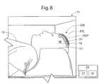
- the intersection point IPmay be determined by visually displaying the same on the display 22 where it can be readily identified by the operator (for example, as shown in FIG. 9A ).
- a representation or highlight of the planned trajectory line PTL and/or the intersection point IPcan be programmatically determined by the controller 24 and overlaid or projected onto an image 30 of the tab array 168 .
- the image 30may further include the MR image of the patient and/or an overlaid representation of the target point TP.
- the operatorcan determine the coordinates of the intersected tab 140 by determining the row number and column number of the tab 140 in the array 168 ( FIG. 1 ), for example.
- controller 24may programmatically identify or recognize and analyze and/or report the MRI-visible masses 146 in the image data.
- the controller 24processes the acquired image data to programmatically recognize, orient and place the patch 100 in the logical space.
- the controller 24uses an algorithm to programmatically determine the position of the tab array 168 in the logical space.
- the controlleruses a pre-stored reference image or images to programmatically determine the position of the tab array 168 in the logical space.
- the controller 24can use this data to identify the intersection point IP or enable or assist identification of the intersection point IP by the operator. For example, the controller 24 may enhance (e.g., add increased image contrast) or insert highlighted representations of the tabs 140 into the image 30 as provided on the display 22 in order to make the intersected tab 140 and/or the tab array 168 visually stand out in the image 30 .
- the controller 24generates, fits and overlays or superimposes a graphical grid overlay 31 onto the MR image 30 as shown in FIG. 9B , for example, to delineate the location and distribution of the patch 100 on the head.
- the positions and orientations of the patch 100 and the MRI-visible tabmay be correlated to the image of the head 12 by the graphical grid overlay 31 .
- the graphical grid overlay 31is fitted to the contours of the patch 100 in three dimensional space as illustrated, for example. This may be accomplished by segmenting the image of the tab array 168 and incorporating assessed angle data (of the edges of the tabs 140 ) in the process of drawing and fitting the graphical grid overlay 31 .
- the controller 24may determine and report or indicate the coordinates from the grid 163 corresponding to the intersection point IP to the operator (e.g., visually via the display 22 and/or audibly via a sound transducer).
- the intersection point IPis located in the MRI-visible tab 140 located in column 5 and row C of the grid 163 , and the graphical representation of the intersection point IP is labeled in the image 30 with these coordinates (as illustrated, “(7, D)”, designating the tab 140 at column “7” and row “D”) and a graphic overlay 32 .
- the operator and/or the controller 24can also determine the portion or region (e.g., quadrant) of the tab 140 within which the intersection point IP resides.
- the reference tab 140 Rcan be identified in the image 30 and used by the operator and/or the controller 24 to determine and register the orientation of the coordinate system 161 of the patch 100 in the logical (i.e., MR volume) frame of reference.
- the controller 24can provide various additional functionality once it has recognized the tab array 168 in the MR image 30 . According to some embodiments, the controller 24 will issue an alert (e.g., visible or audible) to the operator if the planned trajectory line PTL does not intersect the grid 163 . According to some embodiments, the controller 24 will initially position a provisional planned trajectory line through the center of the grid 163 . The operator can then move the provisional planned trajectory line in the display as needed to arrive at the desired ultimate planned trajectory line PTL.
- an alerte.g., visible or audible
- the physical location on the top layer 130 corresponding to the intersection point IPcan be readily determined using the image from the MR image data (e.g., by comparison to the image of the tabs 140 in the MR image and/or by reference to the coordinate system 161 ). Because the top layer 130 is affixed to the head 12 and the relationship between the patient's scalp and the MRI-visible tabs 140 is thereby maintained, the physical location of the intersection point IP (and, thus, the entry location point EP) can likewise be readily identified.
- the thickness of the patch 100 between the tabs 140 and the underlying surface of the head 12is thin (e.g., no more than 0.003 and 0.100 inch) so that the intersection point IP between the planned trajectory line PTL and the array 168 is substantially the same or closely proximate the intersection point between the planned trajectory line PTL and the surface of the head 12 .
- the patientcan be withdrawn from the scanning apparatus 20 to facilitate access to the patient's head 12 .
- the operatorremoves the top layer 130 from the base layer 110 to reveal the base layer 110 by lifting an edge of the top layer 130 and peeling the top layer 130 away from the base layer 110 as shown in FIG. 10 , for example.
- the operatoridentifies the location (referred to herein as the label point LP) on the base layer 110 corresponding to the location of the intersection point IP in the top layer 130 .
- This identificationmay be enabled by a prescribed correspondence between the coordinate system 151 of the base layer 110 and the array 168 of MRI-visible tabs 140 ( FIG. 5 ).
- the operatormay determine that the intersection point IP was located in the top, right quadrant of the tab 140 located at column “5”, row “C” of the array 168 .
- the operatorcan, in the present step, locate the quadrant located in the top, right quadrant of the square sector 152 A ( FIG.
- the coordinate system 151( FIG. 5 ) located at column “5”, row “C” of the coordinate system 151 and identify this quadrant as the corresponding label point LP.
- the coordinate system 151( FIG. 5 ) is readily legible on the base layer 110 so that the operator can expeditiously and reliably identify the label point LP without special tools or cumbersome procedure.
- the operatormay thereafter mark the head 12 at a location on the head surface corresponding to the label point LP.
- the operatormarks the head surface at a location immediately below the label point LP. It will be appreciated that this location on the head surface is substantially the same as the intended entry location point EP designated above for the planned trajectory line PTL.
- the patch 100thus can provide precise correlation between the logical points in the scanned MR volume and the physical patient.
- the operatorcan mark the head 12 at or proximate the desired entry location using a suitable tool or implement.
- a suitable tool or implementthe operator uses a marking tool 40 in the form of a driver.
- the operatorpresses the marking tool 40 into the patient's head 12 such that the marking tool 40 penetrates through the skin and may partially penetrate into the skull.
- the marking tool 40may be driven through the base layer 110 and into the head 12 .
- the operatormay lift or remove a portion of the base layer 110 to expose the location on the scalp to be marked and then mark the scalp.
- a visually identifiable mark 14FIG. 13
- Suitable marking toolsmay include marking tools as disclosed in co-assigned U.S. Provisional Patent Application No. 61/041,500, the disclosure of which is incorporated herein by reference.
- the operatormay mark the scalp with ink or other suitable material.
- the base layer 110is removed (e.g., peeled away) from the head 12 as shown in FIG. 12 .
- a burr hole 16( FIG. 14 ) can thereafter be formed in the head 12 at the location of the mark 14 using any suitable technique or device (e.g., drilling).
- a burr hole ring 42( FIG. 14 ) may be affixed to the skull 12 overlying the burr hole 16 .
- the proceduremay thereafter be continued using the burr hole 16 as an access portal to the brain and employing suitable instrumentation such as the trajectory guide apparatus 44 .
- the trajectory guide apparatus 44can be fixed to the skull of the patient as shown in FIG. 15 , for example.
- the trajectory guide apparatus 44may allow the operator to align an access path trajectory to the internal target site TP, such that the interventional/surgical device/lead, therapy, etc. will be delivered to the target site following the desired trajectory (e.g., the planned trajectory line PTL) through the cranial tissue. This trajectory goes through the entry location point EP.
- the desired trajectorye.g., the planned trajectory line PTL
- the interventional devicee.g., probe, lead or the like
- the interventional devicecan be advanced through a targeting cannula 44 B of the trajectory guide apparatus 44 , into the head 12 and to or proximate the target point TP.
- the trajectory guide apparatus 44can pivot the targeting cannula 44 B about a pivot point at or proximate the entry point location EP.
- the trajectory guide apparatus 44may be remotely repositioned using a trajectory guide apparatus controller 44 A, for example.
- Suitable trajectory guide apparatus and methodsmay include those disclosed in co-assigned PCT Application No. PCT/US2006/045752 and co-assigned U.S. patent application Ser. No. 12/134,412, the disclosures of which are incorporated herein by reference.
- the controller 24is in communication with a graphical user interface (GUT) that allows a clinician to define a desired trajectory and/or end position on a displayed image, then can electronically convert the orientation/site input data programmatically to generate position data for the trajectory guide apparatus 44 .
- the GUIcan include an interactive tool that allows a clinician to draw, trace or otherwise select and/or identify the target treatment site and/or access path trajectory.
- the system 15can then be configured to identify adjustments to the trajectory guide apparatus 44 that are most likely to achieve this trajectory.
- the user interface 26can be configured to electronically determine the location of a targeting cannula and a trajectory associated therewith.
- the user interface 26can be configured to display MRI images with the planned trajectory and intersection point(s) that will be followed if the interventional/surgical device/lead is advanced using a defined position of the trajectory guide apparatus 44 .
- the patch assembly 101is packaged as a medical kit with the marking tool 40 .
- the patch assembly 101may be used in conjunction with a burr hole forming tool (e.g., a drill) configured to drill, cut or otherwise form a burr hole through the patient's skull 12 .
- a burr hole forming toole.g., a drill
- the marking tool 40 and the burr hole forming toolare formed of MRI-compatible materials.
- a patch assembly 201according to further embodiments of the present invention is shown therein.
- the patch assembly 201corresponds to the patch assembly 101 except that the tabs 240 C of the center row and the center column of the tab array 268 have a geometric shape (as shown, circular) different than the geometric shape (as shown, rectangular) of the remaining tabs 240 .
- the respective shapesare distinguishable from one another when observed in the MR image. This combination of dissimilar tab shapes may assist the operator or controller 24 in identifying the location of the tab 240 or 240 C intersecting the planned trajectory line PTL.
- patches 300 , 400 , 500according to further embodiments of the present invention are shown therein.
- the patches 300 , 400 , 500each correspond to the patch 100 except that they further include perforations extending through the top layers 330 , 430 , 530 thereof between the tabs 340 , 440 , or 540 .
- the perforationsmay be configured as closed slits 339 , circular holes 439 , or open, elongated slots 539 . In use, the perforations may help the top layer 330 , 430 , 530 to conform to the patient's head.
- the base layers 310 , 410 , 510may also include perforations (e.g., extending along the grid lines) to help the base layer 310 , 410 , 510 conform to the patient's head. According to some embodiments, reliefs that do not extend fully through the top layer 330 , 430 , 530 may be used in place of the perforations.
- the base layer 610may be used in place of the base layer 110 for the patch 100 , for example, and corresponds to the base layer 110 except as follows.
- the base layer 610can include a grid of perforations 614 generally coextensive with the grid of the base coordinate system 651 .
- the base layer 610may be used in the same manner as the base layer 110 except that the operator may selectively tear away or remove a section of the base layer 610 along the perforations 614 in order to expose the underlying scalp for marking with the marking tool.
- the base layer 110may be rendered frangible by score lines or other suitable features.
- a patch 700according to further embodiments of the present invention is shown therein.
- the patch 700corresponds to the patch 100 except that the tabs 740 thereof can be removed individually or in subgroups from the remainder or the top layer 730 .
- the operatorcan remove a selected one or ones of the tabs 740 from the patient's head to reveal the underlying base layer 710 .
- the base layer 710may also be frangible (e.g., including perforations corresponding to the perforations 614 ), in which case the underlying segment of the base layer 710 may also be selectively removed to expose the patient's scalp for marking.
- Indicia 755may be visible on the base layer 710 where the tabs 740 have been removed.
- a patch 800according to further embodiments of the present invention is shown therein.
- the patch 800may correspond to the patch 100 except that the tab array 868 of the patch 800 includes rows of MRI-visible tabs 840 G, 840 H, 840 I having distinctly different geometric shapes (as shown, a circular shape, a square shape, and a triangular shape, respectively).
- the different tab shapesare discernable from an MR image of the patch 800 by an operator and/or the controller 24 .
- the configuration of the tab array 868may facilitate determination of the orientation of the patch 100 in logical space and/or identification of the tab 840 G, 840 H, 840 I intersected by the planned trajectory line PTL.
- the patch 900may correspond to the patch 100 except that the patch 900 includes a mesh (“fishnet”) substrate 930 to which an array 968 of MRI-visible tabs 940 (corresponding to the tabs 140 ) are secured.
- the substrate 930can be elastic or stretchable to readily deform or conform to the contours of a head 12 .
- the patch 900may be used in the same manner as the patch 100 except that in some embodiments the patch 900 may not include any base layer corresponding to the base layer 110 .
- the operatormay identify and mark the desired location (e.g., the point of intersection IP) through the openings 930 A of the mesh substrate 930 and the mesh substrate 930 may be adhered directly to the head (or an incise drape) by adhesive on the back surface of the mesh substrate 930 .
- the controller 24may recognize and assess the tab array 968 and construct a modified grid in logical space that corresponds to the distorted or irregular distribution of the tabs 940 caused by the stretching of substrate 930 .
- the controller 24may recognize and assess the tab array 968 and construct a modified grid in logical space that corresponds to the distorted or irregular distribution of the tabs 940 caused by the stretching of the substrate 930 .
- the layers 110 and 130 of the patch 100may be stretchable (with or without being meshes) to enable similar stretchable conformability to the head 12 .
- a top layer 1030according to further embodiments of the present invention is shown therein.
- the top layer 1030may be used in place of the top layer 130 , for example.
- the top layer 1030differs from the top layer 130 in that the top layer 1030 includes MRI-visible tabs 1040 each having a height dimension H 1 greater than its width W 1 .
- the height of each tab 1040is sufficient to permit the controller 24 and/or an operator to determine the orientation of a heightwise axis AH-AH of the tab 1040 . This additional information can be employed to more accurately assess the point of intersection IP with the planned trajectory line PTL.
- a base layer 1110according to further embodiments of the present invention is shown therein.
- the base layer 1110may be used in place of the base layer 110 or the base layer 610 , for example.
- the base layer 1110differs from the base layer 610 in that the base layer 1110 includes a supply of ink 1180 therein and/or thereon.
- the ink 1180transfers to the head 12 to leave an ink pattern 1182 on the surface of the head.
- the ink pattern 1182can include a full or partial duplicate 1182 A of the grid lines 1152 on the base layer 1110 and/or textual or codified indicia 1182 B indicating the coordinates.
- the base layer 1110can be used in the same manner as the base layer 110 or the base layer 610 except that the base layer 1110 can be fully or partially removed prior to marking the head 12 with a marking tool or the like.
- the ink pattern 1182remains on the scalp to assist the operator in marking the physical location corresponding to the intersection point IP determined from the MR image 30 .
- the ink 1180may be any suitable material that can transfer from the base layer 1110 to the patient's scalp, bond or adhere to the scalp, and provide a suitably visible contrast with the scalp.
- the inkmay be a liquid or powder, for example.
- the ink supplymay be provided in or on the substrate including the MRI-visible tabs (e.g., the top layer 130 ) in which case the base layer (e.g., the base layer 110 ) can be omitted.
- the substratecan be removed after the MRI scan is taken, leaving the ink pattern on the scalp of the head 12 to provide the reference grid on the head 12 for locating the physical location of the intersection point IP.
- the patch system 1203includes a plurality of the patches 100 , for example, applied to the patient 12 in close proximity to one another to form a patch array 1208 .
- the patches 100may be tiled together (i.e., placed in close proximity to one another) and may or may not be immediately adjacent one another or overlapping.
- the patch system 1203may be used in generally the same manner as the patch 100 as described above, except that the patch system 1203 will cover a greater surface area on the patient and only one of the patches 100 thereof will be intersected by the planned trajectory line PTL.
- the operatormay visually determine which of the patches contains the intersection point IP and where the intersection point IP lies in the patch.
- the controller 24programmatically assesses the patch system 1203 in the MR image to determine and indicate, report or otherwise process the positions of the patches 100 as discussed above with regard to the patch 100 .
- the controller 24may correlate the plurality of patches 100 with respect to one another so that the patch system 1203 can be assessed and processed in substantially the same manner as the single patch 100 .
- the controller 24may programmatically account for variations resulting from relative placements of the patches 100 in the patch array 1208 .
- the controller 24determines the orientation of each patch 100 using each patch's respective reference tab 140 R as described above.
- a flexible substrate having selectively removable MRI-visible tabsmay be provided without a base layer (e.g., the base layer 710 ) and may be directly applied to a patient's body surface or incise drape.
- a patchmay be provided having a base layer (e.g., corresponding to the base layer 110 ) and a removable top layer (e.g., corresponding to the top layer 130 ), but wherein the top layer carries only a single (i.e., exactly one) MRI-visible fiducial element or tab.
- the single MRI-visible fiducial elementmay have an asymmetric shape that is discernable in an MRI image so that the orientation of the patch in the logical space can be determined from the MRI image data.
- the orientation of a patch (with or without a base layer) having only a single MRI-visible fiducial elementis programmatically determined (e.g., by the controller 24 ) from the MRI image data.
- the patch(with our without a base layer) may have a plurality of MRI-visible fiducial elements, but wherein the fiducial elements are not arranged in a defined pattern.
- Two patches (or groups of patches) in accordance with the present inventioncan be employed together to identify and mark two entry location points for a bilateral surgical procedure on a patient's head.
- the two patches 100may be concurrently mounted on the head and each patch used in the same manner as discussed above.
- the controller 24may programmatically distinguish between the two patches and their respective planned trajectory lines PTL so that the point of intersection IP for each patch can be determined independently of the other.
- the controller 24may simultaneously display the patches 100 and their associated points of intersection IP, planned trajectory lines PTL, graphical overlays and the like.
- the system 15can include circuits or modules that can comprise computer program code used to automatically or semi-automatically carry out operations to generate multi-dimensional visualizations during an MRI guided therapy.
- FIG. 28is a schematic illustration of a circuit or data processing system 80 that can be used with the system 15 .
- the circuits and/or data processing systems 80 data processing systemsmay be incorporated in a digital signal processor in any suitable device or devices.
- the processor 82communicates with an MRI scanner 20 and with memory 84 via an address/data bus 85 .
- the processor 82can be any commercially available or custom microprocessor.
- the memory 84is representative of the overall hierarchy of memory devices containing the software and data used to implement the functionality of the data processing system.
- the memory 84can include, but is not limited to, the following types of devices: cache, ROM, PROM, EPROM, EEPROM, flash memory, SRAM, and DRAM.
- the memory 84may include several categories of software and data used in the data processing system: the operating system 86 ; the application programs 88 ; the input/output (I/O) device drivers 92 ; and data 90 .
- the data 90can also include tool and patient-specific image data 90 A.
- FIG. 28also illustrates the application programs 88 can include the patch recognition module 24 A and the trajectory guide module 24 B.
- the operating systems 452may be any operating system suitable for use with a data processing system, such as OS/2, AIX, DOS, OS/390 or System390 from International Business Machines Corporation, Armonk, N.Y., Windows CE, Windows NT, Windows95, Windows98, Windows2000 or other Windows versions from Microsoft Corporation, Redmond, Wash., Unix or Linux or FreeBSD, Palm OS from Palm, Inc., Mac OS from Apple Computer, LabView, or proprietary operating systems.
- the I/O device drivers 92typically include software routines accessed through the operating system 86 by the application programs 88 to communicate with devices such as I/O data port(s), data storage 90 and certain memory 84 components.
- the application programs 88are illustrative of the programs that implement the various features of the data processing system and can include at least one application, which supports operations according to embodiments of the present invention.
- the data 90represents the static and dynamic data used by the application programs 88 , the operating system 86 , the I/O device drivers 92 , and other software programs that may reside in the memory 84 .
- modules 24 A- 24 Bbeing application programs in FIG. 28
- the modules 24 A, 24 B and/ormay also be incorporated into the operating system 86 , the I/O device drivers 92 or other such logical division of the data processing system.
- the present inventionshould not be construed as limited to the configuration of FIG. 28 which is intended to encompass any configuration capable of carrying out the operations described herein.
- one or more of modules, i.e., modules 24 A, 24 Bcan communicate with or be incorporated totally or partially in other components, such as an MRI scanner.
- the I/O data portcan be used to transfer information between the data processing system, the MRI scanner, the tool and another computer system or a network (e.g., the Internet) or to other devices controlled by the processor.
- These componentsmay be conventional components such as those used in many conventional data processing systems, which may be configured in accordance with the present invention to operate as described herein.
Landscapes
- Health & Medical Sciences (AREA)
- Physics & Mathematics (AREA)
- Life Sciences & Earth Sciences (AREA)
- Surgery (AREA)
- General Health & Medical Sciences (AREA)
- General Physics & Mathematics (AREA)
- Pathology (AREA)
- Condensed Matter Physics & Semiconductors (AREA)
- Biomedical Technology (AREA)
- Oral & Maxillofacial Surgery (AREA)
- Engineering & Computer Science (AREA)
- Nuclear Medicine, Radiotherapy & Molecular Imaging (AREA)
- Heart & Thoracic Surgery (AREA)
- Medical Informatics (AREA)
- Molecular Biology (AREA)
- Animal Behavior & Ethology (AREA)
- Public Health (AREA)
- Veterinary Medicine (AREA)
- Magnetic Resonance Imaging Apparatus (AREA)
Abstract
Description
Claims (29)
Priority Applications (5)
| Application Number | Priority Date | Filing Date | Title |
|---|---|---|---|
| CA2700531ACA2700531A1 (en) | 2007-09-24 | 2008-09-24 | Mri-compatible patches and methods for using the same |
| PCT/US2008/011078WO2009042155A2 (en) | 2007-09-24 | 2008-09-24 | Mri-compatible patches and methods for using the same |
| EP08833040.2AEP2192871B8 (en) | 2007-09-24 | 2008-09-24 | Mri-compatible patch and method for identifying a position |
| US12/236,621US8195272B2 (en) | 2007-09-24 | 2008-09-24 | MRI-compatible patches and methods for using the same |
| US13/460,776US8644906B2 (en) | 2007-09-24 | 2012-04-30 | Methods for using MRI-compatible patches |
Applications Claiming Priority (2)
| Application Number | Priority Date | Filing Date | Title |
|---|---|---|---|
| US97482107P | 2007-09-24 | 2007-09-24 | |
| US12/236,621US8195272B2 (en) | 2007-09-24 | 2008-09-24 | MRI-compatible patches and methods for using the same |
Related Child Applications (1)
| Application Number | Title | Priority Date | Filing Date |
|---|---|---|---|
| US13/460,776DivisionUS8644906B2 (en) | 2007-09-24 | 2012-04-30 | Methods for using MRI-compatible patches |
Publications (2)
| Publication Number | Publication Date |
|---|---|
| US20090177077A1 US20090177077A1 (en) | 2009-07-09 |
| US8195272B2true US8195272B2 (en) | 2012-06-05 |
Family
ID=40512061
Family Applications (2)
| Application Number | Title | Priority Date | Filing Date |
|---|---|---|---|
| US12/236,621Active2030-12-05US8195272B2 (en) | 2007-09-24 | 2008-09-24 | MRI-compatible patches and methods for using the same |
| US13/460,776ActiveUS8644906B2 (en) | 2007-09-24 | 2012-04-30 | Methods for using MRI-compatible patches |
Family Applications After (1)
| Application Number | Title | Priority Date | Filing Date |
|---|---|---|---|
| US13/460,776ActiveUS8644906B2 (en) | 2007-09-24 | 2012-04-30 | Methods for using MRI-compatible patches |
Country Status (4)
| Country | Link |
|---|---|
| US (2) | US8195272B2 (en) |
| EP (1) | EP2192871B8 (en) |
| CA (1) | CA2700531A1 (en) |
| WO (1) | WO2009042155A2 (en) |
Cited By (36)
| Publication number | Priority date | Publication date | Assignee | Title |
|---|---|---|---|---|
| US8315689B2 (en) | 2007-09-24 | 2012-11-20 | MRI Interventions, Inc. | MRI surgical systems for real-time visualizations using MRI image data and predefined data of surgical tools |
| US20140094678A1 (en)* | 2012-09-28 | 2014-04-03 | Beekley Corporation | Skin Marking Porous Grid and Related Method of Use |
| US8979871B2 (en) | 2009-08-13 | 2015-03-17 | Monteris Medical Corporation | Image-guided therapy of a tissue |
| US9333038B2 (en) | 2000-06-15 | 2016-05-10 | Monteris Medical Corporation | Hyperthermia treatment and probe therefore |
| US9433383B2 (en) | 2014-03-18 | 2016-09-06 | Monteris Medical Corporation | Image-guided therapy of a tissue |
| US20160278865A1 (en)* | 2015-03-19 | 2016-09-29 | Medtronic Navigation, Inc. | Flexible Skin Based Patient Tracker For Optical Navigation |
| US9498290B2 (en) | 2012-07-19 | 2016-11-22 | MRI Interventions, Inc. | Surgical navigation devices and methods |
| US9504484B2 (en) | 2014-03-18 | 2016-11-29 | Monteris Medical Corporation | Image-guided therapy of a tissue |
| WO2016200967A1 (en)* | 2015-06-08 | 2016-12-15 | Medicomp, Inc | Non-invasive system and method of spatial localization of specific electrocardiac elements |
| US20170352457A1 (en)* | 2016-06-07 | 2017-12-07 | Ricoh Company, Ltd. | Marker coil and marker coil unit |
| US9891296B2 (en) | 2013-09-13 | 2018-02-13 | MRI Interventions, Inc. | Intrabody fluid transfer devices, systems and methods |
| USD824027S1 (en) | 2016-01-13 | 2018-07-24 | MRI Interventions, Inc. | Fins for a support column for a surgical trajectory frame |
| USD829904S1 (en) | 2016-01-13 | 2018-10-02 | MRI Interventions, Inc. | Curved bracket for surgical navigation systems |
| US10105485B2 (en) | 2010-04-16 | 2018-10-23 | MRI Interventions, Inc. | MRI surgical systems including MRI-compatible surgical cannulae for transferring a substance to and/or from a patient |
| WO2018194800A1 (en) | 2017-04-21 | 2018-10-25 | MRI Interventions, Inc. | Surgical navigation systems and related methods |
| US10327830B2 (en) | 2015-04-01 | 2019-06-25 | Monteris Medical Corporation | Cryotherapy, thermal therapy, temperature modulation therapy, and probe apparatus therefor |
| US10376333B2 (en) | 2016-01-14 | 2019-08-13 | MRI Interventions, Inc. | Devices for surgical navigation systems |
| US10426375B2 (en) | 2016-08-30 | 2019-10-01 | The Regents Of The University Of California | Methods for biomedical targeting and delivery and devices and systems for practicing the same |
| US10576247B2 (en) | 2016-02-17 | 2020-03-03 | MRI Interventions, Inc. | Intrabody surgical fluid transfer assemblies with adjustable exposed cannula to needle tip length, related systems and methods |
| US10575756B2 (en) | 2014-05-14 | 2020-03-03 | Stryker European Holdings I, Llc | Navigation system for and method of tracking the position of a work target |
| US10595744B2 (en) | 2014-02-14 | 2020-03-24 | MRI Interventions, Inc. | Surgical tool-positioning devices and related methods |
| US10675113B2 (en) | 2014-03-18 | 2020-06-09 | Monteris Medical Corporation | Automated therapy of a three-dimensional tissue region |
| US10743941B2 (en)* | 2015-11-24 | 2020-08-18 | Vanderbilt University | Method and system for trackerless image guided soft tissue surgery and applications of same |
| US11022664B2 (en) | 2018-05-09 | 2021-06-01 | Clearpoint Neuro, Inc. | MRI compatible intrabody fluid transfer systems and related devices and methods |
| WO2021150434A1 (en) | 2020-01-22 | 2021-07-29 | Clearpoint Neuro, Inc. | Surgical tool support systems including frame mount assemblies and related methods |
| WO2021154574A1 (en) | 2020-01-31 | 2021-08-05 | Clearpoint Neuro, Inc. | Surgical tool support systems including elongate support legs with adjustable lengths and related methods |
| WO2021183295A2 (en) | 2020-03-12 | 2021-09-16 | Clearpoint Neuro, Inc. | Image-guided surgical systems with automated trajectory guide systems and related devices and methods |
| US11253237B2 (en) | 2018-05-09 | 2022-02-22 | Clearpoint Neuro, Inc. | MRI compatible intrabody fluid transfer systems and related devices and methods |
| US20220305296A1 (en)* | 2019-05-24 | 2022-09-29 | The University Of Melbourne | Neurostimulation using endoluminal focussed ultrasound |
| US11497576B2 (en) | 2017-07-17 | 2022-11-15 | Voyager Therapeutics, Inc. | Trajectory array guide system |
| US11684750B2 (en) | 2019-10-08 | 2023-06-27 | Clearpoint Neuro, Inc. | Extension tube assembly and related medical fluid transfer systems and methods |
| US11701188B2 (en) | 2017-05-10 | 2023-07-18 | Mako Surgical Corp. | Robotic spine surgery system and methods |
| EP4025149A4 (en)* | 2019-09-05 | 2023-08-30 | Children's National Medical Center | SYSTEM, METHOD AND DEVICE FOR PERFORMING AN ARTHROGRAPHY |
| US20230326059A1 (en)* | 2020-12-17 | 2023-10-12 | Brainlab Ag | Patterned incision foil and method for determining a geometry of an anatomical surface |
| US12087429B2 (en) | 2020-04-30 | 2024-09-10 | Clearpoint Neuro, Inc. | Surgical planning systems that automatically assess different potential trajectory paths and identify candidate trajectories for surgical systems |
| US12102489B2 (en) | 2021-06-30 | 2024-10-01 | Clearpoint Neuro, Inc. | Image-guided surgical systems with quantitative evaluation of in vivo thermal treatments and related methods |
Families Citing this family (34)
| Publication number | Priority date | Publication date | Assignee | Title |
|---|---|---|---|---|
| PL2023812T3 (en) | 2006-05-19 | 2017-07-31 | The Queen's Medical Center | Motion tracking system for real time adaptive imaging and spectroscopy |
| WO2009067205A1 (en)* | 2007-11-21 | 2009-05-28 | Surgi-Vision, Inc. | Methods, systems and computer program products for positioning a guidance apparatus relative to a patient |
| US20100198052A1 (en)* | 2009-01-28 | 2010-08-05 | Kimble Jenkins | Mri-compatible articulating arms and related systems and methods |
| US8579922B2 (en)* | 2009-10-05 | 2013-11-12 | Covidien Lp | Method of suture identification and mesh marking for orienting and locating a mesh during hernia repair |
| DE102010023027A1 (en)* | 2010-06-08 | 2011-12-08 | Hans-Udo Eickenberg | Method for identifying and detecting non-intact area in testing object or pathological area in body, involves generating digital image data of non-intact area or diseased tissue area and its environment by magnetic resonance spectroscopy |
| WO2013032933A2 (en) | 2011-08-26 | 2013-03-07 | Kinecticor, Inc. | Methods, systems, and devices for intra-scan motion correction |
| WO2014032171A1 (en)* | 2012-08-27 | 2014-03-06 | Target Tape Inc. | Medical procedure localizing aid |
| CN109008972A (en) | 2013-02-01 | 2018-12-18 | 凯内蒂科尔股份有限公司 | The motion tracking system of real-time adaptive motion compensation in biomedical imaging |
| US20150011866A1 (en)* | 2013-06-11 | 2015-01-08 | Adventist Health System/Sunbelt, Inc. | Probe for Surgical Navigation |
| CA2918879A1 (en) | 2013-07-24 | 2015-01-29 | Centre For Surgical Invention & Innovation | Multi-function mounting interface for an image-guided robotic system and quick release interventional toolset |
| US10111714B2 (en)* | 2014-01-27 | 2018-10-30 | Align Technology, Inc. | Adhesive objects for improving image registration of intraoral images |
| EP3188660A4 (en) | 2014-07-23 | 2018-05-16 | Kineticor, Inc. | Systems, devices, and methods for tracking and compensating for patient motion during a medical imaging scan |
| WO2016034364A1 (en)* | 2014-09-01 | 2016-03-10 | Koninklijke Philips N.V. | Magnetic resonance imaging receive coil with reduced radiation attenuation |
| CA3020520A1 (en)* | 2015-04-13 | 2016-10-20 | Accumetra, Llc | Table top image calibration phantom |
| GB2569114B (en) | 2015-05-08 | 2020-12-16 | Synaptive Medical Barbados Inc | Magnetic resonance visible labels and markers for encoding information |
| CN104799954B (en)* | 2015-05-15 | 2017-10-10 | 徐州英杰医疗科技有限公司 | Medical film positions the production technology of patch in vitro |
| US20170303859A1 (en)* | 2016-04-26 | 2017-10-26 | Kineticor, Inc. | Systems, devices, and methods for tracking and compensating for patient motion during a medical imaging scan |
| KR101864992B1 (en)* | 2017-03-09 | 2018-07-04 | 국립암센터 | Composition for removing noise in MRI and pad using the same |
| US11571262B2 (en)* | 2017-04-18 | 2023-02-07 | Intuitive Surgical Operations, Inc. | Graphical user interface for planning a procedure |
| WO2019060058A1 (en)* | 2017-09-21 | 2019-03-28 | Medtronic, Inc. | Imaging markers for stimulator leads |
| CN107874845A (en)* | 2017-10-27 | 2018-04-06 | 郑鹏锋 | A kind of novel encephalic lesion scalp positioning rule patch |
| CN108440265B (en)* | 2018-04-26 | 2021-12-07 | 中国科学院理化技术研究所 | Synthetic method and application of chemical shift reagent |
| WO2020154448A1 (en) | 2019-01-23 | 2020-07-30 | Eloupes, Inc. | Aligning pre-operative scan images to real-time operative images for a mediated-reality view of a surgical site |
| WO2020167200A1 (en)* | 2019-02-14 | 2020-08-20 | Prismatic Sensors Ab | Calibration of an x-ray imaging system |
| DE102019133421A1 (en)* | 2019-12-06 | 2021-06-10 | InLine-Med GmbH | Needle guide device and set with several elements |
| US20210318397A1 (en) | 2020-04-08 | 2021-10-14 | Clearpoint Neuro, Inc. | Mri surgical systems including mri-compatible surgical cannulas for transferring a substance to and/or from a patient |
| WO2022132282A1 (en) | 2020-12-14 | 2022-06-23 | Clearpoint Neuro, Inc. | Surgical base assemblies for trajectory guide systems and associated trajectory guide systems |
| US20220183766A1 (en)* | 2020-12-15 | 2022-06-16 | Mazor Robotics Ltd. | Systems and methods for defining a work volume |
| US11612364B2 (en) | 2021-01-06 | 2023-03-28 | Bradley Hammett | Longitudinal-positioning indicator and marking grid |
| WO2022177636A1 (en)* | 2021-02-22 | 2022-08-25 | Fresenius Medical Care Holdings, Inc. | System and method for measuring edema at home and measurement pattern for use therewith |
| DE102021125935A1 (en) | 2021-10-06 | 2023-04-06 | InLine-Med GmbH | Device for covering a body part of a patient |
| JP2023081490A (en)* | 2021-12-01 | 2023-06-13 | 国立大学法人広島大学 | MRI imaging marker |
| WO2023191989A1 (en) | 2022-03-29 | 2023-10-05 | Clearpoint Neuro, Inc. | Surgical systems including flexible mri-compatible surgical catheters for transferring a substance to and/or from a brain of a patient |
| US20250082429A1 (en)* | 2023-09-11 | 2025-03-13 | MediVis, Inc. | Adhesive surgical reference marker unit |
Citations (86)
| Publication number | Priority date | Publication date | Assignee | Title |
|---|---|---|---|---|
| US4319136A (en) | 1979-11-09 | 1982-03-09 | Jinkins J Randolph | Computerized tomography radiograph data transfer cap |
| US4386602A (en) | 1977-05-17 | 1983-06-07 | Sheldon Charles H | Intracranial surgical operative apparatus |
| US4838265A (en) | 1985-05-24 | 1989-06-13 | Cosman Eric R | Localization device for probe placement under CT scanner imaging |
| US5052035A (en) | 1989-11-02 | 1991-09-24 | Webb Research Ii Corporation | Image location marking devices for radiographs, method of making and methods of use |
| US5125888A (en) | 1990-01-10 | 1992-06-30 | University Of Virginia Alumni Patents Foundation | Magnetic stereotactic system for treatment delivery |
| US5154723A (en) | 1987-12-02 | 1992-10-13 | Olympus Optical Co., Ltd. | Cerebral surgery apparatus |
| US5260985A (en) | 1992-08-14 | 1993-11-09 | Mosby Richard A | Conforming localization/biopsy grid and control apparatus |
| US5342356A (en) | 1992-12-02 | 1994-08-30 | Ellman Alan G | Electrical coupling unit for electrosurgery |
| US5427099A (en) | 1994-03-17 | 1995-06-27 | Adams; Timothy L. | Marker for magnetic resonance imaging |
| US5469847A (en) | 1992-09-09 | 1995-11-28 | Izi Corporation | Radiographic multi-modality skin markers |
| US5638819A (en) | 1995-08-29 | 1997-06-17 | Manwaring; Kim H. | Method and apparatus for guiding an instrument to a target |
| US5655084A (en) | 1993-11-26 | 1997-08-05 | Access Radiology Corporation | Radiological image interpretation apparatus and method |
| US5695501A (en) | 1994-09-30 | 1997-12-09 | Ohio Medical Instrument Company, Inc. | Apparatus for neurosurgical stereotactic procedures |
| US5697958A (en) | 1995-06-07 | 1997-12-16 | Intermedics, Inc. | Electromagnetic noise detector for implantable medical devices |
| US5699801A (en) | 1995-06-01 | 1997-12-23 | The Johns Hopkins University | Method of internal magnetic resonance imaging and spectroscopic analysis and associated apparatus |
| DE19625834A1 (en) | 1996-06-27 | 1998-01-02 | Siemens Ag | Medical system architecture |
| US5728079A (en) | 1994-09-19 | 1998-03-17 | Cordis Corporation | Catheter which is visible under MRI |
| US5743899A (en) | 1997-03-04 | 1998-04-28 | Izi Medical Products | Method and apparatus for marking skin with ink |
| US5776144A (en) | 1996-05-10 | 1998-07-07 | Implex Gmbh Spezialhorgerate | Device for positioning and fixing of therapeutic, surgical, or diagnostic instruments |
| WO1998052064A1 (en) | 1997-05-15 | 1998-11-19 | Regents Of The University Of Minnesota | Method and apparatus for targeted drug delivery into a living patient using magnetic resonance imaging |
| US5928145A (en) | 1996-04-25 | 1999-07-27 | The Johns Hopkins University | Method of magnetic resonance imaging and spectroscopic analysis and associated apparatus employing a loopless antenna |
| US5961455A (en) | 1996-12-31 | 1999-10-05 | Daum Gmbh | Device for positioning a medical instrument and method |
| US5993463A (en) | 1997-05-15 | 1999-11-30 | Regents Of The University Of Minnesota | Remote actuation of trajectory guide |
| US6006126A (en) | 1991-01-28 | 1999-12-21 | Cosman; Eric R. | System and method for stereotactic registration of image scan data |
| US6050992A (en) | 1997-05-19 | 2000-04-18 | Radiotherapeutics Corporation | Apparatus and method for treating tissue with multiple electrodes |
| US6119032A (en) | 1997-12-31 | 2000-09-12 | U.S. Philips Corporation | Method and system for positioning an invasive device by magnetic resonance (MR) imaging of an MR visible device |
| US6159497A (en)* | 1998-10-30 | 2000-12-12 | Noven Pharmaceuticals, Inc. | Patch applicator |
| US6167311A (en) | 1999-06-14 | 2000-12-26 | Electro Core Techniques, Llc | Method of treating psychological disorders by brain stimulation within the thalamus |
| US6167292A (en) | 1998-06-09 | 2000-12-26 | Integrated Surgical Systems Sa | Registering method and apparatus for robotic surgery, and a registering device constituting an application thereof |
| US6195577B1 (en) | 1998-10-08 | 2001-02-27 | Regents Of The University Of Minnesota | Method and apparatus for positioning a device in a body |
| US20010004676A1 (en) | 1999-12-14 | 2001-06-21 | Asahi Kogaku Kogyo Kabushiki Kaisha | Manipulating section for an endoscopic treatment instrument |
| US6263229B1 (en) | 1998-11-13 | 2001-07-17 | Johns Hopkins University School Of Medicine | Miniature magnetic resonance catheter coils and related methods |
| US6267769B1 (en) | 1997-05-15 | 2001-07-31 | Regents Of The Universitiy Of Minnesota | Trajectory guide method and apparatus for use in magnetic resonance and computerized tomographic scanners |
| US6273896B1 (en) | 1998-04-21 | 2001-08-14 | Neutar, Llc | Removable frames for stereotactic localization |
| US6282437B1 (en) | 1998-08-12 | 2001-08-28 | Neutar, Llc | Body-mounted sensing system for stereotactic surgery |
| US6284971B1 (en) | 1998-11-25 | 2001-09-04 | Johns Hopkins University School Of Medicine | Enhanced safety coaxial cables |
| US6298262B1 (en) | 1998-04-21 | 2001-10-02 | Neutar, Llc | Instrument guidance for stereotactic surgery |
| US20010053879A1 (en) | 2000-04-07 | 2001-12-20 | Mills Gerald W. | Robotic trajectory guide |
| DE10029736A1 (en) | 2000-06-23 | 2002-01-03 | Daum Gmbh I Ins | Minimally invasive neurosurgery insert is small clamped by |
| US20020010479A1 (en) | 2000-04-07 | 2002-01-24 | Skakoon James G. | Medical device introducer |
| US6351662B1 (en) | 1998-08-12 | 2002-02-26 | Neutar L.L.C. | Movable arm locator for stereotactic surgery |
| US6356786B1 (en) | 2000-01-20 | 2002-03-12 | Electrocore Techniques, Llc | Method of treating palmar hyperhydrosis by electrical stimulation of the sympathetic nervous chain |
| US20020049451A1 (en) | 2000-08-17 | 2002-04-25 | Kari Parmer | Trajectory guide with instrument immobilizer |
| US6405079B1 (en) | 2000-09-22 | 2002-06-11 | Mehdi M. Ansarinia | Stimulation method for the dural venous sinuses and adjacent dura for treatment of medical conditions |
| US6419680B1 (en) | 1993-06-10 | 2002-07-16 | Sherwood Services Ag | CT and MRI visible index markers for stereotactic localization |
| US6438423B1 (en) | 2000-01-20 | 2002-08-20 | Electrocore Technique, Llc | Method of treating complex regional pain syndromes by electrical stimulation of the sympathetic nerve chain |
| US20030028095A1 (en) | 1999-04-15 | 2003-02-06 | Steve Tulley | Magnetic resonance imaging probe |
| US6526318B1 (en) | 2000-06-16 | 2003-02-25 | Mehdi M. Ansarinia | Stimulation method for the sphenopalatine ganglia, sphenopalatine nerve, or vidian nerve for treatment of medical conditions |
| US6529765B1 (en) | 1998-04-21 | 2003-03-04 | Neutar L.L.C. | Instrumented and actuated guidance fixture for sterotactic surgery |
| US20030050557A1 (en) | 1998-11-04 | 2003-03-13 | Susil Robert C. | Systems and methods for magnetic-resonance-guided interventional procedures |
| US20030055436A1 (en) | 2001-09-14 | 2003-03-20 | Wolfgang Daum | Navigation of a medical instrument |
| US6539263B1 (en) | 1999-06-11 | 2003-03-25 | Cornell Research Foundation, Inc. | Feedback mechanism for deep brain stimulation |
| DE10029737A1 (en) | 2000-06-23 | 2003-05-22 | Mri Devices Daum Gmbh | Navigation of a medical instrument within the human body by use of a set of three or more markers attached to the instrument that are suitable for use with nuclear spin tomography and whereby the markers can be differentiated |
| US6584351B1 (en) | 1998-01-02 | 2003-06-24 | Pacesetter Ab | Implantable cardiac stimulator with circuitry for removing noise in sensed electrical signals |
| US20030120143A1 (en) | 1998-07-06 | 2003-06-26 | Neutar, Llc, A Maine Corporation | Customizable fixture for patient positioning |
| US6606513B2 (en) | 2000-02-01 | 2003-08-12 | Surgi-Vision, Inc. | Magnetic resonance imaging transseptal needle antenna |
| US6609030B1 (en) | 2000-02-24 | 2003-08-19 | Electrocore Techniques, Llc | Method of treating psychiatric diseases by neuromodulation within the dorsomedial thalamus |
| US6628980B2 (en) | 2000-03-24 | 2003-09-30 | Surgi-Vision, Inc. | Apparatus, systems, and methods for in vivo magnetic resonance imaging |
| US6675033B1 (en) | 1999-04-15 | 2004-01-06 | Johns Hopkins University School Of Medicine | Magnetic resonance imaging guidewire probe |
| US6701176B1 (en) | 1998-11-04 | 2004-03-02 | Johns Hopkins University School Of Medicine | Magnetic-resonance-guided imaging, electrophysiology, and ablation |
| US20040046557A1 (en) | 2002-05-29 | 2004-03-11 | Parag Karmarkar | Magnetic resonance probes |
| US6708064B2 (en) | 2000-02-24 | 2004-03-16 | Ali R. Rezai | Modulation of the brain to affect psychiatric disorders |
| US6725092B2 (en) | 2002-04-25 | 2004-04-20 | Biophan Technologies, Inc. | Electromagnetic radiation immune medical assist device adapter |
| US20040092810A1 (en) | 2002-02-14 | 2004-05-13 | Wolfgang Daum | Method and apparatus for MR-guided biopsy |
| US6752812B1 (en) | 1997-05-15 | 2004-06-22 | Regent Of The University Of Minnesota | Remote actuation of trajectory guide |
| US6772000B2 (en) | 2001-10-19 | 2004-08-03 | Scimed Life Systems, Inc. | Magnetic resonance imaging devices with a contrast medium for improved imaging |
| US20040167543A1 (en) | 2003-02-20 | 2004-08-26 | Mazzocchi Rudy A. | Trajectory guide with angled or patterned lumens or height adjustment |
| US20040215279A1 (en) | 2003-04-25 | 2004-10-28 | Houben Richard P.M. | Implantable lead-based sensor powered by piezoelectric transformer |
| US20050070781A1 (en) | 2003-04-28 | 2005-03-31 | Vanderbilt University | Electrophysiological atlas and applications of same |
| EP1524626A2 (en) | 2003-07-14 | 2005-04-20 | Sunnybrook & Women's College Health Sciences Centre | Optical image-based position tracking for magnetic resonance imaging |
| US6920347B2 (en) | 2000-04-07 | 2005-07-19 | Surgical Navigation Technologies, Inc. | Trajectory storage apparatus and method for surgical navigation systems |
| US20050193609A1 (en)* | 2004-02-27 | 2005-09-08 | Schwartz Janice B. | Medical information patch |
| US20050222647A1 (en) | 2004-03-30 | 2005-10-06 | Wahlstrand Carl D | Lead electrode for use in an MRI-safe implantable medical device |
| US20060195134A1 (en)* | 2005-02-28 | 2006-08-31 | Medtronic Vascular, Inc. | Device, system, and method for aiding valve annuloplasty |
| WO2006099475A2 (en) | 2005-03-15 | 2006-09-21 | Tdk Electronics Corporation | Medical archive library and method |
| US20060229641A1 (en) | 2005-01-28 | 2006-10-12 | Rajiv Gupta | Guidance and insertion system |
| US20060241400A1 (en) | 1990-10-19 | 2006-10-26 | St. Louis University | Method of determining the position of an instrument relative to a body of a patient |
| US20060252314A1 (en) | 2005-05-04 | 2006-11-09 | Ergin Atalar | Electrical lead for an electronic device such as an implantable device |
| US7155316B2 (en) | 2002-08-13 | 2006-12-26 | Microbotics Corporation | Microsurgical robot system |
| US20070106305A1 (en) | 2005-11-07 | 2007-05-10 | Vanderbilt University | Adjustable universal surgical platform |
| US7217276B2 (en) | 1999-04-20 | 2007-05-15 | Surgical Navigational Technologies, Inc. | Instrument guidance method and system for image guided surgery |
| US20070118049A1 (en) | 2000-09-11 | 2007-05-24 | Tyco Healthcare Group Lp | Biopsy system |
| US7241283B2 (en) | 2003-04-25 | 2007-07-10 | Ad-Tech Medical Instrument Corp. | Method for intracranial catheter treatment of brain tissue |
| WO2007106558A2 (en) | 2006-03-14 | 2007-09-20 | The Johns Hopkins University | Apparatus for insertion of a medical device within a body during a medical imaging process and devices and methods related thereto |
| US20080039709A1 (en) | 2004-08-09 | 2008-02-14 | Karmarkar Parag V | Implantable Mri compatible Stimulation Leads And Antennas And Related Systems And Methods |
| US20080306375A1 (en) | 2007-06-07 | 2008-12-11 | Surgi-Vision, Inc. | Mri-guided medical interventional systems and methods |
Family Cites Families (10)
| Publication number | Priority date | Publication date | Assignee | Title |
|---|---|---|---|---|
| US4150008A (en) | 1977-03-07 | 1979-04-17 | E. I. Du Pont De Nemours And Company | Fluorocarbon polymer-pigment coating compositions stabilized against discoloration |
| US5971997A (en)* | 1995-02-03 | 1999-10-26 | Radionics, Inc. | Intraoperative recalibration apparatus for stereotactic navigators |
| FR2764731A1 (en)* | 1997-06-13 | 1998-12-18 | Commissariat Energie Atomique | X-RAY TUBE COMPRISING A MICROPOINT ELECTRON SOURCE AND MAGNETIC FOCUSING MEANS |
| US6117143A (en) | 1998-09-11 | 2000-09-12 | Hybex Surgical Specialties, Inc. | Apparatus for frameless stereotactic surgery |
| JP2001161660A (en) | 1999-12-10 | 2001-06-19 | Hitachi Medical Corp | Magnetic resonance imaging system |
| US7020844B2 (en) | 2001-11-21 | 2006-03-28 | General Electric Company | Method and apparatus for managing workflow in prescribing and processing medical images |
| US20040164148A1 (en)* | 2003-01-13 | 2004-08-26 | Guanghua Qiu | System and method for identifying an object |
| ATE444712T1 (en) | 2004-05-21 | 2009-10-15 | Ethicon Endo Surgery Inc | MRI BIOPSY DEVICE WITH A DISPLAYABLE PENETRATION PART |
| CN101304775A (en) | 2005-09-12 | 2008-11-12 | 株式会社根本杏林堂 | Chemical liquid infusion system |
| EP1924198B1 (en) | 2005-09-13 | 2019-04-03 | Veran Medical Technologies, Inc. | Apparatus for image guided accuracy verification |
- 2008
- 2008-09-24USUS12/236,621patent/US8195272B2/enactiveActive
- 2008-09-24WOPCT/US2008/011078patent/WO2009042155A2/enactiveApplication Filing
- 2008-09-24EPEP08833040.2Apatent/EP2192871B8/enactiveActive
- 2008-09-24CACA2700531Apatent/CA2700531A1/ennot_activeAbandoned
- 2012
- 2012-04-30USUS13/460,776patent/US8644906B2/enactiveActive
Patent Citations (104)
| Publication number | Priority date | Publication date | Assignee | Title |
|---|---|---|---|---|
| US4386602A (en) | 1977-05-17 | 1983-06-07 | Sheldon Charles H | Intracranial surgical operative apparatus |
| US4319136A (en) | 1979-11-09 | 1982-03-09 | Jinkins J Randolph | Computerized tomography radiograph data transfer cap |
| US4838265A (en) | 1985-05-24 | 1989-06-13 | Cosman Eric R | Localization device for probe placement under CT scanner imaging |
| US5154723A (en) | 1987-12-02 | 1992-10-13 | Olympus Optical Co., Ltd. | Cerebral surgery apparatus |
| US5052035A (en) | 1989-11-02 | 1991-09-24 | Webb Research Ii Corporation | Image location marking devices for radiographs, method of making and methods of use |
| US6216030B1 (en) | 1990-01-10 | 2001-04-10 | The University Of Virginia Alumni Patents Foundation | Magnetic stereotactic system for treatment delivery |
| US5779694A (en) | 1990-01-10 | 1998-07-14 | The University Of Virginia Alumni Patents Foundation | Magnetic stereotactic system for treatment delivery |
| US5125888A (en) | 1990-01-10 | 1992-06-30 | University Of Virginia Alumni Patents Foundation | Magnetic stereotactic system for treatment delivery |
| US5707335A (en) | 1990-01-10 | 1998-01-13 | The University Of Virginia Alumni Patents Foundation | Magnetic stereotactic system and treatment delivery |
| US20060241400A1 (en) | 1990-10-19 | 2006-10-26 | St. Louis University | Method of determining the position of an instrument relative to a body of a patient |
| US6006126A (en) | 1991-01-28 | 1999-12-21 | Cosman; Eric R. | System and method for stereotactic registration of image scan data |
| US5260985A (en) | 1992-08-14 | 1993-11-09 | Mosby Richard A | Conforming localization/biopsy grid and control apparatus |
| US5469847A (en) | 1992-09-09 | 1995-11-28 | Izi Corporation | Radiographic multi-modality skin markers |
| US5342356A (en) | 1992-12-02 | 1994-08-30 | Ellman Alan G | Electrical coupling unit for electrosurgery |
| US6419680B1 (en) | 1993-06-10 | 2002-07-16 | Sherwood Services Ag | CT and MRI visible index markers for stereotactic localization |
| US5655084A (en) | 1993-11-26 | 1997-08-05 | Access Radiology Corporation | Radiological image interpretation apparatus and method |
| US5427099A (en) | 1994-03-17 | 1995-06-27 | Adams; Timothy L. | Marker for magnetic resonance imaging |
| US5728079A (en) | 1994-09-19 | 1998-03-17 | Cordis Corporation | Catheter which is visible under MRI |
| US5695501A (en) | 1994-09-30 | 1997-12-09 | Ohio Medical Instrument Company, Inc. | Apparatus for neurosurgical stereotactic procedures |
| US5699801A (en) | 1995-06-01 | 1997-12-23 | The Johns Hopkins University | Method of internal magnetic resonance imaging and spectroscopic analysis and associated apparatus |
| US5697958A (en) | 1995-06-07 | 1997-12-16 | Intermedics, Inc. | Electromagnetic noise detector for implantable medical devices |
| US5638819A (en) | 1995-08-29 | 1997-06-17 | Manwaring; Kim H. | Method and apparatus for guiding an instrument to a target |
| US5928145A (en) | 1996-04-25 | 1999-07-27 | The Johns Hopkins University | Method of magnetic resonance imaging and spectroscopic analysis and associated apparatus employing a loopless antenna |
| US5776144A (en) | 1996-05-10 | 1998-07-07 | Implex Gmbh Spezialhorgerate | Device for positioning and fixing of therapeutic, surgical, or diagnostic instruments |
| DE19625834A1 (en) | 1996-06-27 | 1998-01-02 | Siemens Ag | Medical system architecture |
| US5961455A (en) | 1996-12-31 | 1999-10-05 | Daum Gmbh | Device for positioning a medical instrument and method |
| US5743899A (en) | 1997-03-04 | 1998-04-28 | Izi Medical Products | Method and apparatus for marking skin with ink |
| US6206890B1 (en) | 1997-05-15 | 2001-03-27 | Regents Of The University Of Minnesota | Remote actuation of trajectory guide |
| US20020019641A1 (en) | 1997-05-15 | 2002-02-14 | Image-Guided Neurologics, Inc. | Trajectory guide |
| WO1998052064A1 (en) | 1997-05-15 | 1998-11-19 | Regents Of The University Of Minnesota | Method and apparatus for targeted drug delivery into a living patient using magnetic resonance imaging |
| US5993463A (en) | 1997-05-15 | 1999-11-30 | Regents Of The University Of Minnesota | Remote actuation of trajectory guide |
| US6752812B1 (en) | 1997-05-15 | 2004-06-22 | Regent Of The University Of Minnesota | Remote actuation of trajectory guide |
| US6368329B1 (en) | 1997-05-15 | 2002-04-09 | Regents Of The University Of Minnesota | Method of using trajectory guide |
| US6267770B1 (en) | 1997-05-15 | 2001-07-31 | Regents Of The University Of Minnesota | Remote actuation of trajectory guide |
| US6267769B1 (en) | 1997-05-15 | 2001-07-31 | Regents Of The Universitiy Of Minnesota | Trajectory guide method and apparatus for use in magnetic resonance and computerized tomographic scanners |
| US6050992A (en) | 1997-05-19 | 2000-04-18 | Radiotherapeutics Corporation | Apparatus and method for treating tissue with multiple electrodes |
| US6119032A (en) | 1997-12-31 | 2000-09-12 | U.S. Philips Corporation | Method and system for positioning an invasive device by magnetic resonance (MR) imaging of an MR visible device |
| US6584351B1 (en) | 1998-01-02 | 2003-06-24 | Pacesetter Ab | Implantable cardiac stimulator with circuitry for removing noise in sensed electrical signals |
| US6273896B1 (en) | 1998-04-21 | 2001-08-14 | Neutar, Llc | Removable frames for stereotactic localization |
| US6298262B1 (en) | 1998-04-21 | 2001-10-02 | Neutar, Llc | Instrument guidance for stereotactic surgery |
| US6529765B1 (en) | 1998-04-21 | 2003-03-04 | Neutar L.L.C. | Instrumented and actuated guidance fixture for sterotactic surgery |
| US6167292A (en) | 1998-06-09 | 2000-12-26 | Integrated Surgical Systems Sa | Registering method and apparatus for robotic surgery, and a registering device constituting an application thereof |
| US20030120143A1 (en) | 1998-07-06 | 2003-06-26 | Neutar, Llc, A Maine Corporation | Customizable fixture for patient positioning |
| US6282437B1 (en) | 1998-08-12 | 2001-08-28 | Neutar, Llc | Body-mounted sensing system for stereotactic surgery |
| US6351662B1 (en) | 1998-08-12 | 2002-02-26 | Neutar L.L.C. | Movable arm locator for stereotactic surgery |
| US20010014771A1 (en) | 1998-10-08 | 2001-08-16 | Regents Of The University Of Minnesota | Method and apparatus for positioning a device in a body |
| US6195577B1 (en) | 1998-10-08 | 2001-02-27 | Regents Of The University Of Minnesota | Method and apparatus for positioning a device in a body |
| US6782288B2 (en) | 1998-10-08 | 2004-08-24 | Regents Of The University Of Minnesota | Method and apparatus for positioning a device in a body |
| US6159497A (en)* | 1998-10-30 | 2000-12-12 | Noven Pharmaceuticals, Inc. | Patch applicator |
| US6701176B1 (en) | 1998-11-04 | 2004-03-02 | Johns Hopkins University School Of Medicine | Magnetic-resonance-guided imaging, electrophysiology, and ablation |
| US20030050557A1 (en) | 1998-11-04 | 2003-03-13 | Susil Robert C. | Systems and methods for magnetic-resonance-guided interventional procedures |
| US6263229B1 (en) | 1998-11-13 | 2001-07-17 | Johns Hopkins University School Of Medicine | Miniature magnetic resonance catheter coils and related methods |
| US6284971B1 (en) | 1998-11-25 | 2001-09-04 | Johns Hopkins University School Of Medicine | Enhanced safety coaxial cables |
| US6675033B1 (en) | 1999-04-15 | 2004-01-06 | Johns Hopkins University School Of Medicine | Magnetic resonance imaging guidewire probe |
| US20030028095A1 (en) | 1999-04-15 | 2003-02-06 | Steve Tulley | Magnetic resonance imaging probe |
| US7217276B2 (en) | 1999-04-20 | 2007-05-15 | Surgical Navigational Technologies, Inc. | Instrument guidance method and system for image guided surgery |
| US6539263B1 (en) | 1999-06-11 | 2003-03-25 | Cornell Research Foundation, Inc. | Feedback mechanism for deep brain stimulation |
| US6167311A (en) | 1999-06-14 | 2000-12-26 | Electro Core Techniques, Llc | Method of treating psychological disorders by brain stimulation within the thalamus |
| US20010004676A1 (en) | 1999-12-14 | 2001-06-21 | Asahi Kogaku Kogyo Kabushiki Kaisha | Manipulating section for an endoscopic treatment instrument |
| US6438423B1 (en) | 2000-01-20 | 2002-08-20 | Electrocore Technique, Llc | Method of treating complex regional pain syndromes by electrical stimulation of the sympathetic nerve chain |
| US6356786B1 (en) | 2000-01-20 | 2002-03-12 | Electrocore Techniques, Llc | Method of treating palmar hyperhydrosis by electrical stimulation of the sympathetic nervous chain |
| US6606513B2 (en) | 2000-02-01 | 2003-08-12 | Surgi-Vision, Inc. | Magnetic resonance imaging transseptal needle antenna |
| US6708064B2 (en) | 2000-02-24 | 2004-03-16 | Ali R. Rezai | Modulation of the brain to affect psychiatric disorders |
| US6609030B1 (en) | 2000-02-24 | 2003-08-19 | Electrocore Techniques, Llc | Method of treating psychiatric diseases by neuromodulation within the dorsomedial thalamus |
| US6628980B2 (en) | 2000-03-24 | 2003-09-30 | Surgi-Vision, Inc. | Apparatus, systems, and methods for in vivo magnetic resonance imaging |
| US20020052610A1 (en) | 2000-04-07 | 2002-05-02 | Skakoon James G. | Deep organ access device and method |
| US20010053879A1 (en) | 2000-04-07 | 2001-12-20 | Mills Gerald W. | Robotic trajectory guide |
| US6920347B2 (en) | 2000-04-07 | 2005-07-19 | Surgical Navigation Technologies, Inc. | Trajectory storage apparatus and method for surgical navigation systems |
| US7235084B2 (en) | 2000-04-07 | 2007-06-26 | Image-Guided Neurologics, Inc. | Deep organ access device and method |
| US20020010479A1 (en) | 2000-04-07 | 2002-01-24 | Skakoon James G. | Medical device introducer |
| US6526318B1 (en) | 2000-06-16 | 2003-02-25 | Mehdi M. Ansarinia | Stimulation method for the sphenopalatine ganglia, sphenopalatine nerve, or vidian nerve for treatment of medical conditions |
| DE10029737A1 (en) | 2000-06-23 | 2003-05-22 | Mri Devices Daum Gmbh | Navigation of a medical instrument within the human body by use of a set of three or more markers attached to the instrument that are suitable for use with nuclear spin tomography and whereby the markers can be differentiated |
| DE10029736A1 (en) | 2000-06-23 | 2002-01-03 | Daum Gmbh I Ins | Minimally invasive neurosurgery insert is small clamped by |
| US20020049451A1 (en) | 2000-08-17 | 2002-04-25 | Kari Parmer | Trajectory guide with instrument immobilizer |
| US20040267284A1 (en) | 2000-08-17 | 2004-12-30 | Image-Guided Neurologics, Inc. | Trajectory guide with instrument immobilizer |
| US20070118049A1 (en) | 2000-09-11 | 2007-05-24 | Tyco Healthcare Group Lp | Biopsy system |
| US6405079B1 (en) | 2000-09-22 | 2002-06-11 | Mehdi M. Ansarinia | Stimulation method for the dural venous sinuses and adjacent dura for treatment of medical conditions |
| US20040064148A1 (en) | 2001-09-14 | 2004-04-01 | Wolfgang Daum | Navigation of medical instrument |
| US20030055436A1 (en) | 2001-09-14 | 2003-03-20 | Wolfgang Daum | Navigation of a medical instrument |
| US6772000B2 (en) | 2001-10-19 | 2004-08-03 | Scimed Life Systems, Inc. | Magnetic resonance imaging devices with a contrast medium for improved imaging |
| US20040228796A1 (en) | 2001-10-19 | 2004-11-18 | Scimed Life Systems, Inc. | Magnetic resonance imaging devices with a contrast medium for improved imaging |
| US20040092810A1 (en) | 2002-02-14 | 2004-05-13 | Wolfgang Daum | Method and apparatus for MR-guided biopsy |
| US6725092B2 (en) | 2002-04-25 | 2004-04-20 | Biophan Technologies, Inc. | Electromagnetic radiation immune medical assist device adapter |
| US20040046557A1 (en) | 2002-05-29 | 2004-03-11 | Parag Karmarkar | Magnetic resonance probes |
| US6904307B2 (en) | 2002-05-29 | 2005-06-07 | Surgi-Vision, Inc. | Magnetic resonance probes |
| US7155316B2 (en) | 2002-08-13 | 2006-12-26 | Microbotics Corporation | Microsurgical robot system |
| US20040167543A1 (en) | 2003-02-20 | 2004-08-26 | Mazzocchi Rudy A. | Trajectory guide with angled or patterned lumens or height adjustment |
| US20060192319A1 (en) | 2003-02-20 | 2006-08-31 | Image-Guided Neurologics, Inc. | Trajectory guide with angled or patterned guide lumens or height adjustment |
| US20060195119A1 (en) | 2003-02-20 | 2006-08-31 | Image-Guided Neurologics, Inc. | Trajectory guide with angled or patterned guide lumens or height adjustment |
| US20040215279A1 (en) | 2003-04-25 | 2004-10-28 | Houben Richard P.M. | Implantable lead-based sensor powered by piezoelectric transformer |
| US7241283B2 (en) | 2003-04-25 | 2007-07-10 | Ad-Tech Medical Instrument Corp. | Method for intracranial catheter treatment of brain tissue |
| US20050070781A1 (en) | 2003-04-28 | 2005-03-31 | Vanderbilt University | Electrophysiological atlas and applications of same |
| US7167760B2 (en) | 2003-04-28 | 2007-01-23 | Vanderbilt University | Apparatus and methods of optimal placement of deep brain stimulator |
| EP1524626A2 (en) | 2003-07-14 | 2005-04-20 | Sunnybrook & Women's College Health Sciences Centre | Optical image-based position tracking for magnetic resonance imaging |
| US20050193609A1 (en)* | 2004-02-27 | 2005-09-08 | Schwartz Janice B. | Medical information patch |
| US20050222647A1 (en) | 2004-03-30 | 2005-10-06 | Wahlstrand Carl D | Lead electrode for use in an MRI-safe implantable medical device |
| US20080039709A1 (en) | 2004-08-09 | 2008-02-14 | Karmarkar Parag V | Implantable Mri compatible Stimulation Leads And Antennas And Related Systems And Methods |
| US20060229641A1 (en) | 2005-01-28 | 2006-10-12 | Rajiv Gupta | Guidance and insertion system |
| US20060195134A1 (en)* | 2005-02-28 | 2006-08-31 | Medtronic Vascular, Inc. | Device, system, and method for aiding valve annuloplasty |
| WO2006099475A2 (en) | 2005-03-15 | 2006-09-21 | Tdk Electronics Corporation | Medical archive library and method |
| US20060252314A1 (en) | 2005-05-04 | 2006-11-09 | Ergin Atalar | Electrical lead for an electronic device such as an implantable device |
| US20070106305A1 (en) | 2005-11-07 | 2007-05-10 | Vanderbilt University | Adjustable universal surgical platform |
| WO2007106558A2 (en) | 2006-03-14 | 2007-09-20 | The Johns Hopkins University | Apparatus for insertion of a medical device within a body during a medical imaging process and devices and methods related thereto |
| US20080306375A1 (en) | 2007-06-07 | 2008-12-11 | Surgi-Vision, Inc. | Mri-guided medical interventional systems and methods |
Non-Patent Citations (23)
| Title |
|---|
| Baker et al., Neurostimulation systems: assessment of magnetic field interactions associated with 1.5- and 3-Tesla MR systems, J Magn Reson Imaging, 2005, 72-77, 21(1). |
| Bhidayasiri et al., Bilateral neurostimulation systems used for deep brain stimulation: in vitro study of MRI-related heating at 1.5 T and implications for clinical imaging of the brain, Magn Reson Imaging, 2005, 549-555, 23(4). |
| Buchli et al., Increased RF power absorption in MR imaging due to RF coupling between body coil and surface coil, Magn Reson Med, 1989, 105-112, 9(1). |
| Dorward et al., Accuracy of true frameless stereotaxy: in vivo measurement and laboratory phantom studies, J. Neurosurg., 1999, 90:160-168. |
| Francel, Nexframe System, Bilateral Activa Lead Delivery to STN Using Nexframe, Oklahoma University Presbyterian Hospital, Image-Guided Neurolgics. |
| Grimson et al., An automatic registration method for frameless stereotaxy, image guided surgery, and visualization, IEEE Tran on Medical Imaging, Apr. 1996, 129-140. |
| Hall et al., Brian biopsy sampling by using prospective stereotaxis and a trajectory guide, J. Neurosurg., 2001, 94:67-71. |
| Invitation to Pay Additional Fees and, Where Applicable, Protest Fee (4 pages) corresponding to International Application No. PCT/US2008/011078; Mailing Date: Jan. 14, 2009. |
| Jorgensen, Erik, Brain Image Analsis Team Joins SCI Institute, http://www.sci.utah.edu/stories/2007/Gerig-NeuroimageAnalysis.html, (2007), 3 Pages. |
| Lin et al., "A Wavelet-Based Approximation of Surface Coil Sensitivity Profiles for Correction of Image Intensity Inhomogeneity and Parallel Imaging Reconstruction," Human Brain Mapping 2003, 19(2):96-111. |
| Liu et al., Remotely-Controlled Approach for Stereotactic Neurobiopsy, Computer Aided Surgery, 2002, 7:237-247. |
| Martin et al., "Placement of Deep Brain Stimulator Electrodes Using Real-Time High-Field Interventional Magnetic Resonance Imaging," Magnetic Resonance in Medicine, 54:1107-1114 (2005). |
| Martin et al., Placement of Deep Brain Stimulator Electrodes Using Real-Time High-Field Interventional Magnetic Resonance Imaging, Magnetic Resonance in Medicine, 2005, 54:1107-1114. |
| Sauser, Brittany, A 3-D View of the Brain, http://www.technologyreview.com/Biotech/19140, Aug. 6, 2007, 3 Pages. |
| Singh et al., "Accurate Intensity Correction for Endorectal Surface Coil MR Imaging of the Prostate," IEEE Transactions on Nuclear Science, 1993, 40(4):1169-1173. |
| Smith et al., The Neurostation-A Highly Accurate, Minimally Invasive Solution to Frameless Stereotactic Neurosurgery, Computerized Medical Imaging and Graphics, 1994, 247-256, 18(4). |
| STarFix(TM)-Dr. Joel Franck and FHC engineer Ron Franklin-creators, www.tgt.vanderbilt.edu/reu2/REU2002/chris.ppt. |
| STarFix™—Dr. Joel Franck and FHC engineer Ron Franklin—creators, www.tgt.vanderbilt.edu/reu2/REU2002/chris.ppt. |
| Tear Away Introducer Sets (INTRADYN), B. Braun Medical, Inc. http://www.bbraunusa.com. |
| Truwit et al., Prospective Stereotaxy: A Novel Method of Trajectory Alignment Using Real-Time Image Guidance, J. Magn. Reson. Imag., 2001, 13:452-457. |
| Willems et al., Frameless Stereotaxy, VHL Family Alliance, http://www.vhl.org/newsletter/vhl2000/00aefrst.htm. |
| Wirtz et al., Image-Guided Neurosurgery with Intraoperative MRI: Update of Frameless Stereotaxy and Radicality Control, Sterotact Funct Neurosurg 1997, 68:39-43. |
| Yoda, Decoupling technique for transmit coils in NMR spectroscopy and imaging, NMR Biomed, 1990, 27-30, 3(1). |
Cited By (75)
| Publication number | Priority date | Publication date | Assignee | Title |
|---|---|---|---|---|
| US9333038B2 (en) | 2000-06-15 | 2016-05-10 | Monteris Medical Corporation | Hyperthermia treatment and probe therefore |
| US9387042B2 (en) | 2000-06-15 | 2016-07-12 | Monteris Medical Corporation | Hyperthermia treatment and probe therefor |
| US10376327B2 (en) | 2007-09-24 | 2019-08-13 | MRI Interventions, Inc. | Computer programs for visualizations using image data and predefined data of surgical tools |
| US9314305B2 (en) | 2007-09-24 | 2016-04-19 | MRI Interventions, Inc. | Methods associated with MRI surgical systems for real-time visualizations using MRI image data and predefined data of surgical tools |
| US8315689B2 (en) | 2007-09-24 | 2012-11-20 | MRI Interventions, Inc. | MRI surgical systems for real-time visualizations using MRI image data and predefined data of surgical tools |
| US11317982B2 (en) | 2007-09-24 | 2022-05-03 | Clearpoint Neuro, Inc. | Image processing circuits for real-time visualizations using MRI image data and predefined data of surgical tools |
| US9271794B2 (en) | 2009-08-13 | 2016-03-01 | Monteris Medical Corporation | Monitoring and noise masking of thermal therapy |
| US8979871B2 (en) | 2009-08-13 | 2015-03-17 | Monteris Medical Corporation | Image-guided therapy of a tissue |
| US10610317B2 (en) | 2009-08-13 | 2020-04-07 | Monteris Medical Corporation | Image-guided therapy of a tissue |
| US9211157B2 (en) | 2009-08-13 | 2015-12-15 | Monteris Medical Corporation | Probe driver |
| US10188462B2 (en) | 2009-08-13 | 2019-01-29 | Monteris Medical Corporation | Image-guided therapy of a tissue |
| US9510909B2 (en) | 2009-08-13 | 2016-12-06 | Monteris Medical Corporation | Image-guide therapy of a tissue |
| US10105485B2 (en) | 2010-04-16 | 2018-10-23 | MRI Interventions, Inc. | MRI surgical systems including MRI-compatible surgical cannulae for transferring a substance to and/or from a patient |
| US11793933B2 (en) | 2010-04-16 | 2023-10-24 | Clearpoint Neuro, Inc. | MRI-compatible surgical cannulae for transferring a substance to and/or from a patient |
| US10569013B2 (en) | 2010-04-16 | 2020-02-25 | MRI Interventions, Inc. | MRI-compatible surgical cannulae for transferring a substance to and/or from a patient |
| US10548678B2 (en) | 2012-06-27 | 2020-02-04 | Monteris Medical Corporation | Method and device for effecting thermal therapy of a tissue |
| US10307220B2 (en) | 2012-07-19 | 2019-06-04 | MRI Interventions, Inc. | Surgical navigation devices and methods |
| US9498290B2 (en) | 2012-07-19 | 2016-11-22 | MRI Interventions, Inc. | Surgical navigation devices and methods |
| US20140094678A1 (en)* | 2012-09-28 | 2014-04-03 | Beekley Corporation | Skin Marking Porous Grid and Related Method of Use |
| US10143531B2 (en)* | 2012-09-28 | 2018-12-04 | Beekley Corporation | Skin marking porous grid and related method of use |
| US9891296B2 (en) | 2013-09-13 | 2018-02-13 | MRI Interventions, Inc. | Intrabody fluid transfer devices, systems and methods |
| US10595744B2 (en) | 2014-02-14 | 2020-03-24 | MRI Interventions, Inc. | Surgical tool-positioning devices and related methods |
| US9486170B2 (en) | 2014-03-18 | 2016-11-08 | Monteris Medical Corporation | Image-guided therapy of a tissue |
| US9492121B2 (en) | 2014-03-18 | 2016-11-15 | Monteris Medical Corporation | Image-guided therapy of a tissue |
| US10092367B2 (en) | 2014-03-18 | 2018-10-09 | Monteris Medical Corporation | Image-guided therapy of a tissue |
| US9700342B2 (en) | 2014-03-18 | 2017-07-11 | Monteris Medical Corporation | Image-guided therapy of a tissue |
| US9433383B2 (en) | 2014-03-18 | 2016-09-06 | Monteris Medical Corporation | Image-guided therapy of a tissue |
| US10342632B2 (en) | 2014-03-18 | 2019-07-09 | Monteris Medical Corporation | Image-guided therapy of a tissue |
| US10675113B2 (en) | 2014-03-18 | 2020-06-09 | Monteris Medical Corporation | Automated therapy of a three-dimensional tissue region |
| US9504484B2 (en) | 2014-03-18 | 2016-11-29 | Monteris Medical Corporation | Image-guided therapy of a tissue |
| US12408843B2 (en) | 2014-05-14 | 2025-09-09 | Stryker European Operations Holdings Llc | Navigation system for and method of tracking the position of a work target |
| US10575756B2 (en) | 2014-05-14 | 2020-03-03 | Stryker European Holdings I, Llc | Navigation system for and method of tracking the position of a work target |
| US11540742B2 (en) | 2014-05-14 | 2023-01-03 | Stryker European Operations Holdings Llc | Navigation system for and method of tracking the position of a work target |
| US10413377B2 (en)* | 2015-03-19 | 2019-09-17 | Medtronic Navigation, Inc. | Flexible skin based patient tracker for optical navigation |
| US20160278865A1 (en)* | 2015-03-19 | 2016-09-29 | Medtronic Navigation, Inc. | Flexible Skin Based Patient Tracker For Optical Navigation |
| US11672583B2 (en) | 2015-04-01 | 2023-06-13 | Monteris Medical Corporation | Cryotherapy, thermal therapy, temperature modulation therapy, and probe apparatus therefor |
| US10327830B2 (en) | 2015-04-01 | 2019-06-25 | Monteris Medical Corporation | Cryotherapy, thermal therapy, temperature modulation therapy, and probe apparatus therefor |
| US10772523B2 (en) | 2015-06-08 | 2020-09-15 | Medicomp, Inc. | Non-invasive system and method of spatial localization of specific electrocardiac elements |
| WO2016200967A1 (en)* | 2015-06-08 | 2016-12-15 | Medicomp, Inc | Non-invasive system and method of spatial localization of specific electrocardiac elements |
| US10743941B2 (en)* | 2015-11-24 | 2020-08-18 | Vanderbilt University | Method and system for trackerless image guided soft tissue surgery and applications of same |
| USD824027S1 (en) | 2016-01-13 | 2018-07-24 | MRI Interventions, Inc. | Fins for a support column for a surgical trajectory frame |
| USD910173S1 (en) | 2016-01-13 | 2021-02-09 | Clearpoint Neuro, Inc. | Curved bracket for surgical device |
| USD829904S1 (en) | 2016-01-13 | 2018-10-02 | MRI Interventions, Inc. | Curved bracket for surgical navigation systems |
| US10376333B2 (en) | 2016-01-14 | 2019-08-13 | MRI Interventions, Inc. | Devices for surgical navigation systems |
| US11253333B2 (en) | 2016-01-14 | 2022-02-22 | Clearpoint Neuro, Inc. | Devices for surgical navigation systems |
| US11541207B2 (en) | 2016-02-17 | 2023-01-03 | Clearpoint Neuro, Inc. | Intrabody surgical fluid transfer assemblies with adjustable exposed cannula to needle tip length, related systems and methods |
| US12390617B2 (en) | 2016-02-17 | 2025-08-19 | Clearpoint Neuro, Inc. | Intrabody surgical fluid transfer assemblies with adjustable exposed cannula to needle tip length, related systems and methods |
| US10576247B2 (en) | 2016-02-17 | 2020-03-03 | MRI Interventions, Inc. | Intrabody surgical fluid transfer assemblies with adjustable exposed cannula to needle tip length, related systems and methods |
| US20170352457A1 (en)* | 2016-06-07 | 2017-12-07 | Ricoh Company, Ltd. | Marker coil and marker coil unit |
| US11170921B2 (en)* | 2016-06-07 | 2021-11-09 | Ricoh Company, Ltd. | Marker coil and marker coil unit |
| US12318183B2 (en) | 2016-08-30 | 2025-06-03 | The Regents Of The University Of California | Methods for biomedical targeting and delivery and devices and systems for practicing the same |
| US10426374B2 (en) | 2016-08-30 | 2019-10-01 | The Regents Of The University Of California | Methods for biomedical targeting and delivery and devices and systems for practicing the same |
| US11298043B2 (en) | 2016-08-30 | 2022-04-12 | The Regents Of The University Of California | Methods for biomedical targeting and delivery and devices and systems for practicing the same |
| US11298041B2 (en) | 2016-08-30 | 2022-04-12 | The Regents Of The University Of California | Methods for biomedical targeting and delivery and devices and systems for practicing the same |
| US10426375B2 (en) | 2016-08-30 | 2019-10-01 | The Regents Of The University Of California | Methods for biomedical targeting and delivery and devices and systems for practicing the same |
| WO2018194800A1 (en) | 2017-04-21 | 2018-10-25 | MRI Interventions, Inc. | Surgical navigation systems and related methods |
| US10905497B2 (en) | 2017-04-21 | 2021-02-02 | Clearpoint Neuro, Inc. | Surgical navigation systems |
| US11779401B2 (en) | 2017-04-21 | 2023-10-10 | Clearpoint Neuro, Inc. | Methods for surgical navigation |
| US11701188B2 (en) | 2017-05-10 | 2023-07-18 | Mako Surgical Corp. | Robotic spine surgery system and methods |
| US12035985B2 (en) | 2017-05-10 | 2024-07-16 | Mako Surgical Corp. | Robotic spine surgery system and methods |
| US11497576B2 (en) | 2017-07-17 | 2022-11-15 | Voyager Therapeutics, Inc. | Trajectory array guide system |
| US11022664B2 (en) | 2018-05-09 | 2021-06-01 | Clearpoint Neuro, Inc. | MRI compatible intrabody fluid transfer systems and related devices and methods |
| US11253237B2 (en) | 2018-05-09 | 2022-02-22 | Clearpoint Neuro, Inc. | MRI compatible intrabody fluid transfer systems and related devices and methods |
| US20220305296A1 (en)* | 2019-05-24 | 2022-09-29 | The University Of Melbourne | Neurostimulation using endoluminal focussed ultrasound |
| US12343567B2 (en)* | 2019-05-24 | 2025-07-01 | The University Of Melbourne | Neurostimulation using endoluminal focussed ultrasound |
| EP4025149A4 (en)* | 2019-09-05 | 2023-08-30 | Children's National Medical Center | SYSTEM, METHOD AND DEVICE FOR PERFORMING AN ARTHROGRAPHY |
| US11684750B2 (en) | 2019-10-08 | 2023-06-27 | Clearpoint Neuro, Inc. | Extension tube assembly and related medical fluid transfer systems and methods |
| US12290643B2 (en) | 2019-10-08 | 2025-05-06 | Clearpoint Neuro, Inc. | Extension tube assembly and related medical fluid transfer systems and methods |
| WO2021150434A1 (en) | 2020-01-22 | 2021-07-29 | Clearpoint Neuro, Inc. | Surgical tool support systems including frame mount assemblies and related methods |
| US11925511B2 (en) | 2020-01-31 | 2024-03-12 | Clearpoint Neuro, Inc. | Surgical tool support systems including elongate support legs with adjustable lengths and related methods |
| WO2021154574A1 (en) | 2020-01-31 | 2021-08-05 | Clearpoint Neuro, Inc. | Surgical tool support systems including elongate support legs with adjustable lengths and related methods |
| WO2021183295A2 (en) | 2020-03-12 | 2021-09-16 | Clearpoint Neuro, Inc. | Image-guided surgical systems with automated trajectory guide systems and related devices and methods |
| US12087429B2 (en) | 2020-04-30 | 2024-09-10 | Clearpoint Neuro, Inc. | Surgical planning systems that automatically assess different potential trajectory paths and identify candidate trajectories for surgical systems |
| US20230326059A1 (en)* | 2020-12-17 | 2023-10-12 | Brainlab Ag | Patterned incision foil and method for determining a geometry of an anatomical surface |
| US12102489B2 (en) | 2021-06-30 | 2024-10-01 | Clearpoint Neuro, Inc. | Image-guided surgical systems with quantitative evaluation of in vivo thermal treatments and related methods |
Also Published As
| Publication number | Publication date |
|---|---|
| CA2700531A1 (en) | 2009-04-02 |
| EP2192871A2 (en) | 2010-06-09 |
| US8644906B2 (en) | 2014-02-04 |
| EP2192871B8 (en) | 2015-01-28 |
| WO2009042155A2 (en) | 2009-04-02 |
| EP2192871B1 (en) | 2014-11-19 |
| US20090177077A1 (en) | 2009-07-09 |
| WO2009042155A3 (en) | 2009-06-25 |
| US20120238864A1 (en) | 2012-09-20 |
Similar Documents
| Publication | Publication Date | Title |
|---|---|---|
| US8195272B2 (en) | MRI-compatible patches and methods for using the same | |
| US11779401B2 (en) | Methods for surgical navigation | |
| US20150011868A1 (en) | MRI-Compatible Fiducial Markers and Methods for Using the Same | |
| AU2003244333B2 (en) | Positioning system for neurological procedures in the brain | |
| US8340743B2 (en) | Methods, systems and computer program products for positioning a guidance apparatus relative to a patient | |
| US10307220B2 (en) | Surgical navigation devices and methods | |
| CA2931877C (en) | Trajectory guidance alignment system and methods | |
| US10413366B2 (en) | Trajectory guidance alignment system and methods | |
| CN102548605B (en) | System and method for determining sheath location | |
| EP3046500B1 (en) | Surgical navigation system and related device | |
| JP5632286B2 (en) | MRI surgical system that visualizes in real time using MRI image data and predefined data of surgical tools | |
| US20250065109A1 (en) | Conformal electrode arrays for electrophysiologic recording and neural stimulation within the cerebral ventricles and cerebral vasculature | |
| US11622699B2 (en) | Trajectory alignment system and methods | |
| CA2927381C (en) | Trajectory alignment system and methods | |
| US10098564B2 (en) | Method, system and apparatus for tracking cortical stimulator locations | |
| US20220296308A1 (en) | Directional-device intrabody placement systems and related methods |
Legal Events
| Date | Code | Title | Description |
|---|---|---|---|
| AS | Assignment | Owner name:BOSTON SCIENTIFIC CORPORATION, MASSACHUSETTS Free format text:SECURITY AGREEMENT;ASSIGNOR:SURGIVISION, INC.;REEL/FRAME:023379/0649 Effective date:20091016 Owner name:BOSTON SCIENTIFIC CORPORATION,MASSACHUSETTS Free format text:SECURITY AGREEMENT;ASSIGNOR:SURGIVISION, INC.;REEL/FRAME:023379/0649 Effective date:20091016 | |
| AS | Assignment | Owner name:LANDMARK COMMUNITY BANK, AS COLLATERAL AGENT, TENNESSEE Free format text:SECURITY AGREEMENT;ASSIGNOR:SURGIVISION, INC.;REEL/FRAME:025592/0951 Effective date:20101105 Owner name:LANDMARK COMMUNITY BANK, AS COLLATERAL AGENT, TENN Free format text:SECURITY AGREEMENT;ASSIGNOR:SURGIVISION, INC.;REEL/FRAME:025592/0951 Effective date:20101105 | |
| AS | Assignment | Owner name:MDESIGN & PRODUCT DEVELOPMENT, INC. DBA ZIBA CALIF Free format text:ASSIGNMENT OF ASSIGNORS INTEREST;ASSIGNOR:ZIBA DESIGN, INC.;REEL/FRAME:028130/0578 Effective date:20080305 Owner name:SURGI-VISION, INC., GEORGIA Free format text:ASSIGNMENT OF ASSIGNORS INTEREST;ASSIGNOR:MIDWEST R.F., LLC;REEL/FRAME:028130/0750 Effective date:20080229 Owner name:SURGI-VISION, INC., GEORGIA Free format text:ASSIGNMENT OF ASSIGNORS INTEREST;ASSIGNORS:JENKINS, KIMBLE L.;PIFERI, PETER;SIGNING DATES FROM 20080514 TO 20080804;REEL/FRAME:028130/0390 Owner name:MRI INTERVENTIONS, INC., TENNESSEE Free format text:CHANGE OF NAME;ASSIGNOR:SURGIVISION, INC.;REEL/FRAME:028132/0121 Effective date:20110313 Owner name:MIDWEST R.F., LLC, WISCONSIN Free format text:ASSIGNMENT OF ASSIGNORS INTEREST;ASSIGNORS:PETERSON, DAVID;KEIDL, CHRISTOPHER;REEL/FRAME:028130/0723 Effective date:20080229 Owner name:SURGIVISION, INC., TENNESSEE Free format text:CHANGE OF NAME;ASSIGNOR:SURGI-VISION, INC.;REEL/FRAME:028130/0842 Effective date:20081111 Owner name:MDESIGN & PRODUCT DEVELOPMENT, INC. DBA ZIBA CALIF Free format text:ASSIGNMENT OF ASSIGNORS INTEREST;ASSIGNORS:MAZZEI, RAFFAELE;DIENER, ALEX;STEELE, BRADY;SIGNING DATES FROM 20080229 TO 20080804;REEL/FRAME:028130/0645 Owner name:SURGI-VISION, INC., GEORGIA Free format text:ASSIGNMENT OF ASSIGNORS INTEREST;ASSIGNOR:MDESIGN & PRODUCT DEVELOPMENT, INC. DBA ZIBA CALIFORNIA;REEL/FRAME:028130/0697 Effective date:20080229 Owner name:ZIBA DESIGN, INC., OREGON Free format text:ASSIGNMENT OF ASSIGNORS INTEREST;ASSIGNOR:SAYLER, DAVID JOHN;REEL/FRAME:028130/0515 Effective date:20080303 | |
| STCF | Information on status: patent grant | Free format text:PATENTED CASE | |
| AS | Assignment | Owner name:LANDMARK COMMUNITY BANK, TENNESSEE Free format text:SECURITY INTEREST;ASSIGNOR:MRI INTERVENTIONS, INC.;REEL/FRAME:032528/0536 Effective date:20140325 | |
| AS | Assignment | Owner name:MRI INTERVENTIONS, INC., FORMERLY KNOWN AS SURGIVI Free format text:RELEASE OF SECURITY INTEREST;ASSIGNOR:BOSTON SCIENTIFIC CORPORATION;REEL/FRAME:033727/0668 Effective date:20140909 | |
| AS | Assignment | Owner name:LANDMARK COMMUNITY BANK, TENNESSEE Free format text:CORRECTIVE ASSIGNMENT TO CORRECT THE INCORRECTLY LISTED PROPERTY U.S. PATENT NO. 8374667 PREVIOUSLY RECORDED ON REEL 032528 FRAME 0536. ASSIGNOR(S) HEREBY CONFIRMS THE SECURITY AGREEMENT;ASSIGNOR:MRI INTERVENTIONS, INC.;REEL/FRAME:037120/0574 Effective date:20140325 | |
| FPAY | Fee payment | Year of fee payment:4 | |
| MAFP | Maintenance fee payment | Free format text:PAYMENT OF MAINTENANCE FEE, 8TH YEAR, LARGE ENTITY (ORIGINAL EVENT CODE: M1552); ENTITY STATUS OF PATENT OWNER: LARGE ENTITY Year of fee payment:8 | |
| AS | Assignment | Owner name:CLEARPOINT NEURO, INC., CALIFORNIA Free format text:CHANGE OF NAME;ASSIGNOR:MRI INTERVENTIONS, INC.;REEL/FRAME:058702/0976 Effective date:20200212 | |
| AS | Assignment | Owner name:CLEARPOINT NEURO, INC. (FORMERLY KNOWN AS MRI INTERVENTIONS, INC. AND SURGIVISION, INC., TENNESSEE Free format text:RELEASE BY SECURED PARTY;ASSIGNOR:LANDMARK COMMUNITY BANK;REEL/FRAME:059177/0392 Effective date:20220302 | |
| FEPP | Fee payment procedure | Free format text:ENTITY STATUS SET TO SMALL (ORIGINAL EVENT CODE: SMAL); ENTITY STATUS OF PATENT OWNER: SMALL ENTITY | |
| MAFP | Maintenance fee payment | Free format text:PAYMENT OF MAINTENANCE FEE, 12TH YR, SMALL ENTITY (ORIGINAL EVENT CODE: M2553); ENTITY STATUS OF PATENT OWNER: SMALL ENTITY Year of fee payment:12 | |
| AS | Assignment | Owner name:CALW SA LLC, AS PURCHASER AGENT, NEW YORK Free format text:SECURITY INTEREST;ASSIGNOR:CLEARPOINT NEURO, INC.;REEL/FRAME:071276/0191 Effective date:20250512 |