US8194995B2 - Fast camera auto-focus - Google Patents
Fast camera auto-focusDownload PDFInfo
- Publication number
- US8194995B2 US8194995B2US12/242,805US24280508AUS8194995B2US 8194995 B2US8194995 B2US 8194995B2US 24280508 AUS24280508 AUS 24280508AUS 8194995 B2US8194995 B2US 8194995B2
- Authority
- US
- United States
- Prior art keywords
- picture number
- blur difference
- blur
- image
- picture
- Prior art date
- Legal status (The legal status is an assumption and is not a legal conclusion. Google has not performed a legal analysis and makes no representation as to the accuracy of the status listed.)
- Expired - Fee Related, expires
Links
Images


Classifications
- H—ELECTRICITY
- H04—ELECTRIC COMMUNICATION TECHNIQUE
- H04N—PICTORIAL COMMUNICATION, e.g. TELEVISION
- H04N23/00—Cameras or camera modules comprising electronic image sensors; Control thereof
- H04N23/60—Control of cameras or camera modules
- H04N23/67—Focus control based on electronic image sensor signals
Definitions
- This inventionrelates generally to image acquisition, and more particularly to a fast camera auto-focus.
- Auto-focus in a cameraautomatically focuses a camera lens on a three-dimensional scene, without the need for the camera user to manually focus the camera lens.
- a traditional auto-focus schemesearches for the peak of the auto-focus curve (e.g., peak-hold-integrate method, hill-climbing, etc.).
- the auto-focus curvewill be a function of the scene itself and the region analyzed.
- a cameraemploys a hill climbing scheme that computes the auto-focus curve from image gradients.
- the objective of the auto-focus algorithmis to reach the peak of the auto-focus curve using a minimum number of camera focus positions.
- hill-climbing auto-focus schemesrequire a large number of pictures of the three-dimensional scene in order to converge to the desired focus position.
- a cameraauto-focuses on a three-dimensional scene using computed blur differences between different images of that scene.
- the cameracomputes the blur difference between two images of the scene acquired at two different focus positions.
- the camerauses the computed blur difference for a given scene location to predict a new focus position. This procedure repeats until focus is achieved at the given scene location.
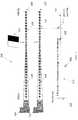
- FIG. 1illustrates one embodiment of an imaging system 100 .
- FIG. 2Aillustrates one embodiment of a picture of a three dimensional scene.
- FIG. 2Billustrates one embodiment of another picture of the three dimensional scene.
- FIG. 3illustrates blur differences of objects in the two pictures.
- FIG. 4illustrates modeling the blur difference between an object in the two pictures.
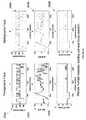
- FIG. 5A(prior art) is a graph of the auto-focus hill-climbing algorithm.
- FIG. 5Bis a graph illustrating one embodiment of fast auto-focus algorithm.
- FIG. 6is a flow diagram of a method for performing fast auto-focus.
- FIG. 7is a diagram illustrating one embodiment of focusing on a test image for a picture number representing the focused image.
- FIG. 8is a diagram illustrating one embodiment of a blur difference between two pictures of the test image.
- FIG. 9is a diagram illustrating a calculated blur difference between the two pictures.
- FIG. 10is a diagram illustrating one embodiment of focusing on a test image for a picture number that is out of focus.
- FIG. 11is a diagram illustrating one embodiment of a blur difference between two pictures of the test image.
- FIG. 12is a diagram illustrating a calculated blur difference between the two pictures as compared to the calculated blur difference in FIG. 9 .
- FIG. 13is a diagram illustrating one embodiment of focusing on a test image for a picture number that is out of focus.
- FIG. 14is a diagram illustrating one embodiment of a blur difference between two pictures of the test image.
- FIG. 15is a diagram illustrating a calculated blur difference between the two pictures as compared to the calculated blur difference in FIGS. 9 and 12 .
- FIG. 16is a graph illustrating a plot of the blur differences versus reference picture number.
- FIGS. 17A-Bare graphs illustrating shifting plots of blur differences versus reference picture number.
- FIG. 18is a diagram illustrating one embodiment of a set of blur difference reference curves.
- FIG. 19A-Dare graphs of one embodiment of method 600 illustrated in FIG. 6 .
- FIGS. 20-22is one embodiment of a set of images illustrating the convergence of the fast auto-focus at the mask location shown.
- FIG. 23illustrates a set of masks used to converge the fast auto focus results as illustrated in FIGS. 24-30 .
- FIGS. 24-30are graphs illustrating fast auto-focus convergence results for the different image masks of FIG. 23 .
- FIG. 31is a diagram illustrating one embodiment of an image device control unit that includes an auto-focus unit.
- FIG. 32Ais a diagram of one embodiment of an operating environment suitable for practicing the present invention.
- FIG. 32Ba diagram of one embodiment of a computer system suitable for use in the operating environment of FIG. 322A .
- FIG. 33is a block diagram illustrating one embodiment of an imaging system that computes the blur difference between two pictures of a test image using two sensors at different focusing distances from the test subject.
- a traditional auto-focus schemesearches for the peak of the auto-focus curve (e.g., peak-hold-integrate method, hill-climbing, etc.).
- the auto-focus information contained in the curveis a qualitative measure of image defocus, or blurring, and an auto-focus scheme attempts to minimize image blurring.
- an auto-focus schememeasures qualitative blurring and blurring is related to depth
- the auto-focus curvecontains depth information. This is because the peak of the curve corresponds to the in-focus position. For example, consider the case where the scene consists of a single object on a constant background. If the depth of the object is also known, the camera could predict a focus position at which the object is in focus. As described below with reference to FIG. 3 , because blur differences are related to depth, blur differences can be used in an auto-focus scheme to determine the picture that is in-focus, or equivalently, the focus position for the three dimensional scene.
- FIG. 1illustrates one embodiment of camera 100 .
- camera 100comprises lens 102 , sensor 104 , control unit 106 , storage 108 , and lens opening 110 .
- Camera 100may be digital or film still camera, video camera, surveillance camera, robotic vision sensor, image sensor, etc.
- Sensor 104captures an image of a scene through lens 102 .
- camera 100comprises one sensor.
- camera 100can have multiple sensors at different focusing distance from test subject.
- Sensor 104can acquire a still picture, such as in a digital or film still camera, or acquire a continuous picture, such as a video or surveillance camera. In addition, sensor 104 can acquire the image based on different color models used in the art, such as Red-Green-Blue (RGB), Cyan, Magenta, Yellow, Green (CMYG), etc.
- Control unit 106typically manages the sensor 104 automatically and/or by operator input. Control unit 106 configures operating parameters of the sensor 104 and lens 102 such as, but not limited to, the lens focal length, f, the aperture of the lens, A, lens focus position, and (in still cameras) the lens shutter speed.
- control unit 106may incorporate an auto-focus unit 120 (shown in phantom) that controls the automatic focusing of lens 102 on the scene. Embodiments of this invention are incorporated into auto-focus unit 120 .
- the image(s) acquired by sensor 104are stored in the image storage 108 .
- FIG. 2Aillustrates one embodiment of a picture of a three dimensional scene.
- camera 202prepares to take a picture by focusing on three-dimensional scene 200 .
- camera 202is camera 100 as illustrated in FIG. 1 .
- Three-dimensional scene 200comprises car 204 , person 206 , mountain backdrop 208 , and sun 210 .
- Each of the objects in three-dimensional scene 200is at different distances from camera 202 . For example, based on distance scale 224 , car 204 is closest to camera 202 , followed in order by person 206 , mountain backdrop 208 , and sun 210 .
- Picture 214illustrates this result.
- car 216is in focus and not blurry.
- Blurriness in picture 214is represented with a thicker border for each object in the picture.
- car 216has a relatively thin border.
- Person 218has a thicker border.
- Mountain backdrop 220has a thicker border 226 and sun 222 has the thickest border, 228 .
- sun 222is blurrier than mountain backdrop 220 , which is blurrier than person 218 , which in turn is blurrier than car 216 .
- FIG. 2Billustrates one embodiment of another picture 254 of the three dimensional scene 200 with a different focus position of camera 202 .
- camera 202 focus position 252is before car 204 , specifically, greater than or equal to 1 DOF (depth of field) from distance 222 .
- the image of car 204 in picture 254is blurrier than in the picture 214 .
- picture 254comprises person 258 , mountain backdrop 260 , and sun 262 .
- car 256is blurry with a slightly thicker border as compared with the focused car 216 in picture 214 .
- FIG. 3illustrates the absolute blur for different objects in FIGS. 2A and 28 using pillboxes of different shapes.
- the blur difference between car 216 in picture 214 and car 256 in picture 254can be seen by examining the difference heights and widths of the two pillboxes shown in 302 A-B. This blur difference results because two different focus positions were used to capture the pictures of FIGS. 2A and 2B .
- a pillboxis mathematical mask used to represent the blurring of an object in an image.
- a pillboxis a blur convolution consisting of equal valued pixels in a circular area centered on a reference pixel.
- a tall thin pillboxrepresents an object that has undergone less blurring versus a shorter, squatter pillbox.
- pillbox 302 Ais taller and thinner than pillbox 302 B. Because pillbox 302 A is taller than pillbox 302 B, there is a blur difference between the two pillboxes, represented by delta blur 310 . Delta blur 310 is used for fast auto focus, and to obtain distance information for the object.
- FIG. 3also illustrates blur differences for the other objects in picture 214 and picture 254 .
- the blur difference 312(labeled “delta blur 2 ”) is the difference between blurs 304 A-B for person 218 in picture 214 and person 258 in picture 254 , respectively.
- Blur difference 314(labeled “delta blur 3 ”) is the difference between blurs 306 A-B for mountain backdrop 220 in picture 214 and mountain backdrop 260 in picture 254 , respectively.
- Blur difference 316(labeled “delta blur 4 ”) is the difference between blurs 308 A-B for sun 222 in picture 214 and sun 262 in picture 254 , respectively.
- FIG. 4illustrates the modeling and the computation of the blur difference 312 between an object in the two pictures in FIGS. 2A and 2B .
- blur difference 312(labeled “delta blur 2 ”) is computed by applying a 3 ⁇ 3 matrix 402 between blur models 404 A-B.
- Blur models 404 A-Bcan be Gaussian functions, pillbox functions, or other blur models known in the art.
- blur models 404 A-Bare Gaussian functions and 3 ⁇ 3 matrix 402 is a blurring matrix that blurs blur model 404 A into 404 B.
- 3 ⁇ 3 matrix 402can be applied to blur model 404 A once or many times depending on the amount blurring needed to convolve blur model 404 A into blur model 404 B.
- 3 ⁇ 3 matrix 402represents blurring of one blur unit.
- 3 ⁇ 3 matrix 402is also referred to as a blur kernel.
- the blur kernelis of dimension n ⁇ n, where n is an integer.
- the blur kernelis applied via convolution repeatedly on the sharper image until a new image is produced that closely matches the more blurred image. Qualitatively, this is illustrated by the smooth, black curve on blur model 404 B. This black curve closely approximates the pillbox 304 B after the blur kernel has been applied m times. The number of times the blur kernel has been applied is also called the iterations number.
- FIG. 5Ais a graph of the auto-focus hill-climbing algorithm. This algorithm finds the peak of auto-focus curve by calculating gradient information in the given scene. However, this algorithm can require up to forty or greater pictures in order to converge on a focused image.
- curve 504represents the auto-focus curve for a location in a scene.
- Point 502represents the picture number corresponding to the in focus position of curve 504 .
- the in focus positionis identified by the peak of curve 504 .
- Different points 500 on curve 504are different picture numbers for a given camera setting. In one embodiment, a picture number is a measure of the focus distance, or focus position, of the lens on camera 100 .
- Picture numberscan be a numbered sequence representing different focus distances.
- a sequence of picture numbers for a particular lens combinationcan be focusing distance of 35, 40, 60, 70, 80, 100, 125, 150, 200, 300, 500, 1000 centimeters and infinity.
- each picture numberrepresents a fixed depth of field difference from an adjacent picture number.
- picture number n ⁇ 1, n, n+1can be separated by 1 ⁇ 2, 1, 2, etc. depth of fields.
- each picture numberalso represents a fixed depth of focus difference.
- the hill-climbing algorithmworks by recording images at different pictures numbers to compute auto-focus information.
- the objective of these algorithmsis to find the maximum gradient value corresponding to a given location in the scene.
- the algorithmperforms a search until the picture number corresponding to point 502 is found. While this algorithm eventually determines the optimal point 502 on the curve, this algorithm tends to go back and forth around point 502 . This results in a large number of pictures for convergence.
- FIG. 5Bis a graph illustrating one embodiment of fast auto-focus.
- the fast auto-focuspredicts a new picture number on auto-focus curve 504 using blur difference information from other images.
- a cameracalculates the blur difference between two images. Using the blur difference, the camera moves the current focus position to a new focus position. Two additional pictures are then captured. The process repeats, until the computed change in blur is less than a preset threshold.
- the iteration numberis the number of times the blur kernel is applied to the sharper of the two captured images via convolution, in order to produce an image that has a blur equivalent to the second, more blurred, captured image.
- the lensmoves to the new and final focus position and the final picture is captured.
- the bluris spatially varying in the image, attention is restricted to a specific scene location in the image.
- FIG. 6is a flow diagram of a method 600 for performing fast auto-focus.
- auto-focus unit 120executes method 600 to assist in auto-focusing camera lens 102 on the scene.
- method 600determines a starting reference picture.
- Method 600can select a reference picture number at infinite focus, a picture number at the lens minimum focus distance, or a picture number somewhere in between.
- method 600captures two pictures. If the reference picture number is n, the first picture is captured at n and the second picture is captured at n+shift, where shift is an integer value. As stated previously, picture number n and n+shift can be separated by 1 ⁇ 2, 1, 2, etc. depth of fields. Analogously, each picture number pair also represents a fixed depth of focus difference.
- method 600computes the blur difference between the pictures captured at n (the reference picture number) and n+shift (the second captured picture).
- method 600calculates the blur difference between the two images by convolving one image into another image using a convolving blur kernel.
- method 600applies a blur kernel one or multiple times to determine the blur difference between to the whole or parts of two images.
- method 600applies a blur kernel to part of one image by using a mask.
- a maskrestricts the evaluation and/or processing of an image to part of the image defined by the mask. Masks are further described with reference to FIGS. 20-23 below.
- method 600can compute the blur difference using full or reduced resolution images.
- method 600determines the blur difference in the number of iterations needed to convolve one image to another using a 3 ⁇ 3 matrix (blur kernel) that represents one blur unit.
- the blur kernelcan be n ⁇ n.
- method 600compares the computed blur difference values and selects the ideal value. This is described in the patent “REDUCED HARDWARE IMPLEMENTATION FOR A TWO-PICTURE DEPTH MAP ALGORITHM”, application Ser. No. 12/111,548.
- the appropriate blur difference reference curveis selected from a set of blur difference reference curves.
- the set of curveswill be identical. That is, each curve will be a shifted version of a reference curve. In another embodiment, a set of curves with different characteristics will exist.
- the appropriate blur difference reference curveis determined by finding the curve whose zero crossing location is closest to the current reference picture number n. The generation of such a set of blur difference reference curves is given in FIGS. 7-17 . One embodiment that uses the computed blur difference is further described with reference to FIGS. 19-22 below.
- method 600computes the new reference picture number.
- the appropriate blur difference reference curveneeds to be selected from a set of blur difference reference curves.
- the computed blur difference quantityis applied to the vertical axis of the selected curve to determine the new picture number located on the horizontal axis.
- method 600instructs the camera to move the lens to a new reference picture number ni.
- the new picture numberresults from blocks 604 to 607 .
- method 600determines if the blur difference/iterations number is less than a pre-determined threshold. In one embodiment, method 600 uses the absolute value of the blur difference/iterations quantity. If so, the image is focused and method 600 instructs the camera to capture the final picture at picture number location ni using block 612 .
- method 600instructs the camera to capture two pictures at block 614 .
- the first pictureis captured at picture number ni while the second picture is captured at picture number ni+shift. Execution proceeds to block 604 above.
- FIGS. 7-15illustrate one embodiment of the results of method 600 for computing different blur differences at different picture numbers.
- FIGS. 7-9are diagrams illustrating the blur difference between two blurred step edge images.
- FIG. 7is a diagram illustrating one embodiment of focusing on a test subject 710 for a picture number representing the focused image.
- camera 702focuses on test subject 710 .
- Camera 702can focus on test subject 710 at one of the many different picture numbers 704 along a distance 706 .
- camera 702can focus on test subject 710 at the minimal picture number 712 at 35 cm (or closer) or at the picture number at infinity 714 .
- the optimally focused imageis at picture number 708 .
- the minimal picture numberdepends on the type of lens 102 camera 100 uses.
- FIG. 8is a diagram 800 illustrating one embodiment of a blur difference between two pictures of the test image.
- camera 802focuses on test subject 710 at picture number 808 .
- camera 802can focus on test subject 710 at a different picture numbers 804 along a distance 806 .
- diagram 700 of camera 702 focusing on test image 710 at picture number 708is superimposed on FIG. 8 .
- FIG. 9is a diagram 900 of one embodiment illustrating a calculated blur difference between two images taken at picture numbers 708 and 808 .
- graph 902illustrates the blur difference between images taken at picture number 708 and picture number at 808 .
- Point 908 on graph 902represents this blur difference and is plotted on graph 902 as the number of iterations used to convolve the image at picture number 808 to the image at picture number 708 .
- point 908is close to zero iterations.
- Images at picture numbers close to or at the optimal focusing locationhave smaller blur differences than those for images at adjacent picture numbers for identical shift values.
- small blur differencescorrespond to small iteration numbers because fewer numbers of blur iterations is needed to convolve one image into another.
- the amount of blurcan be measured in the number of iterations used to convolve one image into another.
- images far from the optimal focusingcan have large blur differences with large numbers of iterations.
- FIGS. 10-12are diagrams illustrating the blur difference between two blurred step edge images and comparing this blur difference with the one calculated in FIG. 9 .
- FIG. 10is a diagram 1000 illustrating one embodiment of the focusing on test subject 1010 for a picture number that is out of focus.
- camera 1002focuses on test subject 1010 at picture number 1008 .
- picture number 1008is closer to camera 1002 than the optimally focused picture at picture number 1012 .
- the image at picture number 1008is out of focus and blurred as compared with the image at picture number 708 in FIG. 7 .
- FIG. 11is a diagram illustrating one embodiment of a blur difference between two pictures of the test subject 1010 .
- camera 1102focuses on test subject 1010 at picture number 1108 .
- camera 1102can focus on test subject 1010 at different picture numbers 1104 along a distance 1106 .
- diagram 1000 of camera 1002 focusing on test image 1010 at picture number 1008is superimposed on FIG. 11 .
- FIG. 12is a diagram illustrating a calculated blur difference between the two pictures as compared to the calculated blur difference in FIG. 9 .
- graph 1202illustrates the blur difference between images taken at picture numbers 1008 and 1108 .
- Point 1210 on graph 1202represents this blur difference and is plotted on graph 1202 as the number of iterations to convolve image at picture number 1108 to the image at picture number 1008 .
- the blur difference calculated in FIG. 9is at point 1208 .
- Point 1210represents a larger number of iterations as compared with point 1208 .
- Point 1210is negative because the picture captured at picture number 1008 is more blurred than the picture captured at picture number 1108 .
- FIGS. 10 and 11are superimposed on FIG. 12 .
- FIGS. 13-15are diagrams illustrating the blur difference between two blurred step edge images and comparing this blur difference with the one calculated in FIGS. 9 and 12 .
- FIG. 13is a diagram 1300 illustrating one embodiment of the focusing on test subject 1310 for a picture number that is out of focus.
- camera 1302focuses on test subject 1310 at picture number 1308 .
- picture number 1308is further from camera 1302 than the optimally focused picture at picture number 1312 .
- the image at picture number 1308is out of focus and blurred as compared with the image at picture number 708 in FIG. 7 .
- FIG. 14is a diagram illustrating one embodiment of a blur difference between two pictures of the test subject 1310 .
- camera 1402focuses on test subject 1310 at picture number 1408 .
- camera 1402can focus on test subject 1310 at different picture numbers 1404 along a distance 1406 .
- diagram 1300 of camera 1302 focusing on test subject 1310 at picture number 1308is superimposed on FIG. 14 .
- FIG. 15is a diagram illustrating a calculated blur difference between the two pictures as compared to the calculated blur difference in FIGS. 9 and 12 .
- graph 1502illustrates the blur difference between images taken at picture numbers 708 and 808 , 1008 and 1108 and 1308 and 1408 .
- Point 1512 on graph 1502represents the latter blur difference and is plotted on graph 1502 as the number of iterations to convolve image at picture number 1308 to the image, at picture number 1408 .
- the blur difference calculated in FIGS. 9 and 12are at points 1508 and 1510 , respectively.
- Point 1512represents a larger number of iterations as compared with point 1508 .
- point 1512is positive because the picture captured at picture number 1308 is less blurred than the picture captured at picture number 1408 .
- the block diagrams of FIGS. 13 and 14are superimposed on FIG. 15 .
- FIG. 16is a graph 1602 illustrating a plot of the blur iterations versus reference picture number.
- points 1508 , 1510 and 1512represent the calculated blur differences in FIGS. 9 , 12 , and 15 along iterations axis 1604 and picture number axis 1606 .
- Curve 1608can be drawn through points 1508 , 1510 , and 1512 . As illustrated in FIG. 16 , curve 1608 is nearly linear in between points 1508 , 1510 , and 1512 . Furthermore, curve 1608 transitions from negative to positive at point 1610 .
- Zero iterationdenotes the focused point for test subject 1310 . In one embodiment, a zero iterations value can result if the two captured pictures have the same amount of blur.
- the iteration numberwill change from negative to positive for each successive two picture capture.
- the picture number associated with this negative to positive transitionclosely approximates the focused point.
- blur differencecan be used to predict where an image is focused by developing curve 1608 for an image and predicting which picture number has zero iterations on curve 1608 , or, in the typical case, which picture number is associated with the negative to positive transition in iterations value.
- the use of this curve for predictioncan be employed in method 600 in FIG. 6 by auto-focus unit 120 above.
- a blur difference curvesuch as curve 1608 in FIG. 16
- the blur differencecan be modeled using polynomial, interpolation, or other algorithms known in the art to approximate a curve.
- a curvecan be constructed from computed blur differences to predict an optimal focus distance.
- FIGS. 17A-Bare graphs illustrating shifting plots of blur iterations versus reference picture number.
- curves 1702 and 1752are blur difference curves for test subject 1706 and 1756 at different picture numbers.
- curve 1702transitions from negative to positive at point 1704 while curve 1752 transitions from negative to positive at point 1754 .
- different blur difference curvescan result when test subject 1706 / 1756 changes.
- an auto-focus algorithmuses different blur difference reference curves for focusing and to determine a focus distance.
- FIG. 18is a block diagram illustrating one embodiment of a set of empirical blur difference reference curves.
- camera 1802stores several blur difference curves 1810 .
- each picture numberrepresents a different focus distance.
- Each curveis plotted as the number of iterations versus reference picture number. Note that each curve goes from negative iterations to positive number of iterations. Thus, each curve has a picture number where there are zero iterations. This point defines the focused image for that focus distance.
- blur difference reference curve 1816represents that blur difference curve for a focus distance 1806 of 40 cm.
- blur difference reference curve 1814represents a focus distance 1808 of 1000 cm.
- the different reference curvesare generated using a number of test targets.
- Each cameracan have different number of reference curves for different camera configurations (e.g., the camera's lens configuration, and other parameters (focal length, aperture, etc)). For example, one camera at maximum focal length would have four reference curves. At minimum focal length, this camera would have eleven reference curves. Different cameras could have different numbers of reference curves.
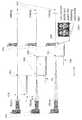
- FIG. 19 A-Dare graphs representing different blur difference curves used to predict reference picture numbers as described in FIG. 6 , at block 606 .
- FIG. 19Ais a graph one embodiment of illustrating the predicting of a next reference picture number using a pair of images.
- camera 1902acquires two images 1916 A-B at and near distance 1908 (previously defined as n and n+shift) of subject 1904 measured on distance 1906 . Because distance 1908 is too close to the camera 1902 as compared with subject 1904 , images 1916 A-B are blurry. Based on distance 1908 , camera 1902 uses the blur difference reference curve 1912 to predict the next picture number for the auto-focus search.
- the computed blur difference between images 1916 A-Bcorresponds to the iterations number shown at point 1914 . As a result, the lens focus position is moved from distance 1908 to distance 1932 , FIG. 19B .
- FIG. 19Bis a graph illustrating one embodiment of the selection of the next reference picture number based on two images acquired at and near distance 1932 .
- camera 1902selects blur difference curve 1926 to predict the next picture number.
- the computed blur difference between images 1930 A-Bcorrespond to the iterations number shown at point 1928 .
- the lens focus positionis moved from distance 1932 to distance 1944 , in FIG. 19C .
- the graph from FIG. 19Ais superimposed on FIG. 19B .
- FIG. 19Cis a graph illustrating one embodiment of the selection of the next reference picture number based on two images acquired at and near distance 1944 .
- camera 1902acquires images 1950 A-B at and near distance 1944 (defined as n 2 and n 2 +shift). Images 1950 A-B are less blurry that images 1930 A-B, but have not converged on an in-focus picture.
- Camera 1902selects a new picture number based on curve 1946 .
- the computed blur difference between images 1950 A-Bcorrespond to the iterations number shown at point 1948 . Since the iterations number is smaller than a pre-defined threshold, the lens focus position is moved from distance 1944 to the final distance 1964 , in FIG. 19D .
- the graphs from FIG. 19A-Bare superimposed on FIG. 19C .
- FIG. 19Dis a graph illustrating the convergence of the auto-focus search.
- camera 1902acquires image 1966 at distance 1964 .
- image 1966represents the in-focus image of test subject 1904 that was achieved by acquiring three pairs of image using method 600 .
- graphs from FIG. 19A-Care superimposed on FIG. 19D .
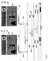
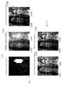
- FIGS. 20-22illustrates different examples of a camera using fast auto-focus to converge on a test subject with different image masks.
- FIGS. 20-22are described in reference to camera 100 in FIG. 1 above.
- FIG. 20is one embodiment of a set of images illustrating the convergence of the fast auto-focus search using mask 2002 .
- mask 2002is used to converge on a focused image.
- Mask 2002restricts the evaluation area to a subset of the image, such as to one of the faces of the models in the image.
- mask 2004restricts comparison of blur differences to image area 2004 of mask 2002 .
- the masksdelineate areas in the image containing space invariant blur.
- the facial areasare identified and acquired using face detection technology known in the art. In general a mask of any size and shape can be applied to an arbitrary location in an image suspected of containing space invariant blur.
- Images 2010 A-Dillustrate one embodiment of a set of images acquired while converging on rear model 2008 A-D using mask 2002 .
- Mask 2002blocks off analysis of front model 2006 A-D) when determining blur difference using method 600 .
- Image 2010 Ais at the starting picture number, picture number 209 , and illustrates a blurred back model 2008 A with a less blurred front model 2006 A.
- Camera 100focuses lens 102 to picture number 133 and acquires image 2010 B.
- Image 2010 Bhas a more in-focus front model 2006 B and less in-focus back model 2008 B.
- Camera 100focuses lens 102 to a new focus position at picture number 112 and acquires image 2010 C.
- Image 2010 Chas front model 2006 C blurrier than back model 2008 C.
- Back model 2008 Cis close to being in-focus.
- Camera 100focuses lens 102 to in-focus position at picture number 110 and acquires image 2010 D.
- Image 2010 Drepresents an in-focus image for back model 2008 D.
- Front model 2006 Dis out of focus
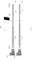
- FIG. 21is one embodiment of a set of images illustrating the convergence of the fast auto-focus search using mask 2102 .
- mask 2102is used to converge on a focused image.
- mask 2102restricts comparison of blur differences to image area 2104 of mask 2102 .
- Images 2110 A-Dillustrate one embodiment of a set of images acquired while converging on rear model 2108 A-D using mask 2102 .
- Mask 2102blocks off analysis of front model 2106 A-D when determining blur difference using for camera 100 using method 600 .
- Camera 100acquires image 2110 A at the starting picture number 225 and illustrates a more blurred hack model 2108 A with less blurred front model 2106 A.
- Camera 100focuses tens 102 at picture number 113 and acquires image 2110 B.
- Image 2110 Bhas a less blurred front model 2106 B and a more blurred back model 2108 B.
- Camera 100focuses lens 102 at picture number 93 and acquires image 2110 C.
- Image 2110 Chas front model 2106 C less blurred than hack model 2108 C.
- Back model 2108is close to being in focus.
- Camera 100focuses lens 102 to in-focus position at picture number 92 and acquires image 2110 D.
- Image 2110 Drepresents an in-focus image for back model 2108 D.
- Front model 2106 Dis out of focus.
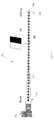
- FIG. 22is one embodiment of a set of images illustrating the convergence of the fast auto-focus search using mask 2202 .
- mask 2202is used to converge on a focused image.
- mask 2202restricts comparison of blur differences to image area 2204 of mask 2202 .
- Images 2210 A-Cillustrate one embodiment of a set of images acquired while converging on front model 2208 A-C using mask 2202 .
- Mask 2202blocks off analysis of rear model 2206 A-C when determining blur difference using for a camera using method 600 .
- Camera 100acquires image 2210 A at the starting picture number 68 .
- Image 2210 Aillustrates a blurred front model 2208 A with a less blurred back model 2206 A.
- Camera 100focuses lens 102 at picture number 86 and acquires image 2210 B.
- Image 2210 Bhas an in focus front model 2206 B and less in-focus back model 2208 B.
- Image 2210 Crepresents an in-focus image for front model 2206 C.
- Back model 2206 Cis out of focus.
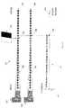
- FIG. 23is a set of masks used in conjunction with fast auto-focus results in FIGS. 24-30 .
- image masks 2302 A-Gare used to restrict the evaluation and processing area of an image to the white area of the mask.
- camera 100uses image masks 2302 A-G to evaluate and/or process different parts of an image.
- mask 2302 Arestricts the processing to the eyes and nose of the white model.
- Mask 23021 Brestricts the processing to the eyes and nose of the black model.
- Mask 2302 Crestricts the processing to the eyes and nose of the white model as in mask 2302 A.
- the distance of the white model corresponding to mask 2302 Ais closer than the distance of the white model corresponding to mask 2302 C.
- Mask 2302 Drestricts the processing to the faces of the front and back models, where the area for the front model is greater than the area of the back model.
- Mask 2302 Eis similar to the mask 2302 D by restricting the processing area to the faces of the front and back models, with the area for the front model is greater than the area of the back model.
- Mask 2302 Fhas a mask area that includes both the front and back models, where the area for the front model is greater than the area of the back model. Both encompass a smaller area than those in 2302 E.
- Mask 2302 Ghas a mask area that includes both the front and back models, with roughly equal sizes for each model and encompassing a smaller area than mask 2302 E or 2302 F.
- FIGS. 24-30are graphs illustrating fast auto-focus convergence results for the different image masks of FIG. 23 .
- three sets of graphsillustrate the fast auto-focus using mask 2302 A.
- the graphsare in-focus graphs 2402 A-B that illustrate the focused pictured number based on the starting picture number, final shift graph 2404 A-B that illustrate the shift that occurs right before the lens is moved to the in focus position, and number of two pictures graphs 2406 A-B that illustrates the number of two picture pairs used to converge on the focused picture.
- graphs 2402 A, 2404 A, and 2406 Aresult from camera 100 focusing on the foreground nose of mask 2302 A.
- Graph 2402 Aillustrates that the focused picture number varies with the starting point of the fast auto-focus. For example, the focused picture number varies from 149 to 158 depending on the starting picture number.
- Graph 2404 Areflects the shift that occurs right before the lens is moved to the in focus position. It is interesting to note that the fast auto-focus converges using 1-5 two picture pairs as illustrated in graph 2406 A.
- graphs 2402 B, 2404 B, and 2406 Bresult from camera 100 focusing on the background eyes of mask 2302 A.
- Graph 2402 Billustrates that the focused picture number varies with the starting point of the fast auto-focus, but the variance is less than in graph 2402 A. For example, the focused picture number varies from 146 to 149 depending on the starting picture number.
- Graph 2404 Bthe shift that occurs right before the lens is moved to the in focus position. It is interesting to note that the fast auto-focus converges using 1-3 two picture pairs as illustrated in graph 2406 B.
- FIG. 25illustrates in-focus picture graphs 2502 A-B, final shift graphs 2504 A-B, and number of two pictures needed graphs 2506 A-B for the foreground nose and background eyes of mask 2302 B.
- graphs 2502 A-Billustrate that the in focus picture varies between 156-159 and 151-153, respectively for the foreground nose and background eyes.
- Final shift graphs 2504 A-Billustrate the shift that occurs right before the lens is moved to the in focus position, respectively for the foreground nose and background eyes of mask 2302 B.
- the number of two picture pairs neededvaries from 1-4 for the foreground nose and background eyes of mask 2302 B.
- FIG. 26illustrates in-focus picture graphs 2602 A-B, final shift graphs 2604 A-B, and number of two pictures needed graphs 2606 A-B for the foreground nose and background eyes of mask 2302 C.
- graphs 2602 A-Billustrate that the in focus picture varies between 155-159 and 151-154, respectively for the foreground nose and background eyes.
- Final shift graphs 2604 A-Billustrate the shift that occurs right before the lens is moved to the in focus position, respectively for the foreground nose and background eyes of mask 2302 C.
- the number of two picture pairs neededvaries from 1-5 for the foreground nose and background eyes of mask 2302 C.
- FIG. 27illustrates in-focus picture graphs 2702 A-B, final shift graphs 2704 A-B, and number of two pictures needed graphs 2706 A-B for the foreground and background faces of mask 2302 D.
- graphs 2702 A-Billustrate that the in focus picture varies between 136-137 and 117-119, respectively for the foreground and background faces.
- Final shift graphs 2704 A-Billustrate the shift that occurs right before the lens is moved to the in focus position, respectively for the foreground and background faces of mask 2302 D.
- the number of two picture pairs neededvaries from 1-3 for the foreground nose and background eyes of mask 2302 D.
- FIG. 28illustrates in-focus picture graphs 2802 A-B, final shift graphs 2804 A- 13 , and number of two pictures needed graphs 2806 A-B for the foreground and background faces of mask 2302 E.
- graphs 2802 A-Billustrate that the in focus picture varies between 128-131 and 108-111, respectively for the foreground and background faces.
- Final shift graphs 2804 A-Billustrate the shift that occurs right before the lens is moved to the in focus position, respectively for the foreground and background faces of mask 2302 E.
- the number of two picture pairs neededvaries from 1-3 for the foreground nose and background eyes of mask 2302 E.
- FIG. 29illustrates in-focus picture graphs 2902 A-B, final shift graphs 2904 A-B, and number of two pictures needed graphs 2906 A-B for the foreground and background faces of mask 2302 F.
- graphs 2902 A-Billustrate that the in focus picture varies between 98-100 and 90-93, respectively for the foreground and background faces.
- Final shift graphs 2904 A-Billustrate the shift that occurs right before the lens is moved to the in focus position, respectively for the foreground and background faces of mask 2302 F.
- the number of two picture pairs neededvaries from 1-3 for the foreground nose and background eyes of mask 2302 F.
- FIG. 30illustrates in-focus picture graphs 3002 A-B, final shift graphs 3004 A-B, and number of two pictures needed graphs 3006 A-B for the foreground and background faces of mask 2302 G.
- graphs 3002 A-Billustrate that the in focus picture varies between 85-87 and 81-82, respectively for the foreground and background faces.
- Final shift graphs 3004 A-Billustrate the shift that occurs right before the lens is moved to the in focus position, respectively for the foreground and background faces of mask 2302 G.
- the number of two picture pairs neededvaries from 1-3 for the foreground nose and background eyes of mask 2302 G.
- FIG. 31is a block diagram illustrating one embodiment of an image device control unit that computes parameters used to auto-focus a lens, such as lens 102 in camera 100 described in FIG. 1 .
- image control unit 106contains auto-focus unit 120 .
- image control unit 106does not contain auto-focus unit 120 , but is coupled to auto-focus unit 120 .
- Auto-focus unit 120comprises blur difference curve module 3102 , blur difference module 3104 , blur comparison module 3106 , and picture number prediction module 3108 .
- Blur difference curve module 3102selects blur difference reference curve as described in FIG. 6 , at block 606 .
- Blur difference module 3104computes the blur difference as described in FIG. 6 , at block 604 and FIG. 4 .
- Blur comparison modulecompares the blur difference between two pictures as described in FIG. 6 , block 605 .
- Picture number prediction module 3108predicts the next picture number as described with reference to FIG. 6 , block 607 .
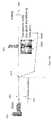
- FIG. 33is a diagram illustrating one embodiment of an imaging system 3304 that computes the blur difference between two pictures of a test image using two sensors 3306 AB at different focusing distances from the test subject.
- imaging system 3304comprises lens 3308 , splitter 3310 , and sensors 3306 AB.
- Sensors 3306 ABare at distances 3302 AB from lens 3308 , respectively. Because sensors 3306 AB have different focusing distances, each sensor acquires a picture with different focal properties.
- imaging system 3304can acquire images at adjacent pictures number as described with reference to FIG. 8 , above. Therefore, imaging system can utilize method 600 as described in FIG. 6 above to auto-focus imaging system 3304 with sensors 3306 AB.
- a server computer 3201is coupled to, and provides data through, the Internet 3205 .
- a client computer 3203is coupled to the Internet 3205 through an ISP (Internet Service Provider) 3205 and executes a conventional Internet browsing application to exchange data with the server 3201 .
- ISPInternet Service Provider
- client 3203 and/or server 3205can control the auto-focusing of a coupled camera and/or lens using the fast auto-focus method described in FIG. 6 or 18 .
- the server 3201can be part of an ISP which provides access to the Internet for client systems.
- Internetrefers to a network of networks which uses certain protocols, such as the TCP/IP protocol, and possibly other protocols such as the hypertext transfer protocol (HTTP) for hypertext markup language (HTML) documents that make up the World Wide Web (web).
- HTTPhypertext transfer protocol
- HTMLhypertext markup language
- the physical connections of the Internet and the protocols and communication procedures of the Internetare well known to those of skill in the art.
- Access to the Internetallows users of client computer systems to exchange information, receive and send e-mails, view documents, such as documents which have been prepared in the HTML format, and receive content. It is readily apparent that the present invention is not limited to Internet access and Internet web-based sites; directly coupled and private networks are also contemplated.
- FIG. 32BOne embodiment of a computer system suitable for use as server 3201 is illustrated in FIG. 32B .
- the computer system 3210includes a processor 3220 , memory 3225 and input/output capability 3230 coupled to a system bus 3235 .
- the memory 3225is configured to store instructions which, when executed by the processor 3220 , perform the methods described herein.
- the memory 3225may also store data for a fast auto-focus mechanism.
- Input/output 3230provides for the delivery and display of the data for a fast auto-focus mechanism or portions or representations thereof, and also the input of data of various types for storage, processing or display.
- Input/output 3230also encompasses various types of computer-readable media, including any type of storage device that is accessible by the processor 3220 .
- server 3201is controlled by operating system software executing in memory 3225 .
- Input/output 3230 and related mediastore the machine-executable instructions for the operating system and methods of the present invention as well as the data for a fast auto-focus mechanism.
- FIGS. 32A-BThe description of FIGS. 32A-B is intended to provide an overview of computer hardware and other operating components suitable for implementing the invention, but is not intended to limit the applicable environments.
- the computer system 3240is one example of many possible computer systems which have different architectures.
- a typical computer systemwill usually include at least a processor, memory, and a bus coupling the memory to the processor.
- One of skill in the artwill immediately appreciate that the invention can be practiced with other computer system configurations, including multiprocessor systems, minicomputers, mainframe computers, and the like.
- the inventioncan also be practiced in distributed computing environments where tasks are performed by remote processing devices that are linked through a communications network.
Landscapes
- Engineering & Computer Science (AREA)
- Multimedia (AREA)
- Signal Processing (AREA)
- Studio Devices (AREA)
- Image Processing (AREA)
- Automatic Focus Adjustment (AREA)
Abstract
Description
Depthcar=f(fl,Fnumber,D1,D2,Δblurcar)
Depthperson=f(fl,Fnumber,D1,D2,Δblurperson)
Depthmountain=f(fl,Fnumber, D1,D2,Δblurmountain)
Depthsun=f(fl,Fnumber,D1,D2,Δblursun) (1)
where f is the function that relates blur difference to depth, fl is the focal length of the lens, Fnumberis the f-number of the lens, D1 and D2 are the distances between the lens and the image sensor for two different focus positions, and Δblur is the computed blur difference for a specific picture location. As stated previously, the blur difference results from capturing two pictures using two different focus positions.
Claims (13)
Priority Applications (3)
| Application Number | Priority Date | Filing Date | Title |
|---|---|---|---|
| US12/242,805US8194995B2 (en) | 2008-09-30 | 2008-09-30 | Fast camera auto-focus |
| BRPI0902791-2ABRPI0902791B1 (en) | 2008-09-30 | 2009-08-28 | COMPUTER METHOD, MEDIA-READY BY MACHINE, APPARATUS, AND SYSTEM |
| CN2009101745538ACN101713902B (en) | 2008-09-30 | 2009-09-28 | Fast camera auto-focus |
Applications Claiming Priority (1)
| Application Number | Priority Date | Filing Date | Title |
|---|---|---|---|
| US12/242,805US8194995B2 (en) | 2008-09-30 | 2008-09-30 | Fast camera auto-focus |
Publications (2)
| Publication Number | Publication Date |
|---|---|
| US20100080482A1 US20100080482A1 (en) | 2010-04-01 |
| US8194995B2true US8194995B2 (en) | 2012-06-05 |
Family
ID=42057568
Family Applications (1)
| Application Number | Title | Priority Date | Filing Date |
|---|---|---|---|
| US12/242,805Expired - Fee RelatedUS8194995B2 (en) | 2008-09-30 | 2008-09-30 | Fast camera auto-focus |
Country Status (3)
| Country | Link |
|---|---|
| US (1) | US8194995B2 (en) |
| CN (1) | CN101713902B (en) |
| BR (1) | BRPI0902791B1 (en) |
Cited By (14)
| Publication number | Priority date | Publication date | Assignee | Title |
|---|---|---|---|---|
| US20100079608A1 (en)* | 2008-09-30 | 2010-04-01 | Earl Quong Wong | Method And Apparatus For Super-Resolution Imaging Using Digital Imaging Devices |
| US20110229052A1 (en)* | 2010-03-22 | 2011-09-22 | Sony Corporation | Blur function modeling for depth of field rendering |
| US20110304696A1 (en)* | 2010-06-09 | 2011-12-15 | Thomson Licensing | Time-of-flight imager |
| US20130058581A1 (en)* | 2010-06-23 | 2013-03-07 | Beihang University | Microscopic Vision Measurement Method Based On Adaptive Positioning Of Camera Coordinate Frame |
| US20130063566A1 (en)* | 2011-09-14 | 2013-03-14 | Canon Kabushiki Kaisha | Determining a depth map from images of a scene |
| US20140063295A1 (en)* | 2012-03-15 | 2014-03-06 | Panasonic Corporation | Image processing apparatus, integrated circuit, program, imaging apparatus, and display apparatus |
| US20140313373A1 (en)* | 2013-04-19 | 2014-10-23 | Canon Kabushiki Kaisha | Imaging apparatus and its control method and program |
| US9030591B2 (en) | 2012-07-20 | 2015-05-12 | Apple Inc. | Determining an in-focus position of a lens |
| US20150279043A1 (en)* | 2014-03-28 | 2015-10-01 | Sony Corporation | Imaging system with depth estimation mechanism and method of operation thereof |
| US20150281553A1 (en)* | 2014-03-28 | 2015-10-01 | Panasonic Corporation | Image-capturing apparatus |
| US20160267670A1 (en)* | 2015-03-11 | 2016-09-15 | Sony Corporation | Image processing system with hybrid depth estimation and method of operation thereof |
| US9530214B2 (en) | 2014-12-04 | 2016-12-27 | Sony Corporation | Image processing system with depth map determination based on iteration count of blur difference and method of operation thereof |
| US10498976B2 (en) | 2014-12-05 | 2019-12-03 | Microsoft Technology Licensing, Llc | Virtual focus feedback |
| US10621729B2 (en) | 2016-06-12 | 2020-04-14 | Apple Inc. | Adaptive focus sweep techniques for foreground/background separation |
Families Citing this family (30)
| Publication number | Priority date | Publication date | Assignee | Title |
|---|---|---|---|---|
| US8280194B2 (en) | 2008-04-29 | 2012-10-02 | Sony Corporation | Reduced hardware implementation for a two-picture depth map algorithm |
| US8194995B2 (en) | 2008-09-30 | 2012-06-05 | Sony Corporation | Fast camera auto-focus |
| US8045046B1 (en)* | 2010-04-13 | 2011-10-25 | Sony Corporation | Four-dimensional polynomial model for depth estimation based on two-picture matching |
| JP2012003233A (en)* | 2010-05-17 | 2012-01-05 | Sony Corp | Image processing device, image processing method and program |
| EP2642245B1 (en)* | 2010-11-17 | 2020-11-11 | Panasonic Corporation | Image pickup device and distance measuring method |
| CN102158648B (en)* | 2011-01-27 | 2014-09-10 | 明基电通有限公司 | Image capturing device and image processing method |
| US8842931B2 (en)* | 2011-02-18 | 2014-09-23 | Nvidia Corporation | System, method, and computer program product for reducing noise in an image using depth-based sweeping over image samples |
| US8564712B2 (en)* | 2011-03-15 | 2013-10-22 | Sony Corporation | Blur difference estimation using multi-kernel convolution |
| US9113059B2 (en) | 2011-11-30 | 2015-08-18 | Canon Kabushiki Kaisha | Image pickup apparatus and image region discrimination method |
| US8929607B2 (en)* | 2011-12-01 | 2015-01-06 | Sony Corporation | System and method for performing depth estimation utilizing defocused pillbox images |
| US9262833B2 (en)* | 2011-12-01 | 2016-02-16 | Sony Corporation | Methodology for performing depth estimation with defocused images under extreme lighting conditions |
| WO2013171954A1 (en)* | 2012-05-17 | 2013-11-21 | パナソニック株式会社 | Imaging device, semiconductor integrated circuit and imaging method |
| US9066002B2 (en) | 2012-08-29 | 2015-06-23 | Sony Corporation | System and method for utilizing enhanced scene detection in a depth estimation procedure |
| JP5866493B2 (en) | 2013-11-19 | 2016-02-17 | パナソニックIpマネジメント株式会社 | Imaging device |
| CN103841321A (en)* | 2013-11-29 | 2014-06-04 | 中国科学院合肥物质科学研究院 | Multi-camera coordination control and quick precise target identification device |
| CN105022137B (en)* | 2014-04-30 | 2017-07-18 | 聚晶半导体股份有限公司 | Automatic focusing system using multiple lenses and method thereof |
| US9525814B2 (en)* | 2014-10-12 | 2016-12-20 | Himax Imaging Limited | Automatic focus searching using focal sweep technique |
| US9723197B2 (en)* | 2015-03-31 | 2017-08-01 | Sony Corporation | Depth estimation from image defocus using multiple resolution Gaussian difference |
| EP3076657B1 (en) | 2015-04-02 | 2017-05-24 | Axis AB | Method for determination of focal length for a zoom lens |
| US9646225B2 (en)* | 2015-08-21 | 2017-05-09 | Sony Corporation | Defocus estimation from single image based on Laplacian of Gaussian approximation |
| US20170099427A1 (en)* | 2015-10-05 | 2017-04-06 | Google Inc. | Methods and apparatuses for providing improved autofocus using curve-fitting |
| CN105472248B (en)* | 2015-12-24 | 2019-05-10 | 北京奇虎科技有限公司 | Focusing method and imaging device based on shooting scene |
| CN105635587B (en)* | 2016-02-19 | 2019-03-12 | 上海集光安防科技股份有限公司 | A kind of auto focusing method of integration machine core |
| EP3337153A1 (en) | 2016-12-16 | 2018-06-20 | Vestel Elektronik Sanayi ve Ticaret A.S. | Camera system and method |
| JP6849430B2 (en)* | 2016-12-27 | 2021-03-24 | キヤノン株式会社 | Image processing equipment, image processing methods, and programs |
| CN108235815B (en)* | 2017-04-07 | 2020-11-13 | 深圳市大疆创新科技有限公司 | Imaging control device, imaging system, moving object, imaging control method, and medium |
| JP6820074B2 (en)* | 2017-07-19 | 2021-01-27 | 日本電気株式会社 | Crew number detection system, occupant number detection method, and program |
| CN110365971B (en)* | 2019-07-17 | 2021-05-18 | 上海集成电路研发中心有限公司 | Test system and method for automatically positioning optimal fixed focus |
| CN110764220B (en)* | 2019-11-14 | 2020-12-08 | 中国科学院长春光学精密机械与物理研究所 | A method, system and storage medium for acquiring a focusing curve of a zoom lens |
| CN114119555B (en)* | 2021-11-29 | 2024-05-17 | 哈尔滨工业大学 | A large-aperture component edge detection method based on object distance focusing method |
Citations (94)
| Publication number | Priority date | Publication date | Assignee | Title |
|---|---|---|---|---|
| US4349254A (en) | 1979-02-13 | 1982-09-14 | Asahi Kogaku Kogyo Kabushiki Kaisha | Camera focus detecting device |
| US4751570A (en) | 1984-12-07 | 1988-06-14 | Max Robinson | Generation of apparently three-dimensional images |
| US4947347A (en) | 1987-09-18 | 1990-08-07 | Kabushiki Kaisha Toshiba | Depth map generating method and apparatus |
| US4965840A (en) | 1987-11-27 | 1990-10-23 | State University Of New York | Method and apparatus for determining the distances between surface-patches of a three-dimensional spatial scene and a camera system |
| US5148209A (en) | 1990-07-12 | 1992-09-15 | The Research Foundation Of State University Of New York | Passive ranging and rapid autofocusing |
| US5170202A (en) | 1990-07-03 | 1992-12-08 | Eastman Kodak Company | Contrast-based autofocus mechanism |
| US5212516A (en)* | 1989-03-28 | 1993-05-18 | Canon Kabushiki Kaisha | Automatic focus adjusting device |
| US5231443A (en) | 1991-12-16 | 1993-07-27 | The Research Foundation Of State University Of New York | Automatic ranging and automatic focusing |
| US5365597A (en) | 1993-06-11 | 1994-11-15 | United Parcel Service Of America, Inc. | Method and apparatus for passive autoranging using relaxation |
| US5432331A (en) | 1994-06-07 | 1995-07-11 | Eastman Kodak Company | Method and apparatus for detecting focus of moving images with tilted plane detector and time delay means |
| US5534924A (en) | 1991-03-05 | 1996-07-09 | Thomson Broadcast | Method and device to obtain an element of information on depth in the field seen by picture-shooting device |
| US5577130A (en) | 1991-08-05 | 1996-11-19 | Philips Electronics North America | Method and apparatus for determining the distance between an image and an object |
| JPH08329875A (en) | 1995-06-01 | 1996-12-13 | Hitachi Ltd | Scanning electron microscope and its sample image display method |
| US5604537A (en) | 1992-09-10 | 1997-02-18 | Canon Kabushiki Kaisha | Imaging apparatus having an automatic focusing means |
| US5696848A (en) | 1995-03-09 | 1997-12-09 | Eastman Kodak Company | System for creating a high resolution image from a sequence of lower resolution motion images |
| US5703637A (en) | 1993-10-27 | 1997-12-30 | Kinseki Limited | Retina direct display device and television receiver using the same |
| US5705803A (en) | 1996-07-23 | 1998-01-06 | Eastman Kodak Company | Covariance focus sensor |
| JPH10108152A (en) | 1996-09-27 | 1998-04-24 | Sanyo Electric Co Ltd | Portable information terminal |
| US5752100A (en) | 1996-01-26 | 1998-05-12 | Eastman Kodak Company | Driver circuit for a camera autofocus laser diode with provision for fault protection |
| US5793900A (en) | 1995-12-29 | 1998-08-11 | Stanford University | Generating categorical depth maps using passive defocus sensing |
| US6023056A (en) | 1998-05-04 | 2000-02-08 | Eastman Kodak Company | Scene-based autofocus method |
| US6130417A (en) | 1997-09-08 | 2000-10-10 | Olympus Optical Co., Ltd. | Auto-focusing apparatus with hill-climbing and full-scanning auto-focusing performances |
| US6177952B1 (en) | 1993-09-17 | 2001-01-23 | Olympic Optical Co., Ltd. | Imaging apparatus, image display apparatus and image recording and/or reproducing apparatus |
| US6219461B1 (en) | 1997-07-29 | 2001-04-17 | Cognex Corporation | Determining a depth |
| US6229913B1 (en) | 1995-06-07 | 2001-05-08 | The Trustees Of Columbia University In The City Of New York | Apparatus and methods for determining the three-dimensional shape of an object using active illumination and relative blurring in two-images due to defocus |
| US6268863B1 (en) | 1997-10-02 | 2001-07-31 | National Research Council Canada | Method of simulating a photographic camera |
| JP2002010126A (en) | 2000-06-19 | 2002-01-11 | Olympus Optical Co Ltd | Image pickup device |
| US6456737B1 (en) | 1997-04-15 | 2002-09-24 | Interval Research Corporation | Data processing system and method |
| WO2002098128A1 (en) | 2001-05-29 | 2002-12-05 | Hewlett-Packard Company | Autofocusing method that is insensitive to scene illumination level |
| US6504571B1 (en) | 1998-05-18 | 2003-01-07 | International Business Machines Corporation | System and methods for querying digital image archives using recorded parameters |
| US20030067536A1 (en) | 2001-10-04 | 2003-04-10 | National Research Council Of Canada | Method and system for stereo videoconferencing |
| US6650704B1 (en) | 1999-10-25 | 2003-11-18 | Irvine Sensors Corporation | Method of producing a high quality, high resolution image from a sequence of low quality, low resolution images that are undersampled and subject to jitter |
| US20030231792A1 (en) | 2000-05-04 | 2003-12-18 | Zhengyou Zhang | System and method for progressive stereo matching of digital images |
| US6677948B1 (en) | 1999-06-14 | 2004-01-13 | Mitutoyo Corporation | Systems and methods for multi-resolution image defocusing |
| US20040008269A1 (en) | 2001-11-30 | 2004-01-15 | Assaf Zomet | System and method for providing multi-sensor super-resolution |
| US6683652B1 (en) | 1995-08-29 | 2004-01-27 | Canon Kabushiki Kaisha | Interchangeable lens video camera system having improved focusing |
| JP2004048644A (en) | 2002-05-21 | 2004-02-12 | Sony Corp | Information processor, information processing system and interlocutor display method |
| US20040027450A1 (en) | 2002-06-03 | 2004-02-12 | Kazutora Yoshino | Wide view, high efficiency, high resolution and clearer 3 dimensional image generators |
| US20040036763A1 (en) | 1994-11-14 | 2004-02-26 | Swift David C. | Intelligent method and system for producing and displaying stereoscopically-multiplexed images of three-dimensional objects for use in realistic stereoscopic viewing thereof in interactive virtual reality display environments |
| US20040125228A1 (en) | 2001-07-25 | 2004-07-01 | Robert Dougherty | Apparatus and method for determining the range of remote objects |
| US20040131348A1 (en) | 2001-03-30 | 2004-07-08 | Kohtaro Ohba | Real-time omnifocus microscope camera |
| US20040196379A1 (en) | 2003-04-04 | 2004-10-07 | Stmicroelectronics, Inc. | Compound camera and methods for implementing auto-focus, depth-of-field and high-resolution functions |
| US6829383B1 (en) | 2000-04-28 | 2004-12-07 | Canon Kabushiki Kaisha | Stochastic adjustment of differently-illuminated images |
| US20040252906A1 (en) | 2001-07-12 | 2004-12-16 | Bruno Liege | Method and system for modifying image quality |
| US20050019000A1 (en) | 2003-06-27 | 2005-01-27 | In-Keon Lim | Method of restoring and reconstructing super-resolution image from low-resolution compressed image |
| US6876776B2 (en) | 2003-02-14 | 2005-04-05 | Ikonicys, Inc. | System and method for auto-focusing an image |
| US6891966B2 (en) | 1999-08-25 | 2005-05-10 | Eastman Kodak Company | Method for forming a depth image from digital image data |
| US20050104969A1 (en) | 2001-11-30 | 2005-05-19 | Microsoft Corporation | Interactive images |
| US20050105823A1 (en) | 1999-03-04 | 2005-05-19 | Shin Aoki | Method and system for composing universally focused image from multiple images |
| US6925210B2 (en) | 2001-07-09 | 2005-08-02 | Michael Herf | Method for blurring images in real-time |
| US20050220358A1 (en) | 2003-07-03 | 2005-10-06 | Laurent Blonde | Method of generating blur |
| US20050265580A1 (en) | 2004-05-27 | 2005-12-01 | Paul Antonucci | System and method for a motion visualizer |
| US20060038891A1 (en) | 2003-01-31 | 2006-02-23 | Masatoshi Okutomi | Method for creating high resolution color image, system for creating high resolution color image and program creating high resolution color image |
| US7019780B1 (en) | 1999-08-20 | 2006-03-28 | Sony Corporation | Stereoscopic zoom lens with shutter arranged between first and second lens groups |
| US7035451B2 (en) | 2000-08-09 | 2006-04-25 | Dynamic Digital Depth Research Pty Ltd. | Image conversion and encoding techniques |
| US20060120706A1 (en) | 2004-02-13 | 2006-06-08 | Stereo Display, Inc. | Three-dimensional endoscope imaging and display system |
| US20060221179A1 (en) | 2004-04-12 | 2006-10-05 | Stereo Display, Inc. | Three-dimensional camcorder |
| US20060256229A1 (en) | 2005-05-11 | 2006-11-16 | Sony Ericsson Mobile Communications Ab | Digital cameras with triangulation autofocus systems and related methods |
| US20060285832A1 (en) | 2005-06-16 | 2006-12-21 | River Past Corporation | Systems and methods for creating and recording digital three-dimensional video streams |
| US20060285741A1 (en) | 2005-06-18 | 2006-12-21 | Muralidhara Subbarao | Direct vision sensor for 3D computer vision, digital imaging, and digital video |
| US20070014468A1 (en) | 2005-07-12 | 2007-01-18 | Gines David L | System and method for confidence measures for mult-resolution auto-focused tomosynthesis |
| US20070019883A1 (en) | 2005-07-19 | 2007-01-25 | Wong Earl Q | Method for creating a depth map for auto focus using an all-in-focus picture and two-dimensional scale space matching |
| US20070036427A1 (en) | 2005-08-15 | 2007-02-15 | Makibi Nakamura | Depth information for auto focus using two pictures and two-dimensional gaussian scale space theory |
| US20070040924A1 (en) | 2005-08-19 | 2007-02-22 | Stereo Display, Inc. | Cellular phone camera with three-dimensional imaging function |
| US7187413B2 (en) | 2002-07-25 | 2007-03-06 | Lockheed Martin Corporation | Method and system for using an image based autofocus algorithm |
| WO2007057808A2 (en) | 2005-11-16 | 2007-05-24 | Koninklijke Philips Electronics N.V. | Blur estimation |
| US20070189750A1 (en) | 2006-02-16 | 2007-08-16 | Sony Corporation | Method of and apparatus for simultaneously capturing and generating multiple blurred images |
| US20070216765A1 (en) | 2006-03-16 | 2007-09-20 | Wong Earl Q | Simple method for calculating camera defocus from an image scene |
| US7303131B2 (en) | 2004-07-30 | 2007-12-04 | Symbol Technologies, Inc. | Automatic focusing system for imaging-based bar code reader |
| US20080007626A1 (en) | 2006-07-07 | 2008-01-10 | Sony Ericsson Mobile Communications Ab | Active autofocus window |
| US7340077B2 (en) | 2002-02-15 | 2008-03-04 | Canesta, Inc. | Gesture recognition system using depth perceptive sensors |
| US20080080846A1 (en) | 2006-10-02 | 2008-04-03 | Sony Ericsson Mobile Communications Ab | Selecting autofocus area in an image |
| US7359576B1 (en) | 2004-02-27 | 2008-04-15 | Adobe Systems Incorporated | Using difference kernels for image filtering |
| US20080089598A1 (en) | 2004-09-03 | 2008-04-17 | Micron Technology Inc. | Apparatus and Method For Extended Depth of Field Imaging |
| US20080107411A1 (en) | 2006-11-07 | 2008-05-08 | Sony Ericsson Mobile Communications Ab | User defined autofocus area |
| US7409103B2 (en) | 2003-11-28 | 2008-08-05 | Noritsu Koki Co., Ltd. | Method of reducing noise in images |
| WO2008147999A1 (en) | 2007-05-25 | 2008-12-04 | Pixar | Shear displacement depth of field |
| US20080297648A1 (en) | 2005-11-15 | 2008-12-04 | Satoko Furuki | Focus detection apparatus |
| US7471330B2 (en) | 2004-02-20 | 2008-12-30 | Canon Kabushiki Kaisha | Lens controlling apparatus and image-taking apparatus with focus control based on first and second signals derived from different focus control methods |
| US20090015681A1 (en) | 2007-07-12 | 2009-01-15 | Sony Ericsson Mobile Communications Ab | Multipoint autofocus for adjusting depth of field |
| US20090074393A1 (en)* | 2007-09-14 | 2009-03-19 | Samsung Electronics Co., Ltd. | Method and apparatus for auto focusing |
| US20090079862A1 (en) | 2007-09-25 | 2009-03-26 | Micron Technology, Inc. | Method and apparatus providing imaging auto-focus utilizing absolute blur value |
| US20090268985A1 (en) | 2008-04-29 | 2009-10-29 | Earl Quong Wong | Reduced Hardware Implementation For A Two-Picture Depth Map Algorithm |
| US7616826B2 (en) | 2006-07-28 | 2009-11-10 | Massachusetts Institute Of Technology | Removing camera shake from a single photograph using statistics of a natural image |
| US20090316995A1 (en) | 2008-06-23 | 2009-12-24 | Microsoft Corporation | Blur estimation |
| US7657119B1 (en) | 2003-04-03 | 2010-02-02 | Adobe Systems Incorporated | Differential image adjustments |
| US20100053417A1 (en) | 2008-09-04 | 2010-03-04 | Zoran Corporation | Apparatus, method, and manufacture for iterative auto-focus using depth-from-defocus |
| US20100080482A1 (en) | 2008-09-30 | 2010-04-01 | Earl Quong Wong | Fast Camera Auto-Focus |
| US7711201B2 (en) | 2006-06-22 | 2010-05-04 | Sony Corporation | Method of and apparatus for generating a depth map utilized in autofocusing |
| US20100194971A1 (en) | 2009-01-30 | 2010-08-05 | Pingshan Li | Two-dimensional polynomial model for depth estimation based on two-picture matching |
| US7801428B2 (en) | 2006-03-14 | 2010-09-21 | Seiko Epson Corporation | Shot image display system, image receiving device, control method for image receiving device, and server |
| US7880800B2 (en) | 2004-12-08 | 2011-02-01 | Fujifilm Corporation | Auto focus system that controls focusing speeds and movements based on image conditions |
| US7941002B2 (en) | 2006-12-01 | 2011-05-10 | Hewlett-Packard Development Company, L.P. | Apparatus and methods of producing photorealistic image thumbnails |
| US7941042B2 (en) | 2007-09-14 | 2011-05-10 | Samsung Electronics Co., Ltd. | Auto-focus method, medium, and apparatus for image-capturing |
Family Cites Families (3)
| Publication number | Priority date | Publication date | Assignee | Title |
|---|---|---|---|---|
| CN1194384A (en)* | 1997-03-24 | 1998-09-30 | 株式会社五光国际 | Wide range focusing camera |
| US7215882B2 (en)* | 2004-07-21 | 2007-05-08 | Angatrom, Inc. | High-speed automatic focusing system |
| JP4053031B2 (en)* | 2004-08-23 | 2008-02-27 | 平和精機工業株式会社 | Digital video camera remote controller |
- 2008
- 2008-09-30USUS12/242,805patent/US8194995B2/ennot_activeExpired - Fee Related
- 2009
- 2009-08-28BRBRPI0902791-2Apatent/BRPI0902791B1/ennot_activeIP Right Cessation
- 2009-09-28CNCN2009101745538Apatent/CN101713902B/ennot_activeExpired - Fee Related
Patent Citations (98)
| Publication number | Priority date | Publication date | Assignee | Title |
|---|---|---|---|---|
| US4349254A (en) | 1979-02-13 | 1982-09-14 | Asahi Kogaku Kogyo Kabushiki Kaisha | Camera focus detecting device |
| US4751570A (en) | 1984-12-07 | 1988-06-14 | Max Robinson | Generation of apparently three-dimensional images |
| US4947347A (en) | 1987-09-18 | 1990-08-07 | Kabushiki Kaisha Toshiba | Depth map generating method and apparatus |
| US4965840A (en) | 1987-11-27 | 1990-10-23 | State University Of New York | Method and apparatus for determining the distances between surface-patches of a three-dimensional spatial scene and a camera system |
| US5212516A (en)* | 1989-03-28 | 1993-05-18 | Canon Kabushiki Kaisha | Automatic focus adjusting device |
| US5170202A (en) | 1990-07-03 | 1992-12-08 | Eastman Kodak Company | Contrast-based autofocus mechanism |
| US5148209A (en) | 1990-07-12 | 1992-09-15 | The Research Foundation Of State University Of New York | Passive ranging and rapid autofocusing |
| US5534924A (en) | 1991-03-05 | 1996-07-09 | Thomson Broadcast | Method and device to obtain an element of information on depth in the field seen by picture-shooting device |
| US5577130A (en) | 1991-08-05 | 1996-11-19 | Philips Electronics North America | Method and apparatus for determining the distance between an image and an object |
| US5231443A (en) | 1991-12-16 | 1993-07-27 | The Research Foundation Of State University Of New York | Automatic ranging and automatic focusing |
| US5604537A (en) | 1992-09-10 | 1997-02-18 | Canon Kabushiki Kaisha | Imaging apparatus having an automatic focusing means |
| US5365597A (en) | 1993-06-11 | 1994-11-15 | United Parcel Service Of America, Inc. | Method and apparatus for passive autoranging using relaxation |
| US6177952B1 (en) | 1993-09-17 | 2001-01-23 | Olympic Optical Co., Ltd. | Imaging apparatus, image display apparatus and image recording and/or reproducing apparatus |
| US5703637A (en) | 1993-10-27 | 1997-12-30 | Kinseki Limited | Retina direct display device and television receiver using the same |
| US5432331A (en) | 1994-06-07 | 1995-07-11 | Eastman Kodak Company | Method and apparatus for detecting focus of moving images with tilted plane detector and time delay means |
| US20040036763A1 (en) | 1994-11-14 | 2004-02-26 | Swift David C. | Intelligent method and system for producing and displaying stereoscopically-multiplexed images of three-dimensional objects for use in realistic stereoscopic viewing thereof in interactive virtual reality display environments |
| US5696848A (en) | 1995-03-09 | 1997-12-09 | Eastman Kodak Company | System for creating a high resolution image from a sequence of lower resolution motion images |
| JPH08329875A (en) | 1995-06-01 | 1996-12-13 | Hitachi Ltd | Scanning electron microscope and its sample image display method |
| US6229913B1 (en) | 1995-06-07 | 2001-05-08 | The Trustees Of Columbia University In The City Of New York | Apparatus and methods for determining the three-dimensional shape of an object using active illumination and relative blurring in two-images due to defocus |
| US6683652B1 (en) | 1995-08-29 | 2004-01-27 | Canon Kabushiki Kaisha | Interchangeable lens video camera system having improved focusing |
| US5793900A (en) | 1995-12-29 | 1998-08-11 | Stanford University | Generating categorical depth maps using passive defocus sensing |
| US5752100A (en) | 1996-01-26 | 1998-05-12 | Eastman Kodak Company | Driver circuit for a camera autofocus laser diode with provision for fault protection |
| US5705803A (en) | 1996-07-23 | 1998-01-06 | Eastman Kodak Company | Covariance focus sensor |
| JPH10108152A (en) | 1996-09-27 | 1998-04-24 | Sanyo Electric Co Ltd | Portable information terminal |
| US6456737B1 (en) | 1997-04-15 | 2002-09-24 | Interval Research Corporation | Data processing system and method |
| US6219461B1 (en) | 1997-07-29 | 2001-04-17 | Cognex Corporation | Determining a depth |
| US6130417A (en) | 1997-09-08 | 2000-10-10 | Olympus Optical Co., Ltd. | Auto-focusing apparatus with hill-climbing and full-scanning auto-focusing performances |
| US6268863B1 (en) | 1997-10-02 | 2001-07-31 | National Research Council Canada | Method of simulating a photographic camera |
| US6023056A (en) | 1998-05-04 | 2000-02-08 | Eastman Kodak Company | Scene-based autofocus method |
| US6504571B1 (en) | 1998-05-18 | 2003-01-07 | International Business Machines Corporation | System and methods for querying digital image archives using recorded parameters |
| US20050105823A1 (en) | 1999-03-04 | 2005-05-19 | Shin Aoki | Method and system for composing universally focused image from multiple images |
| US6677948B1 (en) | 1999-06-14 | 2004-01-13 | Mitutoyo Corporation | Systems and methods for multi-resolution image defocusing |
| US7019780B1 (en) | 1999-08-20 | 2006-03-28 | Sony Corporation | Stereoscopic zoom lens with shutter arranged between first and second lens groups |
| US6891966B2 (en) | 1999-08-25 | 2005-05-10 | Eastman Kodak Company | Method for forming a depth image from digital image data |
| US6650704B1 (en) | 1999-10-25 | 2003-11-18 | Irvine Sensors Corporation | Method of producing a high quality, high resolution image from a sequence of low quality, low resolution images that are undersampled and subject to jitter |
| US6829383B1 (en) | 2000-04-28 | 2004-12-07 | Canon Kabushiki Kaisha | Stochastic adjustment of differently-illuminated images |
| US20030231792A1 (en) | 2000-05-04 | 2003-12-18 | Zhengyou Zhang | System and method for progressive stereo matching of digital images |
| JP2002010126A (en) | 2000-06-19 | 2002-01-11 | Olympus Optical Co Ltd | Image pickup device |
| US7035451B2 (en) | 2000-08-09 | 2006-04-25 | Dynamic Digital Depth Research Pty Ltd. | Image conversion and encoding techniques |
| US20040131348A1 (en) | 2001-03-30 | 2004-07-08 | Kohtaro Ohba | Real-time omnifocus microscope camera |
| WO2002098128A1 (en) | 2001-05-29 | 2002-12-05 | Hewlett-Packard Company | Autofocusing method that is insensitive to scene illumination level |
| US6925210B2 (en) | 2001-07-09 | 2005-08-02 | Michael Herf | Method for blurring images in real-time |
| US20040252906A1 (en) | 2001-07-12 | 2004-12-16 | Bruno Liege | Method and system for modifying image quality |
| US20040125228A1 (en) | 2001-07-25 | 2004-07-01 | Robert Dougherty | Apparatus and method for determining the range of remote objects |
| US20030067536A1 (en) | 2001-10-04 | 2003-04-10 | National Research Council Of Canada | Method and system for stereo videoconferencing |
| US20050104969A1 (en) | 2001-11-30 | 2005-05-19 | Microsoft Corporation | Interactive images |
| US20040008269A1 (en) | 2001-11-30 | 2004-01-15 | Assaf Zomet | System and method for providing multi-sensor super-resolution |
| US7340077B2 (en) | 2002-02-15 | 2008-03-04 | Canesta, Inc. | Gesture recognition system using depth perceptive sensors |
| JP2004048644A (en) | 2002-05-21 | 2004-02-12 | Sony Corp | Information processor, information processing system and interlocutor display method |
| US20040027450A1 (en) | 2002-06-03 | 2004-02-12 | Kazutora Yoshino | Wide view, high efficiency, high resolution and clearer 3 dimensional image generators |
| US7187413B2 (en) | 2002-07-25 | 2007-03-06 | Lockheed Martin Corporation | Method and system for using an image based autofocus algorithm |
| US20060038891A1 (en) | 2003-01-31 | 2006-02-23 | Masatoshi Okutomi | Method for creating high resolution color image, system for creating high resolution color image and program creating high resolution color image |
| US6876776B2 (en) | 2003-02-14 | 2005-04-05 | Ikonicys, Inc. | System and method for auto-focusing an image |
| US7657119B1 (en) | 2003-04-03 | 2010-02-02 | Adobe Systems Incorporated | Differential image adjustments |
| US20040196379A1 (en) | 2003-04-04 | 2004-10-07 | Stmicroelectronics, Inc. | Compound camera and methods for implementing auto-focus, depth-of-field and high-resolution functions |
| US20050019000A1 (en) | 2003-06-27 | 2005-01-27 | In-Keon Lim | Method of restoring and reconstructing super-resolution image from low-resolution compressed image |
| US20050220358A1 (en) | 2003-07-03 | 2005-10-06 | Laurent Blonde | Method of generating blur |
| US7409103B2 (en) | 2003-11-28 | 2008-08-05 | Noritsu Koki Co., Ltd. | Method of reducing noise in images |
| US20060120706A1 (en) | 2004-02-13 | 2006-06-08 | Stereo Display, Inc. | Three-dimensional endoscope imaging and display system |
| US7471330B2 (en) | 2004-02-20 | 2008-12-30 | Canon Kabushiki Kaisha | Lens controlling apparatus and image-taking apparatus with focus control based on first and second signals derived from different focus control methods |
| US7359576B1 (en) | 2004-02-27 | 2008-04-15 | Adobe Systems Incorporated | Using difference kernels for image filtering |
| US20060221179A1 (en) | 2004-04-12 | 2006-10-05 | Stereo Display, Inc. | Three-dimensional camcorder |
| US20050265580A1 (en) | 2004-05-27 | 2005-12-01 | Paul Antonucci | System and method for a motion visualizer |
| US7303131B2 (en) | 2004-07-30 | 2007-12-04 | Symbol Technologies, Inc. | Automatic focusing system for imaging-based bar code reader |
| US20080089598A1 (en) | 2004-09-03 | 2008-04-17 | Micron Technology Inc. | Apparatus and Method For Extended Depth of Field Imaging |
| US7880800B2 (en) | 2004-12-08 | 2011-02-01 | Fujifilm Corporation | Auto focus system that controls focusing speeds and movements based on image conditions |
| US20090186655A1 (en) | 2005-05-11 | 2009-07-23 | Sony Ericsson Mobile Communications Ab | Digital cameras with triangulation autofocus systems and related methods |
| US20060256229A1 (en) | 2005-05-11 | 2006-11-16 | Sony Ericsson Mobile Communications Ab | Digital cameras with triangulation autofocus systems and related methods |
| US20060285832A1 (en) | 2005-06-16 | 2006-12-21 | River Past Corporation | Systems and methods for creating and recording digital three-dimensional video streams |
| US20060285741A1 (en) | 2005-06-18 | 2006-12-21 | Muralidhara Subbarao | Direct vision sensor for 3D computer vision, digital imaging, and digital video |
| US20070014468A1 (en) | 2005-07-12 | 2007-01-18 | Gines David L | System and method for confidence measures for mult-resolution auto-focused tomosynthesis |
| US20070019883A1 (en) | 2005-07-19 | 2007-01-25 | Wong Earl Q | Method for creating a depth map for auto focus using an all-in-focus picture and two-dimensional scale space matching |
| WO2007022329A2 (en) | 2005-08-15 | 2007-02-22 | Sony Electronics, Inc. | Image acquisition system generating a depth map |
| US7929801B2 (en) | 2005-08-15 | 2011-04-19 | Sony Corporation | Depth information for auto focus using two pictures and two-dimensional Gaussian scale space theory |
| US20070036427A1 (en) | 2005-08-15 | 2007-02-15 | Makibi Nakamura | Depth information for auto focus using two pictures and two-dimensional gaussian scale space theory |
| US20070040924A1 (en) | 2005-08-19 | 2007-02-22 | Stereo Display, Inc. | Cellular phone camera with three-dimensional imaging function |
| US20080297648A1 (en) | 2005-11-15 | 2008-12-04 | Satoko Furuki | Focus detection apparatus |
| WO2007057808A2 (en) | 2005-11-16 | 2007-05-24 | Koninklijke Philips Electronics N.V. | Blur estimation |
| US20070189750A1 (en) | 2006-02-16 | 2007-08-16 | Sony Corporation | Method of and apparatus for simultaneously capturing and generating multiple blurred images |
| US7801428B2 (en) | 2006-03-14 | 2010-09-21 | Seiko Epson Corporation | Shot image display system, image receiving device, control method for image receiving device, and server |
| US7616254B2 (en) | 2006-03-16 | 2009-11-10 | Sony Corporation | Simple method for calculating camera defocus from an image scene |
| US20070216765A1 (en) | 2006-03-16 | 2007-09-20 | Wong Earl Q | Simple method for calculating camera defocus from an image scene |
| US7711201B2 (en) | 2006-06-22 | 2010-05-04 | Sony Corporation | Method of and apparatus for generating a depth map utilized in autofocusing |
| US20080007626A1 (en) | 2006-07-07 | 2008-01-10 | Sony Ericsson Mobile Communications Ab | Active autofocus window |
| US7616826B2 (en) | 2006-07-28 | 2009-11-10 | Massachusetts Institute Of Technology | Removing camera shake from a single photograph using statistics of a natural image |
| US20080080846A1 (en) | 2006-10-02 | 2008-04-03 | Sony Ericsson Mobile Communications Ab | Selecting autofocus area in an image |
| US20080107411A1 (en) | 2006-11-07 | 2008-05-08 | Sony Ericsson Mobile Communications Ab | User defined autofocus area |
| US7941002B2 (en) | 2006-12-01 | 2011-05-10 | Hewlett-Packard Development Company, L.P. | Apparatus and methods of producing photorealistic image thumbnails |
| WO2008147999A1 (en) | 2007-05-25 | 2008-12-04 | Pixar | Shear displacement depth of field |
| US20090015681A1 (en) | 2007-07-12 | 2009-01-15 | Sony Ericsson Mobile Communications Ab | Multipoint autofocus for adjusting depth of field |
| US20090074393A1 (en)* | 2007-09-14 | 2009-03-19 | Samsung Electronics Co., Ltd. | Method and apparatus for auto focusing |
| US7941042B2 (en) | 2007-09-14 | 2011-05-10 | Samsung Electronics Co., Ltd. | Auto-focus method, medium, and apparatus for image-capturing |
| US20090079862A1 (en) | 2007-09-25 | 2009-03-26 | Micron Technology, Inc. | Method and apparatus providing imaging auto-focus utilizing absolute blur value |
| US20090268985A1 (en) | 2008-04-29 | 2009-10-29 | Earl Quong Wong | Reduced Hardware Implementation For A Two-Picture Depth Map Algorithm |
| US20090316995A1 (en) | 2008-06-23 | 2009-12-24 | Microsoft Corporation | Blur estimation |
| US20100053417A1 (en) | 2008-09-04 | 2010-03-04 | Zoran Corporation | Apparatus, method, and manufacture for iterative auto-focus using depth-from-defocus |
| US20100080482A1 (en) | 2008-09-30 | 2010-04-01 | Earl Quong Wong | Fast Camera Auto-Focus |
| US20100194971A1 (en) | 2009-01-30 | 2010-08-05 | Pingshan Li | Two-dimensional polynomial model for depth estimation based on two-picture matching |
Non-Patent Citations (53)
| Title |
|---|
| 21st Century 3D: 3DVX3 Press Release; 21st Century 3D Introduces Uncompressed 4:4:4 Steroscopic camera System-3DVX3; San Jose Convention Center Jan. 18, 2006 SPIE Steroscopic Displays and Applications conference. |
| A.N. Rajagopalan and S. Chaudhuri, "A Variational Approach to Recovering Depth From Defocused Images", 1997, pp. 1158-1164, IEEE. |
| Alex Paul Pentland, "A New Sense for Depth of Field", 1987, pp. 1-15, IEEE. |
| B.P. Horn, "Robot Vision", 1986, pp. 18-28, MIT Press, New York,McGraw-Hill. |
| Blickgesteuerte PC-Steuerung,Forschung&Entwicklung, XP-000725834, Publiation Date Aug. 4, 1997, pp. 76-78. |
| Chiang, Ming-Chao and Boult, Terrance E., "Local Blur Estimation and Super Resolution," 1997 IEEE CVPR Proceedings, 6 pages. |
| Christophe Simon and Frederique Bicking, "Estimation of depth on thick edges from sharp and blurred images", 2002, pp. 323-328, IEEE. |
| D. Ziou, S. Wang and J. Vaillancourt, "Depth from Defocus Using the Hermite Transform", 1998, pp. 958-962, IEEE. |
| Darrell, et al., "Pyramid Based Depth From Focus", 1988, pp. 504-509. |
| Deschenes, F. et al.-"Simultaneous Computation of Defocus Blur and Apparent Shifts in Spatial Domain"-15th International Conf. on Vision Interface, May 27-29, 2002, Calgary, Canada. |
| European Patent Office, Extended European Search Report, EP application No. 10 15 0104-counterpart to U.S. Appl. No. 12/363,511, issued May 20, 2010. |
| European Patent Office, Extended Search Report, Issued on Feb. 24, 2011, including claims searched for corresponding EPO patent application No. 10190445.6, claiming priority to U.S. Appl. No. 12/643,802, pp. 1-10. |
| Ghita, Ovidiu and Whelan, Paul, "Real-Time 3D Estimation Using Depth from Defocus", www.vsq.dcu.ie/papers/vision-2000.pdf, 2000, Third Quarter, vol. 16, No. 3, pp. 1-6. |
| Gokstorp, Mark-"Computing depth from out-of-focus blur using a local frequency representation"-Proc. of the 12th IAPR International Conf. on Pattern Recognition, vol. 1, Conf. A: Computer Vision & Image Processing, vol. 1, Oct. 9-13, 1994, Jerusalem. |
| Gopal Surya and Murali Subbarao, "Depth from Defocus by Changing Camera Aperture: A Spatial Domain Approach", 1993, pp. 61-67, IEEE. |
| Gunther Schneider, Bernard Heit, Johannes Honig, and Jacques Brémont, "Monocular Depth Perception by Evaluation of the Blur in Defocused Images", 1994, pp. 116-119, IEEE. |
| Huang, Mao-Yu, Tseng, Din-Chang and Liu, Michael S.C., "Wavelet Image Enhancement Based on Teager Energy Operator," IEEE, 2002, pp. 993-996. |
| Jie He, Rongzhen Zhou, Zhiliang Hong, "Modified fast climbing search auto-focus algorithm with adaptive step size searching technique for digital camera", May 2003, pp. 257-262, Consumer Electronics, IEEE Transactions. |
| Johannes Honig, Bernard Heit and Jacques Bremont, "Visual Depth Perception Based on Optical Blur", 1996, pp. 721-724, IEEE. |
| John Ens and Peter Lawrence, "An investigation of Methods for Determining Depth from Focus", 1993, pp. 97-108, IEEE. |
| Kang-Sun Choi, Jun-Suk Lee and Sung-Jae Ko, "New AutoFocusing Technique Using the Frequency Selective Weighted Median Filter for Video Cameras", Jun. 28, 1999, pp. 820-827, IEEE, Korea University, Korea. |
| Klaus Berthold, Paul Horn, "Robot Vision", 1986, pp. 1-509. |
| Korean Intellectual Property Office, International Search Report and Written Opinion, counterpart PCT Application No. PCT/US2011/024832, including claims searched, Sep. 22, 2011, pp. 1-14. |
| Kraus, M. "Quasi-Convolution Pyramidal Blurring"-GRAPP 2008, Proc. of the 3rd Inter. Conf. on Comp. Graphics Theory and Applications, pp. 155-162, Portugal, Jan. 22-25, 2008. |
| Krivanek, J. et al.-"Fast Depth of Field Rendering with Surface Splatting"-Proceedings from Computer Graphics International 2003. |
| L. Firestone, K. Cook, K. Culp, N. Talsania, K. Preston Jr., "Comparison of autofocus methods for automated microscopy", Mar. 13, 2006, pp. 195-206, Department of Electrical and Computer Engineering, Carnegie Mellon University, Pittsburgh, PA. |
| Lee, S. et al. "Real-time Depth-of-Field Rendering Using Point Splatting on Per-Pixel Layers"-Pacific Graphics, vol. 27, No. 7, pp. 1955-1962, 2008. |
| Leroy, Jean-Vincent et al.-"Real Time Monocular Depth from Defocus"-Lecture Notes in Computer Science, vol. 5099, proc. of the 3rd International conf. on Image and Signal Processing, pp. 103-111, 2008. |
| M. Baba et al, "A thin lens based camera model for depth estimation from defocus and translation by zooming.", Proceeding of the 15th International Conference on Vision Interface, Calgary, Canada (2002). |
| Masahiro Watanabe and Shree K. Nayar, "Minimal Operator Set for Passive Depth from Defocus", 1996, pp. 431-438, IEEE. |
| Mats Gokstorp, "Computing depth from out-of-focus blur using a local frequency representation", 1994, pp. 153-158, IEEE. |
| Murali Subbarao, Tse-Chung Wei, and Gopal Surya, "Focused Image Recovery from Two Defocused Images Recorded with Different Camera Settings", 1995, pp. 1613-1628, IEEE. |
| Ohba, et al., "Microscopic Vision System With All-In-Focus and Depth Images", Dec. 2003, Machine Vision and Applications. vol. 15, Issue 2, pp. 55-62. |
| Ohba, et al., "Real-Time Micro Environmental Observation With Virtual Reality", 2000, International Conference on Pattern Recognition, vol. 4, pp. 487-490. |
| Ovidiu Ghita, Paul F. Whelan and John Mallon, "Computational approach for depth from defocus", Apr.-Jun. 2005 pp. 023021-1-023021-8, vol. 14(2), Journal of Electronic Imaging. |
| Park, Soon-Yong-"An image-based calibration technique of spatial domain depth-from-defocus"-Pattern Recognition Letters, vol. 27, 2006, pp. 1318-1324. |
| Pettersson, Niklas, "Online Stereo Calibration using FPGAs", http://nice.se/publications/pettersson-thesis-2005.pdf, 2005, pp. 1-6. |
| Real-time view interpolation system for a super multiview 3D display; processing; Smithsonian/NASA ADS Physics Abstract Service; find Similar Abstracts (wtih default settings below); Table of Contents; Also-Read Articles (Reads History); Translate Abstract; Title: Real-Time view interpolastion system for a super multiview 3D display; processsing implementation and evalutalon; Authors: Hamaguchi, Tadahiko, Fujii, Toshiaki; Honda, Toshio; Affiliation: AA (Telecommunications Advancement Organization of Japan) AB (Telecommunications Advancement Organization of Japan and Nagoya Univ.) AC (Telecommunications Advancement Organization of Japan and Chiba Univer.); Publication; Proc. SPIE vol. 4660, p. 105-115, Steroscopic Displays and Virtual Reality Systems, IX, Andrew J. Woods; John O. Merritt; Stephen A. Benton; Mark T. Bolas; Eds. (Spie Homepage); Publication Date: May 2002; Origin: SPIE; Abstract Copyright: 2002 SPIE-The Internantion Society for Optical Engineering, Downloading of the abst |
| Shang-Hong Lai, Chang-Wu Fu and Shyang Chang, "A Generalized Depth Estimation Algorithm with a Single Image", 1992, pp. 405-411, IEEE. |
| Shree K. Nayar, Masahiro Watanabe and Minori Noguchi, Real-Time Focus Range Sensor, 1996, pp. 1186-1198. |
| Subbarao et al., "Depth from Defocus: A Spatial Domain Approach", International Journal of Computer Vision, vol. 13, No. 3, pp. 271-294, 1994. |
| Three-dimensional Camera Phone; Smithsonian/NASA ADS Physics Abstract Service; find Similar Abstracts (with default settings below); Electronic Refereed Journal Article (HTML); Full Refereed Journal Article (PDF/Postscript); Reads History; Translate Abstract; Title: Three-dimensional Camera Phone, Authors: Iizuka, Kiego, Publications: Applied Optics IP, vol. 43, pp. 6285-6292, Publication Date: Dec. 2004, Origin: WEB, Bibliographic Code: 2004ApOpt..43.6285I. |
| Tony Lindeberg, "On the axiomatic foundations of linear scale-space: Combining semi-group structure with causality vs. scale invariance", pp. 1-24, 1994, Computational Vision and Action Perception Laboratory (CVAP), Klumer Academic,Sweden. |
| Tony Lindeberg, "Scale-Space Theory: A Basic Tool for Analysing Structures At Different Scales", Journal of Applied Statistics, vol. 21, No. 2, pp. 225-270, 1994. |
| Tsai et al., "A Moment-Preserving Approach for Depth from Defocus", Pattern Recognition, vol. 31, No. 5, pp. 551-560, 1998. |
| U.S. Appl. No. 12/242,805 (not yet published)-filed Sep. 30, 2008-"Fast Camera Auto-Focus". |
| Wong, Earl, "A New Method for Creating a Depth Map for Camera Auto Focus Using an All in Focus Picture and 2D Scale Space Matching", Acoustics, Speech and Signal Processing, 2006. ICASSP 2006 Proceedings. 2006 IEEE International Conference on vol. 3, May 14-19, 2006 pp. III-1184-III-1187. |
| Xian, Tao et al.-"Depth-from-Defocus: Blur Equalization Technique"-Proc. of SPIE, vol. 6382, 2006, pp. 63820E-1-63820E-10. |
| Yalin Xiong, Steven A. Shafer, "Depth from Focusing and Defocusing", 1993, pp. 68-73, IEEE, Pittsburgh, PA. |
| Yao, Yi, et al.-"Auto-focusing in extreme zoom surveillance: a system approach with application to faces"-Advances in Visual Computing, Second International Symposium, ISVC 2006, Lake Tahoe, NV, USA; Nov. 6-8, 2006. |
| Yuan, L. et al., "Blurred/Non-Blurred Images Alignment Using Sparseness Prior"-IEEE 11th Int. Conf. on Computer Vision, Oct. 14-17, 2007, Rio de Janeiro, pp. 1-8. |
| Zhang, Quanbing et al.-"A Novel Technique of Image-Based Camera Calibration in Depth-from-Defocus"-First International Conf. on Intelligent Networks and Intelligent Systems, Nov. 1-3, 2008, pp. 483-486. |
| Ziou, D. et al., "Depth from Defocus Estimation in Spatial Domain", Computer Vision and Image Understanding, vol. 81, No. 2, Feb. 1, 2001. pp. 143-165. |
Cited By (24)
| Publication number | Priority date | Publication date | Assignee | Title |
|---|---|---|---|---|
| US20100079608A1 (en)* | 2008-09-30 | 2010-04-01 | Earl Quong Wong | Method And Apparatus For Super-Resolution Imaging Using Digital Imaging Devices |
| US20110229052A1 (en)* | 2010-03-22 | 2011-09-22 | Sony Corporation | Blur function modeling for depth of field rendering |
| US8335390B2 (en)* | 2010-03-22 | 2012-12-18 | Sony Corporation | Blur function modeling for depth of field rendering |
| US20110304696A1 (en)* | 2010-06-09 | 2011-12-15 | Thomson Licensing | Time-of-flight imager |
| US9188663B2 (en)* | 2010-06-09 | 2015-11-17 | Thomson Licensing | Time-of-flight imager |
| US20130058581A1 (en)* | 2010-06-23 | 2013-03-07 | Beihang University | Microscopic Vision Measurement Method Based On Adaptive Positioning Of Camera Coordinate Frame |
| US8934721B2 (en)* | 2010-06-23 | 2015-01-13 | Beihang University | Microscopic vision measurement method based on adaptive positioning of camera coordinate frame |
| US9836855B2 (en)* | 2011-09-14 | 2017-12-05 | Canon Kabushiki Kaisha | Determining a depth map from images of a scene |
| US20130063566A1 (en)* | 2011-09-14 | 2013-03-14 | Canon Kabushiki Kaisha | Determining a depth map from images of a scene |
| US20140063295A1 (en)* | 2012-03-15 | 2014-03-06 | Panasonic Corporation | Image processing apparatus, integrated circuit, program, imaging apparatus, and display apparatus |
| US9002128B2 (en)* | 2012-03-15 | 2015-04-07 | Panasonic Intellectual Property Corporation Of America | Image processing apparatus, integrated circuit, program, imaging apparatus, and display apparatus |
| US9030591B2 (en) | 2012-07-20 | 2015-05-12 | Apple Inc. | Determining an in-focus position of a lens |
| US20140313373A1 (en)* | 2013-04-19 | 2014-10-23 | Canon Kabushiki Kaisha | Imaging apparatus and its control method and program |
| US9681037B2 (en)* | 2013-04-19 | 2017-06-13 | Canon Kabushiki Kaisha | Imaging apparatus and its control method and program |
| US20150281553A1 (en)* | 2014-03-28 | 2015-10-01 | Panasonic Corporation | Image-capturing apparatus |
| US9531938B2 (en)* | 2014-03-28 | 2016-12-27 | Panasonic Intellectual Property Management Co., Ltd. | Image-capturing apparatus |
| US9418432B2 (en)* | 2014-03-28 | 2016-08-16 | Sony Corporation | Imaging system with depth estimation mechanism and method of operation thereof |
| US20150279043A1 (en)* | 2014-03-28 | 2015-10-01 | Sony Corporation | Imaging system with depth estimation mechanism and method of operation thereof |
| US9530214B2 (en) | 2014-12-04 | 2016-12-27 | Sony Corporation | Image processing system with depth map determination based on iteration count of blur difference and method of operation thereof |
| US10498976B2 (en) | 2014-12-05 | 2019-12-03 | Microsoft Technology Licensing, Llc | Virtual focus feedback |
| US20160267670A1 (en)* | 2015-03-11 | 2016-09-15 | Sony Corporation | Image processing system with hybrid depth estimation and method of operation thereof |
| EP3067860A3 (en)* | 2015-03-11 | 2016-09-21 | Sony Corporation | Hybrid depth estimation |
| US9639946B2 (en)* | 2015-03-11 | 2017-05-02 | Sony Corporation | Image processing system with hybrid depth estimation and method of operation thereof |
| US10621729B2 (en) | 2016-06-12 | 2020-04-14 | Apple Inc. | Adaptive focus sweep techniques for foreground/background separation |
Also Published As
| Publication number | Publication date |
|---|---|
| US20100080482A1 (en) | 2010-04-01 |
| BRPI0902791A2 (en) | 2010-05-25 |
| CN101713902A (en) | 2010-05-26 |
| CN101713902B (en) | 2012-07-04 |
| BRPI0902791B1 (en) | 2019-02-19 |
Similar Documents
| Publication | Publication Date | Title |
|---|---|---|
| US8194995B2 (en) | Fast camera auto-focus | |
| US8553093B2 (en) | Method and apparatus for super-resolution imaging using digital imaging devices | |
| US8280194B2 (en) | Reduced hardware implementation for a two-picture depth map algorithm | |
| US9167168B2 (en) | Image processing method, image processing apparatus, non-transitory computer-readable medium, and image-pickup apparatus | |
| JP5273408B2 (en) | 4D polynomial model for depth estimation based on two-photo matching | |
| KR101345012B1 (en) | Two-dimensional polynomial model for depth estimation based on two-picture matching | |
| US9019426B2 (en) | Method of generating image data by an image device including a plurality of lenses and apparatus for generating image data | |
| US7929801B2 (en) | Depth information for auto focus using two pictures and two-dimensional Gaussian scale space theory | |
| JP6271990B2 (en) | Image processing apparatus and image processing method | |
| JP6436783B2 (en) | Image processing apparatus, imaging apparatus, image processing method, program, and storage medium | |
| CN110572581A (en) | Method and device for acquiring zoom blurred image based on terminal equipment | |
| JP6257285B2 (en) | Compound eye imaging device | |
| WO2021134179A1 (en) | Focusing method and apparatus, photographing device, movable platform and storage medium | |
| KR20190068618A (en) | Method and terminal for photographing a terminal | |
| JP2014150466A (en) | Imaging apparatus and control method of the same | |
| TWI605418B (en) | Image editing method and image processing device | |
| JP6486453B2 (en) | Image processing apparatus, image processing method, and program | |
| CN118524285A (en) | Camera focusing method and device, electronic equipment and storage medium | |
| WO2012086298A1 (en) | Imaging device, method and program | |
| JP2002116372A (en) | Automatic focusing device, its focusing method, and computer-readable storage medium stored with program for performing the method by computer | |
| CN104125385A (en) | Video editing method and video processing device | |
| CN116208850B (en) | Image generation method, device and equipment | |
| Anthes | Smarter photography | |
| CN114359807A (en) | A visual perception method, apparatus, device and computer storage medium |
Legal Events
| Date | Code | Title | Description |
|---|---|---|---|
| AS | Assignment | Owner name:SONY CORPORATION,JAPAN Free format text:ASSIGNMENT OF ASSIGNORS INTEREST;ASSIGNORS:WONG, EARL QUONG;NAKAMURA, MAKIBI;KUSHIDA, HIDENORI;AND OTHERS;SIGNING DATES FROM 20081104 TO 20081211;REEL/FRAME:022066/0499 Owner name:SONY ELECTRONICS INC.,NEW JERSEY Free format text:ASSIGNMENT OF ASSIGNORS INTEREST;ASSIGNORS:WONG, EARL QUONG;NAKAMURA, MAKIBI;KUSHIDA, HIDENORI;AND OTHERS;SIGNING DATES FROM 20081104 TO 20081211;REEL/FRAME:022066/0499 Owner name:SONY ELECTRONICS INC., NEW JERSEY Free format text:ASSIGNMENT OF ASSIGNORS INTEREST;ASSIGNORS:WONG, EARL QUONG;NAKAMURA, MAKIBI;KUSHIDA, HIDENORI;AND OTHERS;SIGNING DATES FROM 20081104 TO 20081211;REEL/FRAME:022066/0499 Owner name:SONY CORPORATION, JAPAN Free format text:ASSIGNMENT OF ASSIGNORS INTEREST;ASSIGNORS:WONG, EARL QUONG;NAKAMURA, MAKIBI;KUSHIDA, HIDENORI;AND OTHERS;SIGNING DATES FROM 20081104 TO 20081211;REEL/FRAME:022066/0499 | |
| FEPP | Fee payment procedure | Free format text:PAYOR NUMBER ASSIGNED (ORIGINAL EVENT CODE: ASPN); ENTITY STATUS OF PATENT OWNER: LARGE ENTITY | |
| ZAAA | Notice of allowance and fees due | Free format text:ORIGINAL CODE: NOA | |
| ZAAB | Notice of allowance mailed | Free format text:ORIGINAL CODE: MN/=. | |
| STCF | Information on status: patent grant | Free format text:PATENTED CASE | |
| FPAY | Fee payment | Year of fee payment:4 | |
| MAFP | Maintenance fee payment | Free format text:PAYMENT OF MAINTENANCE FEE, 8TH YEAR, LARGE ENTITY (ORIGINAL EVENT CODE: M1552); ENTITY STATUS OF PATENT OWNER: LARGE ENTITY Year of fee payment:8 | |
| FEPP | Fee payment procedure | Free format text:MAINTENANCE FEE REMINDER MAILED (ORIGINAL EVENT CODE: REM.); ENTITY STATUS OF PATENT OWNER: LARGE ENTITY | |
| STCH | Information on status: patent discontinuation | Free format text:PATENT EXPIRED DUE TO NONPAYMENT OF MAINTENANCE FEES UNDER 37 CFR 1.362 | |
| FP | Lapsed due to failure to pay maintenance fee | Effective date:20240605 |