US8194233B2 - Method and system to reduce stray light reflection error in time-of-flight sensor arrays - Google Patents
Method and system to reduce stray light reflection error in time-of-flight sensor arraysDownload PDFInfo
- Publication number
- US8194233B2 US8194233B2US12/384,949US38494909AUS8194233B2US 8194233 B2US8194233 B2US 8194233B2US 38494909 AUS38494909 AUS 38494909AUS 8194233 B2US8194233 B2US 8194233B2
- Authority
- US
- United States
- Prior art keywords
- pixel
- array
- haze
- optical energy
- phase
- Prior art date
- Legal status (The legal status is an assumption and is not a legal conclusion. Google has not performed a legal analysis and makes no representation as to the accuracy of the status listed.)
- Active
Links
- 238000000034methodMethods0.000titleclaimsdescription19
- 238000003491arrayMethods0.000titledescription5
- 230000003287optical effectEffects0.000claimsabstractdescription62
- 238000012937correctionMethods0.000claimsabstractdescription43
- 230000004044responseEffects0.000claimsabstractdescription25
- 230000010363phase shiftEffects0.000claimsabstractdescription24
- 238000001514detection methodMethods0.000claimsabstractdescription22
- 239000013598vectorSubstances0.000claimsdescription9
- 238000005259measurementMethods0.000claimsdescription6
- 239000011248coating agentSubstances0.000abstractdescription7
- 238000000576coating methodMethods0.000abstractdescription7
- 230000009467reductionEffects0.000abstractdescription5
- 238000013461designMethods0.000abstractdescription4
- 230000001419dependent effectEffects0.000abstractdescription3
- NJPPVKZQTLUDBO-UHFFFAOYSA-NnovaluronChemical compoundC1=C(Cl)C(OC(F)(F)C(OC(F)(F)F)F)=CC=C1NC(=O)NC(=O)C1=C(F)C=CC=C1FNJPPVKZQTLUDBO-UHFFFAOYSA-N0.000description12
- 230000000694effectsEffects0.000description9
- 230000006870functionEffects0.000description5
- 239000002184metalSubstances0.000description5
- 229910052751metalInorganic materials0.000description5
- 238000012360testing methodMethods0.000description5
- 239000000654additiveSubstances0.000description4
- 230000000996additive effectEffects0.000description4
- 238000003384imaging methodMethods0.000description4
- 229910021420polycrystalline siliconInorganic materials0.000description4
- 229920005591polysiliconPolymers0.000description4
- 230000005855radiationEffects0.000description4
- 239000006117anti-reflective coatingSubstances0.000description3
- 230000003667anti-reflective effectEffects0.000description3
- 229910052745leadInorganic materials0.000description3
- 230000003071parasitic effectEffects0.000description3
- VYPSYNLAJGMNEJ-UHFFFAOYSA-NSilicium dioxideChemical compoundO=[Si]=OVYPSYNLAJGMNEJ-UHFFFAOYSA-N0.000description2
- 238000013459approachMethods0.000description2
- 230000006835compressionEffects0.000description2
- 238000007906compressionMethods0.000description2
- 238000013480data collectionMethods0.000description2
- 230000006872improvementEffects0.000description2
- 238000004519manufacturing processMethods0.000description2
- 239000000463materialSubstances0.000description2
- 230000007246mechanismEffects0.000description2
- 230000000737periodic effectEffects0.000description2
- 238000012545processingMethods0.000description2
- 238000002310reflectometryMethods0.000description2
- 230000008901benefitEffects0.000description1
- 230000008859changeEffects0.000description1
- 238000006243chemical reactionMethods0.000description1
- 229910052681coesiteInorganic materials0.000description1
- 229910052906cristobaliteInorganic materials0.000description1
- -1e.g.Substances0.000description1
- 238000005516engineering processMethods0.000description1
- 238000005286illuminationMethods0.000description1
- 230000001795light effectEffects0.000description1
- 230000005055memory storageEffects0.000description1
- 238000012986modificationMethods0.000description1
- 230000004048modificationEffects0.000description1
- 238000010422paintingMethods0.000description1
- 230000008569processEffects0.000description1
- 230000001681protective effectEffects0.000description1
- 230000011218segmentationEffects0.000description1
- 238000007493shaping processMethods0.000description1
- 239000000377silicon dioxideSubstances0.000description1
- 230000000638stimulationEffects0.000description1
- 229910052682stishoviteInorganic materials0.000description1
- 229910052905tridymiteInorganic materials0.000description1
Images


Classifications
- G—PHYSICS
- G01—MEASURING; TESTING
- G01S—RADIO DIRECTION-FINDING; RADIO NAVIGATION; DETERMINING DISTANCE OR VELOCITY BY USE OF RADIO WAVES; LOCATING OR PRESENCE-DETECTING BY USE OF THE REFLECTION OR RERADIATION OF RADIO WAVES; ANALOGOUS ARRANGEMENTS USING OTHER WAVES
- G01S7/00—Details of systems according to groups G01S13/00, G01S15/00, G01S17/00
- G01S7/48—Details of systems according to groups G01S13/00, G01S15/00, G01S17/00 of systems according to group G01S17/00
- G01S7/497—Means for monitoring or calibrating
- G—PHYSICS
- G01—MEASURING; TESTING
- G01S—RADIO DIRECTION-FINDING; RADIO NAVIGATION; DETERMINING DISTANCE OR VELOCITY BY USE OF RADIO WAVES; LOCATING OR PRESENCE-DETECTING BY USE OF THE REFLECTION OR RERADIATION OF RADIO WAVES; ANALOGOUS ARRANGEMENTS USING OTHER WAVES
- G01S17/00—Systems using the reflection or reradiation of electromagnetic waves other than radio waves, e.g. lidar systems
- G01S17/02—Systems using the reflection of electromagnetic waves other than radio waves
- G01S17/06—Systems determining position data of a target
- G01S17/08—Systems determining position data of a target for measuring distance only
- G01S17/32—Systems determining position data of a target for measuring distance only using transmission of continuous waves, whether amplitude-, frequency-, or phase-modulated, or unmodulated
- G01S17/36—Systems determining position data of a target for measuring distance only using transmission of continuous waves, whether amplitude-, frequency-, or phase-modulated, or unmodulated with phase comparison between the received signal and the contemporaneously transmitted signal
- G—PHYSICS
- G01—MEASURING; TESTING
- G01S—RADIO DIRECTION-FINDING; RADIO NAVIGATION; DETERMINING DISTANCE OR VELOCITY BY USE OF RADIO WAVES; LOCATING OR PRESENCE-DETECTING BY USE OF THE REFLECTION OR RERADIATION OF RADIO WAVES; ANALOGOUS ARRANGEMENTS USING OTHER WAVES
- G01S17/00—Systems using the reflection or reradiation of electromagnetic waves other than radio waves, e.g. lidar systems
- G01S17/88—Lidar systems specially adapted for specific applications
- G01S17/89—Lidar systems specially adapted for specific applications for mapping or imaging
- G01S17/894—3D imaging with simultaneous measurement of time-of-flight at a 2D array of receiver pixels, e.g. time-of-flight cameras or flash lidar
Definitions
- the present inventionrelates generally to differential pixel sensor arrays used in time-of-flight (TOF) sensor arrays, and more particularly to reducing the effects of stray light reflection error in TOF systems using such sensor arrays.
- TOFtime-of-flight
- TOFtime-of-flight
- Canesta, Inc.assignee herein.
- TOF imaging systemsare described in the following patents assigned to Canesta, Inc.: U.S. Pat. No. 7,203,356 “Subject Segmentation and Tracking Using 3D Sensing Technology for Video Compression in Multimedia Applications”, U.S. Pat. No. 6,906,793 “Methods and Devices for Charge Management for Three-Dimensional Sensing”, and U.S. Pat. No.
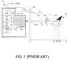
- FIG. 1depicts an exemplary TOF system, as described in U.S. Pat. No. 6,323,942 entitled “CMOS-Compatible Three-Dimensional Image Sensor IC” (2001), which patent is incorporated herein by reference as further background material.
- TOF system 10can be implemented on a single IC 110 , without moving parts and with relatively few off-chip components.
- System 100includes a two-dimensional array 130 of Z pixel detectors 140 , each of which has dedicated circuitry 150 for processing detection charge output by the associated detector.
- pixel array 130might include 100 ⁇ 100 pixels 140 , and thus include 100 ⁇ 100 processing circuits 150 .
- IC 110preferably also includes a microprocessor or microcontroller unit 160 , memory 170 (which preferably includes random access memory or RAM and read-only memory or ROM), a high speed distributable clock 180 , and various computing and input/output (I/O) circuitry 190 .
- controller unit 160may perform distance to object and object velocity calculations, which may be output as DATA.
- a source of optical energy 120is periodically energized and emits optical energy S 1 via lens 125 toward an object target 20 .
- the optical energyis light, for example emitted by a laser diode or LED device 120 .
- Some of the emitted optical energywill be reflected off the surface of target object 20 as reflected energy S 2 .
- This reflected energypasses through an aperture field stop and lens, collectively 135 , and will fall upon two-dimensional array 130 of pixel detectors 140 where a depth or Z image is formed.
- each imaging pixel detector 140captures time-of-flight (TOF) required for optical energy transmitted by emitter 120 to reach target object 20 and be reflected back for detection by two-dimensional sensor array 130 . Using this TOF information, distances Z can be determined as part of the DATA signal that can be output elsewhere, as needed.
- TOFtime-of-flight
- Emitted optical energy S 1 traversing to more distant surface regions of target object 20 , e.g., Z 3 , before being reflected back toward system 100will define a longer time-of-flight than radiation falling upon and being reflected from a nearer surface portion of the target object (or a closer target object), e.g., at distance Z 1 .
- TOF sensor system 10can acquire three-dimensional images of a target object in real time, simultaneously acquiring both luminosity data (e.g., signal brightness amplitude) and true TOF distance (Z) measurements of a target object or scene.
- Z pixel detectors in Canesta-type TOF systemshave additive signal properties in that each individual pixel acquires vector data in the form of luminosity information and also in the form of Z distance information. While the system of FIG. 1 can measure Z, the nature of Z detection according to the first described embodiment of the '942 patent does not lend itself to use with the present invention because the Z-pixel detectors do not exhibit a signal additive characteristic.
- a more useful class of TOF sensor systems whose Z-detection does exhibit a signal additive characteristicare so-called phase-sensing TOF systems. Most current Canesta, Inc. Z-pixel detectors operate with this characteristic.
- Canesta, Inc. systemsdetermine TOF and construct a depth image by examining relative phase shift between the transmitted light signals S 1 having a known phase, and signals S 2 reflected from the target object.
- phase-type TOF systemsare described in several U.S. patents assigned to Canesta, Inc., assignee herein, including U.S. Pat. No. 6,515,740 “Methods for CMOS-Compatible Three-Dimensional Imaging Sensing Using Quantum Efficiency Modulation”, U.S. Pat. No. 6,906,793 entitled Methods and Devices for Charge Management for Three Dimensional Sensing, U.S. Pat. No.
- FIG. 2Ais based upon above-noted U.S. Pat. No. 6,906,793 and depicts an exemplary phase-type TOF system in which phase shift between emitted and detected signals, respectively, S 1 and S 2 provides a measure of distance Z to target object 20 .
- Emitter 120preferably is at least one LED or laser diode(s) emitting low power (e.g., perhaps 1 W) periodic waveform, producing optical energy emissions of known frequency (perhaps a few dozen MHz) for a time period known as the shutter time (perhaps 10 ms).
- low powere.g., perhaps 1 W
- optical energy emissionsof known frequency (perhaps a few dozen MHz) for a time period known as the shutter time (perhaps 10 ms).
- phase shift ⁇between emitted and detected signals, S 1 , S 2 .
- the phase shift ⁇ datacan be processed to yield desired Z depth information.
- pixel detection currentcan be integrated to accumulate a meaningful detection signal, used to form a depth image. In this fashion, TOF system 100 can capture and provide Z depth information at each pixel detector 140 in sensor array 130 for each frame of acquired data.
- pixel detection informationis captured at at least two discrete phases, preferably 0° and 90°, and is processed to yield Z data.
- some portion of incoming optical energy received by a specific pixel 140 within array 130will in fact be optical energy intended for another pixel within the array. What seems to occur is that within the pixel sensor array, some incoming optical energy reflects off shiny surfaces of the IC structure containing the array, typically reflective polysilicon traces and metal. The undesired result is that incoming optical energy that ideally would be sensed by a single pixel is instead reflected internally and is sensed by many pixels. Such internal reflections contribute to what is termed haze. This haze results from detection output signals being generated by pixels in the array other than the pixel that was intended to directly receive the incoming optical energy.
- stray lightwill be used to refer to such misdirected optical energy, which manifests as a haze.
- the magnitude of stray lightis of no cause for concern. But in high performance TOF systems, such parasitic stray light and resultant haze can contribute to substantial measurement error in that wrong values of range Z will result from errors in detected phase-shift.
- the present inventionprovides mechanisms, implementable in hardware and/or software, to substantially eliminate such stray light error.
- Haze-type phase shift error due to stray light reflections in a TOF system including a phase-type TOF systemis reduced in several ways.
- hazeseems to result substantially from stray light reflection, with little or no contribution from cross-talk between pixels in the pixel array.
- magnitude of the stray light reflectionspreferably is reduced by reducing surface reflectivity within the IC containing the sensor array. Reflectivity is reduced in some embodiments by coating the uppermost surface of the array structure with black ink or the like, leaving of course unpainted window areas overlying the light sensitive regions of the array.
- the unpainted window areaspreferably are somewhat oversized relative to the underlying light sensitive regions because incoming optical energy may arrive at an angle relative to the plane of the array. Such inking or painting can help reduce stray light reflections and undesired haze.
- correction datais determined for less than each individual pixel in the array.
- differential valuesmay be acquired for a plurality (but not necessarily all) pixel sensors in the TOF system pixel sensor array responsive to an input pulse of optical energy.
- a correction term for the differential value for each pixel in the plurality of pixel sensorsis computed, based on the acquired values such that phase-shift error is substantially reduced.
- phase-shift error due to stray light reflectioncan be reduced by as much as a factor of five.
- each pixel sensor correction termis computed from a sum of acquired differential values, and in other embodiments, a common or same correction term is used for each of the plurality of pixel sensors.
- response from at least some if not from each pixel in the TOF system pixel sensor arrayis stored in response to an input of pulsed optical energy.
- the pulsed optical energyis intended to elicit a system pixel sensor array response indicative of light haze.
- the pulsed response optical energy inputmay be modeled in the form of an idealized pulse, a pulse having at lease one base pedestal parameter that varies with location, or some combination of each.
- the response of various, if not all, pixels in the array to the pulsed inputis recorded and a correction value is assigned to various pixels in the array, if not to each individual pixel in the array. In this fashion the mal-effects from reflected optical energy within the array are reduced.
- More sophisticated correctionpreferably provides array-location-dependent models, in which the amount of haze is a function of pixel detector (row, column) location within the pixel array, as well as the location of the optical energy light falling on the array. Modeling can include variations in pulse response base value. Although one can provide on-chip color filters or micro-lens to further reduce partial reflections the residual partial reflections can still unduly interfere with generation of reliable TOF system data, and should be reduced according to embodiments of the present invention.
- Other embodimentsfurther reduce mal-effects of stray radiation by coating otherwise reflective regions of the pixel sensor array with a non-reflective surface, leaving openings or windows for regions intended to pass incoming optical energy to the underlying pixel detectors.
- Still other embodimentsreducing the effect of reflections in the lens and other elements in the optical path of the TOF system.
- Thispreferably includes coating the lens and other transmissive elements with anti reflective coating, and/or by designing the optical path in such that stray reflections do not fall upon the sensor array.
- FIG. 1depicts a time-of-flight (TOF) range finding system, according to the prior art
- FIG. 2Adepicts a phase-based TOF range finding system whose Z-pixels exhibit additive signal properties, according to the prior art
- FIGS. 2B and 2Cdepict phase-shifted signals associated with the TOF range finding system of FIG. 2A , according to the prior art
- FIG. 3Adepicts spatial impulse response data collection with a TOF system, according to embodiments of the present invention
- FIG. 3Bdepicts response across an array of detectors in a TOF system to a spatial impulse of light as depicted in FIG. 3A ;
- FIG. 3Cdepicts an elevation plot of the spatial impulse response data shown in FIG. 3B ;
- FIG. 3Dis a three-dimensional vector representation of phase differential values for a pixel in a detector array, according to an embodiment of the present invention.
- FIG. 3Edepicts stray light reflection haze, as addressed by embodiments of the present invention.
- FIGS. 3F-3Idepict exemplary models of responses to optical energy spatial impulses with which to acquire and store haze-reducing data, according to embodiments of the present invention
- FIG. 4depicts exemplary mechanical reduction of stray light reflection in a pixel detector array using windowed inking, according to an embodiment of the present invention.
- FIG. 5depicts a phase-shift type TOF range finding system with reduced stray light reflection characteristics, according to embodiments of the present invention.
- Stray lightcan be due to a number of sources and can have a number of characteristics. Stray light may arise from focus error, and/or haze or reflections in lens 135 in FIG. 1 . Accordingly in FIG. 3A (and in FIG. 5 ), lens 135 ′ has anti-reflective coating(s), As a result, stray light effects that in FIG. 1 would arise from reflections from the lens-facing surface of IC 110 , which result in light being reflected back towards lens 135 and then again towards array 130 on IC 110 are reduced, thanks to lens 135 ′. Such reflection effects can be exacerbated if the pixel structures have a high amount of reflective metal, as is often the case in TOF systems.
- Reference numeral 100denotes that TOF system 100 in FIG.
- TOF system 100preferably has a well designed optical path such that remaining reflections within the optical path tend to be directed other than toward the sensor array. While such techniques can somewhat reduce reflections, nonetheless high performance TOF systems may still be subject to substantial depth measurement error due to reflections.
- reflected optical energy from a bright section in the imaged target objectcontributes to an undesired ghost image.
- Such mal-effectscan generally be reduced by careful control of the reflecting surfaces of lens 135 ′.
- flat surfaces within the lens(which may be more complex than depicted in FIG. 3A ) can cause ghost images from light reflected off IC 110 .
- ghost imagescan be substantially removed by eliminating such surfaces and by practicing careful optical design.
- reference numeral 135 ′distinguishes this lens from lens 135 in the prior art system of FIG. 1 in which anti-reflective measures were not included, and TOF system 100 includes careful optical design, to reduce likelihood of reflections falling upon sensor array 130 .
- the present inventionrecognizes that such haze can usually be modeled as a fraction of the overall optical energy reaching the sensor array, which refraction is redistributed equally amongst all sensor pixels 140 in the array.
- an impulse of lightis directed toward a pixel within the pixel array, and the detection signal from each pixel is examined.
- the pixel directly receiving the light impulseshould output a detection signal, but internal reflections result in many or not all pixels outputting a detection signal responsive to the light impulse.
- Some embodiments of the present inventionpresent a complexly modeled light impulse response, perhaps an impulse formed on a pedestal preferably having at least one variable pedestal parameter, for example pedestal offset, pedestal ripple, pedestal ripple shape, pedestal ripple duration, etc.
- the individual pixel output detection signalsare examined responsive to different input pulses until, perhaps by trial-and-error, a best result is obtained, e.g., minimal haze.
- a correction signal coefficientcan then be defined, either on a per pixel basis, or perhaps on a super-pixel basis, where a super-pixel is defined as a pixel plus neighboring pixels within a predetermined radius of pixels.
- the correctional signal coefficientspreferably are stored within the IC containing the pixel array, perhaps within on-chip memory.
- the embodiments of the present inventionform a corrective filter that processes the actual, hazy, responsive of a pixel array, and improves the resultant data using appropriate corrective coefficient data that has been pre-determined and perhaps stored on-chip.
- FIG. 3Ashows a configuration used to confirm the nature of stray light caused background haze for a pixel array, according to embodiments of the present invention.
- the function of the configuration of FIG. 3Ais to direct an impulse of light to a single pixel 140 (pixel P xy ) in pixel array 130 , and to then examine the effect of this optical energy on other pixels in the array.
- a highly reflective target object 20e.g., a mirror, is used to reflect back into pixel P xy in sensor array 130 an impulse of light generated by TOF system emitter 120 .
- the target object 20can be replaced with a small but bright light source 20 ′ whose emitted optical energy ends up focused upon pixel P xy in pixel sensor array 130 .
- the small but bright light impulse light source 20 ′eliminates use of TOF system emitter 120 during light impulse data acquisition.
- FIG. 3Bdepicts pixel sensor 130 response to the light impulse in the vertical axis, across pixel locations in the x-y plane for an array 130 comprising 150 ⁇ 200 pixels.
- FIG. 3Cis an elevation plot for the same data of FIG. 2B . As seen from the data of FIGS. 3B and 3C , there is a background haze of about 10 counts magnitude throughout the array, plus the 65 count response from the targeted pixel. The background 10 count response is like a haze that is distributed evenly across the pixel array. A similar 10 count haze data would result regardless of at which specific pixel the bright light impulse was directed.
- FIG. 3Ddepicts a practical application of the above test observations on the measured phase vector V xy of a TOF pixel P xy in pixel sensor array 130 in FIG. 3A .
- FIG. 3Dalso depicts vectors V a , V b , V c for pixels P a , P b , P c .
- the contribution E to the phase vector from optical energy (or light) intended for other pixelsis represented as:
- the values of X xy and Y xyrepresent the 0° and 90° phase differential values for pixel P xy .
- implementing a method per equations (1), (2), (3), and (4)involves first acquiring the differential values for the pixel detectors in the sensor array of a TOF system. Next, on a per-pixel basis, one computes a correction term for the differential value based on the acquired values, such that mal-effects of stray light reflection are substantially reduced.
- the correction datamay be stored in memory, e.g., memory 170 , perhaps as a look-up-table 200 .
- detected phase shift error due to reflectionis reduced by a factor of five.
- An exemplary such modelis described with respect to FIGS. 3E-3I .
- Preferable optical system 135 ′is designed so as to make any produced haze obey this simple model, e.g., as depicted in FIGS. 3B and 3C .
- FIG. 3Edepicts the manifestation of internal partial reflections as a haze 400 surround a bright or highly reflective spot 410 on the acquired image 420 . Portions of this undesired haze are found over the entire acquired image. Left uncorrected, this haze produces errors in radial Z distances in DATA′ in phase-based TOF systems, e.g., FIG. 3A and FIG. 5 .
- a simple stationary impulse function modele.g., 430 in FIG. 3F , is used to synthesize the haze, by directing such an impulse of optical energy toward array 130 and examining detection output signals from the various pixels 140 .
- Pixel haze values responsive to the input pulseare stored, e.g., in memory 170 , perhaps in memory region 200 , and are used during actual TOF system run-time to make corrections to pixel output values.
- Haze-type phase shift error due to stray light reflections in a phase-type TOF systemcan be reduced by acquiring and storing differential values for a plurality (but not necessarily all) pixel sensors in TOF system pixel array 130 or 130 ′.
- a correction term for the differential value for each pixel in the plurality of pixel sensorsis computed, based on the acquired values such that phase-shift error is substantially reduced.
- each pixel sensor correction termis computed from a sum of acquired differential values, and in other embodiments, a common or same correction term is used for each of the plurality of pixel sensors.
- this simple modelcan reduce haze due to partial reflection by a factor of perhaps five.
- more sophisticated modelingincludes providing a location-dependent model, where the amount of haze depends upon pixel detector location within the pixel array, as well as location of the haze generating impulses. Further, the model can now have more advanced structure, e.g., rather than a constant pedestal value, a model 440 with a ripple pedestal 450 as shown by FIG. 3G .
- pixel array 130 or 130 ′is subjected to an impulse of light whose response is shaped for example as shown in FIG. 3G .
- the light impulseto the pixel array in a sequence other than row 1, col. 1, row 1, col. 2, and indeed one could present more than one light impulse simultaneously to different pixels in the array.
- FIGS. 3H and 3Idepict generically further exemplary modeling options.
- an input pulse response 470 of optical energymay have varied rise and/or fall times relative to a more idealized pulse 470 .
- such shapesmay also have complex pedestal features 180 .
- the intentis, during testing, to arrive at a well designed and shaped input pulse of optical energy with which to measure haze across the pixel array.
- haze data collected responsive to a well shaped light impulseshould produce a correction table 200 that can reduce the haze contribution greater than a factor of five, preferably by a larger factor, perhaps a factor of about 20 to about 25 times.
- DATA′ generated with such haze reductionwill be more reliably accurate than if no haze correction measures were employed to combat partial reflection error.
- the design challengeis to create and use an impulse function whose structure enables a haze correction model that is compact (in terms of memory and computational constraints) and is efficient at runtime.
- a haze correction modelthat is compact (in terms of memory and computational constraints) and is efficient at runtime.
- Preferably such modelanalytically describes the relevant haze correction term over the entire array of pixel detectors.
- Such modelcan perhaps be-derived by curve fitting response data to at least two possible models and then selecting the most appropriate model.
- the resultant modelis selected both for compactness and run time efficiency.
- optical system 135 ′allows for the simplest and most compact model possible subject to optical systems size and cost constraints.
- partial reflections within sensor array 130 due to incoming optical radiation (S IN ) reflecting off metal polysilicon traces at the upper region of the surface of IC 110are reduced in phase-based TOF system 100 .
- Some of this undesired reflectionis reduced by making the polysilicon traces less reflective, for example by covering the upper surface of the array with a non-reflective coating of black ink or the like, leaving uncovered windows to allow optical energy to reach light sensitive regions of the pixels.
- FIG. 4depicts an exemplary region of an array 130 ′ of pixel detectors 140 and associated circuitry 150 , which lie beneath a layer of dark ink or the like 210 formed on the upper surface of the array structure.
- this anti-reflective (e.g., black) ink layer 210are window openings 210 , such that an opening 210 overlies and is somewhat larger in area than the light sensitive portion of a pixel 140 .
- Also disposed beneath layer 210 and not shown in FIG. 4will be the electronic circuitry 150 associated with each pixel 140 , as well as various polysilicon traces, metal, etc.
- the metal layerswill have been covered with at least one layer of protective material, e.g., SiO 2 and SiN during fabrication.
- Window openings 210are intentional oversized somewhat relative to the area of the light sensitive portion of the underlying pixel because incoming optical radiation (shown as zig-zag arrowed lines) may impinge upon the detector array at an angle. But for oversizing, some optical energy might be lost due to shadowing caused by the edge height at the window.
- FIG. 5depicts a phase-shift type TOF system 100 whose memory 170 preferably includes software 200 that when executed, e.g., by microprocessor 160 or other processor resource, carries out reduction of stray light reflection and associated correction to phase-shift error, according to any or all of the embodiments described herein.
- the pixel array in FIG. 5is denoted 130 ′ to indicate that preferably (but not necessarily) an anti-reflective black or dark inked or painted coating 210 is formed on the upper surface of the array, defining window areas 220 , as described with respect to FIG. 4 .
- like-referenced elements or components in FIG. 5 to elements or components in FIG. 3Amay be the same or identical elements or components.
Landscapes
- Engineering & Computer Science (AREA)
- Physics & Mathematics (AREA)
- Computer Networks & Wireless Communication (AREA)
- General Physics & Mathematics (AREA)
- Radar, Positioning & Navigation (AREA)
- Remote Sensing (AREA)
- Electromagnetism (AREA)
- Optical Radar Systems And Details Thereof (AREA)
Abstract
Description
θ=2·ω·Z/C=2·(2·π·f)·Z/C (1)
Z=θ·C/2·ω=θ·C/(2·2·f·π) (2)
ZAIR=C/(2·f) (3)
{circumflex over (V)}xy={right arrow over (V)}xy−{right arrow over (E)} (2)
Claims (7)
Priority Applications (2)
| Application Number | Priority Date | Filing Date | Title |
|---|---|---|---|
| US12/384,949US8194233B2 (en) | 2008-04-11 | 2009-04-10 | Method and system to reduce stray light reflection error in time-of-flight sensor arrays |
| US13/461,443US8675182B2 (en) | 2008-04-11 | 2012-05-01 | Method and system to reduce stray light reflection error in time-of-flight sensor arrays |
Applications Claiming Priority (3)
| Application Number | Priority Date | Filing Date | Title |
|---|---|---|---|
| US12410408P | 2008-04-11 | 2008-04-11 | |
| US20359908P | 2008-12-26 | 2008-12-26 | |
| US12/384,949US8194233B2 (en) | 2008-04-11 | 2009-04-10 | Method and system to reduce stray light reflection error in time-of-flight sensor arrays |
Related Child Applications (1)
| Application Number | Title | Priority Date | Filing Date |
|---|---|---|---|
| US13/461,443DivisionUS8675182B2 (en) | 2008-04-11 | 2012-05-01 | Method and system to reduce stray light reflection error in time-of-flight sensor arrays |
Publications (2)
| Publication Number | Publication Date |
|---|---|
| US20120008128A1 US20120008128A1 (en) | 2012-01-12 |
| US8194233B2true US8194233B2 (en) | 2012-06-05 |
Family
ID=45438359
Family Applications (2)
| Application Number | Title | Priority Date | Filing Date |
|---|---|---|---|
| US12/384,949ActiveUS8194233B2 (en) | 2008-04-11 | 2009-04-10 | Method and system to reduce stray light reflection error in time-of-flight sensor arrays |
| US13/461,443ActiveUS8675182B2 (en) | 2008-04-11 | 2012-05-01 | Method and system to reduce stray light reflection error in time-of-flight sensor arrays |
Family Applications After (1)
| Application Number | Title | Priority Date | Filing Date |
|---|---|---|---|
| US13/461,443ActiveUS8675182B2 (en) | 2008-04-11 | 2012-05-01 | Method and system to reduce stray light reflection error in time-of-flight sensor arrays |
Country Status (1)
| Country | Link |
|---|---|
| US (2) | US8194233B2 (en) |
Cited By (17)
| Publication number | Priority date | Publication date | Assignee | Title |
|---|---|---|---|---|
| US20110188775A1 (en)* | 2010-02-01 | 2011-08-04 | Microsoft Corporation | Single Image Haze Removal Using Dark Channel Priors |
| US20140205192A1 (en)* | 2011-08-30 | 2014-07-24 | Fujitsu Limited | Image defogging method and system |
| US9092665B2 (en) | 2013-01-30 | 2015-07-28 | Aquifi, Inc | Systems and methods for initializing motion tracking of human hands |
| US9098739B2 (en) | 2012-06-25 | 2015-08-04 | Aquifi, Inc. | Systems and methods for tracking human hands using parts based template matching |
| US9111135B2 (en) | 2012-06-25 | 2015-08-18 | Aquifi, Inc. | Systems and methods for tracking human hands using parts based template matching using corresponding pixels in bounded regions of a sequence of frames that are a specified distance interval from a reference camera |
| US9129155B2 (en) | 2013-01-30 | 2015-09-08 | Aquifi, Inc. | Systems and methods for initializing motion tracking of human hands using template matching within bounded regions determined using a depth map |
| US9298266B2 (en) | 2013-04-02 | 2016-03-29 | Aquifi, Inc. | Systems and methods for implementing three-dimensional (3D) gesture based graphical user interfaces (GUI) that incorporate gesture reactive interface objects |
| US9310891B2 (en) | 2012-09-04 | 2016-04-12 | Aquifi, Inc. | Method and system enabling natural user interface gestures with user wearable glasses |
| US9507417B2 (en) | 2014-01-07 | 2016-11-29 | Aquifi, Inc. | Systems and methods for implementing head tracking based graphical user interfaces (GUI) that incorporate gesture reactive interface objects |
| US9504920B2 (en) | 2011-04-25 | 2016-11-29 | Aquifi, Inc. | Method and system to create three-dimensional mapping in a two-dimensional game |
| US9600078B2 (en) | 2012-02-03 | 2017-03-21 | Aquifi, Inc. | Method and system enabling natural user interface gestures with an electronic system |
| US9619105B1 (en) | 2014-01-30 | 2017-04-11 | Aquifi, Inc. | Systems and methods for gesture based interaction with viewpoint dependent user interfaces |
| US9798388B1 (en) | 2013-07-31 | 2017-10-24 | Aquifi, Inc. | Vibrotactile system to augment 3D input systems |
| US9857868B2 (en) | 2011-03-19 | 2018-01-02 | The Board Of Trustees Of The Leland Stanford Junior University | Method and system for ergonomic touch-free interface |
| US10191154B2 (en) | 2016-02-11 | 2019-01-29 | Massachusetts Institute Of Technology | Methods and apparatus for time-of-flight imaging |
| US10190983B2 (en) | 2016-04-15 | 2019-01-29 | Massachusetts Institute Of Technology | Methods and apparatus for fluorescence lifetime imaging with pulsed light |
| US10210643B2 (en)* | 2016-01-20 | 2019-02-19 | Canon Kabushiki Kaisha | Image processing apparatus, image processing method, and storage medium storing a program that generates an image from a captured image in which an influence of fine particles in an atmosphere has been reduced |
Families Citing this family (43)
| Publication number | Priority date | Publication date | Assignee | Title |
|---|---|---|---|---|
| US8194233B2 (en) | 2008-04-11 | 2012-06-05 | Microsoft Corporation | Method and system to reduce stray light reflection error in time-of-flight sensor arrays |
| US8964028B2 (en)* | 2009-12-21 | 2015-02-24 | Mesa Imaging Ag | Stray light compensation method and system for time of flight camera systems |
| US9753128B2 (en)* | 2010-07-23 | 2017-09-05 | Heptagon Micro Optics Pte. Ltd. | Multi-path compensation using multiple modulation frequencies in time of flight sensor |
| US10890965B2 (en)* | 2012-08-15 | 2021-01-12 | Ebay Inc. | Display orientation adjustment using facial landmark information |
| JP6061616B2 (en)* | 2012-10-29 | 2017-01-18 | キヤノン株式会社 | Measuring apparatus, control method therefor, and program |
| LU92173B1 (en)* | 2013-03-20 | 2014-09-22 | Iee Sarl | Distance determination method |
| US9497440B2 (en) | 2013-04-05 | 2016-11-15 | Microsoft Technology Licensing, Llc | Burst-mode time-of-flight imaging |
| US9405008B2 (en)* | 2013-05-17 | 2016-08-02 | Massachusetts Institute Of Technology | Methods and apparatus for multi-frequency camera |
| US10230934B2 (en) | 2013-06-14 | 2019-03-12 | Microsoft Tehcnology Licensing, Llc | Depth map correction using lookup tables |
| US11143749B2 (en) | 2014-05-23 | 2021-10-12 | Signify Holding B.V. | Object detection system and method |
| US9910155B2 (en)* | 2014-09-29 | 2018-03-06 | ARETé ASSOCIATES | Tilted image plane lidar |
| US11972586B2 (en) | 2015-02-13 | 2024-04-30 | Carnegie Mellon University | Agile depth sensing using triangulation light curtains |
| US11493634B2 (en) | 2015-02-13 | 2022-11-08 | Carnegie Mellon University | Programmable light curtains |
| US11747135B2 (en) | 2015-02-13 | 2023-09-05 | Carnegie Mellon University | Energy optimized imaging system with synchronized dynamic control of directable beam light source and reconfigurably masked photo-sensor |
| US11425357B2 (en)* | 2015-02-13 | 2022-08-23 | Carnegie Mellon University | Method for epipolar time of flight imaging |
| US9747519B2 (en) | 2015-04-24 | 2017-08-29 | Microsoft Technology Licensing, Llc | Classifying ambiguous image data |
| JP6299668B2 (en)* | 2015-05-13 | 2018-03-28 | 信越半導体株式会社 | How to evaluate haze |
| DE102015109775B3 (en)* | 2015-06-18 | 2016-09-22 | RobArt GmbH | Optical triangulation sensor for distance measurement |
| US9910276B2 (en) | 2015-06-30 | 2018-03-06 | Microsoft Technology Licensing, Llc | Diffractive optical elements with graded edges |
| US10670862B2 (en) | 2015-07-02 | 2020-06-02 | Microsoft Technology Licensing, Llc | Diffractive optical elements with asymmetric profiles |
| US9864208B2 (en) | 2015-07-30 | 2018-01-09 | Microsoft Technology Licensing, Llc | Diffractive optical elements with varying direction for depth modulation |
| US10038840B2 (en) | 2015-07-30 | 2018-07-31 | Microsoft Technology Licensing, Llc | Diffractive optical element using crossed grating for pupil expansion |
| US10073278B2 (en) | 2015-08-27 | 2018-09-11 | Microsoft Technology Licensing, Llc | Diffractive optical element using polarization rotation grating for in-coupling |
| DE102015114883A1 (en) | 2015-09-04 | 2017-03-09 | RobArt GmbH | Identification and localization of a base station of an autonomous mobile robot |
| US10429645B2 (en) | 2015-10-07 | 2019-10-01 | Microsoft Technology Licensing, Llc | Diffractive optical element with integrated in-coupling, exit pupil expansion, and out-coupling |
| US10241332B2 (en) | 2015-10-08 | 2019-03-26 | Microsoft Technology Licensing, Llc | Reducing stray light transmission in near eye display using resonant grating filter |
| DE102015119501A1 (en) | 2015-11-11 | 2017-05-11 | RobArt GmbH | Subdivision of maps for robot navigation |
| US10234686B2 (en) | 2015-11-16 | 2019-03-19 | Microsoft Technology Licensing, Llc | Rainbow removal in near-eye display using polarization-sensitive grating |
| DE102015119865B4 (en) | 2015-11-17 | 2023-12-21 | RobArt GmbH | Robot-assisted processing of a surface using a robot |
| DE102015121666B3 (en) | 2015-12-11 | 2017-05-24 | RobArt GmbH | Remote control of a mobile, autonomous robot |
| DE102016102644A1 (en) | 2016-02-15 | 2017-08-17 | RobArt GmbH | Method for controlling an autonomous mobile robot |
| JP7073336B2 (en) | 2016-08-05 | 2022-05-23 | ロブアート ゲーエムベーハー | How to control an autonomous mobile robot |
| US10108014B2 (en)* | 2017-01-10 | 2018-10-23 | Microsoft Technology Licensing, Llc | Waveguide display with multiple focal depths |
| EP3974934A1 (en) | 2017-03-02 | 2022-03-30 | Robart GmbH | Method for controlling an autonomous mobile robot |
| DE102017109219A1 (en) | 2017-04-28 | 2018-10-31 | RobArt GmbH | Method for robot navigation |
| CN107607960B (en)* | 2017-10-19 | 2024-12-20 | 深圳市欢创科技股份有限公司 | Optical distance measurement method and device |
| JP7252876B2 (en)* | 2019-10-16 | 2023-04-05 | 株式会社アドバンテスト | Optical test equipment |
| CN110910417B (en)* | 2019-10-29 | 2022-03-29 | 西北工业大学 | Weak and small moving target detection method based on super-pixel adjacent frame feature comparison |
| US11343435B2 (en) | 2019-12-26 | 2022-05-24 | Waymo Llc | Microlensing for real-time sensing of stray light |
| CN111366943B (en)* | 2020-03-25 | 2022-09-09 | 炬佑智能科技(苏州)有限公司 | Flight time ranging system and ranging method thereof |
| CN111352120B (en)* | 2020-03-25 | 2022-09-09 | 炬佑智能科技(苏州)有限公司 | Flight time ranging system and ranging method thereof |
| CN111352121B (en)* | 2020-03-25 | 2021-12-10 | 上海炬佑智能科技有限公司 | Flight time ranging system and ranging method thereof |
| CN112505715B (en)* | 2020-12-08 | 2022-09-27 | 上海炬佑智能科技有限公司 | ToF sensing device and distance detection method thereof |
Citations (4)
| Publication number | Priority date | Publication date | Assignee | Title |
|---|---|---|---|---|
| US6741335B2 (en)* | 1998-03-09 | 2004-05-25 | Otm Technologies Ltd. | Optical translation measurement |
| US20060176467A1 (en)* | 2005-02-08 | 2006-08-10 | Canesta, Inc. | Method and system for automatic gain control of sensors in time-of-flight systems |
| US20070263203A1 (en)* | 2006-05-12 | 2007-11-15 | Voith Patent Gmbh | Device and process for optical distance measurement |
| US7554652B1 (en)* | 2008-02-29 | 2009-06-30 | Institut National D'optique | Light-integrating rangefinding device and method |
Family Cites Families (11)
| Publication number | Priority date | Publication date | Assignee | Title |
|---|---|---|---|---|
| US4630910A (en) | 1984-02-16 | 1986-12-23 | Robotic Vision Systems, Inc. | Method of measuring in three-dimensions at high speed |
| US4796997A (en) | 1986-05-27 | 1989-01-10 | Synthetic Vision Systems, Inc. | Method and system for high-speed, 3-D imaging of an object at a vision station |
| EP2026035A2 (en) | 1998-12-16 | 2009-02-18 | 3DV Systems Ltd. | 3D camera for distance measurements |
| US8035612B2 (en) | 2002-05-28 | 2011-10-11 | Intellectual Ventures Holding 67 Llc | Self-contained interactive video display system |
| US7259747B2 (en) | 2001-06-05 | 2007-08-21 | Reactrix Systems, Inc. | Interactive video display system |
| US7710391B2 (en) | 2002-05-28 | 2010-05-04 | Matthew Bell | Processing an image utilizing a spatially varying pattern |
| US7348963B2 (en) | 2002-05-28 | 2008-03-25 | Reactrix Systems, Inc. | Interactive video display system |
| US7170492B2 (en) | 2002-05-28 | 2007-01-30 | Reactrix Systems, Inc. | Interactive video display system |
| US7576727B2 (en) | 2002-12-13 | 2009-08-18 | Matthew Bell | Interactive directed light/sound system |
| WO2005041579A2 (en) | 2003-10-24 | 2005-05-06 | Reactrix Systems, Inc. | Method and system for processing captured image information in an interactive video display system |
| US8194233B2 (en) | 2008-04-11 | 2012-06-05 | Microsoft Corporation | Method and system to reduce stray light reflection error in time-of-flight sensor arrays |
- 2009
- 2009-04-10USUS12/384,949patent/US8194233B2/enactiveActive
- 2012
- 2012-05-01USUS13/461,443patent/US8675182B2/enactiveActive
Patent Citations (4)
| Publication number | Priority date | Publication date | Assignee | Title |
|---|---|---|---|---|
| US6741335B2 (en)* | 1998-03-09 | 2004-05-25 | Otm Technologies Ltd. | Optical translation measurement |
| US20060176467A1 (en)* | 2005-02-08 | 2006-08-10 | Canesta, Inc. | Method and system for automatic gain control of sensors in time-of-flight systems |
| US20070263203A1 (en)* | 2006-05-12 | 2007-11-15 | Voith Patent Gmbh | Device and process for optical distance measurement |
| US7554652B1 (en)* | 2008-02-29 | 2009-06-30 | Institut National D'optique | Light-integrating rangefinding device and method |
Cited By (20)
| Publication number | Priority date | Publication date | Assignee | Title |
|---|---|---|---|---|
| US8340461B2 (en)* | 2010-02-01 | 2012-12-25 | Microsoft Corporation | Single image haze removal using dark channel priors |
| US20110188775A1 (en)* | 2010-02-01 | 2011-08-04 | Microsoft Corporation | Single Image Haze Removal Using Dark Channel Priors |
| US9857868B2 (en) | 2011-03-19 | 2018-01-02 | The Board Of Trustees Of The Leland Stanford Junior University | Method and system for ergonomic touch-free interface |
| US9504920B2 (en) | 2011-04-25 | 2016-11-29 | Aquifi, Inc. | Method and system to create three-dimensional mapping in a two-dimensional game |
| US9189830B2 (en)* | 2011-08-30 | 2015-11-17 | Fujitsu Limited | Image defogging method and system |
| US20140205192A1 (en)* | 2011-08-30 | 2014-07-24 | Fujitsu Limited | Image defogging method and system |
| US9600078B2 (en) | 2012-02-03 | 2017-03-21 | Aquifi, Inc. | Method and system enabling natural user interface gestures with an electronic system |
| US9111135B2 (en) | 2012-06-25 | 2015-08-18 | Aquifi, Inc. | Systems and methods for tracking human hands using parts based template matching using corresponding pixels in bounded regions of a sequence of frames that are a specified distance interval from a reference camera |
| US9098739B2 (en) | 2012-06-25 | 2015-08-04 | Aquifi, Inc. | Systems and methods for tracking human hands using parts based template matching |
| US9310891B2 (en) | 2012-09-04 | 2016-04-12 | Aquifi, Inc. | Method and system enabling natural user interface gestures with user wearable glasses |
| US9129155B2 (en) | 2013-01-30 | 2015-09-08 | Aquifi, Inc. | Systems and methods for initializing motion tracking of human hands using template matching within bounded regions determined using a depth map |
| US9092665B2 (en) | 2013-01-30 | 2015-07-28 | Aquifi, Inc | Systems and methods for initializing motion tracking of human hands |
| US9298266B2 (en) | 2013-04-02 | 2016-03-29 | Aquifi, Inc. | Systems and methods for implementing three-dimensional (3D) gesture based graphical user interfaces (GUI) that incorporate gesture reactive interface objects |
| US9798388B1 (en) | 2013-07-31 | 2017-10-24 | Aquifi, Inc. | Vibrotactile system to augment 3D input systems |
| US9507417B2 (en) | 2014-01-07 | 2016-11-29 | Aquifi, Inc. | Systems and methods for implementing head tracking based graphical user interfaces (GUI) that incorporate gesture reactive interface objects |
| US9619105B1 (en) | 2014-01-30 | 2017-04-11 | Aquifi, Inc. | Systems and methods for gesture based interaction with viewpoint dependent user interfaces |
| US10210643B2 (en)* | 2016-01-20 | 2019-02-19 | Canon Kabushiki Kaisha | Image processing apparatus, image processing method, and storage medium storing a program that generates an image from a captured image in which an influence of fine particles in an atmosphere has been reduced |
| US10191154B2 (en) | 2016-02-11 | 2019-01-29 | Massachusetts Institute Of Technology | Methods and apparatus for time-of-flight imaging |
| US10190983B2 (en) | 2016-04-15 | 2019-01-29 | Massachusetts Institute Of Technology | Methods and apparatus for fluorescence lifetime imaging with pulsed light |
| US10337993B2 (en) | 2016-04-15 | 2019-07-02 | Massachusetts Institute Of Technology | Methods and apparatus for fluorescence lifetime imaging with periodically modulated light |
Also Published As
| Publication number | Publication date |
|---|---|
| US20120008128A1 (en) | 2012-01-12 |
| US8675182B2 (en) | 2014-03-18 |
| US20120229790A1 (en) | 2012-09-13 |
Similar Documents
| Publication | Publication Date | Title |
|---|---|---|
| US8194233B2 (en) | Method and system to reduce stray light reflection error in time-of-flight sensor arrays | |
| US11536815B2 (en) | Optoelectronic modules operable to recognize spurious reflections and to compensate for errors caused by spurious reflections | |
| US7379163B2 (en) | Method and system for automatic gain control of sensors in time-of-flight systems | |
| US11536804B2 (en) | Glare mitigation in LIDAR applications | |
| KR102451010B1 (en) | A system for determining the distance to an object | |
| CA2650235C (en) | Distance measuring method and distance measuring element for detecting the spatial dimension of a target | |
| KR20220058947A (en) | processing of lidar images | |
| US10739445B2 (en) | Parallel photon counting | |
| US8988661B2 (en) | Method and system to maximize space-time resolution in a time-of-flight (TOF) system | |
| US20200033478A1 (en) | System and method for determining a distance to an object | |
| JP2018531374A6 (en) | System and method for measuring distance to an object | |
| JP2018531374A (en) | System and method for measuring distance to an object | |
| US11252359B1 (en) | Image compensation for sensor array having bad pixels | |
| US20210165083A1 (en) | Configurable array of single-photon detectors | |
| US12153140B2 (en) | Enhanced depth mapping using visual inertial odometry | |
| JPWO2020066236A1 (en) | Depth acquisition device, depth acquisition method and program | |
| CN116299496A (en) | Method, processing device and storage medium for estimating reflectivity of object | |
| US20230375678A1 (en) | Photoreceiver having thresholded detection | |
| US20230194685A1 (en) | Active/passive pixel current injection and bias testing | |
| US20220283307A1 (en) | Depth sensor calibration using internal reflections | |
| JP6693757B2 (en) | Distance image generating apparatus and method | |
| CN110476080A (en) | Laser radar apparatus and method for being scanned to scan angle and for analyzing processing detector | |
| Peppa | Precision analysis of 3D camera | |
| WO2024132463A1 (en) | Device and method to detect refractive objects | |
| JP2002174683A (en) | Distance information acquisition device and distance information acquisition method |
Legal Events
| Date | Code | Title | Description |
|---|---|---|---|
| AS | Assignment | Owner name:CANESTA, INC., CALIFORNIA Free format text:ASSIGNMENT OF ASSIGNORS INTEREST;ASSIGNOR:BAMJI, CYRUS;REEL/FRAME:025224/0373 Effective date:20101013 | |
| AS | Assignment | Owner name:MICROSOFT CORPORATION, WASHINGTON Free format text:ASSIGNMENT OF ASSIGNORS INTEREST;ASSIGNOR:CANESTA, INC.;REEL/FRAME:025790/0458 Effective date:20101122 | |
| FEPP | Fee payment procedure | Free format text:PAYOR NUMBER ASSIGNED (ORIGINAL EVENT CODE: ASPN); ENTITY STATUS OF PATENT OWNER: LARGE ENTITY | |
| STCF | Information on status: patent grant | Free format text:PATENTED CASE | |
| AS | Assignment | Owner name:MICROSOFT TECHNOLOGY LICENSING, LLC, WASHINGTON Free format text:ASSIGNMENT OF ASSIGNORS INTEREST;ASSIGNOR:MICROSOFT CORPORATION;REEL/FRAME:034564/0001 Effective date:20141014 | |
| FPAY | Fee payment | Year of fee payment:4 | |
| MAFP | Maintenance fee payment | Free format text:PAYMENT OF MAINTENANCE FEE, 8TH YEAR, LARGE ENTITY (ORIGINAL EVENT CODE: M1552); ENTITY STATUS OF PATENT OWNER: LARGE ENTITY Year of fee payment:8 | |
| MAFP | Maintenance fee payment | Free format text:PAYMENT OF MAINTENANCE FEE, 12TH YEAR, LARGE ENTITY (ORIGINAL EVENT CODE: M1553); ENTITY STATUS OF PATENT OWNER: LARGE ENTITY Year of fee payment:12 |