US8194132B2 - System for monitoring an area adjacent a vehicle - Google Patents
System for monitoring an area adjacent a vehicleDownload PDFInfo
- Publication number
- US8194132B2 US8194132B2US11/854,815US85481507AUS8194132B2US 8194132 B2US8194132 B2US 8194132B2US 85481507 AUS85481507 AUS 85481507AUS 8194132 B2US8194132 B2US 8194132B2
- Authority
- US
- United States
- Prior art keywords
- vehicle
- display device
- camera
- camera assembly
- image signal
- Prior art date
- Legal status (The legal status is an assumption and is not a legal conclusion. Google has not performed a legal analysis and makes no representation as to the accuracy of the status listed.)
- Active, expires
Links
Images


Classifications
- B—PERFORMING OPERATIONS; TRANSPORTING
- B60—VEHICLES IN GENERAL
- B60R—VEHICLES, VEHICLE FITTINGS, OR VEHICLE PARTS, NOT OTHERWISE PROVIDED FOR
- B60R1/00—Optical viewing arrangements; Real-time viewing arrangements for drivers or passengers using optical image capturing systems, e.g. cameras or video systems specially adapted for use in or on vehicles
- B60R1/20—Real-time viewing arrangements for drivers or passengers using optical image capturing systems, e.g. cameras or video systems specially adapted for use in or on vehicles
- B60R1/22—Real-time viewing arrangements for drivers or passengers using optical image capturing systems, e.g. cameras or video systems specially adapted for use in or on vehicles for viewing an area outside the vehicle, e.g. the exterior of the vehicle
- B60R1/28—Real-time viewing arrangements for drivers or passengers using optical image capturing systems, e.g. cameras or video systems specially adapted for use in or on vehicles for viewing an area outside the vehicle, e.g. the exterior of the vehicle with an adjustable field of view
- B—PERFORMING OPERATIONS; TRANSPORTING
- B60—VEHICLES IN GENERAL
- B60K—ARRANGEMENT OR MOUNTING OF PROPULSION UNITS OR OF TRANSMISSIONS IN VEHICLES; ARRANGEMENT OR MOUNTING OF PLURAL DIVERSE PRIME-MOVERS IN VEHICLES; AUXILIARY DRIVES FOR VEHICLES; INSTRUMENTATION OR DASHBOARDS FOR VEHICLES; ARRANGEMENTS IN CONNECTION WITH COOLING, AIR INTAKE, GAS EXHAUST OR FUEL SUPPLY OF PROPULSION UNITS IN VEHICLES
- B60K35/00—Instruments specially adapted for vehicles; Arrangement of instruments in or on vehicles
- B60K35/10—Input arrangements, i.e. from user to vehicle, associated with vehicle functions or specially adapted therefor
- B—PERFORMING OPERATIONS; TRANSPORTING
- B60—VEHICLES IN GENERAL
- B60K—ARRANGEMENT OR MOUNTING OF PROPULSION UNITS OR OF TRANSMISSIONS IN VEHICLES; ARRANGEMENT OR MOUNTING OF PLURAL DIVERSE PRIME-MOVERS IN VEHICLES; AUXILIARY DRIVES FOR VEHICLES; INSTRUMENTATION OR DASHBOARDS FOR VEHICLES; ARRANGEMENTS IN CONNECTION WITH COOLING, AIR INTAKE, GAS EXHAUST OR FUEL SUPPLY OF PROPULSION UNITS IN VEHICLES
- B60K35/00—Instruments specially adapted for vehicles; Arrangement of instruments in or on vehicles
- B60K35/20—Output arrangements, i.e. from vehicle to user, associated with vehicle functions or specially adapted therefor
- B60K35/21—Output arrangements, i.e. from vehicle to user, associated with vehicle functions or specially adapted therefor using visual output, e.g. blinking lights or matrix displays
- B60K35/22—Display screens
- B—PERFORMING OPERATIONS; TRANSPORTING
- B60—VEHICLES IN GENERAL
- B60K—ARRANGEMENT OR MOUNTING OF PROPULSION UNITS OR OF TRANSMISSIONS IN VEHICLES; ARRANGEMENT OR MOUNTING OF PLURAL DIVERSE PRIME-MOVERS IN VEHICLES; AUXILIARY DRIVES FOR VEHICLES; INSTRUMENTATION OR DASHBOARDS FOR VEHICLES; ARRANGEMENTS IN CONNECTION WITH COOLING, AIR INTAKE, GAS EXHAUST OR FUEL SUPPLY OF PROPULSION UNITS IN VEHICLES
- B60K35/00—Instruments specially adapted for vehicles; Arrangement of instruments in or on vehicles
- B60K35/20—Output arrangements, i.e. from vehicle to user, associated with vehicle functions or specially adapted therefor
- B60K35/26—Output arrangements, i.e. from vehicle to user, associated with vehicle functions or specially adapted therefor using acoustic output
- B—PERFORMING OPERATIONS; TRANSPORTING
- B60—VEHICLES IN GENERAL
- B60K—ARRANGEMENT OR MOUNTING OF PROPULSION UNITS OR OF TRANSMISSIONS IN VEHICLES; ARRANGEMENT OR MOUNTING OF PLURAL DIVERSE PRIME-MOVERS IN VEHICLES; AUXILIARY DRIVES FOR VEHICLES; INSTRUMENTATION OR DASHBOARDS FOR VEHICLES; ARRANGEMENTS IN CONNECTION WITH COOLING, AIR INTAKE, GAS EXHAUST OR FUEL SUPPLY OF PROPULSION UNITS IN VEHICLES
- B60K35/00—Instruments specially adapted for vehicles; Arrangement of instruments in or on vehicles
- B60K35/20—Output arrangements, i.e. from vehicle to user, associated with vehicle functions or specially adapted therefor
- B60K35/28—Output arrangements, i.e. from vehicle to user, associated with vehicle functions or specially adapted therefor characterised by the type of the output information, e.g. video entertainment or vehicle dynamics information; characterised by the purpose of the output information, e.g. for attracting the attention of the driver
- B—PERFORMING OPERATIONS; TRANSPORTING
- B60—VEHICLES IN GENERAL
- B60K—ARRANGEMENT OR MOUNTING OF PROPULSION UNITS OR OF TRANSMISSIONS IN VEHICLES; ARRANGEMENT OR MOUNTING OF PLURAL DIVERSE PRIME-MOVERS IN VEHICLES; AUXILIARY DRIVES FOR VEHICLES; INSTRUMENTATION OR DASHBOARDS FOR VEHICLES; ARRANGEMENTS IN CONNECTION WITH COOLING, AIR INTAKE, GAS EXHAUST OR FUEL SUPPLY OF PROPULSION UNITS IN VEHICLES
- B60K35/00—Instruments specially adapted for vehicles; Arrangement of instruments in or on vehicles
- B60K35/50—Instruments characterised by their means of attachment to or integration in the vehicle
- B—PERFORMING OPERATIONS; TRANSPORTING
- B60—VEHICLES IN GENERAL
- B60K—ARRANGEMENT OR MOUNTING OF PROPULSION UNITS OR OF TRANSMISSIONS IN VEHICLES; ARRANGEMENT OR MOUNTING OF PLURAL DIVERSE PRIME-MOVERS IN VEHICLES; AUXILIARY DRIVES FOR VEHICLES; INSTRUMENTATION OR DASHBOARDS FOR VEHICLES; ARRANGEMENTS IN CONNECTION WITH COOLING, AIR INTAKE, GAS EXHAUST OR FUEL SUPPLY OF PROPULSION UNITS IN VEHICLES
- B60K35/00—Instruments specially adapted for vehicles; Arrangement of instruments in or on vehicles
- B60K35/60—Instruments characterised by their location or relative disposition in or on vehicles
- B—PERFORMING OPERATIONS; TRANSPORTING
- B60—VEHICLES IN GENERAL
- B60K—ARRANGEMENT OR MOUNTING OF PROPULSION UNITS OR OF TRANSMISSIONS IN VEHICLES; ARRANGEMENT OR MOUNTING OF PLURAL DIVERSE PRIME-MOVERS IN VEHICLES; AUXILIARY DRIVES FOR VEHICLES; INSTRUMENTATION OR DASHBOARDS FOR VEHICLES; ARRANGEMENTS IN CONNECTION WITH COOLING, AIR INTAKE, GAS EXHAUST OR FUEL SUPPLY OF PROPULSION UNITS IN VEHICLES
- B60K35/00—Instruments specially adapted for vehicles; Arrangement of instruments in or on vehicles
- B60K35/80—Arrangements for controlling instruments
- B—PERFORMING OPERATIONS; TRANSPORTING
- B60—VEHICLES IN GENERAL
- B60K—ARRANGEMENT OR MOUNTING OF PROPULSION UNITS OR OF TRANSMISSIONS IN VEHICLES; ARRANGEMENT OR MOUNTING OF PLURAL DIVERSE PRIME-MOVERS IN VEHICLES; AUXILIARY DRIVES FOR VEHICLES; INSTRUMENTATION OR DASHBOARDS FOR VEHICLES; ARRANGEMENTS IN CONNECTION WITH COOLING, AIR INTAKE, GAS EXHAUST OR FUEL SUPPLY OF PROPULSION UNITS IN VEHICLES
- B60K35/00—Instruments specially adapted for vehicles; Arrangement of instruments in or on vehicles
- B60K35/90—Calibration of instruments, e.g. setting initial or reference parameters; Testing of instruments, e.g. detecting malfunction
- B—PERFORMING OPERATIONS; TRANSPORTING
- B60—VEHICLES IN GENERAL
- B60R—VEHICLES, VEHICLE FITTINGS, OR VEHICLE PARTS, NOT OTHERWISE PROVIDED FOR
- B60R11/00—Arrangements for holding or mounting articles, not otherwise provided for
- B60R11/02—Arrangements for holding or mounting articles, not otherwise provided for for radio sets, television sets, telephones, or the like; Arrangement of controls thereof
- B60R11/0229—Arrangements for holding or mounting articles, not otherwise provided for for radio sets, television sets, telephones, or the like; Arrangement of controls thereof for displays, e.g. cathodic tubes
- B60R11/0235—Arrangements for holding or mounting articles, not otherwise provided for for radio sets, television sets, telephones, or the like; Arrangement of controls thereof for displays, e.g. cathodic tubes of flat type, e.g. LCD
- B—PERFORMING OPERATIONS; TRANSPORTING
- B60—VEHICLES IN GENERAL
- B60R—VEHICLES, VEHICLE FITTINGS, OR VEHICLE PARTS, NOT OTHERWISE PROVIDED FOR
- B60R11/00—Arrangements for holding or mounting articles, not otherwise provided for
- B60R11/04—Mounting of cameras operative during drive; Arrangement of controls thereof relative to the vehicle
- B—PERFORMING OPERATIONS; TRANSPORTING
- B60—VEHICLES IN GENERAL
- B60K—ARRANGEMENT OR MOUNTING OF PROPULSION UNITS OR OF TRANSMISSIONS IN VEHICLES; ARRANGEMENT OR MOUNTING OF PLURAL DIVERSE PRIME-MOVERS IN VEHICLES; AUXILIARY DRIVES FOR VEHICLES; INSTRUMENTATION OR DASHBOARDS FOR VEHICLES; ARRANGEMENTS IN CONNECTION WITH COOLING, AIR INTAKE, GAS EXHAUST OR FUEL SUPPLY OF PROPULSION UNITS IN VEHICLES
- B60K2360/00—Indexing scheme associated with groups B60K35/00 or B60K37/00 relating to details of instruments or dashboards
- B60K2360/143—Touch sensitive instrument input devices
- B60K2360/1438—Touch screens
- B—PERFORMING OPERATIONS; TRANSPORTING
- B60—VEHICLES IN GENERAL
- B60R—VEHICLES, VEHICLE FITTINGS, OR VEHICLE PARTS, NOT OTHERWISE PROVIDED FOR
- B60R11/00—Arrangements for holding or mounting articles, not otherwise provided for
- B60R2011/0001—Arrangements for holding or mounting articles, not otherwise provided for characterised by position
- B60R2011/0003—Arrangements for holding or mounting articles, not otherwise provided for characterised by position inside the vehicle
- B60R2011/0005—Dashboard
- B—PERFORMING OPERATIONS; TRANSPORTING
- B60—VEHICLES IN GENERAL
- B60R—VEHICLES, VEHICLE FITTINGS, OR VEHICLE PARTS, NOT OTHERWISE PROVIDED FOR
- B60R2300/00—Details of viewing arrangements using cameras and displays, specially adapted for use in a vehicle
- B60R2300/40—Details of viewing arrangements using cameras and displays, specially adapted for use in a vehicle characterised by the details of the power supply or the coupling to vehicle components
- B60R2300/406—Details of viewing arrangements using cameras and displays, specially adapted for use in a vehicle characterised by the details of the power supply or the coupling to vehicle components using wireless transmission
- B—PERFORMING OPERATIONS; TRANSPORTING
- B60—VEHICLES IN GENERAL
- B60R—VEHICLES, VEHICLE FITTINGS, OR VEHICLE PARTS, NOT OTHERWISE PROVIDED FOR
- B60R2300/00—Details of viewing arrangements using cameras and displays, specially adapted for use in a vehicle
- B60R2300/60—Details of viewing arrangements using cameras and displays, specially adapted for use in a vehicle characterised by monitoring and displaying vehicle exterior scenes from a transformed perspective
- B60R2300/602—Details of viewing arrangements using cameras and displays, specially adapted for use in a vehicle characterised by monitoring and displaying vehicle exterior scenes from a transformed perspective with an adjustable viewpoint
- B—PERFORMING OPERATIONS; TRANSPORTING
- B60—VEHICLES IN GENERAL
- B60R—VEHICLES, VEHICLE FITTINGS, OR VEHICLE PARTS, NOT OTHERWISE PROVIDED FOR
- B60R2300/00—Details of viewing arrangements using cameras and displays, specially adapted for use in a vehicle
- B60R2300/80—Details of viewing arrangements using cameras and displays, specially adapted for use in a vehicle characterised by the intended use of the viewing arrangement
- B60R2300/802—Details of viewing arrangements using cameras and displays, specially adapted for use in a vehicle characterised by the intended use of the viewing arrangement for monitoring and displaying vehicle exterior blind spot views
- B60R2300/8026—Details of viewing arrangements using cameras and displays, specially adapted for use in a vehicle characterised by the intended use of the viewing arrangement for monitoring and displaying vehicle exterior blind spot views in addition to a rear-view mirror system
- B—PERFORMING OPERATIONS; TRANSPORTING
- B60—VEHICLES IN GENERAL
- B60R—VEHICLES, VEHICLE FITTINGS, OR VEHICLE PARTS, NOT OTHERWISE PROVIDED FOR
- B60R2300/00—Details of viewing arrangements using cameras and displays, specially adapted for use in a vehicle
- B60R2300/80—Details of viewing arrangements using cameras and displays, specially adapted for use in a vehicle characterised by the intended use of the viewing arrangement
- B60R2300/8066—Details of viewing arrangements using cameras and displays, specially adapted for use in a vehicle characterised by the intended use of the viewing arrangement for monitoring rearward traffic
Definitions
- the present inventionrelates generally to safety systems in vehicles, and specifically to systems and methods for facilitating improved monitoring of an area adjacent a vehicle from within the passenger compartment of the vehicle.
- the placement and orientation of the cameraare important. Improper mounting may result in the operator not being able to adequately view an object behind the vehicle until it is too late. Many cameras are unable to provide a proper viewing angle for the vehicle upon which it is mounted.
- cameras that are mounted on vehiclesare exposed to the effects of the environment, such as changes in temperature, humidity, etc. These environmental effects can cause moisture to form on the lens thereby decreasing the effectiveness of the camera.
- Another object of the present inventionis to provide a system and method that provides for improved viewing of the area behind a vehicle from within the passenger compartment.
- a further object of the present inventionis to provide a system for viewing the area adjacent a vehicle that can be properly and easily installed by end users.
- a still further object of the present inventionis to provide a system for viewing the area adjacent a vehicle that can be retrofit to existing vehicles.
- a yet further object of the present inventionis to provide a system for viewing the area adjacent a vehicle that transmits a wireless signal from the camera to the display device.
- Another object of the present inventionis to provide a system for viewing the area adjacent a vehicle that can transmit either a wired and/or wireless signal from the camera to the display device.
- Yet another object of the present inventionis to provide a system for viewing the area adjacent a vehicle that allows vertical flipping of the transmitted image.
- Still another object of the present inventionis to provide a system and method for viewing the area adjacent a vehicle that utilizes a camera that can be adjusted without requiring remounting of the camera.
- An even further object of the present inventionis to provide a system and method for viewing the area adjacent a vehicle that minimizes fogging of the camera lens.
- a still further object of the present inventionis to provide a system and method for viewing the area adjacent a vehicle that provides automatic activation/operation of the component devices.
- a yet further object of the present inventionis to provide a system and method for viewing the area adjacent a vehicle that utilizes a display device that can also display images received from a video player in addition to images transmitted from the camera component.
- Even yet another object of the inventionis to provide a vehicle having improved capabilities to monitor the adjacent areas.
- a retrofit kitcomprising a camera assembly, a display device and a stand for supporting the display device;
- the camera assemblycomprising: (i) a camera adapted to produce an image signal corresponding to a perceived image, (ii) means for supplying power; (iii) a base having first and second holes that are configured and spaced from one another so as to facilitate attachment to the vehicle using the vehicle's license plate mounting bolts, (iv) a transmitter operably coupled to the camera for wirelessly transmitting the image signal;
- the display devicecomprising: (i) a receiver for receiving the wirelessly transmitted image signal, (ii) means for supplying power, (iii) an image processing unit operably coupled to the receiver for converting the received image signal into a display image that is displayed on the display device, the display image corresponding to the perceived image.
- the basemay comprise a base structure and a support structure adapted to support the display device.
- the support structuremay be pivotally connected to the base structure.
- the support structuremay also have means for securing the stand to a surface within a passenger compartment of the vehicle.
- the cameramay be pivotally connected to the base in certain embodiments so that the viewing angle of the camera can be adjusted without remounting the camera.
- the cameramay be pivotally connected to the base so as to pivot solely about a substantially horizontal axis when the base is mounted to the vehicle using the vehicle's license plate mounting bolts.
- the systemmay also comprise an antenna operably connected to the transmitter.
- the antennamay be preferred that the antenna extend from the camera assembly and be of a sufficient length so that when the camera assembly is mounted to the vehicle using the vehicle's license plate mounting bolts, the antenna can extend into a passenger compartment of the vehicle. Having the antenna located within the passenger compartment of the vehicle, as opposed to the exterior of the vehicle, facilitates improved wireless transmission of the image signal to the display device while staying within FCC mandated power levels
- a video input portmay be operably coupled to the image processor so that a video signal from a separate video player device can be displayed when the camera is not in use.
- a switching circuitmay be provided for selecting whether the display image is based on the received image signal from the receiver (i.e., from the camera) or a video signal from the video input port.
- the cameramay also comprise a hermetically sealed space filled with an inert gas for preventing condensation on a lens of the camera.
- the inventioncan be a system for monitoring an area adjacent a vehicle comprising: a stand for supporting the display device; a camera assembly comprising: (i) a camera adapted to produce an image signal corresponding to a perceived image, (ii) means for supplying power; (iii) a base configured to facilitate attachment to an exterior surface of the vehicle, (iv) a transmitter operably coupled to the camera for wirelessly transmitting the image signal; a display device comprising: (i) a receiver for receiving the wirelessly transmitted image signal, (ii) means for supplying power, (iii) an image processing unit operably coupled to the receiver for converting the received image signal into a display image that is displayed on the display device, the display image corresponding to the perceived image; and the stand comprising: (i) a base structure, (ii) a support structure adapted to support the display device, the support structure pivotally connected to the base structure, and (iii) means located on a bottom surface of the base structure for securing the stand to a
- the inventioncan be a system for monitoring an area adjacent a vehicle comprising: a stand for supporting the display device; a camera assembly comprising: (i) a camera adapted to produce an image signal corresponding to a perceived image, (ii) means for supplying power; (iii) a base configured to facilitate attachment to an exterior surface of the vehicle, (iv) a transmitter operably coupled to the camera for wirelessly transmitting the image signal; and a display device comprising: (i) a receiver for receiving the wirelessly transmitted image signal, (ii) means for supplying power, (iii) an image processing unit operably coupled to the receiver for converting the received image signal into a display image that is displayed on the display device, the display image corresponding to the perceived image; (iv) a video input port operably coupled to the image processor, and (v) a switching circuit for selecting whether the display image is based on the received image signal from the receiver or based on a video signal from the video input port.
- the inventioncan be a system for monitoring an area adjacent to a vehicle comprising: a camera assembly comprising: (i) a camera adapted to produce an image signal corresponding to a perceived image, (ii) means for supplying power, (iii) a base adapted for mounting to an exterior surface of the vehicle, and (iv) a transmitter operably coupled to the camera for wirelessly transmitting the image signal; and a display device for displaying a display image, the display device comprising: (i) a receiver for receiving the wirelessly transmitted image signal, (ii) means for supplying power, (iii) an image processing unit operably coupled to the receiver for converting the received image signal into the display image, (iv) a video input port operably coupled to the image processor, and (v) a display switching circuit for selecting between displaying the received image signal as the display image and displaying a video signal from the video input port as the display image.
- a camera assemblycomprising: (i) a camera adapted to produce an image signal corresponding to a
- the inventioncan be a system for monitoring an area adjacent to a vehicle comprising: a camera assembly, a display device and a video cable; the camera assembly comprising: (i) a camera adapted to produce an image signal corresponding to a perceived image, (ii) means for supplying power, (iii) a base having first and second holes that are configured and spaced from one another so as to facilitate attachment to the vehicle using the vehicle's license plate mounting bolts, (iv) a transmitter operably coupled to the camera for wirelessly transmitting the image signal, and (v) a video-out port operably coupled to the camera for wired transmission of the image signal; the display device for displaying a display image, the display device comprising: (i) a receiver for receiving the wirelessly transmitted image signal, (ii) means for supplying power, (iii) an image processing unit operably coupled to the receiver for converting the received image signal into the display image, (iv) a video input port operably coupled to the image processor, and (v)
- the inventioncan be a system for monitoring an area adjacent to a vehicle comprising: a camera assembly comprising: (i) a camera adapted to produce an image signal corresponding to a perceived image, (ii) means for supplying power, (iii) a base configured to facilitate attachment to an exterior surface of the vehicle, and (iv) a transmitter operably coupled to the camera for wirelessly transmitting the image signal; the display device for displaying a display image, the display device comprising: (i) a receiver for receiving the wirelessly transmitted image signal, (ii) means for supplying power, (iii) an image processing unit operably coupled to the receiver for converting the received image signal into the display image; and the camera being pivotally connected to the base.
- a camera assemblycomprising: (i) a camera adapted to produce an image signal corresponding to a perceived image, (ii) means for supplying power, (iii) a base configured to facilitate attachment to an exterior surface of the vehicle, and (iv) a transmitter operably coupled to the camera
- the inventioncan be a system for monitoring an area adjacent a vehicle comprising: a base adapted to be rigidly mounted to the vehicle; a camera pivotally connected to the base and adapted to produce an image signal corresponding to a perceived image, wherein the base comprises an elongated plate extending from a first end to a second end, the camera pivotally connected to the base so as to be substantially equidistant from the first and second ends of the elongated plate, the elongated plate comprising first and second holes that are configured and spaced from one another so as to facilitate attachment to the vehicle using the vehicle's license plate mounting bolts; a transmitter operably coupled to the camera for wirelessly transmitting the image signal; a display device adapted to be mounted within a passenger compartment of the vehicle, the display device comprising a receiver for receiving the wirelessly transmitted image signal; an image processing unit operably coupled to the receiver for converting the received image signal into a display image that is displayed on the display device, the display image corresponding to the perceived image; and wherein the base comprises an
- the inventioncan be an automobile comprising: a passenger compartment having an automobile operator section; a rear portion; a camera assembly mounted to an exterior surface of the rear portion, the camera assembly comprising: (i) a camera adapted to produce an image signal corresponding to a perceived image adjacent the rear portion, (ii) power supply wires extending into the passenger compartment and operably connected to a power source, (iii) a transmitter operably coupled to the camera for wirelessly transmitting the image signal, and (iv) an antenna operably coupled to the transmitter, the antenna extending from the camera assembly and into the passenger compartment; and a display device positioned in the passenger compartment at a location visible from the operator section, the display device comprising: (i) a receiver for receiving the wirelessly transmitted image signal, (ii) a power supply, and (iii) an image processing unit operably coupled to the receiver for converting the received image signal into a display image that is displayed on the display device, the display image corresponding to the perceived image.
- the inventioncan be an automobile comprising: a passenger compartment having an automobile operator section; a rear portion; a camera assembly mounted to an exterior surface of the rear portion, the camera assembly comprising: (i) a camera adapted to produce an image signal corresponding to a perceived image adjacent the rear portion, (ii) power supply wires operably connected to a power source, and (iii) a transmitter operably coupled to the camera for wirelessly transmitting the image signal; and a display device positioned in the passenger compartment at a location visible from the operator section, the display device comprising: (i) a receiver for receiving the wirelessly transmitted image signal, (ii) means for supplying power, (iii) an image processing unit operably coupled to the receiver for converting the received image signal into a display image that is displayed on the display device, the display image corresponding to the perceived image; (iv) a video input port operably coupled to the image processor, and (v) a switching circuit for selecting whether the display image is based on the received image signal from the
- the inventioncan be an automobile comprising: a passenger compartment having an automobile operator section; a rear portion; a camera assembly mounted to an exterior surface of the rear portion, the camera assembly comprising: (i) a camera adapted to produce an image signal corresponding to a perceived image adjacent the rear portion, and (ii) power supply wires operably connected to a power source; and a display device positioned in the passenger compartment at a location visible from the operator section, the display device comprising: (i) a receiver for receiving the wirelessly transmitted image signal, (ii) a 12 volt cigarette-lighter plug adapter, and (iii) an image processing unit operably coupled to the receiver for converting the received image signal into a display image that is displayed on the display device, the display image corresponding to the perceived image; and a transmitter operably coupled to the camera for wirelessly transmitting the image signal, the transmitter located within the passenger compartment.
- FIG. 1is a perspective view of a backup camera system comprising a camera assembly, a display device and a stand according to one embodiment of the present invention.
- FIG. 2is a front view of the display device of FIG. 1 positioned within the stand of FIG. 1 .
- FIG. 3Ais a rear view of the camera assembly of FIG. 1 .
- FIG. 3Bis a top view of the camera assembly of FIG. 1 .
- FIG. 3Cis a front view of the camera assembly of FIG. 1 .
- FIG. 3Dis a cross-sectional view of the camera assembly FIG. 1 along the line A-A of FIG. 3C .
- FIG. 4is a rear view of the camera assembly of FIG. 1 wherein a portion of its antenna is removed from the wire casing.
- FIG. 5Ais a front view of a positioner that can be used for mounting the camera assembly of FIG. 1 at an angle, according to one embodiment of the present invention.
- FIG. 5Bis a side view of the positioner of FIG. 5A .
- FIG. 6is a schematic illustrating the mounting of the camera assembly of FIG. 1 to an exterior surface of a vehicle using the positioner of FIG. 5A , according to one embodiment of the present invention.
- FIG. 7Ais a high level electrical schematic of the camera assembly of FIG. 1 , according to one embodiment of the present invention.
- FIG. 7Bis a high level electrical schematic of the display device of FIG. 1 , according to one embodiment of the present invention.
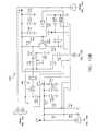
- FIG. 8A-8Ccollectively form an electrical schematic of an image sensor circuit of the camera assembly of FIG. 1 , according to one embodiment of the present invention.
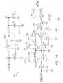
- FIG. 9A-9Dcollectively form an electrical schematic of the transmitter circuit of the camera assembly of FIG. 1 , according to one embodiment of the present invention.
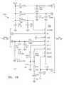
- FIG. 10A-10Dcollectively form an electrical schematic of a receiver circuit of the display device of FIG. 1 , according to one embodiment of the present invention.
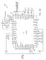
- FIG. 11is an electrical schematic for the CPU, the display, and power supply of the display device of FIG. 1 , according to one embodiment of the present invention.
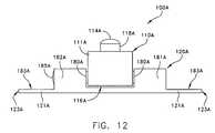
- FIG. 12is a schematic top view of a first alternative embodiment of an adjustable camera assembly that can be used in the backup camera system of FIG. 1 , wherein the camera is pivotally connected to the base.
- FIG. 13is a side view of the adjustable camera assembly of FIG. 12 .
- FIG. 14is a perspective view of the adjustable camera assembly of FIG. 12 wherein a portion of the base's housing is removed so that the interior mechanism for pivoting the camera is visible.
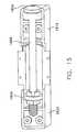
- FIG. 15is a perspective view of the adjustable camera assembly of FIG. 14 wherein the camera has been removed.
- FIG. 16is a top view of the interior pivoting mechanism of the adjustable camera assembly of FIG. 12 removed from the base.
- FIG. 17is a side schematic view of the adjustable camera assembly of FIG. 12 mounted to an exterior surface of a vehicle according one embodiment of the invention.
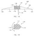
- FIG. 18is a top view of a second alternative embodiment of an adjustable camera assembly that can be used in the backup camera system of FIG. 1 , wherein the camera is pivotally connected to the base.
- FIG. 19schematically illustrates how the camera of the adjustable camera assembly if FIG. 19 can be pivoted.
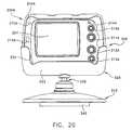
- FIG. 20is a front view of a first alternative embodiment of a multi-input display device that can be used in the backup camera system of FIG. 1 , according to one embodiment of the present invention.
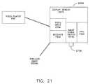
- FIG. 21is a high-level operational schematic of a backup camera system utilizing the multi-input display device of FIG. 20 in conjunction with a video player, according to another embodiment of the present invention.
- FIG. 22is a high-level operational schematic of a backup camera system utilizing the multi-input display device of FIG. 20 in conjunction with a video player connected to a modulator, according to another embodiment of the present invention.
- FIG. 23is a schematic of a combined wired-wireless backup camera system according to one embodiment of the present invention.
- FIG. 24is a high-level operational schematic of combined wired-wireless camera assembly according to one embodiment of the present invention.
- the backup camera system 1000generally comprises a camera assembly 100 , a display device 200 and a stand 300 .
- the backup camera system 1000is designed so that when the backup camera system 1000 is installed on a vehicle, the operator of the vehicle will be able to view a desired area adjacent the vehicle from the operator section of the passenger compartment. While the backup camera system 1000 and its installation will be described throughout this application in relation to viewing the area directly behind the vehicle, it is to be understood that the invention can be used to view any area adjacent the vehicle if desired.
- the backup camera system 1000is specifically designed for ease of installation by the end user. As such, it is preferred that the backup camera system 1000 be a retrofit kit for installation onto existing vehicle's that do not have a factory-installed backup camera system.
- the retrofit kitis to include, without limitation, the camera assembly 100 (or any of its alternative embodiments), the display device 200 (or any of its alternative embodiments), the stand 300 , a 12 volt cigarette lighter adaptor 400 for supplying power to the display device 200 (and/or a wiring harness for providing power to the display device 200 ), fasteners for mounting the camera assembly 200 to an exterior surface of a vehicle (such as license plate nuts and bolts and/or screws), a fastener for securing the stand 300 to a surface within a passenger compartment of a vehicle (such as a hook-and-loop fastener, a piece of double-sided tape, etc.), cable ties, Scotch-LokTM connectors, a video cable of sufficient length to facilitate the wired transmission of image signals from
- the retrofit kitmay not include all of the aforementioned components.
- the exact components included in any retrofit kitwill be dictated by the functional capabilities and structural particulars of the backup camera system 1000 to be provided and its intended installation.
- the camera assembly 100is a symmetric structure with respect to both its horizontal and vertical axes.
- the camera assembly 100comprises a camera portion 110 and a base portion 120 .
- the base portion 120is provided so that the camera assembly 100 can be mounted to the desired exterior surface of a vehicle. More specifically, the base portion 120 is adapted to be rigidly mounted to a vehicle using the vehicle's license plate mounting holes so that the camera portion 110 is facing rear of the vehicle so that objects behind the vehicle can be detected by the vehicle's operator, even when the objects are out of the operator's natural and/or mirror-assisted field of vision.
- the base portion 120comprises a pair of elongated flanges 121 that extend from the camera portion 110 in opposite directions. Stated another way, the flanges 121 extend in a lengthwise direction from the camera portion 110 at approximately 180° apart from one another.
- the flanges 121can be formed from a single elongated plate or from separate plates that assembled to one another and/or the camera portion 110 .
- Each flange 121comprises a hole 122 extending through its major face. Each of the holes 122 are spaced an approximately equal distance from the camera portion 110 and an approximately equal distance from the ends 123 of the flanges 121 .
- the holes 121are located and designed to be used to secure the camera assembly 100 to the vehicle using the vehicle's license plate mounting holes via fasteners 70 ( FIG. 6 ), such as bolts or screws. Specifically, the holes 121 are separated from one another by a linear distance that corresponds to the standard linear distance between the license plate mounting holes of vehicles, which is typically between 6-8 inches. The holes 121 are preferably oval shaped so as to provide a clearance in order to accommodate for differences that may exist between the license plate bolt holes of different vehicles. Of course, the holes 121 may have other geometric shapes depending upon the respective needs of the attachment devices and the hardware used.
- the camera portion 110is centrally located on the base portion 120 .
- the camera portion 110comprises a housing 111 that encloses and protects all of the necessary electrical components (including the camera 130 and transmitter 125 ) and internal circuitry to achieve the functions of the backup camera system 1000 discussed in this application.
- the internal circuitry and electrical components of the camera assembly 200are described in greater detail below in reference to FIGS. 7A , 8 and 9 .
- An opening 112is provided in a truncated cone structure 118 that protrudes from the front wall 113 of the housing 111 .
- the openingprovides a viewing passageway for the internally located camera 130 .
- the camera lens 114protrudes from and encloses the opening 112 .
- the camera lens 114is connected to the housing 111 so that a hermetic seal is formed between the lens 114 and the housing 111 , thereby hermetically sealing the opening 112 . This can be accomplished through the use of an appropriate gasket seal, O-ring, adhesion, a threaded fit, thermal welding, or other means known in the art.
- the lens 114has a vertical viewing angle of up to 80° and a horizontal viewing angle of 110°.
- the vertical viewing anglemay be up to 100° and the horizontal viewing angle may be up to 170°.
- the inventionis in no way limited by the viewing area of the lens utilized.
- the lens 114has an ultra-violet coating for light gathering and amplification. In some embodiments, it may be preferred that the lens 114 be provided with an additional layer of coating in order to prevent scratching from small accidents or other events. Alternatively, the entire lens 114 may be constructed out of materials such as plastics, or polycarbonate.
- the camera assembly 100further comprises a wire 115 that extends from an opening 117 in the rear wall 116 of the housing 111 .
- the wire 115comprises both the electrical power wires 140 that are to be connected to a power source of the vehicle and an external antenna cable 150 (or wire operably coupling an external transmitter to the camera 130 ).
- the opening 117 through which the wire 115 extendsis preferably heretically sealed through the use of a gasket, O-ring or other means.
- the wire 115can consist of multiple other cables.
- one or more female portscan be provided in the housing 111 and operably coupled to the internal circuitry as needed so that the power supply wires, antennas, video cables and other cables can be operably connected to the camera assembly 100 .
- the hermetic sealing of the housing 111keeps liquids away from the electrical circuitry and components of the camera assembly 100 , which will often be directly exposed directly to the harsh weather conditions during travel. As such, all possible openings into and out of the space within the housing 111 that holds moisture sensitive components should be sealed watertight, using a gasket seal, or some other type of mechanism that is able to prevent the entry of moisture.
- the space within the housing 111is preferably backfilled and pressurized with an inert gas, which may be a non-reactive gas, such as CO 2 , N 2 (nitrogen gas), or a noble gas such as helium, xenon, etc. in order to purge all moisture from the camera 111 and from the components of the transmitter 125 . Removal of the moisture from the housing 111 prevents the lens 114 from becoming clouded or fogged when it is exposed to the variable conditions of the environment.
- an inert gaswhich may be a non-reactive gas, such as CO 2 , N 2 (nitrogen gas), or
- the stand 300comprises a base structure 310 and support structure 320 .
- the support structure 320is pivotally connected to the base structure 310 via a swivel member 330 , which is in the form of a ball joint.
- the swivel member 330may be an axel-like pivot structure or any other type of pivoting joint.
- the support structure 320is a sleeve-like structure that is adapted to receive and support the display device 200 .
- the support structure 320comprises a rear wall 321 and a front wall 322 that forms a cavity 323 therebetween.
- An open top end of the support structure 320provides an opening through which the display device 200 can be slidably lowered into the cavity 323 .
- the cavity 323is sized and shaped to receive and accommodate the display device 200 , thereby supporting the display device 200 in an upright position for viewing (as shown in FIG. 2 ).
- the front wall 322 of the support structure 320comprises a cutout 324 .
- the cutout 324is sized, shaped and positioned so that when the display device 200 is positioned within the cavity 323 , the display screen 207 of the display device 200 is aligned with the cutout 324 so as to afford an unobstructed view of the display screen 220 and/or access to the controls 210 - 213 of the display device 200 .
- the support structure 320further comprises a notch 325 in one of its side walls.
- the notch 325is located on the support structure 320 so that when the display device 200 is positioned within the cavity 323 , the notch is aligned with and provides access to a female power supply port (not illustrated) located on a side surface of the display device 200 .
- a female power supply portnot illustrated
- the jack end of the 12 volt cigarette lighter adapter 400can be operably inserted into and removed from the display device 200 as desired without having to remove the display device 200 from the cavity 323 of the support structure 320 .
- one or more notches, cutout and/or openingmay be provided and suitably located on the support structure 320 so as to provide access to the ports and/or controls when the display device 200 is positioned within the cavity 323 .
- the support structure 320also comprises a securing means (not visible) that secures the display device 200 to the support structure 320 so that the display device 200 can not become accidentally separated and/or dislodged from the support structure 320 .
- the securing meanscan take on a wide variety of embodiments, such as a piece of double-sided tape located on either an inner surface of the cavity 323 of the support structure 320 or on the display device 200 , a male-female snap-lock system co-operationally positioned on the support structure 320 and the display device 200 , a hook-and-loop fastener system co-operationally positioned on the support structure 320 and the display device 200 , a tight-fit assembly between the support structure 320 and the display device 200 , a latching mechanism, a screw, a nut and bolt assembly, a threaded assembly, a strap, a band, etc.
- the relative size and shape of the cavity 323 of the support structure 320 with respect to the display device 200is designed to cradle the display device 200 in a manner that prevents dislodgment.
- the stand 300further comprises a securing means, generically illustrated as box element 340 , located on the bottom surface of the base structure 310 .
- the securing means 340is used to mount the stand 300 to an interior surface within the passenger compartment of the vehicle that is visible by the vehicle's operator, such as the dashboard surface.
- the securing means 340may be an adhesive material, such as double-sided tape, that is placed on the bottom surface of the support structure 320 so that the stand 310 .
- the securing means 340may be a hook-and-loop fastener tape wherein either the hook tape or the loop tape is attached to the dashboard and the other one of the hook tape or the loop tape is attached to the base structure 310 of the stand 300 . This permits the stand 300 to be easily placed and removed from the interior of the vehicle.
- the support structure 320is a sleeve-like structure, the invention is not so limited. In other embodiment, the support structure 320 can take on a wide variety shapes, sizes and structural arrangements so long as it capable of supporting the display device 200 .
- the stand 300 and the display device 200are placed in a location within the passenger compartment of the vehicle where the operator of the vehicle can see the display screen 207 , such as the dashboard
- the display device 200may be attached to the visors used in a vehicle, to the rear-view mirror, or to the windshield. When mounting the display device 200 directly to a visor or mirror it may not be necessary to use the stand 300 .
- the display device 200is a compact structure that is designed to be placed within a passenger compartment of a vehicle at a location visible by the operator of the vehicle.
- the display device 200comprises a housing 205 which acts as the main body of the display device 200 .
- the circuitry and electrical components that enable the operation, functioning and control of the display device 200are located within the housing 205 . Reference can be made to FIGS. 6 b , 9 and 10 , and the corresponding discussion, for more detailed information regarding the circuitry and electrical components of the display device 200 .
- the display device 200also comprises a display screen 207 for displaying images.
- the display screen 207is preferably sized in order to provide the operator of a vehicle with an adequate view of the images displayed on the display screen 207 .
- the display screen 207is roughly 2.5 inches when measured diagonally.
- the size of display screen 207is in no way limiting of the present invention and can be any size desired. The exact size of the display screen 207 will depend upon the size of the vehicle's interior space, the viewing needs of the operator of the vehicle and the target price of the retrofit kit.
- the display screen 207may be a thin film liquid crystal display, or alternatively some other type of display device that is capable of being able to produce an image.
- the display device 200further comprises a plurality of control buttons 210 - 213 .
- the control buttons 210 - 213are located on the front surface of the housing 205 adjacent the display screen 207 . Both the display screen and control buttons 210 - 213 are visible when the display screen is supported by the stand 300 .
- the control buttons 210 - 213are operably connected to the corresponding circuitry and/or electrical components of the display device 200 . As a result, the control buttons 210 - 213 control the various features and functions of the camera assembly 100 and/or the display device 200 .
- buttons 210 - 213any other type of control mechanisms can be utilized to operate and/or control the components of the backup camera system 1000 , including without limitation knobs, switches, slide switches, a touch screen, touch sensitive wheel, a remote control, a microphone for facilitating voice control, etc.
- control buttons on the display device 200include an increase brightness button 210 , a view adjust button 211 , a power button 212 and a decrease brightness button 213 .
- the buttons 210 - 213may be depressed to activate and/or deactivate the corresponding functionality.
- Depressing the increase brightness button 210increases the brightness of the display screen 207 .
- depressing the decrease brightness button 213decreases/lowers the brightness of the display screen 207 .
- the control features of the increase brightness button 210 and the decrease brightness button 213can be combined into a single control button.
- Depressing the view adjust button 211results in a rotation and/or inversion of the image displayed on the display screen as compared to how that image is perceived by the camera assembly 100 .
- the view adjust button 211(and its corresponding circuitry) is adapted to adjust and/or change the image displayed in the display screen 207 to be a forward image, a mirror image, a forward upside down image, a mirror upside down image, or some other alternative image type of the actual image perceived by the camera assembly 100 . Depressing the view adjust button 211 results in a cycling of the different image types being displayed on the display screen 207 .
- the view adjust button 211(and its corresponding circuitry) act as a switching mechanism that switches between displaying the images perceived by the different cameras assemblies of the backup camera system 1000 .
- the view adjust button 211(and its corresponding circuitry) can also act as a switching mechanism in embodiments where the display device 200 has multi-input capabilities (such as the embodiments of FIGS. 20-22 , which are discusses later in this application).
- a separate control button and/or control mechanismcan be used to manually cycle and/or switch between the different images and/or image types if desired.
- the power button 212turns the display device 200 on and off.
- the display device 200also includes a status light 214 that indicates whether or not the display device 200 is powered on or not.
- the status light 214is located on the front surface of the housing 205 so as to be visible from an operator section of the passenger compartment. It is to be understood that the display device 200 can have additional buttons, knobs and/or dials for controlling either the display device 200 or the camera assembly 100 as desired.
- certain functionscan be automated by programming the internal processor of the display device 200 to automatically perform certain functions upon detecting an event, such as the presence of a signal.
- an eventsuch as the presence of a signal.
- the display device 200so long as the display device 200 is operably coupled to a power source, the display device 200 (and thus the display screen 207 ) is automatically activated upon receipt of an image signal sent from the transmitter of the camera assembly 100 . Utilizing such automated activation of the display device 200 ensures that the operator of the vehicle has access to the visibility afforded by the backup camera system 1000 without being required to manually activate the display device 200 .
- the circuitry of the display device 200is designed so that the display device 200 (and thus the display screen 207 ) is automatically activated upon the starting the vehicle or when the car is placed into a certain gear, such as reverse.
- the backup camera system 1000further comprises a 12 volt power adapter 400 for supplying power to the display device 200 .
- the 12 volt power adapter 400is a flexible power wire 402 comprising a first end having a cigarette-lighter plug 401 and a second end having a standard male jack (not illustrated) for inserting into the female power supply port (not illustrated) of the display device 200 .
- the display device 10can be powered by batteries.
- the display device 200is powered by a power cable attached to the vehicle's fuse block. This setup enables the display device 200 to be automatically activated when the vehicle is turned on.
- the display device 200can be hardwired to the reverse light circuit of the vehicle. This setup enables the display device 200 to be automatically activated when the vehicle is placed into reverse and automatically deactivated when the vehicle is placed into a gear other than reverse.
- a wire 115extends from the rear wall 116 of the housing 111 (which holds the circuitry and electrical components of the camera assembly).
- the wire 115is actually a combination of multiple wires and antenna components. More specifically, the wire 115 comprises power supply wires 140 and an external antenna cable 150 .
- the external antenna cable 150runs adjacent to the power supply wires 140 .
- This adjacent relationship between the external antenna cable 150 and the power supply wires 140is achieved by encasing the external antenna cable 150 and the relevant portion of the power supply wires 140 with a piece of heat shrink tubing 160 (a portion of the external antenna cable 150 is shown removed from the heat shrink tubing 160 for illustrative purposes).
- a piece of heat shrink tubing 160a portion of the external antenna cable 150 is shown removed from the heat shrink tubing 160 for illustrative purposes.
- other equivalent structurescan be used to maintain the adjacent relationship between the external antenna cable 150 and the power supply wires 140 , including without limitation clasps, ties, bands, adhesion, string, thermal welding, clamps, etc. While maintaining the external antenna cable 150 adjacent to the power supply wires 140 is preferred, the external antenna cable 150 may not be so maintained in some embodiments.
- the power supply wires 140are of a sufficient length so that when the camera assembly 100 is mounted to an exterior surface of a rear portion of a vehicle, such as the license plate, the power supply wires 140 can be extended into the passenger compartment of the vehicle and operably connected to a power source, such as the reverse light circuit. In one embodiment, the power supply wires 140 are between 8 to 12 feet.
- the external antenna cable 150is of a sufficient length so that when the camera assembly 100 is mounted to an exterior surface of a rear portion of a vehicle, such as the license plate, the external antenna cable 150 also extends into the passenger compartment. In one embodiment, the external antenna cable 150 is between 8 to 16 inches in length.
- the passenger compartment of the vehicleincludes the trunk area, passenger area and operator area of the vehicle.
- the exemplified embodiment of the camera assembly 100 of FIG. 4utilizes power supply wires 140 for power
- other embodiments of the camera assemblymay 100 utilize an internal power supply, such as a battery, to supply the necessary power to the camera assembly 100 .
- the power supply of the camera assembly 100can be provided by a cable that operably attached to the display device 200 .
- Such a wirecan serve the dual function of signal transmission and power supply in hard-wired embodiments of the backup camera system 1000 .
- the external antenna cable 150comprises a coaxial cable 151 .
- a first end of the coaxial cable 151is operably coupled to the transmitter 125 ( FIG. 3D ) located within the housing 111 while a second end is adapted to act as an antenna.
- the second end of the coaxial cable 151comprises a ground plane housing 152 and an antenna portion 153 extending therefrom.
- the antenna portion 153wirelessly transmits the image signal that corresponds to image perceived by the camera 130 .
- a simple wiremay extend from the transmitter that acts as an antenna.
- the 2.4 GHz wireless image signal emitted from the transmitter 125does not have to penetrate the steel body of the vehicle and has to travel a reduced distance to the wireless signal receiver located within the display device 200 (which is positioned at a location viewable by the operator of the vehicle).
- the likelihood of the emitted wireless image signal arriving at the receiver with sufficient strength so as to yield a stable image on the display screen 207is increased. This is important because the output power of the transmitter 125 of the camera assembly 100 may not be increased above certain thresholds in the U.S. due to FCC regulations.
- the entire transmitteritself may be located externally of the housing 111 and operably coupled to the camera 130 via a flexible cable/wire.
- the transmittermay be located within a second housing that is located within the passenger compartment of the vehicle. As with the other embodiments, locating the entire transmitter inside the vehicle improves the signal strength and reduces interference from external devices.
- the camera assembly 100may be hard-wired directly to the display device rather than utilizing a wireless signal.
- the backup camera system 1000can be adapted to have both wired and wireless signal transmission capabilities.
- the positioners 40comprise a ring-like body 41 that forms an internal hole 42 .
- the hole 42is circular in shape and extends through the body 41 of the positioner 40 from the front surface 43 to the rear surface 44 .
- the inner surface of the positioner 40 that forms the hole 42may be sloped/tapered so as to assist in the proper orientation and guiding of a fastener (e.g., screw 70 ) through the hole 42 during the mounting process.
- positioner 40is exemplified as a generally circular ring-like structure, other shapes can be utilized, such as u-shape, rectangular, etc.
- the positioners 40can be made of any material, including without limitation flexible plastics, rubbers, metals, metal alloys, wood, etc. A flexible and/or resilient material is preferred but not necessary.
- the side view of the positioner 40 shown in FIG. 5Breveals that the positioner 40 is a tapered structure (with respect to its thickness).
- the tapered nature of the positioner 40is achieved by orienting the front and rear surfaces 44 , 43 at an acute angle ⁇ with respect to one another.
- the angle ⁇is preferably between 15-75°.
- the exact angle ⁇ to be usedwill depend on the specific needs of the vehicle to which the camera assembly 100 is to be mounted, such as the distance between the mounting location of the camera assembly 100 and the ground (e.g. the difference between the height of a sports utility vehicle and a sedan).
- the front surface 43slopes downward toward the rear surface 44 thereby forming a wedge-like structure.
- the tapered/wedge nature of the positioner 40allows the user to orient the camera assembly 130 at an angle ⁇ with respect to the surface of the vehicle to which the camera assembly 100 is mounted.
- the positioners 40allow the user to install the camera assembly 100 at a vertical angle that optimizes the viewing area for his/her specific vehicle.
- a plurality of sets of positioners 40 wherein each set has different angles ⁇may be provided so that the user can select a most optimal mounting angle for that specific vehicle.
- FIG. 6an embodiment of a procedure for mounting the camera assembly 100 to a rear portion 90 of a vehicle utilizing the positioners 40 will be described.
- four positioners 40 having the desired angle ⁇are selected.
- the camera assembly 100is then aligned with the desired mounting area on the vehicle, which in the illustration is over the license plate 95 . More specifically, the camera assembly 100 is aligned with the license plate 95 so that the holes 122 on the elongated flanges 120 of the camera assembly are aligned with the plate holes 96 .
- a first pair of positioners 40 Aare then positioned between license plate 95 and the camera assembly 100 so that the holes 42 A are aligned with the holes 96 and the flange holes 122 .
- the sloped surface 43 A of the positioners 40 Aface away from the vehicle and slope downward toward the vehicle.
- a second pair of positioners 40 Bare then position on the opposite side of the camera assembly 100 so that the holes 42 B are also aligned with the plate holes 96 , the holes 42 A and the flange holes 122 .
- the sloped surface 43 B of the positioners 40 Bface the vehicle and also slope downward toward the vehicle.
- Screws 70are then inserted through the holes 42 B of the second positioners 40 B, through the flange holes 122 of the camera assembly 100 , through the holes 42 A of the first positioners 40 A, through the plate holes 96 and into the license plate mounting holes 96 of the vehicle. Through threaded engagement, the camera assembly 100 is mounted to the rear portion 90 of the vehicle.
- the two pairs of positioners 40 A, 40 Bcooperate to not only orient the camera assembly 100 so that it is pointing downward in an angled manner from the vehicle but also give the head of the screws 70 a flush surface to which to engage.
- the angled mountingpermits the camera assembly to view at an optimal vertical angle.
- mounting the camera assembly 100is not limited to the method described above. Other means for mounting the camera assembly 100 to the vehicle may be used, such as adhesives, magnets, etc. It may also be possible to mount the camera assembly 100 so that the direction in which it points is controllable from the inside of the vehicle. This may be accomplished though the use of servo-motors or other devices operably attached to the interior of the camera assembly 100 so that it can adjust and orient the camera 130 .
- FIG. 7Aa high level schematic of the electronic components and circuitry of the camera assembly 100 is illustrated. As mentioned above, these electronic components and circuitry are located within the housing 111 in one embodiment of the instant invention.
- An image sensor 711is operably connected to the lens 114 .
- the image sensor 711converts light received through the lens 114 (which corresponds to a perceived image) into electrical impulses.
- the image sensor 711may be a CMOS, or some other appropriate sensor.
- the image sensor 711is operably coupled to an image signal processing circuit 722 .
- the image signal processing circuit 722takes the information (which is in the form of electrical impulses) received from the image sensor 711 and converts it into an image signal having a format that can be used by the display device 200 .
- Connected to the image signal processing circuitry 722is a transmitter 125 .
- the transmitter 125comprises a 8 Mhz crystal controlled oscillator 718 , a phased locked loop 716 and a phase array 714 .
- the a 8 Mhz crystal controlled oscillator 718 and the phased locked loop 716generate a 2.4 GHz RF signal based on the received image signal from the image signal processing unit 722 .
- This produced signalis then sent to the phase array 114 for isolation and amplification.
- the amplified signalis then sent to the antenna 153 , is tuned for 2.4 GHz, and wirelessly transmitted to the display device 200 . It is possible to transmit the signal at other frequencies if desired.
- the circuitry of the camera assembly 100also includes a switching power supply circuit 724 .
- the switching power supply circuit 724is provided for creating +3.3 V and +5V from the 12 volt DC energy from the vehicle. This provides power to the camera 130 .
- the poweris typically gathered through the power supply wires 140 , shown in FIG. 4 , which are attached to the wire that lights the reverse lights. This in turn activates the camera 130 and its circuitry when the vehicle is placed in reverse.
- the electrical components and circuitry of the display device 200perform a number of functions, including without limitation, transforming the wireless image signal received from the camera assembly 100 into an image displayed on the display screen 207 , powering the display device 200 , and executing user commands inputted via the controls 210 - 213 .
- the wireless transmitted image signalis received by the receiving antenna 746 and transmitted to the receiver 735 .
- the receiving antenna 146is tuned to 2.4 GHz. It should be understood that the receiving antenna 146 may be tuned to whatever frequency at which the image signal is transmitted.
- the circuitrycan be adapted to include a controller that automatically activates the display device 200 upon receipt and/or detection of a received image signal. Such automatic activation of the display device 200 eliminates the need for a separate action from the user, thereby ensuring that the area behind the vehicle is displayed on the display device at the necessary times.
- the receiver 735comprises a low noise amplifier (LNA) 744 , an 8 MHz crystal controlled oscillator 738 , a phase locked loop (PLL) 740 , a mixer 742 and an intermediate frequency amplifier 728 .
- the LNA 744boosts the 2.4 GHz signal that is received via the receiving antenna 746 .
- the 8 MHz crystal controlled oscillator 138 and the PLL 140generate a base frequency.
- the mixer 742is connected to the LNA 744 and the PLL 740 .
- the mixer 742combines the received 2.4 GHz signal and the base frequency to create an intermediate frequency (IF) signal.
- the IF signalis transmitted to the intermediate frequency amplifier 128 which increases the strength of the IF signal.
- the IF signalis then transmitted to a video demodulator 726 .
- the video demodulator 726strips away the IF and leaves only the image signal, which is then sent to an integrated circuit 732 .
- the integrated circuit 132is a thin film technology (TFT) driver circuit.
- the TFT driver circuit 132sets up and supplies the correct signals for the display screen 207 .
- the display screen 207shows the visual images associated with the image signals.
- the TFT driver circuit 132is connected to both the display screen 207 and the central processing unit (CPU) 723 .
- the CPU 723controls the receiver functions, uses image enhancement software, enables image rotation and/or inversion, and provides color.
- the CPU 723receives the signals generated from the operation of the controls 210 - 213 of the display device 200 and performs the appropriate action. For example, when the brightness is adjusted, or the image angle is to be switched, the CPU 723 receives the signal and acts upon it.
- Image rotation and inversionis provided so that in the event that the camera assembly 100 is mounted incorrectly, the image may be simply adjusted so that there is no need to remount the camera assembly 100 .
- the CPU 723is also connected to a switching power supply circuit 736 which creating the +3.3V, the +5V, the +12V, and the +14V from the 12 DC voltage provided by the vehicle from the adapter 400 .
- circuit 750that is used for the image sensor 711 and its associated components is illustrated.
- +12 Volt of direct currentis applied through a zener diode 751 that provides reverse polarity voltage protection for the camera 130 .
- the capacitors 752 - 753act as filters in the circuit 750 .
- a MOSFET transistor 754 and a voltage regulator 755form a current regulated +5 V DC regulator in the circuit 750 .
- An inductor 756 and capacitors 757 - 758filter the output that comes from the regulator formed by MOSFET transistor 754 and regulator 755 .
- Resistors 759 - 760establish a voltage reference for the regulator 755 .
- a sensor circuit 761 and its associated componentsconvert the light passing through the camera lens 114 into electrical impulses and determine the automatic gain control (AGC) levels and the video sync frequency for either PAL or NTSC formats.
- AGCautomatic gain control
- PALis used, however it is to be understood that other acceptable formats may be used.
- the composite video output of the sensor 761is then fed to the transmitter 125 .
- FIGS. 9A-9Da schematic of the circuit 770 that is used for the transmitter 125 and its associated components is illustrated.
- An image signal received from the image sensor 711is shown on the far left side of the circuit 770 .
- the composite image signalpasses through a series of filters that are composed of inductors 771 , capacitors 773 , and resistors 772 . These components operate together in order to form a bandpass filter that keeps unwanted frequencies from reaching the transmitter integrated circuit 775 .
- a voltage regulator 776 and its associated componentsconvert +5 VDC to +3.3 VDC for the integrated transmitter circuit 775 .
- the transmitter circuit 775is a 2.4 GHz audio/visual transmitter. In the embodiment shown in FIGS. 1 , 3 a - 3 d , and 4 only the visual section is used, however it is possible to utilize the audio section should one add a microphone to the camera assembly 100 .
- the oscillator 718( FIG. 7A ) is used by the transmitter circuit 775 to establish a frequency reference. This frequency is divided by the internal PLL 716 ( FIG. 7A ) into one of four frequencies: 2.414 GHz, 2.432 GHz, 2.450 GHz, 2.468 GHz. Control of the PLL 716 is determined by grounding combinations of inputs 777 to the transmitter circuit 775 .
- the 2.4 GHz RF output from the transmitter circuit 775passes through low pass, and bandpass filters consisting of the inductors 778 , the capacitors 779 , and a 3 pin Surface Acoustic Wave (SAW) filter 780 to the transmitter antenna 153 .
- the transmitter antenna 153is discussed in detail above with respect to FIG. 4 .
- the transmitter antenna 153may be a simple wire placed inside and/or outside of the camera housing 111 or it can be a 1 ⁇ 2wave dipole at the end of the coaxial cable 151 attached to the camera assembly 100 that permits the transmitter antenna 153 to be located inside the vehicle.
- FIGS. 10A-10Dconcurrently, a diagram of a circuit 500 for the 2.4 GHz receiver 735 ( FIG. 7B ) and its associated components is illustrated.
- the 2.4 GHz RF signalis picked up by the receiver antenna 746 , which may be a simple wire that is placed inside the housing 205 of the display device 200 .
- the transistors 511 and their associated componentsamplify the RF signal and feed it to the receiver circuit 515 .
- the receiver circuit 515is an integrated circuit.
- the receiver circuit 515 and its associated componentsform a complete RF receiver 735 in combination with the crystal oscillator 738 , the PLL 740 , and the IF amplifier 728 , automatic gain control, and video outputs 716 .
- the input pinsselect one of four frequencies, whichever is the same frequency as that used by the transmitter 125 .
- a voltage regulator 517regulates +5 V DC to +3.3 V DC.
- Video output from the receiver circuit 515is transmitted to the CPU 723 ( FIG. 7 ).
- FIG. 11a combined circuit 600 for the CPU 723 , the display screen 207 , and the power supply circuit 736 is illustrated.
- the values of the electrical componentshave been omitted.
- power for the display device 200is applied through the same type of circuit that the transmitter 125 uses, plus additional regulators and a DC-to-DC converter provide all the necessary voltages for the CPU 723 , the TFT driver IC 732 , and the display screen 207 .
- the TFT driver IC 732is located in the upper left section of the circuit 600 . Associated components provide power, brightness, contrast, and image rotate and inversion control functions to the display screen 207 .
- the CPU circuit 610is located in the upper right section of the circuit 600 . It accepts the image signal from the receiver 735 and provides image processing and color balance.
- the display circuit 611is located in the top center of the circuit 600 . It receives imaging data from the display circuit 611 of the CPU 723 , and control signals from the driver circuit 732 . The display circuit 611 turns the electrical impulses back into tiny pixels of light in the correct colors in order to recreate the image perceived by the camera 130 .
- FIGS. 12-17an alternative embodiment of a camera assembly 100 A that can be used in conjunction with the backup camera system 1000 of FIG. 1 is illustrated.
- the camera assembly 100 Acan replace and/or supplement the camera assembly 100 in the system and/or retrofit kit of the present invention.
- the camera assembly 100 Ais similar to the camera assembly 100 discussed above in relation to FIGS. 1-11 in many of its basic structural aspects and functioning. Thus the same reference characters will be used to identify like components of the camera assembly 100 A with the addition of alphabetical suffix “A.” In order to avoid redundancy, only those aspects of the camera assembly 100 A that differ from camera assembly 100 will be discussed in detail below.
- the camera assembly 100 Ais designed so that the camera portion 110 A can be pivoted relative to the base portion 120 A so that the viewing area of the lens 114 A can be adjusted as needed without having to remove the camera assembly 100 A from a vehicle once it is mounted.
- the camera assembly 100 Aalso eliminates the need to use the positioners 40 ( FIG. 6 ).
- the camera assembly 100 Agenerally comprises the base portion 120 A and the camera portion 110 A.
- the housing 111 of the camera portion 110 Ais pivotally connected to the base portion 120 A.
- the housing 111is pivotally connected to the base portion 120 A via a ratchet bar 180 A which provides an axis of rotation.
- the base portion 120 Acomprises first and second pivot flanges 181 A- 182 A that extend outward from the front surface 183 A of the elongated flanges 121 A.
- the pivot flanges 181 A- 182 Aare spaced from one another so as to provide a space therebetween in which the camera portion 110 A can be positioned.
- the pivot flanges 181 A- 182 Aare adapted to receive and support the ratchet bar 180 A in a manner that allows the ratchet bar 180 A to pivot about its axis.
- each of the pivot flanges 181 A- 182 Aalso forms a housing structure that accommodate one or more of the mechanisms discussed below, such as the rollback bar and gearing.
- the outer surface of the rear wall 116 Ais curved in a convex manner. In another embodiment, only the edges of the rear wall 116 A may need to beveled.
- the rear wall 116 Acan be flat.
- the pivot flanges 181 A- 182 Aare illustrated as housing structures, in other embodiments, the pivot flanges may be simple plate-like or other structures that accommodate the ends of the ratchet bar 180 A.
- the internal rotational mechanismscomprise the ratchet bar 180 A, an anti-rollback mechanism 183 A, and a ratchet member 184 A. These components co-operationally work with one another to facilitate the pivoting, locking and unlocking of the camera portion 110 A with respect to the base portion 120 A.
- the ratchet bar 180 Aextends through holed in the housing 111 A of the camera portion 110 A, which is rigidly attached thereto.
- the ratchet bar 180 Ais positioned within the pivot flanges 181 A- 182 A so as to be capable of being rotated about its axis.
- Connected near one end of the ratchet bar 180 Ais the ratchet member 184 A.
- the ratchet member 184 Acomprises tooth-like protrusions that co-operationally engage with the anti-rollback mechanism 183 A.
- the interaction between the ratchet member 184 A and the anti-rollback member 183 Apermit the ratcheting of the camera portion 110 A about the ratchet bar 180 A and can lock and unlock the camera portion 110 A in a desired pivoting position.
- An end cap 185 Ais connected to the other end of the ratchet bar 180 A and is accessible from outside of the pivot flange housings 181 A- 182 A.
- the end cap 185 Ais operably coupled to the internal mechanisms so that depressing the end cap 185 A releases the anti-rollback mechanism 183 A, thereby unlocking the ratchet bar 180 A and allowing the user to pivot the camera portion 110 A to the desired orientation.
- the anti-rollback mechanism 183 Aprohibits the ratchet bar 180 A from pivoting.
- FIG. 17the rotation of the camera portion 110 A of the camera assembly 100 A with respect to the base portion 120 A when mounted on a rear portion 90 of a vehicle will be discussed.
- the mounting procedure discussed above with respect to FIG. 6is generally applicable to the mounting of camera assembly 100 A except that the positioners 40 are not used.
- the camera assembly 100 Ais mounted over the license plate 50 using the license plate mounting holes via the elongated flanges 121 A.
- the base portion 120 Ais rigidly mounted to the rear portion 90 of the vehicle.
- the camera portion 110 Ais pivotally mounted to the base potion 120 A as described above, the camera portion 110 A can rotate about an axis, which in the illustration would be the z-axis (which is visible only as a point Z).
- the vertical direction in which the lens 114 is directedcan be rotated about the z-axis at an angle ⁇ .
- the angle ⁇may be between 0 and 180°, however it is preferred that angle ⁇ be between 0 and 90°.
- the axis about which the camera portion 110 A can pivot(which is the z-axis in the illustration) is preferably substantially horizontal and runs substantially parallel to a flat surface on which the vehicle is located. While the camera portion 110 A can only rotate about the z-axis in the exemplified embodiment, the invention is not so limited. In other embodiments, the camera portion 110 A may be pivotally mounted to the base portion 120 A so as to be able to rotate in a variety of directions with increased degrees of freedom. For example, a ball joint can be used as the pivot connection.
- the rotation/pivoting of the camera portionmay be controlled by the operator within the vehicle without having to manually pivot the camera portion. This can be achieved by including servo-motors in the camera assembly 100 A that are operable from within the vehicle. In such an embodiment, it may be possible to adapt the view adjust button 212 of the display device 200 to control the servo-motors.
- the camera assembly 100 Bcan replace and/or supplement the camera assemblies 100 , 100 A in the system and/or retrofit kit of the present invention.
- the camera assembly 100 Bis similar to the camera assemblies 100 , 100 A discussed above in relation in many of its basic structural aspects and functioning. Thus the same reference characters will be used to identify like components of the camera assembly 100 B with the addition of alphabetical suffix “B.” In order to avoid redundancy, only those aspects of the camera assembly 100 B that differ from camera assemblies 100 , 100 A will be discussed in detail below.
- the camera assembly 100 Bis designed so that the camera portion 110 B can be pivoted relative to the base portion 120 B so that the viewing area of the lens 114 B can be adjusted as needed without having to remove the camera assembly 100 B from a vehicle once it is mounted.
- the housing 111 B of the camera portion 110 Bis pivotally mounted to the base portion 120 B so that the front wall 113 B of the housing 34 is substantially flush with a front surface of the elongated flanges 121 B.
- the rear wall 116 B of the housing 111 Bhas a rounded surface that permits the housing 111 B in an unimpeded manner despite the existence of a very minimal clearance.
- An internal rotational mechanismsuch as that discussed above with respect to camera assembly 100 A, is used. However, as opposed to having some of the components of the internal rotational mechanism placed within the housing formed by the pivot flanges, the components of the internal rotational mechanism are placed within cavities formed within the elongated flanges 121 B themselves. Thus, the elongated flanges 121 B act as the pivot flanges in this embodiment. The placement of the internal rotational mechanism within the elongated flanges 38 and within the housing 111 B permits the camera assembly 100 B to have a low profile.
- FIG. 21an alternative embodiment of a multi-input display device 200 A that can be used in conjunction with the backup camera system 1000 of FIG. 1 is illustrated.
- the display device 200 Acan replace and/or supplement the display device 200 in the system and/or retrofit kit of the present invention.
- the display device 200 Ais similar to the display device 200 discussed above in relation to FIGS. 1-11 in many of its basic structural aspects, functioning and interaction with the other components of the backup camera system 1000 .
- the same reference characterswill be used to identify like components of the display device 200 A with the addition of alphabetical suffix “A.”
- alphabetical suffix “A”In order to avoid redundancy, only those aspects of the display device 200 A that differ from the display device 200 will be discussed in detail below.
- the display device 200 Acomprises a video input port 270 A and a manual switch 275 A provided on the front surface of the display housing 205 A.
- the video input port 270 A and the manual switch 275 Aare operably connected to the internal circuitry of the display device 200 A, as will be described later in relation to FIG. 21 .
- the video input port 270 Ais adapted to accommodate a first plug end of a video cable that is operably connected to an external video player 990 ( FIG. 21 ) at the other end.
- the video input port 270 Acan receive video signals from the external video player 990 for reproduction on the display screen 207 A. If desired, the video input port 270 A can also be adapted to operate as means for charging the external video player 990 .
- the video input port 270 Acan be any type of port that can be used to operably couple an external device, including without limitation a USB port, a standard jack port, a firewire port, an A/V port, a second RF receiver, etc.
- the manual switch 275 Ais operably connected to a switching circuit 970 A ( FIG. 21 ) that controls whether the image signal displayed on the display screen 207 A is based on the signal received from via the video input port 270 A or the receiver 735 A ( FIG. 21 ). Stated another way, the switching circuit 970 A is used to select between designating the video input port 270 A or the receiver 735 A as the image signal source for visual display on the display device 200 A. Of course, additional video sources can be incorporated into the display device 200 A. In the exemplified embodiment, the switch 275 A is a physical switch.
- the switch 275 Acan be an electronic switch such as a touch button on a the display screen 207 A, a voice recognition circuit, a touch wheel, a button, etc.
- the switching circuit 970 Aitself may be adapted to automatically select and/or switch the signal source upon detection of an event, thereby eliminating the need for a physical switch 275 A.
- a video player 990is operably coupled to the video input port 275 A via a video cable.
- the video player 990may be any type of video player, portable or installed in the vehicle, such as a DVD player or a video iPod®. It is intended that the video player 990 may be capable of reproducing and transmitting any type of video format such as MPEG-4, AVI, WMV-9, and DRM. It is further anticipated that additional formats may be employed as well.
- the multi-input display device 200 Ahas a receiver circuit 725 that is capable of receiving a wireless signal transmitted from a second image signal source, such as the camera assembly 100 . Both the video input port 275 A and the receiver circuit 735 A are operably coupled to the image signal switch 970 A.
- the image signal switch circuit 970 Ais operably connected to and controlled by the manual switch 275 A.
- the image signal switch 170is operably coupled to the CPU 723 A which performs the necessary image processing required to provide the image signals to the display screen 207 A for visual display.
- the image signal switch circuit 970 Aselects whether the visual display in the display screen 207 A is based on the image signal received from the video input port 275 A. Stated another way, depending on the position of the switch 275 A, the image signal switch circuit 970 A selects either the image signal from the video input port 275 A or the image signal from the receiver 735 A to transmit to the display screen 207 A.
- the image signal switch circuit 970 Ais exemplified as being controlled by the manual switch 275 A, the image signal switch 970 A may be designed to perform an automatic switching/selection upon the occurrence and/or detection of a certain event.
- the image signal switch 970 Acan automatically select transmission of the image signal from the video input port 275 A to the display screen 207 A upon a jack being inserted into the video input port 275 A or upon detecting an incoming video signal from the video input port 275 A.
- the receiver 735 Acan be deactivated when not selected as the signal source.
- the image signal switch 970 Acan be operated by the CPU 723 A so as to automatically switch/select transmission of the image signal received from the camera assembly 100 when the corresponding image signal is received at the receiver 735 A. This can occur, for example, when the camera assembly 100 and transmitter 125 are activated, such as when the vehicle is placed in reverse.
- FIG. 22an embodiment of the display device 200 A wherein its image signal switch 970 A (and corresponding circuitry) is adapted to select between processing one of a plurality of wireless signals for transmission to the display device 207 A is illustrated.
- the image signal from the video player 990 Awill be wireless, such as when the video player 990 A is connected directly to a video modulator 985 A.
- the video player 990 Amay contain an internal transmitter that enables direct transmission of video signals to the display device 200 A.
- the video player 990 Atransmits the video signal to the video modulator 985 A via a video cable.
- the video signalmay be transmitted through a USB port, or other compatible port such as a IEEE 1394 port (i.e. a firewire port).
- the video modulator 985 Amay also act as an inverter and operate to recharge the video player 990 A and/or supply power to it.
- the video modulator 985 Amay be plugged into a vehicle's 12 V socket and/or operate on batteries.
- the video modulator 985 Ahas a microprocessor 987 A that processes the image signals that are received from the video player 990 A.
- the microprocessor 987 Aprocesses the incoming image signals so that they can be transmitted to the display device 200 A. After the video modulator 985 A processes the image signals, they are transmitted to the modulator transmitter 986 A, where they are converted into wireless signals that are transmitted to the display device 200 A at a predetermined frequency which the receiver 735 A of the display device 200 A is enabled to receive.
- the image signal switch 970 Acan be adapted to detect the frequency of the incoming wireless signal received by the receiver 735 A. By detecting the frequency of the incoming image signal, the image signal switch 970 A can give priority (i.e., select for transmission) the image signal having a desired/pre-selected frequency. For example, the image signal switch 970 A can give priority to an incoming wireless image signal transmitted at the frequency at which the transmitter of the camera 100 transmits. Alternatively, the image signal from the camera 100 may contain data that instructs the CPU 723 A to activate the switch 970 A.
- the backup camera system 1000 Ccomprises a camera assembly 100 C, a display device 200 A, and a video cable 870 C.
- the backup camera system 1000 C, and its components,are similar to the backup camera system 1000 , and the components, discussed above in many aspects.
- the backup camera system 1000 Cis designed to facilitate both wired and wireless image signal transmission from the camera component 100 C to the display device 200 A.
- the display device 200 Ais described above with respect to FIGS. 20-22 .
- the video cable 870 Ccan be any type of cable capable of transmitting video signals, including without limitation a coaxial cable, a DSL cable, a phone cable, a USB cable, an A/V cable, etc.
- the ends of the video cable 870 Care adapted for operable insertion into and cooperation with the video out put port 889 C of the camera assembly 100 C and the video input port 270 A of the display device 200 A.
- the ends 871 C- 872 C of the video cable 870 Ccan be any type of adapter components, such as a USB jack, an A/V jack, a phone jack, a banana plug, etc.
- the camera assembly 100 Cis specifically designed to utilize the multi-input capabilities of the display device 200 A so that a user can choose whether the camera assembly 100 C is to transmit the image signal to the display device 100 C wirelessly or through a hard-wire connection.
- the backup camera system 1000 Cis especially useful in that a single kit can be used to afford viewing capabilities to a wide range of vehicles.
- the combined wire assembly 888 Ccomprises an external antenna cable 115 C identical to the one described above with respect to the FIG. 4 .
- the combined wire assembly 888 Calso comprises a video signal wire 877 C that is operably coupled to the internal circuitry of the camera assembly 100 C at one end and has the video output port 889 C at the other end.
- the video output port 889 Ccan be any type of port, including a USB port, a phone jack, a standard A/V port, etc.
- the video output port 889 Cis a 3.5 mm, 4 pole jack that is located within the interior of the vehicle when the camera assembly 100 C is mounted top the vehicle.
- the power supply wires 140 Ccan be incorporated into the same heat shrink tubing 160 C which surrounds the external antenna cable 150 C and the video signal wire 877 C, as is schematically shown in FIG. 24 and described with respect to FIG. 4 above.
- the display device 200 Afunctions as discussed above in FIGS. 21-22 , including the functions associated with the switching circuit 970 A.
- the internal circuitry of the camera assembly 100 Cis designed to perform a similar switching function with respect to transmission of the image signal.
- the camera assembly 100 Ccomprises an image signal switch circuit 878 C operably coupled to the image signal processor 722 C, the transmitter 125 C and the video output port 877 C.
- the image signal switching circuit 878 Creceives the image signal (which corresponds to the perceived image) from the image signal processor 722 C.
- the image signal switching circuit 878 Cselects whether the image signal will be transmitted to the transmitter 125 C for wireless transmission to the display device 200 A or to the video output port 889 C for hard-wired transmission to the display device 200 A.
- the selection by the image signal switching circuit 878 Ccan be dictated by a manual switch or can be automated.
- the image signal switching circuit 878 Ceither transmits the image signal to the video output port 889 C or to the transmitter 125 C.
- the selection of the image signal switching circuit 878 Cis dictated by the occurrence and/or detection of a certain event.
- the image signal switching circuit 878 Ccan automatically select transmission of the image signal to the video output port 889 C upon the plug 871 C of the video cable 870 C being inserted into the video output port 889 C.
- the transmitter 125 Ccan be deactivated when not selected as the transmission source.
- the camera assembly 100 Cmay then send both power and the video signal to the display device 200 A.
Landscapes
- Engineering & Computer Science (AREA)
- Mechanical Engineering (AREA)
- Chemical & Material Sciences (AREA)
- Combustion & Propulsion (AREA)
- Transportation (AREA)
- Multimedia (AREA)
- Fittings On The Vehicle Exterior For Carrying Loads, And Devices For Holding Or Mounting Articles (AREA)
- Closed-Circuit Television Systems (AREA)
- Studio Devices (AREA)
Abstract
Description
Claims (45)
Priority Applications (4)
| Application Number | Priority Date | Filing Date | Title |
|---|---|---|---|
| US11/854,815US8194132B2 (en) | 2006-01-20 | 2007-09-13 | System for monitoring an area adjacent a vehicle |
| US13/462,371US20130033599A1 (en) | 2006-01-20 | 2012-05-02 | System for monitoring an area adjacent a vehicle |
| US14/725,609US9637051B2 (en) | 2006-01-20 | 2015-05-29 | System for monitoring an area adjacent a vehicle |
| US15/894,569US11603042B2 (en) | 2006-01-20 | 2018-02-12 | System for monitoring an area adjacent a vehicle |
Applications Claiming Priority (12)
| Application Number | Priority Date | Filing Date | Title |
|---|---|---|---|
| US29/252,296USD536011S1 (en) | 2006-01-20 | 2006-01-20 | System for monitoring an area behind a vehicle |
| US29/252,239USD536360S1 (en) | 2006-01-20 | 2006-01-20 | Video monitor and stand |
| US29/252,238USD535676S1 (en) | 2006-01-20 | 2006-01-20 | Mountable camera |
| US29/258,861USD536016S1 (en) | 2006-04-28 | 2006-04-28 | Monitor and holder for camera devices |
| US29/258,863USD536012S1 (en) | 2006-04-28 | 2006-04-28 | Back-up camera |
| US82661806P | 2006-09-22 | 2006-09-22 | |
| US11/567,504US7245207B1 (en) | 2006-01-20 | 2006-12-06 | Camera and display device for use with vehicles |
| US88268106P | 2006-12-29 | 2006-12-29 | |
| US88963107P | 2007-02-13 | 2007-02-13 | |
| US94975907P | 2007-07-13 | 2007-07-13 | |
| US77833907A | 2007-07-16 | 2007-07-16 | |
| US11/854,815US8194132B2 (en) | 2006-01-20 | 2007-09-13 | System for monitoring an area adjacent a vehicle |
Related Parent Applications (1)
| Application Number | Title | Priority Date | Filing Date |
|---|---|---|---|
| US77833907AContinuation-In-Part | 2006-01-20 | 2007-07-16 |
Related Child Applications (2)
| Application Number | Title | Priority Date | Filing Date |
|---|---|---|---|
| US29/303,462ContinuationUSD577050S1 (en) | 2006-01-20 | 2008-02-08 | Mountable camera |
| US13/462,371ContinuationUS20130033599A1 (en) | 2006-01-20 | 2012-05-02 | System for monitoring an area adjacent a vehicle |
Publications (2)
| Publication Number | Publication Date |
|---|---|
| US20080030311A1 US20080030311A1 (en) | 2008-02-07 |
| US8194132B2true US8194132B2 (en) | 2012-06-05 |
Family
ID=39028569
Family Applications (4)
| Application Number | Title | Priority Date | Filing Date |
|---|---|---|---|
| US11/854,815Active2029-05-01US8194132B2 (en) | 2006-01-20 | 2007-09-13 | System for monitoring an area adjacent a vehicle |
| US13/462,371AbandonedUS20130033599A1 (en) | 2006-01-20 | 2012-05-02 | System for monitoring an area adjacent a vehicle |
| US14/725,609ActiveUS9637051B2 (en) | 2006-01-20 | 2015-05-29 | System for monitoring an area adjacent a vehicle |
| US15/894,569Active2027-08-31US11603042B2 (en) | 2006-01-20 | 2018-02-12 | System for monitoring an area adjacent a vehicle |
Family Applications After (3)
| Application Number | Title | Priority Date | Filing Date |
|---|---|---|---|
| US13/462,371AbandonedUS20130033599A1 (en) | 2006-01-20 | 2012-05-02 | System for monitoring an area adjacent a vehicle |
| US14/725,609ActiveUS9637051B2 (en) | 2006-01-20 | 2015-05-29 | System for monitoring an area adjacent a vehicle |
| US15/894,569Active2027-08-31US11603042B2 (en) | 2006-01-20 | 2018-02-12 | System for monitoring an area adjacent a vehicle |
Country Status (1)
| Country | Link |
|---|---|
| US (4) | US8194132B2 (en) |
Cited By (31)
| Publication number | Priority date | Publication date | Assignee | Title |
|---|---|---|---|---|
| US20110013020A1 (en)* | 2008-04-21 | 2011-01-20 | Si-Rae Jo | Wireless transmitting and receiving apparatus for vehicle rear and side views independent of the vehicle's body and method thereof |
| US20130038731A1 (en)* | 2011-08-09 | 2013-02-14 | Continental Automotive Systems, Inc. | Moveable backup camera |
| US8379289B2 (en) | 2003-10-02 | 2013-02-19 | Donnelly Corporation | Rearview mirror assembly for vehicle |
| US8400704B2 (en) | 2002-09-20 | 2013-03-19 | Donnelly Corporation | Interior rearview mirror system for a vehicle |
| US8465163B2 (en) | 2002-06-06 | 2013-06-18 | Donnelly Corporation | Interior rearview mirror system |
| US8465162B2 (en) | 2002-06-06 | 2013-06-18 | Donnelly Corporation | Vehicular interior rearview mirror system |
| US8503062B2 (en) | 2005-05-16 | 2013-08-06 | Donnelly Corporation | Rearview mirror element assembly for vehicle |
| US8508383B2 (en) | 2008-03-31 | 2013-08-13 | Magna Mirrors of America, Inc | Interior rearview mirror system |
| US20130242099A1 (en)* | 2012-03-06 | 2013-09-19 | Magna Electronics Inc. | Vehicle camera with tolerance compensating connector |
| US8543330B2 (en) | 2000-03-02 | 2013-09-24 | Donnelly Corporation | Driver assist system for vehicle |
| US20130258077A1 (en)* | 2012-03-16 | 2013-10-03 | Magna Electronics, Inc. | Video output diagnostics for automotive application |
| US8559093B2 (en) | 1995-04-27 | 2013-10-15 | Donnelly Corporation | Electrochromic mirror reflective element for vehicular rearview mirror assembly |
| US8577549B2 (en) | 2003-10-14 | 2013-11-05 | Donnelly Corporation | Information display system for a vehicle |
| US8610992B2 (en) | 1997-08-25 | 2013-12-17 | Donnelly Corporation | Variable transmission window |
| USD702235S1 (en)* | 2012-02-23 | 2014-04-08 | Wacom Co., Ltd. | Coordinate input display device |
| US8797627B2 (en) | 2002-09-20 | 2014-08-05 | Donnelly Corporation | Exterior rearview mirror assembly |
| US8884788B2 (en) | 1998-04-08 | 2014-11-11 | Donnelly Corporation | Automotive communication system |
| US8908039B2 (en) | 2000-03-02 | 2014-12-09 | Donnelly Corporation | Vehicular video mirror system |
| US9233641B2 (en) | 2011-02-25 | 2016-01-12 | Magna Electronics Inc. | Vehicular camera with aligned housing members and electrical connection between aligned housing members |
| US9278654B2 (en) | 1999-11-24 | 2016-03-08 | Donnelly Corporation | Interior rearview mirror system for vehicle |
| US9376061B2 (en) | 1999-11-24 | 2016-06-28 | Donnelly Corporation | Accessory system of a vehicle |
| US9656690B2 (en) | 2012-10-30 | 2017-05-23 | Robert Bosch Gmbh | System and method for using gestures in autonomous parking |
| WO2017177302A1 (en)* | 2016-04-15 | 2017-10-19 | Light Wave Technology Inc. | Automotive rear-view camera peripheral |
| US9809171B2 (en) | 2000-03-02 | 2017-11-07 | Magna Electronics Inc. | Vision system for vehicle |
| USD807939S1 (en)* | 2016-05-23 | 2018-01-16 | Evoko Unlimited AB | Accessory for a camera lens |
| USD836511S1 (en)* | 2017-12-19 | 2018-12-25 | Rydeen North America, Inc. | Bracket |
| US10295666B2 (en)* | 2014-10-03 | 2019-05-21 | Panasonic Intellectual Property Management Co., Ltd. | Object detection device |
| USD853292S1 (en)* | 2017-12-19 | 2019-07-09 | Rydeen North America, Inc. | Bar |
| US10606367B2 (en) | 2016-07-11 | 2020-03-31 | Light Wave Technology Inc. | Command relay device, system and method for providing remote assistance/remote control |
| US10857941B2 (en)* | 2019-01-28 | 2020-12-08 | Toyota Motor Engineering & Manufacturing North America, Inc. | E-mirror automatic position adjustment system |
| US11208054B2 (en) | 2020-03-18 | 2021-12-28 | Toyota Motor Engineering & Manufacturing North America, Inc. | Quick release rear view camera system |
Families Citing this family (41)
| Publication number | Priority date | Publication date | Assignee | Title |
|---|---|---|---|---|
| US5668663A (en) | 1994-05-05 | 1997-09-16 | Donnelly Corporation | Electrochromic mirrors and devices |
| US6891563B2 (en)* | 1996-05-22 | 2005-05-10 | Donnelly Corporation | Vehicular vision system |
| US6124886A (en) | 1997-08-25 | 2000-09-26 | Donnelly Corporation | Modular rearview mirror assembly |
| US6326613B1 (en)* | 1998-01-07 | 2001-12-04 | Donnelly Corporation | Vehicle interior mirror assembly adapted for containing a rain sensor |
| US6172613B1 (en)* | 1998-02-18 | 2001-01-09 | Donnelly Corporation | Rearview mirror assembly incorporating vehicle information display |
| US8288711B2 (en) | 1998-01-07 | 2012-10-16 | Donnelly Corporation | Interior rearview mirror system with forwardly-viewing camera and a control |
| US6445287B1 (en) | 2000-02-28 | 2002-09-03 | Donnelly Corporation | Tire inflation assistance monitoring system |
| AU2001243285A1 (en) | 2000-03-02 | 2001-09-12 | Donnelly Corporation | Video mirror systems incorporating an accessory module |
| US7255451B2 (en) | 2002-09-20 | 2007-08-14 | Donnelly Corporation | Electro-optic mirror cell |
| US7581859B2 (en) | 2005-09-14 | 2009-09-01 | Donnelly Corp. | Display device for exterior rearview mirror |
| AU2002251807A1 (en) | 2001-01-23 | 2002-08-19 | Donnelly Corporation | Improved vehicular lighting system for a mirror assembly |
| US6918674B2 (en) | 2002-05-03 | 2005-07-19 | Donnelly Corporation | Vehicle rearview mirror system |
| TWM284569U (en)* | 2005-10-12 | 2006-01-01 | Cing-Liang Lyu | Wide-angle rearview mirror assembly for rearview and car-backing monitoring |
| JP4286294B2 (en)* | 2007-02-21 | 2009-06-24 | 三洋電機株式会社 | Driving support system |
| US20090096870A1 (en)* | 2007-10-10 | 2009-04-16 | Edward Zheng | GPS with back up camera |
| US20120154589A1 (en)* | 2009-09-11 | 2012-06-21 | Aisin Seiki Kabushiki Kaisha | Vehicle surrounding monitor apparatus |
| JP4985745B2 (en)* | 2009-10-30 | 2012-07-25 | 株式会社デンソー | Perimeter monitoring system for moving objects |
| US20120069218A1 (en)* | 2010-09-20 | 2012-03-22 | Qualcomm Incorporated | Virtual video capture device |
| US9164500B2 (en)* | 2011-01-11 | 2015-10-20 | Buffalo Filter Llc | Method and device for remote control of an apparatus |
| US9058706B2 (en)* | 2012-04-30 | 2015-06-16 | Convoy Technologies Llc | Motor vehicle camera and monitoring system |
| CN103076095B (en)* | 2012-12-11 | 2015-09-09 | 广州飒特红外股份有限公司 | A kind of with the motor-driven carrier nighttime driving backup system of panel computer wireless operated thermal infrared imager |
| US9282294B2 (en)* | 2012-12-19 | 2016-03-08 | 2236008 Ontario, Inc. | Integrated system for media playback during startup |
| US20150172518A1 (en)* | 2013-12-13 | 2015-06-18 | Convoy Technologies, LLC, | Monitoring system and method including selectively mountable wireless camera |
| US9718405B1 (en) | 2015-03-23 | 2017-08-01 | Rosco, Inc. | Collision avoidance and/or pedestrian detection system |
| US20170080861A1 (en)* | 2015-05-04 | 2017-03-23 | Pearl Automation Inc. | Vehicle sensor system and method of use |
| WO2017044576A1 (en)* | 2015-09-08 | 2017-03-16 | Pearl Automation Inc. | Vehicle sensor system and method of use |
| US11285878B2 (en)* | 2015-12-17 | 2022-03-29 | Magna Electronics Inc. | Vehicle vision system with camera line power filter |
| TWI656692B (en)* | 2015-12-31 | 2019-04-11 | 鴻海精密工業股份有限公司 | Communication device |
| US10300843B2 (en)* | 2016-01-12 | 2019-05-28 | Ford Global Technologies, Llc | Vehicle illumination assembly |
| KR102310718B1 (en) | 2017-03-20 | 2021-10-08 | 삼성전자주식회사 | Convertible stand of display apparatus |
| JP6850659B2 (en)* | 2017-03-31 | 2021-03-31 | ルネサスエレクトロニクス株式会社 | Manufacturing method of semiconductor devices |
| CN106945522A (en)* | 2017-04-11 | 2017-07-14 | 吉林省德科电子有限公司 | The automobile instrument with log based on bus communication |
| USD822581S1 (en)* | 2017-05-16 | 2018-07-10 | Spigen Korea Co., Ltd. | Electronic device mount for vehicles |
| USD822582S1 (en)* | 2017-05-16 | 2018-07-10 | Spigen Korea Co., Ltd. | Electronic device mount for vehicles |
| USD821290S1 (en)* | 2017-05-17 | 2018-06-26 | Spigen Korea Co., Ltd. | Electronic device mount for vehicles |
| USD821291S1 (en)* | 2017-07-17 | 2018-06-26 | Spigen Korea Co., Ltd. | Electronic device mount for vehicles |
| US10924685B2 (en)* | 2018-05-07 | 2021-02-16 | Rubicon Products, LLC | Night vision apparatus |
| CN208956166U (en)* | 2018-11-01 | 2019-06-07 | 华为技术有限公司 | A kind of picture pick-up device |
| US11272144B2 (en) | 2020-01-15 | 2022-03-08 | George Gorgees | Large vehicle backup camera apparatus |
| CN112950983A (en)* | 2021-01-29 | 2021-06-11 | 陕西建工安装集团有限公司 | Parking lot vehicle positioning method and system |
| US12115916B2 (en) | 2021-02-01 | 2024-10-15 | Rosco, Inc. | Downlighting signal and illumination mirror head for vehicle |
Citations (262)
| Publication number | Priority date | Publication date | Assignee | Title |
|---|---|---|---|---|
| US3442191A (en) | 1966-05-27 | 1969-05-06 | Eastman Kodak Co | Optical means for controlling acceptance angle of a photoresponsive device |
| US3868743A (en) | 1972-04-19 | 1975-03-04 | Nissan Motor | Wiper assembly for a motor driven vehicles |
| US4113137A (en) | 1977-09-21 | 1978-09-12 | Cohu, Inc. | Camera housing optical sealing method and device |
| US4214266A (en) | 1978-06-19 | 1980-07-22 | Myers Charles H | Rear viewing system for vehicles |
| US4262383A (en) | 1978-08-12 | 1981-04-21 | Regie Nationale Des Usines Renault | Window-wiping device for double headlights on motor vehicles |
| US4277804A (en) | 1978-11-01 | 1981-07-07 | Elburn Robison | System for viewing the area rearwardly of a vehicle |
| US4420238A (en) | 1982-04-19 | 1983-12-13 | Felix Larry L | Apparatus for enabling concealing surveillance by use of a camera in a vehicle |
| US4504861A (en) | 1982-02-18 | 1985-03-12 | Emcee A Division Of Electronics, Missiles & Communications, Inc. | Portable TV transmitter |
| US4517565A (en) | 1981-08-21 | 1985-05-14 | Honda Giken Kogyo Kabushiki Kaisha | Apparatus for visually indicating the current location of an automotive vehicle |
| US4532544A (en) | 1983-06-28 | 1985-07-30 | Gregor Federau | Line-scan panoramic camera |
| US4789904A (en) | 1987-02-13 | 1988-12-06 | Peterson Roger D | Vehicle mounted surveillance and videotaping system |
| US4895326A (en) | 1988-05-27 | 1990-01-23 | Scosche Industries, Inc. | In-dash installation kit adaptable to different radios and different dash configurations |
| US4910591A (en) | 1988-08-08 | 1990-03-20 | Edward Petrossian | Side and rear viewing apparatus for motor vehicles |
| US4993913A (en) | 1988-07-15 | 1991-02-19 | Nihon Biso Kabushiki Kaisha | Robot for a work on a wall surface |
| US5027200A (en) | 1990-07-10 | 1991-06-25 | Edward Petrossian | Enhanced viewing at side and rear of motor vehicles |
| US5056903A (en) | 1988-03-31 | 1991-10-15 | Minolta Camera Kabushiki Kaisha | Lens barrel structure for waterproof camera |
| US5056902A (en) | 1990-04-25 | 1991-10-15 | Smith & Nephew Dyonics, Inc. | Magnetically coupled lens actuator |
| US5077567A (en) | 1990-08-20 | 1991-12-31 | Asahi Kogaku Kogyo Kabushiki Kaisha | Water-sealed camera |
| US5107286A (en) | 1990-09-24 | 1992-04-21 | Burle Technologies, Inc. | Environmentally sealed camera housing |
| US5111289A (en) | 1990-04-27 | 1992-05-05 | Lucas Gary L | Vehicular mounted surveillance and recording system |
| US5113290A (en) | 1990-12-13 | 1992-05-12 | Honeywell Inc. | Sealed focusing assembly for an industrial vision system |
| US5260731A (en) | 1992-01-13 | 1993-11-09 | Baker Jr Roy E | Camera mount for a vehicle |
| US5264962A (en) | 1991-08-22 | 1993-11-23 | Kho Myung D | Sideview mirror for vehicles |
| US5289321A (en) | 1993-02-12 | 1994-02-22 | Secor James O | Consolidated rear view camera and display system for motor vehicle |
| US5289091A (en) | 1991-09-09 | 1994-02-22 | Matsushita Electric Industrial Co., Ltd. | Apparatus for turning monitoring camera |
| US5355818A (en) | 1992-08-27 | 1994-10-18 | Strait Imaging Research | Portable inspection equipment for ocean going vessels |
| US5410346A (en) | 1992-03-23 | 1995-04-25 | Fuji Jukogyo Kabushiki Kaisha | System for monitoring condition outside vehicle using imaged picture by a plurality of television cameras |
| US5455625A (en) | 1993-09-23 | 1995-10-03 | Rosco Inc. | Video camera unit, protective enclosure and power circuit for same, particularly for use in vehicles |
| US5467264A (en) | 1993-06-30 | 1995-11-14 | Microsoft | Method and system for selectively interdependent control of devices |
| US5475494A (en) | 1992-12-22 | 1995-12-12 | Mitsubishi Denki Kabushiki Kaisha | Driving environment surveillance apparatus |
| US5529271A (en) | 1994-12-20 | 1996-06-25 | Dunchock; Richard | Reversible mount for a telephone |
| US5550677A (en) | 1993-02-26 | 1996-08-27 | Donnelly Corporation | Automatic rearview mirror system using a photosensor array |
| USD373580S (en) | 1994-09-07 | 1996-09-10 | International Business Machines Corporation | Display unit with an attachable camera unit |
| US5574426A (en) | 1995-06-30 | 1996-11-12 | Insys, Ltd. | Obstacle detection system for vehicles moving in reverse |
| US5574443A (en) | 1994-06-22 | 1996-11-12 | Hsieh; Chi-Sheng | Vehicle monitoring apparatus with broadly and reliably rearward viewing |
| USD376146S (en) | 1995-02-21 | 1996-12-03 | Totsch John W | Body worn video camera transmitter housing |
| US5594498A (en) | 1994-10-14 | 1997-01-14 | Semco, Inc. | Personal audio/video surveillance system |
| US5596228A (en) | 1994-03-10 | 1997-01-21 | Oec Medical Systems, Inc. | Apparatus for cooling charge coupled device imaging systems |
| USD378095S (en) | 1994-09-26 | 1997-02-18 | Elmo Company Limited | Surveillance camera |
| US5612686A (en) | 1993-09-28 | 1997-03-18 | Hitachi, Ltd. | Method and an apparatus for monitoring the environment around a vehicle and an operation support system using the same |
| US5642238A (en) | 1995-01-30 | 1997-06-24 | Mbs Foundry Inc. | Ergonomically efficient side and rear vision system for motor vehicles |
| US5648835A (en) | 1992-09-22 | 1997-07-15 | Olympus Optical Co., Ltd. | Optical system for monitor cameras to be mounted on vehicles |
| US5670935A (en) | 1993-02-26 | 1997-09-23 | Donnelly Corporation | Rearview vision system for vehicle including panoramic view |
| US5677667A (en) | 1995-02-23 | 1997-10-14 | Vehicle Enhancement Systems, Inc. | Data communications apparatus for tractor/trailer using pneumatic coupler |
| US5680123A (en) | 1996-08-06 | 1997-10-21 | Lee; Gul Nam | Vehicle monitoring system |
| USD388107S (en) | 1996-08-06 | 1997-12-23 | Huckins Terry D | Combined camera and mount system for a vehicle |
| USD388450S (en) | 1996-02-07 | 1997-12-30 | Star Micronics Co., Ltd. | Monitor camera |
| US5725189A (en) | 1996-06-05 | 1998-03-10 | Qs Holding Company | Media mounting device for motor vehicles |
| US5729016A (en) | 1994-04-12 | 1998-03-17 | Hughes Aircraft Company | Low cost night vision system for nonmilitary surface vehicles |
| US5738322A (en) | 1995-10-06 | 1998-04-14 | Huang; Tzu-Ping | Mounting frame for articles rack in the car |
| US5760828A (en) | 1994-06-03 | 1998-06-02 | Idesa Accesorios, S.A. | Back-vision system for vehicles |
| US5793308A (en) | 1992-07-02 | 1998-08-11 | Sensorvision Technologies, L.L.C. | Vehicular position monitoring system with integral mirror video display |
| US5793300A (en) | 1993-03-15 | 1998-08-11 | Prince Corporation | Trainable RF receiver for remotely controlling household appliances |
| US5835808A (en) | 1997-12-22 | 1998-11-10 | Parker; Peter W. | Vehicular camera mount |
| US5848299A (en) | 1997-12-05 | 1998-12-08 | Shepper; John | Integumentary enclosure for video equipment |
| US5852754A (en) | 1997-08-27 | 1998-12-22 | Videolarm, Inc. | Pressurized housing for surveillance camera |
| GB2327823A (en) | 1997-07-30 | 1999-02-03 | Nigel Geoffrey Ley | Rear-view viewing system |
| US5947440A (en) | 1996-11-06 | 1999-09-07 | Samsung Electronics Co., Ltd. | Flat-panel display apparatus |
| US5956527A (en) | 1998-05-05 | 1999-09-21 | Eastman Kodak Company | Waterproof protective housing for camera |
| US5959555A (en) | 1996-08-23 | 1999-09-28 | Furuta; Yoshihisa | Apparatus for checking blind spots of vehicle |
| US6025784A (en) | 1998-02-12 | 2000-02-15 | Micron Technology, Inc. | Vehicles, license plate frame assemblies, methods of forming license plate frames, and methods of attaching RFIDs, transponders and modulators to vehicles |
| US6025872A (en) | 1996-09-09 | 2000-02-15 | Yazaki Corporation | Monitor region extension member and motor vehicle peripheral monitoring apparatus using same |
| GB2341028A (en) | 1998-08-19 | 2000-03-01 | Tseng Chun Jung | Vehicle mounted camera array and monitor for driver blind-spot imaging |
| US6036070A (en) | 1998-08-05 | 2000-03-14 | Gauthier; Diane Blais | Vehicular cargo carrier and support attachment therefor |
| DE19841915A1 (en) | 1998-09-14 | 2000-03-16 | Bosch Gmbh Robert | Electronically assisted reverse drive system |
| JP2000134516A (en) | 1998-10-26 | 2000-05-12 | Sony Corp | Electronic camera device for peripheral confirmation and vehicle equipped with the same device |
| USD425558S (en) | 1998-09-18 | 2000-05-23 | Nuvomedia, Inc. | Electronic book |
| US6078344A (en) | 1997-09-11 | 2000-06-20 | Eastman Kodak Company | Resistive thermal printing apparatus and method having a non-contact heater |
| US6078355A (en) | 1996-10-25 | 2000-06-20 | Zengel; John A. | Vehicle periphery monitoring system |
| JP2000175182A (en) | 1998-12-03 | 2000-06-23 | Sony Corp | On-vehicle monitoring camera system |
| US6091453A (en) | 1996-07-29 | 2000-07-18 | Coan; Steven | Hand held remote camera |
| US6100921A (en) | 1998-05-11 | 2000-08-08 | Rowley; Steven R. | Thru-hull video camera |
| US6111498A (en) | 1997-12-09 | 2000-08-29 | Sawtooth Embedded Systems | Trip computer read-out on rearview camera screen |
| US6122597A (en) | 1997-04-04 | 2000-09-19 | Fuji Jukogyo Kabushiki Kaisha | Vehicle monitoring apparatus |
| US6126125A (en) | 1998-01-13 | 2000-10-03 | Ncr Corporation | Electronic price label mounting device |
| US6130706A (en) | 1998-03-25 | 2000-10-10 | Lucent Technologies Inc. | Process for determining vehicle dynamics |
| US6147701A (en) | 1996-07-17 | 2000-11-14 | Canon Kabushiki Kaisha | Image sensing apparatus |
| US6151065A (en) | 1995-06-20 | 2000-11-21 | Steed; Van P. | Concealed integrated vehicular camera safety system |
| US6151539A (en) | 1997-11-03 | 2000-11-21 | Volkswagen Ag | Autonomous vehicle arrangement and method for controlling an autonomous vehicle |
| US6163755A (en) | 1996-02-27 | 2000-12-19 | Thinkware Ltd. | Obstacle detection system |
| US6175300B1 (en) | 1998-09-03 | 2001-01-16 | Byron K. Kendrick | Blind spot viewing system |
| US6259359B1 (en) | 1999-04-06 | 2001-07-10 | Yazaki Corporation | Rear monitoring system for vehicle |
| US6259475B1 (en) | 1996-10-07 | 2001-07-10 | H. V. Technology, Inc. | Video and audio transmission apparatus for vehicle surveillance system |
| US6281808B1 (en) | 1998-11-23 | 2001-08-28 | Nestor, Inc. | Traffic light collision avoidance system |
| US20010022616A1 (en) | 2000-03-15 | 2001-09-20 | Still Gmbh | Industrial truck with a camera device |
| US6311123B1 (en) | 1999-06-28 | 2001-10-30 | Hitachi, Ltd. | Vehicle control method and vehicle warning method |
| US6320612B1 (en) | 1998-05-12 | 2001-11-20 | Jan J. Young | Vehicular camera system with plural perspectives |
| USD451097S1 (en) | 2000-10-27 | 2001-11-27 | Snap-On Technologies, Inc. | Single-hand held display unit |
| US6327536B1 (en) | 1999-06-23 | 2001-12-04 | Honda Giken Kogyo Kabushiki Kaisha | Vehicle environment monitoring system |
| USD451505S1 (en) | 2000-06-22 | 2001-12-04 | Hitachi, Ltd. | Portable computer |
| US20020000357A1 (en) | 1999-03-16 | 2002-01-03 | J. Kirston Henderson | Guide rollers for vehicle ramp |
| US20020003571A1 (en) | 2000-03-02 | 2002-01-10 | Kenneth Schofield | Video mirror systems incorporating an accessory module |
| USD454146S1 (en) | 2000-11-13 | 2002-03-05 | Matsushita Electric Industrial Co., Ltd. | Digital still camera |
| US6360170B1 (en) | 1999-03-12 | 2002-03-19 | Yazaki Corporation | Rear monitoring system |
| USD454902S1 (en) | 2001-03-24 | 2002-03-26 | Aiptek International Inc. | Camera |
| US6375368B1 (en) | 2000-10-16 | 2002-04-23 | Charles S. Salvato | Sectional camera platform |
| US6389339B1 (en) | 1999-11-24 | 2002-05-14 | William J. Just | Vehicle operation monitoring system and method |
| US20020057915A1 (en) | 1998-10-29 | 2002-05-16 | Mann W. Stephen G. | Method and apparatus for enhancing personal safety with conspicuously concealed, incidentalist, concomitant, or deniable remote monitoring possibilities of a witnessential network, or the like |
| US20020101041A1 (en) | 2001-01-30 | 2002-08-01 | Yazaki Corporation | Sealing structure of accessory module |
| US20020105413A1 (en) | 1999-12-30 | 2002-08-08 | Ambient Corporation | Inductive coupling of a data signal to a power transmission cable |
| JP2002221748A (en) | 2001-01-24 | 2002-08-09 | Omron Corp | Camera housing and camera unit |
| US6433680B1 (en) | 2001-07-06 | 2002-08-13 | Photic Electronics Co., Ltd. | License plate having reverse alarm device |
| US6441872B1 (en) | 2001-10-15 | 2002-08-27 | Photic Electronics Co., Ltd. | Vehicle reversal monitoring device mounting fixture |
| JP2002245973A (en) | 2001-02-19 | 2002-08-30 | Hitachi Ltd | Flat light source |
| US20020126206A1 (en) | 2001-01-05 | 2002-09-12 | Hunte Stanley G. | Electronic side--view mirrors for motor vehicles using exterior cameras wired to interior monitor |
| US20020126457A1 (en) | 2001-03-09 | 2002-09-12 | Yazaki Corporation | Junction circuit for auxiliary device module and auxiliary device module |
| USD463432S1 (en) | 2000-09-12 | 2002-09-24 | S.W.A.C. Schmitt-Walter Automation Consult Gmbh | Portable data display |
| US20020140848A1 (en) | 2001-03-30 | 2002-10-03 | Pelco | Controllable sealed chamber for surveillance camera |
| US20020149673A1 (en) | 2001-03-29 | 2002-10-17 | Matsushita Electric Industrial Co., Ltd. | Image display method and apparatus for rearview system |
| JP2003002115A (en) | 2001-06-20 | 2003-01-08 | Honda Access Corp | Installation and protection structure of camera for monitoring rear view of automobile |
| US6509832B1 (en) | 1998-09-15 | 2003-01-21 | Gentex Corporation | Systems and components for enhancing rear vision from a vehicle |
| US6515581B1 (en) | 2001-08-10 | 2003-02-04 | Photic Electronics Co., Ltd. | Wireless vehicle reversal monitoring device |
| USD470140S1 (en) | 2002-04-10 | 2003-02-11 | Hannstar Display Corp. | LCD display |
| US6525762B1 (en) | 2000-07-05 | 2003-02-25 | The United States Of America As Represented By The Secretary Of The Navy | Wireless underwater video system |
| US20030041329A1 (en) | 2001-08-24 | 2003-02-27 | Kevin Bassett | Automobile camera system |
| US6538827B2 (en) | 2000-03-09 | 2003-03-25 | Donnelly Corporation | Non-circular aperture stop |
| US6542085B1 (en) | 2001-10-04 | 2003-04-01 | Whetron Industrial Co., Ltd. | Distance measuring and monitoring device equipped automobile reverse radar |
| US6542182B1 (en) | 2000-11-21 | 2003-04-01 | Lear Corporation | System for displaying an area outside a normal viewing area to a vehicle driver |
| US20030081123A1 (en) | 2001-10-26 | 2003-05-01 | Rupe Steven M. | Video and data documenting system for a public service vehicle |
| US20030080877A1 (en) | 2001-10-31 | 2003-05-01 | Makoto Takagi | Device for monitoring area around vehicle |
| US20030090787A1 (en) | 2001-11-09 | 2003-05-15 | Dottle Samuel A. | Optical assembly for viewing at night or under other vision impaired conditions |
| USD474737S1 (en) | 2002-03-25 | 2003-05-20 | Fuji Photo Film Co., Ltd. | Battery charger for electronic still camera |
| JP2003154897A (en) | 2001-11-19 | 2003-05-27 | Sony Corp | Image changing device |
| US20030133014A1 (en) | 2002-01-17 | 2003-07-17 | David Mendoza | Motor vehicle rearview camera system and hitch cover with display |
| US20030146831A1 (en) | 2002-02-05 | 2003-08-07 | Wolfgang Berberich | Parking and/or maneuvering assistance device |
| US20030156193A1 (en) | 2001-01-30 | 2003-08-21 | Yoshiyuki Nakamura | Vehichle-mounted video switching device |
| US6611744B1 (en) | 1999-08-12 | 2003-08-26 | Kabushiki Kaisha Toyoda Jidoshokki Seisakusho | Steering assist apparatus for traveling in reverse |
| US6618672B2 (en) | 1998-10-21 | 2003-09-09 | Yazaki Corporation | Vehicle-applied rear-and-side monitoring system |
| US6621421B2 (en) | 2000-02-29 | 2003-09-16 | Kabushiki Kaisha Toyoda Jidoshokki Seisakusho | Vehicle backward movement assisting apparatus for in-line parking |
| US20030175027A1 (en) | 2002-03-12 | 2003-09-18 | Hiroyuki Komatsu | Installation structure for installing camera |
| US6630888B2 (en) | 1999-01-22 | 2003-10-07 | Lang-Mekra North America, Llc | Rearview mirror assembly with integral display element and camera |
| JP2003291725A (en) | 2002-03-29 | 2003-10-15 | Tomoji Oikawa | Rearward confirmation device in automobile |
| USD481057S1 (en) | 2001-08-06 | 2003-10-21 | Keymed (Medical & Industrial Equipment) Ltd. | Operator unit for a video camera |
| US6642840B2 (en) | 2000-07-28 | 2003-11-04 | Lang-Mekra North Amicica, Llc | Rearview mirror assembly with monitor |
| USD483361S1 (en) | 2000-04-04 | 2003-12-09 | Gemstar-Tv Guide International, Inc. | Portable content display device |
| US6665614B2 (en) | 2002-04-16 | 2003-12-16 | Fuji Jukogyo Kabushiki Kaisha | Vehicle surroundings monitoring apparatus and vehicle traveling control system incorporating the apparatus |
| USD484161S1 (en) | 2003-01-03 | 2003-12-23 | David Mendoza | Combined motor vehicle rearview camera system and hitch cover |
| USD484131S1 (en) | 2002-11-06 | 2003-12-23 | Hannspree, Inc. | Liquid crystal display |
| US6675075B1 (en) | 1999-10-22 | 2004-01-06 | Robert Bosch Gmbh | Device for representing information in a motor vehicle |
| US6675934B1 (en) | 2002-09-30 | 2004-01-13 | Mccormick Paul L. | Suspended scaffold surveillance system |
| USD485234S1 (en) | 2002-12-27 | 2004-01-13 | Fuji Photo Film Co., Ltd. | Battery charger for digital camera |
| US6690413B1 (en) | 1999-04-21 | 2004-02-10 | Michael S. Moore | Tractor-trailer viewing system |
| US6693518B2 (en) | 2000-05-23 | 2004-02-17 | Sharp Kabushiki Kaisha | Surround surveillance system for mobile body, and mobile body, car, and train using the same |
| US6693519B2 (en) | 2001-05-31 | 2004-02-17 | V-Tech-Usa, Llc | Vehicle safety monitoring system for viewing blind spots |
| US6696943B1 (en) | 2003-03-18 | 2004-02-24 | The United States Of America As Represented By The Administrator Of The National Aeronautics And Space Administration | Video monitoring system for car seat |
| USD487104S1 (en) | 2003-04-09 | 2004-02-24 | Sony Corporation | Combined electronic still camera and recorder/player for recording media |
| US20040036768A1 (en) | 2002-06-19 | 2004-02-26 | Green L. Derek | System and method for electronically viewing behind a vehicle |
| US6704653B2 (en) | 2000-05-12 | 2004-03-09 | Kabushiki Kaisha Toyota Jidoshokki | Vehicle backing support apparatus |
| USD487762S1 (en) | 2002-08-28 | 2004-03-23 | John Kapenekas | Article holder with magnifying lens |
| JP2004098816A (en) | 2002-09-09 | 2004-04-02 | Kanto Auto Works Ltd | License garnish mounting structure for automobile |
| US6717610B1 (en) | 1998-11-25 | 2004-04-06 | Donnelly Corporation | Wide angle image capture system for vehicle |
| US20040085450A1 (en) | 2002-11-05 | 2004-05-06 | Stuart John C. | System for surveillance of and communication with residential entryway from remote location using existing telephone lines |
| EP1087620A3 (en) | 1999-09-22 | 2004-05-12 | Matsushita Electric Industrial Co., Ltd. | Frame switcher and method of switching, digital camera, and monitoring system |
| USD490028S1 (en) | 2002-04-16 | 2004-05-18 | Robert Orsini | Camera mount for motorcycles |
| US6744380B2 (en) | 2001-10-10 | 2004-06-01 | Denso Corporation | Apparatus for monitoring area adjacent to vehicle |
| US20040143373A1 (en) | 2002-11-19 | 2004-07-22 | Ennis Timothy James | Methods and systems for providing a field of view, such as a rearward field of view, for use with motorcycles and other vehicles, such as bicycles, cars, trucks, watercraft, aircraft, and snowmobiles |
| JP2004203345A (en) | 2002-12-26 | 2004-07-22 | Toyota Motor Corp | Mounting structure and mounting method of rear monitoring camera |
| JP2004216976A (en) | 2003-01-10 | 2004-08-05 | Suzuki Motor Corp | Rear monitoring camera mounting structure |
| USD494970S1 (en) | 2003-01-02 | 2004-08-24 | Hannspree, Inc. | Liquid crystal display |
| US6785404B1 (en) | 1999-10-19 | 2004-08-31 | Kabushiki Kaisha Toyoda Jidoshokki Seisakusho | Image positional relation correction apparatus, steering supporting apparatus provided with the image positional relation correction apparatus, and image positional relation correction method |
| JP2004254219A (en) | 2003-02-21 | 2004-09-09 | Denso Corp | Vehicular surrounding image processing apparatus and program, and recording medium |
| USD496312S1 (en) | 2003-12-29 | 2004-09-21 | Jeff Sybilrud | License plate camera holder |
| US6795110B1 (en) | 1999-06-15 | 2004-09-21 | Philip Kossin | Weatherproof and watertight digital electronic camera, including a solid or fluid-filled digital camera operating at great depths |
| US20040203345A1 (en) | 2002-09-06 | 2004-10-14 | Tehrani Mahin Nikmanesh | Safe method and system for mobile or wireless computing or communication devices |
| US20040207260A1 (en) | 2001-08-01 | 2004-10-21 | Yutaka Hattori | On-vehicle device network system and power supply control apparatus |
| US20040218042A1 (en) | 2003-03-31 | 2004-11-04 | Mazda Motor Corporation | Monitoring system for vehicle |
| JP2004322799A (en) | 2003-04-24 | 2004-11-18 | Sanyo Electric Co Ltd | Rear view confirmation system for vehicles |
| US20040235355A1 (en) | 2003-05-20 | 2004-11-25 | Coniff Michael R. | Video camera interface adapter |
| US6825880B2 (en) | 1999-12-28 | 2004-11-30 | Kabushiki Kaisha Toyoda Jidoshokki Seisakusho | Arrangement for guiding steering to assist parallel parking |
| US6824318B2 (en) | 2002-11-15 | 2004-11-30 | Pelco | Camera enclosure wall mount |
| US6828903B2 (en) | 2000-10-12 | 2004-12-07 | Nissan Motor Co., Ltd. | Method and apparatus for detecting position of object present in a surrounding detection zone of automotive vehicle |
| JP2004349857A (en) | 2003-05-20 | 2004-12-09 | Fuji Heavy Ind Ltd | Rear view camera system |
| US20040263623A1 (en) | 2003-06-27 | 2004-12-30 | Pelco | Environmentally sealed surveillance camera |
| US20050005484A1 (en) | 2003-07-11 | 2005-01-13 | Meta System S.P.A. | Vehicle license plate holder with supports for sensing devices |
| US6850827B1 (en) | 2003-09-02 | 2005-02-01 | Glenn H. Morris, Sr. | Rearward viewing system for use with vehicles |
| US6859730B2 (en) | 2001-10-18 | 2005-02-22 | Fuji Jukogyo Kabushiki Kaisha | Monitor system of vehicle outside and method of monitoring same |
| US20050046696A1 (en) | 2003-08-22 | 2005-03-03 | Heinrich Lang | Vehicle camera and light in a common housing |
| USD503183S1 (en) | 2003-06-27 | 2005-03-22 | Pelco | Camera enclosure and mount |
| US20050075770A1 (en) | 2003-10-07 | 2005-04-07 | Taylor Ronald M. | Motor vehicle back-up system |
| US20050088281A1 (en) | 2003-10-27 | 2005-04-28 | Rohrberg Timothy K. | Miniature remote control system |
| US20050093684A1 (en) | 2003-10-30 | 2005-05-05 | Cunnien Cole J. | Frame assembly for a license plate |
| USD504890S1 (en) | 2004-05-21 | 2005-05-10 | Lite-On Technology Corporation | Handheld electronic product |
| JP2005119409A (en) | 2003-10-15 | 2005-05-12 | Honda Motor Co Ltd | Rear view camera mounting structure |
| USD506195S1 (en) | 2004-03-05 | 2005-06-14 | Motion Computing, Inc. | Tablet personal computer |
| USD506215S1 (en) | 2003-11-19 | 2005-06-14 | Benq Corporation | Camera |
| US20050143911A1 (en) | 2003-12-24 | 2005-06-30 | Noboru Ishibashi | Navigation apparatus, navigation system and navigation method providing guidance for lane changes |
| US20050146607A1 (en) | 2004-01-06 | 2005-07-07 | Romeo Linn | Object Approaching Detection Anti Blind e-Mirrors System |
| US6919917B1 (en) | 1999-10-02 | 2005-07-19 | Robert Bosch Gmbh | Device for monitoring the environment of a vehicle being parked |
| US6919822B2 (en) | 2002-01-23 | 2005-07-19 | Aisin Seiki Kabushiki Kaisha | Parking assist device and method for assisting parking |
| US20050156753A1 (en) | 1998-04-08 | 2005-07-21 | Donnelly Corporation | Digital sound processing system for a vehicle |
| USD508034S1 (en) | 2004-01-16 | 2005-08-02 | Fih Co., Ltd. | Mobile phone |
| US6925370B2 (en) | 2003-10-06 | 2005-08-02 | Delphi Technologies, Inc. | Automotive system including a back-up aid with parking assist |
| US20050174429A1 (en) | 2004-02-04 | 2005-08-11 | Nissan Motor Co., Ltd. | System for monitoring vehicle surroundings |
| USD508710S1 (en) | 2003-06-17 | 2005-08-23 | Ikegami Tsushinki Co., Ltd. | Housing for surveillance camera |
| US6932760B1 (en) | 2002-11-21 | 2005-08-23 | Stryker Corporation | Autoclavable coupler for endoscopic camera system |
| US20050192725A1 (en) | 2004-03-01 | 2005-09-01 | Shih-Hsiung Li | Auxiliary visual interface for vehicles |
| US20050195282A1 (en) | 2004-03-04 | 2005-09-08 | David Wei | Auto-steering waterproof video camera monitor |
| US20050203704A1 (en) | 2004-03-12 | 2005-09-15 | Peter Frank | Method for operating a display system in a vehicle for driving into a parking space |
| US20050198876A1 (en) | 2004-03-11 | 2005-09-15 | Chang Tsao-Fang | Assembly for mounting a monitoring device on a license plate |
| US20050206780A1 (en) | 2004-03-18 | 2005-09-22 | Sony Corporation | Camera |
| US6950014B2 (en) | 2002-02-13 | 2005-09-27 | Ford Global Technologies Llc | Method for operating a pre-crash sensing system in a vehicle having external airbags |
| US6950035B2 (en) | 2002-04-08 | 2005-09-27 | Aisin Seiki Kabushiki Kaisha | Parking assist system with image obtaining means and displaying means |
| USD510576S1 (en) | 2004-04-09 | 2005-10-11 | Tapwave, Inc. | Handheld computing device |
| USD510919S1 (en) | 2004-04-13 | 2005-10-25 | Sony Corporation | Television receiver |
| US6961661B2 (en) | 2002-09-18 | 2005-11-01 | Fuji Jukogyo Kabushiki Kaisha | Vehicle surroundings monitoring apparatus and traveling control system incorporating the apparatus |
| US6982740B2 (en) | 1997-11-24 | 2006-01-03 | Micro-Medical Devices, Inc. | Reduced area imaging devices utilizing selected charge integration periods |
| US6985171B1 (en) | 1999-09-30 | 2006-01-10 | Kabushiki Kaisha Toyoda Jidoshokki Seisakusho | Image conversion device for vehicle rearward-monitoring device |
| US6989736B2 (en) | 2002-09-25 | 2006-01-24 | Donnelly Hohe Gmbh & Co. Kg | Monitoring device for a motor vehicle |
| USD514558S1 (en) | 2004-09-07 | 2006-02-07 | Control4 Corporation | Mobile touchscreen |
| US7001028B2 (en) | 2001-12-12 | 2006-02-21 | Japan Science And Technology Agency | Method and device for preventing dew condensation and frosting on optical glass window |
| USD515562S1 (en) | 2004-07-15 | 2006-02-21 | International Business Machines Corporation | Wireless handheld computer enclosure |
| US7002621B2 (en) | 1997-10-06 | 2006-02-21 | Adair Edwin L | Communication devices incorporating reduced area imaging devices |
| US7005974B2 (en) | 2002-04-19 | 2006-02-28 | Donnelly Corporation | Vehicle imaging system |
| US7006127B2 (en) | 2001-04-09 | 2006-02-28 | Matsushita Electric Industrial. Co., Ltd. | Driving aiding system |
| US7008069B2 (en) | 2003-05-05 | 2006-03-07 | Gentex Corporation | Mirror mounting structure with offset increasing angular adjustment |
| US20060050149A1 (en) | 2004-09-08 | 2006-03-09 | Heinrich Lang | Mobile wireless camera system |
| US7012549B2 (en) | 2001-04-24 | 2006-03-14 | Matsushita Electric Industrial Co., Ltd. | Parking assistance apparatus |
| US7012548B2 (en) | 2000-04-05 | 2006-03-14 | Matsushita Electric Industrial Co., Ltd. | Driving operation assisting method and system |
| US20060061655A1 (en) | 2004-09-22 | 2006-03-23 | Chih-Yuan Wang | Auxiliary braking light with a camera device |
| US20060070109A1 (en) | 2004-09-30 | 2006-03-30 | Martin Renkis | Wireless video surveillance system & method with rapid installation |
| US20060069478A1 (en) | 2004-09-30 | 2006-03-30 | Clarion Co., Ltd. | Parking-assist system using image information from an imaging camera and distance information from an infrared laser camera |
| US7024286B2 (en) | 2003-04-14 | 2006-04-04 | Kabushiki Kaisha Toyota Jidoshokki | Parking assisting device |
| US20060072011A1 (en) | 2004-08-04 | 2006-04-06 | Autonetworks Technologies, Ltd. | Vehicle peripheral visual confirmation apparatus |
| US20060072917A1 (en) | 2004-10-06 | 2006-04-06 | Honda Motor Co., Ltd. | Structure for attaching stereoscopic camera in vehicle |
| US7030778B2 (en) | 2002-03-11 | 2006-04-18 | Eastern Mastec Corporation | Switching device for right and left image inversion in rear monitoring camera of automobile |
| US7030775B2 (en) | 2002-09-24 | 2006-04-18 | Fuji Jukogyo Kabushiki Kaisha | Vehicle surroundings monitoring apparatus and traveling control system incorporating the apparatus |
| US7038577B2 (en) | 2002-05-03 | 2006-05-02 | Donnelly Corporation | Object detection system for vehicle |
| US20060098094A1 (en) | 2004-11-08 | 2006-05-11 | Lott Madison J | Portable wireless rearview camera system for a vehicle |
| US7050089B2 (en) | 2001-02-20 | 2006-05-23 | Sony Corporation | On-vehicle video camera |
| US7049945B2 (en) | 2000-05-08 | 2006-05-23 | Automotive Technologies International, Inc. | Vehicular blind spot identification and monitoring system |
| US20060112409A1 (en) | 2004-11-25 | 2006-05-25 | Namsung Corporation | Car audio/video system |
| US7053794B2 (en) | 2002-01-10 | 2006-05-30 | Aisin Seiki Kabushiki Kaisha | Parking assist device and method for assisting parking |
| US7057505B2 (en) | 2002-08-27 | 2006-06-06 | Suzuki Motor Corporation | Alarm information providing apparatus for vehicle |
| USD522473S1 (en) | 2004-12-06 | 2006-06-06 | Hannspree, Inc. | Television set |
| US7057639B2 (en) | 2001-02-28 | 2006-06-06 | Eastman Kodak Company | Intra-oral camera with integral display |
| US20060125919A1 (en) | 2004-09-30 | 2006-06-15 | Joseph Camilleri | Vision system for vehicle |
| US7068289B2 (en) | 2001-09-14 | 2006-06-27 | Honda Giken Kogyo Kabushiki Kaisha | Rearview monitoring apparatus for vehicle |
| US20060140448A1 (en) | 2004-12-27 | 2006-06-29 | Konica Minolta Photo Imaging, Inc. | Image capturing apparatus and navigation system |
| US20060164220A1 (en) | 2005-01-07 | 2006-07-27 | Harter Joseph E Jr | Vehicular rear view mirror/video display |
| US20060171704A1 (en) | 2002-11-14 | 2006-08-03 | Bingle Robert L | Imaging system for vehicle |
| US7088262B2 (en) | 2002-10-25 | 2006-08-08 | Donnelly Hohe Gmbh & Co. Kg | Method of operating a display system in a vehicle for finding a parking place |
| US7086262B2 (en) | 2003-10-21 | 2006-08-08 | Janome Sewing Machine Co., Ltd. | Electric press |
| US7095569B2 (en) | 2004-04-26 | 2006-08-22 | Delphi Technologies, Inc. | Lens system for a motor vehicle vision system |
| US7106183B2 (en) | 2004-08-26 | 2006-09-12 | Nesa International Incorporated | Rearview camera and sensor system for vehicles |
| US7110021B2 (en) | 2002-05-31 | 2006-09-19 | Matsushita Electric Industrial Co., Ltd. | Vehicle surroundings monitoring device, and image production method/program |
| US20060209187A1 (en) | 2005-03-17 | 2006-09-21 | Farneman John O | Mobile video surveillance system |
| US20060221183A1 (en) | 2005-04-01 | 2006-10-05 | Sham John C | Security surveillance viewing and recording assembly with wireless transmission |
| US20060232670A1 (en) | 2004-10-19 | 2006-10-19 | Fu-Lai Chu | Vehicle monitoring apparatus |
| US7133661B2 (en) | 2001-02-19 | 2006-11-07 | Hitachi Kokusai Electric Inc. | Emergency information notifying system, and apparatus, method and moving object utilizing the emergency information notifying system |
| FR2859425B1 (en) | 2003-09-05 | 2007-01-05 | Valeo Systemes Dessuyage | ARRANGEMENT FOR THE SEALED MOUNTING OF A REAR VISION CAMERA ON THE TRIM OF AN EQUIPMENT MODULE |
| EP1529688B1 (en) | 2003-11-04 | 2007-02-14 | Hella KGaA Hueck & Co. | Camera arrangement for motor vehicles |
| US7184074B1 (en) | 1998-01-20 | 2007-02-27 | Rolf Jansen | Tractor/trailer back up kit |
| US20070057781A1 (en) | 1999-12-15 | 2007-03-15 | Automotive Technologies International, Inc. | Vehicular Heads-Up Display System |
| US7195405B2 (en) | 2005-05-16 | 2007-03-27 | Kyong-Sik Son | Number plate combination type camera apparatus for rear monitoring of vehicle |
| US7195267B1 (en) | 2004-07-07 | 2007-03-27 | Thompson Curtis C | Trailer hitch video alignment system |
| USD543225S1 (en) | 2005-03-24 | 2007-05-22 | Sony Corporation | Video camera |
| US7245207B1 (en) | 2006-01-20 | 2007-07-17 | Intellectual Solutions, Inc. | Camera and display device for use with vehicles |
| US20070182817A1 (en) | 2006-02-07 | 2007-08-09 | Donnelly Corporation | Camera mounted at rear of vehicle |
| US20070236569A1 (en) | 2006-03-31 | 2007-10-11 | Colitec Co., Ltd. | Car-use camera |
| US20070236364A1 (en) | 2006-03-28 | 2007-10-11 | Hubbard D L | Vehicle back-up viewing system |
| GB2415568B (en) | 2004-06-22 | 2010-04-21 | Hi Key Ltd | A video signal transmission system and method |
| US7915405B2 (en) | 2008-12-05 | 2011-03-29 | Korea Research Institute Of Chemical Technology | 2,4-disubstituted-5-aminocarbonyl-1,3-thiazole derivatives for therapeutic agent of antiinflammatory disease, method thereof for preparation, therapeutic agent for antiinflammatory disease induced by SPC activity containing the same |
Family Cites Families (16)
| Publication number | Priority date | Publication date | Assignee | Title |
|---|---|---|---|---|
| JPS50638B1 (en) | 1972-08-05 | 1975-01-10 | ||
| JP2741277B2 (en) | 1990-04-19 | 1998-04-15 | 松下電器産業株式会社 | Thin film superconductor and method of manufacturing the same |
| JPH05638A (en) | 1991-06-24 | 1993-01-08 | Sony Corp | On-vehicle monitoring device |
| JPH0550880A (en) | 1991-08-21 | 1993-03-02 | Matsushita Electric Ind Co Ltd | Rearward checking device for vehicle |
| JPH0880790A (en) | 1994-09-13 | 1996-03-26 | Trans Tron:Kk | In-vehicle rear confirmation device |
| JPH09202181A (en) | 1996-01-26 | 1997-08-05 | Ichikoh Ind Ltd | Surveillance camera |
| JPH1044891A (en) | 1996-07-30 | 1998-02-17 | Niles Parts Co Ltd | Installing construction of obstacle detecting device |
| FR2753422B1 (en) | 1996-09-19 | 1998-10-09 | Renault Vehicules Ind | DIRECT CAMERA REVIEW DEVICE FOR VEHICLE |
| JPH10109590A (en) | 1996-10-07 | 1998-04-28 | Nippon Buyuutec:Kk | Automobile |
| JPH10203259A (en) | 1997-01-17 | 1998-08-04 | Nippon Buyuu Tec:Kk | On-vehicle camera device |
| JPH10271489A (en) | 1997-03-26 | 1998-10-09 | Sony Precision Technol Inc | Remote monitoring device |
| JP4096445B2 (en)* | 1999-03-31 | 2008-06-04 | アイシン精機株式会社 | Parking assistance device |
| KR100333908B1 (en) | 2000-06-23 | 2002-04-22 | 이근웅 | slipling structure of monitoring camera |
| ITMI20041033A1 (en)* | 2004-05-24 | 2004-08-24 | Neuroscienze S C A R L | PHARMACEUTICAL COMPOUNDS |
| CA2967156C (en) | 2005-04-18 | 2021-06-01 | Francine Behar-Cohen | Improved methods and devices for delivering a therapeutic product to the ocular sphere of a subject. |
| JP5050880B2 (en) | 2007-03-22 | 2012-10-17 | アイシン精機株式会社 | Sewing hook timing adjustment device |
- 2007
- 2007-09-13USUS11/854,815patent/US8194132B2/enactiveActive
- 2012
- 2012-05-02USUS13/462,371patent/US20130033599A1/ennot_activeAbandoned
- 2015
- 2015-05-29USUS14/725,609patent/US9637051B2/enactiveActive
- 2018
- 2018-02-12USUS15/894,569patent/US11603042B2/enactiveActive
Patent Citations (275)
| Publication number | Priority date | Publication date | Assignee | Title |
|---|---|---|---|---|
| US3442191A (en) | 1966-05-27 | 1969-05-06 | Eastman Kodak Co | Optical means for controlling acceptance angle of a photoresponsive device |
| US3868743A (en) | 1972-04-19 | 1975-03-04 | Nissan Motor | Wiper assembly for a motor driven vehicles |
| US4113137A (en) | 1977-09-21 | 1978-09-12 | Cohu, Inc. | Camera housing optical sealing method and device |
| US4214266A (en) | 1978-06-19 | 1980-07-22 | Myers Charles H | Rear viewing system for vehicles |
| US4262383A (en) | 1978-08-12 | 1981-04-21 | Regie Nationale Des Usines Renault | Window-wiping device for double headlights on motor vehicles |
| US4277804A (en) | 1978-11-01 | 1981-07-07 | Elburn Robison | System for viewing the area rearwardly of a vehicle |
| US4517565A (en) | 1981-08-21 | 1985-05-14 | Honda Giken Kogyo Kabushiki Kaisha | Apparatus for visually indicating the current location of an automotive vehicle |
| US4504861A (en) | 1982-02-18 | 1985-03-12 | Emcee A Division Of Electronics, Missiles & Communications, Inc. | Portable TV transmitter |
| US4420238A (en) | 1982-04-19 | 1983-12-13 | Felix Larry L | Apparatus for enabling concealing surveillance by use of a camera in a vehicle |
| US4532544A (en) | 1983-06-28 | 1985-07-30 | Gregor Federau | Line-scan panoramic camera |
| US4789904A (en) | 1987-02-13 | 1988-12-06 | Peterson Roger D | Vehicle mounted surveillance and videotaping system |
| US5056903A (en) | 1988-03-31 | 1991-10-15 | Minolta Camera Kabushiki Kaisha | Lens barrel structure for waterproof camera |
| US4895326A (en) | 1988-05-27 | 1990-01-23 | Scosche Industries, Inc. | In-dash installation kit adaptable to different radios and different dash configurations |
| US4993913A (en) | 1988-07-15 | 1991-02-19 | Nihon Biso Kabushiki Kaisha | Robot for a work on a wall surface |
| US4910591A (en) | 1988-08-08 | 1990-03-20 | Edward Petrossian | Side and rear viewing apparatus for motor vehicles |
| US5056902A (en) | 1990-04-25 | 1991-10-15 | Smith & Nephew Dyonics, Inc. | Magnetically coupled lens actuator |
| US5111289A (en) | 1990-04-27 | 1992-05-05 | Lucas Gary L | Vehicular mounted surveillance and recording system |
| US5027200A (en) | 1990-07-10 | 1991-06-25 | Edward Petrossian | Enhanced viewing at side and rear of motor vehicles |
| US5077567A (en) | 1990-08-20 | 1991-12-31 | Asahi Kogaku Kogyo Kabushiki Kaisha | Water-sealed camera |
| US5107286A (en) | 1990-09-24 | 1992-04-21 | Burle Technologies, Inc. | Environmentally sealed camera housing |
| US5113290A (en) | 1990-12-13 | 1992-05-12 | Honeywell Inc. | Sealed focusing assembly for an industrial vision system |
| US5264962A (en) | 1991-08-22 | 1993-11-23 | Kho Myung D | Sideview mirror for vehicles |
| US5289091A (en) | 1991-09-09 | 1994-02-22 | Matsushita Electric Industrial Co., Ltd. | Apparatus for turning monitoring camera |
| US5260731A (en) | 1992-01-13 | 1993-11-09 | Baker Jr Roy E | Camera mount for a vehicle |
| US5410346A (en) | 1992-03-23 | 1995-04-25 | Fuji Jukogyo Kabushiki Kaisha | System for monitoring condition outside vehicle using imaged picture by a plurality of television cameras |
| US5793308A (en) | 1992-07-02 | 1998-08-11 | Sensorvision Technologies, L.L.C. | Vehicular position monitoring system with integral mirror video display |
| US5355818A (en) | 1992-08-27 | 1994-10-18 | Strait Imaging Research | Portable inspection equipment for ocean going vessels |
| US5648835A (en) | 1992-09-22 | 1997-07-15 | Olympus Optical Co., Ltd. | Optical system for monitor cameras to be mounted on vehicles |
| US5475494A (en) | 1992-12-22 | 1995-12-12 | Mitsubishi Denki Kabushiki Kaisha | Driving environment surveillance apparatus |
| US5289321A (en) | 1993-02-12 | 1994-02-22 | Secor James O | Consolidated rear view camera and display system for motor vehicle |
| US6222447B1 (en) | 1993-02-26 | 2001-04-24 | Donnelly Corporation | Rearview vision system with indicia of backup travel |
| US5550677A (en) | 1993-02-26 | 1996-08-27 | Donnelly Corporation | Automatic rearview mirror system using a photosensor array |
| US5670935A (en) | 1993-02-26 | 1997-09-23 | Donnelly Corporation | Rearview vision system for vehicle including panoramic view |
| US5793300A (en) | 1993-03-15 | 1998-08-11 | Prince Corporation | Trainable RF receiver for remotely controlling household appliances |
| US5467264A (en) | 1993-06-30 | 1995-11-14 | Microsoft | Method and system for selectively interdependent control of devices |
| US5455625A (en) | 1993-09-23 | 1995-10-03 | Rosco Inc. | Video camera unit, protective enclosure and power circuit for same, particularly for use in vehicles |
| US5612686A (en) | 1993-09-28 | 1997-03-18 | Hitachi, Ltd. | Method and an apparatus for monitoring the environment around a vehicle and an operation support system using the same |
| US5612686C1 (en) | 1993-09-28 | 2001-09-18 | Hitachi Ltd | Method and an apparatus for monitoring the environment around a vehicle and an operation support system using the same |
| US5596228A (en) | 1994-03-10 | 1997-01-21 | Oec Medical Systems, Inc. | Apparatus for cooling charge coupled device imaging systems |
| US5729016A (en) | 1994-04-12 | 1998-03-17 | Hughes Aircraft Company | Low cost night vision system for nonmilitary surface vehicles |
| US5760828A (en) | 1994-06-03 | 1998-06-02 | Idesa Accesorios, S.A. | Back-vision system for vehicles |
| US5574443A (en) | 1994-06-22 | 1996-11-12 | Hsieh; Chi-Sheng | Vehicle monitoring apparatus with broadly and reliably rearward viewing |
| USD373580S (en) | 1994-09-07 | 1996-09-10 | International Business Machines Corporation | Display unit with an attachable camera unit |
| USD378095S (en) | 1994-09-26 | 1997-02-18 | Elmo Company Limited | Surveillance camera |
| US5594498A (en) | 1994-10-14 | 1997-01-14 | Semco, Inc. | Personal audio/video surveillance system |
| US5529271A (en) | 1994-12-20 | 1996-06-25 | Dunchock; Richard | Reversible mount for a telephone |
| US5642238A (en) | 1995-01-30 | 1997-06-24 | Mbs Foundry Inc. | Ergonomically efficient side and rear vision system for motor vehicles |
| USD376146S (en) | 1995-02-21 | 1996-12-03 | Totsch John W | Body worn video camera transmitter housing |
| US5677667A (en) | 1995-02-23 | 1997-10-14 | Vehicle Enhancement Systems, Inc. | Data communications apparatus for tractor/trailer using pneumatic coupler |
| US6151065A (en) | 1995-06-20 | 2000-11-21 | Steed; Van P. | Concealed integrated vehicular camera safety system |
| US5574426A (en) | 1995-06-30 | 1996-11-12 | Insys, Ltd. | Obstacle detection system for vehicles moving in reverse |
| US5738322A (en) | 1995-10-06 | 1998-04-14 | Huang; Tzu-Ping | Mounting frame for articles rack in the car |
| USD388450S (en) | 1996-02-07 | 1997-12-30 | Star Micronics Co., Ltd. | Monitor camera |
| US6163755A (en) | 1996-02-27 | 2000-12-19 | Thinkware Ltd. | Obstacle detection system |
| US5725189A (en) | 1996-06-05 | 1998-03-10 | Qs Holding Company | Media mounting device for motor vehicles |
| US6147701A (en) | 1996-07-17 | 2000-11-14 | Canon Kabushiki Kaisha | Image sensing apparatus |
| US6091453A (en) | 1996-07-29 | 2000-07-18 | Coan; Steven | Hand held remote camera |
| USD388107S (en) | 1996-08-06 | 1997-12-23 | Huckins Terry D | Combined camera and mount system for a vehicle |
| US5680123A (en) | 1996-08-06 | 1997-10-21 | Lee; Gul Nam | Vehicle monitoring system |
| US5959555A (en) | 1996-08-23 | 1999-09-28 | Furuta; Yoshihisa | Apparatus for checking blind spots of vehicle |
| US6025872A (en) | 1996-09-09 | 2000-02-15 | Yazaki Corporation | Monitor region extension member and motor vehicle peripheral monitoring apparatus using same |
| US6259475B1 (en) | 1996-10-07 | 2001-07-10 | H. V. Technology, Inc. | Video and audio transmission apparatus for vehicle surveillance system |
| US6078355A (en) | 1996-10-25 | 2000-06-20 | Zengel; John A. | Vehicle periphery monitoring system |
| US5947440A (en) | 1996-11-06 | 1999-09-07 | Samsung Electronics Co., Ltd. | Flat-panel display apparatus |
| US6122597A (en) | 1997-04-04 | 2000-09-19 | Fuji Jukogyo Kabushiki Kaisha | Vehicle monitoring apparatus |
| GB2327823A (en) | 1997-07-30 | 1999-02-03 | Nigel Geoffrey Ley | Rear-view viewing system |
| US5852754A (en) | 1997-08-27 | 1998-12-22 | Videolarm, Inc. | Pressurized housing for surveillance camera |
| US6078344A (en) | 1997-09-11 | 2000-06-20 | Eastman Kodak Company | Resistive thermal printing apparatus and method having a non-contact heater |
| US7002621B2 (en) | 1997-10-06 | 2006-02-21 | Adair Edwin L | Communication devices incorporating reduced area imaging devices |
| US6151539A (en) | 1997-11-03 | 2000-11-21 | Volkswagen Ag | Autonomous vehicle arrangement and method for controlling an autonomous vehicle |
| US6982740B2 (en) | 1997-11-24 | 2006-01-03 | Micro-Medical Devices, Inc. | Reduced area imaging devices utilizing selected charge integration periods |
| US5848299A (en) | 1997-12-05 | 1998-12-08 | Shepper; John | Integumentary enclosure for video equipment |
| US6111498A (en) | 1997-12-09 | 2000-08-29 | Sawtooth Embedded Systems | Trip computer read-out on rearview camera screen |
| US5835808A (en) | 1997-12-22 | 1998-11-10 | Parker; Peter W. | Vehicular camera mount |
| US20040145457A1 (en) | 1998-01-07 | 2004-07-29 | Donnelly Corporation, A Corporation Of The State Of Michigan | Accessory system suitable for use in a vehicle |
| US6126125A (en) | 1998-01-13 | 2000-10-03 | Ncr Corporation | Electronic price label mounting device |
| US7184074B1 (en) | 1998-01-20 | 2007-02-27 | Rolf Jansen | Tractor/trailer back up kit |
| US6025784A (en) | 1998-02-12 | 2000-02-15 | Micron Technology, Inc. | Vehicles, license plate frame assemblies, methods of forming license plate frames, and methods of attaching RFIDs, transponders and modulators to vehicles |
| US6130706A (en) | 1998-03-25 | 2000-10-10 | Lucent Technologies Inc. | Process for determining vehicle dynamics |
| US20050156753A1 (en) | 1998-04-08 | 2005-07-21 | Donnelly Corporation | Digital sound processing system for a vehicle |
| US5956527A (en) | 1998-05-05 | 1999-09-21 | Eastman Kodak Company | Waterproof protective housing for camera |
| US6100921A (en) | 1998-05-11 | 2000-08-08 | Rowley; Steven R. | Thru-hull video camera |
| US6320612B1 (en) | 1998-05-12 | 2001-11-20 | Jan J. Young | Vehicular camera system with plural perspectives |
| US6036070A (en) | 1998-08-05 | 2000-03-14 | Gauthier; Diane Blais | Vehicular cargo carrier and support attachment therefor |
| GB2341028A (en) | 1998-08-19 | 2000-03-01 | Tseng Chun Jung | Vehicle mounted camera array and monitor for driver blind-spot imaging |
| US6175300B1 (en) | 1998-09-03 | 2001-01-16 | Byron K. Kendrick | Blind spot viewing system |
| DE19841915A1 (en) | 1998-09-14 | 2000-03-16 | Bosch Gmbh Robert | Electronically assisted reverse drive system |
| US6509832B1 (en) | 1998-09-15 | 2003-01-21 | Gentex Corporation | Systems and components for enhancing rear vision from a vehicle |
| US20040160786A1 (en) | 1998-09-15 | 2004-08-19 | Bauer Frederick T. | Systems and components for enhancing rear vision from a vehicle |
| USD425558S (en) | 1998-09-18 | 2000-05-23 | Nuvomedia, Inc. | Electronic book |
| US6618672B2 (en) | 1998-10-21 | 2003-09-09 | Yazaki Corporation | Vehicle-applied rear-and-side monitoring system |
| JP2000134516A (en) | 1998-10-26 | 2000-05-12 | Sony Corp | Electronic camera device for peripheral confirmation and vehicle equipped with the same device |
| US20020057915A1 (en) | 1998-10-29 | 2002-05-16 | Mann W. Stephen G. | Method and apparatus for enhancing personal safety with conspicuously concealed, incidentalist, concomitant, or deniable remote monitoring possibilities of a witnessential network, or the like |
| US6281808B1 (en) | 1998-11-23 | 2001-08-28 | Nestor, Inc. | Traffic light collision avoidance system |
| US6717610B1 (en) | 1998-11-25 | 2004-04-06 | Donnelly Corporation | Wide angle image capture system for vehicle |
| JP2000175182A (en) | 1998-12-03 | 2000-06-23 | Sony Corp | On-vehicle monitoring camera system |
| US6630888B2 (en) | 1999-01-22 | 2003-10-07 | Lang-Mekra North America, Llc | Rearview mirror assembly with integral display element and camera |
| US6360170B1 (en) | 1999-03-12 | 2002-03-19 | Yazaki Corporation | Rear monitoring system |
| US20020000357A1 (en) | 1999-03-16 | 2002-01-03 | J. Kirston Henderson | Guide rollers for vehicle ramp |
| US6259359B1 (en) | 1999-04-06 | 2001-07-10 | Yazaki Corporation | Rear monitoring system for vehicle |
| US6690413B1 (en) | 1999-04-21 | 2004-02-10 | Michael S. Moore | Tractor-trailer viewing system |
| US6795110B1 (en) | 1999-06-15 | 2004-09-21 | Philip Kossin | Weatherproof and watertight digital electronic camera, including a solid or fluid-filled digital camera operating at great depths |
| US6327536B1 (en) | 1999-06-23 | 2001-12-04 | Honda Giken Kogyo Kabushiki Kaisha | Vehicle environment monitoring system |
| US6311123B1 (en) | 1999-06-28 | 2001-10-30 | Hitachi, Ltd. | Vehicle control method and vehicle warning method |
| US6611744B1 (en) | 1999-08-12 | 2003-08-26 | Kabushiki Kaisha Toyoda Jidoshokki Seisakusho | Steering assist apparatus for traveling in reverse |
| EP1087620A3 (en) | 1999-09-22 | 2004-05-12 | Matsushita Electric Industrial Co., Ltd. | Frame switcher and method of switching, digital camera, and monitoring system |
| US6985171B1 (en) | 1999-09-30 | 2006-01-10 | Kabushiki Kaisha Toyoda Jidoshokki Seisakusho | Image conversion device for vehicle rearward-monitoring device |
| US6919917B1 (en) | 1999-10-02 | 2005-07-19 | Robert Bosch Gmbh | Device for monitoring the environment of a vehicle being parked |
| US6785404B1 (en) | 1999-10-19 | 2004-08-31 | Kabushiki Kaisha Toyoda Jidoshokki Seisakusho | Image positional relation correction apparatus, steering supporting apparatus provided with the image positional relation correction apparatus, and image positional relation correction method |
| US6675075B1 (en) | 1999-10-22 | 2004-01-06 | Robert Bosch Gmbh | Device for representing information in a motor vehicle |
| US6389339B1 (en) | 1999-11-24 | 2002-05-14 | William J. Just | Vehicle operation monitoring system and method |
| US20070057781A1 (en) | 1999-12-15 | 2007-03-15 | Automotive Technologies International, Inc. | Vehicular Heads-Up Display System |
| US6825880B2 (en) | 1999-12-28 | 2004-11-30 | Kabushiki Kaisha Toyoda Jidoshokki Seisakusho | Arrangement for guiding steering to assist parallel parking |
| US20020105413A1 (en) | 1999-12-30 | 2002-08-08 | Ambient Corporation | Inductive coupling of a data signal to a power transmission cable |
| US6621421B2 (en) | 2000-02-29 | 2003-09-16 | Kabushiki Kaisha Toyoda Jidoshokki Seisakusho | Vehicle backward movement assisting apparatus for in-line parking |
| US6690268B2 (en) | 2000-03-02 | 2004-02-10 | Donnelly Corporation | Video mirror systems incorporating an accessory module |
| US20020003571A1 (en) | 2000-03-02 | 2002-01-10 | Kenneth Schofield | Video mirror systems incorporating an accessory module |
| US6538827B2 (en) | 2000-03-09 | 2003-03-25 | Donnelly Corporation | Non-circular aperture stop |
| US20010022616A1 (en) | 2000-03-15 | 2001-09-20 | Still Gmbh | Industrial truck with a camera device |
| USD483361S1 (en) | 2000-04-04 | 2003-12-09 | Gemstar-Tv Guide International, Inc. | Portable content display device |
| US7012548B2 (en) | 2000-04-05 | 2006-03-14 | Matsushita Electric Industrial Co., Ltd. | Driving operation assisting method and system |
| US7049945B2 (en) | 2000-05-08 | 2006-05-23 | Automotive Technologies International, Inc. | Vehicular blind spot identification and monitoring system |
| US6704653B2 (en) | 2000-05-12 | 2004-03-09 | Kabushiki Kaisha Toyota Jidoshokki | Vehicle backing support apparatus |
| US6693518B2 (en) | 2000-05-23 | 2004-02-17 | Sharp Kabushiki Kaisha | Surround surveillance system for mobile body, and mobile body, car, and train using the same |
| USD451505S1 (en) | 2000-06-22 | 2001-12-04 | Hitachi, Ltd. | Portable computer |
| US6525762B1 (en) | 2000-07-05 | 2003-02-25 | The United States Of America As Represented By The Secretary Of The Navy | Wireless underwater video system |
| US6642840B2 (en) | 2000-07-28 | 2003-11-04 | Lang-Mekra North Amicica, Llc | Rearview mirror assembly with monitor |
| USD463432S1 (en) | 2000-09-12 | 2002-09-24 | S.W.A.C. Schmitt-Walter Automation Consult Gmbh | Portable data display |
| US6828903B2 (en) | 2000-10-12 | 2004-12-07 | Nissan Motor Co., Ltd. | Method and apparatus for detecting position of object present in a surrounding detection zone of automotive vehicle |
| US6375368B1 (en) | 2000-10-16 | 2002-04-23 | Charles S. Salvato | Sectional camera platform |
| USD451097S1 (en) | 2000-10-27 | 2001-11-27 | Snap-On Technologies, Inc. | Single-hand held display unit |
| USD454146S1 (en) | 2000-11-13 | 2002-03-05 | Matsushita Electric Industrial Co., Ltd. | Digital still camera |
| US6542182B1 (en) | 2000-11-21 | 2003-04-01 | Lear Corporation | System for displaying an area outside a normal viewing area to a vehicle driver |
| US20020126206A1 (en) | 2001-01-05 | 2002-09-12 | Hunte Stanley G. | Electronic side--view mirrors for motor vehicles using exterior cameras wired to interior monitor |
| JP2002221748A (en) | 2001-01-24 | 2002-08-09 | Omron Corp | Camera housing and camera unit |
| US20020101041A1 (en) | 2001-01-30 | 2002-08-01 | Yazaki Corporation | Sealing structure of accessory module |
| US20030156193A1 (en) | 2001-01-30 | 2003-08-21 | Yoshiyuki Nakamura | Vehichle-mounted video switching device |
| JP2002245973A (en) | 2001-02-19 | 2002-08-30 | Hitachi Ltd | Flat light source |
| US7133661B2 (en) | 2001-02-19 | 2006-11-07 | Hitachi Kokusai Electric Inc. | Emergency information notifying system, and apparatus, method and moving object utilizing the emergency information notifying system |
| US7050089B2 (en) | 2001-02-20 | 2006-05-23 | Sony Corporation | On-vehicle video camera |
| US7057639B2 (en) | 2001-02-28 | 2006-06-06 | Eastman Kodak Company | Intra-oral camera with integral display |
| US20020126457A1 (en) | 2001-03-09 | 2002-09-12 | Yazaki Corporation | Junction circuit for auxiliary device module and auxiliary device module |
| USD454902S1 (en) | 2001-03-24 | 2002-03-26 | Aiptek International Inc. | Camera |
| US20020149673A1 (en) | 2001-03-29 | 2002-10-17 | Matsushita Electric Industrial Co., Ltd. | Image display method and apparatus for rearview system |
| US20020140848A1 (en) | 2001-03-30 | 2002-10-03 | Pelco | Controllable sealed chamber for surveillance camera |
| US7006127B2 (en) | 2001-04-09 | 2006-02-28 | Matsushita Electric Industrial. Co., Ltd. | Driving aiding system |
| US7012549B2 (en) | 2001-04-24 | 2006-03-14 | Matsushita Electric Industrial Co., Ltd. | Parking assistance apparatus |
| US6693519B2 (en) | 2001-05-31 | 2004-02-17 | V-Tech-Usa, Llc | Vehicle safety monitoring system for viewing blind spots |
| JP2003002115A (en) | 2001-06-20 | 2003-01-08 | Honda Access Corp | Installation and protection structure of camera for monitoring rear view of automobile |
| US6433680B1 (en) | 2001-07-06 | 2002-08-13 | Photic Electronics Co., Ltd. | License plate having reverse alarm device |
| US20040207260A1 (en) | 2001-08-01 | 2004-10-21 | Yutaka Hattori | On-vehicle device network system and power supply control apparatus |
| USD481057S1 (en) | 2001-08-06 | 2003-10-21 | Keymed (Medical & Industrial Equipment) Ltd. | Operator unit for a video camera |
| US20030030551A1 (en) | 2001-08-10 | 2003-02-13 | Chao-Ting Ho | Wireless vehicle reversal monitoring device |
| US6515581B1 (en) | 2001-08-10 | 2003-02-04 | Photic Electronics Co., Ltd. | Wireless vehicle reversal monitoring device |
| US20030041329A1 (en) | 2001-08-24 | 2003-02-27 | Kevin Bassett | Automobile camera system |
| US7068289B2 (en) | 2001-09-14 | 2006-06-27 | Honda Giken Kogyo Kabushiki Kaisha | Rearview monitoring apparatus for vehicle |
| US6542085B1 (en) | 2001-10-04 | 2003-04-01 | Whetron Industrial Co., Ltd. | Distance measuring and monitoring device equipped automobile reverse radar |
| US6744380B2 (en) | 2001-10-10 | 2004-06-01 | Denso Corporation | Apparatus for monitoring area adjacent to vehicle |
| US6441872B1 (en) | 2001-10-15 | 2002-08-27 | Photic Electronics Co., Ltd. | Vehicle reversal monitoring device mounting fixture |
| US6859730B2 (en) | 2001-10-18 | 2005-02-22 | Fuji Jukogyo Kabushiki Kaisha | Monitor system of vehicle outside and method of monitoring same |
| US20030081123A1 (en) | 2001-10-26 | 2003-05-01 | Rupe Steven M. | Video and data documenting system for a public service vehicle |
| US20030080877A1 (en) | 2001-10-31 | 2003-05-01 | Makoto Takagi | Device for monitoring area around vehicle |
| EP1308346B1 (en) | 2001-10-31 | 2008-12-31 | Toyota Jidosha Kabushiki Kaisha | Device for monitoring area around vehicle |
| US20030090787A1 (en) | 2001-11-09 | 2003-05-15 | Dottle Samuel A. | Optical assembly for viewing at night or under other vision impaired conditions |
| JP2003154897A (en) | 2001-11-19 | 2003-05-27 | Sony Corp | Image changing device |
| US7001028B2 (en) | 2001-12-12 | 2006-02-21 | Japan Science And Technology Agency | Method and device for preventing dew condensation and frosting on optical glass window |
| US7053794B2 (en) | 2002-01-10 | 2006-05-30 | Aisin Seiki Kabushiki Kaisha | Parking assist device and method for assisting parking |
| US20030133014A1 (en) | 2002-01-17 | 2003-07-17 | David Mendoza | Motor vehicle rearview camera system and hitch cover with display |
| US6919822B2 (en) | 2002-01-23 | 2005-07-19 | Aisin Seiki Kabushiki Kaisha | Parking assist device and method for assisting parking |
| US20030146831A1 (en) | 2002-02-05 | 2003-08-07 | Wolfgang Berberich | Parking and/or maneuvering assistance device |
| US6819231B2 (en) | 2002-02-05 | 2004-11-16 | Donnelly Hohe Gmbh & Co. Kg | Parking and/or maneuvering assistance device |
| US6950014B2 (en) | 2002-02-13 | 2005-09-27 | Ford Global Technologies Llc | Method for operating a pre-crash sensing system in a vehicle having external airbags |
| US7030778B2 (en) | 2002-03-11 | 2006-04-18 | Eastern Mastec Corporation | Switching device for right and left image inversion in rear monitoring camera of automobile |
| US20030175027A1 (en) | 2002-03-12 | 2003-09-18 | Hiroyuki Komatsu | Installation structure for installing camera |
| US6721501B2 (en) | 2002-03-12 | 2004-04-13 | Keiyo Engineering Co., Ltd. | Installation structure for installing camera |
| USD474737S1 (en) | 2002-03-25 | 2003-05-20 | Fuji Photo Film Co., Ltd. | Battery charger for electronic still camera |
| JP2003291725A (en) | 2002-03-29 | 2003-10-15 | Tomoji Oikawa | Rearward confirmation device in automobile |
| US6950035B2 (en) | 2002-04-08 | 2005-09-27 | Aisin Seiki Kabushiki Kaisha | Parking assist system with image obtaining means and displaying means |
| USD470140S1 (en) | 2002-04-10 | 2003-02-11 | Hannstar Display Corp. | LCD display |
| US6665614B2 (en) | 2002-04-16 | 2003-12-16 | Fuji Jukogyo Kabushiki Kaisha | Vehicle surroundings monitoring apparatus and vehicle traveling control system incorporating the apparatus |
| USD490028S1 (en) | 2002-04-16 | 2004-05-18 | Robert Orsini | Camera mount for motorcycles |
| US7005974B2 (en) | 2002-04-19 | 2006-02-28 | Donnelly Corporation | Vehicle imaging system |
| US20060145826A1 (en) | 2002-04-19 | 2006-07-06 | Donnelly Corporation, A Corporation Of The State Of Michigan | Vehicle imaging system |
| US7038577B2 (en) | 2002-05-03 | 2006-05-02 | Donnelly Corporation | Object detection system for vehicle |
| US7110021B2 (en) | 2002-05-31 | 2006-09-19 | Matsushita Electric Industrial Co., Ltd. | Vehicle surroundings monitoring device, and image production method/program |
| US20040036768A1 (en) | 2002-06-19 | 2004-02-26 | Green L. Derek | System and method for electronically viewing behind a vehicle |
| US7057505B2 (en) | 2002-08-27 | 2006-06-06 | Suzuki Motor Corporation | Alarm information providing apparatus for vehicle |
| USD487762S1 (en) | 2002-08-28 | 2004-03-23 | John Kapenekas | Article holder with magnifying lens |
| US20040203345A1 (en) | 2002-09-06 | 2004-10-14 | Tehrani Mahin Nikmanesh | Safe method and system for mobile or wireless computing or communication devices |
| JP2004098816A (en) | 2002-09-09 | 2004-04-02 | Kanto Auto Works Ltd | License garnish mounting structure for automobile |
| US6961661B2 (en) | 2002-09-18 | 2005-11-01 | Fuji Jukogyo Kabushiki Kaisha | Vehicle surroundings monitoring apparatus and traveling control system incorporating the apparatus |
| US7030775B2 (en) | 2002-09-24 | 2006-04-18 | Fuji Jukogyo Kabushiki Kaisha | Vehicle surroundings monitoring apparatus and traveling control system incorporating the apparatus |
| US6989736B2 (en) | 2002-09-25 | 2006-01-24 | Donnelly Hohe Gmbh & Co. Kg | Monitoring device for a motor vehicle |
| US6675934B1 (en) | 2002-09-30 | 2004-01-13 | Mccormick Paul L. | Suspended scaffold surveillance system |
| US7088262B2 (en) | 2002-10-25 | 2006-08-08 | Donnelly Hohe Gmbh & Co. Kg | Method of operating a display system in a vehicle for finding a parking place |
| US20040085450A1 (en) | 2002-11-05 | 2004-05-06 | Stuart John C. | System for surveillance of and communication with residential entryway from remote location using existing telephone lines |
| USD484131S1 (en) | 2002-11-06 | 2003-12-23 | Hannspree, Inc. | Liquid crystal display |
| US20060171704A1 (en) | 2002-11-14 | 2006-08-03 | Bingle Robert L | Imaging system for vehicle |
| US6824318B2 (en) | 2002-11-15 | 2004-11-30 | Pelco | Camera enclosure wall mount |
| US20040143373A1 (en) | 2002-11-19 | 2004-07-22 | Ennis Timothy James | Methods and systems for providing a field of view, such as a rearward field of view, for use with motorcycles and other vehicles, such as bicycles, cars, trucks, watercraft, aircraft, and snowmobiles |
| US6932760B1 (en) | 2002-11-21 | 2005-08-23 | Stryker Corporation | Autoclavable coupler for endoscopic camera system |
| JP2004203345A (en) | 2002-12-26 | 2004-07-22 | Toyota Motor Corp | Mounting structure and mounting method of rear monitoring camera |
| USD485234S1 (en) | 2002-12-27 | 2004-01-13 | Fuji Photo Film Co., Ltd. | Battery charger for digital camera |
| USD494970S1 (en) | 2003-01-02 | 2004-08-24 | Hannspree, Inc. | Liquid crystal display |
| USD484161S1 (en) | 2003-01-03 | 2003-12-23 | David Mendoza | Combined motor vehicle rearview camera system and hitch cover |
| JP2004216976A (en) | 2003-01-10 | 2004-08-05 | Suzuki Motor Corp | Rear monitoring camera mounting structure |
| JP2004254219A (en) | 2003-02-21 | 2004-09-09 | Denso Corp | Vehicular surrounding image processing apparatus and program, and recording medium |
| US6696943B1 (en) | 2003-03-18 | 2004-02-24 | The United States Of America As Represented By The Administrator Of The National Aeronautics And Space Administration | Video monitoring system for car seat |
| US20040218042A1 (en) | 2003-03-31 | 2004-11-04 | Mazda Motor Corporation | Monitoring system for vehicle |
| USD487104S1 (en) | 2003-04-09 | 2004-02-24 | Sony Corporation | Combined electronic still camera and recorder/player for recording media |
| US7024286B2 (en) | 2003-04-14 | 2006-04-04 | Kabushiki Kaisha Toyota Jidoshokki | Parking assisting device |
| JP2004322799A (en) | 2003-04-24 | 2004-11-18 | Sanyo Electric Co Ltd | Rear view confirmation system for vehicles |
| US7008069B2 (en) | 2003-05-05 | 2006-03-07 | Gentex Corporation | Mirror mounting structure with offset increasing angular adjustment |
| US6843689B2 (en) | 2003-05-20 | 2005-01-18 | General Electric Company | Video camera interface adapter |
| US20040235355A1 (en) | 2003-05-20 | 2004-11-25 | Coniff Michael R. | Video camera interface adapter |
| JP2004349857A (en) | 2003-05-20 | 2004-12-09 | Fuji Heavy Ind Ltd | Rear view camera system |
| USD508710S1 (en) | 2003-06-17 | 2005-08-23 | Ikegami Tsushinki Co., Ltd. | Housing for surveillance camera |
| USD508934S1 (en) | 2003-06-17 | 2005-08-30 | Ikegami Tsushinki Co., Ltd. | Housing for surveillance camera |
| USD503183S1 (en) | 2003-06-27 | 2005-03-22 | Pelco | Camera enclosure and mount |
| US20040263623A1 (en) | 2003-06-27 | 2004-12-30 | Pelco | Environmentally sealed surveillance camera |
| US20050005484A1 (en) | 2003-07-11 | 2005-01-13 | Meta System S.P.A. | Vehicle license plate holder with supports for sensing devices |
| US20050046696A1 (en) | 2003-08-22 | 2005-03-03 | Heinrich Lang | Vehicle camera and light in a common housing |
| US6850827B1 (en) | 2003-09-02 | 2005-02-01 | Glenn H. Morris, Sr. | Rearward viewing system for use with vehicles |
| FR2859425B1 (en) | 2003-09-05 | 2007-01-05 | Valeo Systemes Dessuyage | ARRANGEMENT FOR THE SEALED MOUNTING OF A REAR VISION CAMERA ON THE TRIM OF AN EQUIPMENT MODULE |
| US6925370B2 (en) | 2003-10-06 | 2005-08-02 | Delphi Technologies, Inc. | Automotive system including a back-up aid with parking assist |
| US20050075770A1 (en) | 2003-10-07 | 2005-04-07 | Taylor Ronald M. | Motor vehicle back-up system |
| JP2005119409A (en) | 2003-10-15 | 2005-05-12 | Honda Motor Co Ltd | Rear view camera mounting structure |
| US7086262B2 (en) | 2003-10-21 | 2006-08-08 | Janome Sewing Machine Co., Ltd. | Electric press |
| US20050088281A1 (en) | 2003-10-27 | 2005-04-28 | Rohrberg Timothy K. | Miniature remote control system |
| US20050093684A1 (en) | 2003-10-30 | 2005-05-05 | Cunnien Cole J. | Frame assembly for a license plate |
| EP1529688B1 (en) | 2003-11-04 | 2007-02-14 | Hella KGaA Hueck & Co. | Camera arrangement for motor vehicles |
| USD506215S1 (en) | 2003-11-19 | 2005-06-14 | Benq Corporation | Camera |
| US20050143911A1 (en) | 2003-12-24 | 2005-06-30 | Noboru Ishibashi | Navigation apparatus, navigation system and navigation method providing guidance for lane changes |
| USD496312S1 (en) | 2003-12-29 | 2004-09-21 | Jeff Sybilrud | License plate camera holder |
| US20050146607A1 (en) | 2004-01-06 | 2005-07-07 | Romeo Linn | Object Approaching Detection Anti Blind e-Mirrors System |
| USD508034S1 (en) | 2004-01-16 | 2005-08-02 | Fih Co., Ltd. | Mobile phone |
| US20050174429A1 (en) | 2004-02-04 | 2005-08-11 | Nissan Motor Co., Ltd. | System for monitoring vehicle surroundings |
| US20050192725A1 (en) | 2004-03-01 | 2005-09-01 | Shih-Hsiung Li | Auxiliary visual interface for vehicles |
| US20050195282A1 (en) | 2004-03-04 | 2005-09-08 | David Wei | Auto-steering waterproof video camera monitor |
| USD506195S1 (en) | 2004-03-05 | 2005-06-14 | Motion Computing, Inc. | Tablet personal computer |
| US20050198876A1 (en) | 2004-03-11 | 2005-09-15 | Chang Tsao-Fang | Assembly for mounting a monitoring device on a license plate |
| US20050203704A1 (en) | 2004-03-12 | 2005-09-15 | Peter Frank | Method for operating a display system in a vehicle for driving into a parking space |
| US20050206780A1 (en) | 2004-03-18 | 2005-09-22 | Sony Corporation | Camera |
| USD510576S1 (en) | 2004-04-09 | 2005-10-11 | Tapwave, Inc. | Handheld computing device |
| USD510919S1 (en) | 2004-04-13 | 2005-10-25 | Sony Corporation | Television receiver |
| US7095569B2 (en) | 2004-04-26 | 2006-08-22 | Delphi Technologies, Inc. | Lens system for a motor vehicle vision system |
| USD504890S1 (en) | 2004-05-21 | 2005-05-10 | Lite-On Technology Corporation | Handheld electronic product |
| GB2415568B (en) | 2004-06-22 | 2010-04-21 | Hi Key Ltd | A video signal transmission system and method |
| US7195267B1 (en) | 2004-07-07 | 2007-03-27 | Thompson Curtis C | Trailer hitch video alignment system |
| USD515562S1 (en) | 2004-07-15 | 2006-02-21 | International Business Machines Corporation | Wireless handheld computer enclosure |
| US20060072011A1 (en) | 2004-08-04 | 2006-04-06 | Autonetworks Technologies, Ltd. | Vehicle peripheral visual confirmation apparatus |
| US7106183B2 (en) | 2004-08-26 | 2006-09-12 | Nesa International Incorporated | Rearview camera and sensor system for vehicles |
| USD514558S1 (en) | 2004-09-07 | 2006-02-07 | Control4 Corporation | Mobile touchscreen |
| US20060050149A1 (en) | 2004-09-08 | 2006-03-09 | Heinrich Lang | Mobile wireless camera system |
| US20060061655A1 (en) | 2004-09-22 | 2006-03-23 | Chih-Yuan Wang | Auxiliary braking light with a camera device |
| US20060069478A1 (en) | 2004-09-30 | 2006-03-30 | Clarion Co., Ltd. | Parking-assist system using image information from an imaging camera and distance information from an infrared laser camera |
| US20060070109A1 (en) | 2004-09-30 | 2006-03-30 | Martin Renkis | Wireless video surveillance system & method with rapid installation |
| US20060125919A1 (en) | 2004-09-30 | 2006-06-15 | Joseph Camilleri | Vision system for vehicle |
| US7069128B2 (en) | 2004-09-30 | 2006-06-27 | Clarion Co., Ltd. | Parking-assist system using image information from an imaging camera and distance information from an infrared laser camera |
| US20060072917A1 (en) | 2004-10-06 | 2006-04-06 | Honda Motor Co., Ltd. | Structure for attaching stereoscopic camera in vehicle |
| US20060232670A1 (en) | 2004-10-19 | 2006-10-19 | Fu-Lai Chu | Vehicle monitoring apparatus |
| US20060098094A1 (en) | 2004-11-08 | 2006-05-11 | Lott Madison J | Portable wireless rearview camera system for a vehicle |
| US20060112409A1 (en) | 2004-11-25 | 2006-05-25 | Namsung Corporation | Car audio/video system |
| USD522473S1 (en) | 2004-12-06 | 2006-06-06 | Hannspree, Inc. | Television set |
| US20060140448A1 (en) | 2004-12-27 | 2006-06-29 | Konica Minolta Photo Imaging, Inc. | Image capturing apparatus and navigation system |
| US20060164220A1 (en) | 2005-01-07 | 2006-07-27 | Harter Joseph E Jr | Vehicular rear view mirror/video display |
| US20060209187A1 (en) | 2005-03-17 | 2006-09-21 | Farneman John O | Mobile video surveillance system |
| USD543225S1 (en) | 2005-03-24 | 2007-05-22 | Sony Corporation | Video camera |
| US20060221183A1 (en) | 2005-04-01 | 2006-10-05 | Sham John C | Security surveillance viewing and recording assembly with wireless transmission |
| US7195405B2 (en) | 2005-05-16 | 2007-03-27 | Kyong-Sik Son | Number plate combination type camera apparatus for rear monitoring of vehicle |
| US7245207B1 (en) | 2006-01-20 | 2007-07-17 | Intellectual Solutions, Inc. | Camera and display device for use with vehicles |
| US20070182817A1 (en) | 2006-02-07 | 2007-08-09 | Donnelly Corporation | Camera mounted at rear of vehicle |
| US20070236364A1 (en) | 2006-03-28 | 2007-10-11 | Hubbard D L | Vehicle back-up viewing system |
| US20070236569A1 (en) | 2006-03-31 | 2007-10-11 | Colitec Co., Ltd. | Car-use camera |
| US7915405B2 (en) | 2008-12-05 | 2011-03-29 | Korea Research Institute Of Chemical Technology | 2,4-disubstituted-5-aminocarbonyl-1,3-thiazole derivatives for therapeutic agent of antiinflammatory disease, method thereof for preparation, therapeutic agent for antiinflammatory disease induced by SPC activity containing the same |
Non-Patent Citations (20)
| Title |
|---|
| "Camera-based side-view mirror for improved lateral visibility in motor vehicles," IBM, Mar. 8, 2006. |
| "Camera-based side-view mirror for improved lateral visibility in motor vehicles," IBM. Mar. 8, 2006. |
| Accelerated Examination Support Document submitted to the USPTO on Dec. 6, 2006. |
| Hara K. Jacobs, "Answer, Affirmative Defenses and Counterclaims of Defendant Winplus North America, Inc. to Plaintiffs' Complaint." Intellectual Solutions, Inc. v Winplus North America, Inc.,Nov. 30, 2007, United States District Court for the District of New Jersey, Case No. 1:07-CV-05523-JEI-JS. |
| Hara K. Jacobs, "Answer, Affirmitive Defenses and Counterclaims of Defendant Winplus North America, Inc. to Plaintiffs' Complaint." Intellectual Solutions, Inc. v. Winplus North America, Inc., Nov. 30, 2007, United States District Court for the District of New Jersey, Case No. 1:07-CV-05623-JEI-JS. |
| Hara K. Jacobs, "First Amended Answer, Affirmative Defenses and Counterclaims of Defendant Winplus North America, Inc. to Plaintiffs' Complaint," Intellectual Solutions, Inc. v. Winplus North America, Inc., Jan. 18, 2008, United States District Court for the District of New Jersey, Case No. 1:07-CV-05523-JEI-JS. |
| Hara K. Jacobs, "First Amended Answer, Affirmative Defenses and Counterclaims of Defendant Winplus North America, Inc., to Plaintiffs' Complaint," Intellectual Solutions, Inc. v. Winplus North America, Inc., Jan. 18, 2006, United States District Court for the District of New Jersey, Case No. 1:07-05523-JEI-JS. |
| John K. Park, Chong H. Roh, First Amended Complaint for Patent Infringement, Vision Tech America, Inc. v. Savv Corp. Jan. 15, 2008, United States District Court Central District of California, Case No. 07-05129-ABC-JC. |
| John K. Park, Chong H. Roh, First Amended Complaint for Patent Infringement, Vision Tech America, Inc., v. Sery Corp, Jan. 15, 2008, United States District Court Central District of California, Case No. 07-05120-ABC-JC. |
| Miwa Moritaka Aikyo Hdeyuki Hayashi Takeshi, Oue Ken'ichi Uozumi Shigeyasu, "Development of an in-vehicle used camera," Aisin Seiki Co., Ltd., JPN: Toyota Motor Corp., JPN, 2006, Jidosha Gijutsukai Gakujutsu Koenkai Maezurishu 78:06, p. 5-7. |
| Miwa Moritaka Aikyo Hideyuki Hayashi Takeshi, Oue Kenichi Uozumi Shigeyasu, Development of an in-vehicle used camera. Aisin Selki Co., Ltd., JPN: Toyota Motor Corp., JPN 2006. Jidosha Gijutsukai Gakujutsu Koenkai Maezunshu, 75:06, pp. 5-7. |
| Office Action mailed Apr. 2, 2007 for U.S. App. No. 11/567,504, filed on Dec. 6, 2006. |
| Pre-Examination Search Document submitted to the USPTO on Dec. 6, 2006. |
| Randy Frank, "Vision Sensing Enables Safer Vehicles," Auto Electronics, Jan./Feb. 2006. |
| Supplemental Accelerated Examination Support Document in Response to the Office Action submitted to the USPTO on Apr. 27, 2007. |
| Supplemental Examination Search Document submitted to the USPTO on Apr. 27, 2007. |
| Takeshima Masahiro, Matsuura Yuzuru Kitazawa Shohei, Takahashi Tomokazu, a Study of a Driver's maneuverability while Reversing-In the case of a Vehicle's behavior while Backing up as Monitored by a Driver. Osaka Inc. Univ., Grad Sch, Osaxa Ind Univ., Nissonabisu, 2003, Jidosha Gijutsukai Gakujutau Koenkai Maezunshu, 92:03, pp. 15-18. |
| Takeshima Masahiro, Natsuura Yuzuru Kitazawa Shohei, Takahashi Tomokazu, "A Study of a Driver's Maneuverability while Reversing-In the Case of a Vehicle's behavior while Backing up as Monitored by a Driver," Osaka Ind. Univ., Grad Sch., Osaka Ind Univ., Nissosabisu, 2003, Jidosha Gijutsukai Gakujutsu Koeankai Maezurishu, 92:03, p. 15-18. |
| Thomas I. Rozza, "Answer to complaint and counterclaims," Intellectual Solutions, Inc. v. Shaghai, Ltd., Jan. 16, 2008, united States District Court for the Central District of California Western Division Case No. CV07-07903SJO(RCx). |
| Thomas I. Rozza, "Answer to Complaint and Counterclaims," Intellectual Solutions, Inc. V. Shanghai Ltd. Jan. 16, 2008, United States District Court for the Cental District of California Western Division Case No. CV07-07903 SJO (RCx). |
Cited By (70)
| Publication number | Priority date | Publication date | Assignee | Title |
|---|---|---|---|---|
| US8559093B2 (en) | 1995-04-27 | 2013-10-15 | Donnelly Corporation | Electrochromic mirror reflective element for vehicular rearview mirror assembly |
| US8610992B2 (en) | 1997-08-25 | 2013-12-17 | Donnelly Corporation | Variable transmission window |
| US9481306B2 (en) | 1998-04-08 | 2016-11-01 | Donnelly Corporation | Automotive communication system |
| US9221399B2 (en) | 1998-04-08 | 2015-12-29 | Magna Mirrors Of America, Inc. | Automotive communication system |
| US8884788B2 (en) | 1998-04-08 | 2014-11-11 | Donnelly Corporation | Automotive communication system |
| US10144355B2 (en) | 1999-11-24 | 2018-12-04 | Donnelly Corporation | Interior rearview mirror system for vehicle |
| US9376061B2 (en) | 1999-11-24 | 2016-06-28 | Donnelly Corporation | Accessory system of a vehicle |
| US9278654B2 (en) | 1999-11-24 | 2016-03-08 | Donnelly Corporation | Interior rearview mirror system for vehicle |
| US10179545B2 (en) | 2000-03-02 | 2019-01-15 | Magna Electronics Inc. | Park-aid system for vehicle |
| US8908039B2 (en) | 2000-03-02 | 2014-12-09 | Donnelly Corporation | Vehicular video mirror system |
| US10131280B2 (en) | 2000-03-02 | 2018-11-20 | Donnelly Corporation | Vehicular video mirror system |
| US9783114B2 (en) | 2000-03-02 | 2017-10-10 | Donnelly Corporation | Vehicular video mirror system |
| US10053013B2 (en) | 2000-03-02 | 2018-08-21 | Magna Electronics Inc. | Vision system for vehicle |
| US9315151B2 (en) | 2000-03-02 | 2016-04-19 | Magna Electronics Inc. | Driver assist system for vehicle |
| US10239457B2 (en) | 2000-03-02 | 2019-03-26 | Magna Electronics Inc. | Vehicular vision system |
| US8676491B2 (en) | 2000-03-02 | 2014-03-18 | Magna Electronics Inc. | Driver assist system for vehicle |
| US9809171B2 (en) | 2000-03-02 | 2017-11-07 | Magna Electronics Inc. | Vision system for vehicle |
| US9809168B2 (en) | 2000-03-02 | 2017-11-07 | Magna Electronics Inc. | Driver assist system for vehicle |
| US8543330B2 (en) | 2000-03-02 | 2013-09-24 | Donnelly Corporation | Driver assist system for vehicle |
| US9014966B2 (en) | 2000-03-02 | 2015-04-21 | Magna Electronics Inc. | Driver assist system for vehicle |
| US8654433B2 (en) | 2001-01-23 | 2014-02-18 | Magna Mirrors Of America, Inc. | Rearview mirror assembly for vehicle |
| US8465163B2 (en) | 2002-06-06 | 2013-06-18 | Donnelly Corporation | Interior rearview mirror system |
| US8465162B2 (en) | 2002-06-06 | 2013-06-18 | Donnelly Corporation | Vehicular interior rearview mirror system |
| US8608327B2 (en) | 2002-06-06 | 2013-12-17 | Donnelly Corporation | Automatic compass system for vehicle |
| US9073491B2 (en) | 2002-09-20 | 2015-07-07 | Donnelly Corporation | Exterior rearview mirror assembly |
| US8797627B2 (en) | 2002-09-20 | 2014-08-05 | Donnelly Corporation | Exterior rearview mirror assembly |
| US10029616B2 (en) | 2002-09-20 | 2018-07-24 | Donnelly Corporation | Rearview mirror assembly for vehicle |
| US8400704B2 (en) | 2002-09-20 | 2013-03-19 | Donnelly Corporation | Interior rearview mirror system for a vehicle |
| US10363875B2 (en) | 2002-09-20 | 2019-07-30 | Donnelly Corportion | Vehicular exterior electrically variable reflectance mirror reflective element assembly |
| US10661716B2 (en) | 2002-09-20 | 2020-05-26 | Donnelly Corporation | Vehicular exterior electrically variable reflectance mirror reflective element assembly |
| US9545883B2 (en) | 2002-09-20 | 2017-01-17 | Donnelly Corporation | Exterior rearview mirror assembly |
| US8705161B2 (en) | 2003-10-02 | 2014-04-22 | Donnelly Corporation | Method of manufacturing a reflective element for a vehicular rearview mirror assembly |
| US8379289B2 (en) | 2003-10-02 | 2013-02-19 | Donnelly Corporation | Rearview mirror assembly for vehicle |
| US8577549B2 (en) | 2003-10-14 | 2013-11-05 | Donnelly Corporation | Information display system for a vehicle |
| US8503062B2 (en) | 2005-05-16 | 2013-08-06 | Donnelly Corporation | Rearview mirror element assembly for vehicle |
| US11970113B2 (en) | 2005-11-01 | 2024-04-30 | Magna Electronics Inc. | Vehicular vision system |
| US11124121B2 (en) | 2005-11-01 | 2021-09-21 | Magna Electronics Inc. | Vehicular vision system |
| US8508383B2 (en) | 2008-03-31 | 2013-08-13 | Magna Mirrors of America, Inc | Interior rearview mirror system |
| US10175477B2 (en) | 2008-03-31 | 2019-01-08 | Magna Mirrors Of America, Inc. | Display system for vehicle |
| US20110013020A1 (en)* | 2008-04-21 | 2011-01-20 | Si-Rae Jo | Wireless transmitting and receiving apparatus for vehicle rear and side views independent of the vehicle's body and method thereof |
| US12139076B2 (en) | 2011-02-25 | 2024-11-12 | Magna Electronics Inc. | Vehicular camera with electrical connector |
| US11077805B2 (en) | 2011-02-25 | 2021-08-03 | Magna Electronics Inc. | Vehicular camera with electrical connector |
| US10589697B2 (en) | 2011-02-25 | 2020-03-17 | Magna Electronics Inc. | Method of manufacturing vehicular camera with flexible connector |
| US10399510B2 (en) | 2011-02-25 | 2019-09-03 | Magna Electronics Inc. | Method of manufacturing vehicular camera with flexible connectors |
| US9868404B2 (en) | 2011-02-25 | 2018-01-16 | Magna Electronics Inc. | Vehicular camera with aligned housing members and electrical connection between aligned housing members |
| US9233641B2 (en) | 2011-02-25 | 2016-01-12 | Magna Electronics Inc. | Vehicular camera with aligned housing members and electrical connection between aligned housing members |
| US11731569B2 (en) | 2011-02-25 | 2023-08-22 | Magna Electronics Inc. | Vehicular camera with electrical connector |
| US20130038731A1 (en)* | 2011-08-09 | 2013-02-14 | Continental Automotive Systems, Inc. | Moveable backup camera |
| USD702235S1 (en)* | 2012-02-23 | 2014-04-08 | Wacom Co., Ltd. | Coordinate input display device |
| US11134183B2 (en) | 2012-03-06 | 2021-09-28 | Magna Electronics Inc. | Method of assembling vehicular camera with tolerance compensating connector |
| US12212827B2 (en) | 2012-03-06 | 2025-01-28 | Magna Electronics Inc. | Vehicular camera assembly with electrical connectors |
| US20130242099A1 (en)* | 2012-03-06 | 2013-09-19 | Magna Electronics Inc. | Vehicle camera with tolerance compensating connector |
| US9565342B2 (en)* | 2012-03-06 | 2017-02-07 | Magna Electronics Inc. | Vehicle camera with tolerance compensating connector |
| US10630872B2 (en) | 2012-03-06 | 2020-04-21 | Magna Electronics Inc. | Vehicle camera with tolerance compensating connector |
| US11930257B2 (en) | 2012-03-06 | 2024-03-12 | Magna Electronics Inc. | Vehicular camera assembly with electrical connectors |
| US11622165B2 (en) | 2012-03-06 | 2023-04-04 | Magna Electronics Inc. | Vehicular camera assembly with electrical connectors |
| US10182228B2 (en)* | 2012-03-16 | 2019-01-15 | Magna Electronics, Inc. | Video output diagnostics for automotive application |
| US20130258077A1 (en)* | 2012-03-16 | 2013-10-03 | Magna Electronics, Inc. | Video output diagnostics for automotive application |
| US10715795B2 (en) | 2012-03-16 | 2020-07-14 | Magna Electronics Inc. | Method for determining a diagnostic condition of a vehicular video connection |
| US9656690B2 (en) | 2012-10-30 | 2017-05-23 | Robert Bosch Gmbh | System and method for using gestures in autonomous parking |
| US10295666B2 (en)* | 2014-10-03 | 2019-05-21 | Panasonic Intellectual Property Management Co., Ltd. | Object detection device |
| US10425620B2 (en) | 2016-04-15 | 2019-09-24 | Light Wave Technology Inc. | Vehicle camera peripheral |
| WO2017177302A1 (en)* | 2016-04-15 | 2017-10-19 | Light Wave Technology Inc. | Automotive rear-view camera peripheral |
| US10000164B2 (en) | 2016-04-15 | 2018-06-19 | Light Wave Technology Inc. | Vehicle camera peripheral |
| USD807939S1 (en)* | 2016-05-23 | 2018-01-16 | Evoko Unlimited AB | Accessory for a camera lens |
| US10606367B2 (en) | 2016-07-11 | 2020-03-31 | Light Wave Technology Inc. | Command relay device, system and method for providing remote assistance/remote control |
| USD853292S1 (en)* | 2017-12-19 | 2019-07-09 | Rydeen North America, Inc. | Bar |
| USD836511S1 (en)* | 2017-12-19 | 2018-12-25 | Rydeen North America, Inc. | Bracket |
| US10857941B2 (en)* | 2019-01-28 | 2020-12-08 | Toyota Motor Engineering & Manufacturing North America, Inc. | E-mirror automatic position adjustment system |
| US11208054B2 (en) | 2020-03-18 | 2021-12-28 | Toyota Motor Engineering & Manufacturing North America, Inc. | Quick release rear view camera system |
Also Published As
| Publication number | Publication date |
|---|---|
| US20180297521A1 (en) | 2018-10-18 |
| US11603042B2 (en) | 2023-03-14 |
| US20130033599A1 (en) | 2013-02-07 |
| US20150353026A1 (en) | 2015-12-10 |
| US20080030311A1 (en) | 2008-02-07 |
| US9637051B2 (en) | 2017-05-02 |
Similar Documents
| Publication | Publication Date | Title |
|---|---|---|
| US11603042B2 (en) | System for monitoring an area adjacent a vehicle | |
| US7245207B1 (en) | Camera and display device for use with vehicles | |
| US7511607B2 (en) | Vehicle back-up viewing system | |
| US8109569B2 (en) | Vehicle headrest mounted entertainment console | |
| CA2657686C (en) | Vehicle mounted devices and arrangements | |
| US20060098094A1 (en) | Portable wireless rearview camera system for a vehicle | |
| JP5316991B2 (en) | Drive recorder and equipment | |
| US20060070103A1 (en) | Vehicle entertainment system | |
| US20090244282A1 (en) | Vehicle camera system | |
| WO2008036965A2 (en) | System for monitoring an area adjacent a vehicle | |
| JP6308505B2 (en) | Drive recorder body and equipment | |
| JP6553762B2 (en) | Drive recorder body and equipment | |
| WO2012020254A1 (en) | Improvements in or relating to a digital camera with video-image recorder | |
| US11072284B2 (en) | Vehicular vision system using wireless camera | |
| US10279743B1 (en) | Camera with wireless monitor | |
| JP5818181B2 (en) | Drive recorder body and equipment | |
| KR101168243B1 (en) | Wiring apparatus for vehicle with rear monitoring camera | |
| JP6056069B2 (en) | Drive recorder body and equipment | |
| JP6962531B2 (en) | In-vehicle devices and drive recorders | |
| US20060288378A1 (en) | Vehicle entertainment system with quick service disconnect from headrest | |
| MX2008000434A (en) | Camera and display device for use with vehicles | |
| JP7595374B2 (en) | Drive recorder body and equipment | |
| JP6735457B2 (en) | In-vehicle equipment and drive recorder | |
| JP5614818B2 (en) | Drive recorder body and equipment | |
| KR100536734B1 (en) | Case for carrying and installing a video system |
Legal Events
| Date | Code | Title | Description |
|---|---|---|---|
| AS | Assignment | Owner name:INTELLECTUAL SOLUTIONS, INC., NEW JERSEY Free format text:ASSIGNMENT OF ASSIGNORS INTEREST;ASSIGNORS:DAYAN, MAURICE S;DAYAN, MERVIN A.;SHARP, LARRY D.;REEL/FRAME:019826/0804;SIGNING DATES FROM 20070109 TO 20070427 Owner name:INTELLECTUAL SOLUTIONS, INC., NEW JERSEY Free format text:ASSIGNMENT OF ASSIGNORS INTEREST;ASSIGNORS:DAYAN, MAURICE S;DAYAN, MERVIN A.;SHARP, LARRY D.;SIGNING DATES FROM 20070109 TO 20070427;REEL/FRAME:019826/0804 | |
| AS | Assignment | Owner name:OLD WORLD INDUSTRIES, LLC, ILLINOIS Free format text:ASSIGNMENT OF ASSIGNORS INTEREST;ASSIGNOR:INTELLECTUAL SOLUTIONS, INC.;REEL/FRAME:027852/0261 Effective date:20120117 | |
| STCF | Information on status: patent grant | Free format text:PATENTED CASE | |
| AS | Assignment | Owner name:OLD WORLD INDUSTRIES, LLC, ILLINOIS Free format text:RELEASE BY SECURED PARTY;ASSIGNOR:WELLS FARGO BANK, NATIONAL ASSOCIATION AS ADMINISTRATIVE AGENT;REEL/FRAME:035821/0813 Effective date:20120403 | |
| FPAY | Fee payment | Year of fee payment:4 | |
| SULP | Surcharge for late payment | ||
| AS | Assignment | Owner name:WINPLUS NORTH AMERICA, INC., CALIFORNIA Free format text:ASSIGNMENT OF ASSIGNORS INTEREST;ASSIGNOR:OLD WORLD INDUSTRIES, LLC;REEL/FRAME:037344/0825 Effective date:20151221 | |
| MAFP | Maintenance fee payment | Free format text:PAYMENT OF MAINTENANCE FEE, 8TH YR, SMALL ENTITY (ORIGINAL EVENT CODE: M2552); ENTITY STATUS OF PATENT OWNER: SMALL ENTITY Year of fee payment:8 | |
| AS | Assignment | Owner name:ADC SOLUTIONS AUTO, LLC, CALIFORNIA Free format text:ASSIGNMENT OF ASSIGNORS INTEREST;ASSIGNOR:WINPLUS NORTH AMERICA, INC.;REEL/FRAME:060242/0142 Effective date:20220615 | |
| MAFP | Maintenance fee payment | Free format text:PAYMENT OF MAINTENANCE FEE, 12TH YR, SMALL ENTITY (ORIGINAL EVENT CODE: M2553); ENTITY STATUS OF PATENT OWNER: SMALL ENTITY Year of fee payment:12 | |
| AS | Assignment | Owner name:CIT NORTHBRIDGE CREDIT LLC, NEW YORK Free format text:PATENT SECURITY AGREEMENT;ASSIGNORS:ADC SOLUTIONS AUTO, LLC;NAMAWELL, LLC;REEL/FRAME:070538/0960 Effective date:20250313 |