US8193769B2 - Inductively chargeable audio devices - Google Patents
Inductively chargeable audio devicesDownload PDFInfo
- Publication number
- US8193769B2 US8193769B2US12/693,001US69300110AUS8193769B2US 8193769 B2US8193769 B2US 8193769B2US 69300110 AUS69300110 AUS 69300110AUS 8193769 B2US8193769 B2US 8193769B2
- Authority
- US
- United States
- Prior art keywords
- power
- inductive
- coil
- charger
- speaker device
- Prior art date
- Legal status (The legal status is an assumption and is not a legal conclusion. Google has not performed a legal analysis and makes no representation as to the accuracy of the status listed.)
- Active
Links
Images


Classifications
- H—ELECTRICITY
- H02—GENERATION; CONVERSION OR DISTRIBUTION OF ELECTRIC POWER
- H02J—CIRCUIT ARRANGEMENTS OR SYSTEMS FOR SUPPLYING OR DISTRIBUTING ELECTRIC POWER; SYSTEMS FOR STORING ELECTRIC ENERGY
- H02J7/00—Circuit arrangements for charging or depolarising batteries or for supplying loads from batteries
- H02J7/0042—Circuit arrangements for charging or depolarising batteries or for supplying loads from batteries characterised by the mechanical construction
- G—PHYSICS
- G06—COMPUTING OR CALCULATING; COUNTING
- G06F—ELECTRIC DIGITAL DATA PROCESSING
- G06F1/00—Details not covered by groups G06F3/00 - G06F13/00 and G06F21/00
- G06F1/26—Power supply means, e.g. regulation thereof
- H—ELECTRICITY
- H02—GENERATION; CONVERSION OR DISTRIBUTION OF ELECTRIC POWER
- H02J—CIRCUIT ARRANGEMENTS OR SYSTEMS FOR SUPPLYING OR DISTRIBUTING ELECTRIC POWER; SYSTEMS FOR STORING ELECTRIC ENERGY
- H02J50/00—Circuit arrangements or systems for wireless supply or distribution of electric power
- H02J50/10—Circuit arrangements or systems for wireless supply or distribution of electric power using inductive coupling
- H—ELECTRICITY
- H02—GENERATION; CONVERSION OR DISTRIBUTION OF ELECTRIC POWER
- H02J—CIRCUIT ARRANGEMENTS OR SYSTEMS FOR SUPPLYING OR DISTRIBUTING ELECTRIC POWER; SYSTEMS FOR STORING ELECTRIC ENERGY
- H02J50/00—Circuit arrangements or systems for wireless supply or distribution of electric power
- H02J50/40—Circuit arrangements or systems for wireless supply or distribution of electric power using two or more transmitting or receiving devices
Definitions
- the present inventionis directed to providing power to electrical devices.
- the present inventionrelates to portable electrical devices adapted to receive power inductively.
- Mobile communication devicessuch as computers, cellular telephones and the like, are typically powered by power cells, i.e. rechargeable electrochemical cells often also referred to as batteries.
- power cellsi.e. rechargeable electrochemical cells often also referred to as batteries.
- the chargeritself usually consists of a plug box containing a step-down transformer and an AC-DC converter or rectifier which is wired to a connecting plug.
- the plug boxWhen in use, the plug box is plugged into a 120V or 240V mains socket and the connecting plug is coupled to the device.
- the wire trailing between the device and the plug boxcan be unsightly. Moreover, if the trailing wire is snagged or jerked the wire and connectors may be damaged, as indeed could be the socket or the wall. Furthermore, the device may be pulled to the ground.
- Chargersare bulky items to carry around. Therefore most users of compact portable equipment such as cell phones and the like do not carry chargers with them, but prefer to rely upon periodic charging, perhaps over night. Often users rely on even more infrequent charging. As a result cells often run down at inconvenient times when no charger is available.
- Inductive battery charger systemsare known such as the system described in U.S. Pat. No. 7,164,255 to Hui incorporated herein by reference.
- Hui's systema planar inductive battery charging system is designed to enable electronic devices to be recharged.
- the systemincludes a planar charging module having a charging surface on which a device to be recharged is placed. Within the charging module, and parallel to the charging surface, is at least one, and preferably an array of primary windings that couple energy inductively to a secondary winding within the device to be recharged.
- the inventionalso provides secondary modules that allow the system to be used with conventional electronic devices not formed with secondary windings.
- Hui's systemprovides an inductive charging platform for mobile telephones. However, unless the device to be charged has an integral secondary winding coil, it is necessary to carry a bulky secondary module with which to use the platform. Hui's system does not describe any convenient means for providing secondary windings for conventional devices.
- the present inventionis directed to providing a power providing system for an electrical device comprising: a secondary inductor, wired to the electrical device, for inductively coupling with a primary inductor hardwired to a power supply, wherein the secondary inductor is incorporated into an accessory of the electrical device.
- the electrical devicemay be selected from the group comprising: computers, mobile telephones, media players, PDAs, Walkman®s, portable CD players, dictaphones, portable DVD players and mobile communications devices.
- the accessorymay be selected from the group comprising: removable casings of the electrical device, carrying cases for transporting the electrical device, straps for carrying the electrical device, carrying handles, fashion-tags, ornamental pendants, mobile danglers, skins for encasing the electrical device, stickers for adhering to the electrical device, belt-clips, neck support straps and earphone units.
- the secondary inductorcomprises an electrical connector for coupling to a power jack socket such that the secondary inductor is retrofittable to the electrical device.
- the electrical connectorcomprises a hermaphrodite connector comprising: a male plug portion, for coupling with the power jack socket and a female socket portion for coupling to an external power source.
- the electrical devicecomprises a removable power pack; the power pack being connectable to the electrical device via contacts, the secondary inductor comprising an electrical connector for coupling to the contacts.
- the electrical devicefurther comprises an electrochemical cell, and the secondary inductor is connected to the electrochemical cell via a rectifier for charging the electrochemical cell.
- the accessorycomprises a USB plug for coupling to a computer such that the electrochemical cell is selectably chargeable by power drawn from the computer.
- the USB plugis wired to a data jack socket of the electrical device such that data is exchangeable between the computer and the mobile communication device.
- the power providing systemfurther comprises an audio device having an external earphone unit, wherein the secondary inductor is incorporated into the earphone unit.
- the external earphone unitcomprises at least one inductive element for inductively coupling the primary inductor to the secondary inductor.
- the inductive elementcomprising the secondary inductor.
- the secondary inductormay comprise a voice coil of at least one speaker of the earphone unit.
- the secondary inductorcomprises at least one loop of wire.
- the loop of wiremay be incorporated into a neck support strap for supporting the audio device.
- the ends of at least one wireare connected together to produce the at least one loop of wire.
- the earphone unitincludes an inductive element which comprises a ferromagnetic core extending through the secondary inductor and into the earphone unit for selectively coupling with the primary inductor.
- the power providing systemcomprises at least one inductive coil, the inductive coil being selectively connectable to: at least one charging circuit for connecting the inductive coil to a power pack via a rectifier for charging the power pack when the secondary inductor is inductively coupled to the primary inductor; and at least one driving circuit connectable to the power pack for providing a varying electrical potential to the inductive coil such that the inductive coil transfers power to an external inductor wired to an external electrical load.
- the power packis selected from the group comprising: nickel-cadmium cells, nickel metal hydride cells, alkaline cells, flow batteries, rechargeable electrochemical cells and capacitors.
- the power providing systemcomprising a ferromagnetic core for guiding magnetic flux through the inductive coil when inductively coupled.
- the drivercomprises at least one switching unit for intermittently connecting the power pack to the inductive coil at high frequency.
- the power providing systemadditionally comprises a jack for conductively connecting the power pack to an external power source for charging purposes.
- the power providing systemmay additionally comprise a jack for conductively connecting the power pack to the external electrical load.
- the power packis configured to power the computer.
- an inductive chargercomprising at least one inductive coil and at least one chargeable power pack, the charger additionally comprising: at least one charging circuit for connecting the inductive coil to the power pack when the inductive coil is inductively coupled to a primary coil wired to a power supply for charging the power pack; and at least one driving circuit connectable to the power pack for providing a varying electrical potential to the inductive coil such that the inductive coil is inductively couplable to a secondary coil wired to an electrical load.
- FIG. 1is a schematic illustration of an inductive power providing means for powering a computer, in accordance with one embodiment of the present invention
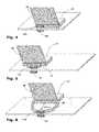
- FIG. 2is a schematic illustration of a computer provided with a secondary inductive coil incorporated within the base thereof, for inductively powering the computer by bringing into proximity with a power supplying inductive coil, according to another embodiment of the invention
- FIG. 3shows the jack sockets of a portable computer according to a further embodiment of the invention for coupling to an electricity mains power source via an inductive couple or via a conventional power supply;
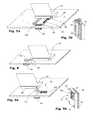
- FIG. 4is a schematic illustration of a computer carrying case according to another embodiment of the invention with an inductive power coil built into the base thereof;
- FIG. 5is a schematic illustration of another embodiment of the computer carrying case having an inductive power coil built into the handle thereof;
- FIG. 6is a schematic illustration of still another embodiment of the computer carrying case having an inductive power coil built into the shoulder strap thereof;
- FIGS. 7 a and 7 bare schematic illustrations of a retrofittable carrying handle for a portable computer with a built-in inductive power coil according to further embodiments of the invention.
- FIG. 8is a schematic illustration of a fashion-tag attachment with a built-in inductive power coil in accordance with still another embodiment of the invention.
- FIGS. 9 a and 9 bare schematic illustrations of a computer provided with another embodiment of the invention including a retractable secondary inductive coil attachment;
- FIG. 10is a schematic illustration of an inductive charger for a mobile communication device of a further embodiment of the invention.
- FIGS. 11 a and 11 bare schematic illustrations of a mobile communication device with an inductive charger built into the skin thereof according to another embodiment of the invention.
- FIG. 12 ais a schematic illustration of a self-adhesive inductive charger for a mobile communication device adhered to a power cell according to another embodiment of the invention.
- FIG. 12 bis a schematic illustration of how the self-adhesive inductive charger of FIG. 12 a may be used to charge cells;
- FIG. 13is a schematic illustration of an inductive charger of another embodiment of the invention having a hermaphrodite power connector
- FIGS. 14 a - care schematic illustrations of a protective case according to a further embodiment of the invention with a built-in an inductive charger for a mobile communication device;
- FIG. 15is a schematic illustration of a mobile communication device with an inductive charger built into a fashion tag
- FIG. 16is a schematic illustration of an inductive charger for a mobile communication device with a combined data connector
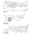
- FIG. 17is a block diagram showing the main elements of a charger for an audio device incorporated into an earphone unit in accordance with another embodiment of the invention.
- FIG. 18 ais a schematic diagram of a charger for an audio device according to another embodiment of the invention, wherein the voice coil of a speaker is wired to the power cell of the audio device and is inductively coupleable to a primary inductor;
- FIG. 18 bis a block diagram showing the main elements of a switching unit for connecting the charger of FIG. 18 a to an audio device;
- FIG. 19 ais a schematic diagram of another embodiment of the charger for an audio device wherein an induction loop is incorporated into a neck support of the earphone unit;
- FIG. 19 bis a schematic diagram of still another embodiment of the charger for an audio device wherein an induction loop is formed by connecting contact-terminals incorporated into the earphone cables;
- FIG. 19 cis a schematic representation of an embodiment of the charger for an audio device wherein an inductive core extends through an internal secondary coil and into the earphone unit for coupling with an external primary inductor;
- FIG. 20is a flowchart showing a possible method for charging the internal power cell of an audio device
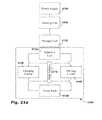
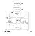
- FIGS. 21 a and 21 bare block diagrams schematically representing an inductive charger according a further embodiment of the invention in charging and driving modes respectively;
- FIG. 22 ais a schematic representation of another embodiment of the inductive charger being charged by a primary coil
- FIG. 22 bis a schematic representation of the inductive charger of FIG. 22 a being used to charge a mobile telephone wired to a secondary coil;
- FIG. 23 ais a schematic representation of a mobile computer being powered by a primary coil via an integral inductive coil according to another embodiment of the invention.
- FIG. 23 bis a schematic representation of a mobile telephone being charged by the inductive coil of FIG. 23 a.
- FIG. 1showing a power providing means 10 for a portable computer 12 consisting of a secondary inductor 14 wired to the portable computer by a connecting wire 15 that is typically a two stripe multi-fiber insulated wire, such as used for providing power to portable computers via a transformer.
- the secondary inductor 14is essentially a coil which can be brought into proximity with a primary inductor 16 which is essentially another coil hardwired to a mains power supply 18 .
- the primary coil 16 and secondary coil 14thus form an inductive power couple 20 , allowing power to be provided to the portable computer 12 .
- the primary coil 16may be situated in the table top 18 of a conference table, for example. By supplying power inductively in this manner, trailing wires may be avoided, providing a neater, safer and more flexible work environment.
- the power providing means 10may also be applicable to the provision of power to other electrical devices such as a desktop computer, handheld computer, vehicle mounted computer or the like. Power providing means 10 may also be used by other portable systems such as hand-held DVD players, projectors, hand-held televisions, digital picture frames or sound systems for example.
- the secondary coil 14may be integral to the portable computer 12 , being built into the base thereof, under the keyboard. Positioning the computer 12 over a primary coil 16 a in a work-surface 22 , for example, enables power to be provided thereto, without trailing wires. The power may be used to recharge the electrochemical power pack (battery) 24 or to power the portable computer 12 .
- the secondary coil 14 amay be coupled to a portable computer 12 designed for optional power provision in this manner, via a jack 26 that is plugged into a dedicated jack socket 28 designed for coupling the secondary coil 14 a .
- the dedicated jack socket 28is separate from the power supply jack socket 30 supplied for coupling to a power supply (not shown) of the type consisting of a transformer for plugging into a power mains socket that is typically provided.
- the dedicated jack plug 26 and jack socket 28may usefully be physically different from power supply jack socket 30 and jack plug (not shown), to prevent misconnection.
- the inductive and transformer sockets 28 , 30are preferably appropriately labeled, perhaps with letters I and T for inductive and transformer, to prevent confusion.
- the secondary coil 14 ais connected to the portable computer 12 via the power jack socket 30 designed for coupling to a mains via a power supply of the transformer type. In this manner, existing portable computers may be retrofitted with a secondary coil 14 a for inductive powering.
- Powermay alternatively be provided to the portable computer 12 via connecting points designed for coupling to a rechargeable electrochemical power pack within the housing for the power pack.
- the secondary coil 14 amay be provided as a sort of puck on a wire that can be positioned over an access point in a surface where a primary coil 16 is provided.
- the secondary coil 14 bis preferably incorporated into an accessory that has additional functionality.
- itmay be built into the side of a carrying case 40 or skin provided for carrying the portable computer 12 .
- the secondary coil 14 cis built into the handle 42 of a carrying case 44 .
- the secondary coil 14 dis built into the shoulder strap 46 of a carrying case 48 which being flexible, gives more flexibility to the user, in that the computer 12 can be left in its case, and situated anywhere within a radius of about 80 cm from a “power-spot” where a primary coil 16 is situated.
- a retrofittable carrying handle 52 for a computer 12is shown.
- the handle 52is attached to the computer by straps 54 and incorporates a built-in inductive power coil 14 e electrically coupled to the computer via a power plug 56 which plugs into the power jack 30 of the computer 12 .
- the straps 54surround and support the computer 12 as shown in FIG. 7 b . However, as shown in FIG. 7 a , when the computer 12 is laid down and in use, the support straps 54 are opened allowing the inductive power coil 14 e to be coupled to a primary coil 16 situated anywhere within their radius.
- the inductive power coil 14may be concealed inside a fashion-tag 62 attached to the computer 12 for example by a connecting chain 64 or the like.
- the computermay draw power from a primary coil 16 .
- a retractable secondary inductive coil attachment 70may be retrofitted to a portable computer 12 , as shown in FIGS. 9 a and 9 b .
- the secondary inductive coil 14 fis held in a tongue 74 mounted upon the base of the computer 12 and when the computer 12 is in use as shown in FIG. 9 a , the tongue 74 may be extended so that the secondary coil 14 f may couple with a power spot 16 within its radius.
- tongue 74may be retracted.
- the thickness of the secondary inductive coil attachment 70is less than the height of the feet 13 of the computer 12 so that the attachment 70 does not prevent the computer 12 lying flat along a table top.
- an inductive charger 100for charging the power cells of a mobile communication device 200 such as mobile telephone, personal digital assistant (PDA), camera or the like, indeed many mobile devices include all of these functions.
- the charger 100consists of a secondary coil 120 wired to the mobile communication device 200 typically via a power jack socket 220 of by a connecting wire 140 —typically a two stripe multi-fiber insulating wire, such as used for electrically connecting a power source to a mobile communication device via a transformer.
- the secondary coil 120can be brought into proximity with a primary coil 10 hardwired to a mains power supply, to form an inductive power couple, allowing power to be provided to recharge the cells 240 ( FIGS. 12 a and 12 b ) of the mobile communication device 200 .
- the primary coil 10may be situated in the table top 20 of a conference table, for example, thereby allowing a phone 200 to be recharged thereby. By inductively recharging in this manner, trailing wires may be avoided or at least minimized.
- the secondary coil 120may be provided for example as a sort of puck 122 on a wire that can be positioned over an access point in a surface where a primary coil 10 is provided. Alternatively the secondary coil 120 may be built into an accessory of the telephone 200 .
- the secondary coil 120may be built into the skin or casing 260 a , 260 b of the mobile communication device. Positioning the mobile communication device over a primary coil 10 , as shown in FIG. 11 b , at an access point in a work-surface 20 , for example, enables power to be provided to the charger thereby charging the power cells 240 of the mobile communication device 200 without trailing wires.
- the chargermay be connected directly to the terminals of the power cells. Alternatively the charger may be connected to the power cells via the power jack socket 220 of the mobile communication device 200 .
- the secondary coil 120may be provided with an adhesive surface 122 so that the coil 120 may be adhered directly onto the power cells 240 of a mobile telecommunication device 200 in conductive contact with the terminals of the power cells.
- the cells 240may be recharged.
- FIG. 12 bit is noted that in this embodiment, the cells 240 are recharged directly from the secondary coil 120 so the cells 240 do not need to be connected to the device in order for them to be charged.
- the secondary coil 120is wired to a hermaphrodite power connector 160 including both a male plug 162 and a female socket 164 .
- the male plug 162 of the hermaphrodite power connector 160may be coupled to the power jack socket 220 of the device while still providing a female socket 164 for accommodating the plug 40 of a conventional conductive charger.
- a usermay select between charging the power cells 240 of the mobile communication device 200 using the inductive charger 100 or the conductive type charger.
- the selectionmay be facilitated by means of a switch although, preferably, the power connector 160 is configured automatically to select the inductive charger whenever the secondary coil 120 is inductively coupled to a primary coil 10 and to select the conductive power supply whenever the female socket 164 is conductively coupled to a power source.
- the secondary coil 120may be built into a protective or fashionable case 300 which may be fitted to a mobile communication device 200 .
- the secondary coil 120is typically wired to a hermaphrodite power connector 160 within the case 300 which is configured to couple with the power jack socket 220 of the mobile communication device.
- FIG. 15A further embodiment is illustrated in FIG. 15 showing a mobile communication device 200 having a secondary coil concealed within a fashionable tag 400 , such as a so called “mobile dangler” or the like, which may be plugged directly into the power jack socket 220 with additional mechanical support 420 optionally provided when necessary.
- the inductive charger 100 of the inventionmay thus be incorporated within a fashion accessory for the mobile communication device.
- the secondary coil 120may be concealed in other accessories of the mobile telecommunication device such as a belt clip, neck cord, hand strap or the like.
- an inductive charger 700has a data channel coupled to the data jack socket 280 of the mobile communication device 200 .
- a USB (Universal Serial Bus) cable 720 leading to a USB plugis wired to the inductive charger which may be connected to USB jack socket 820 of a computer 800 , for example, thereby providing a data link between the mobile communication device 200 and the computer 800 .
- USBUniversal Serial Bus
- the USB connector 740may, in addition, draw power from the computer 800 and may thus be used to provide power to charge the power cells 120 of the mobile communication device 200 directly.
- the charger 700may be configured to select automatically between charging the power cells 120 from the USB connector 740 or the secondary coil 120 depending upon the availability of power.
- U.S. Pat. No. 7,180,265 to Nokia Corporation, titled “Charging Device with an Induction Coil”describes an inductive charging device for charging portable electronic devices with small footprints.
- the charger described in '265includes a battery; a first induction coil coupled to the battery; and an induction core extending through the first induction coil.
- the induction corehas a portion which extends in an outward direction from the charging device and is adapted to removably couple with a second induction coil of a portable electronic device by extending into the second induction coil.
- the charger described in '265is essentially a charging hook upon which electronic devices may be suspended by support loops.
- the hookis coupled to the first inductive coil and is adapted to charge up the electronic devices via the secondary inductive coils which may be incorporated into the support loops.
- the support strap itselfis undesirable, and as discussed hereinabove, there is a general desire to limit the number of wires, straps and cables.
- FIG. 17a block diagram showing the main elements of an inductive charger 1100 for charging the internal power cells 1220 of an audio device 1200 , according to an embodiment of the invention.
- the charger 1100includes a secondary inductor 1140 wired to the power cells 1220 of the audio device 1200 via a rectifier 1240 .
- An inductive element 1180is incorporated into the earphone unit 1120 for inductively coupling the secondary inductor 1140 to an external primary inductor 1320 .
- the primary inductor 1320is typically wired to a power supply 1300 via a driving unit 1310 .
- the driving unit 1310provides the electronics necessary to drive the primary inductor 1320 , such as a switching unit providing a high frequency oscillating voltage supply, for example.
- Charger 1100is suitable for use with audio devices 1200 requiring earphones 1121 connected via earphone cables 1122 such as, telephones, media players, personal digital assistants (PDA), Walkman®s, portable CD players, portable DVD players, mobile communications devices and the like.
- earphones 1121connected via earphone cables 1122
- PDApersonal digital assistants
- Walkman®sportable CD players
- portable DVD playersportable DVD players
- mobile communications devicesand the like.
- the inductive charger 1100is incorporated in the earphone unit 1120 of the audio device 1200 .
- the inductive charger 1100 of the present inventionis incorporated into the earphone unit 1120 , the dimensions of the audio device 1200 itself are not compromised by the addition of peripheral elements such as the support strap described in U.S. Pat. No. 7,180,265 to Nokia Corporation, for example.
- the earphone unit 2120includes a moving coil speaker 2122 incorporated within an earpiece 2124 which is connected via a signal line 2125 to a plug 2126 for coupling to the audio device 2200 via an earphone jack 2202 .
- the voice coil 2140 of the moving coil speaker 2122is a transducer that receives electrical signals from the signal lines 2125 and converts them to audio signals.
- the voice coil 2140is additionally configured to be couplable to an external primary inductor 2320 which may be housed within a docking station 2322 .
- the voice coil 2140may serve as the secondary inductor 1140 ( FIG. 17 ) of the inductive charger 2100 , providing power to the audio device via the signal lines 2125 .
- dedicated power lines within the earphone unit 2120may provide a conductive connection between the voice coil 2140 and the internal power cell 220 of the audio device 200 via a rectifier 1240 ( FIG. 17 ).
- FIG. 18 bis a block diagram of the main elements of a switching unit 2270 for connecting the charger 2100 of FIG. 18 a to an audio device 2200 .
- the switching unit 2270is provided to selectively connect the voice coil 2140 to the audio device 2200 .
- the switching unit 2270may be a separate unit that is retrofittable both to the audio device 2200 and to the earphone unit 2120 . Alternatively, the switching unit 2270 may be incorporated into either the audio device 2200 or the earphone unit 2120 .
- the switching unit 2270may connect the voice coil terminal C to either an audio signal input A or to a charger output B of a switching circuit 2272 .
- the audio signal input Areceives an audio signal 2250 from an amplifier 2260 which is communicated to the voice coil 2140 .
- the charger output Bis connected to the power cell 2220 via a rectifier 2240 and may be used for charging the power cell 2220 when the voice coil 2140 is coupled to primary inductor 2320 .
- the switching circuit 2272may be controlled by a frequency detector 2274 which is configured and operable to detect high frequency voltage fluctuations along the signal line. High frequency voltage fluctuations are indicative that the voice coil 2140 is coupled to an active primary inductor 2320 . Therefore, when such high frequency fluctuations are detected, the switching circuit 2272 may be connected to the charger output B for charging the power cell 2220 .
- FIGS. 19 a - care schematic diagrams showing various embodiments of charger 3100 , 4100 , 5100 for an audio device 3200 , 4200 , 5200 .
- the earphone unit 3120includes a neck support 3122 .
- an induction loop 3140 of conductive wire 3142that is wound into a coil and connected to the internal power cell 1220 ( FIG. 17 ) of the audio device 3200 via a rectifier 1240 ( FIG. 17 ).
- the inductive loop 3140is configured to inductively couple with an external primary inductor 320 .
- the audio device 3200may be conveniently stored by suspending the neck support 3122 from a hook 3322 .
- the hook 3322is fabricated from a ferromagnetic material which extends through a primary coil 3320 .
- the ferromagnetic materialforms a common inductive core 3180 between the primary coil 3320 and the inductive loop 3140 within the neck support 3122 .
- the primary coil 3320 and inductive loop 3140thus form an inductive couple such that power may be inductively transferred from the primary coil 3320 to the inductive loop 3140 , thereby charging the power cells 1220 ( FIG. 17 ) of the audio device 3200 .
- the inductive couplemay be improved by the inclusion of a ferromagnetic element (not shown) and may be incorporated into the neck support 3122 and configured so as to couple with the ferromagnetic inductive core 3180 of the hook 3322 so as to complete a magnetic circuit.
- a ferromagnetic element(not shown) and may be incorporated into the neck support 3122 and configured so as to couple with the ferromagnetic inductive core 3180 of the hook 3322 so as to complete a magnetic circuit.
- a secondary inductormay be housed in various other components of an earphone unit.
- a secondary induction coilmay be housed in a dedicated unit within the earphone cable.
- a secondary coilmay be incorporated into a microphone housing such as is commonly included in the earphone cable of a cellular telephone.
- a secondary coilmay be incorporated into a cable stowage unit such as a spring loaded winder as is sometimes included with earphone units for convenient storage.
- FIG. 19 bAn alternative embodiment of the induction loop is schematically represented in FIG. 19 b , wherein a charger 4100 for an audio device 4200 according to another embodiment of the current invention is shown.
- the earphone unit 4120 of this embodimentincludes two earpieces 4122 a , 4122 b , each connected to the audio device 4200 via its own earphone cable 4124 a , 4124 b .
- a bundle of induction wires 4140embedded in the earphone cables 4124 , is connected to the internal power cell 1220 ( FIG. 17 ) of the audio device 4200 via the rectifier 1240 ( FIG. 17 ).
- Contact-terminals 4142 a and 4142 b at each end of the bundle of induction wires 4140are configured to conductively couple the ends of the bundle of induction wires 4140 thereby forming an induction loop.
- the induction loopmay be coupled with an external primary coil (not shown) such that power may be inductively transferred from the primary coil to the inductive loop.
- FIG. 19 cis a schematic representation of a charger 5100 for an audio device 5200 according to still another embodiment of the invention.
- the audio device 5200incorporates an internal secondary coil 5140 connected to the internal power cell 5220 via the rectifier 5240 .
- An inductive core 5180extends through the internal secondary coil 5140 and into the earphone unit 5120 for coupling with a primary inductor 5320 .
- the primary inductormay, for example, be incorporated into a hook (not shown) for suspending the audio device 5200 .
- FIG. 20is a flowchart showing a method for inductively charging the internal power cell of an audio device in accordance with one embodiment of the invention. The method comprises the steps of:
- step (a)providing an inductive charger incorporated within the earphone unit of the audio device, including a secondary inductor connected to the power cell via a rectifier;
- step (b)providing an external primary inductor connected to a power source via a driver
- step (c)inductively coupling the secondary inductor of the charger to the external primary inductor
- step (d)providing a variable voltage to the primary inductor.
- FIGS. 21 a and 21 bare block diagrams schematically representing the inductive charger 6100 for use with another embodiment of the invention.
- the inductive charger 6100consists of an inductive coil 6120 and a chargeable power pack 6140 which can be connected to each other via a charging circuit 6160 or alternatively via a driving circuit 6180 . It is a particular feature of the current invention that the inductive charger 6100 may be switched between two modes: (a) a charging mode as shown in FIG. 21 a , and (b) a driving mode, as shown in FIG. 21 b .
- a mode selector 6170is used to select between the two modes.
- the inductive coil 6120is coupled to an external primary inductive coil 6220 which is connected to a power supply 6240 preferably via a driving unit 6260 .
- the mode selector 6170is configured to connect the inductive coil 6120 to the power pack 6140 via the charging circuit 6160 .
- the external primary coil 6220In the charging mode, the external primary coil 6220 generates an oscillating magnetic field.
- the internal inductive coil 6120is placed in the vicinity of the external primary coil 6220 , thereby creating a magnetic flux linkage between the primary coil 6220 and the internal inductive coil 6120 , by which power is transferred from the external primary coil 6220 to the internal inductive coil 6120 .
- direct currentis required for reversing the electrochemical reactions that result in power supply from the power packs and the charging circuit 6160 rectifies the alternating current generated in the inductive coil 6120 thereby allowing the power pack 6140 to be recharged.
- the mode selector 6170is configured to connect the inductive coil 6120 to the power pack 6140 via the driving circuit 6180 .
- the power supply 6140provides power to the driver circuit 6180 which provides a varying electrical potential to drive the inductive coil 6120 .
- the driver circuit 6180typically includes a high frequency switching unit intermittently connecting the power pack 6140 to the inductive coil 6120 .
- the varying electrical potential across the inductive coil 6120produces an oscillating magnetic field. Therefore, an external secondary coil 6320 which is brought into the vicinity of the inductive charger 6100 may inductively couple with the inductive coil 6120 .
- An electric load 6340 wired to the secondary coil 6320may thereby draw power from the power pack 6140 .
- rechargeable power packsare known and may be suitable for use with various embodiments of the inductive charger 6100 .
- rechargeable electrochemical cellsinclude nickel-cadmium cells, nickel metal hydride cells, alkaline cells, flow batteries and the like.
- Other power storage devicessuch as lead alkali accumulators, capacitors and supercapacitors may also be charged by the inductive charger 6100 .
- FIGS. 22 a and 22 bshowing an exemplary inductive charger 7100 according to another embodiment of the invention.
- a housing 7110contains an inductive coil 7120 which is wrapped around a ferromagnetic core 7122 and is connected to an internal power pack 7140 via a control box 7130 .
- the control box 7130contains driving circuitry for the driving mode, charging circuitry for the charging mode and a mode selector (not shown).
- additional circuitrymay be provided for charging the power pack 7140 from the mains or other external power source, such as solar power or the like, via a dedicated jack.
- a dedicated jackmay also be provided for conductively connecting with and the powering of an external electrical load.
- FIG. 22 ashows the inductive charger 7100 being charged up by an inductive power outlet 7200 which consists of a primary coil 7220 concealed behind a facing layer, such as Formica or wood veneer, of a platform 7280 such as a desk-top, a kitchen work-top, a conference table or a work bench for example.
- the primary coil 7220is wired to a power supply 7240 via a driving unit 7260 providing the electronics necessary to drive the primary coil 7120 .
- Driving electronicsmay include a switching unit providing a high frequency oscillating voltage supply, for example.
- inductive power outlets 7200As inductive power outlets 7200 become more widespread, it is considered likely that devices may be hardwired to secondary coils, to draw their power inductively therefrom.
- mobile phones, media players and the likewhich are generally connected to external chargers via connecting wires may be provided with internal charging circuitry that includes a secondary coil for inductively coupling to inductive power outlet 7200 .
- FIG. 22 bshows a mobile phone 7300 which has an integral secondary inductive coil 7320 connected to its internal power source 7340 via a rectifier (not shown).
- the mobile phone 7300may be charged by placing it over an inductive power outlet 7200 such as shown in FIG. 22 a , thereby inductively coupling the secondary coil 7320 of the device with the primary coil of the outlet 7200 .
- the mobile phonemay be charged by placing it on top of the inductive charger 7100 , as shown in FIG. 7 b .
- the mobile phones secondary coil 7320inductively couples with the internal inductive coil 7120 of the inductive charger 7100 and draws power therefrom.
- the inductive charger 8100is incorporated into a mobile computer 8000 .
- the mobile computer 8000has a built-in inductive coil 8120 for powering the computer from an inductive power outlet 8200 , as shown in FIG. 23 a .
- the inductive coil 8120may power the computer and/or charge the internal power pack 8140 of the mobile computer.
- the inductive coil 8120 of the computer 8000may additionally be used to charge an external device such as a mobile phone 8300 with an in-built secondary coil 8320 , as shown in FIG. 8 b .
- an external devicesuch as a mobile phone 8300 with an in-built secondary coil 8320 , as shown in FIG. 8 b .
- a similar useis already made of computers 8000 to charge external devices such as media players, mobile phones, mice, Bluetooth devices and the like, generally using dedicated cables and via standard ports, such as their USB (universal serial bus) ports.
- USBuniversal serial bus
- inductive chargersmay be incorporated into other hosts, such as electric cars, generators, emergency lights or the like for charging electrical devices thereby.
Landscapes
- Engineering & Computer Science (AREA)
- Power Engineering (AREA)
- Computer Networks & Wireless Communication (AREA)
- Theoretical Computer Science (AREA)
- Physics & Mathematics (AREA)
- General Engineering & Computer Science (AREA)
- General Physics & Mathematics (AREA)
- Charge And Discharge Circuits For Batteries Or The Like (AREA)
Abstract
Description
Claims (10)
Priority Applications (2)
| Application Number | Priority Date | Filing Date | Title |
|---|---|---|---|
| US12/693,001US8193769B2 (en) | 2007-10-18 | 2010-01-25 | Inductively chargeable audio devices |
| US13/475,383US20120230521A1 (en) | 2007-10-18 | 2012-05-18 | Inductively chargeable audio devices |
Applications Claiming Priority (5)
| Application Number | Priority Date | Filing Date | Title |
|---|---|---|---|
| US96087807P | 2007-10-18 | 2007-10-18 | |
| US613107P | 2007-12-26 | 2007-12-26 | |
| US6440308P | 2008-03-04 | 2008-03-04 | |
| PCT/IL2008/001348WO2009047769A2 (en) | 2007-10-09 | 2008-10-12 | Inductive receivers for electrical devices |
| US12/693,001US8193769B2 (en) | 2007-10-18 | 2010-01-25 | Inductively chargeable audio devices |
Related Parent Applications (1)
| Application Number | Title | Priority Date | Filing Date |
|---|---|---|---|
| PCT/IL2008/001348ContinuationWO2009047769A2 (en) | 2007-10-09 | 2008-10-12 | Inductive receivers for electrical devices |
Related Child Applications (1)
| Application Number | Title | Priority Date | Filing Date |
|---|---|---|---|
| US13/475,383ContinuationUS20120230521A1 (en) | 2007-10-18 | 2012-05-18 | Inductively chargeable audio devices |
Publications (2)
| Publication Number | Publication Date |
|---|---|
| US20100194336A1 US20100194336A1 (en) | 2010-08-05 |
| US8193769B2true US8193769B2 (en) | 2012-06-05 |
Family
ID=42397146
Family Applications (5)
| Application Number | Title | Priority Date | Filing Date |
|---|---|---|---|
| US12/693,001ActiveUS8193769B2 (en) | 2007-10-18 | 2010-01-25 | Inductively chargeable audio devices |
| US12/757,600ActiveUS7906936B2 (en) | 2007-10-09 | 2010-04-09 | Rechargeable inductive charger |
| US12/757,615Active2029-09-26US8380998B2 (en) | 2007-10-09 | 2010-04-09 | Inductive receivers for electrical devices |
| US13/475,383AbandonedUS20120230521A1 (en) | 2007-10-18 | 2012-05-18 | Inductively chargeable audio devices |
| US13/741,799ActiveUS8762749B2 (en) | 2007-10-09 | 2013-01-15 | Inductive receivers for electrical devices |
Family Applications After (4)
| Application Number | Title | Priority Date | Filing Date |
|---|---|---|---|
| US12/757,600ActiveUS7906936B2 (en) | 2007-10-09 | 2010-04-09 | Rechargeable inductive charger |
| US12/757,615Active2029-09-26US8380998B2 (en) | 2007-10-09 | 2010-04-09 | Inductive receivers for electrical devices |
| US13/475,383AbandonedUS20120230521A1 (en) | 2007-10-18 | 2012-05-18 | Inductively chargeable audio devices |
| US13/741,799ActiveUS8762749B2 (en) | 2007-10-09 | 2013-01-15 | Inductive receivers for electrical devices |
Country Status (1)
| Country | Link |
|---|---|
| US (5) | US8193769B2 (en) |
Cited By (103)
| Publication number | Priority date | Publication date | Assignee | Title |
|---|---|---|---|---|
| US20100259110A1 (en)* | 2008-09-27 | 2010-10-14 | Kurs Andre B | Resonator optimizations for wireless energy transfer |
| US20110095618A1 (en)* | 2008-09-27 | 2011-04-28 | Schatz David A | Wireless energy transfer using repeater resonators |
| US20110204842A1 (en)* | 2010-02-19 | 2011-08-25 | Terumasa Nagasaki | Charger, electronic apparatus, and storage case |
| US20120091949A1 (en)* | 2008-09-27 | 2012-04-19 | Campanella Andrew J | Wireless energy transfer for energizing power tools |
| US8432073B2 (en)* | 2009-07-16 | 2013-04-30 | Silicon Touch Technology Inc. | Power generating device |
| US8669676B2 (en) | 2008-09-27 | 2014-03-11 | Witricity Corporation | Wireless energy transfer across variable distances using field shaping with magnetic materials to improve the coupling factor |
| US8692412B2 (en) | 2008-09-27 | 2014-04-08 | Witricity Corporation | Temperature compensation in a wireless transfer system |
| US8723366B2 (en) | 2008-09-27 | 2014-05-13 | Witricity Corporation | Wireless energy transfer resonator enclosures |
| US8772973B2 (en) | 2008-09-27 | 2014-07-08 | Witricity Corporation | Integrated resonator-shield structures |
| US20140191714A1 (en)* | 2013-01-04 | 2014-07-10 | Primax Electronics Ltd. | Wireless transmitting device for wireless charging |
| US8847548B2 (en) | 2008-09-27 | 2014-09-30 | Witricity Corporation | Wireless energy transfer for implantable devices |
| US8875086B2 (en) | 2011-11-04 | 2014-10-28 | Witricity Corporation | Wireless energy transfer modeling tool |
| US8901778B2 (en) | 2008-09-27 | 2014-12-02 | Witricity Corporation | Wireless energy transfer with variable size resonators for implanted medical devices |
| US8901779B2 (en) | 2008-09-27 | 2014-12-02 | Witricity Corporation | Wireless energy transfer with resonator arrays for medical applications |
| US8907531B2 (en) | 2008-09-27 | 2014-12-09 | Witricity Corporation | Wireless energy transfer with variable size resonators for medical applications |
| US8912687B2 (en) | 2008-09-27 | 2014-12-16 | Witricity Corporation | Secure wireless energy transfer for vehicle applications |
| US8922066B2 (en) | 2008-09-27 | 2014-12-30 | Witricity Corporation | Wireless energy transfer with multi resonator arrays for vehicle applications |
| US8928276B2 (en) | 2008-09-27 | 2015-01-06 | Witricity Corporation | Integrated repeaters for cell phone applications |
| US8933594B2 (en) | 2008-09-27 | 2015-01-13 | Witricity Corporation | Wireless energy transfer for vehicles |
| US8937408B2 (en) | 2008-09-27 | 2015-01-20 | Witricity Corporation | Wireless energy transfer for medical applications |
| US8947186B2 (en) | 2008-09-27 | 2015-02-03 | Witricity Corporation | Wireless energy transfer resonator thermal management |
| US8946938B2 (en) | 2008-09-27 | 2015-02-03 | Witricity Corporation | Safety systems for wireless energy transfer in vehicle applications |
| US8957549B2 (en) | 2008-09-27 | 2015-02-17 | Witricity Corporation | Tunable wireless energy transfer for in-vehicle applications |
| US8963488B2 (en) | 2008-09-27 | 2015-02-24 | Witricity Corporation | Position insensitive wireless charging |
| US9035499B2 (en) | 2008-09-27 | 2015-05-19 | Witricity Corporation | Wireless energy transfer for photovoltaic panels |
| US9065423B2 (en) | 2008-09-27 | 2015-06-23 | Witricity Corporation | Wireless energy distribution system |
| US9093853B2 (en) | 2008-09-27 | 2015-07-28 | Witricity Corporation | Flexible resonator attachment |
| US9095729B2 (en) | 2007-06-01 | 2015-08-04 | Witricity Corporation | Wireless power harvesting and transmission with heterogeneous signals |
| US20150222138A1 (en)* | 2014-02-06 | 2015-08-06 | Lenovo (Singapore) Pte. Ltd. | Wireless charging system for multi-mode device |
| US9106203B2 (en) | 2008-09-27 | 2015-08-11 | Witricity Corporation | Secure wireless energy transfer in medical applications |
| US9105959B2 (en) | 2008-09-27 | 2015-08-11 | Witricity Corporation | Resonator enclosure |
| US9160203B2 (en) | 2008-09-27 | 2015-10-13 | Witricity Corporation | Wireless powered television |
| US9184595B2 (en) | 2008-09-27 | 2015-11-10 | Witricity Corporation | Wireless energy transfer in lossy environments |
| US9246336B2 (en) | 2008-09-27 | 2016-01-26 | Witricity Corporation | Resonator optimizations for wireless energy transfer |
| US9287607B2 (en) | 2012-07-31 | 2016-03-15 | Witricity Corporation | Resonator fine tuning |
| US9306635B2 (en) | 2012-01-26 | 2016-04-05 | Witricity Corporation | Wireless energy transfer with reduced fields |
| US9318922B2 (en) | 2008-09-27 | 2016-04-19 | Witricity Corporation | Mechanically removable wireless power vehicle seat assembly |
| US9318257B2 (en) | 2011-10-18 | 2016-04-19 | Witricity Corporation | Wireless energy transfer for packaging |
| US9343922B2 (en) | 2012-06-27 | 2016-05-17 | Witricity Corporation | Wireless energy transfer for rechargeable batteries |
| US9369182B2 (en) | 2008-09-27 | 2016-06-14 | Witricity Corporation | Wireless energy transfer using variable size resonators and system monitoring |
| US9384885B2 (en) | 2011-08-04 | 2016-07-05 | Witricity Corporation | Tunable wireless power architectures |
| US9396867B2 (en) | 2008-09-27 | 2016-07-19 | Witricity Corporation | Integrated resonator-shield structures |
| US9404954B2 (en) | 2012-10-19 | 2016-08-02 | Witricity Corporation | Foreign object detection in wireless energy transfer systems |
| US9421388B2 (en) | 2007-06-01 | 2016-08-23 | Witricity Corporation | Power generation for implantable devices |
| US9442172B2 (en) | 2011-09-09 | 2016-09-13 | Witricity Corporation | Foreign object detection in wireless energy transfer systems |
| US9444520B2 (en) | 2008-09-27 | 2016-09-13 | Witricity Corporation | Wireless energy transfer converters |
| US9449757B2 (en) | 2012-11-16 | 2016-09-20 | Witricity Corporation | Systems and methods for wireless power system with improved performance and/or ease of use |
| US9515494B2 (en) | 2008-09-27 | 2016-12-06 | Witricity Corporation | Wireless power system including impedance matching network |
| US9544683B2 (en) | 2008-09-27 | 2017-01-10 | Witricity Corporation | Wirelessly powered audio devices |
| US9595378B2 (en) | 2012-09-19 | 2017-03-14 | Witricity Corporation | Resonator enclosure |
| US9601270B2 (en) | 2008-09-27 | 2017-03-21 | Witricity Corporation | Low AC resistance conductor designs |
| US9602168B2 (en) | 2010-08-31 | 2017-03-21 | Witricity Corporation | Communication in wireless energy transfer systems |
| US9601266B2 (en) | 2008-09-27 | 2017-03-21 | Witricity Corporation | Multiple connected resonators with a single electronic circuit |
| US20170104355A1 (en)* | 2015-10-07 | 2017-04-13 | Motorola Solutions, Inc | Apparatus, method and system for providing expanded functionality to communication devices using wireless charging coil-in-coil |
| US9744858B2 (en) | 2008-09-27 | 2017-08-29 | Witricity Corporation | System for wireless energy distribution in a vehicle |
| US9754718B2 (en) | 2008-09-27 | 2017-09-05 | Witricity Corporation | Resonator arrays for wireless energy transfer |
| US9780573B2 (en) | 2014-02-03 | 2017-10-03 | Witricity Corporation | Wirelessly charged battery system |
| US9793739B2 (en) | 2013-08-07 | 2017-10-17 | Sandisk Technologies Llc | Wireless power transmitting device |
| US9805864B2 (en) | 2014-04-04 | 2017-10-31 | Apple Inc. | Inductive spring system |
| US9837860B2 (en) | 2014-05-05 | 2017-12-05 | Witricity Corporation | Wireless power transmission systems for elevators |
| US9842687B2 (en) | 2014-04-17 | 2017-12-12 | Witricity Corporation | Wireless power transfer systems with shaped magnetic components |
| US9842688B2 (en) | 2014-07-08 | 2017-12-12 | Witricity Corporation | Resonator balancing in wireless power transfer systems |
| US9843217B2 (en) | 2015-01-05 | 2017-12-12 | Witricity Corporation | Wireless energy transfer for wearables |
| US9857821B2 (en) | 2013-08-14 | 2018-01-02 | Witricity Corporation | Wireless power transfer frequency adjustment |
| US9892849B2 (en) | 2014-04-17 | 2018-02-13 | Witricity Corporation | Wireless power transfer systems with shield openings |
| US9929721B2 (en) | 2015-10-14 | 2018-03-27 | Witricity Corporation | Phase and amplitude detection in wireless energy transfer systems |
| US9948145B2 (en) | 2011-07-08 | 2018-04-17 | Witricity Corporation | Wireless power transfer for a seat-vest-helmet system |
| US9952266B2 (en) | 2014-02-14 | 2018-04-24 | Witricity Corporation | Object detection for wireless energy transfer systems |
| US9954375B2 (en) | 2014-06-20 | 2018-04-24 | Witricity Corporation | Wireless power transfer systems for surfaces |
| US10018744B2 (en) | 2014-05-07 | 2018-07-10 | Witricity Corporation | Foreign object detection in wireless energy transfer systems |
| US10032557B1 (en) | 2014-05-29 | 2018-07-24 | Apple Inc. | Tuning of primary and secondary resonant frequency for improved efficiency of inductive power transfer |
| US10044232B2 (en) | 2014-04-04 | 2018-08-07 | Apple Inc. | Inductive power transfer using acoustic or haptic devices |
| US10063104B2 (en) | 2016-02-08 | 2018-08-28 | Witricity Corporation | PWM capacitor control |
| US10063110B2 (en) | 2015-10-19 | 2018-08-28 | Witricity Corporation | Foreign object detection in wireless energy transfer systems |
| US10062492B2 (en) | 2014-04-18 | 2018-08-28 | Apple Inc. | Induction coil having a conductive winding formed on a surface of a molded substrate |
| US10075019B2 (en) | 2015-11-20 | 2018-09-11 | Witricity Corporation | Voltage source isolation in wireless power transfer systems |
| US10135303B2 (en) | 2014-05-19 | 2018-11-20 | Apple Inc. | Operating a wireless power transfer system at multiple frequencies |
| US10141788B2 (en) | 2015-10-22 | 2018-11-27 | Witricity Corporation | Dynamic tuning in wireless energy transfer systems |
| US10158244B2 (en) | 2015-09-24 | 2018-12-18 | Apple Inc. | Configurable wireless transmitter device |
| US10218224B2 (en) | 2008-09-27 | 2019-02-26 | Witricity Corporation | Tunable wireless energy transfer systems |
| US10248899B2 (en) | 2015-10-06 | 2019-04-02 | Witricity Corporation | RFID tag and transponder detection in wireless energy transfer systems |
| US10263473B2 (en) | 2016-02-02 | 2019-04-16 | Witricity Corporation | Controlling wireless power transfer systems |
| US20190141425A1 (en)* | 2011-09-06 | 2019-05-09 | Kohler Co. | Speaker and shower |
| US10404089B2 (en) | 2014-09-29 | 2019-09-03 | Apple Inc. | Inductive charging between electronic devices |
| US10424976B2 (en) | 2011-09-12 | 2019-09-24 | Witricity Corporation | Reconfigurable control architectures and algorithms for electric vehicle wireless energy transfer systems |
| US10477741B1 (en) | 2015-09-29 | 2019-11-12 | Apple Inc. | Communication enabled EMF shield enclosures |
| US10574091B2 (en) | 2014-07-08 | 2020-02-25 | Witricity Corporation | Enclosures for high power wireless power transfer systems |
| US10594160B2 (en) | 2017-01-11 | 2020-03-17 | Apple Inc. | Noise mitigation in wireless power systems |
| US10651685B1 (en) | 2015-09-30 | 2020-05-12 | Apple Inc. | Selective activation of a wireless transmitter device |
| US10714985B2 (en) | 2017-10-11 | 2020-07-14 | Spark Connected LLC | Wireless power transfer system and method |
| US10734840B2 (en) | 2016-08-26 | 2020-08-04 | Apple Inc. | Shared power converter for a wireless transmitter device |
| US10790699B2 (en) | 2015-09-24 | 2020-09-29 | Apple Inc. | Configurable wireless transmitter device |
| US10873204B2 (en) | 2014-09-29 | 2020-12-22 | Apple Inc. | Inductive coupling assembly for an electronic device |
| US20210083509A1 (en)* | 2019-09-12 | 2021-03-18 | Spark Connected LLC | Electronic Device, Wireless Charger and Wireless Charging System |
| US10998121B2 (en) | 2014-09-02 | 2021-05-04 | Apple Inc. | Capacitively balanced inductive charging coil |
| US11031818B2 (en) | 2017-06-29 | 2021-06-08 | Witricity Corporation | Protection and control of wireless power systems |
| US11152823B2 (en) | 2019-04-01 | 2021-10-19 | Spark Connected LLC | Translation unit for wireless power transfer |
| US11509169B2 (en) | 2019-02-13 | 2022-11-22 | Spark Connected LLC | Sub-surface wireless charging |
| US11515739B2 (en) | 2020-02-14 | 2022-11-29 | Spark Connected LLC | FOD and wireless power transfer calibration |
| US11855463B2 (en) | 2020-12-04 | 2023-12-26 | Spark Connected LLC | Wireless power transmission to a mobile device |
| US11888331B2 (en) | 2020-07-01 | 2024-01-30 | Spark Connected LLC | Sub-surface wireless charging and associated method |
| US12053055B2 (en) | 2020-05-15 | 2024-08-06 | Spark Connected LLC | Dual function wireless power and thermal receiver |
| US12068631B2 (en) | 2020-04-13 | 2024-08-20 | Spark Connected LLC | Alignment method for sub-surface wireless charger |
Families Citing this family (112)
| Publication number | Priority date | Publication date | Assignee | Title |
|---|---|---|---|---|
| US7065658B1 (en) | 2001-05-18 | 2006-06-20 | Palm, Incorporated | Method and apparatus for synchronizing and recharging a connector-less portable computer system |
| US8169185B2 (en) | 2006-01-31 | 2012-05-01 | Mojo Mobility, Inc. | System and method for inductive charging of portable devices |
| US7952322B2 (en)* | 2006-01-31 | 2011-05-31 | Mojo Mobility, Inc. | Inductive power source and charging system |
| US11201500B2 (en) | 2006-01-31 | 2021-12-14 | Mojo Mobility, Inc. | Efficiencies and flexibilities in inductive (wireless) charging |
| US11329511B2 (en) | 2006-06-01 | 2022-05-10 | Mojo Mobility Inc. | Power source, charging system, and inductive receiver for mobile devices |
| US7948208B2 (en) | 2006-06-01 | 2011-05-24 | Mojo Mobility, Inc. | Power source, charging system, and inductive receiver for mobile devices |
| CN101802942A (en) | 2007-01-29 | 2010-08-11 | 普迈公司 | Pinless power coupling |
| GB0716679D0 (en) | 2007-08-28 | 2007-10-03 | Fells J | Inductive power supply |
| WO2009036406A1 (en)* | 2007-09-13 | 2009-03-19 | Nigel Power, Llc | Antennas for wireless power applications |
| US8193769B2 (en)* | 2007-10-18 | 2012-06-05 | Powermat Technologies, Ltd | Inductively chargeable audio devices |
| CN102084442B (en) | 2008-03-17 | 2013-12-04 | 鲍尔马特技术有限公司 | Inductive transmission system |
| US9960642B2 (en) | 2008-03-17 | 2018-05-01 | Powermat Technologies Ltd. | Embedded interface for wireless power transfer to electrical devices |
| TWM354105U (en)* | 2008-04-28 | 2009-04-01 | Fu Da Tong Technology Co Ltd | Inductive power supply |
| US20110050164A1 (en) | 2008-05-07 | 2011-03-03 | Afshin Partovi | System and methods for inductive charging, and improvements and uses thereof |
| US8981598B2 (en) | 2008-07-02 | 2015-03-17 | Powermat Technologies Ltd. | Energy efficient inductive power transmission system and method |
| US11979201B2 (en) | 2008-07-02 | 2024-05-07 | Powermat Technologies Ltd. | System and method for coded communication signals regulating inductive power transmissions |
| US8203657B2 (en)* | 2008-07-11 | 2012-06-19 | Audiovox Corporation | Inductively powered mobile entertainment system |
| USD640976S1 (en) | 2008-08-28 | 2011-07-05 | Hewlett-Packard Development Company, L.P. | Support structure and/or cradle for a mobile computing device |
| EP2342797A2 (en)* | 2008-09-23 | 2011-07-13 | Powermat Ltd | Combined antenna and inductive power receiver |
| US8712324B2 (en) | 2008-09-26 | 2014-04-29 | Qualcomm Incorporated | Inductive signal transfer system for computing devices |
| US8868939B2 (en) | 2008-09-26 | 2014-10-21 | Qualcomm Incorporated | Portable power supply device with outlet connector |
| US8688037B2 (en)* | 2008-09-26 | 2014-04-01 | Hewlett-Packard Development Company, L.P. | Magnetic latching mechanism for use in mating a mobile computing device to an accessory device |
| US8850045B2 (en) | 2008-09-26 | 2014-09-30 | Qualcomm Incorporated | System and method for linking and sharing resources amongst devices |
| US8385822B2 (en) | 2008-09-26 | 2013-02-26 | Hewlett-Packard Development Company, L.P. | Orientation and presence detection for use in configuring operations of computing devices in docked environments |
| US8401469B2 (en)* | 2008-09-26 | 2013-03-19 | Hewlett-Packard Development Company, L.P. | Shield for use with a computing device that receives an inductive signal transmission |
| US8234509B2 (en)* | 2008-09-26 | 2012-07-31 | Hewlett-Packard Development Company, L.P. | Portable power supply device for mobile computing devices |
| US8527688B2 (en)* | 2008-09-26 | 2013-09-03 | Palm, Inc. | Extending device functionality amongst inductively linked devices |
| US9083686B2 (en)* | 2008-11-12 | 2015-07-14 | Qualcomm Incorporated | Protocol for program during startup sequence |
| WO2010078557A2 (en)* | 2009-01-05 | 2010-07-08 | Palm, Inc. | Interior connector scheme for accessorizing a mobile computing device with a removeable housing segment |
| US20100202627A1 (en)* | 2009-01-15 | 2010-08-12 | Randolph Gray | Docking System Employing a Solar Energy Charging System |
| KR101083630B1 (en)* | 2009-05-22 | 2011-11-17 | 정춘길 | Control module layout structure for contactless battery charging |
| US8437695B2 (en)* | 2009-07-21 | 2013-05-07 | Hewlett-Packard Development Company, L.P. | Power bridge circuit for bi-directional inductive signaling |
| US8954001B2 (en)* | 2009-07-21 | 2015-02-10 | Qualcomm Incorporated | Power bridge circuit for bi-directional wireless power transmission |
| US9395827B2 (en)* | 2009-07-21 | 2016-07-19 | Qualcomm Incorporated | System for detecting orientation of magnetically coupled devices |
| US8395547B2 (en) | 2009-08-27 | 2013-03-12 | Hewlett-Packard Development Company, L.P. | Location tracking for mobile computing device |
| US8755815B2 (en) | 2010-08-31 | 2014-06-17 | Qualcomm Incorporated | Use of wireless access point ID for position determination |
| USD674391S1 (en) | 2009-11-17 | 2013-01-15 | Hewlett-Packard Development Company, L.P. | Docking station for a computing device |
| JP4612734B1 (en)* | 2009-11-30 | 2011-01-12 | 株式会社東芝 | Electronics |
| JP5570053B2 (en)* | 2009-12-25 | 2014-08-13 | パナソニック株式会社 | Electronics |
| US8744098B2 (en)* | 2010-02-04 | 2014-06-03 | Apple Inc. | Using an audio cable as an inductive charging coil |
| US8222861B1 (en)* | 2010-02-08 | 2012-07-17 | Lockheed Martin Corporation | Elimination of power consumption when charger/adaptor is not in use |
| WO2011156768A2 (en) | 2010-06-11 | 2011-12-15 | Mojo Mobility, Inc. | System for wireless power transfer that supports interoperability, and multi-pole magnets for use therewith |
| CN103222319B (en) | 2010-09-29 | 2016-08-10 | 高通股份有限公司 | A kind of method for mobile computing device and mobile computing device |
| EP2633598A2 (en)* | 2010-10-28 | 2013-09-04 | Koninklijke Philips Electronics N.V. | Wireless electrical power supply unit and arrangement comprising a light transmissive cover and lighting system |
| WO2012093398A2 (en) | 2011-01-05 | 2012-07-12 | Powermat Technologies Ltd. | System and method for integrating inductive power functionality into furniture |
| US9178369B2 (en) | 2011-01-18 | 2015-11-03 | Mojo Mobility, Inc. | Systems and methods for providing positioning freedom, and support of different voltages, protocols, and power levels in a wireless power system |
| US11342777B2 (en) | 2011-01-18 | 2022-05-24 | Mojo Mobility, Inc. | Powering and/or charging with more than one protocol |
| US9496732B2 (en) | 2011-01-18 | 2016-11-15 | Mojo Mobility, Inc. | Systems and methods for wireless power transfer |
| US10115520B2 (en) | 2011-01-18 | 2018-10-30 | Mojo Mobility, Inc. | Systems and method for wireless power transfer |
| US20120244969A1 (en) | 2011-03-25 | 2012-09-27 | May Patents Ltd. | System and Method for a Motion Sensing Device |
| US20120254479A1 (en)* | 2011-03-31 | 2012-10-04 | Yoshimichi Matsuoka | System and Method for Supplementing and/or Modifying Operations of a Mobile Computing Device Using a Cover |
| US8898489B2 (en)* | 2011-07-25 | 2014-11-25 | Dell Products L.P. | Information handling system wireless power docking station module with shared power source and wireless peripheral support |
| WO2013033257A1 (en) | 2011-08-29 | 2013-03-07 | Lutron Electronics Co., Inc. | Two-part load control system mountable to a single electrical wallbox |
| US8553408B2 (en) | 2011-09-06 | 2013-10-08 | Dana Innovations | Charging docking system |
| US20130062437A1 (en) | 2011-09-06 | 2013-03-14 | Kenneth Scott Hanna | Shower and speaker assembly |
| US10945059B2 (en) | 2011-09-06 | 2021-03-09 | Kohler Co. | Shower assembly |
| JP5906456B2 (en)* | 2011-09-15 | 2016-04-20 | パナソニックIpマネジメント株式会社 | Contactless power supply system and repeater |
| CN103797684A (en) | 2011-09-15 | 2014-05-14 | 英特尔公司 | coil technology |
| JP2013070477A (en)* | 2011-09-21 | 2013-04-18 | Panasonic Corp | Non-contact power supply system |
| JP5646425B2 (en)* | 2011-09-28 | 2014-12-24 | 株式会社東芝 | Electronics |
| US8805456B1 (en) | 2011-09-30 | 2014-08-12 | Celico Partnership | Wireless charging base with integrated short range communication |
| US20130083472A1 (en)* | 2011-09-30 | 2013-04-04 | Igt | Ruggedized data storage and communication apparatus and method |
| CN103124083A (en)* | 2011-11-18 | 2013-05-29 | 深圳富泰宏精密工业有限公司 | Wireless charging type portable type electronic device and matched charging device |
| US9854839B2 (en) | 2012-01-31 | 2018-01-02 | Altria Client Services Llc | Electronic vaping device and method |
| AU2013201408B2 (en)* | 2012-02-07 | 2014-05-29 | Puck Charger Systems Pty Ltd | A system and method for charging mobile devices at a venue |
| US9601929B2 (en) | 2012-03-05 | 2017-03-21 | Cellco Partnership | Self-aligning data connectivity for charger |
| US9722447B2 (en) | 2012-03-21 | 2017-08-01 | Mojo Mobility, Inc. | System and method for charging or powering devices, such as robots, electric vehicles, or other mobile devices or equipment |
| US20130271069A1 (en) | 2012-03-21 | 2013-10-17 | Mojo Mobility, Inc. | Systems and methods for wireless power transfer |
| US20130249467A1 (en)* | 2012-03-23 | 2013-09-26 | Manosh Varghese | Stuffed animal cell phone charger |
| JP5315445B1 (en)* | 2012-03-27 | 2013-10-16 | シャープ株式会社 | Display device, non-contact power supply system including the display device, and television receiver including the display device |
| US8568152B1 (en) | 2012-04-19 | 2013-10-29 | Pass & Seymour, Inc. | Shutter assembly for electrical devices |
| WO2013175269A1 (en) | 2012-05-24 | 2013-11-28 | May Patents Ltd. | System and method for a motion sensing device |
| US9106095B2 (en)* | 2012-08-29 | 2015-08-11 | Google Inc. | Inductive charging keyboard |
| JP6048800B2 (en) | 2012-09-06 | 2016-12-21 | パナソニックIpマネジメント株式会社 | Contactless power supply system, contactless adapter |
| JP2014072915A (en)* | 2012-09-27 | 2014-04-21 | Ihi Transport Machinery Co Ltd | Device for feeding power to object |
| DE102013226229A1 (en)* | 2012-12-21 | 2014-06-26 | Robert Bosch Gmbh | Induction charging device |
| KR102052372B1 (en)* | 2013-01-11 | 2019-12-05 | 엘지전자 주식회사 | Apparatus and Method for transmitting and receiving data using earphone |
| WO2014125479A1 (en) | 2013-02-12 | 2014-08-21 | Sis Resources Ltd. | Inductive charging for an electronic cigarette |
| US9276639B2 (en)* | 2013-02-25 | 2016-03-01 | Apple Inc. | Wirelessly charged electronic device with shared inductor circuitry |
| TWI578660B (en)* | 2013-03-19 | 2017-04-11 | 富智康(香港)有限公司 | Wireless charging device and charging method thereof |
| US9837846B2 (en) | 2013-04-12 | 2017-12-05 | Mojo Mobility, Inc. | System and method for powering or charging receivers or devices having small surface areas or volumes |
| US9496726B2 (en) | 2013-07-31 | 2016-11-15 | Leviton Manufacturing Co., Inc. | Multiport USB charger |
| TWM469671U (en)* | 2013-08-22 | 2014-01-01 | Kuo-Zhi Huang | Wirelessly powered electronic device and wireless powered structure |
| US9400529B2 (en)* | 2013-09-27 | 2016-07-26 | Apple Inc. | Electronic device having housing with embedded interconnects |
| US9123466B2 (en) | 2013-11-11 | 2015-09-01 | Eaton Corporation | Wireless power transfer systems containing foil-type transmitter and receiver coils |
| US10116230B2 (en) | 2013-12-30 | 2018-10-30 | Eaton Capital Unlimited Company | Methods, circuits and articles of manufacture for configuring DC output filter circuits |
| TWI581537B (en) | 2014-01-17 | 2017-05-01 | 元太科技工業股份有限公司 | Mobile display system and mobile display device |
| US11331822B2 (en)* | 2014-04-30 | 2022-05-17 | Jeam Roman | Wirelessly charging hair clipper |
| US9590525B2 (en) | 2014-07-03 | 2017-03-07 | Eaton Capital | Wireless power transfer systems using load feedback |
| US10003218B2 (en)* | 2014-12-20 | 2018-06-19 | Intel Corporation | Chassis design for wireless-charging coil integration for computing systems |
| US9984815B2 (en) | 2014-12-22 | 2018-05-29 | Eaton Capital Unlimited Company | Wireless power transfer apparatus and power supplies including overlapping magnetic cores |
| US10038324B2 (en) | 2015-01-06 | 2018-07-31 | Eaton Intelligent Power Limited | Methods, circuits and articles of manufacture for controlling wireless power transfer responsive to controller circuit states |
| KR20160129674A (en)* | 2015-04-30 | 2016-11-09 | 제이터치 코포레이션 | Flexible and retractable wireless charging device |
| US10116144B2 (en) | 2015-05-22 | 2018-10-30 | Eaton Intelligent Power Limited | Wireless power transfer apparatus using enclosures with enhanced magnetic features and methods of fabricating the same |
| EP3694081B1 (en) | 2015-05-28 | 2025-08-20 | NIKE Innovate C.V. | Transportation apparatus with nfc charger |
| US9734120B2 (en)* | 2015-07-14 | 2017-08-15 | Medtronic, Inc. | Methods, devices, and systems where an accessory controls power delivery from a host device to the accessory through an accessory port |
| US9979205B2 (en) | 2015-08-18 | 2018-05-22 | Eaton Capital Unlimited Company | Methods and circuits configured to provide for multi-phase wireless power transfer |
| IT201600083187A1 (en)* | 2016-08-05 | 2018-02-05 | Lym S R L | LIGHTING SYSTEM |
| US10283952B2 (en) | 2017-06-22 | 2019-05-07 | Bretford Manufacturing, Inc. | Rapidly deployable floor power system |
| US10427439B2 (en) | 2017-09-11 | 2019-10-01 | Apple Inc. | Substrate marking for sealing surfaces |
| CN111225582A (en) | 2017-10-16 | 2020-06-02 | 凯斯X凯斯有限责任公司 | Rotationally restrained connecting system |
| US12179011B2 (en) | 2018-08-14 | 2024-12-31 | Neurotrigger Ltd. | Method and apparatus for transcutaneous facial nerve stimulation and applications thereof |
| US10951053B2 (en) | 2018-09-10 | 2021-03-16 | Apple Inc. | Portable electronic device |
| US12119701B2 (en) | 2018-09-18 | 2024-10-15 | Leviton Manufacturing Co., Inc. | Systems and methods for universal serial bus (USB) power delivery with multiple charging ports |
| US10923941B2 (en) | 2018-09-18 | 2021-02-16 | Leviton Manufacturing Company, Inc. | Systems and methods for universal serial bus (USB) power delivery with multiple charging ports |
| USD943542S1 (en) | 2018-11-19 | 2022-02-15 | Amb Company | Combined mobile phone and device performance enhancer |
| USD939508S1 (en) | 2018-11-19 | 2021-12-28 | Awb Company | Device performance enhancer |
| US11190035B2 (en)* | 2018-12-21 | 2021-11-30 | Adeeb SOBH | Device for charging portable electronic devices |
| US11444485B2 (en) | 2019-02-05 | 2022-09-13 | Mojo Mobility, Inc. | Inductive charging system with charging electronics physically separated from charging coil |
| US11990766B2 (en) | 2019-07-02 | 2024-05-21 | Eaton Intelligent Power Limited | Wireless power transfer apparatus with radially arrayed magnetic structures |
| US12237691B2 (en)* | 2019-11-21 | 2025-02-25 | Dolby Laboratories Inc. | Aggregated wireless power transfer with multiple coils and communication channels |
| TWI804939B (en)* | 2021-07-30 | 2023-06-11 | 帥群微電子股份有限公司 | Wireless charging system and its charging station |
Citations (141)
| Publication number | Priority date | Publication date | Assignee | Title |
|---|---|---|---|---|
| US3771085A (en) | 1971-08-10 | 1973-11-06 | Tokyo Keiki Kk | Deviation detecting apparatus |
| US3938018A (en) | 1974-09-16 | 1976-02-10 | Dahl Ernest A | Induction charging system |
| US4160193A (en) | 1977-11-17 | 1979-07-03 | Richmond Abraham W | Metal vapor electric discharge lamp system |
| US4431948A (en) | 1982-08-09 | 1984-02-14 | Standun Controls, Inc. | Apparatus for control of load power consumption |
| EP0160990A2 (en) | 1984-05-11 | 1985-11-13 | Telefunken Systemtechnik Gmbh | Inductive transmission of power and data |
| US4754180A (en) | 1985-04-01 | 1988-06-28 | Honeywell Inc. | Forceless non-contacting power transformer |
| US4977515A (en) | 1988-08-29 | 1990-12-11 | Rudden Frank G | Load management device and method of use |
| US5221877A (en) | 1992-03-10 | 1993-06-22 | Davis Controls Corporation | Power reduction control for inductive lighting installation |
| EP0558316A1 (en) | 1992-02-27 | 1993-09-01 | G2 Design Limited | An inductive loop power transmission system |
| US5278771A (en) | 1991-07-12 | 1994-01-11 | Seti Corporation | Programmable timed electrical power management device |
| US5367242A (en) | 1991-09-20 | 1994-11-22 | Ericsson Radio Systems B.V. | System for charging a rechargeable battery of a portable unit in a rack |
| US5455466A (en)* | 1993-07-29 | 1995-10-03 | Dell Usa, L.P. | Inductive coupling system for power and data transfer |
| US5486394A (en) | 1994-08-26 | 1996-01-23 | E-Z Taping System, Inc. | Self-release self-adhesive drywall tape |
| WO1996002879A1 (en) | 1994-07-19 | 1996-02-01 | Elonex Technologies, Inc. | Micro personal digital assistant |
| US5528113A (en) | 1993-10-21 | 1996-06-18 | Boys; John T. | Inductive power pick-up coils |
| US5550452A (en) | 1993-07-26 | 1996-08-27 | Nintendo Co., Ltd. | Induction charging apparatus |
| US5600225A (en) | 1994-06-30 | 1997-02-04 | Nippon Electric Co | Noncontacting charging device |
| US5713939A (en) | 1996-09-16 | 1998-02-03 | Sulzer Intermedics Inc. | Data communication system for control of transcutaneous energy transmission to an implantable medical device |
| US5734254A (en) | 1996-12-06 | 1998-03-31 | Hewlett-Packard Company | Battery pack and charging system for a portable electronic device |
| US5762250A (en) | 1994-07-06 | 1998-06-09 | Truckin' Movers Corporation | Convertible carrying case and work platform for small electronic devices |
| US5821728A (en) | 1996-07-22 | 1998-10-13 | Schwind; John P. | Armature induction charging of moving electric vehicle batteries |
| US5821731A (en) | 1996-01-30 | 1998-10-13 | Sumitomo Wiring Systems, Ltd. | Connection system and connection method for an electric automotive vehicle |
| US5907285A (en) | 1993-12-09 | 1999-05-25 | Steelcase Inc. | Furniture unit having a modular communication network |
| US5929598A (en) | 1996-07-03 | 1999-07-27 | Uniden Corporation | Noncontact charging device, charger, cordless electric equipment, and noncontact charger |
| US5949214A (en) | 1997-11-04 | 1999-09-07 | Input/Output, Inc. | Rechargeable battery pack |
| US6042005A (en) | 1997-06-20 | 2000-03-28 | Basile; Mark R. | Personal identification and promotional system using personal and medical information |
| US6211649B1 (en) | 1999-03-25 | 2001-04-03 | Sourcenext Corporation | USB cable and method for charging battery of external apparatus by using USB cable |
| US6230029B1 (en) | 1998-01-07 | 2001-05-08 | Advanced Mobile Solutions, Inc. | Modular wireless headset system |
| US6275143B1 (en)* | 1997-05-09 | 2001-08-14 | Anatoli Stobbe | Security device having wireless energy transmission |
| WO2002001557A1 (en) | 2000-06-27 | 2002-01-03 | Citizen Watch Co., Ltd. | Disk drive |
| WO2002015320A1 (en) | 2000-08-16 | 2002-02-21 | Inca Systems Co., Ltd. | Battery charging system and battery charging apparatus thereof |
| US20020057584A1 (en) | 2000-11-14 | 2002-05-16 | Salcomp Oy | Power supply arrangement and inductively coupled battery charger with wirelessly coupled control, and method for wirelessly controlling a power supply arrangement and an inductively coupled battery charger |
| US6396935B1 (en) | 1996-01-26 | 2002-05-28 | Veijo Sakari Makkonen | Headset and method for a headset |
| US6436299B1 (en) | 1999-06-21 | 2002-08-20 | Amway Corporation | Water treatment system with an inductively coupled ballast |
| US6441589B1 (en) | 2001-04-02 | 2002-08-27 | Bellsouth Intellectual Property Corporation | Portable battery recharge station |
| US20020158512A1 (en) | 2001-04-26 | 2002-10-31 | Satoshi Mizutani | Mounting structure including communication system for transmitting multiplex control signal to vehicle electrical devices |
| US6484260B1 (en) | 1998-04-24 | 2002-11-19 | Identix, Inc. | Personal identification system |
| US6509716B2 (en)* | 1999-12-30 | 2003-01-21 | Lg Electronics Inc. | Battery charger for cellular phone, having speaker |
| US6532298B1 (en) | 1998-11-25 | 2003-03-11 | Iridian Technologies, Inc. | Portable authentication device and method using iris patterns |
| US20030048254A1 (en)* | 2001-09-07 | 2003-03-13 | Shih-Sheng Huang | Wireless peripherals charged by electromagnetic induction |
| US6586909B1 (en) | 2001-12-21 | 2003-07-01 | Ron Trepka | Parallel battery charging device |
| US6644557B1 (en) | 2002-03-25 | 2003-11-11 | Robert A Jacobs | Access controlled thermostat system |
| US20030210106A1 (en) | 2002-05-13 | 2003-11-13 | Splashpower Limited, A Company Incorporated In The Uk | Contact-less power transfer |
| US6673250B2 (en) | 1999-06-21 | 2004-01-06 | Access Business Group International Llc | Radio frequency identification system for a fluid treatment system |
| US20040023633A1 (en) | 2002-07-31 | 2004-02-05 | Gordon Mark A. | Handheld wireless device holder |
| US6721540B1 (en) | 1999-03-19 | 2004-04-13 | Seiko Epson Corporation | Electronic device |
| US6731071B2 (en) | 1999-06-21 | 2004-05-04 | Access Business Group International Llc | Inductively powered lamp assembly |
| US6766040B1 (en) | 2000-10-02 | 2004-07-20 | Biometric Solutions, Llc | System and method for capturing, enrolling and verifying a fingerprint |
| GB2399466A (en) | 2003-03-10 | 2004-09-15 | Univ City Hong Kong | Battery charging system |
| US20040195767A1 (en) | 2002-12-10 | 2004-10-07 | Mitch Randall | Systems and methods for providing electric power to mobile and arbitrarily positioned devices |
| US20040203537A1 (en) | 2003-04-14 | 2004-10-14 | Shikio Yoshida | Wireless transmission module |
| US6825620B2 (en) | 1999-06-21 | 2004-11-30 | Access Business Group International Llc | Inductively coupled ballast circuit |
| US20040242264A1 (en) | 2003-01-09 | 2004-12-02 | Samsung Electronics Co., Ltd. | Communication device and wireless headset apparatus |
| US20040261802A1 (en) | 2003-06-30 | 2004-12-30 | Griffin William T. | Stand for electrically heated cigarette smoking device |
| US20050004619A1 (en)* | 2003-05-16 | 2005-01-06 | Wahlstrand Carl D. | Headset recharger for cranially implantable medical devices |
| US20050007067A1 (en) | 1999-06-21 | 2005-01-13 | Baarman David W. | Vehicle interface |
| US20050083020A1 (en) | 2003-10-20 | 2005-04-21 | Baarman David W. | Electrostatic charge storage assembly |
| US6888438B2 (en) | 2001-06-15 | 2005-05-03 | City University Of Hong Kong | Planar printed circuit-board transformers with effective electromagnetic interference (EMI) shielding |
| US6894457B2 (en) | 2002-11-01 | 2005-05-17 | American Power Conversion Corporation | Universal multiple device power adapter and carry case |
| US20050130593A1 (en) | 2003-12-16 | 2005-06-16 | Michalak Gerald P. | Integrated wireless headset |
| US6917182B2 (en)* | 2003-07-24 | 2005-07-12 | Motorola, Inc. | Method and system for providing induction charging having improved efficiency |
| US20050169506A1 (en) | 2004-01-07 | 2005-08-04 | Identification International, Inc. | Low power fingerprint capture system, apparatus, and method |
| US20050192062A1 (en) | 2002-09-18 | 2005-09-01 | Mickle Marlin H. | Recharging method and apparatus |
| US20050232450A1 (en)* | 2004-03-08 | 2005-10-20 | Pioneer Corporation | Speaker apparatus |
| US20050233768A1 (en) | 2004-04-16 | 2005-10-20 | Hon Hai Precision Industry Co., Ltd. | Wireless transmitter and earphone based on 802.11a/b/g standard |
| US20060028176A1 (en) | 2004-07-22 | 2006-02-09 | Qingfeng Tang | Cellular telephone battery recharging apparatus |
| WO2006015143A2 (en) | 2004-07-28 | 2006-02-09 | Newton Peripherals, Llc | Peripheral devices for portable computer |
| US20060043927A1 (en) | 2002-09-27 | 2006-03-02 | Splashpower Limited | Retention of rechargeable devices |
| US20060052144A1 (en) | 2004-09-08 | 2006-03-09 | Seil Oliver D | Holder, electrical supply, and RF transmitter unit for electronic devices |
| US20060061325A1 (en) | 2004-09-21 | 2006-03-23 | Qingfeng Tang | Apparatus for inductively recharging batteries |
| US20060071632A1 (en) | 2004-09-24 | 2006-04-06 | Riad Ghabra | Efficient inductive battery recharging system |
| USD519275S1 (en) | 2005-03-09 | 2006-04-25 | Tbac Investment Trust | Carrier for digital player and headphones |
| US20060093132A1 (en) | 2004-08-30 | 2006-05-04 | Innovi Technologies Limited | Wireless earpiece for cell phone |
| US20060091222A1 (en) | 2004-10-25 | 2006-05-04 | Empower Technologies Inc. | Direct-mounted pouch for portable electronic device |
| US7043060B2 (en) | 2001-07-17 | 2006-05-09 | Niccole Family Trust | Fingerprint-actuated padlock |
| US20060202665A1 (en) | 2005-03-10 | 2006-09-14 | Microsoft Corporation | Inductive powering surface for powering portable devices |
| US7126450B2 (en) | 1999-06-21 | 2006-10-24 | Access Business Group International Llc | Inductively powered apparatus |
| US7164255B2 (en) | 2002-06-10 | 2007-01-16 | City University Of Hong Kong | Inductive battery charger system with primary transformer windings formed in a multi-layer structure |
| US20070023559A1 (en) | 2005-07-26 | 2007-02-01 | James Scapillato | Electronic device case |
| US20070032274A1 (en)* | 2005-07-28 | 2007-02-08 | Lee Thomas H | Wireless battery charging of electronic devices such as wireless headsets/headphones |
| US7180265B2 (en) | 2001-06-29 | 2007-02-20 | Nokia Corporation | Charging device with an induction coil |
| US20070057763A1 (en) | 2005-09-12 | 2007-03-15 | Imation Corp. | Wireless handheld device with local biometric authentication |
| US20070076459A1 (en) | 2003-05-02 | 2007-04-05 | Limpkin George A | Apparatus for supplying energy to a load and a related system |
| US7224086B2 (en) | 2002-11-01 | 2007-05-29 | American Power Conversion Corporation | Universal multiple device power adapter and carry case |
| US20070136593A1 (en) | 2005-12-14 | 2007-06-14 | Richard Plavcan | Secure information storage apparatus |
| US20070165371A1 (en) | 2006-01-13 | 2007-07-19 | Marware, Inc. | Portable digital media player case |
| US20070182367A1 (en) | 2006-01-31 | 2007-08-09 | Afshin Partovi | Inductive power source and charging system |
| USD553852S1 (en) | 2006-01-13 | 2007-10-30 | Marware, Inc. | Portable digital media player case |
| US20070279002A1 (en) | 2006-06-01 | 2007-12-06 | Afshin Partovi | Power source, charging system, and inductive receiver for mobile devices |
| US20080030985A1 (en) | 2006-08-07 | 2008-02-07 | Eun-Chae Jeon | Backlight assembly and display apparatus having the same |
| US20080049988A1 (en) | 2004-04-06 | 2008-02-28 | Biometrx Technologies, Inc | Method of, and System for, Accessing a Home or Dwelling |
| WO2008030985A2 (en) | 2006-09-06 | 2008-03-13 | Newton Peripherals Llc | Wireless headset |
| US20080079388A1 (en) | 2006-10-03 | 2008-04-03 | Visteon Global Technologies, Inc. | Wireless charging device |
| US7385357B2 (en) | 1999-06-21 | 2008-06-10 | Access Business Group International Llc | Inductively coupled ballast circuit |
| US7392068B2 (en) | 2002-03-01 | 2008-06-24 | Mobilewise | Alternative wirefree mobile device power supply method and system with free positioning |
| US20080157715A1 (en) | 2006-01-07 | 2008-07-03 | Egate-International Gmbh | Plug-type charger for small electrical device |
| WO2008086080A2 (en) | 2007-01-03 | 2008-07-17 | Newton Peripherals, Llc | Dongle device |
| WO2008093334A2 (en) | 2007-01-29 | 2008-08-07 | Powermat Ltd | Pinless power coupling |
| US20080223926A1 (en) | 2007-03-01 | 2008-09-18 | Miller Brian S | Biometric control of equipment |
| WO2008114268A2 (en) | 2007-03-22 | 2008-09-25 | Powermat Ltd | Signal transfer system |
| US20080265835A1 (en) | 2007-04-26 | 2008-10-30 | Visteon Global Technologies, Inc. | Wireless power transfer system |
| EP1990734A1 (en) | 2007-05-09 | 2008-11-12 | Menstecnica S.R.L. | Portable and independent system for storage and display of passwords and pins |
| US7462951B1 (en) | 2004-08-11 | 2008-12-09 | Access Business Group International Llc | Portable inductive power station |
| US20090026959A1 (en) | 2007-07-27 | 2009-01-29 | Jung Tsung Lin | Non-contact light emitting display for vehicle |
| US20090040807A1 (en) | 2007-08-06 | 2009-02-12 | Kabushiki Kaisha Toshiba | Semiconductor memory device |
| USD586809S1 (en) | 2007-08-02 | 2009-02-17 | Newton Peripherals, Llc | Dongle |
| US20090047768A1 (en) | 2007-08-15 | 2009-02-19 | Texas Instruments Incorporated | Formation of shallow junctions by diffusion from a dielectric doped by cluster or molecular ion beams |
| US20090047769A1 (en) | 2007-08-13 | 2009-02-19 | Vishwanath Bhat | Methods of Forming a Plurality of Capacitors |
| US20090075704A1 (en) | 2007-09-18 | 2009-03-19 | Kevin Peichih Wang | Mobile communication device with charging module |
| US20090079387A1 (en) | 2007-09-26 | 2009-03-26 | Seiko Epson Corporation | Power transmission control device, power transmitting device, power-transmitting-side device, and non-contact power transmission system |
| US20090084705A1 (en) | 2007-09-28 | 2009-04-02 | Netalog, Inc. | Multi-function case for portable digital media device |
| WO2009040807A2 (en) | 2007-09-25 | 2009-04-02 | Powermat Ltd. | Inductive power transmission platform |
| US7518267B2 (en) | 2003-02-04 | 2009-04-14 | Access Business Group International Llc | Power adapter for a remote device |
| US20090097221A1 (en) | 2007-10-10 | 2009-04-16 | Ashley Sayed | Enhanced cigarette lighter adapter |
| WO2009047769A2 (en) | 2007-10-09 | 2009-04-16 | Powermat Ltd. | Inductive receivers for electrical devices |
| WO2009047768A2 (en) | 2007-10-09 | 2009-04-16 | Powermat Ltd. | Inductive power providing system |
| US7522878B2 (en) | 1999-06-21 | 2009-04-21 | Access Business Group International Llc | Adaptive inductive power supply with communication |
| US20090102416A1 (en) | 2007-10-18 | 2009-04-23 | Wi.U, Llc | Induction charger for portable battery-powered devices |
| WO2009049657A1 (en) | 2007-10-19 | 2009-04-23 | Tomtom International B.V. | Enhanced cigarette lighter adapter |
| US20090134972A1 (en) | 2007-10-23 | 2009-05-28 | Minebea Co., Ltd. | Method and system for biometric keyboard |
| US20090146608A1 (en) | 2007-12-06 | 2009-06-11 | Lg Electronics Inc. | Non-contact charging apparatus having charging information display function and method thereof |
| US20090153098A1 (en) | 2007-12-18 | 2009-06-18 | Shoichi Toya | Battery charger cradle |
| US20090153297A1 (en) | 2007-12-14 | 2009-06-18 | Validity Sensors, Inc. | Smart Card System With Ergonomic Fingerprint Sensor And Method of Using |
| US20090174263A1 (en) | 2008-01-07 | 2009-07-09 | Access Business Group International Llc | Inductive power supply with duty cycle control |
| US20090203355A1 (en) | 2008-02-07 | 2009-08-13 | Garrett Clark | Mobile electronic security apparatus and method |
| US20090212639A1 (en) | 2008-02-25 | 2009-08-27 | L & P Property Management Company | Inductively coupled consoles |
| USD599737S1 (en) | 2009-01-06 | 2009-09-08 | Hpna Llc | Power adapter |
| USD599738S1 (en) | 2009-01-06 | 2009-09-08 | Hpna Llc | Power adapter |
| USD599735S1 (en) | 2009-01-06 | 2009-09-08 | Hpna Llc | Battery charger |
| USD599736S1 (en) | 2009-01-06 | 2009-09-08 | Hpna Llc | Mat for charging an electronic device |
| US20090226050A1 (en) | 2008-03-06 | 2009-09-10 | Hughes Michael L | System and apparatus for securing an item using a biometric lock |
| US20090243791A1 (en) | 2008-03-28 | 2009-10-01 | Partin Dale L | Mini fob with improved human machine interface |
| US20090273891A1 (en) | 2007-01-29 | 2009-11-05 | Andreas Peiker | Receiving device |
| USD603603S1 (en) | 2009-01-06 | 2009-11-10 | Powermat Usa, Llc | Case for an electronic device |
| US20090278494A1 (en) | 2008-03-03 | 2009-11-12 | Mitch Randall | Universal electrical interface for providing power to mobile devices |
| USD607879S1 (en) | 2009-01-06 | 2010-01-12 | Powermat Usa, Llc | Docking station |
| US20100039066A1 (en) | 2008-08-15 | 2010-02-18 | Microsoft Corporation | Advanced inductive charging pad for portable devices |
| WO2010025157A1 (en) | 2008-08-26 | 2010-03-04 | Qualcomm Incorporated | Concurrent wireless power transmission and near-field communication |
| WO2010025156A1 (en) | 2008-08-25 | 2010-03-04 | Qualcomm Incorporated | Passive receivers for wireless power transmission |
| USD611408S1 (en) | 2009-01-06 | 2010-03-09 | Powermat Usa, Llc | Mat for charging an electronic device |
| USD611407S1 (en) | 2009-01-06 | 2010-03-09 | Powermat Usa, Llc | Mat for charging an electronic device |
Family Cites Families (7)
| Publication number | Priority date | Publication date | Assignee | Title |
|---|---|---|---|---|
| DE10393604T5 (en)* | 2002-10-28 | 2005-11-03 | Splashpower Ltd. | Improvements in non-contact power transmission |
| US20050263596A1 (en)* | 2004-05-12 | 2005-12-01 | Solicore, Inc. | Portable charger, including portable sleeve, for an electronically readable card |
| US7408324B2 (en)* | 2004-10-27 | 2008-08-05 | Access Business Group International Llc | Implement rack and system for energizing implements |
| KR100736053B1 (en) | 2005-10-24 | 2007-07-06 | 삼성전자주식회사 | Apparatus and method for sharing power wirelessly by induction |
| KR20090008255A (en)* | 2006-03-22 | 2009-01-21 | 파워캐스트 코포레이션 | Method and apparatus for implementation of wireless power |
| CA2701394A1 (en)* | 2007-10-17 | 2009-04-23 | Access Business Group International Llc | Laptop and portable electronic device wireless power supply systems |
| US8193769B2 (en)* | 2007-10-18 | 2012-06-05 | Powermat Technologies, Ltd | Inductively chargeable audio devices |
- 2010
- 2010-01-25USUS12/693,001patent/US8193769B2/enactiveActive
- 2010-04-09USUS12/757,600patent/US7906936B2/enactiveActive
- 2010-04-09USUS12/757,615patent/US8380998B2/enactiveActive
- 2012
- 2012-05-18USUS13/475,383patent/US20120230521A1/ennot_activeAbandoned
- 2013
- 2013-01-15USUS13/741,799patent/US8762749B2/enactiveActive
Patent Citations (155)
| Publication number | Priority date | Publication date | Assignee | Title |
|---|---|---|---|---|
| US3771085A (en) | 1971-08-10 | 1973-11-06 | Tokyo Keiki Kk | Deviation detecting apparatus |
| US3938018A (en) | 1974-09-16 | 1976-02-10 | Dahl Ernest A | Induction charging system |
| US4160193A (en) | 1977-11-17 | 1979-07-03 | Richmond Abraham W | Metal vapor electric discharge lamp system |
| US4431948A (en) | 1982-08-09 | 1984-02-14 | Standun Controls, Inc. | Apparatus for control of load power consumption |
| EP0160990A2 (en) | 1984-05-11 | 1985-11-13 | Telefunken Systemtechnik Gmbh | Inductive transmission of power and data |
| EP0160990B1 (en) | 1984-05-11 | 1991-01-16 | Telefunken Systemtechnik Gmbh | Inductive transmission of power and data |
| US4754180A (en) | 1985-04-01 | 1988-06-28 | Honeywell Inc. | Forceless non-contacting power transformer |
| US4977515A (en) | 1988-08-29 | 1990-12-11 | Rudden Frank G | Load management device and method of use |
| US5278771A (en) | 1991-07-12 | 1994-01-11 | Seti Corporation | Programmable timed electrical power management device |
| US5367242A (en) | 1991-09-20 | 1994-11-22 | Ericsson Radio Systems B.V. | System for charging a rechargeable battery of a portable unit in a rack |
| EP0558316A1 (en) | 1992-02-27 | 1993-09-01 | G2 Design Limited | An inductive loop power transmission system |
| US5221877A (en) | 1992-03-10 | 1993-06-22 | Davis Controls Corporation | Power reduction control for inductive lighting installation |
| US5550452A (en) | 1993-07-26 | 1996-08-27 | Nintendo Co., Ltd. | Induction charging apparatus |
| US5455466A (en)* | 1993-07-29 | 1995-10-03 | Dell Usa, L.P. | Inductive coupling system for power and data transfer |
| US5528113A (en) | 1993-10-21 | 1996-06-18 | Boys; John T. | Inductive power pick-up coils |
| US5907285A (en) | 1993-12-09 | 1999-05-25 | Steelcase Inc. | Furniture unit having a modular communication network |
| US5600225A (en) | 1994-06-30 | 1997-02-04 | Nippon Electric Co | Noncontacting charging device |
| US5762250A (en) | 1994-07-06 | 1998-06-09 | Truckin' Movers Corporation | Convertible carrying case and work platform for small electronic devices |
| WO1996002879A1 (en) | 1994-07-19 | 1996-02-01 | Elonex Technologies, Inc. | Micro personal digital assistant |
| US5486394A (en) | 1994-08-26 | 1996-01-23 | E-Z Taping System, Inc. | Self-release self-adhesive drywall tape |
| US6396935B1 (en) | 1996-01-26 | 2002-05-28 | Veijo Sakari Makkonen | Headset and method for a headset |
| US5821731A (en) | 1996-01-30 | 1998-10-13 | Sumitomo Wiring Systems, Ltd. | Connection system and connection method for an electric automotive vehicle |
| US5929598A (en) | 1996-07-03 | 1999-07-27 | Uniden Corporation | Noncontact charging device, charger, cordless electric equipment, and noncontact charger |
| US5821728A (en) | 1996-07-22 | 1998-10-13 | Schwind; John P. | Armature induction charging of moving electric vehicle batteries |
| US5713939A (en) | 1996-09-16 | 1998-02-03 | Sulzer Intermedics Inc. | Data communication system for control of transcutaneous energy transmission to an implantable medical device |
| US5734254A (en) | 1996-12-06 | 1998-03-31 | Hewlett-Packard Company | Battery pack and charging system for a portable electronic device |
| US6275143B1 (en)* | 1997-05-09 | 2001-08-14 | Anatoli Stobbe | Security device having wireless energy transmission |
| US6042005A (en) | 1997-06-20 | 2000-03-28 | Basile; Mark R. | Personal identification and promotional system using personal and medical information |
| US5949214A (en) | 1997-11-04 | 1999-09-07 | Input/Output, Inc. | Rechargeable battery pack |
| US6230029B1 (en) | 1998-01-07 | 2001-05-08 | Advanced Mobile Solutions, Inc. | Modular wireless headset system |
| US6484260B1 (en) | 1998-04-24 | 2002-11-19 | Identix, Inc. | Personal identification system |
| US6532298B1 (en) | 1998-11-25 | 2003-03-11 | Iridian Technologies, Inc. | Portable authentication device and method using iris patterns |
| US6721540B1 (en) | 1999-03-19 | 2004-04-13 | Seiko Epson Corporation | Electronic device |
| US6211649B1 (en) | 1999-03-25 | 2001-04-03 | Sourcenext Corporation | USB cable and method for charging battery of external apparatus by using USB cable |
| US6673250B2 (en) | 1999-06-21 | 2004-01-06 | Access Business Group International Llc | Radio frequency identification system for a fluid treatment system |
| US7522878B2 (en) | 1999-06-21 | 2009-04-21 | Access Business Group International Llc | Adaptive inductive power supply with communication |
| US7126450B2 (en) | 1999-06-21 | 2006-10-24 | Access Business Group International Llc | Inductively powered apparatus |
| US6436299B1 (en) | 1999-06-21 | 2002-08-20 | Amway Corporation | Water treatment system with an inductively coupled ballast |
| US20050007067A1 (en) | 1999-06-21 | 2005-01-13 | Baarman David W. | Vehicle interface |
| US7180248B2 (en) | 1999-06-21 | 2007-02-20 | Access Business Group International, Llc | Inductively coupled ballast circuit |
| US6825620B2 (en) | 1999-06-21 | 2004-11-30 | Access Business Group International Llc | Inductively coupled ballast circuit |
| US6731071B2 (en) | 1999-06-21 | 2004-05-04 | Access Business Group International Llc | Inductively powered lamp assembly |
| US7612528B2 (en) | 1999-06-21 | 2009-11-03 | Access Business Group International Llc | Vehicle interface |
| US7385357B2 (en) | 1999-06-21 | 2008-06-10 | Access Business Group International Llc | Inductively coupled ballast circuit |
| US6509716B2 (en)* | 1999-12-30 | 2003-01-21 | Lg Electronics Inc. | Battery charger for cellular phone, having speaker |
| WO2002001557A1 (en) | 2000-06-27 | 2002-01-03 | Citizen Watch Co., Ltd. | Disk drive |
| WO2002015320A1 (en) | 2000-08-16 | 2002-02-21 | Inca Systems Co., Ltd. | Battery charging system and battery charging apparatus thereof |
| US6766040B1 (en) | 2000-10-02 | 2004-07-20 | Biometric Solutions, Llc | System and method for capturing, enrolling and verifying a fingerprint |
| US20020057584A1 (en) | 2000-11-14 | 2002-05-16 | Salcomp Oy | Power supply arrangement and inductively coupled battery charger with wirelessly coupled control, and method for wirelessly controlling a power supply arrangement and an inductively coupled battery charger |
| US6624616B1 (en) | 2001-04-02 | 2003-09-23 | Bellsouth Intellectual Property Corporation | Portable battery recharge station |
| US6441589B1 (en) | 2001-04-02 | 2002-08-27 | Bellsouth Intellectual Property Corporation | Portable battery recharge station |
| US7405535B2 (en) | 2001-04-02 | 2008-07-29 | At&T Delaware Intellectual Property, Inc. | Portable battery recharge station |
| US20080258680A1 (en) | 2001-04-02 | 2008-10-23 | Frerking Melvin D | Portable battery recharge station |
| US20020158512A1 (en) | 2001-04-26 | 2002-10-31 | Satoshi Mizutani | Mounting structure including communication system for transmitting multiplex control signal to vehicle electrical devices |
| US6888438B2 (en) | 2001-06-15 | 2005-05-03 | City University Of Hong Kong | Planar printed circuit-board transformers with effective electromagnetic interference (EMI) shielding |
| US7180265B2 (en) | 2001-06-29 | 2007-02-20 | Nokia Corporation | Charging device with an induction coil |
| US7043060B2 (en) | 2001-07-17 | 2006-05-09 | Niccole Family Trust | Fingerprint-actuated padlock |
| US20030048254A1 (en)* | 2001-09-07 | 2003-03-13 | Shih-Sheng Huang | Wireless peripherals charged by electromagnetic induction |
| US6586909B1 (en) | 2001-12-21 | 2003-07-01 | Ron Trepka | Parallel battery charging device |
| US7392068B2 (en) | 2002-03-01 | 2008-06-24 | Mobilewise | Alternative wirefree mobile device power supply method and system with free positioning |
| US6644557B1 (en) | 2002-03-25 | 2003-11-11 | Robert A Jacobs | Access controlled thermostat system |
| US20030210106A1 (en) | 2002-05-13 | 2003-11-13 | Splashpower Limited, A Company Incorporated In The Uk | Contact-less power transfer |
| US7164255B2 (en) | 2002-06-10 | 2007-01-16 | City University Of Hong Kong | Inductive battery charger system with primary transformer windings formed in a multi-layer structure |
| US7576514B2 (en) | 2002-06-10 | 2009-08-18 | Cityu Research Limited | Planar inductive battery charging system |
| US20090251102A1 (en) | 2002-06-10 | 2009-10-08 | Cityu Research Limited | Planar inductive battery charging system |
| US20040023633A1 (en) | 2002-07-31 | 2004-02-05 | Gordon Mark A. | Handheld wireless device holder |
| US20050192062A1 (en) | 2002-09-18 | 2005-09-01 | Mickle Marlin H. | Recharging method and apparatus |
| US20060043927A1 (en) | 2002-09-27 | 2006-03-02 | Splashpower Limited | Retention of rechargeable devices |
| US6894457B2 (en) | 2002-11-01 | 2005-05-17 | American Power Conversion Corporation | Universal multiple device power adapter and carry case |
| US7224086B2 (en) | 2002-11-01 | 2007-05-29 | American Power Conversion Corporation | Universal multiple device power adapter and carry case |
| US20040195767A1 (en) | 2002-12-10 | 2004-10-07 | Mitch Randall | Systems and methods for providing electric power to mobile and arbitrarily positioned devices |
| US20040242264A1 (en) | 2003-01-09 | 2004-12-02 | Samsung Electronics Co., Ltd. | Communication device and wireless headset apparatus |
| US7518267B2 (en) | 2003-02-04 | 2009-04-14 | Access Business Group International Llc | Power adapter for a remote device |
| US7132918B2 (en) | 2003-02-04 | 2006-11-07 | Access Business Group International Llc | Inductive coil assembly |
| GB2399466A (en) | 2003-03-10 | 2004-09-15 | Univ City Hong Kong | Battery charging system |
| GB2399466B (en) | 2003-03-10 | 2005-11-16 | Univ City Hong Kong | Battery charging system |
| US20040203537A1 (en) | 2003-04-14 | 2004-10-14 | Shikio Yoshida | Wireless transmission module |
| US20070076459A1 (en) | 2003-05-02 | 2007-04-05 | Limpkin George A | Apparatus for supplying energy to a load and a related system |
| US20050004619A1 (en)* | 2003-05-16 | 2005-01-06 | Wahlstrand Carl D. | Headset recharger for cranially implantable medical devices |
| US20040261802A1 (en) | 2003-06-30 | 2004-12-30 | Griffin William T. | Stand for electrically heated cigarette smoking device |
| US6917182B2 (en)* | 2003-07-24 | 2005-07-12 | Motorola, Inc. | Method and system for providing induction charging having improved efficiency |
| US20050083020A1 (en) | 2003-10-20 | 2005-04-21 | Baarman David W. | Electrostatic charge storage assembly |
| US20050130593A1 (en) | 2003-12-16 | 2005-06-16 | Michalak Gerald P. | Integrated wireless headset |
| US20050169506A1 (en) | 2004-01-07 | 2005-08-04 | Identification International, Inc. | Low power fingerprint capture system, apparatus, and method |
| US20050232450A1 (en)* | 2004-03-08 | 2005-10-20 | Pioneer Corporation | Speaker apparatus |
| US20080049988A1 (en) | 2004-04-06 | 2008-02-28 | Biometrx Technologies, Inc | Method of, and System for, Accessing a Home or Dwelling |
| US20050233768A1 (en) | 2004-04-16 | 2005-10-20 | Hon Hai Precision Industry Co., Ltd. | Wireless transmitter and earphone based on 802.11a/b/g standard |
| US20060028176A1 (en) | 2004-07-22 | 2006-02-09 | Qingfeng Tang | Cellular telephone battery recharging apparatus |
| WO2006015143A2 (en) | 2004-07-28 | 2006-02-09 | Newton Peripherals, Llc | Peripheral devices for portable computer |
| US20080001922A1 (en) | 2004-07-28 | 2008-01-03 | Newton Peripherals, Llc | Peripheral devices for portable computer |
| US7233319B2 (en) | 2004-07-28 | 2007-06-19 | Newton Peripherals, Llc | Peripheral devices for portable computer |
| US7462951B1 (en) | 2004-08-11 | 2008-12-09 | Access Business Group International Llc | Portable inductive power station |
| US20060093132A1 (en) | 2004-08-30 | 2006-05-04 | Innovi Technologies Limited | Wireless earpiece for cell phone |
| US20060052144A1 (en) | 2004-09-08 | 2006-03-09 | Seil Oliver D | Holder, electrical supply, and RF transmitter unit for electronic devices |
| US20060061325A1 (en) | 2004-09-21 | 2006-03-23 | Qingfeng Tang | Apparatus for inductively recharging batteries |
| US20060071632A1 (en) | 2004-09-24 | 2006-04-06 | Riad Ghabra | Efficient inductive battery recharging system |
| US20060091222A1 (en) | 2004-10-25 | 2006-05-04 | Empower Technologies Inc. | Direct-mounted pouch for portable electronic device |
| USD519275S1 (en) | 2005-03-09 | 2006-04-25 | Tbac Investment Trust | Carrier for digital player and headphones |
| US20060202665A1 (en) | 2005-03-10 | 2006-09-14 | Microsoft Corporation | Inductive powering surface for powering portable devices |
| US20070023559A1 (en) | 2005-07-26 | 2007-02-01 | James Scapillato | Electronic device case |
| US20070032274A1 (en)* | 2005-07-28 | 2007-02-08 | Lee Thomas H | Wireless battery charging of electronic devices such as wireless headsets/headphones |
| US20070057763A1 (en) | 2005-09-12 | 2007-03-15 | Imation Corp. | Wireless handheld device with local biometric authentication |
| US20070136593A1 (en) | 2005-12-14 | 2007-06-14 | Richard Plavcan | Secure information storage apparatus |
| US20080157715A1 (en) | 2006-01-07 | 2008-07-03 | Egate-International Gmbh | Plug-type charger for small electrical device |
| US20070165371A1 (en) | 2006-01-13 | 2007-07-19 | Marware, Inc. | Portable digital media player case |
| USD553852S1 (en) | 2006-01-13 | 2007-10-30 | Marware, Inc. | Portable digital media player case |
| US20070182367A1 (en) | 2006-01-31 | 2007-08-09 | Afshin Partovi | Inductive power source and charging system |
| US20070279002A1 (en) | 2006-06-01 | 2007-12-06 | Afshin Partovi | Power source, charging system, and inductive receiver for mobile devices |
| US20080030985A1 (en) | 2006-08-07 | 2008-02-07 | Eun-Chae Jeon | Backlight assembly and display apparatus having the same |
| US20080132293A1 (en) | 2006-09-06 | 2008-06-05 | Newton Peripherals, Llc | Wireless Headset |
| WO2008030985A2 (en) | 2006-09-06 | 2008-03-13 | Newton Peripherals Llc | Wireless headset |
| US20080079388A1 (en) | 2006-10-03 | 2008-04-03 | Visteon Global Technologies, Inc. | Wireless charging device |
| WO2008086080A2 (en) | 2007-01-03 | 2008-07-17 | Newton Peripherals, Llc | Dongle device |
| WO2008093334A2 (en) | 2007-01-29 | 2008-08-07 | Powermat Ltd | Pinless power coupling |
| US20090273891A1 (en) | 2007-01-29 | 2009-11-05 | Andreas Peiker | Receiving device |
| US20080223926A1 (en) | 2007-03-01 | 2008-09-18 | Miller Brian S | Biometric control of equipment |
| WO2008114268A2 (en) | 2007-03-22 | 2008-09-25 | Powermat Ltd | Signal transfer system |
| US20080265835A1 (en) | 2007-04-26 | 2008-10-30 | Visteon Global Technologies, Inc. | Wireless power transfer system |
| EP1990734A1 (en) | 2007-05-09 | 2008-11-12 | Menstecnica S.R.L. | Portable and independent system for storage and display of passwords and pins |
| US20090026959A1 (en) | 2007-07-27 | 2009-01-29 | Jung Tsung Lin | Non-contact light emitting display for vehicle |
| USD586809S1 (en) | 2007-08-02 | 2009-02-17 | Newton Peripherals, Llc | Dongle |
| US20090040807A1 (en) | 2007-08-06 | 2009-02-12 | Kabushiki Kaisha Toshiba | Semiconductor memory device |
| US20090047769A1 (en) | 2007-08-13 | 2009-02-19 | Vishwanath Bhat | Methods of Forming a Plurality of Capacitors |
| US20090047768A1 (en) | 2007-08-15 | 2009-02-19 | Texas Instruments Incorporated | Formation of shallow junctions by diffusion from a dielectric doped by cluster or molecular ion beams |
| US20090075704A1 (en) | 2007-09-18 | 2009-03-19 | Kevin Peichih Wang | Mobile communication device with charging module |
| WO2009040807A2 (en) | 2007-09-25 | 2009-04-02 | Powermat Ltd. | Inductive power transmission platform |
| US20090079387A1 (en) | 2007-09-26 | 2009-03-26 | Seiko Epson Corporation | Power transmission control device, power transmitting device, power-transmitting-side device, and non-contact power transmission system |
| US20090084705A1 (en) | 2007-09-28 | 2009-04-02 | Netalog, Inc. | Multi-function case for portable digital media device |
| WO2009047769A2 (en) | 2007-10-09 | 2009-04-16 | Powermat Ltd. | Inductive receivers for electrical devices |
| WO2009047768A2 (en) | 2007-10-09 | 2009-04-16 | Powermat Ltd. | Inductive power providing system |
| US20090097221A1 (en) | 2007-10-10 | 2009-04-16 | Ashley Sayed | Enhanced cigarette lighter adapter |
| US20090102416A1 (en) | 2007-10-18 | 2009-04-23 | Wi.U, Llc | Induction charger for portable battery-powered devices |
| WO2009049657A1 (en) | 2007-10-19 | 2009-04-23 | Tomtom International B.V. | Enhanced cigarette lighter adapter |
| US20090134972A1 (en) | 2007-10-23 | 2009-05-28 | Minebea Co., Ltd. | Method and system for biometric keyboard |
| US20090146608A1 (en) | 2007-12-06 | 2009-06-11 | Lg Electronics Inc. | Non-contact charging apparatus having charging information display function and method thereof |
| US20090153297A1 (en) | 2007-12-14 | 2009-06-18 | Validity Sensors, Inc. | Smart Card System With Ergonomic Fingerprint Sensor And Method of Using |
| US20090153098A1 (en) | 2007-12-18 | 2009-06-18 | Shoichi Toya | Battery charger cradle |
| US20090174263A1 (en) | 2008-01-07 | 2009-07-09 | Access Business Group International Llc | Inductive power supply with duty cycle control |
| US20090203355A1 (en) | 2008-02-07 | 2009-08-13 | Garrett Clark | Mobile electronic security apparatus and method |
| WO2009108958A1 (en) | 2008-02-25 | 2009-09-03 | L & P Property Management Company | Inductively coupled consoles |
| US20090212639A1 (en) | 2008-02-25 | 2009-08-27 | L & P Property Management Company | Inductively coupled consoles |
| US20090278494A1 (en) | 2008-03-03 | 2009-11-12 | Mitch Randall | Universal electrical interface for providing power to mobile devices |
| US20090226050A1 (en) | 2008-03-06 | 2009-09-10 | Hughes Michael L | System and apparatus for securing an item using a biometric lock |
| US20090243791A1 (en) | 2008-03-28 | 2009-10-01 | Partin Dale L | Mini fob with improved human machine interface |
| US20100039066A1 (en) | 2008-08-15 | 2010-02-18 | Microsoft Corporation | Advanced inductive charging pad for portable devices |
| WO2010025156A1 (en) | 2008-08-25 | 2010-03-04 | Qualcomm Incorporated | Passive receivers for wireless power transmission |
| WO2010025157A1 (en) | 2008-08-26 | 2010-03-04 | Qualcomm Incorporated | Concurrent wireless power transmission and near-field communication |
| USD599736S1 (en) | 2009-01-06 | 2009-09-08 | Hpna Llc | Mat for charging an electronic device |
| USD603603S1 (en) | 2009-01-06 | 2009-11-10 | Powermat Usa, Llc | Case for an electronic device |
| USD607879S1 (en) | 2009-01-06 | 2010-01-12 | Powermat Usa, Llc | Docking station |
| USD599735S1 (en) | 2009-01-06 | 2009-09-08 | Hpna Llc | Battery charger |
| USD599738S1 (en) | 2009-01-06 | 2009-09-08 | Hpna Llc | Power adapter |
| USD599737S1 (en) | 2009-01-06 | 2009-09-08 | Hpna Llc | Power adapter |
| USD611408S1 (en) | 2009-01-06 | 2010-03-09 | Powermat Usa, Llc | Mat for charging an electronic device |
| USD611407S1 (en) | 2009-01-06 | 2010-03-09 | Powermat Usa, Llc | Mat for charging an electronic device |
Non-Patent Citations (10)
| Title |
|---|
| International Search Report and Written Opinion as filed in PCT/IL2008/001282, as mailed on Mar. 3, 2009. |
| International Search Report and Written Opinion as filed in PCT/IL2008/001348, as mailed on Oct. 12, 2008. |
| International Search Report and Written Opinion as filed in PCT/IL2008001347, as mailed on Feb. 17, 2009. |
| S.C. Tang, et al., Evaluation of the Shielding Effects on Printed-Circuit-Board Transformers Using Ferrite Plates and Copper Sheets, 2002 IEEE. |
| S.Y.R. Hui, et al., A New Generation of Universal Contactless Battery Charging Platform for Portable Consumer Electronic Equipment, IEEE Transactions on Power Electronics, vol. 20, No. 3, May 2005. |
| X. Liu, Equivalent Circuit Modeling of a Multilayer Planar Winding Array Structure for Use in a Universal Contactless Battery Charging Platform, 2006 IEEE. |
| X. Liu, et al., An Analysis of a Double-layer Electromagnetic Shield for a Universal Contactless Battery Charging Platform, IEEE 2006. |
| Xun Liu, et al., Optimal Design of a Hybrid Winding Structure for Planar Contactless Battery Charging Platform, 2007 IEEE. |
| Xun Liu, et al., Simulation Study and Experimental Verification of a Universal Contactless Battery Charging Platform With Localized Charging Features, 2007 IEEE. |
| Y.P. Xu, et al., Extended Theory on the Inductance Calculation of Planar Spiral Windings Including the Effect of Double-layer Electromagnetic Shield, 2007 IEEE. |
Cited By (185)
| Publication number | Priority date | Publication date | Assignee | Title |
|---|---|---|---|---|
| US9095729B2 (en) | 2007-06-01 | 2015-08-04 | Witricity Corporation | Wireless power harvesting and transmission with heterogeneous signals |
| US10420951B2 (en) | 2007-06-01 | 2019-09-24 | Witricity Corporation | Power generation for implantable devices |
| US10348136B2 (en) | 2007-06-01 | 2019-07-09 | Witricity Corporation | Wireless power harvesting and transmission with heterogeneous signals |
| US9943697B2 (en) | 2007-06-01 | 2018-04-17 | Witricity Corporation | Power generation for implantable devices |
| US9843230B2 (en) | 2007-06-01 | 2017-12-12 | Witricity Corporation | Wireless power harvesting and transmission with heterogeneous signals |
| US9421388B2 (en) | 2007-06-01 | 2016-08-23 | Witricity Corporation | Power generation for implantable devices |
| US9318898B2 (en) | 2007-06-01 | 2016-04-19 | Witricity Corporation | Wireless power harvesting and transmission with heterogeneous signals |
| US9101777B2 (en) | 2007-06-01 | 2015-08-11 | Witricity Corporation | Wireless power harvesting and transmission with heterogeneous signals |
| US9601261B2 (en) | 2008-09-27 | 2017-03-21 | Witricity Corporation | Wireless energy transfer using repeater resonators |
| US11479132B2 (en) | 2008-09-27 | 2022-10-25 | Witricity Corporation | Wireless power transmission system enabling bidirectional energy flow |
| US20110095618A1 (en)* | 2008-09-27 | 2011-04-28 | Schatz David A | Wireless energy transfer using repeater resonators |
| US8847548B2 (en) | 2008-09-27 | 2014-09-30 | Witricity Corporation | Wireless energy transfer for implantable devices |
| US10410789B2 (en) | 2008-09-27 | 2019-09-10 | Witricity Corporation | Integrated resonator-shield structures |
| US8901778B2 (en) | 2008-09-27 | 2014-12-02 | Witricity Corporation | Wireless energy transfer with variable size resonators for implanted medical devices |
| US8901779B2 (en) | 2008-09-27 | 2014-12-02 | Witricity Corporation | Wireless energy transfer with resonator arrays for medical applications |
| US8907531B2 (en) | 2008-09-27 | 2014-12-09 | Witricity Corporation | Wireless energy transfer with variable size resonators for medical applications |
| US8912687B2 (en) | 2008-09-27 | 2014-12-16 | Witricity Corporation | Secure wireless energy transfer for vehicle applications |
| US8922066B2 (en) | 2008-09-27 | 2014-12-30 | Witricity Corporation | Wireless energy transfer with multi resonator arrays for vehicle applications |
| US8928276B2 (en) | 2008-09-27 | 2015-01-06 | Witricity Corporation | Integrated repeaters for cell phone applications |
| US9662161B2 (en) | 2008-09-27 | 2017-05-30 | Witricity Corporation | Wireless energy transfer for medical applications |
| US8937408B2 (en) | 2008-09-27 | 2015-01-20 | Witricity Corporation | Wireless energy transfer for medical applications |
| US8947186B2 (en) | 2008-09-27 | 2015-02-03 | Witricity Corporation | Wireless energy transfer resonator thermal management |
| US8946938B2 (en) | 2008-09-27 | 2015-02-03 | Witricity Corporation | Safety systems for wireless energy transfer in vehicle applications |
| US8957549B2 (en) | 2008-09-27 | 2015-02-17 | Witricity Corporation | Tunable wireless energy transfer for in-vehicle applications |
| US8963488B2 (en) | 2008-09-27 | 2015-02-24 | Witricity Corporation | Position insensitive wireless charging |
| US9035499B2 (en) | 2008-09-27 | 2015-05-19 | Witricity Corporation | Wireless energy transfer for photovoltaic panels |
| US9065423B2 (en) | 2008-09-27 | 2015-06-23 | Witricity Corporation | Wireless energy distribution system |
| US9093853B2 (en) | 2008-09-27 | 2015-07-28 | Witricity Corporation | Flexible resonator attachment |
| US8729737B2 (en) | 2008-09-27 | 2014-05-20 | Witricity Corporation | Wireless energy transfer using repeater resonators |
| US10536034B2 (en) | 2008-09-27 | 2020-01-14 | Witricity Corporation | Wireless energy transfer resonator thermal management |
| US8723366B2 (en) | 2008-09-27 | 2014-05-13 | Witricity Corporation | Wireless energy transfer resonator enclosures |
| US9106203B2 (en) | 2008-09-27 | 2015-08-11 | Witricity Corporation | Secure wireless energy transfer in medical applications |
| US9105959B2 (en) | 2008-09-27 | 2015-08-11 | Witricity Corporation | Resonator enclosure |
| US9160203B2 (en) | 2008-09-27 | 2015-10-13 | Witricity Corporation | Wireless powered television |
| US9184595B2 (en) | 2008-09-27 | 2015-11-10 | Witricity Corporation | Wireless energy transfer in lossy environments |
| US9246336B2 (en) | 2008-09-27 | 2016-01-26 | Witricity Corporation | Resonator optimizations for wireless energy transfer |
| US10559980B2 (en) | 2008-09-27 | 2020-02-11 | Witricity Corporation | Signaling in wireless power systems |
| US10340745B2 (en) | 2008-09-27 | 2019-07-02 | Witricity Corporation | Wireless power sources and devices |
| US10300800B2 (en) | 2008-09-27 | 2019-05-28 | Witricity Corporation | Shielding in vehicle wireless power systems |
| US9318922B2 (en) | 2008-09-27 | 2016-04-19 | Witricity Corporation | Mechanically removable wireless power vehicle seat assembly |
| US10673282B2 (en) | 2008-09-27 | 2020-06-02 | Witricity Corporation | Tunable wireless energy transfer systems |
| US8692412B2 (en) | 2008-09-27 | 2014-04-08 | Witricity Corporation | Temperature compensation in a wireless transfer system |
| US10264352B2 (en) | 2008-09-27 | 2019-04-16 | Witricity Corporation | Wirelessly powered audio devices |
| US9369182B2 (en) | 2008-09-27 | 2016-06-14 | Witricity Corporation | Wireless energy transfer using variable size resonators and system monitoring |
| US10230243B2 (en) | 2008-09-27 | 2019-03-12 | Witricity Corporation | Flexible resonator attachment |
| US9396867B2 (en) | 2008-09-27 | 2016-07-19 | Witricity Corporation | Integrated resonator-shield structures |
| US10218224B2 (en) | 2008-09-27 | 2019-02-26 | Witricity Corporation | Tunable wireless energy transfer systems |
| US8669676B2 (en) | 2008-09-27 | 2014-03-11 | Witricity Corporation | Wireless energy transfer across variable distances using field shaping with magnetic materials to improve the coupling factor |
| US10097011B2 (en) | 2008-09-27 | 2018-10-09 | Witricity Corporation | Wireless energy transfer for photovoltaic panels |
| US9444520B2 (en) | 2008-09-27 | 2016-09-13 | Witricity Corporation | Wireless energy transfer converters |
| US10084348B2 (en) | 2008-09-27 | 2018-09-25 | Witricity Corporation | Wireless energy transfer for implantable devices |
| US11114897B2 (en) | 2008-09-27 | 2021-09-07 | Witricity Corporation | Wireless power transmission system enabling bidirectional energy flow |
| US9496719B2 (en) | 2008-09-27 | 2016-11-15 | Witricity Corporation | Wireless energy transfer for implantable devices |
| US9515494B2 (en) | 2008-09-27 | 2016-12-06 | Witricity Corporation | Wireless power system including impedance matching network |
| US9515495B2 (en) | 2008-09-27 | 2016-12-06 | Witricity Corporation | Wireless energy transfer in lossy environments |
| US9544683B2 (en) | 2008-09-27 | 2017-01-10 | Witricity Corporation | Wirelessly powered audio devices |
| US9577436B2 (en) | 2008-09-27 | 2017-02-21 | Witricity Corporation | Wireless energy transfer for implantable devices |
| US9584189B2 (en) | 2008-09-27 | 2017-02-28 | Witricity Corporation | Wireless energy transfer using variable size resonators and system monitoring |
| US9596005B2 (en) | 2008-09-27 | 2017-03-14 | Witricity Corporation | Wireless energy transfer using variable size resonators and systems monitoring |
| US11114896B2 (en) | 2008-09-27 | 2021-09-07 | Witricity Corporation | Wireless power system modules |
| US12263743B2 (en) | 2008-09-27 | 2025-04-01 | Witricity Corporation | Wireless power system modules |
| US8772973B2 (en) | 2008-09-27 | 2014-07-08 | Witricity Corporation | Integrated resonator-shield structures |
| US9601266B2 (en) | 2008-09-27 | 2017-03-21 | Witricity Corporation | Multiple connected resonators with a single electronic circuit |
| US10446317B2 (en) | 2008-09-27 | 2019-10-15 | Witricity Corporation | Object and motion detection in wireless power transfer systems |
| US9601270B2 (en) | 2008-09-27 | 2017-03-21 | Witricity Corporation | Low AC resistance conductor designs |
| US8933594B2 (en) | 2008-09-27 | 2015-01-13 | Witricity Corporation | Wireless energy transfer for vehicles |
| US20100259110A1 (en)* | 2008-09-27 | 2010-10-14 | Kurs Andre B | Resonator optimizations for wireless energy transfer |
| US9711991B2 (en) | 2008-09-27 | 2017-07-18 | Witricity Corporation | Wireless energy transfer converters |
| US9742204B2 (en) | 2008-09-27 | 2017-08-22 | Witricity Corporation | Wireless energy transfer in lossy environments |
| US9744858B2 (en) | 2008-09-27 | 2017-08-29 | Witricity Corporation | System for wireless energy distribution in a vehicle |
| US9748039B2 (en) | 2008-09-27 | 2017-08-29 | Witricity Corporation | Wireless energy transfer resonator thermal management |
| US9754718B2 (en) | 2008-09-27 | 2017-09-05 | Witricity Corporation | Resonator arrays for wireless energy transfer |
| US20120091949A1 (en)* | 2008-09-27 | 2012-04-19 | Campanella Andrew J | Wireless energy transfer for energizing power tools |
| US9780605B2 (en) | 2008-09-27 | 2017-10-03 | Witricity Corporation | Wireless power system with associated impedance matching network |
| US9698607B2 (en) | 2008-09-27 | 2017-07-04 | Witricity Corporation | Secure wireless energy transfer |
| US11958370B2 (en) | 2008-09-27 | 2024-04-16 | Witricity Corporation | Wireless power system modules |
| US9806541B2 (en) | 2008-09-27 | 2017-10-31 | Witricity Corporation | Flexible resonator attachment |
| US9843228B2 (en) | 2008-09-27 | 2017-12-12 | Witricity Corporation | Impedance matching in wireless power systems |
| US8432073B2 (en)* | 2009-07-16 | 2013-04-30 | Silicon Touch Technology Inc. | Power generating device |
| US20110204842A1 (en)* | 2010-02-19 | 2011-08-25 | Terumasa Nagasaki | Charger, electronic apparatus, and storage case |
| US9602168B2 (en) | 2010-08-31 | 2017-03-21 | Witricity Corporation | Communication in wireless energy transfer systems |
| US9948145B2 (en) | 2011-07-08 | 2018-04-17 | Witricity Corporation | Wireless power transfer for a seat-vest-helmet system |
| US9384885B2 (en) | 2011-08-04 | 2016-07-05 | Witricity Corporation | Tunable wireless power architectures |
| US10734842B2 (en) | 2011-08-04 | 2020-08-04 | Witricity Corporation | Tunable wireless power architectures |
| US9787141B2 (en) | 2011-08-04 | 2017-10-10 | Witricity Corporation | Tunable wireless power architectures |
| US11621585B2 (en) | 2011-08-04 | 2023-04-04 | Witricity Corporation | Tunable wireless power architectures |
| US11178475B2 (en)* | 2011-09-06 | 2021-11-16 | Kohler Co. | Speaker and shower |
| US20190141425A1 (en)* | 2011-09-06 | 2019-05-09 | Kohler Co. | Speaker and shower |
| US11832042B2 (en) | 2011-09-06 | 2023-11-28 | Kohler Co. | Speaker and shower |
| US10778047B2 (en) | 2011-09-09 | 2020-09-15 | Witricity Corporation | Foreign object detection in wireless energy transfer systems |
| US10027184B2 (en) | 2011-09-09 | 2018-07-17 | Witricity Corporation | Foreign object detection in wireless energy transfer systems |
| US9442172B2 (en) | 2011-09-09 | 2016-09-13 | Witricity Corporation | Foreign object detection in wireless energy transfer systems |
| US11097618B2 (en) | 2011-09-12 | 2021-08-24 | Witricity Corporation | Reconfigurable control architectures and algorithms for electric vehicle wireless energy transfer systems |
| US10424976B2 (en) | 2011-09-12 | 2019-09-24 | Witricity Corporation | Reconfigurable control architectures and algorithms for electric vehicle wireless energy transfer systems |
| US9318257B2 (en) | 2011-10-18 | 2016-04-19 | Witricity Corporation | Wireless energy transfer for packaging |
| US8875086B2 (en) | 2011-11-04 | 2014-10-28 | Witricity Corporation | Wireless energy transfer modeling tool |
| US9306635B2 (en) | 2012-01-26 | 2016-04-05 | Witricity Corporation | Wireless energy transfer with reduced fields |
| US10158251B2 (en) | 2012-06-27 | 2018-12-18 | Witricity Corporation | Wireless energy transfer for rechargeable batteries |
| US9343922B2 (en) | 2012-06-27 | 2016-05-17 | Witricity Corporation | Wireless energy transfer for rechargeable batteries |
| US9287607B2 (en) | 2012-07-31 | 2016-03-15 | Witricity Corporation | Resonator fine tuning |
| US9595378B2 (en) | 2012-09-19 | 2017-03-14 | Witricity Corporation | Resonator enclosure |
| US10686337B2 (en) | 2012-10-19 | 2020-06-16 | Witricity Corporation | Foreign object detection in wireless energy transfer systems |
| US9404954B2 (en) | 2012-10-19 | 2016-08-02 | Witricity Corporation | Foreign object detection in wireless energy transfer systems |
| US10211681B2 (en) | 2012-10-19 | 2019-02-19 | Witricity Corporation | Foreign object detection in wireless energy transfer systems |
| US9465064B2 (en) | 2012-10-19 | 2016-10-11 | Witricity Corporation | Foreign object detection in wireless energy transfer systems |
| US9449757B2 (en) | 2012-11-16 | 2016-09-20 | Witricity Corporation | Systems and methods for wireless power system with improved performance and/or ease of use |
| US9842684B2 (en) | 2012-11-16 | 2017-12-12 | Witricity Corporation | Systems and methods for wireless power system with improved performance and/or ease of use |
| US10186372B2 (en) | 2012-11-16 | 2019-01-22 | Witricity Corporation | Systems and methods for wireless power system with improved performance and/or ease of use |
| US20140191714A1 (en)* | 2013-01-04 | 2014-07-10 | Primax Electronics Ltd. | Wireless transmitting device for wireless charging |
| US9793739B2 (en) | 2013-08-07 | 2017-10-17 | Sandisk Technologies Llc | Wireless power transmitting device |
| US11720133B2 (en) | 2013-08-14 | 2023-08-08 | Witricity Corporation | Impedance adjustment in wireless power transmission systems and methods |
| US11112814B2 (en) | 2013-08-14 | 2021-09-07 | Witricity Corporation | Impedance adjustment in wireless power transmission systems and methods |
| US9857821B2 (en) | 2013-08-14 | 2018-01-02 | Witricity Corporation | Wireless power transfer frequency adjustment |
| US9780573B2 (en) | 2014-02-03 | 2017-10-03 | Witricity Corporation | Wirelessly charged battery system |
| US9263910B2 (en)* | 2014-02-06 | 2016-02-16 | Lenovo (Singapore) Pte. Ltd. | Wireless charging system for multi-mode device |
| US20150222138A1 (en)* | 2014-02-06 | 2015-08-06 | Lenovo (Singapore) Pte. Ltd. | Wireless charging system for multi-mode device |
| US9952266B2 (en) | 2014-02-14 | 2018-04-24 | Witricity Corporation | Object detection for wireless energy transfer systems |
| US10044232B2 (en) | 2014-04-04 | 2018-08-07 | Apple Inc. | Inductive power transfer using acoustic or haptic devices |
| US9805864B2 (en) | 2014-04-04 | 2017-10-31 | Apple Inc. | Inductive spring system |
| US10186373B2 (en) | 2014-04-17 | 2019-01-22 | Witricity Corporation | Wireless power transfer systems with shield openings |
| US9892849B2 (en) | 2014-04-17 | 2018-02-13 | Witricity Corporation | Wireless power transfer systems with shield openings |
| US9842687B2 (en) | 2014-04-17 | 2017-12-12 | Witricity Corporation | Wireless power transfer systems with shaped magnetic components |
| US10062492B2 (en) | 2014-04-18 | 2018-08-28 | Apple Inc. | Induction coil having a conductive winding formed on a surface of a molded substrate |
| US9837860B2 (en) | 2014-05-05 | 2017-12-05 | Witricity Corporation | Wireless power transmission systems for elevators |
| US10018744B2 (en) | 2014-05-07 | 2018-07-10 | Witricity Corporation | Foreign object detection in wireless energy transfer systems |
| US10371848B2 (en) | 2014-05-07 | 2019-08-06 | Witricity Corporation | Foreign object detection in wireless energy transfer systems |
| US10135303B2 (en) | 2014-05-19 | 2018-11-20 | Apple Inc. | Operating a wireless power transfer system at multiple frequencies |
| US10032557B1 (en) | 2014-05-29 | 2018-07-24 | Apple Inc. | Tuning of primary and secondary resonant frequency for improved efficiency of inductive power transfer |
| US9954375B2 (en) | 2014-06-20 | 2018-04-24 | Witricity Corporation | Wireless power transfer systems for surfaces |
| US11637458B2 (en) | 2014-06-20 | 2023-04-25 | Witricity Corporation | Wireless power transfer systems for surfaces |
| US10923921B2 (en) | 2014-06-20 | 2021-02-16 | Witricity Corporation | Wireless power transfer systems for surfaces |
| US9842688B2 (en) | 2014-07-08 | 2017-12-12 | Witricity Corporation | Resonator balancing in wireless power transfer systems |
| US10574091B2 (en) | 2014-07-08 | 2020-02-25 | Witricity Corporation | Enclosures for high power wireless power transfer systems |
| US10998121B2 (en) | 2014-09-02 | 2021-05-04 | Apple Inc. | Capacitively balanced inductive charging coil |
| US10886769B2 (en) | 2014-09-29 | 2021-01-05 | Apple Inc. | Inductive charging between electronic devices |
| US10886771B2 (en) | 2014-09-29 | 2021-01-05 | Apple Inc. | Inductive charging between electronic devices |
| US10404089B2 (en) | 2014-09-29 | 2019-09-03 | Apple Inc. | Inductive charging between electronic devices |
| US10873204B2 (en) | 2014-09-29 | 2020-12-22 | Apple Inc. | Inductive coupling assembly for an electronic device |
| US10505386B2 (en) | 2014-09-29 | 2019-12-10 | Apple Inc. | Inductive charging between electronic devices |
| US9843217B2 (en) | 2015-01-05 | 2017-12-12 | Witricity Corporation | Wireless energy transfer for wearables |
| US10158244B2 (en) | 2015-09-24 | 2018-12-18 | Apple Inc. | Configurable wireless transmitter device |
| US10790699B2 (en) | 2015-09-24 | 2020-09-29 | Apple Inc. | Configurable wireless transmitter device |
| US10477741B1 (en) | 2015-09-29 | 2019-11-12 | Apple Inc. | Communication enabled EMF shield enclosures |
| US10651685B1 (en) | 2015-09-30 | 2020-05-12 | Apple Inc. | Selective activation of a wireless transmitter device |
| US10248899B2 (en) | 2015-10-06 | 2019-04-02 | Witricity Corporation | RFID tag and transponder detection in wireless energy transfer systems |
| US10230255B2 (en)* | 2015-10-07 | 2019-03-12 | Motorola Solutions, Inc. | Apparatus, method and system for providing expanded functionality to communication devices using wireless charging coil-in-coil |
| US20170104355A1 (en)* | 2015-10-07 | 2017-04-13 | Motorola Solutions, Inc | Apparatus, method and system for providing expanded functionality to communication devices using wireless charging coil-in-coil |
| US9929721B2 (en) | 2015-10-14 | 2018-03-27 | Witricity Corporation | Phase and amplitude detection in wireless energy transfer systems |
| US10063110B2 (en) | 2015-10-19 | 2018-08-28 | Witricity Corporation | Foreign object detection in wireless energy transfer systems |
| US10651688B2 (en) | 2015-10-22 | 2020-05-12 | Witricity Corporation | Dynamic tuning in wireless energy transfer systems |
| US10651689B2 (en) | 2015-10-22 | 2020-05-12 | Witricity Corporation | Dynamic tuning in wireless energy transfer systems |
| US10141788B2 (en) | 2015-10-22 | 2018-11-27 | Witricity Corporation | Dynamic tuning in wireless energy transfer systems |
| US10075019B2 (en) | 2015-11-20 | 2018-09-11 | Witricity Corporation | Voltage source isolation in wireless power transfer systems |
| US10263473B2 (en) | 2016-02-02 | 2019-04-16 | Witricity Corporation | Controlling wireless power transfer systems |
| US10637292B2 (en) | 2016-02-02 | 2020-04-28 | Witricity Corporation | Controlling wireless power transfer systems |
| US11807115B2 (en) | 2016-02-08 | 2023-11-07 | Witricity Corporation | PWM capacitor control |
| US10913368B2 (en) | 2016-02-08 | 2021-02-09 | Witricity Corporation | PWM capacitor control |
| US10063104B2 (en) | 2016-02-08 | 2018-08-28 | Witricity Corporation | PWM capacitor control |
| US11979030B2 (en) | 2016-08-26 | 2024-05-07 | Apple Inc. | Shared power converter for a wireless transmitter device |
| US10734840B2 (en) | 2016-08-26 | 2020-08-04 | Apple Inc. | Shared power converter for a wireless transmitter device |
| US10594160B2 (en) | 2017-01-11 | 2020-03-17 | Apple Inc. | Noise mitigation in wireless power systems |
| US11588351B2 (en) | 2017-06-29 | 2023-02-21 | Witricity Corporation | Protection and control of wireless power systems |
| US11043848B2 (en) | 2017-06-29 | 2021-06-22 | Witricity Corporation | Protection and control of wireless power systems |
| US11031818B2 (en) | 2017-06-29 | 2021-06-08 | Witricity Corporation | Protection and control of wireless power systems |
| US11637452B2 (en) | 2017-06-29 | 2023-04-25 | Witricity Corporation | Protection and control of wireless power systems |
| US10714985B2 (en) | 2017-10-11 | 2020-07-14 | Spark Connected LLC | Wireless power transfer system and method |
| US11159063B2 (en) | 2017-10-11 | 2021-10-26 | Spark Connected LLC | Wireless power transfer system and method |
| US11581757B2 (en) | 2017-10-11 | 2023-02-14 | Spark Connected LLC | Wireless power transfer system and method |
| US11043854B2 (en) | 2017-10-11 | 2021-06-22 | Spark Connected LLC | Wireless power transfer system and method |
| US11509169B2 (en) | 2019-02-13 | 2022-11-22 | Spark Connected LLC | Sub-surface wireless charging |
| US11621592B2 (en) | 2019-04-01 | 2023-04-04 | Spark Connected LLC | Translation unit for wireless power transfer |
| US11152823B2 (en) | 2019-04-01 | 2021-10-19 | Spark Connected LLC | Translation unit for wireless power transfer |
| US11881719B2 (en) | 2019-09-12 | 2024-01-23 | Spark Connected LLC | Wireless power transfer object detection circuit and method |
| US20210083509A1 (en)* | 2019-09-12 | 2021-03-18 | Spark Connected LLC | Electronic Device, Wireless Charger and Wireless Charging System |
| US11881720B2 (en)* | 2019-09-12 | 2024-01-23 | Spark Connected LLC | Electronic device, wireless charger and wireless charging system |
| US11159056B2 (en) | 2019-09-12 | 2021-10-26 | Spark Connected LLC | Wireless power receiver circuit and method |
| US20240136861A1 (en)* | 2019-09-12 | 2024-04-25 | Spark Connected LLC | Wireless power transfer object detection circuit and method |
| US11394242B2 (en) | 2019-09-12 | 2022-07-19 | Spark Connected LLC | Wireless power transfer in-band communication circuit and method |
| US12438396B2 (en)* | 2019-09-12 | 2025-10-07 | Spark Connected LLC | Wireless power transfer object detection circuit and method |
| US11515739B2 (en) | 2020-02-14 | 2022-11-29 | Spark Connected LLC | FOD and wireless power transfer calibration |
| US12068631B2 (en) | 2020-04-13 | 2024-08-20 | Spark Connected LLC | Alignment method for sub-surface wireless charger |
| US12053055B2 (en) | 2020-05-15 | 2024-08-06 | Spark Connected LLC | Dual function wireless power and thermal receiver |
| US11888331B2 (en) | 2020-07-01 | 2024-01-30 | Spark Connected LLC | Sub-surface wireless charging and associated method |
| US11855463B2 (en) | 2020-12-04 | 2023-12-26 | Spark Connected LLC | Wireless power transmission to a mobile device |
| US12170448B2 (en) | 2020-12-04 | 2024-12-17 | Spark Connected LLC | Wireless power transmission to a mobile device |
Also Published As
| Publication number | Publication date |
|---|---|
| US7906936B2 (en) | 2011-03-15 |
| US8762749B2 (en) | 2014-06-24 |
| US20100253282A1 (en) | 2010-10-07 |
| US20100194336A1 (en) | 2010-08-05 |
| US8380998B2 (en) | 2013-02-19 |
| US20100257382A1 (en) | 2010-10-07 |
| US20130132743A1 (en) | 2013-05-23 |
| US20120230521A1 (en) | 2012-09-13 |
Similar Documents
| Publication | Publication Date | Title |
|---|---|---|
| US8193769B2 (en) | Inductively chargeable audio devices | |
| AU2011201146B2 (en) | Inductive power charger | |
| US20140203661A1 (en) | Inductive power receiver having dual mode connector for portable electrical devices | |
| US20220085629A1 (en) | Device for charging portable electonic devices | |
| US6589069B1 (en) | Wire reel having a universal serial bus connector capable of doing emergency charging work | |
| US20160134142A1 (en) | Portable device case having integrated wireless charging station | |
| US20110227527A1 (en) | Wireless charging kit for portable electronic device | |
| US20120319487A1 (en) | Integrated Battery Backup and Charging for Mobile Devices | |
| US6960727B2 (en) | Electrical apparatus with cover for retractably housing an electrical cable connected thereto | |
| US20090273316A1 (en) | Method and Device for Recharging a Mobile Device Such As a Headset | |
| US20100137038A1 (en) | Interchangeable Docking Cradle | |
| KR101521867B1 (en) | The portable battery charger having gender storage groove | |
| CN114079314B (en) | Electric energy transmission equipment, control circuit, adapter, charging box and charging system | |
| US20240332878A1 (en) | Zeus-X Go 6-in-1 Universal Cable | |
| US20220271545A1 (en) | Combined storage case for electronic device accessories | |
| CN205986257U (en) | Novel bluetooth earphone | |
| US20250105568A1 (en) | 6-in-1 Universal Cable | |
| KR200300964Y1 (en) | Power connected apparatus having charger for USB port | |
| KR20000039991A (en) | Apparatus for sharing data between portable communication terminal and personal computer | |
| KR20040032492A (en) | Power connected apparatus having charger for USB port | |
| TW201340443A (en) | Portable power source |
Legal Events
| Date | Code | Title | Description |
|---|---|---|---|
| AS | Assignment | Owner name:POWERMAT LTD, ISRAEL Free format text:ASSIGNMENT OF ASSIGNORS INTEREST;ASSIGNORS:AZANCOT, YOSSI;BEN-SHALOM, AMIR;GREENWALD, OOLA;AND OTHERS;REEL/FRAME:024198/0474 Effective date:20100318 | |
| AS | Assignment | Owner name:POWERMAT TECHNOLOGIES, LTD, ISRAEL Free format text:CHANGE OF NAME;ASSIGNOR:POWERMAT LTD.;REEL/FRAME:027508/0819 Effective date:20111201 | |
| STCF | Information on status: patent grant | Free format text:PATENTED CASE | |
| SULP | Surcharge for late payment | ||
| FEPP | Fee payment procedure | Free format text:PAT HOLDER NO LONGER CLAIMS SMALL ENTITY STATUS, ENTITY STATUS SET TO UNDISCOUNTED (ORIGINAL EVENT CODE: STOL); ENTITY STATUS OF PATENT OWNER: LARGE ENTITY | |
| FPAY | Fee payment | Year of fee payment:4 | |
| AS | Assignment | Owner name:ARBEL FUND L.P., ISRAEL Free format text:SECURITY INTEREST;ASSIGNOR:POWERMAT TECHNOLOGIES LTD.;REEL/FRAME:046635/0683 Effective date:20180606 | |
| MAFP | Maintenance fee payment | Free format text:PAYMENT OF MAINTENANCE FEE, 8TH YEAR, LARGE ENTITY (ORIGINAL EVENT CODE: M1552); ENTITY STATUS OF PATENT OWNER: LARGE ENTITY Year of fee payment:8 | |
| AS | Assignment | Owner name:POWERMAT TECHNOLOGIES LTD, ISRAEL Free format text:RELEASE BY SECURED PARTY;ASSIGNOR:ARBEL FUND L.P.;REEL/FRAME:051793/0969 Effective date:20180606 | |
| MAFP | Maintenance fee payment | Free format text:PAYMENT OF MAINTENANCE FEE, 12TH YEAR, LARGE ENTITY (ORIGINAL EVENT CODE: M1553); ENTITY STATUS OF PATENT OWNER: LARGE ENTITY Year of fee payment:12 |