US8193746B2 - Automotive electric motor speed control system - Google Patents
Automotive electric motor speed control systemDownload PDFInfo
- Publication number
- US8193746B2 US8193746B2US12/411,480US41148009AUS8193746B2US 8193746 B2US8193746 B2US 8193746B2US 41148009 AUS41148009 AUS 41148009AUS 8193746 B2US8193746 B2US 8193746B2
- Authority
- US
- United States
- Prior art keywords
- voltage
- converter
- motor
- switch
- seat
- Prior art date
- Legal status (The legal status is an assumption and is not a legal conclusion. Google has not performed a legal analysis and makes no representation as to the accuracy of the status listed.)
- Active, expires
Links
Images


Classifications
- B—PERFORMING OPERATIONS; TRANSPORTING
- B60—VEHICLES IN GENERAL
- B60N—SEATS SPECIALLY ADAPTED FOR VEHICLES; VEHICLE PASSENGER ACCOMMODATION NOT OTHERWISE PROVIDED FOR
- B60N2/00—Seats specially adapted for vehicles; Arrangement or mounting of seats in vehicles
- B60N2/02—Seats specially adapted for vehicles; Arrangement or mounting of seats in vehicles the seat or part thereof being movable, e.g. adjustable
- B60N2/0224—Non-manual adjustments, e.g. with electrical operation
- B60N2/02246—Electric motors therefor
- B—PERFORMING OPERATIONS; TRANSPORTING
- B60—VEHICLES IN GENERAL
- B60N—SEATS SPECIALLY ADAPTED FOR VEHICLES; VEHICLE PASSENGER ACCOMMODATION NOT OTHERWISE PROVIDED FOR
- B60N2/00—Seats specially adapted for vehicles; Arrangement or mounting of seats in vehicles
- B60N2/02—Seats specially adapted for vehicles; Arrangement or mounting of seats in vehicles the seat or part thereof being movable, e.g. adjustable
- B60N2/0224—Non-manual adjustments, e.g. with electrical operation
- B60N2/0244—Non-manual adjustments, e.g. with electrical operation with logic circuits
- B—PERFORMING OPERATIONS; TRANSPORTING
- B60—VEHICLES IN GENERAL
- B60N—SEATS SPECIALLY ADAPTED FOR VEHICLES; VEHICLE PASSENGER ACCOMMODATION NOT OTHERWISE PROVIDED FOR
- B60N2210/00—Sensor types, e.g. for passenger detection systems or for controlling seats
- B60N2210/10—Field detection presence sensors
- B60N2210/14—Inductive; Magnetic field
- B—PERFORMING OPERATIONS; TRANSPORTING
- B60—VEHICLES IN GENERAL
- B60N—SEATS SPECIALLY ADAPTED FOR VEHICLES; VEHICLE PASSENGER ACCOMMODATION NOT OTHERWISE PROVIDED FOR
- B60N2220/00—Computerised treatment of data for controlling of seats
- B60N2220/10—Computerised treatment of data for controlling of seats using a database
Definitions
- European Patent Application Publication Number 0 997 341 A1provides a control device for a movable member.
- the control deviceincludes a DC motor for establishing a transfer of the movable member in such a manner that after a first position of the moveable member is stored in a memory, even if the movable member is at a second position, the moving member is returned to the first position upon manipulating a switch.
- the control devicealso includes a motor pulse generating circuit for generating a cut-off frequency which is variable depending on a ripple pulse frequency which is indicative of a rotational number of the motor.
- United Kingdom Patent Application Publication Number 2 060 944 Aprovides a seat position control device for a powered seat-adjusting mechanism for motor vehicles.
- the motordrives for the various adjustments each use of a motor with a predetermined number of poles.
- a predetermined number of pulsesis generated.
- the position of the seatcan be determined.
- a desired location settingmay be registered so that the seat can be returned to that setting when desired.
- a microprocessoris used as the logic and memory medium.
- An automotive seat systemmay include a moveable vehicle seat, at least one electric motor adapted to cause the seat to move, and a DC/DC power converter.
- the systemmay also include at least one switch electrically connected with the at least one motor and the converter, and a controller in communication with the converter.
- the convertermay be configured to output a voltage ramp, under the command of the controller, to the at least one motor to control the acceleration or deceleration of the seat.
- An automotive seat systemmay include a moveable vehicle seat, at least one electric motor adapted to cause the seat to move, and a DC/DC power converter configured to output a voltage to the at least one electric motor that increases to a desired value and subsequently decreases to control the movement of the seat.
- the systemmay also include a controller configured to control the rate of voltage increase and voltage decrease output by the converter.
- An automotive electric motor speed control systemmay include at least one electric motor adapted to cause a moveable element to move, a DC/DC power converter configured to output a voltage to the at least one electric motor that increases to a desired value and subsequently decreases to control the movement of the moveable element, and a controller configured to control the rate of voltage increase and voltage decrease output by the converter.
- FIG. 1is a block diagram on an embodiment of an electric motor monitoring system
- FIG. 2is a block diagram of an embodiment of an electric motor speed regulating system
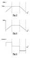
- FIG. 3is an example plot of voltage presented to the load of FIG. 2 versus time
- FIG. 4is an example plot of velocity of the seat of FIG. 2 versus time
- FIG. 5is an example plot of acceleration of the seat of FIG. 2 versus time.
- an embodiment of a monitoring system 10 for an electric motor 12may include a current monitoring portion 14 .
- the monitoring portion 14may be configured to determine the speed, movement, angular position and/or other parameters associated with the operation of the motor 12 as, for example, a function of the current circulating therethrough.
- the system 10may be used in any number of environments where motors facilitate movement of moveable objects.
- the motor 12may be configured to facilitate movement of a vehicle seat within a vehicle seat track and/or a window within a window track.
- vehicle occupantsmay control electrically positionable seats by controlling a seat positioning switch that communicates with a control module used to instruct and control operations of an electric motor.
- a common vehicle seat control functionrelates to controlling fore and aft positioning of the vehicle seat.
- the switchmay be moveable in a fore direction to instigate forward movement of the vehicle seat, and in an aft direction to instigate rearward movement of the vehicle seat.
- the vehicle seat trackmay include stops or other stroke limiting elements to prevent the fore and after movements beyond desired bounds of the seat track.
- the system 10 of FIG. 1may include first and second relays 18 , 20 to control current from a primary power source 22 .
- the first relay 18is connected to ground and the second relay 20 is connected to the primary power source 22 .
- the second relay 20is connected to ground and the first relay 18 is connected to the primary power source 22 .
- both of the relays 18 , 20are connected to ground. This controls the direction of current flow through the motor 12 and the corresponding movement of the vehicle seat.
- Other suitable control methodologiesmay also be used.
- the inertia generated during seat movementmay be sufficient to permit continued movement of the seat after the relays 18 , 20 are opened, and power to the motor 12 ceases.
- the motor 12may continue to rotate as the seat continues to so move.
- the motor 12may continue to generate current ripples after power to the motor 12 ceases.
- stops or other elementsmay be included to impede and/or prevent further movement of the seat, window, etc. These elements provide an obstruction of suitable strength such that the force imparted to the stop may cause the seat, window, etc. to rebound in the opposite direction. This rebounding may cause the circulating current to experience ripples associated with the direction of rebound.
- the current ripplesmay thus include a different sign from the ripples prior to the rebound due to the motor 12 rotating and current flowing in an opposite direction after the rebound.
- the ability to continue counting current ripples and other current related parameters after power cut-off and motor reboundmay be helpful in properly monitoring operation of the vehicle seat, window, or other element associated with the motor 12 . While such movement may correspond with relatively small angular rotations of the motor 12 , over time, each successive rotation, if not monitored and reported as described herein, may build on prior non-reported rotations such that it may become difficult to accurately determine the true positioning of the seat, window, etc.
- the monitoring element 14may include a bidirectional current sensor 30 to monitor and otherwise assess current under any number of motor operating conditions, including but not limited to those described above.
- the bi-directional current sensor 30may be connected to both sides of a shunt resistor 32 , or other element having properties sufficient to facilitate monitoring current circulating through the motor 12 . Connecting the bidirectional current sensor 30 in this manner, i.e., on both sides of the current regulator 32 , allows the current sensor 30 to sense circulating current in primary and secondary directions.
- current flowing to the motor 12 from the primary power source 22is considered to be current associated with the primary direction.
- Current resulting from continued rotation of the motor after the relays 18 , 20 are closedis considered to be current associated with the secondary direction.
- the sensed currentmay be normalized with a voltage offset in order to avoid saturation and to provide symmetric excursions for positive and negative current values.
- the normalized currentmay be output to a band pass filter 36 .
- the band pass filter 36may filter the current according to a desired frequency range associated with an expected speed range of the motor 12 .
- the filtered currentmay then be distributed to a ripple detector 38 .
- the ripple detector 38may be configured for counting current peaks within the current circulating through the motor 12 in either of the primary and secondary directions, which may then be used by a controller 40 for determining the angular positioning of the motor 12 .
- the controller 40may be configured to monitor and track ripples detected with the ripple detector 38 such that the controller 40 is able to track positioning of the vehicle seat, window, etc. as a function of the peaks counted over time.
- the ability to sense current in both the primary and secondary directions, i.e., before and after power is cut-off to the motor 12allows the ripple detector 38 to count ripples associated with travel in the fore and aft directions, ripples occurring after power cut-off, and ripples associated with rebound activities.
- the filtered currentin addition to being output to the ripple detector 38 , may be output to a direction detector 42 .
- the direction detector 42may be configured to determine a direction of an element moved by the motor 12 as a function of the current relative to the voltage offset. For example, if the motor 12 is moving in the fore direction, the current may be expected to be a first voltage level relative to movement in the aft direction.
- the direction detector 42may keep track of these current levels such that it is able to output directionality information that may be used by the processor 40 to coordinate directionality with the other processed parameters of the motor 12 .
- the sensed currentmay be directly distributed to the processor 40 over a current input 44 .
- the current input 44may be used to sense the actual strength (voltage) of the current. This information may be helpful in assessing motor operation in that the signal strength tends to increase when more force is required to move the seat, window, etc.
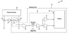
- an embodiment of a speed regulating system 45may include a microcontroller 46 (or field programmable array, etc.) and a DC/DC buck converter 48 .
- the microcontroller 46may output a command signal to the converter 48 that enables a controller 50 to switch a field effect transistor (FET) 52 .
- FETfield effect transistor
- the particular frequency at which the FET 52 is switchedmay depend on design and/or environmental considerations.
- multiple converters 48may be controlled by the microcontroller 46 . In other embodiments, any suitable power converter topology may be used.
- the FET 52If the FET 52 is switched on, current from a battery 54 flows through the FET 52 and an inductor 55 , and to a load 56 (provided the load 56 is electrically configured to receive current). A capacitor 58 charges as current flows to the load 56 . If the FET 52 is switched off, current will continue to flow through the inductor 55 creating a voltage potential that will draw current from a ground 60 and through a diode 62 . The voltage output by the converter 48 may be detected, in a known fashion, and fed back to the controller 50 .
- the load 56in the embodiment of FIG. 2 , includes motors 64 , 66 selectable via relays 68 , 70 , 72 .
- the load 56may take the form of that discussed with referenced to FIG. 1 .
- Other configurations, arrangements and/or loads 56are also possible.
- the load 56may include more than two motors, etc.
- the motors 64 , 66 of FIG. 2may be electrically connected with, for example, an adjustable automotive seat (or automotive window) 73 , etc.
- the relay 68selects which of the motors 64 , 66 may be activated. As illustrated, the motor 66 may be activated.
- the relays 70 , 72determine the direction of current flow to the selected motor. As illustrated, the relays 70 , 72 have grounded the motors 64 , 66 . If the relay 70 were toggled to its other position, current would flow in a clockwise direction through the motor 66 . If the relay 72 were toggled to its other position, current would flow in a counterclockwise direction through the motor 66 .
- the relays 68 , 70 , 72in the embodiment of FIG. 2 , are under the control of the microcontroller 46 in a known fashion.
- a shunt 74may be used to measure the current flow to/from the motors 64 , 66 .
- a ripple counting detection block 76such as the monitoring portion 14 illustrated in FIG. 1 or other suitable ripple counting arrangement, etc., may be used to determine for example, the speed, movement, angular position and/or other parameters associated with operation of the motors 64 , 66 based on the measured current. This information may be used by the microcontroller 46 to implement seat (window) memory functionality, etc., within an automotive vehicle. Alternatively, other current sensing technologies, such as a hall effect sensor, etc., may be used in concert with the microcontroller 46 to determine the seat (window) position.
- diodes 78 , 80e.g., Transil, Free-Wheeling, etc.
- varistor 88may be used to protect the circuitry and components of, for example, the load 56 . Any such suitable devices, however, may be used.
- FIG. 2may be contrasted with other configurations that (i) lack the controller 50 and include a capacitor instead of the diode 62 or (ii) lack the controller 50 and FET 52 (such that the battery 54 is directly electrically connected with the inductor 55 ) and include a switching element (such as a MOSFET) between the ground 60 and relay 72 , and a capacitor instead of the diode 62 .
- Speed control in such configurationsmay be achieved via pulse width modulation (PWM) control of the FET 52 in (i) or MOSFET in (ii) via the microcontroller 46 at frequencies up to 20 kHz. This PWM control attempts to regulate the effective voltage presented to the load 56 .
- PWMpulse width modulation
- Pulse-like voltage spikesmay occur at the beginning/end of the time period when the voltage is presented as the microcontroller 46 begins/ends its PWM control of the FET 52 in (i) or MOSFET in (ii). This PWM control may also alter the current waveform sensed by the shunt 74 and thus adversely affect ripple counting (as well as introduce electromagnetic noise into the system).
- the converter 48may present, under the command of the microcontroller 46 , a controllable/regulatable/selectable voltage to the load 56 that, inter alia, permits a soft start/soft stop of the motors 64 , 66 . That is, a voltage presented to the load 56 may ramp up to a desired value, continue at that desired value, and then ramp down to effectuate a soft start and soft stop of a selected motor.
- the profile of the voltage rampsas illustrated in FIG. 3 , are generally linear. In other embodiments, the voltage ramps may be convex, concave, etc. as dictated by the microcontroller 46 .
- the length of the soft start/soft stope.g., duration of the ramping, may, for example, be adjusted via RC circuitry in the controller 50 or by a command signal generated by the microcontroller 46 as apparent to those of ordinary skill.
- the converter 48may present a voltage to the load 56 approximately equal to a voltage of the battery 54 at the end of a soft start such that a selected motor is moving at a maximum speed after the soft start. In other embodiments, the converter 48 may present different voltages, relative to the voltage of the battery 54 , to the load 56 based on the control of the controller 50 by the microcontroller 46 .
- the velocity at which the seat (or window) 73 movesis proportional to the voltage presented to the load 56 .
- the voltage rampsare generally linear.
- the associated rate of speed increase and speed decreaseis generally linear as illustrated in FIG. 4 .
- the profile of the voltage rampsmay take any suitable shape as dictated by the microcontroller 46 . Differing voltage ramp profiles, however, may result in differing speed and acceleration plots as compared to those illustrated in FIGS. 4 and 5 .
- the FET 52may achieve relatively high switching frequencies, e.g., 100-300 kHz. These higher frequencies may improve the ripple detection by detection block 76 .
- the effects of the switching of the FET 52 on the current measured by the shunt 74may, for example, be filtered out using a low pass filter; electromagnetic noise associated with the switching of the FET 52 may be filtered out by the LC filter formed by the inductor 55 and capacitor 58 .
- the relay 68is configured to select which of the motors 64 , 66 to activate.
- the relays 70 , 72are configured to select the direction of current flow through the selected motor.
- the converter 48raises, at a controlled rate, a voltage presented to the load 56 up to a desired level (as directed by the microcontroller 46 ) and the selected motor begins to move.
- the detection block 76determines the number of motor turns associated with pulses produced by brushes of the selected motor. This information may later be used to facilitate memory functions associated with a position of the seat 73 . Once the seat 73 reaches a desired position, the converter 48 lowers, at a controlled rate, the voltage presented to the load 56 , and the relays 70 , 72 are grounded.
Landscapes
- Engineering & Computer Science (AREA)
- Aviation & Aerospace Engineering (AREA)
- Transportation (AREA)
- Mechanical Engineering (AREA)
- Control Of Direct Current Motors (AREA)
Abstract
Description
Claims (18)
Priority Applications (3)
| Application Number | Priority Date | Filing Date | Title |
|---|---|---|---|
| US12/411,480US8193746B2 (en) | 2008-05-23 | 2009-03-26 | Automotive electric motor speed control system |
| DE102009020842ADE102009020842B4 (en) | 2008-05-23 | 2009-05-12 | System for controlling the speed of an electric motor in a motor vehicle |
| CN200910202926.8ACN101585324B (en) | 2008-05-23 | 2009-05-22 | A motor vehicle electric motor speed control system |
Applications Claiming Priority (2)
| Application Number | Priority Date | Filing Date | Title |
|---|---|---|---|
| US5562308P | 2008-05-23 | 2008-05-23 | |
| US12/411,480US8193746B2 (en) | 2008-05-23 | 2009-03-26 | Automotive electric motor speed control system |
Publications (2)
| Publication Number | Publication Date |
|---|---|
| US20090289486A1 US20090289486A1 (en) | 2009-11-26 |
| US8193746B2true US8193746B2 (en) | 2012-06-05 |
Family
ID=41212762
Family Applications (1)
| Application Number | Title | Priority Date | Filing Date |
|---|---|---|---|
| US12/411,480Active2030-09-12US8193746B2 (en) | 2008-05-23 | 2009-03-26 | Automotive electric motor speed control system |
Country Status (3)
| Country | Link |
|---|---|
| US (1) | US8193746B2 (en) |
| CN (1) | CN101585324B (en) |
| DE (1) | DE102009020842B4 (en) |
Cited By (4)
| Publication number | Priority date | Publication date | Assignee | Title |
|---|---|---|---|---|
| US20130249576A1 (en)* | 2012-03-22 | 2013-09-26 | Hon Hai Precision Industry Co., Ltd. | Power supply unit testing system |
| US20170174102A1 (en)* | 2015-12-21 | 2017-06-22 | Hyundai Dymos Incorporated | Apparatus for controlled power seat of vehicle and method thereof |
| US10293711B2 (en)* | 2014-12-31 | 2019-05-21 | Hyundai Dymos Incorporated | Device and method for controlling vehicle seat |
| US20200017000A1 (en)* | 2018-07-12 | 2020-01-16 | Hyundai Motor Company | Vehicle and method for controlling the same |
Families Citing this family (13)
| Publication number | Priority date | Publication date | Assignee | Title |
|---|---|---|---|---|
| US8193746B2 (en) | 2008-05-23 | 2012-06-05 | Lear Corporation | Automotive electric motor speed control system |
| DE102011010194B4 (en)* | 2011-01-31 | 2014-05-15 | Keiper Gmbh & Co. Kg | Actuator for a vehicle seat |
| US9440525B1 (en)* | 2011-03-17 | 2016-09-13 | Kathleen K. Baty | Solar powered assisted trailer cooling system |
| US20130113455A1 (en)* | 2011-11-03 | 2013-05-09 | Chin-Tsung Lin | Power supply management apparatus and burglarproof power supply system that uses the power supply management apparatus |
| CN103245827A (en)* | 2012-02-01 | 2013-08-14 | 亚旭电子科技(江苏)有限公司 | Voltage and current measuring device |
| US20150180383A1 (en)* | 2012-07-27 | 2015-06-25 | Panasonic Intellectual Property Management Co., Ltd. | Air blower equipped with brushless dc motor |
| CN103684146B (en)* | 2012-09-11 | 2017-04-19 | 上海汽车集团股份有限公司 | Monitoring of running status of automobile seat motor |
| CN103786605B (en)* | 2012-10-31 | 2016-06-22 | 上海汽车集团股份有限公司 | The determination of automotive seat position and adjustment |
| CN103856125B (en)* | 2012-12-07 | 2016-08-03 | 上海汽车集团股份有限公司 | Automotive seat drives the suppression of noise in motor signal |
| JP6643862B2 (en)* | 2015-10-23 | 2020-02-12 | 株式会社ミツバ | Motor control device |
| DE102019132913A1 (en)* | 2018-12-06 | 2020-06-10 | Magna Closures Inc. | WAVE COUNTING FILTERING AND METHOD AND SYSTEM FOR DETECTING PEAK VALUES |
| FR3100492B1 (en)* | 2019-09-11 | 2021-11-05 | Faurecia Sieges Dautomobile | Motor vehicle seat safety device |
| CN112865665B (en)* | 2021-01-26 | 2022-12-02 | 大陆汽车电子(长春)有限公司 | Electronic control unit for driving an electric motor in a sensorless manner |
Citations (31)
| Publication number | Priority date | Publication date | Assignee | Title |
|---|---|---|---|---|
| GB2060944A (en) | 1979-10-12 | 1981-05-07 | Itt | Power-operated seat-adjusting apparatus for vehicles |
| US5514977A (en) | 1992-08-28 | 1996-05-07 | Linfinity Microelectronics, Inc. | Pulse detection and conditioning circuit |
| US5552683A (en) | 1993-02-23 | 1996-09-03 | Aerospatiale Societe Nationale Industrielle | Method of controlling a reversible electric device |
| US5798624A (en) | 1997-02-28 | 1998-08-25 | Lucas Industries | Motor circuit |
| US5818178A (en) | 1995-03-06 | 1998-10-06 | Hitachi, Ltd. | Valve control apparatus for an automobile |
| DE19634049C2 (en) | 1996-08-23 | 1999-09-02 | Temic Semiconductor Gmbh | Process for data acquisition |
| US5977732A (en) | 1997-02-04 | 1999-11-02 | Nissan Motor Co., Ltd. | Apparatus and method for determining presence or absence of foreign object or the like caught in power-open-and-closure mechanism |
| EP0997341A1 (en) | 1998-10-29 | 2000-05-03 | Aisin Seiki Kabushiki Kaisha | Control device for movable member |
| US6078154A (en) | 1999-02-12 | 2000-06-20 | Delco Electronics Corporation | Circuitry for determining actuator position |
| US6335600B1 (en) | 1999-09-07 | 2002-01-01 | Toyota Jidosha Kabushiki Kaisha | Motor drive unit and method of detecting malfunction of motor drive unit |
| US6380757B1 (en) | 2000-06-05 | 2002-04-30 | Delphi Technologies, Inc. | Start pulse rejection for a motor commutation pulse detection circuit |
| US6437533B1 (en) | 2001-08-08 | 2002-08-20 | Buehler Motor, Inc. | Actuator position control with inductive sensing |
| US6545439B2 (en) | 1998-10-27 | 2003-04-08 | Daimlerchrysler Ag | Method and circuit arrangement for detecting motion, direction and position of a part driven by an electric motor |
| US20030080699A1 (en)* | 2001-10-31 | 2003-05-01 | Rumney Timothy John | Power actuated seat |
| US6617816B2 (en) | 1999-12-27 | 2003-09-09 | Ricoh Company, Ltd. | DC motor rotation detecting apparatus and DC motor rotation control apparatus |
| US20040098213A1 (en) | 2001-05-30 | 2004-05-20 | Leopold Kostal Gmbh & Co. Kg | Method for determining the frequency of the current ripple in the armature current of a commutated DC motor |
| US20040107071A1 (en) | 2001-05-30 | 2004-06-03 | Leopold Kostal Gmbh & Co. Kg | Method for determining the rotational position of the drive shaft of a commutated DC motor |
| US20040111233A1 (en) | 2001-05-21 | 2004-06-10 | Leopold Kostal Gmbh & Co. Kg | Method for correcting the determination of the rotating position of a drive shaft of a commutated direct current motor |
| EP1453172A1 (en) | 2001-10-26 | 2004-09-01 | Lear Automotive (EEDS) Spain, S.L. | Method of detecting obstructions caused by electric windows and similar devices using current ripple |
| DE102004033129A1 (en) | 2003-07-30 | 2005-03-03 | Siemens Ag | Drive circuit, apparatus and method for noise suppression and use |
| US20050285551A1 (en)* | 2004-06-24 | 2005-12-29 | Lear Corporation | System and method for power seat motor control |
| DE69733141T2 (en) | 1996-10-04 | 2006-01-26 | C-Mac Invotronics Inc., Scaborough | Memory seat module with integrated sensors |
| US20060111144A1 (en) | 2004-11-25 | 2006-05-25 | Kabushiki Kaisha Toshiba | Communication apparatus and communication method |
| US7064509B1 (en) | 2005-03-14 | 2006-06-20 | Visteon Global Technologies, Inc. | Apparatus for DC motor position detection with capacitive ripple current extraction |
| US20060139179A1 (en)* | 2004-12-14 | 2006-06-29 | Kazutoshi Yamada | Anomaly judgment system for operator detection device and process for judging normality/anomaly of operator detection device |
| WO2006111144A1 (en) | 2005-04-20 | 2006-10-26 | Conti Temic Microelectronic Gmbh | Method for determining the position of a rotor of an electric motor without sensors |
| DE102005015658A1 (en) | 2005-04-06 | 2007-01-11 | Bayerische Motoren Werke Ag | Switching device for linking different electrical voltage levels in a motor vehicle |
| US7342369B2 (en) | 2006-02-17 | 2008-03-11 | Lear Corporation | Differential ripple detection method and system |
| US20090289486A1 (en) | 2008-05-23 | 2009-11-26 | Lear Corporation | Automotive electric motor speed control system |
| US20100027169A1 (en)* | 2008-07-30 | 2010-02-04 | Arnold Knott | Power distribution arrangement |
| US7723970B1 (en)* | 2005-10-03 | 2010-05-25 | Zilker Labs, Inc. | Method for pre-bias correction during turn-on of switching power regulators |
Family Cites Families (5)
| Publication number | Priority date | Publication date | Assignee | Title |
|---|---|---|---|---|
| JP3484001B2 (en) | 1995-09-29 | 2004-01-06 | 本田技研工業株式会社 | Motor control device |
| JP3147742B2 (en) | 1995-10-24 | 2001-03-19 | 三菱自動車工業株式会社 | Suspension device for vehicle seat |
| JP2007001366A (en)* | 2005-06-22 | 2007-01-11 | Tachibana Eletech Co Ltd | Power seat control device |
| US7126296B1 (en)* | 2005-06-30 | 2006-10-24 | Stmicroelectronics, Inc. | System and method for analog control of directional motors and other loads |
| CN1945956A (en)* | 2006-10-27 | 2007-04-11 | 陈加杰 | Low voltage AC soft starting method |
- 2009
- 2009-03-26USUS12/411,480patent/US8193746B2/enactiveActive
- 2009-05-12DEDE102009020842Apatent/DE102009020842B4/ennot_activeExpired - Fee Related
- 2009-05-22CNCN200910202926.8Apatent/CN101585324B/ennot_activeExpired - Fee Related
Patent Citations (35)
| Publication number | Priority date | Publication date | Assignee | Title |
|---|---|---|---|---|
| GB2060944A (en) | 1979-10-12 | 1981-05-07 | Itt | Power-operated seat-adjusting apparatus for vehicles |
| US5514977A (en) | 1992-08-28 | 1996-05-07 | Linfinity Microelectronics, Inc. | Pulse detection and conditioning circuit |
| US5552683A (en) | 1993-02-23 | 1996-09-03 | Aerospatiale Societe Nationale Industrielle | Method of controlling a reversible electric device |
| US5818178A (en) | 1995-03-06 | 1998-10-06 | Hitachi, Ltd. | Valve control apparatus for an automobile |
| DE19634049C2 (en) | 1996-08-23 | 1999-09-02 | Temic Semiconductor Gmbh | Process for data acquisition |
| DE69733141T2 (en) | 1996-10-04 | 2006-01-26 | C-Mac Invotronics Inc., Scaborough | Memory seat module with integrated sensors |
| US5977732A (en) | 1997-02-04 | 1999-11-02 | Nissan Motor Co., Ltd. | Apparatus and method for determining presence or absence of foreign object or the like caught in power-open-and-closure mechanism |
| US5798624A (en) | 1997-02-28 | 1998-08-25 | Lucas Industries | Motor circuit |
| US6545439B2 (en) | 1998-10-27 | 2003-04-08 | Daimlerchrysler Ag | Method and circuit arrangement for detecting motion, direction and position of a part driven by an electric motor |
| EP0997341A1 (en) | 1998-10-29 | 2000-05-03 | Aisin Seiki Kabushiki Kaisha | Control device for movable member |
| EP0997341B1 (en) | 1998-10-29 | 2005-09-28 | Aisin Seiki Kabushiki Kaisha | Control device for movable member |
| US6078154A (en) | 1999-02-12 | 2000-06-20 | Delco Electronics Corporation | Circuitry for determining actuator position |
| US6335600B1 (en) | 1999-09-07 | 2002-01-01 | Toyota Jidosha Kabushiki Kaisha | Motor drive unit and method of detecting malfunction of motor drive unit |
| US6617816B2 (en) | 1999-12-27 | 2003-09-09 | Ricoh Company, Ltd. | DC motor rotation detecting apparatus and DC motor rotation control apparatus |
| US6380757B1 (en) | 2000-06-05 | 2002-04-30 | Delphi Technologies, Inc. | Start pulse rejection for a motor commutation pulse detection circuit |
| US20040111233A1 (en) | 2001-05-21 | 2004-06-10 | Leopold Kostal Gmbh & Co. Kg | Method for correcting the determination of the rotating position of a drive shaft of a commutated direct current motor |
| US20040107071A1 (en) | 2001-05-30 | 2004-06-03 | Leopold Kostal Gmbh & Co. Kg | Method for determining the rotational position of the drive shaft of a commutated DC motor |
| US20040098213A1 (en) | 2001-05-30 | 2004-05-20 | Leopold Kostal Gmbh & Co. Kg | Method for determining the frequency of the current ripple in the armature current of a commutated DC motor |
| US6437533B1 (en) | 2001-08-08 | 2002-08-20 | Buehler Motor, Inc. | Actuator position control with inductive sensing |
| EP1453172A1 (en) | 2001-10-26 | 2004-09-01 | Lear Automotive (EEDS) Spain, S.L. | Method of detecting obstructions caused by electric windows and similar devices using current ripple |
| US6949904B2 (en)* | 2001-10-31 | 2005-09-27 | Muirhead Aerospace Ltd. | Power actuated seat |
| US20030080699A1 (en)* | 2001-10-31 | 2003-05-01 | Rumney Timothy John | Power actuated seat |
| DE102004033129A1 (en) | 2003-07-30 | 2005-03-03 | Siemens Ag | Drive circuit, apparatus and method for noise suppression and use |
| US7064506B2 (en)* | 2004-06-24 | 2006-06-20 | Lear Corporation | System and method for power seat motor control |
| US20050285551A1 (en)* | 2004-06-24 | 2005-12-29 | Lear Corporation | System and method for power seat motor control |
| US20060111144A1 (en) | 2004-11-25 | 2006-05-25 | Kabushiki Kaisha Toshiba | Communication apparatus and communication method |
| US20060139179A1 (en)* | 2004-12-14 | 2006-06-29 | Kazutoshi Yamada | Anomaly judgment system for operator detection device and process for judging normality/anomaly of operator detection device |
| US7064509B1 (en) | 2005-03-14 | 2006-06-20 | Visteon Global Technologies, Inc. | Apparatus for DC motor position detection with capacitive ripple current extraction |
| DE102005015658A1 (en) | 2005-04-06 | 2007-01-11 | Bayerische Motoren Werke Ag | Switching device for linking different electrical voltage levels in a motor vehicle |
| WO2006111144A1 (en) | 2005-04-20 | 2006-10-26 | Conti Temic Microelectronic Gmbh | Method for determining the position of a rotor of an electric motor without sensors |
| US7723970B1 (en)* | 2005-10-03 | 2010-05-25 | Zilker Labs, Inc. | Method for pre-bias correction during turn-on of switching power regulators |
| US20100213914A1 (en)* | 2005-10-03 | 2010-08-26 | Fernald Kenneth W | Correcting pre-bias during turn-on of switching power regulators |
| US7342369B2 (en) | 2006-02-17 | 2008-03-11 | Lear Corporation | Differential ripple detection method and system |
| US20090289486A1 (en) | 2008-05-23 | 2009-11-26 | Lear Corporation | Automotive electric motor speed control system |
| US20100027169A1 (en)* | 2008-07-30 | 2010-02-04 | Arnold Knott | Power distribution arrangement |
Non-Patent Citations (1)
| Title |
|---|
| Office Action dated Jan. 11, 2010 from corresponding German Application No. 10 2009 020 842.9. |
Cited By (7)
| Publication number | Priority date | Publication date | Assignee | Title |
|---|---|---|---|---|
| US20130249576A1 (en)* | 2012-03-22 | 2013-09-26 | Hon Hai Precision Industry Co., Ltd. | Power supply unit testing system |
| US9404979B2 (en)* | 2012-03-22 | 2016-08-02 | Shenzhen Goldsun Network Intelligence Technology Co., Ltd. | Power supply unit testing system |
| US10293711B2 (en)* | 2014-12-31 | 2019-05-21 | Hyundai Dymos Incorporated | Device and method for controlling vehicle seat |
| US20170174102A1 (en)* | 2015-12-21 | 2017-06-22 | Hyundai Dymos Incorporated | Apparatus for controlled power seat of vehicle and method thereof |
| US9975453B2 (en)* | 2015-12-21 | 2018-05-22 | Hyundai Dymos Incorporated | Apparatus for controlled power seat of vehicle and method thereof |
| US20200017000A1 (en)* | 2018-07-12 | 2020-01-16 | Hyundai Motor Company | Vehicle and method for controlling the same |
| US10926670B2 (en)* | 2018-07-12 | 2021-02-23 | Hyundai Motor Company | Vehicle and method for controlling the same |
Also Published As
| Publication number | Publication date |
|---|---|
| DE102009020842B4 (en) | 2010-11-04 |
| CN101585324A (en) | 2009-11-25 |
| CN101585324B (en) | 2013-02-20 |
| DE102009020842A1 (en) | 2009-11-26 |
| US20090289486A1 (en) | 2009-11-26 |
Similar Documents
| Publication | Publication Date | Title |
|---|---|---|
| US8193746B2 (en) | Automotive electric motor speed control system | |
| US7342370B2 (en) | Electronic control system with torque and/or speed boost for motor vehicle seats | |
| US10122303B2 (en) | Motor control device | |
| US7479749B2 (en) | Vehicle seat arrangement with an electric adjustment mechanism | |
| JP3547523B2 (en) | Intelligent commutation pulse detection system for controlling DC motors used in automotive accessories | |
| US20090015980A1 (en) | Solenoid valve driving circuit and solenoid valve | |
| US7701157B2 (en) | Motor controller and method for controlling motor | |
| US8084978B2 (en) | Adjusting device and control device of a vehicle | |
| US8690252B2 (en) | Headrest position adjusting device and headrest position adjusting method | |
| US8498090B2 (en) | Apparatus and method for supplying power to a voltage- or current-releasing switching device | |
| US10730406B2 (en) | Electronic control system for a vehicle seat | |
| CN108880362A (en) | Control device, Optical devices, control method and storage medium | |
| EP0848490B1 (en) | Adjustable motor control circuit for power windows | |
| CN109311414B (en) | Electric seat system and motor reverse rotation sensing method thereof | |
| JP5864773B2 (en) | Method and apparatus for controlling at least one actuating element for occupant protection means | |
| JP2014007805A (en) | Device for controlling speed of dc motor | |
| US11660938B2 (en) | Shading device | |
| KR101072809B1 (en) | Apparatus for controlling solenoid coil in vehicle | |
| JP5422292B2 (en) | Vehicle seat belt retractor control device | |
| CN111817621B (en) | Method for determining the movement of a rotor | |
| US20070182352A1 (en) | Method and circuit arrangement for the electrical control and/or regulation of the movement of an electrically driven unit | |
| CN111466060B (en) | Method for at least partially cancelling oscillations for an H-bridge and related assembly | |
| JP2020075612A (en) | Seat belt retractor and seat belt device | |
| GB2357163A (en) | Electric motor power control device | |
| EP3098115A1 (en) | A method and control unit for automatic controlling an electrical energy supply to an electrical dc motor of a drive unit of a rotatable vehicle mirror module |
Legal Events
| Date | Code | Title | Description |
|---|---|---|---|
| AS | Assignment | Owner name:LEAR CORPORATION, MICHIGAN Free format text:ASSIGNMENT OF ASSIGNORS INTEREST;ASSIGNORS:JIMENEZ PINO, RAFAEL;CASTILLA, JUAN LUIS;REEL/FRAME:022453/0674 Effective date:20090320 | |
| AS | Assignment | Owner name:JPMORGAN CHASE BANK, N.A., AS ADMINISTRATIVE AGENT Free format text:GRANT OF FIRST LIEN SECURITY INTEREST IN PATENT RIGHTS;ASSIGNOR:LEAR CORPORATION;REEL/FRAME:023519/0267 Effective date:20091109 Owner name:JPMORGAN CHASE BANK, N.A., AS ADMINISTRATIVE AGENT Free format text:GRANT OF SECOND LIEN SECURITY INTEREST IN PATENT RIGHTS;ASSIGNOR:LEAR CORPORATION;REEL/FRAME:023519/0626 Effective date:20091109 | |
| STCF | Information on status: patent grant | Free format text:PATENTED CASE | |
| AS | Assignment | Owner name:JPMORGAN CAHSE BANK, N.A., AS AGENT, ILLINOIS Free format text:SECURITY INTEREST;ASSIGNOR:LEAR CORPORATION;REEL/FRAME:030076/0016 Effective date:20130130 Owner name:JPMORGAN CHASE BANK, N.A., AS AGENT, ILLINOIS Free format text:SECURITY INTEREST;ASSIGNOR:LEAR CORPORATION;REEL/FRAME:030076/0016 Effective date:20130130 | |
| AS | Assignment | Owner name:LEAR CORPORATION, MICHIGAN Free format text:RELEASE BY SECURED PARTY;ASSIGNOR:JPMORGAN CHASE BANK, N.A.;REEL/FRAME:032770/0843 Effective date:20100830 | |
| FPAY | Fee payment | Year of fee payment:4 | |
| AS | Assignment | Owner name:LEAR CORPORATION, MICHIGAN Free format text:RELEASE BY SECURED PARTY;ASSIGNOR:JPMORGAN CHASE BANK, N.A., AS AGENT;REEL/FRAME:037701/0180 Effective date:20160104 Owner name:LEAR CORPORATION, MICHIGAN Free format text:RELEASE BY SECURED PARTY;ASSIGNOR:JPMORGAN CHASE BANK, N.A., AS AGENT;REEL/FRAME:037701/0340 Effective date:20160104 Owner name:LEAR CORPORATION, MICHIGAN Free format text:RELEASE BY SECURED PARTY;ASSIGNOR:JPMORGAN CHASE BANK, N.A., AS AGENT;REEL/FRAME:037701/0251 Effective date:20160104 | |
| AS | Assignment | Owner name:LEAR CORPORATION, MICHIGAN Free format text:RELEASE BY SECURED PARTY;ASSIGNOR:JPMORGAN CHASE BANK, N.A., AS AGENT;REEL/FRAME:037702/0911 Effective date:20160104 | |
| MAFP | Maintenance fee payment | Free format text:PAYMENT OF MAINTENANCE FEE, 8TH YEAR, LARGE ENTITY (ORIGINAL EVENT CODE: M1552); ENTITY STATUS OF PATENT OWNER: LARGE ENTITY Year of fee payment:8 | |
| MAFP | Maintenance fee payment | Free format text:PAYMENT OF MAINTENANCE FEE, 12TH YEAR, LARGE ENTITY (ORIGINAL EVENT CODE: M1553); ENTITY STATUS OF PATENT OWNER: LARGE ENTITY Year of fee payment:12 |