US8192472B2 - Fracture fixation plate for the coronoid of the proximal ulna - Google Patents
Fracture fixation plate for the coronoid of the proximal ulnaDownload PDFInfo
- Publication number
- US8192472B2 US8192472B2US12/261,456US26145608AUS8192472B2US 8192472 B2US8192472 B2US 8192472B2US 26145608 AUS26145608 AUS 26145608AUS 8192472 B2US8192472 B2US 8192472B2
- Authority
- US
- United States
- Prior art keywords
- arm
- bone
- plate
- ring
- central ring
- Prior art date
- Legal status (The legal status is an assumption and is not a legal conclusion. Google has not performed a legal analysis and makes no representation as to the accuracy of the status listed.)
- Active, expires
Links
Images


Classifications
- A—HUMAN NECESSITIES
- A61—MEDICAL OR VETERINARY SCIENCE; HYGIENE
- A61B—DIAGNOSIS; SURGERY; IDENTIFICATION
- A61B17/00—Surgical instruments, devices or methods
- A61B17/56—Surgical instruments or methods for treatment of bones or joints; Devices specially adapted therefor
- A61B17/58—Surgical instruments or methods for treatment of bones or joints; Devices specially adapted therefor for osteosynthesis, e.g. bone plates, screws or setting implements
- A61B17/68—Internal fixation devices, including fasteners and spinal fixators, even if a part thereof projects from the skin
- A61B17/80—Cortical plates, i.e. bone plates; Instruments for holding or positioning cortical plates, or for compressing bones attached to cortical plates
- A—HUMAN NECESSITIES
- A61—MEDICAL OR VETERINARY SCIENCE; HYGIENE
- A61B—DIAGNOSIS; SURGERY; IDENTIFICATION
- A61B17/00—Surgical instruments, devices or methods
- A61B17/16—Instruments for performing osteoclasis; Drills or chisels for bones; Trepans
- A61B17/17—Guides or aligning means for drills, mills, pins or wires
- A61B17/1739—Guides or aligning means for drills, mills, pins or wires specially adapted for particular parts of the body
- A—HUMAN NECESSITIES
- A61—MEDICAL OR VETERINARY SCIENCE; HYGIENE
- A61B—DIAGNOSIS; SURGERY; IDENTIFICATION
- A61B17/00—Surgical instruments, devices or methods
- A61B17/56—Surgical instruments or methods for treatment of bones or joints; Devices specially adapted therefor
- A61B17/58—Surgical instruments or methods for treatment of bones or joints; Devices specially adapted therefor for osteosynthesis, e.g. bone plates, screws or setting implements
- A61B17/68—Internal fixation devices, including fasteners and spinal fixators, even if a part thereof projects from the skin
- A61B17/80—Cortical plates, i.e. bone plates; Instruments for holding or positioning cortical plates, or for compressing bones attached to cortical plates
- A61B17/8033—Cortical plates, i.e. bone plates; Instruments for holding or positioning cortical plates, or for compressing bones attached to cortical plates having indirect contact with screw heads, or having contact with screw heads maintained with the aid of additional components, e.g. nuts, wedges or head covers
- A61B17/8047—Cortical plates, i.e. bone plates; Instruments for holding or positioning cortical plates, or for compressing bones attached to cortical plates having indirect contact with screw heads, or having contact with screw heads maintained with the aid of additional components, e.g. nuts, wedges or head covers wherein the additional element surrounds the screw head in the plate hole
- A—HUMAN NECESSITIES
- A61—MEDICAL OR VETERINARY SCIENCE; HYGIENE
- A61B—DIAGNOSIS; SURGERY; IDENTIFICATION
- A61B17/00—Surgical instruments, devices or methods
- A61B17/56—Surgical instruments or methods for treatment of bones or joints; Devices specially adapted therefor
- A61B17/58—Surgical instruments or methods for treatment of bones or joints; Devices specially adapted therefor for osteosynthesis, e.g. bone plates, screws or setting implements
- A61B17/68—Internal fixation devices, including fasteners and spinal fixators, even if a part thereof projects from the skin
- A61B17/80—Cortical plates, i.e. bone plates; Instruments for holding or positioning cortical plates, or for compressing bones attached to cortical plates
- A61B17/8061—Cortical plates, i.e. bone plates; Instruments for holding or positioning cortical plates, or for compressing bones attached to cortical plates specially adapted for particular bones
- A—HUMAN NECESSITIES
- A61—MEDICAL OR VETERINARY SCIENCE; HYGIENE
- A61B—DIAGNOSIS; SURGERY; IDENTIFICATION
- A61B17/00—Surgical instruments, devices or methods
- A61B17/56—Surgical instruments or methods for treatment of bones or joints; Devices specially adapted therefor
- A61B17/58—Surgical instruments or methods for treatment of bones or joints; Devices specially adapted therefor for osteosynthesis, e.g. bone plates, screws or setting implements
- A61B17/68—Internal fixation devices, including fasteners and spinal fixators, even if a part thereof projects from the skin
- A61B17/80—Cortical plates, i.e. bone plates; Instruments for holding or positioning cortical plates, or for compressing bones attached to cortical plates
- A61B17/8085—Cortical plates, i.e. bone plates; Instruments for holding or positioning cortical plates, or for compressing bones attached to cortical plates with pliable or malleable elements or having a mesh-like structure, e.g. small strips
- A—HUMAN NECESSITIES
- A61—MEDICAL OR VETERINARY SCIENCE; HYGIENE
- A61B—DIAGNOSIS; SURGERY; IDENTIFICATION
- A61B17/00—Surgical instruments, devices or methods
- A61B17/56—Surgical instruments or methods for treatment of bones or joints; Devices specially adapted therefor
- A61B17/58—Surgical instruments or methods for treatment of bones or joints; Devices specially adapted therefor for osteosynthesis, e.g. bone plates, screws or setting implements
- A61B17/88—Osteosynthesis instruments; Methods or means for implanting or extracting internal or external fixation devices
- A61B17/8863—Apparatus for shaping or cutting osteosynthesis equipment by medical personnel
- B—PERFORMING OPERATIONS; TRANSPORTING
- B25—HAND TOOLS; PORTABLE POWER-DRIVEN TOOLS; MANIPULATORS
- B25B—TOOLS OR BENCH DEVICES NOT OTHERWISE PROVIDED FOR, FOR FASTENING, CONNECTING, DISENGAGING OR HOLDING
- B25B27/00—Hand tools, specially adapted for fitting together or separating parts or objects whether or not involving some deformation, not otherwise provided for
- B25B27/02—Hand tools, specially adapted for fitting together or separating parts or objects whether or not involving some deformation, not otherwise provided for for connecting objects by press fit or detaching same
- B25B27/026—Hand tools, specially adapted for fitting together or separating parts or objects whether or not involving some deformation, not otherwise provided for for connecting objects by press fit or detaching same fluid driven
- B—PERFORMING OPERATIONS; TRANSPORTING
- B25—HAND TOOLS; PORTABLE POWER-DRIVEN TOOLS; MANIPULATORS
- B25B—TOOLS OR BENCH DEVICES NOT OTHERWISE PROVIDED FOR, FOR FASTENING, CONNECTING, DISENGAGING OR HOLDING
- B25B27/00—Hand tools, specially adapted for fitting together or separating parts or objects whether or not involving some deformation, not otherwise provided for
- B25B27/02—Hand tools, specially adapted for fitting together or separating parts or objects whether or not involving some deformation, not otherwise provided for for connecting objects by press fit or detaching same
- B25B27/06—Hand tools, specially adapted for fitting together or separating parts or objects whether or not involving some deformation, not otherwise provided for for connecting objects by press fit or detaching same inserting or withdrawing sleeves or bearing races
- B25B27/064—Hand tools, specially adapted for fitting together or separating parts or objects whether or not involving some deformation, not otherwise provided for for connecting objects by press fit or detaching same inserting or withdrawing sleeves or bearing races fluid driven
- A—HUMAN NECESSITIES
- A61—MEDICAL OR VETERINARY SCIENCE; HYGIENE
- A61B—DIAGNOSIS; SURGERY; IDENTIFICATION
- A61B17/00—Surgical instruments, devices or methods
- A61B17/16—Instruments for performing osteoclasis; Drills or chisels for bones; Trepans
- A61B17/17—Guides or aligning means for drills, mills, pins or wires
- A61B17/1728—Guides or aligning means for drills, mills, pins or wires for holes for bone plates or plate screws
- A—HUMAN NECESSITIES
- A61—MEDICAL OR VETERINARY SCIENCE; HYGIENE
- A61B—DIAGNOSIS; SURGERY; IDENTIFICATION
- A61B17/00—Surgical instruments, devices or methods
- A61B17/56—Surgical instruments or methods for treatment of bones or joints; Devices specially adapted therefor
- A61B17/58—Surgical instruments or methods for treatment of bones or joints; Devices specially adapted therefor for osteosynthesis, e.g. bone plates, screws or setting implements
- A61B17/68—Internal fixation devices, including fasteners and spinal fixators, even if a part thereof projects from the skin
- A61B17/80—Cortical plates, i.e. bone plates; Instruments for holding or positioning cortical plates, or for compressing bones attached to cortical plates
- A61B17/809—Cortical plates, i.e. bone plates; Instruments for holding or positioning cortical plates, or for compressing bones attached to cortical plates with bone-penetrating elements, e.g. blades or prongs
- A—HUMAN NECESSITIES
- A61—MEDICAL OR VETERINARY SCIENCE; HYGIENE
- A61B—DIAGNOSIS; SURGERY; IDENTIFICATION
- A61B17/00—Surgical instruments, devices or methods
- A61B17/56—Surgical instruments or methods for treatment of bones or joints; Devices specially adapted therefor
- A61B17/58—Surgical instruments or methods for treatment of bones or joints; Devices specially adapted therefor for osteosynthesis, e.g. bone plates, screws or setting implements
- A61B17/68—Internal fixation devices, including fasteners and spinal fixators, even if a part thereof projects from the skin
- A61B17/84—Fasteners therefor or fasteners being internal fixation devices
- A61B17/86—Pins or screws or threaded wires; nuts therefor
- A61B17/864—Pins or screws or threaded wires; nuts therefor hollow, e.g. with socket or cannulated
- Y—GENERAL TAGGING OF NEW TECHNOLOGICAL DEVELOPMENTS; GENERAL TAGGING OF CROSS-SECTIONAL TECHNOLOGIES SPANNING OVER SEVERAL SECTIONS OF THE IPC; TECHNICAL SUBJECTS COVERED BY FORMER USPC CROSS-REFERENCE ART COLLECTIONS [XRACs] AND DIGESTS
- Y10—TECHNICAL SUBJECTS COVERED BY FORMER USPC
- Y10S—TECHNICAL SUBJECTS COVERED BY FORMER USPC CROSS-REFERENCE ART COLLECTIONS [XRACs] AND DIGESTS
- Y10S606/00—Surgery
- Y10S606/902—Cortical plate specifically adapted for a particular bone
Definitions
- the subject matter of this disclosurerelates broadly to surgical devices and methods for the internal fixation of fractured bones, and more particularly, to bone plates and fasteners.
- elbow fracturesaccount for only about 5-8% of all fractures and occur most commonly in older people as a result of a fall.
- the functional outcomes of elbow fracturesoften include high rates of joint stiffness, loss of range of motion and non-union.
- a bone plate attached to the surface of a fractured bone of the elbow jointmay tend to stand “proud” of the bone surface.
- Currently available platesdo not fit well on the bone surfaces without impinging on soft tissue or obstructing the natural articulation of the joint.
- Fractures of the coronoidwhich is located on the proximal ulna, are typically small but difficult to treat. Proper treatment is important since the coronoid fracture may have a heavy impact on overall elbow stability. Traditional fixation of these fractures involve capture of the coronoid fragments with screws or sutures coming from the posterior side of the ulna. This type of fixation may not be stable enough to resist the strong anterior dislocating force of the distal humerus.
- the olecranonis located on the posterior side of the proximal end of the ulna and articulates in the olecranon fossa.
- the olecranonis not covered with thick layers of soft tissue and is particularly vulnerable to external impacts and fracture.
- the olecranonalso is the attachment location of the triceps muscle used in extension of the arm, and transfers very high forces.
- the surgeonmay intentionally sever the olecranon from the proximal ulna during an osteotomy procedure in order to reflect the triceps muscle, thereby obtaining improved surgical access to the distal humerus. Once the repair to the humerus has been completed, the surgeon then may use a bone plate to reattach the olecranon to the proximal ulna.
- a system of bendable platesis provided that may be easily and safely reconfigured inside the patient's body (in situ) during the surgical procedure.
- the systemcan be reconfigured without distorting the shape of bone fastener holes in the plate, and any threads within the holes.
- the systemincludes and is adapted for use with in situ bending tools to reconfigure the plate inside the patient's body during the surgical procedure.
- a system of low profile bone plates and fastenersare provided for the internal fixation of the fractured bones of the elbow.
- the elbow jointis not protected with thick layers of soft tissue.
- the plates of the system of the inventionhave minimal thickness and conform closely to the bone surface.
- a “proud” fastener headmay lead to soft tissue irritation, inflammation or other types of trauma that may cause complications and patient discomfort.
- An elbow fracture fixation systemis provided that also includes locking fasteners for attachment of the bone plate to the fractured bone.
- the primary functions of various bone plates of the systeminclude not only holding the bone fragments together in healing alignment, but also the transfer of forces from the metaphysis to the diaphysis of the fractured bone while the bone is mending.
- the systemallows the distal tip of a fastener to be anchored into healthy, cortical bone, and the transfer of force from the healthy bone to the plate, such that the plate properly accomplishes load sharing.
- a system for elbow fixationincludes a number of locking fasteners, each having an optimal trajectory, directly beneath the articulation surface of the fractured bone to create a scaffold for transferring forces from the articulating surface to the bone plate.
- a system for the internal fixation of a fractured bone of an elbow joint of a patienthas at least one bone plate, each bone plate having a plurality of holes and configured to fit an anatomical surface of the fractured bone.
- the systemalso has a plurality of fasteners including at least one locking fastener for attaching the bone plate to the bone.
- At least one of the holesis a threaded hole and the locking fastener can lock into the threaded hole.
- the locking fastenermay be a fixed-angle locking fastener or a multidirectional locking fastener.
- the systemmay also have at least one non-locking fastener and the threaded hole can receive the non-locking fastener.
- the non-locking fastenermay be a multidirectional compression fastener.
- the bone platemay also have a plurality of threaded holes and a plurality of drill guides. Each drill guide has a bore sized for guiding a drill and a proximal portion that is engageable with a tool for removal of the drill guide from the threaded hole. Each drill guide is removably preassembled into one of the plurality of threaded holes.
- the systemalso may have a first bending tool and a second bending tool.
- Each bending toolhas an elongated rod having a handle and an end effector at one end of the elongated rod and adapted for removable engagement to the drill guide.
- a usermay removably attach the first bending tool to one of the drill guides and the second bending tool to another of the drill guides and then simultaneously apply a leveraging force to each of the first and second bending tools, thereby reconfiguring the bone plate.
- the bone plate of the systemmay be at least one of a radial plate for fixation of the proximal radius bone, an olecranon plate for fixation of the olecranon of the proximal ulna bone, a coronoid plate for fixation of the coronoid process of the proximal ulna bone, a lateral plate for fixation of the lateral distal humerus bone, a medial plate for fixation of the medial distal humerus bone, and a posterolateral plate for fixation of the posterolateral distal humerus bone.
- a bone plate for the proximal radiushas a rigid body with proximal and distal ends defining a longitudinal axis, a medial edge and a lateral edge.
- the bone platealso has a first arm extending from the rigid body.
- the first armhas a first ring element attached to the body by a first curved bendable bridge element.
- the rigid bodyhas a central hole and the first ring element includes a first hole.
- Each of the central and first holescan receive a fastener for attaching the bone plate to the bone.
- the central holemay be threaded and define a central axis
- the first holemay be threaded and define a first thread axis.
- the first armmay extend from the rigid body proximal-medially, and the first curved bendable bridge may be attached to the medial edge of the rigid body.
- the bone platemay also have a second arm extending proximal-laterally from the rigid body and including a second ring element attached to the lateral edge of the rigid body by a second curved bendable bridge element, the second ring element including a second hole having a thread that defines a second thread axis.
- the bone platemay also have a third arm extending proximally from the rigid body and including a third ring element attached to the proximal end of the rigid body by a third bridge element, the third ring element including a third threaded hole defining a third thread axis.
- the first, second and third armsform a fork-like structure and the first, second and third thread axes converge but do not intersect.
- the bone platemay also have a fourth arm extending distally from the rigid body.
- the fourth armmay have a fourth ring element attached to the distal end of the rigid body, the fourth ring element having a fourth threaded hole defining a fourth thread axis.
- the bone platemay also have a first, a second, a third and a central drill guide preassembled into the first, second, third and central holes, respectively.
- Each of the first curved, second curved and third bendable bridge elementsis less stiff than the rigid body, but together preferably have a combined stiffness that approximates the stiffness of the rigid body.
- Each of the first, second and third drill guidesis adapted for application of a bending tool, such that a user may use a pair of bending tools to apply a leveraging force to reconfigure any one of the first, second and third arms.
- the bone platemay also have a fifth arm extending distally from the fourth ring element.
- the fifth armmay have a fifth ring element attached to the distal end of the rigid body by a fifth bendable bridge element.
- the fifth ring elementmay have a fifth threaded hole for receiving a fastener, and have a fifth drill guide preassembled into the fifth hole.
- Each of the fourth and fifth bendable bridge elementsis less stiff than the rigid body, and each of the fourth and fifth drill guides is adapted for application of a bending tool, such that a user may use a pair of bending tools to apply a leveraging force to reconfigure either of the fourth and fifth arms.
- the fourth and fifth bendable bridge elementsmay also be fragmentable, such that a user may use the pair of bending tools to apply a leveraging force to fatigue fracture the fourth bendable bridge element in order to remove the fourth and fifth arms, and to apply a leveraging force to fatigue fracture the fifth bendable bridge in order to remove the fifth arm.
- bone plates for the lateral and medial surfaces of the distal humeruseach have a rigid body portion with substantially the same thickness.
- the rigid portion of each of the medial and lateral plateshas a distal end, a proximal end, a top surface, a bottom surface, a medial edge and an opposing lateral edge.
- the platesalso have a plurality of holes extending between the top and bottom surfaces, each of the holes for receiving a fastener for attachment of the bone plate to the bone.
- the lateral bone platealso has at least one positioning foot extending from an edge downwardly towards the bone surface to aid in the positioning of the bone plate on the bone surface.
- the bone platesmay also each have a first segment attached to the distal end of the rigid body portion by a first bendable bridge element that is longitudinally aligned along one of the medial and lateral edges of the rigid body portion, and the first segment includes a threaded hole for receiving one of the fasteners.
- the bone platesmay each also have a proximal edge of the first segment, and the proximal edge and the distal end of the rigid body are spaced apart and define a gap, and the gap includes a throat opening adjacent to the first bendable bridge element and is configured for guiding a K-wire passed therethrough.
- the bone platesmay also each have a second segment attached to the distal edge of the first segment by a second bendable bridge element that is longitudinally aligned with the first bendable bridge element, and the second segment includes a threaded hole for receiving one of the fasteners.
- the bone platesmay also each have one or more elongated slot for receiving a compression fastener, and the length of the slot is greater than the width of the slot and the length is oriented in the longitudinal direction of the respective bone plate.
- the lateral plateincludes recesses at the bottom surface of the plate on at least one side, and preferably both sides, of the elongated slot to permit clearance for screw angulation toward the center of the bone for improved purchase of the screws.
- the thickness of the rigid body portion on respective medial side and lateral sides of the slotsmay also be thinner than the average thickness of the rigid body portion for each of the medial and lateral plates.
- the bone platesmay also each have an hourglass-shaped opening extending between the top and bottom surfaces, and the hourglass-shaped opening has two ends, each of which are configured to guide a K-wire passed therethrough.
- the proximal end of each of the bone platesmay also be tapered.
- the thickness of the first bridge elementmay also be less than the thickness of the rigid body portion.
- the bone platemay each also have a distal threaded hole near the distal end of the rigid body, a distal tall drill guide preassembled into the distal threaded hole, and a first tall drill guide preassembled into the first threaded hole.
- the distal and first tall drill guidesmay be adapted for application of a bending tool, such that a user may use a pair of bending tools to apply a leveraging force to reconfigure the first bendable bridge, thereby repositioning the first segment to a desired orientation with respect to the bone.
- the bone platemay each also have a plurality of proximal threaded holes located in the rigid body portion near the proximal end, and a like plurality of short drill guides, and each of the proximal threaded holes is preassembled with one of the short drill guides.
- a bone plate for the posterolateral surface of the distal humerushas a body with a thickness substantially greater than the medial plate (greater than fifty percent thicker).
- the bodyhas a proximal end, a distal end and a curvilinear, longitudinal axis extending therebetween.
- a first arm and a second armextend from proximal end on opposing sides of the longitudinal axis, thereby forming a Y-shape, and a third arm extends transversely away from the longitudinal axis to extend partially around the lateral side of the distal humerus.
- the first, second, and third armseach includes a ring element having a hole and are attached to the body by respective bendable bridge elements.
- the bodyincludes threaded holes and an elongated slot, each of which may be located along the longitudinal axis.
- the slotmay be configured to receive a compression fastener.
- Each of threaded holesis configured for receiving one of the fasteners.
- the threaded holesmay be preassembled with a plurality of drill guides, with a proximal hole receiving a short drill guide. In the same manner as with the lateral and medial plates, the surgeon may closely match the shape of posterolateral plate to the bone surface and redirect the trajectories of the fasteners to capture bone fragments and avoid fracture lines and other fasteners.
- the medial and lateral platescan be used together in a surgical approach that positions the plates in a relatively parallel configuration on opposite sides of the distal humerus bone.
- the medial and posterolateral platescan be used together in a surgical approach that positions the plates in a relatively orthogonal configuration on the distal humerus bone. In either configuration, the resulting system of plates has substantially similar stiffness on the distal humerus bone.
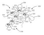
- a bone plate for the coronoidhas a plurality of ring elements including a central ring element, each of the ring elements having a threaded hole for receiving a locking fastener.
- the bone platealso has a plurality of bendable bridge elements interconnecting the ring elements, and the plurality of ring elements are arranged into a plurality of arms extending radially from the central ring element.
- the plurality of armsmay include a first arm extending distally from the central ring element, a second arm extending medially from the central ring element and a third arm extending laterally from the central ring element.
- the first armmay have three of the plurality of ring elements spaced apart and arranged linearly, and the second arm may have one of the plurality of ring elements, and the third arm may have one of the plurality of ring elements.
- the bone platemay also have a buttress element attached to one of the plurality of ring elements by a bendable web element, and the bendable web element is reconfigurable in situ such that the buttress element can bear against the bone surface.
- the buttress elementmay extend proximally from the central ring element.
- the buttress elementalso may extend medially from the ring element of the second arm.
- the bone platemay also have a plurality of drill guides, and each of the ring elements is preassembled with one of the drill guides.
- the drill guidesmay be removably attachable to a bending tool, such that a user may use a pair of bending tools to apply a leveraging force to reconfigure, in situ, each of the first, second and third arms.
- a bone plate for the olecranonhas a body portion having a distal end, a proximal end, a longitudinal axis, a medial edge and a lateral edge.
- the bone platealso has a head portion transversely positioned on the distal end of the body portion.
- the bone platealso has a proximal arm extending proximally from the head portion and including a proximal ring element attached to the head portion by a proximal bendable bridge element, such that the proximal arm is reconfigurable in a sagittal plane containing the longitudinal axis and perpendicular to the top surface.
- the bone platealso has a plurality of threaded holes, and each threaded hole defines a thread axis and can receive a fixed-angle locking fastener for attaching the bone plate to the bone.
- the proximal ring elementmay have at least one threaded hole, and the body portion may have a plurality of threaded holes aligned longitudinally, and the head portion may have two threaded holes aligned transversely.
- the two thread axes of the head portionare transversely offset from the thread axis of the proximal ring element, such that when the proximal arm is reconfigured in the sagittal plane in a direction to result in the thread axis of the proximal ring element to converge with the two thread axes of the head portion, the thread axis of the proximal ring element passes between the two thread axes of the head portion.
- the bone platemay also have a medial arm extending medially from the body portion and including a medial ring element attached to the medial edge of the body portion by a medial bendable bridge element.
- the bone platemay also have a lateral arm extending laterally from the body portion (opposite of the medial arm, where provided) and including a lateral ring element attached to the lateral edge of the body portion by a lateral bendable bridge element, and each of the medial and lateral ring elements may have a threaded hole defining a thread axis for receiving a fixed-angle locking fastener.
- the medial and lateral bridge elementsare configured such that the axes through the holes of the medial and lateral ring elements generally converge toward each other, but do not extend within a common plane.
- the bone platemay also have a plurality of drill guides, wherein each of the threaded holes is preassembled with one of the drill guides.
- the drill guidesmay be removably attachable to a bending tool, such that a user may use a pair of bending tools to apply a leveraging force to reconfigure, in situ, each of the medial, lateral and proximal arms.
- the bone platemay also have a slot in the body portion for receiving a non-locking compression fastener.
- a bone platehas a tapered, threaded hole configured for receiving a fixed-angle, locking fastener having a tapered, threaded head to engage the tapered, threaded hole for attaching the bone plate to the bone, the threaded hole defining a hole axis.
- the systemalso has a multidirectional compression fastener for insertion into the tapered, threaded hole for attaching the bone plate to the bone.
- the multidirectional compression fastenerhas an elongated shank portion having proximal and distal ends and defining a fastener axis.
- the multidirectional compression fasteneralso has a smooth, frustoconically shaped head with a large diameter end and a small diameter end, and the small diameter end is attached to the proximal end of the shank portion, and the large diameter end has a circular, peripheral edge that defines a proximal face with a recess for receiving a driving tool.
- the multidirectional compression fasteneris fully insertable into the tapered, threaded hole, such that the smooth, frustoconically shaped head compresses against the tapered, threaded hole, and the fastener axis and the hole axis define an insertion angle.
- the elongated shankmay be at least partially threaded for engagement into the bone.
- the insertion anglemay range from zero to about 15 degrees and may be contained in any plane containing the hole axis.
- the circular, peripheral edgemay also have an external radius.
- the smooth, frustoconically shaped headmay define an included angle of about 42 degrees centered on the fastener axis.
- the systemmay also have a slot extending through the thickness of the bone plate, and the slot is sized and configured to receive a conventional compression screw having a spherical head.
- the systemmay also have a washer for receiving the multidirectional compression fastener.
- the washerhas a bore therethrough for receiving the multidirectional compression fastener and an outer surface sized and shaped similarly to the spherical head of the conventional compression screw, such that the multidirectional compression fastener and the washer may be used in combination in the slot in a similar manner as a conventional compression screw to aid in the reduction of the bone fracture and to attach the bone plate to the bone.
- a portion of the bore of the washermay be conically shaped, such that the proximal face of the multidirectional compression faster is approximately flush with the top of the washer when fully inserted into the washer.
- the screw and washerare engageable together such that they may be handled together as a unit during a surgical procedure.
- the systemhas a bone plate having a threaded hole defining a thread axis for receiving a fixed angle, locking fastener.
- the systemalso has a drill guide preassembled into the threaded hole, the drill guide including a drill guide bore sized to guide a bone drill.
- the systemalso has an insertion tool having a cylindrical body with distal and proximal ends and a longitudinal axis extending therebetween. The cylindrical body has a grip surface for holding the insertion tool during use.
- the cylindrical bodyalso has a longitudinal bore extending between the distal and proximal ends and sized for guiding a K-wire, and the distal end is configured to be removably attached to the drill guide so that the longitudinal bore aligns with the thread axis.
- the distal end of the insertion toolmay also fit securely into the drill guide, such that the user may use the cylindrical body as a handle to manipulate the bone plate during the surgical procedure.
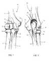
- FIG. 1is an anterior (front) view of the bones of the human elbow joint
- FIG. 2is a posterior (back) view of the bones of the human elbow joint
- FIG. 3is a top perspective view of a proximal radius plate
- FIG. 3Ais a top perspective of a smaller version of a proximal radius plate
- FIG. 4is a bottom perspective view of the proximal radius plate of FIG. 3 ;
- FIG. 5is a perspective view of a pair of bending tools as they may be applied in situ to reconfigure the proximal radius plate of FIG. 3 ;
- FIG. 6is perspective view of the bending tools of FIG. 5 as they may be alternately applied in situ to reconfigure the proximal radius plate of FIG. 3 ;
- FIG. 7is a bottom perspective view of the proximal radius plate of FIG. 3 with a plurality of fasteners fully inserted;
- FIG. 8is a wire frame, lateral view of the proximal radius plate of FIG. 3 attached with a plurality of fasteners to the proximal radius;
- FIG. 9is a top, medial perspective view of a lateral plate for the distal humerus
- FIG. 10is a top, lateral perspective view of the lateral plate of FIG. 9 ;
- FIG. 11is a bottom perspective view of the lateral plate of FIG. 9 ;
- FIG. 12is a top perspective view of a medial plate for the distal humerus
- FIG. 13is a bottom perspective view of the medial plate of FIG. 12 ;
- FIG. 14is an anterior, transparent view of the distal humerus with the lateral and medial plates of FIGS. 11 and 12 attached thereto by a plurality of fasteners;
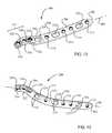
- FIG. 15Ais a top perspective view of a posterolateral plate for the distal humerus
- FIG. 15Bis a bottom perspective view of the posterolateral plate of FIG. 15A ;
- FIG. 16is top perspective view of the posterolateral plate of FIG. 15A , shown preassembled with a plurality of first drill guides;
- FIG. 17is top perspective view of the posterolateral plate of FIG. 15A , shown with a plurality of fasteners fully inserted;
- FIG. 18is a wire frame drawing of the posterolateral plate of FIG. 15A attached to the posterolateral surface of the distal humerus;
- FIG. 18Ais posterior, transparent view of the distal humerus with the medial and posterolateral plates of FIGS. 12 and 15A attached thereto by a plurality of fasteners;
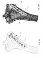
- FIG. 19is a top perspective view of a coronoid plate
- FIG. 20is a bottom perspective view of the coronoid plate of FIG. 19 ;
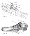
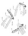
- FIG. 21is wire frame view of the coronoid plate of FIG. 19 attached to coronoid of the proximal ulna;
- FIG. 22is a transparent view of the coronoid plate of FIG. 19 attached to the coronoid of the proximal ulna;
- FIG. 23Ais a top perspective view of an olecranon plate
- FIG. 23Bis a bottom perspective view of the olecranon plate of FIG. 23A ;
- FIG. 23Cis a bottom perspective view of the olecranon plate of FIG. 23A , including a plurality of fasteners fully inserted;
- FIG. 24is top perspective view of the olecranon plate of FIG. 23A preassembled with a plurality of first drill guides of FIG. 41 ;
- FIG. 25is a transparent side view of the olecranon plate of FIG. 23A attached to the olecranon of the proximal ulna;
- FIG. 26is a top perspective view of another embodiment of an olecranon plate
- FIG. 27is a head end view of a conventional compression screw
- FIG. 28is a side view of the compression screw of FIG. 27 ;
- FIG. 29is a head end view of a multidirectional locking screw
- FIG. 30is a side view of the multidirectional locking screw of FIG. 29 ;
- FIG. 31is a cross-sectional view of the multidirectional locking screw of FIG. 29 inserted into a threaded hole of a bone plate;
- FIG. 32is a perspective view of a fixed-angle locking screw
- FIG. 33is a head end view of the fixed-angle locking screw of FIG. 32 ;
- FIG. 34is a detailed cross-sectional view of the proximal portion of the fixed-angle locking screw of FIG. 32 ;
- FIG. 35is a perspective view of a multidirectional compression screw
- FIG. 36is a detailed, cross-sectional view of the multidirectional compression screw of FIG. 35 ;
- FIG. 37is a detailed, cross-sectional view of the multidirectional compression screw of FIG. 35 inserted into a bone plate at an insertion angle C;
- FIG. 38is a detailed, cross-sectional view of the multidirectional compression screw of FIG. 35 inserted into a bone plate at an insertion angle of zero;
- FIG. 39is a perspective view of a washer for use with the multidirectional compression screw of FIG. 35 ;
- FIG. 40is a cross-sectional view of the washer and multidirectional compression screw of FIG. 39 assembled into a slot of a bone plate at an insertion angle F;
- FIG. 41is a perspective view of a first drill guide that may be preassembled into a tapered, threaded hole of a bone plate;
- FIG. 42is another perspective view of the first drill guide shown in FIG. 41 ;
- FIG. 43is a perspective view of a second drill guide that may be preassembled into a tapered, threaded hole of a bone plate;
- FIG. 44is another perspective view of the second drill guide shown in FIG. 43 ;
- FIG. 45is a perspective view of the first drill guide of FIG. 41 and the second drill guide of FIG. 43 preassembled into the distal portion of a bone plate shown;
- FIG. 46is a perspective view of a distal portion of a first embodiment of a bending tool
- FIG. 47is a perspective view of a first embodiment of a pair of the bending tools shown in FIG. 46 as they may be used to reconfigure the bone plate shown in FIG. 48 in an x-y plane;
- FIG. 48is a perspective view of the pair of bending tools shown in FIG. 47 as they may be used to reconfigure the bone plate in a y-z plane;
- FIG. 49is a perspective view of a first bending tool of a second embodiment of a pair of bending tools
- FIG. 50is a perspective view of a second bending tool of the second embodiment of a pair of bending tools
- FIGS. 51A-Care perspective views of the pair of bending tools shown in FIGS. 49 and 50 as they may be used to reconfigure the bone plate in a y-z plane;
- FIG. 52is a side elevation view of a K-wire insertion tool
- FIG. 53is a perspective view of the K-wire insertion tool shown in FIG. 52 ;
- FIG. 54is a cross-sectional view of the distal portion of the guide wire insertion tool of FIG. 52 removably attached to the first drill guide shown in FIG. 41 .
- FIG. 1is an anterior (front) view and FIG. 2 is a posterior (back) view of the bones of the human elbow joint 10 : the distal humerus 12 , the proximal radius 14 and the proximal ulna 16 .
- the distal humerus 12includes the coronoid fossa 18 , the capitellum 20 , the trochlea 22 , the medial epicondyle 24 and the lateral epicondyle 26 , and the olecranon fossa 28 therebetween.
- the proximal radius 14includes the radial head 30 .
- the proximal ulna 16includes the coronoid process 32 ( FIG. 1 ) and the olecranon 34 ( FIG.
- distal humerus 12which articulates within the olecranon fossa 28 between the lateral and medial epicondyles 24 , 26 of distal humerus 12 .
- Each of the distal humerus 12 , proximal radius 14 and proximal ulna 16are susceptible to a large variety of fractures, such as during a fall.
- the present system for the repair of elbow fracturesmay include a plurality of anatomically specific bone plates and a plurality of fasteners for the attachment of the plates to the bone.
- the systemmay include a proximal radius plate for repair of the proximal radius.
- the systemmay also include a lateral plate, a medial plate and a posterolateral plate for repair of the distal humerus.
- the systemmay further include an olecranon plate and a coronoid plate for the repair of the proximal ulna.
- each of the bone plates of the system described hereinare designed to fit closely to specific bone surfaces of the elbow joint, the plates share numerous advantages compared to conventional plates.
- each of the plateshas portions that are reconfigurable in situ, such that the surgeon may alter the bone plate shape while it is positioned on the bone to more closely fit and support the bone surface. This also allows the surgeon to redirect the trajectories of the fasteners if necessary to capture bone fragments or to avoid intersecting other fastener trajectories.
- each of the plates described hereinmay be preassembled with a plurality of drill guides, such as either of a first drill guide 1400 shown in FIG. 41 , a second drill guide 1500 shown in FIG. 43 , or a combination thereof.
- Each of the plates of the present systemmay be formed from any one of numerous materials known in the art, including a stainless steel, a titanium and a titanium alloy such as Ti-6Al-4V.
- Each of the platesis preferably machined from a solid round bar of Ti-6Al-4V-ELI in the fully annealed condition.
- Each plateis machined to its respective anatomical shape, described below, to ensure minimal work hardening. After machining, the parts are polished and anodized. The resulting plate material is fully ‘soft’ and enable in situ shaping without fracture of the plate, as described in detail below.
- each of the plates described hereinare significantly thinner than currently available plates for the same types of fractures, yet still has the appropriate stiffness to support the respective fractured bone.
- each of the fasteners provided to attach the bone plates to the bone described hereinhas a low profile design, i.e., the head of each fastener is configured to seat relatively flush to the top surface of the plate, thereby minimizing trauma to surrounding soft tissues.
- Each of the bone plates of the present systeminclude a plurality of holes, wherein each hole may be configured to receive any one of the bone fastener embodiments shown in FIGS. 28 through 40 , including a standard compression screw 700 shown in FIG. 28 , a fixed-angle locking screw 1100 shown in FIG. 32 , a multidirectional locking screw 1000 shown in FIG. 30 , a multidirectional compression screw 1200 shown in FIG. 35 , and a multidirectional compression screw 1200 with washer 1300 shown in FIG. 40 .
- Each of the plates of the present systemincludes at least one hole for receiving a locking fastener, such as either of fixed-angle locking screw 1100 and multidirectional locking screw 1000 .
- FIG. 3is a perspective view of a top surface 101 and FIG. 4 is a perspective view of a bottom surface 103 of a bone plate 100 for the proximal radius, also called radial plate 100 .
- Radial plate 100has a rigid body 102 with a proximal end 104 , a distal end 106 , a top surface 101 , a bottom surface 103 defining longitudinal axis 108 having a convex proximal portion.
- Rigid body 102has a medial edge 110 and a lateral edge 112 .
- Radial plate 100may be symmetrically shaped as shown in FIG. 3 , such that it may be used on either of the right and left elbows, as described in more detail below.
- Rigid body 102also includes a first central hole 176 and a second central hole 186 , each extending between the top surface 101 and the bottom surface 103 , for receiving a bone fastener for attaching radial plate 100 to the bone.
- a first arm 120extends proximal-medially from rigid body 102 and includes a first ring element 122 and a first bendable bridge element 124 attached to medial edge 110 of rigid body 102 .
- Ring element 122has a first hole 126 for receiving a bone fastener.
- First bendable bridge element 124is curved so that first arm 120 extends initially from rigid body 102 in the medial direction, and then finally in the proximal direction.
- the amount of curvature shown in FIGS. 3 and 4 of first arm 120is approximately 90 degrees and not within a single plane, although the curvature may vary.
- the width across the first arm at B 1is less than the width across the first arm at B 2 .
- radial plate 100may also include a second arm 130 extending proximal-laterally.
- Second arm 130includes a second ring element 132 attached to lateral edge 112 of rigid body 102 by a second bendable bridge element 134 , which is also curved and opposing first bendable bridge element 124 .
- second arm 130may be, but is not necessarily, a mirror image of first arm 120 .
- the width across the second arm at B 3is less than the width across the second arm at B 4 .
- Second ring element 132includes a second hole 136 for receiving a bone fastener.
- Radial plate 100may also include a third arm 140 extending proximally from rigid body 102 and between first arm 120 and second arm 130 .
- Third arm 140includes a third ring element 142 attached to proximal end 104 of rigid body 102 by a third bridge element 144 having a third hole 146 for receiving a bone fastener.
- Each of the first, second and third arms 120 , 130 , 140is less stiff than the rigid body 110 , but together have a combined stiffness that approximates (within 20%, and more preferably ⁇ 10%) the stiffness of the rigid body.
- First, second and third arms 120 , 130 and 140are spaced apart to form an out-of-plane fork-like (preferably trident) shape, thereby allowing visualization of the bone surface there beneath.
- the first, second and third rings 122 , 132 , and 142are preferably relatively situated so as to be positioned approximately about the exterior of an imaginary sphere. This adapts the rings 122 , 132 , 142 for seating on the metaphyseal surface of the proximal radius, which is generally cylindrically curved in the medial-lateral direction and convex in the longitudinal direction, at least at the proximal end in a manner which approximates a spherical shape.
- the axes 127 , 137 and 147 of the holes 126 , 136 and 146criss-cross through a common central axis 190 which aligns with the predicted center of the articular surface 192 of the proximal radius 30 for which the proximal radius plate 100 is sized.
- the central axis 190 along which the holes axes 127 , 137 , 147 criss-crosswill be further from the plate, and when the plate is design for use on smaller radius bones, the central axis 190 along which the hole axes 127 , 137 , 147 criss-cross will be closer to the plate.
- FIG. 3Aillustrates a radial plate 100 a scaled down in size relative to radial plate 100 to accommodate smaller radius bones.
- the bridge elements 124 a , 134 a , and 144 aare differently oriented relative to bridge elements 124 , 134 , 144 so as to configure the rings 122 a , 132 a , 142 a to define a smaller radius of curvature therebetween so that the rings are adapted to seat on a smaller proximal radial head.
- the axes through the holes in the ringscriss-cross closer to the plate.
- each of the first, second and third arms 120 , 130 and 140may be individually reconfigured, as necessary, by the surgeon to fit the bone surface and to change the trajectories of fasteners inserted through the rings of such arms.
- Radial plate 100may also include a fourth arm 150 extending distally from rigid body 102 along longitudinal axis 108 .
- Fourth arm 150includes a fourth ring element 152 having a fourth hole 156 and connected to distal end 106 of rigid body 102 by a fourth bendable bridge element 154 .
- Radial plate 100may also include a fifth arm 160 extending distally from fourth ring element 152 .
- Fifth arm 160includes a fifth ring element 162 having a fifth hole 166 and attached to fourth ring element 152 by a fifth bendable bridge 164 .
- Each of first, second, third, fourth, fifth, first central and second central holes 126 , 136 , 146 , 156 , 166 , 176 and 186 , respectively,is preferably taper threaded to receive any one of multidirectional locking screw 1000 , fixed-angle locking screw 1100 , and multidirectional compression screw 1200 .
- a plurality of drill guidesmay be preassembled to radial plate 100 to facilitate drilling fastener holes into the bone and to provide instrumentation attachment points for reconfiguring radial plate 100 during the surgical procedure.
- Each of first, second, third, fourth, fifth, first central and second central holes 126 , 136 , 146 , 156 , 166 , 176 and 186 , respectively,may be configured, such as with a tapered thread, to receive a first, second, third, fourth, fifth, first central and second central drill guide, 128 , 138 , 148 , 158 , 168 , 178 and 188 , respectively, each of which is preferably first drill guide 1400 ( FIG. 41 ).
- FIG. 5is a perspective view of a pair of bending tools 2160 , 2180 as they may be applied in situ to reconfigure fourth arm 150 of radial plate 100 .
- FIG. 6is a perspective view of bending tools 2160 , 2180 as they may be applied in situ to reconfigure first arm 120 of radial plate 100 .
- Bending tool 2160is formed into an L-shape from a metal rod, wherein one longer portion of the L-shape comprises a handle 2166 and the other shorter portion comprises an arm 2168 .
- a first end effector 2162is attached to the free end of handle 2166 and a second end effector 2164 is attached to the free end of arm 2168 .
- Each of first and second end effectors 2162 , 2164may be securely yet removably attached to any one of drill guides 128 , 138 , 148 , 158 , 168 , 178 and 188 ( FIG. 3 ), as shown in FIGS. 5 and 6 .
- Bending tool 2180is also formed into an L-shape from a metal rod, wherein one longer portion of the L-shape comprises a handle 2186 and the other shorter portion comprises an arm 2188 .
- a first end effector 2182is attached to the free end of handle 2186 and a second end effector 2184 is attached to the free end of arm 2188 .
- Each of first and second end effectors of either of tools 2860 , 2180may be securely yet removably attached to any one of drill guides 128 , 138 , 148 , 158 , 168 , 178 and 188 ( FIG. 3 ), as shown in FIGS. 5 and 6 .
- FIGS. 5 and 6An x-y-z coordinate system is shown in each of FIGS. 5 and 6 .
- the x-y planeapproximately corresponds to the medial-lateral direction and the x-z direction approximately corresponds to the anterior-posterior direction with respect to the surface of the proximal radius.
- FIG. 5shows how bending tools 2160 , 2180 may be attached to bend bridges 154 , 164 in the x-z plane by applying the leveraging force in the direction of arrows 2192 , or to be also used to twist bridges 154 , 164 about the x-axis by applying the leveraging force in the direction of the arrows 2190 .
- equal but oppositely directed forcesmay be applied to each of the bending tools 2160 , 2180 to generate the leveraging force or couple.
- radial plate 100may be reconfigured in situ to closely match the shape of the proximal radius surface. This also allows the surgeon to redirect the axes of holes 156 , 166 into a desired direction, such as to capture a bone fragment or to avoid a fracture line or fastener already inserted into the bone.
- FIG. 6shows how bending tools 2160 , 2180 may be used to twist first arm 120 in the y-z plane by applying the leveraging force in the direction of the arrows 2194 , or to twist first arm 120 in the x-z plane by applying the leveraging force in the direction of the arrows 2196 , such that ring element 122 fits closely against the proximal radius surface.
- first arm 120has a curvature of about 90 degrees and because the arm is narrower at B 1 than at B 2 , the arm 120 is structurally adapted to sweep in a predictable manner (the twisting of arm will be at or adjacent B 1 ) so as to minimize interaction between axis 137 and the other axes.
- second arm 130may also be reconfigured.
- Radial plate 100is provided to the user with a configuration that closely matches the majority of patients and with fastener trajectories (thread axes) that do not intersect.
- using bending tools 2160 and 2180allows fine, in situ adjustments to improve the quality of the internal fixation. The surgeon may quickly and safely make a reasonable number of small adjustments to the plate configuration without the danger of microcrack formation that may lead to fracture after implantation.
- a bendable plate (albeit of different configuration, structure and function), and the in situ use thereof, and a pair of dedicated bending tools for in situ bending of the plateare disclosed in co-owned U.S. Pub. No. 20060161158A1, 20070233111A1, and 20070233112A1, all of which are hereby incorporated by reference herein in their entireties.
- first or second ring elements 122 , 132 of the first and second arms 120 , 130will generally be slightly spaced from the surface of the bone.
- the spaced apart ringwill be the ring located at the lateral side of the radius bone.
- This configuration of the radial plate 100allows a single ‘ambidextrous’ radius plate to be used on either left or right radius bones in closest possible conformation to each such bone.
- the spaced apart ringmay be repositioned, if desired, to seat closer to the bone by the use of the bending tools.
- FIG. 7is a perspective view of bottom surface 103 of radial plate 100 with a plurality of fasteners fully inserted, including fasteners 129 , 139 , 149 , 159 , 169 , 179 and 189 into holes 126 , 136 , 146 , 156 , 166 , 176 and 186 , respectively.
- FIG. 8shows the radial plate 100 attached to the proximal radius.
- a plurality of fasteners 129 , 139 , 149 and 179form an interdigitating, rigid scaffold beneath the articular surface of the radial head.
- Holes 126 , 136 , 146 and 176correspond to thread axes 127 , 137 , 147 and 177 , respectively, which may be provided in an interdigitating arrangement, such that thread axis 127 passes between axes 137 and 177 , and thread axis 137 passes between axes 147 and 127 .
- axes 127 , 137 , 147 and 177are all distally directed relative to the bottom surface 103 of the radius plate 100 , with axis 147 being distalmost, axis 177 being proximalmost and extending toward a common point with axis 147 , and axes 127 and 137 extending transverse to each other (76° ⁇ 6° relative to each other in the medial-lateral direction) and between axes 147 and 177 . Due to the curved non-planar shape of first arm 120 , when the leveraging force is applied in the direction indicated by arrows 194 in FIG.
- first arm 120is biased to bend in the y-z plane, such that axis 127 may be redirected yet remain between axis 137 and 177 , and the corresponding fastener trajectories do not intersect.
- Second arm 130is biased to bend in a similar manner, such that axis 137 will not intersect either of axes 147 and 127 .
- This interdigitating arrangementprovides a strong, load-sharing scaffold while facilitating rapid attachment of radial plate 100 to the bone since hole re-drilling is minimized. If any of the arms 120 , 130 , 140 are twisted or bent by the surgeon, it is important that the axes 127 , 137 , 147 , and 177 continue to interdigitate, and not conflict.
- fasteners 129 , 139 , 149 and 179may span the proximal radius, such that the fastener tips anchor into cortical bone on the side of the bone opposite radial plate 100 .
- a common fracture locationis at the neck of the proximal radius head.
- Fastener 179is specifically intended to travel across the neck and span the fracture.
- This arrangementtogether with the use of locking fasteners, provide an exceptionally robust scaffold for supporting the articular surface of the proximal radius.
- fasteners 159 , 169 and 189extend diametrically across the diaphysis of the radius bone. These fasteners carry the load on the plate back to the diaphysis.
- Fourth arm 150 and fifth arm 160optionally can be removed, by reverse bending, if not required to support the fracture.
- FIGS. 9 , 10 and 11show a bone plate for the lateral surface of the distal humerus.
- FIG. 9is a perspective view of a top surface 208 and an anterior edge 248 of a lateral plate 200 for the distal humerus.
- FIG. 10is a perspective view of the top surface 208 and a posterior edge 250 of lateral plate 200 .
- FIG. 11is a perspective view of a bottom surface 210 of lateral plate 200 .
- Lateral plate 200includes a body 206 having a distal end 204 , a proximal end 202 and a curvilinear axis 209 .
- the bottom surface 210 at the distal end 204is concave along the longitudinal axis 209 , while the remainder of the bottom surface is flat or convex long the axis. This permits the distal end 204 to seat close to the lateral epicondyle 26 .
- a first locating foot 242 and a second locating foot 244extend downwardly (toward the bone surface) from posterior edge 250 and are provided to assist the surgeon during placement of lateral plate 200 onto the bone surface by seating on the bone contours of the posterior surface of the distal humerus.
- Each locating foot 242 , 244has a size (bone contacting surface area) preferably approximating the cross-sectional area of a screw hole ( 220 , 222 , 224 , 226 , 228 , 230 , 232 , discussed below).
- Lateral plate 200may also include a first segment 212 extending along curvilinear axis 209 from distal end 204 of body 206 .
- First segment 212is attached to distal end 204 by a first bendable bridge element 216 , which is offset from curvilinear axis 209 such that it forms a continuation of the posterior edge 250 .
- Lateral plate 200may further include a second segment 214 extending along curvilinear axis 209 and attached to first segment 212 by a second bendable bridge element 218 , which also is offset from curvilinear axis 209 and forms a continuation of the posterior edge 250 .
- First and second bendable bridge elements 216 , 218form a bendable spine 231 that is reconfigurable during the surgical procedure, as will be described.
- the bendable bridge elements 216 , 218are defined along the posterior edge 250 , rather than centrally located, so that when the patient's elbow is placed on a surface, the area of the plate which loads against the surface is smooth so as to prevent discomfort to the patient.
- the distal end 204 of body 206 , segment 212 , and segment 214each have squared off ends opposite the bendable spine 231 . This facilitates use of bending tools 1600 A, 1600 B, as described below with respect to FIGS. 46-48C .
- body 206includes first, second, third, fourth, and fifth holes 220 , 222 , 224 , 226 and 228 , respectively, each for receiving a fastener.
- Each of first and second segments, 212 and 214also include a hole 230 and 232 , respectively, for receiving a fastener.
- Holes 220 , 222 , 224 , 226 , 228 , 230 and 232preferably have a tapered thread for receiving any one of multidirectional locking screw 1000 , fixed-angle locking screw 1100 , and multidirectional compression screw 1200 , and also for receiving either one of first drill guide 1400 ( FIG. 41 ) or second drill guide 1500 ( FIG. 43 ).
- preassembled drill guides in segments 212 and 214allows the surgeon to use bending tools to reconfigure bendable spine 231 , as will be described for FIGS. 47 and 48 .
- the use of preassembled drill guides in holes 220 , 222 , 224 , 226 , 228permits additional reconfiguration of the plate.
- the use of preassembled drill guides in any of the threaded holesaids in drilling through the bone in alignment with the holes in the plate, as well as temporary fixation of the plate to the bone with K-wires, as described below.
- Lateral plate 200may also include two elongated slots 234 , 236 located in body portion 206 for receiving a compression screw such as either of standard compression screw 700 ( FIG. 27 ) or multidirectional compression screw 1200 ( FIG. 40 ).
- a compression screwsuch as either of standard compression screw 700 ( FIG. 27 ) or multidirectional compression screw 1200 ( FIG. 40 ).
- the compression fastenermay be inserted into slots 234 , 236 to dynamically compress lateral plate 200 in the vertical and axial directions to facilitate fracture reduction prior to insertion of the remaining fasteners.
- Lateral plate 200may also include cut-outs 246 a , 246 b on each side of elongated slot 234 and cut-outs 247 a , 247 b on each side of elongated slot 236 in order to (i) provide clearance at the edges of the plate for fasteners that are angled toward the posterior of the bone in order to attain maximum purchase on the bone, (ii) to normalize the stiffness on both sides of the slot, (iii) to reduce the stiffness of the plate at a slot to permit bending through a slot via the use of drill guides inserted into threaded holes on either side of a slot and appropriate bending tools, and/or (iv) to make that portion of body 206 less stiff than the adjoining portions, thereby allowing slight reconfiguration of body portion 206 to more closely match the shape of the bone surface upon insertion of a compression fastener.
- Increased clearanceis preferred at the posterior edge 248 of the plate adjacent slots 234 , 236 , as this is the side toward which the fasteners are angled for bone purchase. It is further preferred that the elongated slots 234 , 236 be centered off-axis from longitudinal axis 209 , but oriented parallel thereto so as to define two rails of different width connecting the portions of the plate on either side of the slot 234 . With respect to slot 234 (slot 236 is similarly structured), larger cut-out 246 a is provided in association with larger rail 249 a , and smaller cut-out 246 b is provided in association with smaller rail 249 b . This configuration provides additional clearance at the posterior edge for screw orientation into cortical bone.
- the area of the cut-outs 246 a , 246 bare preferably dimensioned such that each of the rails 249 a , 249 b has substantially equal stiffness (preferably within ten percent of each other, and more preferably within five percent of each other). However, the overall stiffness of the plate body in the region of the slot is reduced by the cut-outs to facilitate reconfiguration of the plate.
- Lateral plate 200may also include an hourglass-shaped openings 238 , 239 near distal end 204 .
- Opening 238reduces the stiffness of the plate between holes 224 , 226 to allow distal end 204 to be reconfigurable using bending tools such as shown in FIG. 5 without a discontinuation of posterior and anterior edges 248 , 250 .
- the opposing ends of opening 238may also be configured to guide a conventional K-wire to capture and hold bone fragments while adjacent fasteners are inserted.
- Opening 239functions between holes 226 and 228 in the same manner as opening 238 .
- each of the spacings 213 , 215 between segments 212 and 214 and between segment 212 and distal end 204 , respectively,may also be configured to guide a conventional K-wire.
- spacings 213 , 215may be shaped to retain a guidewire between a narrower central portion 213 a , 215 a and a larger closed end 213 b , 215 b (throat) ( FIG. 9 ).
- Lateral plate 200(as well as medial plate 300 or posterolateral plate 400 ) may optionally include one or more multifunctional hole that may be used to guide a conventional K-wire and as an attachment point for a suture. Such a multifunctional hole is described in detail in U.S. Pub. No. 20070270849A1, which is hereby incorporated by reference herein in its entirety.
- the lateral plateis, overall, progressively stiffer from the distal end to the proximal end, corresponding to the loads experienced at respective portions of the plate.
- the lateral plateis most preferably approximately 2 mm thick along its length and used in conjunction with a medial plate 300 , described below, of substantially the same thickness.
- lateral plate 200While it is not necessary to include all of the above described features in the lateral plate 200 , all such features can be included in an embodiment, and the inclusion of the described features is considered optimum for configuring the plate to the lateral surface of the distal humerus and for supporting fractures thereat.
- FIG. 12is a perspective view of a top surface 398 of a bone plate 300 for the medial surface of the distal humerus, also called a medial plate 300 .
- FIG. 13is a perspective view of a bottom surface 310 medial plate 300 .
- Medial plate 300is similar to lateral plate 200 , with variations in shape, size, and hole configuration.
- Medial plate 300includes a body 306 having a proximal end 302 , a distal end 304 and a curvilinear axis 309 .
- the bottom surface 310 at the distal end 304is concave along the curvilinear axis 309 , while the remainder of the bottom surface is slightly convex or flat along the axis. This permits the distal end 304 to seat close to the medial epicondyle 24 .
- Medial plate 300also includes a first segment 336 extending along curvilinear axis 309 from distal end 304 of body 306 .
- First segment 336is attached to distal end 304 by a first bendable bridge element 340 , which is offset from curvilinear axis 309 , such that it forms a continuation of a posterior edge 350 .
- Medial plate 300may further include a second segment 338 extending along curvilinear axis 309 and attached to first segment 336 by a second bendable bridge element 342 , which also is offset from curvilinear axis 309 and forms a continuation of the posterior edge 350 .
- First and second bridge elements 340 , 350preferably have a portion of reduced thickness (transverse to the axis 309 and width of the plate, and seen in FIG. 13 ), that facilitates bending thereof.
- First and second bendable bridge elements 340 , 342form a bendable spine 331 that is reconfigurable during the surgical procedure, as will be described for FIGS. 47 and 48 .
- the distal end 304 of the body 306 , segment 336 and segment 338each have squared off ends opposite the bendable spine 331 . This facilitates use of bending tools 1600 A, 1600 B, as described below with respect to FIGS. 46-48C .
- the bendable bridge elements 340 , 342are defined along the posterior edge 350 , rather than centrally located, so that when the patient's elbow is placed on a surface, the area of the plate which loads against the surface is smooth so as to prevent discomfort to the patient.
- body 306includes first, second, third, fourth and fifth holes, 312 , 314 , 316 , 318 and 320 , respectively, each for receiving a fastener.
- Each of the first and second segments 336 and 338also include a hole 322 and 324 , respectively, for receiving a fastener.
- Holes 312 , 314 , 316 , 318 , 320 , 336 and 338are preferably configured with a tapered thread to receive any one of multidirectional locking screw 1000 , fixed-angle locking screw 1100 or multidirectional compression screw 1200 , and either one of first drill guide 1400 and second drill guide 1500 .
- the use of preassembled drill guides in segments 322 and 324allows the surgeon to use bending tools such as shown in FIGS. 46 and 47 to reconfigure bendable spine 331 .
- Medial plate 300may also include a first elongated slot 326 , a second elongated slot 328 , and a third elongate slot 329 , each located in body portion 306 for receiving either one of standard compression screw 700 ( FIG. 27 ) and multidirectional compression screw 1200 ( FIG. 40 ) to facilitate the dynamic compression of medial plate 300 to the bone prior to insertion of the remaining fasteners.
- Medial plate 300may also include a cut-out 333 on each side of each of elongated slots 326 , 328 and 329 in order to make that portion of body 306 less stiff than the adjoining portions, thereby allowing slight reconfiguration of body portion 306 to more closely match the shape of the bone surface.
- drill guides assembled in threaded holes 312 , 314 , 316 , 318 , 320 on opposite sides of slots 326 , 328 , 329may be subject to force with tools to reconfigure the plate about the slot, and
- standard compression screw 700may be inserted into each of slots 326 and 328 and tightened in order to draw bottom surface 310 against the bone, prior to insertion of the remaining fasteners.
- medial plateIt is an important feature of the medial plate that it is, overall, progressively stiffer from the distal end to the proximal end, corresponding to the loads experienced at respective portions of the plate.
- FIG. 14is a posterior, transparent view of the distal humerus, showing lateral plate 200 attached near the lateral epicondyle 26 and medial plate 300 attached near the medial epicondyle 24 by a plurality of fasteners.
- lateral plate 200 and medial plate 300may be attached to the distal humeral during the surgical procedure.
- the lateral and medial plates 200 , 300are located on the humeral bone in a “parallel” configuration, with the plates provided on opposite lateral and medial portions of the bone.
- the lateral and medial plates 200 , 300are preferably provided in different lengths so that the respective proximal ends 202 , 302 of the plates end at different locations on the bone and thereby reduce stress concentrations on the bone.
- a combination of cancellous (coarsely threaded) and cortical (finely threaded) fastenersmay be used.
- Lateral plate 200 and medial plate 300may be provided with fastener holes configured for receiving fixed-angle locking screw 1100 , such that the trajectories of the screws are unlikely to intersect.
- the surgeonmay also attach lateral plate 200 and medial plate 300 to the distal humerus using either of multidirectional locking screw 1000 and multidirectional compression screw 1200 .
- the surgeonmay insert the fasteners with a desired trajectory to avoid other fasteners and fracture lines and to capture bone fragments.
- FIG. 15Ais a top perspective view and FIG. 15B is a bottom perspective view of a posterolateral plate 400 for the distal humerus.
- Posterolateral plate 400includes a body 406 having a proximal end 402 , a distal end 404 and a curvilinear, longitudinal axis 403 extending therebetween.
- a first arm 410 and a second arm 420extend from distal end 404 on opposing sides of axis 403 , thereby forming a Y-shape.
- a third arm 430extends from the body 406 adjacent distal end transversely away from axis 403 . Alternatively, third 430 can extend from second arm 420 .
- First arm 410has a first arm axis 413
- second arm 420has a second arm axis 423
- third arm 430has a third arm axis 433 .
- Third arm axis 433is transverse to axis 403 , such that third arm 430 may wrap partially around the lateral side of the distal humerus.
- first arm 410includes a first ring element 412 having a hole 414 and is attached to proximal end 404 of body 406 by a first bendable bridge element 416 .
- Second arm 420includes a second ring element 422 having a hole 424 and attached to distal end 404 by a second bendable bridge element 426 .
- Third arm 430includes a third ring element 432 having a hole 434 and attached to body 406 by a third bendable bridge element 436 .
- Body 406includes holes 440 , 442 , 444 , 446 and 448 , and an elongated slot 450 , each of which may be located along longitudinal axis 403 .
- Each of holes 440 , 442 , 444 , 446 , 448 , 414 , 424 and 434may be configured with an internal taper thread for receiving any one of multidirectional locking screw 1000 , fixed-angle locking screw 1100 , or multidirectional compression screw 1200 shown in FIGS. 32 , 30 and 35 , respectively.
- Slot 450may be configured to receive either one of standard compression screw 700 and multidirectional compression screw 1200 shown in FIGS. 27 and 40 , respectively.
- Slot 450includes cutouts 452 on either side thereof to reduce the stiffness of the body 406 at the slot.
- Posterolateral plate 400also includes two hourglass-shaped openings 454 , 456 at the distal side of slot 450 .
- Each opening 454 , 456is substantially similar in design to hourglass shaped slot 238 of lateral plate 200 .
- Such opening 454 , 456reduce the stiffness of the plate between holes to allow the distal end 404 of the body 406 to be reconfigurable using bending tools such as shown in FIG. 5 without a discontinuation of the anterior and posterior edges of the plate as well as retain K-wires for temporary fixation.
- FIG. 16is top perspective view of posterolateral plate 400 , shown preassembled with a plurality of first drill guides 1400 ( FIG. 41 ) and second drill guides 1500 ( FIG. 43 ).
- bending tools 2160 , 2180may be used to reconfigure posterolateral plate 400 while the plate is positioned on the bone surface. In this way, the surgeon may closely match the shape of posterolateral plate 400 to the bone surface and redirect the trajectories of the fasteners to capture bone fragments and avoid fracture lines and other fasteners.
- Slot 450is longer than a conventional compression screw slot to reduce the axial torsional stiffness thereat.
- guides in holes 444 and 446may be used to impart a torque along the axis of the plate to result in an twist to enhance conformation of the plate to the bone, as well as impart a bending force across hourglass-shaped opening 454 . Additionally, guides in holes 446 and 448 can be used to impart a bending force across hourglass-shaped opening 456 .
- Third arm 430is coupled to the body portion 406 near hole 446 ; thus the plate 400 is highly adjustable in shape on either side of the location at which the third arm 430 is attached.
- Guides in holes 413 , 423 , 433in conjunction with appropriate bending tools, can be used to impart bending forces to reconfigure the orientation of the arms 410 , 420 , 430 to approximate the ring elements 412 , 422 , 432 to the bone and redirect the axes through the holes, if necessary.
- arm 430can be reconfigured to about the humerus to squeeze the lateral condyle 26 and provide lagging.
- FIG. 17is top perspective view of posterolateral plate 400 , shown with a plurality of fasteners 441 , 443 , 445 , 447 , 449 , 415 , 425 and 435 fully inserted and locked into holes 440 , 442 , 444 , 446 , 448 , 414 , 424 and 434 , respectively.
- Fastener 451is fully inserted into slot 450 .
- Each of fasteners 415 , 425 and 435 , 445has an axis 419 , 429 , 439 , and 461 , respectively, wherein axes 419 , 429 and 461 are approximately parallel, and axis 439 extends transverse to axes 419 , 429 and 461 and between axes 419 , 421 and axis 461 .
- each of first ring element 410 , second ring element 420 and third ring element 430have a bottom surface 411 , 421 and 431 , respectively, each of which is configured to conform to the bone surface, but is approximately planar.
- the thickness of first and second ring elements 412 , 422is greater at a distal region than at a relatively proximal region where the ring elements are coupled to the first and second bridge elements 416 , 426 . As shown in FIGS.
- each of axes 419 , 429 and 439is preferably non-perpendicular to bottom surfaces 411 , 421 and 431 , respectively, such that the trajectories of fasteners 419 , 429 and 439 , are optimized for capturing bone fragments and supporting the subchondral surface of the distal humerus.
- the load from fasteners 415 , 425 , 435 and 439is transferred along the plate and to fasteners 441 , 443 , and 445 , where the load is transferred back to the load bearing diaphysis of the humerus.
- FIG. 18is a wire frame drawing of the posterolateral plate 400 attached to the posterolateral surface of the distal humerus.
- FIG. 18Ais a transparent view showing the medial and posterolateral plates 300 , 400 together attached to the distal humerus in a “perpendicular” approach.
- the medial plateis provided at the medial side of the distal humerus bone while the posterolateral plate is provided at the posterolateral portion of the distal humeral bone.
- loading of the plateis in the direction of the height of the plate. Therefore, the posterolateral plate is substantially thicker than the medial plate.
- the posterolateral plateis preferably approximately 3.5 mm thick; i.e., 1.75 times the thicker than the medial plate). Fracture fixation using the perpendicular approach with the medial and posterior plates provides substantially the same stiffness as the parallel approach with the lateral and medial plates 200 , 300 .
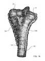
- FIG. 19is a perspective view of a top surface 501 of a bone plate 500 , also called a coronoid plate 500 , for the coronoid of the proximal ulna.
- the coronoid plate 500is specifically designed to seat on a ridge of the bone.
- FIG. 20is a perspective view of a bottom surface 503 of coronoid plate 500 .
- FIG. 21shows the coronoid plate 500 attached to the proximal ulna.
- Coronoid plate 500includes a central ring element 502 containing a hole 505 for receiving a fastener for attachment to the bone.
- Coronoid platealso includes a first arm 510 extending distally from central ring element 502 .
- first arm 510includes a first, a second and a third ring element, 512 , 514 and 516 , respectively, interconnected in series to central ring element 502 by a first, a second and a third bendable bridge element, 511 , 518 and 519 , respectively, and having a first, a second and a third hole, 513 , 515 and 517 , respectively.
- the lower surface of ring elements 512 , 514 , 516is concave in the medial-lateral direction. Referring to FIGS.
- This surface 38has a maximum of soft tissue in the area to cover the ends of any exiting fasteners.
- Coronoid plate 500may also include a second arm 520 extending medially from central ring element 502 .
- Second arm 520may include a fourth ring element 522 with a fourth hole 523 connected to central ring element 502 by a fourth bendable bridge element 521 .
- Second arm 520may also include a first buttress element 524 (preferably in the form of a tab or paddle) connected to fourth ring element 522 by a bendable web element 525 , thereby extending second arm 520 medially.
- the upper and lower surfaces of the first buttress element 524is oriented at an oblique angle (shown by corresponding axis D) relative to the central axis 528 through fourth hole 523 in the fourth ring element 522 .
- First buttress element 524provides cantilevered support without having to drill a hole, as the surgical approach does not afford suitable access to drill a hole and insert a fastener.
- Coronoid plate 500may also include a third arm 530 extending laterally from central ring element 502 .
- Third arm 530may include a fifth ring element 532 with a fifth hole 533 connected to central ring element 502 by a fifth bendable bridge element 531 .
- Coronoid plate 500may also include a second buttress element 526 connected to central ring element 502 by a second bendable web element 527 and extending proximally.
- Second buttress element 526provides support for the sublime tubercle which is too small a fragment for drilling.
- the relative shapes and sizes of buttress element 526 and web element 527also permit the structure to be used as an attachment location for suture, which can be wrapped around the web element 527 and sewn into a ligament.
- Each of holes 513 , 515 , 517 , 523 and 533is preferably configured with a tapered thread to receive any one of multidirectional locking screw 1000 , fixed-angle locking screw 1100 , and multidirectional compression screw 1200 .
- Holes 513 , 515 , 517 , 523 and 533also may be configured to be preassembled with either one of first drill guide 1400 and second drill guide 1500 .
- bending tools 2160 , 2180may be used to reconfigure coronoid plate 500 while the plate is positioned on the bone surface. In this way, the surgeon may closely match the shape of coronoid plate 500 to the bone surface and also redirect the trajectories of the fasteners to capture bone fragments and to avoid fracture lines and other fasteners.
- Bendable web elements 525 , 527may be reconfigured using conventional surgical pliers or the like to position buttress elements 524 and 526 against the bone surface, thereby providing additional support to the healing bone fragments.
- Each of bendable web elements 525 , 527 and bendable bridge elements 511 , 518 , 519 , 521 and 531may be easily broken by repeated reverse bending through a significantly large angular range using conventional surgical pliers or the like.
- the surgeonmay easily create the break, such that the broken edge of the implant is directed towards the bone surface in order to prevent injury to surrounding soft tissue. In this way, the surgeon may customize coronoid plate 500 according to the anatomy of the patient.
- arms 510 , 520 and 530 , and bottom surface 503 under each of ring elements 512 , 514 , 516 , 522 and 532may be shaped to closely match the contour of the bone at the coronoid of most patients, although other shapes are possible.
- FIG. 22is a perspective, transparent view of coronoid plate 500 attached to coronoid 16 of the proximal ulna.
- four ring elements 502 , 512 , 514 , 516 forming a backbone of the platesit on a ridge of the bone.
- This configurationpermits relative easy access to plate placement by the surgeon and also allows the plate to be kept away from ligament insertion points and to facilitate.
- a plurality of bicortical fastenersmay be used to create a stable construct for holding bone fragments in healing alignment and sharing the load transferred through the joint.
- the buttress elements 524 , 526provide the plate 500 with structure that permit fracture support even though there is not commonly ready access to that portion of the bone and where maintaining low profile support is a significant consideration.
- the preferred coronoid plate 500includes a central ring 502 coupled to one arm 532 having a single hole 533 , another arm 527 having a single buttress 526 and no hole, another arm having a single hole 523 and a single buttress 524 , and another arm having a plurality of holes 513 , 515 , 517 and no buttress.
- the coronoid plate 500functions as a buttress to counteract the tendency of the elbow to subluxate while also holding the small fragments in healing alignment.
- the above described configuration of the coronoid plate 500is preferred as it is considered to be optimum for support of the underlying bone fracture.
- FIGS. 23A through 25are views of a bone plate 600 for the olecranon of the proximal ulna.
- FIG. 23Ais a top perspective view and FIG. 23B is a bottom perspective view of the olecranon plate 600 , which includes a proximal end 604 , a distal end 602 and a longitudinal axis 612 extending therebetween.
- Olecranon plate 600includes a body portion 606 , a head portion 610 near proximal end 604 and a neck portion 608 connecting body and head portions, 606 and 610 .
- Neck portion 608is transversely narrower than either of body portion 606 and head portion 610 and increases in thickness toward the head portion.
- Head portion 608includes a head axis 614 that is transverse to longitudinal axis 612 of body portion 606 .
- Olecranon plate 600has a top surface 601 , a bottom surface 603 , a medial edge 605 and a lateral edge 607 .
- Body portion 606may include a plurality of holes 622 , 624 , 626 , 628 for receiving bone fasteners. Body portion 606 may also include at least one slot 634 for receiving a bone fastener and for facilitating the dynamic compression of the fractured bone, as described previously for lateral plate 200 of FIG. 9 . Holes 622 , 624 , 626 and 628 and slot 634 are generally aligned along longitudinal axis 612 and are preferably configured with an internal tapered thread to receive any one of fixed-angle locking screw 1100 , multidirectional locking screw 1000 and multidirectional compression screw 1200 .
- Head portion 610may include at least two holes 630 and 632 aligned on the transverse axis and offset on opposite sides of longitudinal axis 612 .
- Holes 630 , 632may be configured for receiving any one of multidirectional locking screw 1000 , fixed angle locking screw 1100 , and multidirectional compression screw 1200 of FIGS. 30 , 32 and 35 , respectively.
- the axes of holes 630 and 632are preferably oriented to direct two fixed angle locking screws in slightly divergent trajectories into the olecranon and also to be provide space for the ‘home run screw’ 650 discussed below.
- Olecranon plate 600may further include a first arm 616 extending medially from medial edge 605 of neck portion 608 .
- First arm 616includes a first ring element 636 having a first hole 637 for receiving a bone fastener and is attached to neck portion 608 by a first bendable bridge element 642 .
- Olecranon plate 600may further include a second arm 618 extending laterally opposite of first arm 616 from a lateral edge 607 of neck portion 608 .
- Second arm 618includes a second ring element 638 having a second hole 639 for receiving a bone fastener, and is attached to neck portion 608 by a second bendable bridge element 644 .
- Olecranon plate 600may further include a third arm 620 extending proximally from head portion 610 and centered on longitudinal axis 612 .
- Third arm 620includes a third ring element 640 attached to head portion 610 by a third bendable bridge element 645 .
- the third ring elementhas a third hole 641 for receiving a bone fastener.
- Each of holes 637 , 639 and 641 of first, second and third arms, 636 , 638 and 640may be configured to receive any one of multidirectional locking screw 1000 , fixed angle locking screw 1100 , and multidirectional compression screw 1200 .
- olecranon plate 600may also include at least one alignment foot 656 extending downwardly (towards the bone surface) from edge 607 of body 606 .
- Foot 656aligns the plate relative to an anatomical ridge on the bone.
- the foot 656permits the plate to be aligned blindly (particularly when the surgical wound cannot be opened to expose the entire bone surface) and to maintain plate alignment relative to anatomical landmarks to ensure proper trajectory of bone screws.
- FIG. 23Cis a bottom perspective view of olecranon plate 600 , shown with a plurality of fasteners fully inserted.
- second arm 618is shown without a fastener inserted.
- Olecranon plate 600may be used on either one of the right and left arms of the patient, but it is generally not necessary, for a given fracture, to insert a fastener into each of the first and second arms, 616 and 618 , in order to form the needed supporting construct in the bone. Therefore, the surgeon may select one of the first and second arms, 616 and 618 , to use with a fastener.
- the surgeonmay use bending tools 2160 , 2180 ( FIG. 5 ) to break off the unused one of first and second arms 616 , 618 .
- an extra long fastener 650may be inserted into third arm 620 to capture the fractured bone fragments and to provide subchondral support.
- An axis 651 of fastener 650is generally directed between a pair of axes, 653 and 655 , of fasteners 652 and 654 , respectively, and preferably at approximately 20° to 45° relative to the longitudinal axis 612 of the plate.
- each of the holes in olecranon plate 600may be preassembled with either of first drill guide 1400 ( FIG. 41 ) and second drill guide 1500 ( FIG. 43 ) to facilitate fastener hole drilling and, if desired, reconfiguration of olecranon plate 600 .
- third arm 620is easily reconfigurable in the x-z plane to support the olecranon, such that the trajectory of a fastener inserted into hole 641 passes between the trajectories of fasteners inserted into holes 630 and 632 .
- FIG. 25is a medial side, transparent view of the proximal ulna with olecranon plate 600 attached to olecranon 12 .
- a fasteneris not shown inserted into second arm 618 (hidden), for the reasons already described.
- Fastener 650passes between fasteners 652 , 654 and through the subchondral bone of the proximal ulna, thereby capturing the fractured bone fragments and allowing olecranon plate 600 to share the forces transmitted through olecranon 12 .
- FIG. 26is a top perspective view of a large olecranon plate 800 , which is an alternate embodiment of olecranon plate 600 .
- Olecranon plate 800is configured for larger patients and differs from olecranon plate 600 primarily in overall size and number of holes and slots for receiving fasteners.
- Olecranon plate 800has a third arm 820 that includes a double-ring element 822 with rings 840 , 860 attached to a proximal end 804 by a third bendable bridge element 846 .
- Each ring of the double-ring element 822is attached to the other by two curved segments 862 , 864 that permit rings 840 , 860 to be closely spaced, but provide a relative large length for relative bending.
- Double-ring element 822provides for the insertion of two parallel fasteners (not shown) rather than the single fastener 650 shown in FIG. 23C , or two angled fasteners if guides are inserted into the rings 840 , 860 and the axes thereof are bent relative to each other. This permits the large olecranon plate 800 to be configured by the surgeon to conform to unpredictable portions of the olecranon.
- two slots 834 , 835are provided. Slot 835 is longer than slot 834 .
- two fastenersare inserted through the proximal olecranon at holes 830 and 832 . Then a fastener is inserted through shorter slot 834 to reduce the fracture via dynamic compression. The third arm is then bent down, as necessary, to conform to the olecranon and the home run screws are inserted through holes 840 and 860 . An additional fastener is optionally inserted through slot 835 . The first or second arm 816 , 818 and other threaded holes 822 , 824 , 825 , 826 , 828 are then provided with fasteners to complete the fixation and load transfer back to the diaphysis.
- the embodiments of the olecranon plate shownare structured, and the holes thereof oriented, such that fasteners inserted therein and coupled thereto properly transfer the high forces of the triceps muscle to more distal areas of the ulna. While it is not necessary to include all of the above described features in the olecranon plates 600 , 800 , such features are included in the preferred embodiments, as such are considered optimum for configuring the olecranon plates 600 , 800 to the olecranon of the proximal ulna for supporting fractures thereat.
- FIGS. 27 through 40show four embodiments of bone fasteners (also referred to as screws and pegs) that may be used with radial plate 100 , lateral plate 200 , medial plate 300 , posterolateral plate 400 , coronoid plate 500 and olecranon plates 600 , 800 .
- the fastenersare described generically since the actual dimensions of each fastener may vary depending on the bone plate and the type of fracture.
- the type of body thread for each screwmay be either one of a cortical thread and a cancellous thread and extend along at least a portion of the screw body.
- the fastener bodymay be either one of a threaded body or a smooth body.
- FIG. 28is a side view and FIG. 27 is a head end view of a standard compression screw 700 having a head 702 and a threaded body 704 .
- Head 702has a spherically convex bottom portion 708 that is specifically configured to seat into a spherically concave plate hole to compress the bone plate against the bone, although it is possible to use screw 700 with other types of plate holes.
- screw 700may also be used in an elongated slot having a spherically concave peripheral wall for dynamic compression, in which the screw provides both a vertically directed force and an axially directed force to the bone plate to aid in the fracture reduction.
- Head 702includes a hex drive recess 706 , although other recess configurations for other types of drivers is possible.
- Screw 700may be formed from a titanium alloy or another metal.
- FIG. 29is a head end view
- FIG. 30is a side view
- FIG. 31is a detailed view of a multidirectional locking screw 1000 fully inserted into a bone plate 1008 having a tapered threaded hole 1009 .
- Screw 1000includes a threaded body 1004 and a head 1002 having a square drive recess 1006 .
- Screw 1000may be locked into plate 1008 , such that a screw axis 1010 forms an angle 1015 in the range of 0-15 degrees with a hole axis 1011 .
- Screw 1000may be formed from a cobalt-chrome alloy that is significantly harder than the plate material, which may be a titanium alloy.
- Such a multidirectional locking screwis described in detail in U.S. Pub. No. 20070088360A1, which is hereby incorporated by reference herein in its entirety.
- FIG. 32is a perspective view
- FIG. 33is a head end view
- FIG. 34is a detailed cross-sectional view of a fixed angle locking screw 1100 , which includes a threaded body 1104 and a tapered threaded head 1102 having a hexabular recess 1106 .
- Screw 1100may be inserted and locked into a tapered, threaded hole of a bone plate at a fixed angle predetermined by the hole thread axis.
- FIGS. 35 through 38are views of a multidirectional compression fastener 1200 , also called screw 1200 .
- FIG. 35is a perspective view and
- FIG. 36is a detailed view of the proximal portion of screw 1200 , which includes a body 1204 having a thread 1206 and a distal tip 1214 .
- Screw 1200further includes a head 1202 having a proximal face 1208 with a square drive recess 1208 , although other drive recess configurations are possible.
- Head 1202includes a smooth, frustoconical portion 1212 having a small diameter end 1240 (indicated by D 1 ) attached to body 1204 and a large diameter end 1242 (indicated by D 2 ) forming a peripheral edge 1206 of proximal face 1208 .
- Frustoconical portion 1212has an included angle 1244 (indicated by A) centered on a screw axis 1220 .
- Peripheral edge 1206may have an external radius 1242 (indicated by R).
- Thread 1216may be one of a cancellous thread and a cortical thread and may be formed into at least a portion of the length of body 1204 .
- FIGS. 37 and 38are detailed, cross-sectional views of screw 1200 inserted into a tapered threaded hole 1232 of a bone plate 1234 .
- tapered threaded hole 1232has an included angle 1252 (indicated by B) centered on hole axis 1230 .
- Screw axis 1220 of screw 1200 and hole axis 1230form an insertion angle 1250 (indicated by C).
- insertion angle 1250may range from 0-15 degrees and is contained by a plane containing hole axis 1230 , such that all the possible orientations of screw axis 1220 , when fully inserted into hole 1232 , define a 30 degree conical volume extending from the bottom of plate 1234 .
- a maximum protrusion height 1254extends above the top surface of plate 1234 .
- FIG. 38shows screw axis 120 and hole axis 1230 to be colinear, such that insertion angle is zero.
- a minimum protrusion height 1256(indicated by H 2 ) extends above the top surface of plate 1234 .
- H 2is less than H 1 , and each of H 1 and H 2 have an acceptably low profile, such that head 1202 is atraumatic to the surrounding soft tissue.
- the present system described hereinprovides to a surgeon the advantageous option to use any one of a standard compression screw (screw 700 of FIG. 28 ), a fixed angle locking screw (screw 1100 of FIG. 33 ), a multidirectional compression screw (screw 1200 of FIG. 35 ) and a multidirectional locking screw (screw 1000 of FIG. 30 ) in the same tapered threaded hole, which is included in each the bone plates described herein.
- each of screws 700 , 1100 , 1200 and 1000are insertable into the tapered threaded hole, such that the screw head is minimally proud relative to the top surface of the bone plate, thereby minimizing patient discomfort and complications due to soft tissue irritation.
- FIG. 39is a perspective view of a screw head adaptor 1300 provided for use with multidirectional compression screw 1200 of FIG. 35 .
- FIG. 40shows how adaptor 1300 may be assembled to head 1202 of screw 1200 and then used in a similar manner as standard compression screw 700 of FIG. 27 .
- Adaptor 1300includes a spherically convex bottom portion 1302 and a rounded upper portion 1304 . Bottom portion 1302 and upper portion 1304 form a circular peripheral edge 1312 and together resemble the profile of a standard compression screw head.
- Adaptor 1300further includes a bore 1310 having a smooth conical surface 1306 against which head 1202 of screw 1200 is received, such that head 1202 is flush with top portion 1304 of adaptor 1300 when fully inserted.
- the screw head adaptor 1300preferably includes means for engaging the head 1202 of the screw 1200 such that the screw 1200 and adaptor 1300 are assembled to each other to be handled together as a unit during a surgical procedure.
- retaining tabs 1340are circumferentially displaced about the upper portion of bore 1310 . As the screw head 1202 is forced through the adaptor 1300 during assembly, the head 1202 deflects the tabs 1340 radially outward to provide sufficient access for the head 1202 to be received against the conical surface 1306 of the bore 1310 , and the tabs 1340 then snap back over the head 1202 to lock the head relative to the adaptor 1300 .
- Adaptor 1300 and screw 1200may be used in together as a unit in a plate hole having a spherically concave seating surface to compress the bone plate against the bone.
- adaptor 1300 and screw 1200may be used in together as a unit, in a compression slot 1235 of a bone plate for dynamically compressing the plate to the bone (in the vertical and axial directions) to assist in fracture reduction.
- Compression slot 1235may have a spherically concave, inner cam surface 1233 that engages with bottom surface 1302 of adaptor 1300 to drive bone plate 1232 in a desired direction as screw 1200 is screwed into the bone, such as for further reducing the bone fracture.
- Screw 1200may be inserted multidirectionally into the bone at an insertion angle 1308 (indicated by F) defined by screw axis 1220 and slot axis 1330 . Insertion angle 1308 may range from about 0 to 15 degrees from slot axis 1330 .
- Adaptor 1300may be formed from any one of a number of biocompatible materials, including titanium, a titanium alloy, a stainless steel and a cobalt chrome alloy. Adaptor 1300 may be provide with a smooth, polished finish on all surfaces to facilitate multidirectional insertion of screw 1200 into the bone and dynamic compression of the bone plate against the bone.
- FIGS. 41 and 42are perspective views of a first drill guide 1400 having a cylindrical body 1402 , a proximal end 1406 , a distal end 1404 .
- First drill guide 1400also has a longitudinal bore 1412 with an axis 1414 and sized for guiding a conventional bone drill.
- a plurality of internal drive elements 1410are formed into bore 1412 near proximal end 1406 .
- the plurality of internal drive elements 1410include six internal drive elements 1410 for receiving the hexagonally shaped distal tip of a conventional bone screw driver tool, although other configurations and quantities of internal drive elements 1410 are possible.
- First drill guide 1400also has a tapered threaded portion 1408 near distal end 1404 configured for threaded engagement with a tapered threaded hole in a bone plate, such that axis 1414 is colinear with the axis of the tapered threaded hole.
- the bone platemay be provided to the surgeon with each tapered threaded hole of the bone plate already preassembled with drill guide 1400 , so that it is not necessary for the surgeon or an assistant to attach a drill guide to each hole during the procedure as is normally done for conventional bone plating systems. In this way, the surgeon may quickly drill several bone holes, such that the axis of each hole is in perfect alignment with the hole thread axis.
- first drill guide 1400also may be used with bending tools to reconfigure the bone plate, as was already described for radial plate 100 shown in conjunction with FIGS. 5 and 6 , and will also be described for lateral plate 200 in conjunction with FIGS. 50 and 51 .
- the pre-assembly of a first drill guide to a bone plateis described in co-owned U.S. Pub. No. 20060149250A1, and the use of such drill guide for bending a plate is described in co-owned U.S. Pub. No. 20060161158A1, 20070233111A1, and 20070233112A1, all of which are hereby incorporated by reference herein in their entireties.
- FIGS. 43 and 44are perspective views of a second drill guide 1500 , which includes a bulbous body 1514 , a distal end 1504 , a proximal end 1506 and a distal threaded portion 1502 .
- Second drill guide 1500also includes a bore 1512 having a longitudinal axis 1516 and sized for guiding a conventional bone drill.
- a plurality of internal drive elements 1510are formed into bore 1512 near proximal end 1506 and may have an identical configuration as internal drive elements 1410 of first drill guide 1400 so that the same hexagonally tipped driver tool may be used, although other configurations and quantities of internal drive elements 1510 are possible.
- Distal threaded portion 1502is configured for threaded engagement with a tapered threaded hole in a bone plate, such that axis 1516 is colinear with the axis of the tapered threaded hole.
- a bone platemay be provided to the surgeon with each tapered threaded hole of the bone plate already preassembled with drill guide 1500 , so that it is not necessary for the surgeon or an assistant to attach a drill guide to each hole during the procedure as is normally done for conventional bone plating systems. The surgeon may then remove the drill guide using the hexagonally tipped driver and insert a locking bone fastener, such that the threaded head of the locking fastener easily engages with the threaded hole.
- second drill guide 1500has a low profile once fully inserted into the tapered threaded hole of the bone plate, i.e., second drill guide 1500 is sized for bore 1512 to be sufficiently long to guide the bone drill, yet extend minimally above the top surface of the bone plate so as to facilitate plate insertion with minimal removal of tissue and trauma to tissue.
- the bulbous or “mushroom” shape of body 1514facilitates handling and manufacture of second drill guide 1500 , and is not intended for removable attachment of the bending tools shown in FIGS. 5 , 6 , 46 , 47 and 48 .
- the body of the first drill guide(i.e., that portion which extends above the non-bone contacting surface of plate) has a length of, e.g., approximately 10 to 15 mm, whereas the corresponding body portion of second drill guide has a length of, e.g., approximately 3 to 7 mm.
- Second drill guide 1500may be used for portions of the bone plate that are not reconfigurable. As shown in FIG. 45 , for example, second drill guide 1500 may be preassembled to lateral plate 200 near proximal end 202 , a portion of lateral plate 200 that is not reconfigurable.
- the low-profile configuration of second drill guide 1500allows the surgeon to insert proximal end 202 under retracted soft tissue even with second drill guides 1500 attached thereto. This enables the surgeon to make a shorter incision to implant the bone plate than if longer drill guides were used in proximal end 202 .
- second drill guide 1500is minimally obstructive to other instruments used in that portion of the wound site during the procedure.
- a bending guidemay be used which does not include a throughbore.
- Such guidemay have the external (and optionally the proximal internal) characteristics of either the first or second drill guides, but is used only for bending and not for guiding a drill.
- Such a bending guidemay also include an external non-circular cross-section to facilitate instrument force application and/or removal of the bending guide from the plate.
- FIG. 46is a perspective view of the distal portion of a bending tool 1600 that may be used in conjunction with first drill guide 1400 to reconfigure the bone plate.
- Bending tool 1600is an alternate embodiment of bending tools 2160 and 2180 shown in FIGS. 5 and 6 .
- the surgeonmay use bending tool 1600 for the following: reconfiguring the bone plate to fit the bone more closely; redirecting the trajectory of one or more fasteners; manipulating the bone plate during placement on the bone; and breaking off an unneeded portion of the bone plate.
- the surgeonmay use a pair of bending tools 1600 to reconfigure the bone plate in situ, i.e., while the plate is positioned on the bone, thereby decreasing the possibility of plate/bone mismatch and reducing the time of the procedure.
- Bending tool 1600includes a handle 1602 having a longitudinal axis 1603 and a distal end effector 1604 .
- Distal end effector 1604includes a retaining arm 1612 that extends distally and is approximately positioned along the longitudinal axis 1603 .
- Retaining arm 1612has a retaining bore 1610 with a bore axis 1618 that is transverse relative to longitudinal axis 1603 .
- Bore 1610is sized to receive body 1402 of first drill guide 1400 , such that the surgeon may removably attach end effector 1604 to first drill guide 1400 without applying significant force when bore axis 1618 is colinear with axis 1414 of first drill guide 1400 .
- bore 1610fits slidably over first drill guide 1400 , such that applying an appropriately directed force to handle 1602 induces a force couple on first drill guide 1400 in a plane defined by longitudinal axis 1603 and bore axis 1618 (plane x-z as indicated by the coordinate system shown in FIG. 46 ).
- End effector 1604further includes a first fulcrum 1606 positioned on a first side 1620 of longitudinal axis 1603 , and a second fulcrum 1608 positioned on a second side 1622 opposite of first side 1620 .
- Each of first and second fulcrums 1606 and 1608is proximally offset from bore axis 1618 and contained in the plane defined by the longitudinal and bore axes.
- First fulcrum 1606may be further offset than second fulcrum 1608 , as indicated by offset 1623 in FIG. 48 . This variation in fulcrum offset allows bending tool 1600 to be used on bone plates having varying widths and, in some situations, to have two options for orientation of handle 1402 during use.
- FIG. 47is a perspective view of a pair of bending tools 1600 as they may be used for reconfiguring lateral plate 200 in the x-y plane, as indicated by the coordinate system shown.
- a first bending tool 1600 Ais removably attached to a drill guide 1400 A preassembled to first segment 212 of lateral plate 200 , such that first side 1620 A is in the downward direction.
- a second bending tool 1600 Bis removably attached to a drill guide 1400 B preassembled to distal end 204 of lateral plate 200 , such that first side 1620 B is in the upward direction.
- First fulcrum 1606 Abears against spine 231 of lateral plate 200 .
- Second fulcrum 1608 Bbears against medial edge 248 of lateral plate 200 .
- a leveraging forceis applied to spine 231 near first segment 212 .
- the surgeonmay reconfigure spine 231 near first segment 212 .
- a similar methodmay be used to reconfigure spine 231 near second segment 214 .
- the surgeonmay choose to apply forces F 1 , F 2 after at least one fastener is already inserted in another portion of the plate.
- FIG. 48is a perspective view of a pair of bending tools 1600 as they may be used by a surgeon to reconfigure lateral plate 200 in the y-z plane as indicated by the coordinate system shown.
- First bending tool 1600 Amay be removably attached to drill guide 1400 A and second bending tool 1600 B may be removably attached to drill guide 1400 B.
- first fulcrum 1606 Adoes not bear against spine 231 and second fulcrum 1608 B does not bear against medial edge 248 , as in the prior case of FIG. 50 .
- bending tool 2600 Aincludes a handle 2602 A having a longitudinal axis 2603 A and a distal end effector 2604 A.
- Distal end effector 2604includes a retaining arm 2612 A that extends distally and is approximately positioned along the longitudinal axis 2603 A.
- Retaining arm 2612 Ahas a retaining bore 2610 A with a bore axis 2618 A that is transverse relative to longitudinal axis 2603 A. Bore 2610 A is sized to receive body 1402 of first drill guide 1400 , such that the surgeon may removably attach end effector 2604 A to first drill guide 1400 without applying significant force when bore axis 2618 A is colinear with axis 1414 of first drill guide 1400 .
- bore 2610 Afits slidably over first drill guide 1400 , such that applying an appropriately directed force to handle 2602 A induces a force couple on first drill guide 1400 in a plane defined by longitudinal axis 2603 A and bore axis 2618 A (plane x-z as indicated by the coordinate system shown in FIG. 46 ).
- End effector 2604 Afurther includes a convex fulcrum 2606 A proximally offset from bore axis 2618 A and contained in the plane defined by the longitudinal and bore axes 2603 A and 2618 A.
- a bore 2620 Ais provided coaxial with the longitudinal axis 2603 A. the bore 2620 A is sized to be slidable received over drill guide 1400 .
- bending tool 2600 Bis substantially the same as bending tool 2600 A with the following distinctions.
- the end effector 2604 Bis offset from the handle 2602 B by a neck 2622 B.
- the end effectorhas a bore 2610 B with bore axis 2618 B parallel to, but not coaxial with, the axis of neck 2622 B.
- the fulcrum 2606 Bis located at the opposite side of the bore 2610 B relative to the handle 2602 B and optimally has a smaller offset relative to the bore axis 2618 B.
- bending tools 1600 A, 1600 Bare coupled to a plate with the handles 1602 A, 1602 B extending oppositely from the plate
- bending tools 2600 A, 2600 Bare configured such that the handles 2602 A, 2602 B apply bending force with the tools applied to the same side of the plate. This is useful in certain operating situations, primarily due to space considerations. As shown in FIGS.
- thisis effected by having the handles 2602 A, 2602 B of the tools 2600 A, 2600 B at different heights relative to the plate 200 (by inclusion of the neck 2622 B on 2600 B only) so as to prevent interference between the handles and of a user's fingers about the handles, and by reversing the location of one of the fulcrums 2606 A, 2606 B relative to the other.
- Thispermits use of the handles to apply force at the fulcrums 2606 A, 2606 B on opposite sides of bending bridge element 216 to effective reshaping of the plate 200 .
- FIGS. 52 and 53show a K-wire insertion tool 1700 .
- FIG. 54is a cross-sectional view of the distal portion of tool 1700 removably attached to a preassembly 1722 that includes a bone plate 1720 and drill guide 1400 of FIG. 41 .
- Bone plate 1720is shown for discussion purposes and may be any one of the other bone plates described herein. The surgeon may use tool 1700 to hold and manipulate preassembly 1722 and also to guide a conventional K-wire along the longitudinal axis of drill guide 1400 and into the bone.
- Tool 1700includes a distal end 1702 , a proximal end 1704 and a longitudinal axis 1712 extending therebetween.
- Tool 1700further includes a cylindrical body 1714 with a bore 1710 aligned on axis 1712 , extending between proximal end 1704 and distal end 1702 and sized to guide a conventional K-wire.
- Body 1714includes a proximal gripping portion 1706 and a distal insertion portion 1708 .
- Gripping portion 1706may have a cross-sectional diameter, for example, in the range of about 1 to 2 cm and may have a length, for example, about in the range of 3 to 10 cm. Gripping portion 1706 may also be provided with a non-slip gripping surface 1705 , which may be a knurled surface or any one of a number of machined surfaces known in the art.
- Distal insertion portion 1708has a cross-sectional diameter that is sized for slidable insertion into and removal from drill guide 1400 , yet has sufficient frictional engagement in drill guide 1400 for the surgeon to use tool 1700 to hold and manipulate preassembly 1722 .
- a similar K-wire insertion tool(but which does not extend all the way through the bore of the drill guide) is described in more detail in co-owned U.S. Pub. No. 20080015591A1, which is hereby incorporated by reference herein in its entirety.
Landscapes
- Health & Medical Sciences (AREA)
- Orthopedic Medicine & Surgery (AREA)
- Life Sciences & Earth Sciences (AREA)
- Surgery (AREA)
- Engineering & Computer Science (AREA)
- Molecular Biology (AREA)
- General Health & Medical Sciences (AREA)
- Biomedical Technology (AREA)
- Heart & Thoracic Surgery (AREA)
- Medical Informatics (AREA)
- Veterinary Medicine (AREA)
- Animal Behavior & Ethology (AREA)
- Nuclear Medicine, Radiotherapy & Molecular Imaging (AREA)
- Public Health (AREA)
- Neurology (AREA)
- Mechanical Engineering (AREA)
- Dentistry (AREA)
- Oral & Maxillofacial Surgery (AREA)
- Surgical Instruments (AREA)
- Prostheses (AREA)
Abstract
Description
Claims (12)
Priority Applications (1)
| Application Number | Priority Date | Filing Date | Title |
|---|---|---|---|
| US12/261,456US8192472B2 (en) | 2007-11-02 | 2008-10-30 | Fracture fixation plate for the coronoid of the proximal ulna |
Applications Claiming Priority (2)
| Application Number | Priority Date | Filing Date | Title |
|---|---|---|---|
| US98500007P | 2007-11-02 | 2007-11-02 | |
| US12/261,456US8192472B2 (en) | 2007-11-02 | 2008-10-30 | Fracture fixation plate for the coronoid of the proximal ulna |
Publications (2)
| Publication Number | Publication Date |
|---|---|
| US20090125070A1 US20090125070A1 (en) | 2009-05-14 |
| US8192472B2true US8192472B2 (en) | 2012-06-05 |
Family
ID=40379948
Family Applications (7)
| Application Number | Title | Priority Date | Filing Date |
|---|---|---|---|
| US12/261,433Active2030-08-24US8439955B2 (en) | 2007-11-02 | 2008-10-30 | Fracture fixation plates for the distal humerus |
| US12/261,392Expired - Fee RelatedUS8568462B2 (en) | 2007-11-02 | 2008-10-30 | Bone plate system with two different types of drill guides |
| US12/261,456Active2030-04-24US8192472B2 (en) | 2007-11-02 | 2008-10-30 | Fracture fixation plate for the coronoid of the proximal ulna |
| US12/261,471Active2030-04-23US8182517B2 (en) | 2007-11-02 | 2008-10-30 | Fracture fixation plate for the olecranon of the proximal ulna |
| US12/261,413Active2030-05-22US8197521B2 (en) | 2007-11-02 | 2008-10-30 | Fracture fixation plate for the proximal radius |
| US13/765,828Expired - Fee RelatedUS8603147B2 (en) | 2007-11-02 | 2013-02-13 | Bone plate with two different sizes of discrete drill guides connected to the plate |
| US14/013,173Active2030-01-19US9750549B2 (en) | 2007-11-02 | 2013-08-29 | Plate benders for bone plates |
Family Applications Before (2)
| Application Number | Title | Priority Date | Filing Date |
|---|---|---|---|
| US12/261,433Active2030-08-24US8439955B2 (en) | 2007-11-02 | 2008-10-30 | Fracture fixation plates for the distal humerus |
| US12/261,392Expired - Fee RelatedUS8568462B2 (en) | 2007-11-02 | 2008-10-30 | Bone plate system with two different types of drill guides |
Family Applications After (4)
| Application Number | Title | Priority Date | Filing Date |
|---|---|---|---|
| US12/261,471Active2030-04-23US8182517B2 (en) | 2007-11-02 | 2008-10-30 | Fracture fixation plate for the olecranon of the proximal ulna |
| US12/261,413Active2030-05-22US8197521B2 (en) | 2007-11-02 | 2008-10-30 | Fracture fixation plate for the proximal radius |
| US13/765,828Expired - Fee RelatedUS8603147B2 (en) | 2007-11-02 | 2013-02-13 | Bone plate with two different sizes of discrete drill guides connected to the plate |
| US14/013,173Active2030-01-19US9750549B2 (en) | 2007-11-02 | 2013-08-29 | Plate benders for bone plates |
Country Status (11)
| Country | Link |
|---|---|
| US (7) | US8439955B2 (en) |
| EP (11) | EP2397094B1 (en) |
| JP (2) | JP2011502574A (en) |
| CN (1) | CN101965157B (en) |
| AT (1) | ATE527949T1 (en) |
| AU (1) | AU2008318648A1 (en) |
| BR (1) | BRPI0818918A8 (en) |
| CA (1) | CA2704530A1 (en) |
| ES (1) | ES2428519T3 (en) |
| RU (1) | RU2010122311A (en) |
| WO (1) | WO2009058960A2 (en) |
Cited By (10)
| Publication number | Priority date | Publication date | Assignee | Title |
|---|---|---|---|---|
| US9131968B2 (en) | 2013-02-27 | 2015-09-15 | Biomet C.V. | Periprosthetic plating system including plate with system for retaining tension on a cable |
| US9138268B2 (en) | 2013-02-27 | 2015-09-22 | Biomet C.V. | Periprosthetic fracture repair system including discrete stabilized crimp lugs for cerclage cable and tool therefor |
| US9138245B2 (en) | 2013-02-27 | 2015-09-22 | Biomet C.V. | Jig with guide adapted to lock relative to both of threaded holes and non-threaded slots in a bone plate |
| US9138244B2 (en) | 2013-02-27 | 2015-09-22 | Biomet C.V. | Dynamic compression plate |
| US9138267B2 (en) | 2013-02-27 | 2015-09-22 | Biomet C.V. | Periprosthetic plating system with compressive plate and transverse bridge plate |
| US9451992B2 (en)* | 2010-12-01 | 2016-09-27 | Facet-Link Inc. | Variable angle bone screw fixation arrangement |
| US9468479B2 (en) | 2013-09-06 | 2016-10-18 | Cardinal Health 247, Inc. | Bone plate |
| US9579133B2 (en) | 2013-02-01 | 2017-02-28 | James Guthlein | Internal fixation device |
| US9750549B2 (en) | 2007-11-02 | 2017-09-05 | Biomet C.V. | Plate benders for bone plates |
| US11337739B2 (en) | 2017-12-20 | 2022-05-24 | Glabs X, Llc | Multiplanar fixation plate for fracture repair |
Families Citing this family (263)
| Publication number | Priority date | Publication date | Assignee | Title |
|---|---|---|---|---|
| US7951176B2 (en) | 2003-05-30 | 2011-05-31 | Synthes Usa, Llc | Bone plate |
| DE20321551U1 (en) | 2003-08-26 | 2007-12-27 | Synthes Gmbh | bone plate |
| US11259851B2 (en) | 2003-08-26 | 2022-03-01 | DePuy Synthes Products, Inc. | Bone plate |
| US8574268B2 (en)* | 2004-01-26 | 2013-11-05 | DePuy Synthes Product, LLC | Highly-versatile variable-angle bone plate system |
| US7637928B2 (en)* | 2004-01-26 | 2009-12-29 | Synthes Usa, Llc | Variable angle locked bone fixation system |
| US11291484B2 (en) | 2004-01-26 | 2022-04-05 | DePuy Synthes Products, Inc. | Highly-versatile variable-angle bone plate system |
| US8118846B2 (en)* | 2005-01-28 | 2012-02-21 | Orthohelix Surgical Designs, Inc. | Orthopedic plates for use in clavicle repair and methods for their use |
| US9113971B2 (en) | 2006-02-27 | 2015-08-25 | Biomet Manufacturing, Llc | Femoral acetabular impingement guide |
| US20150335438A1 (en) | 2006-02-27 | 2015-11-26 | Biomet Manufacturing, Llc. | Patient-specific augments |
| US7967868B2 (en) | 2007-04-17 | 2011-06-28 | Biomet Manufacturing Corp. | Patient-modified implant and associated method |
| US8241293B2 (en) | 2006-02-27 | 2012-08-14 | Biomet Manufacturing Corp. | Patient specific high tibia osteotomy |
| US9289253B2 (en) | 2006-02-27 | 2016-03-22 | Biomet Manufacturing, Llc | Patient-specific shoulder guide |
| US8603180B2 (en) | 2006-02-27 | 2013-12-10 | Biomet Manufacturing, Llc | Patient-specific acetabular alignment guides |
| US9173661B2 (en) | 2006-02-27 | 2015-11-03 | Biomet Manufacturing, Llc | Patient specific alignment guide with cutting surface and laser indicator |
| US8377066B2 (en) | 2006-02-27 | 2013-02-19 | Biomet Manufacturing Corp. | Patient-specific elbow guides and associated methods |
| US8092465B2 (en) | 2006-06-09 | 2012-01-10 | Biomet Manufacturing Corp. | Patient specific knee alignment guide and associated method |
| US9907659B2 (en) | 2007-04-17 | 2018-03-06 | Biomet Manufacturing, Llc | Method and apparatus for manufacturing an implant |
| US9339278B2 (en) | 2006-02-27 | 2016-05-17 | Biomet Manufacturing, Llc | Patient-specific acetabular guides and associated instruments |
| US8568487B2 (en) | 2006-02-27 | 2013-10-29 | Biomet Manufacturing, Llc | Patient-specific hip joint devices |
| US8407067B2 (en) | 2007-04-17 | 2013-03-26 | Biomet Manufacturing Corp. | Method and apparatus for manufacturing an implant |
| US8535387B2 (en)* | 2006-02-27 | 2013-09-17 | Biomet Manufacturing, Llc | Patient-specific tools and implants |
| US8133234B2 (en) | 2006-02-27 | 2012-03-13 | Biomet Manufacturing Corp. | Patient specific acetabular guide and method |
| US9345548B2 (en) | 2006-02-27 | 2016-05-24 | Biomet Manufacturing, Llc | Patient-specific pre-operative planning |
| US9918740B2 (en) | 2006-02-27 | 2018-03-20 | Biomet Manufacturing, Llc | Backup surgical instrument system and method |
| US10278711B2 (en) | 2006-02-27 | 2019-05-07 | Biomet Manufacturing, Llc | Patient-specific femoral guide |
| US8591516B2 (en) | 2006-02-27 | 2013-11-26 | Biomet Manufacturing, Llc | Patient-specific orthopedic instruments |
| US8858561B2 (en) | 2006-06-09 | 2014-10-14 | Blomet Manufacturing, LLC | Patient-specific alignment guide |
| US8608749B2 (en) | 2006-02-27 | 2013-12-17 | Biomet Manufacturing, Llc | Patient-specific acetabular guides and associated instruments |
| US8608748B2 (en) | 2006-02-27 | 2013-12-17 | Biomet Manufacturing, Llc | Patient specific guides |
| US20110046735A1 (en)* | 2006-02-27 | 2011-02-24 | Biomet Manufacturing Corp. | Patient-Specific Implants |
| US8864769B2 (en) | 2006-02-27 | 2014-10-21 | Biomet Manufacturing, Llc | Alignment guides with patient-specific anchoring elements |
| US9795399B2 (en) | 2006-06-09 | 2017-10-24 | Biomet Manufacturing, Llc | Patient-specific knee alignment guide and associated method |
| AU2008318657A1 (en)* | 2007-10-30 | 2009-05-07 | Synthes Gmbh | Variable angle locked bone plate |
| US8628533B2 (en)* | 2008-05-08 | 2014-01-14 | The Cleveland Clinic Foundation | Bone plate with reduction aids and methods of use thereof |
| US9107712B2 (en) | 2008-09-15 | 2015-08-18 | Biomet C.V. | Bone plate system for hand fractures and other small bones |
| FR2936700B1 (en) | 2008-10-02 | 2012-04-13 | Memometal Technologies | ORTHOPEDIC IMPLANT IN THE FORM OF A PLATE TO BE FIXED BETWEEN TWO BONE PARTS |
| US12285197B2 (en) | 2008-10-10 | 2025-04-29 | Acumed Llc | Bone fixation system with opposed mounting portions |
| US9237910B2 (en)* | 2012-01-26 | 2016-01-19 | Acute Innovations Llc | Clip for rib stabilization |
| US20120016366A1 (en)* | 2009-04-08 | 2012-01-19 | Eglseder W Andrew | Proximal Radius Locking Plate |
| US9125699B2 (en)* | 2009-05-15 | 2015-09-08 | Smith & Nephew, Inc. | Polyaxial fastener systems and methods |
| DE102009028503B4 (en) | 2009-08-13 | 2013-11-14 | Biomet Manufacturing Corp. | Resection template for the resection of bones, method for producing such a resection template and operation set for performing knee joint surgery |
| US8758346B2 (en)* | 2009-09-14 | 2014-06-24 | DePuy Synthes Products, LLC | Variable angle compression plate |
| WO2011035103A2 (en) | 2009-09-18 | 2011-03-24 | Depuy Products, Inc. | Disposable orthopaedic surgery kit and components |
| US10390867B2 (en)* | 2009-09-18 | 2019-08-27 | Biomet C.V. | Bone plate system and method |
| US8551107B2 (en) | 2009-10-15 | 2013-10-08 | Biomet, C.V. | Bending tool and method for reshaping a bone plate |
| US8535355B2 (en)* | 2009-10-15 | 2013-09-17 | Biomet C.V. | Dorsal midfoot bone plate system and method |
| US8568417B2 (en) | 2009-12-18 | 2013-10-29 | Charles River Engineering Solutions And Technologies, Llc | Articulating tool and methods of using |
| ES2525129T3 (en)* | 2009-12-30 | 2014-12-17 | Medartis Ag | Osteosynthesis plate for the treatment of fractures near a joint or osteotomies |
| US20110208247A1 (en)* | 2010-02-25 | 2011-08-25 | Abhishek Modi | Bone Plate Screw Holes Convertible to Hooks |
| US8632547B2 (en) | 2010-02-26 | 2014-01-21 | Biomet Sports Medicine, Llc | Patient-specific osteotomy devices and methods |
| US20110218532A1 (en)* | 2010-03-03 | 2011-09-08 | Eglseder W Andrew | Coronoid fracture fixation device |
| FR2956971B1 (en) | 2010-03-08 | 2012-03-02 | Memometal Technologies | PLATE OSTEOSYNTHESIS SYSTEM |
| FR2956972B1 (en) | 2010-03-08 | 2012-12-28 | Memometal Technologies | ARTICULATED OSTEOSYNTHESIS PLATE |
| US8419745B2 (en) | 2010-04-23 | 2013-04-16 | Biomet C.V. | Bone plate bender system |
| US8828084B2 (en)* | 2010-06-08 | 2014-09-09 | Kamran Aflatoon | Dynamic interbody cage anchor system |
| EP3639775B1 (en) | 2010-06-23 | 2024-07-17 | Zimmer, Inc. | Flexible plate fixation of bone fractures |
| US8790379B2 (en) | 2010-06-23 | 2014-07-29 | Zimmer, Inc. | Flexible plate fixation of bone fractures |
| JP5976647B2 (en)* | 2010-08-31 | 2016-08-24 | シンセス ゲーエムベーハー | Degradation control of bioabsorbable metal implants |
| US20120065689A1 (en)* | 2010-09-10 | 2012-03-15 | Priya Prasad | Joint Fusion Construct And Method |
| US9271744B2 (en) | 2010-09-29 | 2016-03-01 | Biomet Manufacturing, Llc | Patient-specific guide for partial acetabular socket replacement |
| US8961573B2 (en) | 2010-10-05 | 2015-02-24 | Toby Orthopaedics, Inc. | System and method for facilitating repair and reattachment of comminuted bone portions |
| WO2012058448A2 (en) | 2010-10-27 | 2012-05-03 | Toby Orthopaedics, Llc | System and method for fracture replacement of comminuted bone fractures or portions thereof adjacent bone joints |
| US9968376B2 (en) | 2010-11-29 | 2018-05-15 | Biomet Manufacturing, Llc | Patient-specific orthopedic instruments |
| US20120191138A1 (en)* | 2011-01-21 | 2012-07-26 | Kiester P Douglas | Use of flexible bushings to promote healing and stable fracture compression in orthopedic trauma plates |
| ES2663362T3 (en)* | 2011-02-14 | 2018-04-12 | Skeletal Dynamics, Llc | Fracture fixation plate |
| WO2012119146A2 (en) | 2011-03-03 | 2012-09-07 | Toby Orthopaedics, Llc | Anterior lesser tuberosity fixed angle fixation device and method of use associated therewith |
| US20120226321A1 (en)* | 2011-03-03 | 2012-09-06 | Eduardo Gonzalez-Hernandez | Modular and non-modular cortical buttress device |
| US9241745B2 (en) | 2011-03-07 | 2016-01-26 | Biomet Manufacturing, Llc | Patient-specific femoral version guide |
| AU2012236205B2 (en) | 2011-03-31 | 2016-08-25 | Brijjit Medical, Inc. | Force modulating tissue bridge |
| US8715289B2 (en) | 2011-04-15 | 2014-05-06 | Biomet Manufacturing, Llc | Patient-specific numerically controlled instrument |
| US9675400B2 (en) | 2011-04-19 | 2017-06-13 | Biomet Manufacturing, Llc | Patient-specific fracture fixation instrumentation and method |
| US8668700B2 (en) | 2011-04-29 | 2014-03-11 | Biomet Manufacturing, Llc | Patient-specific convertible guides |
| US8956364B2 (en) | 2011-04-29 | 2015-02-17 | Biomet Manufacturing, Llc | Patient-specific partial knee guides and other instruments |
| GB201108078D0 (en)* | 2011-05-16 | 2011-06-29 | Materialise Nv | Surgical guides and methods for manufacturing thereof |
| US8532807B2 (en) | 2011-06-06 | 2013-09-10 | Biomet Manufacturing, Llc | Pre-operative planning and manufacturing method for orthopedic procedure |
| US9084618B2 (en) | 2011-06-13 | 2015-07-21 | Biomet Manufacturing, Llc | Drill guides for confirming alignment of patient-specific alignment guides |
| US20130001121A1 (en) | 2011-07-01 | 2013-01-03 | Biomet Manufacturing Corp. | Backup kit for a patient-specific arthroplasty kit assembly |
| US8764760B2 (en) | 2011-07-01 | 2014-07-01 | Biomet Manufacturing, Llc | Patient-specific bone-cutting guidance instruments and methods |
| US8597365B2 (en) | 2011-08-04 | 2013-12-03 | Biomet Manufacturing, Llc | Patient-specific pelvic implants for acetabular reconstruction |
| US9295497B2 (en) | 2011-08-31 | 2016-03-29 | Biomet Manufacturing, Llc | Patient-specific sacroiliac and pedicle guides |
| US9066734B2 (en) | 2011-08-31 | 2015-06-30 | Biomet Manufacturing, Llc | Patient-specific sacroiliac guides and associated methods |
| US9386993B2 (en) | 2011-09-29 | 2016-07-12 | Biomet Manufacturing, Llc | Patient-specific femoroacetabular impingement instruments and methods |
| WO2013049849A2 (en) | 2011-09-30 | 2013-04-04 | Acute Innovations, Llc, An Oregon Limited Liability Company | Bone fixation system with opposed mounting portions |
| EP2768412A1 (en)* | 2011-10-18 | 2014-08-27 | Biomet Manufacturing Corp. | Compressive distal humerus plating system |
| CN103889384B (en) | 2011-10-20 | 2016-06-01 | 佛尔蒙特·伊夫斯 | Removable overlays and interactive packaging |
| US9271772B2 (en) | 2011-10-27 | 2016-03-01 | Toby Orthopaedics, Inc. | System and method for fracture replacement of comminuted bone fractures or portions thereof adjacent bone joints |
| WO2013062848A1 (en) | 2011-10-27 | 2013-05-02 | Biomet Manufacturing Corporation | Patient-specific glenoid guides |
| US9451973B2 (en) | 2011-10-27 | 2016-09-27 | Biomet Manufacturing, Llc | Patient specific glenoid guide |
| US9554910B2 (en) | 2011-10-27 | 2017-01-31 | Biomet Manufacturing, Llc | Patient-specific glenoid guide and implants |
| US9301812B2 (en) | 2011-10-27 | 2016-04-05 | Biomet Manufacturing, Llc | Methods for patient-specific shoulder arthroplasty |
| US9730797B2 (en) | 2011-10-27 | 2017-08-15 | Toby Orthopaedics, Inc. | Bone joint replacement and repair assembly and method of repairing and replacing a bone joint |
| KR20130046337A (en) | 2011-10-27 | 2013-05-07 | 삼성전자주식회사 | Multi-view device and contol method thereof, display apparatus and contol method thereof, and display system |
| US9402667B2 (en) | 2011-11-09 | 2016-08-02 | Eduardo Gonzalez-Hernandez | Apparatus and method for use of the apparatus for fracture fixation of the distal humerus |
| US8790378B2 (en) | 2012-02-02 | 2014-07-29 | Biomet C.V. | Distal radius fracture fixation plate with integrated and adjustable volar ulnar facet support |
| US9237950B2 (en) | 2012-02-02 | 2016-01-19 | Biomet Manufacturing, Llc | Implant with patient-specific porous structure |
| US9295508B2 (en) | 2012-02-03 | 2016-03-29 | Zimmer, Inc. | Bone plate for elastic osteosynthesis |
| WO2013133888A1 (en)* | 2012-03-08 | 2013-09-12 | Trimed, Incorporated | System and method for treating a fractured bone |
| JP6166775B2 (en) | 2012-03-28 | 2017-07-19 | オーソソフト インコーポレイティド | Glenoid implants using patient-specific instruments |
| US9421103B2 (en)* | 2012-04-05 | 2016-08-23 | Orthohelix Surgical Designs, Inc. | Lateral ankle fusion plate system and jig, and method for use therewith |
| WO2013156545A1 (en) | 2012-04-18 | 2013-10-24 | Materialise N.V. | Orthopedic bone fixation systems and methods |
| WO2013173873A1 (en)* | 2012-05-22 | 2013-11-28 | Austofix Group Limited | Bone fixation device |
| US9480515B2 (en) | 2012-07-12 | 2016-11-01 | Exsomed International IP, LLC | Metacarpal bone stabilization device |
| US10405893B2 (en)* | 2012-07-12 | 2019-09-10 | DePuy Synthes Products, Inc. | Device, kit and method for correction of spinal deformity |
| US9295488B2 (en) | 2012-08-09 | 2016-03-29 | Wilson T. Asfora | Joint fusion |
| CN102835998A (en)* | 2012-08-17 | 2012-12-26 | 苏州瑞华医院有限公司 | Novel internally fixing and locking bone fracture plate for curing of humerus collum chirurgicum fractures |
| US9486201B2 (en) | 2012-09-27 | 2016-11-08 | Depuy Mitek, Llc | Directionally specific bone anchors and method |
| CA2927433C (en)* | 2012-10-15 | 2020-03-10 | Dynamic Spine, Llc | Orthopaedic device with orthopaedic plate and rotatable tissue protector |
| CN109984849B (en)* | 2012-11-09 | 2022-08-19 | 普罗梅德仪器股份有限公司 | Skull clamp opening apparatus and method |
| US9204977B2 (en) | 2012-12-11 | 2015-12-08 | Biomet Manufacturing, Llc | Patient-specific acetabular guide for anterior approach |
| US9060788B2 (en) | 2012-12-11 | 2015-06-23 | Biomet Manufacturing, Llc | Patient-specific acetabular guide for anterior approach |
| US9283008B2 (en) | 2012-12-17 | 2016-03-15 | Toby Orthopaedics, Inc. | Bone plate for plate osteosynthesis and method for use thereof |
| US8920512B2 (en) | 2012-12-19 | 2014-12-30 | Biomet Sports Medicine, Llc | Method and apparatus for pre-forming a high tibial osteotomy |
| US9839438B2 (en) | 2013-03-11 | 2017-12-12 | Biomet Manufacturing, Llc | Patient-specific glenoid guide with a reusable guide holder |
| US9579107B2 (en) | 2013-03-12 | 2017-02-28 | Biomet Manufacturing, Llc | Multi-point fit for patient specific guide |
| US9498233B2 (en) | 2013-03-13 | 2016-11-22 | Biomet Manufacturing, Llc. | Universal acetabular guide and associated hardware |
| US9826981B2 (en) | 2013-03-13 | 2017-11-28 | Biomet Manufacturing, Llc | Tangential fit of patient-specific guides |
| US9333014B2 (en)* | 2013-03-15 | 2016-05-10 | Eduardo Gonzalez-Hernandez | Bone fixation and reduction apparatus and method for fixation and reduction of a distal bone fracture and malunion |
| US9517145B2 (en) | 2013-03-15 | 2016-12-13 | Biomet Manufacturing, Llc | Guide alignment system and method |
| WO2014140808A1 (en)* | 2013-03-15 | 2014-09-18 | Materialise Nv | Adaptive surface surgical guiding apparatus and systems and methods of manufacturing adaptive surface surgical guiding apparatus |
| DE102013104887B4 (en)* | 2013-05-13 | 2021-03-18 | Aap Implantate Ag | Osteosynthesis plate and segment for an osteosynthesis plate |
| US20150005856A1 (en)* | 2013-06-27 | 2015-01-01 | Boston Scientific Neuromodulation Corporation | Lead anchors and systems and methods using the lead anchors |
| CN103393457B (en)* | 2013-07-16 | 2016-05-11 | 江苏双羊医疗器械有限公司 | Locking palm dorsal part π type bone plate |
| WO2015050895A1 (en) | 2013-10-02 | 2015-04-09 | Exsomed Holding Company Llc | Full wrist fusion device |
| US20150112349A1 (en) | 2013-10-21 | 2015-04-23 | Biomet Manufacturing, Llc | Ligament Guide Registration |
| US9888950B2 (en) | 2013-11-18 | 2018-02-13 | Biomet C.V. | Plate benders and system |
| US9987061B2 (en)* | 2014-01-28 | 2018-06-05 | Biomet C.V. | Implant with suspended locking holes |
| US10653464B2 (en)* | 2014-02-12 | 2020-05-19 | Life Spine, Inc. | Foot bone plate providing fixation and compression |
| US11452553B1 (en) | 2014-04-14 | 2022-09-27 | Avanti Orthopaedics, LLC | Load sharing bone plate |
| US10517657B1 (en) | 2014-04-14 | 2019-12-31 | Avanti Orthopaedics, LLC | Load sharing bone plate |
| US9814503B1 (en) | 2014-04-14 | 2017-11-14 | Avanti Orthopaedics, LLC | Load sharing bone plate |
| US11937858B2 (en) | 2014-04-14 | 2024-03-26 | Avanti Orthopaedics, LLC | Load sharing bone plate |
| KR101740905B1 (en)* | 2014-04-18 | 2017-05-29 | 백혜선 | A fixation tool for opening wedge high tibial osteotomy |
| US10282488B2 (en) | 2014-04-25 | 2019-05-07 | Biomet Manufacturing, Llc | HTO guide with optional guided ACL/PCL tunnels |
| US9408616B2 (en) | 2014-05-12 | 2016-08-09 | Biomet Manufacturing, Llc | Humeral cut guide |
| US9895180B2 (en)* | 2014-05-15 | 2018-02-20 | Osteomed Llc | Ankle tibia plates |
| US9561040B2 (en) | 2014-06-03 | 2017-02-07 | Biomet Manufacturing, Llc | Patient-specific glenoid depth control |
| US9839436B2 (en) | 2014-06-03 | 2017-12-12 | Biomet Manufacturing, Llc | Patient-specific glenoid depth control |
| US10321942B2 (en) | 2014-06-17 | 2019-06-18 | Life Spine, Inc. | Compression screw systems for compressing bones of the extremities |
| US9839456B2 (en) | 2014-06-20 | 2017-12-12 | DePuy Synthes Products, Inc. | Anterolateral calcaneal plate |
| US10182855B2 (en) | 2014-06-30 | 2019-01-22 | DePuy Synthes Products, Inc. | Phalangeal head plate |
| US20160045238A1 (en)* | 2014-08-13 | 2016-02-18 | Biomet C.V. | Calcaneal bone plate targeting guide |
| EP3185795B1 (en)* | 2014-08-28 | 2022-12-21 | Zimmer, Inc. | Bone fixation devices and methods |
| US9730686B2 (en)* | 2014-09-03 | 2017-08-15 | Biomet C.V. | System and method of soft tissue anchoring to metaphyseal bone plate |
| AU2014321174B2 (en)* | 2014-09-11 | 2017-06-29 | Wright Medical Technology, Inc. | Medial-plantar plate for medial column arthrodesis |
| US9826994B2 (en) | 2014-09-29 | 2017-11-28 | Biomet Manufacturing, Llc | Adjustable glenoid pin insertion guide |
| US9833245B2 (en) | 2014-09-29 | 2017-12-05 | Biomet Sports Medicine, Llc | Tibial tubercule osteotomy |
| US9763705B2 (en)* | 2014-10-03 | 2017-09-19 | Globus Medical, Inc. | Orthopedic stabilization devices and methods for installation thereof |
| US9968393B2 (en) | 2014-12-23 | 2018-05-15 | DePuy Synthes Products, Inc. | Bending pin |
| US10245088B2 (en) | 2015-01-07 | 2019-04-02 | Treace Medical Concepts, Inc. | Bone plating system and method |
| WO2016134160A1 (en) | 2015-02-18 | 2016-08-25 | Treace Medical Concepts, Inc. | Bone plating kit for foot and ankle applications |
| US20160270830A1 (en)* | 2015-03-22 | 2016-09-22 | Rahul Vaidya | Method and Apparatus for Minimally Invasive Subcutaneous Treatment of Humerus Fractures |
| US9820868B2 (en) | 2015-03-30 | 2017-11-21 | Biomet Manufacturing, Llc | Method and apparatus for a pin apparatus |
| WO2016171747A1 (en) | 2015-04-23 | 2016-10-27 | Acumed Llc | System for deforming plate members on bone |
| CA2983488C (en)* | 2015-04-24 | 2020-12-22 | Biomet Manufacturing, Llc | Clavicle implants |
| CN104814785B (en)* | 2015-05-13 | 2017-06-20 | 刘观燚 | Coronoid process of ulna mixed lateral column steel plate |
| WO2016186847A1 (en)* | 2015-05-19 | 2016-11-24 | Exsomed International IP, LLC | Distal radius plate |
| RU2599193C1 (en)* | 2015-06-15 | 2016-10-10 | Федеральное государственное бюджетное учреждение "Российский ордена Трудового Красного Знамени научно-исследовательский институт травматологии и ортопедии им. Р.Р. Вредена" Министерства здравоохранения Российской Федерации (ФГБУ "РНИИТО им. Р.Р. Вредена" Минздрава России) | Rear distal combined plate for osteosynthesis of branchial bone |
| US10568647B2 (en) | 2015-06-25 | 2020-02-25 | Biomet Manufacturing, Llc | Patient-specific humeral guide designs |
| US10226262B2 (en) | 2015-06-25 | 2019-03-12 | Biomet Manufacturing, Llc | Patient-specific humeral guide designs |
| US9636498B2 (en) | 2015-08-03 | 2017-05-02 | Boston Scientific Neuromodulation Corporation | Lead anchor with a wedge and systems using the lead anchor |
| US20180221067A1 (en)* | 2015-08-06 | 2018-08-09 | Industrias Medicas Sampedro | Divergent, biplanar and segmental plate for bone fixation |
| US11197682B2 (en) | 2015-08-27 | 2021-12-14 | Globus Medical, Inc. | Proximal humeral stabilization system |
| US11076898B2 (en) | 2015-08-27 | 2021-08-03 | Globus Medical, Inc. | Proximal humeral stabilization system |
| US10687874B2 (en)* | 2015-08-27 | 2020-06-23 | Globus Medical, Inc | Proximal humeral stabilization system |
| US10130402B2 (en) | 2015-09-25 | 2018-11-20 | Globus Medical, Inc. | Bone fixation devices having a locking feature |
| JP6577675B2 (en)* | 2015-10-15 | 2019-09-18 | バイオメット マニュファクチャリング,リミティド ライアビリティ カンパニー | Patella fracture reduction plate |
| WO2017087957A1 (en)* | 2015-11-19 | 2017-05-26 | Paragon 28, Inc. | Bone fixation assembly, implants and methods of use |
| US9974581B2 (en) | 2015-11-20 | 2018-05-22 | Globus Medical, Inc. | Expandable intramedullary systems and methods of using the same |
| US10245091B2 (en) | 2015-12-30 | 2019-04-02 | Exsomed Holding Company, Llc | Dip fusion spike screw |
| RU2612812C1 (en)* | 2015-12-30 | 2017-03-13 | Федеральное государственное бюджетное учреждение "Центральный научно-исследовательский институт травматологии и ортопедии имени Н.Н. Приорова" Министерства здравоохранения Российской Федерации (ФГБУ "ЦИТО им. Н.Н. Приорова" Минздрава России) | Method for combined osteosynthesis of intraarticular humerus block fractures using submersible compression screws and swivel-distraction external fixation device |
| US10478237B2 (en) | 2016-01-04 | 2019-11-19 | OsteoCertus, LLC | Orthopedic bone plate system |
| US10258402B2 (en) | 2016-01-04 | 2019-04-16 | OsteoCertus, LLC | Orthopedic bone plate system |
| US10939943B2 (en) | 2016-01-04 | 2021-03-09 | OsteoCertus, LLC | Orthopedic bone plate system |
| US11147604B2 (en) | 2016-01-12 | 2021-10-19 | ExsoMed Corporation | Bone stabilization device |
| DE102017101882A1 (en)* | 2016-02-02 | 2017-08-03 | Özlem Catikkaya | Work equipment for the stabilization of bone fractures |
| WO2017151438A1 (en) | 2016-02-29 | 2017-09-08 | Boston Scientific Neuromodulation Corporation | Lead anchor for an electrical stimulation system |
| US9795411B2 (en) | 2016-03-02 | 2017-10-24 | Globus Medical, Inc. | Fixators for bone stabilization and associated systems and methods |
| US10531905B2 (en) | 2016-04-19 | 2020-01-14 | Globus Medical, Inc. | Implantable compression screws |
| US10194923B2 (en) | 2016-05-10 | 2019-02-05 | Exsomed International IP, LLC | Tool for percutaneous joint cartilage destruction and preparation for joint fusion |
| WO2017201058A1 (en) | 2016-05-17 | 2017-11-23 | Boston Scientific Neuromodulation Corporation | Systems and methods for anchoring a lead for neurostimulation of a target anatomy |
| US11197701B2 (en) | 2016-08-17 | 2021-12-14 | Globus Medical, Inc. | Stabilization systems |
| US10383668B2 (en) | 2016-08-17 | 2019-08-20 | Globus Medical, Inc. | Volar distal radius stabilization system |
| US11213327B2 (en) | 2016-08-17 | 2022-01-04 | Globus Medical, Inc. | Fracture plates, systems, and methods |
| US10687873B2 (en) | 2016-08-17 | 2020-06-23 | Globus Medical Inc. | Stabilization systems |
| US11432857B2 (en) | 2016-08-17 | 2022-09-06 | Globus Medical, Inc. | Stabilization systems |
| US11141204B2 (en) | 2016-08-17 | 2021-10-12 | Globus Medical Inc. | Wrist stabilization systems |
| US10751098B2 (en) | 2016-08-17 | 2020-08-25 | Globus Medical Inc. | Stabilization systems |
| US11331128B2 (en) | 2016-08-17 | 2022-05-17 | Globus Medical Inc. | Distal radius stabilization system |
| US10575884B2 (en) | 2016-08-17 | 2020-03-03 | Globus Medical, Inc. | Fracture plates, systems, and methods |
| US10420596B2 (en) | 2016-08-17 | 2019-09-24 | Globus Medical, Inc. | Volar distal radius stabilization system |
| US10624686B2 (en) | 2016-09-08 | 2020-04-21 | DePuy Synthes Products, Inc. | Variable angel bone plate |
| US10905476B2 (en) | 2016-09-08 | 2021-02-02 | DePuy Synthes Products, Inc. | Variable angle bone plate |
| US10820930B2 (en) | 2016-09-08 | 2020-11-03 | DePuy Synthes Products, Inc. | Variable angle bone plate |
| US10682168B2 (en) | 2016-09-15 | 2020-06-16 | Wright Medical Technology, Inc. | Intramedullary implant with proximal plate and method for its use |
| US10299847B2 (en) | 2016-09-22 | 2019-05-28 | Globus Medical, Inc. | Systems and methods for intramedullary nail implantation |
| AU2017345707B2 (en) | 2016-10-21 | 2023-05-18 | Brijjit Medical, Inc. | Force modulating tissue bridges, associated tools, kits and methods |
| DE102016124528A1 (en)* | 2016-12-15 | 2018-06-21 | Karl Leibinger Medizintechnik Gmbh & Co. Kg | Implant for osteosynthesis and implant kit with implant |
| CN106798590A (en)* | 2017-01-10 | 2017-06-06 | 上海凯利泰医疗科技股份有限公司 | Sternum fixer |
| IT201700006369A1 (en)* | 2017-01-20 | 2018-07-20 | Orthofix Srl | Internal plate fixation device |
| US10709886B2 (en) | 2017-02-28 | 2020-07-14 | Boston Scientific Neuromodulation Corporation | Electrical stimulation leads and systems with elongate anchoring elements and methods of making and using |
| US10881438B2 (en)* | 2017-03-10 | 2021-01-05 | Globus Medical, Inc. | Clavicle fixation system |
| JP2020509863A (en)* | 2017-03-13 | 2020-04-02 | デピュイ・シンセス・プロダクツ・インコーポレイテッド | Proximal femoral plate system |
| US10368928B2 (en) | 2017-03-13 | 2019-08-06 | Globus Medical, Inc. | Bone stabilization systems |
| US10905477B2 (en) | 2017-03-13 | 2021-02-02 | Globus Medical, Inc. | Bone stabilization systems |
| US10722310B2 (en) | 2017-03-13 | 2020-07-28 | Zimmer Biomet CMF and Thoracic, LLC | Virtual surgery planning system and method |
| US10835739B2 (en) | 2017-03-24 | 2020-11-17 | Boston Scientific Neuromodulation Corporation | Electrical stimulation leads and systems with elongate anchoring elements and methods of making and using |
| US10857351B2 (en) | 2017-04-28 | 2020-12-08 | Boston Scientific Neuromodulation Corporation | Lead anchors for electrical stimulation leads and systems and methods of making and using |
| EP3654862A1 (en)* | 2017-07-17 | 2020-05-27 | Mayo Foundation for Medical Education and Research | Method for optimization of orthopedic component design |
| US11147681B2 (en) | 2017-09-05 | 2021-10-19 | ExsoMed Corporation | Small bone angled compression screw |
| US11191645B2 (en) | 2017-09-05 | 2021-12-07 | ExsoMed Corporation | Small bone tapered compression screw |
| JP2020532407A (en) | 2017-09-05 | 2020-11-12 | エクソームド コーポレーションExsomed Corporation | Threaded intramedullary nail for radial cortex fixation |
| DE102017121242A1 (en)* | 2017-09-13 | 2019-03-14 | Ot Medizintechnik Gmbh | Positioning device for fixing a polyaxial plate to a tubular bone by means of a hole section |
| US11096730B2 (en) | 2017-09-13 | 2021-08-24 | Globus Medical Inc. | Bone stabilization systems |
| US12318122B2 (en) | 2017-09-13 | 2025-06-03 | Globus Medical, Inc. | Bone stabilization systems |
| US10856920B2 (en) | 2017-09-13 | 2020-12-08 | Globus Medical Inc. | Bone stabilization systems |
| USD876641S1 (en) | 2017-10-20 | 2020-02-25 | Emrge, Llc. | Medical article for treating a wound and/or scar tissue |
| US10881436B2 (en) | 2017-10-27 | 2021-01-05 | Wright Medical Technology, Inc. | Implant with intramedullary portion and offset extramedullary portion |
| ES2971443T3 (en)* | 2017-12-08 | 2024-06-05 | Paragon 28 Inc | Bone fixation and implant set |
| RU2744419C2 (en)* | 2018-02-05 | 2021-03-09 | Федеральное государственное бюджетное учреждение "Национальный медицинский исследовательский центр травматологии и ортопедии имени Н.Н. Приорова" Министерства здравоохранения Российской Федерации (ФГБУ "НМИЦ ТО им. Н.Н. Приорова" Минздрава России) | Method of minimally invasive combined osteosynthesis of intra-articular fractures of humerus block using biodegradable implants and hinge-distraction external fixation device |
| JP7534225B2 (en) | 2018-02-27 | 2024-08-14 | ジンマー,インコーポレイティド | Drill guide for orthopedic devices |
| US11224468B2 (en) | 2018-03-02 | 2022-01-18 | Globus Medical, Inc. | Distal tibial plating system |
| US11071570B2 (en) | 2018-03-02 | 2021-07-27 | Globus Medical, Inc. | Distal tibial plating system |
| US11026727B2 (en) | 2018-03-20 | 2021-06-08 | DePuy Synthes Products, Inc. | Bone plate with form-fitting variable-angle locking hole |
| DE102018106574A1 (en)* | 2018-03-20 | 2019-09-26 | Otto Bock Healthcare Products Gmbh | Positioning device and system of positioning and body of a orthopedic device |
| US10772665B2 (en) | 2018-03-29 | 2020-09-15 | DePuy Synthes Products, Inc. | Locking structures for affixing bone anchors to a bone plate, and related systems and methods |
| US11141172B2 (en) | 2018-04-11 | 2021-10-12 | Globus Medical, Inc. | Method and apparatus for locking a drill guide in a polyaxial hole |
| EP3784176B1 (en)* | 2018-04-23 | 2025-08-27 | ECA Medical Instruments | Flexible adjustable radiopaque trial plate |
| CA3095069A1 (en)* | 2018-04-23 | 2019-10-31 | Panthera Dental Inc. | Subperiosteal dental implant device, subperiosteal securement kit and method for securing a subperiosteal dental implant device to an exposed jawbone |
| US11013541B2 (en) | 2018-04-30 | 2021-05-25 | DePuy Synthes Products, Inc. | Threaded locking structures for affixing bone anchors to a bone plate, and related systems and methods |
| EP3801322B1 (en)* | 2018-05-25 | 2024-08-07 | Ortho Solutions Inc. | Systems for fusion of anatomical joints |
| US11583323B2 (en) | 2018-07-12 | 2023-02-21 | Treace Medical Concepts, Inc. | Multi-diameter bone pin for installing and aligning bone fixation plate while minimizing bone damage |
| KR102256557B1 (en)* | 2018-09-07 | 2021-05-26 | 경희대학교 산학협력단 | A method for manufacturing surgical guide using 3d image |
| FR3086158B1 (en)* | 2018-09-20 | 2021-07-16 | Shoulder Friends Inst | POSITIONING GUIDE OF AN ORTHOPEDIC GUIDING PIN ON A BONE STRUCTURE |
| US11660201B2 (en) | 2018-10-25 | 2023-05-30 | Wright Medical Technology, Inc. | Systems, apparatuses, and methods for correcting a bone defect |
| US10925651B2 (en) | 2018-12-21 | 2021-02-23 | DePuy Synthes Products, Inc. | Implant having locking holes with collection cavity for shavings |
| US11202663B2 (en) | 2019-02-13 | 2021-12-21 | Globus Medical, Inc. | Proximal humeral stabilization systems and methods thereof |
| US11529177B2 (en)* | 2019-07-11 | 2022-12-20 | Bonebridge Ag | Fracture fixation plate for application to the proximal humerus |
| US11890039B1 (en) | 2019-09-13 | 2024-02-06 | Treace Medical Concepts, Inc. | Multi-diameter K-wire for orthopedic applications |
| EP3795104A1 (en)* | 2019-09-18 | 2021-03-24 | Kyon AG | Bead head for locking bone screws |
| EP4555952A3 (en)* | 2019-09-30 | 2025-07-30 | Mayo Foundation for Medical Education and Research | A bone plate for treating a fracture |
| US12185995B2 (en) | 2019-10-09 | 2025-01-07 | Globus Medical, Inc. | Bone stabilization systems |
| CN114786589A (en) | 2019-10-11 | 2022-07-22 | 埃姆格公司 | Medical device for exerting forces on biological tissue or the like |
| US11129627B2 (en) | 2019-10-30 | 2021-09-28 | Globus Medical, Inc. | Method and apparatus for inserting a bone plate |
| US11324538B2 (en) | 2019-12-04 | 2022-05-10 | Biomet Manufacturing, Llc | Active bone plate |
| EP3831323A1 (en)* | 2019-12-05 | 2021-06-09 | Universiteit Antwerpen | Improved implantable plate and method of manufacturing thereof |
| US11723647B2 (en) | 2019-12-17 | 2023-08-15 | Globus Medical, Inc. | Syndesmosis fixation assembly |
| CN111772758B (en)* | 2020-01-14 | 2022-03-15 | 桑锡光 | Olecranon morphological dissection locking method and steel plate structure |
| US11395686B2 (en) | 2020-04-20 | 2022-07-26 | Khay-Yong Saw | Bone fixation plate and method of using thereof |
| US11504173B2 (en)* | 2020-09-16 | 2022-11-22 | Acumed Llc | Bone-stabilizing device having a pivotable buttress member |
| CN112168322A (en)* | 2020-09-27 | 2021-01-05 | 泰州市人民医院 | Dorsal Tentacle Plate of Distal Radius |
| CN112674858A (en)* | 2021-01-11 | 2021-04-20 | 常州市康辉医疗器械有限公司 | Olecranon bone fracture plate |
| USD980434S1 (en) | 2021-01-14 | 2023-03-07 | Emrge, Llc | Medical article for treating a wound and/or scar tissue |
| GR1010439B (en)* | 2021-06-30 | 2023-04-07 | Αριστοτελειο Πανεπιστημιο Θεσσαλονικης - Ειδικος Λογαριασμος Κονδυλιων Ερευνας, | Device for tension band wiring fixation of fractures, particularly of olecranon, and olecranon osteotomy and method therefor |
| WO2023015400A1 (en) | 2021-08-10 | 2023-02-16 | Bonebridge Ag | Olecranon bone plate |
| US12343050B2 (en)* | 2021-08-17 | 2025-07-01 | Ps Ortho Llc | Bone fixation devices, systems, and methods |
| CN113729897B (en)* | 2021-09-08 | 2023-04-25 | 西安市红会医院 | A miniature phalanx extension device for hand and foot surgery |
| KR102672761B1 (en)* | 2021-11-12 | 2024-06-05 | 충남대학교산학협력단 | Bone fixation implant and bone fixation device having same |
| US12064150B2 (en) | 2022-01-19 | 2024-08-20 | Globus Medical Inc. | System and method for treating bone fractures |
| CN114533234B (en)* | 2022-01-29 | 2024-03-22 | 中国人民解放军总医院 | A prosthetic devices for proximal humerus fracture |
| CN115054356A (en)* | 2022-06-27 | 2022-09-16 | 北京大学第三医院(北京大学第三临床医学院) | Combined plate and humerus near-end fixing system |
| WO2024107898A1 (en)* | 2022-11-16 | 2024-05-23 | Glabs X, Llc | Fixation plate for fracture repair |
| WO2024159332A1 (en) | 2023-02-02 | 2024-08-08 | Bonebridge Ag | Fracture fixation plate for application to the distal humerus |
| CN116919553A (en)* | 2023-07-31 | 2023-10-24 | 首都医科大学附属北京积水潭医院 | Olecranon fracture fixing device |
Citations (63)
| Publication number | Priority date | Publication date | Assignee | Title |
|---|---|---|---|---|
| US1105105A (en) | 1912-02-10 | 1914-07-28 | William O'n Sherman | Surgical appliance. |
| FR2233973A1 (en) | 1973-06-25 | 1975-01-17 | Chatin Robert | Osteosynthesis plate for femoral fracture surgery - has anchoring holes in ablong flat portion and widened blade |
| FR2405062A1 (en) | 1977-10-10 | 1979-05-04 | Dayan Robert | Surgical repair plate for lower fractures of femur - has concave cross section and enlarged end with staggered countersunk screw holes |
| US4905680A (en) | 1986-10-27 | 1990-03-06 | Johnson & Johnson Orthopaedics, Inc. | Absorbable bone plate |
| US4966599A (en) | 1987-04-07 | 1990-10-30 | Pollock Richard A | Anatomical precontoured plating, instruments and methods |
| US5002544A (en) | 1987-12-02 | 1991-03-26 | Synthes (U.S.A.) | Osteosynthetic pressure plate osteosynthetic compression plate |
| US5053036A (en) | 1987-11-03 | 1991-10-01 | Synthes (U.S.A.) | Point contact bone compression plate |
| EP0471419A2 (en) | 1986-06-23 | 1992-02-19 | Howmedica Inc. | Modular femoral fixation system |
| US5336224A (en) | 1992-11-30 | 1994-08-09 | Ace Medical Company | Bone fixation plate |
| US5360448A (en) | 1991-10-07 | 1994-11-01 | Thramann Jeffrey J | Porous-coated bone screw for securing prosthesis |
| US5372598A (en) | 1987-05-14 | 1994-12-13 | Howmedica Gmbh | Small bone plate for cranial or facial fractures or the like |
| DE4343117A1 (en) | 1993-12-17 | 1995-06-22 | Wolter Dietmar | Bone fixation system for Osteosynthesis |
| US5718705A (en) | 1996-07-16 | 1998-02-17 | Sammarco; Giacomo J. | Internal fixation plate |
| US5752958A (en) | 1997-04-02 | 1998-05-19 | Wellisz; Tadeusz Z. | Bone fixation plate |
| US5785712A (en) | 1996-04-16 | 1998-07-28 | Terray Corporation | Reconstruction bone plate |
| US5807396A (en) | 1995-12-22 | 1998-09-15 | Howmedica Leibinger Gmbh | Bone plate with conical holes |
| US5984925A (en) | 1997-07-30 | 1999-11-16 | Cross Medical Products, Inc. | Longitudinally adjustable bone plates and method for use thereof |
| US6001099A (en) | 1998-06-08 | 1999-12-14 | Huebner; Randall J. | Bone plate with varying rigidity |
| US6123709A (en) | 1997-07-25 | 2000-09-26 | Jones; Andrew R. | Bone buttress plate and method of using same |
| US6129730A (en) | 1999-02-10 | 2000-10-10 | Depuy Acromed, Inc. | Bi-fed offset pitch bone screw |
| US6162253A (en) | 1997-12-31 | 2000-12-19 | Iowa State University Research Foundation, Inc. | Total elbow arthroplasty system |
| US6162243A (en) | 1996-01-26 | 2000-12-19 | Cordis Corporation | Axially flexible stent |
| US6306171B1 (en) | 1998-12-09 | 2001-10-23 | Iowa State University Research Foundation, Inc. | Total elbow arthroplasty system |
| DE20200705U1 (en) | 2002-01-18 | 2002-03-28 | Aesculap AG & Co. KG, 78532 Tuttlingen | Intramedullary osteosynthesis implant |
| EP1211992A1 (en) | 1999-09-13 | 2002-06-12 | Synthes AG Chur | Bone plate system |
| US20020128654A1 (en) | 1998-02-18 | 2002-09-12 | Steger Shon D. | Method and apparatus for bone fracture fixation |
| US20020156474A1 (en) | 2001-04-20 | 2002-10-24 | Michael Wack | Polyaxial locking plate |
| US20030055429A1 (en)* | 2001-09-19 | 2003-03-20 | Wing-Yuk Ip | Fixation device |
| US20030083667A1 (en) | 2001-10-31 | 2003-05-01 | Ralph James D. | Polyaxial drill guide |
| US6663632B1 (en) | 1998-05-19 | 2003-12-16 | Synthes (U.S.A.) | Osteosynthetic implant with an embedded hinge joint |
| WO2004024009A1 (en) | 2001-06-08 | 2004-03-25 | Mayo Foundation For Medical Education And Research | Bone plates |
| US6730091B1 (en) | 1999-05-03 | 2004-05-04 | Medartis Ag | Blockable bone plate |
| US20040097937A1 (en) | 2002-11-19 | 2004-05-20 | Sandi Pike | Orthopedic bone plate |
| US20040102777A1 (en) | 2002-11-19 | 2004-05-27 | Huebner Randall J. | Deformable bone plates |
| EP1423057A1 (en) | 2001-07-17 | 2004-06-02 | Tornier SA | Osteosynthesis plate for the upper end of the arm bone |
| US20040116930A1 (en)* | 2002-06-10 | 2004-06-17 | O'driscoll Shawn W. | Bone plates |
| US20040193155A1 (en) | 2003-03-27 | 2004-09-30 | Hand Innovations, Inc. | Fracture fixation plate with particular plate hole and fastener engagement and methods of using the same |
| US20050010226A1 (en)* | 2003-05-30 | 2005-01-13 | Grady Mark P. | Bone plate |
| US20050011659A1 (en) | 2003-07-14 | 2005-01-20 | Herrebertus Tempelman | Component assembly cushioning device for mobile devices |
| US20050049710A1 (en) | 2003-08-28 | 2005-03-03 | O'driscoll Shawn W. | Prosthesis for partial replacement of an articulating surface on bone |
| US6866665B2 (en) | 2003-03-27 | 2005-03-15 | Hand Innovations, Llc | Bone fracture fixation system with subchondral and articular surface support |
| WO2005023127A1 (en) | 2003-09-08 | 2005-03-17 | Synthes Ag Chur | Bone fixing device |
| US20050059971A1 (en)* | 1997-02-11 | 2005-03-17 | Michelson Gary K. | Plating system having retaining member that permits movement of at least one bone fastener |
| US20050086939A1 (en) | 2003-08-13 | 2005-04-28 | Udo Schmid | Gas-turbine installation |
| US20050090825A1 (en) | 2002-02-15 | 2005-04-28 | Medartis Ag | Bone plate |
| US20050216090A1 (en) | 2004-03-11 | 2005-09-29 | O'driscoll Shawn W | Systems for bone replacement |
| US20050228398A1 (en) | 2004-04-12 | 2005-10-13 | Rathbun David S | Free hand drill guide |
| US6960211B1 (en) | 1999-05-25 | 2005-11-01 | Medartis Ag | Osteosynthetic bone plate |
| US20050261688A1 (en) | 2004-05-11 | 2005-11-24 | Grady Mark P Jr | Bone plate |
| US6972020B1 (en) | 2001-06-01 | 2005-12-06 | New York University | Multi-directional internal distraction osteogenesis device |
| EP1654994A1 (en) | 2004-11-03 | 2006-05-10 | Walter Lorenz Surgical, Inc. | Method and apparatus for bone fracture fixation |
| US20060100625A1 (en) | 2004-10-28 | 2006-05-11 | Ralph James D | Adjustable bone plate |
| US20060116679A1 (en) | 2004-11-30 | 2006-06-01 | Stryker Trauma Sa | Bone plating implants, instruments and methods |
| US20060161158A1 (en) | 2004-12-14 | 2006-07-20 | Orbay Jorge L | Bone fracture fixation plate shaping system |
| US20060173458A1 (en) | 2004-10-07 | 2006-08-03 | Micah Forstein | Bone fracture fixation system |
| US20060173459A1 (en) | 2005-01-28 | 2006-08-03 | Kay David B | Orthopedic plate for use in small bone repair |
| US7090676B2 (en) | 2002-11-19 | 2006-08-15 | Acumed Llc | Adjustable bone plates |
| US20060264949A1 (en) | 2003-11-18 | 2006-11-23 | Georges Kohut | Osteosynthesis plate set |
| US7179260B2 (en) | 2003-09-29 | 2007-02-20 | Smith & Nephew, Inc. | Bone plates and bone plate assemblies |
| US20070225714A1 (en) | 2003-10-18 | 2007-09-27 | Georg Gradl | System for the Minimally Invasive Treatment of a Bone Fracture, Especially of a Proximal Humeral or Femoral Fracture |
| US20070233111A1 (en) | 2006-03-20 | 2007-10-04 | Orbay Jorge L | Bone Plate Shaping System |
| US20070233112A1 (en) | 2006-03-20 | 2007-10-04 | Orbay Jorge L | Method of Bone Plate Shaping |
| US20080009951A1 (en) | 2006-06-30 | 2008-01-10 | Hodge W A | Femoral head resurfacing implant with internal plate fixation and instrumentation |
Family Cites Families (72)
| Publication number | Priority date | Publication date | Assignee | Title |
|---|---|---|---|---|
| US663632A (en)* | 1900-04-11 | 1900-12-11 | Josiah D Mack | Foot-rest. |
| US1156440A (en) | 1915-01-29 | 1915-10-12 | John X Smith | Fracture-clamp. |
| US3593709A (en)* | 1968-10-28 | 1971-07-20 | William X Halloran | Angular compression plate for bone fractures |
| GB1517161A (en) | 1975-08-21 | 1978-07-12 | Raghava M | Implant apparatus for repairing bone fractures |
| CH613858A5 (en)* | 1977-04-22 | 1979-10-31 | Straumann Inst Ag | |
| US4219045A (en) | 1978-12-22 | 1980-08-26 | The United States Of America As Represented By The Secretary Of The Navy | Sea water pressure regulator valve |
| GB2158716B (en)* | 1984-05-18 | 1987-09-30 | Technomed Gmk | Bone joining plate |
| FR2631539A1 (en)* | 1988-05-20 | 1989-11-24 | Patrick Henry | Modellable cotyle (acetabulum) base plate |
| JPH063551Y2 (en) | 1989-01-17 | 1994-02-02 | 旭光学工業株式会社 | Bone plate |
| PT100685A (en)* | 1991-07-15 | 1994-05-31 | Danek Group Inc | SPINAL FIXING SYSTEM |
| US6077271A (en)* | 1998-03-06 | 2000-06-20 | Acumed, Inc. | Bone plate vise |
| DE4341980B4 (en)* | 1993-12-09 | 2005-02-17 | Königsee Implantate und Instrumente zur Ostheosynthese GmbH | Osteosynthetic bone plate |
| DE19636309C2 (en)* | 1996-07-25 | 1998-07-02 | Plus Endoprothetik Ag | Osteosynthesis plate |
| US5935128A (en) | 1997-04-18 | 1999-08-10 | Bristol-Myers Squibb Co. | Orthopaedic template system including a joint locator |
| DE19803628A1 (en)* | 1997-07-09 | 1999-01-14 | Holger K Dr Essiger | Device for the regeneration, repair and modeling of human and animal bones, especially in the dental jaw area |
| US5954722A (en)* | 1997-07-29 | 1999-09-21 | Depuy Acromed, Inc. | Polyaxial locking plate |
| US6004353A (en)* | 1997-07-30 | 1999-12-21 | Medidea, Llc | Modular acetabular reconstruction plate |
| US6706046B2 (en)* | 2000-02-01 | 2004-03-16 | Hand Innovations, Inc. | Intramedullary fixation device for metaphyseal long bone fractures and methods of using the same |
| DE10004712C1 (en)* | 2000-02-03 | 2001-08-09 | Aesculap Ag & Co Kg | Bone plate |
| DE10015734A1 (en)* | 2000-03-02 | 2001-09-13 | Med Medical Engineering Dev Lt | Screw connection for osteosynthesis, e.g. to fix tibia head plate; has screw with conical head and ring, which can be moved in bearing ring, but is spread by screw head to fix angle of implant |
| US6235033B1 (en) | 2000-04-19 | 2001-05-22 | Synthes (Usa) | Bone fixation assembly |
| US6379364B1 (en)* | 2000-04-28 | 2002-04-30 | Synthes (Usa) | Dual drill guide for a locking bone plate |
| ES2324282T3 (en)* | 2000-05-01 | 2009-08-04 | Arthro Surface, Inc. | SYSTEM OF REPAIR OF THE SURFACE OF AN ARTICULATION. |
| US6695845B2 (en)* | 2000-10-16 | 2004-02-24 | Robert A Dixon | Method and apparatus utilizing interference fit screw shanks for nonmetallic spinal stabilization |
| FR2819169A1 (en)* | 2001-01-09 | 2002-07-12 | Brice Edouard | OSTEOSYNTHESIS DEVICE FOR SPINE |
| US6641588B2 (en)* | 2001-05-08 | 2003-11-04 | Medtronic, Inc. | Surgical tool for tensioning a cranial-flap clamp |
| DE10140442B4 (en)* | 2001-08-10 | 2007-03-08 | Technische Universität Dresden | Plate for bridging continuity defects of the lower jaw |
| US6887247B1 (en)* | 2002-04-17 | 2005-05-03 | Orthosoft Inc. | CAS drill guide and drill tracking system |
| DE10224005B4 (en)* | 2002-05-29 | 2015-08-13 | Stryker Leibinger Gmbh & Co. Kg | Cutting / bending system for fitting a bone plate |
| US7625378B2 (en)* | 2002-09-30 | 2009-12-01 | Warsaw Orthopedic, Inc. | Devices and methods for securing a bone plate to a bony segment |
| US7780664B2 (en)* | 2002-12-10 | 2010-08-24 | Depuy Products, Inc. | Endosteal nail |
| US6960216B2 (en)* | 2003-03-21 | 2005-11-01 | Depuy Acromed, Inc. | Modular drill guide |
| DE20304871U1 (en)* | 2003-03-25 | 2003-05-28 | Oraltronics Dental Implant Technology GmbH, 28199 Bremen | Fixing device used in dentistry comprises a rail which can be fixed to the jaw |
| EP1464295A3 (en) | 2003-04-01 | 2006-04-26 | Zimmer GmbH | Implant |
| US7935123B2 (en)* | 2003-04-09 | 2011-05-03 | Depuy Acromed, Inc. | Drill guide with alignment feature |
| US7776047B2 (en)* | 2003-04-09 | 2010-08-17 | Depuy Spine, Inc. | Guide for spinal tools, implants, and devices |
| US7909829B2 (en)* | 2003-06-27 | 2011-03-22 | Depuy Spine, Inc. | Tissue retractor and drill guide |
| US7909848B2 (en)* | 2003-06-27 | 2011-03-22 | Depuy Spine, Inc. | Tissue retractor and guide device |
| JP5170807B2 (en) | 2003-08-08 | 2013-03-27 | ジンテーズ ゲゼルシャフト ミト ベシュレンクテル ハフツング | Tightening device |
| US7909860B2 (en)* | 2003-09-03 | 2011-03-22 | Synthes Usa, Llc | Bone plate with captive clips |
| US7299561B2 (en)* | 2003-10-15 | 2007-11-27 | Depuy Products, Inc. | Gauge system for use in implantation of a fracture fixation device |
| US6926720B2 (en) | 2003-10-15 | 2005-08-09 | Hand Innovations, Llc | Jig assembly for implantation of a fracture fixation device |
| US7488326B2 (en)* | 2004-01-02 | 2009-02-10 | Zimmer Technology, Inc. | Combination targeting guide and driver instrument for use in orthopaedic surgical procedures |
| US20050234467A1 (en)* | 2004-03-08 | 2005-10-20 | James Rains | Screw guide |
| DE102004019059A1 (en)* | 2004-04-20 | 2005-11-17 | Rainer Ebid | Jawbone prosthesis shanks meet at an angle of less than 70 around the periphery of an anchorage screw hole |
| US7288095B2 (en)* | 2004-08-12 | 2007-10-30 | Atlas Spine, Inc. | Bone plate with screw lock |
| US20060058796A1 (en)* | 2004-09-14 | 2006-03-16 | Hartdegen Vernon R | Compression brace |
| US7914531B1 (en) | 2004-10-06 | 2011-03-29 | Geller David S | Bone fixation system and methods |
| US7604657B2 (en) | 2005-09-19 | 2009-10-20 | Depuy Products, Inc. | Bone fixation plate with complex suture anchor locations |
| US8172886B2 (en) | 2004-12-14 | 2012-05-08 | Depuy Products, Inc. | Bone plate with pre-assembled drill guide tips |
| US7736380B2 (en)* | 2004-12-21 | 2010-06-15 | Rhausler, Inc. | Cervical plate system |
| EP1693013A1 (en)* | 2005-02-22 | 2006-08-23 | Kyon | Plate and screws for treatment of bone fractures |
| US8052729B2 (en) | 2005-03-16 | 2011-11-08 | Stryker Spine | Anterior lumbar lag plate |
| US7892264B2 (en)* | 2005-03-31 | 2011-02-22 | Depuy Products, Inc. | Fixation device for the talus |
| ATE420603T1 (en)* | 2005-04-11 | 2009-01-15 | Aap Implantate Ag | BONE PLATE |
| US7488331B2 (en)* | 2005-05-23 | 2009-02-10 | Custon Spine, Inc. | Orthopedic implant bender |
| DE102005032026B3 (en)* | 2005-07-08 | 2006-12-14 | Stryker Leibinger Gmbh & Co. Kg | Osteosynthesis plate for treatment of mandibular fractures, has passage openings with angle adjustments with respect to one of longitudinal axes within plane, where adjustments deviate from each other at preset value with respect to axis |
| WO2007035713A2 (en)* | 2005-09-16 | 2007-03-29 | Small Bone Innovations, Inc. | Condylar plate |
| US7905909B2 (en)* | 2005-09-19 | 2011-03-15 | Depuy Products, Inc. | Bone stabilization system including multi-directional threaded fixation element |
| DE202005019277U1 (en)* | 2005-10-14 | 2006-02-02 | Stryker Leibinger Gmbh & Co. Kg | Bone plate for adjustable securing broken bone together for healing has two or more holes (16) lengthened along the long axis of the plate and two or more holes lengthed at right angles to theplate long axis |
| US8906070B2 (en)* | 2005-10-25 | 2014-12-09 | Robert J. Medoff | Bone fixation device and method |
| US7704257B2 (en)* | 2005-11-23 | 2010-04-27 | Stryker Trauma S.A. | Compression instrument |
| ES2298921T3 (en)* | 2005-12-23 | 2008-05-16 | Aap Implantate Ag | OSEA PLATE. |
| JP4644606B2 (en) | 2006-01-19 | 2011-03-02 | 裕昭 坂野 | Radial distal end dorsal reduction device |
| US20070270849A1 (en) | 2006-04-21 | 2007-11-22 | Orbay Jorge L | Fixation Plate With Multifunctional Holes |
| US20080015591A1 (en) | 2006-07-13 | 2008-01-17 | Castaneda Javier E | Threaded Guide for an Orthopedic Fixation Plate |
| US8172854B2 (en)* | 2007-07-19 | 2012-05-08 | Spinal Elements, Inc. | Attachable instrument guide with detachable handle |
| EP2397094B1 (en) | 2007-11-02 | 2013-06-26 | Biomet C.V. | Elbow fracture fixation system |
| EP2313016B1 (en) | 2008-05-09 | 2016-11-09 | Skeletal Dynamics, LLC | Formable bone plate, clamping apparatus and osteotomy system |
| US9107712B2 (en) | 2008-09-15 | 2015-08-18 | Biomet C.V. | Bone plate system for hand fractures and other small bones |
| WO2011035103A2 (en)* | 2009-09-18 | 2011-03-24 | Depuy Products, Inc. | Disposable orthopaedic surgery kit and components |
| US8419745B2 (en) | 2010-04-23 | 2013-04-16 | Biomet C.V. | Bone plate bender system |
- 2008
- 2008-10-30EPEP11178569.7Apatent/EP2397094B1/ennot_activeNot-in-force
- 2008-10-30WOPCT/US2008/081728patent/WO2009058960A2/enactiveApplication Filing
- 2008-10-30JPJP2010532234Apatent/JP2011502574A/ennot_activeWithdrawn
- 2008-10-30BRBRPI0818918Apatent/BRPI0818918A8/ennot_activeIP Right Cessation
- 2008-10-30RURU2010122311/14Apatent/RU2010122311A/ennot_activeApplication Discontinuation
- 2008-10-30USUS12/261,433patent/US8439955B2/enactiveActive
- 2008-10-30CACA2704530Apatent/CA2704530A1/ennot_activeAbandoned
- 2008-10-30EPEP11178560.6Apatent/EP2397082B1/ennot_activeNot-in-force
- 2008-10-30USUS12/261,392patent/US8568462B2/ennot_activeExpired - Fee Related
- 2008-10-30ESES11178569Tpatent/ES2428519T3/enactiveActive
- 2008-10-30USUS12/261,456patent/US8192472B2/enactiveActive
- 2008-10-30EPEP20110178570patent/EP2397095B1/ennot_activeNot-in-force
- 2008-10-30EPEP11178564.8Apatent/EP2397090B1/ennot_activeNot-in-force
- 2008-10-30CNCN200880123808.1Apatent/CN101965157B/ennot_activeExpired - Fee Related
- 2008-10-30EPEP11178567.1Apatent/EP2397092B1/ennot_activeNot-in-force
- 2008-10-30EPEP11178565.5Apatent/EP2397091B1/ennot_activeNot-in-force
- 2008-10-30USUS12/261,471patent/US8182517B2/enactiveActive
- 2008-10-30EPEP11178561.4Apatent/EP2397083B1/ennot_activeNot-in-force
- 2008-10-30EPEP08846017Apatent/EP2211740B1/ennot_activeNot-in-force
- 2008-10-30EPEP11178562.2Apatent/EP2397096B1/ennot_activeNot-in-force
- 2008-10-30USUS12/261,413patent/US8197521B2/enactiveActive
- 2008-10-30EPEP11178563.0Apatent/EP2397089B1/ennot_activeNot-in-force
- 2008-10-30ATAT08846017Tpatent/ATE527949T1/ennot_activeIP Right Cessation
- 2008-10-30AUAU2008318648Apatent/AU2008318648A1/ennot_activeAbandoned
- 2008-10-30EPEP11178568.9Apatent/EP2397093B1/ennot_activeNot-in-force
- 2013
- 2013-02-13USUS13/765,828patent/US8603147B2/ennot_activeExpired - Fee Related
- 2013-08-29USUS14/013,173patent/US9750549B2/enactiveActive
- 2013-12-27JPJP2013272643Apatent/JP6184863B2/ennot_activeExpired - Fee Related
Patent Citations (72)
| Publication number | Priority date | Publication date | Assignee | Title |
|---|---|---|---|---|
| US1105105A (en) | 1912-02-10 | 1914-07-28 | William O'n Sherman | Surgical appliance. |
| FR2233973A1 (en) | 1973-06-25 | 1975-01-17 | Chatin Robert | Osteosynthesis plate for femoral fracture surgery - has anchoring holes in ablong flat portion and widened blade |
| FR2405062A1 (en) | 1977-10-10 | 1979-05-04 | Dayan Robert | Surgical repair plate for lower fractures of femur - has concave cross section and enlarged end with staggered countersunk screw holes |
| EP0471419A2 (en) | 1986-06-23 | 1992-02-19 | Howmedica Inc. | Modular femoral fixation system |
| US4905680A (en) | 1986-10-27 | 1990-03-06 | Johnson & Johnson Orthopaedics, Inc. | Absorbable bone plate |
| US4966599A (en) | 1987-04-07 | 1990-10-30 | Pollock Richard A | Anatomical precontoured plating, instruments and methods |
| US5372598A (en) | 1987-05-14 | 1994-12-13 | Howmedica Gmbh | Small bone plate for cranial or facial fractures or the like |
| US5053036A (en) | 1987-11-03 | 1991-10-01 | Synthes (U.S.A.) | Point contact bone compression plate |
| US5002544A (en) | 1987-12-02 | 1991-03-26 | Synthes (U.S.A.) | Osteosynthetic pressure plate osteosynthetic compression plate |
| US5360448A (en) | 1991-10-07 | 1994-11-01 | Thramann Jeffrey J | Porous-coated bone screw for securing prosthesis |
| US5336224A (en) | 1992-11-30 | 1994-08-09 | Ace Medical Company | Bone fixation plate |
| DE4343117A1 (en) | 1993-12-17 | 1995-06-22 | Wolter Dietmar | Bone fixation system for Osteosynthesis |
| US5807396A (en) | 1995-12-22 | 1998-09-15 | Howmedica Leibinger Gmbh | Bone plate with conical holes |
| US6162243A (en) | 1996-01-26 | 2000-12-19 | Cordis Corporation | Axially flexible stent |
| US5785712A (en) | 1996-04-16 | 1998-07-28 | Terray Corporation | Reconstruction bone plate |
| US5718705A (en) | 1996-07-16 | 1998-02-17 | Sammarco; Giacomo J. | Internal fixation plate |
| US6348052B1 (en) | 1996-07-16 | 2002-02-19 | Giacomo J. Sammarco | Internal fixation plate |
| US20050059971A1 (en)* | 1997-02-11 | 2005-03-17 | Michelson Gary K. | Plating system having retaining member that permits movement of at least one bone fastener |
| US5752958A (en) | 1997-04-02 | 1998-05-19 | Wellisz; Tadeusz Z. | Bone fixation plate |
| US6123709A (en) | 1997-07-25 | 2000-09-26 | Jones; Andrew R. | Bone buttress plate and method of using same |
| US5984925A (en) | 1997-07-30 | 1999-11-16 | Cross Medical Products, Inc. | Longitudinally adjustable bone plates and method for use thereof |
| US6364881B1 (en) | 1997-07-30 | 2002-04-02 | Interpore Cross International | Longitudinally adjustable bone plates and method for use thereof |
| US6162253A (en) | 1997-12-31 | 2000-12-19 | Iowa State University Research Foundation, Inc. | Total elbow arthroplasty system |
| US20020128654A1 (en) | 1998-02-18 | 2002-09-12 | Steger Shon D. | Method and apparatus for bone fracture fixation |
| US6663632B1 (en) | 1998-05-19 | 2003-12-16 | Synthes (U.S.A.) | Osteosynthetic implant with an embedded hinge joint |
| US6001099A (en) | 1998-06-08 | 1999-12-14 | Huebner; Randall J. | Bone plate with varying rigidity |
| US6306171B1 (en) | 1998-12-09 | 2001-10-23 | Iowa State University Research Foundation, Inc. | Total elbow arthroplasty system |
| US6129730A (en) | 1999-02-10 | 2000-10-10 | Depuy Acromed, Inc. | Bi-fed offset pitch bone screw |
| US6730091B1 (en) | 1999-05-03 | 2004-05-04 | Medartis Ag | Blockable bone plate |
| US6960211B1 (en) | 1999-05-25 | 2005-11-01 | Medartis Ag | Osteosynthetic bone plate |
| EP1211992A1 (en) | 1999-09-13 | 2002-06-12 | Synthes AG Chur | Bone plate system |
| US7128744B2 (en) | 1999-09-13 | 2006-10-31 | Synthes (Usa) | Bone plating system |
| US20020156474A1 (en) | 2001-04-20 | 2002-10-24 | Michael Wack | Polyaxial locking plate |
| US6972020B1 (en) | 2001-06-01 | 2005-12-06 | New York University | Multi-directional internal distraction osteogenesis device |
| WO2004024009A1 (en) | 2001-06-08 | 2004-03-25 | Mayo Foundation For Medical Education And Research | Bone plates |
| EP1423057A1 (en) | 2001-07-17 | 2004-06-02 | Tornier SA | Osteosynthesis plate for the upper end of the arm bone |
| US20040210220A1 (en) | 2001-07-17 | 2004-10-21 | Alain Tornier | Osteosynthesis plate for the upper end of the arm bone |
| US6652530B2 (en) | 2001-09-19 | 2003-11-25 | The University Of Hong Kong | Fixation device |
| US20030055429A1 (en)* | 2001-09-19 | 2003-03-20 | Wing-Yuk Ip | Fixation device |
| US20030083667A1 (en) | 2001-10-31 | 2003-05-01 | Ralph James D. | Polyaxial drill guide |
| DE20200705U1 (en) | 2002-01-18 | 2002-03-28 | Aesculap AG & Co. KG, 78532 Tuttlingen | Intramedullary osteosynthesis implant |
| US20050090825A1 (en) | 2002-02-15 | 2005-04-28 | Medartis Ag | Bone plate |
| US20040116930A1 (en)* | 2002-06-10 | 2004-06-17 | O'driscoll Shawn W. | Bone plates |
| US20040097937A1 (en) | 2002-11-19 | 2004-05-20 | Sandi Pike | Orthopedic bone plate |
| US20040102777A1 (en) | 2002-11-19 | 2004-05-27 | Huebner Randall J. | Deformable bone plates |
| US7189237B2 (en) | 2002-11-19 | 2007-03-13 | Acumed Llc | Deformable bone plates |
| US7090676B2 (en) | 2002-11-19 | 2006-08-15 | Acumed Llc | Adjustable bone plates |
| US6866665B2 (en) | 2003-03-27 | 2005-03-15 | Hand Innovations, Llc | Bone fracture fixation system with subchondral and articular surface support |
| US20040193155A1 (en) | 2003-03-27 | 2004-09-30 | Hand Innovations, Inc. | Fracture fixation plate with particular plate hole and fastener engagement and methods of using the same |
| US20050010226A1 (en)* | 2003-05-30 | 2005-01-13 | Grady Mark P. | Bone plate |
| US20050011659A1 (en) | 2003-07-14 | 2005-01-20 | Herrebertus Tempelman | Component assembly cushioning device for mobile devices |
| US20050086939A1 (en) | 2003-08-13 | 2005-04-28 | Udo Schmid | Gas-turbine installation |
| WO2005020851A2 (en) | 2003-08-28 | 2005-03-10 | Mayo Foundation For Medical Education & Research | Prosthesis for partial replacement of an articulating surface on bone |
| US20050049710A1 (en) | 2003-08-28 | 2005-03-03 | O'driscoll Shawn W. | Prosthesis for partial replacement of an articulating surface on bone |
| WO2005023127A1 (en) | 2003-09-08 | 2005-03-17 | Synthes Ag Chur | Bone fixing device |
| US20060217722A1 (en) | 2003-09-08 | 2006-09-28 | Christof Dutoit | Bone-fixation device |
| US7179260B2 (en) | 2003-09-29 | 2007-02-20 | Smith & Nephew, Inc. | Bone plates and bone plate assemblies |
| US20070225714A1 (en) | 2003-10-18 | 2007-09-27 | Georg Gradl | System for the Minimally Invasive Treatment of a Bone Fracture, Especially of a Proximal Humeral or Femoral Fracture |
| US20060264949A1 (en) | 2003-11-18 | 2006-11-23 | Georges Kohut | Osteosynthesis plate set |
| US20050216090A1 (en) | 2004-03-11 | 2005-09-29 | O'driscoll Shawn W | Systems for bone replacement |
| US20050228398A1 (en) | 2004-04-12 | 2005-10-13 | Rathbun David S | Free hand drill guide |
| US20050261688A1 (en) | 2004-05-11 | 2005-11-24 | Grady Mark P Jr | Bone plate |
| US20060173458A1 (en) | 2004-10-07 | 2006-08-03 | Micah Forstein | Bone fracture fixation system |
| US20060100625A1 (en) | 2004-10-28 | 2006-05-11 | Ralph James D | Adjustable bone plate |
| EP1654994A1 (en) | 2004-11-03 | 2006-05-10 | Walter Lorenz Surgical, Inc. | Method and apparatus for bone fracture fixation |
| US20060116679A1 (en) | 2004-11-30 | 2006-06-01 | Stryker Trauma Sa | Bone plating implants, instruments and methods |
| US20060161158A1 (en) | 2004-12-14 | 2006-07-20 | Orbay Jorge L | Bone fracture fixation plate shaping system |
| US20060173459A1 (en) | 2005-01-28 | 2006-08-03 | Kay David B | Orthopedic plate for use in small bone repair |
| US20060200145A1 (en) | 2005-01-28 | 2006-09-07 | Kay David B | Orthopedic plate |
| US20070233111A1 (en) | 2006-03-20 | 2007-10-04 | Orbay Jorge L | Bone Plate Shaping System |
| US20070233112A1 (en) | 2006-03-20 | 2007-10-04 | Orbay Jorge L | Method of Bone Plate Shaping |
| US20080009951A1 (en) | 2006-06-30 | 2008-01-10 | Hodge W A | Femoral head resurfacing implant with internal plate fixation and instrumentation |
Cited By (15)
| Publication number | Priority date | Publication date | Assignee | Title |
|---|---|---|---|---|
| US9750549B2 (en) | 2007-11-02 | 2017-09-05 | Biomet C.V. | Plate benders for bone plates |
| US9451992B2 (en)* | 2010-12-01 | 2016-09-27 | Facet-Link Inc. | Variable angle bone screw fixation arrangement |
| US9579133B2 (en) | 2013-02-01 | 2017-02-28 | James Guthlein | Internal fixation device |
| US9439697B2 (en) | 2013-02-27 | 2016-09-13 | Biomet C.V. | Method of dynamically compressing a fracture |
| US9138267B2 (en) | 2013-02-27 | 2015-09-22 | Biomet C.V. | Periprosthetic plating system with compressive plate and transverse bridge plate |
| US9138269B2 (en) | 2013-02-27 | 2015-09-22 | Biomet C.V. | Periprosthetic plating system including plate with integrated cable retaining feature |
| US9131968B2 (en) | 2013-02-27 | 2015-09-15 | Biomet C.V. | Periprosthetic plating system including plate with system for retaining tension on a cable |
| US9138244B2 (en) | 2013-02-27 | 2015-09-22 | Biomet C.V. | Dynamic compression plate |
| US9504503B2 (en) | 2013-02-27 | 2016-11-29 | Biomet C.V. | Periprosthetic plating system including plate with system for retaining tension on a cable |
| US9138245B2 (en) | 2013-02-27 | 2015-09-22 | Biomet C.V. | Jig with guide adapted to lock relative to both of threaded holes and non-threaded slots in a bone plate |
| US9649118B2 (en) | 2013-02-27 | 2017-05-16 | Biomet C.V. | Jig with guide adapted to lock relative to both of threaded holes and non-threaded slots in a bone plate |
| US9138268B2 (en) | 2013-02-27 | 2015-09-22 | Biomet C.V. | Periprosthetic fracture repair system including discrete stabilized crimp lugs for cerclage cable and tool therefor |
| US10201376B2 (en) | 2013-02-27 | 2019-02-12 | Biomet C.V. | Periprosthetic plating system including plate with system for retaining tension on a cable |
| US9468479B2 (en) | 2013-09-06 | 2016-10-18 | Cardinal Health 247, Inc. | Bone plate |
| US11337739B2 (en) | 2017-12-20 | 2022-05-24 | Glabs X, Llc | Multiplanar fixation plate for fracture repair |
Also Published As
Similar Documents
| Publication | Publication Date | Title |
|---|---|---|
| US8192472B2 (en) | Fracture fixation plate for the coronoid of the proximal ulna | |
| CA2922070C (en) | Bone plate system for fracture fixation | |
| EP2756814A2 (en) | Distal tibia plating system | |
| AU2014201773B2 (en) | Elbow fracture fixation system |
Legal Events
| Date | Code | Title | Description |
|---|---|---|---|
| AS | Assignment | Owner name:DEPUY PRODUCTS, INC., INDIANA Free format text:ASSIGNMENT OF ASSIGNORS INTEREST;ASSIGNORS:SIXTO JR., ROBERT;KORTENBACH, JUERGEN A.;STEINMANN, SCOTT;REEL/FRAME:022185/0685;SIGNING DATES FROM 20090115 TO 20090116 Owner name:DEPUY PRODUCTS, INC., INDIANA Free format text:ASSIGNMENT OF ASSIGNORS INTEREST;ASSIGNORS:SIXTO JR., ROBERT;KORTENBACH, JUERGEN A.;STEINMANN, SCOTT;SIGNING DATES FROM 20090115 TO 20090116;REEL/FRAME:022185/0685 | |
| FEPP | Fee payment procedure | Free format text:PAYOR NUMBER ASSIGNED (ORIGINAL EVENT CODE: ASPN); ENTITY STATUS OF PATENT OWNER: LARGE ENTITY | |
| STCF | Information on status: patent grant | Free format text:PATENTED CASE | |
| AS | Assignment | Owner name:BIOMET C.V., GIBRALTAR Free format text:ASSIGNMENT OF ASSIGNORS INTEREST;ASSIGNOR:DEPUY PRODUCTS, INC.;REEL/FRAME:029683/0912 Effective date:20120612 | |
| FPAY | Fee payment | Year of fee payment:4 | |
| MAFP | Maintenance fee payment | Free format text:PAYMENT OF MAINTENANCE FEE, 8TH YEAR, LARGE ENTITY (ORIGINAL EVENT CODE: M1552); ENTITY STATUS OF PATENT OWNER: LARGE ENTITY Year of fee payment:8 | |
| MAFP | Maintenance fee payment | Free format text:PAYMENT OF MAINTENANCE FEE, 12TH YEAR, LARGE ENTITY (ORIGINAL EVENT CODE: M1553); ENTITY STATUS OF PATENT OWNER: LARGE ENTITY Year of fee payment:12 | |
| AS | Assignment | Owner name:ZIMMER GMBH, SWITZERLAND Free format text:NUNC PRO TUNC ASSIGNMENT;ASSIGNOR:BIOMET C.V.;REEL/FRAME:068233/0456 Effective date:20240611 |