US8192402B2 - Access device - Google Patents
Access deviceDownload PDFInfo
- Publication number
- US8192402B2 US8192402B2US12/106,119US10611908AUS8192402B2US 8192402 B2US8192402 B2US 8192402B2US 10611908 AUS10611908 AUS 10611908AUS 8192402 B2US8192402 B2US 8192402B2
- Authority
- US
- United States
- Prior art keywords
- guidewire
- needle
- dilator
- access device
- lock member
- Prior art date
- Legal status (The legal status is an assumption and is not a legal conclusion. Google has not performed a legal analysis and makes no representation as to the accuracy of the status listed.)
- Active, expires
Links
Images


Classifications
- A—HUMAN NECESSITIES
- A61—MEDICAL OR VETERINARY SCIENCE; HYGIENE
- A61M—DEVICES FOR INTRODUCING MEDIA INTO, OR ONTO, THE BODY; DEVICES FOR TRANSDUCING BODY MEDIA OR FOR TAKING MEDIA FROM THE BODY; DEVICES FOR PRODUCING OR ENDING SLEEP OR STUPOR
- A61M25/00—Catheters; Hollow probes
- A61M25/01—Introducing, guiding, advancing, emplacing or holding catheters
- A61M25/06—Body-piercing guide needles or the like
- A61M25/0606—"Over-the-needle" catheter assemblies, e.g. I.V. catheters
- A—HUMAN NECESSITIES
- A61—MEDICAL OR VETERINARY SCIENCE; HYGIENE
- A61B—DIAGNOSIS; SURGERY; IDENTIFICATION
- A61B17/00—Surgical instruments, devices or methods
- A61B17/34—Trocars; Puncturing needles
- A61B17/3415—Trocars; Puncturing needles for introducing tubes or catheters, e.g. gastrostomy tubes, drain catheters
- A—HUMAN NECESSITIES
- A61—MEDICAL OR VETERINARY SCIENCE; HYGIENE
- A61M—DEVICES FOR INTRODUCING MEDIA INTO, OR ONTO, THE BODY; DEVICES FOR TRANSDUCING BODY MEDIA OR FOR TAKING MEDIA FROM THE BODY; DEVICES FOR PRODUCING OR ENDING SLEEP OR STUPOR
- A61M25/00—Catheters; Hollow probes
- A61M25/01—Introducing, guiding, advancing, emplacing or holding catheters
- A61M25/06—Body-piercing guide needles or the like
- A61M25/0693—Flashback chambers
- A—HUMAN NECESSITIES
- A61—MEDICAL OR VETERINARY SCIENCE; HYGIENE
- A61M—DEVICES FOR INTRODUCING MEDIA INTO, OR ONTO, THE BODY; DEVICES FOR TRANSDUCING BODY MEDIA OR FOR TAKING MEDIA FROM THE BODY; DEVICES FOR PRODUCING OR ENDING SLEEP OR STUPOR
- A61M25/00—Catheters; Hollow probes
- A61M25/01—Introducing, guiding, advancing, emplacing or holding catheters
- A61M25/09—Guide wires
- A—HUMAN NECESSITIES
- A61—MEDICAL OR VETERINARY SCIENCE; HYGIENE
- A61B—DIAGNOSIS; SURGERY; IDENTIFICATION
- A61B17/00—Surgical instruments, devices or methods
- A61B17/34—Trocars; Puncturing needles
- A61B17/3401—Puncturing needles for the peridural or subarachnoid space or the plexus, e.g. for anaesthesia
- A—HUMAN NECESSITIES
- A61—MEDICAL OR VETERINARY SCIENCE; HYGIENE
- A61B—DIAGNOSIS; SURGERY; IDENTIFICATION
- A61B17/00—Surgical instruments, devices or methods
- A61B17/34—Trocars; Puncturing needles
- A61B17/3417—Details of tips or shafts, e.g. grooves, expandable, bendable; Multiple coaxial sliding cannulas, e.g. for dilating
- A—HUMAN NECESSITIES
- A61—MEDICAL OR VETERINARY SCIENCE; HYGIENE
- A61B—DIAGNOSIS; SURGERY; IDENTIFICATION
- A61B17/00—Surgical instruments, devices or methods
- A61B17/34—Trocars; Puncturing needles
- A61B17/3494—Trocars; Puncturing needles with safety means for protection against accidental cutting or pricking, e.g. limiting insertion depth, pressure sensors
- A61B17/3496—Protecting sleeves or inner probes; Retractable tips
- A—HUMAN NECESSITIES
- A61—MEDICAL OR VETERINARY SCIENCE; HYGIENE
- A61B—DIAGNOSIS; SURGERY; IDENTIFICATION
- A61B17/00—Surgical instruments, devices or methods
- A61B2017/00831—Material properties
- A61B2017/00902—Material properties transparent or translucent
- A61B2017/00907—Material properties transparent or translucent for light
- A—HUMAN NECESSITIES
- A61—MEDICAL OR VETERINARY SCIENCE; HYGIENE
- A61B—DIAGNOSIS; SURGERY; IDENTIFICATION
- A61B17/00—Surgical instruments, devices or methods
- A61B17/34—Trocars; Puncturing needles
- A61B2017/347—Locking means, e.g. for locking instrument in cannula
- A—HUMAN NECESSITIES
- A61—MEDICAL OR VETERINARY SCIENCE; HYGIENE
- A61M—DEVICES FOR INTRODUCING MEDIA INTO, OR ONTO, THE BODY; DEVICES FOR TRANSDUCING BODY MEDIA OR FOR TAKING MEDIA FROM THE BODY; DEVICES FOR PRODUCING OR ENDING SLEEP OR STUPOR
- A61M25/00—Catheters; Hollow probes
- A61M25/01—Introducing, guiding, advancing, emplacing or holding catheters
- A61M25/09—Guide wires
- A61M2025/09125—Device for locking a guide wire in a fixed position with respect to the catheter or the human body
Definitions
- This inventionis generally directed to access devices for introducing and/or delivering a medical article (such as, for example, a catheter, cannula, sheath, etc.) into a body space, such as, for example, an artery, vein, vessel, body cavity, or drainage site.
- a medical articlesuch as, for example, a catheter, cannula, sheath, etc.
- a body spacesuch as, for example, an artery, vein, vessel, body cavity, or drainage site.
- a preferred non-surgical method for inserting a catheter or vascular sheath into a blood vesselinvolves the use of the Seldinger or a modified Seldinger technique, which includes an access needle that is inserted into a patient's blood vessel.
- a guidewireis inserted through the needle and into the vessel.
- the needleis removed, and a dilator and sheath in combination or separately are then inserted over the guidewire.
- the dilator and sheath, together or separately,are then inserted a short distance through the tissue into the vessel, after which the dilator and guidewire are removed and discarded.
- a catheter or other medical articlemay then be inserted through the sheath into the vessel to a desired location, or the sheath may simply be left in the vessel.
- Embodiments of the present inventioninvolve several features for an access device useful for the delivery of a catheter or sheath into a space within a patient's body, such as, for example, a blood vessel or drainage site. Without limiting the scope of this invention, its more prominent features will be discussed briefly. After considering this discussion, and particularly after reading the Detailed Description of the Preferred Embodiments section below in combination with this section, one will understand how the features and aspects of this invention provide several advantages over prior access devices.
- One aspect of the present inventioninvolves an access device for placing a medical article within a body space.
- the deviceincludes a needle having a needle body and a dilator coaxially disposed about the needle body and having a dilator shaft.
- the devicefurther includes a medical article coaxially disposed about the dilator and a plurality of openings extending through a side of at least one of the needle body and the dilator shaft.
- the devicefurther includes at least one opening in the other one of the needle body and dilator shaft.
- the plurality of openingsare spaced about the one of the needle body or dilator shaft so that at least one of the plurality of openings at least partially overlaps the at least one opening in the other one of the needle body and dilator shaft when the needle body is rotationally clocked relative to the dilator shaft in a first position and in a second position.
- the second positionis different than the first position.
- the devicefurther includes a viewing space disposed between the dilator and the medical article and at least one passageway connecting the viewing space with an interior bore of the needle body.
- the passagewayis defined at least in part by the plurality of openings and the at least one opening.
- these side openingsare aligned or are overlapped to permit the flow of blood or other body fluid from the needle to the viewing space.
- the side openingscan be configured to overlap regardless of the rotational orientation of the dilator relative to the needle. For example, by irregularly spacing and/or slotting the side openings in one or both of the needle and the dilator, one or more passageways through the side walls of the needle and dilator can be provided.
- the conduit or passagewayis (although need not be) formed between the side openings in the dilator and the needle to connect the interior bore of the needle body with the viewing space.
- At least a portion of the conduit or passagewaycan be defined by one or more grooves that are formed (e.g., by scoring) on an outer side surface of the needle, on an inner side surface of the dilator surface, or on both the needle outer side surface and the dilator inner side surface.
- the groovescan oppose each other or can overlap at one or more points to define a portion of the passageway.
- the conduit or passageway that places the side openings in communicationcan be formed by incongruous shapes (e.g., incongruous radial cross-sectional shapes) between the needle outer surface and the dilator inner surface.
- the needle outer surfacecan have a circular shape and the dilator inner surface can have an oval shape with a minor dimension of the oval substantially equals the diameter to the circle, or vise versa.
- the needle outer surface and the dilator inner surfacealso can have other incongruous shapes, such as, but without limitation, a triangle and a circle, a square and a circle, and a square and a triangle, where the needle supports the dilator at least at two points.
- the viewing spacewhich occurs between an inner surface of the sheath and an outer surface of the dilator, can have an annular shape and can have an axial length that is almost coextensive with the length of the sheath.
- the annular spacecan be significantly smaller than the elongated annular space just described.
- the spacecan take the form of one or more annular grooves (or a fraction(s) of such an annular groove(s)) that is or are disposed at a distal, mid and/or proximal portion(s) of the sheath.
- a groovecan be formed on an outer surface the dilator with the side opening extending from a bottom of the groove through the side of the dilator.
- the spacealternatively can have a linear, curved or spiral shape along an axial length of the sheath or can be formed by a plurality of such shapes.
- one or more axial and/or spiral groovescan be formed (e.g., by scoring) on an outer side surface of the dilator, on an inner side surface of the sheath, or on both the dilator outer side surface and the sheath inner side surface. In this latter form, the grooves can oppose each other or can overlap at one or more points to define the passageway.
- the deviceincludes a needle that has a needle body, a dilator coaxially disposed about the needle body and that has a dilator shaft.
- the devicefurther includes a guidewire and an interlock between the guidewire and at least one of the needle and the dilator.
- the interconnection or interlockmay comprise an attachment connecting the guidewire to at least one area on the needle body, needle hub, and/or dilator hub. Additionally, the interconnection or interlock may comprise an attachment to the guidewire so that the guidewire cannot be totally retracted into the bevel tip or inadvertently advanced too far, resulting in intravascular guidewire loss.
- the interlock or interconnectioncan be configured to maintain a guidewire length beyond the needle tip when advanced.
- the length of guidewire extension beyond the bevel tipis sufficient to prevent unwanted or accidental punctures and injury, both inside and outside the patient's body.
- the interlock or interconnectioncan be configured to retain the guidewire to the access device so that the guidewire is not misplaced or lost in the patient's body.
- the interlock or interconnectioncan comprise a release member adapted to engage a lock member on either the needle and/or dilator.
- the lock memberreleasably locks the needle and dilator hubs together.
- the release membercooperates with and releases the lock member to release the dilator hub from the needle hub. Once the lock member is released, the dilator (and possibly the medical article) can be advanced over the needle.
- the deviceincludes a needle that has a needle body and a dilator coaxially disposed about the needle body.
- the devicefurther includes a lock member configured to move between a lock state and an unlock state.
- the lock memberconnects the needle to the dilator so as to inhibit at least relative axial movement between at least a portion of the needle and at least a portion of the dilator when the lock member is in at least the lock state.
- the devicefurther includes a guidewire configured to be coaxially disposed within at least a portion of the needle body and a release member configured to engage with the lock member so as to at least move the lock member from the lock state to the unlock state.
- Another aspect of the present inventioninvolves a method of locking a guidewire to an access device.
- the methodincludes releasably locking a dilator to a needle so as to inhibit at least relative axial movement between at least a portion of the needle and at least a portion of the dilator.
- the methodfurther includes sliding a release member and guidewire in a distal direction relative to the locked dilator and needle, the guidewire being attached to the release member and engaging the release member with at least one of the dilator and needle so as to unlock the dilator from the needle and inhibit at least relative axial movement between at least a portion of the guidewire and at least a portion of the needle.
- the deviceincludes a needle having a needle body, a dilator coaxially disposed about the needle body and having a dilator shaft, a guidewire, and one or more stops disposed between the guidewire and at least one of the needle and the dilator.
- the one or more stopslimit the extent to which the guidewire can be moved (e.g., advanced) relative to the needle or inhibit such relative movement (e.g., backwards movement).
- a stopcan be disposed at the proximal end of the guidewire to inhibit the proximal end from slipping into the proximal end of the needle (e.g., into the needle hub).
- the stopcan be positioned just proximal to the needle hub to help regulate the length of guidewire that can be advanced from the needle tip.
- the stopcan be slid along the guidewire and set in a position thereon (e.g., near the needle hub).
- an interactione.g., interference, friction, mechanical coupling, adhesion, etc.
- an interactionexists between the guidewire and the stop to inhibit relative movement between these components.
- Another aspect of the preset inventioninvolves an access device that has a releasable interlock.
- the interlockinhibits relative rotational movement between a needle and a dilator, at least when the needle is inserted into a patient.
- side openings in the needle and dilatorcan be held in alignment to provide a simplified passageway through which the blood or fluid may flow.
- the dilatorcan comprise, in some embodiments, a dilator hub and dilator having one or more side openings.
- the dilator hubmay have a luer connection and a releasable locking mechanism.
- the releasable locking mechanismcan be configured to releasably engage and secure the dilator to another part, such as the needle hub.
- the needle hub and the dilator hubare releasably locked to prevent rotation therebetween, one or more of the side openings in the dilator are aligned with one or more side openings in the needle.
- the locking mechanismcan also be configured to inhibit unintentional relative axial movement between the needle and the dilator.
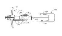
- FIG. 1is a perspective view of a preferred embodiment of an access device configured in accordance with the present invention and shows coaxially aligned needle, dilator, medical article, and guidewire.
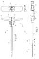
- FIG. 2Ais side view of a needle of the embodiment depicted in FIG. 1 .
- FIG. 2Bis a cross-sectional view of the needle of the embodiment depicted in FIG. 2A taken along line A-A.
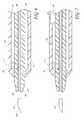
- FIG. 3Ais a side view of the dilator portion of the embodiment depicted in FIG. 1 .
- FIG. 3Bis a proximal end view of the dilator portion of FIG. 3A .
- FIG. 3Cis a cross-sectional view of the dilator portion of the embodiment depicted in FIG. 3A , taken along line B-B.
- FIG. 4Ais a side view of a sheath of the embodiment from FIG. 1 .
- FIG. 4Bis a proximal end view of the sheath of FIG. 4A .
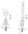
- FIG. 5is a side view of the access device of FIG. 1 .
- FIG. 6is an enlarged cross-sectional view of a portion the embodiment illustrated in FIG. 5 which is circled by line C-C.
- FIG. 7is a similar cross-sectional view of a portion of an access device which is configured in accordance with another preferred embodiment of present invention.
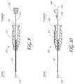
- FIG. 8is a similar cross-sectional view of a portion of an access device which is configured in accordance with an additional preferred embodiment of present invention.
- FIG. 9is an enlarged cross-sectional view of a needle hub with a guidewire extending therethrough, wherein the needle hub and the guidewire are configured in accordance with another preferred embodiment of the present invention.
- FIG. 10is an enlarged cross-sectional view of a needle hub with a guidewire extending therethrough, wherein the needle hub and the guidewire are configured in accordance with a further preferred embodiment of the present invention.
- FIG. 11is an enlarged cross-sectional view of a needle hub with a guidewire extending therethrough, wherein the needle hub and the guidewire are configured in accordance with an additional preferred embodiment of the present invention.
- FIG. 12is an enlarged view of a section of a guidewire configured in accordance with a further preferred embodiment of the present invention.
- FIG. 13is an enlarged view of a section of a guidewire configured in accordance with another preferred embodiment of the present invention.
- FIG. 14is an enlarged side view of a proximal end of an access device, including a guidewire with a release mechanism, which are configured in accordance with an additional embodiment of the present invention.
- FIG. 15is an enlarged side view of a proximal end of an access device that is configured in accordance with another embodiment of the present invention.
- FIG. 16is a side view of a guidewire configured in accordance with another embodiment of the present invention.
- the present disclosureprovides an access device for the delivery of a medical article, for example a catheter or sheath, to a blood vessel or drainage site that overcomes possible disadvantages associated with conventional non-surgical catheter insertion techniques.
- FIG. 1illustrates an access device 102 that is configured to be inserted into a blood vessel (e.g., a vein or an artery) in accordance with a preferred embodiment of the present invention. While the access device is described below in this context (i.e., for vascular access), the access device also can be used to access and place a medical article (e.g., catheter or sheath) into other locations within a patient's body (e.g., a drainage site) and for other purposes (e.g., for draining an abscess).
- a medical articlee.g., catheter or sheath
- the present embodiment of the access deviceis disclosed in the context of placing an exemplary single-piece, tubular medical article into a body space within a patient. Once placed, the tubular article can then be used to receive other medical articles (e.g., catheters, guidewires, etc.) to provide access into the body space, and/or used to provide a passage way for introducing fluids into the body space or removing (e.g., draining) fluids from the body space.
- the tubular medical articleis a sheath or catheter that is configured primarily to provide a fluid passage into a vein.
- the principles of the present inventionare not limited to the placement of single piece sheaths or catheters, or to the subsequent insertion of a medical article via the sheath or catheter.
- the access device disclosed hereinalso can be successfully utilized in connection with placing one or more other types of medical articles, including other types of sheaths, fluid drainage and delivery tubes, and single or multi-lumen catheters directly in the patient or indirectly via another medical article.
- the access device disclosed hereincan also be configured to directly or indirectly place central venous catheters, peripherally inserted central catheters, hemodialysis catheters, surgical drainage tubes, tear-away sheaths, multi-piece sheaths, scopes, as well as electrical conduit for wires or cables connected to external or implanted electronic devices or sensors.
- the medical articles listed abovemay be directly placed in the patient via the dilator, needle, and guidewire of the access device or subsequently placed within the patient via a medical article that was placed within the patient via the dilator, needle, and guidewire of the access device.
- the embodiments disclosed hereinare not limited to co-axial insertion of a single medical article.
- two cathetersmay be inserted in the patient via an inserted sheath or a second catheter may be inserted in the patient via an inserted first catheter.
- the medical article inserted via the dilator, needle, and guidewirecan form a lumen that is in addition to the lumen(s) of the subsequently inserted medical article.
- the illustration and description of the access device in connection with a sheathis merely exemplary of one possible application of the access device.
- the access device 102comprises a needle 20 , a dilator 28 , a sheath (e.g., catheter or cannula) 58 , and a guidewire 120 .
- the dilator 28is coaxially mounted on the needle 20
- the sheath 58is coaxially mounted on the dilator 28 .
- the needle 20 , dilator 28 , and sheath 58are releasably interlocked at the proximal end 110 of the access device 102 .
- the releasable interlock between the needle 20 , dilator 28 , and sheath 58is a linear interlock where the dilator 28 is locked to the needle 20 at interface 101 and the sheath 58 is locked to the dilator 28 at interface 103 .
- the needle 20locks to the dilator 28 via a lock mechanism 26 .
- the lock mechanism 26may comprise an engaging mechanism such as hinged clips 27 with clip sides 29 .
- the hinged clips 27may releasably engage and secure the dilator 28 to the needle 20 .
- the clip sides 29engage and secure the dilator 28 by clipping to the outer lip of a luer connection 33 on the dilator 28 .
- the lock member 26may comprise any suitable engaging mechanism known in the art.
- the portions of the outer lip onto which the hinge clips 27 engageare flats to inhibit rotation of the needle hub 21 relative to the dilator hub 32 after a certain degree of relative rotation (e.g., 180 degrees) between the needle hub 21 and the dilator hub 32 .
- the sheath 58is secured to the dilator 28 through a lock member 59 .
- the sheath 58may, preferably, comprise a twist lock member 59 so that the user may releasably engage and secure the dilator 28 to the sheath 58 .
- the dilator 28comprises teeth or prongs that are configured to mate or attach to corresponding areas on the sheath 58 .
- the needle 20 , dilator 28 and sheath 58are releasably locked so that a physician or user may remove sections or portions of the access device as needed for treatment.
- FIGS. 2A and 2Bdepict the needle 20 of the preferred embodiment shown in FIG. 1 .
- FIG. 2Ashows a side view of the needle 20 and
- FIG. 2Bprovides a cross-sectional view of the needle 20 .
- the needle 20has a needle body 22 , distal end 106 , and proximal portion 24 .
- the proximal portion 24has a needle hub 21 and the lock member 26 .
- the needle body 22preferably has an elongated tubular shape having a circular, constant-diameter inner bore and a circular, constant-diameter exterior surface. In other embodiments, however, the needle body 22 can have other bore and exterior shapes (such as, for example, but without limitation, an oval cross-sectional shape).
- the needle body 22has a sufficiently long length to access a targeted subcutaneous body space and has a sufficient gauge size to withstand the insertion forces when accessing the body space without causing undue trauma.
- the needle bodycan have a length between 3-20 cm, and more preferably between 3-10 cm.
- the needle body 22preferably has a length of 7 cm or greater, and more preferably has a length of 9 cm or greater, and most preferably has a length of 9 to 10 cm.
- the size of the needlepreferably is 18 gauge or smaller, and more preferably between 18-26 gauge, and most preferably between 18-26 gauge.
- the length and gauge of the needle body 22should be shorter and smaller, for example preferably between 3-4 cm and between 26-28 gauge.
- the needle body 22includes at least one fenestration or opening 34 near a distal end of the needle body 22 .
- the fenestration 34extends through the wall of the needle body 22 .
- the needle body 22can have a bevel tip 108 disposed on the distal portion 106 .
- the needle hub 21may also include locking structures at the proximal portion and distal portion of the needle hub 21 . These locking structures may be a luer-thread-type or another type of connections.
- a luer connection 35such a luer lock or slip, is disposed at the proximal portion 24 of the needle 20 . This allows the physician or healthcare provider, for example, to introduce a guidewire 120 through the hollow portion of the luer connection 35 , through the needle body 22 , and into a punctured vessel. Additionally, a physician or healthcare provider may also attach a syringe to the luer connection 35 to perform other procedures as desired.
- the needle hub 21comprises the lock member 26 .
- the lock member 26may be configured to lock or secure another part such as, for example, the dilator 28 or the sheath 58 , to the needle 20 .
- the lock member 26can comprise an engaging mechanism such as a pair of hinged clips 27 , although other types of locking mechanisms comprising tabs and/or slots can also be used.
- the clip sides 29 of the hinged clips 27can engage a lipped surface such as the outer lip 37 of a luer connection 33 to the dilator 28 , shown in FIG. 1 . Once engaged, the clip sides 29 prevent the locked part from undesired slipping or releasing.
- the clips 27are hinged to provide a bias towards the center of the needle hub 21 .
- the biasprevents the secured part from slipping or disengaging from the hinged clips 27 .
- the bias of the hinged clips 27can be overcome by simultaneously applying pressure to or squeezing the sides 29 of the clips 27 to release, for example, a luer connection to the luer connection 33 from the needle hub 21 .
- a physician or healthcare providermay, for example, place an index finger and thumb on the sides 29 of the hinged clips 27 and apply squeezing pressure to overcome the hinge bias.
- the hinged clips 27will, preferably, release only when sufficient releasing pressure is applied to both clip sides 29 .
- the needle proximal portion 24may have color coding, words, or other indicia, such as a pivot or notch, to indicate to the operator the position of the bevel tip 108 relative to the dilator 28 or the sheath 58 . Also, there may be a mechanical fit between the dilator 28 and the needle body 22 so that the physician or healthcare provider would sense by feel or sound (e.g., by a click) when the needle body 22 has been rotated to change the position of the bevel tip 108 .
- the needle body 22can be rotated relative to the dilator 28 and sheath 58 , so that the bevel tip 108 can be inserted into the blood vessel with bevel tip up, and can be rotated 180 degrees so that the bevel tip 108 is down after successful insertion. When the bevel tip 108 is in this position, it may be less likely that movement of the needle body 22 will cause injury to the blood vessel.
- FIGS. 3A , 3 B, and 3 Cprovide a side view of an entire dilator 28 , a side view of the dilator hub 32 from the proximal end 45 , and a cross-sectional view of a dilator 28 , respectively, for the embodiment described in FIG. 1 .
- the dilator 28may comprise a dilator shaft 30 and a dilator hub 32 .
- the dilator shaft 30may further comprise one or more side openings or fenestrations 111 .
- the dilator hub 32preferably comprises a luer connection 33 with an outer lip 37 . In some embodiments, the outer lip 37 can be configured to engage to a lock member 26 on the needle 20 .
- the dilator shaft 30may be coaxially mounted to the needle body 22 by slipping the hollow section 113 of the dilator shaft 30 over the needle body 22 and releasably securing the dilator hub 32 to the needle hub 21 .
- the proximal end 45 of the dilator hub 32is configured to mechanically fit and interlock with the needle lock member 26 to inhibit some rotational and axial motion.
- the dilator shaft 30is releasably mounted to the needle body 22 so that the dilator shaft 30 can be mounted and released, or vice versa, from a coaxial position relative to the needle body 22 .
- the dilator hub 32further comprises a locking mechanism 39 .
- the locking mechanism 39comprises posts, teeth, or prongs projecting from the dilator hub 32 . These teeth 39 can be configured to mate or attach to corresponding receiving areas disposed on another part such as the sheath 58 or the needle hub 21 . This locking mechanism 39 will be explained in greater detail in the following section.
- FIGS. 4A and 4Bshow side views of the medical article or sheath 58 illustrated in FIG. 1 .
- FIG. 4Bprovides a side view from the proximal end 57 .
- the medical articlepreferably, but not necessarily, includes a sheath 58 .
- the sheath 58comprises a sheath body 54 and a sheath hub 53 .
- the sheath body 54may be made partially or completely from a clear, translucent, semi-opaque, or transparent material.
- Such transparent, translucent, semi-opaque and clear materialsallow a clinician the ability to see when blood or other body fluids flows into the needle, through the needle side opening(s), through the side dilator opening(s), and into the viewing space between the dilator and sheath.
- the sheath body 54may be a single piece sheath through which a catheter or other medical article (e.g., a guidewire) is inserted into the vessel.
- the sheath body 54forms a conduit for insertion of the catheter or other medical article (e.g., a guidewire).
- the sheath or a portion of the sheathcan form a lumen that is in addition to the lumen(s) of the catheter.
- an equivalent to a triple lumen cathetercan be formed by inserting a dual lumen catheter through the sheath body 54 with the sheath body 54 itself forming a third lumen.
- the sheath hub 53may further comprise winged ends 55 and a lock member 59 .
- the lock member 59may comprise a locking or attaching structure that mates or engages with a corresponding structure.
- the lock member 59may comprise indentations, bumps, or grooves designed to engage and secure the teeth 39 on the dilator hub 32 described above in FIG. 2A .
- the sheath hub 53as best seen in FIGS. 4A and 4B , preferably is designed so that the teeth 39 of the dilator hub 32 can enter the sheath hub 53 substantially unobstructed. However, in use, once the sheath hub 53 is placed at a desired location over the dilator shaft 30 , the physician or healthcare provider can twist the sheath hub 53 and disengage the locking member 59 .
- the locking member 59can be, for example, a protruding bump, dent, etc., that creates a mechanical fit so that the dilator hub 32 and the sheath hub 53 are releasably interlocked.
- the locking member 59 of the sheath hub 53comprises a pair of axial arranged grooves which extend from an end of the sheath hub 53 and terminate at a protruding bump, dent, etc.
- the locked positioncan be disengaged by twisting the dilator hub 32 relative to the sheath hub 53 .
- the sheath hubmay comprise wings 55 or handle structures to allow for easy release and removal of the sheath body 54 from other parts.
- the wings 55are sized to provide the healthcare provider with leverage for breaking apart the sheath hub 53 .
- the sheath hub 53may comprise a thin membrane 61 connecting the halves of the sheath hub 53 .
- the membrane 61is sized to keep the halves of the sheath hub 53 together until the healthcare provider decides to remove the sheath hub 53 from the access device.
- the healthcare providermanipulates the wings 55 to break the membrane 61 and separate the sheath hub 53 into removable halves.
- sheath body 54It may be advantageous to remove a portion or the entire sheath body 54 depending on the type of catheter or medical article that is to be inserted into the vessel after employing the access device 102 .
- a portion of the sheath body 54can be separated or peeled-away and removed.
- a peel-away sheathcan include perforations, serrations, or other material structure to allow the physician or healthcare provider to easily remove a portion or the entire sheath body 54 .
- FIG. 5depicts a side view of the assembled access device 102 in which the needle 20 , dilator 28 , and sheath 58 are interlocked together.
- the needle 20 , dilator 28 and sheath 58are coaxially disposed about a common longitudinal axis.
- FIG. 6depicts a partial cross-sectional view of the assembled unit.
- the needle body 22preferably, comprises one or more side openings 34 in its side wall.
- the dilatormay comprise one or more side openings 111 .
- FIG. 6illustrates the alignment between only one set of corresponding side openings. Other sets of side openings can also be aligned or be misaligned depending upon the relative orientations of the needle 20 and the dilator 28 .
- the dilator shaft 30may be coaxially positioned to minimize the annular space 36 between the needle body 22 and the dilator shaft 30 .
- the inner surface 38 of the dilator shaft 30need not, though it can, lie directly against the outer-surface 40 of the needle body 22 .
- the annular interface 36 between the outer-surface 40 of the needle body 22 and the inner surface 38 of the dilator shaft 30is minimized to inhibit the flow of blood or its constituents (or other bodily fluids) into the annular interface 36 between the dilator shaft 30 and needle body 22 .
- this featureminimizes the blood's exposure to multiple external surfaces and reduces the risk of contamination, infection, and clotting.
- the sheath body 54is made partially or completely from clear, semi-opaque, translucent, or transparent material so that when blood flows into the needle body 22 , (1) through the needle side opening 34 , (2) through the dilator side opening 111 , and (3) into an annular space 60 between the dilator shaft 30 and the sheath body 54 , the physician or healthcare provider can see the blood. This will indicate to the physician or healthcare provider that the bevel tip 108 of the needle body 22 has punctured a blood vessel.
- the dilator shaft 30can be coaxially mounted to the needle body 22 such that at least one side opening 34 disposed on the needle body 22 is rotationally aligned with at least one side opening 111 on the dilator shaft 30 .
- the needle body 22 and dilator shaft 30may (both) have multiple side openings 34 , 111 where some or all of these side openings 34 , 111 can be rotationally aligned.
- the needle body 22 and dilator shaft 30maintain rotational alignment so that blood flows substantially unobstructed through the needle side opening 34 and dilator side opening 111 .
- the dilator shaft 30 and needle body 22maintain releasable rotational alignment where the user may transition the dilator shaft 30 and needle body 22 from a first annular position to a second annular position about the longitudinal axis relative to the needle body 22 .
- the transition from a first to second positionmay align or misalign the respective side openings on the needle body 22 and dilator shaft 30 .
- This featureallows the user to change the needle body 22 to a desired orientation before and/or after puncturing the blood vessel.
- rotating the bevel tip 108 180 degreesprevents risk of unwanted injury to the vessel.
- the physician or healthcare providercan alter the rotational alignment between the dilator shaft 30 and needle body 22 according to his/her needs.
- FIG. 7depicts a cross-sectional view of another preferred embodiment of the present invention.
- the annular space 60 between the dilator shaft 30 and sheath body 54may be minimized to reduce the flow of blood into this space 60 .
- a passageway or conduit 62is provided that channels blood flow to a view space 43 .
- a groove formed (e.g., by scoring) on either the outer side of the dilator shaft 30 or the inner side of the sheath body 54can define at least a portion of the passageway or conduit 62 .
- the passageway or conduit 62 and the view space 43reduce the open space in the annular space 60 into which the blood or fluid can flow.
- FIG. 8depicts a cross-sectional view of another preferred embodiment of the present invention.
- the annular space 60can be substantially restricted so that blood or its constituents cannot flow into the annular space between the sheath body 54 and the dilator shaft 30 .
- the sheathpreferably, comprises a view space 43 that allows some blood to flow into a substantially reduced space between the dilator shaft 30 and sheath body 54 .
- bloodcannot flow from the view space 43 or side openings 34 , 111 into the annular space 60 .
- the portion of the sheath body 54 above the view space 43can be made from a clear, semi-opaque, translucent, or transparent material so that when blood flows into the needle body 22 , through the needle side opening 34 , through the dilator side opening 111 , and into the view space 43 , the physician or healthcare provider can see the blood.
- the dilator side opening 111 , needle side opening 34 , and the view space 43are rotationally aligned so that the blood can flow through the needle side opening 34 , through the dilator side opening 111 , and into the view space 43 without any substantial obstruction.
- the sheathmay comprise more than one view space 43 .
- the side openings 34 , 111 in the needle 20 and the dilator shaft 30are aligned in the embodiments illustrated in FIGS. 6 , 7 and 8 , the side openings alternatively can overlap with each other or can be connected via a passageway or conduit 62 .
- the passageway or conduit 62can be formed between the side openings 111 , 34 in the dilator and the needle.
- the passageway or conduit 62is defined by one or more grooves that are formed (e.g., by scoring) on an outer side surface of the needle, on an inner side surface of the dilator, or on both the needle outer side surface and the dilator inner side surface.
- the groovescan oppose each other or can overlap at one or more points to define a portion of the passageway.
- the passageway or conduit 62 that places the side openings in communicationcan be formed by incongruous shapes (e.g., incongruous radial cross-sectional shapes) between the needle outer surface and the dilator inner surface.
- the needle outer surfacecan have a circular shape and the dilator inner surface can have an oval shape with a minor dimension of the oval substantially equals the diameter to the circle, or vise versa.
- the needle outer surface and the dilator inner surfacealso can have other incongruous shapes, such as, but without limitation, a triangle and a circle, a square and a circle, and a square and a triangle, where the needle supports the dilator at least at two points.
- an interlock or interconnection between the guidewire and at least one of the following components of the access device(1) the needle body; (2) the needle hub; and (3) the dilator hub.
- the interlock or interconnectioninhibits the proximal end of the guidewire from being advanced too far into the needle (and risk the possibility of intravascular guidewire loss), as well as allows the needle, the dilator and the guidewire to be generally withdrawn simultaneously. Additionally, by inhibiting the withdrawal of the advanced guidewire back into the needle, the risk of shearing off the distal end of the guidewire and having a guidewire embolus is reduced.
- the interlock or interconnectioncan also ensure that the distal end of the guidewire remains extended beyond the distal end of the needle to protect the needle tip, thereby inhibiting an accidental needle stick.
- FIG. 9illustrates an embodiment of an interconnection suitable to couple the guidewire 120 with the needle hub 21 once a healthcare provider has advanced the guidewire 120 to its fully deployed position (i.e., to a position where the guidewire 120 extends well beyond the distal end 108 of the needle body 22 into the vessel).
- the interconnectioncomprises a female luer or inner bore 130 defined by the inner bore of the needle hub 21 and a male luer 122 disposed on the guidewire 120 .
- the male luer 122preferably resided at the proximal end of the guidewire 120 ; however, it can be formed at other locations along the guidewire's length, provided a sufficient length of guidewire 120 extends into the vascular lumen (or other body cavity, lumen or space) when the male luer 122 engages the female luer 130 .
- the male luer 122can be molded (e.g., inserted molded), crimped, adhered or otherwise attached onto or to the end of the guidewire 120 or can be formed in a unitary manner with the guidewire 120 .
- the male luer body 122can be molded as a separate piece with a hole passing through the luer body 122 .
- the holecan be created in the molding process or can be created thereafter.
- the luer body 122is then threaded over the guidewire 120 .
- the proximal end of the guidewirecan be crimped, kinked, or enlarged by the addition of other material to inhibit the luer body 122 from slipping off the proximal end of the guidewire 120 .
- the guidewire 120can be similarly modified at a point distal of the luer body 122 to inhibit the luer body 122 from sliding distally and ease the use of the device; however, such further modification is unnecessary in order to interconnect together the needle hub 21 and guidewire 120 when the guidewire 120 is fully deployed.
- the male and female luer connection illustrated in FIG. 9is but one example of the types of cooperating structure that can be included to interconnect or interlock the guidewire 120 with the needle hub 21 .
- Other types of interengaging structurecan also be used for this purpose.
- the guidewire 120can include one or more enlarged beads at or near its proximal end and the needle hub 21 can include one or more annular grooves defined about its conical inner bore 130 . When advancing the guidewire 120 to its fully extended position, the bead snaps into the corresponding annular groove to interlock the guidewire 120 to the needle hub 21 .
- the engagement between the guidewire 120 and the needle hub 21can occur through simple axial movement of the guidewire 120 relative to the needle hub 21 , as understood from the embodiments described above. It can also occur through relative rotational movement between the guidewire 120 and the needle hub 21 , or though a combination of both axial and rotational movements.
- the male luer 122which is included on the end of the guidewire 120 , can include one or more projecting structures (e.g., an external thread) that engage one or more spiral grooves (e.g., an internal thread) formed within the needle hub 21 .
- a combined axial and rotational movement of the guidewire 120 relative to the needle hub 21will interengage these cooperating structures to interlock the guidewire 120 and the needle hub 21 .
- FIG. 10illustrates another interlock formed between the guidewire 120 and the needle hub 21 .
- the proximal end of the guidewire 120is shaped as a clip 140 , which is configured to engage structure on the needle hub 21 .
- the clip 140has a two-dimensional shape; however, in other embodiments, the clip can take a three-dimensional shape.
- the clip 140is preferably configured to engage an annular flange 142 disposed at the end of the needle hub 21 .
- the clip 140includes a transverse section 144 that extends outwardly from a longitudinal axis of the guidewire 120 and lies generally normal to the longitudinal axis; however, the transverse section 144 can extend at an acute or oblique angle relative to the longitudinal axis of the guidewire 120 .
- the length of the transverse sectionpreferably is slightly larger than half of the diameter across the hub flange 142 .
- the clip 140also includes a spring clip 146 that extends distally from the transverse section 144 .
- the spring clip 146includes a generally V-shaped end that is configured to deflect outwardly and ride over the hub flange 142 when the guidewire 120 is advanced distally and then to spring back toward the guidewire 120 and into a groove or space provided on a distal side of the hub flange 142 .
- the spring clip 146can include an abutment surface on an inner side of the spring clip 146 , which extends generally normal to the longitudinal axis and is disposed to abut against a distal side of the hub flange 142 to resist proximal movement of the guidewire 120 relative to the needle hub 21 .
- FIG. 11illustrates an example of an interlock formed between the guidewire 120 and the needle body 22 .
- the interlockis formed in part by a hole 150 through the needle body 22 .
- hub material on either side of the through hole 150is also omitted; however, such a relief may not be included in other embodiments. Additionally, the hole 150 need not extend through the needle body 22 .
- the guidewire 120includes a protuberance 152 (e.g., a bead) formed along its length which is deformable and is slightly larger than the inner diameter of the needle body 22 .
- the protuberance 152may be integral with the guidewire 120 or be attached to the guidewire 120 .
- the protuberance 152can also take the form of a deflectable barb that projects proximally from the guidewire 120 to inhibit proximal movement once it engages with the through hole 150 . Additional protuberances are depicted in FIGS. 12 and 13 .
- the protuberance 152 bis formed by flattening a section of the guidewire 120 .
- FIG. 12the protuberance 152 b is formed by flattening a section of the guidewire 120 .
- the protuberance 152 cis formed by a pair of nubs 154 formed on opposite sides of the guidewire 120 .
- the guidewireis split to a point distal of the nubs and plastically deformed so as to spread the nubs 154 apart.
- the split ends 156 of the guidewire 120act as leaf springs that bias the nubs 154 outwardly, away from a longitudinal axis of the guidewire 120 .
- the protuberance 152is sized and located on the guidewire 120 to interact with the through hole 150 once the guidewire 120 has been advanced into the vessel by a desired length. At this point, the protuberance 152 snaps or springs into one or both sides of the through hole 150 to hold the guidewire 120 relative to the needle body 22 .
- the guidewire 120can also include a plurality of protuberances so as to provide multiple extension lengths for the guidewire 120 from the needle body 22 and/or to interact with a plurality of through holes to provide enhanced or redundant interengagement between the guidewire 120 and the needle body 22 .
- FIG. 14illustrates a further embodiment of an interlock between the guidewire 120 and the needle hub 21 with the addition of a release mechanism that unlocks the dilator shaft 30 (and the sheath body 54 in the illustrated embodiment) from the needle hub 21 .
- the proximal end of the guidewire 120is attached to an end cap 160 that interacts with the needle hub 21 in any of the variety of ways described above.
- the end cap 160additionally includes a pair of cam arms 162 .
- the cam arms 162when the end cap 160 is engaged with the needle hub 21 , cause the clip sides 29 to depress inward and release the hinged clips 27 from the flange 33 of the dilator hub 32 . In this position, the guidewire 120 is interlocked or interconnected with the needle hub 21 , while the dilator shaft 30 is free to be advanced over the needle body 22 .
- FIG. 15illustrates a further embodiment of an access device that includes an interconnection between the guidewire 120 and the needle hub 21 , which also helps support a length of guidewire 120 before insertion into the needle body 22 .
- a support rod 170extends proximally from the needle hub 21 .
- the length of the rod 170can generally equal the length of the guidewire 120 and in other embodiments it can be significantly shorter (e.g., 25%-50% of the guidewire's length).
- the guidewire 120includes a loop 172 formed at or near its proximal end which slides over the rod 170 as the guidewire 120 is advanced into the needle body 22 . The interaction between the loop 172 and the rod support 170 supports the proximal end of the guidewire 120 .
- the loopcan be part of the rod and the guidewire is placed within that loop, reducing the likelihood that the wire will fall out of the device before or during the procedure.
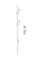
- FIG. 16illustrates another embodiment of a guidewire 120 that can be used with one or more of the above-described embodiments of the access device.
- the guidewire 120has one or more movable positioners or stops 180 that can be slid along the guidewire shaft 120 as desired to limit the forward advancement or backward movement of the guidewire 120 within the assembly of the needle 20 , the dilator 28 , and the sheath 58 .
- the stops 180are silicone balls.
- the stop(s)of course can have other shapes as well such as, for example, but without limitation, a hollow cylindrical shape or a hollow truncated conical shape (e.g., substantially matching the shape of the needle hub inner bore), and can be made of other types of materials as well.
- Each ball 180 in the illustrated embodimenthas a bore 182 passing through the ball 180 .
- the bore 182has a diameter approximately equal to the diameter of the guidewire 120 .
- the compressible nature of the silicone balls 180allows them to be slid under force to a desired location along the guidewire's length. Once a sufficient sliding force is no longer applied, the interference and resulting friction between the balls 180 and the guidewire 120 inhibits the balls 180 from sliding over the guidewire 120 .
- one or more of the stops 180can be split along its length (e.g., by a groove, slit, or elongated opening) that permits the stop to be attached and detached from the guidewire 120 without passing over an end of the guidewire 120 .
- This configurationthus allows the stop(s) 180 to be removed from guidewires with outwardly-extending proximal structure (e.g., the guidewires 120 shown in FIGS. 9 , 10 , 14 and 15 ) without passing over either the proximal or distal ends of the guidewire.
- proximal structuree.g., the guidewires 120 shown in FIGS. 9 , 10 , 14 and 15
- the outer diameter of the balls 180is sized to be larger than the proximal opening into the needle body 22 .
- the outer size of the ball 180is larger than an inner bore 130 of the needle hub 21 ; however, in other embodiments, the ball 180 can be sized to fit within the inner bore 130 but not to fit into the needle body 22 .
- the resulting interference between the stop 180 and the needle hub 21 and/or the needle body 22limits the forward advancement of the guidewire 120 into the needle 20 , as well as inhibits retraction (backwards movement) of the guidewire 120 from the needle body 22 .
- the balls 180also support the guidewire 120 when the access device 102 is placed in its packaging, and inhibit the guidewire 120 from moving relative to the needle/dilator/sheath assembly during sterilization, transport and storage, prior to use.
- the needlepreferably consists of a rigid polymer or a metal such as stainless steel, nitinol, or the like.
- the other elementscan be formed of suitable polymeric materials, such as polycarbonate, nylon, polyethylene, high-density polyethylene, polypropylene, fluoropolyrners and copolymers such as perfluoro (ethylene-propylene) copolymer, polyurethane polymers or co-polymers.
- the present access devicecan be used to place a catheter at other locations within a patient's body.
- the access devicecan be used as or with a variety of catheters to drain fluids from abscesses, to drain air from a pneurnotorax, and to access the peritoneal cavity.
- body fluidsflow into the viewing space to indicate when the needle has been properly placed.
Landscapes
- Health & Medical Sciences (AREA)
- Life Sciences & Earth Sciences (AREA)
- Animal Behavior & Ethology (AREA)
- Veterinary Medicine (AREA)
- Public Health (AREA)
- Engineering & Computer Science (AREA)
- Biomedical Technology (AREA)
- Heart & Thoracic Surgery (AREA)
- General Health & Medical Sciences (AREA)
- Anesthesiology (AREA)
- Pulmonology (AREA)
- Biophysics (AREA)
- Hematology (AREA)
- Surgery (AREA)
- Gastroenterology & Hepatology (AREA)
- Nuclear Medicine, Radiotherapy & Molecular Imaging (AREA)
- Pathology (AREA)
- Medical Informatics (AREA)
- Molecular Biology (AREA)
- Media Introduction/Drainage Providing Device (AREA)
- Surgical Instruments (AREA)
- Accommodation For Nursing Or Treatment Tables (AREA)
- Infusion, Injection, And Reservoir Apparatuses (AREA)
Abstract
Description
Claims (58)
Priority Applications (2)
| Application Number | Priority Date | Filing Date | Title |
|---|---|---|---|
| US12/106,119US8192402B2 (en) | 2007-04-18 | 2008-04-18 | Access device |
| US13/466,933US20120283640A1 (en) | 2007-04-18 | 2012-05-08 | Access device |
Applications Claiming Priority (3)
| Application Number | Priority Date | Filing Date | Title |
|---|---|---|---|
| US91264507P | 2007-04-18 | 2007-04-18 | |
| US94813607P | 2007-07-05 | 2007-07-05 | |
| US12/106,119US8192402B2 (en) | 2007-04-18 | 2008-04-18 | Access device |
Related Child Applications (1)
| Application Number | Title | Priority Date | Filing Date |
|---|---|---|---|
| US13/466,933DivisionUS20120283640A1 (en) | 2007-04-18 | 2012-05-08 | Access device |
Publications (2)
| Publication Number | Publication Date |
|---|---|
| US20080262430A1 US20080262430A1 (en) | 2008-10-23 |
| US8192402B2true US8192402B2 (en) | 2012-06-05 |
Family
ID=39735282
Family Applications (2)
| Application Number | Title | Priority Date | Filing Date |
|---|---|---|---|
| US12/106,119Active2031-03-30US8192402B2 (en) | 2007-04-18 | 2008-04-18 | Access device |
| US13/466,933AbandonedUS20120283640A1 (en) | 2007-04-18 | 2012-05-08 | Access device |
Family Applications After (1)
| Application Number | Title | Priority Date | Filing Date |
|---|---|---|---|
| US13/466,933AbandonedUS20120283640A1 (en) | 2007-04-18 | 2012-05-08 | Access device |
Country Status (4)
| Country | Link |
|---|---|
| US (2) | US8192402B2 (en) |
| EP (3) | EP2150187A2 (en) |
| JP (1) | JP2010524586A (en) |
| WO (1) | WO2008131289A2 (en) |
Cited By (66)
| Publication number | Priority date | Publication date | Assignee | Title |
|---|---|---|---|---|
| US20100152613A1 (en)* | 2008-12-11 | 2010-06-17 | Shawn Ryan | Clip for handling an endoscopic device |
| US20110009832A1 (en)* | 2005-09-22 | 2011-01-13 | Tyco Healthcare Group Lp | Non-Axial Return Spring for Safety Needle |
| US20120010643A1 (en)* | 2009-04-03 | 2012-01-12 | Weixing Shao | Puncture needle for orthopedic operation |
| US20130066276A1 (en)* | 2010-06-04 | 2013-03-14 | Jms Co., Ltd. | Indwelling needle device |
| US20140088560A1 (en)* | 2011-03-30 | 2014-03-27 | Cornell University | Intra-luminal access apparatus and methods of using the same |
| US8827958B2 (en) | 2009-05-12 | 2014-09-09 | Access Scientific, Llc | Access device with valve |
| US8900192B2 (en) | 2007-04-18 | 2014-12-02 | Access Scientific, Llc | Access device |
| US8915884B2 (en) | 2007-01-24 | 2014-12-23 | Access Scientific, Inc. | Access device |
| US8956327B2 (en) | 2010-02-08 | 2015-02-17 | Access Scientific, Llc | Access device |
| US9138252B2 (en) | 2008-03-14 | 2015-09-22 | Access Scientific, Llc | Access device |
| US20160000454A1 (en)* | 2011-04-11 | 2016-01-07 | The Spectranetics Corporation | Needle and guidwire holder |
| US20160030716A1 (en)* | 2013-03-14 | 2016-02-04 | The University Of Utah Research Foundation | Needle in catheter cannulation systems and methods |
| US20160089180A1 (en)* | 2014-09-30 | 2016-03-31 | Fateh Entabi | Surgical tools and system for safely accessing body cavities and methods of using the same |
| US9522254B2 (en) | 2013-01-30 | 2016-12-20 | Vascular Pathways, Inc. | Systems and methods for venipuncture and catheter placement |
| US9566087B2 (en) | 2013-03-15 | 2017-02-14 | Access Scientific, Llc | Vascular access device |
| US9616201B2 (en) | 2011-01-31 | 2017-04-11 | Vascular Pathways, Inc. | Intravenous catheter and insertion device with reduced blood spatter |
| US9675784B2 (en) | 2007-04-18 | 2017-06-13 | Vascular Pathways, Inc. | Intravenous catheter insertion and blood sample devices and method of use |
| US9808598B2 (en) | 2015-02-04 | 2017-11-07 | Teleflex Medical Incorporated | Flexible tip dilator |
| US9861792B2 (en) | 2011-02-25 | 2018-01-09 | C. R. Bard, Inc. | Medical component insertion device including a retractable needle |
| US9872971B2 (en) | 2010-05-14 | 2018-01-23 | C. R. Bard, Inc. | Guidewire extension system for a catheter placement device |
| US9884169B2 (en) | 2011-08-17 | 2018-02-06 | Access Scientific, Llc | Access device with valve |
| US9950139B2 (en) | 2010-05-14 | 2018-04-24 | C. R. Bard, Inc. | Catheter placement device including guidewire and catheter control elements |
| US9981113B2 (en) | 2012-03-14 | 2018-05-29 | Access Scientific, Llc | Flexible medical article and method of making the same |
| US10220191B2 (en) | 2005-07-06 | 2019-03-05 | Vascular Pathways, Inc. | Intravenous catheter insertion device and method of use |
| US10232146B2 (en) | 2014-09-05 | 2019-03-19 | C. R. Bard, Inc. | Catheter insertion device including retractable needle |
| EP3349849A4 (en)* | 2015-09-15 | 2019-07-10 | Custom Medical Applications, Inc. | DEPLOYMENT DEVICES AND ASSEMBLIES AND ASSOCIATED METHODS |
| US10384039B2 (en) | 2010-05-14 | 2019-08-20 | C. R. Bard, Inc. | Catheter insertion device including top-mounted advancement components |
| USD865165S1 (en) | 2013-11-25 | 2019-10-29 | Custom Medical Applications, Inc. | Medical device anchor |
| US10493262B2 (en) | 2016-09-12 | 2019-12-03 | C. R. Bard, Inc. | Blood control for a catheter insertion device |
| US10569059B2 (en) | 2018-03-01 | 2020-02-25 | Asspv, Llc | Guidewire retention device |
| US10675446B2 (en) | 2012-03-14 | 2020-06-09 | Asspv, Llc | Flexible medical article and method of making the same |
| USD903100S1 (en) | 2015-05-01 | 2020-11-24 | C. R. Bard, Inc. | Catheter placement device |
| USD903101S1 (en) | 2011-05-13 | 2020-11-24 | C. R. Bard, Inc. | Catheter |
| USD904625S1 (en) | 2020-05-08 | 2020-12-08 | Smiths Medical Asd, Inc. | Device for trimming a medical article |
| US10869689B2 (en) | 2017-05-03 | 2020-12-22 | Medtronic Vascular, Inc. | Tissue-removing catheter |
| US11000678B2 (en) | 2010-05-14 | 2021-05-11 | C. R. Bard, Inc. | Catheter placement device and method |
| USD921884S1 (en) | 2018-07-27 | 2021-06-08 | Bard Access Systems, Inc. | Catheter insertion device |
| US11027099B2 (en) | 2015-04-30 | 2021-06-08 | Smiths Medical Asd, Inc. | Vascular access device |
| US11040176B2 (en) | 2015-05-15 | 2021-06-22 | C. R. Bard, Inc. | Catheter placement device including an extensible needle safety component |
| US11389626B2 (en) | 2018-03-07 | 2022-07-19 | Bard Access Systems, Inc. | Guidewire advancement and blood flashback systems for a medical device insertion system |
| US11389624B2 (en) | 2020-11-26 | 2022-07-19 | Avia Vascular, Llc | Blood collection devices, systems, and methods |
| US11400260B2 (en) | 2017-03-01 | 2022-08-02 | C. R. Bard, Inc. | Catheter insertion device |
| US11517719B2 (en) | 2019-09-24 | 2022-12-06 | Bard Access Systems, Inc. | Integrated acute central venous catheter and peripherally inserted venous catheter |
| US11559665B2 (en) | 2019-08-19 | 2023-01-24 | Becton, Dickinson And Company | Midline catheter placement device |
| US11690645B2 (en) | 2017-05-03 | 2023-07-04 | Medtronic Vascular, Inc. | Tissue-removing catheter |
| US11819236B2 (en) | 2019-05-17 | 2023-11-21 | Medtronic Vascular, Inc. | Tissue-removing catheter |
| US11819638B2 (en) | 2020-05-21 | 2023-11-21 | Bard Access Systems, Inc. | Rapidly insertable central catheters including catheter assemblies and methods thereof |
| US11826526B2 (en) | 2020-01-23 | 2023-11-28 | Bard Access Systems, Inc. | Splitable catheter docking station system and method |
| US11839735B2 (en) | 2017-04-14 | 2023-12-12 | Smiths Medical Asd, Inc. | Vascular access device |
| US11890429B2 (en) | 2019-09-10 | 2024-02-06 | Bard Access Systems, Inc. | Rapidly inserted central catheter and methods thereof |
| US11918767B2 (en) | 2020-04-23 | 2024-03-05 | Bard Access Systems, Inc. | Rapidly insertable central catheters including catheter assemblies and methods thereof |
| US11925779B2 (en) | 2010-05-14 | 2024-03-12 | C. R. Bard, Inc. | Catheter insertion device including top-mounted advancement components |
| US11944349B2 (en) | 2021-02-25 | 2024-04-02 | Terumo Medical Corporation | Adjustable vascular closure device assembly |
| US12064576B2 (en) | 2020-03-13 | 2024-08-20 | Bard Access Systems, Inc. | Guidewire-management devices and methods thereof |
| US12097342B2 (en) | 2015-01-29 | 2024-09-24 | Becton, Dickinson And Company | Rapid insertion integrated catheter and method of using an integrated catheter |
| US12138405B2 (en) | 2020-12-17 | 2024-11-12 | Bard Access Systems, Inc. | Rapidly insertable central catheters, assemblies, and methods thereof |
| US12161820B2 (en) | 2020-06-29 | 2024-12-10 | Bard Access Systems, Inc. | Rapidly insertable central catheters including catheter assemblies and methods thereof |
| US12186496B2 (en) | 2017-05-26 | 2025-01-07 | Avia Vascular, Llc | Catheter delivery devices, systems, and methods |
| US12186494B2 (en) | 2020-03-13 | 2025-01-07 | Bard Access Systems, Inc. | Guidewire-management devices and methods thereof |
| US12186503B2 (en) | 2019-10-25 | 2025-01-07 | Bard Access Systems, Inc. | Guidewire-management devices and methods thereof |
| US12263316B2 (en) | 2020-12-21 | 2025-04-01 | Bard Access Systems, Inc. | Fluid path optimization in catheter insertion systems |
| US12274836B2 (en) | 2020-06-29 | 2025-04-15 | Bard Access Systems, Inc. | Rapidly insertable central catheters including assemblies and methods thereof |
| US12290644B2 (en) | 2020-10-28 | 2025-05-06 | Bard Access Systems, Inc. | Catheter placement system with stiffening system |
| US12329418B2 (en) | 2022-07-26 | 2025-06-17 | Globus Medical Inc. | Minimally invasive surgery guide wire capturing instrumentation |
| US12357794B2 (en) | 2020-12-21 | 2025-07-15 | Bard Access Systems, Inc. | Optimized structural support in catheter insertion systems |
| US12440652B2 (en) | 2019-09-20 | 2025-10-14 | Bard Peripheral Vascular, Inc. | Intravenous catheter-placement device and method thereof |
Families Citing this family (60)
| Publication number | Priority date | Publication date | Assignee | Title |
|---|---|---|---|---|
| DE60235574D1 (en)* | 2001-12-26 | 2010-04-15 | Univ Yale | VESSEL shunt device |
| EP1876972A4 (en)* | 2005-03-30 | 2009-04-01 | Access Scientific Inc | Vascular access |
| USD601242S1 (en) | 2008-03-14 | 2009-09-29 | Access Scientific, Inc. | Access device |
| EP2319576A1 (en)* | 2008-03-14 | 2011-05-11 | Access Scientific, Inc. | Access device |
| US20100010505A1 (en)* | 2008-07-11 | 2010-01-14 | Herlihy J Patrick | Methods and apparatus for introducing a medical device into the body of a patient |
| USD614296S1 (en)* | 2008-09-11 | 2010-04-20 | Ispg, Inc. | Needle hub |
| WO2010031064A1 (en)* | 2008-09-15 | 2010-03-18 | Clearview Patient Safety Technologies, Llc | Lumbar puncture detection device |
| US9566053B2 (en)* | 2009-12-04 | 2017-02-14 | James K Brannon | Cannula positioned targeting guide |
| EP3659490B1 (en)* | 2010-08-20 | 2025-10-01 | Veran Medical Technologies, Inc. | Apparatus and method for four dimensional soft tissue navigation |
| EP2428189A1 (en) | 2010-09-10 | 2012-03-14 | Symetis Sa | Catheter delivery system for stent valve |
| US8805519B2 (en) | 2010-09-30 | 2014-08-12 | Nevro Corporation | Systems and methods for detecting intrathecal penetration |
| US8965482B2 (en) | 2010-09-30 | 2015-02-24 | Nevro Corporation | Systems and methods for positioning implanted devices in a patient |
| US20140088516A1 (en)* | 2011-01-04 | 2014-03-27 | Jon R. Stevenson | Visually size-gauging hollow needle assembly |
| WO2012117028A2 (en) | 2011-03-01 | 2012-09-07 | Dangoisse Vincent | Vascular needle system |
| WO2012135761A1 (en)* | 2011-04-01 | 2012-10-04 | Access Scientific, Inc. | Access device |
| KR20140087032A (en) | 2011-10-31 | 2014-07-08 | 유타카 스즈키 | Medical dilating instrument and medical dilating instrument set |
| US9561347B2 (en)* | 2011-11-16 | 2017-02-07 | W. L. Gore & Associates, Inc. | Introducer sheath assembly having a locking dilator |
| US9533120B1 (en)* | 2011-12-02 | 2017-01-03 | Greatbatch Ltd. | Transseptal needle assembly |
| US9149606B2 (en) | 2011-12-09 | 2015-10-06 | Teleflex Medical Incorporated | Enhanced introducer assembly |
| EP2816966B1 (en) | 2012-02-22 | 2023-10-25 | Veran Medical Technologies, Inc. | Steerable surgical catheter comprising a biopsy device at the distal end portion thereof |
| US9566413B2 (en)* | 2012-03-23 | 2017-02-14 | Terumo Medical Corporation | Dilator centering device and assemblies |
| US9358039B2 (en) | 2012-05-08 | 2016-06-07 | Greatbatch Ltd. | Transseptal needle apparatus |
| US8986264B2 (en)* | 2012-05-08 | 2015-03-24 | Greatbatch Ltd. | Transseptal needle apparatus |
| HK1221673A1 (en)* | 2012-10-02 | 2017-06-09 | 女王医疗中心 | Vascular access system having a guidewire anti-migration feature |
| US10258774B2 (en) | 2012-10-31 | 2019-04-16 | Teleflex Medical Incorporated | Smart 3-way valve with high and low pressure sensing |
| US9308022B2 (en) | 2012-12-10 | 2016-04-12 | Nevro Corporation | Lead insertion devices and associated systems and methods |
| CN109009355B (en)* | 2012-12-28 | 2021-07-20 | 心诺普医疗技术(北京)有限公司 | Pericardium puncture needle assembly |
| JP6356148B2 (en)* | 2013-01-03 | 2018-07-11 | サミット・アクセス・エルエルシー | Composite wire and related methods for use in medical procedures |
| CN105658255B (en)* | 2013-05-10 | 2019-01-08 | 卡恩技术佛罗里达有限公司 | Transjugular intrahepatic portosystemic shunt device |
| US9265935B2 (en) | 2013-06-28 | 2016-02-23 | Nevro Corporation | Neurological stimulation lead anchors and associated systems and methods |
| CN104434271A (en)* | 2013-09-13 | 2015-03-25 | 李鹏 | Puncture needle special for children inguinal hernia sac high ligation |
| CN103638588B (en)* | 2013-12-18 | 2015-10-28 | 南京市妇幼保健院 | A kind of drainage device for safe puncture |
| US11389195B2 (en)* | 2014-01-24 | 2022-07-19 | Medtronic, Inc. | Implant tools for extra vascular implantation of medical leads |
| US20150305650A1 (en) | 2014-04-23 | 2015-10-29 | Mark Hunter | Apparatuses and methods for endobronchial navigation to and confirmation of the location of a target tissue and percutaneous interception of the target tissue |
| US20150305612A1 (en) | 2014-04-23 | 2015-10-29 | Mark Hunter | Apparatuses and methods for registering a real-time image feed from an imaging device to a steerable catheter |
| US9789321B2 (en) | 2015-04-03 | 2017-10-17 | Nevro Corp. | Couplings for implanted leads and external stimulators, and associated systems and methods |
| US10792465B2 (en) | 2015-05-15 | 2020-10-06 | Merit Medical Systems, Inc. | Quick-release hubs for medical devices |
| CN105013042B (en)* | 2015-07-31 | 2017-10-31 | 中国医科大学附属第一医院 | Stem cell continuous injection system in minimally invasive coronary artery bypass graft |
| JP2018537162A (en)* | 2015-11-03 | 2018-12-20 | ザ・ジェネラル・ホスピタル・コーポレイションThe General Hospital Corporation | System, method and apparatus for selectively accessing an internal lumen of a patient's blood vessel |
| US10806904B2 (en)* | 2016-03-31 | 2020-10-20 | Surmodics, Inc. | Two-part insertion tool and methods |
| CN105902304A (en)* | 2016-05-27 | 2016-08-31 | 武夷山捷安医疗器械制造有限公司 | Conical tip type deep vein puncture needle |
| CA3032247A1 (en)* | 2016-08-03 | 2018-02-08 | Vascular Barcelona Devices, S.L. | Catheter devices, needle assemblies and kits |
| CN106618686A (en)* | 2016-10-24 | 2017-05-10 | 常熟市第人民医院 | Combined spinal anaesthesia and dura mater puncture needle with three-dimensional relatively-fixed rotatable wing |
| US10980999B2 (en) | 2017-03-09 | 2021-04-20 | Nevro Corp. | Paddle leads and delivery tools, and associated systems and methods |
| CN117898800A (en) | 2017-10-12 | 2024-04-19 | 波士顿科学医疗设备有限公司 | Medical device assembly |
| EP3697489A4 (en)* | 2017-10-20 | 2021-09-08 | Smiths Medical ASD, Inc. | CATHETER WITH THREADING FLASH CONFIRMATION |
| WO2019191423A1 (en) | 2018-03-29 | 2019-10-03 | Nevro Corp. | Leads having sidewall openings, and associated systems and methods |
| US11517722B2 (en)* | 2019-01-18 | 2022-12-06 | Becton, Dickinson And Company | Confirmation of catheter placement within a vein |
| US11383066B2 (en)* | 2019-02-05 | 2022-07-12 | Virginia Commonwealth University | Guidewire systems and methods for preventing wire advancement into the body during catheterization |
| EP3877032A4 (en)* | 2019-04-12 | 2022-01-19 | Teleflex Medical Incorporated | Catheter insertion apparatus with continuous visible flashback |
| KR20220021468A (en)* | 2019-04-29 | 2022-02-22 | 베이리스 메디컬 컴퍼니 아이엔씨. | Transseptal system, device and method |
| WO2020256642A1 (en)* | 2019-06-21 | 2020-12-24 | Singapore Health Services Pte Ltd | A guidewire management device |
| US11617863B2 (en)* | 2019-10-19 | 2023-04-04 | Anthony DiCianni | Intravenous catheter and guidewire advancement mechanism |
| CN110897688A (en)* | 2019-12-27 | 2020-03-24 | 上海长征医院 | A guidewire-needle integrated arteriovenous puncture device that can be operated with one hand |
| WO2021183268A1 (en)* | 2020-03-10 | 2021-09-16 | Boston Scientific Scimed, Inc. | Device, a system, and a method for access cannula advancement |
| WO2021202558A1 (en)* | 2020-03-31 | 2021-10-07 | Olympus Corporation Of The Americas | Puncture visualization device and method |
| US12350453B2 (en)* | 2020-06-10 | 2025-07-08 | Becton, Dickinson And Company | Catheter system facilitating blood flashback visualization |
| US20220080155A1 (en)* | 2020-09-11 | 2022-03-17 | Oscor Inc. | Guiding sheath with pressure relief channel |
| CN114870208B (en)* | 2022-07-12 | 2022-11-22 | 山东安得医疗用品股份有限公司 | Intubation device integrating catheter, guide wire and puncture needle |
| CN115414080B (en)* | 2022-08-10 | 2025-09-19 | 长沙科众医疗科技有限公司 | Soft tissue expander and inner sleeve thereof |
Citations (115)
| Publication number | Priority date | Publication date | Assignee | Title |
|---|---|---|---|---|
| US3539034A (en)* | 1966-10-11 | 1970-11-10 | Carl H Tafeen | Paracervical block anesthesia assembly |
| US3565074A (en) | 1969-04-24 | 1971-02-23 | Becton Dickinson Co | Indwelling arterial cannula assembly |
| US3995628A (en) | 1975-04-25 | 1976-12-07 | Travenol Laboratories, Inc. | Catheter insertion device |
| US4068659A (en) | 1976-07-12 | 1978-01-17 | Deseret Pharmaceutical Co., Inc. | Catheter placement assembly |
| US4205675A (en) | 1978-06-15 | 1980-06-03 | Johnson & Johnson | Catheter placement unit with needle removal provision and method of use |
| US4230123A (en)* | 1978-10-31 | 1980-10-28 | Hawkins Jr Irvin F | Needle sheath complex and process for decompression and biopsy |
| US4345596A (en)* | 1981-12-23 | 1982-08-24 | Janis Marie Young | Arterial catherization device |
| US4411655A (en) | 1981-11-30 | 1983-10-25 | Schreck David M | Apparatus and method for percutaneous catheterization |
| US4417886A (en) | 1981-11-05 | 1983-11-29 | Arrow International, Inc. | Catheter introduction set |
| US4512351A (en)* | 1982-11-19 | 1985-04-23 | Cordis Corporation | Percutaneous lead introducing system and method |
| EP0139091A1 (en) | 1983-07-18 | 1985-05-02 | Abbott Laboratories | Catheter flashback indicator |
| US4525157A (en) | 1983-07-28 | 1985-06-25 | Manresa, Inc. | Closed system catheter with guide wire |
| US4581019A (en)* | 1981-04-23 | 1986-04-08 | Curelaru Johan | Device for introducing a catheter-cannula into a blood vessel |
| US4629450A (en) | 1984-05-09 | 1986-12-16 | Terumo Corporation | Catheter introducing instrument |
| US4655750A (en) | 1985-11-22 | 1987-04-07 | Manresa, Inc. | Closed system catheter with guide wire |
| US4661300A (en) | 1984-09-12 | 1987-04-28 | Becton, Dickinson And Company | Method and apparatus for flashless tipping of an I.V. catheter |
| US4772264A (en)* | 1986-06-23 | 1988-09-20 | Regents Of The University Of Minnesota | Catheter introduction set |
| US4791937A (en) | 1986-08-19 | 1988-12-20 | Ko Pen Wang | Transendoscopic needle |
| US4850975A (en) | 1987-03-27 | 1989-07-25 | Yuichi Furukawa | Catheter introducer for angiography |
| US4869259A (en) | 1988-05-17 | 1989-09-26 | Vance Products Incorporated | Echogenically enhanced surgical instrument and method for production thereof |
| US4894052A (en) | 1988-08-22 | 1990-01-16 | Becton, Dickinson And Company | Flash detection in an over the needle catheter with a restricted needle bore |
| US4944728A (en) | 1988-10-17 | 1990-07-31 | Safe Medical Devices, Inc. | Intravenous catheter placement device |
| US4955890A (en) | 1986-01-16 | 1990-09-11 | Vitaphore Corporation | Surgical skin incision device, percutaneous infection control kit and methods of use |
| US4961729A (en) | 1988-12-13 | 1990-10-09 | Vaillancourt Vincent L | Catheter insertion assembly |
| US4978334A (en) | 1988-09-08 | 1990-12-18 | Toye Frederic J | Apparatus and method for providing passage into body viscus |
| US4995866A (en) | 1989-12-15 | 1991-02-26 | Microvena Corporation | Combined needle and dilator apparatus |
| US5066284A (en) | 1989-05-11 | 1991-11-19 | Becton, Dickinson And Company | Vent for flashback plug |
| US5098392A (en)* | 1991-06-28 | 1992-03-24 | Fleischhacker John J | Locking dilator for peel away introducer sheath |
| US5108374A (en) | 1990-05-02 | 1992-04-28 | Critikon, Inc. | Stickless catheter with manual shut-off valve |
| US5112308A (en) | 1990-10-03 | 1992-05-12 | Cook Incorporated | Medical device for and a method of endoscopic surgery |
| US5114401A (en) | 1990-02-23 | 1992-05-19 | New England Deaconess Hospital Corporation | Method for central venous catheterization |
| US5158544A (en) | 1991-11-01 | 1992-10-27 | Weinstein James D | Arterial catheter |
| US5171218A (en) | 1992-01-02 | 1992-12-15 | Trustees Of Boston University | Bidirectional femoral arterial cannula |
| US5242427A (en) | 1990-11-06 | 1993-09-07 | Ethicon, Inc. | Surgical instrument forming a trocar |
| US5242410A (en) | 1991-04-15 | 1993-09-07 | University Of Florida | Wireless high flow intravascular sheath introducer and method |
| US5246426A (en) | 1992-06-17 | 1993-09-21 | Arrow International Investment Corp. | Catheterization system |
| US5250038A (en) | 1992-10-09 | 1993-10-05 | Cook Incorporated | Multiple lumen vascular access introducer sheath |
| US5255691A (en)* | 1991-11-13 | 1993-10-26 | Medtronic, Inc. | Percutaneous epidural lead introducing system and method |
| US5295969A (en) | 1992-04-27 | 1994-03-22 | Cathco, Inc. | Vascular access device with air-tight blood containment capability |
| US5295970A (en) | 1993-02-05 | 1994-03-22 | Becton, Dickinson And Company | Apparatus and method for vascular guide wire insertion with blood flashback containment features |
| US5306253A (en) | 1993-03-17 | 1994-04-26 | Becton, Dickinson And Company | Winged catheter introducer with pre-bent wings |
| US5312355A (en) | 1991-07-09 | 1994-05-17 | H L Medical Inventions, Inc. | Splittable hemostatic valve and sheath and the method for using the same |
| US5328480A (en) | 1992-10-09 | 1994-07-12 | Cook Incorporated | Vascular wire guiode introducer and method of use |
| US5336191A (en)* | 1992-08-13 | 1994-08-09 | Dlp, Incorporated | Surgical needle assembly |
| US5342315A (en) | 1993-04-12 | 1994-08-30 | Ethicon, Inc. | Trocar seal/protector assemblies |
| US5366441A (en) | 1993-09-28 | 1994-11-22 | Becton, Dickinson And Company | Catheter introducer assembly with guidewire |
| US5380290A (en) | 1992-04-16 | 1995-01-10 | Pfizer Hospital Products Group, Inc. | Body access device |
| US5391178A (en) | 1994-02-14 | 1995-02-21 | Yapor; Wesley | Cerebral dilator |
| EP0502714B1 (en) | 1991-03-04 | 1995-11-08 | Critikon, Inc. | Use of surfactants to improve intravenous catheter flashback |
| US5512052A (en)* | 1992-11-24 | 1996-04-30 | B. Braun Melsungen Ag | Catheterization set |
| US5542932A (en) | 1995-07-20 | 1996-08-06 | Daugherty; Charles W. | Bloodless flashback vent |
| US5589120A (en) | 1994-08-22 | 1996-12-31 | Becton Dickinson And Company | Process of making a shaped tip on a catheter |
| US5676689A (en) | 1991-11-08 | 1997-10-14 | Kensey Nash Corporation | Hemostatic puncture closure system including vessel location device and method of use |
| US5685856A (en)* | 1996-02-27 | 1997-11-11 | Lehrer; Theodor | Coaxial blunt dilator and endoscopic cannula insertion system |
| US5688249A (en) | 1995-03-28 | 1997-11-18 | Johnson & Johnson Medical, Inc. | Telescoping members for catheter introducer assembly |
| US5704914A (en) | 1996-02-23 | 1998-01-06 | Stocking; John E. | Catheter placement assembly |
| US5712229A (en) | 1995-12-07 | 1998-01-27 | Becton Dickinson And Company | Waterborne lubricant for teflon products |
| US5728132A (en) | 1996-04-08 | 1998-03-17 | Tricardia, L.L.C. | Self-sealing vascular access device |
| US5795339A (en) | 1995-03-07 | 1998-08-18 | Becton Dickinson And Company | Catheter-advancement actuated needle retraction system |
| US5810780A (en) | 1996-05-10 | 1998-09-22 | Becton Dickinson And Company | Multiple cross section needle and elastic plug assembly for a medical device |
| US5820596A (en) | 1993-11-02 | 1998-10-13 | Merit Medical Systems | Vascular blood containment device |
| US5827202A (en) | 1996-06-10 | 1998-10-27 | Baxter International Inc. | Guide wire dispenser apparatus and method |
| US5830190A (en) | 1996-06-11 | 1998-11-03 | Becton Dickinson And Company | Protected needle catheter placement device having needle placement visualization features and method for its use |
| US5833662A (en) | 1995-01-19 | 1998-11-10 | Stevens; Robert C. | Hemostasis cannula system |
| US5885253A (en) | 1998-06-03 | 1999-03-23 | Liu; Wen-Neng | Automatic safety infusion catheter needle |
| US5885217A (en) | 1995-01-20 | 1999-03-23 | Tyco Group S.A.R.L. | Catheter introducer |
| US5904657A (en) | 1997-02-26 | 1999-05-18 | Unsworth; John D. | System for guiding devices in body lumens |
| US5910132A (en) | 1998-01-06 | 1999-06-08 | B. Braun Medical Inc. | Safety IV catheter guard |
| US5919160A (en) | 1996-10-10 | 1999-07-06 | Sanfilippo, Ii; Dominic Joseph | Vascular access device and method of installing same |
| US5935110A (en) | 1995-03-16 | 1999-08-10 | Becton Dickinson And Company | Control forward/flashback forward one hand introducer needle and catheter assembly |
| US5954708A (en)* | 1983-01-24 | 1999-09-21 | Icu Medical, Inc. | Medical connector |
| US6027480A (en) | 1997-08-11 | 2000-02-22 | Becton Dickinson And Company | Catheter introducer |
| US6046143A (en) | 1994-08-22 | 2000-04-04 | Becton Dickinson And Company | Water soluble lubricant for medical devices |
| US6080141A (en) | 1997-12-22 | 2000-06-27 | Becton, Dickinson And Company | Splittable tubular medical device and method for manufacture |
| US6120494A (en) | 1998-01-23 | 2000-09-19 | Medtronic, Inc. | Method of placing a cannula |
| US6156010A (en) | 1997-06-17 | 2000-12-05 | Injectimed, Inc. | Method and apparatus for introducing an intravenous catheter |
| US6159179A (en) | 1999-03-12 | 2000-12-12 | Simonson; Robert E. | Cannula and sizing and insertion method |
| US6179813B1 (en) | 1998-04-24 | 2001-01-30 | Scimed Life Systems, Inc. | Vascular infusion device |
| US6277100B1 (en) | 1997-07-17 | 2001-08-21 | Medical Components, Inc. | Catheter guide wire introducing device and method |
| US6336914B1 (en)* | 2000-01-13 | 2002-01-08 | Gillespie, Iii Richard D. | Releasable interlock assembly having axial and rotational engagement |
| WO2002036179A2 (en) | 2000-11-06 | 2002-05-10 | Medamicus, Inc. | Safety introducer apparatus and method therefor |
| US20020072712A1 (en) | 2000-10-12 | 2002-06-13 | Nool Jeffrey A. | Medical wire introducer and protective sheath |
| US6436070B1 (en) | 1996-12-05 | 2002-08-20 | Mdc Investment Holdings, Inc. | Catheter insertion device with retractable needle |
| US6461362B1 (en) | 2001-04-30 | 2002-10-08 | Mdc Investment Holdings, Inc. | Catheter insertion device with retractable needle |
| US6475207B1 (en) | 1999-01-15 | 2002-11-05 | Maginot Catheter Technologies, Inc. | Retractable catheter systems and associated methods |
| US6488662B2 (en) | 2000-12-19 | 2002-12-03 | Laksen Sirimanne | Percutaneous catheter assembly |
| US6500152B1 (en) | 1998-07-02 | 2002-12-31 | White Spot Ag | Device for introducing fibrin adhesive into a puncture channel |
| US20030032927A1 (en) | 2001-08-09 | 2003-02-13 | Halseth Thor R. | Medical device with safety flexible needle |
| US6524277B1 (en) | 2000-12-29 | 2003-02-25 | Ethicon, Inc. | Method and apparatus for an intravascular device showing flashback |
| US20030088212A1 (en) | 2001-07-17 | 2003-05-08 | Michael Tal | Tunneler-needle combination for tunneled catheter placement |
| US20030171718A1 (en) | 2001-11-21 | 2003-09-11 | Delegge Rebecca | Method for implanting a percutaneous endoscopic gastrostomy/jejunostomy tube in a patient and access needle for use in said method |
| US6626868B1 (en) | 1998-10-06 | 2003-09-30 | Dean B. Prestidge | Needle apparatus |
| US20030199827A1 (en) | 2000-04-28 | 2003-10-23 | Thorne David L. | Passively activated safety shield for a catheter insertion needle |
| US20030216771A1 (en) | 2002-03-15 | 2003-11-20 | Thomas P. Osypka | Locking vascular introducer assembly with adjustable hemostatic seal |
| US6692462B2 (en) | 1999-05-19 | 2004-02-17 | Mackenzie Andrew J. | System and method for establishing vascular access |
| US6692482B2 (en) | 1999-06-14 | 2004-02-17 | Scimed Life Systems, Inc. | Adjustable length conversion adapter for dilatation catheters |
| US6695816B2 (en) | 1999-07-02 | 2004-02-24 | Smith & Nephew, Inc. | Cannula interface |
| US6726659B1 (en) | 1999-12-09 | 2004-04-27 | John E. Stocking | Catheter assembly having a fenestrated dilator |
| US20040092879A1 (en) | 2000-11-06 | 2004-05-13 | Medamicus, Inc. | Safety introducer apparatus and method therefor |
| US20040171988A1 (en) | 2002-03-08 | 2004-09-02 | Pierino Moretti | Combine needle and dilator device for central venous and arterial catheterization |
| US20040193112A1 (en)* | 2003-03-26 | 2004-09-30 | Medamicus, Inc. | Safety introducer assembly and method |
| US6808520B1 (en) | 1991-12-13 | 2004-10-26 | Endovascular Technologies, Inc. | Dual valve, flexible expandable sheath and method |
| US6836687B2 (en) | 2000-03-31 | 2004-12-28 | Medtronic, Inc. | Method and system for delivery of a medical electrical lead within a venous system |
| KR20050027359A (en) | 2003-09-15 | 2005-03-21 | 윤수한 | Catheter assembly |
| US7025746B2 (en) | 2001-12-26 | 2006-04-11 | Yale University | Vascular access device |
| US7182755B2 (en) | 2003-09-24 | 2007-02-27 | Yale University | Method and apparatus for treatment of thrombosed hemodialysis access grafts |
| US7270649B2 (en) | 2004-07-14 | 2007-09-18 | P. Rowan Smith, Jr. | Intravenous catheter device |
| US20070282300A1 (en) | 2006-06-05 | 2007-12-06 | Mohamed Attawia | Intervertebral Disc Puncture and Treatment System |
| US20080262431A1 (en) | 2007-04-18 | 2008-10-23 | Access Scientific, Inc. | Access device |
| US7503596B2 (en)* | 2005-01-14 | 2009-03-17 | C. R. Bard, Inc. | Locking luer fitting |
| US7556617B2 (en) | 2004-02-26 | 2009-07-07 | Medical Components, Inc. | Catheter safety needle |
| US20090221961A1 (en) | 2005-03-30 | 2009-09-03 | Michael Tal | Vascular access |
| US20110009827A1 (en) | 2008-03-14 | 2011-01-13 | Access Scientific, Inc. | Access device |
| US20110021994A1 (en) | 2008-03-14 | 2011-01-27 | Access Scientific, Inc. | Access device |
| US7922696B2 (en) | 2007-01-24 | 2011-04-12 | Access Scientific, Inc. | Access device |
Family Cites Families (21)
| Publication number | Priority date | Publication date | Assignee | Title |
|---|---|---|---|---|
| JPS5853862B2 (en) | 1978-02-20 | 1983-12-01 | 松下電器産業株式会社 | Flammable gas detection element |
| DE2852554C2 (en) | 1978-12-05 | 1983-01-20 | Alberto 8131 Berg Kling | Rotor for a turbo machine |
| US4529450A (en)* | 1983-10-18 | 1985-07-16 | The United States Of America As Represented By The Secretary Of The Navy | Metal oxide remover and method of using |
| US4756230A (en) | 1986-12-19 | 1988-07-12 | Stewart Warner Corporation | Sound attenuator for pneumatic motors |
| JP2810526B2 (en) | 1989-11-21 | 1998-10-15 | キヤノン株式会社 | Photoelectric conversion device and device equipped with the device |
| JP2678832B2 (en) | 1991-03-12 | 1997-11-19 | 富士写真フイルム株式会社 | Silver halide color photographic materials |
| US5262158A (en) | 1991-04-30 | 1993-11-16 | Mycogen Corporation | Bacillus thuringiensis isolates for controlling acarida |
| DE4427126C2 (en) | 1994-07-30 | 1998-09-17 | Dornier Gmbh Lindauer | Tensioning unit for the warp in a weaving machine |
| US6287322B1 (en)* | 1995-12-07 | 2001-09-11 | Loma Linda University Medical Center | Tissue opening locator and everter and method |
| US5902254A (en)* | 1996-07-29 | 1999-05-11 | The Nemours Foundation | Cathether guidewire |
| US6120460A (en) | 1996-09-04 | 2000-09-19 | Abreu; Marcio Marc | Method and apparatus for signal acquisition, processing and transmission for evaluation of bodily functions |
| US6179823B1 (en) | 1998-01-20 | 2001-01-30 | Bracco Research Usa | Multiple use universal connector flexible medical container assembly |
| US6210332B1 (en) | 1998-03-31 | 2001-04-03 | General Electric Company | Method and apparatus for flow imaging using coded excitation |
| US6117140A (en)* | 1998-06-26 | 2000-09-12 | Scimed Life Systems, Inc. | Stent delivery device |
| JP3964183B2 (en)* | 2001-09-10 | 2007-08-22 | 川澄化学工業株式会社 | Catheter introducer |
| US20030060842A1 (en)* | 2001-09-27 | 2003-03-27 | Yem Chin | Method and apparatus for measuring and controlling blade depth of a tissue cutting apparatus in an endoscopic catheter |
| DE20211804U1 (en)* | 2002-06-10 | 2003-01-02 | Suzuki, Yutaka, Bunkyo-ku, Tokyo | Infection protection cover or catheter set and gastrostomy catheter for use in a gastrostomy procedure |
| US20040102789A1 (en)* | 2002-11-22 | 2004-05-27 | Scimed Life Systems, Inc. | Selectively locking device |
| US8211087B2 (en)* | 2003-07-31 | 2012-07-03 | Cook Medical Technologies Llc | Distal wire stop |
| US8070750B2 (en)* | 2004-03-05 | 2011-12-06 | Depuy Mitek, Inc. | Tunnel notcher and guidewire delivery device |
| WO2006119503A1 (en)* | 2005-05-04 | 2006-11-09 | Abbott Laboratories | Guidewire apparatus with an expandable portion |
- 2008
- 2008-04-18EPEP08746350Apatent/EP2150187A2/ennot_activeWithdrawn
- 2008-04-18EPEP12002774Apatent/EP2486880A3/ennot_activeWithdrawn
- 2008-04-18WOPCT/US2008/060914patent/WO2008131289A2/enactiveApplication Filing
- 2008-04-18USUS12/106,119patent/US8192402B2/enactiveActive
- 2008-04-18EPEP12002817Apatent/EP2486881A3/ennot_activeWithdrawn
- 2008-04-18JPJP2010504295Apatent/JP2010524586A/enactivePending
- 2012
- 2012-05-08USUS13/466,933patent/US20120283640A1/ennot_activeAbandoned
Patent Citations (128)
| Publication number | Priority date | Publication date | Assignee | Title |
|---|---|---|---|---|
| US3539034A (en)* | 1966-10-11 | 1970-11-10 | Carl H Tafeen | Paracervical block anesthesia assembly |
| US3565074A (en) | 1969-04-24 | 1971-02-23 | Becton Dickinson Co | Indwelling arterial cannula assembly |
| US3995628A (en) | 1975-04-25 | 1976-12-07 | Travenol Laboratories, Inc. | Catheter insertion device |
| US4068659A (en) | 1976-07-12 | 1978-01-17 | Deseret Pharmaceutical Co., Inc. | Catheter placement assembly |
| US4205675A (en) | 1978-06-15 | 1980-06-03 | Johnson & Johnson | Catheter placement unit with needle removal provision and method of use |
| US4230123A (en)* | 1978-10-31 | 1980-10-28 | Hawkins Jr Irvin F | Needle sheath complex and process for decompression and biopsy |
| US4581019A (en)* | 1981-04-23 | 1986-04-08 | Curelaru Johan | Device for introducing a catheter-cannula into a blood vessel |
| US4417886A (en) | 1981-11-05 | 1983-11-29 | Arrow International, Inc. | Catheter introduction set |
| US4417886B1 (en) | 1981-11-05 | 1991-01-01 | Arrow Int Inc | |
| US4411655A (en) | 1981-11-30 | 1983-10-25 | Schreck David M | Apparatus and method for percutaneous catheterization |
| US4345596A (en)* | 1981-12-23 | 1982-08-24 | Janis Marie Young | Arterial catherization device |
| US4512351A (en)* | 1982-11-19 | 1985-04-23 | Cordis Corporation | Percutaneous lead introducing system and method |
| US5954708A (en)* | 1983-01-24 | 1999-09-21 | Icu Medical, Inc. | Medical connector |
| EP0139091A1 (en) | 1983-07-18 | 1985-05-02 | Abbott Laboratories | Catheter flashback indicator |
| US4525157A (en) | 1983-07-28 | 1985-06-25 | Manresa, Inc. | Closed system catheter with guide wire |
| US4629450A (en) | 1984-05-09 | 1986-12-16 | Terumo Corporation | Catheter introducing instrument |
| US4661300A (en) | 1984-09-12 | 1987-04-28 | Becton, Dickinson And Company | Method and apparatus for flashless tipping of an I.V. catheter |
| US4655750A (en) | 1985-11-22 | 1987-04-07 | Manresa, Inc. | Closed system catheter with guide wire |
| US4955890A (en) | 1986-01-16 | 1990-09-11 | Vitaphore Corporation | Surgical skin incision device, percutaneous infection control kit and methods of use |
| US4772264A (en)* | 1986-06-23 | 1988-09-20 | Regents Of The University Of Minnesota | Catheter introduction set |
| US4791937A (en) | 1986-08-19 | 1988-12-20 | Ko Pen Wang | Transendoscopic needle |
| US4850975A (en) | 1987-03-27 | 1989-07-25 | Yuichi Furukawa | Catheter introducer for angiography |
| US4869259A (en) | 1988-05-17 | 1989-09-26 | Vance Products Incorporated | Echogenically enhanced surgical instrument and method for production thereof |
| US4894052A (en) | 1988-08-22 | 1990-01-16 | Becton, Dickinson And Company | Flash detection in an over the needle catheter with a restricted needle bore |
| US4978334A (en) | 1988-09-08 | 1990-12-18 | Toye Frederic J | Apparatus and method for providing passage into body viscus |
| US4944728A (en) | 1988-10-17 | 1990-07-31 | Safe Medical Devices, Inc. | Intravenous catheter placement device |
| US4961729A (en) | 1988-12-13 | 1990-10-09 | Vaillancourt Vincent L | Catheter insertion assembly |
| US5066284A (en) | 1989-05-11 | 1991-11-19 | Becton, Dickinson And Company | Vent for flashback plug |
| US4995866A (en) | 1989-12-15 | 1991-02-26 | Microvena Corporation | Combined needle and dilator apparatus |
| US5114401A (en) | 1990-02-23 | 1992-05-19 | New England Deaconess Hospital Corporation | Method for central venous catheterization |
| US5108374A (en) | 1990-05-02 | 1992-04-28 | Critikon, Inc. | Stickless catheter with manual shut-off valve |
| US5112308A (en) | 1990-10-03 | 1992-05-12 | Cook Incorporated | Medical device for and a method of endoscopic surgery |
| US5242427A (en) | 1990-11-06 | 1993-09-07 | Ethicon, Inc. | Surgical instrument forming a trocar |
| EP0502714B1 (en) | 1991-03-04 | 1995-11-08 | Critikon, Inc. | Use of surfactants to improve intravenous catheter flashback |
| US5242410A (en) | 1991-04-15 | 1993-09-07 | University Of Florida | Wireless high flow intravascular sheath introducer and method |
| US5098392A (en)* | 1991-06-28 | 1992-03-24 | Fleischhacker John J | Locking dilator for peel away introducer sheath |
| US5312355A (en) | 1991-07-09 | 1994-05-17 | H L Medical Inventions, Inc. | Splittable hemostatic valve and sheath and the method for using the same |
| US5158544A (en) | 1991-11-01 | 1992-10-27 | Weinstein James D | Arterial catheter |
| US5676689A (en) | 1991-11-08 | 1997-10-14 | Kensey Nash Corporation | Hemostatic puncture closure system including vessel location device and method of use |
| US5255691A (en)* | 1991-11-13 | 1993-10-26 | Medtronic, Inc. | Percutaneous epidural lead introducing system and method |
| US6808520B1 (en) | 1991-12-13 | 2004-10-26 | Endovascular Technologies, Inc. | Dual valve, flexible expandable sheath and method |
| US5171218A (en) | 1992-01-02 | 1992-12-15 | Trustees Of Boston University | Bidirectional femoral arterial cannula |
| US5330433A (en) | 1992-01-02 | 1994-07-19 | Trustees Of Boston University | Bidirectional femoral arterial cannula |
| US5380290A (en) | 1992-04-16 | 1995-01-10 | Pfizer Hospital Products Group, Inc. | Body access device |
| US5295969A (en) | 1992-04-27 | 1994-03-22 | Cathco, Inc. | Vascular access device with air-tight blood containment capability |
| US5246426A (en) | 1992-06-17 | 1993-09-21 | Arrow International Investment Corp. | Catheterization system |
| US5336191A (en)* | 1992-08-13 | 1994-08-09 | Dlp, Incorporated | Surgical needle assembly |
| US5328480A (en) | 1992-10-09 | 1994-07-12 | Cook Incorporated | Vascular wire guiode introducer and method of use |
| US5250038A (en) | 1992-10-09 | 1993-10-05 | Cook Incorporated | Multiple lumen vascular access introducer sheath |
| US5512052A (en)* | 1992-11-24 | 1996-04-30 | B. Braun Melsungen Ag | Catheterization set |
| US5858002A (en) | 1992-11-24 | 1999-01-12 | B. Braun Melsungen Ag | Catheterization set |
| US5295970A (en) | 1993-02-05 | 1994-03-22 | Becton, Dickinson And Company | Apparatus and method for vascular guide wire insertion with blood flashback containment features |
| US5306253A (en) | 1993-03-17 | 1994-04-26 | Becton, Dickinson And Company | Winged catheter introducer with pre-bent wings |
| US5342315A (en) | 1993-04-12 | 1994-08-30 | Ethicon, Inc. | Trocar seal/protector assemblies |
| US5366441A (en) | 1993-09-28 | 1994-11-22 | Becton, Dickinson And Company | Catheter introducer assembly with guidewire |
| US5820596A (en) | 1993-11-02 | 1998-10-13 | Merit Medical Systems | Vascular blood containment device |
| US5391178A (en) | 1994-02-14 | 1995-02-21 | Yapor; Wesley | Cerebral dilator |
| US5589120A (en) | 1994-08-22 | 1996-12-31 | Becton Dickinson And Company | Process of making a shaped tip on a catheter |
| US6046143A (en) | 1994-08-22 | 2000-04-04 | Becton Dickinson And Company | Water soluble lubricant for medical devices |
| US5833662A (en) | 1995-01-19 | 1998-11-10 | Stevens; Robert C. | Hemostasis cannula system |
| US5885217A (en) | 1995-01-20 | 1999-03-23 | Tyco Group S.A.R.L. | Catheter introducer |
| US5795339A (en) | 1995-03-07 | 1998-08-18 | Becton Dickinson And Company | Catheter-advancement actuated needle retraction system |
| US5935110A (en) | 1995-03-16 | 1999-08-10 | Becton Dickinson And Company | Control forward/flashback forward one hand introducer needle and catheter assembly |
| US5688249A (en) | 1995-03-28 | 1997-11-18 | Johnson & Johnson Medical, Inc. | Telescoping members for catheter introducer assembly |
| US5542932A (en) | 1995-07-20 | 1996-08-06 | Daugherty; Charles W. | Bloodless flashback vent |
| US5712229A (en) | 1995-12-07 | 1998-01-27 | Becton Dickinson And Company | Waterborne lubricant for teflon products |
| US5704914A (en) | 1996-02-23 | 1998-01-06 | Stocking; John E. | Catheter placement assembly |
| US5685856A (en)* | 1996-02-27 | 1997-11-11 | Lehrer; Theodor | Coaxial blunt dilator and endoscopic cannula insertion system |
| US5728132A (en) | 1996-04-08 | 1998-03-17 | Tricardia, L.L.C. | Self-sealing vascular access device |
| US5810780A (en) | 1996-05-10 | 1998-09-22 | Becton Dickinson And Company | Multiple cross section needle and elastic plug assembly for a medical device |
| US5827202A (en) | 1996-06-10 | 1998-10-27 | Baxter International Inc. | Guide wire dispenser apparatus and method |
| US5830190A (en) | 1996-06-11 | 1998-11-03 | Becton Dickinson And Company | Protected needle catheter placement device having needle placement visualization features and method for its use |
| US6074377A (en) | 1996-10-10 | 2000-06-13 | Sanfilippo, Ii; Dominic Joseph | Method of installing vascular access device |
| US5919160A (en) | 1996-10-10 | 1999-07-06 | Sanfilippo, Ii; Dominic Joseph | Vascular access device and method of installing same |
| US6210366B1 (en) | 1996-10-10 | 2001-04-03 | Sanfilippo, Ii Dominic Joseph | Vascular access kit |
| US6436070B1 (en) | 1996-12-05 | 2002-08-20 | Mdc Investment Holdings, Inc. | Catheter insertion device with retractable needle |
| US5904657A (en) | 1997-02-26 | 1999-05-18 | Unsworth; John D. | System for guiding devices in body lumens |
| US6156010A (en) | 1997-06-17 | 2000-12-05 | Injectimed, Inc. | Method and apparatus for introducing an intravenous catheter |
| US6277100B1 (en) | 1997-07-17 | 2001-08-21 | Medical Components, Inc. | Catheter guide wire introducing device and method |
| US6273871B1 (en) | 1997-08-11 | 2001-08-14 | Becton, Dickinson And Company | Catheter introducer |
| US6027480A (en) | 1997-08-11 | 2000-02-22 | Becton Dickinson And Company | Catheter introducer |
| US6080141A (en) | 1997-12-22 | 2000-06-27 | Becton, Dickinson And Company | Splittable tubular medical device and method for manufacture |
| US5910132A (en) | 1998-01-06 | 1999-06-08 | B. Braun Medical Inc. | Safety IV catheter guard |
| US6120494A (en) | 1998-01-23 | 2000-09-19 | Medtronic, Inc. | Method of placing a cannula |
| US6179813B1 (en) | 1998-04-24 | 2001-01-30 | Scimed Life Systems, Inc. | Vascular infusion device |
| US5885253A (en) | 1998-06-03 | 1999-03-23 | Liu; Wen-Neng | Automatic safety infusion catheter needle |
| US6500152B1 (en) | 1998-07-02 | 2002-12-31 | White Spot Ag | Device for introducing fibrin adhesive into a puncture channel |
| US6626868B1 (en) | 1998-10-06 | 2003-09-30 | Dean B. Prestidge | Needle apparatus |
| US6475207B1 (en) | 1999-01-15 | 2002-11-05 | Maginot Catheter Technologies, Inc. | Retractable catheter systems and associated methods |
| US6159179A (en) | 1999-03-12 | 2000-12-12 | Simonson; Robert E. | Cannula and sizing and insertion method |
| US6692462B2 (en) | 1999-05-19 | 2004-02-17 | Mackenzie Andrew J. | System and method for establishing vascular access |
| US6692482B2 (en) | 1999-06-14 | 2004-02-17 | Scimed Life Systems, Inc. | Adjustable length conversion adapter for dilatation catheters |
| US6695816B2 (en) | 1999-07-02 | 2004-02-24 | Smith & Nephew, Inc. | Cannula interface |
| US6726659B1 (en) | 1999-12-09 | 2004-04-27 | John E. Stocking | Catheter assembly having a fenestrated dilator |
| US6336914B1 (en)* | 2000-01-13 | 2002-01-08 | Gillespie, Iii Richard D. | Releasable interlock assembly having axial and rotational engagement |
| US6836687B2 (en) | 2000-03-31 | 2004-12-28 | Medtronic, Inc. | Method and system for delivery of a medical electrical lead within a venous system |
| US20030199827A1 (en) | 2000-04-28 | 2003-10-23 | Thorne David L. | Passively activated safety shield for a catheter insertion needle |
| US20020072712A1 (en) | 2000-10-12 | 2002-06-13 | Nool Jeffrey A. | Medical wire introducer and protective sheath |
| WO2002036179A2 (en) | 2000-11-06 | 2002-05-10 | Medamicus, Inc. | Safety introducer apparatus and method therefor |
| US6641564B1 (en)* | 2000-11-06 | 2003-11-04 | Medamicus, Inc. | Safety introducer apparatus and method therefor |
| US20040092879A1 (en) | 2000-11-06 | 2004-05-13 | Medamicus, Inc. | Safety introducer apparatus and method therefor |
| US6488662B2 (en) | 2000-12-19 | 2002-12-03 | Laksen Sirimanne | Percutaneous catheter assembly |
| US6905481B2 (en) | 2000-12-19 | 2005-06-14 | Orqis Medical Corporation | Percutaneous catheter assembly |
| US6524277B1 (en) | 2000-12-29 | 2003-02-25 | Ethicon, Inc. | Method and apparatus for an intravascular device showing flashback |
| US6461362B1 (en) | 2001-04-30 | 2002-10-08 | Mdc Investment Holdings, Inc. | Catheter insertion device with retractable needle |
| US6994693B2 (en) | 2001-07-17 | 2006-02-07 | Yale University | Tunneler-needle combination for tunneled catheter placement |
| US20030088212A1 (en) | 2001-07-17 | 2003-05-08 | Michael Tal | Tunneler-needle combination for tunneled catheter placement |
| US6607511B2 (en) | 2001-08-09 | 2003-08-19 | Mdc Investment Holdings, Inc. | Medical device with safety flexible needle |
| US20030032927A1 (en) | 2001-08-09 | 2003-02-13 | Halseth Thor R. | Medical device with safety flexible needle |
| US20030171718A1 (en) | 2001-11-21 | 2003-09-11 | Delegge Rebecca | Method for implanting a percutaneous endoscopic gastrostomy/jejunostomy tube in a patient and access needle for use in said method |
| US7025746B2 (en) | 2001-12-26 | 2006-04-11 | Yale University | Vascular access device |
| US7722567B2 (en)* | 2001-12-26 | 2010-05-25 | Yale University | Access device |
| US20040171988A1 (en) | 2002-03-08 | 2004-09-02 | Pierino Moretti | Combine needle and dilator device for central venous and arterial catheterization |
| US7192433B2 (en)* | 2002-03-15 | 2007-03-20 | Oscor Inc. | Locking vascular introducer assembly with adjustable hemostatic seal |
| US20030216771A1 (en) | 2002-03-15 | 2003-11-20 | Thomas P. Osypka | Locking vascular introducer assembly with adjustable hemostatic seal |
| US20040193112A1 (en)* | 2003-03-26 | 2004-09-30 | Medamicus, Inc. | Safety introducer assembly and method |
| US7001396B2 (en) | 2003-03-26 | 2006-02-21 | Enpath Medical, Inc. | Safety introducer assembly and method |
| KR20050027359A (en) | 2003-09-15 | 2005-03-21 | 윤수한 | Catheter assembly |
| US7182755B2 (en) | 2003-09-24 | 2007-02-27 | Yale University | Method and apparatus for treatment of thrombosed hemodialysis access grafts |
| US7556617B2 (en) | 2004-02-26 | 2009-07-07 | Medical Components, Inc. | Catheter safety needle |
| US7270649B2 (en) | 2004-07-14 | 2007-09-18 | P. Rowan Smith, Jr. | Intravenous catheter device |
| US7503596B2 (en)* | 2005-01-14 | 2009-03-17 | C. R. Bard, Inc. | Locking luer fitting |
| US20090221961A1 (en) | 2005-03-30 | 2009-09-03 | Michael Tal | Vascular access |
| US20070282300A1 (en) | 2006-06-05 | 2007-12-06 | Mohamed Attawia | Intervertebral Disc Puncture and Treatment System |
| US7922696B2 (en) | 2007-01-24 | 2011-04-12 | Access Scientific, Inc. | Access device |
| US20080262431A1 (en) | 2007-04-18 | 2008-10-23 | Access Scientific, Inc. | Access device |
| US20110009827A1 (en) | 2008-03-14 | 2011-01-13 | Access Scientific, Inc. | Access device |
| US20110021994A1 (en) | 2008-03-14 | 2011-01-27 | Access Scientific, Inc. | Access device |
Non-Patent Citations (14)
| Title |
|---|
| A photograph of various access devices. |
| Arrow Trauma Products No. TRM-C 12/00 11M, Arrow International. |
| Examination Report for European Application No. 02806219.8-2310 dated May 16, 2008. |
| Examination Report for European Application No. 02806219.8-2310 dated Sep. 18, 2007. |
| International Search Report for PCT Application No. PCT/US/2002/041371, mailed Oct. 2, 2003. |
| International Search Report for PCT Application No. PCT/US/2006/011624, mailed Oct. 17, 2007. |
| International Search Report for PCT Application No. PCT/US/2008/051950, mailed Oct. 22, 2008. |
| Office Action from EP 08746350.1-2310, dated Jun. 17, 2011. |
| Photos of a peripheral emergency infusion device Applicant believes to be produced by Arrow International Inc. |
| Photos of a splittable catheter design. |
| Photos of an infusion device Applicant believes to be produced by B. Braun Medical Inc. |
| Results of Partial International Search for PCT Application No. PCT/US/2008/060914, mailed Oct. 29, 2008. |
| Results of Partial International Search for PCT Application No. PCT/US/2008/060930, mailed Oct. 29, 2008. |
| Results of Preliminary Report of PCT/US2008/060914 filed Apr. 18, 2008, mailed Oct. 29, 2009. |
Cited By (129)
| Publication number | Priority date | Publication date | Assignee | Title |
|---|---|---|---|---|
| US12370349B2 (en) | 2005-07-06 | 2025-07-29 | Vascular Pathways, Inc. | Intravenous catheter insertion device and method of use |
| US10220191B2 (en) | 2005-07-06 | 2019-03-05 | Vascular Pathways, Inc. | Intravenous catheter insertion device and method of use |
| US10806906B2 (en) | 2005-07-06 | 2020-10-20 | Vascular Pathways, Inc. | Intravenous catheter insertion device and method of use |
| US11925778B2 (en) | 2005-07-06 | 2024-03-12 | Vascular Pathways, Inc. | Intravenous catheter insertion device |
| US10912930B2 (en) | 2005-07-06 | 2021-02-09 | Vascular Pathways, Inc. | Intravenous catheter insertion device and method of use |
| US11020571B2 (en) | 2005-07-06 | 2021-06-01 | Vascular Pathways, Inc. | Intravenous catheter insertion device and method of use |
| US11577054B2 (en) | 2005-07-06 | 2023-02-14 | Vascular Pathways, Inc. | Intravenous catheter insertion device and method of use |
| US20110009832A1 (en)* | 2005-09-22 | 2011-01-13 | Tyco Healthcare Group Lp | Non-Axial Return Spring for Safety Needle |
| US9005167B2 (en)* | 2005-09-22 | 2015-04-14 | Covidien Lp | Non-axial return spring for safety needle |
| USRE49056E1 (en) | 2007-01-24 | 2022-05-03 | Smiths Medical Asd, Inc. | Access device |
| US8915884B2 (en) | 2007-01-24 | 2014-12-23 | Access Scientific, Inc. | Access device |
| US9757540B2 (en) | 2007-04-18 | 2017-09-12 | Vascular Pathways, Inc. | Intravenous catheter insertion and blood sample devices and method of use |
| US11291804B2 (en) | 2007-04-18 | 2022-04-05 | Smiths Medical Asd, Inc. | Access device |
| US10441752B2 (en) | 2007-04-18 | 2019-10-15 | Access Scientific, Llc | Access device |
| US8900192B2 (en) | 2007-04-18 | 2014-12-02 | Access Scientific, Llc | Access device |
| US9764117B2 (en) | 2007-04-18 | 2017-09-19 | Access Scientific, Llc | Access device |
| US9675784B2 (en) | 2007-04-18 | 2017-06-13 | Vascular Pathways, Inc. | Intravenous catheter insertion and blood sample devices and method of use |
| US10799680B2 (en) | 2007-05-07 | 2020-10-13 | Vascular Pathways, Inc. | Intravenous catheter insertion and blood sample devices and method of use |
| US10525236B2 (en) | 2007-05-07 | 2020-01-07 | Vascular Pathways, Inc. | Intravenous catheter insertion and blood sample devices and method of use |
| US10086171B2 (en) | 2007-05-07 | 2018-10-02 | Vascular Pathways, Inc. | Intravenous catheter insertion and blood sample devices and method of use |
| US9138252B2 (en) | 2008-03-14 | 2015-09-22 | Access Scientific, Llc | Access device |
| US20100152613A1 (en)* | 2008-12-11 | 2010-06-17 | Shawn Ryan | Clip for handling an endoscopic device |
| US20120010643A1 (en)* | 2009-04-03 | 2012-01-12 | Weixing Shao | Puncture needle for orthopedic operation |
| US8827958B2 (en) | 2009-05-12 | 2014-09-09 | Access Scientific, Llc | Access device with valve |
| US11766277B2 (en) | 2010-02-08 | 2023-09-26 | Smiths Medical Asd, Inc. | Access device |
| US10136916B2 (en) | 2010-02-08 | 2018-11-27 | Access Scientific, Llc | Access device |
| US8956327B2 (en) | 2010-02-08 | 2015-02-17 | Access Scientific, Llc | Access device |
| US10849651B2 (en) | 2010-02-08 | 2020-12-01 | Smiths Medical Asd, Inc. | Access device |
| US11278702B2 (en) | 2010-05-14 | 2022-03-22 | C. R. Bard, Inc. | Guidewire extension system for a catheter placement device |
| US11925779B2 (en) | 2010-05-14 | 2024-03-12 | C. R. Bard, Inc. | Catheter insertion device including top-mounted advancement components |
| US11000678B2 (en) | 2010-05-14 | 2021-05-11 | C. R. Bard, Inc. | Catheter placement device and method |
| US9872971B2 (en) | 2010-05-14 | 2018-01-23 | C. R. Bard, Inc. | Guidewire extension system for a catheter placement device |
| US11135406B2 (en) | 2010-05-14 | 2021-10-05 | C. R. Bard, Inc. | Catheter insertion device including top-mounted advancement components |
| US10722685B2 (en) | 2010-05-14 | 2020-07-28 | C. R. Bard, Inc. | Catheter placement device including guidewire and catheter control elements |
| US10688281B2 (en) | 2010-05-14 | 2020-06-23 | C. R. Bard, Inc. | Catheter placement device including guidewire and catheter control elements |
| US10688280B2 (en) | 2010-05-14 | 2020-06-23 | C. R. Bard, Inc. | Catheter placement device including guidewire and catheter control elements |
| US9950139B2 (en) | 2010-05-14 | 2018-04-24 | C. R. Bard, Inc. | Catheter placement device including guidewire and catheter control elements |
| US10384039B2 (en) | 2010-05-14 | 2019-08-20 | C. R. Bard, Inc. | Catheter insertion device including top-mounted advancement components |
| US12296115B2 (en) | 2010-05-14 | 2025-05-13 | C. R. Bard, Inc. | Insertion device |
| US20130066276A1 (en)* | 2010-06-04 | 2013-03-14 | Jms Co., Ltd. | Indwelling needle device |
| US8920378B2 (en)* | 2010-06-04 | 2014-12-30 | Jms Co., Ltd. | Indwelling needle device |
| US9616201B2 (en) | 2011-01-31 | 2017-04-11 | Vascular Pathways, Inc. | Intravenous catheter and insertion device with reduced blood spatter |
| US11202886B2 (en) | 2011-01-31 | 2021-12-21 | Vascular Pathways, Inc. | Intravenous catheter and insertion device with reduced blood spatter |
| US10328239B2 (en) | 2011-01-31 | 2019-06-25 | Vascular Pathways, Inc. | Intravenous catheter and insertion device with reduced blood spatter |
| US11123524B2 (en) | 2011-02-25 | 2021-09-21 | C. R. Bard, Inc. | Medical component insertion device including a retractable needle |
| US11931534B2 (en) | 2011-02-25 | 2024-03-19 | C. R. Bard, Inc. | Medical component insertion device including a retractable needle |
| US9861792B2 (en) | 2011-02-25 | 2018-01-09 | C. R. Bard, Inc. | Medical component insertion device including a retractable needle |
| US20140088560A1 (en)* | 2011-03-30 | 2014-03-27 | Cornell University | Intra-luminal access apparatus and methods of using the same |
| US10292727B2 (en) | 2011-04-11 | 2019-05-21 | The Spectranetics Corporation | Needle and guidewire holder |
| US20160000454A1 (en)* | 2011-04-11 | 2016-01-07 | The Spectranetics Corporation | Needle and guidwire holder |
| US9668766B2 (en)* | 2011-04-11 | 2017-06-06 | The Spectranetics Corporation | Needle and guidewire holder |
| USD903101S1 (en) | 2011-05-13 | 2020-11-24 | C. R. Bard, Inc. | Catheter |
| US11697000B2 (en) | 2011-08-17 | 2023-07-11 | Smiths Medical Asd, Inc. | Access device with valve |
| US9884169B2 (en) | 2011-08-17 | 2018-02-06 | Access Scientific, Llc | Access device with valve |
| US10864353B2 (en) | 2011-08-17 | 2020-12-15 | Smiths Medical Asd, Inc. | Access device with valve |
| US10792470B2 (en) | 2012-03-14 | 2020-10-06 | Smiths Medical Asd, Inc. | Flexible medical article and method of making the same |
| US11697001B2 (en) | 2012-03-14 | 2023-07-11 | Smiths Medical Asd, Inc. | Flexible medical article and method of making the same |
| US9981113B2 (en) | 2012-03-14 | 2018-05-29 | Access Scientific, Llc | Flexible medical article and method of making the same |
| US10675446B2 (en) | 2012-03-14 | 2020-06-09 | Asspv, Llc | Flexible medical article and method of making the same |
| US10265507B2 (en) | 2013-01-30 | 2019-04-23 | Vascular Pathways, Inc. | Systems and methods for venipuncture and catheter placement |
| US9522254B2 (en) | 2013-01-30 | 2016-12-20 | Vascular Pathways, Inc. | Systems and methods for venipuncture and catheter placement |
| US20160030716A1 (en)* | 2013-03-14 | 2016-02-04 | The University Of Utah Research Foundation | Needle in catheter cannulation systems and methods |
| US10010343B2 (en) | 2013-03-15 | 2018-07-03 | Access Scientific, Llc | Vascular access device |
| US9566087B2 (en) | 2013-03-15 | 2017-02-14 | Access Scientific, Llc | Vascular access device |
| US10682157B2 (en) | 2013-03-15 | 2020-06-16 | Asspv, Llc | Vascular access device |
| USD865165S1 (en) | 2013-11-25 | 2019-10-29 | Custom Medical Applications, Inc. | Medical device anchor |
| US11033719B2 (en) | 2014-09-05 | 2021-06-15 | C. R. Bard, Inc. | Catheter insertion device including retractable needle |
| US11565089B2 (en) | 2014-09-05 | 2023-01-31 | C. R. Bard, Inc. | Catheter insertion device including retractable needle |
| US10232146B2 (en) | 2014-09-05 | 2019-03-19 | C. R. Bard, Inc. | Catheter insertion device including retractable needle |
| US20160089180A1 (en)* | 2014-09-30 | 2016-03-31 | Fateh Entabi | Surgical tools and system for safely accessing body cavities and methods of using the same |
| US10004533B2 (en)* | 2014-09-30 | 2018-06-26 | Fateh Entabi | Surgical tools and system for safely accessing body cavities and methods of using the same |
| US12097342B2 (en) | 2015-01-29 | 2024-09-24 | Becton, Dickinson And Company | Rapid insertion integrated catheter and method of using an integrated catheter |
| US9808598B2 (en) | 2015-02-04 | 2017-11-07 | Teleflex Medical Incorporated | Flexible tip dilator |
| US11027099B2 (en) | 2015-04-30 | 2021-06-08 | Smiths Medical Asd, Inc. | Vascular access device |
| US11712543B2 (en) | 2015-04-30 | 2023-08-01 | Smiths Medical Asd, Inc. | Vascular access device |
| USD903100S1 (en) | 2015-05-01 | 2020-11-24 | C. R. Bard, Inc. | Catheter placement device |
| USD1069106S1 (en) | 2015-05-01 | 2025-04-01 | C. R. Bard, Inc. | Catheter placement device |
| US12161819B2 (en) | 2015-05-15 | 2024-12-10 | C. R. Bard, Inc. | Catheter placement device including an extensible needle safety component |
| US11040176B2 (en) | 2015-05-15 | 2021-06-22 | C. R. Bard, Inc. | Catheter placement device including an extensible needle safety component |
| US11918250B2 (en) | 2015-09-15 | 2024-03-05 | Custom Medical Applications, Inc. | Deployment devices and related methods |
| EP3349849A4 (en)* | 2015-09-15 | 2019-07-10 | Custom Medical Applications, Inc. | DEPLOYMENT DEVICES AND ASSEMBLIES AND ASSOCIATED METHODS |
| US10448972B2 (en) | 2015-09-15 | 2019-10-22 | Custom Medical Applications Inc. | Deployment devices and related assemblies and methods |
| US11759618B2 (en) | 2016-09-12 | 2023-09-19 | C. R. Bard, Inc. | Blood control for a catheter insertion device |
| US10493262B2 (en) | 2016-09-12 | 2019-12-03 | C. R. Bard, Inc. | Blood control for a catheter insertion device |
| US12403294B2 (en) | 2016-09-12 | 2025-09-02 | C. R. Bard, Inc. | Blood control for a catheter insertion device |
| US11400260B2 (en) | 2017-03-01 | 2022-08-02 | C. R. Bard, Inc. | Catheter insertion device |
| US12357796B2 (en) | 2017-03-01 | 2025-07-15 | C. R. Bard, Inc. | Catheter insertion device |
| US11839735B2 (en) | 2017-04-14 | 2023-12-12 | Smiths Medical Asd, Inc. | Vascular access device |
| US11896260B2 (en) | 2017-05-03 | 2024-02-13 | Medtronic Vascular, Inc. | Tissue-removing catheter |
| US11051842B2 (en) | 2017-05-03 | 2021-07-06 | Medtronic Vascular, Inc. | Tissue-removing catheter with guidewire isolation liner |
| US10869689B2 (en) | 2017-05-03 | 2020-12-22 | Medtronic Vascular, Inc. | Tissue-removing catheter |
| US12114887B2 (en) | 2017-05-03 | 2024-10-15 | Medtronic Vascular, Inc. | Tissue-removing catheter with guidewire isolation liner |
| US11986207B2 (en) | 2017-05-03 | 2024-05-21 | Medtronic Vascular, Inc. | Tissue-removing catheter with guidewire isolation liner |
| US10925632B2 (en) | 2017-05-03 | 2021-02-23 | Medtronic Vascular, Inc. | Tissue-removing catheter |
| US10987126B2 (en) | 2017-05-03 | 2021-04-27 | Medtronic Vascular, Inc. | Tissue-removing catheter with guidewire isolation liner |
| US11871958B2 (en) | 2017-05-03 | 2024-01-16 | Medtronic Vascular, Inc. | Tissue-removing catheter with guidewire isolation liner |
| US11690645B2 (en) | 2017-05-03 | 2023-07-04 | Medtronic Vascular, Inc. | Tissue-removing catheter |
| US12186496B2 (en) | 2017-05-26 | 2025-01-07 | Avia Vascular, Llc | Catheter delivery devices, systems, and methods |
| US11738179B2 (en) | 2018-03-01 | 2023-08-29 | Smiths Medical Asd, Inc. | Guidewire retention device |
| US10569059B2 (en) | 2018-03-01 | 2020-02-25 | Asspv, Llc | Guidewire retention device |
| US12017020B2 (en) | 2018-03-07 | 2024-06-25 | Bard Access Systems, Inc. | Guidewire advancement and blood flashback systems for a medical device insertion system |
| US11389626B2 (en) | 2018-03-07 | 2022-07-19 | Bard Access Systems, Inc. | Guidewire advancement and blood flashback systems for a medical device insertion system |
| USD921884S1 (en) | 2018-07-27 | 2021-06-08 | Bard Access Systems, Inc. | Catheter insertion device |
| US11819236B2 (en) | 2019-05-17 | 2023-11-21 | Medtronic Vascular, Inc. | Tissue-removing catheter |
| US11883615B2 (en) | 2019-08-19 | 2024-01-30 | Becton, Dickinson And Company | Midline catheter placement device |
| US11559665B2 (en) | 2019-08-19 | 2023-01-24 | Becton, Dickinson And Company | Midline catheter placement device |
| US11890429B2 (en) | 2019-09-10 | 2024-02-06 | Bard Access Systems, Inc. | Rapidly inserted central catheter and methods thereof |
| US12440652B2 (en) | 2019-09-20 | 2025-10-14 | Bard Peripheral Vascular, Inc. | Intravenous catheter-placement device and method thereof |
| US11517719B2 (en) | 2019-09-24 | 2022-12-06 | Bard Access Systems, Inc. | Integrated acute central venous catheter and peripherally inserted venous catheter |
| US12186503B2 (en) | 2019-10-25 | 2025-01-07 | Bard Access Systems, Inc. | Guidewire-management devices and methods thereof |
| US11826526B2 (en) | 2020-01-23 | 2023-11-28 | Bard Access Systems, Inc. | Splitable catheter docking station system and method |
| US12064576B2 (en) | 2020-03-13 | 2024-08-20 | Bard Access Systems, Inc. | Guidewire-management devices and methods thereof |
| US12186494B2 (en) | 2020-03-13 | 2025-01-07 | Bard Access Systems, Inc. | Guidewire-management devices and methods thereof |
| US11918767B2 (en) | 2020-04-23 | 2024-03-05 | Bard Access Systems, Inc. | Rapidly insertable central catheters including catheter assemblies and methods thereof |
| USD1028253S1 (en) | 2020-05-08 | 2024-05-21 | Smiths Medical Asd, Inc. | Device for trimming a medical article |
| USD904625S1 (en) | 2020-05-08 | 2020-12-08 | Smiths Medical Asd, Inc. | Device for trimming a medical article |
| US11819638B2 (en) | 2020-05-21 | 2023-11-21 | Bard Access Systems, Inc. | Rapidly insertable central catheters including catheter assemblies and methods thereof |
| US12161820B2 (en) | 2020-06-29 | 2024-12-10 | Bard Access Systems, Inc. | Rapidly insertable central catheters including catheter assemblies and methods thereof |
| US12274836B2 (en) | 2020-06-29 | 2025-04-15 | Bard Access Systems, Inc. | Rapidly insertable central catheters including assemblies and methods thereof |
| US12290644B2 (en) | 2020-10-28 | 2025-05-06 | Bard Access Systems, Inc. | Catheter placement system with stiffening system |
| US11638806B2 (en) | 2020-11-26 | 2023-05-02 | Avia Vascular, Llc | Blood collection devices, systems, and methods |
| US11452847B1 (en) | 2020-11-26 | 2022-09-27 | Avia Vascular, Llc | Blood collection devices, systems, and methods |
| US11389624B2 (en) | 2020-11-26 | 2022-07-19 | Avia Vascular, Llc | Blood collection devices, systems, and methods |
| US12138405B2 (en) | 2020-12-17 | 2024-11-12 | Bard Access Systems, Inc. | Rapidly insertable central catheters, assemblies, and methods thereof |
| US12263316B2 (en) | 2020-12-21 | 2025-04-01 | Bard Access Systems, Inc. | Fluid path optimization in catheter insertion systems |
| US12357794B2 (en) | 2020-12-21 | 2025-07-15 | Bard Access Systems, Inc. | Optimized structural support in catheter insertion systems |
| US12290283B2 (en) | 2021-02-25 | 2025-05-06 | Terumo Medical Corporation | Adjustable vascular closure device assembly |
| US11944349B2 (en) | 2021-02-25 | 2024-04-02 | Terumo Medical Corporation | Adjustable vascular closure device assembly |
| US12329418B2 (en) | 2022-07-26 | 2025-06-17 | Globus Medical Inc. | Minimally invasive surgery guide wire capturing instrumentation |
Also Published As
| Publication number | Publication date |
|---|---|
| EP2486880A2 (en) | 2012-08-15 |
| EP2486881A2 (en) | 2012-08-15 |
| EP2150187A2 (en) | 2010-02-10 |
| EP2486880A3 (en) | 2013-01-16 |
| EP2486881A3 (en) | 2012-09-12 |
| JP2010524586A (en) | 2010-07-22 |
| WO2008131289A3 (en) | 2009-06-04 |
| US20080262430A1 (en) | 2008-10-23 |
| US20120283640A1 (en) | 2012-11-08 |
| WO2008131289A2 (en) | 2008-10-30 |
Similar Documents
| Publication | Publication Date | Title |
|---|---|---|
| US8192402B2 (en) | Access device | |
| JP6633149B2 (en) | Access device using valve | |
| USRE49056E1 (en) | Access device | |
| US11291804B2 (en) | Access device | |
| US11738179B2 (en) | Guidewire retention device | |
| US9138252B2 (en) | Access device | |
| US20110276002A1 (en) | Access device |
Legal Events
| Date | Code | Title | Description |
|---|---|---|---|
| AS | Assignment | Owner name:ACCESS SCIENTIFIC, INC., CALIFORNIA Free format text:ASSIGNMENT OF ASSIGNORS INTEREST;ASSIGNORS:ANDERSON, JANELLE;TAL, MICHAEL;BIERMAN, STEVEN F.;REEL/FRAME:021099/0082;SIGNING DATES FROM 20080506 TO 20080527 Owner name:ACCESS SCIENTIFIC, INC., CALIFORNIA Free format text:ASSIGNMENT OF ASSIGNORS INTEREST;ASSIGNORS:ANDERSON, JANELLE;TAL, MICHAEL;BIERMAN, STEVEN F.;SIGNING DATES FROM 20080506 TO 20080527;REEL/FRAME:021099/0082 | |
| STCF | Information on status: patent grant | Free format text:PATENTED CASE | |
| AS | Assignment | Owner name:NEWCO SCIENTIFIC, LLC, CALIFORNIA Free format text:ASSIGNMENT OF ASSIGNORS INTEREST;ASSIGNOR:ACCESS SCIENTIFIC, INC.;REEL/FRAME:029294/0553 Effective date:20121105 | |
| FPAY | Fee payment | Year of fee payment:4 | |
| AS | Assignment | Owner name:ACCESS SCIENTIFIC, LLC, CALIFORNIA Free format text:CHANGE OF ADDRESS;ASSIGNOR:ACCESS SCIENTIFIC, LLC;REEL/FRAME:046420/0739 Effective date:20180606 | |
| AS | Assignment | Owner name:PROVIDIEN ENDEAVOUR HOLDINGS, LLC, OREGON Free format text:SECURITY INTEREST;ASSIGNOR:ACCESS SCIENTIFIC, LLC;REEL/FRAME:047970/0148 Effective date:20190111 | |
| AS | Assignment | Owner name:NEWCO SCIENTIFIC, LLC, CALIFORNIA Free format text:ASSIGNMENT OF ASSIGNORS INTEREST;ASSIGNOR:ACCESS SCIENTIFIC, INC.;REEL/FRAME:049463/0216 Effective date:20121105 Owner name:ACCESS SCIENTIFIC, LLC, CALIFORNIA Free format text:CHANGE OF NAME;ASSIGNOR:NEWCO SCIENTIFIC, LLC;REEL/FRAME:049470/0157 Effective date:20121107 | |
| AS | Assignment | Owner name:ACCESS SCIENTIFIC, LLC, ARIZONA Free format text:RELEASE BY SECURED PARTY;ASSIGNOR:PROVIDIEN ENDEAVOR HOLDINGS, LLC;REEL/FRAME:049824/0876 Effective date:20190718 | |
| AS | Assignment | Owner name:FORTRESS CREDIT CORP., NEW YORK Free format text:SECURITY INTEREST;ASSIGNORS:ACCESS SCIENTIFIC, LLC;ASSPV, LLC;REEL/FRAME:049834/0367 Effective date:20190718 | |
| MAFP | Maintenance fee payment | Free format text:PAYMENT OF MAINTENANCE FEE, 8TH YR, SMALL ENTITY (ORIGINAL EVENT CODE: M2552); ENTITY STATUS OF PATENT OWNER: SMALL ENTITY Year of fee payment:8 | |
| AS | Assignment | Owner name:ASSPV, LLC, CALIFORNIA Free format text:ASSIGNMENT OF ASSIGNORS INTEREST;ASSIGNOR:ACCESS SCIENTIFIC, LLC;REEL/FRAME:051335/0783 Effective date:20190718 | |
| AS | Assignment | Owner name:ASSPV, LLC, CALIFORNIA Free format text:RELEASE BY SECURED PARTY;ASSIGNOR:FORTRESS CREDIT CORP.;REEL/FRAME:052639/0577 Effective date:20200512 Owner name:ACCESS SCIENTIFIC, LLC, CALIFORNIA Free format text:RELEASE BY SECURED PARTY;ASSIGNOR:FORTRESS CREDIT CORP.;REEL/FRAME:052639/0577 Effective date:20200512 | |
| AS | Assignment | Owner name:SMITHS MEDICAL ASD, INC., MINNESOTA Free format text:ASSIGNMENT OF ASSIGNORS INTEREST;ASSIGNORS:ACCESS SCIENTIFIC, LLC;ASSPV, LLC;REEL/FRAME:052656/0817 Effective date:20200512 | |
| AS | Assignment | Owner name:WELLS FARGO BANK, NATIONAL ASSOCIATION, AS COLLATERAL AGENT, TEXAS Free format text:SECURITY AGREEMENT;ASSIGNOR:SMITHS MEDICAL ASD, INC.;REEL/FRAME:061179/0320 Effective date:20220815 | |
| FEPP | Fee payment procedure | Free format text:ENTITY STATUS SET TO UNDISCOUNTED (ORIGINAL EVENT CODE: BIG.); ENTITY STATUS OF PATENT OWNER: LARGE ENTITY | |
| MAFP | Maintenance fee payment | Free format text:PAYMENT OF MAINTENANCE FEE, 12TH YEAR, LARGE ENTITY (ORIGINAL EVENT CODE: M1553); ENTITY STATUS OF PATENT OWNER: LARGE ENTITY Year of fee payment:12 | |
| AS | Assignment | Owner name:ICU MEDICAL, INC., CALIFORNIA Free format text:MERGER;ASSIGNOR:SMITHS MEDICAL ASD, INC.;REEL/FRAME:069101/0767 Effective date:20240801 |