US8192249B2 - Systems and methods for polishing a magnetic disk - Google Patents
Systems and methods for polishing a magnetic diskDownload PDFInfo
- Publication number
- US8192249B2 US8192249B2US12/403,273US40327309AUS8192249B2US 8192249 B2US8192249 B2US 8192249B2US 40327309 AUS40327309 AUS 40327309AUS 8192249 B2US8192249 B2US 8192249B2
- Authority
- US
- United States
- Prior art keywords
- polishing
- magnetic disk
- pad
- polishing pad
- film
- Prior art date
- Legal status (The legal status is an assumption and is not a legal conclusion. Google has not performed a legal analysis and makes no representation as to the accuracy of the status listed.)
- Expired - Fee Related, expires
Links
Images


Classifications
- B—PERFORMING OPERATIONS; TRANSPORTING
- B24—GRINDING; POLISHING
- B24B—MACHINES, DEVICES, OR PROCESSES FOR GRINDING OR POLISHING; DRESSING OR CONDITIONING OF ABRADING SURFACES; FEEDING OF GRINDING, POLISHING, OR LAPPING AGENTS
- B24B21/00—Machines or devices using grinding or polishing belts; Accessories therefor
- B24B21/04—Machines or devices using grinding or polishing belts; Accessories therefor for grinding plane surfaces
- B24B21/06—Machines or devices using grinding or polishing belts; Accessories therefor for grinding plane surfaces involving members with limited contact area pressing the belt against the work, e.g. shoes sweeping across the whole area to be ground
Definitions
- the inventionis related to the field of magnetic disk polishing to remove asperities such that the data storage capabilities of magnetic disk drive systems may be increased.
- the magnetic layers and carbon overcoat of a thin film magnetic diskare vacuum deposited to protect the magnetic layers from corrosion.
- the diskis then coated with about 1 nm of lubricant and polished with a mild abrasive tape, such as an alumina composite abrasive layer on a Mylar film, to remove asperities (e.g., above 5 nm).
- a polishing padis used to press the polishing tape onto a surface of the magnetic disk.
- the polishing padmay be applied to the back of the Mylar film to ensure that the abrasive composite layer contacts the magnetic disk surface. Polishing, however, is a delicate process as it can damage a magnetic disk by scratching the 2 to 4 nm thick carbon overcoat or the magnetic layers below.
- a soft elastomeric pad that has a relatively low loss tangentcan improve polishing and disk yield because the pad is more apt to “track” a disk's “waviness”.
- the low modulus of the soft elastomeric padallows the pad to more intimately contact the polishing tape when compared to the more conventional urethane foam pad, or “foam rubber” pad.
- the soft elastomeric padmay be injection molded from a thermoplastic elastomer (TPE), such as a block copolymer of styrene-ethylene/butylene-styrene or styrene-ethylene/propylene-styrene.
- TPEthermoplastic elastomer
- the tape deflection and sudden release of the tapeis undesirable because the polishing tape contains an alumina particle composite binder as well as other particles that have been removed from the disk.
- the vibration of the tape in close proximity to the diskmay therefore detach abrasive particles from the tape into the air during manufacturing potentially scratching the disks. Accordingly, there exists a need to polish magnetic disks in a manner that substantially reduces disk asperities while preventing tape deflection during the polishing process.
- a polishing systemincludes a polishing film operable to contact a surface of the magnetic disk.
- the polishing filmincludes an abrasive material operable to polish asperities from the magnetic disk.
- the polishing systemalso includes an actuator operable to move the polishing film across the surface of the magnetic disk to polish the asperities from the magnetic disk and a polishing pad configured from a thermoplastic elastomer and may contain a “slip agent”.
- the polishing padincludes one or more protrusions extending from a surface of the polishing pad to contact the polishing film and press the polishing film against the surface of the magnetic disk.
- the one or more protrusionsare operable to compress to about the surface of the polishing pad when pressing the polishing film against the surface of the magnetic disk.
- the one or more protrusionsmay be operable to extend from the surface of the polishing pad when the polishing pad is removed from contact with the polishing film.
- the one or more protrusionsmay extend from the surface of the polishing pad at least about 100 microns.
- the polishing padmay have an adhesion force with the polishing film of less than about 100 milligrams.
- an adhesion force as used hereinrefers to the mass times gravity value required to break the bond between the polishing tape and the polishing pad when the polishing pad is withdrawn from polishing tape.
- the systemmay also include a mounting bracket operable to retain the one or more protrusions of the polishing pad in a compressed position during polishing.
- a systemis operable to polish a magnetic disk and includes a polishing film operable to contact a surface of the magnetic disk.
- the polishing filmincludes an abrasive material operable to polish the magnetic disk and an actuator operable to move the polishing film across the surface of the magnetic disk to polish the magnetic disk.
- the systemalso includes a polishing pad that comprises at least one protrusion extending from a surface of the polishing pad to contact the polishing film and press the polishing film against the magnetic disk. The protrusion is operable to compress to about the surface of the polishing pad when in contact with the polishing film.
- a method of polishing a magnetic diskincludes retaining the magnetic disk with a mount, positioning a polishing tape proximate to the magnetic disk.
- the polishing tapeincludes an abrasive material operable to polish asperities from a surface of the magnetic disk.
- the methodalso includes positioning a polishing pad proximate to the polishing tape.
- the polishing padincludes one or more protrusions extending from a surface of the polishing pad.
- the methodalso includes pressing the polishing tape against a surface of the magnetic disk via the one or more protrusions of the polishing pad and moving the polishing tape about the surface of the magnetic disk to polish the magnetic disk.
- FIG. 1is a block diagram of a polishing system in one exemplary embodiment of the invention.
- FIG. 2is a block diagram of another polishing system in one exemplary embodiment of the invention.
- FIGS. 3A and 3Billustrate a side view of a polishing pad used in the polishing system in one exemplary embodiment of the invention.
- FIG. 4is a graph illustrating the tracking of the polishing pad on an uneven surface of a magnetic disk.
- FIG. 5is a graph illustrating adhesion force of a polishing pad with respect to protrusion height in one exemplary embodiment of the invention.
- FIGS. 6-9are graphs illustrating pads with varying protrusion heights, sizes, and separations exemplary embodiments of the invention.
- FIG. 10is a graph illustrating adhesion force of a polishing pad with respect to fractional surface area of protrusions in one exemplary embodiment of the invention.
- FIGS. 11-15illustrate mounts used to retain various polishing pads in exemplary embodiments of the invention.
- FIG. 16is a flowchart of a process for polishing a magnetic disk in one exemplary embodiment of the invention.
- the inventionmay include other exemplary embodiments described below.
- FIGS. 1-16 and the following descriptiondepict specific exemplary embodiments of the invention to invention to teach those skilled in the art how to make and use the invention. For the purpose of teaching inventive principles, some conventional aspects of the invention have been simplified or omitted. Those skilled in the art will appreciate variations from these embodiments that fall within the scope of the invention. Those skilled in the art will also appreciate that the features described below can be combined in various ways to form multiple variations of the invention. As a result, the invention is not limited to the specific embodiments described below, but only by the claims and their equivalents.
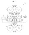
- FIG. 1illustrates a system 10 used in removing asperities from a magnetic disk 11 .
- the system 10includes a pair of mechanisms for polishing both sides of a magnetic disk 11 .
- Each of the mechanismsincludes a reel 30 , guide rollers 31 , a tensioning mechanism 32 , guide rollers 34 , a pressure mechanism including an elastic polishing pad 37 , and a take-up roller 36 .
- the reel 30feeds a polishing tape 50 wound around the reel.
- the guide rollers 31guide the polishing tape 50 fed from the reel 30 .
- the tensioning mechanism 32uses an air cylinder to apply tension to the polishing tape 50 fed between the guide rollers 31 and a guide roller 33 .
- the guide rollers 34guide the polishing tape 50 , to which the tension is applied, onto a surface of the magnetic disk 11 .
- the pressure mechanism including the polishing pad 37lets the polishing tape 50 slide over the surface of the magnetic disk 11 with a predetermined pressure by pressing the polishing tape 50 onto the surface of the magnetic disk 11 using the polishing pad 37 .
- the take-up roller 36takes up the polishing tape 50 that has undergone the polishing process via guide rollers 35 .
- the system 10applies pressure to the polishing tapes 50 such that the tapes 50 are brought into contact with the corresponding surfaces of the magnetic disk 11 , which is kept rotating.
- the system 10thus removes asperities from both sides of the magnetic disk 11 at the same time. For example, when the polishing tape 50 contacts the magnetic disk 11 and the desired pressure is reached, the polishing tape 50 is moved radially from an inner periphery to an outer periphery of the magnetic disk 11 . Thus, the entire recording surfaces of the magnetic disk 11 are polished.
- the contact pressure of the polishing tape 50 on the magnetic disk 11 surfaceis controlled by the pressure mechanism that presses the polishing pad 37 against the disk surface at the desired pressure.
- a base portion, on which the polishing pad 37 is mounted,serves as a strain gage sensor 38 .
- the pressure controlis a feedback system. For example, when the polishing pad 37 contacts the magnetic disk 11 via the polishing tape 50 , a stress strain is produced in the strain gage sensor 38 . A strain output caused by the stress strain is given as a voltage signal to an amplifier 41 . The voltage signal is then converted to a corresponding pressure value. A command is then issued to a servomotor so as to maintain the desired pressure. The servomotor may then drive a pressure base portion 40 by way of a ball screw.
- the strain gage sensor 38is mounted on a slide mechanism 39 with a low coefficient of friction.
- the polishing tape 50is fed a distance equivalent to or more than the length of the pad in a longitudinal direction of the tape for each disk.
- FIG. 2is a block diagram of a polishing system 100 in one exemplary embodiment of the invention.
- the polishing system 100is used to polish a magnetic disk 106 used in a disk drive.
- the polishing system 100is used to burnish relatively small asperities on a surface of the magnetic disk 106 .
- the polishing system 100may be used to remove asperities above about 5 nm.
- the polishing system 100may apply a polishing film 101 against a surface of the magnetic disk 106 .
- This polishing film 101may exist in the form of a biaxially-oriented polyethylene terephthalate polishing tape, such as Mylar.
- the polishing film 101includes a mild abrasive that is used to remove these asperities by carefully moving the film across the surface of the magnetic disk 106 .
- the polishing system 101may be configured with a mechanism that actuates motion of the tape along the surface of the magnetic disk 106 .
- the polishing system 102may include rollers 102 and 104 mechanically coupled to an actuator 107 that pulls the polishing film 101 across the rollers 102 and 104 .
- the magnetic disk 106is positioned proximate to the rollers 102 and 104 such that the polishing film 101 may be applied to the magnetic disk 106 .
- the polishing film 101is applied to the magnetic disk 106 by way of a polishing pad 103 that presses the polishing film 101 against the surface of the magnetic disk 106 .
- the polishing pad 103may apply a certain amount of pressure against the back of the polishing film 101 that forces the polishing film 101 against the surface of the magnetic disk 106 .
- the polishing film 101is then moved via the actuator 107 along the rollers 102 against the magnetic disk 106 .
- the combination of the pressure from the polishing pad 103 and the abrasive material of the polishing film 101serves to polish the asperities from the surface of the magnetic disk 106 .
- the polishing processis delicate.
- a foam pad with a higher lost tangentwas used to polish magnetic disks in the past.
- the pressure that is applied by the pad 103is substantial enough to reduce the asperities in the magnetic disk 106 yet gentle enough to prevent scratching of the surface of the magnetic disk 106 .
- Previous techniquesincluded the use of a smooth thermoplastic elastomer pad that was pressed against the back of the polishing film 101 .
- the smooth padwas effective at removing the asperities.
- the smooth padwould adhere to the back of the polishing film 101 at the end of the polishing process when the pad was retracted from the polishing film.
- This adhesion of the pad 103 to the polishing film 101could be as high as 5 g and tended to pull the polishing film 101 away from the surface of the magnetic disk 106 causing the polishing film 101 to snap back when the tension in the film became larger than the adhesion force between the polishing film and the pad. In some cases, this tape deflection could be as high as 650 ⁇ m. Again, this “snapping back” of the polishing film 101 released abrasive particles from the polishing film as well as burnished particles from the magnetic disk 106 . These loose particles can damage the surface of the magnetic disk 106 . For example, when polishing a magnetic disk for use in a disk drive, the magnetic disk is polished in a clean room environment so as to prevent loose particles from scratching the processed disk. A scratched disk may interfere with a read/write head making the disk inoperable.
- the polishing system 100overcomes the previous deficiencies by providing a pad 103 that includes one or more protrusions 105 extending from a surface 108 of the pad 103 . These protrusions 105 reduce the adhesion force between the pad 103 and the polishing film 101 . In one embodiment, the pad 103 reduces the adhesion force to below about 20 mg causing a taped deflection of only about 50 ⁇ m, thereby reducing the tape deflection by as much as 600 ⁇ m.
- the pad and the protrusions 105 thereofmay be configured from a relatively soft elastomeric polymer having a Shore A hardness in a range of about 1 to 10.
- the pad 103may be an injected molded TPE such as Kraton, Dynaflex, and Versaflex produced by GLS Corporation of McHenry, Ill. Such a material may provide a certain level of compression that is used to assist in the release of the protrusion from the polishing film 101 as illustrated in FIGS. 3A and 3B .
- FIGS. 3A and 3Billustrate a side view of a polishing pad 200 that may be used in the polishing system 100 in one exemplary embodiment of the invention.
- the pad 200is illustrated in released and compressed states in FIGS. 3A and 3B , respectively.
- the released stateshows multiple protrusions 201 extending from a surface 203 of the pad 200 .
- the springs 202 within the pad 200are merely intended to illustrate a certain level of resilience that the protrusions 201 may have.
- the pad 200may be configured from material having a certain level of elasticity that allows for the protrusions 201 to be compressed, as shown with the springs 202 in FIG. 3B , when the pad 200 is pressed against the back of the polishing film 101 during polishing.
- the protrusions 201retain their original shapes and again extend from the surface 203 of the pad 200 .
- protrusions 201reduce the adhesion force between the pad 200 and polishing film 101 .
- an adhesion forcegenerally arises from dispersive adhesion stress, or force per unit area, between the pad 200 and the polishing film 101 .
- the total adhesion forcemay be decreased if the surface area of the pad 200 in contact with the polishing film 101 is decreased when the pad 200 is retracted from the film 101 .
- the pad 200applies a relatively uniform pressure against the film 101 to maintain an even polishing of the magnetic disk 106 and, in this regard, “track” the “waviness” of the magnetic disk 106 .
- the magnetic disk 106is typically not perfectly smooth upon fabrication.
- the surface topography of the pad 200therefore, should not be dramatically altered so as to maintain intimate contact with the magnetic disk 106 during polishing.
- the pad 200configured from one or more of the materials above, compensates for this waviness of the magnetic disk 106 by remaining in intimate contact with the magnetic disk (i.e. via the polishing film 101 ) to ensure that the magnetic disk 106 is well polished.
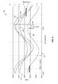
- FIG. 4is a graph 300 illustrating the tracking of various polishing pads on an uneven surface of a magnetic disk.
- the graph 300is illustrated with time on the axis 301 and strain on the axis 302 .
- a traditional polishing pad configured of foam rubberis illustrated via the plot 303 .
- a soft pad in one exemplary embodiment of the inventionis illustrated via the plot 305 and another “blended” soft pad in one exemplary embodiment of the invention is illustrated via the plot 304 .
- the soft padis injection molded from Dynaflex G6703 and the blended soft pad is injection molded from Dynaflex G6703 with 50% Dynaflex G6713. Both contain about 0.2% Armoslip E slip agent, produced by AKZO Nobel Polymer Chemicals, LLC of Chicago, Ill.
- Both the soft pad and the blended soft padare more capable of tracking the waviness of the magnetic disk 106 because these pads have a lower loss tangent as demonstrated under an oscillatory compression against the magnetic disk 106 .
- the traditional foam rubber pad of the plot 303experiences a higher loss tangent which results in a phase shift 307 , implying that the traditional foam rubber pad is less apt to track the waviness of the magnetic disk 106 .
- the relatively soft material of the pad 200allows the pad to make a more intimate contact, the protrusions 201 assist in overcoming the adhesion force by “springing out” to release the adhesion force on the regions of the surface 203 between the protrusions 201 .
- the protrusions 201may be configured of a height y with an effective spring length l.
- the compressive strain i-s then y/l and the spring recovery stressis therefore (y/l)E, where E is Young's modulus of the pad material, for example 23 kPa.
- the adhesion stress of the surface 203 of the pad 200 surrounding the protrusions 201is ⁇ , which is about 2.4 kPa measured on a smooth pad surface.
- the equation for the protrusions 201 to release the surrounding flat area from the polishing film 101is (y/l)E>(1 ⁇ f) ⁇ , where f is the surface area fraction formed by the protrusions.
- the adhesion force for protrusions 201 configured in square shapes of about 100 ⁇ m by 100 ⁇ m and spaced about 50 ⁇ m apartwas empirically determined to be about 500 mg as shown in FIG. 5 . Based on this determination, the effective spring length l is about 860 ⁇ m, meaning that the protrusion height should be at least 100 ⁇ m, preferably greater.
- the adhesion forcebelow about 400 mg. This may be achieved by decreasing the surface area on top of the protrusions 201 and configuring the protrusions farther apart, keeping in mind that the protrusion height y should be greater than l(1 ⁇ f) ⁇ /E.
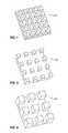
- Various pad configurations 500 - 800 of suchare shown in FIGS. 6-9 .
- the pad 500is illustrated with square surface protrusions 201 having a spacing 502 .
- the remaining pad configurations 600 to 800illustrate other various heights, spacings, and surface areas for the protrusions 201 .
- the protrusion height ymay be about 100 ⁇ m.
- FIG. 10is a graph 900 illustrating actual experimental results for adhesion force of a polishing pad (e.g., the pad 200 ) with respect to the fractional surface area of the protrusions (e.g., the protrusions 201 ) in one exemplary embodiment of the invention.
- various pad configurationswere implemented, each of which being Dynaflex G6703 injection molded with about 0.2% Armoslip E.
- the graph 900shows that the adhesion force scales almost linearly along line 903 according to the fractional surface area of the protrusions.
- a smooth pad configured without protrusionsyielded an adhesion force of roughly 2.8 g, causing a tape deflection of about 650 ⁇ m.
- the adhesion forcedrops significantly as illustrated in the table below:
- Point 906100 50 100 44% 1.2 320 Point 904 100 100 100 25% 0.018 50 Point 906 100 200 100 11% 0.67 180 Point 905 200 200 25% 0.017 50 Point 906
- the inventionis not intended to be so limited. Rather, other surface area shapes, such as rectangles, triangles, and circles, may be implemented for the protrusions.
- a reduced surface area fraction for the protrusionsgenerally reduces the adhesion force. Accordingly, pyramidal and conical shapes extending from the surface of the pad may improve the adhesion force reduction.
- a “rounding” of the square profile design of the protrusionsmay occur during the injection molding process. The rounding deformation is probably caused by partial recovery of a polymer chain deformation that is “frozen-in” when the molten polymer cools while flowing into the protrusion cavities of a mold.
- FIGS. 11-15illustrate mounts used to retain various polishing pads in exemplary embodiments of the invention.
- the polishing padsmay take a variety of shapes that relieve the adhesion force when configured with a TPE.
- the padis configured within a mount that rigidly retains the pad.
- TPEhas been difficult to secure making a TPE pad apply nonuniform pressure during the polishing process.
- the mounts and the TPE pads hereinalleviate such difficulties making the TPE pad a better polishing pad than the traditional foam rubber polishing pads.
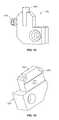
- FIGS. 11 and 12a cylindrical TPE pad 1002 is retained within the mount 1000 .
- FIG. 11illustrates the TPE pad 1002 residing within a similarly shaped retaining section within the mount 1000 .
- the TPE pad 1002may be retained within the mount 1000 using an adhesive, but the adhesive bond to such materials may be unreliable. However, it is the rigid support of the mount 1000 that ensures that the TPE pad 1002 applies a uniform pressure when secured to an actuator via the coupling mechanism 1003 .
- FIG. 12illustrates a similar embodiment where the TPE pad 1002 is instead retained with a locking bolt 1105 . Compressing a pad cylinder with a locking bolt may cause an unacceptable variation in the pad height.
- FIGS. 11illustrates the TPE pad 1002 residing within a similarly shaped retaining section within the mount 1000 .
- the TPE pad 1002may be retained within the mount 1000 using an adhesive, but the adhesive bond to such materials may be unreliable. However, it is the rigid support of the mount 1000 that ensures
- FIGS. 13 through 15illustrate rectangular shaped pads 1202 and 1302 and their respective mechanisms for retaining the pads.
- the rectangular pad 1202is configured with tabs 1203 that are retained within a similarly shaped section of the mount 1201 .
- FIGS. 14 and 15illustrate another embodiment where the rectangular pad 1302 is configured with a tab 1310 that resides within the mount 1301 .
- a “door” 1305allows for the pad 1302 to slide into a cavity in the mount 1301 . The door 1305 then closes and provides a rigid support for the pad 1302 to ensure that the pad applies a uniform pressure against the back of the polishing film 101 and remains precisely located within the cavity of the holder.
- FIG. 16is a flowchart of a process 1500 for polishing a magnetic disk 106 in one exemplary embodiment of the invention.
- the process 1500may be implemented so as to burnish a magnetic disk used in a disk drive system such that the storage capacity of the disk drive system may be increased.
- the process 1500initiates when the magnetic disk 106 is retained within a mount in the process element 1501 .
- the polishing system 100then positions the polishing pad 103 proximate to the magnetic disk 106 in the process element 1502 .
- the polishing system 100then applies a polishing film 101 to the magnetic disk 106 via the polishing pad 103 in the process element 1503 .
- the polishing system 100may apply pressure to the back of the polishing film 101 via the polishing pad 103 such that the polishing film 101 makes intimate contact with the magnetic disk 106 .
- the polishing pad 103includes one or more protrusions that are designed to compress to about the surface of the polishing pad as shown and described in FIGS. 2A and 2B .
- the polishing film 101may be configured as a Mylar tape having an abrasive material that is used to polish the magnetic disk 106 when the film is applied to the magnetic disk 106 via the polishing pad 103 and moved about.
- the actuator 107in this regard, moves the polishing film 101 about the surface of the magnetic disk 106 in the process element 1504 .
- the polishing processconcludes after a certain number of passes required to remove the asperities from the magnetic disk 106 (e.g., process element 1505 ).
- the polishing system 100retracts the polishing pad 103 from the polishing film 101 in the process element 1506 .
- the protrusions extending from the polishing pad 103reduce a surface area adhesion between the pad 103 and the polishing film 101 .
- the protrusionstend to spring out from a surface of the pad 103 and essentially break the adhesion force between the polishing film 101 and the pad 103 .
- the protrusionsmay be configured in a variety of shapes and spacings to reduce the adhesion force and thus the deflection of the polishing film 101 . This reduced deflection assists in preventing dispersion of particles that may potentially damage the magnetic disk 106 .
Landscapes
- Engineering & Computer Science (AREA)
- Mechanical Engineering (AREA)
- Finish Polishing, Edge Sharpening, And Grinding By Specific Grinding Devices (AREA)
- Manufacturing Of Magnetic Record Carriers (AREA)
Abstract
Description
| Surface | Measured | Tape | ||||
| Width, | Spac- | Height, | Area | Adhesion | Deflec- | Location |
| x, | ing, w, | y, | Fraction, | Force in | tion | on Graph |
| in μm | in μm | in μm | f | grams | in | 900 |
| 0 | 0 | 0 | 100% | 2.8 | 650 | |
| 100 | 50 | 100 | 44% | 1.2 | 320 | |
| 100 | 100 | 100 | 25% | 0.018 | 50 | |
| 100 | 200 | 100 | 11% | 0.67 | 180 | |
| 200 | 200 | 200 | 25% | 0.017 | 50 | |
Claims (15)
Priority Applications (1)
| Application Number | Priority Date | Filing Date | Title |
|---|---|---|---|
| US12/403,273US8192249B2 (en) | 2009-03-12 | 2009-03-12 | Systems and methods for polishing a magnetic disk |
Applications Claiming Priority (1)
| Application Number | Priority Date | Filing Date | Title |
|---|---|---|---|
| US12/403,273US8192249B2 (en) | 2009-03-12 | 2009-03-12 | Systems and methods for polishing a magnetic disk |
Publications (2)
| Publication Number | Publication Date |
|---|---|
| US20100233940A1 US20100233940A1 (en) | 2010-09-16 |
| US8192249B2true US8192249B2 (en) | 2012-06-05 |
Family
ID=42731102
Family Applications (1)
| Application Number | Title | Priority Date | Filing Date |
|---|---|---|---|
| US12/403,273Expired - Fee RelatedUS8192249B2 (en) | 2009-03-12 | 2009-03-12 | Systems and methods for polishing a magnetic disk |
Country Status (1)
| Country | Link |
|---|---|
| US (1) | US8192249B2 (en) |
Cited By (1)
| Publication number | Priority date | Publication date | Assignee | Title |
|---|---|---|---|---|
| US20140287659A1 (en)* | 2013-03-19 | 2014-09-25 | Panasonic Corporation | Machining method and machining device of component |
Families Citing this family (2)
| Publication number | Priority date | Publication date | Assignee | Title |
|---|---|---|---|---|
| JP5886602B2 (en)* | 2011-03-25 | 2016-03-16 | 株式会社荏原製作所 | Polishing apparatus and polishing method |
| JP6004992B2 (en)* | 2013-06-10 | 2016-10-12 | ワイエイシイ株式会社 | Substrate surface processing equipment |
Citations (40)
| Publication number | Priority date | Publication date | Assignee | Title |
|---|---|---|---|---|
| US3787273A (en)* | 1971-06-07 | 1974-01-22 | Norton Co | Low stretch sectional abrasive belts |
| US4412400A (en)* | 1980-10-20 | 1983-11-01 | Verbatim Corporation | Apparatus for burnishing |
| US4656790A (en)* | 1984-12-04 | 1987-04-14 | Fuji Photo Film Co., Ltd. | Burnishing method and apparatus for magnetic disk |
| US4930259A (en)* | 1988-02-19 | 1990-06-05 | Magnetic Perpherals Inc. | Magnetic disk substrate polishing assembly |
| US5209027A (en)* | 1989-10-13 | 1993-05-11 | Tdk Corporation | Polishing of the rear surface of a stamper for optical disk reproduction |
| US5643044A (en)* | 1994-11-01 | 1997-07-01 | Lund; Douglas E. | Automatic chemical and mechanical polishing system for semiconductor wafers |
| US5733181A (en)* | 1993-10-29 | 1998-03-31 | Shin-Etsu Handotai Co., Ltd. | Apparatus for polishing the notch of a wafer |
| US6036579A (en) | 1997-01-13 | 2000-03-14 | Rodel Inc. | Polymeric polishing pad having photolithographically induced surface patterns(s) and methods relating thereto |
| US6074284A (en)* | 1997-08-25 | 2000-06-13 | Unique Technology International Pte. Ltd. | Combination electrolytic polishing and abrasive super-finishing method |
| US6086986A (en)* | 1996-03-21 | 2000-07-11 | Fuji Photo Film Co., Ltd. | Cleaning medium for magnetic recording devices |
| JP2000263423A (en) | 1999-03-16 | 2000-09-26 | Toray Ind Inc | Polishing pad and polishing device |
| US6155914A (en)* | 1997-09-22 | 2000-12-05 | Seagate Technologies, Llc | Apparatus for the application of an advanced texture process |
| JP2001047355A (en) | 1999-08-06 | 2001-02-20 | Jsr Corp | Polymer composition for polishing pad and polishing pad using the same |
| US6193590B1 (en)* | 1995-06-23 | 2001-02-27 | Akashic Memories Corp. | Abrasive tape for texturing magnetic recording media |
| JP2001067655A (en) | 1999-06-22 | 2001-03-16 | Mitsubishi Chemicals Corp | Manufacturing method of information recording medium |
| JP2001261874A (en) | 2000-01-12 | 2001-09-26 | Toyo Tire & Rubber Co Ltd | Thermoplastic elastomer microporous foam, method for producing the same, and polishing sheet |
| US6332832B1 (en)* | 1999-04-19 | 2001-12-25 | Rohm Company, Ltd. | CMP polish pad and CMP processing apparatus using the same |
| JP2002124491A (en) | 2000-08-10 | 2002-04-26 | Toray Ind Inc | Polishing pad |
| US6402596B1 (en)* | 2000-01-25 | 2002-06-11 | Speedfam-Ipec Co., Ltd. | Single-side polishing method for substrate edge, and apparatus therefor |
| JP2002178255A (en) | 2000-12-14 | 2002-06-25 | Toray Ind Inc | Polishing pad |
| US20020187732A1 (en)* | 1999-09-01 | 2002-12-12 | Moore Scott E. | Method and apparatus for planarizing a microelectronic substrate with a tilted planarizing surface |
| US6592435B2 (en)* | 2000-07-17 | 2003-07-15 | Sony Corporation | Method of and apparatus for manufacturing recording medium |
| US6648733B2 (en)* | 1997-04-04 | 2003-11-18 | Rodel Holdings, Inc. | Polishing pads and methods relating thereto |
| US6705927B2 (en)* | 1997-11-17 | 2004-03-16 | Nihon Microcoating Co., Ltd. | Method of producing magnetic hard disk substrate with textured surface |
| US6761620B2 (en)* | 2002-09-13 | 2004-07-13 | Infineon Technologies Ag | Finishing pad design for multidirectional use |
| US6777498B2 (en)* | 2001-08-31 | 2004-08-17 | Mitsui Chemicals, Inc. | Olefin thermoplastic elastomer, process for producing the same and use thereof |
| US6848974B2 (en) | 2001-09-25 | 2005-02-01 | Jsr Corporation | Polishing pad for semiconductor wafer and polishing process using thereof |
| US20050032468A1 (en)* | 2002-10-01 | 2005-02-10 | 3M Innovative Properties Company | Apparatus and method for forming a spiral wound abrasive article, and the resulting article |
| US6884156B2 (en) | 2003-06-17 | 2005-04-26 | Cabot Microelectronics Corporation | Multi-layer polishing pad material for CMP |
| US6893329B2 (en)* | 2003-03-17 | 2005-05-17 | Hitachi High-Tech Electronics Engineering Co., Ltd. | Polishing apparatus with abrasive tape, polishing method using abrasive tape and manufacturing method for magnetic disk |
| US6913517B2 (en) | 2002-05-23 | 2005-07-05 | Cabot Microelectronics Corporation | Microporous polishing pads |
| US20050197050A1 (en) | 2003-06-17 | 2005-09-08 | Cabot Microelectronics Corporation | Multi-layer polishing pad material for CMP |
| US6964604B2 (en)* | 2000-06-23 | 2005-11-15 | International Business Machines Corporation | Fiber embedded polishing pad |
| US20050287932A1 (en)* | 2004-06-25 | 2005-12-29 | Basol Bulent M | Article for polishin substrate surface |
| US20060088735A1 (en) | 2004-10-27 | 2006-04-27 | Hitachi Global Storage Technologies Netherlands B.V. | Method for manufacturing magnetic disk using cleaning tape |
| JP2006142439A (en) | 2004-11-22 | 2006-06-08 | Sumitomo Bakelite Co Ltd | Polishing pad and polishing method using the same |
| JP2006142440A (en) | 2004-11-22 | 2006-06-08 | Sumitomo Bakelite Co Ltd | Polishing pad and polishing method using the same |
| JP2006339570A (en) | 2005-06-06 | 2006-12-14 | Toray Ind Inc | Polishing pad and polishing apparatus |
| JP2007326984A (en) | 2006-06-09 | 2007-12-20 | Kuraray Co Ltd | Polymer material, foam obtained therefrom, and polishing pad using the same |
| EP1927605A1 (en) | 2005-09-22 | 2008-06-04 | Kuraray Co., Ltd. | Polymer material, foam obtained from same, and polishing pad using those |
- 2009
- 2009-03-12USUS12/403,273patent/US8192249B2/ennot_activeExpired - Fee Related
Patent Citations (41)
| Publication number | Priority date | Publication date | Assignee | Title |
|---|---|---|---|---|
| US3787273A (en)* | 1971-06-07 | 1974-01-22 | Norton Co | Low stretch sectional abrasive belts |
| US4412400A (en)* | 1980-10-20 | 1983-11-01 | Verbatim Corporation | Apparatus for burnishing |
| US4656790A (en)* | 1984-12-04 | 1987-04-14 | Fuji Photo Film Co., Ltd. | Burnishing method and apparatus for magnetic disk |
| US4656790B1 (en)* | 1984-12-04 | 1989-01-10 | ||
| US4930259A (en)* | 1988-02-19 | 1990-06-05 | Magnetic Perpherals Inc. | Magnetic disk substrate polishing assembly |
| US5209027A (en)* | 1989-10-13 | 1993-05-11 | Tdk Corporation | Polishing of the rear surface of a stamper for optical disk reproduction |
| US5733181A (en)* | 1993-10-29 | 1998-03-31 | Shin-Etsu Handotai Co., Ltd. | Apparatus for polishing the notch of a wafer |
| US5643044A (en)* | 1994-11-01 | 1997-07-01 | Lund; Douglas E. | Automatic chemical and mechanical polishing system for semiconductor wafers |
| US6193590B1 (en)* | 1995-06-23 | 2001-02-27 | Akashic Memories Corp. | Abrasive tape for texturing magnetic recording media |
| US6086986A (en)* | 1996-03-21 | 2000-07-11 | Fuji Photo Film Co., Ltd. | Cleaning medium for magnetic recording devices |
| US6036579A (en) | 1997-01-13 | 2000-03-14 | Rodel Inc. | Polymeric polishing pad having photolithographically induced surface patterns(s) and methods relating thereto |
| US6648733B2 (en)* | 1997-04-04 | 2003-11-18 | Rodel Holdings, Inc. | Polishing pads and methods relating thereto |
| US6074284A (en)* | 1997-08-25 | 2000-06-13 | Unique Technology International Pte. Ltd. | Combination electrolytic polishing and abrasive super-finishing method |
| US6155914A (en)* | 1997-09-22 | 2000-12-05 | Seagate Technologies, Llc | Apparatus for the application of an advanced texture process |
| US6705927B2 (en)* | 1997-11-17 | 2004-03-16 | Nihon Microcoating Co., Ltd. | Method of producing magnetic hard disk substrate with textured surface |
| JP2000263423A (en) | 1999-03-16 | 2000-09-26 | Toray Ind Inc | Polishing pad and polishing device |
| US6332832B1 (en)* | 1999-04-19 | 2001-12-25 | Rohm Company, Ltd. | CMP polish pad and CMP processing apparatus using the same |
| JP2001067655A (en) | 1999-06-22 | 2001-03-16 | Mitsubishi Chemicals Corp | Manufacturing method of information recording medium |
| JP2001047355A (en) | 1999-08-06 | 2001-02-20 | Jsr Corp | Polymer composition for polishing pad and polishing pad using the same |
| US20020187732A1 (en)* | 1999-09-01 | 2002-12-12 | Moore Scott E. | Method and apparatus for planarizing a microelectronic substrate with a tilted planarizing surface |
| JP2001261874A (en) | 2000-01-12 | 2001-09-26 | Toyo Tire & Rubber Co Ltd | Thermoplastic elastomer microporous foam, method for producing the same, and polishing sheet |
| US6402596B1 (en)* | 2000-01-25 | 2002-06-11 | Speedfam-Ipec Co., Ltd. | Single-side polishing method for substrate edge, and apparatus therefor |
| US6964604B2 (en)* | 2000-06-23 | 2005-11-15 | International Business Machines Corporation | Fiber embedded polishing pad |
| US6592435B2 (en)* | 2000-07-17 | 2003-07-15 | Sony Corporation | Method of and apparatus for manufacturing recording medium |
| JP2002124491A (en) | 2000-08-10 | 2002-04-26 | Toray Ind Inc | Polishing pad |
| JP2002178255A (en) | 2000-12-14 | 2002-06-25 | Toray Ind Inc | Polishing pad |
| US6777498B2 (en)* | 2001-08-31 | 2004-08-17 | Mitsui Chemicals, Inc. | Olefin thermoplastic elastomer, process for producing the same and use thereof |
| US6848974B2 (en) | 2001-09-25 | 2005-02-01 | Jsr Corporation | Polishing pad for semiconductor wafer and polishing process using thereof |
| US6913517B2 (en) | 2002-05-23 | 2005-07-05 | Cabot Microelectronics Corporation | Microporous polishing pads |
| US6761620B2 (en)* | 2002-09-13 | 2004-07-13 | Infineon Technologies Ag | Finishing pad design for multidirectional use |
| US20050032468A1 (en)* | 2002-10-01 | 2005-02-10 | 3M Innovative Properties Company | Apparatus and method for forming a spiral wound abrasive article, and the resulting article |
| US6893329B2 (en)* | 2003-03-17 | 2005-05-17 | Hitachi High-Tech Electronics Engineering Co., Ltd. | Polishing apparatus with abrasive tape, polishing method using abrasive tape and manufacturing method for magnetic disk |
| US20050197050A1 (en) | 2003-06-17 | 2005-09-08 | Cabot Microelectronics Corporation | Multi-layer polishing pad material for CMP |
| US6884156B2 (en) | 2003-06-17 | 2005-04-26 | Cabot Microelectronics Corporation | Multi-layer polishing pad material for CMP |
| US20050287932A1 (en)* | 2004-06-25 | 2005-12-29 | Basol Bulent M | Article for polishin substrate surface |
| US20060088735A1 (en) | 2004-10-27 | 2006-04-27 | Hitachi Global Storage Technologies Netherlands B.V. | Method for manufacturing magnetic disk using cleaning tape |
| JP2006142439A (en) | 2004-11-22 | 2006-06-08 | Sumitomo Bakelite Co Ltd | Polishing pad and polishing method using the same |
| JP2006142440A (en) | 2004-11-22 | 2006-06-08 | Sumitomo Bakelite Co Ltd | Polishing pad and polishing method using the same |
| JP2006339570A (en) | 2005-06-06 | 2006-12-14 | Toray Ind Inc | Polishing pad and polishing apparatus |
| EP1927605A1 (en) | 2005-09-22 | 2008-06-04 | Kuraray Co., Ltd. | Polymer material, foam obtained from same, and polishing pad using those |
| JP2007326984A (en) | 2006-06-09 | 2007-12-20 | Kuraray Co Ltd | Polymer material, foam obtained therefrom, and polishing pad using the same |
Cited By (2)
| Publication number | Priority date | Publication date | Assignee | Title |
|---|---|---|---|---|
| US20140287659A1 (en)* | 2013-03-19 | 2014-09-25 | Panasonic Corporation | Machining method and machining device of component |
| US9144877B2 (en)* | 2013-03-19 | 2015-09-29 | Panasonic Intellectual Property Management Co., Ltd. | Machining method and machining device of component |
Also Published As
| Publication number | Publication date |
|---|---|
| US20100233940A1 (en) | 2010-09-16 |
Similar Documents
| Publication | Publication Date | Title |
|---|---|---|
| US8797677B2 (en) | Disk deflection damper for disk drive | |
| US8553356B1 (en) | Disk limiter for disk drive | |
| US8192249B2 (en) | Systems and methods for polishing a magnetic disk | |
| WO2009142295A1 (en) | Laminated body for manufacturing resin mold, laminated body, resin mold and method for manufacturing magnetic recording medium | |
| JPH0640382B2 (en) | Magnetic recording medium | |
| KR20010052381A (en) | Apparatus for differential zone lubrication of magnetic recording media and related methods | |
| US9296082B1 (en) | Disk buffing apparatus with abrasive tape loading pad having a vibration absorbing layer | |
| JP5325458B2 (en) | Method for manufacturing magnetic recording medium | |
| EP2105920A1 (en) | Imprint mold structure and imprint method using the same, and method for manufacturing magnetic recording medium | |
| JP2010188701A (en) | Mold for molding resin stamper and method for producing resin stamper using the mold | |
| JP2002056530A (en) | Magnetic transferring method | |
| US7398940B2 (en) | Leader tape, method for manufacturing the same, and magnetic tape cartridge | |
| EP0531162B1 (en) | Magnetic head device with cleaning means for cleaning sliding surface thereof | |
| US7983007B2 (en) | Magnetic tape apparatus | |
| US11152022B2 (en) | Warp correction apparatus for plate-like workpiece and warp correction method | |
| US20100086676A1 (en) | Apparatus for Cleaning Magnetic Disks and Methods for Manufacturing Magnetic Disks | |
| US8296931B2 (en) | Method for manufacturing storage medium | |
| JP4101595B2 (en) | Manufacturing method of anti-slip sheet for turntable | |
| JPS63156650A (en) | Disc finishing equipment | |
| US20060216550A1 (en) | Method of manufacturing master disk for magnetic transfer, master disk for magnetic transfer, and magnetic recording medium | |
| JPS5840256B2 (en) | film film | |
| JP5654247B2 (en) | Guide member, magnetic tape drive, magnetic tape | |
| JP2605846B2 (en) | Polishing method for magnetic recording media | |
| JPH08111014A (en) | Method for grinding sliding surface of magnetic head slider | |
| JPS59110546A (en) | Polishing head |
Legal Events
| Date | Code | Title | Description |
|---|---|---|---|
| AS | Assignment | Owner name:HITACHI GLOBAL STORAGE TECHNOLOGIES NETHERLANDS B. Free format text:ASSIGNMENT OF ASSIGNORS INTEREST;ASSIGNORS:CARTER, MALIKA D.;HSIAO, YUN-LIN;KARIS, THOMAS E.;AND OTHERS;SIGNING DATES FROM 20090219 TO 20090312;REEL/FRAME:022391/0171 | |
| FEPP | Fee payment procedure | Free format text:PAYOR NUMBER ASSIGNED (ORIGINAL EVENT CODE: ASPN); ENTITY STATUS OF PATENT OWNER: LARGE ENTITY | |
| STCF | Information on status: patent grant | Free format text:PATENTED CASE | |
| AS | Assignment | Owner name:HGST, NETHERLANDS B.V., NETHERLANDS Free format text:CHANGE OF NAME;ASSIGNOR:HGST, NETHERLANDS B.V.;REEL/FRAME:029341/0777 Effective date:20120723 Owner name:HGST NETHERLANDS B.V., NETHERLANDS Free format text:CHANGE OF NAME;ASSIGNOR:HITACHI GLOBAL STORAGE TECHNOLOGIES NETHERLANDS B.V.;REEL/FRAME:029341/0777 Effective date:20120723 | |
| CC | Certificate of correction | ||
| FPAY | Fee payment | Year of fee payment:4 | |
| AS | Assignment | Owner name:WESTERN DIGITAL TECHNOLOGIES, INC., CALIFORNIA Free format text:ASSIGNMENT OF ASSIGNORS INTEREST;ASSIGNOR:HGST NETHERLANDS B.V.;REEL/FRAME:040826/0821 Effective date:20160831 | |
| FEPP | Fee payment procedure | Free format text:MAINTENANCE FEE REMINDER MAILED (ORIGINAL EVENT CODE: REM.); ENTITY STATUS OF PATENT OWNER: LARGE ENTITY | |
| LAPS | Lapse for failure to pay maintenance fees | Free format text:PATENT EXPIRED FOR FAILURE TO PAY MAINTENANCE FEES (ORIGINAL EVENT CODE: EXP.); ENTITY STATUS OF PATENT OWNER: LARGE ENTITY | |
| STCH | Information on status: patent discontinuation | Free format text:PATENT EXPIRED DUE TO NONPAYMENT OF MAINTENANCE FEES UNDER 37 CFR 1.362 | |
| FP | Lapsed due to failure to pay maintenance fee | Effective date:20200605 |