US8191421B2 - Digital ballistic impact detection system - Google Patents
Digital ballistic impact detection systemDownload PDFInfo
- Publication number
- US8191421B2 US8191421B2US12/266,144US26614408AUS8191421B2US 8191421 B2US8191421 B2US 8191421B2US 26614408 AUS26614408 AUS 26614408AUS 8191421 B2US8191421 B2US 8191421B2
- Authority
- US
- United States
- Prior art keywords
- impact
- recorder
- ballistic
- providing
- ballistic impact
- Prior art date
- Legal status (The legal status is an assumption and is not a legal conclusion. Google has not performed a legal analysis and makes no representation as to the accuracy of the status listed.)
- Expired - Fee Related, expires
Links
- 238000001514detection methodMethods0.000titledescription15
- 238000000034methodMethods0.000claimsabstractdescription32
- 239000002360explosiveSubstances0.000claimsabstract3
- 230000035939shockEffects0.000claimsdescription68
- 230000004044responseEffects0.000claimsdescription19
- 230000006378damageEffects0.000claimsdescription16
- 208000027418Wounds and injuryDiseases0.000claimsdescription15
- 208000014674injuryDiseases0.000claimsdescription13
- 239000010409thin filmSubstances0.000claimsdescription6
- 238000005259measurementMethods0.000claimsdescription5
- 230000015556catabolic processEffects0.000claimsdescription4
- 230000007958sleepEffects0.000claimsdescription4
- 238000001228spectrumMethods0.000claimsdescription4
- 230000001174ascending effectEffects0.000claimsdescription3
- 230000006266hibernationEffects0.000claims2
- 230000002000scavenging effectEffects0.000claims2
- 239000000463materialSubstances0.000abstractdescription15
- 230000003595spectral effectEffects0.000abstractdescription8
- 239000010410layerSubstances0.000description16
- 208000030886Traumatic Brain injuryDiseases0.000description6
- 238000005452bendingMethods0.000description6
- 230000008901benefitEffects0.000description6
- 230000006870functionEffects0.000description6
- 230000009529traumatic brain injuryEffects0.000description6
- 238000012545processingMethods0.000description5
- 230000001960triggered effectEffects0.000description5
- 238000004458analytical methodMethods0.000description4
- 230000000694effectsEffects0.000description4
- 238000004880explosionMethods0.000description4
- XUIMIQQOPSSXEZ-UHFFFAOYSA-NSiliconChemical compound[Si]XUIMIQQOPSSXEZ-UHFFFAOYSA-N0.000description3
- 230000008859changeEffects0.000description3
- 238000013016dampingMethods0.000description3
- 238000003745diagnosisMethods0.000description3
- 238000011156evaluationMethods0.000description3
- 230000010354integrationEffects0.000description3
- 238000004519manufacturing processMethods0.000description3
- 238000012986modificationMethods0.000description3
- 230000004048modificationEffects0.000description3
- 230000008569processEffects0.000description3
- 229910052710siliconInorganic materials0.000description3
- 239000010703siliconSubstances0.000description3
- 239000002344surface layerSubstances0.000description3
- VYPSYNLAJGMNEJ-UHFFFAOYSA-NSilicium dioxideChemical compoundO=[Si]=OVYPSYNLAJGMNEJ-UHFFFAOYSA-N0.000description2
- 208000003443UnconsciousnessDiseases0.000description2
- 230000003111delayed effectEffects0.000description2
- 230000005284excitationEffects0.000description2
- 238000010304firingMethods0.000description2
- 230000000266injurious effectEffects0.000description2
- 230000009191jumpingEffects0.000description2
- 230000000926neurological effectEffects0.000description2
- BASFCYQUMIYNBI-UHFFFAOYSA-NplatinumChemical compound[Pt]BASFCYQUMIYNBI-UHFFFAOYSA-N0.000description2
- 206010019196Head injuryDiseases0.000description1
- 206010061245Internal injuryDiseases0.000description1
- 229910052581Si3N4Inorganic materials0.000description1
- 230000006978adaptationEffects0.000description1
- 239000000853adhesiveSubstances0.000description1
- 230000001070adhesive effectEffects0.000description1
- 230000004075alterationEffects0.000description1
- 229910002113barium titanateInorganic materials0.000description1
- 210000004556brainAnatomy0.000description1
- 238000012512characterization methodMethods0.000description1
- 238000004891communicationMethods0.000description1
- 239000002131composite materialSubstances0.000description1
- 238000002591computed tomographyMethods0.000description1
- 238000013481data captureMethods0.000description1
- 238000013480data collectionMethods0.000description1
- 230000007812deficiencyEffects0.000description1
- 238000005137deposition processMethods0.000description1
- 230000008030eliminationEffects0.000description1
- 238000003379elimination reactionMethods0.000description1
- 239000004744fabricSubstances0.000description1
- 238000001914filtrationMethods0.000description1
- 230000001788irregularEffects0.000description1
- 230000002045lasting effectEffects0.000description1
- 238000002595magnetic resonance imagingMethods0.000description1
- 230000005415magnetizationEffects0.000description1
- 229910052751metalInorganic materials0.000description1
- 239000002184metalSubstances0.000description1
- 238000012544monitoring processMethods0.000description1
- 229910052697platinumInorganic materials0.000description1
- 238000002360preparation methodMethods0.000description1
- 239000004065semiconductorSubstances0.000description1
- 230000035945sensitivityEffects0.000description1
- 235000012239silicon dioxideNutrition0.000description1
- 239000000377silicon dioxideSubstances0.000description1
- HQVNEWCFYHHQES-UHFFFAOYSA-Nsilicon nitrideChemical compoundN12[Si]34N5[Si]62N3[Si]51N64HQVNEWCFYHHQES-UHFFFAOYSA-N0.000description1
- 239000000758substrateSubstances0.000description1
- 230000008961swellingEffects0.000description1
- 238000012546transferMethods0.000description1
- 230000001052transient effectEffects0.000description1
- 230000000007visual effectEffects0.000description1
Images


Classifications
- F—MECHANICAL ENGINEERING; LIGHTING; HEATING; WEAPONS; BLASTING
- F41—WEAPONS
- F41H—ARMOUR; ARMOURED TURRETS; ARMOURED OR ARMED VEHICLES; MEANS OF ATTACK OR DEFENCE, e.g. CAMOUFLAGE, IN GENERAL
- F41H1/00—Personal protection gear
- F41H1/04—Protection helmets
- F—MECHANICAL ENGINEERING; LIGHTING; HEATING; WEAPONS; BLASTING
- F41—WEAPONS
- F41H—ARMOUR; ARMOURED TURRETS; ARMOURED OR ARMED VEHICLES; MEANS OF ATTACK OR DEFENCE, e.g. CAMOUFLAGE, IN GENERAL
- F41H1/00—Personal protection gear
- F41H1/02—Armoured or projectile- or missile-resistant garments; Composite protection fabrics
- G—PHYSICS
- G01—MEASURING; TESTING
- G01D—MEASURING NOT SPECIALLY ADAPTED FOR A SPECIFIC VARIABLE; ARRANGEMENTS FOR MEASURING TWO OR MORE VARIABLES NOT COVERED IN A SINGLE OTHER SUBCLASS; TARIFF METERING APPARATUS; MEASURING OR TESTING NOT OTHERWISE PROVIDED FOR
- G01D21/00—Measuring or testing not otherwise provided for
- G—PHYSICS
- G01—MEASURING; TESTING
- G01L—MEASURING FORCE, STRESS, TORQUE, WORK, MECHANICAL POWER, MECHANICAL EFFICIENCY, OR FLUID PRESSURE
- G01L5/00—Apparatus for, or methods of, measuring force, work, mechanical power, or torque, specially adapted for specific purposes
- G01L5/0052—Apparatus for, or methods of, measuring force, work, mechanical power, or torque, specially adapted for specific purposes measuring forces due to impact
- G—PHYSICS
- G01—MEASURING; TESTING
- G01L—MEASURING FORCE, STRESS, TORQUE, WORK, MECHANICAL POWER, MECHANICAL EFFICIENCY, OR FLUID PRESSURE
- G01L5/00—Apparatus for, or methods of, measuring force, work, mechanical power, or torque, specially adapted for specific purposes
- G01L5/14—Apparatus for, or methods of, measuring force, work, mechanical power, or torque, specially adapted for specific purposes for measuring the force of explosions; for measuring the energy of projectiles
Definitions
- the present inventioncan also comprise an impact recorder configured to measure the severity of any impact event, having at its core a self-powered shock sensor comprised of an array of piezoelectric cantilever or microcantilever beams.
- the array of piezoelectric cantilever beamscan be tuned for resonant vibration in the range of frequencies corresponding to the range of frequencies excited by the impact event, and through the resonant vibration self-generate an electric signal that is proportional to the shock value of the impact event.
- the impact recordercan also include an electronic circuit that is configured to carry the electric signal away from the shock sensor, and a latchable electronic memory constructed to capture and store the maximum value of the electric signal generated by the array of piezoelectric cantilever beams.
- FIG. 2illustrates a perspective view of self-powered shock sensor, according to an exemplary embodiment of the present invention
- FIG. 7is a flowchart depicting a method for diagnosing the severity of an injury to a combat soldier caused by a ballistic impact event, according to an exemplary embodiment of the present invention.
- FIG. 1Illustrated in FIG. 1 is a schematic drawing of an exemplary embodiment 10 of the digital ballistic impact detection system as applied in a battlefield environment.
- the systemcan be mounted on a soldier's helmet and the results can be read out using a wireless reader.
- the detection system of the present inventioncan comprise, among other things, a zero-power or ultra-low power impact recorder capable of detecting, quantifying, recording and transmitting the maximum energy of a blast or impact to the head for aiding in the triage and diagnosis of Traumatic Brain Injury (TBI) in soldiers on the battlefield.
- TBITraumatic Brain Injury
- the medic 28can used a readout device to 26 to view the maximum shock values captured by the recorder(s) 24 and assess the likelihood of TBI or other internal injuries not visible to the naked eye. With this information in hand, the medic can then perform triage and initiate an early treatment more suited to the specific injuries suffered by the soldier, and possibly prevent the onset of delayed neurological damage resulting from head trauma that could otherwise go undetected.
- an electronic timercan be included that is triggered by the ballistic impact sensor response in order to estimate: (1) the time elapsed from impact, and (2) the duration of impact.
- the array 32 of cantilever beams 36can be configured with a piezoelectric sensor 40 attached to or integrated within the top surface 38 , the bottom surface, or both the top and bottom surfaces of the beam.
- the piezoelectric sensorcan comprise a piezoelectric material sandwiched between two electrode layers, wherein the electrode layers can be platinum and the piezoelectric material can be PZT, BaTiO3, ZnO, MN or PbNiNbO, etc. Other similar or compatible materials for the electrodes and piezoelectric material can also be considered to fall within the scope of the present invention.
- a shock sensor 30comprised of an array 32 of electromechanical resonators 34 can be sensitive to a shock wave only in one direction, such as perpendicular to the plane of the array. While this limitation can require the combination of signals from multiple sensors aligned along traversing axis to accurately measure a ballistic impact event, the information provided by each sensor group necessarily includes both the magnitude and direction of the impact. In an advanced embodiment, this information can be used to provide a triangulation feature which identifies the impact location of the ballistic impact event as well as its magnitude. An algorithm that uses the location and magnitude of the ballistic impact can also be used to remotely estimate the severity of the injury.
- FIGS. 3 a and 3 bare exemplary time waveforms depicting a shock wave produced by a non-ballistic impact event 52 and a ballistic impact event 54 , after traveling through the body or head of the soldier, and as received at the location of the impact recorder of the present invention.
- Each y-axiscan identify the amplitude (A) of the shock impact with a range up to plus/minus 50 g's, and the x-axis can indicate the passage of time (t), which for a short duration impact events can be a short as 50 ms to 10 ms, or less. It can be appreciated when comparing the two time waveform plots that the ballistic impact event can have a greater overall strength and additional high frequency components than the non-ballistic impact event.
- the raw time waveformscan be analog signals provided by a vibration sensor such as an accelerometer. If the analog signals were to be digitized and processed with DSP electronics and techniques, the resulting frequency spectrum, obtained by FFT (Fast Fourier Transform) of the two impact events can be overlaid in FIG. 3 c in which the y-axis identified the amplitude (A) of the vibration and the x-axis displays the frequency (f).
- FFTFast Fourier Transform
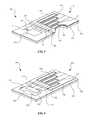
- the shock sensor 110can be comprised of an array of microcantilevers 114 tuned to the spectral signature of selected ballistic impact events, such as those produced by ‘ballistic’ projectile impacts or shock waves produced by nearby explosions.
- a portion of the energy contained in these ballistic impactscan be transferred to the microcantilever beams 114 , which induces the beams into resonance at their lowest natural frequency, or first-order ‘bending’ mode.
- the bending of the microcantilever beamscan generate an electrical charge in the piezoelectric material contained in the conforming layer 106 , which electrical charge can be captured in the surrounding electrodes and carried away from the shock sensor by the electronic circuit 130 .
- This electrical charge or signal 142can be proportional to the power density of all the impact energy contained in the narrow spectral band to which the microcantilever beam is tuned.
Landscapes
- Physics & Mathematics (AREA)
- General Physics & Mathematics (AREA)
- Engineering & Computer Science (AREA)
- General Engineering & Computer Science (AREA)
- Geophysics And Detection Of Objects (AREA)
Abstract
Description
Claims (30)
Priority Applications (1)
| Application Number | Priority Date | Filing Date | Title |
|---|---|---|---|
| US12/266,144US8191421B2 (en) | 2007-05-07 | 2008-11-06 | Digital ballistic impact detection system |
Applications Claiming Priority (3)
| Application Number | Priority Date | Filing Date | Title |
|---|---|---|---|
| US92814707P | 2007-05-07 | 2007-05-07 | |
| US12/116,605US8056391B2 (en) | 2007-05-07 | 2008-05-07 | Digital wound detection system |
| US12/266,144US8191421B2 (en) | 2007-05-07 | 2008-11-06 | Digital ballistic impact detection system |
Related Parent Applications (1)
| Application Number | Title | Priority Date | Filing Date |
|---|---|---|---|
| US12/116,605Continuation-In-PartUS8056391B2 (en) | 2007-05-07 | 2008-05-07 | Digital wound detection system |
Publications (2)
| Publication Number | Publication Date |
|---|---|
| US20100326192A1 US20100326192A1 (en) | 2010-12-30 |
| US8191421B2true US8191421B2 (en) | 2012-06-05 |
Family
ID=43379282
Family Applications (1)
| Application Number | Title | Priority Date | Filing Date |
|---|---|---|---|
| US12/266,144Expired - Fee RelatedUS8191421B2 (en) | 2007-05-07 | 2008-11-06 | Digital ballistic impact detection system |
Country Status (1)
| Country | Link |
|---|---|
| US (1) | US8191421B2 (en) |
Cited By (13)
| Publication number | Priority date | Publication date | Assignee | Title |
|---|---|---|---|---|
| US20110178729A1 (en)* | 2010-01-18 | 2011-07-21 | Asaf Bar-David | System and Method For Automated Gun Shot Measuring |
| US20110215931A1 (en)* | 2009-10-01 | 2011-09-08 | Mc10, Inc. | Methods and apparatus for assessing head trauma based on conformal sensing of force and/or change in motion of a person's head |
| US20130150684A1 (en)* | 2011-08-27 | 2013-06-13 | Jason Ryan Cooner | System and Method for Detecting, Recording, and Treating Persons with Traumatic Brain Injury |
| US20130217977A9 (en)* | 2010-08-31 | 2013-08-22 | Jason Ryan Cooner | System, business and technical methods, and article of manufacture for design, implementation, and usage of biometric, proximity, and other sensors to detect, record, and treat persons that may be or have been involved in certain physical injuries or disabilities |
| US8621673B1 (en)* | 2013-03-20 | 2014-01-07 | Antonio Pietrantonio | Concussion indicator |
| US20140223990A1 (en)* | 2013-02-12 | 2014-08-14 | David Isidore Reuben | Electronic Football Concussion Avoidance Training Module |
| US9121785B2 (en) | 2012-04-24 | 2015-09-01 | Sarcos Lc | Non-powered impact recorder |
| US9687037B1 (en)* | 2014-02-06 | 2017-06-27 | Virginia Commonwealth University | Magnetic football helmet to reduce concussion injuries |
| US20170232327A1 (en)* | 2016-02-12 | 2017-08-17 | Carl Kuntz | Impact absorption padding for contact sports helmets |
| US10512294B2 (en) | 2013-03-01 | 2019-12-24 | Rlf Industries Llc | Impact awareness device |
| US10729201B1 (en) | 2013-03-01 | 2020-08-04 | Rlf Industries Llc | Impact protection apparatus |
| US10791785B2 (en)* | 2017-09-01 | 2020-10-06 | Carl Kuntz | Inflatable neck support for contact sports helmets |
| US20230133110A1 (en)* | 2021-11-03 | 2023-05-04 | Nvidia Corporation | Systems and methods for detection of cryptocurrency mining using processor metadata |
Families Citing this family (20)
| Publication number | Priority date | Publication date | Assignee | Title |
|---|---|---|---|---|
| US20120176237A1 (en)* | 2011-01-12 | 2012-07-12 | Joseph Akwo Tabe | Homeland intelligence systems technology "h-list" and battlefield apparatus |
| DE602008002758D1 (en)* | 2007-05-07 | 2010-11-04 | Raytheon Sarcos Llc | DIGITAL SYSTEM FOR THE DETECTION OF DISEASES |
| US7992421B2 (en)* | 2007-12-07 | 2011-08-09 | Allen-Vanguard Corporation | Apparatus and method for measuring and recording data from violent events |
| CN101639953A (en)* | 2008-07-31 | 2010-02-03 | 鸿富锦精密工业(深圳)有限公司 | Portable electronic device |
| US8739599B2 (en)* | 2010-03-02 | 2014-06-03 | Bio-Applications, LLC | Intra-extra oral shock-sensing and indicating systems and other shock-sensing and indicating systems |
| US20110219852A1 (en)* | 2010-03-10 | 2011-09-15 | Kasten Stephen P | Impact monitoring apparatus |
| TW201210163A (en)* | 2010-08-20 | 2012-03-01 | Digi Triumph Technology Inc | Automatic battery safety protection system |
| US10292445B2 (en) | 2011-02-24 | 2019-05-21 | Rochester Institute Of Technology | Event monitoring dosimetry apparatuses and methods thereof |
| US9339224B2 (en) | 2011-02-24 | 2016-05-17 | Rochester Institute Of Technology | Event dosimeter devices and methods thereof |
| DE102012202789A1 (en)* | 2012-02-23 | 2013-08-29 | Micro-Sensys Gmbh | Sensor arrangement, apparatus and method for determining oscillations of a measurement object and measurement object with at least one such sensor arrangement |
| US9486019B2 (en)* | 2012-09-07 | 2016-11-08 | Patrick Kitowski | Protective undergarment |
| US20160010958A1 (en)* | 2013-07-14 | 2016-01-14 | Mike Lessnick | Three Dimensional Target Training Mannequin |
| CA2937878C (en)* | 2014-01-24 | 2022-08-23 | The Regents Of The University Of Michigan | Frame-suspended magnetoelastic resonators |
| WO2015164382A1 (en)* | 2014-04-21 | 2015-10-29 | Maybank Joseph | Impact sensing ballistic vest and method for communicating data thereof |
| WO2016065143A2 (en) | 2014-10-24 | 2016-04-28 | Abb Technology Ag | A hardened inductive device and systems and methods for protecting the inductive device from catastrophic events |
| US10543511B2 (en) | 2015-10-07 | 2020-01-28 | Abb Power Grids Switzerland Ag | Material coating system and method |
| FR3062202B1 (en)* | 2017-01-24 | 2021-09-17 | Cybergun | TARGET FOR SHOOTING TRAINING |
| US20220317145A1 (en)* | 2021-04-02 | 2022-10-06 | Prevent Biometrics, Inc. | Blast sensing using a kinematic sensor |
| US11668614B2 (en)* | 2021-08-10 | 2023-06-06 | Advanced Materials And Devices, Inc. | Wearable underwater and in-air blast sensor |
| US12000747B2 (en) | 2021-08-10 | 2024-06-04 | Advanced Materials and Devices | Wearable multi-directional blast sensor |
Citations (33)
| Publication number | Priority date | Publication date | Assignee | Title |
|---|---|---|---|---|
| US4507705A (en)* | 1982-08-27 | 1985-03-26 | Nissan Motor Company, Limited | Vibration analyzing device |
| DE3703946A1 (en) | 1987-02-09 | 1988-08-18 | Fraunhofer Ges Forschung | Frequency-selective vibration sensor |
| US5001933A (en) | 1989-12-26 | 1991-03-26 | The United States Of America As Represented By The Secretary Of The Army | Micromechanical vibration sensor |
| US5151763A (en) | 1990-01-15 | 1992-09-29 | Robert Bosch Gmbh | Acceleration and vibration sensor and method of making the same |
| US5390367A (en) | 1992-01-10 | 1995-02-21 | Rush, Iii; Gus A. | Helmet and shoulder pads having inflatable protective means to protect cervical spine |
| US5539935A (en) | 1992-01-10 | 1996-07-30 | Rush, Iii; Gus A. | Sports helmet |
| US5874675A (en) | 1997-03-20 | 1999-02-23 | Interscience, Inc. | Wideband vibration sensor |
| US5916181A (en) | 1997-10-24 | 1999-06-29 | Creative Sports Designs, Inc. | Head gear for detecting head motion and providing an indication of head movement |
| US5948981A (en) | 1996-05-21 | 1999-09-07 | Alliedsignal Inc. | Vibrating beam accelerometer |
| US5978972A (en) | 1996-06-14 | 1999-11-09 | Johns Hopkins University | Helmet system including at least three accelerometers and mass memory and method for recording in real-time orthogonal acceleration data of a head |
| US6031317A (en) | 1997-09-17 | 2000-02-29 | Aeptec Microsystems, Inc. | Piezoelecric shock sensor |
| US6301718B1 (en) | 1999-11-09 | 2001-10-16 | Salomon S.A. | Protective helmet |
| US6327909B1 (en) | 1999-11-30 | 2001-12-11 | Xerox Corporation | Bistable mechanical sensors capable of threshold detection and automatic elimination of excessively high amplitude data |
| US20020070635A1 (en)* | 2000-10-13 | 2002-06-13 | Morrison Gerald O. | Self-powered wireless switch |
| US6549872B2 (en) | 2000-10-13 | 2003-04-15 | Stn Atlas Electronik Gmbh | Method and apparatus for firing simulation |
| US6619123B2 (en) | 2001-06-04 | 2003-09-16 | Wisconsin Alumni Research Foundation | Micromachined shock sensor |
| US20030197448A1 (en) | 2002-04-17 | 2003-10-23 | Tanielian Minas H. | Vibration induced perpetual energy resource |
| US6737979B1 (en) | 2001-12-04 | 2004-05-18 | The United States Of America As Represented By The Secretary Of The Navy | Micromechanical shock sensor |
| US6826509B2 (en) | 2000-10-11 | 2004-11-30 | Riddell, Inc. | System and method for measuring the linear and rotational acceleration of a body part |
| US6858970B2 (en) | 2002-10-21 | 2005-02-22 | The Boeing Company | Multi-frequency piezoelectric energy harvester |
| WO2005034666A1 (en) | 2003-10-10 | 2005-04-21 | Bodycage Limited | Safety helmet |
| US20050177929A1 (en) | 2000-10-11 | 2005-08-18 | Greenwald Richard M. | Power management of a system for measuring the acceleration of a body part |
| US20060038694A1 (en) | 2004-08-19 | 2006-02-23 | Washington University | Electronic and microsphere-based impact detection and measurement apparatus |
| US20060074338A1 (en) | 2000-10-11 | 2006-04-06 | Greenwald Richard M | System for monitoring a physiological parameter of players engaged in a sporting activity |
| US7032454B2 (en) | 2004-03-05 | 2006-04-25 | Agilent Technologies, Inc. | Piezoelectric cantilever pressure sensor array |
| WO2006085935A2 (en) | 2004-06-16 | 2006-08-17 | Quantum Applied Science & Research, Inc. | Ballistic impact detection system |
| US7162392B2 (en) | 1994-11-21 | 2007-01-09 | Phatrat Technology, Inc. | Sport performance systems for measuring athletic performance, and associated methods |
| US20070089480A1 (en)* | 2003-12-12 | 2007-04-26 | Beck Gregory S | Helmet with shock detector, helmet attachment device with shock detector & methods |
| US20070169553A1 (en) | 2006-01-23 | 2007-07-26 | Drexel University | Self-exciting, self-sensing piezoelectric cantilever sensor |
| US7253488B2 (en) | 2002-04-23 | 2007-08-07 | Sharp Laboratories Of America, Inc. | Piezo-TFT cantilever MEMS |
| US7266988B2 (en) | 2004-10-15 | 2007-09-11 | Morgan Research Corporation | Resettable latching MEMS shock sensor apparatus and method |
| US7290437B1 (en) | 2005-03-24 | 2007-11-06 | Hitachi, Ltd. | Sensor node for impact detection |
| US20080083054A1 (en) | 2004-02-05 | 2008-04-10 | Vaccari Fred A | Electronic Safety Device For Sport-Helmets |
- 2008
- 2008-11-06USUS12/266,144patent/US8191421B2/ennot_activeExpired - Fee Related
Patent Citations (34)
| Publication number | Priority date | Publication date | Assignee | Title |
|---|---|---|---|---|
| US4507705A (en)* | 1982-08-27 | 1985-03-26 | Nissan Motor Company, Limited | Vibration analyzing device |
| DE3703946A1 (en) | 1987-02-09 | 1988-08-18 | Fraunhofer Ges Forschung | Frequency-selective vibration sensor |
| US5001933A (en) | 1989-12-26 | 1991-03-26 | The United States Of America As Represented By The Secretary Of The Army | Micromechanical vibration sensor |
| US5151763A (en) | 1990-01-15 | 1992-09-29 | Robert Bosch Gmbh | Acceleration and vibration sensor and method of making the same |
| US5390367A (en) | 1992-01-10 | 1995-02-21 | Rush, Iii; Gus A. | Helmet and shoulder pads having inflatable protective means to protect cervical spine |
| US5539935A (en) | 1992-01-10 | 1996-07-30 | Rush, Iii; Gus A. | Sports helmet |
| US7162392B2 (en) | 1994-11-21 | 2007-01-09 | Phatrat Technology, Inc. | Sport performance systems for measuring athletic performance, and associated methods |
| US5948981A (en) | 1996-05-21 | 1999-09-07 | Alliedsignal Inc. | Vibrating beam accelerometer |
| US5978972A (en) | 1996-06-14 | 1999-11-09 | Johns Hopkins University | Helmet system including at least three accelerometers and mass memory and method for recording in real-time orthogonal acceleration data of a head |
| US5874675A (en) | 1997-03-20 | 1999-02-23 | Interscience, Inc. | Wideband vibration sensor |
| US6031317A (en) | 1997-09-17 | 2000-02-29 | Aeptec Microsystems, Inc. | Piezoelecric shock sensor |
| US5916181A (en) | 1997-10-24 | 1999-06-29 | Creative Sports Designs, Inc. | Head gear for detecting head motion and providing an indication of head movement |
| US6301718B1 (en) | 1999-11-09 | 2001-10-16 | Salomon S.A. | Protective helmet |
| US6327909B1 (en) | 1999-11-30 | 2001-12-11 | Xerox Corporation | Bistable mechanical sensors capable of threshold detection and automatic elimination of excessively high amplitude data |
| US20050177929A1 (en) | 2000-10-11 | 2005-08-18 | Greenwald Richard M. | Power management of a system for measuring the acceleration of a body part |
| US6826509B2 (en) | 2000-10-11 | 2004-11-30 | Riddell, Inc. | System and method for measuring the linear and rotational acceleration of a body part |
| US20060074338A1 (en) | 2000-10-11 | 2006-04-06 | Greenwald Richard M | System for monitoring a physiological parameter of players engaged in a sporting activity |
| US20020070635A1 (en)* | 2000-10-13 | 2002-06-13 | Morrison Gerald O. | Self-powered wireless switch |
| US6549872B2 (en) | 2000-10-13 | 2003-04-15 | Stn Atlas Electronik Gmbh | Method and apparatus for firing simulation |
| US6619123B2 (en) | 2001-06-04 | 2003-09-16 | Wisconsin Alumni Research Foundation | Micromachined shock sensor |
| US6737979B1 (en) | 2001-12-04 | 2004-05-18 | The United States Of America As Represented By The Secretary Of The Navy | Micromechanical shock sensor |
| US20030197448A1 (en) | 2002-04-17 | 2003-10-23 | Tanielian Minas H. | Vibration induced perpetual energy resource |
| US7253488B2 (en) | 2002-04-23 | 2007-08-07 | Sharp Laboratories Of America, Inc. | Piezo-TFT cantilever MEMS |
| US6858970B2 (en) | 2002-10-21 | 2005-02-22 | The Boeing Company | Multi-frequency piezoelectric energy harvester |
| WO2005034666A1 (en) | 2003-10-10 | 2005-04-21 | Bodycage Limited | Safety helmet |
| US20070056081A1 (en) | 2003-10-10 | 2007-03-15 | Matthew Aspray | Safety helmet |
| US20070089480A1 (en)* | 2003-12-12 | 2007-04-26 | Beck Gregory S | Helmet with shock detector, helmet attachment device with shock detector & methods |
| US20080083054A1 (en) | 2004-02-05 | 2008-04-10 | Vaccari Fred A | Electronic Safety Device For Sport-Helmets |
| US7032454B2 (en) | 2004-03-05 | 2006-04-25 | Agilent Technologies, Inc. | Piezoelectric cantilever pressure sensor array |
| WO2006085935A2 (en) | 2004-06-16 | 2006-08-17 | Quantum Applied Science & Research, Inc. | Ballistic impact detection system |
| US20060038694A1 (en) | 2004-08-19 | 2006-02-23 | Washington University | Electronic and microsphere-based impact detection and measurement apparatus |
| US7266988B2 (en) | 2004-10-15 | 2007-09-11 | Morgan Research Corporation | Resettable latching MEMS shock sensor apparatus and method |
| US7290437B1 (en) | 2005-03-24 | 2007-11-06 | Hitachi, Ltd. | Sensor node for impact detection |
| US20070169553A1 (en) | 2006-01-23 | 2007-07-26 | Drexel University | Self-exciting, self-sensing piezoelectric cantilever sensor |
Non-Patent Citations (10)
| Title |
|---|
| Buxbaum, "Government Healthit" "Pentagon testing helmet-mounted trauma sensor," Published Apr. 10, 2008, www.govhealthit.com/online/news/350303-1.html, 2 pages. |
| Greenwald, Richard et al., "Head Impact Telemetry System (HITS) for Measurement of Head Acceleration in the field," no date is available but this piece should be considered as prior art for this matter. |
| IU Home Pages: Jan. 26, 2007-Faculty and staff news from the campuses of Indiana University, IU Home pages, "Football's a head game," Jan. 26, 2007, 4 pages. |
| Miles, Donna, "New Helmet Sensors to Measure Blast Impact," American Forces Press Service, Jan. 7, 2008, 5 pages. |
| Petelenz, Tomasz et al., U.S. Appl. No. 12/116,605, filed May 7, 2008. |
| U.S. Appl. No. 12/116,605, filed May 7, 2008; Stephen C. Jacobsen; office action mailed Nov. 15, 2010. |
| www.ohsonline.com/articles/57407, Emergency Response, "Helmet Sensors of Deployed Soldiers to Measure Impact Data," Jan. 15, 2008, 2 pages. |
| www.riddell1.com/newsite/product-info.php?cPath=104-76-. . . , Riddle Product Detail, accessed Jul. 29, 2008, 1 page. |
| www.shok-spotr.com/index.asp, "Shok SpotR, The First Helmet Sensor," accessed Jul. 29, 2008, 2 pages. |
| www.smalltimes.com/articles/article-display.cfm?Section=A, Small Times-Small tech tackles concussion syndrome with MEMS . . . , Jan. 13, 2004, 5 pages. |
Cited By (18)
| Publication number | Priority date | Publication date | Assignee | Title |
|---|---|---|---|---|
| US20110215931A1 (en)* | 2009-10-01 | 2011-09-08 | Mc10, Inc. | Methods and apparatus for assessing head trauma based on conformal sensing of force and/or change in motion of a person's head |
| US8571815B2 (en)* | 2010-01-18 | 2013-10-29 | Secubit Ltd. | System and method for automated gun shot measuring |
| US20110178729A1 (en)* | 2010-01-18 | 2011-07-21 | Asaf Bar-David | System and Method For Automated Gun Shot Measuring |
| US20130217977A9 (en)* | 2010-08-31 | 2013-08-22 | Jason Ryan Cooner | System, business and technical methods, and article of manufacture for design, implementation, and usage of biometric, proximity, and other sensors to detect, record, and treat persons that may be or have been involved in certain physical injuries or disabilities |
| US20130150684A1 (en)* | 2011-08-27 | 2013-06-13 | Jason Ryan Cooner | System and Method for Detecting, Recording, and Treating Persons with Traumatic Brain Injury |
| US9121785B2 (en) | 2012-04-24 | 2015-09-01 | Sarcos Lc | Non-powered impact recorder |
| US20140223990A1 (en)* | 2013-02-12 | 2014-08-14 | David Isidore Reuben | Electronic Football Concussion Avoidance Training Module |
| US9024770B2 (en)* | 2013-02-12 | 2015-05-05 | David Isidore Reuben | Electronic football concussion avoidance training module |
| US10729201B1 (en) | 2013-03-01 | 2020-08-04 | Rlf Industries Llc | Impact protection apparatus |
| US10512294B2 (en) | 2013-03-01 | 2019-12-24 | Rlf Industries Llc | Impact awareness device |
| US8925118B2 (en)* | 2013-03-20 | 2015-01-06 | Antonio Pietrantonio | Concussion indicator |
| US20140288462A1 (en)* | 2013-03-20 | 2014-09-25 | Antonio Pietrantonio | Concussion Indicator |
| US8621673B1 (en)* | 2013-03-20 | 2014-01-07 | Antonio Pietrantonio | Concussion indicator |
| US9687037B1 (en)* | 2014-02-06 | 2017-06-27 | Virginia Commonwealth University | Magnetic football helmet to reduce concussion injuries |
| US20170232327A1 (en)* | 2016-02-12 | 2017-08-17 | Carl Kuntz | Impact absorption padding for contact sports helmets |
| US10238950B2 (en)* | 2016-02-12 | 2019-03-26 | Carl Kuntz | Impact absorption padding for contact sports helmets |
| US10791785B2 (en)* | 2017-09-01 | 2020-10-06 | Carl Kuntz | Inflatable neck support for contact sports helmets |
| US20230133110A1 (en)* | 2021-11-03 | 2023-05-04 | Nvidia Corporation | Systems and methods for detection of cryptocurrency mining using processor metadata |
Also Published As
| Publication number | Publication date |
|---|---|
| US20100326192A1 (en) | 2010-12-30 |
Similar Documents
| Publication | Publication Date | Title |
|---|---|---|
| US8191421B2 (en) | Digital ballistic impact detection system | |
| US8056391B2 (en) | Digital wound detection system | |
| US8290747B2 (en) | Structural damage detection and analysis system | |
| US8915118B2 (en) | Impact detection system | |
| US8322188B2 (en) | Apparatus and method for measuring and recording data from violent events | |
| US8930144B2 (en) | Method and apparatus for measuring data for injury analysis | |
| US20100005571A1 (en) | Helmet blastometer | |
| JP2010526588A5 (en) | ||
| US20150143875A1 (en) | Blast Exposure Recording Device | |
| US9121785B2 (en) | Non-powered impact recorder | |
| Kalmár et al. | Animal-borne anti-poaching system | |
| CA2743467C (en) | Apparatus and method for measuring and recording data from violent events | |
| Chu et al. | Development of a multimodal blast sensor for measurement of head impact and over-pressurization exposure | |
| JP2022545869A (en) | A system for measuring hand-eye reaction ability | |
| US20240130685A1 (en) | Device for measuring periodic vital signals emitted by an individual, associated with a safety apparatus of a vehicle | |
| Suratkal | Processing of collision data to support efficient diagnosis of concussion in sports athletes | |
| Barton | 155-mm M795 Aerofuze Test at the KOFA Range, Yuma Proving Ground, Arizona, 19 May 2015 | |
| AU2013204144A1 (en) | Apparatus and method for measuring and recording data from violent events |
Legal Events
| Date | Code | Title | Description |
|---|---|---|---|
| AS | Assignment | Owner name:RAYTHEON SARCOS, LLC, MASSACHUSETTS Free format text:ASSIGNMENT OF ASSIGNORS INTEREST;ASSIGNORS:PETELENZ, TOMASZ J.;JACOBSEN, STEPHEN C.;SIGNING DATES FROM 20090119 TO 20090120;REEL/FRAME:022154/0884 | |
| AS | Assignment | Owner name:RAYTHEON COMPANY, MASSACHUSETTS Free format text:MERGER;ASSIGNOR:RAYTHEON SARCOS, LLC;REEL/FRAME:025368/0225 Effective date:20101025 | |
| FEPP | Fee payment procedure | Free format text:PAYER NUMBER DE-ASSIGNED (ORIGINAL EVENT CODE: RMPN); ENTITY STATUS OF PATENT OWNER: LARGE ENTITY Free format text:PAYOR NUMBER ASSIGNED (ORIGINAL EVENT CODE: ASPN); ENTITY STATUS OF PATENT OWNER: LARGE ENTITY | |
| STCF | Information on status: patent grant | Free format text:PATENTED CASE | |
| AS | Assignment | Owner name:SARCOS LC, UTAH Free format text:ASSIGNMENT OF ASSIGNORS INTEREST;ASSIGNOR:RAYTHEON COMPANY;REEL/FRAME:034886/0882 Effective date:20141114 | |
| AS | Assignment | Owner name:EMPIRE IP LLC, TEXAS Free format text:ASSIGNMENT OF ASSIGNORS INTEREST;ASSIGNOR:SARCOS LC;REEL/FRAME:037494/0447 Effective date:20160112 | |
| REMI | Maintenance fee reminder mailed | ||
| FPAY | Fee payment | Year of fee payment:4 | |
| SULP | Surcharge for late payment | ||
| FEPP | Fee payment procedure | Free format text:MAINTENANCE FEE REMINDER MAILED (ORIGINAL EVENT CODE: REM.); ENTITY STATUS OF PATENT OWNER: LARGE ENTITY | |
| LAPS | Lapse for failure to pay maintenance fees | Free format text:PATENT EXPIRED FOR FAILURE TO PAY MAINTENANCE FEES (ORIGINAL EVENT CODE: EXP.); ENTITY STATUS OF PATENT OWNER: LARGE ENTITY | |
| STCH | Information on status: patent discontinuation | Free format text:PATENT EXPIRED DUE TO NONPAYMENT OF MAINTENANCE FEES UNDER 37 CFR 1.362 | |
| FP | Lapsed due to failure to pay maintenance fee | Effective date:20200605 |