US8189263B1 - Image waveguide with mirror arrays - Google Patents
Image waveguide with mirror arraysDownload PDFInfo
- Publication number
- US8189263B1 US8189263B1US13/078,630US201113078630AUS8189263B1US 8189263 B1US8189263 B1US 8189263B1US 201113078630 AUS201113078630 AUS 201113078630AUS 8189263 B1US8189263 B1US 8189263B1
- Authority
- US
- United States
- Prior art keywords
- waveguide
- coupling
- mirror structures
- array
- coupling region
- Prior art date
- Legal status (The legal status is an assumption and is not a legal conclusion. Google has not performed a legal analysis and makes no representation as to the accuracy of the status listed.)
- Active
Links
Images


Classifications
- G—PHYSICS
- G02—OPTICS
- G02B—OPTICAL ELEMENTS, SYSTEMS OR APPARATUS
- G02B27/00—Optical systems or apparatus not provided for by any of the groups G02B1/00 - G02B26/00, G02B30/00
- G02B27/01—Head-up displays
- G02B27/017—Head mounted
- G02B27/0172—Head mounted characterised by optical features
- G—PHYSICS
- G02—OPTICS
- G02B—OPTICAL ELEMENTS, SYSTEMS OR APPARATUS
- G02B6/00—Light guides; Structural details of arrangements comprising light guides and other optical elements, e.g. couplings
- G02B6/24—Coupling light guides
- G02B6/26—Optical coupling means
- G02B6/34—Optical coupling means utilising prism or grating
- G—PHYSICS
- G02—OPTICS
- G02B—OPTICAL ELEMENTS, SYSTEMS OR APPARATUS
- G02B27/00—Optical systems or apparatus not provided for by any of the groups G02B1/00 - G02B26/00, G02B30/00
- G02B27/01—Head-up displays
- G02B27/017—Head mounted
- G02B2027/0178—Eyeglass type
- G—PHYSICS
- G02—OPTICS
- G02B—OPTICAL ELEMENTS, SYSTEMS OR APPARATUS
- G02B6/00—Light guides; Structural details of arrangements comprising light guides and other optical elements, e.g. couplings
- G02B6/0001—Light guides; Structural details of arrangements comprising light guides and other optical elements, e.g. couplings specially adapted for lighting devices or systems
- G02B6/0011—Light guides; Structural details of arrangements comprising light guides and other optical elements, e.g. couplings specially adapted for lighting devices or systems the light guides being planar or of plate-like form
- G02B6/0013—Means for improving the coupling-in of light from the light source into the light guide
- G02B6/0015—Means for improving the coupling-in of light from the light source into the light guide provided on the surface of the light guide or in the bulk of it
- G02B6/0016—Grooves, prisms, gratings, scattering particles or rough surfaces
- G—PHYSICS
- G02—OPTICS
- G02B—OPTICAL ELEMENTS, SYSTEMS OR APPARATUS
- G02B6/00—Light guides; Structural details of arrangements comprising light guides and other optical elements, e.g. couplings
- G02B6/0001—Light guides; Structural details of arrangements comprising light guides and other optical elements, e.g. couplings specially adapted for lighting devices or systems
- G02B6/0011—Light guides; Structural details of arrangements comprising light guides and other optical elements, e.g. couplings specially adapted for lighting devices or systems the light guides being planar or of plate-like form
- G02B6/0033—Means for improving the coupling-out of light from the light guide
- G02B6/0035—Means for improving the coupling-out of light from the light guide provided on the surface of the light guide or in the bulk of it
- G02B6/0036—2-D arrangement of prisms, protrusions, indentations or roughened surfaces
Definitions
- This disclosurerelates generally to the field of optics, and in particular but not exclusively, relates to near-to-eye optical systems.
- a head mounted displayis a display device worn on or about the head.
- HMDsusually incorporate some sort of near-to-eye optical system to display an image within a few centimeters of the human eye.
- Single eye displaysare referred to as monocular HMDs while dual eye displays are referred to as binocular HMDs.
- Some HMDsdisplay only a computer generated image (“CGI”), while other types of HMDs are capable of superimposing CGI over a real-world view. This latter type of HMD is often referred to as augmented reality because the viewer's image of the world is augmented with an overlaying CGI, also referred to as a heads-up display (“HUD”).
- CGIcomputer generated image
- HUDheads-up display
- HMDshave numerous practical and leisure applications. Aerospace applications permit a pilot to see vital flight control information without taking their eye off the flight path. Public safety applications include tactical displays of maps and thermal imaging. Other application fields include video games, transportation, and telecommunications. There is certain to be new found practical and leisure applications as the technology evolves; however, many of these applications are limited due to the cost, size, field of view, and efficiency of conventional optical systems used to implemented existing HMDs.
- the image waveguideincludes first and second surfaces being substantially parallel and opposite to each other, the image waveguide including an in-coupling region for receiving input light into the image waveguide through the second surface and an out-coupling region for emitting output light from the image waveguide out the second surface; a one dimensional (“1D”) array of in-coupling mirror structures disposed in or on the image waveguide along the first surface at the in-coupling region of the image waveguide and orientated to reflect the input light, after entering through the second surface, along the image waveguide towards the out-coupling region as guided light; and a two dimensional (“2D”) array of out-coupling mirror structures disposed in or on the image waveguide along the first surface at the out-coupling region of the image waveguide and orientated to reflect the guided light out of the image waveguide as the output light.
- 1Done dimensional
- 2Dtwo dimensional
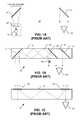
- FIG. 1Aillustrates a first conventional near-to-eye optical system using an input lens and two mirrors.
- FIG. 1Billustrates a second conventional near-to-eye optical system using angle sensitive dichroic mirrors.
- FIG. 1Cillustrates a third conventional near-to-eye optical system using holographic diffraction gratings.
- FIG. 2Ais a cross-sectional view illustrating an image waveguide with minor arrays for generating a near-to-eye image, in accordance with an embodiment of the invention.
- FIG. 2Bis a front perspective view illustrating the image waveguide with mirror arrays for generating a near-to-eye image, in accordance with an embodiment of the invention.
- FIG. 3is a top view illustrating an in-coupling region, in accordance with an embodiment of the invention.
- FIG. 4Ais a top view illustrating an out-coupling region, in accordance with an embodiment of the invention.
- FIG. 4Bis a side view of a portion of the out-coupling region, in accordance with an embodiment of the invention.
- FIG. 5is a flow chart illustrating an example process for fabricating an image waveguide with mirror arrays, in accordance with an embodiment of the invention.
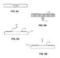
- FIGS. 6A-Dillustrate the example process for fabricating an image waveguide with mirror arrays, in accordance with an embodiment of the invention.
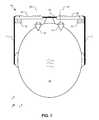
- FIG. 7is a top view of a near-to-eye imaging system using two image waveguides each with mirror arrays, in accordance with an embodiment of the invention.
- Embodiments of an apparatus, system and method for fabrication of a waveguide with embedded mirrorsare described herein.
- numerous specific detailsare set forth to provide a thorough understanding of the embodiments.
- One skilled in the relevant artwill recognize, however, that the techniques described herein can be practiced without one or more of the specific details, or with other methods, components, materials, etc.
- well-known structures, materials, or operationsare not shown or described in detail to avoid obscuring certain aspects.
- FIG. 1Aillustrates a first conventional near-to-eye optical system 101 using an input lens and two mirrors.
- An image source 105outputs an image that is reflected by two mirrors 110 and 115 , which form an image near to eye 120 .
- Image source 105is typically mounted above the head or to the side of the head, while mirrors 110 and 115 bend the image around the front of the viewer's face to their eye 120 . Since the human eye is typically incapable of focusing on objects placed within a few centimeters, this system requires a lens 125 interposed between the first mirror 110 and image source 105 . Lens 125 creates a virtual image that is displaced further back from the eye than the actual location of mirror 115 by positioning image source 105 inside of the focal point f of lens 125 .
- Optical system 101suffers from a relatively small field of view (e.g., approximately 20 degrees) limited by the extent of mirrors 110 and 115 and the bulkiness of lens 125 .
- the field of viewcan be marginally improved by placing minors 110 and 115 within a high index material to compress the angles of incidence, but is still very limited and the thickness of the waveguide rapidly increases to achieve larger fields of view.
- FIG. 1Billustrates a second conventional near-to-eye optical system 102 using angle sensitive dichroic mirrors.
- Optical system 102includes a single in-coupling minor 130 and two out-coupling dichroic mirrors 135 disposed within a waveguide 140 .
- This systemuses collimated input light from virtual images placed at infinity.
- each incident angle of input lightshould correspond to a single output angle of emitted light. Since light can potentially reflect off of output minors 135 on either a downward trajectory (ray segments 145 ) or an upward trajectory (ray segments 150 ), each input angle can potentially result in multiple output angles, thereby destroying the output image.
- optical system 102uses angle sensitive dichroic mirrors 135 that pass light with incident sufficiently close to normal while reflecting light having a sufficiently oblique incidence.
- dichroic mirrors 135that passes some incident angles while reflecting others limits the field of view optical system 102 and the dichroic mirror coating does not provide sharp angular cutoffs, resulting in ghosting effects.
- FIG. 1Cillustrates a third conventional near-to-eye optical system 103 using holographic diffraction gratings.
- Optical system 103is similar to optical system 102 , but uses holographic diffraction gratings 150 in place of mirrors 130 and 135 .
- Diffraction gratings 150are inefficient reflectors, since they only reflect higher order diffractions while passing the first order diffraction, which contains the largest portion of energy in an optical wave front.
- the input and output diffraction gratingsmust be precisely tuned to one another, else the output image will suffer from color separation. Achieving a sufficient match between the input and output gratings 150 requires extreme control over manufacturing tolerances, which is often difficult and costly.
- optical system 103suffers from a limited field of view.
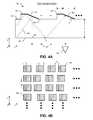
- FIGS. 2A and 2Billustrate an image waveguide 200 with one-dimensional (“1D”) and two-dimensional (“2D”) mirror arrays for generating a near-to-eye image, in accordance with an embodiment of the invention.
- FIG. 2Ais a cross-sectional view while FIG. 2B is a front perspective view of the same.
- the illustrated embodiment of image waveguide 200includes an in-coupling region 205 , an out-coupling region 210 , and an intermediate region 215 .
- the illustrated embodiment of in-coupling region 205includes in-coupling mirror structures 220 .
- the illustrated embodiment of out-coupling region 210includes out-coupling mirror structures 225 and end cap surface 230 .
- image waveguide 200is a single waveguide substrate (e.g., planar waveguide) that receives input light and emits output light from the same side surface of the waveguide substrate.
- Image waveguide 200operates by receiving collimated input light into image waveguide 200 at in-coupling region 205 .
- In-coupling mirror structures 205are orientated to reflect the input light through image waveguide 200 towards out-coupling region 220 .
- the reflected input lightis guided towards out-coupling region 210 by intermediate region 215 .
- In-coupling mirror structures 220include reflective surfaces that are angled oblique to light incident surface 240 .
- in-coupling minor structures 220each include at least one reflective surface angled relative to the input light and sides of image waveguide 200 such that the reflected input light strikes the sides of image waveguide 200 with sufficiently oblique angles that it is guided within image waveguide 200 via total internal reflection (“TIR”).
- TIRtotal internal reflection
- one or more metallic reflective layersare coated along the sides of image waveguide 200 , including intermediate region 215 , to guide the light without need of TIR.
- a combination of both TIR and metallic reflective coatingsmay also be used.
- the guided lighteventually reaches out-coupling region 210 where it is once again reflected by out-coupling mirror structures 225 .
- Out-coupling mirror structures 225are orientated to reflect the guided light for exit out emission surface 245 within out-coupling region 210 towards eye 120 .
- each out-coupling mirror structure 225includes at least one reflective surface that is orientated such that the guided light received from intermediate region 215 strikes the side of image waveguide 200 with an angle sufficiently close to normal such that the light is output from image waveguide 200 towards eye 120 .
- Image waveguide 200may be fabricated of a variety of optically transmissive, light guiding materials, such as polymer, quartz, glass, etc. In one embodiment that uses TIR to guide light through intermediate region 215 , image waveguide 200 is fabricated of a polymer material having an index of refraction of approximately 1.5. The dimensions of image waveguide 200 may be adjusted for a particular application; however, one example dimension set includes A ⁇ 1 mm, B ⁇ 40 mm, C ⁇ 30 mm, D ⁇ 7.5 mm, E ⁇ 8.5 mm. Of course, other dimensions may be used and may vary based on application, aesthetic design choices, intended user size, etc.
- the center-to-center separation distance between the array of in-coupling mirror structures 220 and the array of out-coupling mirror structures 225is configured to match an average inter-papillary distance of all users, children users, or adult users. It should be appreciated that the figures are not drawn to scale.
- the illustrated embodiment of in-coupling region 205includes a continuous 1D array of in-coupling mirror structures 225 each for reflecting a different portion of the input light image.
- FIGS. 2A and 2Billustrates the 1D array as a series of elongated in-coupling mirror structures 220 each having at least one rectangular flat/planar reflective surface orientated obliquely to light incident surface 240 .
- In-coupling mirror structures 220may each be the same length and width or have a variable length and width.
- In-coupling mirror structures 220may be disposed immediately adjacent to each other substantially without intervening or interstitial gaps between adjacent members, or off-set with interstitial gaps.
- in-coupling mirror structures 220may be fabricated as raised mirror structures that rise up from a planar surface (such as front side surface 250 ) in the Z-axis.
- in-coupling mirror structures 220may also be embedded within in-coupling region 205 in a variety of other configurations.
- in-coupling mirror structures 220maybe encased or back filled within a planarization layer for protection.
- in-coupling mirror structures 220have a substantially trapezoidal cross-section (e.g., see FIG. 3 ).
- embodiments of in-coupling mirror structures 220may be implemented with other structures having different cross-sectional shapes and one or more flat reflective surfaces.
- in-coupling mirror structures 220may be fabricated with a raised triangular cross-section having just one reflective surface that is obliquely orientated to light incident surface 240 and/or front side surface 250 .
- FIGS. 2A and 2Billustrate seven in-coupling mirror structures 220 , embodiments may be implemented with fewer or greater numbers of in-coupling mirror structures 220 (e.g., 33 continuous in-coupling mirror structures).
- FIGS. 2A and 2Billustrate in-coupling region 205 as including a 1D array of in-coupling mirror structures
- the 1D array within in-coupling region 205can be replaced with a 2D array of in-coupling mirror structures (not illustrated).
- This alternative 2D array of in-coupling mirror structuresmay be implemented as a continuous 2D array of mirror structures having substantially no interstitial gaps between adjacent mirror structures.
- the 2D array of in-coupling mirror structuresmay include interstitial gaps in one or two dimensions between adjacent in-coupling mirror structures.
- Out-coupling region 210includes a 2D array of out-coupling mirror structures 225 each for reflecting a different portion of the guided light for emission from image waveguide 200 .
- FIGS. 2A and 2Billustrate each out-coupling mirror structure 225 as having two rectangular flat/planar reflective surfaces: one orientated obliquely to emission surface 245 and the other orientated substantially parallel with emission surface 245 .
- These structuresmay be fabricated as raised mirror structures that rise up from a planar surface (such as front side surface 250 ) in the Z-axis.
- the in-coupling and out-coupling mirror structuresdo not extend into the waveguide along the z-axis, but rather rise up from front side surface 250 .
- out-coupling mirror structures 225may also be embedded within out-coupling region 210 in a variety of other configurations, as long as, they are offset from one another to each reflect a different portion of the guided light.
- out-coupling mirror structures 225maybe encased or back filled within a planarization layer for protection.
- the planarization layer that overlays the 2D arraymay also include anti-reflective (“AR”) properties.
- the out-coupling mirror structureshave a substantially trapezoidal cross-section (e.g., see FIG. 4A ).
- embodiments of out-coupling mirrors 225may be implemented with other structures having different cross-sectional shapes and one or more flat reflective surfaces.
- in-coupling mirror structures 220 of the 1D arrayhave an elongated height (dimension B) that is substantially equivalent to an overall height of the 2D array along the X-axis.
- the inter-wedge spacing between out-coupling mirror structures 225may vary periodically or aperiodically along the Y-axis while remaining constant along the X-axis.
- the spacing or interstitial gaps between adjacent out-coupling mirror structures 225may be selected to permit external light to pass through image waveguide 200 between out-coupling mirror structures 225 and reach the eye 120 .
- out-coupling region 210is partially transparent and eye 120 is able to see a real world image from the external light passing through image waveguide 200 augmented by another image guided through image waveguide 200 .
- the other imagemay typically be CGI for superimposing over a user's real world vision.
- the degree of transparencymay be controlled based on a ratio of areas of out-coupling mirror structures 225 and intervening gaps 260 between out-coupling minor structures 225 .
- End cap surface 230inhibits backward reflections propagating towards in-coupling region 205 by discouraging reflections off the right distal end of image waveguide 200 .
- end cap surface 230is implemented as a light absorbing surface (e.g., a dark matte surface).
- end cap surface 230is implemented as a light scattering surface (e.g., a rough, diffusive surface).
- end cap surface 230is an AR surface/coating to permit guided light that reaches the distal end to pass out of the waveguide with reduced back reflections.
- end cap surface 230may include combinations of the above possible embodiments.
- waveguide 200may be fabricated as a single piece planar waveguide having surface 250 along which in-coupling mirror structures 220 and out-coupling mirror structures 225 are disposed.
- surface 250is substantially parallel and opposite to surfaces 240 and 245 through which the input light enters and the output light is emitted.
- waveguide 200is a single piece injection molded planar waveguide.
- FIG. 3is a top view illustrating in-coupling mirror structures 300 , in accordance with an embodiment of the invention.
- In-coupling mirror structures 300represent one possible implementation of in-coupling mirror structures 220 .
- the illustrated embodiment of in-coupling mirror structures 300each have a substantially trapezoidal cross-section with a flat reflective surface 305 orientated obliquely to light incident surface 340 and a flat surface 310 orientated substantially parallel to light incident surface 340 . These structures are disposed along a planar surface 315 and laterally offset from one another to reflect a different portion of input light 320 .
- the illustrated embodimentis a continuous 1D array of in-coupling mirror structures 300 with substantially no intervening gaps, in other embodiments inter-wedge gaps may be included.
- surfaces 305 and 310are reflective, non-optically-transmissive surfaces.
- surfaces 305 and 310may be fabricated with a reflective metal film, such as, aluminum, nickel, gold, chromium, tin, or otherwise.
- reflective surface 305is coated with a non-optically transmissive reflective layer (e.g., metallic coating), while surface 310 is not.
- reflective surfaces 305 and 310are index of refraction interfaces that reflect light via TIR.
- surface 310is omitted (e.g., triangular cross-section of in-coupling mirror structures 300 ) or coated with an AR material so that it is substantially not reflective, but rather passes input light 320 incident upon surface 310 with a substantially normal trajectory to surface 310 .
- in-coupling mirror structures 300may be adjusted for a particular application; however, an example dimension set includes F ⁇ 174 ⁇ m, G ⁇ 52 ⁇ m, and H ⁇ 30°. Of course, other dimensions/angles may be used. It should be appreciated that the figures are not drawn to scale.
- the inter-wedge separation spacingmay be selected for a variety characteristics, including image resolution, image brightness, transparency of in-coupling region, etc. However, an additional consideration is based upon the expected incident angles of input light 320 and angle H.
- FIGS. 4A and 4Billustrate a discrete 2D array of out-coupling mirror structures 400 , in accordance with an embodiment of the invention.
- Out-coupling mirror structures 400represent one possible implementation of out-coupling mirror structures 225 illustrated in FIGS. 2A and 2B .
- the illustrated embodiment of out-coupling mirror structures 400each have a trapezoidal cross-section with two flat reflective surfaces: surface 405 orientated obliquely to emission surface 445 and surface 410 orientated substantially parallel with emission surface 445 .
- These discrete structuresare disposed along, and rise up from, a planar surface 415 and offset from one another to reflect a different portion of guided light 420 .
- reflective surfaces 405 and 410are non-optically-transmissive surfaces.
- reflective surfaces 405 and 410may be fabricated as a reflective metal film, such as, aluminum, nickel, gold, chromium, tin, or otherwise.
- reflective surfaces 405 and 410are fabricated using a dichroic film, which enables wavelength selectivity for specific transmission and reflection behavior.
- reflective surfaces 405 and 410are index of refraction interfaces that reflect light via TIR.
- the dimensions of out-coupling mirror structures 400may be adjusted for a particular application; however, an example dimension set may include I ⁇ 174 ⁇ m, J ⁇ 52 ⁇ m, and K ⁇ 30°. Of course, other dimensions/angles may be used. It should be appreciated that the figures are not drawn to scale.
- reflective surface 410is provided to increase the field of view and spread the output light over a greater extent of emission surface 445 .
- guided light 420propagates down image waveguide 200 from intermediate region 215 into out-coupling region 210 , some rays will immediately strike one of the oblique reflective surfaces 405 located closer to intermediate region 215 .
- These light raysare reflected with an angle of incidence (angle M) sufficiently large (or sufficiently close to normal with respect to emission surface 445 ) that they exit image waveguide 200 towards eye 120 as the output light.
- angle Mangle of incidence
- other rays of guided light 420 entering into out-coupling region 210 from intermediate region 215strike one of the substantially parallel reflective surfaces 410 .
- Reflective surfaces 410operate to increase the output efficiency of image waveguide 200 and extend the emission field of view and eye box (e.g., 15° field of view and 5 ⁇ 10 mm eyebox). In this manner, oblique reflective surfaces 405 may be thought of as exit mirrors while substantially parallel reflective surfaces 410 may be thought of as propagation mirrors.
- out-coupling region 210is partially transparent to pass external light 425 through surfaces 415 and 445 to eye 120 . Since reflective surfaces 405 and 410 may be fabricated of non-optically-transmissive material, the degree of transparency of out-coupling region 210 can be adjusted by appropriate selection of dimensions O and N (see FIG. 4B ) between adjacent out-coupling mirror structures 400 and/or adjustment of dimensions J and I of the mirror structures themselves. By increasing the proportion of unobstructed surface 415 that falls between out-coupling mirror structures 400 , the transparency of out-coupling region 210 can be increased. In one embodiment, an AR coating may be applied to planar surface 415 in the out-coupling region 210 to reduce reflections of external light 425 when entering image waveguide 200 .
- the 2D array of out-coupling mirror structures 400may be spaced according to a variety of different schemes.
- the vertical spacing Mmay be a constant value (e.g., N ⁇ 100 ⁇ m), while the horizontal spacing O may vary.
- the variable horizontal spacingmay change in a periodic pattern or an aperiodic pattern.
- horizontal spacing Ostarts at 150 ⁇ m and decrements by 5 ⁇ m for each consecutive wedge until 0 reaches 100 ⁇ m, and then starts back at 150 ⁇ m.
- start, stop, and decrement valuesmay be used.
- the aperiodic spacing patterncontinues from the last wedge in an immediately previous row to the first wedge of the next row.
- both vertical and/or horizontal spacingcan be constant, random, periodic, or aperiodic, and other spacing schemes may be implemented as well.
- one benefit to selecting a variably changing spacingis to eliminate the perception of a repeating pattern in the output light image, while also permitting external light to pass through out-coupling region 210 to eye 120 .
- FIGS. 4A and 4Billustrates each out-coupling mirror structure 400 as being replicas of each other
- the size, shape, and pitchi.e., angle of obliqueness
- the size, shape, and pitchmay vary per mirror structure, per row of the 2D array, per column of the 2D array, per localized region of the 2D array or otherwise.
- These variants in size, shape, and pitchmay be selected to enhance resolution or brightness of the reflected CGI image at the center or peripheral of the 2D array.
- Such design variationsmay be implemented to provide an overall even CGI image or to increase resolution at the center of the user's field of view where eye acuity is greatest.
- the density of mirror structuresmay be increased in the center of the 2D array relative to the periphery to improve center resolution or reciprocally increased at the periphery of the 2D array relative to the center to improve peripheral vision of the CGI image guided by image waveguide 200 (assuming alignment between the center of the 2D array and the natural eye position).
- FIG. 5is a flow chart illustrating an example process 500 for fabricating image waveguide 200 , in accordance with an embodiment of the invention.
- Process 500describes an injection molding fabrication process using thermal plastics.
- thermal plasticssuch as thermal plastics.
- photolithography and multiple flood exposuresmay be used to pattern the 1D and 2D arrays onto the surface of a waveguiding substrate.
- Process 500is described with reference to FIGS. 6A-D .
- the order in which some or all of the process blocks appear in process 500should not be deemed limiting. Rather, one of ordinary skill in the art having the benefit of the present disclosure will understand that some of the process blocks may be executed in a variety of orders not illustrated.
- a metal injection mold 605is fabricated.
- the inside surfaces of mold 605includes the surface features necessary to form the raised in-coupling and out-coupling mirror structures.
- a polymer or thermal plastic 610is injected into the mold at an elevated temperature that permits the polymer or thermal plastic to flow and assume the internal shape of mold 605 .
- Mold 605is cooled causing the thermal plastic to harden.
- the thermal plasticis a polymer material with an index of refraction of approximately 1.5.
- surfaces 620are coated with a non-optically transmissive reflective material (e.g., metal).
- a metal layermay be disposed over the entire side 625 of waveguide member 615 and then patterned using lithograph and the excess material washed away using liftoff techniques leaving just surfaces 620 covered.
- intermediate region 215may also be coated with metal to augment the light guiding characteristics within this region. In some embodiments that use TIR exclusively for all reflective surfaces, process block 515 may be skipped.
- a planarized protection layer 630may be disposed over side 625 to protect the 1D and 2D arrays.
- Planarized protection layer 630may be formed of the same material as waveguide member 615 (e.g., when surfaces 620 are coated with metal) or formed of another transparent material having a different index of refraction than the waveguide member 615 .
- Planarized protection layer 630may be planarized using a chemical mechanical polishing (“CMP”).
- CMPchemical mechanical polishing
- planarized protection layer 630also operates as an AR layer or alternatively is coated with an AR coating.
- planarized protection layer 630is a complementary molded piece with a planar top surface that fits over the raised mirror structures.
- process block 520is also optional.
- FIG. 7is a top view of a demonstrative near-to-eye imaging system 700 , in accordance with an embodiment of the invention.
- the illustrated embodiment of imaging system 700includes two image waveguides 200 , a frame including a nose assembly 705 , left ear assembly 710 , and right ear assembly 715 , and two image sources 720 and 725 .
- the two image waveguides 200are secured into an eye glass arrangement that can be worn on a head 730 of a user.
- the left and right ear assemblies 710 and 715rest over the user's ears while nose assembly 705 rests over the user's nose.
- the frame assemblyis shaped and sized to position out-coupling region 210 of each image waveguide 200 in front of a corresponding eye 120 of the user with the emission surfaces facing eyes 120 .
- each image waveguide 200is partially transparent and permits the user to see a real world image via external light 425 .
- Left and right (binocular embodiment) CGIsare generated by image sources 720 and 725 , respectively.
- image sources 720 and 725are liquid crystal on silicon (“LCoS”) based pico-projectors that use laser diodes or LEDs and emit collimated light.
- LCDliquid crystal on silicon
- other display technologymay be used.
- the CGI output by image sources 720 and 725is launched into their respective image waveguides 200 at in-coupling regions 205 , guided through intermediate regions 215 , and emitted from out-coupling regions 210 near-to-eyes 120 . Since image waveguides 200 preserve a one-to-one relation of input light angles to output light angles, the output light is also collimated and therefore virtually projected at near infinity. Although the human eye is typically incapable of bring objects within a few centimeters into focus, since the output light is virtually displayed at near infinity, the image is readily in focus.
- the CGIis seen by the user as a virtual image superimposed over the real world as an augmented reality.
- FIG. 7illustrates image sources 720 and 725 as projecting images normal to image waveguides 200
- optical elementse.g., lenses, mirrors, etc.
- the CGI lightmay be launched into in-coupling regions 205 at oblique angles.
Landscapes
- Physics & Mathematics (AREA)
- General Physics & Mathematics (AREA)
- Optics & Photonics (AREA)
- Optical Couplings Of Light Guides (AREA)
Abstract
Description
This disclosure relates generally to the field of optics, and in particular but not exclusively, relates to near-to-eye optical systems.
A head mounted display (“HMD”) is a display device worn on or about the head. HMDs usually incorporate some sort of near-to-eye optical system to display an image within a few centimeters of the human eye. Single eye displays are referred to as monocular HMDs while dual eye displays are referred to as binocular HMDs. Some HMDs display only a computer generated image (“CGI”), while other types of HMDs are capable of superimposing CGI over a real-world view. This latter type of HMD is often referred to as augmented reality because the viewer's image of the world is augmented with an overlaying CGI, also referred to as a heads-up display (“HUD”).
HMDs have numerous practical and leisure applications. Aerospace applications permit a pilot to see vital flight control information without taking their eye off the flight path. Public safety applications include tactical displays of maps and thermal imaging. Other application fields include video games, transportation, and telecommunications. There is certain to be new found practical and leisure applications as the technology evolves; however, many of these applications are limited due to the cost, size, field of view, and efficiency of conventional optical systems used to implemented existing HMDs.
Implementations of techniques, apparatuses, and systems are provided for an image waveguide for use in a heads-up-display capable of providing an augmented reality to a user. In one aspect, the image waveguide includes first and second surfaces being substantially parallel and opposite to each other, the image waveguide including an in-coupling region for receiving input light into the image waveguide through the second surface and an out-coupling region for emitting output light from the image waveguide out the second surface; a one dimensional (“1D”) array of in-coupling mirror structures disposed in or on the image waveguide along the first surface at the in-coupling region of the image waveguide and orientated to reflect the input light, after entering through the second surface, along the image waveguide towards the out-coupling region as guided light; and a two dimensional (“2D”) array of out-coupling mirror structures disposed in or on the image waveguide along the first surface at the out-coupling region of the image waveguide and orientated to reflect the guided light out of the image waveguide as the output light.
These and other aspects and embodiments are described in detail in the drawings, the description, and the claims.
Non-limiting and non-exhaustive embodiments of the invention are described with reference to the following figures, wherein like reference numerals refer to like parts throughout the various views unless otherwise specified.
Embodiments of an apparatus, system and method for fabrication of a waveguide with embedded mirrors are described herein. In the following description numerous specific details are set forth to provide a thorough understanding of the embodiments. One skilled in the relevant art will recognize, however, that the techniques described herein can be practiced without one or more of the specific details, or with other methods, components, materials, etc. In other instances, well-known structures, materials, or operations are not shown or described in detail to avoid obscuring certain aspects.
Reference throughout this specification to “one embodiment” or “an embodiment” means that a particular feature, structure, or characteristic described in connection with the embodiment is included in at least one embodiment of the present invention. Thus, the appearances of the phrases “in one embodiment” or “in an embodiment” in various places throughout this specification are not necessarily all referring to the same embodiment. Furthermore, the particular features, structures, or characteristics may be combined in any suitable manner in one or more embodiments.
The illustrated embodiment of in-coupling region 205 includes a continuous 1D array of in-coupling mirror structures 225 each for reflecting a different portion of the input light image.FIGS. 2A and 2B illustrates the 1D array as a series of elongated in-coupling mirror structures 220 each having at least one rectangular flat/planar reflective surface orientated obliquely tolight incident surface 240. In-coupling mirror structures 220 may each be the same length and width or have a variable length and width. In-coupling mirror structures 220 may be disposed immediately adjacent to each other substantially without intervening or interstitial gaps between adjacent members, or off-set with interstitial gaps. These structures may be fabricated as raised mirror structures that rise up from a planar surface (such as front side surface250) in the Z-axis. However, it should be appreciated that in-coupling mirror structures 220 may also be embedded within in-coupling region 205 in a variety of other configurations. For example, in-coupling mirror structures 220 maybe encased or back filled within a planarization layer for protection. In the illustrated embodiment, in-coupling mirror structures 220 have a substantially trapezoidal cross-section (e.g., seeFIG. 3 ). However, embodiments of in-coupling mirror structures 220 may be implemented with other structures having different cross-sectional shapes and one or more flat reflective surfaces. For example, in-coupling mirror structures 220 may be fabricated with a raised triangular cross-section having just one reflective surface that is obliquely orientated tolight incident surface 240 and/orfront side surface 250. Furthermore, althoughFIGS. 2A and 2B illustrate seven in-coupling mirror structures 220, embodiments may be implemented with fewer or greater numbers of in-coupling mirror structures220 (e.g., 33 continuous in-coupling mirror structures).
AlthoughFIGS. 2A and 2B illustrate in-coupling region 205 as including a 1D array of in-coupling mirror structures, in alternative embodiments, the 1D array within in-coupling region 205 can be replaced with a 2D array of in-coupling mirror structures (not illustrated). This alternative 2D array of in-coupling mirror structures may be implemented as a continuous 2D array of mirror structures having substantially no interstitial gaps between adjacent mirror structures. In yet other embodiments, the 2D array of in-coupling mirror structures may include interstitial gaps in one or two dimensions between adjacent in-coupling mirror structures.
Out-coupling region 210 includes a 2D array of out-coupling mirror structures 225 each for reflecting a different portion of the guided light for emission fromimage waveguide 200.FIGS. 2A and 2B illustrate each out-coupling mirror structure 225 as having two rectangular flat/planar reflective surfaces: one orientated obliquely toemission surface 245 and the other orientated substantially parallel withemission surface 245. These structures may be fabricated as raised mirror structures that rise up from a planar surface (such as front side surface250) in the Z-axis. In the illustrated embodiment, the in-coupling and out-coupling mirror structures do not extend into the waveguide along the z-axis, but rather rise up fromfront side surface 250. However, it should be appreciated that out-coupling mirror structures 225 may also be embedded within out-coupling region 210 in a variety of other configurations, as long as, they are offset from one another to each reflect a different portion of the guided light. For example, out-coupling mirror structures 225 maybe encased or back filled within a planarization layer for protection. In one embodiment, the planarization layer that overlays the 2D array may also include anti-reflective (“AR”) properties. In one embodiment, the out-coupling mirror structures have a substantially trapezoidal cross-section (e.g., seeFIG. 4A ). However, embodiments of out-coupling mirrors225 may be implemented with other structures having different cross-sectional shapes and one or more flat reflective surfaces. Furthermore, althoughFIGS. 2A and 2B illustrate30 out-coupling mirror structures 225, embodiments may be implemented with fewer or greater numbers of offset out-coupling mirror structures225 (e.g., 25 wedges along the Y-axis and 17 wedges along the X-axis for a total of 425 out-coupling mirror structures). In one embodiment, in-coupling mirror structures 220 of the 1D array have an elongated height (dimension B) that is substantially equivalent to an overall height of the 2D array along the X-axis.
As discussed in further detail below, in one embodiment, the inter-wedge spacing between out-coupling mirror structures 225 may vary periodically or aperiodically along the Y-axis while remaining constant along the X-axis. The spacing or interstitial gaps between adjacent out-coupling mirror structures 225 may be selected to permit external light to pass throughimage waveguide 200 between out-coupling mirror structures 225 and reach theeye 120. In this regard, out-coupling region 210 is partially transparent andeye 120 is able to see a real world image from the external light passing throughimage waveguide 200 augmented by another image guided throughimage waveguide 200. The other image may typically be CGI for superimposing over a user's real world vision. The degree of transparency may be controlled based on a ratio of areas of out-coupling mirror structures 225 and interveninggaps 260 between out-couplingminor structures 225.
In one embodiment,waveguide 200 may be fabricated as a single piece planarwaveguide having surface 250 along which in-coupling mirror structures 220 and out-coupling mirror structures 225 are disposed. In the illustrated embodiment,surface 250 is substantially parallel and opposite tosurfaces waveguide 200 is a single piece injection molded planar waveguide.
In one embodiment, surfaces305 and310 are reflective, non-optically-transmissive surfaces. For example, surfaces305 and310 may be fabricated with a reflective metal film, such as, aluminum, nickel, gold, chromium, tin, or otherwise. In one embodiment,reflective surface 305 is coated with a non-optically transmissive reflective layer (e.g., metallic coating), whilesurface 310 is not. In another embodiment,reflective surfaces surface 310 is omitted (e.g., triangular cross-section of in-coupling mirror structures300) or coated with an AR material so that it is substantially not reflective, but rather passes input light320 incident uponsurface 310 with a substantially normal trajectory tosurface 310.
The dimensions of in-coupling mirror structures 300 may be adjusted for a particular application; however, an example dimension set includes F≈174 μm, G≈52 μm, and H≈30°. Of course, other dimensions/angles may be used. It should be appreciated that the figures are not drawn to scale. The inter-wedge separation spacing may be selected for a variety characteristics, including image resolution, image brightness, transparency of in-coupling region, etc. However, an additional consideration is based upon the expected incident angles ofinput light 320 and angle H.
In the illustrated embodiment of out-coupling mirror structures 400,reflective surface 410 is provided to increase the field of view and spread the output light over a greater extent ofemission surface 445. As guidedlight 420 propagates downimage waveguide 200 fromintermediate region 215 into out-coupling region 210, some rays will immediately strike one of the obliquereflective surfaces 405 located closer tointermediate region 215. These light rays are reflected with an angle of incidence (angle M) sufficiently large (or sufficiently close to normal with respect to emission surface445) that they exitimage waveguide 200 towardseye 120 as the output light. However, other rays of guided light420 entering into out-coupling region 210 fromintermediate region 215 strike one of the substantially parallelreflective surfaces 410. These rays are reflected with an angle of incidence (angle L) sufficiently small that they are reflected offemission surface 445 and continue propagating down out-coupling region 210 until they strike an obliquereflective surface 405 andexit image waveguide 200. Thus, the output light is laterally extended over a larger area ofemission surface 445.Reflective surfaces 410 operate to increase the output efficiency ofimage waveguide 200 and extend the emission field of view and eye box (e.g., 15° field of view and 5×10 mm eyebox). In this manner, obliquereflective surfaces 405 may be thought of as exit mirrors while substantially parallelreflective surfaces 410 may be thought of as propagation mirrors.
In one embodiment, out-coupling region 210 is partially transparent to passexternal light 425 throughsurfaces eye 120. Sincereflective surfaces coupling region 210 can be adjusted by appropriate selection of dimensions O and N (seeFIG. 4B ) between adjacent out-coupling mirror structures 400 and/or adjustment of dimensions J and I of the mirror structures themselves. By increasing the proportion ofunobstructed surface 415 that falls between out-coupling mirror structures 400, the transparency of out-coupling region 210 can be increased. In one embodiment, an AR coating may be applied toplanar surface 415 in the out-coupling region 210 to reduce reflections ofexternal light 425 when enteringimage waveguide 200.
Referring toFIG. 4B , the 2D array of out-coupling mirror structures 400 may be spaced according to a variety of different schemes. In one embodiment, the vertical spacing M may be a constant value (e.g., N≈100 μm), while the horizontal spacing O may vary. The variable horizontal spacing may change in a periodic pattern or an aperiodic pattern. For example, in one embodiment, horizontal spacing O starts at 150 μm and decrements by 5 μm for each consecutive wedge until 0 reaches 100 μm, and then starts back at 150 μm. Of course other start, stop, and decrement values may be used. In the illustrated embodiment, the aperiodic spacing pattern continues from the last wedge in an immediately previous row to the first wedge of the next row. Thus, while the leftmost wedge in each row begins at the same lateral position, the spacing after the first wedge begins where the pattern spacing of the last wedge in the previous row finished. Of course, in other embodiments, the first wedge in each row need not be aligned to the same starting point and/or the variable spacing may restart on each row. In other embodiments, both vertical and/or horizontal spacing can be constant, random, periodic, or aperiodic, and other spacing schemes may be implemented as well. However, in general, one benefit to selecting a variably changing spacing is to eliminate the perception of a repeating pattern in the output light image, while also permitting external light to pass through out-coupling region 210 toeye 120.
AlthoughFIGS. 4A and 4B illustrates each out-coupling mirror structure 400 as being replicas of each other, in some embodiments, the size, shape, and pitch (i.e., angle of obliqueness) may vary per mirror structure, per row of the 2D array, per column of the 2D array, per localized region of the 2D array or otherwise. These variants in size, shape, and pitch may be selected to enhance resolution or brightness of the reflected CGI image at the center or peripheral of the 2D array. Such design variations may be implemented to provide an overall even CGI image or to increase resolution at the center of the user's field of view where eye acuity is greatest. Thus, in one embodiment, the density of mirror structures may be increased in the center of the 2D array relative to the periphery to improve center resolution or reciprocally increased at the periphery of the 2D array relative to the center to improve peripheral vision of the CGI image guided by image waveguide200 (assuming alignment between the center of the 2D array and the natural eye position).
In aprocess block 505, ametal injection mold 605 is fabricated. The inside surfaces ofmold 605 includes the surface features necessary to form the raised in-coupling and out-coupling mirror structures. In aprocess block 510, a polymer orthermal plastic 610 is injected into the mold at an elevated temperature that permits the polymer or thermal plastic to flow and assume the internal shape ofmold 605.Mold 605 is cooled causing the thermal plastic to harden. In one embodiment, the thermal plastic is a polymer material with an index of refraction of approximately 1.5. Once cooled,mold 605 is opened and thewaveguide member 615 extracted.
In aprocess block 515,surfaces 620 are coated with a non-optically transmissive reflective material (e.g., metal). In one embodiment, a metal layer may be disposed over theentire side 625 ofwaveguide member 615 and then patterned using lithograph and the excess material washed away using liftoff techniques leaving just surfaces620 covered. In one embodiment,intermediate region 215 may also be coated with metal to augment the light guiding characteristics within this region. In some embodiments that use TIR exclusively for all reflective surfaces, process block515 may be skipped.
Finally, in aprocess block 520, aplanarized protection layer 630 may be disposed overside 625 to protect the 1D and 2D arrays.Planarized protection layer 630 may be formed of the same material as waveguide member615 (e.g., when surfaces620 are coated with metal) or formed of another transparent material having a different index of refraction than thewaveguide member 615.Planarized protection layer 630 may be planarized using a chemical mechanical polishing (“CMP”). In one embodiment,planarized protection layer 630 also operates as an AR layer or alternatively is coated with an AR coating. In yet another embodiment,planarized protection layer 630 is a complementary molded piece with a planar top surface that fits over the raised mirror structures. Of course, process block520 is also optional.
The twoimage waveguides 200 are secured into an eye glass arrangement that can be worn on ahead 730 of a user. The left andright ear assemblies nose assembly 705 rests over the user's nose. The frame assembly is shaped and sized to position out-coupling region 210 of eachimage waveguide 200 in front of acorresponding eye 120 of the user with the emissionsurfaces facing eyes 120.
The illustrated embodiment is capable of displaying an augmented reality to the user. As such, out-coupling region 210 of eachimage waveguide 200 is partially transparent and permits the user to see a real world image viaexternal light 425. Left and right (binocular embodiment) CGIs are generated byimage sources image sources image sources respective image waveguides 200 at in-coupling regions 205, guided throughintermediate regions 215, and emitted from out-coupling regions 210 near-to-eyes 120. Sinceimage waveguides 200 preserve a one-to-one relation of input light angles to output light angles, the output light is also collimated and therefore virtually projected at near infinity. Although the human eye is typically incapable of bring objects within a few centimeters into focus, since the output light is virtually displayed at near infinity, the image is readily in focus. The CGI is seen by the user as a virtual image superimposed over the real world as an augmented reality.
AlthoughFIG. 7 illustratesimage sources waveguides 200, in other embodiments, optical elements (e.g., lenses, mirrors, etc.) maybe placed betweenimage sources image waveguides 200, such that the CGI light may be launched into in-coupling regions 205 at oblique angles.
The above description of illustrated embodiments of the invention, including what is described in the Abstract, is not intended to be exhaustive or to limit the invention to the precise forms disclosed. While specific embodiments of, and examples for, the invention are described herein for illustrative purposes, various modifications are possible within the scope of the invention, as those skilled in the relevant art will recognize.
These modifications can be made to the invention in light of the above detailed description. The terms used in the following claims should not be construed to limit the invention to the specific embodiments disclosed in the specification. Rather, the scope of the invention is to be determined entirely by the following claims, which are to be construed in accordance with established doctrines of claim interpretation.
Claims (20)
1. An optical apparatus for a heads up display, the optical apparatus comprising:
a waveguide including first and second surfaces being substantially parallel and opposite to each other, the waveguide including an in-coupling region for receiving input light into the waveguide through the second surface and an out-coupling region for emitting output light from the waveguide out the second surface;
a one dimensional (“1D”) array of in-coupling mirror structures disposed in or on the waveguide along the first surface at the in-coupling region of the waveguide and orientated to reflect the input light, after entering through the second surface, along the waveguide towards the out-coupling region as guided light; and
a two dimensional (“2D”) array of out-coupling mirror structures disposed in or on the waveguide along the first surface at the out-coupling region of the waveguide and orientated to reflect the guided light out of the waveguide as the output light.
2. The optical apparatus ofclaim 1 ,
wherein the 1D and 2D arrays both comprise raised mirror structures that are disposed on and rise from the first surface of the waveguide opposite to the second surface of the waveguide through which the input light is incident and the output light is emitted,
wherein the raised mirror structures of the 1D array are laterally offset from each other along the first surface in a first dimension to each reflect a different portion of the input light, and
wherein the raised mirror structures of the 2D array are laterally offset from each other along the first surface in the first dimension and a second dimension.
3. The optical apparatus ofclaim 2 , wherein each of the raised mirror structures of at least one of the 1D array or the 2D array comprises:
a first reflective surface orientated obliquely to the second surface; and
a second reflective surface orientated substantially parallel to the second surface.
4. The optical apparatus ofclaim 3 , wherein at least one of the first or second reflective surfaces comprises a metallic layer disposed on the raised mirror structures of the at least one of the 1D or 2D arrays.
5. The optical apparatus ofclaim 2 , further comprising a planarization layer fitted over the 1D and 2D arrays and the first surface of the waveguide, wherein the planarization layer comprises a molded element having a complementary surface that fits to the raised mirror structures of the 1D and 2D arrays.
6. The optical apparatus ofclaim 1 , wherein the out-coupling mirror structures have a variable spacing between adjacent ones of the out-coupling mirror structures along a first axis of the 2D array.
7. The optical apparatus ofclaim 6 , wherein the out-coupling mirror structures have a fixed spacing between adjacent ones of the out-coupling mirror structures along a second axis of the 2D array.
8. The optical apparatus ofclaim 6 , wherein the out-coupling mirror structures have an aperiodic spacing between adjacent ones of the out-coupling mirror structures along the first axis of the 2D array.
9. The optical apparatus ofclaim 1 , wherein each of the out-coupling mirror structures of the 2D array comprises:
a first reflective surface that is non-optically transmissive and orientated to reflect the guided light as the output light for emission from the out-coupling region; and
a second reflective surface that is non-optically transmissive and orientated to reflect the guided light for propagation further along the out-coupling region of the waveguide prior to emission from the waveguide,
wherein the first reflective surface is orientated to form an oblique angle with the second surface of the waveguide where the output light emerges from the out-coupling region,
wherein the second reflective surface is orientated substantially parallel to the second surface of the waveguide where the output light emerges.
10. The optical apparatus ofclaim 1 , wherein the out-coupling mirror structures of the 2D array comprise metal reflective structures offset from one another with interstitial gaps such that the out-coupling region is partially transparent and permits external light to pass through the out-coupling region in the interstitial gaps between the out-coupling mirror structures.
11. The optical apparatus ofclaim 1 , wherein each of the in-coupling mirror structures of the 1D array has an elongated height along a first axis that is substantially equivalent to an overall height of the 2D array along the first axis.
12. The optical apparatus ofclaim 1 , wherein the in-coupling mirror structures of the 1D array are disposed in columns substantially without interstitial gaps along a plane.
13. The optical apparatus ofclaim 1 , wherein the waveguide includes an intermediate region disposed between the in-coupling region and the out-coupling region for guiding the guided light between the in-coupling region and the out-coupling region via total internal reflection.
14. The optical apparatus ofclaim 1 , wherein the waveguide further includes:
an intermediate region disposed between the in-coupling region and the out-coupling region for guiding the guided light between the in-coupling region and the out-coupling region; and
at least one metallic reflective layer disposed along a side of the intermediate region, wherein the intermediate region guides the guided light at least partially by reflection off of the metallic reflective layer.
15. The optical apparatus ofclaim 1 , further comprising at least one of a light absorbing surface, an anti-reflective surface, or a light scattering surface disposed on an end region of the waveguide adjacent to the out-coupling region to inhibit the guided light from reflecting back down the waveguide towards the in-coupling region.
16. The optical apparatus ofclaim 1 , wherein the waveguide comprises a single piece injection molded polymer element.
17. A head mounted display for rendering an augmented reality to a user, the head mounted display comprising:
a pair of waveguides each including:
first and second surfaces being substantially parallel and opposite to each other;
an in-coupling region for receiving input light through the second surface and an out-coupling region for emitting output light out the second surface;
a one dimensional (“1D) array of in-coupling mirror structures disposed along the first surface at the in-coupling region and orientated to reflect the input light, after entering through the second surface, towards the out-coupling region as guided light; and
a two dimensional (“2D”) array of out-coupling mirror structures disposed along the first surface at the out-coupling region and orientated to reflect the guided light out of the waveguide through the second surface to an eye of the user as the output light;
a pair of image sources each positioned to launch a computer generated image into the in-coupling region of a corresponding one of the waveguides; and
a frame assembly to support the pair of waveguides and the pair of image sources for wearing on a head of the user.
18. The head mounted display ofclaim 17 , wherein the 1D and 2D arrays both comprise raised mirror structures that are disposed on and rise from the first surface of the waveguide opposite to the second surface of the waveguide through which the input light is incident and the output light is emitted.
19. The head mounted display ofclaim 18 , wherein each of the raised mirror structures of at least one of the 1D array or the 2D array comprises:
a first reflective surface orientated obliquely to the second surface; and
a second reflective surface orientated substantially parallel to the second surface.
20. The head mounted display ofclaim 17 ,
wherein the out-coupling mirror structures have a variable spacing between adjacent ones of the out-coupling mirror structures along a first axis of the 2D array, and
wherein the out-coupling mirror structures have a fixed spacing between adjacent ones of the out-coupling mirror structures along a second axis of the 2D array.
Priority Applications (2)
| Application Number | Priority Date | Filing Date | Title |
|---|---|---|---|
| US13/078,630US8189263B1 (en) | 2011-04-01 | 2011-04-01 | Image waveguide with mirror arrays |
| US13/457,151US8446675B1 (en) | 2011-04-01 | 2012-04-26 | Image waveguide with mirror arrays |
Applications Claiming Priority (1)
| Application Number | Priority Date | Filing Date | Title |
|---|---|---|---|
| US13/078,630US8189263B1 (en) | 2011-04-01 | 2011-04-01 | Image waveguide with mirror arrays |
Related Child Applications (1)
| Application Number | Title | Priority Date | Filing Date |
|---|---|---|---|
| US13/457,151ContinuationUS8446675B1 (en) | 2011-04-01 | 2012-04-26 | Image waveguide with mirror arrays |
Publications (1)
| Publication Number | Publication Date |
|---|---|
| US8189263B1true US8189263B1 (en) | 2012-05-29 |
Family
ID=46086319
Family Applications (2)
| Application Number | Title | Priority Date | Filing Date |
|---|---|---|---|
| US13/078,630ActiveUS8189263B1 (en) | 2011-04-01 | 2011-04-01 | Image waveguide with mirror arrays |
| US13/457,151Expired - Fee RelatedUS8446675B1 (en) | 2011-04-01 | 2012-04-26 | Image waveguide with mirror arrays |
Family Applications After (1)
| Application Number | Title | Priority Date | Filing Date |
|---|---|---|---|
| US13/457,151Expired - Fee RelatedUS8446675B1 (en) | 2011-04-01 | 2012-04-26 | Image waveguide with mirror arrays |
Country Status (1)
| Country | Link |
|---|---|
| US (2) | US8189263B1 (en) |
Cited By (180)
| Publication number | Priority date | Publication date | Assignee | Title |
|---|---|---|---|---|
| US8446675B1 (en) | 2011-04-01 | 2013-05-21 | Google Inc. | Image waveguide with mirror arrays |
| US8467133B2 (en) | 2010-02-28 | 2013-06-18 | Osterhout Group, Inc. | See-through display with an optical assembly including a wedge-shaped illumination system |
| US8472120B2 (en) | 2010-02-28 | 2013-06-25 | Osterhout Group, Inc. | See-through near-eye display glasses with a small scale image source |
| US8477425B2 (en) | 2010-02-28 | 2013-07-02 | Osterhout Group, Inc. | See-through near-eye display glasses including a partially reflective, partially transmitting optical element |
| US8482859B2 (en) | 2010-02-28 | 2013-07-09 | Osterhout Group, Inc. | See-through near-eye display glasses wherein image light is transmitted to and reflected from an optically flat film |
| US8488246B2 (en) | 2010-02-28 | 2013-07-16 | Osterhout Group, Inc. | See-through near-eye display glasses including a curved polarizing film in the image source, a partially reflective, partially transmitting optical element and an optically flat film |
| US8508830B1 (en)* | 2011-05-13 | 2013-08-13 | Google Inc. | Quantum dot near-to-eye display |
| US8582209B1 (en)* | 2010-11-03 | 2013-11-12 | Google Inc. | Curved near-to-eye display |
| US8659826B1 (en)* | 2010-02-04 | 2014-02-25 | Rockwell Collins, Inc. | Worn display system and method without requiring real time tracking for boresight precision |
| US8699842B2 (en) | 2011-05-27 | 2014-04-15 | Google Inc. | Image relay waveguide and method of producing same |
| US8743464B1 (en) | 2010-11-03 | 2014-06-03 | Google Inc. | Waveguide with embedded mirrors |
| US8814691B2 (en) | 2010-02-28 | 2014-08-26 | Microsoft Corporation | System and method for social networking gaming with an augmented reality |
| WO2014179632A1 (en)* | 2013-05-02 | 2014-11-06 | Microsoft Corporation | Spherical interface for binocular display |
| US8903207B1 (en) | 2011-09-30 | 2014-12-02 | Rockwell Collins, Inc. | System for and method of extending vertical field of view in head up display utilizing a waveguide combiner |
| US20140354953A1 (en)* | 2013-05-31 | 2014-12-04 | Pixart Imaging Inc. | Tracking device and optical assembly thereof |
| US8937772B1 (en) | 2011-09-30 | 2015-01-20 | Rockwell Collins, Inc. | System for and method of stowing HUD combiners |
| WO2015044301A1 (en)* | 2013-09-27 | 2015-04-02 | Carl Zeiss Ag | Eyeglass lens for a display device, which display device can be placed on the head of a user and produces an image, and display device having such an eyeglass lens |
| CN104597602A (en)* | 2015-01-24 | 2015-05-06 | 上海理湃光晶技术有限公司 | Efficiently coupled tooth embedded slab guide optical element in compact structure |
| CN104678555A (en)* | 2015-01-24 | 2015-06-03 | 上海理湃光晶技术有限公司 | Tooth-shaped embedding planar waveguide optical device for diopter correction |
| US9091851B2 (en) | 2010-02-28 | 2015-07-28 | Microsoft Technology Licensing, Llc | Light control in head mounted displays |
| US9097891B2 (en) | 2010-02-28 | 2015-08-04 | Microsoft Technology Licensing, Llc | See-through near-eye display glasses including an auto-brightness control for the display brightness based on the brightness in the environment |
| US9097890B2 (en) | 2010-02-28 | 2015-08-04 | Microsoft Technology Licensing, Llc | Grating in a light transmissive illumination system for see-through near-eye display glasses |
| US20150219899A1 (en)* | 2014-01-31 | 2015-08-06 | Corey Mack | Augmented Reality Eyewear and Methods for Using Same |
| US9129295B2 (en) | 2010-02-28 | 2015-09-08 | Microsoft Technology Licensing, Llc | See-through near-eye display glasses with a fast response photochromic film system for quick transition from dark to clear |
| US9128281B2 (en) | 2010-09-14 | 2015-09-08 | Microsoft Technology Licensing, Llc | Eyepiece with uniformly illuminated reflective display |
| US9134534B2 (en) | 2010-02-28 | 2015-09-15 | Microsoft Technology Licensing, Llc | See-through near-eye display glasses including a modular image source |
| US20150286007A1 (en)* | 2013-05-03 | 2015-10-08 | TeraDiode, Inc. | High Power Optical Fiber Ends |
| US9182596B2 (en) | 2010-02-28 | 2015-11-10 | Microsoft Technology Licensing, Llc | See-through near-eye display glasses with the optical assembly including absorptive polarizers or anti-reflective coatings to reduce stray light |
| US9223134B2 (en) | 2010-02-28 | 2015-12-29 | Microsoft Technology Licensing, Llc | Optical imperfections in a light transmissive illumination system for see-through near-eye display glasses |
| US9229227B2 (en) | 2010-02-28 | 2016-01-05 | Microsoft Technology Licensing, Llc | See-through near-eye display glasses with a light transmissive wedge shaped illumination system |
| US20160004084A1 (en)* | 2013-03-11 | 2016-01-07 | Konica Minolta, Inc. | Wearable Computer |
| US9244281B1 (en) | 2013-09-26 | 2016-01-26 | Rockwell Collins, Inc. | Display system and method using a detached combiner |
| US9244280B1 (en) | 2014-03-25 | 2016-01-26 | Rockwell Collins, Inc. | Near eye display system and method for display enhancement or redundancy |
| US9285589B2 (en) | 2010-02-28 | 2016-03-15 | Microsoft Technology Licensing, Llc | AR glasses with event and sensor triggered control of AR eyepiece applications |
| US9329388B1 (en)* | 2011-04-28 | 2016-05-03 | Google Inc. | Heads-up display for a large transparent substrate |
| US20160124229A1 (en)* | 2014-10-29 | 2016-05-05 | Seiko Epson Corporation | Optical element, electro-optical device, and mounted display apparatus |
| CN105579886A (en)* | 2013-09-27 | 2016-05-11 | 卡尔蔡司斯马特光学有限公司 | Lens of display device capable of being worn on user's head and generating images, and display device having such lens |
| US9341846B2 (en) | 2012-04-25 | 2016-05-17 | Rockwell Collins Inc. | Holographic wide angle display |
| US9341843B2 (en) | 2010-02-28 | 2016-05-17 | Microsoft Technology Licensing, Llc | See-through near-eye display glasses with a small scale image source |
| US9366864B1 (en) | 2011-09-30 | 2016-06-14 | Rockwell Collins, Inc. | System for and method of displaying information without need for a combiner alignment detector |
| US9366862B2 (en) | 2010-02-28 | 2016-06-14 | Microsoft Technology Licensing, Llc | System and method for delivering content to a group of see-through near eye display eyepieces |
| US9372347B1 (en) | 2015-02-09 | 2016-06-21 | Microsoft Technology Licensing, Llc | Display system |
| US9429692B1 (en) | 2015-02-09 | 2016-08-30 | Microsoft Technology Licensing, Llc | Optical components |
| US9507150B1 (en) | 2011-09-30 | 2016-11-29 | Rockwell Collins, Inc. | Head up display (HUD) using a bent waveguide assembly |
| US9513480B2 (en)* | 2015-02-09 | 2016-12-06 | Microsoft Technology Licensing, Llc | Waveguide |
| US9519089B1 (en) | 2014-01-30 | 2016-12-13 | Rockwell Collins, Inc. | High performance volume phase gratings |
| US9523852B1 (en) | 2012-03-28 | 2016-12-20 | Rockwell Collins, Inc. | Micro collimator system and method for a head up display (HUD) |
| WO2016205222A1 (en)* | 2015-06-16 | 2016-12-22 | 3M Innovative Properties Company | Light guide with anti reflection feature |
| US9535253B2 (en) | 2015-02-09 | 2017-01-03 | Microsoft Technology Licensing, Llc | Display system |
| US9674413B1 (en) | 2013-04-17 | 2017-06-06 | Rockwell Collins, Inc. | Vision system and method having improved performance and solar mitigation |
| CN106842397A (en)* | 2017-01-05 | 2017-06-13 | 苏州苏大维格光电科技股份有限公司 | A kind of resin holographical wave guide eyeglass and preparation method thereof and three-dimensional display apparatus |
| EP3190447A1 (en)* | 2016-01-06 | 2017-07-12 | Ricoh Company, Ltd. | Light guide, virtual image display device, and light guide unit |
| US9715110B1 (en) | 2014-09-25 | 2017-07-25 | Rockwell Collins, Inc. | Automotive head up display (HUD) |
| US9715067B1 (en) | 2011-09-30 | 2017-07-25 | Rockwell Collins, Inc. | Ultra-compact HUD utilizing waveguide pupil expander with surface relief gratings in high refractive index materials |
| US9720237B1 (en) | 2016-01-27 | 2017-08-01 | Microsoft Technology Licensing, Llc. | Mixed environment display device and waveguide cross-coupling suppressors |
| US9759917B2 (en) | 2010-02-28 | 2017-09-12 | Microsoft Technology Licensing, Llc | AR glasses with event and sensor triggered AR eyepiece interface to external devices |
| US9766464B2 (en) | 2015-12-17 | 2017-09-19 | Microsoft Technology Licensing, Llc | Reducing ghost images |
| US9823475B2 (en)* | 2015-05-13 | 2017-11-21 | Winbond Electronics Corp. | Head-mounted display |
| US9827209B2 (en) | 2015-02-09 | 2017-11-28 | Microsoft Technology Licensing, Llc | Display system |
| TWI614527B (en)* | 2016-08-18 | 2018-02-11 | 盧姆斯有限公司 | Compact head-mounted display system having uniform image |
| US9915823B1 (en)* | 2014-05-06 | 2018-03-13 | Google Llc | Lightguide optical combiner for head wearable display |
| CN107844196A (en)* | 2012-06-29 | 2018-03-27 | 索尼电脑娱乐公司 | Video processing equipment, method for processing video frequency and processing system for video |
| US9927611B2 (en)* | 2010-03-29 | 2018-03-27 | Soraa Laser Diode, Inc. | Wearable laser based display method and system |
| WO2018055418A1 (en)* | 2016-09-26 | 2018-03-29 | Design Led Products Limited | Illuminated eyewear device |
| US9933684B2 (en) | 2012-11-16 | 2018-04-03 | Rockwell Collins, Inc. | Transparent waveguide display providing upper and lower fields of view having a specific light output aperture configuration |
| US9946069B2 (en)* | 2013-03-28 | 2018-04-17 | Bae Systems Plc | Displays |
| CN108027510A (en)* | 2015-09-05 | 2018-05-11 | 镭亚股份有限公司 | Diffractive Backlit Displays and Systems |
| US9977248B1 (en) | 2016-12-21 | 2018-05-22 | PhantaField, Inc. | Augmented reality display system |
| US10018844B2 (en) | 2015-02-09 | 2018-07-10 | Microsoft Technology Licensing, Llc | Wearable image display system |
| US10088675B1 (en) | 2015-05-18 | 2018-10-02 | Rockwell Collins, Inc. | Turning light pipe for a pupil expansion system and method |
| US10108010B2 (en) | 2015-06-29 | 2018-10-23 | Rockwell Collins, Inc. | System for and method of integrating head up displays and head down displays |
| US10126552B2 (en) | 2015-05-18 | 2018-11-13 | Rockwell Collins, Inc. | Micro collimator system and method for a head up display (HUD) |
| US10156681B2 (en) | 2015-02-12 | 2018-12-18 | Digilens Inc. | Waveguide grating device |
| US20190004235A1 (en)* | 2015-09-29 | 2019-01-03 | Shiori OHSUGI | Light guide, virtual image optical system, and virtual image display device |
| CN109164636A (en)* | 2018-08-15 | 2019-01-08 | 华为技术有限公司 | a display device |
| US10180572B2 (en) | 2010-02-28 | 2019-01-15 | Microsoft Technology Licensing, Llc | AR glasses with event and user action control of external applications |
| US10222534B2 (en) | 2014-11-11 | 2019-03-05 | Sharp Kabushiki Kaisha | Light guide plate and virtual image display device |
| US10241330B2 (en) | 2014-09-19 | 2019-03-26 | Digilens, Inc. | Method and apparatus for generating input images for holographic waveguide displays |
| US20190094549A1 (en)* | 2017-09-28 | 2019-03-28 | Thalmic Labs Inc. | Systems, devices, and methods for waveguide-based eyebox expansion in wearable heads-up displays |
| US10247943B1 (en) | 2015-05-18 | 2019-04-02 | Rockwell Collins, Inc. | Head up display (HUD) using a light pipe |
| US10254942B2 (en) | 2014-07-31 | 2019-04-09 | Microsoft Technology Licensing, Llc | Adaptive sizing and positioning of application windows |
| US10295824B2 (en) | 2017-01-26 | 2019-05-21 | Rockwell Collins, Inc. | Head up display with an angled light pipe |
| US10317677B2 (en) | 2015-02-09 | 2019-06-11 | Microsoft Technology Licensing, Llc | Display system |
| CN109901259A (en)* | 2019-04-07 | 2019-06-18 | 深圳市美誉镜界光电科技有限公司 | Optical waveguide structure, AR equipment optical imaging system and AR equipment |
| US10338400B2 (en) | 2017-07-03 | 2019-07-02 | Holovisions LLC | Augmented reality eyewear with VAPE or wear technology |
| US10359736B2 (en) | 2014-08-08 | 2019-07-23 | Digilens Inc. | Method for holographic mastering and replication |
| WO2019143414A1 (en)* | 2018-01-22 | 2019-07-25 | Facebook Technologies, Llc | Systems, apparatuses, and methods for image shifting in monochromatic display devices |
| US10409001B2 (en) | 2017-06-05 | 2019-09-10 | Applied Materials, Inc. | Waveguide fabrication with sacrificial sidewall spacers |
| US10409066B2 (en) | 2017-01-19 | 2019-09-10 | Coretronic Corporation | Head-mounted display device with waveguide elements |
| US10422997B2 (en) | 2017-05-16 | 2019-09-24 | Coretronic Corporation | Head-mounted display device |
| CN110398837A (en)* | 2018-04-24 | 2019-11-01 | 苹果公司 | Headset equipment with adjustable opacity system |
| US10466479B2 (en) | 2016-10-07 | 2019-11-05 | Coretronic Corporation | Head-mounted display apparatus and optical system |
| WO2019222215A1 (en)* | 2018-05-14 | 2019-11-21 | The Trustees Of Columbia University In The City Of New York | Micromachined waveguide and methods of making and using |
| US10509241B1 (en) | 2009-09-30 | 2019-12-17 | Rockwell Collins, Inc. | Optical displays |
| US10539787B2 (en) | 2010-02-28 | 2020-01-21 | Microsoft Technology Licensing, Llc | Head-worn adaptive display |
| US10545346B2 (en) | 2017-01-05 | 2020-01-28 | Digilens Inc. | Wearable heads up displays |
| CN110780449A (en)* | 2019-12-31 | 2020-02-11 | 平行现实(杭州)科技有限公司 | Waveguide display device of adaptation VR equipment |
| WO2020042636A1 (en)* | 2018-08-29 | 2020-03-05 | 深圳珑璟光电技术有限公司 | Near-eye display device |
| US10592080B2 (en) | 2014-07-31 | 2020-03-17 | Microsoft Technology Licensing, Llc | Assisted presentation of application windows |
| US10598932B1 (en) | 2016-01-06 | 2020-03-24 | Rockwell Collins, Inc. | Head up display for integrating views of conformally mapped symbols and a fixed image source |
| US10642058B2 (en) | 2011-08-24 | 2020-05-05 | Digilens Inc. | Wearable data display |
| CN111133248A (en)* | 2017-09-28 | 2020-05-08 | 奇跃公司 | Method and apparatus for reducing stray light emission from eyepieces of optical imaging systems |
| US10670876B2 (en) | 2011-08-24 | 2020-06-02 | Digilens Inc. | Waveguide laser illuminator incorporating a despeckler |
| US10678053B2 (en) | 2009-04-27 | 2020-06-09 | Digilens Inc. | Diffractive projection apparatus |
| US10678059B1 (en) | 2019-04-02 | 2020-06-09 | Microsoft Technology Licensing, Llc | Concealed shock protector for head-mounted device display |
| US10678412B2 (en) | 2014-07-31 | 2020-06-09 | Microsoft Technology Licensing, Llc | Dynamic joint dividers for application windows |
| US10690916B2 (en) | 2015-10-05 | 2020-06-23 | Digilens Inc. | Apparatus for providing waveguide displays with two-dimensional pupil expansion |
| US10690914B2 (en)* | 2014-12-19 | 2020-06-23 | Commissariat A L'energie Atomique Et Aux Energies Alternatives | Optical projection device for display means such as augmented reality glasses |
| US10725312B2 (en) | 2007-07-26 | 2020-07-28 | Digilens Inc. | Laser illumination device |
| US10732407B1 (en) | 2014-01-10 | 2020-08-04 | Rockwell Collins, Inc. | Near eye head up display system and method with fixed combiner |
| US10732569B2 (en) | 2018-01-08 | 2020-08-04 | Digilens Inc. | Systems and methods for high-throughput recording of holographic gratings in waveguide cells |
| US20200248016A1 (en)* | 2017-11-28 | 2020-08-06 | Lg Chem, Ltd. | Waveguide Edge Light Shielding Composition Having Excellent Adhesive Strength |
| US10747982B2 (en) | 2013-07-31 | 2020-08-18 | Digilens Inc. | Method and apparatus for contact image sensing |
| WO2020182472A1 (en)* | 2019-03-08 | 2020-09-17 | Carl Zeiss Ag | Optical system for generating a virtual image, and smartglasses |
| US10795160B1 (en) | 2014-09-25 | 2020-10-06 | Rockwell Collins, Inc. | Systems for and methods of using fold gratings for dual axis expansion |
| US20200379259A1 (en)* | 2017-12-22 | 2020-12-03 | Dispelix Oy | Interference-free waveguide display |
| US10859834B2 (en) | 2017-07-03 | 2020-12-08 | Holovisions | Space-efficient optical structures for wide field-of-view augmented reality (AR) eyewear |
| US10860100B2 (en) | 2010-02-28 | 2020-12-08 | Microsoft Technology Licensing, Llc | AR glasses with predictive control of external device based on event input |
| US10859768B2 (en) | 2016-03-24 | 2020-12-08 | Digilens Inc. | Method and apparatus for providing a polarization selective holographic waveguide device |
| US10871613B2 (en) | 2018-03-30 | 2020-12-22 | Coretronic Corporation | Optical waveguide apparatus and display |
| US10890707B2 (en) | 2016-04-11 | 2021-01-12 | Digilens Inc. | Holographic waveguide apparatus for structured light projection |
| US10914950B2 (en) | 2018-01-08 | 2021-02-09 | Digilens Inc. | Waveguide architectures and related methods of manufacturing |
| US10942430B2 (en) | 2017-10-16 | 2021-03-09 | Digilens Inc. | Systems and methods for multiplying the image resolution of a pixelated display |
| US10948765B2 (en) | 2018-02-09 | 2021-03-16 | Coretronic Corporation | Display device |
| US10989956B2 (en) | 2018-02-09 | 2021-04-27 | Coretronic Corporation | Display device |
| EP3819700A1 (en)* | 2019-11-07 | 2021-05-12 | Coretronic Corporation | Near-eye optical system |
| US20210141220A1 (en)* | 2019-11-07 | 2021-05-13 | Coretronic Corporation | Near-eye optical system |
| US11067806B2 (en) | 2019-03-19 | 2021-07-20 | Nvidia Corp. | Foveated display for augmented reality |
| US11086216B2 (en) | 2015-02-09 | 2021-08-10 | Microsoft Technology Licensing, Llc | Generating electronic components |
| JPWO2020045626A1 (en)* | 2018-08-31 | 2021-08-26 | 富士フイルム株式会社 | Wearable display device |
| US11159153B2 (en) | 2018-03-29 | 2021-10-26 | Nvidia Corp. | Data bus inversion (DBI) on pulse amplitude modulation (PAM) and reducing coupling and power noise on PAM-4 I/O |
| US20210382309A1 (en)* | 2020-06-03 | 2021-12-09 | Hitachi-Lg Data Storage, Inc. | Image display device |
| US20220019081A1 (en)* | 2020-07-16 | 2022-01-20 | Coretronic Corporation | Waveguide and head-mounted display device |
| WO2022018534A1 (en)* | 2020-07-21 | 2022-01-27 | Ricoh Company, Ltd. | Light guide member and display device |
| US20220050232A1 (en)* | 2017-06-13 | 2022-02-17 | Vuzix Corporation | Image light guide with expanded light distribution overlapping gratings |
| US11256155B2 (en) | 2012-01-06 | 2022-02-22 | Digilens Inc. | Contact image sensor using switchable Bragg gratings |
| CN114114518A (en)* | 2020-08-28 | 2022-03-01 | 中强光电股份有限公司 | Optical waveguide, method for manufacturing optical waveguide, and head-mounted display device |
| US11269184B2 (en) | 2019-11-20 | 2022-03-08 | Coretronic Corporation | Head-mounted display device |
| CN114207482A (en)* | 2019-06-04 | 2022-03-18 | 应用材料公司 | Imaging system and method of manufacturing superlens array |
| US11287663B2 (en) | 2018-10-18 | 2022-03-29 | Coretronic Corporation | Optical transmitting module and head mounted display device |
| US11300795B1 (en) | 2009-09-30 | 2022-04-12 | Digilens Inc. | Systems for and methods of using fold gratings coordinated with output couplers for dual axis expansion |
| US11307432B2 (en) | 2014-08-08 | 2022-04-19 | Digilens Inc. | Waveguide laser illuminator incorporating a Despeckler |
| US20220121031A1 (en)* | 2020-10-20 | 2022-04-21 | Samsung Electronics Co., Ltd. | Waveguide structure with segmented diffractive optical elements and near-eye display apparatus employing the same |
| US11314084B1 (en) | 2011-09-30 | 2022-04-26 | Rockwell Collins, Inc. | Waveguide combiner system and method with less susceptibility to glare |
| US11320571B2 (en) | 2012-11-16 | 2022-05-03 | Rockwell Collins, Inc. | Transparent waveguide display providing upper and lower fields of view with uniform light extraction |
| US11327335B2 (en) | 2018-02-09 | 2022-05-10 | Coretronic Corporation | Display apparatus |
| US11366316B2 (en)* | 2015-05-18 | 2022-06-21 | Rockwell Collins, Inc. | Head up display (HUD) using a light pipe |
| US11378732B2 (en) | 2019-03-12 | 2022-07-05 | DigLens Inc. | Holographic waveguide backlight and related methods of manufacturing |
| WO2022150470A1 (en)* | 2021-01-08 | 2022-07-14 | Applied Materials, Inc. | High index edge blackening material |
| US11402801B2 (en) | 2018-07-25 | 2022-08-02 | Digilens Inc. | Systems and methods for fabricating a multilayer optical structure |
| US11442222B2 (en) | 2019-08-29 | 2022-09-13 | Digilens Inc. | Evacuated gratings and methods of manufacturing |
| US11487131B2 (en) | 2011-04-07 | 2022-11-01 | Digilens Inc. | Laser despeckler based on angular diversity |
| US11513350B2 (en) | 2016-12-02 | 2022-11-29 | Digilens Inc. | Waveguide device with uniform output illumination |
| KR20220160607A (en)* | 2020-04-14 | 2022-12-06 | 크리얼 에스에이 | Near eye image projection system with foveated projection and extended eye-box area |
| US11543594B2 (en) | 2019-02-15 | 2023-01-03 | Digilens Inc. | Methods and apparatuses for providing a holographic waveguide display using integrated gratings |
| US20230011557A1 (en)* | 2021-07-08 | 2023-01-12 | Samsung Electronics Co., Ltd. | Display device |
| CN115877504A (en)* | 2023-02-09 | 2023-03-31 | 北京灵犀微光科技有限公司 | Optical waveguide, display device and automobile |
| EP2910995B1 (en)* | 2012-10-18 | 2023-05-03 | LG Electronics Inc. | Optical device |
| US11669002B2 (en) | 2021-06-16 | 2023-06-06 | Coretronic Corporation | Illumination system and projection device |
| CN116224584A (en)* | 2022-12-27 | 2023-06-06 | 浙江炽云科技有限公司 | Head-up display device |
| US11681143B2 (en) | 2019-07-29 | 2023-06-20 | Digilens Inc. | Methods and apparatus for multiplying the image resolution and field-of-view of a pixelated display |
| US11726332B2 (en) | 2009-04-27 | 2023-08-15 | Digilens Inc. | Diffractive projection apparatus |
| US11726329B2 (en) | 2015-01-12 | 2023-08-15 | Digilens Inc. | Environmentally isolated waveguide display |
| US11747568B2 (en) | 2019-06-07 | 2023-09-05 | Digilens Inc. | Waveguides incorporating transmissive and reflective gratings and related methods of manufacturing |
| US11914148B2 (en) | 2018-09-07 | 2024-02-27 | Adeia Semiconductor Inc. | Stacked optical waveguides |
| US11966348B2 (en) | 2019-01-28 | 2024-04-23 | Nvidia Corp. | Reducing coupling and power noise on PAM-4 I/O interface |
| US11982824B2 (en) | 2020-07-20 | 2024-05-14 | Applied Materials, Inc. | Integrated conductive apertures for optical devices |
| US12066632B2 (en) | 2013-10-11 | 2024-08-20 | Kyocera Sld Laser, Inc. | Wearable laser based display method and system |
| US12092914B2 (en) | 2018-01-08 | 2024-09-17 | Digilens Inc. | Systems and methods for manufacturing waveguide cells |
| US12132590B2 (en) | 2022-03-18 | 2024-10-29 | Nvidia, Corp. | Hardware-efficient PAM-3 encoder and decoder |
| US12135607B2 (en) | 2022-03-18 | 2024-11-05 | Nvidia Corp. | Hardware-efficient PAM-3 encoder and decoder |
| US12140764B2 (en) | 2019-02-15 | 2024-11-12 | Digilens Inc. | Wide angle waveguide display |
| US12158612B2 (en) | 2021-03-05 | 2024-12-03 | Digilens Inc. | Evacuated periodic structures and methods of manufacturing |
| US12210153B2 (en) | 2019-01-14 | 2025-01-28 | Digilens Inc. | Holographic waveguide display with light control layer |
| WO2025072170A1 (en)* | 2023-09-25 | 2025-04-03 | Applied Materials, Inc. | Locally absorbing cover glass |
| US12306585B2 (en) | 2018-01-08 | 2025-05-20 | Digilens Inc. | Methods for fabricating optical waveguides |
| US12347508B2 (en) | 2021-02-12 | 2025-07-01 | Nvidia Corp. | Error detection pin encoding scheme to avoid maximum transitions and further improve signal integrity on high speed graphic memory interfaces |
| EP4550031A3 (en)* | 2018-04-02 | 2025-07-16 | Magic Leap, Inc. | Waveguides with integrated optical elements |
| US12399326B2 (en) | 2021-01-07 | 2025-08-26 | Digilens Inc. | Grating structures for color waveguides |
| US12397477B2 (en) | 2019-02-05 | 2025-08-26 | Digilens Inc. | Methods for compensating for optical surface nonuniformity |
Families Citing this family (27)
| Publication number | Priority date | Publication date | Assignee | Title |
|---|---|---|---|---|
| JP5459150B2 (en)* | 2010-09-03 | 2014-04-02 | セイコーエプソン株式会社 | Light guide plate and virtual image display device including the same |
| WO2014041872A1 (en)* | 2012-09-12 | 2014-03-20 | ソニー株式会社 | Image display device |
| JP6468182B2 (en)* | 2013-07-04 | 2019-02-13 | ソニー株式会社 | Display device |
| CN103513423B (en)* | 2013-09-27 | 2015-09-16 | 上海理工大学 | Perspective display device |
| US9880328B2 (en) | 2013-12-12 | 2018-01-30 | Corning Incorporated | Transparent diffusers for lightguides and luminaires |
| US9474902B2 (en) | 2013-12-31 | 2016-10-25 | Nano Retina Ltd. | Wearable apparatus for delivery of power to a retinal prosthesis |
| US9465215B2 (en) | 2014-03-28 | 2016-10-11 | Google Inc. | Lightguide with multiple in-coupling holograms for head wearable display |
| DE102014207500B3 (en)* | 2014-04-17 | 2015-05-07 | Carl Zeiss Ag | Spectacle lens for a display device that can be placed on the head of a user and forms an image |
| JP2016177231A (en)* | 2015-03-23 | 2016-10-06 | セイコーエプソン株式会社 | Light guide device, head-mounted display, and manufacturing method for light guide device |
| US10180520B2 (en) | 2015-08-24 | 2019-01-15 | Akonia Holographics, Llc | Skew mirrors, methods of use, and methods of manufacture |
| US11988854B2 (en) | 2015-08-24 | 2024-05-21 | Akonia Holographics Llc | Wide field-of-view holographic skew mirrors |
| US10317679B2 (en) | 2016-04-04 | 2019-06-11 | Akonia Holographics, Llc | Light homogenization |
| KR102123175B1 (en) | 2016-04-04 | 2020-06-15 | 아코니아 홀로그래픽스 엘엘씨 | Pupil lights |
| JP7166927B2 (en)* | 2016-06-20 | 2022-11-08 | アコニア ホログラフィックス、エルエルシー | pupil dilation |
| US10649143B2 (en) | 2016-06-20 | 2020-05-12 | Akonia Holographics Llc | Polarization management |
| US11774657B2 (en) | 2016-10-12 | 2023-10-03 | Akonia Holographics Llc | Spatially varying skew mirrors |
| US10948714B2 (en) | 2016-11-18 | 2021-03-16 | Akonia Holographies LLC | Dispersion compensation |
| WO2018152336A1 (en) | 2017-02-15 | 2018-08-23 | Akonia Holographics Llc | Skew illuminator |
| US11054581B2 (en) | 2017-03-01 | 2021-07-06 | Akonia Holographics Llc | Ducted pupil expansion |
| CN117930510A (en) | 2017-04-17 | 2024-04-26 | 阿科尼亚全息有限责任公司 | Imaging assisted by oblique mirror |
| JP7042903B2 (en) | 2017-10-04 | 2022-03-28 | アコニア ホログラフィックス、エルエルシー | Comb shift type skew mirror |
| US11119261B1 (en) | 2017-11-01 | 2021-09-14 | Akonia Holographics Llc | Coherent skew mirrors |
| US11966053B2 (en) | 2017-12-19 | 2024-04-23 | Apple Inc. | Optical system with dispersion compensation |
| WO2019125575A1 (en) | 2017-12-19 | 2019-06-27 | Akonia Holographics Llc | Optical system with dispersion compensation |
| US11520044B2 (en)* | 2018-09-25 | 2022-12-06 | Waymo Llc | Waveguide diffusers for LIDARs |
| KR102816729B1 (en) | 2019-01-15 | 2025-06-04 | 루머스 리미티드 | Method for fabricating symmetrical light guide optical elements |
| WO2021055278A2 (en) | 2019-09-19 | 2021-03-25 | Akalana Management Llc | Optical systems with reflective prism input couplers |
Citations (63)
| Publication number | Priority date | Publication date | Assignee | Title |
|---|---|---|---|---|
| US5715337A (en) | 1996-09-19 | 1998-02-03 | The Mirco Optical Corporation | Compact display system |
| US5724463A (en) | 1994-09-09 | 1998-03-03 | Deacon Research | Projection display with electrically controlled waveguide-routing |
| US5734357A (en) | 1994-12-02 | 1998-03-31 | Fujitsu Limited | Vehicular display device adjusting to driver's positions |
| US5886822A (en) | 1996-10-08 | 1999-03-23 | The Microoptical Corporation | Image combining system for eyeglasses and face masks |
| US5943171A (en) | 1998-06-03 | 1999-08-24 | International Business Machines Corporation | Head mounted displays utilizing reflection light valves |
| WO1999046619A1 (en) | 1998-03-09 | 1999-09-16 | Corning Incorporated | Optical waveguide having non absorbing cladding region |
| US6023372A (en) | 1997-10-30 | 2000-02-08 | The Microoptical Corporation | Light weight, compact remountable electronic display device for eyeglasses or other head-borne eyewear frames |
| US6091546A (en) | 1997-10-30 | 2000-07-18 | The Microoptical Corporation | Eyeglass interface system |
| US6201629B1 (en) | 1997-08-27 | 2001-03-13 | Microoptical Corporation | Torsional micro-mechanical mirror system |
| US6204974B1 (en) | 1996-10-08 | 2001-03-20 | The Microoptical Corporation | Compact image display system for eyeglasses or other head-borne frames |
| US6271808B1 (en) | 1998-06-05 | 2001-08-07 | Silicon Light Machines | Stereo head mounted display using a single display device |
| US6353503B1 (en) | 1999-06-21 | 2002-03-05 | The Micropitical Corporation | Eyeglass display lens system employing off-axis optical design |
| US6522794B1 (en) | 1994-09-09 | 2003-02-18 | Gemfire Corporation | Display panel with electrically-controlled waveguide-routing |
| US20030090439A1 (en) | 2001-09-07 | 2003-05-15 | Spitzer Mark B. | Light weight, compact, remountable face-supported electronic display |
| US6618099B1 (en) | 1999-06-21 | 2003-09-09 | The Microoptical Corporation | Display device with eyepiece assembly and display on opto-mechanical support |
| US6690516B2 (en) | 2000-01-31 | 2004-02-10 | Fujitsu Limited | Head mount type display device |
| US6701038B2 (en) | 2001-03-05 | 2004-03-02 | The Microoptical Corporation | Micro-electromechanical optical switch assembly for optical data networks |
| US6724354B1 (en) | 1999-06-21 | 2004-04-20 | The Microoptical Corporation | Illumination systems for eyeglass and facemask display systems |
| US6829095B2 (en) | 2000-06-05 | 2004-12-07 | Lumus, Ltd. | Substrate-guided optical beam expander |
| US6879443B2 (en) | 2003-04-25 | 2005-04-12 | The Microoptical Corporation | Binocular viewing system |
| US6903876B2 (en) | 2001-12-05 | 2005-06-07 | Fujitsu Limited | Display |
| US7021777B2 (en) | 2003-09-10 | 2006-04-04 | Lumus Ltd. | Optical devices particularly for remote viewing applications |
| US20060132914A1 (en) | 2003-06-10 | 2006-06-22 | Victor Weiss | Method and system for displaying an informative image against a background image |
| US20060192307A1 (en) | 2005-02-25 | 2006-08-31 | Eugene Giller | Method for producing high quality optical parts by casting |
| US20060192306A1 (en) | 2005-02-25 | 2006-08-31 | The Microoptical Corporation | Manufacturing methods for embedded optical system |
| EP1736812A1 (en) | 2000-12-15 | 2006-12-27 | Samsung Electronics Co.,Ltd. | Wearable display system comprising a waveguide |
| US7158096B1 (en) | 1999-06-21 | 2007-01-02 | The Microoptical Corporation | Compact, head-mountable display device with suspended eyepiece assembly |
| US20070047091A1 (en) | 2005-03-22 | 2007-03-01 | The Microoptical Corporaiton | Optical system using total internal reflection images |
| US20080002427A1 (en) | 2006-05-15 | 2008-01-03 | Miroslav Kropac | Variable planar light guide module |
| US7346260B2 (en) | 2003-09-05 | 2008-03-18 | Sony Corporation | Optical waveguide and optical information processing device |
| US20080106775A1 (en) | 2003-09-10 | 2008-05-08 | Lumus Ltd. | High brightness optical device |
| US7391573B2 (en) | 2003-09-10 | 2008-06-24 | Lumus Ltd. | Substrate-guided optical devices |
| US20080151379A1 (en) | 2005-02-10 | 2008-06-26 | Lumus Ltd. | Substrate-Guide Optical Device Utilizing Polarization Beam Splitters |
| US20080186604A1 (en) | 2005-02-10 | 2008-08-07 | Lumus Ltd | Substrate-Guided Optical Device Particularly for Vision Enhanced Optical Systems |
| US20080198471A1 (en) | 2004-06-17 | 2008-08-21 | Lumus Ltd. | Substrate-Guided Optical Device with Wide Aperture |
| US20080219025A1 (en) | 2007-03-07 | 2008-09-11 | Spitzer Mark B | Bi-directional backlight assembly |
| US20080247722A1 (en) | 2005-09-19 | 2008-10-09 | Koninklijke Philips Electronics, N.V. | Waveguide and Lighting Device |
| US20080278812A1 (en) | 2005-11-08 | 2008-11-13 | Lumus Ltd. | Polarizing Optical System |
| US7457040B2 (en) | 2002-03-21 | 2008-11-25 | Lumus Ltd. | Light guide optical device |
| US20090052047A1 (en) | 2006-02-14 | 2009-02-26 | Lumus Ltd. | Substrate-guided imaging lens |
| US7502168B2 (en)* | 2005-09-29 | 2009-03-10 | Sony Corporation | Optical device and image display apparatus |
| US7513670B2 (en) | 2005-06-16 | 2009-04-07 | Tsinghua University | Backlight module and reflector thereof |
| US20090122414A1 (en) | 2005-02-10 | 2009-05-14 | Lumus Ltd. | Substrate-Guided Optical Device Utilzing Thin Transparent Layer |
| US20090141324A1 (en) | 2007-11-29 | 2009-06-04 | Sony Corporation | Image display device |
| US7545569B2 (en) | 2006-01-13 | 2009-06-09 | Avery Dennison Corporation | Optical apparatus with flipped compound prism structures |
| US20090161383A1 (en) | 2007-12-19 | 2009-06-25 | Noam Meir | Waveguide sheet containing in-coupling, propagation, and out-coupling regions |
| US7577326B2 (en) | 2004-08-05 | 2009-08-18 | Lumus Ltd. | Optical device for light coupling |
| US7595933B2 (en) | 2006-10-13 | 2009-09-29 | Apple Inc. | Head mounted display system |
| US7663805B2 (en) | 2007-10-09 | 2010-02-16 | Myvu Corporation | Eyewear display and media device interconnection system |
| US20100046070A1 (en) | 2008-08-21 | 2010-02-25 | Sony Corporation | Head-mounted display |
| US20100046219A1 (en) | 2007-04-12 | 2010-02-25 | Koninklijke Philips Electronics N.V. | Light guide and light-output device |
| US7674028B2 (en) | 2006-01-13 | 2010-03-09 | Avery Dennison Corporation | Light enhancing structures with multiple arrays of elongate features of varying characteristics |
| US20100103078A1 (en) | 2008-10-23 | 2010-04-29 | Sony Corporation | Head-mounted display apparatus |
| US20100149073A1 (en) | 2008-11-02 | 2010-06-17 | David Chaum | Near to Eye Display System and Appliance |
| US20100157433A1 (en) | 2008-12-19 | 2010-06-24 | Sony Corporation | Head mounted display |
| US20100171680A1 (en) | 2007-06-04 | 2010-07-08 | Lumus Ltd. | Distributed head-mounted display system |
| WO2010092409A1 (en) | 2009-02-16 | 2010-08-19 | Light Blue Optics Limited | Laser-based image display system |
| US20100278480A1 (en) | 2009-04-21 | 2010-11-04 | Vasylyev Sergiy V | Light collection and illumination systems employing planar waveguide |
| US20100321409A1 (en) | 2009-06-22 | 2010-12-23 | Sony Corporation | Head mounted display, and image displaying method in head mounted display |
| US20110007277A1 (en) | 1991-11-27 | 2011-01-13 | Solomon Dennis J | Advanced immersive visual display system |
| US7876489B2 (en) | 2006-06-05 | 2011-01-25 | Pixtronix, Inc. | Display apparatus with optical cavities |
| US7900068B2 (en) | 2006-09-14 | 2011-03-01 | Hon Hai Precision Industry Co., Ltd. | Mobile multi-media interface and power pack for portable entertainment devices |
| JP2011118402A (en) | 2000-01-31 | 2011-06-16 | Fujitsu Ltd | Display device |
Family Cites Families (4)
| Publication number | Priority date | Publication date | Assignee | Title |
|---|---|---|---|---|
| US4711512A (en) | 1985-07-12 | 1987-12-08 | Environmental Research Institute Of Michigan | Compact head-up display |
| FR2647556B1 (en) | 1989-05-23 | 1993-10-29 | Thomson Csf | OPTICAL DEVICE FOR INTRODUCING A COLLIMATED IMAGE INTO THE VISUAL FIELD OF AN OBSERVER AND HELMET COMPRISING AT LEAST ONE SUCH DEVICE |
| US20110213664A1 (en) | 2010-02-28 | 2011-09-01 | Osterhout Group, Inc. | Local advertising content on an interactive head-mounted eyepiece |
| US8189263B1 (en) | 2011-04-01 | 2012-05-29 | Google Inc. | Image waveguide with mirror arrays |
- 2011
- 2011-04-01USUS13/078,630patent/US8189263B1/enactiveActive
- 2012
- 2012-04-26USUS13/457,151patent/US8446675B1/ennot_activeExpired - Fee Related
Patent Citations (85)
| Publication number | Priority date | Publication date | Assignee | Title |
|---|---|---|---|---|
| US20110007277A1 (en) | 1991-11-27 | 2011-01-13 | Solomon Dennis J | Advanced immersive visual display system |
| US5724463A (en) | 1994-09-09 | 1998-03-03 | Deacon Research | Projection display with electrically controlled waveguide-routing |
| US6522794B1 (en) | 1994-09-09 | 2003-02-18 | Gemfire Corporation | Display panel with electrically-controlled waveguide-routing |
| US5734357A (en) | 1994-12-02 | 1998-03-31 | Fujitsu Limited | Vehicular display device adjusting to driver's positions |
| US5715337A (en) | 1996-09-19 | 1998-02-03 | The Mirco Optical Corporation | Compact display system |
| US6204974B1 (en) | 1996-10-08 | 2001-03-20 | The Microoptical Corporation | Compact image display system for eyeglasses or other head-borne frames |
| US5886822A (en) | 1996-10-08 | 1999-03-23 | The Microoptical Corporation | Image combining system for eyeglasses and face masks |
| US6384982B1 (en) | 1996-10-08 | 2002-05-07 | The Microoptical Corporation | Compact image display system for eyeglasses or other head-borne frames |
| US6356392B1 (en) | 1996-10-08 | 2002-03-12 | The Microoptical Corporation | Compact image display system for eyeglasses or other head-borne frames |
| US6201629B1 (en) | 1997-08-27 | 2001-03-13 | Microoptical Corporation | Torsional micro-mechanical mirror system |
| US20010021058A1 (en) | 1997-08-27 | 2001-09-13 | The Microoptical Corporation | Method of fabrication of a torsional micro-mechanical mirror system |
| US20010022682A1 (en) | 1997-08-27 | 2001-09-20 | The Microoptical Corporation | Magnetically actuated torsional micro-mechanical mirror system |
| US6353492B2 (en) | 1997-08-27 | 2002-03-05 | The Microoptical Corporation | Method of fabrication of a torsional micro-mechanical mirror system |
| US6538799B2 (en) | 1997-08-27 | 2003-03-25 | The Microoptical Corporation | Magnetically actuated torsional micro-mechanical mirror system |
| US6349001B1 (en) | 1997-10-30 | 2002-02-19 | The Microoptical Corporation | Eyeglass interface system |
| US6091546A (en) | 1997-10-30 | 2000-07-18 | The Microoptical Corporation | Eyeglass interface system |
| US6023372A (en) | 1997-10-30 | 2000-02-08 | The Microoptical Corporation | Light weight, compact remountable electronic display device for eyeglasses or other head-borne eyewear frames |
| WO1999046619A1 (en) | 1998-03-09 | 1999-09-16 | Corning Incorporated | Optical waveguide having non absorbing cladding region |
| US5943171A (en) | 1998-06-03 | 1999-08-24 | International Business Machines Corporation | Head mounted displays utilizing reflection light valves |
| US6271808B1 (en) | 1998-06-05 | 2001-08-07 | Silicon Light Machines | Stereo head mounted display using a single display device |
| US6353503B1 (en) | 1999-06-21 | 2002-03-05 | The Micropitical Corporation | Eyeglass display lens system employing off-axis optical design |
| US6618099B1 (en) | 1999-06-21 | 2003-09-09 | The Microoptical Corporation | Display device with eyepiece assembly and display on opto-mechanical support |
| US7158096B1 (en) | 1999-06-21 | 2007-01-02 | The Microoptical Corporation | Compact, head-mountable display device with suspended eyepiece assembly |
| US6724354B1 (en) | 1999-06-21 | 2004-04-20 | The Microoptical Corporation | Illumination systems for eyeglass and facemask display systems |
| US7843403B2 (en) | 1999-06-21 | 2010-11-30 | Myvu Corporation | Compact, head-mountable display device with suspended eyepiece assembly |
| US20070103388A1 (en) | 1999-06-21 | 2007-05-10 | The Microoptical Corporation | Compact, head-mountable display device with suspended eyepiece assembly |
| US6690516B2 (en) | 2000-01-31 | 2004-02-10 | Fujitsu Limited | Head mount type display device |
| JP2011118402A (en) | 2000-01-31 | 2011-06-16 | Fujitsu Ltd | Display device |
| US6829095B2 (en) | 2000-06-05 | 2004-12-07 | Lumus, Ltd. | Substrate-guided optical beam expander |
| EP1736812A1 (en) | 2000-12-15 | 2006-12-27 | Samsung Electronics Co.,Ltd. | Wearable display system comprising a waveguide |
| US6701038B2 (en) | 2001-03-05 | 2004-03-02 | The Microoptical Corporation | Micro-electromechanical optical switch assembly for optical data networks |
| US20030090439A1 (en) | 2001-09-07 | 2003-05-15 | Spitzer Mark B. | Light weight, compact, remountable face-supported electronic display |
| US6903876B2 (en) | 2001-12-05 | 2005-06-07 | Fujitsu Limited | Display |
| US20090052046A1 (en) | 2002-03-21 | 2009-02-26 | Lumus Ltd. | Light guide optical device |
| US20090097127A1 (en) | 2002-03-21 | 2009-04-16 | Lumus Ltd. | Light guide optical device |
| US7724441B2 (en) | 2002-03-21 | 2010-05-25 | Lumus Ltd. | Light guide optical device |
| US7457040B2 (en) | 2002-03-21 | 2008-11-25 | Lumus Ltd. | Light guide optical device |
| US7576916B2 (en) | 2002-03-21 | 2009-08-18 | Lumus Ltd. | Light guide optical device |
| US6879443B2 (en) | 2003-04-25 | 2005-04-12 | The Microoptical Corporation | Binocular viewing system |
| US20050174651A1 (en) | 2003-04-25 | 2005-08-11 | The Microoptical Corporation | Binocular viewing system |
| US20060132914A1 (en) | 2003-06-10 | 2006-06-22 | Victor Weiss | Method and system for displaying an informative image against a background image |
| US7346260B2 (en) | 2003-09-05 | 2008-03-18 | Sony Corporation | Optical waveguide and optical information processing device |
| US7391573B2 (en) | 2003-09-10 | 2008-06-24 | Lumus Ltd. | Substrate-guided optical devices |
| US7672055B2 (en) | 2003-09-10 | 2010-03-02 | Lumus Ltd. | Substrate-guided optical devices |
| US20090237804A1 (en) | 2003-09-10 | 2009-09-24 | Lumus Ltd. | High brightness optical device |
| US20080106775A1 (en) | 2003-09-10 | 2008-05-08 | Lumus Ltd. | High brightness optical device |
| US20080285140A1 (en) | 2003-09-10 | 2008-11-20 | Lumus Ltd. | Substrate-guided optical devices |
| US7724442B2 (en) | 2003-09-10 | 2010-05-25 | Lumus Ltd. | Substrate-guided optical devices |
| US7021777B2 (en) | 2003-09-10 | 2006-04-04 | Lumus Ltd. | Optical devices particularly for remote viewing applications |
| US20080198471A1 (en) | 2004-06-17 | 2008-08-21 | Lumus Ltd. | Substrate-Guided Optical Device with Wide Aperture |
| US7643214B2 (en) | 2004-06-17 | 2010-01-05 | Lumus Ltd. | Substrate-guided optical device with wide aperture |
| US7577326B2 (en) | 2004-08-05 | 2009-08-18 | Lumus Ltd. | Optical device for light coupling |
| US20080151379A1 (en) | 2005-02-10 | 2008-06-26 | Lumus Ltd. | Substrate-Guide Optical Device Utilizing Polarization Beam Splitters |
| US7751122B2 (en) | 2005-02-10 | 2010-07-06 | Lumus Ltd. | Substrate-guided optical device particularly for vision enhanced optical systems |
| US20080186604A1 (en) | 2005-02-10 | 2008-08-07 | Lumus Ltd | Substrate-Guided Optical Device Particularly for Vision Enhanced Optical Systems |
| US20090122414A1 (en) | 2005-02-10 | 2009-05-14 | Lumus Ltd. | Substrate-Guided Optical Device Utilzing Thin Transparent Layer |
| US7724443B2 (en) | 2005-02-10 | 2010-05-25 | Lumus Ltd. | Substrate-guided optical device utilizing thin transparent layer |
| US20060192307A1 (en) | 2005-02-25 | 2006-08-31 | Eugene Giller | Method for producing high quality optical parts by casting |
| US20060192306A1 (en) | 2005-02-25 | 2006-08-31 | The Microoptical Corporation | Manufacturing methods for embedded optical system |
| US7242527B2 (en) | 2005-03-22 | 2007-07-10 | The Microoptical Corporation | Optical system using total internal reflection images |
| US20070047091A1 (en) | 2005-03-22 | 2007-03-01 | The Microoptical Corporaiton | Optical system using total internal reflection images |
| US7513670B2 (en) | 2005-06-16 | 2009-04-07 | Tsinghua University | Backlight module and reflector thereof |
| US20080247722A1 (en) | 2005-09-19 | 2008-10-09 | Koninklijke Philips Electronics, N.V. | Waveguide and Lighting Device |
| US7502168B2 (en)* | 2005-09-29 | 2009-03-10 | Sony Corporation | Optical device and image display apparatus |
| US20080278812A1 (en) | 2005-11-08 | 2008-11-13 | Lumus Ltd. | Polarizing Optical System |
| US7545569B2 (en) | 2006-01-13 | 2009-06-09 | Avery Dennison Corporation | Optical apparatus with flipped compound prism structures |
| US7674028B2 (en) | 2006-01-13 | 2010-03-09 | Avery Dennison Corporation | Light enhancing structures with multiple arrays of elongate features of varying characteristics |
| US20090052047A1 (en) | 2006-02-14 | 2009-02-26 | Lumus Ltd. | Substrate-guided imaging lens |
| US20080002427A1 (en) | 2006-05-15 | 2008-01-03 | Miroslav Kropac | Variable planar light guide module |
| US7876489B2 (en) | 2006-06-05 | 2011-01-25 | Pixtronix, Inc. | Display apparatus with optical cavities |
| US7900068B2 (en) | 2006-09-14 | 2011-03-01 | Hon Hai Precision Industry Co., Ltd. | Mobile multi-media interface and power pack for portable entertainment devices |
| US7595933B2 (en) | 2006-10-13 | 2009-09-29 | Apple Inc. | Head mounted display system |
| US20080219025A1 (en) | 2007-03-07 | 2008-09-11 | Spitzer Mark B | Bi-directional backlight assembly |
| US20100046219A1 (en) | 2007-04-12 | 2010-02-25 | Koninklijke Philips Electronics N.V. | Light guide and light-output device |
| US20100171680A1 (en) | 2007-06-04 | 2010-07-08 | Lumus Ltd. | Distributed head-mounted display system |
| US7663805B2 (en) | 2007-10-09 | 2010-02-16 | Myvu Corporation | Eyewear display and media device interconnection system |
| US20090141324A1 (en) | 2007-11-29 | 2009-06-04 | Sony Corporation | Image display device |
| US20090161383A1 (en) | 2007-12-19 | 2009-06-25 | Noam Meir | Waveguide sheet containing in-coupling, propagation, and out-coupling regions |
| US20100046070A1 (en) | 2008-08-21 | 2010-02-25 | Sony Corporation | Head-mounted display |
| US20100103078A1 (en) | 2008-10-23 | 2010-04-29 | Sony Corporation | Head-mounted display apparatus |
| US20100149073A1 (en) | 2008-11-02 | 2010-06-17 | David Chaum | Near to Eye Display System and Appliance |
| US20100157433A1 (en) | 2008-12-19 | 2010-06-24 | Sony Corporation | Head mounted display |
| WO2010092409A1 (en) | 2009-02-16 | 2010-08-19 | Light Blue Optics Limited | Laser-based image display system |
| US20100278480A1 (en) | 2009-04-21 | 2010-11-04 | Vasylyev Sergiy V | Light collection and illumination systems employing planar waveguide |
| US20100321409A1 (en) | 2009-06-22 | 2010-12-23 | Sony Corporation | Head mounted display, and image displaying method in head mounted display |
Non-Patent Citations (5)
| Title |
|---|
| Aye, Tin M., "Miniature Guided Light Array Sequential Scanning Display for Head Mounted Displays", U.S. Army CECOM, May 15, 2008, 35 pages. |
| Cakmakci, Ozan et al., "Head-Worn Displays: A Review", Journal of Display Technology, Sep. 2006, 20 pages, vol. 2, Issue 3. |
| Levola, Tapani, "Diffractive Optics for Virtual Reality Displays", Academic Dissertation, University of Joensuu, Department of Physics, Vaisala Laboratory, 2005, 26 pages. |
| Mukawa, Hiroshi et al., "8.4: Distinguished Paper: A Full Color Eyewear Display using Holographic Planar Waveguides", SID Symposium Digest of Technical Papers, May 2008, pp. 89-92, vol. 39, Issue 1. |
| Takahashi, Christopher et al., "Polymeric Waveguide Design of a 2D Display System", Proceedings of SPIE, 2006, vol. 6177, 617719, 9 pages. |
Cited By (275)
| Publication number | Priority date | Publication date | Assignee | Title |
|---|---|---|---|---|
| US10725312B2 (en) | 2007-07-26 | 2020-07-28 | Digilens Inc. | Laser illumination device |
| US10678053B2 (en) | 2009-04-27 | 2020-06-09 | Digilens Inc. | Diffractive projection apparatus |
| US11175512B2 (en) | 2009-04-27 | 2021-11-16 | Digilens Inc. | Diffractive projection apparatus |
| US11726332B2 (en) | 2009-04-27 | 2023-08-15 | Digilens Inc. | Diffractive projection apparatus |
| US10509241B1 (en) | 2009-09-30 | 2019-12-17 | Rockwell Collins, Inc. | Optical displays |
| US11300795B1 (en) | 2009-09-30 | 2022-04-12 | Digilens Inc. | Systems for and methods of using fold gratings coordinated with output couplers for dual axis expansion |
| US8659826B1 (en)* | 2010-02-04 | 2014-02-25 | Rockwell Collins, Inc. | Worn display system and method without requiring real time tracking for boresight precision |
| US9274339B1 (en) | 2010-02-04 | 2016-03-01 | Rockwell Collins, Inc. | Worn display system and method without requiring real time tracking for boresight precision |
| US9182596B2 (en) | 2010-02-28 | 2015-11-10 | Microsoft Technology Licensing, Llc | See-through near-eye display glasses with the optical assembly including absorptive polarizers or anti-reflective coatings to reduce stray light |
| US10180572B2 (en) | 2010-02-28 | 2019-01-15 | Microsoft Technology Licensing, Llc | AR glasses with event and user action control of external applications |
| US8467133B2 (en) | 2010-02-28 | 2013-06-18 | Osterhout Group, Inc. | See-through display with an optical assembly including a wedge-shaped illumination system |
| US8814691B2 (en) | 2010-02-28 | 2014-08-26 | Microsoft Corporation | System and method for social networking gaming with an augmented reality |
| US9759917B2 (en) | 2010-02-28 | 2017-09-12 | Microsoft Technology Licensing, Llc | AR glasses with event and sensor triggered AR eyepiece interface to external devices |
| US10860100B2 (en) | 2010-02-28 | 2020-12-08 | Microsoft Technology Licensing, Llc | AR glasses with predictive control of external device based on event input |
| US10268888B2 (en) | 2010-02-28 | 2019-04-23 | Microsoft Technology Licensing, Llc | Method and apparatus for biometric data capture |
| US9875406B2 (en) | 2010-02-28 | 2018-01-23 | Microsoft Technology Licensing, Llc | Adjustable extension for temple arm |
| US9341843B2 (en) | 2010-02-28 | 2016-05-17 | Microsoft Technology Licensing, Llc | See-through near-eye display glasses with a small scale image source |
| US8488246B2 (en) | 2010-02-28 | 2013-07-16 | Osterhout Group, Inc. | See-through near-eye display glasses including a curved polarizing film in the image source, a partially reflective, partially transmitting optical element and an optically flat film |
| US9285589B2 (en) | 2010-02-28 | 2016-03-15 | Microsoft Technology Licensing, Llc | AR glasses with event and sensor triggered control of AR eyepiece applications |
| US9091851B2 (en) | 2010-02-28 | 2015-07-28 | Microsoft Technology Licensing, Llc | Light control in head mounted displays |
| US9097891B2 (en) | 2010-02-28 | 2015-08-04 | Microsoft Technology Licensing, Llc | See-through near-eye display glasses including an auto-brightness control for the display brightness based on the brightness in the environment |
| US9097890B2 (en) | 2010-02-28 | 2015-08-04 | Microsoft Technology Licensing, Llc | Grating in a light transmissive illumination system for see-through near-eye display glasses |
| US8482859B2 (en) | 2010-02-28 | 2013-07-09 | Osterhout Group, Inc. | See-through near-eye display glasses wherein image light is transmitted to and reflected from an optically flat film |
| US9129295B2 (en) | 2010-02-28 | 2015-09-08 | Microsoft Technology Licensing, Llc | See-through near-eye display glasses with a fast response photochromic film system for quick transition from dark to clear |
| US8472120B2 (en) | 2010-02-28 | 2013-06-25 | Osterhout Group, Inc. | See-through near-eye display glasses with a small scale image source |
| US9134534B2 (en) | 2010-02-28 | 2015-09-15 | Microsoft Technology Licensing, Llc | See-through near-eye display glasses including a modular image source |
| US10539787B2 (en) | 2010-02-28 | 2020-01-21 | Microsoft Technology Licensing, Llc | Head-worn adaptive display |
| US9329689B2 (en) | 2010-02-28 | 2016-05-03 | Microsoft Technology Licensing, Llc | Method and apparatus for biometric data capture |
| US9223134B2 (en) | 2010-02-28 | 2015-12-29 | Microsoft Technology Licensing, Llc | Optical imperfections in a light transmissive illumination system for see-through near-eye display glasses |
| US9229227B2 (en) | 2010-02-28 | 2016-01-05 | Microsoft Technology Licensing, Llc | See-through near-eye display glasses with a light transmissive wedge shaped illumination system |
| US8477425B2 (en) | 2010-02-28 | 2013-07-02 | Osterhout Group, Inc. | See-through near-eye display glasses including a partially reflective, partially transmitting optical element |
| US9366862B2 (en) | 2010-02-28 | 2016-06-14 | Microsoft Technology Licensing, Llc | System and method for delivering content to a group of see-through near eye display eyepieces |
| US9927611B2 (en)* | 2010-03-29 | 2018-03-27 | Soraa Laser Diode, Inc. | Wearable laser based display method and system |
| US11630307B2 (en) | 2010-05-17 | 2023-04-18 | Kyocera Sld Laser, Inc. | Wearable laser based display method and system |
| US10816801B2 (en) | 2010-05-17 | 2020-10-27 | Soraa Laser Diode, Inc. | Wearable laser based display method and system |
| US9128281B2 (en) | 2010-09-14 | 2015-09-08 | Microsoft Technology Licensing, Llc | Eyepiece with uniformly illuminated reflective display |
| US8582209B1 (en)* | 2010-11-03 | 2013-11-12 | Google Inc. | Curved near-to-eye display |
| US8743464B1 (en) | 2010-11-03 | 2014-06-03 | Google Inc. | Waveguide with embedded mirrors |
| US8446675B1 (en) | 2011-04-01 | 2013-05-21 | Google Inc. | Image waveguide with mirror arrays |
| US11487131B2 (en) | 2011-04-07 | 2022-11-01 | Digilens Inc. | Laser despeckler based on angular diversity |
| US9329388B1 (en)* | 2011-04-28 | 2016-05-03 | Google Inc. | Heads-up display for a large transparent substrate |
| US8508830B1 (en)* | 2011-05-13 | 2013-08-13 | Google Inc. | Quantum dot near-to-eye display |
| US8699842B2 (en) | 2011-05-27 | 2014-04-15 | Google Inc. | Image relay waveguide and method of producing same |
| US12306418B2 (en) | 2011-08-24 | 2025-05-20 | Rockwell Collins, Inc. | Wearable data display |
| US11287666B2 (en) | 2011-08-24 | 2022-03-29 | Digilens, Inc. | Wearable data display |
| US10670876B2 (en) | 2011-08-24 | 2020-06-02 | Digilens Inc. | Waveguide laser illuminator incorporating a despeckler |
| US10642058B2 (en) | 2011-08-24 | 2020-05-05 | Digilens Inc. | Wearable data display |
| US9366864B1 (en) | 2011-09-30 | 2016-06-14 | Rockwell Collins, Inc. | System for and method of displaying information without need for a combiner alignment detector |
| US10401620B1 (en) | 2011-09-30 | 2019-09-03 | Rockwell Collins, Inc. | Waveguide combiner system and method with less susceptibility to glare |
| US9977247B1 (en) | 2011-09-30 | 2018-05-22 | Rockwell Collins, Inc. | System for and method of displaying information without need for a combiner alignment detector |
| US9507150B1 (en) | 2011-09-30 | 2016-11-29 | Rockwell Collins, Inc. | Head up display (HUD) using a bent waveguide assembly |
| US8937772B1 (en) | 2011-09-30 | 2015-01-20 | Rockwell Collins, Inc. | System for and method of stowing HUD combiners |
| US8903207B1 (en) | 2011-09-30 | 2014-12-02 | Rockwell Collins, Inc. | System for and method of extending vertical field of view in head up display utilizing a waveguide combiner |
| US9715067B1 (en) | 2011-09-30 | 2017-07-25 | Rockwell Collins, Inc. | Ultra-compact HUD utilizing waveguide pupil expander with surface relief gratings in high refractive index materials |
| US11314084B1 (en) | 2011-09-30 | 2022-04-26 | Rockwell Collins, Inc. | Waveguide combiner system and method with less susceptibility to glare |
| US9599813B1 (en) | 2011-09-30 | 2017-03-21 | Rockwell Collins, Inc. | Waveguide combiner system and method with less susceptibility to glare |
| US11256155B2 (en) | 2012-01-06 | 2022-02-22 | Digilens Inc. | Contact image sensor using switchable Bragg gratings |
| US9523852B1 (en) | 2012-03-28 | 2016-12-20 | Rockwell Collins, Inc. | Micro collimator system and method for a head up display (HUD) |
| US10690915B2 (en) | 2012-04-25 | 2020-06-23 | Rockwell Collins, Inc. | Holographic wide angle display |
| US11460621B2 (en) | 2012-04-25 | 2022-10-04 | Rockwell Collins, Inc. | Holographic wide angle display |
| US9341846B2 (en) | 2012-04-25 | 2016-05-17 | Rockwell Collins Inc. | Holographic wide angle display |
| CN107844196A (en)* | 2012-06-29 | 2018-03-27 | 索尼电脑娱乐公司 | Video processing equipment, method for processing video frequency and processing system for video |
| CN107844196B (en)* | 2012-06-29 | 2020-12-01 | 索尼电脑娱乐公司 | Video processing apparatus, video processing method, and video processing system |
| EP2910995B1 (en)* | 2012-10-18 | 2023-05-03 | LG Electronics Inc. | Optical device |
| US12276895B2 (en) | 2012-11-16 | 2025-04-15 | Rockwell Collins, Inc. | Transparent waveguide display with passive expander input bragg gratings with different angular diffraction efficiencies |
| US11448937B2 (en) | 2012-11-16 | 2022-09-20 | Digilens Inc. | Transparent waveguide display for tiling a display having plural optical powers using overlapping and offset FOV tiles |
| US9933684B2 (en) | 2012-11-16 | 2018-04-03 | Rockwell Collins, Inc. | Transparent waveguide display providing upper and lower fields of view having a specific light output aperture configuration |
| US11320571B2 (en) | 2012-11-16 | 2022-05-03 | Rockwell Collins, Inc. | Transparent waveguide display providing upper and lower fields of view with uniform light extraction |
| US11815781B2 (en) | 2012-11-16 | 2023-11-14 | Rockwell Collins, Inc. | Transparent waveguide display |
| US12405507B2 (en) | 2012-11-16 | 2025-09-02 | Digilens Inc. | Transparent waveguide display with grating lamina that both couple and extract modulated light |
| US20180373115A1 (en)* | 2012-11-16 | 2018-12-27 | Digilens, Inc. | Transparent Waveguide Display |
| US20160004084A1 (en)* | 2013-03-11 | 2016-01-07 | Konica Minolta, Inc. | Wearable Computer |
| US9625725B2 (en)* | 2013-03-11 | 2017-04-18 | Konica Minolta, Inc. | Wearable computer |
| US9946069B2 (en)* | 2013-03-28 | 2018-04-17 | Bae Systems Plc | Displays |
| US9679367B1 (en) | 2013-04-17 | 2017-06-13 | Rockwell Collins, Inc. | HUD system and method with dynamic light exclusion |
| US9674413B1 (en) | 2013-04-17 | 2017-06-06 | Rockwell Collins, Inc. | Vision system and method having improved performance and solar mitigation |
| WO2014179632A1 (en)* | 2013-05-02 | 2014-11-06 | Microsoft Corporation | Spherical interface for binocular display |
| US9488836B2 (en) | 2013-05-02 | 2016-11-08 | Microsoft Technology Licensing, Llc | Spherical interface for binocular display |
| CN105408803A (en)* | 2013-05-02 | 2016-03-16 | 微软技术许可有限责任公司 | Spherical interface for binocular display |
| US20150286007A1 (en)* | 2013-05-03 | 2015-10-08 | TeraDiode, Inc. | High Power Optical Fiber Ends |
| US9268097B2 (en)* | 2013-05-03 | 2016-02-23 | TeraDiode, Inc. | High power optical fiber ends having partially-doped gratings |
| US20140354953A1 (en)* | 2013-05-31 | 2014-12-04 | Pixart Imaging Inc. | Tracking device and optical assembly thereof |
| US10747982B2 (en) | 2013-07-31 | 2020-08-18 | Digilens Inc. | Method and apparatus for contact image sensing |
| US9244281B1 (en) | 2013-09-26 | 2016-01-26 | Rockwell Collins, Inc. | Display system and method using a detached combiner |
| JP2016535291A (en)* | 2013-09-27 | 2016-11-10 | カール・ツァイス・スマート・オプティクス・ゲゼルシャフト・ミット・ベシュレンクテル・ハフツングCarl Zeiss Smart Optics GmbH | A spectacle lens for a display device that can be worn on the head of a user and generates an image, and a display device including the spectacle lens |
| CN105579886A (en)* | 2013-09-27 | 2016-05-11 | 卡尔蔡司斯马特光学有限公司 | Lens of display device capable of being worn on user's head and generating images, and display device having such lens |
| CN105579885B (en)* | 2013-09-27 | 2018-10-19 | 图茨技术股份有限公司 | It can be worn on user's head and generate the eyeglass of the display device of image and the display device with this eyeglass |
| WO2015044301A1 (en)* | 2013-09-27 | 2015-04-02 | Carl Zeiss Ag | Eyeglass lens for a display device, which display device can be placed on the head of a user and produces an image, and display device having such an eyeglass lens |
| US9995935B2 (en) | 2013-09-27 | 2018-06-12 | tooz technologies GmbH | Spectacle lens for a display device that can be fitted on the head of a user and generates an image, and display device with such a spectacle lens |
| CN105579885A (en)* | 2013-09-27 | 2016-05-11 | 卡尔蔡司斯马特光学有限公司 | Eyeglass lens for display device, which display device can be placed on the head of user and produces an image, and display device having such eyeglass lens |
| US12066632B2 (en) | 2013-10-11 | 2024-08-20 | Kyocera Sld Laser, Inc. | Wearable laser based display method and system |
| US10732407B1 (en) | 2014-01-10 | 2020-08-04 | Rockwell Collins, Inc. | Near eye head up display system and method with fixed combiner |
| US9519089B1 (en) | 2014-01-30 | 2016-12-13 | Rockwell Collins, Inc. | High performance volume phase gratings |
| US20150219899A1 (en)* | 2014-01-31 | 2015-08-06 | Corey Mack | Augmented Reality Eyewear and Methods for Using Same |
| US9244280B1 (en) | 2014-03-25 | 2016-01-26 | Rockwell Collins, Inc. | Near eye display system and method for display enhancement or redundancy |
| US9766465B1 (en) | 2014-03-25 | 2017-09-19 | Rockwell Collins, Inc. | Near eye display system and method for display enhancement or redundancy |
| US9915823B1 (en)* | 2014-05-06 | 2018-03-13 | Google Llc | Lightguide optical combiner for head wearable display |
| US10592080B2 (en) | 2014-07-31 | 2020-03-17 | Microsoft Technology Licensing, Llc | Assisted presentation of application windows |
| US10678412B2 (en) | 2014-07-31 | 2020-06-09 | Microsoft Technology Licensing, Llc | Dynamic joint dividers for application windows |
| US10254942B2 (en) | 2014-07-31 | 2019-04-09 | Microsoft Technology Licensing, Llc | Adaptive sizing and positioning of application windows |
| US11307432B2 (en) | 2014-08-08 | 2022-04-19 | Digilens Inc. | Waveguide laser illuminator incorporating a Despeckler |
| US11709373B2 (en) | 2014-08-08 | 2023-07-25 | Digilens Inc. | Waveguide laser illuminator incorporating a despeckler |
| US10359736B2 (en) | 2014-08-08 | 2019-07-23 | Digilens Inc. | Method for holographic mastering and replication |
| US10241330B2 (en) | 2014-09-19 | 2019-03-26 | Digilens, Inc. | Method and apparatus for generating input images for holographic waveguide displays |
| US11726323B2 (en) | 2014-09-19 | 2023-08-15 | Digilens Inc. | Method and apparatus for generating input images for holographic waveguide displays |
| US9715110B1 (en) | 2014-09-25 | 2017-07-25 | Rockwell Collins, Inc. | Automotive head up display (HUD) |
| US11579455B2 (en) | 2014-09-25 | 2023-02-14 | Rockwell Collins, Inc. | Systems for and methods of using fold gratings for dual axis expansion using polarized light for wave plates on waveguide faces |
| US10795160B1 (en) | 2014-09-25 | 2020-10-06 | Rockwell Collins, Inc. | Systems for and methods of using fold gratings for dual axis expansion |
| US20160124229A1 (en)* | 2014-10-29 | 2016-05-05 | Seiko Epson Corporation | Optical element, electro-optical device, and mounted display apparatus |
| US9720236B2 (en)* | 2014-10-29 | 2017-08-01 | Seiko Epson Corporation | Optical element, electro-optical device, and mounted display apparatus |
| US10222534B2 (en) | 2014-11-11 | 2019-03-05 | Sharp Kabushiki Kaisha | Light guide plate and virtual image display device |
| US10690914B2 (en)* | 2014-12-19 | 2020-06-23 | Commissariat A L'energie Atomique Et Aux Energies Alternatives | Optical projection device for display means such as augmented reality glasses |
| US11726329B2 (en) | 2015-01-12 | 2023-08-15 | Digilens Inc. | Environmentally isolated waveguide display |
| US11740472B2 (en) | 2015-01-12 | 2023-08-29 | Digilens Inc. | Environmentally isolated waveguide display |
| CN104597602A (en)* | 2015-01-24 | 2015-05-06 | 上海理湃光晶技术有限公司 | Efficiently coupled tooth embedded slab guide optical element in compact structure |
| CN104678555A (en)* | 2015-01-24 | 2015-06-03 | 上海理湃光晶技术有限公司 | Tooth-shaped embedding planar waveguide optical device for diopter correction |
| US9372347B1 (en) | 2015-02-09 | 2016-06-21 | Microsoft Technology Licensing, Llc | Display system |
| US9513480B2 (en)* | 2015-02-09 | 2016-12-06 | Microsoft Technology Licensing, Llc | Waveguide |
| US11086216B2 (en) | 2015-02-09 | 2021-08-10 | Microsoft Technology Licensing, Llc | Generating electronic components |
| US9429692B1 (en) | 2015-02-09 | 2016-08-30 | Microsoft Technology Licensing, Llc | Optical components |
| US9827209B2 (en) | 2015-02-09 | 2017-11-28 | Microsoft Technology Licensing, Llc | Display system |
| US9535253B2 (en) | 2015-02-09 | 2017-01-03 | Microsoft Technology Licensing, Llc | Display system |
| US10018844B2 (en) | 2015-02-09 | 2018-07-10 | Microsoft Technology Licensing, Llc | Wearable image display system |
| US10317677B2 (en) | 2015-02-09 | 2019-06-11 | Microsoft Technology Licensing, Llc | Display system |
| US10527797B2 (en) | 2015-02-12 | 2020-01-07 | Digilens Inc. | Waveguide grating device |
| US11703645B2 (en) | 2015-02-12 | 2023-07-18 | Digilens Inc. | Waveguide grating device |
| US10156681B2 (en) | 2015-02-12 | 2018-12-18 | Digilens Inc. | Waveguide grating device |
| US12379547B2 (en) | 2015-02-12 | 2025-08-05 | Digilens Inc. | Waveguide grating device |
| US9823475B2 (en)* | 2015-05-13 | 2017-11-21 | Winbond Electronics Corp. | Head-mounted display |
| US10247943B1 (en) | 2015-05-18 | 2019-04-02 | Rockwell Collins, Inc. | Head up display (HUD) using a light pipe |
| US10746989B2 (en) | 2015-05-18 | 2020-08-18 | Rockwell Collins, Inc. | Micro collimator system and method for a head up display (HUD) |
| US10698203B1 (en) | 2015-05-18 | 2020-06-30 | Rockwell Collins, Inc. | Turning light pipe for a pupil expansion system and method |
| US10088675B1 (en) | 2015-05-18 | 2018-10-02 | Rockwell Collins, Inc. | Turning light pipe for a pupil expansion system and method |
| US10126552B2 (en) | 2015-05-18 | 2018-11-13 | Rockwell Collins, Inc. | Micro collimator system and method for a head up display (HUD) |
| US11366316B2 (en)* | 2015-05-18 | 2022-06-21 | Rockwell Collins, Inc. | Head up display (HUD) using a light pipe |
| WO2016205222A1 (en)* | 2015-06-16 | 2016-12-22 | 3M Innovative Properties Company | Light guide with anti reflection feature |
| CN107787462A (en)* | 2015-06-16 | 2018-03-09 | 3M创新有限公司 | Light guides with anti-reflective features |
| US10108010B2 (en) | 2015-06-29 | 2018-10-23 | Rockwell Collins, Inc. | System for and method of integrating head up displays and head down displays |
| CN108027510A (en)* | 2015-09-05 | 2018-05-11 | 镭亚股份有限公司 | Diffractive Backlit Displays and Systems |
| US11885997B2 (en)* | 2015-09-29 | 2024-01-30 | Ricoh Company, Ltd. | Light guide, virtual image optical system, and virtual image display device |
| US20190004235A1 (en)* | 2015-09-29 | 2019-01-03 | Shiori OHSUGI | Light guide, virtual image optical system, and virtual image display device |
| CN112327495A (en)* | 2015-09-29 | 2021-02-05 | 株式会社理光 | Light guide body, virtual image optical system, and virtual image display device |
| CN112327495B (en)* | 2015-09-29 | 2023-07-28 | 株式会社理光 | Light guide, virtual image optical system, and virtual image display device |
| US10690916B2 (en) | 2015-10-05 | 2020-06-23 | Digilens Inc. | Apparatus for providing waveguide displays with two-dimensional pupil expansion |
| US11754842B2 (en) | 2015-10-05 | 2023-09-12 | Digilens Inc. | Apparatus for providing waveguide displays with two-dimensional pupil expansion |
| US12405471B2 (en) | 2015-10-05 | 2025-09-02 | Digilens Inc. | Apparatus for providing waveguide displays with two-dimensional pupil expansion |
| US11281013B2 (en) | 2015-10-05 | 2022-03-22 | Digilens Inc. | Apparatus for providing waveguide displays with two-dimensional pupil expansion |
| US9766464B2 (en) | 2015-12-17 | 2017-09-19 | Microsoft Technology Licensing, Llc | Reducing ghost images |
| EP3190447A1 (en)* | 2016-01-06 | 2017-07-12 | Ricoh Company, Ltd. | Light guide, virtual image display device, and light guide unit |
| US10598932B1 (en) | 2016-01-06 | 2020-03-24 | Rockwell Collins, Inc. | Head up display for integrating views of conformally mapped symbols and a fixed image source |
| US11215834B1 (en) | 2016-01-06 | 2022-01-04 | Rockwell Collins, Inc. | Head up display for integrating views of conformally mapped symbols and a fixed image source |
| US10241333B2 (en) | 2016-01-06 | 2019-03-26 | Ricoh Company, Ltd. | Light guide, virtual image display device, and light guide unit |
| US9720237B1 (en) | 2016-01-27 | 2017-08-01 | Microsoft Technology Licensing, Llc. | Mixed environment display device and waveguide cross-coupling suppressors |
| US10859768B2 (en) | 2016-03-24 | 2020-12-08 | Digilens Inc. | Method and apparatus for providing a polarization selective holographic waveguide device |
| US11604314B2 (en) | 2016-03-24 | 2023-03-14 | Digilens Inc. | Method and apparatus for providing a polarization selective holographic waveguide device |
| US10890707B2 (en) | 2016-04-11 | 2021-01-12 | Digilens Inc. | Holographic waveguide apparatus for structured light projection |
| TWI614527B (en)* | 2016-08-18 | 2018-02-11 | 盧姆斯有限公司 | Compact head-mounted display system having uniform image |
| US11460721B2 (en) | 2016-09-26 | 2022-10-04 | Design Led Products Limited | Illuminated eyewear device |
| WO2018055418A1 (en)* | 2016-09-26 | 2018-03-29 | Design Led Products Limited | Illuminated eyewear device |
| US10466479B2 (en) | 2016-10-07 | 2019-11-05 | Coretronic Corporation | Head-mounted display apparatus and optical system |
| US11513350B2 (en) | 2016-12-02 | 2022-11-29 | Digilens Inc. | Waveguide device with uniform output illumination |
| US12298513B2 (en) | 2016-12-02 | 2025-05-13 | Digilens Inc. | Waveguide device with uniform output illumination |
| US9977248B1 (en) | 2016-12-21 | 2018-05-22 | PhantaField, Inc. | Augmented reality display system |
| US12248150B2 (en) | 2017-01-05 | 2025-03-11 | Digilens Inc. | Wearable heads up displays |
| CN106842397B (en)* | 2017-01-05 | 2020-07-17 | 苏州苏大维格光电科技股份有限公司 | A resin holographic waveguide lens, a preparation method thereof, and a three-dimensional display device |
| US11586046B2 (en) | 2017-01-05 | 2023-02-21 | Digilens Inc. | Wearable heads up displays |
| CN106842397A (en)* | 2017-01-05 | 2017-06-13 | 苏州苏大维格光电科技股份有限公司 | A kind of resin holographical wave guide eyeglass and preparation method thereof and three-dimensional display apparatus |
| US10545346B2 (en) | 2017-01-05 | 2020-01-28 | Digilens Inc. | Wearable heads up displays |
| US11194162B2 (en) | 2017-01-05 | 2021-12-07 | Digilens Inc. | Wearable heads up displays |
| US10409066B2 (en) | 2017-01-19 | 2019-09-10 | Coretronic Corporation | Head-mounted display device with waveguide elements |
| US10705337B2 (en) | 2017-01-26 | 2020-07-07 | Rockwell Collins, Inc. | Head up display with an angled light pipe |
| US10295824B2 (en) | 2017-01-26 | 2019-05-21 | Rockwell Collins, Inc. | Head up display with an angled light pipe |
| US10422997B2 (en) | 2017-05-16 | 2019-09-24 | Coretronic Corporation | Head-mounted display device |
| US10409001B2 (en) | 2017-06-05 | 2019-09-10 | Applied Materials, Inc. | Waveguide fabrication with sacrificial sidewall spacers |
| US20220050232A1 (en)* | 2017-06-13 | 2022-02-17 | Vuzix Corporation | Image light guide with expanded light distribution overlapping gratings |
| US11906762B2 (en)* | 2017-06-13 | 2024-02-20 | Vuzix Corporation | Image light guide with expanded light distribution overlapping gratings |
| US10859834B2 (en) | 2017-07-03 | 2020-12-08 | Holovisions | Space-efficient optical structures for wide field-of-view augmented reality (AR) eyewear |
| US10338400B2 (en) | 2017-07-03 | 2019-07-02 | Holovisions LLC | Augmented reality eyewear with VAPE or wear technology |
| CN111133248B (en)* | 2017-09-28 | 2022-06-10 | 奇跃公司 | Method and apparatus for reducing stray light emission from an eyepiece of an optical imaging system |
| US20190094549A1 (en)* | 2017-09-28 | 2019-03-28 | Thalmic Labs Inc. | Systems, devices, and methods for waveguide-based eyebox expansion in wearable heads-up displays |
| US11086128B2 (en)* | 2017-09-28 | 2021-08-10 | Magic Leap, Inc. | Methods and apparatuses for reducing stray light emission from an eyepiece of an optical imaging system |
| IL273522B1 (en)* | 2017-09-28 | 2025-05-01 | Magic Leap Inc | Methods and devices for reducing stray light emission from an eyepiece of an optical imaging system |
| US12025802B2 (en) | 2017-09-28 | 2024-07-02 | Magic Leap, Inc. | Methods and apparatuses for reducing stray light emission from an eyepiece of an optical imaging system |
| US11175506B2 (en) | 2017-09-28 | 2021-11-16 | Google Llc | Systems, devices, and methods for waveguide-based eyebox expansion in wearable heads-up displays |
| CN111133248A (en)* | 2017-09-28 | 2020-05-08 | 奇跃公司 | Method and apparatus for reducing stray light emission from eyepieces of optical imaging systems |
| AU2018339658B2 (en)* | 2017-09-28 | 2022-03-31 | Magic Leap, Inc. | Methods and apparatuses for reducing stray light emission from an eyepiece of an optical imaging system |
| IL273522B2 (en)* | 2017-09-28 | 2025-09-01 | Magic Leap Inc | Methods and apparatuses for reducing stray light emission from an eyepiece of an optical imaging system |
| US10942430B2 (en) | 2017-10-16 | 2021-03-09 | Digilens Inc. | Systems and methods for multiplying the image resolution of a pixelated display |
| US20200248016A1 (en)* | 2017-11-28 | 2020-08-06 | Lg Chem, Ltd. | Waveguide Edge Light Shielding Composition Having Excellent Adhesive Strength |
| US10895678B2 (en)* | 2017-11-28 | 2021-01-19 | Lg Chem, Ltd. | Waveguide edge light shielding composition having excellent adhesive strength |
| US20200379259A1 (en)* | 2017-12-22 | 2020-12-03 | Dispelix Oy | Interference-free waveguide display |
| US11846777B2 (en)* | 2017-12-22 | 2023-12-19 | Dispelix Oy | Interference-free waveguide display |
| US12352960B2 (en) | 2018-01-08 | 2025-07-08 | Digilens Inc. | Waveguide architectures and related methods of manufacturing |
| US12366823B2 (en) | 2018-01-08 | 2025-07-22 | Digilens Inc. | Systems and methods for high-throughput recording of holographic gratings in waveguide cells |
| US12306585B2 (en) | 2018-01-08 | 2025-05-20 | Digilens Inc. | Methods for fabricating optical waveguides |
| US10914950B2 (en) | 2018-01-08 | 2021-02-09 | Digilens Inc. | Waveguide architectures and related methods of manufacturing |
| US10732569B2 (en) | 2018-01-08 | 2020-08-04 | Digilens Inc. | Systems and methods for high-throughput recording of holographic gratings in waveguide cells |
| US12092914B2 (en) | 2018-01-08 | 2024-09-17 | Digilens Inc. | Systems and methods for manufacturing waveguide cells |
| WO2019143414A1 (en)* | 2018-01-22 | 2019-07-25 | Facebook Technologies, Llc | Systems, apparatuses, and methods for image shifting in monochromatic display devices |
| US10942355B2 (en) | 2018-01-22 | 2021-03-09 | Facebook Technologies, Llc | Systems, devices, and methods for tiled multi-monochromatic displays |
| US11675199B1 (en) | 2018-01-22 | 2023-06-13 | Meta Platforms, Inc. | Systems, devices, and methods for tiled multi-monochromatic displays |
| US11112607B2 (en) | 2018-01-22 | 2021-09-07 | Facebook Technologies, Llc | Systems, apparatuses, and methods for monochromatic display waveguides |
| US11231588B1 (en) | 2018-01-22 | 2022-01-25 | Facebook Technologies, Llc | Systems, devices, and methods for tiled multi-monochromatic displays |
| US11112608B2 (en) | 2018-01-22 | 2021-09-07 | Facebook Technologies, Llc | Systems, apparatuses, and methods for image shifting in monochromatic display devices |
| US11493767B1 (en) | 2018-01-22 | 2022-11-08 | Meta Platforms Technologies, Llc | Systems, devices, and methods for tiled multi-monochromatic displays |
| US11327335B2 (en) | 2018-02-09 | 2022-05-10 | Coretronic Corporation | Display apparatus |
| US10948765B2 (en) | 2018-02-09 | 2021-03-16 | Coretronic Corporation | Display device |
| US10989956B2 (en) | 2018-02-09 | 2021-04-27 | Coretronic Corporation | Display device |
| US11159153B2 (en) | 2018-03-29 | 2021-10-26 | Nvidia Corp. | Data bus inversion (DBI) on pulse amplitude modulation (PAM) and reducing coupling and power noise on PAM-4 I/O |
| US10871613B2 (en) | 2018-03-30 | 2020-12-22 | Coretronic Corporation | Optical waveguide apparatus and display |
| EP4550031A3 (en)* | 2018-04-02 | 2025-07-16 | Magic Leap, Inc. | Waveguides with integrated optical elements |
| CN110398837A (en)* | 2018-04-24 | 2019-11-01 | 苹果公司 | Headset equipment with adjustable opacity system |
| CN110398837B (en)* | 2018-04-24 | 2021-10-19 | 苹果公司 | Head-mounted device with adjustable opacity system |
| US11029521B2 (en)* | 2018-04-24 | 2021-06-08 | Apple Inc. | Head-mounted device with an adjustable opacity system |
| WO2019222215A1 (en)* | 2018-05-14 | 2019-11-21 | The Trustees Of Columbia University In The City Of New York | Micromachined waveguide and methods of making and using |
| US11402801B2 (en) | 2018-07-25 | 2022-08-02 | Digilens Inc. | Systems and methods for fabricating a multilayer optical structure |
| CN109164636A (en)* | 2018-08-15 | 2019-01-08 | 华为技术有限公司 | a display device |
| WO2020042636A1 (en)* | 2018-08-29 | 2020-03-05 | 深圳珑璟光电技术有限公司 | Near-eye display device |
| US11762201B2 (en) | 2018-08-31 | 2023-09-19 | Fujifilm Corporation | Wearable display device |
| JPWO2020045626A1 (en)* | 2018-08-31 | 2021-08-26 | 富士フイルム株式会社 | Wearable display device |
| US11914148B2 (en) | 2018-09-07 | 2024-02-27 | Adeia Semiconductor Inc. | Stacked optical waveguides |
| US11287663B2 (en) | 2018-10-18 | 2022-03-29 | Coretronic Corporation | Optical transmitting module and head mounted display device |
| US12210153B2 (en) | 2019-01-14 | 2025-01-28 | Digilens Inc. | Holographic waveguide display with light control layer |
| US11966348B2 (en) | 2019-01-28 | 2024-04-23 | Nvidia Corp. | Reducing coupling and power noise on PAM-4 I/O interface |
| US12397477B2 (en) | 2019-02-05 | 2025-08-26 | Digilens Inc. | Methods for compensating for optical surface nonuniformity |
| US11543594B2 (en) | 2019-02-15 | 2023-01-03 | Digilens Inc. | Methods and apparatuses for providing a holographic waveguide display using integrated gratings |
| US12140764B2 (en) | 2019-02-15 | 2024-11-12 | Digilens Inc. | Wide angle waveguide display |
| US12099188B2 (en) | 2019-03-08 | 2024-09-24 | tooz technologies GmbH | Optical system for generating a virtual image, and smartglasses |
| CN113574442A (en)* | 2019-03-08 | 2021-10-29 | 图茨技术股份有限公司 | Optical system for generating virtual image and intelligent glasses |
| WO2020182472A1 (en)* | 2019-03-08 | 2020-09-17 | Carl Zeiss Ag | Optical system for generating a virtual image, and smartglasses |
| US11378732B2 (en) | 2019-03-12 | 2022-07-05 | DigLens Inc. | Holographic waveguide backlight and related methods of manufacturing |
| US11067806B2 (en) | 2019-03-19 | 2021-07-20 | Nvidia Corp. | Foveated display for augmented reality |
| US11630312B2 (en) | 2019-03-19 | 2023-04-18 | Nvidia Corp. | Foveated display for augmented reality |
| US10678059B1 (en) | 2019-04-02 | 2020-06-09 | Microsoft Technology Licensing, Llc | Concealed shock protector for head-mounted device display |
| CN109901259A (en)* | 2019-04-07 | 2019-06-18 | 深圳市美誉镜界光电科技有限公司 | Optical waveguide structure, AR equipment optical imaging system and AR equipment |
| CN114207482B (en)* | 2019-06-04 | 2024-02-09 | 应用材料公司 | Imaging systems and methods of fabricating metalens arrays |
| CN114207482A (en)* | 2019-06-04 | 2022-03-18 | 应用材料公司 | Imaging system and method of manufacturing superlens array |
| US12050327B2 (en) | 2019-06-04 | 2024-07-30 | Applied Materials, Inc. | Imaging system and method of manufacturing a metalens array |
| US12271035B2 (en) | 2019-06-07 | 2025-04-08 | Digilens Inc. | Waveguides incorporating transmissive and reflective gratings and related methods of manufacturing |
| US11747568B2 (en) | 2019-06-07 | 2023-09-05 | Digilens Inc. | Waveguides incorporating transmissive and reflective gratings and related methods of manufacturing |
| US11681143B2 (en) | 2019-07-29 | 2023-06-20 | Digilens Inc. | Methods and apparatus for multiplying the image resolution and field-of-view of a pixelated display |
| US11592614B2 (en) | 2019-08-29 | 2023-02-28 | Digilens Inc. | Evacuated gratings and methods of manufacturing |
| US11899238B2 (en) | 2019-08-29 | 2024-02-13 | Digilens Inc. | Evacuated gratings and methods of manufacturing |
| US11442222B2 (en) | 2019-08-29 | 2022-09-13 | Digilens Inc. | Evacuated gratings and methods of manufacturing |
| US11774755B2 (en)* | 2019-11-07 | 2023-10-03 | Coretronic Corporation | Near-eye optical system |
| US11644673B2 (en) | 2019-11-07 | 2023-05-09 | Coretronic Corporation | Near-eye optical system |
| EP3819700A1 (en)* | 2019-11-07 | 2021-05-12 | Coretronic Corporation | Near-eye optical system |
| JP2021076839A (en)* | 2019-11-07 | 2021-05-20 | 中強光電股▲ふん▼有限公司 | Near-eye optical system |
| US20210141220A1 (en)* | 2019-11-07 | 2021-05-13 | Coretronic Corporation | Near-eye optical system |
| US11269184B2 (en) | 2019-11-20 | 2022-03-08 | Coretronic Corporation | Head-mounted display device |
| CN110780449A (en)* | 2019-12-31 | 2020-02-11 | 平行现实(杭州)科技有限公司 | Waveguide display device of adaptation VR equipment |
| JP2023521196A (en)* | 2020-04-14 | 2023-05-23 | クリアル・ソシエテ・アノニム | Near eye image projection system with foveal projection and enlarged eyebox area |
| KR20220160607A (en)* | 2020-04-14 | 2022-12-06 | 크리얼 에스에이 | Near eye image projection system with foveated projection and extended eye-box area |
| US20210382309A1 (en)* | 2020-06-03 | 2021-12-09 | Hitachi-Lg Data Storage, Inc. | Image display device |
| US20220019081A1 (en)* | 2020-07-16 | 2022-01-20 | Coretronic Corporation | Waveguide and head-mounted display device |
| US11982824B2 (en) | 2020-07-20 | 2024-05-14 | Applied Materials, Inc. | Integrated conductive apertures for optical devices |
| US12265225B2 (en) | 2020-07-21 | 2025-04-01 | Ricoh Company, Ltd. | Light guide member and display device |
| WO2022018534A1 (en)* | 2020-07-21 | 2022-01-27 | Ricoh Company, Ltd. | Light guide member and display device |
| CN114114518A (en)* | 2020-08-28 | 2022-03-01 | 中强光电股份有限公司 | Optical waveguide, method for manufacturing optical waveguide, and head-mounted display device |
| US12399366B2 (en)* | 2020-10-20 | 2025-08-26 | Samsung Electronics Co., Ltd. | Waveguide structure with segmented diffractive optical elements and near-eye display apparatus employing the same |
| US20220121031A1 (en)* | 2020-10-20 | 2022-04-21 | Samsung Electronics Co., Ltd. | Waveguide structure with segmented diffractive optical elements and near-eye display apparatus employing the same |
| US12399326B2 (en) | 2021-01-07 | 2025-08-26 | Digilens Inc. | Grating structures for color waveguides |
| WO2022150470A1 (en)* | 2021-01-08 | 2022-07-14 | Applied Materials, Inc. | High index edge blackening material |
| US12372792B2 (en) | 2021-01-08 | 2025-07-29 | Applied Materials, Inc. | High index edge blackening material |
| US12347508B2 (en) | 2021-02-12 | 2025-07-01 | Nvidia Corp. | Error detection pin encoding scheme to avoid maximum transitions and further improve signal integrity on high speed graphic memory interfaces |
| US12158612B2 (en) | 2021-03-05 | 2024-12-03 | Digilens Inc. | Evacuated periodic structures and methods of manufacturing |
| US11669002B2 (en) | 2021-06-16 | 2023-06-06 | Coretronic Corporation | Illumination system and projection device |
| US12072535B2 (en)* | 2021-07-08 | 2024-08-27 | Samsung Electronics Co., Ltd. | Display device |
| US20230011557A1 (en)* | 2021-07-08 | 2023-01-12 | Samsung Electronics Co., Ltd. | Display device |
| US12197281B2 (en) | 2022-03-18 | 2025-01-14 | Nvidia Corp. | Hardware-efficient PAM-3 encoder and decoder |
| US12135607B2 (en) | 2022-03-18 | 2024-11-05 | Nvidia Corp. | Hardware-efficient PAM-3 encoder and decoder |
| US12132590B2 (en) | 2022-03-18 | 2024-10-29 | Nvidia, Corp. | Hardware-efficient PAM-3 encoder and decoder |
| CN116224584A (en)* | 2022-12-27 | 2023-06-06 | 浙江炽云科技有限公司 | Head-up display device |
| CN115877504A (en)* | 2023-02-09 | 2023-03-31 | 北京灵犀微光科技有限公司 | Optical waveguide, display device and automobile |
| WO2025072170A1 (en)* | 2023-09-25 | 2025-04-03 | Applied Materials, Inc. | Locally absorbing cover glass |
Also Published As
| Publication number | Publication date |
|---|---|
| US8446675B1 (en) | 2013-05-21 |
Similar Documents
| Publication | Publication Date | Title |
|---|---|---|
| US8189263B1 (en) | Image waveguide with mirror arrays | |
| US8743464B1 (en) | Waveguide with embedded mirrors | |
| US8760762B1 (en) | Image waveguide utilizing two mirrored or polarized surfaces | |
| US8848289B2 (en) | Near-to-eye display with diffractive lens | |
| US11307414B2 (en) | Near-eye display system | |
| US12025802B2 (en) | Methods and apparatuses for reducing stray light emission from an eyepiece of an optical imaging system | |
| EP3631561B1 (en) | Display device system with non-telecentric imaging to prevent ghost images | |
| US9013793B2 (en) | Lightweight eyepiece for head mounted display | |
| US8472119B1 (en) | Image waveguide having a bend | |
| EP3458898B1 (en) | Head-mounted imaging device | |
| EP3290991B1 (en) | Method and apparatus for a near-to-eye display | |
| CN111158079B (en) | Light guide with multiple in-coupling holograms for head wearable displays | |
| EP2732328B1 (en) | Eyepiece for near-to-eye display with multi-reflectors | |
| US8294994B1 (en) | Image waveguide having non-parallel surfaces | |
| CN109901259B (en) | Optical waveguide structure, AR equipment optical imaging system and AR equipment | |
| US10962782B2 (en) | Exit pupil expansion via curved waveguide | |
| JP2022520801A (en) | Waveguide for transmitting light | |
| US20170219824A1 (en) | Micro-display having non-planar image surface and head-mounted displays including same | |
| WO2021148892A1 (en) | Light guide and virtual-image display device | |
| US12298502B2 (en) | Virtual image display device | |
| CN117369130A (en) | Augmented reality display system |
Legal Events
| Date | Code | Title | Description |
|---|---|---|---|
| AS | Assignment | Owner name:GOOGLE INC., CALIFORNIA Free format text:ASSIGNMENT OF ASSIGNORS INTEREST;ASSIGNORS:WANG, CHIA-JEAN;AMIRPARVIZ, BABAK;SIGNING DATES FROM 20110328 TO 20110329;REEL/FRAME:026063/0674 | |
| STCF | Information on status: patent grant | Free format text:PATENTED CASE | |
| FPAY | Fee payment | Year of fee payment:4 | |
| AS | Assignment | Owner name:GOOGLE LLC, CALIFORNIA Free format text:CHANGE OF NAME;ASSIGNOR:GOOGLE INC.;REEL/FRAME:044101/0405 Effective date:20170929 | |
| MAFP | Maintenance fee payment | Free format text:PAYMENT OF MAINTENANCE FEE, 8TH YEAR, LARGE ENTITY (ORIGINAL EVENT CODE: M1552); ENTITY STATUS OF PATENT OWNER: LARGE ENTITY Year of fee payment:8 | |
| MAFP | Maintenance fee payment | Free format text:PAYMENT OF MAINTENANCE FEE, 12TH YEAR, LARGE ENTITY (ORIGINAL EVENT CODE: M1553); ENTITY STATUS OF PATENT OWNER: LARGE ENTITY Year of fee payment:12 |