US8189134B2 - Durable display panel with impact resistance - Google Patents
Durable display panel with impact resistanceDownload PDFInfo
- Publication number
- US8189134B2 US8189134B2US12/330,041US33004108AUS8189134B2US 8189134 B2US8189134 B2US 8189134B2US 33004108 AUS33004108 AUS 33004108AUS 8189134 B2US8189134 B2US 8189134B2
- Authority
- US
- United States
- Prior art keywords
- display panel
- glass
- panel
- optical adhesive
- panels
- Prior art date
- Legal status (The legal status is an assumption and is not a legal conclusion. Google has not performed a legal analysis and makes no representation as to the accuracy of the status listed.)
- Active, expires
Links
- 239000011521glassSubstances0.000claimsabstractdescription55
- 239000000853adhesiveSubstances0.000claimsabstractdescription29
- 230000001070adhesive effectEffects0.000claimsabstractdescription29
- 230000003667anti-reflective effectEffects0.000claimsabstractdescription22
- 230000003287optical effectEffects0.000claimsabstractdescription21
- 239000004831Hot glueSubstances0.000claimsdescription2
- 239000004973liquid crystal related substanceSubstances0.000claimsdescription2
- 238000007789sealingMethods0.000claims8
- 239000000945fillerSubstances0.000claims4
- 238000004026adhesive bondingMethods0.000claims1
- 238000000576coating methodMethods0.000abstractdescription6
- 230000006378damageEffects0.000abstractdescription5
- 230000000981bystanderEffects0.000abstract1
- 239000007788liquidSubstances0.000description5
- 239000011248coating agentSubstances0.000description4
- 239000000463materialSubstances0.000description3
- 238000012986modificationMethods0.000description3
- 230000004048modificationEffects0.000description3
- 239000005340laminated glassSubstances0.000description2
- 239000003973paintSubstances0.000description2
- LFQSCWFLJHTTHZ-UHFFFAOYSA-NEthanolChemical compoundCCOLFQSCWFLJHTTHZ-UHFFFAOYSA-N0.000description1
- 108091092920SmY RNAProteins0.000description1
- 241001237710SmyrnaSpecies0.000description1
- CDBYLPFSWZWCQE-UHFFFAOYSA-LSodium CarbonateChemical compound[Na+].[Na+].[O-]C([O-])=OCDBYLPFSWZWCQE-UHFFFAOYSA-L0.000description1
- 238000003848UV Light-CuringMethods0.000description1
- 208000027418Wounds and injuryDiseases0.000description1
- 230000002378acidificating effectEffects0.000description1
- NIXOWILDQLNWCW-UHFFFAOYSA-Nacrylic acid groupChemical groupC(C=C)(=O)ONIXOWILDQLNWCW-UHFFFAOYSA-N0.000description1
- 238000004140cleaningMethods0.000description1
- 238000005336crackingMethods0.000description1
- 238000001723curingMethods0.000description1
- 230000007547defectEffects0.000description1
- 208000014674injuryDiseases0.000description1
- 230000002452interceptive effectEffects0.000description1
- 238000010030laminatingMethods0.000description1
- 238000000034methodMethods0.000description1
- 230000002265preventionEffects0.000description1
- 210000003296salivaAnatomy0.000description1
Images


Classifications
- B—PERFORMING OPERATIONS; TRANSPORTING
- B32—LAYERED PRODUCTS
- B32B—LAYERED PRODUCTS, i.e. PRODUCTS BUILT-UP OF STRATA OF FLAT OR NON-FLAT, e.g. CELLULAR OR HONEYCOMB, FORM
- B32B17/00—Layered products essentially comprising sheet glass, or glass, slag, or like fibres
- B32B17/06—Layered products essentially comprising sheet glass, or glass, slag, or like fibres comprising glass as the main or only constituent of a layer, next to another layer of a specific material
- B32B17/10—Layered products essentially comprising sheet glass, or glass, slag, or like fibres comprising glass as the main or only constituent of a layer, next to another layer of a specific material of synthetic resin
- B32B17/10005—Layered products essentially comprising sheet glass, or glass, slag, or like fibres comprising glass as the main or only constituent of a layer, next to another layer of a specific material of synthetic resin laminated safety glass or glazing
- B32B17/1055—Layered products essentially comprising sheet glass, or glass, slag, or like fibres comprising glass as the main or only constituent of a layer, next to another layer of a specific material of synthetic resin laminated safety glass or glazing characterized by the resin layer, i.e. interlayer
- B32B17/10706—Layered products essentially comprising sheet glass, or glass, slag, or like fibres comprising glass as the main or only constituent of a layer, next to another layer of a specific material of synthetic resin laminated safety glass or glazing characterized by the resin layer, i.e. interlayer being photo-polymerized
- B—PERFORMING OPERATIONS; TRANSPORTING
- B32—LAYERED PRODUCTS
- B32B—LAYERED PRODUCTS, i.e. PRODUCTS BUILT-UP OF STRATA OF FLAT OR NON-FLAT, e.g. CELLULAR OR HONEYCOMB, FORM
- B32B17/00—Layered products essentially comprising sheet glass, or glass, slag, or like fibres
- B32B17/06—Layered products essentially comprising sheet glass, or glass, slag, or like fibres comprising glass as the main or only constituent of a layer, next to another layer of a specific material
- B32B17/10—Layered products essentially comprising sheet glass, or glass, slag, or like fibres comprising glass as the main or only constituent of a layer, next to another layer of a specific material of synthetic resin
- B32B17/10005—Layered products essentially comprising sheet glass, or glass, slag, or like fibres comprising glass as the main or only constituent of a layer, next to another layer of a specific material of synthetic resin laminated safety glass or glazing
- B32B17/10009—Layered products essentially comprising sheet glass, or glass, slag, or like fibres comprising glass as the main or only constituent of a layer, next to another layer of a specific material of synthetic resin laminated safety glass or glazing characterized by the number, the constitution or treatment of glass sheets
- B32B17/10036—Layered products essentially comprising sheet glass, or glass, slag, or like fibres comprising glass as the main or only constituent of a layer, next to another layer of a specific material of synthetic resin laminated safety glass or glazing characterized by the number, the constitution or treatment of glass sheets comprising two outer glass sheets
- B—PERFORMING OPERATIONS; TRANSPORTING
- B32—LAYERED PRODUCTS
- B32B—LAYERED PRODUCTS, i.e. PRODUCTS BUILT-UP OF STRATA OF FLAT OR NON-FLAT, e.g. CELLULAR OR HONEYCOMB, FORM
- B32B17/00—Layered products essentially comprising sheet glass, or glass, slag, or like fibres
- B32B17/06—Layered products essentially comprising sheet glass, or glass, slag, or like fibres comprising glass as the main or only constituent of a layer, next to another layer of a specific material
- B32B17/10—Layered products essentially comprising sheet glass, or glass, slag, or like fibres comprising glass as the main or only constituent of a layer, next to another layer of a specific material of synthetic resin
- B32B17/10005—Layered products essentially comprising sheet glass, or glass, slag, or like fibres comprising glass as the main or only constituent of a layer, next to another layer of a specific material of synthetic resin laminated safety glass or glazing
- B32B17/10165—Functional features of the laminated safety glass or glazing
- B32B17/10293—Edge features, e.g. inserts or holes
- B32B17/10302—Edge sealing
- B—PERFORMING OPERATIONS; TRANSPORTING
- B32—LAYERED PRODUCTS
- B32B—LAYERED PRODUCTS, i.e. PRODUCTS BUILT-UP OF STRATA OF FLAT OR NON-FLAT, e.g. CELLULAR OR HONEYCOMB, FORM
- B32B17/00—Layered products essentially comprising sheet glass, or glass, slag, or like fibres
- B32B17/06—Layered products essentially comprising sheet glass, or glass, slag, or like fibres comprising glass as the main or only constituent of a layer, next to another layer of a specific material
- B32B17/10—Layered products essentially comprising sheet glass, or glass, slag, or like fibres comprising glass as the main or only constituent of a layer, next to another layer of a specific material of synthetic resin
- B32B17/10005—Layered products essentially comprising sheet glass, or glass, slag, or like fibres comprising glass as the main or only constituent of a layer, next to another layer of a specific material of synthetic resin laminated safety glass or glazing
- B32B17/1055—Layered products essentially comprising sheet glass, or glass, slag, or like fibres comprising glass as the main or only constituent of a layer, next to another layer of a specific material of synthetic resin laminated safety glass or glazing characterized by the resin layer, i.e. interlayer
- B32B17/10761—Layered products essentially comprising sheet glass, or glass, slag, or like fibres comprising glass as the main or only constituent of a layer, next to another layer of a specific material of synthetic resin laminated safety glass or glazing characterized by the resin layer, i.e. interlayer containing vinyl acetal
- G—PHYSICS
- G02—OPTICS
- G02F—OPTICAL DEVICES OR ARRANGEMENTS FOR THE CONTROL OF LIGHT BY MODIFICATION OF THE OPTICAL PROPERTIES OF THE MEDIA OF THE ELEMENTS INVOLVED THEREIN; NON-LINEAR OPTICS; FREQUENCY-CHANGING OF LIGHT; OPTICAL LOGIC ELEMENTS; OPTICAL ANALOGUE/DIGITAL CONVERTERS
- G02F1/00—Devices or arrangements for the control of the intensity, colour, phase, polarisation or direction of light arriving from an independent light source, e.g. switching, gating or modulating; Non-linear optics
- G02F1/01—Devices or arrangements for the control of the intensity, colour, phase, polarisation or direction of light arriving from an independent light source, e.g. switching, gating or modulating; Non-linear optics for the control of the intensity, phase, polarisation or colour
- G02F1/13—Devices or arrangements for the control of the intensity, colour, phase, polarisation or direction of light arriving from an independent light source, e.g. switching, gating or modulating; Non-linear optics for the control of the intensity, phase, polarisation or colour based on liquid crystals, e.g. single liquid crystal display cells
- G02F1/133—Constructional arrangements; Operation of liquid crystal cells; Circuit arrangements
- G02F1/1333—Constructional arrangements; Manufacturing methods
- G02F1/133308—Support structures for LCD panels, e.g. frames or bezels
- C—CHEMISTRY; METALLURGY
- C09—DYES; PAINTS; POLISHES; NATURAL RESINS; ADHESIVES; COMPOSITIONS NOT OTHERWISE PROVIDED FOR; APPLICATIONS OF MATERIALS NOT OTHERWISE PROVIDED FOR
- C09K—MATERIALS FOR MISCELLANEOUS APPLICATIONS, NOT PROVIDED FOR ELSEWHERE
- C09K2323/00—Functional layers of liquid crystal optical display excluding electroactive liquid crystal layer characterised by chemical composition
- C09K2323/03—Viewing layer characterised by chemical composition
- C09K2323/033—Silicon compound, e.g. glass or organosilicon
- G—PHYSICS
- G02—OPTICS
- G02F—OPTICAL DEVICES OR ARRANGEMENTS FOR THE CONTROL OF LIGHT BY MODIFICATION OF THE OPTICAL PROPERTIES OF THE MEDIA OF THE ELEMENTS INVOLVED THEREIN; NON-LINEAR OPTICS; FREQUENCY-CHANGING OF LIGHT; OPTICAL LOGIC ELEMENTS; OPTICAL ANALOGUE/DIGITAL CONVERTERS
- G02F1/00—Devices or arrangements for the control of the intensity, colour, phase, polarisation or direction of light arriving from an independent light source, e.g. switching, gating or modulating; Non-linear optics
- G02F1/01—Devices or arrangements for the control of the intensity, colour, phase, polarisation or direction of light arriving from an independent light source, e.g. switching, gating or modulating; Non-linear optics for the control of the intensity, phase, polarisation or colour
- G02F1/13—Devices or arrangements for the control of the intensity, colour, phase, polarisation or direction of light arriving from an independent light source, e.g. switching, gating or modulating; Non-linear optics for the control of the intensity, phase, polarisation or colour based on liquid crystals, e.g. single liquid crystal display cells
- G02F1/133—Constructional arrangements; Operation of liquid crystal cells; Circuit arrangements
- G02F1/1333—Constructional arrangements; Manufacturing methods
- G02F1/133308—Support structures for LCD panels, e.g. frames or bezels
- G02F1/133331—Cover glasses
- G—PHYSICS
- G02—OPTICS
- G02F—OPTICAL DEVICES OR ARRANGEMENTS FOR THE CONTROL OF LIGHT BY MODIFICATION OF THE OPTICAL PROPERTIES OF THE MEDIA OF THE ELEMENTS INVOLVED THEREIN; NON-LINEAR OPTICS; FREQUENCY-CHANGING OF LIGHT; OPTICAL LOGIC ELEMENTS; OPTICAL ANALOGUE/DIGITAL CONVERTERS
- G02F1/00—Devices or arrangements for the control of the intensity, colour, phase, polarisation or direction of light arriving from an independent light source, e.g. switching, gating or modulating; Non-linear optics
- G02F1/01—Devices or arrangements for the control of the intensity, colour, phase, polarisation or direction of light arriving from an independent light source, e.g. switching, gating or modulating; Non-linear optics for the control of the intensity, phase, polarisation or colour
- G02F1/13—Devices or arrangements for the control of the intensity, colour, phase, polarisation or direction of light arriving from an independent light source, e.g. switching, gating or modulating; Non-linear optics for the control of the intensity, phase, polarisation or colour based on liquid crystals, e.g. single liquid crystal display cells
- G02F1/133—Constructional arrangements; Operation of liquid crystal cells; Circuit arrangements
- G02F1/1333—Constructional arrangements; Manufacturing methods
- G02F1/1335—Structural association of cells with optical devices, e.g. polarisers or reflectors
- G02F1/133502—Antiglare, refractive index matching layers
- Y—GENERAL TAGGING OF NEW TECHNOLOGICAL DEVELOPMENTS; GENERAL TAGGING OF CROSS-SECTIONAL TECHNOLOGIES SPANNING OVER SEVERAL SECTIONS OF THE IPC; TECHNICAL SUBJECTS COVERED BY FORMER USPC CROSS-REFERENCE ART COLLECTIONS [XRACs] AND DIGESTS
- Y10—TECHNICAL SUBJECTS COVERED BY FORMER USPC
- Y10T—TECHNICAL SUBJECTS COVERED BY FORMER US CLASSIFICATION
- Y10T428/00—Stock material or miscellaneous articles
- Y10T428/24—Structurally defined web or sheet [e.g., overall dimension, etc.]
- Y10T428/24777—Edge feature
- Y10T428/24793—Comprising discontinuous or differential impregnation or bond
Definitions
- Exemplary embodimentsrelate generally to a durable front glass panel for an electronic display.
- LCDsliquid crystal displays
- OLEDorganic light emitting diode
- HDTVhigh-definition television
- an exemplary panelshould resist damage such as scratches or cracks. If the panel were to crack, an exemplary panel would not shatter, but would simply crack. Further, even if the panel were to crack or break, the object causing this damage should not be permitted to penetrate into the display.
- an exemplary panelwould have high clarity, such that the image from the display is not distorted. Further, an exemplary panel would have anti-reflective properties to account for interfering light sources such as sunlight and other light-producing devices (streetlights, vehicle lights, signs, decorative lights, and the reflections from any of these devices off any surrounding surfaces).
- FIG. 1is a front view of an exemplary embodiment of a display panel
- FIG. 2is a cross-sectional view along the 2 - 2 line shown in FIG. 1 ;
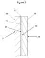
- FIG. 3is a detailed cross-sectional view from the view shown in FIG. 2 ;
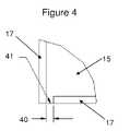
- FIG. 4is a front view of an exemplary embodiment with the front glass removed.
- FIG. 1shows an exemplary display panel 10 , which is comprised of several different layers.
- the cross-section line 2 - 2is shown passing through the center of the display panel 10 .
- the display panel 10is preferably utilized as the exterior portion of a flat panel display assembly.
- Flat panel displaystypically contain several layers. In LCDs for example, there may be several layers which comprise the LCD stack with further layers in front of the stack for the stack for polarizing light or index matching purposes.
- the display panel 10although it is not required to be used as such, would preferably be used as the outer-most layer in the display assembly.
- the detail circlewhich illustrates the detail view shown in FIG. 4 .
- FIG. 2shows a cross-sectional view from the 2 - 2 cross-section shown in FIG. 1 . Due to the scale of the figure it is difficult to discern the individual layers of the display panel 10 . Thus, FIG. 2 contains the details circle which illustrates the detailed view shown in FIG. 3 .
- FIG. 3is a side view of the detail circle in FIG. 2 , which was a cross section through section 2 - 2 of FIG. 1 .
- the various layers of an exemplary embodimentare shown.
- a first layer of glass 15 and a second layer of glass 16comprise the outer layers of the panel.
- Both glass 15 and 16are preferably anti-reflective (AR) glass.
- ARanti-reflective
- Some embodimentsmay have one surface of the glass coated with an AR coating.
- Exemplary embodimentsmay have a pyrolytic surface as the AR coating.
- embodimentsmay have a pyrolytic surface as the outer surface of the panel. Referring to FIG. 3 , an exemplary embodiment would contain a pyrolytic surface on outer surfaces 23 and 21 , where the opposite surfaces 20 and 22 are in contact with the adhesive 18 .
- An exemplary anti-reflective glasscould be Pilkington OptiViewTM glass which is commercially available from Pilkington Building and Specialty Glass Products of Toledo, Ohio (herein ‘OptiView glass’). www.pilkinton.com
- OptiView glassThe document “Pilkington OptiViewTM Anti-Reflective Glass,” Form No. 4483, is herein incorporated by reference in its entirety.
- Chart 1provides typical performance characteristics for two pieces of glass, each with an anti-reflective pyrolytic coating on one side, where the two pieces of glass are laminated or bonded together.
- Pilkington Glassdoes not provide this dual-layered glass with two pyrolytic coatings. Users must purchase single pieces of glass with a single pyrolytic coating and laminate or bond the pieces themselves. See the Chart 1 Notes for specifics.
- Adhesive 18is used to bond the glass layers 15 and 16 .
- An optical adhesiveis preferably used to bond the glass together. Even more preferably, an index-matched optical adhesive may be used.
- Exemplary embodimentsmay utilize Uvecol® S adhesive, commercially available from Cytec Surface Specialties, Inc. of Smyrna, Ga. www.cytec.com. The document “Uvecol® S UV Curable Glass Laminating System,” May 4, 2006, is herein incorporated by reference in its entirety. Embodiments may alternatively utilize Uvecol® A adhesive.
- the glass layers 15 and 16are laminated together by UV-curing the adhesive 18 .
- VHB tape 17may be used to seal around the edges of the glass 15 and 16 .
- the VHB tape 17would be a clear acrylic tape in a thickness between 0.5 mm and 3.0 mm.
- An exemplary display panel for small displaysmay utilize glass panels of thickness between 3.0-3.5 mm and VHB tape of thickness between 0.8-1.2 mm.
- An exemplary display panel for larger displaysmay utilize glass panels of thickness between 6.0-6.5 mm and VHB tape of thickness between 1.0-1.5 mm.
- FIG. 4shows the view of the detailed circle from FIG. 1 where the top piece of glass has been removed.
- the VHB tape 17is shown encircling the edges of glass panel 15 to provide a seal between the two glass panels once assembled.
- a small gap 40may be left open during the assembly process to allow the adhesive to drain from between the glass plates and the surrounding VHB tape seal. Once the excess adhesive has been permitted to drain, the gap 40 may be sealed by a second adhesive material 41 .
- An exemplary second adhesive material 41would be all temperature hot glue. It should be noted that the use of the small gap 40 is not necessary to an embodiment, but may be utilized for the prevention of any defects within the optical adhesive and during the curing of the optical adhesive.
- exemplary display panelscan resist impact from a variety of objects at high speeds. Even when impacted by large objects at high speeds, the display panel may crack, but will not allow the object to penetrate into the display, causing damage to the expensive interior of the display. Further, embodiments resist cracking, but when struck at high speeds the panel may only crack and will not shatter. This shatter-proofing aspect of the embodiments prevents injury to persons who may be be in close proximity to the display when it is impacted.
- the above strength of the panelis accomplished while maintaining a clear panel for viewing an image, preferably a high-definition image. Also, the panel has a low percentage of reflectance, such that other light sources and reflections will not interfere with the viewing of the image produced by the display.
Landscapes
- Physics & Mathematics (AREA)
- Nonlinear Science (AREA)
- Mathematical Physics (AREA)
- Chemical & Material Sciences (AREA)
- Crystallography & Structural Chemistry (AREA)
- General Physics & Mathematics (AREA)
- Optics & Photonics (AREA)
- Devices For Indicating Variable Information By Combining Individual Elements (AREA)
- Surface Treatment Of Optical Elements (AREA)
- Liquid Crystal (AREA)
Abstract
Description
| CHART 1 | |||||
| Solar | |||||
| Heat | |||||
| Nominal | Visible Light | Total Solar Energy | U-Factor | Gain | Shading |
| Glass | Trans- | Reflectance | Reflectance | Trans- | Reflec- | UV Trans- | U.S. | U.S. | Coeffi- | Coeffi- | |
| Thickness | mittance % | % Outside | % Inside | mittance % | tance % | mittance % | Summer* | Winter* | European** | cient | cient |
| ¼ in | 92 | 1.7 | 1.7 | 70 | 3 | <1 | 0.68 | 0.81 | 4.7 | 0.77 | 0.89 |
| ½ in | 89 | 1.6 | 1.6 | 63 | 3 | <1 | 0.65 | 0.77 | 4.5 | 0.72 | 0.83 |
| Notes: | |||||||||||
| ¼″ laminated glass: ⅛″ OptiView™ (#1) + 0.030″ clear pvb with 99% UV absorptance + ⅛″ OptiView ™ (#4) | |||||||||||
| ½″ laminated glass: ¼″ OptiView™ (#1) + 0.030″ clear pvb with 99% UV absorptance + ¼″ OptiView ™ (#4) | |||||||||||
| *Btu/hr · sq ft · ° F. | |||||||||||
| **W/sq m · °K | |||||||||||
Claims (20)
Priority Applications (2)
| Application Number | Priority Date | Filing Date | Title |
|---|---|---|---|
| US12/330,041US8189134B2 (en) | 2008-09-19 | 2008-12-08 | Durable display panel with impact resistance |
| PCT/US2009/067168WO2010077667A2 (en) | 2008-12-08 | 2009-12-08 | Durable display panel with impact resistance |
Applications Claiming Priority (2)
| Application Number | Priority Date | Filing Date | Title |
|---|---|---|---|
| US12/234,182US8711321B2 (en) | 2007-11-16 | 2008-09-19 | System for thermally controlling displays |
| US12/330,041US8189134B2 (en) | 2008-09-19 | 2008-12-08 | Durable display panel with impact resistance |
Related Parent Applications (1)
| Application Number | Title | Priority Date | Filing Date |
|---|---|---|---|
| US12/234,182Continuation-In-PartUS8711321B2 (en) | 2007-11-16 | 2008-09-19 | System for thermally controlling displays |
Publications (2)
| Publication Number | Publication Date |
|---|---|
| US20100075071A1 US20100075071A1 (en) | 2010-03-25 |
| US8189134B2true US8189134B2 (en) | 2012-05-29 |
Family
ID=42310494
Family Applications (1)
| Application Number | Title | Priority Date | Filing Date |
|---|---|---|---|
| US12/330,041Active2030-09-29US8189134B2 (en) | 2008-09-19 | 2008-12-08 | Durable display panel with impact resistance |
Country Status (2)
| Country | Link |
|---|---|
| US (1) | US8189134B2 (en) |
| WO (1) | WO2010077667A2 (en) |
Cited By (11)
| Publication number | Priority date | Publication date | Assignee | Title |
|---|---|---|---|---|
| US9451060B1 (en) | 2015-10-15 | 2016-09-20 | Civiq Smartscapes, Llc | Techniques and apparatus for controlling access to components of a personal communication structure (PCS) |
| US9516485B1 (en) | 2015-11-13 | 2016-12-06 | Civiq Smartscapes, Llc | Systems and methods for making emergency phone calls |
| US9622392B1 (en) | 2015-09-17 | 2017-04-11 | Civiq Smartscapes, Llc | Techniques and apparatus for controlling the temperature of a personal communication structure (PCS) |
| US9703320B2 (en) | 2015-09-17 | 2017-07-11 | Civiq Smartscapes, Llc | Techniques and apparatus for mounting a housing on a personal communication structure (PCS) |
| US9823690B2 (en) | 2015-09-11 | 2017-11-21 | Civiq Smartscapes, Llc | Techniques and apparatus for securing a structure to a support |
| US10127781B2 (en) | 2015-11-16 | 2018-11-13 | Civiq Smartscapes, Llc | Systems and techniques for vandalism detection in a personal communication structure (PCS) |
| US10270918B2 (en) | 2015-10-15 | 2019-04-23 | Civiq Smartscapes, Llc | Method and apparatus for power and temperature control of compartments within a personal communication structure (PCS) |
| US11402940B2 (en) | 2019-02-25 | 2022-08-02 | Manufacturing Resources International, Inc. | Monitoring the status of a touchscreen |
| US12207437B2 (en) | 2008-03-03 | 2025-01-21 | Manufacturing Resources International, Inc. | Electronic display with cooling |
| US12298614B2 (en) | 2020-03-27 | 2025-05-13 | Manufacturing Resources International, Inc. | Display unit with monitoring features |
| US12373153B2 (en) | 2023-10-04 | 2025-07-29 | Manufacturing Resources International, Inc. | Display unit with vandalism deterrence features |
Families Citing this family (1)
| Publication number | Priority date | Publication date | Assignee | Title |
|---|---|---|---|---|
| US9500872B2 (en) | 2012-11-30 | 2016-11-22 | Corning Incorporated | Glass encapsulated polymeric lenticular system for autostereoscopic display |
Citations (12)
| Publication number | Priority date | Publication date | Assignee | Title |
|---|---|---|---|---|
| US4715686A (en)* | 1984-11-16 | 1987-12-29 | Seiko Epson Corporation | Light-passive display device and method of manufacturing same |
| US5606438A (en)* | 1994-06-11 | 1997-02-25 | Motorola, Inc. | Rugged liquid crystal display and method of manufacture |
| US5835179A (en)* | 1996-08-30 | 1998-11-10 | Sony Corporation | Liquid crystal display |
| US6219127B1 (en)* | 1998-01-12 | 2001-04-17 | Semiconductor Energy Laboratory Co., Ltd. | Display device |
| US6392727B1 (en) | 1998-12-31 | 2002-05-21 | Honeywell International Inc. | Reduced reflectance polarized display |
| US6472032B1 (en) | 1998-03-17 | 2002-10-29 | Nippon Sheet Glass Co., Ltd. | Double-glazing unit |
| WO2004036270A1 (en) | 2002-10-14 | 2004-04-29 | 3M Innovative Properties Company | Antireflection films for use with displays |
| US6731367B1 (en)* | 1998-12-04 | 2004-05-04 | Seiko Epson Corporation | Electro-optical panel, electro-optical panel module, and projection display device |
| JP2005055641A (en) | 2003-08-04 | 2005-03-03 | Yokogawa Electric Corp | Liquid crystal display |
| US6909486B2 (en) | 2003-02-18 | 2005-06-21 | Ran-Hong Raymond Wang | Liquid crystal display viewable under all lighting conditions |
| US6955833B1 (en) | 1998-12-01 | 2005-10-18 | Pilkington Plc | Coating glass |
| US20100296027A1 (en)* | 2006-10-17 | 2010-11-25 | Tsutomu Matsuhira | Display device |
Family Cites Families (2)
| Publication number | Priority date | Publication date | Assignee | Title |
|---|---|---|---|---|
| JPH08271883A (en)* | 1995-03-31 | 1996-10-18 | Sekisui Chem Co Ltd | Glass cell laminated body for liquid crystal display |
| US7463734B2 (en)* | 2006-02-03 | 2008-12-09 | Sony Ericsson Mobile Communications Ab | Display window cover assemblies and electronic devices and methods using the same |
- 2008
- 2008-12-08USUS12/330,041patent/US8189134B2/enactiveActive
- 2009
- 2009-12-08WOPCT/US2009/067168patent/WO2010077667A2/enactiveApplication Filing
Patent Citations (14)
| Publication number | Priority date | Publication date | Assignee | Title |
|---|---|---|---|---|
| US4715686A (en)* | 1984-11-16 | 1987-12-29 | Seiko Epson Corporation | Light-passive display device and method of manufacturing same |
| US5606438A (en)* | 1994-06-11 | 1997-02-25 | Motorola, Inc. | Rugged liquid crystal display and method of manufacture |
| US5835179A (en)* | 1996-08-30 | 1998-11-10 | Sony Corporation | Liquid crystal display |
| US6219127B1 (en)* | 1998-01-12 | 2001-04-17 | Semiconductor Energy Laboratory Co., Ltd. | Display device |
| US7283185B2 (en)* | 1998-01-12 | 2007-10-16 | Semiconductor Energy Laboratory Co., Ltd. | Display device |
| US6472032B1 (en) | 1998-03-17 | 2002-10-29 | Nippon Sheet Glass Co., Ltd. | Double-glazing unit |
| US6955833B1 (en) | 1998-12-01 | 2005-10-18 | Pilkington Plc | Coating glass |
| US6731367B1 (en)* | 1998-12-04 | 2004-05-04 | Seiko Epson Corporation | Electro-optical panel, electro-optical panel module, and projection display device |
| US6392727B1 (en) | 1998-12-31 | 2002-05-21 | Honeywell International Inc. | Reduced reflectance polarized display |
| WO2004036270A1 (en) | 2002-10-14 | 2004-04-29 | 3M Innovative Properties Company | Antireflection films for use with displays |
| US6909486B2 (en) | 2003-02-18 | 2005-06-21 | Ran-Hong Raymond Wang | Liquid crystal display viewable under all lighting conditions |
| US6961108B2 (en) | 2003-02-18 | 2005-11-01 | Ran-Hong Raymond Wang | Liquid crystal display viewable under all lighting conditions |
| JP2005055641A (en) | 2003-08-04 | 2005-03-03 | Yokogawa Electric Corp | Liquid crystal display |
| US20100296027A1 (en)* | 2006-10-17 | 2010-11-25 | Tsutomu Matsuhira | Display device |
Non-Patent Citations (2)
| Title |
|---|
| Pilkington Building Products North America, Pilkington OptiView Anti-Reflective Glass, product spec sheet, 2005. |
| SYTEC Surface Specialties Inc., Uvekol S UV Curable Glass Laminating System, product spec sheet, May 4, 2006. |
Cited By (16)
| Publication number | Priority date | Publication date | Assignee | Title |
|---|---|---|---|---|
| US12207437B2 (en) | 2008-03-03 | 2025-01-21 | Manufacturing Resources International, Inc. | Electronic display with cooling |
| US12274022B2 (en) | 2008-03-03 | 2025-04-08 | Manufacturing Resources International, Inc. | Electronic display with cooling |
| US9823690B2 (en) | 2015-09-11 | 2017-11-21 | Civiq Smartscapes, Llc | Techniques and apparatus for securing a structure to a support |
| US9622392B1 (en) | 2015-09-17 | 2017-04-11 | Civiq Smartscapes, Llc | Techniques and apparatus for controlling the temperature of a personal communication structure (PCS) |
| US9703320B2 (en) | 2015-09-17 | 2017-07-11 | Civiq Smartscapes, Llc | Techniques and apparatus for mounting a housing on a personal communication structure (PCS) |
| US9451060B1 (en) | 2015-10-15 | 2016-09-20 | Civiq Smartscapes, Llc | Techniques and apparatus for controlling access to components of a personal communication structure (PCS) |
| US10051097B2 (en) | 2015-10-15 | 2018-08-14 | Civiq Smartscapes, Llc | Techniques and apparatus for controlling access to components of a personal communication structure (PCS) |
| US10270918B2 (en) | 2015-10-15 | 2019-04-23 | Civiq Smartscapes, Llc | Method and apparatus for power and temperature control of compartments within a personal communication structure (PCS) |
| US9516485B1 (en) | 2015-11-13 | 2016-12-06 | Civiq Smartscapes, Llc | Systems and methods for making emergency phone calls |
| US10127781B2 (en) | 2015-11-16 | 2018-11-13 | Civiq Smartscapes, Llc | Systems and techniques for vandalism detection in a personal communication structure (PCS) |
| US12175035B2 (en) | 2019-02-25 | 2024-12-24 | Manufacturing Resources International, Inc. | Monitoring the status of a touchscreen |
| US11644921B2 (en) | 2019-02-25 | 2023-05-09 | Manufacturing Resources International, Inc. | Monitoring the status of a touchscreen |
| US11402940B2 (en) | 2019-02-25 | 2022-08-02 | Manufacturing Resources International, Inc. | Monitoring the status of a touchscreen |
| US12298614B2 (en) | 2020-03-27 | 2025-05-13 | Manufacturing Resources International, Inc. | Display unit with monitoring features |
| US12326626B2 (en) | 2020-03-27 | 2025-06-10 | Manufacturing Resources International, Inc. | Display unit with monitoring features |
| US12373153B2 (en) | 2023-10-04 | 2025-07-29 | Manufacturing Resources International, Inc. | Display unit with vandalism deterrence features |
Also Published As
| Publication number | Publication date |
|---|---|
| US20100075071A1 (en) | 2010-03-25 |
| WO2010077667A3 (en) | 2010-09-16 |
| WO2010077667A2 (en) | 2010-07-08 |
Similar Documents
| Publication | Publication Date | Title |
|---|---|---|
| US8189134B2 (en) | Durable display panel with impact resistance | |
| US20220072827A1 (en) | Glass laminated articles and layered articles | |
| US9946147B2 (en) | Transmission-type transparent screen, image display system and image display method | |
| EP2531687B1 (en) | Multiple flashing glass panels having light-emitting diodes | |
| US8711321B2 (en) | System for thermally controlling displays | |
| US20140313452A1 (en) | Glass Assembly on Monitor Array | |
| CN100570406C (en) | Safety glass protective screen for liquid crystal display and liquid crystal display using the same | |
| CN104395071A (en) | Glass resin laminate | |
| AU2015359391A1 (en) | Insulating window unit | |
| AU2010319888A1 (en) | Field serviceable electronic display | |
| CN105074551A (en) | Switchable projection panel | |
| WO2015025963A1 (en) | Heat ray shielding material | |
| CN107000387B (en) | Laminates of thick polymer material sheets and thin glass sheets | |
| JP6287533B2 (en) | Heat-shielding laminated glass | |
| TWI698842B (en) | Building material glass plate with display device and building material glass structure | |
| US20120275017A1 (en) | Energy conservation assembly and method for using the same | |
| CN206774561U (en) | A kind of light-duty hard photovoltaic panel | |
| CN114051452B (en) | Laminated glass | |
| KR20070000216U (en) | Transparent soundproof wall material incorporating various information markers | |
| CN211577608U (en) | Glass panel structure for display screen | |
| CN201035269Y (en) | nonscatterable glass protection screen for LCD and LCD using the same | |
| CN110481045B (en) | Weight-reduced transparent display touch screen bonding structure and manufacturing method thereof | |
| CN109545096A (en) | Outdoor advertisement machine | |
| TWI898368B (en) | Tiling film and tiled display | |
| America | Architectural Glass Product Guide |
Legal Events
| Date | Code | Title | Description |
|---|---|---|---|
| AS | Assignment | Owner name:MANUFACTURING RESOURCES INTERNATIONAL, INC.,GEORGI Free format text:ASSIGNMENT OF ASSIGNORS INTEREST;ASSIGNOR:LECAVE, MICHAEL;REEL/FRAME:022058/0212 Effective date:20081216 Owner name:MANUFACTURING RESOURCES INTERNATIONAL, INC., GEORG Free format text:ASSIGNMENT OF ASSIGNORS INTEREST;ASSIGNOR:LECAVE, MICHAEL;REEL/FRAME:022058/0212 Effective date:20081216 | |
| AS | Assignment | Owner name:BANK OF AMERICA, N.A., GEORGIA Free format text:SECURITY AGREEMENT;ASSIGNOR:MANUFACTURING RESOURCES INTERNATIONAL, INC.;REEL/FRAME:027175/0973 Effective date:20111020 | |
| STCF | Information on status: patent grant | Free format text:PATENTED CASE | |
| FPAY | Fee payment | Year of fee payment:4 | |
| AS | Assignment | Owner name:MANUFACTURING RESOURCES INTERNATIONAL, INC, GEORGIA Free format text:RELEASE BY SECURED PARTY;ASSIGNOR:BANK OF AMERICA, N.A., AS ADMINISTRATIVE AGENT;REEL/FRAME:047227/0329 Effective date:20180605 Owner name:MANUFACTURING RESOURCES INTERNATIONAL, INC, GEORGI Free format text:RELEASE BY SECURED PARTY;ASSIGNOR:BANK OF AMERICA, N.A., AS ADMINISTRATIVE AGENT;REEL/FRAME:047227/0329 Effective date:20180605 | |
| AS | Assignment | Owner name:MANUFACTURING RESOURCES INTERNATIONAL, INC, GEORGIA Free format text:RELEASE BY SECURED PARTY;ASSIGNOR:FIFTH THIRD BANK;REEL/FRAME:046924/0379 Effective date:20180612 Owner name:MANUFACTURING RESOURCES INTERNATIONAL, INC, GEORGI Free format text:RELEASE BY SECURED PARTY;ASSIGNOR:FIFTH THIRD BANK;REEL/FRAME:046924/0379 Effective date:20180612 | |
| MAFP | Maintenance fee payment | Free format text:PAYMENT OF MAINTENANCE FEE, 8TH YEAR, LARGE ENTITY (ORIGINAL EVENT CODE: M1552); ENTITY STATUS OF PATENT OWNER: LARGE ENTITY Year of fee payment:8 | |
| MAFP | Maintenance fee payment | Free format text:PAYMENT OF MAINTENANCE FEE, 12TH YEAR, LARGE ENTITY (ORIGINAL EVENT CODE: M1553); ENTITY STATUS OF PATENT OWNER: LARGE ENTITY Year of fee payment:12 |