US8188878B2 - LED light communication system - Google Patents
LED light communication systemDownload PDFInfo
- Publication number
- US8188878B2 US8188878B2US12/126,529US12652908AUS8188878B2US 8188878 B2US8188878 B2US 8188878B2US 12652908 AUS12652908 AUS 12652908AUS 8188878 B2US8188878 B2US 8188878B2
- Authority
- US
- United States
- Prior art keywords
- light
- led
- communication
- signal
- optical
- Prior art date
- Legal status (The legal status is an assumption and is not a legal conclusion. Google has not performed a legal analysis and makes no representation as to the accuracy of the status listed.)
- Expired - Lifetime, expires
Links
Images


Classifications
- G—PHYSICS
- G07—CHECKING-DEVICES
- G07C—TIME OR ATTENDANCE REGISTERS; REGISTERING OR INDICATING THE WORKING OF MACHINES; GENERATING RANDOM NUMBERS; VOTING OR LOTTERY APPARATUS; ARRANGEMENTS, SYSTEMS OR APPARATUS FOR CHECKING NOT PROVIDED FOR ELSEWHERE
- G07C9/00—Individual registration on entry or exit
- G07C9/30—Individual registration on entry or exit not involving the use of a pass
- G07C9/32—Individual registration on entry or exit not involving the use of a pass in combination with an identity check
- G07C9/37—Individual registration on entry or exit not involving the use of a pass in combination with an identity check using biometric data, e.g. fingerprints, iris scans or voice recognition
- G—PHYSICS
- G08—SIGNALLING
- G08B—SIGNALLING OR CALLING SYSTEMS; ORDER TELEGRAPHS; ALARM SYSTEMS
- G08B13/00—Burglar, theft or intruder alarms
- G08B13/18—Actuation by interference with heat, light, or radiation of shorter wavelength; Actuation by intruding sources of heat, light, or radiation of shorter wavelength
- G08B13/189—Actuation by interference with heat, light, or radiation of shorter wavelength; Actuation by intruding sources of heat, light, or radiation of shorter wavelength using passive radiation detection systems
- G08B13/194—Actuation by interference with heat, light, or radiation of shorter wavelength; Actuation by intruding sources of heat, light, or radiation of shorter wavelength using passive radiation detection systems using image scanning and comparing systems
- G08B13/196—Actuation by interference with heat, light, or radiation of shorter wavelength; Actuation by intruding sources of heat, light, or radiation of shorter wavelength using passive radiation detection systems using image scanning and comparing systems using television cameras
- G08B13/19602—Image analysis to detect motion of the intruder, e.g. by frame subtraction
- G08B13/19613—Recognition of a predetermined image pattern or behaviour pattern indicating theft or intrusion
- G—PHYSICS
- G08—SIGNALLING
- G08B—SIGNALLING OR CALLING SYSTEMS; ORDER TELEGRAPHS; ALARM SYSTEMS
- G08B13/00—Burglar, theft or intruder alarms
- G08B13/18—Actuation by interference with heat, light, or radiation of shorter wavelength; Actuation by intruding sources of heat, light, or radiation of shorter wavelength
- G08B13/189—Actuation by interference with heat, light, or radiation of shorter wavelength; Actuation by intruding sources of heat, light, or radiation of shorter wavelength using passive radiation detection systems
- G08B13/194—Actuation by interference with heat, light, or radiation of shorter wavelength; Actuation by intruding sources of heat, light, or radiation of shorter wavelength using passive radiation detection systems using image scanning and comparing systems
- G08B13/196—Actuation by interference with heat, light, or radiation of shorter wavelength; Actuation by intruding sources of heat, light, or radiation of shorter wavelength using passive radiation detection systems using image scanning and comparing systems using television cameras
- G08B13/19639—Details of the system layout
- G08B13/19645—Multiple cameras, each having view on one of a plurality of scenes, e.g. multiple cameras for multi-room surveillance or for tracking an object by view hand-over
- G—PHYSICS
- G08—SIGNALLING
- G08B—SIGNALLING OR CALLING SYSTEMS; ORDER TELEGRAPHS; ALARM SYSTEMS
- G08B13/00—Burglar, theft or intruder alarms
- G08B13/18—Actuation by interference with heat, light, or radiation of shorter wavelength; Actuation by intruding sources of heat, light, or radiation of shorter wavelength
- G08B13/189—Actuation by interference with heat, light, or radiation of shorter wavelength; Actuation by intruding sources of heat, light, or radiation of shorter wavelength using passive radiation detection systems
- G08B13/194—Actuation by interference with heat, light, or radiation of shorter wavelength; Actuation by intruding sources of heat, light, or radiation of shorter wavelength using passive radiation detection systems using image scanning and comparing systems
- G08B13/196—Actuation by interference with heat, light, or radiation of shorter wavelength; Actuation by intruding sources of heat, light, or radiation of shorter wavelength using passive radiation detection systems using image scanning and comparing systems using television cameras
- G08B13/19639—Details of the system layout
- G08B13/19647—Systems specially adapted for intrusion detection in or around a vehicle
- G—PHYSICS
- G08—SIGNALLING
- G08B—SIGNALLING OR CALLING SYSTEMS; ORDER TELEGRAPHS; ALARM SYSTEMS
- G08B13/00—Burglar, theft or intruder alarms
- G08B13/18—Actuation by interference with heat, light, or radiation of shorter wavelength; Actuation by intruding sources of heat, light, or radiation of shorter wavelength
- G08B13/189—Actuation by interference with heat, light, or radiation of shorter wavelength; Actuation by intruding sources of heat, light, or radiation of shorter wavelength using passive radiation detection systems
- G08B13/194—Actuation by interference with heat, light, or radiation of shorter wavelength; Actuation by intruding sources of heat, light, or radiation of shorter wavelength using passive radiation detection systems using image scanning and comparing systems
- G08B13/196—Actuation by interference with heat, light, or radiation of shorter wavelength; Actuation by intruding sources of heat, light, or radiation of shorter wavelength using passive radiation detection systems using image scanning and comparing systems using television cameras
- G08B13/19639—Details of the system layout
- G08B13/19652—Systems using zones in a single scene defined for different treatment, e.g. outer zone gives pre-alarm, inner zone gives alarm
- G—PHYSICS
- G08—SIGNALLING
- G08B—SIGNALLING OR CALLING SYSTEMS; ORDER TELEGRAPHS; ALARM SYSTEMS
- G08B13/00—Burglar, theft or intruder alarms
- G08B13/18—Actuation by interference with heat, light, or radiation of shorter wavelength; Actuation by intruding sources of heat, light, or radiation of shorter wavelength
- G08B13/189—Actuation by interference with heat, light, or radiation of shorter wavelength; Actuation by intruding sources of heat, light, or radiation of shorter wavelength using passive radiation detection systems
- G08B13/194—Actuation by interference with heat, light, or radiation of shorter wavelength; Actuation by intruding sources of heat, light, or radiation of shorter wavelength using passive radiation detection systems using image scanning and comparing systems
- G08B13/196—Actuation by interference with heat, light, or radiation of shorter wavelength; Actuation by intruding sources of heat, light, or radiation of shorter wavelength using passive radiation detection systems using image scanning and comparing systems using television cameras
- G08B13/19663—Surveillance related processing done local to the camera
- G—PHYSICS
- G08—SIGNALLING
- G08B—SIGNALLING OR CALLING SYSTEMS; ORDER TELEGRAPHS; ALARM SYSTEMS
- G08B13/00—Burglar, theft or intruder alarms
- G08B13/18—Actuation by interference with heat, light, or radiation of shorter wavelength; Actuation by intruding sources of heat, light, or radiation of shorter wavelength
- G08B13/189—Actuation by interference with heat, light, or radiation of shorter wavelength; Actuation by intruding sources of heat, light, or radiation of shorter wavelength using passive radiation detection systems
- G08B13/194—Actuation by interference with heat, light, or radiation of shorter wavelength; Actuation by intruding sources of heat, light, or radiation of shorter wavelength using passive radiation detection systems using image scanning and comparing systems
- G08B13/196—Actuation by interference with heat, light, or radiation of shorter wavelength; Actuation by intruding sources of heat, light, or radiation of shorter wavelength using passive radiation detection systems using image scanning and comparing systems using television cameras
- G08B13/19665—Details related to the storage of video surveillance data
- G08B13/19671—Addition of non-video data, i.e. metadata, to video stream
- G—PHYSICS
- G08—SIGNALLING
- G08B—SIGNALLING OR CALLING SYSTEMS; ORDER TELEGRAPHS; ALARM SYSTEMS
- G08B31/00—Predictive alarm systems characterised by extrapolation or other computation using updated historic data
- H—ELECTRICITY
- H04—ELECTRIC COMMUNICATION TECHNIQUE
- H04B—TRANSMISSION
- H04B10/00—Transmission systems employing electromagnetic waves other than radio-waves, e.g. infrared, visible or ultraviolet light, or employing corpuscular radiation, e.g. quantum communication
- H04B10/11—Arrangements specific to free-space transmission, i.e. transmission through air or vacuum
- H04B10/114—Indoor or close-range type systems
- H04B10/116—Visible light communication
- H—ELECTRICITY
- H04—ELECTRIC COMMUNICATION TECHNIQUE
- H04B—TRANSMISSION
- H04B10/00—Transmission systems employing electromagnetic waves other than radio-waves, e.g. infrared, visible or ultraviolet light, or employing corpuscular radiation, e.g. quantum communication
- H04B10/40—Transceivers
- H—ELECTRICITY
- H04—ELECTRIC COMMUNICATION TECHNIQUE
- H04B—TRANSMISSION
- H04B3/00—Line transmission systems
- H04B3/54—Systems for transmission via power distribution lines
- H—ELECTRICITY
- H04—ELECTRIC COMMUNICATION TECHNIQUE
- H04W—WIRELESS COMMUNICATION NETWORKS
- H04W4/00—Services specially adapted for wireless communication networks; Facilities therefor
- H04W4/02—Services making use of location information
- H04W4/025—Services making use of location information using location based information parameters
- H—ELECTRICITY
- H05—ELECTRIC TECHNIQUES NOT OTHERWISE PROVIDED FOR
- H05B—ELECTRIC HEATING; ELECTRIC LIGHT SOURCES NOT OTHERWISE PROVIDED FOR; CIRCUIT ARRANGEMENTS FOR ELECTRIC LIGHT SOURCES, IN GENERAL
- H05B47/00—Circuit arrangements for operating light sources in general, i.e. where the type of light source is not relevant
- H05B47/10—Controlling the light source
- H05B47/175—Controlling the light source by remote control
- H05B47/185—Controlling the light source by remote control via power line carrier transmission
- H—ELECTRICITY
- H05—ELECTRIC TECHNIQUES NOT OTHERWISE PROVIDED FOR
- H05B—ELECTRIC HEATING; ELECTRIC LIGHT SOURCES NOT OTHERWISE PROVIDED FOR; CIRCUIT ARRANGEMENTS FOR ELECTRIC LIGHT SOURCES, IN GENERAL
- H05B47/00—Circuit arrangements for operating light sources in general, i.e. where the type of light source is not relevant
- H05B47/10—Controlling the light source
- H05B47/175—Controlling the light source by remote control
- H05B47/19—Controlling the light source by remote control via wireless transmission
- H05B47/195—Controlling the light source by remote control via wireless transmission the transmission using visible or infrared light
Definitions
- the present inventionis generally directed to light emitting diodes (LEDs) and applications thereof.
- LEDslight emitting diodes
- some embodiments of the present inventionare directed to using LEDs and power line communication technology to provide internet access and communication capability to residential and commercial clientele.
- RFradiofrequency
- light sources used for communicationare extremely secure due to the fact that they are focused within a narrow beam, requiring placing equipment within the beam itself for interception. Also, because the visible spectrum is not regulated by the FCC, light sources can be used for communications purposes without the need of a license. And, light sources are not susceptible to interference nor do they produce noise that can interfere with other devices.
- LEDsLight emitting diodes
- LEDscan be used as light sources for data transmission, as described in U.S. Pat. Nos. 6,879,263 and 7,046,160, the entire contents of each being expressly incorporated herein by reference.
- LEDshave quick response to “ON” and “OFF” signals, as compared to the longer warm-up and response times associated with fluorescent lighting, for example.
- LEDsare also efficient in producing light, as measured in lumens per watt.
- Recent developments in LED technology, such as high brightness blue LEDs, which in turn paved the way for white LEDshave made LEDs a practical alternative to conventional light sources. As such, LED technology provides a practical opportunity to combine lighting and communication. This combination of lighting and communication allows ubiquitous light sources such as street lights, home lighting, and office building lighting, for example, to be converted to, or supplemented with, LED technology to provide for communications while simultaneously producing light for illumination purposes.
- building managementis a complex science which incorporates and governs all facets of human, mechanical and structural systems associated with buildings.
- most commercial buildingsare managed by commercial property management companies with great expertise.
- the interrelationships between people and the mechanical and structural systemsare most desirably evaluated.
- human interactions with a building and associated mechanical systemswill be optimized, in turn providing the greatest benefit to both the owners and those who use the facilities afforded by the building.
- building usersmay include both regular occupants such as individual or commercial tenants, and also transient occupants such as visitors, guests, or commercial customers.
- Building managementincludes diverse facets, some which are simply representations of the building and associated systems and people, and other facets which are tangible. Exemplary of representations are accounting or financial monitoring responsibilities which will including record keeping control and assurance of financial transactions involving tenants, owners, and service providers. Exemplary of the physical or tangible responsibilities are physical development and maintenance, including identification of need for features, improvements, maintenance and the assurance of the execution of the same. As is well understood by those highly versed in building management, the diverse responsibilities and extent of information required to manage a building is often quite overwhelming.
- a supply closetwill not ordinarily be designed for around-the-clock illumination, and may instead by configured to operate on a switch, or alternatively a motion detector with relatively short-delay turn-off when no motion is detected.
- a switchor alternatively a motion detector with relatively short-delay turn-off when no motion is detected.
- the use of appropriate switches and motion detectorshelps to reduce the energy required for a building to function with occupants, and simultaneously increases the life of many illumination components such as light sources (light bulbs and equivalents thereto) since the light sources are only required intermittently.
- a room where movies, slides, computer or other visual or audio-visual presentations are givensuch as a boardroom or classroom
- This minimum level of illuminationenables occupants sufficient light for note-taking, safe movement and other important activities, without interfering with the legibility of a presentation.
- a primary work-spacesuch as a desk or kitchen counter will require illumination that does not cast shadows on the work space while work is being performed. Complementary illumination, such as windows or skylights, is also important in design consideration.
- LED bulbthat may be most appropriate for a space or location.
- Original electric light bulbswere incandescent. With sufficient electrical energy, which is converted to heat within an incandescent bulb filament, the filament will emit visible light. This is similar to a fire, where with enough heat, visible light is produced.
- incandescent bulbsproduce far more heat than light. The color of the light from these bulbs is also most commonly quite yellow, casting a warm hue at a color temperature typically in the vicinity of 3,000 degrees Kelvin. Warm hues are often prized in relaxed settings such as those of a living room or dining room, more closely resembling gentle candle light.
- a fluorescent light bulbuses a small amount of mercury in vapor state. High voltage electricity is applied to the mercury gas, causing the gas to ionize and generate some visible light, but primarily UltraViolet (UV) light. UV light is harmful to humans, being the component that causes sun burns, so the UV component of the light must be converted into visible light.
- UV lightis harmful to humans, being the component that causes sun burns, so the UV component of the light must be converted into visible light.
- the inside of a fluorescent tubeis coated with a phosphorescent material, which when exposed to ultraviolet light glows in the visible spectrum. This is similar to many glow-in-the-dark toys and other devices that incorporate phosphorescent materials.
- the illumination from a fluorescent lightwill continue for a significant time, even after electrical power is discontinued, which for the purposes of the present disclosure will be understood to be the latent period or latency between the change in power status and response by the phosphor.
- the efficiencies and brightness of the phosphorshas improved, so in many instances have the delays in illumination and extinguishing, or latency, increased.
- fluorescent bulbsmay be manufactured that produce light from different parts of the spectrum, resulting in manufacturing control of the color temperature, or hue or warmness of a bulb.
- fluorescent bulbsEven though quite widespread, is controversial for several reasons.
- PCBsPolychlorinated BiPhenyls
- fluorescent bulbsEven if modern ballasts are used, fluorescent bulbs also contain a small but finite amount of mercury. Even very small amounts of mercury are sufficient to contaminate a property. Consequently, both the manufacture and disposal of mercury-containing fluorescent tubes is hazardous.
- Fluorescent lightinghas also been alleged to cause chemical reactions in the brain and body that produce fatigue, depression, immuno-suppression, and reduced metabolism. Further, while the phosphor materials may be selected to provide hue or color control, this hue is fixed at the time of manufacture, and so is not easily changed to meet changing or differing needs for a given building space.
- Halide, mercury and sodium vapor lampsoperate at higher temperatures and pressures, and so present undesirably greater fire hazards. In addition, these bulbs present a possibility of exposure to harmful radiation from undetected ruptured outer bulbs. Furthermore, mercury and sodium vapor lamps generally have very poor color-rendition-indices, meaning the light rendered by these bulbs is quite different from ordinary daylight, distorting human color perception. Yet another set of disadvantages has to do with the starting or lighting of these types of bulbs. Mercury and sodium vapor lamps both exhibit extremely slow starting times, often measured by many minutes. The in-rush currents during starting are also commonly large.
- ballastschange dimension due to magnetostrictive forces. Magnetic field leakage from the ballast may undesirably couple to adjacent conductive or ferromagnetic materials, resulting in magnetic forces as well. Both types of forces will generate undesirable sound. Additionally, in some cases a less-optimal bulb may also produce a buzzing sound.
- a second very important area associated with building managementis energy management.
- the concern for energy managementis driven by the expense associated with energy consumed over the life of a building.
- Energy managementis quite challenging to design into a building, because many human variables come into play within different areas within a building structure. Considering the foregoing discussion of lighting, different occupants will have different preferences and habits. Some occupants may regularly forget to turn off lights when a space is no longer being occupied, thereby wasting electricity and diminishing the useful life of the light bulbs. In another instance, one occupant may require full illumination for that occupant to operate efficiently or safely within a space, while a second occupant might only require a small amount or local area of illumination. Further complicating the matter of energy management is the fact that many commercial establishments may have rates based upon peak usage.
- a business with a large number of lights that are controlled with a common switchmay have peak demands large relative to total consumption of power, simply due to the relatively large amount of power that will rush in to the circuit. Breaking the circuit into several switches may not adequately address inrush current, since a user may switch more than one switch at a time, such as by sliding a hand across several switches at once. Additionally, during momentary or short-term power outages, the start-up of electrical devices by the power company is known to cause many problems, sometimes harming either customer equipment or power company devices. Control over inrush current is therefore very desirable, and not economically viable in the prior art.
- Energy managementalso includes consideration for differences in temperature preferred by different occupants or for different activities.
- an occupant of a first office space within a buildingmay prefer a temperature close to 68 degrees Fahrenheit, while a different occupant in a second office space may prefer a temperature close to 78 degrees Fahrenheit.
- the first and second office spacesmay even be the same office space, just at different times of day.
- an employee working in a mail room from 8 a.m. until 4 p.m.may be replaced by a different mail room employee who works from 4 p.m. until 12 a.m.
- HVACHeating, Ventilation, and Air Conditioning
- a third very important area associated with building managementis security.
- a schoolas but one example of a public building, a one-room country school fifty years ago was made up of one teacher who knew well the small number of pupils.
- Securityconsisted of a simple padlock on a wooden door. The several windows on one side of the room provided light. They were locked but almost never broken into, for nothing of major value, even during the Depression, enticed potential thieves.
- one or more guardsmay check identification, admission badges or paperwork, while one or more other guards monitor metal detectors.
- One or more additional guardsmay be monitoring drug sniffing dogs or equipment, or spot checking bags.
- motion sensors and other prior art electronic security measuresWhile often beneficial, occasionally fail even when used in combination with security personnel to provide adequate protection.
- motion sensorsmay be activated by strong winds, stray animals, passing vehicles, or blowing debris. Inside, they operate only for a specific time; a room's occupant, if not moving about, may suddenly be in the dark and must re-activate the light by waving or flailing about.
- LEDscan be used in networking applications.
- a variety of client deviceswill communicate with one or more host devices.
- the hostmay provide connection to a Local Area Network (LAN), sometimes referred to as an Intranet, owing to the common use of such a network entirely within an office space, building, or business.
- the hostmay additionally or alternatively provide connection to a Wide Area Network (WAN), commonly describing a network coupling widely separated physical locations which are connected together through any suitable connection, including for exemplary purposes but not solely limited thereto such means as fiber optic links, T1 lines, Radio Frequency (RF) links including cellular telecommunications links, satellite connections, DSL connections, or even Internet connections.
- WANWide Area Network
- RFRadio Frequency
- client deviceshave heretofore been enabled to connect to host devices.
- client devicesmay commonly include computing devices of all sorts, ranging from hand-held devices such as Personal Digital Assistants (PDAs) to massive mainframe computers, and including Personal Computers (PCs).
- PDAsPersonal Digital Assistants
- PCsPersonal Computers
- client devicesmay also include printers, network storage devices, cameras, other security and safety devices, appliances, HVAC systems, manufacturing machinery, and so forth.
- any devicewhich incorporates or can be made to incorporate sufficient electronic circuitry may be so linked as a client to a host.
- Existing client devicesare designed to connect to host network access points through wired connections, like copper wire, for example, fiber optic connections, or as wireless connections, such as wireless routers.
- wired connectionslike copper wire, for example, fiber optic connections, or as wireless connections, such as wireless routers.
- the host and clientare tethered together through this physical communications channel.
- the tetherlimits movement of the client relative to the host, is often unsightly and hard to contain in a workspace, and so may even be or become a tripping hazard.
- electrical connectorssuch as jacks must be provided, and these connectors necessarily limit the number of access points and locations. The installation of connectors defaces walls, sometimes rendering them unsuitable for a particular desired application, and yet they add undesirable installation expense, whether during new construction or in retrofitting an existing building structure.
- an RF signalreplaces the physical communications channel with a radio channel.
- client devices in a wireless systemtry through various broadcasts and signal receptions to find an access point that will have adequate transmission and reception, generally within a certain signal range which may range from a few meters to as many as several tens of meters.
- the systemsare programmed to bridge from a host access point to various client devices through known exchanges of information, commonly described as communications protocols or handshakes.
- client connection devicessuch as PCMCIA or PC cards, serial ports, parallel ports, SIMM cards, USB connectors, Ethernet cards or connectors, firewire interfaces, Bluetooth compatible devices, infrared/IrDA devices, and other known or similar components.
- Buildingscan encompass a very large number of rooms or discrete spaces, each functioning relatively independently from each other. Where the rooms or discrete spaces together form a larger entity such as a business, public institution or facility, or the like, which have attempted to include synchronized time keeping throughout the entity. A large number of buildings, both public and private, have synchronized clocks installed therein.
- a buildingmay accommodate very different numbers of occupants at different times within a relatively enclosed space, such as a meeting or class room.
- the number of occupantsis known to significantly alter the temperature and associated need for HVAC control.
- other factorssuch as weather conditions and sunlight or lack thereof through windows in a room may have as much or greater effect on the need for HVAC control.
- many older buildingswere only provided with a single central thermostat, providing the same amount of heating or air conditioning to a room or other space regardless of demand for the same.
- Newer HVAC systemsenable control, through electrically controlled dampers or vents within the HVAC system to much more precisely respond to the needs of a single space or room within a building.
- the roommay not be individually controlled.
- More buildingsare incorporating wireless networks within the building, the networks which are intended to reduce the need for wiring alterations and additions practiced heretofore.
- these wireless networksare not contained within the walls of a building, and so they are subject to a number of limitations.
- One of theseis the lack of specific localization of a signal and device.
- RFRadio-Frequency
- the present applicationis also related to the patent application entitled “Led Light Dongle Communication System,” patent application Ser. No. 12/126,227, filed contemporaneously herewith, which is incorporated herein by reference in its entirety. Also, the present application is also related to the patent application entitled “Building Illumination Apparatus with Integrated Communications, Security and Energy Management,” patent application Ser. No. 12/126,342, filed contemporaneously herewith, which is incorporated herein by reference in its entirety. Also the present application is related to the patent application entitled “LED Light Interior Room and Building Communication System,” patent application Ser. No. 12/126,647, filed contemporaneously herewith, which is incorporated by reference herein it its entirety.
- present applicationis also related to the patent application entitled “LED Light Broad Band Over Power Line Communication System,” patent application Ser. No. 12/126,469, filed contemporaneously herewith, which is incorporated by reference herein in its entirety.
- present applicationis also related to the patent application entitled “LED Light Global Positioning And Routing Communication System,” patent application Ser. No. 12/126,589, filed contemporaneously herewith, which is incorporated by reference in its entirety.
- the light communication systemmay be formed of a single row, single source, or an array of light emitting diode light sources configured on a light support and in electrical communication with a controller and a power supply, battery, or other electrical source.
- the pulsed light communication systemmay provide various light signals, colored light signals, or combination or patterns of light signals for use in association with the communication of information. These light signals may also be encoded.
- the light communication systemmay be capable of displaying symbols, characters, or arrows.
- Rotating and oscillating light signalsmay be produced by sequentially illuminating columns of LEDs on a stationary light support in combination with the provision of variable light intensity from the controller.
- the pulsed light communication systemmay also be rotated or oscillated via mechanical means.
- the light communication systemmay also be easily transportable and may be conveniently connected to a stand such as a tripod for electrical coupling to a power supply, battery, or other electrical source as a remote stand-alone signaling or communication device.
- the light communication systemmay be electrically coupled to a controller used to modulate, pulse, or encode, the light generated from the light sources to provide for various patterns or types of illumination to transmit messages.
- Individual light supports as a portion of the LED communication systemmay be positioned adjacent to, and/or be in electrical communication with another light support, through the use of suitable electrical connections. Alternatively, individual light supports may be in communication with each other exclusively through the transmission and receipt of pulsed light signals.
- a plurality of light supports or solitary light sourcesmay be electrically coupled in either a parallel or series manner to a controller.
- the controlleris also preferably in electrical communication with the power supply and the LEDs, to regulate or modulate the light intensity for the LED light sources.
- the individual LEDs and/or arrays of LEDsmay be used for transmission of communication packets formed of light signals.
- the controller for the LED light supportmay generate and/or recognize light signals used to communicate information.
- the LED light systemmay also include a receptor coupled to the controller, where the receptor is constructed and arranged for receipt of pulsed LED light signals for conversion to digital information, and for transfer of the digital information to the controller for analysis and interpretation. The controller may then issue a light signal or other communication signal to an individual to communicate the content of received information transmitted via a pulsed LED light carrier.
- Some embodiments of the present inventionutilize an existing master clock that regulates or synchronizes additional slave clocks within a building. Because all of the clocks in the system operate on a dedicated network, the master clock is already connected to all of the rooms or spaces within the building having slave clocks. The present invention couples through the synchronization wire to each room or space. Communications are achieved that connect all rooms in a building that have these master and slave clocks, without changing wiring. Also since these synchronized clocks have dedicated electrical wiring for the synchronization signal that is separated from the AC power wiring, the synchronization wire is not subject to such severe interference as might be found on the building's AC power wiring.
- a clock with an optical transceiverdelivers network access by way of LED transceivers. Since in many buildings clock systems with synchronization wiring is already in place, there is no need to install additional expensive and inconvenient wiring.
- a clock with an optical transceiveris integrated into systems, such as security, safety, HVAC and other diverse functions.
- a clock with an optical transceiverprovides for several types of communications with a room and electrical devices therein, including audible, visual and optical LED communications.
- a clock with an optical transceiverimproves security, because light does not go through walls, in contrast to radio communications, and steps can be taken to obstruct visible transmissions with a much greater certainty than with radio waves.
- a clock with an optical transceiverlimits or directs visible light by known optical components such as lenses and reflectors to selectively narrow the radiant transmission energy, as opposed to omni-directional transmissions.
- a clock with an optical transceiverreduces interference with existing communication systems like those that are common today.
- a clock with an optical transceiverfacilitates and simplifies set-up, testing, troubleshooting and the like with respect to various facility systems.
- a clock with an optical transceivergenerates relatively high energy outputs using the preferred visible light communications channel, since the human eye is adapted and well-protected against damage from visible light. In contrast, many invisible transmission techniques such as Ultraviolet (UV) or Infra-Red (IR) systems have much potential for harm.
- UVUltraviolet
- IRInfra-Red
- FIG. 1is a block diagram of one embodiment of the LED Communication System.
- FIG. 2is a block diagram of an alternative embodiment of the LED Communication System.
- FIG. 3is a block diagram of an alternative embodiment of the LED Communication System.
- FIG. 4is a block diagram of an alternative embodiment of the LED Communication System.
- FIG. 5is a block diagram of an alternative embodiment of the LED Communication System.
- FIG. 6is an isometric view of an alternative embodiment of the LED Communication System transmitter/receiver.
- FIG. 7is an isometric view of an alternative embodiment of the LED Communication System transmitter/receiver.
- FIGS. 8A-8Dare various views of a USB dongle device using an LED light and communication system.
- FIG. 8Eis a block diagram of an exemplary embodiment of the USB Dongle device using an LED light and communication system.
- FIG. 9is a block diagram of an alternative embodiment of the LED Communication System.
- FIG. 10Ais an environmental view of an alternative embodiment of the LED Communication System.
- FIG. 10Bis a detailed view of an exemplary embodiment of a security badge.
- FIG. 10Cis a detailed view of an exemplary embodiment of an LED light source.
- FIG. 11is a block diagram of an alternative embodiment of the LED Communication System, depicting an energy management scheme.
- FIG. 12is a block diagram of an alternative embodiment of the LED Communication System, depicting light sources in communication with a broadband over power line service.
- FIG. 13is an environmental view of an alternative embodiment of the LED Communication System.
- FIG. 14is a block diagram of an exemplary embodiment of a data packet.
- FIG. 15is an environmental view of an alternative embodiment of the LED Communication System.
- FIG. 16is a front view of an alternative embodiment of the LED Communication System.
- FIG. 17is a front view of an alternative embodiment of the LED Communication System.
- FIG. 18is an environmental view of an alternative embodiment of the LED Communication System.
- FIG. 19is an environmental and block diagram view of an alternative embodiment of the LED Communication System.
- FIG. 20is an exploded isometric view of an alternative collimator assembly and modular LED light source
- FIG. 21is an alternative partial cut away isometric view of an alternative collimator assembly and LED light source
- FIG. 22is an alternative detailed partial cut away view of a strip LED light source
- FIG. 23is an alternative detailed view of an LED light source having sectors
- FIG. 24is a front view of a traffic semaphore and pulsed light OPTICOM system
- FIG. 24Ais an environmental view of an emergency vehicle and pulsed light OPTICOM system
- FIG. 24Bis an alternative top environmental view of an emergency vehicle and pulsed light system
- FIG. 25is an environmental view of an LED pulsating light signal between two vehicles
- FIG. 26is an environmental detail view of a license plate LED pulsating light signal system
- FIG. 27is a partial cross-sectional top view of a license plate LED pulsating light signal system
- FIG. 28is an environmental view of an LED pulsating light signal in an airport environment
- FIG. 29is an environmental view of an LED pulsating light signal and marine environment
- FIG. 30is an environmental view of an LED pulsating light signal and urban environment
- FIG. 31is an environmental view of an LED pulsating light signal and railroad crossing
- FIG. 32is a detailed view of an LED pulsating light signal and railroad crossing indicator
- FIG. 33is an environmental partial cross-sectional side view of an LED SIT-TEL pulsating light signal and subway environment
- FIG. 34is a partial cut away view of a flare having an LED communication system
- FIG. 35is a perspective view of a flare having an LED communication system
- FIG. 36is an environmental view of a flare having an LED communication system
- FIG. 37is an environmental view of an LED pulsating light signal and snowplow
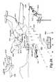
- FIG. 38is an environmental view of a dashboard and pulsed light signaling system engaged to an emergency vehicle
- FIG. 39is an alternative partial phantom line view of a pulsed light signaling system
- FIG. 40is an alternative partial phantom line view of a pulsed light signaling system
- FIG. 41is an environmental view of the controller of the pulsed light signaling system within the cockpit of an aircraft;
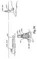
- FIG. 42is a detailed alternative view of the hand held pulsed light signaling system
- FIG. 43is a detailed view of the LED pulsed light communication system
- FIG. 43Ais an alternative detailed view of the LED pulsed light communication system
- FIG. 43Bis an alternative detailed view of the LED pulsed light communication system
- FIG. 43Cis an alternative detailed view of the LED pulsed light communication system.
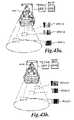
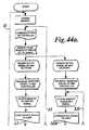
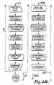
- FIGS. 44A-Cconstitute a block diagram of the operation of the first, second, and third controllers within the LED pulsed light communication system.
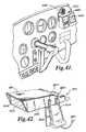
- FIG. 45illustrates by isometric projected view a first embodiment of a slave clock combined with optical transmitter and receiver in accord with the teachings of the present invention.
- FIG. 46illustrates by isometric projected view a second embodiment of a slave clock combined with optical transmitter and receiver in accord with the teachings of the present invention.
- FIG. 47illustrates by projected environmental view an embodiment of a communications network incorporating master and slave synchronized clocks.
- FIG. 48illustrates by front environmental view an embodiment of a building communication and management system within one room or space, using a single slave clock to communicate with a variety of diverse devices through optical LED communication channels.
- FIG. 49illustrates by block diagram an electrical schematic of a communications network incorporating master and slave synchronized clocks such as illustrated by FIG. 47 , but with only one slave clock illustrated therein.
- the LEDsmay be formed of the same or different colors.
- the controllermay be configured to select the color of the LEDs to be illuminated forming the light signal.
- controllermay control supports having multiple sides, such that each side is capable of producing light signals or combinations of light signals that are independent and/or different from those produced upon the other sides.
- the controllermay regulate the illumination of the LED light sources individually, or in combination, to provide a desired light signal or LED signal. Also, the controller may illuminate the LED light sources independently with respect to an opposite side of a support to provide different light effects to be observed by an individual dependant upon the location of the person relative to the light source. The controller may also simultaneously or independently regulate the light intensity for the LED illumination sources.
- the controllermay also regulate and/or modulate the duty cycle for the light sources, thereby varying the intensity of the observed light.
- the controllermay be utilized to simultaneously provide modulated or variable light intensity to different and/or independent sections, areas, and/or sectors 326 of a light source ( FIG. 23 ).
- the controllermay be utilized to simultaneously provide modulated or variable light intensity to different and/or independent sectors, areas, and/or sections 326 of the forward facing side or rearward facing side of a light support for the provision of different light signals, or a different light effects, on each side.
- FIG. 1depicts an exemplary embodiment 110 of an LED light and communication system.
- FIG. 1shows a server PC 112 connected via a USB cable 114 to a server optical transceiver (XCVR) 116 , and a client PC 118 connected via a USB cable 120 to a client optical transceiver 122 .
- the server PC 112is in communication with a network 123 via a CAT-5 cable, for example.
- the server optical XCVR and the client optical XCVRare substantially similar in at least one embodiment.
- An exemplary optical XCVR (or, simply, “XCVR”) circuitincludes one or more LEDs 124 for transmission of light and one or more photodetectors 126 for receiving transmitted light.
- photodetectorincludes “photodiodes” and all other devices capable of converting light into current or voltage.
- photodetector and photodiodeare used interchangeably hereafter.
- the use of the term photodiodeis not intended to restrict embodiments of the invention from using alternative photodetectors that are not specifically mentioned herein.
- the XCVR circuitmay include an RS232 to USB conversion module.
- the transmit pin on the USB conversion moduledrives the driver electronics for the LEDs.
- the XCVR circuitincludes high intensity LEDs. In some embodiments it may be desirable to use high intensity LEDs to enhance lighting, to improve data transmission, or both. In at least one embodiment, a 12 volt DC, 3 amp power supply is sufficient for powering an array of high intensity LEDs.
- the XCVR circuitfurther includes an amplifier for amplifying the optical signal received by the photodiode.
- the output of the amplifiermay be fed into level shifting circuitry to raise the signal to TTL levels, for example.
- the signalis then fed into the receive pin of the RS232 to USB module.
- a 9V batterycan be used to power the amplifier circuitry.
- Significant noiseis generated by switching high brightness LEDs on and off at 200 mA and 500 kbps, for example. Powering the amplifier with a battery can reduce these noise problems by reducing or removing transients.
- the LEDcan both emit and receive light.
- the LEDcan act both as a transmitter or receiver. More information on such bi-directional LEDs can be found in U.S. Pat. No. 7,072,587, the entire contents of which are expressly incorporated herein by reference.
- the XCVR circuitcan be a Universal Serial Bus (USB) dongle, such as shown in FIGS. 8A-8D , or similar device that is plugged into a laptop computer or other USB-configured device.
- USB dongle 1000includes a USB plug 1020 which is in the preferred embodiment most desirably compatible with standard USB connectors found on many devices. USB connectors are found on nearly all recently manufactured printers, PCs, flash drives, portable media players such as MP-3 and video players, and a plethora of other devices.
- USB plug 1020is preferred, owing to the wide availability of USB-enabled client devices, it is contemplated herein that the physical and electrical interface may comprise other standards or alternative constructions. As but one example, an IEEE-1394 (Firewire) interface may be provided alternatively or in addition to USB plug 1020 .
- USB dongle 1000is in the most preferred embodiment physically small, such that it may plug into diverse client devices for the purpose of providing data access and communication without mechanically interfering with the placement or use of the client device.
- USB dongle 1000communicates through a light communications channel. Data signals carried upon an optical transmission are received from a host through photodetector 1040 . Data signals are transmitted to the host by LED 1060 . Most preferably, photodetector 1040 and LED 1060 are isolated by a visible barrier, which may be a simple protrusion 1080 . Recesses and other optical barriers are further contemplated herein to serve as isolation from emitter-receiver feedback.
- USB dongle 1000is enabled to electrically connect to any client that accepts USB plug 1020 , or other connector substituted or provided in addition thereto.
- FIG. 8Eillustrates through schematic block diagram an exemplary electrical design of a USB dongle.
- the USB donglewill have to obey the electrical and communications specifications for the particular connection type. Consequently, in the preferred embodiment, the USB dongle will comply with both physical and electrical USB specifications through a suitable connection apparatus 1120 , allowing connection to a USB host.
- the USB-compliant signal 1130is not, in the preferred embodiment, the preferred signal format for optical transmission or reception. Consequently, transmission of USB-compliant signals 1130 will require conversion through conversion apparatus 1140 to suitable optical transmission format required at transmit signal 1200 .
- conversion apparatus 1140will, in accord with the preferred embodiment, be configured to provide the selected electrical conversion.
- Transmit circuitry 1210may, in the preferred embodiment, simply be appropriate buffering, isolation, modulation or amplification circuitry which will provide appropriate voltage and power through drive signal 1220 to adequately drive LED 1230 into producing a data-bearing visible light transmission 1240 .
- Exemplary of common transmit circuitryare operational amplifiers (op-amps) and transistor amplifiers, though those skilled in the art of signal conditioning will recognize a plethora of optional circuits and components which might optionally be used in conjunction with the present invention.
- the data-bearing visible light transmissionmay further be modulated, using FM, AM, PWM, PPM, OFDM, QAM or other known modulation techniques.
- USB dongle 1000also incorporates reception circuitry for receiving data from a data-bearing visible light wave input signal 1160 .
- Data-bearing visible light wave 1160will be detected by light sensor 1170 and converted to a data-bearing electrical signal 1180 .
- Receive circuitry 1190will appropriately condition, and may further convert data-bearing electrical signal 1180 .
- receive circuitry 1190may additionally demodulate data-bearing electrical signal 1180 , if the data stream has been modulated by an optical host, and suitable buffering, amplification and other conditioning may be provided to yield a received data signal 1150 .
- Conversion apparatus 1140will convert received signal 1150 to a USB-compliant signal 1130 .
- USB dongle 1000uses light as the communications channel between client and host, which improves security, reliability, system testing and configuration, bandwidth, infrastructure, etc. Security is greatly increased because light does not go through walls, in contrast to radio communications, and steps can be taken to obstruct visible transmissions with a much greater certainty than with high frequency radio waves. Furthermore, the visible light may additionally be limited or directed by known optical components such as lenses and reflectors to selectively form beams, as opposed to omni-directional transmissions.
- optical linkdoes not interfere with existing communication systems like those that are common today. Consequently, the preferred embodiment may be used in a variety of applications where prior art systems were simply unable due to EMI/RFI considerations.
- a host lamp fixture systemreplaces stationary (mounted in a particular place) lighting fixtures in order to communicate data. Inside of LED lights there may be one or many dies; these may pulsate on slightly different frequencies from a single light to communicate. Each may be looking for changes by way of Multiple Channel Access or other suitable technique.
- a clientsuch as a laptop
- the hostresponds with the location of the channels.
- Lights in a ceilingwill communicate with any capable transceiver.
- One suitable methoduses BPL (Broadband over Power Lines) for network connection, taking data and embedding it into a carrier frequency or group like radio, but instead using power lines or wave guides for transmission throughout an existing set of power lines within a building.
- BPLBroadband over Power Lines
- a buildingneeds to be wired only for lights, saving a huge infrastructure of other wires and fixtures, saving a great deal of money.
- the optical XCVRsinclude modulation circuitry for modulating a carrier signal with the optical signal.
- Modulationcan be used to eliminate bias conditions caused by sunlight or other interfering light sources.
- Digital modulationcan be accomplished by using phase-shift keying, amplitude-shift keying, frequency-shift keying, quadrature modulation, or any other digital modulation technique known by those of ordinary skill.
- XCVRscan include demodulation circuitry that extracts the data from the received signal. Modulation and demodulation techniques for modulating light signals are known by those of ordinary skill in the art. Examples of such techniques are described in U.S. Pat. Nos. 4,732,310, 5,245,681, and 6,137,613, the entire contents of each being expressly incorporated herein by reference.
- the optical baseband signalcan be modulated at 100 kHz and then transmitted.
- the XCVR that receives the 100 kHz modulated signalcan include a filter stage centered at 100 kHz.
- the filtered 100 kHz signalcan then be input into the amplifier circuitry, thereby preventing amplification of unwanted signals.
- FIGS. 2-4depict an embodiment of the present invention.
- an application of the LED light and communication system of FIG. 1is shown.
- the LED light and communication systemis integral to a broadband over power line (BOPL) communications system.
- FIG. 2shows a simplified block diagram of how Internet access can be provided with the optical XCVR described with respect to FIG. 1 .
- an Internet Provider 140connected to the Internet 142 , provides Internet Access 144 via fiber optic cable 146 , or other transmission medium, to a power substation 148 (4 kV-30 kV, for example).
- a power line bridge 150is provided that can modulate, alter, or otherwise adapt the Internet signals (not shown) for transmission over the power lines. As mentioned above, this is a simplification. More information may be found in U.S. Pat. No. 7,349,325, the entire disclosure of which is expressly incorporated herein by reference.
- the term “power line bridge”is used to denote any device that is capable of injecting Internet signals onto power lines, whether it is located at a substation or power line, home, business, etc., or any device that can extract an Internet signal from the power lines in a home, business, etc.
- the data signalsexit the distribution substation on the distribution bus (not shown) and are then injected onto the power lines 152 (either overhead or, preferably, underground).
- the power linesare fed to street lights 154 .
- Each street light 154is adapted to use an optical XCVR, such as those described above.
- the optical XCVRscan be used in conjunction with current street lamp light sources.
- Prior to broadcasting the data via a light signal from the LED street lightthe data must be extracted via demodulation techniques from the power supplied to the street light (not shown).
- An exemplary street lightis shown in FIG. 6 .
- street lampsas an Internet connection point takes advantage of the ubiquity of street lighting. Additionally, a major problem for amateur radio enthusiasts would be dramatically reduced by the use of street lights in the above manner. Amateur radio enthusiasts are greatly concerned with the noise generated and radiated when power lines are used for broadband transmission. However, electricity is generally supplied to street lamps via underground cables and through internal wiring in the street light columns (see FIGS. 6 and 7 for example). This design significantly reduces the amount of RF noise radiated during transmission of the signals. And, when finally broadcast, the signal is in light form and is thus not a source of RF noise.
- FIG. 3shows a graphical representation of how the street lights of FIG. 2 form an optical link 156 with customers 158 .
- FIG. 3residential homes are depicted, but the technology can of course be used for commercial, industrial, or any other customer desiring broadband access.
- the optical XCVRs in the street lightstransmit light to and receive light from the optical XCVRs 160 that are placed at the customer site.
- FIG. 4is a simplified block diagram depicting how a customer's optical XCVR provides Internet access to the customer via the customer's electrical wiring.
- the customer's optical XCVR 160is in operative communication with a power line bridge 150 .
- the power line bridge 150modulates the signal sent via the street light and injects the modulated signal onto the customer's electrical wiring 162 , usually at 120-240 VAC.
- the modulated signalis injected onto the electrical wiring at the electrical mains feed at the circuit breaker panel. This embodiment injects the signal to all electrical circuits at the customer site, providing access to the signal on each electrical circuit in the home, etc.
- the modulated signalcan be injected onto specific electrical circuits, if desired.
- another power line bridge 150is used to demodulate the signal from the electrical power.
- a power line bridge similar to a BellSouth®Powerline USB Adaptermay be used.
- a power line bridgecan also be Ethernet compatible. The power line bridge can plug into an electrical outlet, demodulate the signal from the electrical power, and transmit the signal to electronic equipment requiring Internet access.
- the signalis in operative communication with the electronic equipment via cables, such as Ethernet cables.
- the power line bridge plugged into the electrical outletincludes an optical XCVR, and instead of cables, an optical link provides the transmission medium to the electronic equipment.
- the light signalcan be modulated, if desired.
- another optical XCVR in communication with the electronic equipmentreceives and transmits data.
- an optical XCVRprovides lighting for one or more rooms on the customer premises.
- a power line bridgethat demodulates the signal from the electrical power that supplies power to AC/DC converter that supplies power to the LED array of the XCVR.
- the power line bridgesends the demodulated signal to the optical XCVR for transmission.
- each room at a customer premisecan be either be designed for or retrofitted with optical XCVRs in the ceiling, for example, for lighting.
- the main light source in the roomdoubles as an optical link for electronic equipment. Because the optical XCVRs are located in the ceiling, there are few items that can block the light signal.
- Injecting the signal onto the electrical wiring and providing an optical link through LED lightingis advantageous over wireless DSL modems. Often times, metal shelving or other structures on the premises interfere with or even block RF signals, thereby requiring multiple access points. However, providing an optical link through LED lighting in each room, for example, inherently provides multiple access points.
- Internet accessis provided to a customer's electrical wiring by standard BOPL techniques, without the use of LED lighting in street lights, for example, such as described in U.S. Pat. No. 7,349,325 and shown in FIG. 5 .
- the signalcan be extracted and broadcast over an optical link using optical XCVRs, as described above.
- traffic signalscan include optical XCVRs.
- vehiclescan be receiving information as they drive along streets.
- security badgescan include optical XCVRs, as shown in FIG. 10A .
- the optical XCVR of a user's security badge 170communicates with the optical XCVRs 160 that are also acting as room lighting, hall lighting, or other lighting 161 in a customer's facility, as shown in FIG. 10A .
- the optical XCVRscan be placed in numerous other locations as lighting sources. Using the XCVRs as light sources can reduce energy consumption and simplify communications by reducing the filtering or modulation complexities necessary to distinguish data signals from extraneous lighting sources. As shown in FIG.
- a useris shown with a name tag 170 that is broadcasting and receiving data over an optical link 156 using the XCVR described in FIG. 10A to a ceiling mounted fixture.
- Badge 170is pinned to, affixed with or otherwise transported by a person, in the embodiment as illustrated as a replacement for standard security identification badges.
- Badge 170is illustrated in greater detail in FIG. 10B , and may include features commonly found in standard security identification badges, including but not limited to such attributes as a photograph 1100 of the person assigned to the badge, and indicia such as employee identification or number 1200 , name 1220 , and business or entity logos 1240 .
- Business or entity logos 1240 , or other componentsmay integrate anti-counterfeiting technology as may be available or known for such diverse applications as passports, driver's licenses, currency and other applications. Commonly used devices include holograms, watermarks, special materials or unique threads, and embedded non-alterable electronic, visible, sonic or other identification codes.
- An optical transmitter 1300 and receiver 1320are most preferably provided and enable communication over optical communications channel 156 .
- a microphone, loudspeaker, microphone and speaker combination, or dual-purpose device 1400may be provided to integrate an auditory communication channel between communication badge 170 and nearby living beings or other animate or inanimate objects.
- a video camera 1420may be incorporated to capture video or still pictures.
- a video display 1500may additionally be incorporated into communication badge 170 , permitting information 1520 to be displayed thereon, which could for exemplary purposes could comprise either text or graphics.
- photograph 1100may in some cases be eliminated and replaced entirely by an electronic representation displayed within video display 1500 either continuously or upon request or polling.
- indiciasuch as employee identification or number 1200 , name 1220 , and business or entity logos 1240 may also be provided either as illustrated in FIG. 10B , or in another embodiment solely upon video display 1500 .
- Biometric detectors and systemsmay be employed within or in association with communication badge 170 .
- a fingerprint reader or other biometric detectormay be incorporated within badge 170 .
- periodic or action-driven re-activationmay be required to verify that badge 170 is still in proper possession of the person assigned therewith.
- the security systemin accord with an embodiment of the present invention may communicate through badge 170 to person and require a fingerprint verification scan.
- Other biometric indicatorsmay not require active confirmation, and more than one biometric indicator may be incorporated herein.
- Communication badge 170communicates with XCVR 160 in LED light source 161 .
- LED light source 161illustrated by magnified view in FIG. 10C as a body 2050 that incorporates at least one, and preferably a plurality of LEDs and optical detectors.
- One or more photodetectors 2200may be provided, and may either be broad spectrum detectors or alternatively color-filtered or sensitive to only a single color.
- the detectorwill be any of the myriad known in the art, the particular selection which will be determined by well-known considerations such as sensitivity, reliability, availability, cost and the like.
- LEDsare in clusters of three.
- these LEDsare RGB LEDs, designating that they include red, blue and green which are the primary additive colors from which all other colors including white may be produced.
- LED 2100may generate red light, commonly of approximately 650 nanometer wavelength
- LED 2120may generate blue light, commonly of approximately 475 nanometer wavelength
- LED 2140may generate green light, commonly of approximately 565 nanometer wavelength.
- LEDs 2100 - 2140may be discrete components, or may alternatively be integrated onto a common die and take the physical form of a single LED.
- more than one RGB LEDmay be integrated upon a single die or within a common package, as may be deemed most appropriate by a manufacturer.
- a plurality of RGB LEDsmay also be provided upon or within a single body 2050 , as illustrated in FIG. 1C by RGB LEDs 2100 ′, 2120 ′ and 2140 ′.
- RGB LEDs 2100 ′, 2120 ′ and 2140 ′there is no limit to the number of RGB LEDs that may be used, other than physical size and available space limitations, and thermal dissipation capacity and power requirement constraints.
- RGB LEDs 2100 - 2140By controlling the relative power applied to each one of the RGB LEDs 2100 - 2140 , different colors may be produced. This concept is well-known as the RGB model, and is used today in nearly all video displays. Color televisions and computer monitors, for example, incorporate very small red, green and blue (RGB) dots adjacent to each other. To produce white regions on the screen, all three RGB dots are illuminated. Black dots are the result of none of the RGB dots being illuminated. Other colors are produced by illuminating one or more of the dots at different relative levels, or alternatively controlling how many closely adjacent dots of one primary color are fully illuminated relatively to the other two primary colors.
- RGBred, green and blue
- color temperature of an LED light panel 2000may be adjusted or controlled, and may be varied in real time without making any hardware or apparatus changes. Instead, power applied to the RGB LEDs is adjusted to favor one or another of the RGB LEDs 2100 - 2140 . Since the light emitted from the RGB LEDs is approximately full-spectrum light, the color-rendering index may also be relatively high, particularly when compared to mercury or sodium vapor lamps, making the light feel very natural.
- RGB LEDs 2100 - 2140safeguards may be programmed or designed into the control of RGB LEDs 2100 - 2140 to prevent occurrence of conditions that could lead to blue-light hazard or other safety hazard that might potentially exist.
- RGB LED absent of phosphorsWhile other options exist for producing white light from LEDs, the use of an RGB LED absent of phosphors is preferred for most applications of the present invention. Not only is color of the light easily controlled using well-known RGB technology, but also by their very nature phosphors tend to slow down the rate at which an LED may be illuminated and extinguished due to phosphor latencies. For the purposes of the present invention, where an optical communications channel 156 is created between XCVR 160 and one or more communications badges 170 , higher data transfer rates may be obtained with more rapid control of illumination levels. Consequently, if phosphors are used in the generation of light from LED light source 161 , and if faster data exchange rates through optical communications channel 156 are desired, these phosphors will preferably be very fast lighting and extinguishing.
- light source 161may replace a standard fluorescent tube light fixture. This can be accomplished by replacing the entire fixture such that ballasts and other devices specific to fluorescent lighting are replaced. In many cases, this will be the preferred approach.
- the fixturemay then be wired for any suitable or desired voltage, and where a voltage or current different from standard line voltage is used, transformers or power converters or power supplies may be provided. When a building is either initially being constructed, or so thoroughly remodeled to provide adequate replacement of wires, the voltage may be generated in transformers that may even be provided outside of the occupied space, such as on the roof, in a utility room, basement or attic. In addition to other benefit, placement in these locations will further reduce requirements for air conditioning.
- LED base 2050may be designed to insert directly into a standard fluorescent socket, such as, for exemplary purposes only and not limited thereto, the standard T8 and T12 sockets used in the United States.
- RGB LEDs 2100 - 2140are arranged and wired to directly operate from line voltage, or appropriate electronics will need to be provided directly in LED base 2050 to provide necessary power conversion.
- power conversionmay be provided through switching-type or other power conversion circuitry to alleviate the need for any rewiring, though in these instances the power conversion circuitry will need to accommodate the particular type of ballast already in place.
- LED bulbsmay similarly accommodate the fixture.
- incandescent replacementno rewiring or removal of ballasts is required, since line voltage is applied directly to incandescent fixtures. Consequently, appropriate conversion may in one conceived alternative embodiment simply involve the replacement of a bulb with no fixture or wiring alterations.
- communications circuitryFor LED light source 161 to replace an existing bulb, regardless of type, and benefit from the many features enabled in the preferred embodiment, communications circuitry must also be provided. This communications circuitry is necessary to properly illuminate each of the red, green and blue LEDs to desired color, to transport data through optical communication channel 156 .
- LEDsare used to transmit through optical communication channel several kinds of data, including identity, location, audio and video information.
- the use of an optical communications linkprovides large available bandwidth, which in turn permits multiple feeds of personal communication between LED light sources and badges similar to or in excess of that of cell phones.
- the optical datais transferred at rates far in excess of those detectable by the human eye, and so a person is not able to detect any visible changes as the data is being transferred. Additionally, because optical illumination is constrained by opaque objects such as walls, the location of a badge and associated person can be discerned to a particular room, hallway or other similar space.
- prior art GPS systems and cell phone triangulation techniquesare typically only accurate to one or several hundred feet. Horizontally, this prior art precision is adequate for many applications. However, vertically several hundred feet could encompass twenty floors in an office or apartment building.
- the preferred embodimentcapable of precision to a room or light fixture, therefore has much more exact pinpointing than hitherto available. It can locate a person immediately, even in a large area and/or among a large crowd, and can keep track of a large population simultaneously. As noted, the large bandwidth permits video signals to be integrated with badge location and movement, providing the opportunity to create audio-video records that are fixed in time and location.
- optical transmitter 1300 or LEDs 2100 - 2140 of FIG. 10Bmay in one embodiment be configured to change color, flash, or otherwise be visually changed or manipulated to assist with directional guidance, personnel or intruder identification, energy management, or to facilitate the meeting and connection of individuals.
- a buildingneeds to be wired only for lights, saving a huge infrastructure of other wires and fixtures.
- the name tag 170 XCVRinclude any or all of the following devices: a microphone 172 , a speaker 174 , a rechargeable battery 176 , and a video camera 178 , as shown in the simplified block diagram of FIG. 9 .
- the microphoneis in communication with an analog-to-digital converter (ADC)(not shown) for converting the analog speech input to a digital signal.
- ADCanalog-to-digital converter
- An amplifier circuit 180can be used to boost the microphone signal. The signal can be amplified prior to or after the ADC.
- the speakeris communication with a digital-to-analog converter (DAC)(not shown) for converting the received digital signal to an analog output.
- An amplifier circuit 182can be used to boost the speaker signal.
- the signalcan be amplified prior to or after the DAC.
- the processor 184 shown in FIG. 9converts the digital signals from the microphone/amplifier to data packets that can be used for transmission by the optical XCVR. Similarly, the processor converts the data packets received by the optical XCVR to audio out signals directed to the speaker. The processor can convert data packets received from or directed to the video camera.
- the term “processor” as used hereinrefers to a processor, controller, microprocessor, microcontroller, or any other device that can execute instructions, perform arithmetic and logic functions, access and write to memory, interface with peripheral devices, etc.
- the usercan use the name tag as a communication device.
- the usermay use the name tag to stream music, or video if a display is included.
- the optical XCVRcan also include non-volatile memory (FLASHRAM, EEPROM, and EPROM, for example) that can store firmware for the optical XCVR, as well as text information, audio signals, video signals, contact information for other users, etc., as is common with current cell phones. While a hard-drive may be used instead of these semiconductor-based memory devices, hard-drives may be impractical in some embodiments based on their size, access times, as well as their susceptibility to jarring.
- the optical XCVRincludes one or more photodetectors 126 for receiving transmitted LED or other light signals, and one or more LEDs 124 for transmitting LED signals, as shown in FIG. 9 .
- an optical signal amplifier 186is in communication with the photodetectors to increase the signal strength of the received light signals.
- the LEDsare in operative communication with an LED power driver 188 , ensuring a constant current source for the LEDs.
- the name tagmay include circuitry that performs modulation, demodulation, data compression, data decompression, up converting, down converting, coding, interleaving, pulse shaping, and other communication and signal processing techniques, as are known by those of ordinary skill in the art.
- the name tag of FIGS. 9 and 10is embedded with a unique code, similar in principle to the MAC address of a computer, for example. Thus, every name tag has a unique identifier.
- the name tagbroadcasts the unique code at regular intervals, or irregular intervals if desired.
- Optical XCVRs located within the user's building and near the usercan then receive the unique code transmitted by the name tag.
- an optical XCVRis engaged to a door lock.
- the name tagbroadcasts the unique code
- an optical XCVR in communication with the door lockreceives the code, and if acceptable, unlocks or opens the door.
- a table of acceptable codesmay be stored in a memory device that is in communication with, and accessible by, the door's optical XCVR.
- the door's optical XCVRmay transmit a code to a central station that compares the user's code against a table of approved codes and then sends a response either allowing or denying access.
- the electrical wiring in the hallways and/or roomsmay include BOPL.
- the name tagmay be used to provide access to the Internet via the optical XCVRs in the hallways and rooms.
- a person walking down the hallwaymay receive a phone call on their name tag from a person on the other side of the world as long as the other person was using the Internet to communicate and knew the unique code of the name tag.
- Such communicationis possible because the Internet is based upon transmission of packetized data, a form ideally suited for use with an optical XCVR.
- FIG. 12illustrates a simplified block schematic diagram of an electrical circuit used to couple power and data to one or a plurality of LED light sources 161 .
- Powerwhich may be either AC or DC current is coupled through a power line bridge 150 with data from a network cable input, for example.
- the source of the datais not critical to the operation of the present invention, but may include various computer outputs such as might, for exemplary purposes, include control processor output or network connections such as commonly found on Local Area Networks (LAN), Wide Area Networks (WAN) or through the Internet.
- LANLocal Area Networks
- WANWide Area Networks
- the wiring between power line bridge 150 and LED light source 161is shielded by passing through a conduit or the like, defining a Shielded Broadband-over-Power-Line (S-BPL) connection that is both resistant to interfering communications and also produces almost no radiant energy.
- S-BPLShielded Broadband-over-Power-Line
- the name tagmay be used in conjunction with the LED lighting in hallways, rooms, etc. to reduce energy consumption, as shown in FIG. 11 .
- all the lights in a hallwaymay have a standby setting such that they are relatively dim or even off.
- a transmitted signale.g. the unique code of the name tag.
- the lightreturns to its standby setting of dim/off brightness through a signal communicated from a XCVR at a sufficiently remote location to indicate that the individual has passed, and is no longer present at this particular location.
- the presence of an individual proximate to an XCVRmay be determined by either recognition of a signal or through the failure to continue to recognize a signal or by a proximity calculation as based on a controller receiving a signal from a remote location which indicates recognition of a name tag. A proximity is then calculated where initial or previous XCVR light sources are extinguished as an individual passes a particular location.
- the lightscan gradually become brighter, as a percentage of full brightness, as a person approaches, and then gradually dim, as a percentage of full brightness, as a person moves away based on proximity calculation as earlier described.
- the lights shown in FIG. 11will have AC wiring with data carriers such as S-BPL, and static locations encoded into the system.
- a person 190 entering a hallway 192 with a communications badge 170could use only those lights needed for his travel.
- the lights behind the personmay be no longer needed and so may be programmed to turn off.
- These lightscould function variably from 10 to 100% brightness as needed, for example.
- the person 190is approximately adjacent to light 505 and traveling in the direction shown by arrow 15 towards light 506 . From this position, person 190 might prefer to be able to see into the branching corridor containing lights 509 - 511 .
- the illumination of these neighboring lightscan be increased, to provide sufficient illumination to ensure the safety of person 190 .
- an embodiment of the present inventionmay incorporate custom programming of such features by individual person 190 , or within standard preset selections, such as “cautious” where a relatively large number of lights are illuminated adjacent to person 190 , or “carefree,” where only a minimum number of lights are illuminated.
- the level of illuminationmay additionally vary with relation to the person, the geometry of the building space, in accord with personal preferences, or for other reasons.
- lights 509 - 511When person 190 has traveled farther, lights 509 - 511 may be extinguished, in effect providing a moving “bubble” of illumination surrounding person. Other lights are automatically shut-off or dimmed as desired and controlled by program. As FIG. 11 further illustrates, lights within a room 20 may similarly be activated and controlled. For exemplary purposes as illustrated, light 531 may be at full intensity, lights 521 - 528 may be extinguished completely, and light 520 may be operating in a greatly dimmed state, but still providing adequate lighting to ease person 190 .
- the present inventionreduces the extent of human interaction required to control various functions such as light switches and thermostats, while simultaneously increasing the capabilities of such controls.
- Individual or selected groups of lightsmay be selectively configured for optimal physiological and psychological effects and benefits for one or more applications, and then may be readily reconfigured without changes to physical structures for diverse applications having different requirements for optimal physiological and/or psychological effects and benefits.
- Such embodimentsare an improvement over conventional motion detectors, due to the “smart” nature of the optical XCVRs.
- the optical XCVRs(and in some embodiments the optical XCVRs in conjunction with software) in the lighting fixture recognize immediately that the person has moved beyond a particular light, allowing that particular light to be dimmed or turned off.
- this smart technologymay be used to turn lights on only for people with the correct code embedded in their name tag. In such an embodiment, the user can walk into a restricted area, and if not authorized to be there, the lights would remain off, and if authorized the lights would turn on.
- a teacher with a name tag grading papers in a classroommay use the name tag to turn on only the lighting near the teacher's desk at full brightness, while other lighting in the room remains at a dimmer, more energy efficient, setting.
- Peak inrush currentis also an important factor monitored by many utility companies. This is the peak power draw of the power customer, for exemplary purposes within each twenty-four hour period.
- electrical drawmay be gradually ramped up. Many devices initially draw more power at start-up than when operational. So, since each light is individually addressed and controlled and appliances or machines may similarly be controlled, the communications afforded by the present invention permit much smaller banks of devices to be started, allowing those devices to surge and then settle to lower energy requirements before starting the next bank of devices. Some devices and machines very quickly drop down to lower power draw. LED light sources are such a device. Banks of these may very quickly and sequentially be started.
- numbers of occupants within a spacemay be used not only for anticipating illumination, but also to control operation of other appliances and machinery within the building.
- the name tagmay be used to assist emergency personnel. For example, if a person with a name tag had an incapacitating emergency condition while walking along a hallway in a building with optical XCVRs, as in the embodiments described above, the hallway lighting can be modified to direct emergency workers directly to the injured person.
- the lightscan be made to flash, change color, or form directional arrows, or sequential directional indicators, or otherwise signify to the emergency personnel the quickest path to the person.
- some embodiment of the present inventionare directed towards security and detection of intruders.
- the present preferred apparatusmay be used to detect and locate the intruder. Since the building is dark, in many cases an intruder will rely upon a flashlight to move through the building. Most preferably, the XCVR will detect this unidentified light source. Optionally, an attempt will be made through the XCVR to communicate with the unidentified light source. A failure to communicate will indicate an intruder or unauthorized access. In such case, since the location of XCVR is known precisely, the location of the intruder is also known.
- the intruderwill be tracked by virtue of the light emitting from the intruder's flashlight.
- lightsmay be used to guide the emergency personnel to the exact location of the intruder.
- the emergency personnelmay not be limited to police.
- ambulance workers as well as policewould appreciate flashing directional lights because quicker access to an emergency scene could potentially save lives.
- This custom guidance systemcan include red, white or other suitably colored or illuminated lights which may be steady or flashing for emergency situations.
- Corridor lights and/or individual communication badgesmay be equipped to flash, directing emergency personnel to a desired location or person.
- the communication badgemay communicate with prior art screening equipment, such a metal detectors, x-ray machines, drug and explosives sniffers, and other such hardware.
- a building employing the present inventionmay incorporate multiple safety features. Instead of relying on several security guards at several stations to read badges and monitor each station, a proximity detector may first detect whether a person is passing through the entrance. If so, the adjacent LED light source will query for an appropriate or legitimate communications badge. Even if detected, if a badge has been duplicated, preferred logging and verification through software will instantly identify that the first person is already in the building. Consequently, the presently entering person and the person already in the building can both be located, and the intruder identified.
- biometricsmay additionally be incorporated, and for exemplary purposes a fingerprint scan or the like may be required to verify identity prior to passing through proximity/badge detector.
- the present inventionalso has the capability to provide low power communications for energy management, emergency back-up, security and special applications utilizing alternative power sources such as batteries or solar cells. Since each individual LED light source may be separately controlled, unnecessary lights may be extinguished in an emergency. Remaining lights may be used to signal emergency routes which may be emergency exits, predetermined shelter such as in the event of a tornado, safe locations potentially determined in real time in the event of an intruder or other hazard. The remaining lights may also or alternatively be used to maintain nominal communications channels within the building. The signals in such instance may be unable to be carried through power lines, and so may alternatively be implemented through a repeater function from one light to the next to travel entirely through a chain of LED light source.
- building lightingmay be modulated with time and date stamps or the like.
- Video recordings made within the space of modulated illuminationwill have an optical watermark automatically embedded therein. The embedding of such identifiable signals ensures the integrity of video recordings made under these lights.
- Building management in accord with another embodiment of the inventionfurther includes automated secured access control to apparatus such as doors, drawers, electronic computer operations, cars, thermostats, and any other devices that may be electronically controlled.
- apparatussuch as doors, drawers, electronic computer operations, cars, thermostats, and any other devices that may be electronically controlled.
- apparatussuch as doors, drawers, electronic computer operations, cars, thermostats, and any other devices that may be electronically controlled.
- LED communicationBy means of LED communication, the location of unauthorized devices as well as persons can be tracked or polled by the system. Doors, either locked or unlocked, can be manipulated in response to the location or movement of these devices or persons.
- the videocan be used to capture the last-known conditions of a user or an area. This can be important in the event a disaster strikes that results in significant destruction of property or life.
- An intelligent audio/visual observation and identification database systemmay also be coupled to sensors as disposed about a building.
- the systemmay then build a database with respect to temperature sensors within specific locations, pressure sensors, motion detectors, communications badges, phone number identifiers, sound transducers, and/or smoke or fire detectors. Recorded data as received from various sensors may be used to build a database for normal parameters and environmental conditions for specific zones of a structure for individual periods of time and dates.
- a computermay continuously receive readings/data from remote sensors for comparison to the pre-stored or learned data to identify discrepancies therebetween.
- filtering, flagging and threshold proceduresmay be implemented to indicate a threshold discrepancy to signal an officer to initiate an investigation. The reassignment of priorities and the storage and recognition of the assigned priorities occurs at the computer to automatically recalibrate the assignment of points or flags for further comparison to a profile prior to the triggering of a signal representative of a threshold discrepancy.
- the intelligent audio/visual observation and identification database systemmay also be coupled to various infrared or ultraviolet sensors, in addition to the optical sensors incorporated directly into LED light source, and used for security/surveillance within a structure to assist in the early identification of an unauthorized individual within a security zone or the presence of an intruder without knowledge of the intruder.
- the intelligent audio/visual observation and identification database systemas coupled to sensors and/or building control systems for a building which may be based upon audio, temperature, motion, pressure, phone number identifiers, smoke detectors, fire detectors and fire alarms is based upon automatic storage, retrieval and comparison of observed/measured data to prerecorded data, in further comparison to the threshold profile parameters to automatically generate a signal to a surveillance, security, or law enforcement officer.
- Security zones which may use intelligent video/audio observation and identification database systemmay include, but are not necessarily limited to, areas such as airports, embassies, hospitals, schools, government buildings, commercial buildings, power plants, chemical plants, garages, and/or any other location for which the monitoring of vehicle or individual traffic and/or security is desirable.
- An intelligent observation and identification database systemmay be arranged to learn the expected times for arrival and departure of individuals and vehicles from various zones. Each time an individual or vehicle enters or exits a security zone, the system may record in the database the time and location of the arrival or exit. Thus, over time, the system may learn the expected arrival and departure times based upon the average of predetermined times, such as normal shift times. Thus, if a vehicle of an individual attempts to enter or exit a zone at a time other than the learned expected time of entry or exit, the system may alert security personnel to initiate an investigation.
- a low level tracking prioritymay be accomplished by recording the location and time for each instance when the system identifies the vehicle or individual.
- a low level tracking prioritymay normally generate a log of when and where a vehicle or individual was seen.
- the systemmay learn typical paths, times and zones where specific vehicles and individuals spend their time. The system may then issue an alert when a vehicle or individual deviates from their normal path. For example, if a person normally may be found on the second floor, and they occasionally pass through first floor but have never gone to the fourth floor, then the system may alert security personnel if the person is identified by the system on the fourth floor.
- the intelligent audio/visual observation and identification database systemmay be coupled to the operational systems for a building, such as locking systems for doors, lighting systems, air conditioning systems, and/or heating systems.
- Another embodiment of the present inventionincorporates guidance and communications systems.
- the visitormay be guided through any suitable color or intensity pattern such as but not limited to flashing patterns, color changes or the like in LED light source or other similar fixtures to the location or person they seek.
- the person being sought outmay further be made conspicuous by similar changes in color or intensity pattern within the sought-person's communication badge, for exemplary purposes either within video display 1500 or optical transmitter 1300 , as shown in FIG. 10B .
- RGB LEDs of the present inventionis simply a matter of software control.
- location specific access intelligencemay also be incorporated.
- the pagermay remain silent. Once the doctor exits surgery, then the pager may be reactivated. This control may be automatic, simply incorporated into the programming of the system.
- studentsmay use the preferred communication badge for communications similar to cellular telephones, including text messaging, voice communications, web access, and so forth. However, upon entering a classroom, communications might in one embodiment then be disabled, ensuring the students are not distracted with unauthorized activities.
- audio and video communicationsare possible in accord with light communications in locations and environments where cellular or radio communications may be impossible, forbidden, or unreliable, extending existing communications systems.
- the name tag embodimentneed not be restricted to use by people.
- the name tag embodimentmay be associated with cars, for example.
- the car 205includes a tag (not shown) that broadcasts a unique code that may either turn street lights 154 on or increase the brightness of dimly lit street lights, as shown in FIG. 15 , similar to the hallway or room lights described above.
- a devicemay be used to indicate that a car is authorized to enter a restricted area.
- such a devicemay be used to pay tolls on highways or pay fees at a parking garage by uniquely identifying the vehicle and the account to be charged.
- such devicemay be used to open garage doors.
- GPSGlobal Positioning System
- the Global Positioning Systemis described in U.S. Pat. No. 4,785,463, the entire contents of which are expressly incorporated herein by reference.
- GPS positioninguses one or more coordinate systems, such as World Geodetic System 1984 (WGS84), to provide a reference frame, allowing every point on earth to be coded with a unique GPS location.
- WGS84World Geodetic System 1984
- a data packetmay include GPS location header bits that include the packet's destination address in GPS coordinates.
- the data packetmay further include GPS location trailer bits that include the packet's origin address in GPS coordinates.
- the data packetmay further include the address in GPS coordinates of the optical XCVR that most recently transmitted the packet (the last known transmission address, or LTA), as will be described in more detail below.
- the data packetfurther includes the data to be transmitted, and may include any other bits of information determined to be necessary for successful transmission of data, such as error detection bits, as understood by a person of ordinary skill in the art.
- Routing data packets from one location to another locationcan be accomplished using GPS location information tags data packets having a geographic location instead of a cyber location. Such an embodiment eliminates the need for any later geographic location translation because a data packet starts with geographic source and destination information. This simplifies locating the destination of the data packet.
- each data packetis assigned a GPS origin/destination address as it passes through the network infrastructure.
- the data packetis always searching for the next closest GPS address location.
- Each stationary (or static) optical XCVR, and some dynamic optical XCVRs, within a networkwill be designated with a GPS location number.
- As a data packet passes through the networkit is routed by the optical XCVRs, with their internal processors, to the next physically closer optical XCVR within the network. If another optical XCVR is within receiving range, or is connected with another form of communication medium, that optical XCVR receives the data packet.
- the optical XCVR's internal processorcompares its internal GPS location address (ILA) to the data packet's GPS destination address and the optical XCVR's last known transmission address (LTA) stored within the data packet. If the ILA code is closer to the data packet destination address than the LTA code stored within the data packet, the optical XCVR's processor inserts its ILA code into the data packet as the new LTA code and then repeats transmission of the entire data packet with the updated LTA code.
- An exemplary data packet 210 including GPS address informationis shown in FIG. 14 .
- the networkcontinues this process until the data packet reaches the destination optical XCVR, at which point the data packet is transmitted. If a piece of the infrastructure is missing, the packet will be rerouted to the next nearest optical XCVR and continue until it finds the shortest pathway through the network to the destination address.
- each user on the networkmay declare one or more static positions and also have a dynamic position.
- a static addressmay be a home, an office, etc.
- the networkmay track the user as the user passes optical XCVRs, similar to that of cell phones in relation to cell phone towers, and provide a dynamic address location. If a data packet begins with a destination address that is the user's static address, the network may update the packet with the user's new dynamic address and reroute the packet accordingly, in a scheme similar to that of cellular phones.
- FIG. 13shows railroad poles 215 adapted with optical XCVRs.
- the railroad poles 215 with optical XCVRsare shown in more detail in FIG. 7 .
- Each optical XCVR on a railroad polehas a known static GPS address. Because each optical XCVR has a unique code, as a user drives along the road, that specific user's dynamic GPS address location may be determined by the proximity of the user's optical XCVR to the static GPS address locations of the railroad pole, for example.
- street lights, traffic signals, sign posts, buildings, or other stationary structuresmay include optical XCVRs. Because of this interaction between the user's optical XCVR and the network's optical XCVRs, the network knows the dynamic GPS address of the user.
- a data packet initially routed to a user's static GPS addressmay be rerouted by the network to the user's dynamic location. It is unnecessary for the system to know the exact GPS location of the user; the system only needs to know the static GPS location of the closest static device (e.g. a railroad pole, street lamp, etc.) to the user so that the system may ensure the user will receive the broadcasted signal.
- a static GPS addresse.g. home, office, etc.
- an optical XCVR and its associated hardwaresimply stores its known static GPS location information.
- the optical XCVRmay be combined with a GPS receiver.
- a train 216 with an optical XCVR 160is shown having an optical link 156 with the optical XCVRs on the railroad poles 215 .
- the optical linkmay be used to provide Internet access to the train operator or the passengers.
- the optical linkcan also be used for switching purposes, ensuring that the train proceeds on the correct track.
- Exemplary street lights 154 and railroad poles 215 with optical XCVRsare shown in FIG. 6-7 .
- the street lights and railroad polescan include internal optics that allow for long range 2-way communication via optical link 156 .
- the street lights(and railroad poles, not shown) can include a light source 157 for general illumination and local data access.
- the street lights and railroad polesinclude a solar panel 159 and a battery in operative communication with its optical XCVR.
- the solar panelallows communication to continue in the event of a loss of power to the street lamp.
- the solar panelprovides the primary source of power in some embodiments for the optical XCVR in the railroad pole.
- GPS and optical XCVRsinclude tagging each optical XCVR in an office building, for example, with a unique GPS location. If User A, located in User A's office, attempted to contact User B, located in User B's office, but User B was instead located in User C's office, the transmission could be diverted to User C's office automatically.
- the data packet sent by User Aincludes User B's static GPS location address, namely User B's office, as well as User B's unique code.
- the networkis aware that User B is in User C's office because User B's optical XCVR is broadcasting its unique code to the optical XCVRs located in User C's office.
- the data packetis re-routed to one or more optical XCVRs to User C's office, and then broadcast directly to User B's optical XCVR.
- the re-routingmay be accomplished by routing all data packets to a base station.
- the base stationmay then determine if the static GPS destination address in the data packet is the correct destination, based on the current location of the destination optical XCVR, or if the GPS destination address needs to be modified based on the dynamic information of the destination optical XCVR. If the GPS destination address needs to be modified, the base station may replace the static GPS destination address with the appropriate address of the destination optical XCVR.
- the memory of a user's optical XCVRstores the unique code, the static GPS location address, or both, of another user's optical XCVR in its “phone book”, like a cell phone.
- the optical XCVRincludes a display, also like a cell phone, that allows a first user to find a second user's information and initiate communication with the second user.
- the name tag of FIGS. 9 and 10is embedded with a unique code, similar in principle to the MAC address of a computer, for example.
- every name taghas a unique identifier.
- the XCVRbroadcasts the unique code at regular intervals, or irregular intervals if desired.
- Optical XCVRs located within the user's building and near the usermay then receive the unique code transmitted by the name tag.
- a first usermay wish to use his optical XCVR to contact a second optical XCVR, used by John Smith.
- the first user's optical XCVRhas the unique code of John Smith's optical XCVR stored in its memory, or the static GPS location address of John Smith's optical XCVR stored in its memory, or both.
- the first useruses a display and/or keypad on the optical XCVR, the first user searches the phone book stored in this optical XCVR for John Smith's name, like a cell phone.
- the first userinitiates communication with John Smith. Because the first user's optical XCVR includes John Smith's contact information, the first user's optical XCVR is able create data packets with sufficient information to allow the network to route the packets to him, as described above.
- the optical XCVRmay be incorporated into a clock, preferably on the face of the clock, as seen in FIGS. 16-19 .
- the AC electrical wiring of a buildinge.g. school, office, etc.
- the buildingincludes a master clock 220 and one or more clocks 222 located throughout the building, each clock powered by the AC electrical wiring 224 , as seen in FIG. 19 .
- the master clock 220 and the other clocks 222are on the same electrical circuit.
- the master clockmay include a number of functions, including an annunciator panel.
- the annunciator panelmay be used to communicate fire alarms, tornado alarms, lockdowns, presence of an unknown person(s), etc. to annunciator panels on the other clocks.
- the master clockis in operative communication with a power line bridge 150 .
- the master clockincludes appropriate circuitry for encoding the alarm signals and transmitting them to the power line bridge onto the AC electrical wiring. The packets are then routed to clocks located in other rooms in the building to communicate the alarm signal.
- the other clocksinclude power line bridge circuitry for decoding the signal and a display and/or speaker for communicating the transmitted alarm.
- the clocks 222further include one or more optical XCVRs 160 that allow communication between other devices in a room that are equipped with optical XCVRs, such as thermostats 226 , smoke detectors 228 , cameras 230 , and PA speaker 232 , as seen in FIG. 18 .
- the optical XCVRs in the clockalso allow communication with other rooms and/or a central location. For example, upon sensing smoke, a smoke detector equipped with an optical XCVR broadcasts the signal, which is in turn received by the clock's optical XCVR and transmitted over the AC wiring to a central location as an alarm.
- Energy managementmay also be accomplished by using the optical XCVR on the clock to turn down/up a thermostat equipped with an optical XCVR, based on the time of day, or whether anyone is in the room.
- studentsfor example, may each wear one of the above-described name tags that broadcast a unique code.
- the optical XCVR in the clock in the roomis polling and does not detect any unique codes being broadcast in the room, it sends the information along to a central location that, in turn, instructs the optical XCVR in the clock to broadcast a signal to turn the thermostat up/down to save energy.
- a similar functionmay be performed with respect to the lighting in the room.
- the BOPL and optical XCVRsmay be used to provide Internet access, thereby allowing the optical XCVR on the clock to be the access point for the Internet connection. If a PA speaker is included in the clock, or is in communication with the clock as in FIG. 18 , the optical XCVR of the clock may also be used as a public address system to broadcast messages.
- the clock faceis an analog display, as seen in FIG. 16 .
- the clockis a digital clock, as seen in FIG. 17 .
- the LED segments 234act both as the display of the clock and as the LEDs used for transmitting data signals.
- the digital clockfurther includes one or more photodiodes 126 for receiving data signals.
- each student in a schoolwears a name tag with an optical XCVR.
- the optical XCVR on a name tagmay communicate with the optical XCVR on a clock to indicate whether a student in a classroom is present, or provide the student's location. In a normal classroom setting multiple students will be present.
- a channel access methodcan be provided to allow all students and teachers to use the clock's optical XCVR.
- a channel access methodlike time division multiple access (TDMA) may be used.
- TDMAsplits a signal into timeslots, with each user transmitting only in their allotted time slot.
- frequency division multiple access (FDMA), code division multiple access (CDMA), or other channel access methodmay be used to allow multiple optical XCVRs to transmit to a single optical XCVR.
- the optical XCVR associated with the clockfor example, is constructed and arranged such that each photodiode acts as a separate receiver channel.
- the multi-channel optical XCVR on the clockmay be used for parallel processing of received data, for example 30 students with unique name tags transmitting simultaneously. In such an embodiment, it may not be necessary to use channel access methods because the optical XCVR is designed with sufficient channel capacity to handle all incoming traffic.
- the processor of the optical XCVRmay simultaneously process all incoming signals. In embodiments where the processor cannot simultaneously process all incoming signals, it may be desirable to include buffers to buffer the incoming signals so that signals are processed according to the time they were received.
- the optical XCVR associated with the clockis constructed and arranged such that each LED acts as a separate transmission channel.
- the multi-channel optical XCVR on the clockmay be used for parallel transmission of data, for example. That is, each LED in the LED array of the optical XCVR may be used to broadcast a different data stream. So, LED 1 could broadcast a data stream to computer 1 , and LED 2 could simultaneously broadcast a different data stream to computer 2 , and LED 3 could simultaneously broadcast a different data stream to computer 3 , etc.
- the optical XCVR in a clockis an exemplary embodiment.
- a multi-channel optical XCVRmay be embodied in numerous other devices, or as a standalone device.
- the LEDsmay be bi-directional.
- the optical XCVRis comprised of bi-directional LEDs.
- the optical XCVRis constructed and arranged such that at least one of the bi-directional LEDs allows parallel transmitting and receiving of light signals.
- processorrefers to a processor, controller, microprocessor, microcontroller, mainframe computer or server, or any other device that can execute instructions, perform arithmetic and logic functions, access and write to memory, interface with peripheral devices, etc.
- optical XCVRmay also include non-volatile memory (FLASHRAM, EEPROM, and EPROM, for example) that may store firmware for the optical XCVR, as well as text information, audio signals, video signals, contact information for other users, etc., as is common with current cell phones.
- FLASHRAMnon-volatile memory
- EEPROMelectrically erasable programmable read-only memory
- EPROMEPROM
- an optical signal amplifieris in communication with the photodiodes to increase the signal strength of the received light signals.
- the LEDsare in operative communication with an LED power driver, ensuring a constant current source for the LEDs.
- the XCVRsmay include circuitry that performs modulation, demodulation, data compression, data decompression, up converting, down converting, coding, interleaving, pulse shaping, and other communication and signal processing techniques, as are known by those of ordinary skill in the art.
- the light support 480 for the communication systemmay include one or more panels or strips of LED light sources 306 .
- a strip LED light source 308may also be secured to the exterior of a vehicle or an emergency vehicle at any location. Additional details of the light support 480 and the light source 308 can be found in US 6879263, e.g. in reference to FIGS. 31-35 .
- the LED light sources 282 , 306 described in relation to any embodiment hereinmay be electrically coupled to each other using parallel or series electrical connections for electrical communication to a centrally located controller 50 and power source.
- a panel 304 of individual LED light sources 306is depicted.
- the panel 304may form the illumination element for the LED communication system.
- each panel 304may contain a plurality of rows 34 and columns 32 , 328 of individual LED light sources 306 .
- the panels 304are in electrical communication with the controller 50 and power supply (now shown).
- the strip LED light sources 308may be organized into distinct sections, segments, and/or sectors 326 for individual illumination and/or generation of a LED communication signal by the controller 50 .
- Each distinct segment, section, and/or sector 326may therefore be illuminated with a communication message and/or distinct type of light signal, with, or without, modulated or variable light intensity.
- individual LED light sources 306are not required to receive the same level of duty cycle from the controller 50 . Therefore, different individual LED light sources 306 may receive different duty cycles within a single light signal for generation of different LED communications.
- the LED light sources 306 for generation of the pulsed light communication signalsmay be used on other devices and are not necessarily limited to use on an emergency vehicle. It is anticipated that the LED light sources 306 for generation of pulsed light communication signals may be used on a variety of apparatus including but not limited to snowmobiles, water craft, helmets, airplanes, security badges, buoys, trains, or airport support vehicles, or the like.
- the reflector 494may be adjustable so as to redirect and/or focus light emitted from the light source 282 during use.
- the visible reflectors 494may also have one or more lenses equipped thereon to provide a generated signal light or pulsed light communication signal with the ability to magnify and/or diffuse emitted light or emitted communication signal.
- an LED light support as described herein or as incorporated by reference herein, having at least one LED illumination sourcemay simultaneously produce and emit a light signal and a systematic information transfer through encrypted/pulsed light or signal, where the pulsed light signal is not visible to an unaided eye of an individual.
- the pulsed light signalfunctions as a free space carrier of information for processing by a receiver unit.
- the pulsed light signalmay also be used independently, and is not required to be incorporated as a distinguishable component of a light signal. In this embodiment the pulsated light signal appears as a continuous light source.
- Light emitting diodesmay be manufactured to emit light at any wavelength from infrared to visible. Therefore, an almost infinite variety of colors representative of different wavelengths of LEDs are available for use in the generation of a communication signal. LEDs also are extremely flexible in the provision of an instantaneous light signal, which minimizes and/or eliminates carry over illumination after termination of power. The termination of power to a traditional light source having a filament does not immediately terminate the provision of light. A carry over illumination effect continues as the traditional light source filament cools. The traditional light source filament therefore is not flexible for receipt of very rapid pulses or modulated power for transmission of a pulsed light communication signal.
- LED light sourcehowever is well adapted to receive a rapid pulsed power supply for the provision of a pulsed light signal.
- LEDshave the capability to pulse thousands of times per second where the rapid pulses are unobservable to an unaided human eye. In these instances, the pulsed LED light source will appear to an individual to be continuously illuminated where the pulses are not recognizable.
- a dual function light signalmay also be provided, which would include an observable light signal and secondly a communication carrier which is not normally observable within the light signal.
- the duty cycle and/or power to be provided to an LED light source 282is regulated by a controller.
- the controllermay include a rapid switch to enable the rapid pulsation of electrical current to the LED light source, which in turn causes the provision of the non-observed pulsating light.
- the controller 50may also regulate an observable light signal for illumination in minutes, seconds, and/or fractions of seconds to provide a desired type of unique light effect.
- the LED illumination sources 803generally may be formed of solid state light components capable of high speed switching, which are able to sustain single or multi-plex channels of communication, while appearing as a regular light.
- the LED illumination sources 803thereby fulfill the requirements of conventional and non-conventional lighting as well as emergency or other types of lighting systems.
- the LED pulsed light communication systemis formed of an LED support 801 having one or more first LED illumination devices 803 electrically coupled thereto.
- the LED support 801may be formed in any shape as earlier described, or as incorporated by reference herein.
- the LED support 801may also be stationary or secured to a rotational device 805 as earlier described.
- the first LED illumination sources 803may be comprised of a single LED which has been selected for transmission of a specific wavelength of emitted visible or non-visible light. Each first LED illumination source 803 may also be positioned to the interior of a collimator reflector assembly 807 . Alternatively, a stationary and/or rotatable reflector 809 may be positioned proximate to the first LED illumination source 803 to reflect a pulsed light signal along a desired line of sight, vector, and/or path.
- the LED support 801may alternatively be formed of a plurality of first LEDs 803 having the same or different wavelengths of emitted visible or non-visible light.
- the LED support 801may also be organized into specific sectors 811 or zones of first LED illumination sources 803 , of the same or different wavelengths of visible or non-visible light.
- the LED support 801 and the first LED light sources 803are electrically coupled to a power source 813 as regulated through a controller 815 .
- the power source 813may be a low voltage, low current power supply and may include a rechargeable battery capable of receiving recharge through coupling to a solar energy cell 817 .
- Other sources of electrical powermay be suitable substitutes herein.
- the controller 815regulates and/or modulates the duty cycle to be exposed to the individual first LED light sources 803 for the creation of a desired type and/or pattern of observable light signal.
- the controller 815also preferably regulates and/or modulates the duty cycle to be exposed to the individual first LED illumination sources 803 , for the creation of a desired type and/or pattern of pulsed light communication signal.
- a variable duty cyclemay also be applied to the first LED light sources 803 through the controller 815 as well as regulation of the type or combination of distinct types of light signals as earlier described.
- the same types and/or combinations of types of light signals, whether observable light signals and/or pulsated light signals,may be provided simultaneously and/or independently of each other within different sectors 811 of the LED light support 801 .
- the combination of different colors of first LED illumination sources 803 by the controller 815is particularly useful in the creation of white light which may be formed of a plurality of individual LED light source 803 wavelengths, where each individual first LED light source 803 is an independent channel of pulsed light.
- a composite white light signalmay therefore include in excess of 100 channels of independent and distinct wavelengths of pulsed first LED light sources 803 , where each wavelength of first LED light sources 803 is pulsating at an approximate rate of 1000 pulses per second.
- the rapid rate of pulsation for the first LED light sources 803produces a staggering volume of information for receipt by a second controller 827 .
- a significant number of second receivers 823may be required to receive all transmitted information. It may also be preferable to have the number of second receivers 823 equal or exceed the number of wavelength channels utilized by the first LED illumination sources 803 for transmission of a pulsed light communication signal.
- the LED light support 801may also include a first receiver 819 which is electrically coupled to a converter 821 .
- the converter 821may be coupled to the controller 815 .
- the first receiver 819is capable of recognizing and receiving a pulsed light communication signal which may be transmitted either as directional and/or non-directional pulsated light.
- the operational range for the first receiver 819 and the first LED illumination sources 803is dependent upon the environmental conditions such as humidity, air pressure, air temperature, ambient light, interference, and pollution factors. It is anticipated that in good environmental conditions that the effective operational range of the first receiver 819 , and first LED illumination sources 803 , may exceed one half mile, and may extend to three miles or more. In alternative embodiments the effective operational range of the first receiver 819 and first LED illumination sources 803 may be less than one half mile in length.
- the first receiver 819is constructed and arranged to receive LED pulsed light signals as generated by a second independent LED illumination source(s) 829 having a recognizable wavelength.
- the received LED pulsated light signalmaybe converted into a digital signal by a converter 821 for communication to the controller 815 .
- the controller 815receives the converted digital signal for processing and extraction of transmitted information to respond to an interrogation or information transmission request.
- the controller 815may be programmed to process the received digital signal for preparation of an appropriate responsive signal.
- the controller 815may communicate a responsive signal to the converter 821 which in turn converts the responsive signal to a series of pulses for transmission from the first LED illumination source 803 as a responsive pulsed LED optical free space communication signal.
- the responsive LED pulsed light signalis in turn received by a second receiver 823 as coupled to a second converter 825 , second controller 827 , and second LED illumination device 829 .
- the second receiver 823 , second converter 825 , and the second controller 827proceed to translate and process the pulsed light signal containing communications which originated from the first controller 815 .
- the first controller 815 and the first LED individual light sources 803are constructed and arranged to regulate the transmission of an infinite variety of pulsed LED free space optical light signals.
- the types of LED pulsed optical light signalsmay include but are not necessarily limited to pre-stored characters, numbers, and/or words, and/or terms as identified by an assigned combination of long or short pulses or bar code type or form of signal 803 . 1 , 803 . 2 , 803 . 3 , 803 . 1 a , 803 . 1 b , 803 . 1 c , 803 . 2 a , 803 . 2 b , 803 .
- the pulsed LED light signalsmay be generated so that each pulsed LED light signal has an identical duration as a portion of a communication. Alternatively, the pulsed LED light signals may have different durations. Any number of pulsed light signals having the same or different durations may be grouped into a signal packet. Each packet or combination of signals may be assigned a character, number, or other information as data within a memory which may be integral to a controller 815 .
- Individual packets of grouped pulsed LED light signalsmay be combined into a message, word, and/or character for processing and/or translation by a second controller 827 for communication of information to an individual.
- the first illumination sources 803 and the second illumination sources 829are constructed and arranged to emit and/or transmit thousands of pulses of LED light within a time period of approximately one second.
- the volume of available combinations of LED pulsed light signals within a very short period of timeenables transmission of a significant amount of information subject to processing via a first or second controller 815 , 827 .
- the first and second controllers 815 , 827respectively, each include a memory having stored software and data files for processing of received LED pulsed light signals.
- the memory and available stored datafacilitate the immediate and automatic recognition of an environmental condition, parameter, or generation of a pre-stored pulsed light response.
- recognition of an environmental condition or situationis when information is desired from a source having an interrogating or second controller 827 , which requests through a pulsed light signal the identity and/or status of a first controller 815 .
- the responsive first controller 815upon receipt of a verified interrogation signal request, initiates a responsive LED pulsed light signal, which communicates the identification and/or other requested information.
- a second example of recognition of an environmental condition and/or situationis when a first receiver 819 encounters a continuously emitted LED pulsed light signal which may function as a warning to trigger an audible or visual alarm to the first controller 815 , to minimize safety risks to individuals.
- a first controller 815 and a second controller 827each preferably contain software establishing recognition or handshake protocol for acknowledgment, receipt, and transmission of information optically through free space LED pulsed light signals.
- the handshake protocolinitiates upon the first receiver 819 acknowledging being tagged, or receiving an initial pulsed LED light signal from a second controller 827 .
- a responsive signalis then generated by the first controller 815 for transmission to the second receiver 823 .
- An acknowledgment messageis returned by the second controller 827 to the first receiver 819 .
- a pre-selected pattern of acknowledgmentsare interchanged to verify readiness for transmission and receipt of desired information through the transmission of free space pulsed LED light signals. Following transmission of the demanded information and/or data, additional verification and/or acknowledgment transmissions may occur between the first receiver 819 and the second receiver 823 prior to the termination of contact through the use of a sign off protocol.
- the first and second receivers 819 , 823are constructed and arranged to recognize certain wavelengths of incoming pulsed LED light signals.
- the first and second receivers 819 , 823may be constructed of a plurality of photo detectors, photo diodes, optical transceivers, and/or photo detecting elements to simultaneously, individually, and/or sequentially receive transmissions of LED pulsed light signals of a preset wavelength or of differing wavelengths.
- the first and second controllers 815 , 827respectively may also be coupled to an automatic and/or manual scanner 831 or dial which may be manipulated to tune into another wavelength of transmitted LED pulsed light signals.
- an individual observing a predominantly red LED light signal who is expecting to receive a transmitted pulsed LED light signal of a different wavelengthmay dial and/or tune a first receiver 819 to an alternative spectrum wavelength to locate the signal. Similarly, adjustments are available for other observed colors.
- the scanning for pulsed LED light signalsmay also be automated by the scanner 831 .
- the scanner 831 and/or first and second receivers 819 , 823are constructed and arranged to independently and/or simultaneously receive directional and/or non-directional pulsed LED light signals for transmission and communication of information between geographically removed LED illumination sources 803 , 829 .
- An automatic and/or manual scanner 831 or dialmay also be manipulated to tune into a wavelength of transmitted LED pulsed light signals to compensate for environmental conditions/factors such as humidity, air pressure, air temperature, ambient light, interference, and/or pollution.
- the light support 801may be integral and/or fixed to a light bar 833 as engaged to a motor vehicle or emergency vehicle 835 .
- the second receiver 823 , second controller 827 , and second LED illumination devices 829may be integral and/or attached to the light bar 833 .
- the first receiver 819 , first controller 815 , and first LED illumination sources 803may be integral with and/or affixed to a motor vehicle license plate 837 .
- the license plate 837may include a recessed area 839 or a transmission opening 841 which is adapted to receive the first receiver 819 and the first LED illumination sources 803 .
- a transparent cover 843preferably traverses the recessed area 839 and/or transmission opening 841 to protect the first receiver 819 and first LED illumination sources 803 from contamination during use of the pulsated light system.
- a battery 845 and/or power connector 847may be coupled to the first controller 815 which is located upon the non-exterior face of the license plate 837 .
- the battery 845may be rechargeable through the use of solar powered cells or other electrical source.
- the power connector 847may be coupled to a vehicle electrical system for the provision of power to the first controller 815 , first receiver 819 , and first LED illumination sources 803 .
- the first controller 815may additionally be electrically connected to a first signaling device 849 which may be attached to the dashboard of the motor vehicle.
- the first signaling device 849may be wired into a radio for a motor vehicle.
- the first signaling device 849is constructed and arranged to receive a signal from the first controller 815 during situations in which the first receiver 819 has detected a traffic message as generated by a pulsed LED signal emitted from the second LED illumination devices 829 .
- the first signaling device 849may provide a visual LED signal 1042 to the occupants of a motor vehicle as to the presence of a police officer necessitating clearance of a roadway. ( FIG. 39 .)
- the first signaling device 849may be coupled and/or electrically connected to the radio of a motor vehicle to provide an interrupt switch. Receipt of a pulsed light communication signal may activate the interrupt switch to cause termination of internal radio or stereo transmissions within a passenger vehicle. Alternatively, the activation of the interrupt switch may permit initiation of a pre-recorded oral communication for broadcast over a speaker system, to advise an occupant of a motor vehicle as to the presence of an emergency situation necessitating the clearance of a roadway. Alternatively, during periods when a motor vehicle radio has not been activated, the first controller 815 may activate the first signaling device 849 to engage a motor vehicle radio for the provision of an audible alarm. The first controller 815 may additionally include prerecorded voice recognition messages which may be initiated by the first controller 815 upon receipt of an appropriate signal from the second LED illumination devices 829 .
- the first receiver 819may be formed of a relatively flat and thin rectangular sensor 851 which may be positioned adjacent to a window within the interior of a motor vehicle.
- the first receiver 819is preferably electrically connected to both the first controller 815 and the first signaling device 849 .
- the first receiver 819is preferably constructed and arranged to receive pulsed LED optical signals for transmission to the first converter 821 for communication to the first controller 815 for processing.
- the first receiver 819may additionally be constructed and arranged to receive a polarized pulsed LED light signal, or as filtered through a polarized window, of a motor vehicle.
- the first receiver 819is preferably placed at a location about a motor vehicle which is easily accessible to transmitted directional and/or non-directional pulsed light signals.
- the second LED illumination device 829 , second controller 827 , second receiver 823 , and second converter 825may be attached or integral to the interior or exterior of an emergency vehicle.
- the first signaling device 849may also include a switch 863 disposed at a convenient location within the interior of the emergency vehicle for activation of the pulsed LED signaling and/or interrogation system.
- a scanner 865may also be coupled to the second controller 827 to facilitate recognition of the wavelength of the pulsed LED light.
- a selection switch 867may also be coupled to the second controller 827 to regulate the emission of focused optics and/or wide angle directional or non-directional pulsed LED light signals from the second LED light sources 829 .
- a wavelength switch 869may also be coupled to the second controller 827 to enable adjustment or change to the wavelength of emitted pulsed LED light signals.
- the second controller 827may also be electrically connected to a terminal 871 within an emergency vehicle 835 and/or police squad automobile to visually generate information observable on a screen or display by an officer. ( FIG. 38 .)
- the second LED illumination device 829 and/or second receiver 823may be incorporated into a hand held unit 852 for use in specific targeting of motor vehicles by law enforcement personnel.
- the hand held unit 852may include a hand grasping portion 854 and a main body portion 856 .
- a trigger 858may be included in the handle grasping portion 854 .
- the trigger 858enables a law enforcement officer to instantaneously and selectively initiate the generation of a pulsed LED communication signal from the second LED illumination device 829 to interrogate of a first controller 815 and first receiver 819 .
- the main body portion 856includes a forward end 861 which is the location of the second LED illumination device 829 and second receiver 823 .
- the second controller 827 , second converter 825 , and/or battery 845may be located in either the main body portion 856 and/or the handle grasping portion 854 dependent upon space availability considerations.
- the handle grasping portion 854 and/or the main body portion 856may also include a selection switch 867 and/or wavelength switch 869 as earlier described.
- a scanner 865may also be integral or connected to the main body portion 856 for identification and recognition of pulsed LED communication signals to be received by the receiver 823 .
- the hand held unit 852 and second LED illumination devices 829may also generate focused optics and/or a wide angle directional or non-directional pulsed LED light signals within the visible or non-visible spectrum.
- the hand held unit 852may also electrically connected to a terminal 871 within an emergency vehicle 835 and/or police squad to visually generate information observable on a screen by an officer.
- the features as earlier identified for the pulsed LED light signal system as integral to a light bar 833 , vehicle, and/or hand held unit 852are equally applicable to a stationary unit 873 which maybe releasably mounted to a dashboard.
- the stationary unit 873may be provided with or without a hand grasping portion 854 .
- a handle grasping portion 854may also be omitted and/or eliminated where the trigger 858 , switch 863 , select switch 867 , and/or wavelength switch 869 are preferably located on the main body portion 856 , at a location convenient for manipulation by an officer.
- a scanner 865 as earlier describedmay also be integral or releasably coupled to the stationary unit 873 .
- the stationary unit 873may also be connected and/or releasably coupled to a terminal 871 integral to an emergency vehicle 835 .
- the pulsed LED light signal communication systemas integral to a vehicle or vehicle license plate, will transfer basic information such as make, model, license plate number, status of license tab registrations, driving after revocation, and/or expiration of insurance, for a tagged and/or interrogated motor vehicle.
- the responsive signal received by the second receiver 823 of the law enforcement vehiclewill be processed by the second controller 827 for coupling to a database and/or microprocessor integral to a terminal 871 within a police vehicle 835 .
- Datatherefore may be instantaneously retrieved for display to law enforcement personnel related to the likely occupant and/or criminal or driving record of the tagged vehicle, without the necessity for an officer to close distance to the suspect vehicle to permit unaided observation of the license plate 837 .
- the option to select from either directional or non-directional pulsed LED signalsalso permits a law enforcement vehicle to interrogate a significant number and/or virtually all motor vehicles on a roadway, to search for a stolen car and/or abduction, where time is of the essence to insure safety to an individual.
- a passive searchmay be activated for the pulsed light communication system to attempt to identify any motor vehicles within a particular class.
- the pulsed LED illumination systemmay also be used to enhance positioning and/or mapping of the location for, or travel route to be taken by, a vehicle or an emergency vehicle 835 .
- the communication systemmay periodically communicate with position locators to verify the location of a vehicle within a geographic area. This feature may be particularly useful in fire safety applications.
- the pulsed LED light signalmay be used to generate optical pulses to be received by a first receiver 819 to transmit a security code for access to a gated community, garage, and/or secure parking lot.
- the second LED illumination sources 829generate a pulsed LED light signal for receipt by the first receiver 819 which in turn is coupled to a first controller 815 and a switch to open an otherwise locked gate.
- the first controller 815may be electrically coupled to a motor vehicle speedometer. If the motor vehicle is tagged during law enforcement activities, then the first controller 815 may signal the first LED illumination sources 803 to generate a pulsed light communication representative of the speed of the vehicle to be received by a second receiver 823 integral to a law enforcement vehicle 835 .
- a pulsed LED light signalmay also be used by law enforcement and/or highway personnel to modify illuminated highway signs.
- a second LED light source 829may generate a coded signal for modification of a stationary illuminated street sign for display of a new message.
- Transportation markerssuch as road signs and/or mileage signs may also include a pulsed LED signaling device to communicate information to a motor vehicle.
- the transmitted signal as received by the second receivers 823may be processed by the second controller 827 , for issuance of a message such as “congestion”, “accident”, “reduced speed”, and/or any other message as appropriate for communication of traffic conditions. Communications may therefore be passed through free-space from an emergency vehicle 978 , to alter roadway signs, without use of radio frequency transmissions.
- the first controllers 815 , of the emergency vehicle 978 , and the second controller 827 , of the roadway signsmay perform recognition protocols to verify authenticity of transmitted instructions and/or messages.
- each of the first controllers 815 , of the emergency vehicle 978 , and the second controllers 827 , of the roadway signsinclude identification and recording software to assist in recording of transmitted instructions.
- the pulsed LED communication systemmay be incorporated into aircraft.
- Aircraft anti-collision systemsare extremely important for pilot and civilian safety. Some aircraft include transponders for use in anti-collision systems and/or TCAS systems within transponders zones proximate to an airport. Other aircraft may pass through regulated transponder zones where the aircraft does not include anti-collision transponders. The risk of air collision within restricted transponder zones is increased by the existence of non-transponder aircraft.
- TCAStime division multiple access system
- the first versionindicates the bearing and relative altitude of an aircraft within a selected range of approximately 10 to 20 miles of another transponder equipped aircraft.
- an air traffic advisorymay be issued to identify the intruding aircraft, which may permit the increase or decrease of a planes altitude by up to approximately 300 feet.
- the initial TCAS systemdoes not provide solutions for air anti-collision avoidance, however, the TCAS initial system provides pilots with important information to initiate a course correction to avoid collision.
- a pilotis provided with resolution advisories. This TCAS system determines the course of each aircraft and whether the aircraft is climbing, descending, or flying straight and level.
- the enhanced TCAS systemissues resolution advisories to pilots to execute types of evasive maneuvering necessary to avoid collision. If both aircraft are equipped with the enhanced TCAS system, then the two computers on the respective aircraft offer the conflicting resolution advisories. Non-conflicting resolution advisories prevent course alternations which would effectively cancel anti-collision corrections between the two aircraft which would result in a continued threat.
- the pulsated LED communication systemmay be incorporated into a rotating or flashing beacon 878 , which is secured to the exterior of the fuselage of the aircraft 876 .
- Certain aircraft 876may utilize one or more beacons 878 , within the pulsed LED communication system.
- Each beacon 878may be formed of a light support 801 , and first LED illumination sources 803 , as earlier described.
- the first LED illumination sources 803may be positioned within a stationary panel or may be incorporated within a rotational device 805 , as earlier described.
- a rotatable reflector assembly 809may be positioned over and/or adjacent to the LED light support 801 , to facilitate the appearance of rotation.
- the LED illumination sources 803may be selectively illuminated by the first controller 815 , to provide and impart the appearance of rotation for the beacon 878 .
- the LED light support 801may be organized into sectors 811 of individual LED illumination sources 803 , having different wavelengths of emitted light as earlier described.
- the beacon 878may therefore, incorporate dual functionality of a visible illumination source and a non-visible pulsed light communication system for transmission of information between the first LED illumination sources 803 , and a second removed receiver 823 .
- the beacon 878 , first LED illumination sources 803 , and any rotational device 805are in communication with the first controller 815 , which is constructed and arranged to provide modulated light intensity to the first LED illumination sources 803 .
- the modulated light intensitymay be provided to regulate the rate of pulsation of the first LED illumination sources 803 , during the generation of a pulsed LED communication signal.
- the pulsated light signals as emitted from the first LED illumination sources 803may be either encoded and/or encrypted for receipt by the second receiver 823 , located at a remote position relative to the aircraft 876 .
- the pulsed LED illumination signals as generated by the first LED illumination sources 803communicate information as to the identity of the aircraft 876 , and/or the position of an aircraft 876 , relative to an obstacle and/or tower.
- an observable light signalmay be generated from the first LED illumination sources 803 , as an anti-collision light source, at a rate of 20 to 60 cycles per minute.
- a non-observable pulsated light sourcemay be generated by the first LED illumination signals 803 , at a rate of 80 hertz and preferably 100 hertz or greater.
- an operatormay select from a number of pre-stored pulsed light combinations representative of information to be communicated via the first controller 815 .
- real time communicationsmay be transmitted by pulsed light signal via the use of a keyboard or voice activated system where the controller 815 , translates the information into combinations of pulsed light signals for transmission to a second receiver 823 .
- a second receiver 823preferably receives the generated pulsed LED signals for initial processing and for transfer to a second controller 827 , for communication to an individual or system.
- the first controller 815may also be constructed and arranged to communicate pulsed light signals containing information such as call sign, type, destination, flight plan, and/or other pre-programmed information for an aircraft 876 .
- the first controller 815includes filtering programming having a sufficient level of sophistication to eliminate recognition of false light signals which may occur from a source such as sunlight during analysis of received pulsed LED light signals.
- the controller 815may also include a handshake protocol to assist in recognition of a pulsed LED communication signals.
- the handshake protocolmay include an alternating pre-set pattern of ultra high speed pulsating LED light signals of the same or different wavelengths as may be transmitted in a pre-determined and recognizable combination, prior to the transmission of information between a first controller 815 , and a second receiver 823 .
- the second controller 827is preferably constructed and arranged to search for and focus upon the pre-set patterns of pulsed LED communication signals to finalize the handshake recognition protocol for elimination of interference light signals.
- the light supportmay also include any number of filters proximate to the receivers 819 , for elimination of undesirable light signals.
- the pulsed LED communication systemfor use in association with an aircraft 876 , preferably augments any available TCAS system.
- the pulsed LED communication systemmay additionally function as a backup to the transponder of the anti-collision TCAS system.
- the pulsed LED light signal systemmay also be used in an airport air traffic environment for VFR pattern verification and control. This is accomplished by the generation and receipt of pulsed light communication signals between first and second signaling devices as previously described.
- the first controller 815maybe positioned proximate to the control panel of an aircraft 876 , for regulation of the transmission of information and/or data via the first LED illumination sources 803 .
- the controller 815may receive converted pulsed LED communication signals for processing, in order to communicate information to a pilot and/or air traffic controller.
- the controller 815 within an aircraftpreferably regulates the transmission of data via pulsed LED light signals for transmission to other aircraft and/or tower optical receivers 823 .
- the initiation of the pulsed LED communication systemmay be continuous or occur at any time as selected by a pilot.
- the controller 815may transmit more than a single light signal and more than one pulsed LED light signal simultaneously from independent sectors 811 of the light support.
- a second aircraft 882may have one or more second receivers 823 and second controllers 827 , where at least one of said second receivers 823 and second controllers 827 , are constructed and arranged to simultaneously receive one or more pulsed communication signals as generated from each group and/or sector 811 of LEDs 803 .
- the second controller 827is constructed and arranged to collate, decode, translate, and organize the simultaneously received pulsed LED communication signals into a composite decoded message.
- the speed of transmission and receipt of pulsed LED communication signalsenables messages to be encrypted to provide for the secure transmission of information for receipt by a ground location 884 , and/or second aircraft 882 .
- the speed of pulsed LED light signalsmay exceed two kilohertz.
- the most readily apparent limitation on the transmission of encrypted messagesrelates to the size of the one or more second receivers 823 , for receipt of any encrypted pulsed LED communication signals.
- the second controller 827may also include any desired passwords or verification messages to insure the validity of receipt of secure transmissions.
- Communication of pulsed LED light signalsmay be terminated by a first controller 815 , at any time when an initial and/or periodic required responsive pulsed LED communication signal is not received by the first receiver 819 , and/or the accuracy of the received LED communication signal is not verifiable.
- the first controller 815may include software to terminate transmission in the event that a responsive communication signal having the appropriate security message is not received.
- an array of second receivers 823may be used on the aircraft.
- Each array of second receivers 823maybe interfaced within an aircraft 876 TCAS anti-collision system for detection of pulsed LED communication signals.
- a visual and/or audible alarmmay be provided by the second controller 827 , in the event that the second receivers 823 , and/or group of second receivers 823 , continuously receive a transmitted LED pulsed light signal for a period of time exceeding approximately three to five seconds.
- the second controller 827may be programmed to include any desired period of time as a threshold prior to triggering of the visual and/or audio alarm within the aircraft TCAS system, advising of the existence of a constant bearing decelerating range second aircraft 882 .
- the alarm 890may advise a pilot by reciting audible warning terms, and may further provide a direction for the received signal.
- the individual second receivers 823may each be associated with a pre-stored site within the second controller 827 . The receipt of a pulsed LED light signal may therefore be traced by the second controller 827 , to a second receiver site 823 , to indicate the general direction of the source of the pulsed LED communication signal.
- Each second receiver 823may be assigned a different site especially when two or more arrays, are utilized on an aircraft 876 .
- the communication systemmay further be coupled to an accelerometer which senses aircraft 876 deceleration rates beyond expected parameters.
- An accelerometermay activate the emergency beacon, and may initiate a pulsed LED communication signal including preprogrammed information related to aircraft call sign, type of craft, GPS coordinates and destination, once an unacceptable deceleration rate is detected. The transmission of pulsed LED communication signals thereby augments the current emergency locator transmitter signals for identification of the location of a downed aircraft 876 .
- the systematic information transfer through encrypted/pulsed light systemmay also be incorporated into an airport tower 894 , and/or obstacle 896 , such as a power line support tower and/or radio tower
- the encrypted/pulsed light communication system as engaged to an airport tower 894 , and/or obstacle 896may be formed of a light support 801 , having first LED illumination elements 803 , as earlier described.
- the light support 801may be attached to a rotational device 805 for rotation where the light support may include rotational reflectors 809 , as earlier described.
- a controller 815may provide modulated light intensity in association with selective illumination of first LED light sources 803 , to generate the appearance of rotation as earlier identified.
- the signal as generated from a tower 894 and/or obstacle 896may carry signals representative of characters, numerals, and/or words in a free space transmission.
- the generated pulsed signalsmay be utilized for aircraft identification, anti-collision, relay atmospheric conditions, aircraft guidance, and general illumination.
- the light sources utilized in association with a tower 894 , and/or obstacle 896maybe red in color relating to a pre-selected wavelength in accordance with FAA regulations.
- an aircraft 876may further include the second LED illumination sources 829 , for transmission of the light signals to the first receiver 819 , integral to the obstacle 896 , and/or tower 894 .
- the first controller 815 as engaged to the obstacle 896 or tower 894may receive and process a message received from the second controller 827 , to record data such as the aircraft identification, time, and date.
- the plurality of first receivers 819may be set at different wavelengths for receipt of pulsed light communication signals. The modulated or reduced duty cycle at certain LED wavelengths may function as a distance indicator relative to the obstacle 896 .
- a first wavelengthmay be selected where a successful handshake protocol between the first LED illumination sources 803 of the obstacle 896 , and the second receivers 823 of the aircraft 876 , and the return signal from the second LED illumination sources 829 , for receipt at the first receivers 819 of the obstacle 896 , indicate an approximate first distance of three miles between the aircraft 876 , and the obstacle 896 .
- a selected different wavelength emitted from the first LED illumination sources 803 at a reduced modulated duty cycle as regulated by controller 815may be recognized by the second receivers 823 , only when the distance between the obstacle 896 , and the aircraft 876 , has been reduced to a distance of two miles or less.
- the successful handshake protocol related to the second wavelength emitted by the first LED illumination sources 803indicates that the aircraft 876 , has closed distance with respect to the obstacle 896 , by approximately one mile. Additionally, many features may be included within successive wavelengths to warn the second controller 827 , and aircraft 876 , as to the proximity to a hazard and/or obstacle 896 .
- the pulsed light communication signalsmay be audible alarms, visual LED lights, and/or voice signals.
- any number of distance warnings relative to an obstacle 896may be emitted from the first LED illumination sources 803 .
- each successive pulsed LED communication signalmay incrementally escalate in warning content.
- the three mile pulsed light communication signalmay be relatively passive.
- the two mile pulsed light communication signalmay be more severe in the flashing of the lights and buzzing of the audible signals.
- the two mile pulsed light communication signalmay also transmit to a pilot harassing signals, and the one mile pulsed light communication signal may be quite obnoxious.
- each successive wavelength having reduced modulated duty cycle intensitymay be set at a different repetitive cycle.
- the three mile pulsed light communication signalmay repeat every 15 seconds.
- the two mile pulsed light communication signalmay repeat every 7 seconds, and the one mile pulsed light communication signal may continuously repeat.
- the issuance of continuous warning pulsed LED light communication signalsmay occur until such time as a compliance signal is generated by the second controller 827 , indicating alteration of course of the aircraft 876 .
- the first controller 815may alter the observed visual light signal by generation of a faster and/or slower observable light signal.
- the transition between observable light signalsmay occur as the controller initiates the transmission of the second or third pulsed LED light communication signals.
- the real-time transmission of information between a second controller 827 and a first controller 815may occur by the exchange of pulsed LED light communication signals as related to current air traffic proximate to a tower 894 , wind direction, wind speed, visibility, ceiling, and/or weather conditions or other information which may be useful to a pilot.
- Real-time information received from the second controller 827may be processed for visual display on a screen integral to a cockpit. ( FIG. 41 .)
- real-time information received by the second controller 827may be processed for generation of voice information and instructions by transmission through a speaker integral to a cockpit or through headphones.
- a pilotmay select a particular wavelength of pulsed LED light communication signals for receipt of a particular class of information. For example, a first wavelength may continuously emit information as to the coordinates or location of an obstacle 896 . A second wavelength may provide air traffic control information. A third wavelength may provide information as to weather and a fourth wavelength may provide navigation guides.
- the systematic information transfer through encrypted/pulsed light systemsmay be used to transmit approach and/or position information to an aircraft 876 .
- An acknowledgment protocol as earlier describedmay be used between an aircraft 876 and/or tower 894 to facilitate landing.
- Real-time flight informationmay also be exchanged between the aircraft 876 , and the tower 894 , related to the aircraft identity, altitude, direction, rate of descent, and wind direction, wind speed, ceiling, instrument approaches, visibility, traffic conditions, landing clearance, as well as other types of aircraft landing information.
- the systematic information transfer encrypted/pulsed light signal systemmay additionally be utilized in conjunction with airport taxi lights 898 , runway lights 900 , runway approach lights 902 , and airport support vehicle lights 904 .
- the system as utilized in association with a plurality of taxi lights 898generally places a second LED light support 801 , having the second LED light sources 829 , and second receivers 823 , integral to the marker 910 .
- Each taxi light 898may be powered by a hardwired electrical source and/or connected to a battery which may be rechargeable.
- Each taxi light 898 , second illumination source 829 , and/or second receiver 823is also electrically connected to a second controller 827 , which may be separated from the taxi lights 898 , at a central location.
- a second converter 825may be coupled to the second controller 827 , for conversion of electrical signals from the second receiver 823 , to digital signals, for processing within the second controller 827 .
- the second controller 827is constructed to pass information to a control center and/or control tower 894 , by optical pulsed light within the LED system or via wire connections. More than one controller 827 , may be in communication with a single and/or group of taxi lights 898 .
- the taxi lights 898may be organized into patterns and/or groups. Each collection, pattern, and/or group of taxi lights 898 , may be in electrical communication with one or more second controllers 827 . Further, a second controller 827 , may be in communication directly with a control tower 894 , or an additional main controller to facilitate transfer of information through a communication system.
- the signaling system in this embodimentmay facilitate the tracking of aircraft 876 on the ground or as adjacent to a runway 906 , and/or airport
- each taxi light 898in addition to the transmission of a signal indicating proximity of an aircraft, may transmit to the control tower 894 , a pulsed LED communication signal which identifies, the location of the individual taxi light. Traffic controllers within the control tower 894 , may therefore be provided with real-time positioning of an aircraft 876 , taxiing adjacent to a runway 906 , without reliance upon radio frequency communications.
- a tower 894may contact a second controller 827 , for activation of a selected taxi light 898 , to transfer a desired pre-stored and/or real-time pulsed communication signal to the aircraft 876 .
- Traffic regulation signalssuch as: delay gate departure; remain in a stationary position relative to the taxi way; or proceed to the end of the runway, may occur without the need for radio frequency transmissions.
- the systematic information transfer through encrypted/pulsed light systemmay also be included as an integral component of a runway 906 , lighting system.
- the runway lighting systemincludes the same LED transmission and receptor components as earlier described in association with the taxi lights 898 , and/or aircraft 876 .
- the runway lights 900are regularly spaced along and are positioned adjacent to a runway 906 .
- the runway lights 900simultaneously provide illumination of a runway 906 , and transmit communication signals through free space transmissions.
- the second controller 827may flash a portion of the runway lights 900 , to communicate that takeoff clearance has been delayed.
- the runway lights 900 , and particularly the second receiver 823 , and second controller 827may receive instructions through the use of a signal generated from a tower 894 .
- the communication systemmay be incorporated into runway approach lights 902 .
- the approach lights 902may include a light support 801 , second LED illumination sources 829 , second receivers 823 , and second controller 827 as earlier described.
- the features and functions as earlier described related to the taxi lights 898 , and/or runway lights 900are equally applicable to the runway approach lights 902 .
- the tower 894may track an approach vector for an aircraft 876 , through radar/VFR air traffic control systems. As a backup to the radio frequency communications, duplicate instructions may be transmitted by the approach lights 902 , for receipt by the first receivers 819 , integral to the aircraft 876 . Simultaneously, an airplane 876 , may transmit pulsed communication signals identifying information related to vector, rate of descent, speed, and altitude in real-time, to the control tower 894 . A computer/processor may receive data communicated by the LED pulsed light communication system for verification of acceptable approach parameters. Analysis of the aircraft approach may result in the transmission through radio frequency and signals of an abort approach message due to the existence of unacceptable approach parameters.
- a tower 894may transmit through the approach lights 902 , and/or by issuance of radio frequency and/or communications, that approach parameters for an aircraft 876 are required to be modified for a successful landing.
- the approach lights 902may alternatively continuously transmit through emission of communications information such as wind direction, wind velocity conditions, weather information, runway status, ceiling information, and/or other information as appropriate to facilitate landing of the aircraft 876 .
- the approach lights 902may also alter a pattern of strobe or other observed illumination during approach to a runway 906 .
- the alteration of a pattern of illumination for the approach lights 902 , and/or the color of the transmitted light,may function as an additional visual indicator to an aircraft 876 .
- the second controller 827 for an airport service vehicle 912may include preprogrammed locations relative to an airport. An individual may therefore select an appropriate location via an entry pad or keyboard to alter the pulsed signal to be transmitted to a control location or tower 894 to reflect a change in position of the airport service vehicle 912 .
- a plurality of positional receiversmay be disposed at various locations about an airport.
- the airport service vehicle light 904continuously emits an identification signal which is detected by at least one adjacent positional receiver. Upon receipt of the signal from the airport service vehicle 904 , a pulsated light position indicator signal is generated to either an aircraft 876 , and/or tower 894 , by the positional receiver.
- the second LED illumination sources 829as coupled to the positional receivers may simultaneously communicate a pulsed signal representative of the location of the positional receivers as well as the identification of the type of signal received indicating the type of airport service vehicle 904 which is proximate to the positioned receivers.
- each second controller 827as integral to an airport service vehicle 904 , may include a pre-programmed coded pulsed signal identifying the particular type and/or function for an airport service vehicle 912 .
- the type of aircraft service vehicle 912may be indicated through the signals of different and independent wavelengths.
- a communication system in association with an airport service vehicle light 904enables communication to the cockpit for an aircraft 876 , to indicate the real-time status of food replacement, fuel delivery, baggage loading or unloading, and/or maintenance completion. A pilot may therefore advise the crew and/or passengers as to the status of a craft to assist in departure.
- a LED light communication system in association with an aircraft 876may expedite communication that the aircraft 876 , is ready and available to receive food, fuel, and/or baggage which in turn enables faster preparation for continued aircraft service.
- an LED light support 801having first LED illumination sources 803 , may be placed at a suitable location aboard a first vessel 916 .
- the LED light support 801may include a rotational device 805 , collimator assembly 807 , stationary and/or rotatable reflectors 809 , and/or sectors 811 , and/or different wavelengths of LED light sources as earlier described.
- the LED light support 801may be coupled to a vessel power supply and/or may be battery operated having rechargeable solar cells or wave-action generators.
- a second LED light support 801having second LED illumination sources 829 , second receiver 823 , second converter 825 , and second controller 827 , may be integral to a marine buoy 918 , lighthouse 920 , and/or other vessel.
- the communication system as used in association in association with a marine buoy 918preferably enables enhanced visualization of the location of the buoy 918 , while simultaneously transmitting an LED pulsed light communication signal to indicate pre-programmed and/or real-time information for transmission to a vessel 916 .
- a second controller 827as integral to the marine buoy 918 , may transmit pre-stored information such as the identification number of the buoy, the fact that the buoy may be used as an east channel marker, and the depth of the water at the location of buoy 918 .
- the second receivers 823may be disposed about the buoy 918 , at various locations, where an individual second receiver 823 , will only detect a transmitted signal at such times as a first vessel 916 , is outside of a marked channel. In this instance the selected second receiver 823 , will generate a signal to the second controller 827 , which will in turn generate a warning signal to the first vessel 916 , that the first vessel 916 , is outside of the marked main channel and may be on a course for running aground and/or striking underwater obstacles.
- the buoy 918may receive information concerning a vessel 916 , and then forward the identity of the vessel 916 , to a second buoy 918 , and/or a harbor control center through the use of LED pulsed communication signals. Any number of buoys 918 , may be utilized to sequentially transmit pulsed LED communication signals to a harbor master concerning a vessel 916 .
- the first controller 815as integral to the vessel 916
- the second controller 827as integral to the buoy 918
- the second LED illumination sources 829as integral to the buoy 918 , may be constructed and arranged to provide a visual LED signal within the red and/or green spectrums for use as navigation aids.
- a harbor mastermay also utilize a series of buoys 918 , to sequentially transmit a communication to a first vessel 916 , for regulation of marine traffic through a channel.
- the buoy 918may be used as a position identification and/or obstacle marker.
- the buoy 918may communicate information such as longitude and latitude coordinates for the buoy 918 .
- a buoy 918may become activated and transmit signals at such time as the second receiver 823 , receives a triggering signal from a first set of LED illumination sources 803 , integral to a first vessel 916 .
- Each buoy 918may also transmit real-time information such as water temperature, barometric pressure, changes in barometric pressure, temperature, and/or wind speed and direction through the use of communication signals.
- buoy's 918 utilizing communication signalsmay also track marine traffic.
- a retrieval craftsuch as an airplane or helicopter may be dispatched by an entity such as the Coast Guard having interrogation capabilities.
- An investigating vessel or aircraftmay then fly within range of a buoy 918 , and transmit an interrogation signal which will trigger the second controller 827 , to dump all pre-stored marine traffic data for transmission to the interrogation vessel or aircraft via a responsive communication signal.
- a searching vesselmay thereby identify time and direction of travel for a lost vessel to narrow a search area, thereby improving the probability of survivor retrieval.
- a vehiclesuch as an aircraft 876 may fly within the proximity of a buoy 918 , for transmission of a first signal to be received by the second receiver 823 , to modify future communications generated by the buoy 918 .
- communication signalsmay also be transmitted between a first vessel 916 , and a lighthouse 920 , in a manner as earlier described. Communications being generated by a lighthouse 920 , are anticipated to be prominently pre-recorded and/or pre-stored communication. It is anticipated that the communication signals as generated by a lighthouse 920 , will transmit information such as longitude and/or latitude or other coordinates, and navigation information which will assist a first vessel 916 , from approaching a marine hazard.
- the components, features, and applications as earlier described related to the LED pulsed light communication systemare equally applicable for use in a subway, bus, and/or mass transit application.
- FIGS. 30 and 33the subway, bus, and/or mass transit vehicle will be identified by the numeral 924 .
- the subway/bus 924preferably includes the elements as earlier identified and described related to the LED light support 801 , first LED illumination sources 803 , collimator assembly 807 , sectors 811 , power source 813 , first controller 815 , first receiver 819 , and converter 821 .
- a second receiver 823 , second converter 825 , second controller 827 , and second LED illumination sources 829are preferably constructed and arranged for attachment to a street sign, building, structure and/or traffic light 926 .
- the first controller 815as integral to the bus and/or subway 924 , includes pre-stored information as to the vehicle identification number, schedule, and vehicle route.
- the second controller 827as integral to the street sign, building, structure and/or traffic light 926 , includes pre-stored identification information such as a position location relative to a map. Within the subway mass transit application position identifiers 928 , may be regularly spaced along a route in substitution for the street sign/traffic lights 926 .
- the first controller 815will signal initiation of a first pulsed light communication signal to be transmitted for detection by the second receivers 823 , and/or position identifier 928 .
- the second controller 827 , or position identifier 928will process the received signal for generation of a second LED pulsed light signal for transfer to a centrally located third receiver 930 , as connected to a third converter 932 , third controller 934 , and third LED illumination device 936 .
- the third receiver 930 , third controller 934 , and/or third LED illumination device 936are preferably elevated with respect to the street signs 926 , and/or position identifiers 928 , in order to receive pulsed LED communication signals from a plurality of street signs 926 , and/or position identifiers 928 .
- the third controller 934may be electrically coupled to a traffic processor 938 , which functions as a central processing and tracking location related to signals received from the third controllers 934 .
- the second controller 827may record the first signal received from the first controller 815 .
- the second controller 827may then relay the first signal, including vehicle identification, along with additional information such as an identification signal corresponding to a street sign 926 , and/or position identifier 928 , and a signal corresponding to the time of the transmission to a third controller 934 for communication to a traffic processor 938 .
- the traffic processor 938may compare the information to a preset map and/or schedule for transmission of signals back to the street signs 926 , and/or position identifiers 928 .
- the street signs 926 , and position identifiers 928as receiving a signal from the traffic processor 938 , may initiate the transmission of additional signals for receipt by a plurality of displays 940 , which may be used to communicate the status, tracking and/or location of a bus/subway 924 proceeding along a pre-selected route. Potential passengers waiting for a bus/subway 924 , may therefore track in real-time the location of the bus/subway 924 .
- bus stop and/or subway connection informationmay also be transmitted by pulsed LED communication signals for receipt by and placement upon the displays 940 , to assist passengers during travel activities.
- each subway/bus 924may also include a display 940 , which is adapted to receive a second pulsed light communication signals as generated by a street sign 926 , and/or position identifier 928 , for processing by a first controller 815 .
- the location identifiers from the street signs/traffic light 926 , and/or position identifiers 928may assist passengers to identify the real-time location of the vehicle with respect to a pre-selected route.
- the first receiver 819 , second receiver 823 , and/or third receivers 930may be adapted to receive any wavelength of generated LED pulsed light signal.
- each of the first controllers 815 , second controllers 827 , and/or third controllers 934may be coupled to a scanner 831 , which searches to identify transmitted signals used to communicate tracking and/or other information within a mass transit application.
- a plurality of third controllers 934may be disposed in any desired pattern as elevated with respect to an urban environment for relay of communications to assist in the tracking, regulation, and control of mass transit.
- the OPTICOM intersection clearing deviceis generally referred herein as the OPTICOM device identified by the numeral 942 .
- the OPTICOM device 942includes a second receiver 823 , second converter 825 , second controller 827 , and second LED illumination sources 829 as earlier described.
- the OPTICOM device 942includes an LED support 801 , having sectors 811 .
- the OPTICOM device 942may be electrically coupled to a main power supply for a traffic signal 926 , and may be constructed to have a backup power supply such as a battery which is rechargeable through the use of a solar cell.
- the OPTICOM device 942and second controller 827 , are connected to an override switch which is integral to the traffic light 926 .
- a police, ambulance, fire, or other emergency vehicle during an emergency situationfrequently requires the immediate transposition of a semaphore to a green traffic condition signal, to facilitate speed of arrival at an emergency situation.
- the first system as integral to an emergency vehiclemay also include a first receiver 819 .
- an officer or emergency personnelwill activate a switch to initiate the first controller 815 , to generate a first communication signal for transmission from the first LED illumination sources 803 .
- the first pulsed light signalwill be received by the second receiver 823 , integral to the OPTICOM device 942 .
- the second controller 827of the OPTICOM device 942 , will then trigger the override switch to instantaneously transition the semaphore from either a red or amber signal to a green light signal to permit passage of an emergency vehicle through an intersection.
- a pre-programmed timing delaymay be initiated for deactivation of the override switch to return the traffic light 926 , and/or semaphore to a normal operational condition.
- the emergency vehiclemay transmit a communication signal indicating that a vehicle has completed the passage through the intersection for deactivation of the override switch to return the semaphore/traffic light 926 , to a standard operational condition.
- a recognition protocol as earlier describedmay be used in association with the OPTICOM device 942 .
- the components, features, and applications as earlier described related to the LED pulsed light communication systemare equally applicable for use within a railroad crossing application.
- FIGS. 31 and 32Generally, black and white railroad crossing signs having no alarm and/or gate are utilized in most rural environments due to the low level of traffic, and cost of additional warning indicators.
- a railroad crossing signal 946is formed of an LED support 801 , having first LED illumination sources 803 , which may be organized into sectors 811 .
- the railroad crossing signal 946may include a collimator assembly 807 , a power source 813 , a first controller 815 , a solar energy cell 817 , a first receiver 819 , and a converter 821 as earlier described.
- the elements of the railroad crossing signal 946are preferably directly attached to a railroad crossing sign pole as placed adjacent to rural railroad crossings.
- the LED light support 801is adapted for illumination of the LED light sources as a warning signal.
- the railroad crossing signal 946may also include an audible alarm 948 , which may be used to generate a buzzing, bell, and/or siren signal which is used to warn motor vehicles as to the existence of a train 950 .
- a second LED light support 801having second LED illumination devices 829 as earlier described, is positioned proximate to the front 952 of the train 950 .
- a third LED light support 801including a third receiver, third converter 932 , third controller 934 , and third LED illumination sources 936 as earlier described, may be positioned proximate to the back 954 of the train 950 .
- the second controller 827 , and second LED illumination sources 829are continuously flashing a visible light signal which may include a modulated duty cycle as earlier described.
- the second controller 827 , and second LED illumination sources 829are also constructed and arranged to continuously emit communication signals as earlier described.
- the communication signalsmay transmit a recognition protocol as earlier described and are adapted for detection by the first receivers 819 , as integral to the railroad crossing sign 956 .
- the first controller 815interprets the first communication signal for activation of the first LED illumination sources 803 , for the provision of a warning light signal and simultaneously may activate the audible alarm 948 .
- the railroad crossing signal 946may include first receivers 819 as earlier described, positioned on opposite sides of the railroad crossing sign 956 , along an axis parallel to the direction of the travel of the train 950 .
- the end and/or caboose of the train 950includes a the third set of LED illumination devices 936 for generation of a second communication signal.
- the transmission of the second communication signalmay be detected by the first receiver 819 , located on the opposite side of the sign 956 , which deactivates the audible alarm 948 , and/or the warning signal light as generated by the first controller 815 .
- the first controller 815may include a timer for deactivation of the visible light signal and audible alarm 948 following passage of a pre-selected period of time.
- the first communication signal and the second communication signalmay be formed of different patterns or wavelengths of pulsated light signals.
- a motor vehicle 835may include a fourth receiver, fourth converter, a fourth controller, a fourth LED illumination device, and an override switch as earlier described.
- the fourth receiveris adapted to receive the first communication signal from train in a manner similar to the railroad crossing signal.
- the receipt of the initial communication signalmay be processed by the fourth controller for activation of an override switch, which may be electrically coupled to the radio of the motor vehicle 835 .
- the fourth controllermay be coupled to the fourth LED illumination devices, which may be positioned to the interior proximate to the dashboard of the motor vehicle 835 .
- the receipt by the fourth receiver, of the first communication signal as generated by the train 950causes the controller to initiate the illumination of the fourth LED illumination sources, for observation by an individual, as a visual indicator as to the existence and proximity of a train 950 .
- an audible warning signalmay be generated.
- the components, features, and applications as earlier described related to the LED pulsed light communication systemare equally applicable for use in an urban suburban communication system 966 . ( FIGS. 30 and 33 .)
- the urban suburban communication system 966is generally formed of an LED light support 801 , having first LED illumination sources 803 , formed into sectors 811 as earlier described.
- the urban suburban communication system 966also includes a main power source 813 , as earlier described along with a battery backup power source which may be formed of a rechargeable solar cell 817 .
- the urban suburban communication system 966further includes at least one first controller 815 , at least one first receiver 819 , and at least one first converter 821 as earlier described.
- the urban suburban communication system 966is positioned to the top of a central building 968 , or tower 970 , as related to a geographic area.
- the urban suburban communication system 966may also be formed of a plurality of relay sites 972 , which include at least one second receiver 823 , at least one second converter 825 , at least one second controller 827 , and at least one set of second LED illumination sources 829 as earlier described.
- the relay sites 972may be secured to street and/or traffic signals 926 , and/or street lamps. Alternatively, the relay sites 972 may be placed at any desired location within an urban/suburban environment. Any number of relay sites 972 , may be used for detection of initial communication signals.
- the relay sites 972transmit and/or receive communication signals to and/or from a user site which may be external and/or electrically connected to the interior of a dwelling, building, and/or other structure 976 .
- the user sitesmay include at least one third receiver 930 , at least one third converter 932 , at least one third controller 934 , and at least one set of third LED illumination sources 936 as earlier described.
- the user siteis electrically coupled to a visual display 940 , audible alarm, and/or LED light support 801 , having LED illumination sources.
- Each communication signalmay therefore be passed from the first LED light sources 803 , to a second receiver 823 , integral to an initial relay site 972 , for successive transmission to additional second receivers 823 , of relay sites 972 , for final transmission to a third receptor 930 , integral to a user site.
- the third controller 934may then process the final signal at the dwelling, building, and/or structure 976 , for issuance of a signal on the display 940 , activation of an LED light on a light support 801 , and/or activation of an audible alarm.
- Communication signalsmay therefore be processed sequentially from the urban suburban communication system 966 , through successive relay sites 972 , to a user site.
- Types of signalsmay include but are not necessarily limited to mail messages, pictures, photographs, advertisements, communications, news, real-time entertainment, pre-programmed entertainment, civil defense, and/or any other type or form of communication which may be reduce to pulsed and/or encrypted LED communication signals. It is anticipated that communication signals may be used as a supplement or replacement to modes of communication such as mail, e-mail, advertising, billboards, cell phones, telephones, radio, and/or television.
- the third controller 934 , and the third LED illumination sources 936 , at the user sitemay be constructed and arranged to emit responsive communications signals upstream through the second receivers 823 , of the relay sites 972 , for further communication to the first receivers 819 , of the urban suburban communication system 966 , for processing within the first controller 815 .
- the first controller 815may identify a designated recipient of the communication for generation of a responsive signal downstream, back through a series of second receivers 823 , for ultimate transition to a particular third receiver 930 , at the previously or newly identified or designated user site.
- each intermediate relay site 972 , and user siteis required to have a stored identification combination of pulsed LED communication signals to identify an individual address, location number, or global positioning system coordinates.
- the addresses for each and every site 972 , and/or user sitemay be stored within each respective second controller 827 , and third controller 934 , respectively.
- the first controller 815 , second controller 827 , and third controller 934are preferably computers having microprocessors which include stored translation software to recognize and interpret received communication signals.
- one set of first controllers 815 , second controllers 827 , and third controllers 934may exclusively communicate signals related to mail and/or e-mail.
- Another set of first controllers 815 , second controllers 827 , and/or third controllers 934may exclusively communicate signals related to cellular and/or telephone signals. Any number of sets of controllers may be utilized as a portion of the urban suburban communication system 966 to communicate a specific desired type of information.
- a specific type of communication signalmay be assigned exclusively to a particular wavelength of pulsed LED light communication signals.
- cellular telephones and/or telephone communicationsmay be assigned to a specific wavelength associated with an amber color.
- Radio communicationsmay be assigned to a wavelength associated with a blue color.
- Any desired type of communicationmay be assigned a specific common wavelength for transmission and receipt of communication signals.
- the communication signalsare not required to be exclusively in the visible spectrum but may also be generated in the non-visible spectrum.
- the third controller 934may permit a user to select a type of display 940 for communication of received pulsed light signals. For example, an individual may manipulate the third controller 934 for generation of a processed and interpreted communication signal for display upon a screen, television, stereo, speaker, alarm, and/or flashing or other light. Additionally, the communications as processed by the third controller 934 may not be accessible to a end user without entry of security measures to facilitate retrieval such as the use of passwords and/or other encryption means.
- the urban suburban communication system 966 , relay sites 972 , and/or user sites 974may each include scanners 831 and/or dials as earlier described for detection of transmitted communication signals.
- the third controller 934may be utilized to transmit encrypted light signals and/or messages on an emergency basis to a police or fire station.
- the third controller 934may receive civil defense signals such as severe weather through communication signals.
- the components, features, and applications as earlier described related to the LED pulsed light communication systemare equally applicable for use in a vehicle to vehicle application.
- an emergency vehicle 978may also transmit a communication signal to a street sign/lamp 926 , a building, structure, and/or dwelling 976 , a user site, or to a relay site 972 , of a urban suburban communication system 966 , to track the location of the emergency vehicle 978 , and/or to communicate messages and instructions through the use of pulsed LED communication signals.
- An emergency vehicle 978may emit pre-stored and/or real-time communication signals to another motor vehicle, aircraft 876 , road sign, OPTICOM 942 , urban suburban communication system 966 , railroad crossing sign 946 , and/or any other application as identified herein.
- Real-time communicationsmay be issued through a keyboard, key pad, and/or voice recognition software integral to the emergency vehicle 978 .
- the communication systemmay be incorporated into other types of vehicles including, but not necessarily limited to, snowplows, roadway construction vehicles, ambulances, and/or fire trucks which utilize visual lights. ( FIG. 37 .)
- a visual signal lightmay be generated simultaneously with the emission of a pulsed LED light signal.
- communicationsmay be accomplished between a standard motor vehicle and an emergency vehicle 978 , through the emission of a pulsed LED communication signal as earlier described.
- An audible alarmmay be generated requiring an acknowledgment signal by a driver or passenger in order to terminate the emission of the audible alarm, which would trigger issuance of an acknowledgment signal to the emergency vehicle.
- optical XCVRs of a communication system security badge or name tagmay be used as an integral portion of an intelligent or artificially intelligent security and identification database system as utilized within a particular defined security zone or zones.
- security badge or name tagmay be used to track the entry, exit and location of individuals, and to identify acceptable profile parameters for individuals within the security zone.
- the optical XCVRs of a user's security badge or name tagcommunicate with the optical XCVRs.
- the optical XCVRsmay be placed in numerous locations as lighting sources.
- a useris shown with a name tag that is broadcasting and receiving data over an optical link using the XCVR described in FIG. 1 to a ceiling mounted fixture.
- the XCVR as integral to a ceiling mounted or other type of light fixturemay in turn be in direct communication with a computer, processor, microprocessor, mainframe computer or server, and/or other computing device as earlier described through the use of wire, cable, optically via pulsed light communication, over a Broad Band Power Line system or over any other type of communication system.
- the intelligent security and database systemmay be utilized to flag discrepancies related to information accessible and processed from a stored and accumulated continuously evolving database of information, in order to centrally warn security, surveillance, and/or law enforcement officers as to the existence of a condition warranting further investigation.
- the intelligent security and identification database systemwill search and/or screen all security badges or name tags for individuals entering into a security zone to identify information such as the name, employment position, employment location, expected hours of employment, security clearance for the employee, and expected paths of travel of the employee within a facility.
- the intelligent security and identification database systemwill record the time, date, and place of entry of an individual having a security badge or name tag into, and out of, a secured zone.
- the recorded informationmay be compared in real time to previously recorded conduct or parameters for the individual security badge or name tag, to automatically identify discrepancies. Discrepancies which exceed a pre-programmed threshold may be brought to the attention of security personnel.
- the accumulation and storage of information of the type identified abovewill occur within continuously updated and evolving files, to create a database for future reference, to enable law enforcement, surveillance, and/or security officers to implement profile searches to identify classes of individuals warranting further investigation.
- a law enforcement, surveillance, and/or security officerdesiring to identify individuals within a security zone having inadequate clearance, would access the accumulated database to inquire as to the identity and location of all individuals within a security zone.
- the processor, mainframe computer or server, associated with the intelligent security and identification database systemmay then compare the identified individuals present within the applicable security zone, to the security clearance assigned to each individual, to identify the presence of an individual having inadequate security clearance.
- this processis accomplished by the individual security badge or name tag optical XCVR continuously transmitting a pulsed light communication signal for receipt by a series of optical XCVRs integral to a series of lighting sources, or ceiling mounted light fixtures, within a building structure.
- the individual security badge or name tagwould transmit through pulsed light communication information as previously identified as related to an individual's identity, employment occupation, security clearance, and/or primary employment location.
- the pulsed light communication signalcould be sequentially detected, received, and tracked by a plurality of XCVRs which are in continuous communication with the system processor.
- a series of XCVRsare in communication with the system processor, mainframe computer or server, through sequential transmission and receipt of pulsed light communication signals.
- the series of XCVRsare in communication with the system processor, mainframe computer or server, through the Broad Band Over Power Line Communication System as previously described herein.
- the series of XCVRsare in communication with the system processor, mainframe computer or server through the use of cable, wire, or other communication media.
- an individual security badge or name tagmay be assigned a number which is transmitted within the communication signal to the system processor, mainframe computer or server.
- the system processorwill continuously record and store in real time the received pulsed light communication signals for individual security badges or name tags in one or more system databases, one or more subsystem databases, or individuals specific databases, in order to establish normal routine parameters for designated locations or areas within a facility.
- the system processormay be programmed to compare previously stored data representative of normal routine parameters for a designated location within a facility, to the real time observed data for the designated location.
- the system processorpreferably includes threshold software which may be used to identify any standard deviations from normal activity occurring within the designated location.
- system processor, mainframe computer or servermay compare individual specific information with information concerning a designated location, as well as information about employees and/or supervisors in order to assist in a threshold analysis for indication of a warning or investigation signal or flag. For example, if an employee is tracked as accompanying a supervisor into an area where clearance is required, and the supervisor is identified as having the appropriate clearance, and the supervisor is identified as having authority to escort an employee not having a designated level of clearance within a particular zone, then a threshold for identification of required investigative action may not be met.
- system processor, mainframe computer or servermay identify individual specific pulsed light communication signals received from a location outside of an established or normal routine, and outside of a set level of deviation, for triggering of a investigation advisory.
- An investigation advisorywould issue for a specific location and individual within a zone or facility.
- the communication systemmay also be used at a check point.
- Information transmitted from a security badge at a checkpointcould also include motor vehicle information, make, model, and/or license plate information for the particular employee.
- retrieved informationcould be displayed on a monitor.
- the databasemay also include a photo of the individual associated with the security badge, where all available information could be reviewed by a security office prior to entry by into a security zone.
- each evolving database and/or mainframe databasemay be capable of being continuously updated to include data saved by the communication system.
- Softwareis preferably loaded onto the computer for creation of files representative of individuals. Access software may be used to communicate with internal databases or external or remote databases, and comparison software may be used to review data as related to the external and/or internal databases.
- sensitivity softwareis also used to establish thresholds and to issue/trigger investigation signals, which may be displayed on the output device or monitor, and category software may be used to divide data within individual files.
- category softwaremay be used to divide data within individual files.
- any other software as desired by security and/or law enforcement personnelmay be utilized.
- the computermay implement either standard or customized queries or searches for defined profiles related to individuals within the accumulated database for the security zone.
- a communication signalwill be generated to advise law enforcement, surveillance, or security zone officers as to the status and location of the individuals under investigation.
- the relative location of targeted individualsmay be identified by proximity to one or more XCVRs as integral to lighting structures. It is anticipated that each XCVR will have a coded or digitized identification number which corresponds to a specific location within an overall communication/security plan for a facility. It is anticipated that each transmission of a communication pulsed light signal will include a code representative of the originating XCVR. Optionally additional intermediate XCVRs may add a communication pulsed light signal code representative of the transmitting XCVR.
- the computermay initiate an inquiry to locate the identification code corresponding to a particular individual.
- the computerwould transmit an signal outwardly through the optically connected XCVRs to request identification of a particular individual identification code.
- the inquirymay be global, or may be limited to specific periods of time or other specific conditions such as location.
- each individual XCVR upon receipt of the command inquirymay forward by pulsed light signals the individual identification codes of all individuals within a particular location, because individual identity codes are being continuously transmitted by each individual security badge.
- the individual security badge under investigationmay beep or generate another signal to advise the individual that he or she needs to contact a central switchboard for transfer to another individual or for receipt of a message.
- the evolving database and/or mainframe databasemay be coupled to additional identification apparatus or systems including but not limited to facial recognition, fingerprint recognition, palm print recognition, voice print recognition, eye scan, and/or signature recognition devices/systems which may be coupled to the input devices for recording of data to be stored within the system for analysis and display of a monitor.
- additional identification apparatus or systemsincluding but not limited to facial recognition, fingerprint recognition, palm print recognition, voice print recognition, eye scan, and/or signature recognition devices/systems which may be coupled to the input devices for recording of data to be stored within the system for analysis and display of a monitor.
- the communication system including the XCVRmay be incorporated into a hand held or portable unit.
- the portable unitmay be clipped onto a belt.
- the communication systemmay be incorporated into a device such as a cellular telephone.
- the communication systemmay be transported by a security officer or other designated employee within a facility.
- the evolving database and/or mainframe databasemay include timing and other software which may be used to identify whether or not a security badge has been stationary for an excessive duration of time, which in turn would trigger an investigation signal or a communication signal to the stationary security badge to request an update for the status of the individual.
- the failure of a security badge to move relative to one or more XCVRsmay indicate that a security badge has been removed by an individual and placed on a surface.
- the failure of a security badge to move relative to one or more XCVRsmay indicate the existence of a medical problem requiring immediate attention.
- the evolving database and/or mainframe databasemay illuminate a pathway on sequential XCVRs representative of the shortest route to a specific location to assist emergency personnel.
- the evolving database and/or mainframe databasemay include probabilistic analysis software which may be used to assist in the establishment of threshold levels for issuing a warning or investigation signal.
- the evolving database and/or mainframe databasemay include Principle Component Analysis (PCA) software and Eigenvector or Eigenspace decomposition analysis software to assist in the establishment of threshholds.
- PCAPrinciple Component Analysis
- Eigenvector or Eigenspace decomposition analysis softwareto assist in the establishment of threshholds.
- the computer for the communication systemmay issue a flag to a security officer to investigate the individual or security badge.
- the communication systemmay thereby provide enhanced safety to the security zone functioning as a proactive automatic screening system.
- the communication systemmay utilize security badges in areas such as airports, embassies, hospitals, schools, government buildings, commercial buildings, power plants, chemical plants, garages, and/or any other location for which the monitoring of an individual is desired.
- the evolving database and/or mainframe databasemay learn the expected times for arrival and departure of particular individuals with respect to various zones. Each time an individual enters or exits a security zone, the evolving database and/or mainframe database may record in the database the time and location of the arrival or exit. Thus, over time, the communication system may learn the expected arrival and departure times based upon the average of a predetermined number of instances, or by the most common of a range of predetermined times, such as normal shift times. Thus, if an individual attempts to enter or exit a zone at a time other than the learned expected time of entry or exit, the evolving database and/or mainframe database may alert security personnel to initiate an investigation.
- the evolving database and/or mainframe databasemay be programmed to assign a point system or flag upon the recognition of certain data and/or profile characteristics relative to an individual wearing a security badge.
- the computerwill record and/or track the number of points or flags assigned to a particular individual. When a certain number of flags and/or points have been assigned, then the computer will emit or issue a signal to an officer, which may be ranked against other tasks in order of importance.
- the computermay store any information or data collected pertaining to the task, as well as the instruction for the task itself in the database.
- the communication systemmay learn typical paths, times and areas where specific individuals spend their time. The communication system may then issue an alert when an individual deviates from an authorized area into an unauthorized zone. For example, if a person normally may be found on second floor, and the person occasionally passes through first floor, but have never gone to the fourth floor, then the communication system may alert security personnel if the person is identified as being present on fourth floor. The presence of the individual will be detected on the fourth floor due to the continuous emission of a signal as generated from the security badge, and as detected by an XCVR have a location address identified as being on the fourth floor.
- the XCVR detecting the pulsed light signal form the security badgeissues a transmission for passage through a number of optically connected XCVRs for processing and storage at the evolving database and/or mainframe database of the processor.
- a high level tracking priorityis assigned to an individual, then continuous active tracking via software analysis of signals reveived by and as generated from a plurality of XCVRs is desirable. As such, the system may continually pinpoint the zone, and even the exact location of a person within the zone.
- the evolving database and/or mainframe databasemay learn and recognize repetitive patterns within the accumulated database. Therefore, the computer may assess a low query priority to repetitive and/or regular patterns, and implement a more expedited search related to non-regular pattern data as stored within the accumulated database. Any parameters may be selected for the recognition of patterns within a security zone dependent upon individual environmental conditions and customized needs at each independent security zone. For example, six days of repetitive actions may be required to establish a regular pattern of conduct within a first security zone where two months of repetitive conduct may be required to establish a regular pattern within a second security zone.
- the computer sensitivitymay be established by the initial creation of a file and/or data pertaining to an individual.
- the input of a desired amount of data representative of repeated actionsmay be required.
- the number or amount of datamay represent repetitive occurrences.
- the occurrencesmay be required to be within a certain classification, such as all within a certain zone, or all within a certain period of time during the day, such as between 3 and 4 o'clock p.m.
- the computermay then calculate a mean value based upon the recorded data. Alternatively, the recorded data may be divided into more than one segment and a mean may be calculated for each desired segment.
- the computerwill generally continue to store data, and therefore update the pattern, as detected by the XCVRs.
- the computeris preferably designed to recalculate a mean for the data following each additional data entry.
- the computermay include sensitivity trigger software which as earlier described will identify a desired threshold deviation from the calculated mean, which may be more or less than one standard deviation from the calculated mean. Alternatively, the sensitivity trigger may be established at a certain percentage for deviation from the calculated mean.
- the computercontinually compares the observed occurrence information to the calculated mean data to determine if investigation signals are required to be communicated to law enforcement and/or security officers. In this respect, the computer is engaged in updating activities becomes smarter and more efficient in analyzing risk situations over time.
- the communication systemis preferably proactive and is continuously screening and comparing data being input from the XCVRs for comparison to the previously stored records within the accumulated database.
- Optical transmitter 3102preferably comprises at least one optical LED, and most preferably comprises an RGB LED, designating that the LED includes Red, Green, and Blue which are the primary additive colors from which all other colors including white may be produced.
- optical transmitter 3102may comprise discrete LEDs of each primary color, or may alternatively be a single RGB LED integrated onto a common die, taking the physical form of a single LED.
- more than one RGB LEDmay be integrated upon a single die or within a common package or optical transmitter 3102 , as may be deemed most appropriate. In practice, there is no limit to the number of RGB LEDs that may be used, other than physical size and available space limitations, and thermal dissipation capacity and power requirement constraints.
- RGB LEDsBy controlling the relative power applied to each one of the RGB LEDs, different colors may be produced. This concept is well-known as the RGB model, and is used today in nearly all video displays. Color televisions and computer monitors, for example, incorporate very small red, green and blue (RGB) dots adjacent to each other. To produce white regions on the screen, all three RGB dots are illuminated. Black dots are the result of none of the RGB dots being illuminated. Other colors are produced by illuminating one or more of the dots at different relative levels, or alternatively controlling how many closely adjacent dots of one primary color are fully illuminated relatively to the other two primary colors. The display of different colors can be used as a part of a visual signaling system, using particular colors as indicators of particular information.
- RGBred, green and blue
- a flashing red optical transmitter 3102might signal a fire drill, while a steady red optical transmitter 3102 might signal an actual fire. Any type of condition, such as a tornado, fire, lockdown, or movement may be signaled. With an RGB LED, all colors may be used and steady versus flashing illumination may be further combined, making the distinguishable set of optical indicators available to a system designer very large.
- RGB LED absent of phosphorsWhile other options exist for producing white light from LEDs, the use of an RGB LED absent of phosphors is preferred for most applications of the present invention. Not only is color of the light easily controlled using well-known RGB technology, but also by their very nature phosphors tend to slow down the rate at which an LED may be illuminated and extinguished due to phosphor latencies. For the purposes of the present invention, where an optical communications channel is created using optical transmitter 3102 , higher data transfer rates may be obtained with more rapid control of illumination levels. Consequently, if phosphors are used in the generation and/or conversion of light, and if faster data exchange rates through optical communications are desired, these phosphors will preferably be very fast lighting and extinguishing.
- Optical detector 3103may either be a broad spectrum detector or alternatively color-filtered or sensitive to only a single color. Detector 3103 will be any of the many known in the art, the particular selection which will be determined by well-known considerations such as sensitivity, reliability, availability, cost and other considerations.
- FIG. 46illustrates a second embodiment slave clock 3107 ′ combined with optical receiver 3103 and a different optical transmitter 3104 .
- an LED slave clockexists, one or more of the LED segments has the capability of serving as an optical transmitter 3104 .
- more segmentsare available, but in most cases these LED segments will emit only a single color, eliminating the ability to use colors as a part of visible signaling. Flashing may, however, still be used.
- FIG. 47illustrates by projected environmental view an embodiment of a communications network incorporating master and slave synchronized clocks.
- optical transmitter LEDs 3102 , 3104are used to transmit one or more kinds of data, including identity, location, audio and video information, and various data signals.
- the data signalsmay arise through communications within a Local Area Network (LAN), sometimes referred to as an Intranet, owing to the common use of such a network entirely within an office space, building, or business.
- LANLocal Area Network
- the datamay additionally or alternatively arise through communication with a Wide Area Network (WAN), commonly describing a network coupling widely separated physical locations which are connected together through any suitable connection, including for exemplary purposes but not solely limited thereto such means as fiber optic links, T 1 lines, Radio Frequency (RF) links including cellular telecommunications links, satellite connections, DSL connections, or even Internet connections.
- WANWide Area Network
- RFRadio Frequency
- the datamay further arise through communications with the Internet.
- BPL transceiver 3106may use circuitry already known in the art, but may also further comprise a detector and control which disables data transfer during ordinary clock synchronization.
- optical communications linkprovides large available bandwidth, which in turn permits multiple feeds of personal communication between slave clocks 3107 and other light communications enabled devices.
- Optical datais transferred at rates far in excess of those detectable by the human eye, and so in many cases a person may not be able to detect any visible changes as the data is being transferred.
- a plurality of LEDsmay be incorporated into an array, and may be used for a plurality of communications channels. In this case, the likelihood of the plurality all going dark, resulting in visible differences in room illumination is reduced.
- Softwaremay further be incorporated to monitor and predict illumination, and control data transmissions from one or more streams accordingly to maintain desired illumination levels.
- some of the plurality of LEDsmay be maintained in an on state, while others of the array may be used for data transmission.
- the minimum possible illuminationis that of the on-state LEDs.
- optical transmitter LEDs 3102 , 3104may in one embodiment be configured to change color, flash, or otherwise be visually changed or manipulated to assist with directional guidance, personnel or intruder identification, energy management, or even to facilitate the meeting and connection of individuals.
- numbers of occupants within a spacemay be used not only for anticipating illumination, but also to control operation of other appliances and machinery within the building.
- Exemplary of this, but not limited thereto,are water and space heaters and coolers, and all other electrical, electro-mechanical or electrically controllable devices.
- the present preferred apparatusmay be used for detection and location.
- an unauthorized personWhen a building is dark, in many cases an unauthorized person will rely upon a flashlight to move through the building. Most preferably, optical detector 3103 will detect this unidentified light source. In such case, since the location of optical detector 3103 is known precisely, the location of the unauthorized person is also known. Further, even as the unauthorized person moves about, so the unauthorized person will be tracked by virtue of the light emitting from the unauthorized person's flashlight.
- LED optical transmitters 3102 , 3104may be used to guide the emergency personnel to the exact location of the unauthorized person.
- the emergency personnelmay not be limited to police. As may by now be apparent, ambulance workers as well as police would appreciate flashing directional lights because quicker access to an emergency scene could potentially save lives.
- This custom guidance systemcan include red, white or other suitably colored or illuminated lights which may be steady or flashing for emergency situations.
- FIG. 48illustrates by front environmental view an embodiment of a building communication and management system within one room or space 3020 , using a single slave clock 3107 to communicate with a variety of diverse devices through optical LED communication channels.
- this clock 3107could communicate with other light communication enabled devices.
- other light communication enabled devicesmight include: public address system 3108 ; another clock 3107 ; a thermostat 3109 ; fire and smoke alarms 3110 and 3111 ; or a camera 3112 . Since these devices are light communication enabled, they may be controlled and/or monitored. Thus information from any enabled device can be shared with all other devices on the same network as the clock.
- Slave clock 3107 communicationcan further be shared with optically-enabled name tags, telephones, TV and music, Internet, public address, computing devices of all sorts, ranging from hand-held devices such as Personal Digital Assistants (PDAs) to massive mainframe computers, and including Personal Computers (PCs), printers, network storage devices, other security and safety devices, appliances, HVAC systems, manufacturing machinery, and so forth.
- PDAsPersonal Digital Assistants
- PCsPersonal Computers
- printersprinters
- network storage devicesother security and safety devices
- appliancesHVAC systems
- manufacturing machineryand so forth.
- any devicewhich incorporates or can be made to incorporate sufficient electronic circuitry may communicate with slave clock 3107 to exchange information at any time.
- a building's securitymay further be enhanced through the use of name tags, which a slave clock 3107 can read and communicate with.
- the appropriate command signaled from LED optical transmitters 3102 , 3104may additionally control door locks.
- Camera 3112can broadcast video through the optical link, and anything on the clock network can receive the picture. This would be most useful for recording or broadcast.
- bandwidthmay be relatively limited in the case of open synchronization wiring interspersed with other wires or adjacent to other sources of EMI/RFI, several additional circumstances may pre-exist or may be provided to boost the bandwidth of a system designed in accord with the present invention.
- all or many synchronization wiresare shielded within a conduit or other suitable shielding, most preferably for the entire distance between BPL transceiver 3106 and each slave clock 3107 .
- Such shieldingresults in the preferred S-BPL communications channel, which is anticipated to have higher bandwidth capability than provided with open and unshielded wires.
- smoke alarm 3110Since it is optically enabled, it can broadcast to slave clock 3107 the existence of a fire.
- the location of slave clock 3107will preferably be stored, so the location and existence are both immediately known. Since the whole network is aware of the site of the fire, the nearest personnel can implement evacuation plans. Likewise, public address system 3108 can immediately direct traffic in the event of an emergency.
- Camera 3112provides video feed of the activity in a given room, thus enhancing security. If audio and/or video is enabled, through one or more personal communications badges or separate wall-mounted cameras 3112 , the video can be used to capture the last-known conditions of a user or an area. This can be important in the event a disaster strikes that results in significant destruction of property or life.
- thermostat 3109Monitoring of thermostat 3109 by the network allows the temperature of a room to be controlled according to various factors such as outdoor temperature, building temperature, and the number of occupants.
- FIG. 49illustrates by block diagram an electrical schematic of a communications network incorporating master and slave synchronized clocks such as illustrated by FIG. 47 , but with only one slave clock illustrated therein.
- Incoming/Outgoing BPL communication 3201is provided through a clock synchronization wire, as shown in FIG. 47 , from BPL transceiver 3106 . This is the shared electrical circuit.
- a BPL transceiver 3202is provided at clock 3107 to receive and transmit data from/to the BPL enabled electrical circuit shared by the slave clocks.
- the particular interface implementedmay vary. Currently a number of existing interfaces could be used, such as Universal Serial Bus (USB), Ethernet, Media Independent Interface (MII), etc, and the particular choice of interface could further depend on the BPL transceiver used, as will be apparent to those skilled in the art.
- USBUniversal Serial Bus
- MIIMedia Independent Interface
- a micro-controller, microprocessor, ASIC or the like 3203is provided for program control that can transmit/receive data to/from BPL communication network 3201 through BPL transceiver 3202 .
- Microprocessor 3203in an embodiment may respond to commands received on this network 3201 to manipulate enable circuitry 3204 , and may also issue commands or send data to network 3201 if needed. If the transmit portion of enable circuitry 3204 is enabled, these commands/data will also be passed to the optical link.
- Enable circuitry 3204may in one embodiment be enabled to turn on or off the LED optical transmitters 3102 , 3104 , as well as change the characteristics of the light, such as brightness and even color mix when multicolor LEDs are used. This is useful for things such as an annunciator light or emergency light, which may provide a visual indicator for things such as tornado, lock-down, fire, movement, etc.
- Enable circuitry 3204may also manipulate the ability for BPL communication network 3201 to send and/or receive data at this clock to or from the optical link.
- Driver circuitry 3205 and LED(s) 3206will pass any signals to the optical link for other devices designed to communicate with clock 3107 .
- Driver circuitry 3205may, in the preferred embodiment, simply be appropriate buffering, isolation, modulation or amplification circuitry which will provide appropriate voltage and power to adequately drive LED emitter 3206 into producing a visible light transmission.
- Exemplary of common driver circuitsare operational amplifiers (Op-amps) and transistor amplifiers, though those skilled in the art of signal conditioning will recognize many optional circuits and components which might optionally be used in conjunction with the present invention.
- the transmit circuitrymay have to provide a means of modulation in this case, also preferably incorporated into driver circuitry 3205 .
- the type of modulationwill be decided using known considerations at the time of design, selected for exemplary purposes from FM, AM, PPM, PDM, PWM, OFDM, and QAM.
- receiver circuitry 3207receives data from the optical link detected by photo sensor 3208 .
- Receiver circuitry 3207will appropriately condition, and may further convert a data-bearing electrical signal.
- receiver circuitry 3207may additionally demodulate a data-bearing electrical signal, if the data stream has been modulated by an optical host. Suitable buffering, amplification and other conditioning may be provided to yield a received data signal.
- LED 3206may be illuminated as a night light at low power.
- the preferred embodiment communicationssuch as illustrated in the Figures may further provide communications and emergency lighting in the event of a power failure.
- an intelligent audio/visual observation and identification database systemmay also be coupled to sensors as disposed about a building, relying upon the present communications system transmitting over the synchronization wire of a clock system.
- the systemmay then build a database with respect to temperature sensors within specific locations, pressure sensors, motion detectors, communications badges, phone number identifiers, sound transducers, and/or smoke or fire detectors. Recorded data as received from various sensors may be used to build a database for normal parameters and environmental conditions for specific zones of a structure for individual periods of time and dates.
- a computermay continuously receive readings/data from remote sensors for comparison to the pre-stored or learned data to identify discrepancies therebetween.
- filtering, flagging and threshold proceduresmay be implemented to indicate a threshold discrepancy to signal an officer to initiate an investigation.
- the reassignment of priorities and the storage and recognition of the assigned prioritiesoccurs at the computer to automatically recalibrate the assignment of points or flags for further comparison to a profile prior to the triggering of a signal representative of a threshold discrepancy.
- the intelligent audio/visual observation and identification database systemmay also be coupled to various infrared or ultraviolet sensors, in addition to the optical sensors incorporated directly into LED optical transmitters 3102 , 3104 and optical detectors 3103 , and used for security/surveillance within a structure to assist in the early identification of an unauthorized individual within a security zone or the presence of an intruder without knowledge of the intruder.
- the intelligent audio/visual observation and identification database systemas coupled to sensors and/or building control systems for a building which may be based upon audio, temperature, motion, pressure, phone number identifiers, smoke detectors, fire detectors and fire alarms is based upon automatic storage, retrieval and comparison of observed/measured data to prerecorded data, in further comparison to the threshold profile parameters to automatically generate a signal to a surveillance, security, or law enforcement officer.
- any dependent claim which followsshould be taken as alternatively written in a multiple dependent form from all prior claims which possess all antecedents referenced in such dependent claim if such multiple dependent format is an accepted format within the jurisdiction (e.g. each claim depending directly from claim 1 should be alternatively taken as depending from all previous claims).
- each claim depending directly from claim 1should be alternatively taken as depending from all previous claims.
- the following dependent claimsshould each be also taken as alternatively written in each singly dependent claim format which creates a dependency from a prior antecedent-possessing claim other than the specific claim listed in such dependent claim below.
Landscapes
- Physics & Mathematics (AREA)
- Engineering & Computer Science (AREA)
- General Physics & Mathematics (AREA)
- Signal Processing (AREA)
- Computer Networks & Wireless Communication (AREA)
- Multimedia (AREA)
- Electromagnetism (AREA)
- Business, Economics & Management (AREA)
- Computing Systems (AREA)
- Emergency Management (AREA)
- Library & Information Science (AREA)
- Computer Vision & Pattern Recognition (AREA)
- Power Engineering (AREA)
- Human Computer Interaction (AREA)
- Circuit Arrangement For Electric Light Sources In General (AREA)
- Optical Communication System (AREA)
- Arrangement Of Elements, Cooling, Sealing, Or The Like Of Lighting Devices (AREA)
Abstract
Description
Claims (14)
Priority Applications (4)
| Application Number | Priority Date | Filing Date | Title |
|---|---|---|---|
| US12/126,529US8188878B2 (en) | 2000-11-15 | 2008-05-23 | LED light communication system |
| US13/479,556US8902076B2 (en) | 2000-11-15 | 2012-05-24 | LED light communication system |
| US14/557,705US9413457B2 (en) | 2000-11-15 | 2014-12-02 | LED light communication system |
| US15/231,091US20160344476A1 (en) | 2000-11-15 | 2016-08-08 | Led light communication system |
Applications Claiming Priority (10)
| Application Number | Priority Date | Filing Date | Title |
|---|---|---|---|
| US24889400P | 2000-11-15 | 2000-11-15 | |
| US09/993,040US6879263B2 (en) | 2000-11-15 | 2001-11-14 | LED warning light and communication system |
| US40537902P | 2002-08-23 | 2002-08-23 | |
| US40559202P | 2002-08-23 | 2002-08-23 | |
| US10/646,853US7439847B2 (en) | 2002-08-23 | 2003-08-22 | Intelligent observation and identification database system |
| US11/102,989US7046160B2 (en) | 2000-11-15 | 2005-04-11 | LED warning light and communication system |
| US11/433,979US20060238368A1 (en) | 2000-11-15 | 2006-05-15 | Led warning light and communication system |
| US93161107P | 2007-05-24 | 2007-05-24 | |
| US12/032,908US20080136661A1 (en) | 2000-11-15 | 2008-02-18 | Led warning light and communication system |
| US12/126,529US8188878B2 (en) | 2000-11-15 | 2008-05-23 | LED light communication system |
Related Parent Applications (2)
| Application Number | Title | Priority Date | Filing Date |
|---|---|---|---|
| US10/646,853Continuation-In-PartUS7439847B2 (en) | 2000-11-15 | 2003-08-22 | Intelligent observation and identification database system |
| US13/479,556Continuation-In-PartUS8902076B2 (en) | 2000-11-15 | 2012-05-24 | LED light communication system |
Related Child Applications (1)
| Application Number | Title | Priority Date | Filing Date |
|---|---|---|---|
| US13/479,556ContinuationUS8902076B2 (en) | 2000-11-15 | 2012-05-24 | LED light communication system |
Publications (2)
| Publication Number | Publication Date |
|---|---|
| US20080310850A1 US20080310850A1 (en) | 2008-12-18 |
| US8188878B2true US8188878B2 (en) | 2012-05-29 |
Family
ID=40132459
Family Applications (4)
| Application Number | Title | Priority Date | Filing Date |
|---|---|---|---|
| US12/126,529Expired - LifetimeUS8188878B2 (en) | 2000-11-15 | 2008-05-23 | LED light communication system |
| US13/479,556Expired - LifetimeUS8902076B2 (en) | 2000-11-15 | 2012-05-24 | LED light communication system |
| US14/557,705Expired - Fee RelatedUS9413457B2 (en) | 2000-11-15 | 2014-12-02 | LED light communication system |
| US15/231,091AbandonedUS20160344476A1 (en) | 2000-11-15 | 2016-08-08 | Led light communication system |
Family Applications After (3)
| Application Number | Title | Priority Date | Filing Date |
|---|---|---|---|
| US13/479,556Expired - LifetimeUS8902076B2 (en) | 2000-11-15 | 2012-05-24 | LED light communication system |
| US14/557,705Expired - Fee RelatedUS9413457B2 (en) | 2000-11-15 | 2014-12-02 | LED light communication system |
| US15/231,091AbandonedUS20160344476A1 (en) | 2000-11-15 | 2016-08-08 | Led light communication system |
Country Status (1)
| Country | Link |
|---|---|
| US (4) | US8188878B2 (en) |
Cited By (73)
| Publication number | Priority date | Publication date | Assignee | Title |
|---|---|---|---|---|
| US20080320200A1 (en)* | 2007-05-24 | 2008-12-25 | Federal Law Enforcement Development Services, Inc. | Led light dongle communication system |
| US20100231131A1 (en)* | 2009-03-11 | 2010-09-16 | Anderson Deloren E | Light array maintenance system and method |
| US20110105134A1 (en)* | 2009-10-31 | 2011-05-05 | Samsung Electronics Co., Ltd. | Visible light communication method and apparatus |
| US20110164878A1 (en)* | 2008-07-03 | 2011-07-07 | Jianglei Ma | Method and system for implementing a wireless network |
| US20110200310A1 (en)* | 2008-04-30 | 2011-08-18 | Eugenio Montoro Corral | Heating system |
| US20110299854A1 (en)* | 2010-06-07 | 2011-12-08 | Greenwave Reality, Inc. | Light Bulb with IR Transmitter |
| US20120002969A1 (en)* | 2010-07-01 | 2012-01-05 | Analysis First LLC | Handheld identification and communication systems |
| US20120020063A1 (en)* | 2010-01-19 | 2012-01-26 | Mironichev Sergei Y | Smart tactical flashlight and system thereof |
| US20120045221A1 (en)* | 2009-04-28 | 2012-02-23 | Joachim Walewski | Method and device for optically transmitting data |
| US20120045215A1 (en)* | 2010-08-19 | 2012-02-23 | Pantech Co., Ltd. | Mobile terminal, server and communication method |
| US20120153837A1 (en)* | 2010-12-16 | 2012-06-21 | Electronics And Telecommunications Research Institute | Method and apparatus for correcting light |
| US20120170939A1 (en)* | 2009-07-03 | 2012-07-05 | Koninklijke Philips Electronics N.V. | Method and system for asynchronous lamp identification |
| US20120230696A1 (en)* | 2000-11-15 | 2012-09-13 | Federal Law Enforcement Development Services, Inc. | Led light communication system |
| US20140064740A1 (en)* | 2012-09-06 | 2014-03-06 | Korea Electronics Technology Institute | Vehicle communication system for visible light communication and optical networking and communication method thereof |
| US20140105607A1 (en)* | 2009-09-18 | 2014-04-17 | Interdigital Technology Corporation | Method and apparatus for dimming with rate control for visible light communications (vlc) |
| US20140270798A1 (en)* | 2013-03-15 | 2014-09-18 | Joseph Michael Manahan | Hazardous location visible light communication networks |
| WO2014120298A3 (en)* | 2012-10-25 | 2014-09-25 | Bairaktaris Dimitra D | System and method for light-based identification |
| WO2014160096A1 (en) | 2013-03-13 | 2014-10-02 | Federal Law Enforcement Development Services, Inc. | Led light control and management system |
| US20140308045A1 (en)* | 2007-05-24 | 2014-10-16 | Federal Law Enforcement Development Services, Inc. | Pulsed Light Communication Key |
| US8890773B1 (en) | 2009-04-01 | 2014-11-18 | Federal Law Enforcement Development Services, Inc. | Visible light transceiver glasses |
| US20150003832A1 (en)* | 2013-06-28 | 2015-01-01 | Panasonic Corporation | Visible light communication system |
| US20150062941A1 (en)* | 2013-09-03 | 2015-03-05 | Nissan North America, Inc. | Vehicle illumination assembly |
| US9100124B2 (en) | 2007-05-24 | 2015-08-04 | Federal Law Enforcement Development Services, Inc. | LED Light Fixture |
| US20150289350A1 (en)* | 2012-11-26 | 2015-10-08 | Koninklijke Philips N.V. | System and method for remote control of electrical appliance using reflected light |
| US20160028477A1 (en)* | 2014-07-23 | 2016-01-28 | Qualcomm Incorporated | Derivation of an identifier encoded in a visible light communication signal |
| US9258864B2 (en) | 2007-05-24 | 2016-02-09 | Federal Law Enforcement Development Services, Inc. | LED light control and management system |
| US9337927B2 (en) | 2013-12-31 | 2016-05-10 | Industrial Technology Research Institute | Transmitting apparatus and receiving apparatus for visible light communication, and visible light communication system |
| US9414458B2 (en) | 2007-05-24 | 2016-08-09 | Federal Law Enforcement Development Services, Inc. | LED light control assembly and system |
| US9418530B2 (en) | 2013-05-31 | 2016-08-16 | Patti A. Rapaport | Wireless safety alert signaling system |
| US9455783B2 (en) | 2013-05-06 | 2016-09-27 | Federal Law Enforcement Development Services, Inc. | Network security and variable pulse wave form with continuous communication |
| US20160301784A1 (en)* | 2013-11-13 | 2016-10-13 | Zte Corporation | Apparatus having interface |
| US20160352425A1 (en)* | 2011-07-26 | 2016-12-01 | Abl Ip Holding Llc | Self identifying modulated light source |
| US9607497B1 (en) | 2014-08-25 | 2017-03-28 | ProSports Technologies, LLC | Wireless communication security system |
| US9635506B1 (en) | 2014-06-05 | 2017-04-25 | ProSports Technologies, LLC | Zone based wireless player communications |
| US9648452B1 (en) | 2014-06-05 | 2017-05-09 | ProSports Technologies, LLC | Wireless communication driven by object tracking |
| US9693428B2 (en) | 2014-10-15 | 2017-06-27 | Abl Ip Holding Llc | Lighting control with automated activation process |
| WO2017132172A1 (en)* | 2016-01-28 | 2017-08-03 | Siemens Healthcare Diagnostics Inc. | Methods and apparatus for imaging a specimen container and/or specimen using multiple exposures |
| US9742894B2 (en) | 2014-08-25 | 2017-08-22 | ProSports Technologies, LLC | Disposable connectable wireless communication receiver |
| US9772288B1 (en) | 2016-12-21 | 2017-09-26 | The United States Of America As Represented By Secretary Of The Navy | Autonomous biobuoy systems and methods |
| US9781814B2 (en) | 2014-10-15 | 2017-10-03 | Abl Ip Holding Llc | Lighting control with integral dimming |
| US9888203B2 (en) | 2011-07-26 | 2018-02-06 | Abl Ip Holdings Llc | Method and system for video processing to remove noise from a digital video sequence containing a modulated light signal |
| US9892371B1 (en) | 2014-07-28 | 2018-02-13 | ProSports Technologies, LLC | Queue information transmission |
| US9918013B2 (en) | 2011-07-26 | 2018-03-13 | Abl Ip Holding Llc | Method and apparatus for switching between cameras in a mobile device to receive a light signal |
| US9935711B2 (en) | 2013-06-05 | 2018-04-03 | Abl Ip Holding Llc | Method and system for optical communication |
| US9952305B2 (en) | 2011-07-26 | 2018-04-24 | Abl Ip Holding Llc | Independent beacon based light position system |
| US9965938B1 (en) | 2014-07-11 | 2018-05-08 | ProSports Technologies, LLC | Restroom queue management |
| US9973273B2 (en) | 2011-07-26 | 2018-05-15 | Abl Ip Holding Llc | Self-indentifying one-way authentication method using optical signals |
| RU2663808C1 (en)* | 2014-09-30 | 2018-08-10 | Чунцин Чанган Отомобил Ко., Лтд. | Device and method for adaptive reception for communication using led of vehicles |
| WO2018183129A1 (en)* | 2017-03-29 | 2018-10-04 | Tt Electronics Plc | Systems and methods providing synchronization for multiple optical detectors |
| US10136123B2 (en) | 2015-10-30 | 2018-11-20 | Disney Enterprises, Inc. | Display system with normalized show lighting for wavelength multiplex visualization (WMV) environment |
| US20190066497A1 (en)* | 2017-08-23 | 2019-02-28 | Eaton Intelligent Power Limited | Automobile Accident Detection and Notification |
| US10236988B1 (en) | 2016-07-14 | 2019-03-19 | LED Lighting IQ LLC | Multi spectrum internet access appliance |
| US10290067B1 (en) | 2014-06-05 | 2019-05-14 | ProSports Technologies, LLC | Wireless concession delivery |
| US10321531B2 (en) | 2011-07-26 | 2019-06-11 | Abl Ip Holding Llc | Method and system for modifying a beacon light source for use in a light based positioning system |
| US10348415B2 (en) | 2017-05-30 | 2019-07-09 | Honeywell International Inc. | Optical wireless communications for vehicle operator personal computing devices |
| US10383198B2 (en)* | 2015-08-04 | 2019-08-13 | Signify Holding B.V. | Maintaining a lighting system |
| US10448472B2 (en) | 2015-08-11 | 2019-10-15 | Federal Law Enforcement Development Services, Inc. | Function disabler device and system |
| US10507063B2 (en) | 2014-11-21 | 2019-12-17 | Think Surgical, Inc. | Visible light communication system for transmitting data between visual tracking systems and tracking markers |
| US20200017133A1 (en)* | 2016-12-09 | 2020-01-16 | Siemens Mobility GmbH | Network connection of vehicles |
| US20200060008A1 (en)* | 2018-08-20 | 2020-02-20 | Panasonic Intellectual Property Management Co., Ltd. | Lighting controller and lighting control method |
| WO2020047673A1 (en) | 2018-09-07 | 2020-03-12 | Controle De Donnees Metropolis Inc. | Streetlight camera |
| US10592924B1 (en) | 2014-06-05 | 2020-03-17 | ProSports Technologies, LLC | Managing third party interactions with venue communications |
| US10636290B2 (en)* | 2014-03-25 | 2020-04-28 | Osram Sylvania Inc. | Communication interface device for a solid-state luminaire |
| LU101017B1 (en)* | 2018-11-26 | 2020-05-26 | Marc Fleschen | Multimodal Communication Method And Devices |
| US11062532B2 (en) | 2018-09-04 | 2021-07-13 | Ge Aviation Systems Limited | Method and system for avionics component maintenance |
| US11172423B2 (en) | 2018-12-31 | 2021-11-09 | Itron, Inc. | Solar-powered access point for load balancing network traffic across backhaul networks |
| US11184831B2 (en) | 2018-12-31 | 2021-11-23 | Itron, Inc. | Solar-powered relay for coupling remotely-located leaf nodes to a wireless network |
| US11224798B2 (en) | 2018-12-27 | 2022-01-18 | Mattel, Inc. | Skills game |
| US11265082B2 (en) | 2007-05-24 | 2022-03-01 | Federal Law Enforcement Development Services, Inc. | LED light control assembly and system |
| US11296539B2 (en)* | 2018-12-31 | 2022-04-05 | Itron, Inc. | Solar hybrid battery for powering network devices over extended time intervals |
| US11335206B2 (en) | 2018-03-02 | 2022-05-17 | Nissim Yisroel Yachnes | Classroom educational response system and pedagogical method |
| EP4016875A1 (en)* | 2020-12-21 | 2022-06-22 | Textron Innovations Inc. | Light communication between aircraft |
| US11783345B2 (en) | 2014-01-15 | 2023-10-10 | Federal Law Enforcement Development Services, Inc. | Cyber life electronic networking and commerce operating exchange |
Families Citing this family (249)
| Publication number | Priority date | Publication date | Assignee | Title |
|---|---|---|---|---|
| US8073565B2 (en)* | 2000-06-07 | 2011-12-06 | Apple Inc. | System and method for alerting a first mobile data processing system nearby a second mobile data processing system |
| US8175799B1 (en)* | 2002-10-15 | 2012-05-08 | Douglas Edward Woehler | Location system |
| US7509057B2 (en)* | 2004-02-25 | 2009-03-24 | Zilog, Inc. | IrDA transceiver module that also functions as remote control IR transmitter |
| US9294201B2 (en) | 2006-02-06 | 2016-03-22 | Woods Hole Oceanographic Institution | Optical communication systems and methods |
| US9231708B2 (en)* | 2006-02-06 | 2016-01-05 | Woods Hole Oceanographic Institution | Optical communication systems and methods |
| US7929908B2 (en)* | 2006-05-24 | 2011-04-19 | The Boeing Company | Method and system for controlling a network for power beam transmission |
| US20070293236A1 (en)* | 2006-05-25 | 2007-12-20 | International Business Machines Corporation | system and method for cabling |
| US20080002858A1 (en)* | 2006-06-15 | 2008-01-03 | Rafael - Armament Development Authority Ltd. | Photogrammetric mapping of inaccessible terrain |
| US8275352B2 (en) | 2007-06-28 | 2012-09-25 | Apple Inc. | Location-based emergency information |
| US8385946B2 (en) | 2007-06-28 | 2013-02-26 | Apple Inc. | Disfavored route progressions or locations |
| US8175802B2 (en) | 2007-06-28 | 2012-05-08 | Apple Inc. | Adaptive route guidance based on preferences |
| US9066199B2 (en) | 2007-06-28 | 2015-06-23 | Apple Inc. | Location-aware mobile device |
| US9109904B2 (en) | 2007-06-28 | 2015-08-18 | Apple Inc. | Integration of map services and user applications in a mobile device |
| US8290513B2 (en) | 2007-06-28 | 2012-10-16 | Apple Inc. | Location-based services |
| US8332402B2 (en) | 2007-06-28 | 2012-12-11 | Apple Inc. | Location based media items |
| US8108144B2 (en) | 2007-06-28 | 2012-01-31 | Apple Inc. | Location based tracking |
| US8204684B2 (en) | 2007-06-28 | 2012-06-19 | Apple Inc. | Adaptive mobile device navigation |
| US8774825B2 (en) | 2007-06-28 | 2014-07-08 | Apple Inc. | Integration of map services with user applications in a mobile device |
| US8311526B2 (en) | 2007-06-28 | 2012-11-13 | Apple Inc. | Location-based categorical information services |
| US8762056B2 (en) | 2007-06-28 | 2014-06-24 | Apple Inc. | Route reference |
| US8977294B2 (en) | 2007-10-10 | 2015-03-10 | Apple Inc. | Securely locating a device |
| US8355862B2 (en) | 2008-01-06 | 2013-01-15 | Apple Inc. | Graphical user interface for presenting location information |
| US8364117B2 (en)* | 2008-02-21 | 2013-01-29 | Centurylink Intellectual Property Llc | System and method for updating location information of voice-over-internet protocol based devices for E911 service |
| US8610376B2 (en) | 2008-04-14 | 2013-12-17 | Digital Lumens Incorporated | LED lighting methods, apparatus, and systems including historic sensor data logging |
| US8552664B2 (en) | 2008-04-14 | 2013-10-08 | Digital Lumens Incorporated | Power management unit with ballast interface |
| US8805550B2 (en)* | 2008-04-14 | 2014-08-12 | Digital Lumens Incorporated | Power management unit with power source arbitration |
| US8339069B2 (en) | 2008-04-14 | 2012-12-25 | Digital Lumens Incorporated | Power management unit with power metering |
| US10539311B2 (en) | 2008-04-14 | 2020-01-21 | Digital Lumens Incorporated | Sensor-based lighting methods, apparatus, and systems |
| US8610377B2 (en) | 2008-04-14 | 2013-12-17 | Digital Lumens, Incorporated | Methods, apparatus, and systems for prediction of lighting module performance |
| US8543249B2 (en) | 2008-04-14 | 2013-09-24 | Digital Lumens Incorporated | Power management unit with modular sensor bus |
| US8373362B2 (en) | 2008-04-14 | 2013-02-12 | Digital Lumens Incorporated | Methods, systems, and apparatus for commissioning an LED lighting fixture with remote reporting |
| US8368321B2 (en) | 2008-04-14 | 2013-02-05 | Digital Lumens Incorporated | Power management unit with rules-based power consumption management |
| US8841859B2 (en) | 2008-04-14 | 2014-09-23 | Digital Lumens Incorporated | LED lighting methods, apparatus, and systems including rules-based sensor data logging |
| US8823277B2 (en) | 2008-04-14 | 2014-09-02 | Digital Lumens Incorporated | Methods, systems, and apparatus for mapping a network of lighting fixtures with light module identification |
| US8531134B2 (en) | 2008-04-14 | 2013-09-10 | Digital Lumens Incorporated | LED-based lighting methods, apparatus, and systems employing LED light bars, occupancy sensing, local state machine, and time-based tracking of operational modes |
| US8754589B2 (en) | 2008-04-14 | 2014-06-17 | Digtial Lumens Incorporated | Power management unit with temperature protection |
| US8866408B2 (en) | 2008-04-14 | 2014-10-21 | Digital Lumens Incorporated | Methods, apparatus, and systems for automatic power adjustment based on energy demand information |
| US20120235579A1 (en) | 2008-04-14 | 2012-09-20 | Digital Lumens, Incorporated | Methods, apparatus and systems for providing occupancy-based variable lighting |
| US9250092B2 (en) | 2008-05-12 | 2016-02-02 | Apple Inc. | Map service with network-based query for search |
| US8644843B2 (en) | 2008-05-16 | 2014-02-04 | Apple Inc. | Location determination |
| US8369867B2 (en) | 2008-06-30 | 2013-02-05 | Apple Inc. | Location sharing |
| US8548421B2 (en) | 2008-07-03 | 2013-10-01 | Centurylink Intellectual Property Llc | Battery charge reservation for emergency communications |
| US8359643B2 (en) | 2008-09-18 | 2013-01-22 | Apple Inc. | Group formation using anonymous broadcast information |
| US8957601B2 (en) | 2008-09-18 | 2015-02-17 | Lumastream Canada Ulc | Configurable LED driver/dimmer for solid state lighting applications |
| US8260320B2 (en) | 2008-11-13 | 2012-09-04 | Apple Inc. | Location specific content |
| US8680969B2 (en)* | 2009-03-20 | 2014-03-25 | Lutron Electronics Co., Inc. | Method of confirming that a control device complies with a predefined protocol standard |
| US8593135B2 (en) | 2009-04-14 | 2013-11-26 | Digital Lumens Incorporated | Low-cost power measurement circuit |
| US8954170B2 (en) | 2009-04-14 | 2015-02-10 | Digital Lumens Incorporated | Power management unit with multi-input arbitration |
| US8536802B2 (en) | 2009-04-14 | 2013-09-17 | Digital Lumens Incorporated | LED-based lighting methods, apparatus, and systems employing LED light bars, occupancy sensing, and local state machine |
| US8670748B2 (en) | 2009-05-01 | 2014-03-11 | Apple Inc. | Remotely locating and commanding a mobile device |
| US8660530B2 (en) | 2009-05-01 | 2014-02-25 | Apple Inc. | Remotely receiving and communicating commands to a mobile device for execution by the mobile device |
| US8666367B2 (en) | 2009-05-01 | 2014-03-04 | Apple Inc. | Remotely locating and commanding a mobile device |
| KR101615762B1 (en)* | 2009-09-19 | 2016-04-27 | 삼성전자주식회사 | Method and apparatus for transmmiting of visibility frame in multi mode visible light communications |
| US8798479B2 (en)* | 2009-12-03 | 2014-08-05 | Samsung Electronics Co., Ltd. | Controlling brightness of light sources used for data transmission |
| US8587956B2 (en)* | 2010-02-05 | 2013-11-19 | Luxera, Inc. | Integrated electronic device for controlling light emitting diodes |
| US20110273278A1 (en)* | 2010-05-07 | 2011-11-10 | Tod Edward Kurt | System and Method for Transmitting Information |
| WO2011150054A1 (en)* | 2010-05-25 | 2011-12-01 | Rf Code, Inc. | Asset tracking system for rack-based enclosures |
| DE102010046740A1 (en)* | 2010-09-28 | 2012-03-29 | E:Cue Control Gmbh | Method for locating light sources, computer program and localization unit |
| EP3517839B1 (en) | 2010-11-04 | 2021-09-22 | Digital Lumens Incorporated | Method, apparatus, and system for occupancy sensing |
| KR20120054889A (en)* | 2010-11-22 | 2012-05-31 | 주식회사 팬택 | Apparatus and method and method that do send-receive using wave of light in visible light communication system |
| CA2821798C (en)* | 2010-12-17 | 2017-09-26 | Schreder S.A. | Method for controlling a streetlight |
| US8833985B2 (en) | 2011-02-04 | 2014-09-16 | Progress Solar Solutions, LLC | Mobile solar-powered light tower |
| DK2673585T3 (en) | 2011-02-08 | 2019-03-25 | Carrier Corp | HARDWOOD PLATE HEAT EXCHANGE FOR WATER COOLED HEAT REJECTION IN COOLING CYCLE |
| WO2011113385A2 (en)* | 2011-04-26 | 2011-09-22 | 华为技术有限公司 | Method, base station and system for wireless communication |
| US8641234B2 (en) | 2011-06-30 | 2014-02-04 | Groupe Ledel Inc. | Lamppost head assembly with adjustable LED heat sink support |
| US20130057693A1 (en)* | 2011-09-02 | 2013-03-07 | John Baranek | Intruder imaging and identification system |
| US9379816B2 (en)* | 2011-09-28 | 2016-06-28 | Gigamon Inc. | Transceivers with configurable integrated circuit |
| US9805611B2 (en)* | 2011-10-12 | 2017-10-31 | Jcai Inc. | System and method for electronic airfield signage |
| CA2854784C (en) | 2011-11-03 | 2021-07-20 | Digital Lumens Incorporated | Methods, systems, and apparatus for intelligent lighting |
| US8547036B2 (en)* | 2011-11-20 | 2013-10-01 | Available For Licensing | Solid state light system with broadband optical communication capability |
| US8842009B2 (en) | 2012-06-07 | 2014-09-23 | Mojo Labs, Inc. | Multiple light sensor multiple light fixture control |
| US8749145B2 (en) | 2011-12-05 | 2014-06-10 | Mojo Labs, Inc. | Determination of lighting contributions for light fixtures using optical bursts |
| US8749146B2 (en) | 2011-12-05 | 2014-06-10 | Mojo Labs, Inc. | Auto commissioning of light fixture using optical bursts |
| CN104115197A (en)* | 2011-12-05 | 2014-10-22 | 布莱特瓦维森有限公司 | Smart traffic sign system and method |
| NL2008017C2 (en)* | 2011-12-22 | 2013-06-26 | Eldolab Holding Bv | Method of retrieving status information of a lighting system and daisy-chained lighting system. |
| EP2801079A1 (en)* | 2012-01-06 | 2014-11-12 | Koninklijke Philips N.V. | Emergency response and tracking using lighting networks |
| US20130242092A1 (en)* | 2012-01-09 | 2013-09-19 | Universal Surveillance Systems, Llc | Mounting of surveillance systems onto fixtures |
| US9531184B2 (en)* | 2012-01-17 | 2016-12-27 | Valentin Borovinov | Systems and methods for protecting electrical wire connections from overheating |
| US9777909B2 (en) | 2012-01-25 | 2017-10-03 | Mind Head Llc | Security lighting systems having offset brackets and rapidly deployable and reuseable low voltage security lighting systems |
| KR20140119189A (en)* | 2012-02-03 | 2014-10-08 | 콘티넨탈 테베스 아게 운트 코. 오하게 | Signal generator, system and method for highlighting objects in road traffic, use of the system, and use of the signal generator |
| EP2829160B1 (en) | 2012-03-19 | 2021-04-21 | Digital Lumens Incorporated | Methods, systems, and apparatus for providing variable illumination |
| JP6171512B2 (en)* | 2012-06-12 | 2017-08-02 | 株式会社リコー | Lighting device and position information management system |
| US8975827B2 (en) | 2012-07-01 | 2015-03-10 | Cree, Inc. | Lighting fixture for distributed control |
| US9872367B2 (en) | 2012-07-01 | 2018-01-16 | Cree, Inc. | Handheld device for grouping a plurality of lighting fixtures |
| US9980350B2 (en) | 2012-07-01 | 2018-05-22 | Cree, Inc. | Removable module for a lighting fixture |
| US9717125B2 (en) | 2012-07-01 | 2017-07-25 | Cree, Inc. | Enhanced lighting fixture |
| US10721808B2 (en) | 2012-07-01 | 2020-07-21 | Ideal Industries Lighting Llc | Light fixture control |
| US9572226B2 (en) | 2012-07-01 | 2017-02-14 | Cree, Inc. | Master/slave arrangement for lighting fixture modules |
| KR101961166B1 (en)* | 2012-07-09 | 2019-07-18 | 한국전자통신연구원 | Method and apparatus for visible light communication |
| US11727737B2 (en) | 2012-07-26 | 2023-08-15 | John C. S. Koo | Retail light-based sensor-driven messaging systems |
| US11049344B2 (en) | 2012-07-26 | 2021-06-29 | John C. S. Koo | Dual-mode commercial messaging systems |
| US10679448B2 (en)* | 2012-07-26 | 2020-06-09 | John C. S. Koo | Light-based commercial messaging systems |
| US10395453B1 (en)* | 2012-07-26 | 2019-08-27 | John C. S. Koo | Light-based vehicle messaging systems |
| TWI508473B (en) | 2012-08-23 | 2015-11-11 | Ind Tech Res Inst | Vlc modulation system and method thereof |
| US20140300477A1 (en)* | 2012-09-25 | 2014-10-09 | Woodstream Corporation | Wireless notification systems and methods for electronic rodent traps |
| US9917644B2 (en)* | 2012-10-09 | 2018-03-13 | Booz Allen Hamilton Inc. | Method and system for data transmission and communication using imperceptible differences in visible light |
| US9720116B2 (en)* | 2012-11-02 | 2017-08-01 | Fairfield Industries Incorporated | Land based unit for seismic data acquisition |
| US8836222B1 (en)* | 2012-11-09 | 2014-09-16 | Google Inc. | Method, apparatus and system for adaptive light projection |
| US8907572B2 (en)* | 2012-11-19 | 2014-12-09 | Ting Pat Albert So | Centralized LED based highway lighting supply and controls and related methods |
| US9155166B2 (en)* | 2012-12-18 | 2015-10-06 | Cree, Inc. | Efficient routing tables for lighting networks |
| US9913348B2 (en) | 2012-12-19 | 2018-03-06 | Cree, Inc. | Light fixtures, systems for controlling light fixtures, and methods of controlling fixtures and methods of controlling lighting control systems |
| US9885451B2 (en)* | 2013-01-28 | 2018-02-06 | Exposure Illumination Architects, Inc. | Systems and methods for an intermediate device structure |
| WO2014117145A1 (en)* | 2013-01-28 | 2014-07-31 | Spiro Daniel S | Intermediate device structure for illumination poles |
| KR20140104610A (en)* | 2013-02-20 | 2014-08-29 | 한국전자통신연구원 | Apparatus and method for estimating moving path using visible light communication in real time |
| EP2964485B1 (en)* | 2013-03-04 | 2017-08-16 | González Vera, Pedro David | System and method for the access to information contained in motor vehicles |
| JP6205756B2 (en)* | 2013-03-07 | 2017-10-04 | セイコーエプソン株式会社 | Synchronous measurement system |
| WO2014160519A1 (en)* | 2013-03-13 | 2014-10-02 | Eddins Scott | Color-changing lighting dynamic control |
| US9685053B2 (en)* | 2013-03-14 | 2017-06-20 | Richard Palmeri | Conducting and guiding individuals safely |
| US9192026B2 (en) | 2013-03-14 | 2015-11-17 | Abl Ip Holding Llc | Veiling zone control |
| US9192029B2 (en)* | 2013-03-14 | 2015-11-17 | Abl Ip Holding Llc | Adaptive optical distribution system |
| US9804024B2 (en) | 2013-03-14 | 2017-10-31 | Mojo Labs, Inc. | Light measurement and/or control translation for daylighting |
| US9310064B2 (en) | 2013-03-17 | 2016-04-12 | Bao Tran | Liquid cooled light bulb |
| USD744669S1 (en) | 2013-04-22 | 2015-12-01 | Cree, Inc. | Module for a lighting fixture |
| EP2992395B1 (en) | 2013-04-30 | 2018-03-07 | Digital Lumens Incorporated | Operating light emitting diodes at low temperature |
| CN104144015B (en)* | 2013-05-09 | 2018-08-21 | 中兴通讯股份有限公司 | Realize method, system and the sending device and reception device of visible light communication |
| US11889009B2 (en) | 2013-07-26 | 2024-01-30 | Skybell Technologies Ip, Llc | Doorbell communication and electrical systems |
| US9165444B2 (en)* | 2013-07-26 | 2015-10-20 | SkyBell Technologies, Inc. | Light socket cameras |
| US20180343141A1 (en) | 2015-09-22 | 2018-11-29 | SkyBell Technologies, Inc. | Doorbell communication systems and methods |
| US20150028746A1 (en)* | 2013-07-26 | 2015-01-29 | 3M Innovative Properties Company | Augmented reality graphical user interface for network controlled lighting systems |
| US10708404B2 (en) | 2014-09-01 | 2020-07-07 | Skybell Technologies Ip, Llc | Doorbell communication and electrical systems |
| US11651665B2 (en) | 2013-07-26 | 2023-05-16 | Skybell Technologies Ip, Llc | Doorbell communities |
| US20170263067A1 (en) | 2014-08-27 | 2017-09-14 | SkyBell Technologies, Inc. | Smart lock systems and methods |
| US9142214B2 (en)* | 2013-07-26 | 2015-09-22 | SkyBell Technologies, Inc. | Light socket cameras |
| US10672238B2 (en) | 2015-06-23 | 2020-06-02 | SkyBell Technologies, Inc. | Doorbell communities |
| US10440165B2 (en) | 2013-07-26 | 2019-10-08 | SkyBell Technologies, Inc. | Doorbell communication and electrical systems |
| US11004312B2 (en) | 2015-06-23 | 2021-05-11 | Skybell Technologies Ip, Llc | Doorbell communities |
| AU2014331746A1 (en) | 2013-10-10 | 2016-05-05 | Digital Lumens Incorporated | Methods, systems, and apparatus for intelligent lighting |
| US9622321B2 (en) | 2013-10-11 | 2017-04-11 | Cree, Inc. | Systems, devices and methods for controlling one or more lights |
| JP6371158B2 (en)* | 2013-11-14 | 2018-08-08 | ルネサスエレクトロニクス株式会社 | LED lamp, projector, data processing method, and collision prevention apparatus |
| US9420674B2 (en) | 2013-11-21 | 2016-08-16 | General Electric Company | System and method for monitoring street lighting luminaires |
| US10509101B2 (en) | 2013-11-21 | 2019-12-17 | General Electric Company | Street lighting communications, control, and special services |
| US9646495B2 (en) | 2013-11-21 | 2017-05-09 | General Electric Company | Method and system for traffic flow reporting, forecasting, and planning |
| US9622323B2 (en)* | 2013-11-21 | 2017-04-11 | General Electric Company | Luminaire associate |
| US9621265B2 (en) | 2013-11-21 | 2017-04-11 | General Electric Company | Street lighting control, monitoring, and data transportation system and method |
| US10154569B2 (en) | 2014-01-06 | 2018-12-11 | Cree, Inc. | Power over ethernet lighting fixture |
| US10284296B2 (en)* | 2014-02-13 | 2019-05-07 | Dali Systems Co. Ltd. | System and method for performance optimization in and through a distributed antenna system |
| CN104244506A (en)* | 2014-03-12 | 2014-12-24 | 厦门兴恒隆照明科技有限公司 | Multifunctional illuminating lamp with intelligent network monitoring function and monitoring method thereof |
| CH709355A1 (en)* | 2014-03-13 | 2015-09-15 | Alessandro Pasquali | Method and systems for connections using light beams. |
| US9680571B2 (en) | 2014-03-25 | 2017-06-13 | Osram Sylvania Inc. | Techniques for selective use of light-sensing devices in light-based communication |
| US9780873B2 (en)* | 2014-03-25 | 2017-10-03 | Osram Sylvania Inc. | Light-based communication transmission protocol |
| US10256905B2 (en) | 2014-03-25 | 2019-04-09 | Osram Sylvania Inc. | Commissioning a luminaire with location information |
| WO2015148561A2 (en)* | 2014-03-25 | 2015-10-01 | Osram Sylvania Inc. | Techniques for indoor navigation with occupancy tracking and location tracking via light-based communication |
| WO2015153992A1 (en)* | 2014-04-05 | 2015-10-08 | Enlighted, Inc. | Configuring a plurality of sensor devices of a structure |
| US9596029B2 (en)* | 2014-05-09 | 2017-03-14 | Honeywell International Inc. | Tandem, visible light and RF communication system |
| WO2015173001A1 (en)* | 2014-05-12 | 2015-11-19 | Koninklijke Philips N.V. | Verification of images captured using a timestamp decoded from illumination from a modulated light source |
| US20150349882A1 (en)* | 2014-05-27 | 2015-12-03 | Honeywell International Inc. | Wireless data communication using airborne lighting and ground support systems |
| US9549448B2 (en) | 2014-05-30 | 2017-01-17 | Cree, Inc. | Wall controller controlling CCT |
| US9723680B2 (en) | 2014-05-30 | 2017-08-01 | Cree, Inc. | Digitally controlled driver for lighting fixture |
| US11184589B2 (en) | 2014-06-23 | 2021-11-23 | Skybell Technologies Ip, Llc | Doorbell communication systems and methods |
| US10687029B2 (en) | 2015-09-22 | 2020-06-16 | SkyBell Technologies, Inc. | Doorbell communication systems and methods |
| US9330543B2 (en)* | 2014-06-23 | 2016-05-03 | International Business Machines Corporation | Managing serviceability modes |
| US9888216B2 (en) | 2015-09-22 | 2018-02-06 | SkyBell Technologies, Inc. | Doorbell communication systems and methods |
| US20170085843A1 (en) | 2015-09-22 | 2017-03-23 | SkyBell Technologies, Inc. | Doorbell communication systems and methods |
| US9607236B1 (en)* | 2014-06-27 | 2017-03-28 | Blinker, Inc. | Method and apparatus for providing loan verification from an image |
| US9563814B1 (en)* | 2014-06-27 | 2017-02-07 | Blinker, Inc. | Method and apparatus for recovering a vehicle identification number from an image |
| US10572758B1 (en) | 2014-06-27 | 2020-02-25 | Blinker, Inc. | Method and apparatus for receiving a financing offer from an image |
| US9760776B1 (en) | 2014-06-27 | 2017-09-12 | Blinker, Inc. | Method and apparatus for obtaining a vehicle history report from an image |
| US10579892B1 (en)* | 2014-06-27 | 2020-03-03 | Blinker, Inc. | Method and apparatus for recovering license plate information from an image |
| US9773184B1 (en) | 2014-06-27 | 2017-09-26 | Blinker, Inc. | Method and apparatus for receiving a broadcast radio service offer from an image |
| US10733471B1 (en) | 2014-06-27 | 2020-08-04 | Blinker, Inc. | Method and apparatus for receiving recall information from an image |
| US9594971B1 (en)* | 2014-06-27 | 2017-03-14 | Blinker, Inc. | Method and apparatus for receiving listings of similar vehicles from an image |
| US10540564B2 (en) | 2014-06-27 | 2020-01-21 | Blinker, Inc. | Method and apparatus for identifying vehicle information from an image |
| US9589201B1 (en)* | 2014-06-27 | 2017-03-07 | Blinker, Inc. | Method and apparatus for recovering a vehicle value from an image |
| US10515285B2 (en) | 2014-06-27 | 2019-12-24 | Blinker, Inc. | Method and apparatus for blocking information from an image |
| US9600733B1 (en)* | 2014-06-27 | 2017-03-21 | Blinker, Inc. | Method and apparatus for receiving car parts data from an image |
| US9754171B1 (en) | 2014-06-27 | 2017-09-05 | Blinker, Inc. | Method and apparatus for receiving vehicle information from an image and posting the vehicle information to a website |
| US10867327B1 (en) | 2014-06-27 | 2020-12-15 | Blinker, Inc. | System and method for electronic processing of vehicle transactions based on image detection of vehicle license plate |
| US9892337B1 (en) | 2014-06-27 | 2018-02-13 | Blinker, Inc. | Method and apparatus for receiving a refinancing offer from an image |
| US9779318B1 (en) | 2014-06-27 | 2017-10-03 | Blinker, Inc. | Method and apparatus for verifying vehicle ownership from an image |
| US9589202B1 (en)* | 2014-06-27 | 2017-03-07 | Blinker, Inc. | Method and apparatus for receiving an insurance quote from an image |
| US9558419B1 (en)* | 2014-06-27 | 2017-01-31 | Blinker, Inc. | Method and apparatus for receiving a location of a vehicle service center from an image |
| JP6434724B2 (en)* | 2014-07-01 | 2018-12-05 | パナソニック インテレクチュアル プロパティ コーポレーション オブ アメリカPanasonic Intellectual Property Corporation of America | Information communication method |
| HK1196751A2 (en)* | 2014-08-28 | 2014-12-19 | 罗启才 | Protective case |
| US9997036B2 (en) | 2015-02-17 | 2018-06-12 | SkyBell Technologies, Inc. | Power outlet cameras |
| WO2016043573A1 (en)* | 2014-09-18 | 2016-03-24 | Campos Fentanes Arturo | Design and configuration of a system for the bidirectional communication of digital data through the visible light spectrum, in a non-confined medium |
| US11575537B2 (en) | 2015-03-27 | 2023-02-07 | Skybell Technologies Ip, Llc | Doorbell communication systems and methods |
| US9908465B2 (en)* | 2014-11-10 | 2018-03-06 | Donna Allison | Portable traffic incident screen |
| WO2016111823A2 (en)* | 2014-12-19 | 2016-07-14 | Clutch Authentication Systems, Llc | System and method for communication over color encoded light patterns |
| US10048123B2 (en) | 2015-01-08 | 2018-08-14 | Eaton Intelligent Power Limited | Electronic device including light detection circuit |
| US10742938B2 (en) | 2015-03-07 | 2020-08-11 | Skybell Technologies Ip, Llc | Garage door communication systems and methods |
| US10070496B2 (en) | 2015-03-30 | 2018-09-04 | Mojo Labs, Inc. | Task to wall color control |
| US9456482B1 (en) | 2015-04-08 | 2016-09-27 | Cree, Inc. | Daylighting for different groups of lighting fixtures |
| US11381686B2 (en) | 2015-04-13 | 2022-07-05 | Skybell Technologies Ip, Llc | Power outlet cameras |
| US9998430B2 (en) | 2015-04-17 | 2018-06-12 | Netiq Corporation | Wireless information passing and authentication |
| NL2014776B1 (en)* | 2015-05-07 | 2017-01-26 | Eldolab Holding Bv | Method for changing the identification code of a light source in visible light communication systems. |
| WO2016182606A1 (en)* | 2015-05-11 | 2016-11-17 | University Of South Florida | Information beamforming for visible light communication |
| JP6620426B2 (en)* | 2015-05-28 | 2019-12-18 | 富士通株式会社 | Information detection apparatus, information detection system, information detection program, and information detection method |
| US20180047269A1 (en) | 2015-06-23 | 2018-02-15 | SkyBell Technologies, Inc. | Doorbell communities |
| US10706702B2 (en) | 2015-07-30 | 2020-07-07 | Skybell Technologies Ip, Llc | Doorbell package detection systems and methods |
| JP6551785B2 (en)* | 2015-09-10 | 2019-07-31 | パナソニックIpマネジメント株式会社 | Information presentation method, server, and information presentation system |
| US9698908B2 (en)* | 2015-09-30 | 2017-07-04 | Osram Sylvania Inc. | Sub-sampling raster lines in rolling shutter mode for light-based communication |
| US9742493B2 (en)* | 2015-09-30 | 2017-08-22 | Osram Sylvania Inc. | Reconstructing light-based communication signals captured with a rolling shutter image capture device |
| US9628178B1 (en)* | 2015-10-27 | 2017-04-18 | Keith Donald Brookins | Expandable dock control system |
| US10084758B2 (en) | 2015-10-28 | 2018-09-25 | International Business Machines Corporation | System, method, and recording medium for communication and message comparison with encrypted light signals |
| US10940790B1 (en)* | 2015-12-01 | 2021-03-09 | Apple Inc. | System and method for adjustable lighting based on occupant and object identification in a vehicle |
| US20170193765A1 (en)* | 2016-01-04 | 2017-07-06 | Senstar Corporation | Barrier protection and lighting system |
| DE102016107211A1 (en)* | 2016-04-19 | 2017-10-19 | Voith Patent Gmbh | DEVICE FOR DATA AND / OR SIGNAL TRANSMISSION |
| US10043332B2 (en) | 2016-05-27 | 2018-08-07 | SkyBell Technologies, Inc. | Doorbell package detection systems and methods |
| KR102475304B1 (en)* | 2016-06-03 | 2022-12-07 | 삼성전자 주식회사 | Electronic device and cable and operation method thereof |
| CN105889882B (en)* | 2016-06-06 | 2019-01-29 | 中国计量大学 | A kind of road method for controlling street lamps |
| US9967944B2 (en) | 2016-06-22 | 2018-05-08 | Cree, Inc. | Dimming control for LED-based luminaires |
| US10270528B1 (en)* | 2016-06-30 | 2019-04-23 | Google Llc | Serial communication to device through lighting control |
| US10935198B2 (en) | 2016-08-11 | 2021-03-02 | T-Mobile Usa, Inc. | Streetlight retrofit to provide access for wireless and cellular networks |
| US9961662B2 (en) | 2016-09-01 | 2018-05-01 | Honeywell International Inc. | System for tracking assets |
| EP3290058A1 (en)* | 2016-09-02 | 2018-03-07 | BrainLit AB | A light control system and a method for exposing a subportion of a space with light within a predetermined spectral range at a predetermined threshold intensity |
| US20180077765A1 (en)* | 2016-09-13 | 2018-03-15 | RVA Lighting & Masts Inc. | Lighting System For AM Transmission Towers |
| CN206067600U (en)* | 2016-09-27 | 2017-04-05 | 汪玉华 | Vehicle-mounted lighting device |
| US10595380B2 (en) | 2016-09-27 | 2020-03-17 | Ideal Industries Lighting Llc | Lighting wall control with virtual assistant |
| SG11201903864PA (en)* | 2016-11-23 | 2019-05-30 | Agency Science Tech & Res | Light emitting diode communication device, method of forming and operating the same |
| US10267968B2 (en)* | 2016-12-15 | 2019-04-23 | Tubemaster, Inc. | Lighting and communication system for confined space |
| US10049513B1 (en)* | 2017-02-03 | 2018-08-14 | Honda Motor Co., Ltd. | Li-Fi instrument panel, virtualization, and coaching |
| US10916165B2 (en)* | 2017-02-27 | 2021-02-09 | Research Foundation Of The City University Of New York | Cyber-enabled displays for intelligent transportation systems |
| WO2018158105A1 (en)* | 2017-03-02 | 2018-09-07 | Philips Lighting Holding B.V. | Associating content with one or more light beacons based on a geographical indicator |
| DE102017205075A1 (en)* | 2017-03-27 | 2018-09-27 | Ford Global Technologies, Llc | Vehicle-based control of lighting |
| WO2018216106A1 (en)* | 2017-05-23 | 2018-11-29 | 三菱電機株式会社 | Base station apparatus, terrestrial station device and terrestrial antenna device |
| US10191140B2 (en)* | 2017-06-01 | 2019-01-29 | Osram Sylvania Inc. | Luminaire identification and positioning by constellation |
| GB201710545D0 (en)* | 2017-06-30 | 2017-08-16 | Purelifi Ltd | Optical wireless communication system and method |
| US10344929B1 (en) | 2017-09-01 | 2019-07-09 | Heathco, Llc | Battery backup for lighting system |
| US10728873B2 (en)* | 2017-09-14 | 2020-07-28 | Intel Corporation | Electronic identification badge with location technology |
| US10909825B2 (en) | 2017-09-18 | 2021-02-02 | Skybell Technologies Ip, Llc | Outdoor security systems and methods |
| US10263700B2 (en)* | 2017-09-21 | 2019-04-16 | David Lynn | Panels with Li-Fi connectivity |
| WO2019108181A1 (en)* | 2017-11-29 | 2019-06-06 | Ford Global Technologies, Llc | Single channel light communication for vehicle registration |
| DE102017222434A1 (en)* | 2017-12-12 | 2019-06-13 | Audi Ag | Method for authenticating a motor vehicle |
| US10878686B1 (en) | 2018-03-26 | 2020-12-29 | Badge Messenger Inc. | Badge holder with one touch communication |
| US10341017B1 (en)* | 2018-04-20 | 2019-07-02 | Wave Sciences, LLC | Visual light audio transmission system |
| US11263911B2 (en)* | 2018-08-09 | 2022-03-01 | Sensors Unlimited, Inc. | Systems and methods for identifying air traffic objects |
| US10983344B2 (en) | 2018-08-10 | 2021-04-20 | 8 Rivers Capital, Llc. | System for optical wireless communication to extended reality immersion device |
| US10727941B1 (en)* | 2019-02-21 | 2020-07-28 | Honeywell International Inc. | Systems and methods for transmitting and receiving data using light fidelity (LIFI) for improved aerodrome operations |
| EP3928442A4 (en)* | 2019-02-21 | 2022-12-07 | Dialight Corporation | LIFI NETWORK AND RELATED PROCEDURE |
| US11128376B1 (en)* | 2019-02-22 | 2021-09-21 | Securus Technologies, Llc | Data communication with light in controlled environment facilities |
| RU192143U1 (en)* | 2019-03-21 | 2019-09-04 | Виктор Алексеевич Губин | AUTONOMOUS LIGHT-SIGNAL DEVICE FOR LIGHT MARKING OF AERODROME OBJECTS |
| DE102019108312A1 (en)* | 2019-03-29 | 2020-10-01 | HELLA GmbH & Co. KGaA | Communication light device for vehicles |
| US10815006B2 (en)* | 2019-04-01 | 2020-10-27 | Elbit Systems Of America, Llc | Landing strobe signature |
| WO2021041354A1 (en) | 2019-08-24 | 2021-03-04 | Skybell Technologies Ip, Llc | Doorbell communication systems and methods |
| US11177880B2 (en)* | 2019-08-30 | 2021-11-16 | Textron Innovations Inc. | Cockpit and cabin LiFi power and data |
| CN112448763A (en)* | 2019-09-03 | 2021-03-05 | Oppo广东移动通信有限公司 | Aircraft communication system, aircraft communication method and aircraft communication device |
| TWI743800B (en)* | 2020-05-22 | 2021-10-21 | 瑞昱半導體股份有限公司 | Circuitry and method for detecting audio standard of sound intermediate frequency signal |
| US11557198B2 (en)* | 2020-08-31 | 2023-01-17 | Siemens Industry, Inc. | Network distribution using common communication and power |
| CN112249277B (en)* | 2020-10-19 | 2023-03-10 | 西北工业大学 | An experimental platform for underwater swarm behavior |
| CN112804000A (en)* | 2021-01-06 | 2021-05-14 | 天津戎行集团有限公司 | LED visible light communication device used in hole or underground tunnel |
| DE102021101966A1 (en)* | 2021-01-28 | 2022-07-28 | Vega Grieshaber Kg | Method for locating a field device with a wireless interface |
| JP2022164192A (en)* | 2021-04-16 | 2022-10-27 | トヨタ自動車株式会社 | Communication system for vehicle |
| CN113419447A (en)* | 2021-06-22 | 2021-09-21 | 宗汉电通技术(深圳)有限公司 | Intelligence GPS lighthouse control system |
| CN113689096B (en)* | 2021-08-11 | 2024-02-27 | 深圳市佳康捷科技有限公司 | Storage sorting method and system for full two-dimension code real-time positioning |
| US12308892B2 (en)* | 2021-08-23 | 2025-05-20 | Verizon Patent And Licensing Inc. | Methods and systems for location-based audio messaging |
| US11671731B2 (en) | 2021-10-25 | 2023-06-06 | City University Of Hong Kong | Apparatus for facilitating a photovoltaic device to provide a wireless communication channel |
| CN114710206B (en)* | 2022-03-21 | 2022-12-13 | 中国船舶集团有限公司系统工程研究院 | Shore-sea emergency communication method and system based on LED light source |
| CN114710236B (en)* | 2022-03-21 | 2023-03-21 | 中国船舶集团有限公司系统工程研究院 | LED light source-based shore sea emergency communication method for ship side |
| US11870298B2 (en) | 2022-04-08 | 2024-01-09 | Viridi Parente, Inc. | Traffic signal battery backup system |
Citations (179)
| Publication number | Priority date | Publication date | Assignee | Title |
|---|---|---|---|---|
| US700678A (en) | 1901-04-24 | 1902-05-20 | Keystone Driller Co | Drilling-machine. |
| US2082279A (en) | 1936-05-15 | 1937-06-01 | Jesse B Fore | Clip insulator |
| US3469686A (en) | 1967-02-08 | 1969-09-30 | Monsanto Co | Retaining trays for semiconductor wafers and the like |
| GB1241369A (en) | 1969-12-18 | 1971-08-04 | Standard Telephones Cables Ltd | Display arrangement |
| US3701043A (en) | 1970-02-16 | 1972-10-24 | Mc Donnell Douglas Corp | Negative resistance light emitting diode device |
| US3705316A (en) | 1971-12-27 | 1972-12-05 | Nasa | Temperature compensated light source using a light emitting diode |
| US3863075A (en) | 1972-06-29 | 1975-01-28 | Plessey Handel Investment Ag | Light emitting diode assembly |
| US3867718A (en) | 1972-05-30 | 1975-02-18 | Stephen S Moe | Portable traffic control system |
| US3889147A (en) | 1974-09-30 | 1975-06-10 | Litton Systems Inc | Light emitting diode module |
| US3911430A (en) | 1974-04-17 | 1975-10-07 | Fairchild Camera Instr Co | Alpha-numeric display package |
| US4149111A (en) | 1977-11-25 | 1979-04-10 | Science Applications, Inc. | Method and apparatus for modulating the perceptible intensity of a light emitting display |
| US4243985A (en) | 1978-05-04 | 1981-01-06 | Chronolog Systems Limited | Analogue voltage indicator with sequence of light emitting diodes |
| US4254453A (en) | 1978-08-25 | 1981-03-03 | General Instrument Corporation | Alpha-numeric display array and method of manufacture |
| US4271408A (en) | 1978-10-17 | 1981-06-02 | Stanley Electric Co., Ltd. | Colored-light emitting display |
| US4298806A (en) | 1978-01-23 | 1981-11-03 | Espe Fabrik Pharmazeutischer Praparate Gmbh | Apparatus for irradiating substances curable by radiation |
| US4301461A (en) | 1978-12-22 | 1981-11-17 | Canon Kabushiki Kaisha | Light emitting diode |
| US4319306A (en) | 1980-03-28 | 1982-03-09 | Federal Signal Corporation | Electrically synchronized rotating light system |
| US4336580A (en) | 1978-08-25 | 1982-06-22 | General Instrument Corporation | Alpha-numeric display array and method of manufacture |
| US4342944A (en) | 1980-09-10 | 1982-08-03 | Northern Telecom Limited | Light emitting diodes with high external quantum efficiency |
| US4390931A (en) | 1980-07-11 | 1983-06-28 | Joel C. Gorick | Lamp assembly |
| US4445132A (en) | 1980-06-13 | 1984-04-24 | Tokyo Shibaura Denki Kabushiki Kaisha | LED Module for a flat panel display unit |
| GB2069257B (en) | 1980-02-09 | 1984-09-05 | Hall R W | Light signalling device |
| GB2111270B (en) | 1981-12-04 | 1985-01-30 | Philips Electronic Associated | Hand-directable code signalling lamp unit |
| US4556862A (en) | 1983-05-16 | 1985-12-03 | Meinershagen Charles I | Vehicle direction signal and slow warning system employing moving pattern of simultaneously ON lamps |
| US4595904A (en) | 1983-05-16 | 1986-06-17 | Federal Signal Corporation | Warning light system for emergency vehicles |
| GB2139340B (en) | 1983-04-30 | 1986-09-03 | Bosch Gmbh Robert | Light for motor vehicles |
| US4615131A (en) | 1983-04-15 | 1986-10-07 | Yoshimasa Wakatake | Rotating display element and display unit using the same |
| GB2175428A (en) | 1985-05-15 | 1986-11-26 | John Malcolm Bradley | A signalling system for a vehicle |
| US4630183A (en) | 1981-10-23 | 1986-12-16 | Izumi Denki Corporation | Light emitting diode lamp and method for producing thereof |
| US4630180A (en) | 1984-06-11 | 1986-12-16 | Kabushiki Kaisha Toshiba | Light emitting diode array |
| US4633280A (en) | 1984-07-20 | 1986-12-30 | Sanyo Electric Co., Ltd. | Unit of light emitting diode arrays |
| US4654629A (en) | 1985-07-02 | 1987-03-31 | Pulse Electronics, Inc. | Vehicle marker light |
| US4703219A (en) | 1983-11-04 | 1987-10-27 | Thomson-Csf | Optical device for concentrating the light radiation emitted by a light emitting diode, and a light emitting diode comprising a device of this nature |
| US4716296A (en) | 1982-04-26 | 1987-12-29 | Surgicorp | Apparatus for curing dental restorative composites |
| US4720835A (en) | 1984-08-27 | 1988-01-19 | Kokusai Denshin Denwa K.K. | Integrated semiconductor light emitting element with oscillation wavelength and phase modulated light output |
| US4742432A (en) | 1984-12-07 | 1988-05-03 | U.S. Philips Corporation | Matrix of light-emitting elements and method of manufacturing same |
| US4799135A (en) | 1985-10-18 | 1989-01-17 | Kabushiki Kaisha Toshiba | Headlight for vehicle |
| US4821118A (en) | 1986-10-09 | 1989-04-11 | Advanced Identification Systems, Inc. | Video image system for personal identification |
| US4868719A (en) | 1988-02-02 | 1989-09-19 | Stanley Electric Co., Ltd. | Rear combination lamp assembly for vehicles |
| US4918497A (en) | 1988-12-14 | 1990-04-17 | Cree Research, Inc. | Blue light emitting diode formed in silicon carbide |
| US4928084A (en) | 1989-01-23 | 1990-05-22 | Reiser Steven M | Combined message display and brake light |
| US4929866A (en) | 1987-11-17 | 1990-05-29 | Mitsubishi Cable Industries, Ltd. | Light emitting diode lamp |
| US4935665A (en) | 1987-12-24 | 1990-06-19 | Mitsubishi Cable Industries Ltd. | Light emitting diode lamp |
| US4954822A (en) | 1988-09-02 | 1990-09-04 | Arnold Borenstein | Traffic signal using light-emitting diodes |
| US4965644A (en) | 1982-07-28 | 1990-10-23 | Matsushita Electric Industrial Co., Ltd. | Pure green light emitting diodes and method of manufacturing the same |
| US4966862A (en) | 1989-08-28 | 1990-10-30 | Cree Research, Inc. | Method of production of light emitting diodes |
| US4975814A (en) | 1988-08-10 | 1990-12-04 | Telefunken Electronic Gmbh | Wide-area lamp |
| US4990970A (en) | 1990-01-16 | 1991-02-05 | General Motors Corporation | Light emitting semiconductor having a rear reflecting surface |
| US5000569A (en) | 1988-12-28 | 1991-03-19 | Lamb-Weston, Inc. | Light reflection defect detection apparatus and method using pulsed light-emitting semiconductor devices of different wavelengths |
| US5027168A (en) | 1988-12-14 | 1991-06-25 | Cree Research, Inc. | Blue light emitting diode formed in silicon carbide |
| US5035055A (en) | 1987-05-08 | 1991-07-30 | Mccullough Timothy J | Flexible drive shaft casing |
| GB2240650A (en) | 1990-02-01 | 1991-08-07 | Michael Epstein | Vehicle display device |
| US5041947A (en) | 1987-07-30 | 1991-08-20 | Yuen Kwok Tung | Display device |
| US5045767A (en) | 1988-10-12 | 1991-09-03 | Yoshimasa Wakatake | Rotating display element and display unit using the same |
| US5050055A (en) | 1989-08-28 | 1991-09-17 | Uvp, Inc. | Heat dissipating high intensity lamp housing |
| US5057828A (en) | 1988-10-12 | 1991-10-15 | Jacques Rousseau | Display device comprising rotating display elements having a plurality of faces, and display panel composed of such devices |
| US5067788A (en) | 1990-03-21 | 1991-11-26 | Physical Optics Corporation | High modulation rate optical plasmon waveguide modulator |
| EP0468822A2 (en) | 1990-07-27 | 1992-01-29 | Illumitech, Inc. | Omnidirectional light |
| US5091828A (en) | 1989-08-07 | 1992-02-25 | Public Safety Equipment, Inc. | Light bar |
| US5093768A (en) | 1989-10-27 | 1992-03-03 | Stanley Electric Co., Ltd. | Signal lamp composed of light emitting diodes for vehicle |
| US5097397A (en) | 1990-10-04 | 1992-03-17 | Federal Signal Corporation | Non-linear signalling device for vehicles |
| US5097612A (en) | 1990-09-26 | 1992-03-24 | Syntonic Technology, Inc. | Illuminated traffic control sign |
| USD324921S (en) | 1990-07-02 | 1992-03-24 | Federal Signal Corporation | Light bar for an emergency vehicle |
| US5101326A (en) | 1990-09-27 | 1992-03-31 | The Grote Manufacturing Co. | Lamp assembly for motor vehicle |
| US5122943A (en) | 1991-04-15 | 1992-06-16 | Miles Inc. | Encapsulated light emitting diode and method for encapsulation |
| US5136287A (en) | 1988-09-02 | 1992-08-04 | Arnold Borenstein | Traffic-related message signal using light-emitting diodes |
| US5159486A (en) | 1990-02-22 | 1992-10-27 | Innova Laboratories, Inc. | Instrumentation apparatus and methods utilizing photoconductors as light-modulated dielectrics |
| FR2658024B1 (en) | 1990-02-08 | 1992-11-27 | Informatique Realite | DEVICE FOR SIMULATING A LIGHT EFFECT LIKE A GYROPHARE. |
| US5172113A (en)* | 1991-10-24 | 1992-12-15 | Minnesota Mining And Manufacturing Company | System and method for transmitting data in an optical traffic preemption system |
| US5182647A (en) | 1990-12-13 | 1993-01-26 | Eastman Kodak Company | High resolution charge-coupled device (ccd) camera system |
| US5187547A (en) | 1988-05-18 | 1993-02-16 | Sanyo Electric Co., Ltd. | Light emitting diode device and method for producing same |
| US5193201A (en)* | 1990-04-23 | 1993-03-09 | Tymes Laroy | System for converting a received modulated light into both power for the system and image data displayed by the system |
| US5198746A (en) | 1991-09-16 | 1993-03-30 | Westinghouse Electric Corp. | Transmission line dynamic impedance compensation system |
| US5198756A (en) | 1991-07-29 | 1993-03-30 | Atg-Electronics Inc. | Test fixture wiring integrity verification device |
| US5220235A (en) | 1990-04-20 | 1993-06-15 | Koito Manufacturing Co., Ltd. | Discharge lamp device |
| US5224773A (en) | 1990-03-26 | 1993-07-06 | Zeni Lite Buoy Company, Ltd. | Lantern and a lens for the same |
| US5233204A (en) | 1992-01-10 | 1993-08-03 | Hewlett-Packard Company | Light-emitting diode with a thick transparent layer |
| US5235498A (en) | 1991-02-21 | 1993-08-10 | U.S. Philips Corporation | Lamp/reflector assembly and electric lamp for use therein |
| FR2680861B1 (en) | 1991-09-02 | 1993-10-29 | Valeo Vision | SIGNAL LIGHT, ESPECIALLY FOR MOTOR VEHICLES. |
| US5283425A (en) | 1992-02-06 | 1994-02-01 | Rohm Co., Ltd. | Light emitting element array substrate with reflecting means |
| US5296840A (en) | 1990-05-25 | 1994-03-22 | Federal Signal Corporation | Programmable emergency signalling system for a vehicle |
| US5298738A (en) | 1992-08-11 | 1994-03-29 | Gebert Ruediger H | System for monitoring vehicles having a start and a stop pair of beams |
| US5302965A (en) | 1989-04-13 | 1994-04-12 | Stellar Communications Limited | Display |
| US5313187A (en) | 1989-10-11 | 1994-05-17 | Bell Sports, Inc. | Battery-powered flashing superluminescent light emitting diode safety warning light |
| GB2272791A (en) | 1992-11-24 | 1994-05-25 | Lawford Delroy Marks | Revolving information displays |
| US5321593A (en) | 1992-10-27 | 1994-06-14 | Moates Martin G | Strip lighting system using light emitting diodes |
| US5357123A (en) | 1992-05-14 | 1994-10-18 | Ricoh Company, Ltd. | Light emitting diode array with dovetail |
| US5357409A (en) | 1993-03-12 | 1994-10-18 | Glatt Terry L | Illuminated safety helmet |
| US5359669A (en) | 1992-04-13 | 1994-10-25 | Motorola, Inc. | Remote retinal scan identifier |
| US5359255A (en) | 1991-07-25 | 1994-10-25 | Hamamatsu Photonics K.K. | Discharge tube having a double-tube type structure |
| US5361190A (en) | 1990-02-20 | 1994-11-01 | K. W. Muth Co. Inc. | Mirror assembly |
| US5362971A (en) | 1993-03-10 | 1994-11-08 | Terrascope Systems, Inc. | Fiber optic detection system |
| US5403916A (en) | 1993-02-10 | 1995-04-04 | Sharp Kabushiki Kaisha | Method for producing a light emitting diode having transparent substrate |
| US5406095A (en) | 1992-08-27 | 1995-04-11 | Victor Company Of Japan, Ltd. | Light emitting diode array and production method of the light emitting diode |
| EP0531185B1 (en) | 1991-09-02 | 1995-04-12 | Valeo Vision | Supporting structure, especially for signalling lights of motor vehicles, and its manufacturing process |
| US5410453A (en) | 1993-12-01 | 1995-04-25 | General Signal Corporation | Lighting device used in an exit sign |
| US5419065A (en) | 1993-11-17 | 1995-05-30 | Lin; Shih-Chiang | Illuminated distress warning sign |
| US5420444A (en) | 1991-01-30 | 1995-05-30 | Rohm Co., Ltd. | Light emitting diode and light emitting diode array having uniform light distribution |
| US5422623A (en) | 1990-10-04 | 1995-06-06 | Federal Signal Corporation | Programmable emergency signalling device and system |
| EP0531184B1 (en) | 1991-09-02 | 1995-06-14 | Valeo Vision | Optical collimating element with its supporting structure, especially for signalling lights of motor vehicles |
| US5426417A (en) | 1993-04-05 | 1995-06-20 | Federal Signal Corporation | Oscillating warning light for emergency vehicle |
| US5436809A (en) | 1992-11-02 | 1995-07-25 | Valeo Vision | Indicating light unit having modular luminous elements, for a motor vehicle |
| US5450301A (en) | 1993-10-05 | 1995-09-12 | Trans-Lux Corporation | Large scale display using leds |
| US5453729A (en) | 1993-07-28 | 1995-09-26 | Chu; Chiu-Tsai | Solar warning light |
| FR2707222B1 (en) | 1993-07-07 | 1995-09-29 | Valeo Vision | Improved signaling light with light-emitting diodes. |
| US5471371A (en) | 1993-01-08 | 1995-11-28 | Ford Motor Company | High efficiency illuminator |
| US5475241A (en) | 1992-08-20 | 1995-12-12 | Hewlett-Packard Company | Light source and technique for mounting light emitting diodes |
| US5482896A (en) | 1993-11-18 | 1996-01-09 | Eastman Kodak Company | Light emitting device comprising an organic LED array on an ultra thin substrate and process for forming same |
| US5490049A (en) | 1993-07-07 | 1996-02-06 | Valeo Vision | LED signalling light |
| US5490048A (en) | 1992-11-02 | 1996-02-06 | Valeo Vision | Modular element for motor vehicle indicator lights |
| US5491350A (en) | 1993-06-30 | 1996-02-13 | Hitachi Cable Ltd. | Light emitting diode and process for fabricating the same |
| GB2292450A (en) | 1994-08-16 | 1996-02-21 | Sepe Sehati | Safety device for a vehicle |
| US5498883A (en) | 1992-08-05 | 1996-03-12 | Motorola, Inc. | Superluminescent edge emitting device with apparent vertical light emission and method of making |
| EP0709818A1 (en) | 1994-10-25 | 1996-05-01 | Avix Inc. | Scrolling display method and system using such |
| US5514627A (en) | 1994-01-24 | 1996-05-07 | Hewlett-Packard Company | Method and apparatus for improving the performance of light emitting diodes |
| US5516727A (en) | 1993-04-19 | 1996-05-14 | International Business Machines Corporation | Method for encapsulating light emitting diodes |
| EP0688696A3 (en) | 1994-06-23 | 1996-05-15 | Predrag Knezevic | Foldable signal triangle |
| US5519720A (en) | 1993-03-04 | 1996-05-21 | Mitsubishi Denki Kabushiki Kaisha | Semiconductor light emitting device |
| US5526237A (en) | 1993-12-10 | 1996-06-11 | General Electric Company | Lighting system for increasing brightness to a light guide |
| US5528474A (en) | 1994-07-18 | 1996-06-18 | Grote Industries, Inc. | Led array vehicle lamp |
| US5546496A (en) | 1994-04-08 | 1996-08-13 | Sharp Kabushiki Kaisha | Light emitting display device having light receiving element for receiving light from light emitting element and self-holding and optical passage for guiding drive light to the light receiving element |
| US5552780A (en)* | 1995-03-09 | 1996-09-03 | Siemens Automotive Corporation | Method and apparatus for transmitting coded light through low transmissible materials |
| US5567036A (en) | 1995-04-05 | 1996-10-22 | Grote Industries, Inc. | Clearance and side marker lamp |
| US5568406A (en) | 1995-12-01 | 1996-10-22 | Gerber; Eliot S. | Stolen car detection system and method |
| US5569939A (en) | 1991-12-18 | 1996-10-29 | Goldstar Co., Ltd. | Light emitting diode fabricated with resistors for variable light intensity |
| US5575459A (en) | 1995-04-27 | 1996-11-19 | Uniglo Canada Inc. | Light emitting diode lamp |
| US5580156A (en) | 1994-09-27 | 1996-12-03 | Koito Manufacturing Co., Ltd. | Marker apparatus |
| US5585783A (en) | 1994-06-28 | 1996-12-17 | Hall; Roger E. | Marker light utilizing light emitting diodes disposed on a flexible circuit board |
| US5635981A (en) | 1995-07-10 | 1997-06-03 | Ribacoff; Elie D. | Visitor identification system |
| US5696500A (en) | 1995-08-18 | 1997-12-09 | Motorola, Inc. | Multi-media receiver and system therefor |
| GB2311401B (en) | 1996-03-18 | 1998-02-25 | Simon Richard Hamilto Lawrence | Novelty cycle safety lights devices |
| US5734343A (en) | 1996-07-18 | 1998-03-31 | Motorola, Inc. | One-way optical highway communication system |
| US5805209A (en) | 1994-03-24 | 1998-09-08 | Omron Corporation | Vehicle camera system |
| US5809161A (en) | 1992-03-20 | 1998-09-15 | Commonwealth Scientific And Industrial Research Organisation | Vehicle monitoring system |
| EP0887783A2 (en) | 1997-06-26 | 1998-12-30 | Light Spin Ltd. | Moving display |
| EP0890894A1 (en) | 1997-07-08 | 1999-01-13 | Korry Electronics Co. | Incandescent bulb luminance matching led circuit |
| US5948038A (en) | 1996-07-31 | 1999-09-07 | American Traffic Systems, Inc. | Traffic violation processing system |
| US6035053A (en) | 1996-09-30 | 2000-03-07 | Mazda Motor Corporation | Moving subject recognizing system for automotive vehicle |
| US6067018A (en) | 1998-12-22 | 2000-05-23 | Joan M. Skelton | Lost pet notification system |
| US6091025A (en) | 1997-07-29 | 2000-07-18 | Khamsin Technologies, Llc | Electrically optimized hybird "last mile" telecommunications cable system |
| US6094148A (en)* | 1998-10-02 | 2000-07-25 | Strobe Detector Technologies, Llc | Vehicular emergency vehicle alarm apparatus |
| US6126087A (en) | 1999-02-02 | 2000-10-03 | Graves Spray Supply, Inc. | Flowcoat resin spray nozzle and reversing structure for cleaning |
| US6166496A (en)* | 1997-08-26 | 2000-12-26 | Color Kinetics Incorporated | Lighting entertainment system |
| US6249340B1 (en) | 1997-07-01 | 2001-06-19 | Lj Laboratories, L.L.C. | Apparatus and method for measuring optical characteristics of an object |
| GB2323618B (en) | 1997-03-24 | 2001-07-04 | Chen Kai | A warning sign |
| US6268788B1 (en) | 1996-11-07 | 2001-07-31 | Litronic Inc. | Apparatus and method for providing an authentication system based on biometrics |
| US6271814B1 (en)* | 1998-05-28 | 2001-08-07 | Andy K. F. Kaoh | Dual message advertising display system |
| US6271913B1 (en) | 1997-07-01 | 2001-08-07 | Lj Laboratories, Llc | Apparatus and method for measuring optical characteristics of an object |
| EP0793403B1 (en) | 1996-02-28 | 2001-12-19 | Valeo Electronique | Improvement in LED circuits, especially for vehicles, signalisation lights and control panels |
| US6369849B1 (en) | 1999-01-28 | 2002-04-09 | Vosi Technologies, Inc. | Remote inspection device |
| US6400828B2 (en) | 1996-05-21 | 2002-06-04 | Interval Research Corporation | Canonical correlation analysis of image/control-point location coupling for the automatic location of control points |
| US6548967B1 (en) | 1997-08-26 | 2003-04-15 | Color Kinetics, Inc. | Universal lighting network methods and systems |
| US20030118216A1 (en) | 1996-09-04 | 2003-06-26 | Goldberg David A. | Obtaining person-specific images in a public venue |
| US6600899B1 (en) | 1999-11-05 | 2003-07-29 | Elpas Electro-Optic Systems Ltd. | Method and system for transmitting short messages to a portable IR transceiver |
| US20030169164A1 (en) | 2002-03-05 | 2003-09-11 | Johnson Lau | Signaling device |
| US20030185340A1 (en) | 2002-04-02 | 2003-10-02 | Frantz Robert H. | Vehicle undercarriage inspection and imaging method and system |
| US6683590B1 (en) | 1998-03-20 | 2004-01-27 | The University Of Hong Kong | Tricolor LED display system having audio output |
| US6690294B1 (en) | 2001-07-10 | 2004-02-10 | William E. Zierden | System and method for detecting and identifying traffic law violators and issuing citations |
| US20040044709A1 (en) | 2002-09-03 | 2004-03-04 | Florencio Cabrera | System and method for optical data communication |
| US20040151344A1 (en) | 2001-07-10 | 2004-08-05 | Farmer Michael E. | Decision enhancement system for a vehicle safety restraint application |
| US20040208599A1 (en) | 2002-04-04 | 2004-10-21 | Jerome Swartz | Communications system |
| US6819677B1 (en) | 1999-02-08 | 2004-11-16 | Sigmatel, Inc. | Method and apparatus for recovering data that was transported utilizing multiple data transport protocols |
| US20050111700A1 (en) | 2003-10-03 | 2005-05-26 | O'boyle Michael E. | Occupant detection system |
| US7023469B1 (en) | 1998-04-30 | 2006-04-04 | Texas Instruments Incorporated | Automatic video monitoring system which selectively saves information |
| EP0896898B1 (en) | 1997-08-12 | 2006-04-19 | Schefenacker Vision Systems Germany GmbH | Supporting means, especially for vehicle rear lights |
| US20060149813A1 (en) | 1999-03-04 | 2006-07-06 | Simple Devices | System and method for providing content, management, and interactivity for client devices |
| US7102665B1 (en) | 2002-12-10 | 2006-09-05 | The United States Of America As Represented By The Secretary Of The Navy | Vehicle underbody imaging system |
| US7103614B1 (en) | 2002-05-24 | 2006-09-05 | The United States Of America As Represented By The Secretary Of The Navy | Automatic vehicle information retrieval for use at entry to a secure site |
| US20060213731A1 (en) | 1999-11-17 | 2006-09-28 | Vehicle Enhancement Systems, Inc. | Method for data communication between a vehicle and a remote terminal |
| US7183895B2 (en) | 2003-09-05 | 2007-02-27 | Honeywell International Inc. | System and method for dynamic stand-off biometric verification |
| US20070110446A1 (en) | 2005-11-14 | 2007-05-17 | William Hong | Programmable infrared data processor |
| US7230884B2 (en) | 2003-01-03 | 2007-06-12 | The Sapling Company, Inc. | Clock diagnostics |
| US20070145915A1 (en) | 2003-05-05 | 2007-06-28 | Color Kinetics Incorporated | Lighting methods and systems |
| US20070160373A1 (en) | 2005-12-22 | 2007-07-12 | Palo Alto Research Center Incorporated | Distributed illumination and sensing system |
| EP1564914B1 (en) | 2002-10-24 | 2007-09-05 | Nakagawa Laboratories, Inc. | Illumination light communication device |
| US20080154101A1 (en) | 2006-09-27 | 2008-06-26 | Faquir Jain | Implantable Biosensor and Methods of Use Thereof |
| US20080227463A1 (en) | 2007-03-14 | 2008-09-18 | Motorola, Inc. | Determining location information |
| US7439847B2 (en) | 2002-08-23 | 2008-10-21 | John C. Pederson | Intelligent observation and identification database system |
| US7557521B2 (en) | 2004-03-15 | 2009-07-07 | Philips Solid-State Lighting Solutions, Inc. | LED power control methods and apparatus |
Family Cites Families (245)
| Publication number | Priority date | Publication date | Assignee | Title |
|---|---|---|---|---|
| US4710977A (en) | 1978-03-10 | 1987-12-01 | Lemelson Jerome H | Communication system and method |
| US4434510A (en) | 1978-03-10 | 1984-02-28 | Lemelson Jerome H | Communication system and method |
| US4368979A (en) | 1980-05-22 | 1983-01-18 | Siemens Corporation | Automobile identification system |
| US4616225A (en) | 1983-03-31 | 1986-10-07 | Material Sales, Inc. | Portable traffic control signal device |
| JPS60143150U (en) | 1984-03-05 | 1985-09-21 | ダイキン工業株式会社 | Engine room cooling system |
| US4614866A (en) | 1984-03-06 | 1986-09-30 | Pain Suppression Labs, Inc. | Pulsed light detection circuit |
| US4598198A (en) | 1984-05-21 | 1986-07-01 | Banner Engineering Corp. | Automatic power control for modulated LED photoelectric devices |
| US4821338A (en) | 1985-08-07 | 1989-04-11 | Minolta Camera Kabushiki Kaisha | Optical signal receiving apparatus with compensation for peripheral light |
| US4724312A (en) | 1986-01-22 | 1988-02-09 | Snaper Alvin A | Proximity detection and warning system having a light pulse sensor and circuit responsive only to particular select frequencies |
| JPS63153166U (en) | 1987-03-27 | 1988-10-07 | ||
| JP2790177B2 (en) | 1987-07-06 | 1998-08-27 | 株式会社村田製作所 | Electrostrictive resonance element |
| GB8717124D0 (en) | 1987-07-20 | 1987-08-26 | British Telecomm | P c m signal coding |
| US5099346A (en) | 1988-01-27 | 1992-03-24 | Spectrix Corporation | Infrared communications network |
| US5247380A (en) | 1988-01-27 | 1993-09-21 | Spectrix Corp | Infrared communications network |
| US5463370A (en) | 1988-07-18 | 1995-10-31 | Tamapack Co., Ltd. | Display device for a vehicle |
| US5060303A (en) | 1988-09-06 | 1991-10-22 | Wilmoth Thomas E | Optical data link system, and methods of constructing and utilizing same |
| US5416627A (en) | 1988-09-06 | 1995-05-16 | Wilmoth; Thomas E. | Method and apparatus for two way infrared communication |
| US4949866A (en) | 1989-02-07 | 1990-08-21 | Sanders Glen D | Refuse container cover |
| US4975644A (en) | 1989-03-29 | 1990-12-04 | Kabushiki Kaisha Toshiba | Coil system for a magnetic resonance imaging system |
| US5707891A (en) | 1989-04-28 | 1998-01-13 | Sharp Kabushiki Kaisha | Method of manufacturing a light emitting diode |
| US5038406A (en) | 1989-09-19 | 1991-08-06 | Gte Goverment Systems Corporation | Secure two-way submarine communication system |
| JPH082341Y2 (en) | 1989-11-27 | 1996-01-24 | 株式会社熊平製作所 | Electric lock control device |
| US5401328A (en) | 1990-01-03 | 1995-03-28 | Henkel Kommanditgesellschaft Auf Aktien | Arrangement for cleaning mechanical devices, small parts and/or electronic switching units |
| US5164992A (en) | 1990-11-01 | 1992-11-17 | Massachusetts Institute Of Technology | Face recognition system |
| US5506394A (en) | 1990-11-15 | 1996-04-09 | Gap Technologies, Inc. | Light beam scanning pen, scan module for the device and method of utilization |
| US5612201A (en) | 1991-05-23 | 1997-03-18 | Ludwig Institute For Cancer Research | Isolated nucleic acid molecules useful in determining expression of a tumor rejection antigen precursor |
| GB2258725B (en) | 1991-07-30 | 1995-06-21 | Rosemount Ltd | A method of decoding a spectrally modulated light signal |
| FR2680751A1 (en) | 1991-09-03 | 1993-03-05 | Thomson Csf | COLLISION REMOVAL METHOD FOR COOPERATIVE CARRIERS AND ONBOARD OPTICAL ASSEMBLY FOR ITS IMPLEMENTATION. |
| US5796376A (en) | 1991-12-18 | 1998-08-18 | Cie Research, Inc. | Electronic display sign |
| US5875261A (en) | 1991-12-20 | 1999-02-23 | International Business Machines Corporation | Method of and apparatus for optical character recognition based on geometric and color attribute hypothesis testing |
| US5838259A (en) | 1992-02-05 | 1998-11-17 | Design Technology & Innovation Ltd. | Motor vehicle display system and ranging device |
| AT399245B (en) | 1992-09-01 | 1995-04-25 | Elin Energieanwendung | ZINC-BROM BATTERY WITH ROTATING ELECTROLYTE |
| US5359446A (en) | 1992-09-10 | 1994-10-25 | Eldec Corporation | Wide-angle, high-speed, free-space optical communications system |
| US6590502B1 (en) | 1992-10-12 | 2003-07-08 | 911Ep, Inc. | Led warning signal light and movable support |
| US5495358A (en)* | 1992-11-23 | 1996-02-27 | Hewlett-Packard Company | Optical transceiver with improved range and data communication rate |
| US5497306A (en) | 1993-02-01 | 1996-03-05 | Donnelly Corporation | Exterior vehicle security light |
| DE4304216C2 (en) | 1993-02-12 | 1995-01-19 | Bosch Gmbh Robert | Rotating beacon |
| US5758947A (en) | 1993-03-12 | 1998-06-02 | Glatt; Terry L. | Illuminated safety helmet with layer for electrically connecting light emitting diodes |
| JP2819080B2 (en) | 1993-03-25 | 1998-10-30 | 国際電信電話株式会社 | Optical pulse generator |
| US5465142A (en) | 1993-04-30 | 1995-11-07 | Northrop Grumman Corporation | Obstacle avoidance system for helicopters and other aircraft |
| JPH06333403A (en) | 1993-05-20 | 1994-12-02 | Osaka Sairen Seisakusho:Kk | Rotary alarm lamp |
| IL105990A (en) | 1993-06-11 | 1997-04-15 | Uri Segev And Benjamin Machnes | Infra-red communication system |
| JP2842762B2 (en) | 1993-06-30 | 1999-01-06 | シャープ株式会社 | Infrared data transfer device |
| JPH0779198A (en) | 1993-09-08 | 1995-03-20 | Kokusai Denshin Denwa Co Ltd <Kdd> | Optical communication system and optical transmitter |
| US5420768A (en) | 1993-09-13 | 1995-05-30 | Kennedy; John | Portable led photocuring device |
| US5697175A (en) | 1993-10-12 | 1997-12-16 | Spectralight, Inc. | Low power drain illuminated sign |
| WO1995013766A1 (en) | 1993-11-18 | 1995-05-26 | Allergan, Inc. | Deformable lens insertion apparatus |
| US5381155A (en) | 1993-12-08 | 1995-01-10 | Gerber; Eliot S. | Vehicle speeding detection and identification |
| DE69512025T2 (en) | 1994-02-01 | 2000-05-25 | Hoffman Enclosures, Inc. | LOCKABLE DOOR HANDLE |
| JP3153406B2 (en) | 1994-03-03 | 2001-04-09 | 松下電器産業株式会社 | Optical circuit and optical transmission system using the same |
| US5410328A (en) | 1994-03-28 | 1995-04-25 | Trans-Lux Corporation | Replaceable intelligent pixel module for large-scale LED displays |
| JP2568983B2 (en) | 1994-04-12 | 1997-01-08 | 信号器材株式会社 | High-intensity pattern light-emitting display device using back-incident light method |
| US5808592A (en) | 1994-04-28 | 1998-09-15 | Toyoda Gosei Co., Ltd. | Integrated light-emitting diode lamp and method of producing the same |
| US5705047A (en) | 1994-04-29 | 1998-01-06 | National Science Council | Method for manufacturing porous blue light emitting diode |
| US5483085A (en) | 1994-05-09 | 1996-01-09 | Motorola, Inc. | Electro-optic integrated circuit with diode decoder |
| US5632551A (en) | 1994-07-18 | 1997-05-27 | Grote Industries, Inc. | LED vehicle lamp assembly |
| US5656829A (en) | 1994-08-30 | 1997-08-12 | Showa Denko K.K. | Semiconductor light emitting diode |
| US5636916A (en) | 1994-09-07 | 1997-06-10 | Sokolowski; Stanley | Boat safety lighting apparatus and method of using same |
| JPH08115610A (en) | 1994-10-13 | 1996-05-07 | Alpine Electron Inc | Illuminating device |
| US5593459A (en) | 1994-10-24 | 1997-01-14 | Gamblin; Rodger L. | Surfactant enhanced dyeing |
| FR2726126A1 (en) | 1994-10-24 | 1996-04-26 | Mitsubishi Electric Corp | LED device mfr. by thermally bonding LEDs |
| JPH08139366A (en) | 1994-11-11 | 1996-05-31 | Ricoh Co Ltd | Light emitting element, arrayed light source, method of manufacturing the same, and optical signal transmitter |
| US5532472A (en) | 1994-11-15 | 1996-07-02 | Sunx Kabushiki Kaisha | Photoelectric switch monitoring the duration of pulsed light to prevent false signals due to ambient conditions |
| US5635902A (en) | 1994-11-16 | 1997-06-03 | Hochstein; Peter A. | L.E.D. enhanced bus stop sign |
| US5660461A (en) | 1994-12-08 | 1997-08-26 | Quantum Devices, Inc. | Arrays of optoelectronic devices and method of making same |
| US5694112A (en) | 1994-12-12 | 1997-12-02 | Grote Industries, Inc. | Solid state rotary apparent beacon |
| US5625201A (en) | 1994-12-12 | 1997-04-29 | Motorola | Multiwavelength LED devices and methods of fabrication |
| JPH08179888A (en) | 1994-12-21 | 1996-07-12 | Hitachi Ltd | Input device for large screen display |
| JP2734391B2 (en) | 1995-01-18 | 1998-03-30 | 日本電気株式会社 | File management device for nonvolatile memory |
| DE19502735A1 (en) | 1995-01-28 | 1996-08-01 | Kohne Ingenieurbuero Gmbh | Method for producing a display using individually controllable light sources and display device with multiple light sources |
| US5722760A (en) | 1995-02-03 | 1998-03-03 | Chien; Tseng Lu | Electro-luminescent light assembly |
| US5633629A (en) | 1995-02-08 | 1997-05-27 | Hochstein; Peter A. | Traffic information system using light emitting diodes |
| US5627851A (en) | 1995-02-10 | 1997-05-06 | Ricoh Company, Ltd. | Semiconductor light emitting device |
| US5634357A (en) | 1995-03-03 | 1997-06-03 | Federal-Hoffman, Inc. | Enclosure handle |
| WO1996031769A1 (en) | 1995-04-05 | 1996-10-10 | Brasscorp Ltd. | Fault locating device, system and method |
| US6177678B1 (en) | 1995-04-05 | 2001-01-23 | Brasscorp Ltd. | Method and apparatus for leak detection and non-destructive testing |
| US5991085A (en) | 1995-04-21 | 1999-11-23 | I-O Display Systems Llc | Head-mounted personal visual display apparatus with image generator and holder |
| US5644291A (en) | 1995-05-04 | 1997-07-01 | Federal Signal Corporation | Overlapping strobe flash pattern |
| US5844479A (en) | 1995-06-28 | 1998-12-01 | Walton; Edward B. | Automotive, front and side brake/running/turn signal light |
| DE19524655A1 (en) | 1995-07-06 | 1997-01-09 | Huang Kuo Hsin | LED structure - has p=type aluminium gallium indium phosphide top cover layer on potential well structure and p=type window structure of respective thin and thick films on top layer |
| US6002499A (en) | 1995-07-07 | 1999-12-14 | Advanced Precision Technology, Inc | Real time fingerprint sensor and verification system |
| DE19629920B4 (en) | 1995-08-10 | 2006-02-02 | LumiLeds Lighting, U.S., LLC, San Jose | Light-emitting diode with a non-absorbing distributed Bragg reflector |
| US5848837A (en) | 1995-08-28 | 1998-12-15 | Stantech | Integrally formed linear light strip with light emitting diodes |
| US6009650A (en) | 1995-09-08 | 2000-01-04 | Lamparter; Ronald C. | Illuminated sign assembly |
| US5634287A (en) | 1995-09-08 | 1997-06-03 | Transpec Inc. | Illuminated sign housing assembly |
| US5604480A (en) | 1995-09-29 | 1997-02-18 | Transpec Inc. | Flashing caution/stop bus light assembly |
| JP3461653B2 (en) | 1995-10-19 | 2003-10-27 | 富士ゼロックス株式会社 | Optical transceiver and optical communication network that can be shared for optical fiber transmission and free space transmission |
| US5734337A (en) | 1995-11-01 | 1998-03-31 | Kupersmit; Carl | Vehicle speed monitoring system |
| JP3318171B2 (en) | 1995-11-10 | 2002-08-26 | 株式会社リコー | Light emitting diode array and optical writing device |
| US5726786A (en) | 1995-11-21 | 1998-03-10 | The Aerospace Corporation | Free-space star-coupled optical data bus |
| US5643357A (en) | 1995-12-08 | 1997-07-01 | Xerox Corporation | Liquid crystalline ink compositions |
| DE19548639A1 (en) | 1995-12-13 | 1997-06-19 | Fine Gmbh | Electrical equipment control and monitoring module e.g. for building management of lighting and heating |
| JP3583846B2 (en) | 1995-12-26 | 2004-11-04 | 富士通株式会社 | Method and apparatus for driving optical modulator and optical communication system |
| US5806965A (en) | 1996-01-30 | 1998-09-15 | R&M Deese, Inc. | LED beacon light |
| US5739592A (en) | 1996-01-31 | 1998-04-14 | Grote Industries, Inc. | Power and communications link between a tractor and trailer |
| US5674000A (en) | 1996-02-08 | 1997-10-07 | Bright Solutions, Inc. | Light source for use in leak detection in heating, ventilating, and air conditioning systems that utilize environmentally-safe materials |
| US20030212996A1 (en) | 1996-02-08 | 2003-11-13 | Wolzien Thomas R. | System for interconnection of audio program data transmitted by radio to remote vehicle or individual with GPS location |
| US5934694A (en) | 1996-02-13 | 1999-08-10 | Dane Industries | Cart retriever vehicle |
| US6018899A (en) | 1996-03-15 | 2000-02-01 | Hanitz; Michael G. | Rotating display |
| GB9606695D0 (en) | 1996-03-29 | 1996-06-05 | Rolls Royce Power Eng | Display sign and an optical element for use with the same |
| US5726535A (en) | 1996-04-10 | 1998-03-10 | Yan; Ellis | LED retrolift lamp for exit signs |
| US5838116A (en) | 1996-04-15 | 1998-11-17 | Jrs Technology, Inc. | Fluorescent light ballast with information transmission circuitry |
| JP3009626B2 (en) | 1996-05-20 | 2000-02-14 | 日吉電子株式会社 | LED luminous bulb |
| JP2000511333A (en) | 1996-05-23 | 2000-08-29 | シーメンス アクチエンゲゼルシヤフト | Light emitting device for signal, identification or sign |
| US5898381A (en) | 1996-06-19 | 1999-04-27 | Traffic Technology, Inc. | LED traffic light and method of manufacture and use thereof |
| US5736925A (en) | 1996-06-21 | 1998-04-07 | Weldon Technologies, Inc. | Vehicle warning system controller |
| ATE203846T1 (en) | 1996-06-26 | 2001-08-15 | Lumino Gmbh Licht Elektronik | DEVICE FOR DISPLAYING ALPHA-NUMERIC CHARACTERS AND PICTURE CHARACTERS |
| US5661645A (en) | 1996-06-27 | 1997-08-26 | Hochstein; Peter A. | Power supply for light emitting diode array |
| US5785418A (en) | 1996-06-27 | 1998-07-28 | Hochstein; Peter A. | Thermally protected LED array |
| JP4264765B2 (en) | 1996-07-30 | 2009-05-20 | 三菱電機株式会社 | Building management system |
| JPH1048446A (en) | 1996-07-31 | 1998-02-20 | Furukawa Electric Co Ltd:The | Optical integrated circuit for bidirectional communication and method of manufacturing the same |
| US5826965A (en) | 1996-08-21 | 1998-10-27 | Whelen Engineering Company, Inc. | Modular light bar |
| JPH1062489A (en) | 1996-08-23 | 1998-03-06 | Ando Electric Co Ltd | Test head for ic tester |
| US5900850A (en) | 1996-08-28 | 1999-05-04 | Bailey; James Tam | Portable large scale image display system |
| US5884997A (en) | 1996-10-25 | 1999-03-23 | Federal Signal Corporation | Light bar |
| US5828055A (en) | 1996-10-28 | 1998-10-27 | Lucent Technologies Inc. | Wide-band tuned input circuit for infrared receivers |
| US5760531A (en) | 1996-11-19 | 1998-06-02 | 911 Emergency Products, Inc. | Lamp having protective dome |
| US5831155A (en) | 1996-12-02 | 1998-11-03 | Atlantic Research Corporation | Apparatus and method for simulating rocket-to-ramjet transition in a propulsion system |
| US5708428A (en) | 1996-12-10 | 1998-01-13 | Ericsson Inc. | Method and apparatus for providing backlighting for keypads and LCD panels |
| JP2815045B2 (en) | 1996-12-16 | 1998-10-27 | 日本電気株式会社 | Image feature extraction device, image feature analysis device, and image matching system |
| US5805081A (en) | 1996-12-23 | 1998-09-08 | Fikacek; Karel John | Portable traffic signals |
| US20050169643A1 (en) | 1997-01-02 | 2005-08-04 | Franklin Philip G. | Method and apparatus for the zonal transmission of data using building lighting fixtures |
| US7006768B1 (en) | 1997-01-02 | 2006-02-28 | Franklin Philip G | Method and apparatus for the zonal transmission of data using building lighting fixtures |
| JP3702978B2 (en) | 1996-12-26 | 2005-10-05 | ソニー株式会社 | Recognition device, recognition method, learning device, and learning method |
| US6067011A (en) | 1997-01-02 | 2000-05-23 | Leslie; Darryl E. | Electronic warning system |
| US5783909A (en) | 1997-01-10 | 1998-07-21 | Relume Corporation | Maintaining LED luminous intensity |
| US5872646A (en) | 1997-03-05 | 1999-02-16 | Alderman; Richard A. | Photoelectric detector with coded pulse output |
| CA2199999A1 (en) | 1997-03-14 | 1998-09-14 | Peter Johann Kielland | Parking regulation enforcement system |
| US5838247A (en) | 1997-04-01 | 1998-11-17 | Bladowski; Witold S. | Solid state light system |
| US5781105A (en) | 1997-04-09 | 1998-07-14 | Ford Motor Company | Light management system for a vehicle |
| US5965879A (en) | 1997-05-07 | 1999-10-12 | The United States Of America As Represented By The Administrator Of The National Aeronautics And Space Administration | Method and apparatus for ultra-high-sensitivity, incremental and absolute optical encoding |
| US6028694A (en) | 1997-05-22 | 2000-02-22 | Schmidt; Gregory W. | Illumination device using pulse width modulation of a LED |
| DE29709228U1 (en) | 1997-05-26 | 1998-09-24 | THERA Patent GmbH & Co. KG Gesellschaft für industrielle Schutzrechte, 82229 Seefeld | Light curing unit |
| JP3222091B2 (en) | 1997-05-27 | 2001-10-22 | シャープ株式会社 | Image processing apparatus and medium storing image processing apparatus control program |
| US5975714A (en) | 1997-06-03 | 1999-11-02 | Applied Innovative Technologies, Incorporated | Renewable energy flashlight |
| JP3436473B2 (en) | 1997-06-20 | 2003-08-11 | シャープ株式会社 | Image processing device |
| US5789768A (en) | 1997-06-23 | 1998-08-04 | Epistar Corporation | Light emitting diode having transparent conductive oxide formed on the contact layer |
| US6095663A (en) | 1997-07-02 | 2000-08-01 | Truck-Lite Co., Inc. | Combination clearance and marker light assembly |
| US5892837A (en) | 1997-08-29 | 1999-04-06 | Eastman Kodak Company | Computer program product for locating objects in an image |
| JP3863265B2 (en) | 1997-10-16 | 2006-12-27 | 富士通株式会社 | Optical receiver and clock extraction circuit |
| US5931562A (en) | 1997-10-17 | 1999-08-03 | Arato; George L. | Multi-functional tactical flashlight |
| US6183100B1 (en) | 1997-10-17 | 2001-02-06 | Truck-Lite Co., Inc. | Light emitting diode 360° warning lamp |
| GB2330679B (en) | 1997-10-21 | 2002-04-24 | 911 Emergency Products Inc | Warning signal light |
| GB2359179B (en) | 1997-10-21 | 2002-04-17 | 911 Emergency Products Inc | Warning signal light |
| US6121898A (en) | 1997-10-28 | 2000-09-19 | Moetteli; John B. | Traffic law enforcement system |
| US6035055A (en) | 1997-11-03 | 2000-03-07 | Hewlett-Packard Company | Digital image management system in a distributed data access network system |
| JP2950306B2 (en) | 1997-11-27 | 1999-09-20 | 日本電気株式会社 | Image display device |
| US5929788A (en) | 1997-12-30 | 1999-07-27 | Star Headlight & Lantern Co. | Warning beacon |
| KR100293240B1 (en) | 1998-01-06 | 2001-09-17 | 장지호 | Video display device |
| US6106137A (en) | 1998-02-20 | 2000-08-22 | Lorin Industries, Inc. | Reflector for automotive exterior lighting |
| US6271815B1 (en) | 1998-02-20 | 2001-08-07 | University Of Hong Kong | Handy information display system |
| US6102846A (en) | 1998-02-26 | 2000-08-15 | Eastman Kodak Company | System and method of managing a psychological state of an individual using images |
| US6095661A (en) | 1998-03-19 | 2000-08-01 | Ppt Vision, Inc. | Method and apparatus for an L.E.D. flashlight |
| ATE387702T1 (en) | 1998-03-20 | 2008-03-15 | Versitech Ltd | THREE-COLOR LED DISPLAY SYSTEM WHICH HAS AN AUDIO OUTPUT |
| JP2002527917A (en) | 1998-03-20 | 2002-08-27 | バーシテック リミテッド | Simultaneous display and data communication using LED |
| US6377558B1 (en) | 1998-04-06 | 2002-04-23 | Ericsson Inc. | Multi-signal transmit array with low intermodulation |
| US6426599B1 (en) | 1999-04-14 | 2002-07-30 | Talking Lights, Llc | Dual-use electronic transceiver set for wireless data networks |
| US5990802A (en) | 1998-05-18 | 1999-11-23 | Smartlite Communications, Inc. | Modular LED messaging sign panel and display system |
| US6014237A (en) | 1998-06-01 | 2000-01-11 | Sarnoff Corporation | Multiwavelength mode-locked dense wavelength division multiplexed optical communication systems |
| ATE275278T1 (en) | 1998-06-18 | 2004-09-15 | Vodafone Holding Gmbh | ROAD-SIDE CONTROL DEVICE FOR A TOLL DEVICE INSTALLED IN A VEHICLE |
| EP0967590A1 (en) | 1998-06-25 | 1999-12-29 | Hewlett-Packard Company | Optical display device using LEDs and its operating method |
| US6118388A (en) | 1998-06-30 | 2000-09-12 | Morrison; William | Portable traffic light assembly |
| US6292575B1 (en) | 1998-07-20 | 2001-09-18 | Lau Technologies | Real-time facial recognition and verification system |
| US6352358B1 (en) | 1998-11-11 | 2002-03-05 | Tempest Lighting, Inc. | Universally positionable climate controlled light enclosure |
| US6359729B1 (en) | 1998-11-17 | 2002-03-19 | Corvis Corporation | Optical communication system and component control architectures and methods |
| US6389115B1 (en) | 1998-12-03 | 2002-05-14 | 3Com Corporation | System and method for notifying a user of voice mail messages at a cell phone site |
| US6067010A (en) | 1998-12-17 | 2000-05-23 | Papacy Products Co., Ltd. | Auxiliary safety warning lamp system for a vehicle |
| US6380865B1 (en) | 1999-04-06 | 2002-04-30 | 911 Emergency Products, Inc. | Replacement led lamp assembly and modulated power intensity for light source |
| US6614359B2 (en) | 1999-04-06 | 2003-09-02 | 911 Emergency Products, Inc. | Replacement led lamp assembly and modulated power intensity for light source |
| US6462669B1 (en) | 1999-04-06 | 2002-10-08 | E. P . Survivors Llc | Replaceable LED modules |
| US6102696A (en) | 1999-04-30 | 2000-08-15 | Osterwalder; J. Martin | Apparatus for curing resin in dentistry |
| WO2000074974A1 (en) | 1999-06-08 | 2000-12-14 | 911 Emergency Products, Inc. | Reflector/cullminator |
| US6705745B1 (en) | 1999-06-08 | 2004-03-16 | 911Ep, Inc. | Rotational led reflector |
| WO2001001675A2 (en) | 1999-06-30 | 2001-01-04 | Logitech, Inc. | Video camera with major functions implemented in host software |
| US6367949B1 (en) | 1999-08-04 | 2002-04-09 | 911 Emergency Products, Inc. | Par 36 LED utility lamp |
| US6547410B1 (en) | 2000-07-28 | 2003-04-15 | 911 Emergency Products, Inc. | LED alley/take-down light |
| US20050057941A1 (en) | 1999-08-04 | 2005-03-17 | 911Ep, Inc. | 360 Degree pod warning light signal |
| US6623151B2 (en) | 1999-08-04 | 2003-09-23 | 911Ep, Inc. | LED double light bar and warning light signal |
| JP3901404B2 (en) | 1999-08-27 | 2007-04-04 | 株式会社小糸製作所 | Vehicle lamp |
| US6483439B1 (en) | 1999-10-14 | 2002-11-19 | Star Headlight And Lantern Co., Inc. | Multi color and omni directional warning lamp |
| KR100319835B1 (en) | 1999-10-27 | 2002-01-10 | 곽이광 | Display System Using Luminence Device |
| US6318886B1 (en) | 2000-02-11 | 2001-11-20 | Whelen Engineering Company | High flux led assembly |
| US8482488B2 (en) | 2004-12-22 | 2013-07-09 | Oakley, Inc. | Data input management system for wearable electronically enabled interface |
| WO2001095673A1 (en) | 2000-06-06 | 2001-12-13 | 911 Emergency Products, Inc. | Led compensation circuit |
| AU2002217758A1 (en) | 2000-09-14 | 2002-03-26 | John Donoghue | System for combining multiple low power lasers |
| EP1205763A1 (en) | 2000-11-09 | 2002-05-15 | Texas Instruments Incorporated | Wireless location |
| WO2002041276A2 (en) | 2000-11-15 | 2002-05-23 | Snowy Village, Inc. | Led warning light and communication system |
| US8188878B2 (en)* | 2000-11-15 | 2012-05-29 | Federal Law Enforcement Development Services, Inc. | LED light communication system |
| US7079775B2 (en) | 2001-02-05 | 2006-07-18 | Finisar Corporation | Integrated memory mapped controller circuit for fiber optics transceiver |
| JP2002246683A (en) | 2001-02-15 | 2002-08-30 | Toshiba Corp | Optical transmitter and optical transmission system |
| WO2002073836A1 (en) | 2001-03-14 | 2002-09-19 | British Telecommunications Public Limited Company | Communications terminal using infrared link |
| US7529537B2 (en) | 2001-05-14 | 2009-05-05 | International Business Machines Corporation | System and method for providing personal and emergency service hailing in wireless network |
| US6532212B1 (en) | 2001-09-25 | 2003-03-11 | Mcdata Corporation | Trunking inter-switch links |
| US6600274B1 (en) | 2001-12-14 | 2003-07-29 | Dme Corporation | LED current regulation circuit for aircraft lighting system |
| JP2004086136A (en) | 2002-07-01 | 2004-03-18 | Seiko Epson Corp | Optical transceiver manufacturing method and adjustment device |
| US20040101312A1 (en) | 2002-08-29 | 2004-05-27 | Florencio Cabrera | AC power source light modulation network |
| US7526120B2 (en) | 2002-09-11 | 2009-04-28 | Canesta, Inc. | System and method for providing intelligent airbag deployment |
| US8175799B1 (en) | 2002-10-15 | 2012-05-08 | Douglas Edward Woehler | Location system |
| JP4333186B2 (en) | 2003-04-07 | 2009-09-16 | ソニー株式会社 | Communication system and communication lighting device |
| US20050005794A1 (en) | 2003-06-05 | 2005-01-13 | Fuji Photo Film Co., Ltd. | Coating method and planographic printing plate |
| US7321291B2 (en) | 2004-10-26 | 2008-01-22 | Current Technologies, Llc | Power line communications system and method of operating the same |
| US7280033B2 (en) | 2003-10-15 | 2007-10-09 | Current Technologies, Llc | Surface wave power line communications system and method |
| US20050136851A1 (en) | 2003-12-19 | 2005-06-23 | Fujitsu Limited | Information processing unit |
| US7289731B2 (en) | 2004-01-29 | 2007-10-30 | Alcatel Lucent | Optical network termination with automatic determination of geographic location |
| DE102004018343B4 (en) | 2004-04-15 | 2017-06-14 | Zumtobel Lighting Gmbh | lighting system |
| US8421588B1 (en) | 2004-06-23 | 2013-04-16 | Wireless Telematics Llc | Combination wireless electrical apparatus controller and energy monitoring device and method of use |
| US7830357B2 (en) | 2004-07-28 | 2010-11-09 | Panasonic Corporation | Image display device and image display system |
| WO2006013755A1 (en) | 2004-08-05 | 2006-02-09 | Japan Science And Technology Agency | Information processing system using spatial optical communication, and spatial optical communication system |
| US7646896B2 (en) | 2005-08-02 | 2010-01-12 | A4Vision | Apparatus and method for performing enrollment of user biometric information |
| US20060039698A1 (en) | 2004-08-18 | 2006-02-23 | Pautler James A | System and method of communications with traffic signals |
| JP4641767B2 (en) | 2004-09-01 | 2011-03-02 | アバゴ・テクノロジーズ・イーシービーユー・アイピー(シンガポール)プライベート・リミテッド | Optical communication system and lighting device used therefor |
| FR2875653B1 (en) | 2004-09-20 | 2006-10-20 | Excem Sa | TRANSMISSION DEVICE FOR OPTICAL TRANSMISSION IN FREE SPACE |
| US20080138077A1 (en) | 2004-10-26 | 2008-06-12 | Stephen Stretton | Diverging Beam Optical Communication System |
| WO2006077588A2 (en) | 2005-01-20 | 2006-07-27 | Elbit Systems Electro-Optics Elop Ltd. | Laser obstacle detection and display |
| US7689130B2 (en) | 2005-01-25 | 2010-03-30 | Koninklijke Philips Electronics N.V. | Method and apparatus for illumination and communication |
| EP1696586A1 (en) | 2005-02-28 | 2006-08-30 | Sony Deutschland GmbH | Method for wireless optical transmission of data and wireless optical data transmission system |
| EP1791302A3 (en) | 2005-03-01 | 2008-02-27 | OMRON Corporation, a corporation of Japan | Communication relay apparatus, communication system, communication control method and computer readable medium |
| US7439874B2 (en) | 2005-04-15 | 2008-10-21 | George Sotiriou | Load status indicator |
| US7323991B1 (en) | 2005-05-12 | 2008-01-29 | Exavera Technologies Incorporated | System and method for locating and communicating with personnel and equipment in a facility |
| EP1900259A4 (en) | 2005-06-30 | 2009-05-27 | Streetlight Intelligence Inc | Method and system for controling a luminaire |
| JP4849872B2 (en) | 2005-11-04 | 2012-01-11 | パナソニック株式会社 | Electrical device, visible light communication method, and circuit module |
| JP4337814B2 (en) | 2005-12-27 | 2009-09-30 | 日本電気株式会社 | Visible light communication apparatus, visible light communication system, visible light communication method, and visible light communication program |
| JP4623012B2 (en) | 2006-02-22 | 2011-02-02 | セイコーエプソン株式会社 | Multifocal lens manufacturing method |
| JP2007274566A (en) | 2006-03-31 | 2007-10-18 | Nakagawa Kenkyusho:Kk | Illumination light communication device |
| AU2006201345B2 (en) | 2006-03-31 | 2009-03-19 | Corprewards Pty Ltd | Rewards Scheme |
| US7809441B2 (en) | 2006-05-17 | 2010-10-05 | Cardiac Pacemakers, Inc. | Implantable medical device with chemical sensor and related methods |
| WO2008066951A2 (en) | 2006-05-19 | 2008-06-05 | Schweitzer Engineering Laboratories, Inc. | System and apparatus for optical communications through a semi-opaque material |
| US7873469B2 (en) | 2006-06-19 | 2011-01-18 | Kiva Systems, Inc. | System and method for managing mobile drive units |
| US8538692B2 (en) | 2006-06-19 | 2013-09-17 | Amazon Technologies, Inc. | System and method for generating a path for a mobile drive unit |
| AU2007202909A1 (en) | 2006-07-25 | 2008-02-14 | Earth Utility Pty Ltd | Utilities provision system and method |
| US8665777B2 (en) | 2007-01-12 | 2014-03-04 | Dna Global Solutions | Dynamic routing from space |
| US8450670B2 (en) | 2007-06-29 | 2013-05-28 | Orion Energy Systems, Inc. | Lighting fixture control systems and methods |
| US20080317475A1 (en) | 2007-05-24 | 2008-12-25 | Federal Law Enforcement Development Services, Inc. | Led light interior room and building communication system |
| US7701151B2 (en) | 2007-10-19 | 2010-04-20 | American Sterilizer Company | Lighting control system having temperature compensation and trim circuits |
| US20090157545A1 (en) | 2007-11-19 | 2009-06-18 | Morgan Stanley | Facilitating the ownership of solar-powered electricity-generating systems |
| US8035314B2 (en) | 2008-06-23 | 2011-10-11 | Freescale Semiconductor, Inc. | Method and device for LED channel managment in LED driver |
| US8180280B2 (en) | 2008-06-24 | 2012-05-15 | Hewlett-Packard Development Company, L.P. | Techniques for tracking destinations on a mobile computing device |
| CN101771900B (en) | 2008-12-26 | 2012-12-19 | 中兴通讯股份有限公司 | eNB optical switching device and method |
| KR101524873B1 (en) | 2009-02-17 | 2015-06-02 | 삼성전자주식회사 | Visible light communication method and system |
| US8890773B1 (en) | 2009-04-01 | 2014-11-18 | Federal Law Enforcement Development Services, Inc. | Visible light transceiver glasses |
| WO2011005991A2 (en) | 2009-07-08 | 2011-01-13 | AEQUITAS Innovation | Systems and methods for prevention of theft of led light bulbs |
| US8494374B2 (en) | 2010-06-14 | 2013-07-23 | Streamlight, Inc. | Portable light providing illumination and data |
| US20130221848A1 (en) | 2012-02-24 | 2013-08-29 | Lockheed Martin Corporation | System, method and computer program product for reducing a thermal load on an ultraviolet flash lamp |
| EP2829160B1 (en) | 2012-03-19 | 2021-04-21 | Digital Lumens Incorporated | Methods, systems, and apparatus for providing variable illumination |
| US9143230B2 (en) | 2012-12-01 | 2015-09-22 | Qualcomm Incorporated | Methods and apparatus for communications using visible light communications signaling in combination with wireless radio signaling |
- 2008
- 2008-05-23USUS12/126,529patent/US8188878B2/ennot_activeExpired - Lifetime
- 2012
- 2012-05-24USUS13/479,556patent/US8902076B2/ennot_activeExpired - Lifetime
- 2014
- 2014-12-02USUS14/557,705patent/US9413457B2/ennot_activeExpired - Fee Related
- 2016
- 2016-08-08USUS15/231,091patent/US20160344476A1/ennot_activeAbandoned
Patent Citations (183)
| Publication number | Priority date | Publication date | Assignee | Title |
|---|---|---|---|---|
| US700678A (en) | 1901-04-24 | 1902-05-20 | Keystone Driller Co | Drilling-machine. |
| US2082279A (en) | 1936-05-15 | 1937-06-01 | Jesse B Fore | Clip insulator |
| US3469686A (en) | 1967-02-08 | 1969-09-30 | Monsanto Co | Retaining trays for semiconductor wafers and the like |
| GB1241369A (en) | 1969-12-18 | 1971-08-04 | Standard Telephones Cables Ltd | Display arrangement |
| US3701043A (en) | 1970-02-16 | 1972-10-24 | Mc Donnell Douglas Corp | Negative resistance light emitting diode device |
| US3705316A (en) | 1971-12-27 | 1972-12-05 | Nasa | Temperature compensated light source using a light emitting diode |
| US3867718A (en) | 1972-05-30 | 1975-02-18 | Stephen S Moe | Portable traffic control system |
| US3863075A (en) | 1972-06-29 | 1975-01-28 | Plessey Handel Investment Ag | Light emitting diode assembly |
| US3911430A (en) | 1974-04-17 | 1975-10-07 | Fairchild Camera Instr Co | Alpha-numeric display package |
| US3889147A (en) | 1974-09-30 | 1975-06-10 | Litton Systems Inc | Light emitting diode module |
| US4149111A (en) | 1977-11-25 | 1979-04-10 | Science Applications, Inc. | Method and apparatus for modulating the perceptible intensity of a light emitting display |
| US4298806A (en) | 1978-01-23 | 1981-11-03 | Espe Fabrik Pharmazeutischer Praparate Gmbh | Apparatus for irradiating substances curable by radiation |
| US4243985A (en) | 1978-05-04 | 1981-01-06 | Chronolog Systems Limited | Analogue voltage indicator with sequence of light emitting diodes |
| US4254453A (en) | 1978-08-25 | 1981-03-03 | General Instrument Corporation | Alpha-numeric display array and method of manufacture |
| US4336580A (en) | 1978-08-25 | 1982-06-22 | General Instrument Corporation | Alpha-numeric display array and method of manufacture |
| US4271408A (en) | 1978-10-17 | 1981-06-02 | Stanley Electric Co., Ltd. | Colored-light emitting display |
| US4301461A (en) | 1978-12-22 | 1981-11-17 | Canon Kabushiki Kaisha | Light emitting diode |
| GB2069257B (en) | 1980-02-09 | 1984-09-05 | Hall R W | Light signalling device |
| US4319306A (en) | 1980-03-28 | 1982-03-09 | Federal Signal Corporation | Electrically synchronized rotating light system |
| US4445132A (en) | 1980-06-13 | 1984-04-24 | Tokyo Shibaura Denki Kabushiki Kaisha | LED Module for a flat panel display unit |
| US4390931A (en) | 1980-07-11 | 1983-06-28 | Joel C. Gorick | Lamp assembly |
| US4342944A (en) | 1980-09-10 | 1982-08-03 | Northern Telecom Limited | Light emitting diodes with high external quantum efficiency |
| US4630183A (en) | 1981-10-23 | 1986-12-16 | Izumi Denki Corporation | Light emitting diode lamp and method for producing thereof |
| GB2111270B (en) | 1981-12-04 | 1985-01-30 | Philips Electronic Associated | Hand-directable code signalling lamp unit |
| US4716296A (en) | 1982-04-26 | 1987-12-29 | Surgicorp | Apparatus for curing dental restorative composites |
| US4965644A (en) | 1982-07-28 | 1990-10-23 | Matsushita Electric Industrial Co., Ltd. | Pure green light emitting diodes and method of manufacturing the same |
| US4615131A (en) | 1983-04-15 | 1986-10-07 | Yoshimasa Wakatake | Rotating display element and display unit using the same |
| GB2139340B (en) | 1983-04-30 | 1986-09-03 | Bosch Gmbh Robert | Light for motor vehicles |
| US4556862A (en) | 1983-05-16 | 1985-12-03 | Meinershagen Charles I | Vehicle direction signal and slow warning system employing moving pattern of simultaneously ON lamps |
| US4595904A (en) | 1983-05-16 | 1986-06-17 | Federal Signal Corporation | Warning light system for emergency vehicles |
| US4703219A (en) | 1983-11-04 | 1987-10-27 | Thomson-Csf | Optical device for concentrating the light radiation emitted by a light emitting diode, and a light emitting diode comprising a device of this nature |
| US4630180A (en) | 1984-06-11 | 1986-12-16 | Kabushiki Kaisha Toshiba | Light emitting diode array |
| US4633280A (en) | 1984-07-20 | 1986-12-30 | Sanyo Electric Co., Ltd. | Unit of light emitting diode arrays |
| US4720835A (en) | 1984-08-27 | 1988-01-19 | Kokusai Denshin Denwa K.K. | Integrated semiconductor light emitting element with oscillation wavelength and phase modulated light output |
| US4742432A (en) | 1984-12-07 | 1988-05-03 | U.S. Philips Corporation | Matrix of light-emitting elements and method of manufacturing same |
| GB2175428A (en) | 1985-05-15 | 1986-11-26 | John Malcolm Bradley | A signalling system for a vehicle |
| US4654629A (en) | 1985-07-02 | 1987-03-31 | Pulse Electronics, Inc. | Vehicle marker light |
| US4799135A (en) | 1985-10-18 | 1989-01-17 | Kabushiki Kaisha Toshiba | Headlight for vehicle |
| US4821118A (en) | 1986-10-09 | 1989-04-11 | Advanced Identification Systems, Inc. | Video image system for personal identification |
| US5035055A (en) | 1987-05-08 | 1991-07-30 | Mccullough Timothy J | Flexible drive shaft casing |
| US5041947A (en) | 1987-07-30 | 1991-08-20 | Yuen Kwok Tung | Display device |
| US4929866A (en) | 1987-11-17 | 1990-05-29 | Mitsubishi Cable Industries, Ltd. | Light emitting diode lamp |
| US4935665A (en) | 1987-12-24 | 1990-06-19 | Mitsubishi Cable Industries Ltd. | Light emitting diode lamp |
| US4868719A (en) | 1988-02-02 | 1989-09-19 | Stanley Electric Co., Ltd. | Rear combination lamp assembly for vehicles |
| US5187547A (en) | 1988-05-18 | 1993-02-16 | Sanyo Electric Co., Ltd. | Light emitting diode device and method for producing same |
| US4975814A (en) | 1988-08-10 | 1990-12-04 | Telefunken Electronic Gmbh | Wide-area lamp |
| US4954822A (en) | 1988-09-02 | 1990-09-04 | Arnold Borenstein | Traffic signal using light-emitting diodes |
| US5136287A (en) | 1988-09-02 | 1992-08-04 | Arnold Borenstein | Traffic-related message signal using light-emitting diodes |
| US5057828A (en) | 1988-10-12 | 1991-10-15 | Jacques Rousseau | Display device comprising rotating display elements having a plurality of faces, and display panel composed of such devices |
| US5045767A (en) | 1988-10-12 | 1991-09-03 | Yoshimasa Wakatake | Rotating display element and display unit using the same |
| US4918497A (en) | 1988-12-14 | 1990-04-17 | Cree Research, Inc. | Blue light emitting diode formed in silicon carbide |
| US5027168A (en) | 1988-12-14 | 1991-06-25 | Cree Research, Inc. | Blue light emitting diode formed in silicon carbide |
| US5000569A (en) | 1988-12-28 | 1991-03-19 | Lamb-Weston, Inc. | Light reflection defect detection apparatus and method using pulsed light-emitting semiconductor devices of different wavelengths |
| US4928084A (en) | 1989-01-23 | 1990-05-22 | Reiser Steven M | Combined message display and brake light |
| US5302965A (en) | 1989-04-13 | 1994-04-12 | Stellar Communications Limited | Display |
| US5091828A (en) | 1989-08-07 | 1992-02-25 | Public Safety Equipment, Inc. | Light bar |
| US4966862A (en) | 1989-08-28 | 1990-10-30 | Cree Research, Inc. | Method of production of light emitting diodes |
| US5050055A (en) | 1989-08-28 | 1991-09-17 | Uvp, Inc. | Heat dissipating high intensity lamp housing |
| US5313187A (en) | 1989-10-11 | 1994-05-17 | Bell Sports, Inc. | Battery-powered flashing superluminescent light emitting diode safety warning light |
| US5093768A (en) | 1989-10-27 | 1992-03-03 | Stanley Electric Co., Ltd. | Signal lamp composed of light emitting diodes for vehicle |
| US4990970A (en) | 1990-01-16 | 1991-02-05 | General Motors Corporation | Light emitting semiconductor having a rear reflecting surface |
| GB2240650A (en) | 1990-02-01 | 1991-08-07 | Michael Epstein | Vehicle display device |
| FR2658024B1 (en) | 1990-02-08 | 1992-11-27 | Informatique Realite | DEVICE FOR SIMULATING A LIGHT EFFECT LIKE A GYROPHARE. |
| US5361190A (en) | 1990-02-20 | 1994-11-01 | K. W. Muth Co. Inc. | Mirror assembly |
| US5159486A (en) | 1990-02-22 | 1992-10-27 | Innova Laboratories, Inc. | Instrumentation apparatus and methods utilizing photoconductors as light-modulated dielectrics |
| US5067788A (en) | 1990-03-21 | 1991-11-26 | Physical Optics Corporation | High modulation rate optical plasmon waveguide modulator |
| US5224773A (en) | 1990-03-26 | 1993-07-06 | Zeni Lite Buoy Company, Ltd. | Lantern and a lens for the same |
| US5220235A (en) | 1990-04-20 | 1993-06-15 | Koito Manufacturing Co., Ltd. | Discharge lamp device |
| US5193201A (en)* | 1990-04-23 | 1993-03-09 | Tymes Laroy | System for converting a received modulated light into both power for the system and image data displayed by the system |
| US5296840A (en) | 1990-05-25 | 1994-03-22 | Federal Signal Corporation | Programmable emergency signalling system for a vehicle |
| USD324921S (en) | 1990-07-02 | 1992-03-24 | Federal Signal Corporation | Light bar for an emergency vehicle |
| EP0468822A2 (en) | 1990-07-27 | 1992-01-29 | Illumitech, Inc. | Omnidirectional light |
| US5097612A (en) | 1990-09-26 | 1992-03-24 | Syntonic Technology, Inc. | Illuminated traffic control sign |
| US5101326A (en) | 1990-09-27 | 1992-03-31 | The Grote Manufacturing Co. | Lamp assembly for motor vehicle |
| US5422623A (en) | 1990-10-04 | 1995-06-06 | Federal Signal Corporation | Programmable emergency signalling device and system |
| US5097397A (en) | 1990-10-04 | 1992-03-17 | Federal Signal Corporation | Non-linear signalling device for vehicles |
| US5182647A (en) | 1990-12-13 | 1993-01-26 | Eastman Kodak Company | High resolution charge-coupled device (ccd) camera system |
| US5420444A (en) | 1991-01-30 | 1995-05-30 | Rohm Co., Ltd. | Light emitting diode and light emitting diode array having uniform light distribution |
| US5235498A (en) | 1991-02-21 | 1993-08-10 | U.S. Philips Corporation | Lamp/reflector assembly and electric lamp for use therein |
| US5122943A (en) | 1991-04-15 | 1992-06-16 | Miles Inc. | Encapsulated light emitting diode and method for encapsulation |
| US5359255A (en) | 1991-07-25 | 1994-10-25 | Hamamatsu Photonics K.K. | Discharge tube having a double-tube type structure |
| US5198756A (en) | 1991-07-29 | 1993-03-30 | Atg-Electronics Inc. | Test fixture wiring integrity verification device |
| EP0531185B1 (en) | 1991-09-02 | 1995-04-12 | Valeo Vision | Supporting structure, especially for signalling lights of motor vehicles, and its manufacturing process |
| FR2680861B1 (en) | 1991-09-02 | 1993-10-29 | Valeo Vision | SIGNAL LIGHT, ESPECIALLY FOR MOTOR VEHICLES. |
| EP0531184B1 (en) | 1991-09-02 | 1995-06-14 | Valeo Vision | Optical collimating element with its supporting structure, especially for signalling lights of motor vehicles |
| US5198746A (en) | 1991-09-16 | 1993-03-30 | Westinghouse Electric Corp. | Transmission line dynamic impedance compensation system |
| US5172113A (en)* | 1991-10-24 | 1992-12-15 | Minnesota Mining And Manufacturing Company | System and method for transmitting data in an optical traffic preemption system |
| US5569939A (en) | 1991-12-18 | 1996-10-29 | Goldstar Co., Ltd. | Light emitting diode fabricated with resistors for variable light intensity |
| US5233204A (en) | 1992-01-10 | 1993-08-03 | Hewlett-Packard Company | Light-emitting diode with a thick transparent layer |
| US5283425A (en) | 1992-02-06 | 1994-02-01 | Rohm Co., Ltd. | Light emitting element array substrate with reflecting means |
| US5809161A (en) | 1992-03-20 | 1998-09-15 | Commonwealth Scientific And Industrial Research Organisation | Vehicle monitoring system |
| US5359669A (en) | 1992-04-13 | 1994-10-25 | Motorola, Inc. | Remote retinal scan identifier |
| US5357123A (en) | 1992-05-14 | 1994-10-18 | Ricoh Company, Ltd. | Light emitting diode array with dovetail |
| US5498883A (en) | 1992-08-05 | 1996-03-12 | Motorola, Inc. | Superluminescent edge emitting device with apparent vertical light emission and method of making |
| US5298738A (en) | 1992-08-11 | 1994-03-29 | Gebert Ruediger H | System for monitoring vehicles having a start and a stop pair of beams |
| US5475241A (en) | 1992-08-20 | 1995-12-12 | Hewlett-Packard Company | Light source and technique for mounting light emitting diodes |
| US5406095A (en) | 1992-08-27 | 1995-04-11 | Victor Company Of Japan, Ltd. | Light emitting diode array and production method of the light emitting diode |
| US5321593A (en) | 1992-10-27 | 1994-06-14 | Moates Martin G | Strip lighting system using light emitting diodes |
| US5490048A (en) | 1992-11-02 | 1996-02-06 | Valeo Vision | Modular element for motor vehicle indicator lights |
| US5436809A (en) | 1992-11-02 | 1995-07-25 | Valeo Vision | Indicating light unit having modular luminous elements, for a motor vehicle |
| EP0596782B1 (en) | 1992-11-02 | 1997-03-12 | Valeo Vision | Modular unit for vehicle signal light |
| GB2272791A (en) | 1992-11-24 | 1994-05-25 | Lawford Delroy Marks | Revolving information displays |
| US5471371A (en) | 1993-01-08 | 1995-11-28 | Ford Motor Company | High efficiency illuminator |
| US5403916A (en) | 1993-02-10 | 1995-04-04 | Sharp Kabushiki Kaisha | Method for producing a light emitting diode having transparent substrate |
| US5519720A (en) | 1993-03-04 | 1996-05-21 | Mitsubishi Denki Kabushiki Kaisha | Semiconductor light emitting device |
| US5362971A (en) | 1993-03-10 | 1994-11-08 | Terrascope Systems, Inc. | Fiber optic detection system |
| US5357409A (en) | 1993-03-12 | 1994-10-18 | Glatt Terry L | Illuminated safety helmet |
| US5426417A (en) | 1993-04-05 | 1995-06-20 | Federal Signal Corporation | Oscillating warning light for emergency vehicle |
| US5516727A (en) | 1993-04-19 | 1996-05-14 | International Business Machines Corporation | Method for encapsulating light emitting diodes |
| US5491350A (en) | 1993-06-30 | 1996-02-13 | Hitachi Cable Ltd. | Light emitting diode and process for fabricating the same |
| US5490049A (en) | 1993-07-07 | 1996-02-06 | Valeo Vision | LED signalling light |
| EP0633163B1 (en) | 1993-07-07 | 1999-01-07 | Valeo Vision | Signal lamp for an automobile with electroluminescent diodes and signal lamp combination comprising such signal lamps |
| FR2707222B1 (en) | 1993-07-07 | 1995-09-29 | Valeo Vision | Improved signaling light with light-emitting diodes. |
| US5453729A (en) | 1993-07-28 | 1995-09-26 | Chu; Chiu-Tsai | Solar warning light |
| US5450301A (en) | 1993-10-05 | 1995-09-12 | Trans-Lux Corporation | Large scale display using leds |
| US5419065A (en) | 1993-11-17 | 1995-05-30 | Lin; Shih-Chiang | Illuminated distress warning sign |
| US5482896A (en) | 1993-11-18 | 1996-01-09 | Eastman Kodak Company | Light emitting device comprising an organic LED array on an ultra thin substrate and process for forming same |
| US5410453A (en) | 1993-12-01 | 1995-04-25 | General Signal Corporation | Lighting device used in an exit sign |
| US5526237A (en) | 1993-12-10 | 1996-06-11 | General Electric Company | Lighting system for increasing brightness to a light guide |
| US5514627A (en) | 1994-01-24 | 1996-05-07 | Hewlett-Packard Company | Method and apparatus for improving the performance of light emitting diodes |
| US5805209A (en) | 1994-03-24 | 1998-09-08 | Omron Corporation | Vehicle camera system |
| US5546496A (en) | 1994-04-08 | 1996-08-13 | Sharp Kabushiki Kaisha | Light emitting display device having light receiving element for receiving light from light emitting element and self-holding and optical passage for guiding drive light to the light receiving element |
| EP0688696A3 (en) | 1994-06-23 | 1996-05-15 | Predrag Knezevic | Foldable signal triangle |
| US5585783A (en) | 1994-06-28 | 1996-12-17 | Hall; Roger E. | Marker light utilizing light emitting diodes disposed on a flexible circuit board |
| US5528474A (en) | 1994-07-18 | 1996-06-18 | Grote Industries, Inc. | Led array vehicle lamp |
| GB2292450A (en) | 1994-08-16 | 1996-02-21 | Sepe Sehati | Safety device for a vehicle |
| US5580156A (en) | 1994-09-27 | 1996-12-03 | Koito Manufacturing Co., Ltd. | Marker apparatus |
| EP0709818A1 (en) | 1994-10-25 | 1996-05-01 | Avix Inc. | Scrolling display method and system using such |
| US5552780A (en)* | 1995-03-09 | 1996-09-03 | Siemens Automotive Corporation | Method and apparatus for transmitting coded light through low transmissible materials |
| US5567036A (en) | 1995-04-05 | 1996-10-22 | Grote Industries, Inc. | Clearance and side marker lamp |
| US5575459A (en) | 1995-04-27 | 1996-11-19 | Uniglo Canada Inc. | Light emitting diode lamp |
| US5635981A (en) | 1995-07-10 | 1997-06-03 | Ribacoff; Elie D. | Visitor identification system |
| US5696500A (en) | 1995-08-18 | 1997-12-09 | Motorola, Inc. | Multi-media receiver and system therefor |
| US5568406A (en) | 1995-12-01 | 1996-10-22 | Gerber; Eliot S. | Stolen car detection system and method |
| EP0793403B1 (en) | 1996-02-28 | 2001-12-19 | Valeo Electronique | Improvement in LED circuits, especially for vehicles, signalisation lights and control panels |
| GB2311401B (en) | 1996-03-18 | 1998-02-25 | Simon Richard Hamilto Lawrence | Novelty cycle safety lights devices |
| US6400828B2 (en) | 1996-05-21 | 2002-06-04 | Interval Research Corporation | Canonical correlation analysis of image/control-point location coupling for the automatic location of control points |
| US5734343A (en) | 1996-07-18 | 1998-03-31 | Motorola, Inc. | One-way optical highway communication system |
| US5948038A (en) | 1996-07-31 | 1999-09-07 | American Traffic Systems, Inc. | Traffic violation processing system |
| US20030118216A1 (en) | 1996-09-04 | 2003-06-26 | Goldberg David A. | Obtaining person-specific images in a public venue |
| US6035053A (en) | 1996-09-30 | 2000-03-07 | Mazda Motor Corporation | Moving subject recognizing system for automotive vehicle |
| US6268788B1 (en) | 1996-11-07 | 2001-07-31 | Litronic Inc. | Apparatus and method for providing an authentication system based on biometrics |
| GB2323618B (en) | 1997-03-24 | 2001-07-04 | Chen Kai | A warning sign |
| EP0887783A2 (en) | 1997-06-26 | 1998-12-30 | Light Spin Ltd. | Moving display |
| US6271913B1 (en) | 1997-07-01 | 2001-08-07 | Lj Laboratories, Llc | Apparatus and method for measuring optical characteristics of an object |
| US6249340B1 (en) | 1997-07-01 | 2001-06-19 | Lj Laboratories, L.L.C. | Apparatus and method for measuring optical characteristics of an object |
| EP0890894A1 (en) | 1997-07-08 | 1999-01-13 | Korry Electronics Co. | Incandescent bulb luminance matching led circuit |
| US6091025A (en) | 1997-07-29 | 2000-07-18 | Khamsin Technologies, Llc | Electrically optimized hybird "last mile" telecommunications cable system |
| EP0896898B1 (en) | 1997-08-12 | 2006-04-19 | Schefenacker Vision Systems Germany GmbH | Supporting means, especially for vehicle rear lights |
| US20030222587A1 (en) | 1997-08-26 | 2003-12-04 | Color Kinetics, Inc. | Universal lighting network methods and systems |
| US6166496A (en)* | 1997-08-26 | 2000-12-26 | Color Kinetics Incorporated | Lighting entertainment system |
| US6548967B1 (en) | 1997-08-26 | 2003-04-15 | Color Kinetics, Inc. | Universal lighting network methods and systems |
| US6683590B1 (en) | 1998-03-20 | 2004-01-27 | The University Of Hong Kong | Tricolor LED display system having audio output |
| US7023469B1 (en) | 1998-04-30 | 2006-04-04 | Texas Instruments Incorporated | Automatic video monitoring system which selectively saves information |
| US6271814B1 (en)* | 1998-05-28 | 2001-08-07 | Andy K. F. Kaoh | Dual message advertising display system |
| US6094148A (en)* | 1998-10-02 | 2000-07-25 | Strobe Detector Technologies, Llc | Vehicular emergency vehicle alarm apparatus |
| US6067018A (en) | 1998-12-22 | 2000-05-23 | Joan M. Skelton | Lost pet notification system |
| US6369849B1 (en) | 1999-01-28 | 2002-04-09 | Vosi Technologies, Inc. | Remote inspection device |
| US6126087A (en) | 1999-02-02 | 2000-10-03 | Graves Spray Supply, Inc. | Flowcoat resin spray nozzle and reversing structure for cleaning |
| US6819677B1 (en) | 1999-02-08 | 2004-11-16 | Sigmatel, Inc. | Method and apparatus for recovering data that was transported utilizing multiple data transport protocols |
| US20060149813A1 (en) | 1999-03-04 | 2006-07-06 | Simple Devices | System and method for providing content, management, and interactivity for client devices |
| US6600899B1 (en) | 1999-11-05 | 2003-07-29 | Elpas Electro-Optic Systems Ltd. | Method and system for transmitting short messages to a portable IR transceiver |
| US20060213731A1 (en) | 1999-11-17 | 2006-09-28 | Vehicle Enhancement Systems, Inc. | Method for data communication between a vehicle and a remote terminal |
| US20040151344A1 (en) | 2001-07-10 | 2004-08-05 | Farmer Michael E. | Decision enhancement system for a vehicle safety restraint application |
| US6690294B1 (en) | 2001-07-10 | 2004-02-10 | William E. Zierden | System and method for detecting and identifying traffic law violators and issuing citations |
| US20030169164A1 (en) | 2002-03-05 | 2003-09-11 | Johnson Lau | Signaling device |
| US20030185340A1 (en) | 2002-04-02 | 2003-10-02 | Frantz Robert H. | Vehicle undercarriage inspection and imaging method and system |
| US20040208599A1 (en) | 2002-04-04 | 2004-10-21 | Jerome Swartz | Communications system |
| US7103614B1 (en) | 2002-05-24 | 2006-09-05 | The United States Of America As Represented By The Secretary Of The Navy | Automatic vehicle information retrieval for use at entry to a secure site |
| US7439847B2 (en) | 2002-08-23 | 2008-10-21 | John C. Pederson | Intelligent observation and identification database system |
| US20040044709A1 (en) | 2002-09-03 | 2004-03-04 | Florencio Cabrera | System and method for optical data communication |
| EP1564914B1 (en) | 2002-10-24 | 2007-09-05 | Nakagawa Laboratories, Inc. | Illumination light communication device |
| US7583901B2 (en) | 2002-10-24 | 2009-09-01 | Nakagawa Laboratories, Inc. | Illuminative light communication device |
| US7102665B1 (en) | 2002-12-10 | 2006-09-05 | The United States Of America As Represented By The Secretary Of The Navy | Vehicle underbody imaging system |
| US7230884B2 (en) | 2003-01-03 | 2007-06-12 | The Sapling Company, Inc. | Clock diagnostics |
| US20070145915A1 (en) | 2003-05-05 | 2007-06-28 | Color Kinetics Incorporated | Lighting methods and systems |
| US7183895B2 (en) | 2003-09-05 | 2007-02-27 | Honeywell International Inc. | System and method for dynamic stand-off biometric verification |
| US20050111700A1 (en) | 2003-10-03 | 2005-05-26 | O'boyle Michael E. | Occupant detection system |
| US7557521B2 (en) | 2004-03-15 | 2009-07-07 | Philips Solid-State Lighting Solutions, Inc. | LED power control methods and apparatus |
| US20070110446A1 (en) | 2005-11-14 | 2007-05-17 | William Hong | Programmable infrared data processor |
| US20070160373A1 (en) | 2005-12-22 | 2007-07-12 | Palo Alto Research Center Incorporated | Distributed illumination and sensing system |
| US20080154101A1 (en) | 2006-09-27 | 2008-06-26 | Faquir Jain | Implantable Biosensor and Methods of Use Thereof |
| US20080227463A1 (en) | 2007-03-14 | 2008-09-18 | Motorola, Inc. | Determining location information |
Non-Patent Citations (1)
| Title |
|---|
| Komine T. et al., "Integrated System of White LED Visible-Light Communication and Power-Line Communication," 20020915; 20020915-20020918, vol. 4, Sep. 15, 2002, pp. 1762-1766. |
Cited By (161)
| Publication number | Priority date | Publication date | Assignee | Title |
|---|---|---|---|---|
| US20120230696A1 (en)* | 2000-11-15 | 2012-09-13 | Federal Law Enforcement Development Services, Inc. | Led light communication system |
| US9413457B2 (en)* | 2000-11-15 | 2016-08-09 | Federal Law Enforcement Development Services, Inc. | LED light communication system |
| US20150086213A1 (en)* | 2000-11-15 | 2015-03-26 | Federal Law Enforcement Development Services, Inc. | Led light communication system |
| US8902076B2 (en)* | 2000-11-15 | 2014-12-02 | Federal Law Enforcement Development Services, Inc. | LED light communication system |
| US10090925B2 (en) | 2007-05-24 | 2018-10-02 | Federal Law Enforcement Development Services, Inc. | LED light fixture |
| US20080320200A1 (en)* | 2007-05-24 | 2008-12-25 | Federal Law Enforcement Development Services, Inc. | Led light dongle communication system |
| US9414458B2 (en) | 2007-05-24 | 2016-08-09 | Federal Law Enforcement Development Services, Inc. | LED light control assembly and system |
| US9294198B2 (en)* | 2007-05-24 | 2016-03-22 | Federal Law Enforcement Development Services, Inc. | Pulsed light communication key |
| US11664897B2 (en) | 2007-05-24 | 2023-05-30 | Federal Law Enforcement Development Services, Inc. | LED light fixture |
| US10911144B2 (en) | 2007-05-24 | 2021-02-02 | Federal Law Enforcement Development Services, Inc. | LED light broad band over power line communication system |
| US9413459B2 (en)* | 2007-05-24 | 2016-08-09 | Federal Law Enforcement Development Services, Inc. | LED light dongle communication system |
| US9258864B2 (en) | 2007-05-24 | 2016-02-09 | Federal Law Enforcement Development Services, Inc. | LED light control and management system |
| US11201672B2 (en) | 2007-05-24 | 2021-12-14 | Federal Law Enforcement Development Services, Inc. | LED light fixture |
| US10820391B2 (en) | 2007-05-24 | 2020-10-27 | Federal Law Enforcement Development Services, Inc. | LED light control assembly and system |
| US20140308045A1 (en)* | 2007-05-24 | 2014-10-16 | Federal Law Enforcement Development Services, Inc. | Pulsed Light Communication Key |
| US9461748B2 (en) | 2007-05-24 | 2016-10-04 | Federal Law Enforcement Development Services, Inc. | LED light fixture |
| US10812186B2 (en) | 2007-05-24 | 2020-10-20 | Federal Law Enforcement Development Services, Inc. | LED light fixture |
| US9246594B2 (en)* | 2007-05-24 | 2016-01-26 | Federal Law Enforcement Development Services, Inc. | LED light dongle communication system |
| US20140037297A1 (en)* | 2007-05-24 | 2014-02-06 | Federal Law Enforcement Development Services, Inc. | Led light global positioning and routing communication system |
| US9461740B2 (en) | 2007-05-24 | 2016-10-04 | Federal Law Enforcement Development Services, Inc. | Building illumination apparatus with integrated communications, security and energy management |
| US8687965B2 (en)* | 2007-05-24 | 2014-04-01 | Federal Law Enforcement Development Services, Inc. | LED light dongle communication system |
| US10374706B2 (en)* | 2007-05-24 | 2019-08-06 | Federal Law Enforcement Development Services, Inc. | LED light broad band over power line communication system |
| US20160344477A1 (en)* | 2007-05-24 | 2016-11-24 | Federal Law Enforcement Development Services, Inc. | Led light dongle communication system |
| US10250329B1 (en) | 2007-05-24 | 2019-04-02 | Federal Law Enforcement Development Services, Inc. | LED light fixture |
| US9577760B2 (en) | 2007-05-24 | 2017-02-21 | Federal Law Enforcement Development Services, Inc. | Pulsed light communication key |
| US20140212148A1 (en)* | 2007-05-24 | 2014-07-31 | Federal Law Enforcement Development Services, Inc. | Led light dongle communication system |
| US9363018B2 (en) | 2007-05-24 | 2016-06-07 | Federal Law Enforcement Development Services, Inc. | LED light interior room and building communication system |
| US10050705B2 (en) | 2007-05-24 | 2018-08-14 | Federal Law Enforcement Development Services, Inc. | LED light interior room and building communication system |
| US9660726B2 (en)* | 2007-05-24 | 2017-05-23 | Federal Law Enforcement Development Services, Inc. | LED light broad band over power line communication system |
| US9252883B2 (en)* | 2007-05-24 | 2016-02-02 | Federal Law Enforcement Development Services, Inc. | LED light global positioning and routing communication system |
| US10051714B2 (en) | 2007-05-24 | 2018-08-14 | Federal Law Enforcement Development Services, Inc. | LED light control assembly and system |
| US9100124B2 (en) | 2007-05-24 | 2015-08-04 | Federal Law Enforcement Development Services, Inc. | LED Light Fixture |
| US11265082B2 (en) | 2007-05-24 | 2022-03-01 | Federal Law Enforcement Development Services, Inc. | LED light control assembly and system |
| US9967030B2 (en) | 2007-05-24 | 2018-05-08 | Federal Law Enforcement Development Services, Inc. | Building illumination apparatus with integrated communications, security and energy management |
| US20180102845A1 (en)* | 2007-05-24 | 2018-04-12 | Federal Law Enforcement Development Services, Inc. | Led light broad band over power line communication system |
| US20150055959A1 (en)* | 2007-05-24 | 2015-02-26 | Federal Law Enforcement Development Services, Inc. | Led light broad band over power line communication system |
| US9768868B2 (en)* | 2007-05-24 | 2017-09-19 | Federal Law Enforcement Development Services, Inc. | LED light dongle communication system |
| US9755743B2 (en) | 2007-05-24 | 2017-09-05 | Federal Law Enforcement Development Services, Inc. | LED light global positioning and routing communication system |
| US11664895B2 (en) | 2007-05-24 | 2023-05-30 | Federal Law Enforcement Development Services, Inc. | LED light control assembly and system |
| US8886045B2 (en) | 2007-05-24 | 2014-11-11 | Federal Law Enforcement Development Services, Inc. | LED light broad band over power line communication system |
| US20110200310A1 (en)* | 2008-04-30 | 2011-08-18 | Eugenio Montoro Corral | Heating system |
| US8463130B2 (en)* | 2008-07-03 | 2013-06-11 | Apple Inc. | Method and system for implementing a wireless network |
| US20110164878A1 (en)* | 2008-07-03 | 2011-07-07 | Jianglei Ma | Method and system for implementing a wireless network |
| US8441214B2 (en)* | 2009-03-11 | 2013-05-14 | Deloren E. Anderson | Light array maintenance system and method |
| US8754595B2 (en) | 2009-03-11 | 2014-06-17 | Deloren E. Anderson | Light array maintenance system and method |
| US20100231131A1 (en)* | 2009-03-11 | 2010-09-16 | Anderson Deloren E | Light array maintenance system and method |
| US8890773B1 (en) | 2009-04-01 | 2014-11-18 | Federal Law Enforcement Development Services, Inc. | Visible light transceiver glasses |
| US10411746B2 (en) | 2009-04-01 | 2019-09-10 | Federal Law Enforcement Development Services, Inc. | Visible light communication transceiver glasses |
| US10763909B2 (en) | 2009-04-01 | 2020-09-01 | Federal Law Enforcement Development Services, Inc. | Visible light communication transceiver glasses |
| US11424781B2 (en) | 2009-04-01 | 2022-08-23 | Federal Law Enforcement Development Services, Inc. | Visible light communication transceiver glasses |
| US9654163B2 (en) | 2009-04-01 | 2017-05-16 | Federal Law Enforcement Development Services, Inc. | Visible light transceiver glasses |
| US20120045221A1 (en)* | 2009-04-28 | 2012-02-23 | Joachim Walewski | Method and device for optically transmitting data |
| US9319134B2 (en)* | 2009-04-28 | 2016-04-19 | Siemens Aktiengesellschaft | Method and device for optically transmitting data |
| US8737842B2 (en)* | 2009-07-03 | 2014-05-27 | Koninklijke Philips N.V. | Method and system for asynchronous lamp identification |
| US20120170939A1 (en)* | 2009-07-03 | 2012-07-05 | Koninklijke Philips Electronics N.V. | Method and system for asynchronous lamp identification |
| US9088361B2 (en)* | 2009-09-18 | 2015-07-21 | Interdigital Patent Holdings, Inc. | Method and apparatus for dimming with rate control for visible light communications (VLC) |
| US9722701B2 (en) | 2009-09-18 | 2017-08-01 | Interdigital Patent Holdings, Inc. | Method and apparatus for discovery and association for visible light communications (VLC) |
| US10038501B2 (en) | 2009-09-18 | 2018-07-31 | Interdigital Patent Holdings, Inc. | Method and apparatus for reduced flicker visible light communications (VLC) |
| US20140105607A1 (en)* | 2009-09-18 | 2014-04-17 | Interdigital Technology Corporation | Method and apparatus for dimming with rate control for visible light communications (vlc) |
| US8565612B2 (en)* | 2009-10-31 | 2013-10-22 | Samsung Electronics Co., Ltd. | Visible light communication method and apparatus |
| US20110105134A1 (en)* | 2009-10-31 | 2011-05-05 | Samsung Electronics Co., Ltd. | Visible light communication method and apparatus |
| US8428469B2 (en)* | 2009-10-31 | 2013-04-23 | Samsung Electronics Co., Ltd | Visible light communication method and apparatus |
| US20130216233A1 (en)* | 2009-10-31 | 2013-08-22 | Samsung Electronics Co., Ltd. | Visible light communication method and apparatus |
| US20120020063A1 (en)* | 2010-01-19 | 2012-01-26 | Mironichev Sergei Y | Smart tactical flashlight and system thereof |
| US20110299854A1 (en)* | 2010-06-07 | 2011-12-08 | Greenwave Reality, Inc. | Light Bulb with IR Transmitter |
| US20120002969A1 (en)* | 2010-07-01 | 2012-01-05 | Analysis First LLC | Handheld identification and communication systems |
| US8938170B2 (en)* | 2010-07-01 | 2015-01-20 | Analysis First LLC | Handheld identification and communication systems |
| US8971713B2 (en) | 2010-07-01 | 2015-03-03 | Analysis First LLC | Identification and communication systems |
| US20120045215A1 (en)* | 2010-08-19 | 2012-02-23 | Pantech Co., Ltd. | Mobile terminal, server and communication method |
| US20120153837A1 (en)* | 2010-12-16 | 2012-06-21 | Electronics And Telecommunications Research Institute | Method and apparatus for correcting light |
| US8737731B2 (en)* | 2010-12-16 | 2014-05-27 | Electronics And Telecommunications Research Institute | Method and apparatus for correcting light |
| US10237489B2 (en) | 2011-07-26 | 2019-03-19 | Abl Ip Holding Llc | Method and system for configuring an imaging device for the reception of digital pulse recognition information |
| US9973273B2 (en) | 2011-07-26 | 2018-05-15 | Abl Ip Holding Llc | Self-indentifying one-way authentication method using optical signals |
| US10291321B2 (en) | 2011-07-26 | 2019-05-14 | Abl Ip Holding Llc | Self-identifying one-way authentication method using optical signals |
| US10024949B2 (en) | 2011-07-26 | 2018-07-17 | Abl Ip Holding Llc | Independent beacon based light position system |
| US10024948B2 (en) | 2011-07-26 | 2018-07-17 | Abl Ip Holding Llc | Independent beacon based light position system |
| US10302734B2 (en) | 2011-07-26 | 2019-05-28 | Abl Ip Holding Llc | Independent beacon based light position system |
| US10484092B2 (en) | 2011-07-26 | 2019-11-19 | Abl Ip Holding Llc | Modulating a light source in a light based positioning system with applied DC bias |
| US9952305B2 (en) | 2011-07-26 | 2018-04-24 | Abl Ip Holding Llc | Independent beacon based light position system |
| US10420181B2 (en) | 2011-07-26 | 2019-09-17 | Abl Ip Holding Llc | Method and system for modifying a beacon light source for use in a light based positioning system |
| US10321531B2 (en) | 2011-07-26 | 2019-06-11 | Abl Ip Holding Llc | Method and system for modifying a beacon light source for use in a light based positioning system |
| US9918013B2 (en) | 2011-07-26 | 2018-03-13 | Abl Ip Holding Llc | Method and apparatus for switching between cameras in a mobile device to receive a light signal |
| US9888203B2 (en) | 2011-07-26 | 2018-02-06 | Abl Ip Holdings Llc | Method and system for video processing to remove noise from a digital video sequence containing a modulated light signal |
| US20160352425A1 (en)* | 2011-07-26 | 2016-12-01 | Abl Ip Holding Llc | Self identifying modulated light source |
| US9136945B2 (en)* | 2012-09-06 | 2015-09-15 | Korea Electronics Technology Institute | Vehicle communication system for visible light communication and optical networking and communication method thereof |
| US20140064740A1 (en)* | 2012-09-06 | 2014-03-06 | Korea Electronics Technology Institute | Vehicle communication system for visible light communication and optical networking and communication method thereof |
| WO2014120298A3 (en)* | 2012-10-25 | 2014-09-25 | Bairaktaris Dimitra D | System and method for light-based identification |
| US9171435B2 (en) | 2012-10-25 | 2015-10-27 | Dimitra Denise Bairaktaris | System and method for light-based identification |
| US9560726B2 (en)* | 2012-11-26 | 2017-01-31 | Philips Lighting Holding B.V. | System and method for remote control of electrical appliance using reflected light |
| US20150289350A1 (en)* | 2012-11-26 | 2015-10-08 | Koninklijke Philips N.V. | System and method for remote control of electrical appliance using reflected light |
| WO2014160096A1 (en) | 2013-03-13 | 2014-10-02 | Federal Law Enforcement Development Services, Inc. | Led light control and management system |
| US9655189B2 (en) | 2013-03-13 | 2017-05-16 | Federal Law Enforcement Development Services, Inc. | LED light control and management system |
| US9265112B2 (en) | 2013-03-13 | 2016-02-16 | Federal Law Enforcement Development Services, Inc. | LED light control and management system |
| US20140270798A1 (en)* | 2013-03-15 | 2014-09-18 | Joseph Michael Manahan | Hazardous location visible light communication networks |
| US9191107B2 (en)* | 2013-03-15 | 2015-11-17 | Cooper Technologies Company | Hazardous location visible light communication networks |
| US9455783B2 (en) | 2013-05-06 | 2016-09-27 | Federal Law Enforcement Development Services, Inc. | Network security and variable pulse wave form with continuous communication |
| US11552712B2 (en) | 2013-05-06 | 2023-01-10 | Federal Law Enforcement Development Services, Inc. | Network security and variable pulse wave form with continuous communication |
| US10205530B2 (en) | 2013-05-06 | 2019-02-12 | Federal Law Enforcement Development Services, Inc. | Network security and variable pulse wave form with continuous communication |
| US11018774B2 (en) | 2013-05-06 | 2021-05-25 | Federal Law Enforcement Development Services, Inc. | Network security and variable pulse wave form with continuous communication |
| US11824586B2 (en) | 2013-05-06 | 2023-11-21 | Federal Law Enforcement Development Services, Inc. | Network security and variable pulse wave form with continuous communication |
| US9478119B1 (en) | 2013-05-31 | 2016-10-25 | Patti A. Rapaport | Wireless safety alert signaling system |
| US9418530B2 (en) | 2013-05-31 | 2016-08-16 | Patti A. Rapaport | Wireless safety alert signaling system |
| US9935711B2 (en) | 2013-06-05 | 2018-04-03 | Abl Ip Holding Llc | Method and system for optical communication |
| US9258057B2 (en)* | 2013-06-28 | 2016-02-09 | Panasonic Intellectual Property Management Co., Ltd. | Visible light communication system |
| US20150003832A1 (en)* | 2013-06-28 | 2015-01-01 | Panasonic Corporation | Visible light communication system |
| US20150062941A1 (en)* | 2013-09-03 | 2015-03-05 | Nissan North America, Inc. | Vehicle illumination assembly |
| US9227565B2 (en)* | 2013-09-03 | 2016-01-05 | Nissan North America, Inc. | Vehicle illumination assembly |
| US9832297B2 (en)* | 2013-11-13 | 2017-11-28 | Xi'an Zhongxing New Software Co. Ltd. | Device including interface |
| US20160301784A1 (en)* | 2013-11-13 | 2016-10-13 | Zte Corporation | Apparatus having interface |
| US9337927B2 (en) | 2013-12-31 | 2016-05-10 | Industrial Technology Research Institute | Transmitting apparatus and receiving apparatus for visible light communication, and visible light communication system |
| US11783345B2 (en) | 2014-01-15 | 2023-10-10 | Federal Law Enforcement Development Services, Inc. | Cyber life electronic networking and commerce operating exchange |
| US10636290B2 (en)* | 2014-03-25 | 2020-04-28 | Osram Sylvania Inc. | Communication interface device for a solid-state luminaire |
| US9635506B1 (en) | 2014-06-05 | 2017-04-25 | ProSports Technologies, LLC | Zone based wireless player communications |
| US10290067B1 (en) | 2014-06-05 | 2019-05-14 | ProSports Technologies, LLC | Wireless concession delivery |
| US9648452B1 (en) | 2014-06-05 | 2017-05-09 | ProSports Technologies, LLC | Wireless communication driven by object tracking |
| US10592924B1 (en) | 2014-06-05 | 2020-03-17 | ProSports Technologies, LLC | Managing third party interactions with venue communications |
| US9965938B1 (en) | 2014-07-11 | 2018-05-08 | ProSports Technologies, LLC | Restroom queue management |
| US20160028477A1 (en)* | 2014-07-23 | 2016-01-28 | Qualcomm Incorporated | Derivation of an identifier encoded in a visible light communication signal |
| US9735868B2 (en)* | 2014-07-23 | 2017-08-15 | Qualcomm Incorporated | Derivation of an identifier encoded in a visible light communication signal |
| US9892371B1 (en) | 2014-07-28 | 2018-02-13 | ProSports Technologies, LLC | Queue information transmission |
| US9742894B2 (en) | 2014-08-25 | 2017-08-22 | ProSports Technologies, LLC | Disposable connectable wireless communication receiver |
| US9607497B1 (en) | 2014-08-25 | 2017-03-28 | ProSports Technologies, LLC | Wireless communication security system |
| RU2663808C1 (en)* | 2014-09-30 | 2018-08-10 | Чунцин Чанган Отомобил Ко., Лтд. | Device and method for adaptive reception for communication using led of vehicles |
| US9781814B2 (en) | 2014-10-15 | 2017-10-03 | Abl Ip Holding Llc | Lighting control with integral dimming |
| US9693428B2 (en) | 2014-10-15 | 2017-06-27 | Abl Ip Holding Llc | Lighting control with automated activation process |
| US12213747B2 (en) | 2014-11-21 | 2025-02-04 | Think Surgical, Inc. | Optical communication system |
| US10507063B2 (en) | 2014-11-21 | 2019-12-17 | Think Surgical, Inc. | Visible light communication system for transmitting data between visual tracking systems and tracking markers |
| US10383198B2 (en)* | 2015-08-04 | 2019-08-13 | Signify Holding B.V. | Maintaining a lighting system |
| US10448472B2 (en) | 2015-08-11 | 2019-10-15 | Federal Law Enforcement Development Services, Inc. | Function disabler device and system |
| US11200794B2 (en) | 2015-08-11 | 2021-12-14 | Federal Law Enforcement Development Services, Inc. | Function disabler device and system |
| US11651680B2 (en) | 2015-08-11 | 2023-05-16 | Federal Law Enforcement Development Services, Inc. | Function disabler device and system |
| US10932337B2 (en) | 2015-08-11 | 2021-02-23 | Federal Law Enforcement Development Services, Inc. | Function disabler device and system |
| US10136123B2 (en) | 2015-10-30 | 2018-11-20 | Disney Enterprises, Inc. | Display system with normalized show lighting for wavelength multiplex visualization (WMV) environment |
| US10491889B2 (en) | 2015-10-30 | 2019-11-26 | Disney Enterprises, Inc. | Display system with normalized show lighting for wavelength multiplex visualization (WMV) environment |
| CN108770364A (en)* | 2016-01-28 | 2018-11-06 | 西门子医疗保健诊断公司 | Method and apparatus for imaging a sample container and/or sample using multiple exposures |
| US10928310B2 (en) | 2016-01-28 | 2021-02-23 | Siemens Healthcare Diagnostics Inc. | Methods and apparatus for imaging a specimen container and/or specimen using multiple exposures |
| WO2017132172A1 (en)* | 2016-01-28 | 2017-08-03 | Siemens Healthcare Diagnostics Inc. | Methods and apparatus for imaging a specimen container and/or specimen using multiple exposures |
| US10236988B1 (en) | 2016-07-14 | 2019-03-19 | LED Lighting IQ LLC | Multi spectrum internet access appliance |
| US10822006B2 (en)* | 2016-12-09 | 2020-11-03 | Siemens Mobility GmbH | Network connection of vehicles |
| US20200017133A1 (en)* | 2016-12-09 | 2020-01-16 | Siemens Mobility GmbH | Network connection of vehicles |
| US9772288B1 (en) | 2016-12-21 | 2017-09-26 | The United States Of America As Represented By Secretary Of The Navy | Autonomous biobuoy systems and methods |
| US20180283906A1 (en) | 2017-03-29 | 2018-10-04 | TT Electronics PIc | Systems and Methods Providing Synchronization For Multiple Optical Detectors |
| WO2018183129A1 (en)* | 2017-03-29 | 2018-10-04 | Tt Electronics Plc | Systems and methods providing synchronization for multiple optical detectors |
| US10295377B2 (en) | 2017-03-29 | 2019-05-21 | Tt Electronics Plc | Systems and methods providing synchronization for multiple optical detectors wherein a radiant power delivered to a second light detector from a first light source is at least 25 percent of radiant power delivered to a first light detector from the first light source |
| US10348415B2 (en) | 2017-05-30 | 2019-07-09 | Honeywell International Inc. | Optical wireless communications for vehicle operator personal computing devices |
| US20190066497A1 (en)* | 2017-08-23 | 2019-02-28 | Eaton Intelligent Power Limited | Automobile Accident Detection and Notification |
| US10546494B2 (en)* | 2017-08-23 | 2020-01-28 | Eaton Intelligent Power Limited | Automobile accident detection and notification |
| US11335206B2 (en) | 2018-03-02 | 2022-05-17 | Nissim Yisroel Yachnes | Classroom educational response system and pedagogical method |
| US20200060008A1 (en)* | 2018-08-20 | 2020-02-20 | Panasonic Intellectual Property Management Co., Ltd. | Lighting controller and lighting control method |
| US11062532B2 (en) | 2018-09-04 | 2021-07-13 | Ge Aviation Systems Limited | Method and system for avionics component maintenance |
| US11365879B2 (en) | 2018-09-07 | 2022-06-21 | Controle De Donnees Metropolis Inc. | Streetlight camera |
| WO2020047673A1 (en) | 2018-09-07 | 2020-03-12 | Controle De Donnees Metropolis Inc. | Streetlight camera |
| LU101017B1 (en)* | 2018-11-26 | 2020-05-26 | Marc Fleschen | Multimodal Communication Method And Devices |
| US11224798B2 (en) | 2018-12-27 | 2022-01-18 | Mattel, Inc. | Skills game |
| US11172423B2 (en) | 2018-12-31 | 2021-11-09 | Itron, Inc. | Solar-powered access point for load balancing network traffic across backhaul networks |
| US11296539B2 (en)* | 2018-12-31 | 2022-04-05 | Itron, Inc. | Solar hybrid battery for powering network devices over extended time intervals |
| US11184831B2 (en) | 2018-12-31 | 2021-11-23 | Itron, Inc. | Solar-powered relay for coupling remotely-located leaf nodes to a wireless network |
| US11800428B2 (en) | 2018-12-31 | 2023-10-24 | Itron, Inc. | Solar-powered relay for coupling remotely-located leaf nodes to a wireless network |
| US11398864B2 (en)* | 2020-12-21 | 2022-07-26 | Textron Innovations Inc. | Light communication between aircraft |
| US20220200703A1 (en)* | 2020-12-21 | 2022-06-23 | Bell Textron Inc. | Light Communication Between Aircraft |
| EP4016875A1 (en)* | 2020-12-21 | 2022-06-22 | Textron Innovations Inc. | Light communication between aircraft |
Also Published As
| Publication number | Publication date |
|---|---|
| US20080310850A1 (en) | 2008-12-18 |
| US9413457B2 (en) | 2016-08-09 |
| US20150086213A1 (en) | 2015-03-26 |
| US8902076B2 (en) | 2014-12-02 |
| US20120230696A1 (en) | 2012-09-13 |
| US20160344476A1 (en) | 2016-11-24 |
Similar Documents
| Publication | Publication Date | Title |
|---|---|---|
| US9413457B2 (en) | LED light communication system | |
| WO2008148039A1 (en) | Led light communication system | |
| US11664897B2 (en) | LED light fixture | |
| US9655189B2 (en) | LED light control and management system | |
| US9258864B2 (en) | LED light control and management system |
Legal Events
| Date | Code | Title | Description |
|---|---|---|---|
| AS | Assignment | Owner name:VIDAS, ARRETT & STEINKRAUS, P.A., MINNESOTA Free format text:LIEN;ASSIGNOR:FEDERAL LAW ENFORCEMENT DEVELOPMENT SERVICES, INC.;REEL/FRAME:024640/0447 Effective date:20100125 | |
| AS | Assignment | Owner name:FEDERAL LAW ENFORCEMENT DEVELOPMENT SERVICES, INC. Free format text:ASSIGNMENT OF ASSIGNORS INTEREST;ASSIGNORS:PEDERSON, JOHN C.;BROWN, PAUL R.;VOGT, TIMOTHY J.;AND OTHERS;SIGNING DATES FROM 20080507 TO 20080523;REEL/FRAME:025461/0761 | |
| STCF | Information on status: patent grant | Free format text:PATENTED CASE | |
| FPAY | Fee payment | Year of fee payment:4 | |
| AS | Assignment | Owner name:VIDAS, ARRETT & STEINKRAUS, P.A., MINNESOTA Free format text:LIEN;ASSIGNOR:FEDERAL LAW ENFORCEMENT DEVELOPMENT SERVICES, INC.;REEL/FRAME:041022/0845 Effective date:20161129 | |
| MAFP | Maintenance fee payment | Free format text:PAYMENT OF MAINTENANCE FEE, 8TH YR, SMALL ENTITY (ORIGINAL EVENT CODE: M2552); ENTITY STATUS OF PATENT OWNER: SMALL ENTITY Year of fee payment:8 | |
| FEPP | Fee payment procedure | Free format text:MAINTENANCE FEE REMINDER MAILED (ORIGINAL EVENT CODE: REM.); ENTITY STATUS OF PATENT OWNER: SMALL ENTITY | |
| FEPP | Fee payment procedure | Free format text:11.5 YR SURCHARGE- LATE PMT W/IN 6 MO, SMALL ENTITY (ORIGINAL EVENT CODE: M2556); ENTITY STATUS OF PATENT OWNER: SMALL ENTITY | |
| MAFP | Maintenance fee payment | Free format text:PAYMENT OF MAINTENANCE FEE, 12TH YR, SMALL ENTITY (ORIGINAL EVENT CODE: M2553); ENTITY STATUS OF PATENT OWNER: SMALL ENTITY Year of fee payment:12 | |
| AS | Assignment | Owner name:FEDERAL LAW ENFORCEMENT DEVELOPMENT SERVICES, INC., MINNESOTA Free format text:LIEN;ASSIGNOR:VIDAS, ARRETT & STEINKRAUS P.A.;REEL/FRAME:069470/0460 Effective date:20241202 |