US8188688B2 - Magnetic field control method and apparatus used in conjunction with a charged particle cancer therapy system - Google Patents
Magnetic field control method and apparatus used in conjunction with a charged particle cancer therapy systemDownload PDFInfo
- Publication number
- US8188688B2 US8188688B2US12/545,815US54581509AUS8188688B2US 8188688 B2US8188688 B2US 8188688B2US 54581509 AUS54581509 AUS 54581509AUS 8188688 B2US8188688 B2US 8188688B2
- Authority
- US
- United States
- Prior art keywords
- foil
- magnet
- particle beam
- charged particle
- synchrotron
- Prior art date
- Legal status (The legal status is an assumption and is not a legal conclusion. Google has not performed a legal analysis and makes no representation as to the accuracy of the status listed.)
- Active, expires
Links
- 239000002245particleSubstances0.000titleclaimsabstractdescription139
- 238000000034methodMethods0.000titleclaimsabstractdescription41
- 238000011275oncology therapyMethods0.000titledescription4
- 238000000605extractionMethods0.000claimsabstractdescription60
- 230000001133accelerationEffects0.000claimsabstractdescription19
- 239000010410layerSubstances0.000claimsdescription88
- 239000011888foilSubstances0.000claimsdescription62
- 230000035515penetrationEffects0.000claimsdescription53
- 239000000463materialSubstances0.000claimsdescription43
- XEEYBQQBJWHFJM-UHFFFAOYSA-NIronChemical compound[Fe]XEEYBQQBJWHFJM-UHFFFAOYSA-N0.000claimsdescription33
- 239000012790adhesive layerSubstances0.000claimsdescription16
- 229910052742ironInorganic materials0.000claimsdescription16
- 238000005452bendingMethods0.000claimsdescription15
- 230000010355oscillationEffects0.000claimsdescription8
- 230000003746surface roughnessEffects0.000claimsdescription3
- 229910000990Ni alloyInorganic materials0.000claimsdescription2
- 239000000696magnetic materialSubstances0.000claimsdescription2
- 230000001939inductive effectEffects0.000claims2
- 238000002156mixingMethods0.000claims1
- 239000012811non-conductive materialSubstances0.000claims1
- 206010028980NeoplasmDiseases0.000abstractdescription65
- 238000004804windingMethods0.000abstractdescription25
- 230000008685targetingEffects0.000abstractdescription11
- 230000008569processEffects0.000abstractdescription10
- 238000013461designMethods0.000abstractdescription6
- 238000001959radiotherapyMethods0.000abstractdescription6
- 238000012937correctionMethods0.000description38
- 210000001519tissueAnatomy0.000description29
- 230000029058respiratory gaseous exchangeEffects0.000description24
- 238000011282treatmentMethods0.000description14
- 238000002560therapeutic procedureMethods0.000description10
- 230000000694effectsEffects0.000description9
- 230000033001locomotionEffects0.000description9
- 201000011510cancerDiseases0.000description8
- 230000008901benefitEffects0.000description7
- 230000008859changeEffects0.000description7
- 238000010884ion-beam techniqueMethods0.000description7
- 230000001965increasing effectEffects0.000description6
- 238000002347injectionMethods0.000description6
- 239000007924injectionSubstances0.000description6
- 230000005855radiationEffects0.000description6
- 230000007423decreaseEffects0.000description5
- 230000005670electromagnetic radiationEffects0.000description5
- 238000003384imaging methodMethods0.000description5
- 239000013598vectorSubstances0.000description5
- 230000006378damageEffects0.000description4
- 238000002727particle therapyMethods0.000description4
- 230000007480spreadingEffects0.000description4
- 238000003892spreadingMethods0.000description4
- 239000012141concentrateSubstances0.000description3
- 230000001351cycling effectEffects0.000description3
- 238000009826distributionMethods0.000description3
- 239000012530fluidSubstances0.000description3
- 238000002661proton therapyMethods0.000description3
- 239000007787solidSubstances0.000description3
- 230000001360synchronised effectEffects0.000description3
- IJGRMHOSHXDMSA-UHFFFAOYSA-NAtomic nitrogenChemical compoundN#NIJGRMHOSHXDMSA-UHFFFAOYSA-N0.000description2
- OKTJSMMVPCPJKN-UHFFFAOYSA-NCarbonChemical compound[C]OKTJSMMVPCPJKN-UHFFFAOYSA-N0.000description2
- 229910052790berylliumInorganic materials0.000description2
- ATBAMAFKBVZNFJ-UHFFFAOYSA-Nberyllium atomChemical compound[Be]ATBAMAFKBVZNFJ-UHFFFAOYSA-N0.000description2
- 239000007767bonding agentSubstances0.000description2
- 238000002725brachytherapyMethods0.000description2
- 229910052799carbonInorganic materials0.000description2
- 125000004122cyclic groupChemical group0.000description2
- 230000005684electric fieldEffects0.000description2
- 230000006870functionEffects0.000description2
- 239000003292glueSubstances0.000description2
- 238000005286illuminationMethods0.000description2
- 150000002500ionsChemical class0.000description2
- 230000001678irradiating effectEffects0.000description2
- 210000004072lungAnatomy0.000description2
- 238000003754machiningMethods0.000description2
- 238000004519manufacturing processMethods0.000description2
- 238000012544monitoring processMethods0.000description2
- 230000000135prohibitive effectEffects0.000description2
- 230000002285radioactive effectEffects0.000description2
- 230000000241respiratory effectEffects0.000description2
- 230000001020rhythmical effectEffects0.000description2
- 230000006641stabilisationEffects0.000description2
- 238000011105stabilizationMethods0.000description2
- 239000013589supplementSubstances0.000description2
- LFQSCWFLJHTTHZ-UHFFFAOYSA-NEthanolChemical compoundCCOLFQSCWFLJHTTHZ-UHFFFAOYSA-N0.000description1
- WHXSMMKQMYFTQS-UHFFFAOYSA-NLithiumChemical compound[Li]WHXSMMKQMYFTQS-UHFFFAOYSA-N0.000description1
- 206010027476MetastasesDiseases0.000description1
- 229910000831SteelInorganic materials0.000description1
- 230000002159abnormal effectEffects0.000description1
- 230000003321amplificationEffects0.000description1
- 230000004888barrier functionEffects0.000description1
- 230000015572biosynthetic processEffects0.000description1
- 230000035565breathing frequencyEffects0.000description1
- 230000005779cell damageEffects0.000description1
- 208000037887cell injuryDiseases0.000description1
- 210000003679cervix uteriAnatomy0.000description1
- 210000000038chestAnatomy0.000description1
- 230000006835compressionEffects0.000description1
- 238000007906compressionMethods0.000description1
- 238000010276constructionMethods0.000description1
- 239000000356contaminantSubstances0.000description1
- 230000003247decreasing effectEffects0.000description1
- 230000008021depositionEffects0.000description1
- 201000010099diseaseDiseases0.000description1
- 208000037265diseases, disorders, signs and symptomsDiseases0.000description1
- 239000006185dispersionSubstances0.000description1
- 230000005672electromagnetic fieldEffects0.000description1
- 230000004907fluxEffects0.000description1
- 210000002216heartAnatomy0.000description1
- GPRLSGONYQIRFK-UHFFFAOYSA-NhydronChemical compound[H+]GPRLSGONYQIRFK-UHFFFAOYSA-N0.000description1
- 239000007943implantSubstances0.000description1
- 238000001727in vivoMethods0.000description1
- 239000011261inert gasSubstances0.000description1
- 230000003993interactionEffects0.000description1
- 230000005865ionizing radiationEffects0.000description1
- 238000002955isolationMethods0.000description1
- 210000003734kidneyAnatomy0.000description1
- 238000011031large-scale manufacturing processMethods0.000description1
- 239000003562lightweight materialSubstances0.000description1
- 229910000103lithium hydrideInorganic materials0.000description1
- 210000004185liverAnatomy0.000description1
- 230000005381magnetic domainEffects0.000description1
- 230000003211malignant effectEffects0.000description1
- 230000015654memoryEffects0.000description1
- 230000009401metastasisEffects0.000description1
- 239000000203mixtureSubstances0.000description1
- 229910052757nitrogenInorganic materials0.000description1
- 238000003199nucleic acid amplification methodMethods0.000description1
- 210000000056organAnatomy0.000description1
- 210000002976pectoralis muscleAnatomy0.000description1
- 230000002093peripheral effectEffects0.000description1
- 230000005258radioactive decayEffects0.000description1
- 239000012857radioactive materialSubstances0.000description1
- 238000002601radiographyMethods0.000description1
- 230000009467reductionEffects0.000description1
- 230000008439repair processEffects0.000description1
- 230000036387respiratory rateEffects0.000description1
- 210000003491skinAnatomy0.000description1
- 210000003625skullAnatomy0.000description1
- 125000006850spacer groupChemical group0.000description1
- 238000001228spectrumMethods0.000description1
- 230000000087stabilizing effectEffects0.000description1
- 239000010959steelSubstances0.000description1
- 210000002784stomachAnatomy0.000description1
- 239000002344surface layerSubstances0.000description1
- 238000004381surface treatmentMethods0.000description1
- 230000001225therapeutic effectEffects0.000description1
- 210000000115thoracic cavityAnatomy0.000description1
- 230000000007visual effectEffects0.000description1
Images


Classifications
- H—ELECTRICITY
- H05—ELECTRIC TECHNIQUES NOT OTHERWISE PROVIDED FOR
- H05H—PLASMA TECHNIQUE; PRODUCTION OF ACCELERATED ELECTRICALLY-CHARGED PARTICLES OR OF NEUTRONS; PRODUCTION OR ACCELERATION OF NEUTRAL MOLECULAR OR ATOMIC BEAMS
- H05H13/00—Magnetic resonance accelerators; Cyclotrons
- H05H13/04—Synchrotrons
- H—ELECTRICITY
- H05—ELECTRIC TECHNIQUES NOT OTHERWISE PROVIDED FOR
- H05H—PLASMA TECHNIQUE; PRODUCTION OF ACCELERATED ELECTRICALLY-CHARGED PARTICLES OR OF NEUTRONS; PRODUCTION OR ACCELERATION OF NEUTRAL MOLECULAR OR ATOMIC BEAMS
- H05H7/00—Details of devices of the types covered by groups H05H9/00, H05H11/00, H05H13/00
- H05H7/04—Magnet systems, e.g. undulators, wigglers; Energisation thereof
Definitions
- This inventionrelates generally to treatment of solid cancers. More particularly, the invention relates to magnetic field control elements used in conjunction with charged particle cancer therapy beam acceleration, extraction, and/or targeting methods and apparatus.
- a tumoris an abnormal mass of tissue. Tumors are either benign or malignant. A benign tumor grows locally, but does not spread to other parts of the body. Benign tumors cause problems because of their spread, as they press and displace normal tissues. Benign tumors are dangerous in confined places such as the skull. A malignant tumor is capable of invading other regions of the body. Metastasis is cancer spreading by invading normal tissue and spreading to distant tissues.
- brachytherapytraditional electromagnetic X-ray therapy
- proton therapySeveral forms of radiation therapy exist for cancer treatment including: brachytherapy, traditional electromagnetic X-ray therapy, and proton therapy. Each are further described, infra.
- Brachytherapyis radiation therapy using radioactive sources implanted inside the body.
- an oncologistimplants radioactive material directly into the tumor or very close to it.
- Radioactive sourcesare also placed within body cavities, such as the uterine cervix.
- the second form of traditional cancer treatment using electromagnetic radiationincludes treatment using X-rays and gamma rays.
- An X-rayis high-energy, ionizing, electromagnetic radiation that is used at low doses to diagnose disease or at high doses to treat cancer.
- An X-ray or Röntgen rayis a form of electromagnetic radiation with a wavelength in the range of 10 to 0.01 nanometers (nm), corresponding to frequencies in the range of 30 PHz to 30 EHz.
- X-raysare longer than gamma rays and shorter than ultraviolet rays.
- X-raysare primarily used for diagnostic radiography.
- X-raysare a form of ionizing radiation and as such can be dangerous.
- Gamma raysare also a form of electromagnetic radiation and are at frequencies produced by sub-atomic particle interactions, such as electron-positron annihilation or radioactive decay.
- gamma raysare generally characterized as electromagnetic radiation having the highest frequency, as having highest energy, and having the shortest wavelength, such as below about 10 picometers.
- Gamma raysconsist of high energy photons with energies above about 100 keV.
- X-raysare commonly used to treat cancerous tumors. However, X-rays are not optimal for treatment of cancerous tissue as X-rays deposit their highest does of radiation near the surface of the targeted tissue and delivery exponentially less radiation as they penetrate into the tissue. This results in large amounts of radiation being delivered outside of the tumor.
- Gamma rayshave similar limitations.
- Proton therapy systemstypically include: a beam generator, an accelerator, and a beam transport system to move the resulting accelerated protons to a plurality of treatment rooms where the protons are delivered to a tumor in a patient's body.
- Proton therapyworks by aiming energetic ionizing particles, such as protons accelerated with a particle accelerator, onto a target tumor. These particles damage the DNA of cells, ultimately causing their death. Cancerous cells, because of their high rate of division and their reduced ability to repair damaged DNA, are particularly vulnerable to attack on their DNA.
- energetic ionizing particlessuch as protons accelerated with a particle accelerator
- protons of a given energyhave a certain range, defined by the Bragg peak, and the dosage delivery to tissue ratio is maximum over just the last few millimeters of the particle's range.
- the penetration depthdepends on the energy of the particles, which is directly related to the speed to which the particles were accelerated by the proton accelerator.
- the speed of the protonis adjustable to the maximum rating of the accelerator. It is therefore possible to focus the cell damage due to the proton beam at the very depth in the tissues where the tumor is situated. Tissues situated before the Bragg peak receive some reduced dose and tissues situated after the peak receive none.
- Patents related to the current inventionare summarized here.
- K. Hiramoto, et. al. “Accelerator System”, U.S. Pat. No. 4,870,287 (Sep. 26, 1989)describes an accelerator system having a selector electromagnet for introducing an ion beam accelerated by pre-accelerators into either a radioisotope producing unit or a synchrotron.
- the deviceconsists of an electromagnet undulation system, whose driving system for electromagnets is made in the form of a radio-frequency (RF) oscillator operating in the frequency range from about 100 KHz to 10 GHz.
- RFradio-frequency
- M. Tadokoro, et. al. “Electromagnetic and Magnetic Field Generating Apparatus”, U.S. Pat. No. 6,365,894 (Apr. 2, 2002) and M. Tadokoro, et. al. “Electromagnetic and Magnetic Field Generating Apparatus”, U.S. Pat. No. 6,236,043 (May 22, 2001)each describe a pair of magnetic poles, a return yoke, and exciting coils. The interior of the magnetic poles each have a plurality of air gap spacers to increase magnetic field strength.
- the high frequency sourcegenerates a sum signal of a plurality of alternating current (AC) signals of which the instantaneous frequencies change with respect to time, and of which the average values of the instantaneous frequencies with respect to time are different.
- the systemapplies the sum signal via electrodes to the beam.
- four-pole divergence electromagnetsare arranged: (1) downstream with respect to a first deflector; (2) upstream with respect to a deflecting electromagnet; (3) downstream with respect to the deflecting electromagnet; and (4) and upstream with respect to a second deflector.
- H. Akiyama, et. al.“Charged Particle Beam Irradiation Equipment Having Scanning Electromagnet Power Supplies”, U.S. Pat. No. 6,903,351 (Jun. 7, 2005); H. Akiyama, et. al. “Charged Particle Beam Irradiation Equipment Having Scanning Electromagnet Power Supplies”, U.S. Pat. No. 6,900,436 (May 31, 2005); and H. Akiyama, et. al. “Charged Particle Beam Irradiation Equipment Having Scanning Electromagnet Power Supplies”, U.S. Pat. No. 6,881,970 (Apr.
- K. Amemiya, et. al. “Accelerator System and Medical Accelerator Facility”, U.S. Pat. No. 6,800,866 (Oct. 5, 2004)describe an accelerator system having a wide ion beam control current range capable of operating with low power consumption and having a long maintenance interval.
- A. Dolinskii, et. al. “Gantry with an Ion-Optical System”, U.S. Pat. No. 6,476,403 (Nov. 5, 2002)describe a gantry for an ion-optical system comprising an ion source and three bending magnets for deflecting an ion beam about an axis of rotation.
- a plurality of quadrupolesare also provided along the beam path to create a fully achromatic beam transport and an ion beam with difference emittances in the horizontal and vertical planes.
- two scanning magnetsare provided between the second and third bending magnets to direct the beam.
- variable collimatorfor shaping a cross-section of a radiation beam that relies on rods, which are positioned around a beam axis.
- the rodsare shaped by a shaping member cut to a shape of an area of a patient go be irradiated.
- Particle Beam Irradiation System and Method of Adjusting Irradiation ApparatusU.S. Pat. No. 6,777,700 (Aug. 17, 2004) all describe a scattering device, a range adjustment device, and a peak spreading device.
- the scattering device and range adjustment deviceare combined together and are moved along a beam axis.
- the spreading deviceis independently moved along the axis to adjust the degree of ion beam scattering.
- the deviseincreases the degree of uniformity of radiation dose distribution to a diseased tissue.
- A. Sliski, et. al. “Programmable Particle Scatterer for Radiation Therapy Beam Formation”, U.S. Pat. No. 7,208,748 (Apr. 24, 2007)describe a programmable pathlength of a fluid disposed into a particle beam to modulate scattering angle and beam range in a predetermined manner.
- the charged particle beam scatterer/range modulatorcomprises a fluid reservoir having opposing walls in a particle beam path and a drive to adjust the distance between the walls of the fluid reservoir under control of a programmable controller to create a predetermined spread out Bragg peak at a predetermined depth in a tissue.
- the beam scattering and modulationis continuously and dynamically adjusted during treatment of a tumor to deposit a dose in a targeted predetermined three dimensional volume.
- Particle Therapy Systemcapable of measuring energy of a charged particle beam during irradiation during use.
- the systemincludes a beam passage between a pair of collimators, an energy detector mounted, and a signal processing unit.
- the ionization chamberincludes a chamber housing, a beam inlet window, a beam outlet window, a beam outlet window, and a chamber volume filled with counting gas.
- K. Matsuda, et. al. “Method and Apparatus for Controlling Circular Accelerator”, U.S. Pat. No. 6,462,490 (Oct. 8, 2002)describe a control method and apparatus for a circular accelerator for adjusting timing of emitted charged particles.
- the clock pulseis suspended after delivery of a charged particle stream and is resumed on the basis of state of an object to be irradiated.
- N. Rigney, et. al. “Patient Alignment System with External Measurement and Object Coordination for Radiation Therapy System”, U.S. Pat. No. 7,199,382 (Apr. 3, 2007)describe a patient alignment system for a radiation therapy system that includes multiple external measurement devices that obtain position measurements of movable components of the radiation therapy system.
- the alignment systemuses the external measurements to provide corrective positioning feedback to more precisely register the patient to the radiation beam.
- a medical particle irradiation apparatushaving a rotating gantry, an annular frame located within the gantry such that is can rotate relative to the rotating gantry, an anti-correlation mechanism to keep the frame from rotating with the gantry, and a flexible moving floor engaged with the frame is such a manner to move freely with a substantially level bottom while the gantry rotates.
- 6,792,078(Sep. 14, 2004) all describe a system of leaf plates used to shorten positioning time of a patient for irradiation therapy. Motor driving force is transmitted to a plurality of leaf plates at the same time through a pinion gear.
- the systemalso uses upper and lower air cylinders and upper and lower guides to position a patient.
- the inventioncomprises a charged particle beam acceleration, extraction, and/or targeting method and apparatus used in conjunction with charged particle beam radiation therapy of cancerous tumors.
- FIG. 1illustrates component connections of a particle beam therapy system
- FIG. 2illustrates a charged particle therapy system
- FIG. 3illustrates straight and turning sections of a synchrotron
- FIG. 4illustrates turning magnets of a synchrotron
- FIG. 5provides a perspective view of a turning magnet
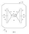
- FIG. 6illustrates a cross sectional view of a turning magnet
- FIG. 7illustrates a cross sectional view of a turning magnet
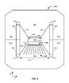
- FIG. 8illustrates magnetic field concentration in a turning magnet
- FIG. 9illustrates correction coils in a turning magnet
- FIG. 10illustrates a magnetic turning section of a synchrotron
- FIG. 11illustrates a magnetic field control system
- FIG. 12presents magnetic field control elements
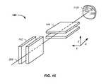
- FIG. 13illustrates magnetic field control elements
- FIG. 14illustrates a charged particle extraction system
- FIG. 15illustrates 3-dimensional scanning of a proton beam focal spot
- FIG. 16illustrates 3-dimensional scanning of a charged particle beam spot.
- This inventionrelates generally to treatment of solid cancers. More particularly, the invention relates to magnetic field control elements used in conjunction with charged particle cancer therapy beam acceleration, extraction, and/or targeting methods and apparatus.
- Novel design features of a synchrotronare described. Particularly, turning or bending magnets, edge focusing magnets, magnetic field concentration magnets, winding and correction coils, flat magnetic filed incident surfaces, and extraction elements are described that minimize the overall size of the synchrotron, provide a tightly controlled proton beam, directly reduce the size of required magnetic fields, directly reduce required operating power, and allow continual acceleration of protons in a synchrotron even during a process of extracting protons from the synchrotron.
- a cyclotronuses a constant magnetic field and a constant-frequency applied electric field. One of the two fields is varied in a synchrocyclotron. Both of these fields are varied in a synchrotron.
- a synchrotronis a particular type of cyclic particle accelerator in which a magnetic field is used to turn the particles so they circulate and an electric field is used to accelerate the particles. The synchrotron carefully synchronizes the applied fields with the travelling particle beam.
- the charged particles pathcan be held constant as they are accelerated.
- Thisallows the vacuum container for the particles to be a large thin torus.
- itis easier to use some straight sections between the bending magnets and some turning sections giving the torus the shape of a round-cornered polygon.
- a path of large effective radiusis thus constructed using simple straight and curved pipe segments, unlike the disc-shaped chamber of the cyclotron type devices.
- the shapealso allows and requires the use of multiple magnets to bend the particle beam.
- the maximum energy that a cyclic accelerator can impartis typically limited by the strength of the magnetic fields and the minimum radius/maximum curvature, of the particle path.
- the maximum radiusis quite limited as the particles start at the center and spiral outward, thus this entire path must be a self-supporting disc-shaped evacuated chamber. Since the radius is limited, the power of the machine becomes limited by the strength of the magnetic field. In the case of an ordinary electromagnet, the field strength is limited by the saturation of the core because when all magnetic domains are aligned the field may not be further increased to any practical extent. The arrangement of the single pair of magnets also limits the economic size of the device.
- Synchrotronsovercome these limitations, using a narrow beam pipe surrounded by much smaller and more tightly focusing magnets.
- the ability of this device to accelerate particlesis limited by the fact that the particles must be charged to be accelerated at all, but charged particles under acceleration emit photons, thereby losing energy.
- the limiting beam energyis reached when the energy lost to the lateral acceleration required to maintain the beam path in a circle equals the energy added each cycle.
- More powerful acceleratorsare built by using large radius paths and by using more numerous and more powerful microwave cavities to accelerate the particle beam between corners. Lighter particles, such as electrons, lose a larger fraction of their energy when turning. Practically speaking, the energy of electron/positron accelerators is limited by this radiation loss, while it does not play a significant role in the dynamics of proton or ion accelerators. The energy of those is limited strictly by the strength of magnets and by the cost.
- a charged particle beam therapy systemsuch as a proton beam, hydrogen ion beam, or carbon ion beam
- the charged particle beam therapy systemis described using a proton beam.
- the aspects taught and described in terms of a proton beamare not intended to be limiting to that of a proton beam and are illustrative of a charged particle beam system. Any charged particle beam system is equally applicable to the techniques described herein.
- the charged particle beampreferably comprises a number of subsystems including any of: a main controller 110 ; an injection system 120 ; a synchrotron 130 that typically includes: (1) an accelerator system 132 and (2) an extraction system 134 ; a targeting/delivery system 140 ; a patient interface module 150 ; a display system 160 ; and/or an imaging system 170 .
- the main controller 110controls one or more of the subsystems to accurately and precisely deliver protons to a tumor of a patient. For example, the main controller 110 obtains an image, such as a portion of a body and/or of a tumor, from the imaging system 170 . The main controller 110 also obtains position and/or timing information from the patient interface module 150 . The main controller 110 then optionally controls the injection system 120 to inject a proton into a synchrotron 130 .
- the synchrotrontypically contains at least an accelerator system 132 and an extraction system 134 .
- the main controllerpreferably controls the proton beam within the accelerator system, such as by controlling speed, trajectory, and timing of the proton beam.
- the main controllerthen controls extraction of a proton beam from the accelerator through the extraction system 134 .
- the controllercontrols timing, energy, and/or intensity of the extracted beam.
- the controller 110also preferably controls targeting of the proton beam through the targeting/delivery system 140 to the patient interface module 150 .
- One or more components of the patient interface module 150are preferably controlled by the main controller 110 .
- display elements of the display system 160are preferably controlled via the main controller 110 . Displays, such as display screens, are typically provided to one or more operators and/or to one or more patients.
- the main controller 110times the delivery of the proton beam from all systems, such that protons are delivered in an optimal therapeutic manner to the patient.
- the main controller 110refers to a single system controlling the charged particle beam system 100 , to a single controller controlling a plurality of subsystems controlling the charged particle beam system 100 , or to a plurality of individual controllers controlling one or more sub-systems of the charged particle beam system 100 .
- synchrotronis used to refer to a system maintaining the charged particle beam in a circulating path; however, cyclotrons are alternatively used, albeit with their inherent limitations of energy, intensity, and extraction control.
- the charged particle beamis referred to herein as circulating along a circulating path about a central point of the synchrotron.
- the circulating pathis alternatively referred to as an orbiting path; however, the orbiting path does not refer a perfect circle or ellipse, rather it refers to cycling of the protons around a central point or region.
- the injection system 120 or ion source or charged particle beam sourcegenerates protons.
- the protonsare delivered into a vacuum tube that runs into, through, and out of the synchrotron.
- the generated protonsare delivered along an initial path 262 .
- Focusing magnets 230such as quadrupole magnets or injection quadrupole magnets, are used to focus the proton beam path.
- a quadrupole magnetis a focusing magnet.
- An injector bending magnet 232bends the proton beam toward the plane of the synchrotron 130 .
- the focused protons having an initial energyare introduced into an injector magnet 240 , which is preferably an injection Lamberson magnet.
- the initial beam path 262is along an axis off of, such as above, a circulating plane of the synchrotron 130 .
- the injector bending magnet 232 and injector magnet 240combine to move the protons into the synchrotron 130 .
- Main bending or turning magnets, dipole magnets, or circulating magnets 250are used to turn the protons along a circulating beam path 264 .
- a dipole magnetis a bending magnet.
- the main bending magnets 250bend the initial beam path 262 into a circulating beam path 264 .
- the main bending magnets 250 or circulating magnetsare represented as four sets of four magnets to maintain the circulating beam path 264 into a stable circulating beam path.
- any number of magnets or sets of magnetsare optionally used to move the protons around a single orbit in the circulation process.
- the protonspass through an accelerator 270 .
- the acceleratoraccelerates the protons in the circulating beam path 264 .
- the fields applied by the magnets 250are increased.
- the speed of the protons achieved by the accelerator 270are synchronized with magnetic fields of the main bending magnets 250 or circulating magnets to maintain stable circulation of the protons about a central point or region 280 of the synchrotron.
- the accelerator 270 /main bending magnet 250 combinationis used to accelerate and/or decelerate the circulating protons while maintaining the protons in the circulating path or orbit.
- An extraction element of the inflector/deflector system 290is used in combination with a Lamberson extraction magnet 292 to remove protons from their circulating beam path 264 within the synchrotron 130 .
- a deflector componentis a Lamberson magnet.
- the deflectormoves the protons from the circulating plane to an axis off of the circulating plane, such as above the circulating plane.
- Extracted protonsare preferably directed and/or focused using an extraction bending magnet 237 and extraction focusing magnets 235 , such as quadrupole magnets along a transport path 268 into the scanning/targeting/delivery system 140 .
- Two components of a scanning system 140 or targeting systemtypically include a first axis control 142 , such as a vertical control, and a second axis control 144 , such as a horizontal control.
- the first axis control 142allows for about 100 mm of vertical or y-axis scanning of the proton beam 268 and the second axis control 144 allows for about 700 mm of horizontal or x-axis scanning of the proton beam 268 .
- a nozzle systemis optionally used for imaging the proton beam and/or as a vacuum barrier between the low pressure beam path of the synchrotron and the atmosphere.
- Protonsare delivered with control to the patient interface module 150 and to a tumor of a patient. All of the above listed elements are optional and may be used in various permutations and combinations. Use of the above listed elements is further described, infra. Protons are delivered with control to the patient interface module 170 and to a tumor of a patient.
- the charged particle irradiationincludes a synchrotron having: a center, straight sections, and turning sections.
- the charged particle beam pathruns about the center, through the straight sections, and through the turning sections, where each of the turning sections comprises a plurality of bending magnets.
- the circulation beam pathcomprises a length of less than sixty meters, and the number of straight sections equals the number of turning sections.
- no quadrupolesare used in or around the circulating path of the synchrotron.
- a synchrotron 130preferably comprises a combination of straight sections 310 and ion beam turning sections 320 .
- the circulating path of the protonsis not circular in a synchrotron, but is rather a polygon with rounded corners.
- the synchrotron 130which is also referred to as an accelerator system, has four straight elements and four turning sections.
- straight sections 310include the: inflector 240 , accelerator 270 , extraction system 290 , and deflector 292 .
- ion beam turning sections 320which are also referred to as magnet sections or turning sections. Turning sections are further described, infra.
- the synchrotron 130comprises four straight sections 310 and four turning sections 320 where each of the four turning sections use one or more magnets to turn the proton beam about ninety degrees.
- the ability to closely space the turning sections and efficiently turn the proton beamresults in shorter straight sections. Shorter straight sections allows for a synchrotron design without the use of focusing quadrupoles in the circulating beam path of the synchrotron.
- the illustrated synchrotronhas about a five meter diameter versus eight meter and larger cross sectional diameters for systems using a quadrupole focusing magnet in the circulating proton beam path.
- Each of the turning sectionspreferably comprises multiple magnets, such as about 2, 4, 6, 8, 10, or 12 magnets.
- four turning magnets 410 , 420 , 430 , 440 in the first turning section 320are used to illustrate key principles, which are the same regardless of the number of magnets in a turning section 320 .
- a turning magnet 410is a particular type of circulating magnet 250 .
- the Lorentz forceis the force on a point charge due to electromagnetic fields.
- Equation 1F is the force in newtons; B is the magnetic field in Teslas; and v is the instantaneous velocity of the particles in meters per second.
- the turning sectionincludes a gap 510 .
- the charged particlesrun through the gap.
- the gapis a section of a charged particle beam path through which charged particles are accelerated in the synchrotron 130 .
- the gapis preferably a flat gap, allowing for a magnetic field across the gap that is more uniform, even, and intense.
- a magnetic fieldenters the gap through a magnetic field incident surface and exits the gap through a magnetic field exiting surface.
- the gap 510runs in a vacuum tube between two magnets or between two magnet halves.
- the gapis controlled by at least two parameters: (1) the gap 510 is kept as large as possible to minimize loss of protons and (2) the gap 510 is kept as small as possible to minimize magnet sizes and the associated size and power requirements of the magnet power supplies.
- the flat nature of the gap 510allows for a compressed and more uniform magnetic field across the gap.
- the gappreferably has a first dimension of less than about three centimeters and a second dimension of less than about eight centimeters.
- One example of a gap dimensionis to accommodate a vertical proton beam size of about 2 cm with a horizontal beam size of about 5 to 6 cm.
- a larger gap sizerequires a larger power supply. For instance, if the gap size doubles in vertical size, then the power supply requirements increase by about a factor of four.
- the flatness of the gapis also important. For example, the flat nature of the gap allows for an increase in energy of the extracted protons from about 250 to about 330 MeV. More particularly, if the gap 510 has an extremely flat surface, then the limits of a magnetic field of an iron magnet are reachable.
- An exemplary precision of the flat surface of the gap 510is a polish of less than about five microns and preferably with a polish of about one to three microns. Unevenness in the surface results in imperfections in the applied magnetic field. The polished flat surface spreads unevenness of the applied magnetic field.
- the charged particle beammoves through the gap with an instantaneous velocity, v.
- a first magnetic coil 520 and a second magnetic coil 530run above and below the gap 510 , respectively.
- Current running through the coils 520 , 530results in a magnetic field, B, running through the single magnet turning section 410 .
- the magnetic field, Bruns upward, which results in a force, F, pushing the charged particle beam inward toward a central point of the synchrotron, which turns the charged particle beam in an arc.
- the coils 520 , 530typically have return elements or turns at the end of one magnet, such as at the end of the first magnet turning section 410 .
- the return elementstake space.
- the spacereduces the percentage of the path about one orbit of the synchrotron that is covered by the turning magnets. This leads to portions of the circulating path where the protons are not turned and/or focused and allows for portions of the circulating path where the proton path defocuses. Thus, the space results in a larger synchrotron. Therefore, the space between magnet turning sections 560 is preferably minimized.
- the second turning magnetis used to illustrate that the coils 520 , 530 optionally run along a plurality of magnets, such as 2, 3, 4, 5, 6, or more magnets. Coils 520 , 530 running across turning section magnets allows for two turning section magnets to be spatially positioned closer to each other due to the removal of the steric constraint of the turns, which reduces and/or minimizes the space 560 between two turning section magnets.
- the magnet assemblyhas a first magnet section or half 610 and a second magnet section or half 620 .
- a magnetic field induced by coils, described infraruns between the first magnet section 610 to the second magnet section 620 across the gap 510 .
- the gap 510includes a magnetic field incident surface 670 and a magnetic field exiting surface 680 .
- Return magnetic fieldsrun through a first yoke 612 and second yoke 622 .
- the charged particlesrun through the vacuum tube in the gap. As illustrated, protons run into FIG.
- the magnetic fieldis created using windings through which a current flows about the core.
- a first coilmakes up and a second coil makes up a second winding coil 660 .
- Isolating gaps 630 , 640such as air gaps, isolate the iron based yokes 612 , 622 from the gap 510 .
- the gapis approximately flat to yield a uniform magnetic field across the gap, as described supra.
- the ends of a single turning magnetare preferably beveled.
- Nearly perpendicular or right angle edges of a turning magnet 410are represented by a dashed lines 674 , 684 .
- the edge of the turning magnetis beveled at angles alpha, ⁇ , and beta, ⁇ , which is the off perpendicular angle between the right angles 674 , 684 and beveled edges 672 , 682 .
- the angle alphais used to describe the effect and the description of angle alpha applies to angle beta, but angle alpha is optionally different from angle beta.
- the angle alphaprovides an edge focusing effect. Beveling the edge of the turning magnet 410 at angle alpha focuses the proton beam.
- Multiple turning magnetsprovide multiple magnet edges that each have edge focusing effects in the synchrotron 310 . If only one turning magnet is used, then the beam is only focused once for angle alpha or twice for angle alpha and angle beta. However, by using smaller turning magnets, more turning magnets fit into the turning sections 320 of the synchrotron 310 . For example, if four magnets are used in a turning section 320 of the synchrotron, then there are eight possible edge focusing effect surfaces, two edges per magnet. The eight focusing surfaces yield a smaller cross sectional beam size. This allows the use of a smaller gap 510 .
- edge focusing effects in the turning magnetsresults in not only a smaller gap, but also the use of smaller magnets and smaller power supplies.
- a synchrotron 310 having four turning sections 320 where each turning sections has four turning magnets and each turning magnet has two focusing edgesa total of thirty-two focusing edges exist for each orbit of the protons in the circulating path of the synchrotron 310 .
- 2, 6, or 8 magnetsare used in a given turning section, or if 2, 3, 5, or 6 turning sections are used, then the number of edge focusing surfaces expands or contracts according to equation 2.
- TFENTS * M NTS * FE M eq . ⁇ 2
- TFEis the number of total focusing edges
- NTSis the number of turning section
- Mis the number of magnets
- FEis the number of focusing edges.
- the inventorshave determined that multiple smaller magnets have benefits over fewer larger magnets. For example, the use of 16 small magnets yields 32 focusing edges whereas the use of 4 larger magnets yields only 8 focusing edges.
- the use of a synchrotron having more focusing edgesresults in a circulating path of the synchrotron built without the use of focusing quadrupoles magnets. All prior art synchrotrons use quadrupoles in the circulating path of the synchrotron. Further, the use of quadrupoles in the circulating path necessitates additional straight sections in the circulating path of the synchrotron. Thus, the use of quadrupoles in the circulating path of a synchrotron results in synchrotrons having larger diameters or larger circumferences.
- the synchrotronhas:
- the incident magnetic field surface 670 of the first magnet section 610is further described.
- FIG. 6is not to scale and is illustrative in nature. Local imperfections or unevenness in quality of the finish of the incident surface 670 results in inhomogeneities or imperfections in the magnetic field applied to the gap 510 .
- the incident surface 670is flat, such as to within about a zero to three micron finish polish, or less preferably to about a ten micron finish polish.
- the first magnet section 610preferably contains an initial cross sectional distance 810 of the iron based core.
- the contours of the magnetic fieldare shaped by the magnets 610 , 620 and the yokes 612 , 622 .
- the iron based coretapers to a second cross sectional distance 820 .
- the magnetic field in the magnetpreferentially stays in the iron based core as opposed to the gaps 630 , 640 .
- the magnetic fieldconcentrates.
- the change in shape of the magnet from the longer distance 810 to the smaller distance 820acts as an amplifier.
- the concentration of the magnetic fieldis illustrated by representing an initial density of magnetic field vectors 830 in the initial cross section 810 to a concentrated density of magnetic field vectors 840 in the final cross section 820 .
- the concentration of the magnetic field due to the geometry of the turning magnetsresults in fewer winding coils 650 , 660 being required and also a smaller power supply to the coils being required.
- the initial cross-section distance 810is about fifteen centimeters and the final cross-section distance 820 is about ten centimeters.
- the concentration of the magnetic fieldis about 15/10 or 1.5 times at the incident surface 670 of the gap 510 , though the relationship is not linear.
- the taper 860has a slope, such as about 20 to 60 degrees.
- the concentration of the magnetic fieldsuch as by 1.5 times, leads to a corresponding decrease in power consumption requirements to the magnets.
- the first magnet section 610preferably contains an initial cross sectional distance 810 of the iron based core.
- the contours of the magnetic fieldare shaped by the magnet sections 610 , 620 and the yokes 612 , 622 .
- the coretapers to a second cross sectional distance 820 with a smaller angle theta, ⁇ .
- the magnetic field in the magnetpreferentially stays in the iron based core as opposed to the gaps 630 , 640 .
- the magnetic fieldconcentrates.
- the smaller angle, thetaresults in a greater amplification of the magnetic field in going from the longer distance 810 to the smaller distance 820 .
- the concentration of the magnetic fieldis illustrated by representing an initial density of magnetic field vectors 830 in the initial cross section 810 to a concentrated density of magnetic field vectors 840 in the final cross section 820 .
- the concentration of the magnetic field due to the geometry of the turning magnetsresults in fewer winding coils 650 , 660 being required and also a smaller power supply to the winding coils 650 , 660 being required.
- optional correction coils 910 , 920are illustrated that are used to correct the strength of one or more turning magnets.
- the correction coils 920 , 930supplement the winding coils 650 , 660 .
- the correction coils 910 , 920have correction coil power supplies that are separate from winding coil power supplies used with the winding coils 650 , 660 .
- the correction coil power suppliestypically operate at a fraction of the power required compared to the winding coil power supplies, such as about 1, 2, 3, 5, 7, or 10 percent of the power and more preferably about 1 or 2 percent of the power used with the winding coils 650 , 660 .
- the smaller operating power applied to the correction coils 920 , 920allows for more accurate and/or precise control of the correction coils.
- the correction coilsare used to adjust for imperfection in the turning magnets 410 , 420 , 430 , 440 .
- the winding coilspreferably cover 1, 2, or 4 turning magnets.
- a winding coil 1030winds around two turning magnets 410 , 420 .
- Correction coilsare used to correct the magnetic field strength of one or more turning or bending magnets.
- a first correction coil 1010corrects a single turning magnet.
- a second correction coil 1020corrects two turning magnets 410 , 420 .
- the correction coilssupplement the winding coils.
- the correction coilshave correction coil power supplies that are separate from winding coil power supplies used with the winding coils.
- the correction coil power suppliestypically operate at a fraction of the power required compared to the winding coil power supplies, such as about 1, 2, 3, 5, 7, or 10 percent of the power and more preferably about 1 or 2 percent of the power used with the winding coils.
- the smaller operating power applied to the correction coilsallows for more accurate and/or precise control of the correction coils.
- a magnetic field produced by the first correction coil 1010is used to adjust for imperfection in a magnetic filed produced by the turning magnet 410 or the second correction coil 1020 is used to adjust for imperfection in the turning magnet sections 610 , 620 .
- separate correction coilsare used for each turning magnet allowing individual tuning of the magnetic field for each turning magnet, which eases quality requirements in the manufacture of each turning magnet.
- Correction coilsare preferably used in combination with magnetic field concentration magnets to stabilize a magnetic field in a synchrotron.
- high precision magnetic field sensors 1050are used to sense a magnetic field created in one or more turning magnets using winding elements.
- the sensed magnetic fieldis sent via a feedback loop to a magnetic field controller that adjusts power supplied to correction coils.
- the correction coilsoperating at a lower power, are capable of rapid adjustment to a new power level.
- the total magnetic field applied by the turning magnets and correction coilsis rapidly adjusted to a new strength, allowing continuous adjustment of the energy of the proton beam.
- a novel extraction systemallows the continuously adjustable energy level of the proton beam to be extracted from the synchrotron.
- one or more high precision magnetic field sensors 1050are placed into the synchrotron and are used to measure the magnetic field at or near the proton beam path.
- the magnetic sensorsare optionally placed between turning magnets and/or within a turning magnet, such as at or near the gap 510 or at or near the magnet core or yoke.
- the sensorsare part of a feedback system to the correction coils, which is optionally run by the main controller 110 .
- the feedback systemis controlled by the main controller 110 or a subunit or sub-function of the main controller 110 .
- the systempreferably stabilizes the magnetic field in the synchrotron elements rather than stabilizing the current applied to the magnets. Stabilization of the magnetic field allows the synchrotron to come to a new energy level quickly.
- the one or more high precision magnetic field sensorsare used to coordinate synchrotron beam energy and timing with patient respiration. Stabilization of the magnetic field allows the synchrotron to come to a new energy level quickly. This allows the system to be controlled to an operator or algorithm selected energy level with each pulse of the synchrotron and/or with each breath of the patient.
- the winding and/or correction coilscorrect 1, 2, 3, or 4 turning magnets, and preferably correct a magnetic field generated by two turning magnets.
- a winding or correction coil covering multiple magnetsreduces space between magnets as fewer winding or correction coil ends are required, which occupy space.
- a respiratory sensor 1110senses the breathing cycle of the subject.
- the respiratory sensorsends the information to an algorithm in a magnetic field controller 1120 , typically via the patient interface module 150 and/or via the main controller 110 or a subcomponent thereof.
- the algorithmpredicts and/or measures when the subject is at a particular point in the breathing cycle, such as at the bottom of a breath.
- Magnetic field sensors 1130such as the high precision magnetic field sensor 1050 , are used as input to the magnetic field controller, which controls a magnet power supply 1140 for a given magnetic field 1150 , such as within a first turning magnet 410 of a synchrotron 130 .
- the control feedback loopis thus used to dial the synchrotron to a selected energy level and deliver protons with the desired energy at a selected point in time, such as at the bottom of the breath. More particularly, the synchrotron accelerates the protons and the control feedback loop keeps the protons in the circulating path by synchronously adjusting the magnetic field strength of the turning magnets. Intensity of the proton beam is also selectable at this stage.
- the feedback control to the correction coilsallows rapid selection of energy levels of the synchrotron that are tied to the patient's breathing cycle. This system is in stark contrast to a system where the current is stabilized and the synchrotron deliver pulses with a period, such as 10 or 20 cycles second with a fixed period.
- the feedback or the magnetic field design coupled with the correction coilsallows for the extraction cycle to match the varying respiratory rate of the patient.
- FIG. 10an example of a winding coil 1030 that covers four turning magnets 410 , 420 , 430 , 440 is provided. As described, supra, this system reduces space between turning section allowing more magnetic field to be applied per radian of turn.
- a first correction coil 1010is illustrated that is used to correct the magnetic field for the first turning magnet 410 . Individual correction coils for each turning magnet are preferred and individual correction coils yield the most precise and/or accurate magnetic field in each turning section. Particularly, the individual correction coil 1010 is used to compensate for imperfections in the individual magnet of a given turning section.
- corresponding magnetic fieldsare individually adjustable in a series of feedback loops, via a magnetic field monitoring system 1030 , as an independent coil is used for each turning section magnet.
- a multiple magnet correction coil 1020is used to correct the magnetic field for a plurality of turning section magnets.
- FIGS. 12 and 13are not to scale and are illustrative in nature.
- FIGS. 12 and 13are in an exploded view for clarity; the described layers are preferably joined or compressed together in the final apparatus and in use.
- the magnetic field incident surface 670 of the first magnet, magnet half, or magnet section 610is further described.
- the first magnet 610terminates next to the gap 510 , through which the protons circulate.
- the flatness of the magnetic field incident surfaceis described. Imperfections in the surface quality of the magnetic field incident surface 670 of the first magnet 610 results in non-uniformity in the magnetic field across the gap 510 . Imperfections in the magnetic field results in variations in control of the protons in the circulating path of the synchrotron. Poor control of protons in their circulating path results in defocused protons not fitting into a small gap 510 . Hence, the gap size must be increased.
- gap surfaceis described in terms of the first turning magnet 610 , the discussion applies to each of the turning magnets in the synchrotron.
- gap 510 surfaceis described in terms of the magnetic field incident surface 670 , the discussion additionally optionally applies to the magnetic field exiting surface 680 .
- Several examplesillustrate how desired flatness specifications are achieved.
- the magnetic field incident surface 670 of the first magnet 610is machined flat, such as to within about a zero to three micron finish polish or less preferably to about a ten micron finish polish.
- the cost of machining the surface to the tighter zero to three micron finish roughnessis prohibitive to large scale production as the cost is high per synchrotron unit as each magnetic field incident, and optionally exiting, surface of each turning magnet of each synchrotron unit would have to be machined.
- the costs of machining a large piece of magnetically uniform materialcan reach $100,000 per piece, which is prohibitive to production.
- a first layeris a gap isolating material, which is preferably about one millimeter in thickness and is more preferably about one-half millimeter in thickness.
- the gap isolating material 1210is preferably a non-conductive electric isolating layer.
- the gap isolating material 1210is especially non-magnetic.
- the gap isolating material 1210preferably has a surface finish of about zero to three microns.
- a second layeris preferably a first magnetic penetration layer 1220 .
- the first magnetic penetration layer 1220is preferably composed of a very thin piece of foil, such as about 0.1 mm thick.
- the first magnetic penetration layer 1220has an inner surface and an outer surface.
- the foilis preferably a nickel alloy, a special steel, or iron.
- the foilis especially smooth, such as to about zero to three micron polish finish on both sides.
- a first adhesive layer 1215 and second adhesive layer 1225are a glue or bonding agent.
- the first adhesive layer 1215 and second adhesive layer 1225are optionally composed of the same material or are different materials.
- the adhesive layers 1215 , 1225primary purpose is to connect the gap isolating material 1210 and first magnetic penetration layer 1220 to the magnet 610 .
- a compression forcecompresses together the inner surface of the first magnetic penetration layer 1220 , the second adhesive layer 1225 , the gap isolating material 1210 , the first adhesive layer 1215 , and the magnetic field incident surface 670 of the first magnet 610 .
- the resultis a new outer layer of the first magnet 610 , which is the outer surface of the first magnetic penetration layer.
- the outer surface of the first magnetic penetration layerhas a surface finish of about zero to three microns of roughness and is preferably electrically isolated from the first magnet 610 .
- the outer surface of the first magnetic penetration layer 1220preferably defines the surface of the gap 510 . When more than one magnetic penetration layer is used, the magnetic penetration surface most remove from the first magnet 610 defines the edge of the gap 510 .
- the gap isolating material 1210 and flat outer surface of the first magnetic penetration layer 1220improve the magnetic field properties of the applied magnetic field across the gap 510 .
- iron in the magnet 610has its own magnetic properties and iron has non-uniform properties. Instead of trying to make the iron uniform or using very expensive material for the magnet 610 , the series of layers is used to make the magnetic field more uniform.
- the gap isolating material 1210isolates residual magnetic properties of the magnet 610 .
- the gap isolating material 1210does not stop the magnetic properties of the magnet, but rather the isolating material enhances uniformity of the magnetic field in the gap 510 and makes the field more stable.
- the gap isolating material 1210does not actually stop the magnetic properties of the magnet 610 from reaching the gap 510 . Instead, the gap isolating material 1220 isolates and evens out the non-uniform properties of the iron core of the magnet 610 . Essentially, the iron of the first magnet has its own magnetic properties and on a micro level is not uniform. The gap isolating material 1210 yields a distance to blend the imperfections in the magnetic field resulting from the iron inhomogeneities and yields a more stable and uniform magnetic field across the gap.
- the first magnetic penetration layer 1220by being a very flat and high penetration material, spreads the unevenness of the applied magnetic field across the gap 510 . Again, having a very flat and high penetration magnetic material next to the gap creates a uniform magnetic field across the gap, which leads to a smaller required gap, smaller required magnetic fields, and smaller required power supplies, as described supra.
- a second magnetic penetration layer 1330is added to the first magnetic penetration layer 1220 and the gap isolating material 1210 and the thicknesses of the layers are changed.
- the gap isolating material 1210retains the above described properties, but is preferably about one-quarter millimeter in thickness.
- the first magnetic penetration layer 1220retains the same properties as described, supra.
- a second magnetic penetration layer 1330is similar to or the same as the first magnetic penetration layer 1220 .
- the first adhesive layer 1215 , second adhesive layer 1225 , and third adhesive layer 1335are a glue or bonding agent.
- the second magnetic penetration layer 1330is joined to the first magnetic penetration layer 1220 via the third adhesive layer 1335 .
- the first magnetic penetration material layer 1220is joined to the gap isolating material 1210 with the second adhesive layer 1225 .
- the gap isolating materialis joined to the magnetic field incident surface 670 of the first magnet 610 with the first adhesive layer 1215 .
- the resultis a new outer layer of the first magnet 610 , which is the outer surface of the second magnetic penetration layer 1330 .
- the use of multiple magnetic field penetration layersresults in a flatter resulting outer surface of the first magnet 610 when the initial outer surface of the first magnet includes surface imperfections as the imperfections are reduced with each subsequently bonded layer.
- the synchrotronincludes: a first magnet having an incident surface, a non-magnetic isolating layer having a first side and a second side, a first magnetic penetration layer or foil having an inner surface and an outer surface, and/or a second magnet having an exiting surface.
- the incident surface of the first magnetaffixes directly or indirectly to the first side of said isolating layer and the second side of said isolating layer affixes directly or indirectly to the inner surface of the first foil, where the charged particle beam path is positioned between the outer surface of the first foil and the exiting surface.
- the synchrotronfurther includes a second magnetic penetration layer or second foil having an inner side and an outer side where the inner side of the second foil affixes directly or indirectly to the outer surface of the first foil.
- the synchrotronuses a magnetic field to turn or bend the charged particles running in the charged particle beam path.
- the magnetic fieldruns through any of the first magnet, the non-conductive isolating layer, the first magnetic penetration layer, the second magnetic penetration layer, the charged particle beam path, the second magnet, the yoke, and back to the first magnet.
- the magnetic field of the first magnetis blend out in the thickness of the non-magnetic isolating layer resulting in an evening of the non-uniform properties of the magnetic field in the first magnet.
- the first and/or second magnetic penetration layersmooth out the incident surface of the first magnet.
- the high surface polish of the first and/or second magnetic penetration layerresults in an even magnetic field running axially across the charged particle beam path and/or gap.
- the application of one or more isolation layers and/or one or more magnetic field penetration layersresults in a magnetic surface with a surface polish that is finer that the surface polish of the incident surface of the first magnet.
- the incident surface of the first magnethas a surface roughness greater than a surface roughness of the outer surface of the outermost magnetic penetration layer next to the gap and/or charged particle beam path.
- the second magnetic penetration layer 1210is not necessarily the same material or thickness as the first magnetic penetration layer 1220 .
- One or more magnetic penetration layersare optionally used without use of a gap isolating material.
- a gap isolating layeris optionally used without use of a magnetic penetration layer.
- Zero or more than one gap isolating material layeris optionally used.
- More than two magnetic penetration layersare optionally used, such as 3, 4, 5, 7, or 10 layers.
- the adhesive layersare optionally composed of the same material or are different materials.
- a smaller gap 510 sizerequires a higher quality finish.
- the combination of the highly polished magnetic penetration layer and the magnetic field gap isolating material having a polished surface onto the magnetresults in an outer magnet layer that is very flat.
- the very flat surfacesuch as 0-3 micron finish, allows for a smaller gap size, a smaller applied magnetic field, smaller power supplies, and tighter control of the proton beam cross-sectional area.
- FIG. 14an exemplary proton extraction process from the synchrotron 130 is illustrated.
- FIG. 14removes elements represented in FIG. 2 , such as the turning magnets, which allows for greater clarity of presentation of the proton beam path as a function of time.
- protonsare extracted from the synchrotron 130 by slowing the protons.
- the protonswere initially accelerated in a circulating path 264 , which is maintained with a plurality of turning magnets 250 .
- the circulating pathis referred to herein as an original central beamline 264 .
- the protonsrepeatedly cycle around a central point in the synchrotron 280 .
- the proton pathtraverses through an RF cavity system 1410 .
- an RF fieldis applied across a first blade 1412 and a second blade 1414 , in the RF cavity system 1410 .
- the first blade 1412 and second blade 1414are referred to herein as a first pair of blades.
- an RF voltageis applied across the first pair of blades, where the first blade 1412 of the first pair of blades is on one side of the circulating proton beam path 264 and the second blade 1414 of the first pair of blades is on an opposite side of the circulating proton beam path 264 .
- the applied RF fieldapplies energy to the circulating charged-particle beam.
- the applied RF fieldalters the orbiting or circulating beam path slightly of the protons from the original central beamline 264 to an altered circulating beam path 265 .
- the RF fieldfurther moves the protons off of the original proton beamline 264 .
- the altered beamlineis slightly elliptical.
- the applied RF fieldis timed to apply outward or inward movement to a given band of protons circulating in the synchrotron accelerator.
- Each orbit of the protonsis slightly more off axis compared to the original circulating beam path 264 .
- Successive passes of the protons through the RF cavity systemare forced further and further from the original central beamline 264 by altering the direction and/or intensity of the RF field with each successive pass of the proton beam through the RF field.
- the RF voltageis frequency modulated at a frequency about equal to the period of one proton cycling around the synchrotron for one revolution or at a frequency than is an integral multiplier of the period of one proton cycling about the synchrotron.
- the applied RF frequency modulated voltageexcites a betatron oscillation.
- the oscillationis a sine wave motion of the protons.
- the process of timing the RF field to a given proton beam within the RF cavity systemis repeated thousands of times with successive passes of the protons being moved approximately one micrometer further off of the original central beamline 264 . For clarity, the effect of the approximately 1000 changing beam paths with each successive path of a given band of protons through the RF field are illustrated as the altered beam path 265 .
- the altered circulating beam path 265touches a material 1430 , such as a foil or a sheet of foil.
- the foilis preferably a lightweight material, such as beryllium, a lithium hydride, a carbon sheet, or a material of low nuclear charge.
- a material of low nuclear chargeis a material composed of atoms consisting essentially of atoms having six or fewer protons.
- the foilis preferably about 10 to 150 microns thick, is more preferably 30 to 100 microns thick, and is still more preferably 40 to 60 microns thick. In one example, the foil is beryllium with a thickness of about 50 microns.
- the reduced radius of curvature 266 pathis also referred to herein as a path having a smaller diameter of trajectory or a path having protons with reduced energy.
- the reduced radius of curvature 266is typically about two millimeters less than a radius of curvature of the last pass of the protons along the altered proton beam path 265 .
- the thickness of the material 1430is optionally adjusted to created a change in the radius of curvature, such as about 1 ⁇ 2, 1, 2, 3, or 4 mm less than the last pass of the protons 265 or original radius of curvature 264 .
- Protons moving with the smaller radius of curvaturetravel between a second pair of blades.
- the second pair of bladesis physically distinct and/or are separated from the first pair of blades.
- one of the first pair of bladesis also a member of the second pair of blades.
- the second pair of bladesis the second blade 1414 and a third blade 1416 in the RF cavity system 1410 .
- a high voltage DC signalsuch as about 1 to 5 kV, is then applied across the second pair of blades, which directs the protons out of the synchrotron through a deflector 292 , such as a Lamberson magnet, into a transport path 268 .
- Control of acceleration of the charged particle beam path in the synchrotron with the accelerator and/or applied fields of the turning magnets in combination with the above described extraction systemallows for control of the intensity of the extracted proton beam, where intensity is a proton flux per unit time or the number of protons extracted as a function of time. For example, when a current is measured beyond a threshold, the RF field modulation in the RF cavity system is terminated or reinitiated to establish a subsequent cycle of proton beam extraction. This process is repeated to yield many cycles of proton beam extraction from the synchrotron accelerator.
- the benefits of the systeminclude a multi-dimensional scanning system.
- the systemallows an energy and/or intensity change while scanning.
- the extraction systemdoes not depend on any change any change in magnetic field properties, it allows the synchrotron to continue to operate in acceleration or deceleration mode during the extraction process. Stated differently, the extraction process does not interfere with synchrotron.
- traditional extraction systemsintroduce a new magnetic field, such as via a hexapole, during the extraction process. More particularly, traditional synchrotrons have a magnet, such as a hexapole magnet, that is off during an acceleration stage. During the extraction phase, the hexapole magnetic field is introduced to the circulating path of the synchrotron. The introduction of the magnetic field necessitates two distinct modes, an acceleration mode and an extraction mode, which are mutually exclusive in time.
- FIG. 15a beam delivery and tissue volume scanning system is illustrated.
- the worldwide radiotherapy communityuses a method of dose field forming using a pencil beam scanning system.
- FIG. 15illustrates a spot scanning system or tissue volume scanning system.
- the proton beamis controlled, in terms of transportation and distribution, using an inexpensive and precise scanning system.
- the scanning systemis an active system, where the beam is focused into a spot focal point of about one-half, one, two, or three millimeters in diameter.
- the focal pointis translated along two axes while simultaneously altering the applied energy of the proton beam, which effectively changes the third dimension of the focal point.
- FIG. 15a beam delivery and tissue volume scanning system is illustrated.
- the spotis translated up a vertical axis, is moved horizontally, and is then translated down a vertical axis.
- currentis used to control a vertical scanning system having at least one magnet.
- the applied currentalters the magnetic field of the vertical scanning system to control the vertical deflection of the proton beam.
- a horizontal scanning magnet systemcontrols the horizontal deflection of the proton beam.
- the degree of transport along each axesis controlled to conform to the tumor cross-section at the given depth.
- the depthis controlled by changing the energy of the proton beam. For example, the proton beam energy is decreased, so as to define a new penetration depth, and the scanning process is repeated along the horizontal and vertical axes covering a new cross-sectional area of the tumor.
- the three axes of controlallow scanning or movement of the proton beam focal point over the entire volume of the cancerous tumor.
- the time at each spot and the direction into the body for each spotis controlled to yield the desired radiation does at each sub-volume of the cancerous volume while distributing energy hitting outside of the tumor.
- the focused beam spot volume dimensionis preferably tightly controlled to a diameter of about 0.5, 1, or 2 millimeters, but is alternatively several centimeters in diameter.
- Preferred design controlsallow scanning in two directions with: (1) a vertical amplitude of about 100 mm amplitude and frequency up to 200 Hz; and (2) a horizontal amplitude of about 700 mm amplitude and frequency up to 1 Hz. More or less amplitude in each axis is possible by altering the scanning magnet systems.
- the proton beamgoes along a z-axis controlled by the beam energy, the horizontal movement is along an x-axis, and the vertical direction is along a y-axis.
- the distance the protons move along the z-axis into the tissue, in this example,is controlled by the kinetic energy of the proton.
- This coordinate systemis arbitrary and exemplary.
- the actual control of the proton beamis controlled in 3-dimensional space using two scanning magnet systems and by controlling the kinetic energy of the proton beam.
- the use of the extraction system, described supra,allows for different scanning patterns. Particularly, the system allows simultaneous adjustment of the x-, y-, and z-axes in the irradiation of the solid tumor.
- the systemallows for moving along the z-axes while simultaneously adjusting the x- and or y-axes.
- the tumoris optionally irradiated in three simultaneous dimensions. For example, the tumor is irradiated around an outer edge of the tumor in three dimensions. Then the tumor is irradiated around an outer edge of an internal section of the tumor. This process is repeated until the entire tumor is irradiated.
- the outer edge irradiationis preferably coupled with simultaneous rotation of the subject, such as about a vertical y-axis. This system allows for maximum efficiency of deposition of protons to the tumor, as defined using the Bragg peak, to the tumor itself with minimal delivery of proton energy to surrounding healthy tissue.
- the systemallows for multi-axes control of the charged particle beam system in a small space with low power supply.
- the systemuses multiple magnets where each magnet has at least one edge focusing effect in each turning section of the synchrotron and/or multiple magnets having concentrating magnetic field geometry, as described supra.
- the multiple edge focusing effects in the circulating beam path of the synchrotron combined with the concentration geometry of the magnets and described extraction systemyields a synchrotron having:
- the resultis a 3-dimensional scanning system, x-, y-, and z-axes control, where the z-axes control resides in the synchrotron and where the z-axes energy is variably controlled during the extraction process inside the synchrotron.
- FIG. 16an example of a targeting system 140 used to direct the protons to the tumor with 3-dimensional scanning control is provided, where the 3-dimensional scanning control is along the x-, y-, and z-axes.
- the 3-dimensional scanning controlis along the x-, y-, and z-axes.
- charged particles traveling along the transport path 268are directed through a first axis control element 142 , such as a vertical control, and a second axis control element 144 , such as a horizontal control and into a tumor 1101 .
- the extraction systemalso allows for simultaneous variation in the z-axis.
- all three dimensions defining the targeting spot of the proton delivery in the tumorare simultaneously variable.
- the simultaneous variation of the proton delivery spotis illustrated in FIG. 16 by the spot delivery path 269 .
- the protonsare initially directed around an outer edge of the tumor and are then directed around an inner radius of the tumor.
- a multi-field illumination processis used where a not yet irradiated portion of the tumor is preferably irradiated at the further distance of the tumor from the proton entry point into the body. This yields the greatest percentage of the proton delivery, as defined by the Bragg peak, into the tumor and minimizes damage to peripheral healthy tissue.
- delivery of a proton beam dosageis synchronized with a breathing pattern of a subject.
- a subjectalso referred to herein as a patient
- a subjectis breathing many portions of the body move with each breath.
- the lungsmove as do relative positions of organs within the body, such as the stomach, kidneys, liver, chest muscles, skin, heart, and lungs.
- most or all parts of the torsomove with each breath.
- Motionis to be considered in delivery of a proton dose to the body as the protons are preferentially delivered to the tumor and not to surrounding tissue. Motion thus results in an ambiguity in where the tumor resides relative to the beam path.
- protonsare preferentially delivered at the same point in a breathing cycle.
- a rhythmic pattern of breathing of a subjectis determined.
- the cycleis observed or measured.
- a proton beam operatorcan observe when a subject is breathing or is between breaths and can time the delivery of the protons to a given period of each breath.
- the subjectis told to inhale, exhale, and/or hold their breath and the protons are delivered during the commanded time period.
- one or more sensorsare used to determine the breathing cycle of the individual.
- a breath monitoring sensorsenses air flow by or through the mouth or nose.
- Another optional sensoris a chest motion sensor attached or affixed to a torso of the subject.
- a signalis optionally delivered to the subject to more precisely control the breathing frequency.
- a display screenis placed in front of the subject directing the subject when to hold their breath and when to breath.
- a breathing control moduleuses input from one or more of the breathing sensors. For example, the input is used to determine when the next breath exhale is to complete.
- the control moduledisplays a hold breath signal to the subject, such as on a monitor, via an oral signal, digitized and automatically generated voice command, or via a visual control signal.
- a display monitoris positioned in front of the subject and the display monitor displays at least breathing commands to the subject.
- the subjectis directed to hold their breath for a short period of time, such as about one-half, one, two, or three seconds.
- the period of time the subject is asked to hold their breathis less than about ten seconds as the period of time the breath is held is synchronized to the delivery time of the proton beam to the tumor, which is about one-half, one, two, or three seconds.
- protonsare optionally delivered at any point in the breathing cycle, such as upon full inhalation.
- the breathing control moduleDelivery at the top of the breath or when the patient is directed to inhale deeply and hold their breath by the breathing control module is optionally performed as at the top of the breath the chest cavity is largest and for some tumors the distance between the tumor and surrounding tissue is maximized or the surrounding tissue is rarefied as a result of the increased volume. Hence, protons hitting surrounding tissue is minimized.
- the display screentells the subject when they are about to be asked to hold their breath, such as with a 3, 2, 1, second countdown so that the subject is aware of the task they are about to be asked to perform.
- a proton delivery control algorithmis used to synchronize delivery of the protons to the tumor within a given period of each breath, such as at the bottom of a breath when the subject is holding their breath.
- the proton delivery control algorithmis preferably integrated with the breathing control module.
- the proton delivery control algorithmknows when the subject is breathing, where in the breath cycle the subject is, and/or when the subject is holding their breath.
- the proton delivery control algorithmcontrols when protons are injected and/or inflected into the synchrotron, when an RF signal is applied to induce an oscillation, as described supra, and when a DC voltage is applied to extract protons from the synchrotron, as described supra.
- the proton delivery control algorithminitiates proton inflection and subsequent RF induced oscillation before the subject is directed to hold their breath or before the identified period of the breathing cycle selected for a proton delivery time.
- the proton delivery control algorithmcan deliver protons at a selected period of the breathing cycle by simultaneously or near simultaneously delivering the high DC voltage to the second pair of plates, described supra, that results in extraction of the protons from the synchrotron and subsequent delivery to the subject at the selected time point. Since the period of acceleration of protons in the synchrotron is constant, the proton delivery control algorithm is used to set an AC RF signal that matches the breathing cycle or directed breathing cycle of the subject.
- the 3-dimensional scanning system of the proton spot focal pointis preferably combined with a rotation/raster method.
- the methodincludes layer wise tumor irradiation from many directions.
- the proton beam energyis continuously changed according to the tissue's density in front of the tumor to result in the beam stopping point, defined by the Bragg peak, to always be inside the tumor and inside the irradiated slice.
- the novel methodallows for irradiation from many directions, referred to herein as multi-field irradiation, to achieve the maximal effective dose at the tumor level while simultaneously significantly reducing possible side-effects on the surrounding healthy tissues in comparison with existing methods.
- a multi-axis controlcomprises delivery of the charged particles at a set point in the breathing cycle and in coordination with rotation of the patient on a rotatable platform during said at least ten rotation positions of the rotatable platform.
- the rotatable platformrotates through at least one hundred eighty and preferably about three hundred sixty degrees during an irradiation period of a tumor.
- the multi-field irradiation systemdistributes dose-distribution at tissue depths not yet reaching the tumor.
Landscapes
- Physics & Mathematics (AREA)
- Engineering & Computer Science (AREA)
- Plasma & Fusion (AREA)
- Spectroscopy & Molecular Physics (AREA)
- Optics & Photonics (AREA)
- Radiation-Therapy Devices (AREA)
Abstract
Description
- is a continuation-in-part of U.S. patent application Ser. No. 12/425,683 filed Apr. 17, 2009, now U.S. Pat. No. 7,939,809, which claims the benefit of:
- U.S. provisional patent application No. 61/055,395 filed May 22, 2008;
- U.S. provisional patent application No. 61/137,574 filed Aug. 1, 2008;
- U.S. provisional patent application No. 61/192,245 filed Sep. 17, 2008;
- U.S. provisional patent application No. 61/055,409 filed May 22, 2008;
- U.S. provisional patent application No. 61/203,308 filed Dec. 22, 2008;
- U.S. provisional patent application No. 61/188,407 filed Aug. 11, 2008;
- U.S. provisional patent application No. 61/188,406 filed Aug. 11, 2008;
- U.S. provisional patent application No. 61/189,815 filed Aug. 25, 2008;
- U.S. provisional patent application No. 61/201,731 filed Dec. 15, 2008;
- U.S. provisional patent application No. 61/205,362 filed Jan. 21, 2009;
- U.S. provisional patent application No. 61/134,717 filed Jul. 14, 2008;
- U.S. provisional patent application No. 61/134,707 filed Jul. 14, 2008;
- U.S. provisional patent application No. 61/201,732 filed Dec. 15, 2008;
- U.S. provisional patent application No. 61/198,509 filed Nov. 7, 2008;
- U.S. provisional patent application No. 61/134,718 filed Jul. 14, 2008;
- U.S. provisional patent application No. 61/190,613 filed Sep. 2, 2008;
- U.S. provisional patent application No. 61/191,043 filed Sep. 8, 2008;
- U.S. provisional patent application No. 61/192,237 filed Sep. 17, 2008;
- U.S. provisional patent application No. 61/201,728 filed Dec. 15, 2008;
- U.S. provisional patent application No. 61/190,546 filed Sep. 2, 2008;
- U.S. provisional patent application No. 61/189,017 filed Aug. 15, 2008;
- U.S. provisional patent application No. 61/198,248 filed Nov. 5, 2008;
- U.S. provisional patent application No. 61/198,508 filed Nov. 7, 2008;
- U.S. provisional patent application No. 61/197,971 filed Nov. 3, 2008;
- U.S. provisional patent application No. 61/199,405 filed Nov. 17, 2008;
- U.S. provisional patent application No. 61/199,403 filed Nov. 17, 2008; and
- U.S. provisional patent application No. 61/199,404 filed Nov. 17, 2008;
- claims the benefit of U.S. provisional patent application No. 61/209,529 filed Mar. 9, 2009;
- claims the benefit of U.S. provisional patent application No. 61/208,182 filed Feb. 23, 2009;
- claims the benefit of U.S. provisional patent application No. 61/208,971 filed Mar. 3, 2009; and
- claims priority to PCT patent application serial No.: PCT/RU2009/00015, filed Mar. 4, 2009,
- all of which are incorporated herein in their entirety by this reference thereto.
- is a continuation-in-part of U.S. patent application Ser. No. 12/425,683 filed Apr. 17, 2009, now U.S. Pat. No. 7,939,809, which claims the benefit of:
F=q(v×B) eq. 1
where TFE is the number of total focusing edges, NTS is the number of turning section, M is the number of magnets, and FE is the number of focusing edges. Naturally, not all magnets are necessarily beveled and some magnets are optionally beveled on only one edge.
- at least 4 and preferably 6, 8, 10, or more edge focusing edges per 90 degrees of turn of the charged particle beam in a synchrotron having four turning sections;
- at least about 16 and preferably about 24, 32, or more edge focusing edges per orbit of the charged particle beam in the synchrotron;
- only 4 turning sections where each of the turning sections includes at least 4 and preferably 8 edge focusing edges;
- an equal number of straight sections and turning sections;
- exactly 4 turning sections;
- at least 4 edge focusing edges per turning section;
- no quadrupoles in the circulating path of the synchrotron;
- a rounded corner rectangular polygon configuration;
- a circumference of less than 60 meters;
- a circumference of less than 60 meters and 32 edge focusing surfaces; and/or
- any of about 8, 16, 24, or 32 non-quadrupole magnets per circulating path of the synchrotron, where the non-quadrupole magnets include edge focusing edges.
- a small circumference system, such as less than about 50 meters;
- a vertical proton beam size gap of about 2 cm;
- corresponding reduced power supply requirements associated with the reduced gap size;
- an extraction system not requiring a newly introduced magnetic field;
- acceleration or deceleration of the protons during extraction;
- control of z-axis energy during extraction; and
- variation of z-axis energy during extraction.
Claims (26)
Priority Applications (3)
| Application Number | Priority Date | Filing Date | Title |
|---|---|---|---|
| US12/545,815US8188688B2 (en) | 2008-05-22 | 2009-08-22 | Magnetic field control method and apparatus used in conjunction with a charged particle cancer therapy system |
| US13/447,187US8614554B2 (en) | 2008-05-22 | 2012-04-14 | Magnetic field control method and apparatus used in conjunction with a charged particle cancer therapy system |
| US13/456,840US8637818B2 (en) | 2008-05-22 | 2012-04-26 | Magnetic field control method and apparatus used in conjunction with a charged particle cancer therapy system |
Applications Claiming Priority (32)
| Application Number | Priority Date | Filing Date | Title |
|---|---|---|---|
| US5540908P | 2008-05-22 | 2008-05-22 | |
| US5539508P | 2008-05-22 | 2008-05-22 | |
| US13471708P | 2008-07-14 | 2008-07-14 | |
| US13470708P | 2008-07-14 | 2008-07-14 | |
| US13471808P | 2008-07-14 | 2008-07-14 | |
| US13757408P | 2008-08-01 | 2008-08-01 | |
| US18840708P | 2008-08-11 | 2008-08-11 | |
| US18840608P | 2008-08-11 | 2008-08-11 | |
| US18901708P | 2008-08-15 | 2008-08-15 | |
| US18981508P | 2008-08-25 | 2008-08-25 | |
| US19054608P | 2008-09-02 | 2008-09-02 | |
| US19061308P | 2008-09-02 | 2008-09-02 | |
| US19104308P | 2008-09-08 | 2008-09-08 | |
| US19224508P | 2008-09-17 | 2008-09-17 | |
| US19223708P | 2008-09-17 | 2008-09-17 | |
| US19797108P | 2008-11-03 | 2008-11-03 | |
| US19824808P | 2008-11-05 | 2008-11-05 | |
| US19850908P | 2008-11-07 | 2008-11-07 | |
| US19850808P | 2008-11-07 | 2008-11-07 | |
| US19940308P | 2008-11-17 | 2008-11-17 | |
| US19940408P | 2008-11-17 | 2008-11-17 | |
| US19940508P | 2008-11-17 | 2008-11-17 | |
| US20172808P | 2008-12-15 | 2008-12-15 | |
| US20173108P | 2008-12-15 | 2008-12-15 | |
| US20173208P | 2008-12-15 | 2008-12-15 | |
| US20330808P | 2008-12-22 | 2008-12-22 | |
| US20536209P | 2009-01-21 | 2009-01-21 | |
| US20818209P | 2009-02-23 | 2009-02-23 | |
| US20897109P | 2009-03-03 | 2009-03-03 | |
| US20952909P | 2009-03-09 | 2009-03-09 | |
| US12/425,683US7939809B2 (en) | 2008-05-22 | 2009-04-17 | Charged particle beam extraction method and apparatus used in conjunction with a charged particle cancer therapy system |
| US12/545,815US8188688B2 (en) | 2008-05-22 | 2009-08-22 | Magnetic field control method and apparatus used in conjunction with a charged particle cancer therapy system |
Related Parent Applications (1)
| Application Number | Title | Priority Date | Filing Date |
|---|---|---|---|
| US12/425,683Continuation-In-PartUS7939809B2 (en) | 2008-05-22 | 2009-04-17 | Charged particle beam extraction method and apparatus used in conjunction with a charged particle cancer therapy system |
Related Child Applications (2)
| Application Number | Title | Priority Date | Filing Date |
|---|---|---|---|
| US13/447,187DivisionUS8614554B2 (en) | 2008-05-22 | 2012-04-14 | Magnetic field control method and apparatus used in conjunction with a charged particle cancer therapy system |
| US13/456,840DivisionUS8637818B2 (en) | 2008-05-22 | 2012-04-26 | Magnetic field control method and apparatus used in conjunction with a charged particle cancer therapy system |
Publications (2)
| Publication Number | Publication Date |
|---|---|
| US20090309520A1 US20090309520A1 (en) | 2009-12-17 |
| US8188688B2true US8188688B2 (en) | 2012-05-29 |
Family
ID=41414122
Family Applications (3)
| Application Number | Title | Priority Date | Filing Date |
|---|---|---|---|
| US12/545,815Active2030-07-22US8188688B2 (en) | 2008-05-22 | 2009-08-22 | Magnetic field control method and apparatus used in conjunction with a charged particle cancer therapy system |
| US13/447,187Active2029-08-18US8614554B2 (en) | 2008-05-22 | 2012-04-14 | Magnetic field control method and apparatus used in conjunction with a charged particle cancer therapy system |
| US13/456,840Active2029-08-22US8637818B2 (en) | 2008-05-22 | 2012-04-26 | Magnetic field control method and apparatus used in conjunction with a charged particle cancer therapy system |
Family Applications After (2)
| Application Number | Title | Priority Date | Filing Date |
|---|---|---|---|
| US13/447,187Active2029-08-18US8614554B2 (en) | 2008-05-22 | 2012-04-14 | Magnetic field control method and apparatus used in conjunction with a charged particle cancer therapy system |
| US13/456,840Active2029-08-22US8637818B2 (en) | 2008-05-22 | 2012-04-26 | Magnetic field control method and apparatus used in conjunction with a charged particle cancer therapy system |
Country Status (1)
| Country | Link |
|---|---|
| US (3) | US8188688B2 (en) |
Cited By (35)
| Publication number | Priority date | Publication date | Assignee | Title |
|---|---|---|---|---|
| US20110081077A1 (en)* | 2009-10-02 | 2011-04-07 | Tani Electronics Corporation | Searchable color encoded file composing method and searchable color encoded file system |
| US20120207366A1 (en)* | 2009-10-13 | 2012-08-16 | Agency For Science, Technology And Research | Method and system for segmenting a liver object in an image |
| US20130033201A1 (en)* | 2010-04-26 | 2013-02-07 | Quan Japan Co., Ltd. | Charged particle accelerator and charged particle acceleration method |
| US20140094643A1 (en)* | 2012-09-28 | 2014-04-03 | Mevion Medical Systems, Inc. | Controlling Particle Therapy |
| US8791656B1 (en) | 2013-05-31 | 2014-07-29 | Mevion Medical Systems, Inc. | Active return system |
| US8907311B2 (en) | 2005-11-18 | 2014-12-09 | Mevion Medical Systems, Inc. | Charged particle radiation therapy |
| US8927950B2 (en) | 2012-09-28 | 2015-01-06 | Mevion Medical Systems, Inc. | Focusing a particle beam |
| US8933650B2 (en) | 2007-11-30 | 2015-01-13 | Mevion Medical Systems, Inc. | Matching a resonant frequency of a resonant cavity to a frequency of an input voltage |
| US8941083B2 (en) | 2007-10-11 | 2015-01-27 | Mevion Medical Systems, Inc. | Applying a particle beam to a patient |
| US20150031931A1 (en)* | 2013-07-26 | 2015-01-29 | Hitachi, Ltd. | Particle beam irradiation system and method for operating the same |
| US8952634B2 (en) | 2004-07-21 | 2015-02-10 | Mevion Medical Systems, Inc. | Programmable radio frequency waveform generator for a synchrocyclotron |
| US8970137B2 (en) | 2007-11-30 | 2015-03-03 | Mevion Medical Systems, Inc. | Interrupted particle source |
| US9155186B2 (en) | 2012-09-28 | 2015-10-06 | Mevion Medical Systems, Inc. | Focusing a particle beam using magnetic field flutter |
| US9185789B2 (en) | 2012-09-28 | 2015-11-10 | Mevion Medical Systems, Inc. | Magnetic shims to alter magnetic fields |
| US9301384B2 (en) | 2012-09-28 | 2016-03-29 | Mevion Medical Systems, Inc. | Adjusting energy of a particle beam |
| US9622335B2 (en) | 2012-09-28 | 2017-04-11 | Mevion Medical Systems, Inc. | Magnetic field regenerator |
| US9661736B2 (en) | 2014-02-20 | 2017-05-23 | Mevion Medical Systems, Inc. | Scanning system for a particle therapy system |
| US9681531B2 (en) | 2012-09-28 | 2017-06-13 | Mevion Medical Systems, Inc. | Control system for a particle accelerator |
| US9723705B2 (en) | 2012-09-28 | 2017-08-01 | Mevion Medical Systems, Inc. | Controlling intensity of a particle beam |
| US9730308B2 (en) | 2013-06-12 | 2017-08-08 | Mevion Medical Systems, Inc. | Particle accelerator that produces charged particles having variable energies |
| US9950194B2 (en) | 2014-09-09 | 2018-04-24 | Mevion Medical Systems, Inc. | Patient positioning system |
| US9962560B2 (en) | 2013-12-20 | 2018-05-08 | Mevion Medical Systems, Inc. | Collimator and energy degrader |
| US10254739B2 (en) | 2012-09-28 | 2019-04-09 | Mevion Medical Systems, Inc. | Coil positioning system |
| US10258810B2 (en) | 2013-09-27 | 2019-04-16 | Mevion Medical Systems, Inc. | Particle beam scanning |
| US10646728B2 (en) | 2015-11-10 | 2020-05-12 | Mevion Medical Systems, Inc. | Adaptive aperture |
| US10653892B2 (en) | 2017-06-30 | 2020-05-19 | Mevion Medical Systems, Inc. | Configurable collimator controlled using linear motors |
| US10675487B2 (en) | 2013-12-20 | 2020-06-09 | Mevion Medical Systems, Inc. | Energy degrader enabling high-speed energy switching |
| US10925147B2 (en) | 2016-07-08 | 2021-02-16 | Mevion Medical Systems, Inc. | Treatment planning |
| US11027143B2 (en) | 2020-02-06 | 2021-06-08 | Vivek K. Sharma | System and methods for treating cancer cells with alternating polarity magnetic fields |
| US11097126B2 (en)* | 2017-11-20 | 2021-08-24 | Hitachi, Ltd. | Accelerator and particle therapy system |
| US11103730B2 (en) | 2017-02-23 | 2021-08-31 | Mevion Medical Systems, Inc. | Automated treatment in particle therapy |
| US11291861B2 (en) | 2019-03-08 | 2022-04-05 | Mevion Medical Systems, Inc. | Delivery of radiation by column and generating a treatment plan therefor |
| US11344740B2 (en) | 2019-02-07 | 2022-05-31 | Asha Medical, Inc. | System and methods for treating cancer cells with alternating polarity magnetic fields |
| US11344739B2 (en) | 2019-02-07 | 2022-05-31 | Asha Medical, Inc. | System and methods for treating cancer cells with alternating polarity magnetic fields |
| US12245355B2 (en) | 2021-02-19 | 2025-03-04 | Mevion Medical Systems, Inc. | Gantry for a particle therapy system |
Families Citing this family (27)
| Publication number | Priority date | Publication date | Assignee | Title |
|---|---|---|---|---|
| CA2706860C (en) | 2007-11-26 | 2017-08-01 | Eastern Virginia Medical School | Magnaretractor system and method |
| US9168392B1 (en) | 2008-05-22 | 2015-10-27 | Vladimir Balakin | Charged particle cancer therapy system X-ray apparatus and method of use thereof |
| US9616252B2 (en) | 2008-05-22 | 2017-04-11 | Vladimir Balakin | Multi-field cancer therapy apparatus and method of use thereof |
| US9682254B2 (en) | 2008-05-22 | 2017-06-20 | Vladimir Balakin | Cancer surface searing apparatus and method of use thereof |
| US9095040B2 (en) | 2008-05-22 | 2015-07-28 | Vladimir Balakin | Charged particle beam acceleration and extraction method and apparatus used in conjunction with a charged particle cancer therapy system |
| US9155911B1 (en) | 2008-05-22 | 2015-10-13 | Vladimir Balakin | Ion source method and apparatus used in conjunction with a charged particle cancer therapy system |
| US9302122B2 (en) | 2008-05-22 | 2016-04-05 | Vladimir Balakin | Co-rotatable targeting apparatus and method of use thereof in conjunction with a charged particle cancer therapy system |
| US9056199B2 (en) | 2008-05-22 | 2015-06-16 | Vladimir Balakin | Charged particle treatment, rapid patient positioning apparatus and method of use thereof |
| US8975600B2 (en) | 2008-05-22 | 2015-03-10 | Vladimir Balakin | Treatment delivery control system and method of operation thereof |
| US9498649B2 (en) | 2008-05-22 | 2016-11-22 | Vladimir Balakin | Charged particle cancer therapy patient constraint apparatus and method of use thereof |
| US9177751B2 (en) | 2008-05-22 | 2015-11-03 | Vladimir Balakin | Carbon ion beam injector apparatus and method of use thereof |
| CL2009000279A1 (en) | 2009-02-06 | 2009-08-14 | Biotech Innovations Ltda | Remote guidance and traction system for mini-invasive surgery, comprising: at least one surgical and removable endopinza with hooking means and a portion of ferro-magnaetic material, a cylindrical introduction guide, a detachment mechanism, and at least a means of remote traction with magnet. |
| CN101917815B (en)* | 2010-08-10 | 2012-07-04 | 中国科学院近代物理研究所 | Heavy ion or proton synchrotron with medical deflection magnetic focusing structure |
| US9539442B2 (en)* | 2011-03-08 | 2017-01-10 | Varian Medical Systems Particle Therapy Gmbh | Proton irradiation using spot scanning |
| US8405044B2 (en)* | 2011-07-15 | 2013-03-26 | Accuray Incorporated | Achromatically bending a beam of charged particles by about ninety degrees |
| US8933651B2 (en) | 2012-11-16 | 2015-01-13 | Vladimir Balakin | Charged particle accelerator magnet apparatus and method of use thereof |
| JP6121748B2 (en)* | 2013-02-22 | 2017-04-26 | 株式会社東芝 | Ion accelerator and medical device |
| US8764769B1 (en) | 2013-03-12 | 2014-07-01 | Levita Magnetics International Corp. | Grasper with magnetically-controlled positioning |
| US10010370B2 (en) | 2013-03-14 | 2018-07-03 | Levita Magnetics International Corp. | Magnetic control assemblies and systems therefor |
| WO2015112645A1 (en) | 2014-01-21 | 2015-07-30 | Levita Magnetics International Corp. | Laparoscopic graspers and systems therefor |
| JP6017486B2 (en)* | 2014-03-20 | 2016-11-02 | 住友重機械工業株式会社 | Charged particle beam therapy apparatus and charged particle beam range adjustment method |
| GB2533169B (en) | 2014-12-12 | 2019-08-07 | Thermo Fisher Scient Bremen Gmbh | Control of magnetic sector mass spectrometer magnet |
| ES2895900T3 (en) | 2015-04-13 | 2022-02-23 | Levita Magnetics Int Corp | Magnetically controlled location handle |
| WO2016168377A1 (en) | 2015-04-13 | 2016-10-20 | Levita Magnetics International Corp. | Retractor systems, devices, and methods for use |
| EP3399902B1 (en) | 2016-01-08 | 2024-06-12 | Levita Magnetics International Corp. | One-operator surgical system |
| US11020137B2 (en) | 2017-03-20 | 2021-06-01 | Levita Magnetics International Corp. | Directable traction systems and methods |
| KR20220016175A (en)* | 2019-05-30 | 2022-02-08 | 필립 시닉 | Devices and methods for restoring health through an energy field |
Citations (216)
| Publication number | Priority date | Publication date | Assignee | Title |
|---|---|---|---|---|
| US2306875A (en) | 1940-02-06 | 1942-12-29 | Int Standard Electric Corp | Electron discharge apparatus |
| US2790902A (en) | 1954-03-03 | 1957-04-30 | Byron T Wright | Ion accelerator beam extractor |
| US3128405A (en) | 1962-07-31 | 1964-04-07 | Glen R Lambertson | Extractor for high energy charged particles |
| US3412337A (en) | 1966-08-24 | 1968-11-19 | Atomic Energy Commission Usa | Beam spill control for a synchrotron |
| US3655968A (en) | 1970-06-29 | 1972-04-11 | Kermath Mfg Corp | X-ray examination chair |
| US3867705A (en) | 1974-03-29 | 1975-02-18 | Atomic Energy Commission | Cyclotron internal ion source with dc extraction |
| US3882339A (en) | 1974-06-17 | 1975-05-06 | Gen Electric | Gridded X-ray tube gun |
| US3906280A (en) | 1972-06-22 | 1975-09-16 | Max Planck Gesellschaft | Electron beam producing system for very high acceleration voltages and beam powers |
| US4002912A (en) | 1975-12-30 | 1977-01-11 | The United States Of America As Represented By The United States Energy Research And Development Administration | Electrostatic lens to focus an ion beam to uniform density |
| US4344011A (en) | 1978-11-17 | 1982-08-10 | Hitachi, Ltd. | X-ray tubes |
| US4607380A (en) | 1984-06-25 | 1986-08-19 | General Electric Company | High intensity microfocus X-ray source for industrial computerized tomography and digital fluoroscopy |
| US4622687A (en) | 1981-04-02 | 1986-11-11 | Arthur H. Iversen | Liquid cooled anode x-ray tubes |
| US4726046A (en) | 1985-11-05 | 1988-02-16 | Varian Associates, Inc. | X-ray and electron radiotherapy clinical treatment machine |
| US4730353A (en) | 1984-05-31 | 1988-03-08 | Kabushiki Kaisha Toshiba | X-ray tube apparatus |
| US4868844A (en) | 1986-09-10 | 1989-09-19 | Varian Associates, Inc. | Mutileaf collimator for radiotherapy machines |
| US4870287A (en) | 1988-03-03 | 1989-09-26 | Loma Linda University Medical Center | Multi-station proton beam therapy system |
| US4992746A (en)* | 1988-04-26 | 1991-02-12 | Acctek Associates | Apparatus for acceleration and application of negative ions and electrons |
| US4998258A (en) | 1988-10-07 | 1991-03-05 | Mitsubishi Denki Kabushiki Kaisha | Semiconductor laser device |
| US5017789A (en) | 1989-03-31 | 1991-05-21 | Loma Linda University Medical Center | Raster scan control system for a charged-particle beam |
| US5039867A (en) | 1987-08-24 | 1991-08-13 | Mitsubishi Denki Kabushiki Kaisha | Therapeutic apparatus |
| US5073913A (en) | 1988-04-26 | 1991-12-17 | Acctek Associates, Inc. | Apparatus for acceleration and application of negative ions and electrons |
| US5101169A (en)* | 1989-09-29 | 1992-03-31 | Kabushiki Kaisha Toshiba | Synchrotron radiation apparatus |
| US5117194A (en)* | 1988-08-26 | 1992-05-26 | Mitsubishi Denki Kabushiki Kaisha | Device for accelerating and storing charged particles |
| US5168241A (en) | 1989-03-20 | 1992-12-01 | Hitachi, Ltd. | Acceleration device for charged particles |
| US5177448A (en) | 1987-03-18 | 1993-01-05 | Hitachi, Ltd. | Synchrotron radiation source with beam stabilizers |
| US5216377A (en)* | 1988-11-24 | 1993-06-01 | Mitsubishi Denki Kabushiki Kaisha | Apparatus for accumulating charged particles with high speed pulse electromagnet |
| US5260581A (en) | 1992-03-04 | 1993-11-09 | Loma Linda University Medical Center | Method of treatment room selection verification in a radiation beam therapy system |
| US5285166A (en)* | 1991-10-16 | 1994-02-08 | Hitachi, Ltd. | Method of extracting charged particles from accelerator, and accelerator capable of carrying out the method, by shifting particle orbit |
| US5349198A (en) | 1992-07-15 | 1994-09-20 | Mitsubishi Denki Kabushiki Kaisha | Beam supply device |
| US5363008A (en)* | 1991-10-08 | 1994-11-08 | Hitachi, Ltd. | Circular accelerator and method and apparatus for extracting charged-particle beam in circular accelerator |
| US5388580A (en) | 1992-08-19 | 1995-02-14 | The United States Of America As Represented By The Department Of Health And Human Services | Head holder for magnetic resonance imaging/spectroscopy system |
| US5440133A (en) | 1993-07-02 | 1995-08-08 | Loma Linda University Medical Center | Charged particle beam scattering system |
| US5483129A (en) | 1992-07-28 | 1996-01-09 | Mitsubishi Denki Kabushiki Kaisha | Synchrotron radiation light-source apparatus and method of manufacturing same |
| US5511549A (en) | 1995-02-13 | 1996-04-30 | Loma Linda Medical Center | Normalizing and calibrating therapeutic radiation delivery systems |
| US5538494A (en) | 1994-03-17 | 1996-07-23 | Hitachi, Ltd. | Radioactive beam irradiation method and apparatus taking movement of the irradiation area into consideration |
| US5568109A (en) | 1993-12-28 | 1996-10-22 | Sumitomo Heavy Industries, Ltd. | Normal conducting bending electromagnet |
| US5576602A (en)* | 1993-08-18 | 1996-11-19 | Hitachi, Ltd. | Method for extracting charged particle beam and small-sized accelerator for charged particle beam |
| US5576549A (en) | 1994-07-20 | 1996-11-19 | Siemens Aktiengesellschaft | Electron generating assembly for an x-ray tube having a cathode and having an electrode system for accelerating the electrons emanating from the cathode |
| US5585642A (en) | 1995-02-15 | 1996-12-17 | Loma Linda University Medical Center | Beamline control and security system for a radiation treatment facility |
| US5600213A (en) | 1990-07-20 | 1997-02-04 | Hitachi, Ltd. | Circular accelerator, method of injection of charged particles thereof, and apparatus for injection of charged particles thereof |
| US5626682A (en) | 1994-03-17 | 1997-05-06 | Hitachi, Ltd. | Process and apparatus for treating inner surface treatment of chamber and vacuum chamber |
| US5633907A (en) | 1996-03-21 | 1997-05-27 | General Electric Company | X-ray tube electron beam formation and focusing |
| US5659223A (en) | 1995-07-14 | 1997-08-19 | Science Research Laboratory, Inc. | System for extracting a high power beam comprising air dynamic and foil windows |
| US5661366A (en) | 1994-11-04 | 1997-08-26 | Hitachi, Ltd. | Ion beam accelerating device having separately excited magnetic cores |
| US5668371A (en) | 1995-06-06 | 1997-09-16 | Wisconsin Alumni Research Foundation | Method and apparatus for proton therapy |
| US5698954A (en) | 1993-09-20 | 1997-12-16 | Hitachi, Ltd. | Automatically operated accelerator using obtained operating patterns |
| US5760395A (en) | 1996-04-18 | 1998-06-02 | Universities Research Assoc., Inc. | Method and apparatus for laser-controlled proton beam radiology |
| US5818058A (en) | 1996-01-18 | 1998-10-06 | Mitsubishi Denki Kabushiki Kaisha | Particle beam irradiation apparatus |
| US5825847A (en)* | 1997-08-13 | 1998-10-20 | The Board Of Trustees Of The Leland Stanford Junior University | Compton backscattered collimated x-ray source |
| US5825845A (en) | 1996-10-28 | 1998-10-20 | Loma Linda University Medical Center | Proton beam digital imaging system |
| US5866912A (en) | 1995-04-18 | 1999-02-02 | Loma Linda University Medical Center | System and method for multiple particle therapy |
| US5907595A (en) | 1997-08-18 | 1999-05-25 | General Electric Company | Emitter-cup cathode for high-emission x-ray tube |
| US5917293A (en) | 1995-12-14 | 1999-06-29 | Hitachi, Ltd. | Radio-frequency accelerating system and ring type accelerator provided with the same |
| US5969367A (en) | 1996-08-30 | 1999-10-19 | Hitachi, Ltd | Charged particle beam apparatus and method for operating the same |
| US5986274A (en) | 1997-02-07 | 1999-11-16 | Hitachi, Ltd. | Charged particle irradiation apparatus and an operating method thereof |
| US5993373A (en) | 1997-08-08 | 1999-11-30 | Sumitomo Heavy Industries, Ltd. | Rotating radiation chamber for radiation therapy |
| US6008499A (en) | 1996-12-03 | 1999-12-28 | Hitachi, Ltd. | Synchrotron type accelerator and medical treatment system employing the same |
| US6034377A (en) | 1997-11-12 | 2000-03-07 | Mitsubishi Denki Kabushiki Kaisha | Charged particle beam irradiation apparatus and method of irradiation with charged particle beam |
| US6057655A (en) | 1995-10-06 | 2000-05-02 | Ion Beam Applications, S.A. | Method for sweeping charged particles out of an isochronous cyclotron, and device therefor |
| US6087672A (en) | 1997-03-07 | 2000-07-11 | Hitachi, Ltd. | Charged particle beam irradiation system and irradiation method thereof |
| US6148058A (en) | 1998-10-23 | 2000-11-14 | Analogic Corporation | System and method for real time measurement of detector offset in rotating-patient CT scanner |
| US6207952B1 (en) | 1997-08-11 | 2001-03-27 | Sumitomo Heavy Industries, Ltd. | Water phantom type dose distribution determining apparatus |
| US6218675B1 (en) | 1997-08-28 | 2001-04-17 | Hitachi, Ltd. | Charged particle beam irradiation apparatus |
| US6236043B1 (en) | 1997-05-09 | 2001-05-22 | Hitachi, Ltd. | Electromagnet and magnetic field generating apparatus |
| US6265837B1 (en) | 1998-03-10 | 2001-07-24 | Hitachi, Ltd. | Charged-particle beam irradiation method and system |
| US6282263B1 (en) | 1996-09-27 | 2001-08-28 | Bede Scientific Instruments Limited | X-ray generator |
| US6322249B1 (en) | 1999-07-26 | 2001-11-27 | Siemens Medical Solutions Usa, Inc. | System and method for automatic calibration of a multileaf collimator |
| US6335535B1 (en) | 1998-06-26 | 2002-01-01 | Nissin Electric Co., Ltd | Method for implanting negative hydrogen ion and implanting apparatus |
| US6339635B1 (en) | 1998-03-10 | 2002-01-15 | Siemens Aktiengesellschaft | X-ray tube |
| US6356617B1 (en) | 1997-12-22 | 2002-03-12 | Deutsches Elektronon-Synchrotron Desy | Device for digital subtraction angiography |
| US6421416B1 (en) | 2000-02-11 | 2002-07-16 | Photoelectron Corporation | Apparatus for local radiation therapy |
| US6433494B1 (en) | 1999-04-22 | 2002-08-13 | Victor V. Kulish | Inductional undulative EH-accelerator |
| US6433336B1 (en) | 1998-12-21 | 2002-08-13 | Ion Beam Applications S.A. | Device for varying the energy of a particle beam extracted from an accelerator |
| US6437513B1 (en) | 1999-02-19 | 2002-08-20 | Gesellschaft Fuer Schwerionenforschung Mbh | Ionization chamber for ion beams and method for monitoring the intensity of an ion beam |
| US6444990B1 (en) | 1998-11-05 | 2002-09-03 | Advanced Molecular Imaging Systems, Inc. | Multiple target, multiple energy radioisotope production |
| US6462490B1 (en) | 1999-07-29 | 2002-10-08 | Hitachi, Ltd. | Method and apparatus for controlling circular accelerator |
| US6470068B2 (en) | 2001-01-19 | 2002-10-22 | Cheng Chin-An | X-ray computer tomography scanning system |
| US6472834B2 (en) | 2000-07-27 | 2002-10-29 | Hitachi, Ltd. | Accelerator and medical system and operating method of the same |
| US6476403B1 (en) | 1999-04-01 | 2002-11-05 | Gesellschaft Fuer Schwerionenforschung Mbh | Gantry with an ion-optical system |
| US6545436B1 (en) | 1999-11-24 | 2003-04-08 | Adelphi Technology, Inc. | Magnetic containment system for the production of radiation from high energy electrons using solid targets |
| US6560354B1 (en) | 1999-02-16 | 2003-05-06 | University Of Rochester | Apparatus and method for registration of images to physical space using a weighted combination of points and surfaces |
| US6580084B1 (en) | 1999-09-14 | 2003-06-17 | Hitachi, Ltd. | Accelerator system |
| US6597005B1 (en) | 1999-02-19 | 2003-07-22 | Gesellschaft Fuer Schwerionenforschung Mbh | Method for monitoring an emergency switch-off of an ion-beam therapy system |
| US6600164B1 (en) | 1999-02-19 | 2003-07-29 | Gesellschaft Fuer Schwerionenforschung Mbh | Method of operating an ion beam therapy system with monitoring of beam position |
| US20030163015A1 (en) | 2002-02-28 | 2003-08-28 | Masaki Yanagisawa | Medical charged particle irradiation apparatus |
| US6614038B1 (en) | 1999-02-19 | 2003-09-02 | Gesellschaft Fuer Schwerionenforschung Mbh | Method for monitoring the irradiation control unit of an ion-beam therapy system |
| US20030164459A1 (en) | 2000-05-26 | 2003-09-04 | Dieter Schardt | Device for positioning a tumour patient with a tumour in the head or neck region in a heavy-ion theraphy chamber |
| US6617598B1 (en) | 2002-02-28 | 2003-09-09 | Hitachi, Ltd. | Charged particle beam irradiation apparatus |
| US6626842B2 (en) | 2000-08-09 | 2003-09-30 | Colin Corporation | Heart-sound analyzing apparatus |
| US6635882B1 (en) | 1999-02-04 | 2003-10-21 | Gesellschaft Fuer Schwerionenforschung Mbh | Gantry system and method for operating same |
| US6639234B1 (en) | 1999-02-19 | 2003-10-28 | Gesellschaft Fuer Schwerionenforschung Mbh | Method for checking beam steering in an ion beam therapy system |
| US6670618B1 (en) | 1999-02-19 | 2003-12-30 | Gesellschaft Fuer Schwerionenforschung Mbh | Method of checking an isocentre and a patient-positioning device of an ion beam therapy system |
| US6683426B1 (en) | 1999-07-13 | 2004-01-27 | Ion Beam Applications S.A. | Isochronous cyclotron and method of extraction of charged particles from such cyclotron |
| US6683318B1 (en)* | 1998-09-11 | 2004-01-27 | Gesellschaft Fuer Schwerionenforschung Mbh | Ion beam therapy system and a method for operating the system |
| US20040022361A1 (en) | 2002-07-30 | 2004-02-05 | Sergio Lemaitre | Cathode for high emission x-ray tube |
| US6710362B2 (en) | 2000-06-30 | 2004-03-23 | Gesellschaft Fuer Schwerionenforschung Mbh | Device for irradiating a tumor tissue |
| US6717162B1 (en) | 1998-12-24 | 2004-04-06 | Ion Beam Applications S.A. | Method for treating a target volume with a particle beam and device implementing same |
| US6730921B2 (en) | 2000-03-07 | 2004-05-04 | Gesellschaft Fuer Schwerionenforschung Mbh | Ion beam system for irradiating tumor tissues |
| US6736831B1 (en) | 1999-02-19 | 2004-05-18 | Gesellschaft Fuer Schwerionenforschung Mbh | Method for operating an ion beam therapy system by monitoring the distribution of the radiation dose |
| US6745072B1 (en) | 1999-02-19 | 2004-06-01 | Gesellschaft Fuer Schwerionenforschung Mbh | Method for checking beam generation and beam acceleration means of an ion beam therapy system |
| US6774383B2 (en) | 2002-03-26 | 2004-08-10 | Hitachi, Ltd. | Particle therapy system |
| US20040155205A1 (en) | 2002-11-21 | 2004-08-12 | Stephen Roux | System for recycling gases used in a lithography tool |
| US6777700B2 (en) | 2002-06-12 | 2004-08-17 | Hitachi, Ltd. | Particle beam irradiation system and method of adjusting irradiation apparatus |
| US6787771B2 (en) | 2000-04-27 | 2004-09-07 | Loma Linda University | Nanodosimeter based on single ion detection |
| US6792078B2 (en) | 2001-01-30 | 2004-09-14 | Hitachi, Ltd. | Multi-leaf collimator and medical system including accelerator |
| US6799068B1 (en) | 1999-02-19 | 2004-09-28 | Gesellschaft Fuer Schwerionenforschung Mbh | Method for verifying the calculated radiation dose of an ion beam therapy system |
| US6800866B2 (en) | 2001-09-11 | 2004-10-05 | Hitachi, Ltd. | Accelerator system and medical accelerator facility |
| US6803591B2 (en) | 2002-09-30 | 2004-10-12 | Hitachi, Ltd. | Medical particle irradiation apparatus |
| US6809325B2 (en) | 2001-02-05 | 2004-10-26 | Gesellschaft Fuer Schwerionenforschung Mbh | Apparatus for generating and selecting ions used in a heavy ion cancer therapy facility |
| US6822244B2 (en) | 2003-01-02 | 2004-11-23 | Loma Linda University Medical Center | Configuration management and retrieval system for proton beam therapy system |
| US6838676B1 (en) | 2003-07-21 | 2005-01-04 | Hbar Technologies, Llc | Particle beam processing system |
| US6859741B2 (en) | 2000-11-21 | 2005-02-22 | Gesellschaft Fuer Schwerionenforschung Mbh | Device and method for adapting the size of an ion beam spot in the domain of tumor irradiation |
| US6873123B2 (en) | 2001-06-08 | 2005-03-29 | Ion Beam Applications S.A. | Device and method for regulating intensity of beam extracted from a particle accelerator |
| US6881970B2 (en) | 1999-09-27 | 2005-04-19 | Hitachi, Ltd. | Charged particle beam irradiation equipment and control method thereof |
| US6891177B1 (en) | 1999-02-19 | 2005-05-10 | Gesellschaft Fuer Schwerionenforschung Mbh | Ion beam scanner system and operating method |
| US6897451B2 (en) | 2002-09-05 | 2005-05-24 | Man Technologie Ag | Isokinetic gantry arrangement for the isocentric guidance of a particle beam and a method for constructing same |
| US20050161618A1 (en) | 2002-09-18 | 2005-07-28 | Paul Scherrer Institut | Arrangement for performing proton therapy |
| US6937696B1 (en) | 1998-10-23 | 2005-08-30 | Varian Medical Systems Technologies, Inc. | Method and system for predictive physiological gating |
| US20050211905A1 (en) | 2004-03-19 | 2005-09-29 | Iain Stark | System for medical imaging and a patient support system for medical diagnosis |
| US20050238134A1 (en) | 2002-05-31 | 2005-10-27 | Caterina Brusasco | Apparatus for irradiating a target volume |
| US20050269497A1 (en) | 2002-07-22 | 2005-12-08 | Ion Beam Applications S.A. | Cyclotron equipped with novel particle beam deflecting means |
| US6984835B2 (en) | 2003-04-23 | 2006-01-10 | Mitsubishi Denki Kabushiki Kaisha | Irradiation apparatus and irradiation method |
| US6998258B1 (en) | 1999-10-29 | 2006-02-14 | Basf Aktiengesellschaft | L-pantolactone-hydrolase and a method for producing D-pantolactone |
| US7012267B2 (en) | 2003-03-07 | 2006-03-14 | Hitachi, Ltd. | Particle beam therapy system |
| US7045781B2 (en) | 2003-01-17 | 2006-05-16 | Ict, Integrated Circuit Testing Gesellschaft Fur Halbleiterpruftechnik Mbh | Charged particle beam apparatus and method for operating the same |
| US20060106301A1 (en) | 2002-05-03 | 2006-05-18 | Ion Beam Applications S.A. | Device for irradiation therapy with charged particles |
| US7049613B2 (en) | 2003-12-10 | 2006-05-23 | Hitachi, Ltd. | Particle beam irradiation system and method of adjusting irradiation field forming apparatus |
| US7054801B2 (en) | 2001-01-23 | 2006-05-30 | Mitsubishi Denki Kabushiki Kaisha | Radiation treatment plan making system and method |
| US7053389B2 (en) | 2003-09-10 | 2006-05-30 | Hitachi, Ltd. | Charged particle therapy system, range modulation wheel device, and method of installing range modulation wheel device |
| US7058158B2 (en) | 2004-09-07 | 2006-06-06 | Canon Kabushiki Kaisha | X-ray apparatus capable of operating in a plurality of imaging modes |
| EP1683545A2 (en) | 2005-01-24 | 2006-07-26 | Hitachi, Ltd. | Ion beam therapy system and couch positioning method |
| US7091478B2 (en) | 2002-02-12 | 2006-08-15 | Gesellschaft Fuer Schwerionenforschung Mbh | Method and device for controlling a beam extraction raster scan irradiation device for heavy ions or protons |
| US7102144B2 (en) | 2003-05-13 | 2006-09-05 | Hitachi, Ltd. | Particle beam irradiation apparatus, treatment planning unit, and particle beam irradiation method |
| US7109505B1 (en) | 2000-02-11 | 2006-09-19 | Carl Zeiss Ag | Shaped biocompatible radiation shield and method for making same |
| US20060255285A1 (en) | 2002-11-25 | 2006-11-16 | Ion Beam Applications S.A. | Cyclotron |
| US7141810B2 (en) | 2004-09-28 | 2006-11-28 | Hitachi, Ltd. | Particle beam irradiation system |
| US7154108B2 (en) | 2003-10-24 | 2006-12-26 | Hitachi, Ltd. | Particle therapy system |
| US20070018121A1 (en) | 2003-05-13 | 2007-01-25 | Ion Beam Applications Sa Of | Method and system for automatic beam allocation in a multi-room particle beam treatment facility |
| US7173265B2 (en) | 2003-08-12 | 2007-02-06 | Loma Linda University Medical Center | Modular patient support system |
| US7199382B2 (en) | 2003-08-12 | 2007-04-03 | Loma Linda University Medical Center | Patient alignment system with external measurement and object coordination for radiation therapy system |
| US7208748B2 (en) | 2004-07-21 | 2007-04-24 | Still River Systems, Inc. | Programmable particle scatterer for radiation therapy beam formation |
| US20070093723A1 (en) | 2005-10-04 | 2007-04-26 | Paul Keall | Method and apparatus for respiratory audio-visual biofeedback for imaging and radiotherapy |
| US7212609B2 (en) | 2003-03-05 | 2007-05-01 | Hitachi, Ltd. | Patient positioning device and patient positioning method |
| US20070170994A1 (en) | 2006-01-24 | 2007-07-26 | Peggs Stephen G | Rapid cycling medical synchrotron and beam delivery system |
| US7252745B2 (en) | 2000-04-10 | 2007-08-07 | G & H Technologies, Llc | Filtered cathodic arc deposition method and apparatus |
| US7259529B2 (en) | 2003-02-17 | 2007-08-21 | Mitsubishi Denki Kabushiki Kaisha | Charged particle accelerator |
| US7274025B2 (en) | 2002-01-25 | 2007-09-25 | Gesellschaft Fuer Schwerionenforschung Mbh | Detector for detecting particle beams and method for the production thereof |
| US7301162B2 (en) | 2004-11-16 | 2007-11-27 | Hitachi, Ltd. | Particle beam irradiation system |
| US7310404B2 (en) | 2004-03-24 | 2007-12-18 | Canon Kabushiki Kaisha | Radiation CT radiographing device, radiation CT radiographing system, and radiation CT radiographing method using the same |
| US7315606B2 (en) | 2004-04-21 | 2008-01-01 | Canon Kabushiki Kaisha | X-ray imaging apparatus and its control method |
| US20080023644A1 (en) | 2004-04-27 | 2008-01-31 | Paul Scherrer Institut | System for the Delivery of Proton Therapy |
| US7351988B2 (en) | 2004-05-19 | 2008-04-01 | Gesellschaft Fuer Schwerionenforschung Mbh | Beam allocation apparatus and beam allocation method for medical particle accelerators |
| US7356112B2 (en) | 2003-01-21 | 2008-04-08 | Elekta Ab (Pub) | Computed tomography scanning |
| WO2008044194A2 (en) | 2006-10-13 | 2008-04-17 | Philips Intellectual Property & Standards Gmbh | Electron optical apparatus, x-ray emitting device and method of producing an electron beam |
| US20080093567A1 (en) | 2005-11-18 | 2008-04-24 | Kenneth Gall | Charged particle radiation therapy |
| US7372053B2 (en) | 2005-02-25 | 2008-05-13 | Hitachi, Ltd. | Rotating gantry of particle beam therapy system |
| US7381979B2 (en) | 2005-06-30 | 2008-06-03 | Hitachi, Ltd. | Rotating irradiation apparatus |
| US7385203B2 (en) | 2005-06-07 | 2008-06-10 | Hitachi, Ltd. | Charged particle beam extraction system and method |
| US7394082B2 (en) | 2006-05-01 | 2008-07-01 | Hitachi, Ltd. | Ion beam delivery equipment and an ion beam delivery method |
| US7397054B2 (en) | 2004-07-28 | 2008-07-08 | Hitachi, Ltd. | Particle beam therapy system and control system for particle beam therapy |
| US7397901B1 (en) | 2007-02-28 | 2008-07-08 | Varian Medical Systems Technologies, Inc. | Multi-leaf collimator with leaves formed of different materials |
| US7402823B2 (en) | 2006-06-05 | 2008-07-22 | Varian Medical Systems Technologies, Inc. | Particle beam system including exchangeable particle beam nozzle |
| US7402963B2 (en) | 2004-07-21 | 2008-07-22 | Still River Systems, Inc. | Programmable radio frequency waveform generator for a synchrocyclotron |
| US20080191142A1 (en) | 2005-03-09 | 2008-08-14 | Paul Scherrer Institute | System for Taking Wide-Field Beam-Eye-View (Bev) X-Ray-Images Simultaneously to the Proton Therapy Delivery |
| US7439528B2 (en) | 2003-11-07 | 2008-10-21 | Hitachi, Ltd. | Particle therapy system and method |
| US7449701B2 (en) | 2003-04-14 | 2008-11-11 | Hitachi, Ltd. | Particle beam irradiation equipment and particle beam irradiation method |
| US7456415B2 (en) | 2005-03-31 | 2008-11-25 | Hitachi, Ltd. | Charged particle beam extraction system and method |
| US7465944B2 (en) | 2003-07-07 | 2008-12-16 | Hitachi, Ltd. | Charged particle therapy apparatus and charged particle therapy system |
| US20090096179A1 (en) | 2007-10-11 | 2009-04-16 | Still River Systems Inc. | Applying a particle beam to a patient |
| US7531818B2 (en) | 2003-12-02 | 2009-05-12 | Radinova Ab | Multiple room radiation treatment system |
| US20090140672A1 (en) | 2007-11-30 | 2009-06-04 | Kenneth Gall | Interrupted Particle Source |
| US20090168960A1 (en) | 2005-12-12 | 2009-07-02 | Yves Jongen | Device and method for positioning a target volume in a radiation therapy apparatus |
| US7576342B2 (en) | 2005-01-24 | 2009-08-18 | Hitachi, Ltd. | Ion beam delivery equipment and ion beam delivery method |
| US7586112B2 (en) | 2003-12-26 | 2009-09-08 | Hitachi, Ltd. | Particle therapy system |
| US20090236545A1 (en) | 2008-03-20 | 2009-09-24 | Accel Instruments Gmbh | Non-continuous particle beam irradiation method and apparatus |
| US20090283704A1 (en) | 2006-03-29 | 2009-11-19 | Hitachi, Ltd. | Particle beam irradiation system |
| US20090289194A1 (en) | 2008-05-20 | 2009-11-26 | Hitachi, Ltd. | Particle beam therapy system |
| US20090304153A1 (en) | 2004-12-10 | 2009-12-10 | Ion Beam Applications Sa | Patient positioning imaging device and method |
| US7634057B2 (en) | 2007-09-18 | 2009-12-15 | Moshe Ein-Gal | Radiotherapy system with turntable |
| US20100001212A1 (en) | 2008-07-02 | 2010-01-07 | Hitachi, Ltd. | Charged particle beam irradiation system and charged particle beam extraction method |
| US20100008468A1 (en) | 2008-05-22 | 2010-01-14 | Vladimir Balakin | Charged particle cancer therapy x-ray method and apparatus |
| US20100008469A1 (en) | 2008-05-22 | 2010-01-14 | Vladimir Balakin | Elongated lifetime x-ray method and apparatus used in conjunction with a charged particle cancer therapy system |
| US20100033115A1 (en) | 2008-08-11 | 2010-02-11 | Cleland Marshall R | High-current dc proton accelerator |
| US7668585B2 (en) | 2003-01-09 | 2010-02-23 | Koninklijke Philips Electronics N.V. | Respiration monitor for computed tomography |
| US20100060209A1 (en) | 2008-05-22 | 2010-03-11 | Vladimir Balakin | Rf accelerator method and apparatus used in conjunction with a charged particle cancer therapy system |
| US20100059688A1 (en) | 2006-07-06 | 2010-03-11 | Ion Beam Applications S.A. | Method And Software For Irradiating A Target Volume With A Particle Beam And Device Implementing Same |
| US7692168B2 (en) | 2006-07-07 | 2010-04-06 | Hitachi, Ltd. | Device and method for outputting charged particle beam |
| US7701677B2 (en) | 2006-09-07 | 2010-04-20 | Massachusetts Institute Of Technology | Inductive quench for magnet protection |
| US7709818B2 (en) | 2004-09-30 | 2010-05-04 | Hitachi, Ltd. | Particle beam irradiation apparatus and particle beam irradiation method |
| US20100128846A1 (en) | 2008-05-22 | 2010-05-27 | Vladimir Balakin | Synchronized x-ray / breathing method and apparatus used in conjunction with a charged particle cancer therapy system |
| US7729469B2 (en) | 2007-05-14 | 2010-06-01 | Canon Kabushiki Kaisha | X-ray imaging apparatus |
| US7741623B2 (en) | 2005-09-01 | 2010-06-22 | Siemens Aktiengesellschaft | Patient positioning device |
| US7755305B2 (en) | 2008-05-14 | 2010-07-13 | Hitachi, Ltd. | Charged particle beam extraction system and method |
| US7772577B2 (en) | 2007-08-17 | 2010-08-10 | Hitachi, Ltd. | Particle beam therapy system |
| US7796730B2 (en) | 2007-05-24 | 2010-09-14 | P-Cure, Ltd. | Irradiation treatment apparatus and method |
| US7801277B2 (en) | 2008-03-26 | 2010-09-21 | General Electric Company | Field emitter based electron source with minimized beam emittance growth |
| US7817778B2 (en) | 2008-08-29 | 2010-10-19 | Varian Medical Systems International Ag | Interactive treatment plan optimization for radiation therapy |
| US20100272241A1 (en) | 2009-04-22 | 2010-10-28 | Ion Beam Applications | Charged particle beam therapy system having an x-ray imaging device |
| US7825388B2 (en) | 2006-02-24 | 2010-11-02 | Hitachi, Ltd. | Charged particle beam irradiation system and charged particle beam extraction method |
| US7826593B2 (en) | 2006-12-19 | 2010-11-02 | C-Rad Innovation Ab | Collimator |
| US7834336B2 (en) | 2008-05-28 | 2010-11-16 | Varian Medical Systems, Inc. | Treatment of patient tumors by charged particle therapy |
| US7838855B2 (en) | 2007-06-22 | 2010-11-23 | Hitachi, Ltd. | Charged particle irradiation system |
| US7848488B2 (en) | 2007-09-10 | 2010-12-07 | Varian Medical Systems, Inc. | Radiation systems having tiltable gantry |
| US7875868B2 (en) | 2007-12-21 | 2011-01-25 | Hitachi, Ltd. | Charged particle beam irradiation system |
| US7894574B1 (en) | 2009-09-22 | 2011-02-22 | Varian Medical Systems International Ag | Apparatus and method pertaining to dynamic use of a radiation therapy collimator |
| US7906769B2 (en) | 2004-06-16 | 2011-03-15 | Gesellschaft Fuer Schwerionenforschung Mbh | Particle accelerator for radiotherapy by means of ion beams |
| US20110073778A1 (en) | 2009-09-30 | 2011-03-31 | Hitachi, Ltd. | Charged particle irradiation system and method for controlling the same |
| US20110089329A1 (en) | 2008-03-29 | 2011-04-21 | Yves Jongen | Device And Method For Measuring Characteristics Of An Ion Beam |
| US7940891B2 (en) | 2008-10-22 | 2011-05-10 | Varian Medical Systems, Inc. | Methods and systems for treating breast cancer using external beam radiation |
| US20110127443A1 (en) | 2009-11-12 | 2011-06-02 | Sean Comer | Integrated beam modifying assembly for use with a proton beam therapy machine |
| US7961844B2 (en) | 2006-08-31 | 2011-06-14 | Hitachi, Ltd. | Rotating irradiation therapy apparatus |
| US7977656B2 (en) | 2005-09-07 | 2011-07-12 | Hitachi, Ltd. | Charged particle beam irradiation system and method of extracting charged particle beam |
| US7987053B2 (en) | 2008-05-30 | 2011-07-26 | Varian Medical Systems International Ag | Monitor units calculation method for proton fields |
| US20110186720A1 (en) | 2008-07-03 | 2011-08-04 | Yves Jongen | Device And Method For Particle Therapy Verification |
| US7995813B2 (en) | 2007-04-12 | 2011-08-09 | Varian Medical Systems, Inc. | Reducing variation in radiation treatment therapy planning |
| US8009804B2 (en) | 2009-10-20 | 2011-08-30 | Varian Medical Systems International Ag | Dose calculation method for multiple fields |
Family Cites Families (92)
| Publication number | Priority date | Publication date | Assignee | Title |
|---|---|---|---|---|
| FR962963A (en) | 1947-03-19 | 1950-06-28 | ||
| US2533688A (en) | 1950-01-31 | 1950-12-12 | Quam Nichols Company | Focusing device |
| US3360647A (en) | 1964-09-14 | 1967-12-26 | Varian Associates | Electron accelerator with specific deflecting magnet structure and x-ray target |
| US3328708A (en) | 1965-03-04 | 1967-06-27 | Bob H Smith | Method and apparatus for accelerating ions of any mass |
| US3585386A (en) | 1969-06-05 | 1971-06-15 | Jerry L Horton | Radiographic chair rotatable about two mutually perpendicular axes |
| US3794927A (en) | 1970-01-20 | 1974-02-26 | Atomic Energy Commission | System for producing high energy positively charged particles |
| US4021410A (en) | 1971-11-13 | 1977-05-03 | Nippon Kynol Inc. | Melt-spun drawn or undrawn flame-resistant and antifusing cured epoxy-modified novolak filaments and process for production thereof |
| US3911280A (en) | 1974-04-11 | 1975-10-07 | Us Energy | Method of measuring a profile of the density of charged particles in a particle beam |
| US4472822A (en) | 1980-05-19 | 1984-09-18 | American Science And Engineering, Inc. | X-Ray computed tomography using flying spot mechanical scanning mechanism |
| DE3505281A1 (en) | 1985-02-15 | 1986-08-21 | Siemens AG, 1000 Berlin und 8000 München | MAGNETIC FIELD GENERATING DEVICE |
| US4705955A (en) | 1985-04-02 | 1987-11-10 | Curt Mileikowsky | Radiation therapy for cancer patients |
| US4612660A (en) | 1985-05-17 | 1986-09-16 | The United States Of America As Represented By The Secretary Of The Navy | Time resolved extended X-ray absorption fine structure spectrometer |
| JPH0722039B2 (en) | 1986-05-01 | 1995-03-08 | 三菱電機株式会社 | Vacuum Chimba for accelerator |
| EP0277521B1 (en) | 1987-01-28 | 1991-11-06 | Siemens Aktiengesellschaft | Synchrotron radiation source with fixation of its curved coils |
| JPH078300B2 (en) | 1988-06-21 | 1995-02-01 | 三菱電機株式会社 | Charged particle beam irradiation device |
| US4989225A (en) | 1988-08-18 | 1991-01-29 | Bio-Imaging Research, Inc. | Cat scanner with simultaneous translation and rotation of objects |
| GB8820628D0 (en) | 1988-09-01 | 1988-10-26 | Amersham Int Plc | Proton source |
| US5098158A (en) | 1989-08-17 | 1992-03-24 | Palarski Timothy D | Articulated relaxation chair |
| US5010562A (en) | 1989-08-31 | 1991-04-23 | Siemens Medical Laboratories, Inc. | Apparatus and method for inhibiting the generation of excessive radiation |
| US5046078A (en) | 1989-08-31 | 1991-09-03 | Siemens Medical Laboratories, Inc. | Apparatus and method for inhibiting the generation of excessive radiation |
| US5077530A (en) | 1990-10-16 | 1991-12-31 | Schlumberger Technology Corporation | Low-voltage modulator for circular induction accelerator |
| US5168514A (en) | 1991-09-27 | 1992-12-01 | Board Of Regents, The University Of Texas System | Modular radiotherapy treatment chair and methods of treatment |
| JPH05208004A (en) | 1992-01-31 | 1993-08-20 | Toshiba Corp | X-ray CT system |
| IL104453A (en) | 1993-01-20 | 1996-06-18 | Gavish Benjamin | Stress detecting device and method for monitoring breathing |
| US5642302A (en) | 1995-02-21 | 1997-06-24 | Banque De Developpement Du Canada | Method and apparatus for positioning a human body |
| US5790997A (en) | 1995-08-04 | 1998-08-11 | Hill-Rom Inc. | Table/chair egress device |
| US5595191A (en) | 1995-10-12 | 1997-01-21 | Wfr/Aquaplast Corporation | Adjustable patient immobilization system and method for patient immobilization |
| JPH1028742A (en) | 1996-07-18 | 1998-02-03 | Hitachi Medical Corp | Radioactive therapeutic apparatus |
| DE19743902C2 (en) | 1996-10-07 | 2002-06-27 | Matsushita Electric Works Ltd | relief device |
| US5854531A (en) | 1997-05-30 | 1998-12-29 | Science Applications International Corporation | Storage ring system and method for high-yield nuclear production |
| WO1998057335A1 (en) | 1997-06-10 | 1998-12-17 | Adelphi Technology, Inc. | Thin radiators in a recycled electron beam |
| US6076005A (en) | 1998-02-25 | 2000-06-13 | St. Jude Children's Research Hospital | Respiration responsive gating means and apparatus and methods using the same |
| RU2149662C1 (en) | 1998-04-21 | 2000-05-27 | Астрахан Борис Владимирович | Method and device for fixing patient to be subjected to rotation radiation therapy with horizontal therapeutic proton beam |
| CN1169191C (en) | 1998-06-12 | 2004-09-29 | 日新电机株式会社 | Method for implanting negative hydrogen ion and implanting apparatus |
| US6725078B2 (en) | 2000-01-31 | 2004-04-20 | St. Louis University | System combining proton beam irradiation and magnetic resonance imaging |
| EP2311527B1 (en) | 2000-02-18 | 2019-08-28 | William Beaumont Hospital | Cone-beam computerized tomography with a flat-panel imager |
| US6906338B2 (en) | 2000-08-09 | 2005-06-14 | The Regents Of The University Of California | Laser driven ion accelerator |
| CA2449087A1 (en) | 2001-08-30 | 2003-03-13 | Tolemac, Llc | Antiprotons for imaging and termination of undesirable cells |
| JP3893451B2 (en) | 2001-11-30 | 2007-03-14 | 大学共同利用機関法人 高エネルギー加速器研究機構 | Charge conversion film, charge conversion film manufacturing method, and charge conversion film manufacturing apparatus |
| US6781060B2 (en) | 2002-07-26 | 2004-08-24 | X-Ray Optical Systems Incorporated | Electrical connector, a cable sleeve, and a method for fabricating an electrical connection |
| US20040002641A1 (en) | 2002-06-24 | 2004-01-01 | Bo Sjogren | Patient representation in medical machines |
| US6770888B1 (en)* | 2003-05-15 | 2004-08-03 | Axcelis Technologies, Inc. | High mass resolution magnet for ribbon beam ion implanters |
| US7342516B2 (en)* | 2003-10-08 | 2008-03-11 | Hitachi, Ltd. | Method and apparatus for communicating map and route guidance information for vehicle navigation |
| WO2005055270A1 (en) | 2003-12-02 | 2005-06-16 | Comet Holding Ag | Modular x-ray tube and method for the production thereof |
| US7651459B2 (en) | 2004-01-06 | 2010-01-26 | Neuronetics, Inc. | Method and apparatus for coil positioning for TMS studies |
| US7200203B2 (en) | 2004-04-06 | 2007-04-03 | Duke University | Devices and methods for targeting interior cancers with ionizing radiation |
| EP2286716A3 (en) | 2004-06-29 | 2012-04-04 | HI-LEX Corporation | A moving device in pipe lines |
| US7515681B2 (en) | 2004-06-30 | 2009-04-07 | Lexitek, Inc. | High resolution proton beam monitor |
| DE102004032012B4 (en) | 2004-07-01 | 2008-09-18 | Siemens Ag | Device for placing a patient |
| EP1623739B1 (en) | 2004-08-06 | 2006-10-25 | BrainLAB AG | Volumetric imaging in a radiation therapy device |
| CN100512756C (en) | 2005-01-31 | 2009-07-15 | 株式会社东芝 | X-ray diagnostic apparatus |
| US7938121B2 (en) | 2005-02-11 | 2011-05-10 | Merit Medical Systems, Inc. | Abdominal restraint for medical procedures |
| US7737422B2 (en) | 2005-02-18 | 2010-06-15 | Ims Nanofabrication Ag | Charged-particle exposure apparatus |
| JP4158931B2 (en) | 2005-04-13 | 2008-10-01 | 三菱電機株式会社 | Particle beam therapy system |
| US7492858B2 (en) | 2005-05-20 | 2009-02-17 | Varian Medical Systems, Inc. | System and method for imaging and treatment of tumorous tissue in breasts using computed tomography and radiotherapy |
| US7349522B2 (en) | 2005-06-22 | 2008-03-25 | Board Of Trustees Of The University Of Arkansas | Dynamic radiation therapy simulation system |
| DE102005033471A1 (en) | 2005-07-18 | 2007-01-25 | Siemens Ag | A method and X-ray diagnostic device for generating an image of a moving body region of a living being |
| JP5060476B2 (en) | 2005-07-22 | 2012-10-31 | トモセラピー・インコーポレーテッド | System and method for detecting respiratory phase of a patient undergoing radiation therapy |
| WO2007016783A1 (en) | 2005-08-05 | 2007-02-15 | Triumf, Operating As A Joint Venture By The Governors Of The University Of Alberta, The University Of British Columbia, Carleton | Method for calibrating particle beam energy |
| US7476883B2 (en) | 2006-05-26 | 2009-01-13 | Advanced Biomarker Technologies, Llc | Biomarker generator system |
| EP2027586A4 (en)* | 2006-06-13 | 2010-11-24 | Semequip Inc | Ion beam apparatus and method for ion implantation |
| US7505559B2 (en) | 2006-08-25 | 2009-03-17 | Accuray Incorporated | Determining a target-to-surface distance and using it for real time absorbed dose calculation and compensation |
| DE102006057709B4 (en) | 2006-12-07 | 2015-04-02 | Dräger Medical GmbH | Apparatus and method for determining a respiratory rate |
| ES2677024T3 (en) | 2007-01-01 | 2018-07-27 | Bayer Healthcare Llc | Systems for generation, preparation, transport and administration of integrated radiopharmaceutical products |
| US7619374B2 (en) | 2007-01-16 | 2009-11-17 | Mitsubishi Heavy Industries, Ltd. | Radiotherapy system for performing radiotherapy with presice irradiation |
| WO2008106496A1 (en) | 2007-02-27 | 2008-09-04 | Wisconsin Alumni Research Foundation | Ion radiation therapy system with variable beam resolution |
| US7453076B2 (en)* | 2007-03-23 | 2008-11-18 | Nanolife Sciences, Inc. | Bi-polar treatment facility for treating target cells with both positive and negative ions |
| CA2692152A1 (en) | 2007-07-03 | 2009-01-08 | Shell Internationale Research Maatschappij B.V. | Transmitter system, method of inducing a transient electromagnetic field in an earth formation, method of obtaining a transient electromagnetic response signal, and method of producing a hydrocarbon fluid |
| US7928672B2 (en) | 2007-09-19 | 2011-04-19 | Schlumberger Technology Corporation | Modulator for circular induction accelerator |
| WO2009067428A1 (en) | 2007-11-19 | 2009-05-28 | Pyronia Medical Technologies, Inc. | Patient positining system and methods for diagnostic radiology and radiotherapy |
| KR100959388B1 (en) | 2008-04-03 | 2010-05-24 | 코리아테크노(주) | GP unit and door opening and closing device of semiconductor wafer pollutant measuring device |
| WO2009142546A2 (en) | 2008-05-22 | 2009-11-26 | Vladimir Yegorovich Balakin | Multi-field charged particle cancer therapy method and apparatus |
| US8378321B2 (en) | 2008-05-22 | 2013-02-19 | Vladimir Balakin | Charged particle cancer therapy and patient positioning method and apparatus |
| US8089054B2 (en) | 2008-05-22 | 2012-01-03 | Vladimir Balakin | Charged particle beam acceleration and extraction method and apparatus used in conjunction with a charged particle cancer therapy system |
| US8718231B2 (en) | 2008-05-22 | 2014-05-06 | Vladimir Balakin | X-ray tomography method and apparatus used in conjunction with a charged particle cancer therapy system |
| US8373143B2 (en) | 2008-05-22 | 2013-02-12 | Vladimir Balakin | Patient immobilization and repositioning method and apparatus used in conjunction with charged particle cancer therapy |
| US8309941B2 (en) | 2008-05-22 | 2012-11-13 | Vladimir Balakin | Charged particle cancer therapy and patient breath monitoring method and apparatus |
| US7939809B2 (en) | 2008-05-22 | 2011-05-10 | Vladimir Balakin | Charged particle beam extraction method and apparatus used in conjunction with a charged particle cancer therapy system |
| US8093564B2 (en) | 2008-05-22 | 2012-01-10 | Vladimir Balakin | Ion beam focusing lens method and apparatus used in conjunction with a charged particle cancer therapy system |
| US8368038B2 (en) | 2008-05-22 | 2013-02-05 | Vladimir Balakin | Method and apparatus for intensity control of a charged particle beam extracted from a synchrotron |
| JP2011523169A (en) | 2008-05-22 | 2011-08-04 | エゴロヴィチ バラキン、ウラジミール | Charged particle beam extraction method and apparatus for use with a charged particle cancer treatment system |
| US7943913B2 (en) | 2008-05-22 | 2011-05-17 | Vladimir Balakin | Negative ion source method and apparatus used in conjunction with a charged particle cancer therapy system |
| WO2009142548A2 (en) | 2008-05-22 | 2009-11-26 | Vladimir Yegorovich Balakin | X-ray method and apparatus used in conjunction with a charged particle cancer therapy system |
| US8374314B2 (en) | 2008-05-22 | 2013-02-12 | Vladimir Balakin | Synchronized X-ray / breathing method and apparatus used in conjunction with a charged particle cancer therapy system |
| US8378311B2 (en) | 2008-05-22 | 2013-02-19 | Vladimir Balakin | Synchrotron power cycling apparatus and method of use thereof |
| US20090314960A1 (en) | 2008-05-22 | 2009-12-24 | Vladimir Balakin | Patient positioning method and apparatus used in conjunction with a charged particle cancer therapy system |
| US8519365B2 (en) | 2008-05-22 | 2013-08-27 | Vladimir Balakin | Charged particle cancer therapy imaging method and apparatus |
| US8399866B2 (en) | 2008-05-22 | 2013-03-19 | Vladimir Balakin | Charged particle extraction apparatus and method of use thereof |
| US8436327B2 (en) | 2008-05-22 | 2013-05-07 | Vladimir Balakin | Multi-field charged particle cancer therapy method and apparatus |
| US8627822B2 (en) | 2008-07-14 | 2014-01-14 | Vladimir Balakin | Semi-vertical positioning method and apparatus used in conjunction with a charged particle cancer therapy system |
| JP2010068929A (en) | 2008-09-17 | 2010-04-02 | Fujifilm Corp | Mamma x-ray transmission plane image and tomographic image radiographing apparatus |
| BRPI0924903B8 (en) | 2009-03-04 | 2021-06-22 | Zakrytoe Aktsionernoe Obshchestvo Protom | apparatus for generating a negative ion beam for use in charged particle radiation therapy and method for generating a negative ion beam for use with charged particle radiation therapy |
- 2009
- 2009-08-22USUS12/545,815patent/US8188688B2/enactiveActive
- 2012
- 2012-04-14USUS13/447,187patent/US8614554B2/enactiveActive
- 2012-04-26USUS13/456,840patent/US8637818B2/enactiveActive
Patent Citations (281)
| Publication number | Priority date | Publication date | Assignee | Title |
|---|---|---|---|---|
| US2306875A (en) | 1940-02-06 | 1942-12-29 | Int Standard Electric Corp | Electron discharge apparatus |
| US2790902A (en) | 1954-03-03 | 1957-04-30 | Byron T Wright | Ion accelerator beam extractor |
| US3128405A (en) | 1962-07-31 | 1964-04-07 | Glen R Lambertson | Extractor for high energy charged particles |
| US3412337A (en) | 1966-08-24 | 1968-11-19 | Atomic Energy Commission Usa | Beam spill control for a synchrotron |
| US3655968A (en) | 1970-06-29 | 1972-04-11 | Kermath Mfg Corp | X-ray examination chair |
| US3906280A (en) | 1972-06-22 | 1975-09-16 | Max Planck Gesellschaft | Electron beam producing system for very high acceleration voltages and beam powers |
| US3867705A (en) | 1974-03-29 | 1975-02-18 | Atomic Energy Commission | Cyclotron internal ion source with dc extraction |
| US3882339A (en) | 1974-06-17 | 1975-05-06 | Gen Electric | Gridded X-ray tube gun |
| US4002912A (en) | 1975-12-30 | 1977-01-11 | The United States Of America As Represented By The United States Energy Research And Development Administration | Electrostatic lens to focus an ion beam to uniform density |
| US4344011A (en) | 1978-11-17 | 1982-08-10 | Hitachi, Ltd. | X-ray tubes |
| US4622687A (en) | 1981-04-02 | 1986-11-11 | Arthur H. Iversen | Liquid cooled anode x-ray tubes |
| US4730353A (en) | 1984-05-31 | 1988-03-08 | Kabushiki Kaisha Toshiba | X-ray tube apparatus |
| US4607380A (en) | 1984-06-25 | 1986-08-19 | General Electric Company | High intensity microfocus X-ray source for industrial computerized tomography and digital fluoroscopy |
| US4726046A (en) | 1985-11-05 | 1988-02-16 | Varian Associates, Inc. | X-ray and electron radiotherapy clinical treatment machine |
| US4868844A (en) | 1986-09-10 | 1989-09-19 | Varian Associates, Inc. | Mutileaf collimator for radiotherapy machines |
| US5177448A (en) | 1987-03-18 | 1993-01-05 | Hitachi, Ltd. | Synchrotron radiation source with beam stabilizers |
| US5039867A (en) | 1987-08-24 | 1991-08-13 | Mitsubishi Denki Kabushiki Kaisha | Therapeutic apparatus |
| US4870287A (en) | 1988-03-03 | 1989-09-26 | Loma Linda University Medical Center | Multi-station proton beam therapy system |
| US4992746A (en)* | 1988-04-26 | 1991-02-12 | Acctek Associates | Apparatus for acceleration and application of negative ions and electrons |
| US5073913A (en) | 1988-04-26 | 1991-12-17 | Acctek Associates, Inc. | Apparatus for acceleration and application of negative ions and electrons |
| US5117194A (en)* | 1988-08-26 | 1992-05-26 | Mitsubishi Denki Kabushiki Kaisha | Device for accelerating and storing charged particles |
| US4998258A (en) | 1988-10-07 | 1991-03-05 | Mitsubishi Denki Kabushiki Kaisha | Semiconductor laser device |
| US5216377A (en)* | 1988-11-24 | 1993-06-01 | Mitsubishi Denki Kabushiki Kaisha | Apparatus for accumulating charged particles with high speed pulse electromagnet |
| US5168241A (en) | 1989-03-20 | 1992-12-01 | Hitachi, Ltd. | Acceleration device for charged particles |
| US5017789A (en) | 1989-03-31 | 1991-05-21 | Loma Linda University Medical Center | Raster scan control system for a charged-particle beam |
| US5101169A (en)* | 1989-09-29 | 1992-03-31 | Kabushiki Kaisha Toshiba | Synchrotron radiation apparatus |
| US5789875A (en) | 1990-07-20 | 1998-08-04 | Hitachi, Ltd. | Circular accelerator, method of injection of charged particle thereof, and apparatus for injection of charged particle thereof |
| US5600213A (en) | 1990-07-20 | 1997-02-04 | Hitachi, Ltd. | Circular accelerator, method of injection of charged particles thereof, and apparatus for injection of charged particles thereof |
| US5363008A (en)* | 1991-10-08 | 1994-11-08 | Hitachi, Ltd. | Circular accelerator and method and apparatus for extracting charged-particle beam in circular accelerator |
| US5285166A (en)* | 1991-10-16 | 1994-02-08 | Hitachi, Ltd. | Method of extracting charged particles from accelerator, and accelerator capable of carrying out the method, by shifting particle orbit |
| US5260581A (en) | 1992-03-04 | 1993-11-09 | Loma Linda University Medical Center | Method of treatment room selection verification in a radiation beam therapy system |
| US5349198A (en) | 1992-07-15 | 1994-09-20 | Mitsubishi Denki Kabushiki Kaisha | Beam supply device |
| US5483129A (en) | 1992-07-28 | 1996-01-09 | Mitsubishi Denki Kabushiki Kaisha | Synchrotron radiation light-source apparatus and method of manufacturing same |
| US5388580A (en) | 1992-08-19 | 1995-02-14 | The United States Of America As Represented By The Department Of Health And Human Services | Head holder for magnetic resonance imaging/spectroscopy system |
| US5440133A (en) | 1993-07-02 | 1995-08-08 | Loma Linda University Medical Center | Charged particle beam scattering system |
| US5576602A (en)* | 1993-08-18 | 1996-11-19 | Hitachi, Ltd. | Method for extracting charged particle beam and small-sized accelerator for charged particle beam |
| US5698954A (en) | 1993-09-20 | 1997-12-16 | Hitachi, Ltd. | Automatically operated accelerator using obtained operating patterns |
| US5568109A (en) | 1993-12-28 | 1996-10-22 | Sumitomo Heavy Industries, Ltd. | Normal conducting bending electromagnet |
| US5820320A (en) | 1994-03-17 | 1998-10-13 | Hitachi, Ltd. | Apparatus for treating the inner surface of vacuum chamber |
| US5538494A (en) | 1994-03-17 | 1996-07-23 | Hitachi, Ltd. | Radioactive beam irradiation method and apparatus taking movement of the irradiation area into consideration |
| US5626682A (en) | 1994-03-17 | 1997-05-06 | Hitachi, Ltd. | Process and apparatus for treating inner surface treatment of chamber and vacuum chamber |
| US5576549A (en) | 1994-07-20 | 1996-11-19 | Siemens Aktiengesellschaft | Electron generating assembly for an x-ray tube having a cathode and having an electrode system for accelerating the electrons emanating from the cathode |
| US5661366A (en) | 1994-11-04 | 1997-08-26 | Hitachi, Ltd. | Ion beam accelerating device having separately excited magnetic cores |
| US5511549A (en) | 1995-02-13 | 1996-04-30 | Loma Linda Medical Center | Normalizing and calibrating therapeutic radiation delivery systems |
| US5585642A (en) | 1995-02-15 | 1996-12-17 | Loma Linda University Medical Center | Beamline control and security system for a radiation treatment facility |
| US5895926A (en) | 1995-02-15 | 1999-04-20 | Loma Linda University Medical Center | Beamline control and security system for a radiation treatment facility |
| US5866912A (en) | 1995-04-18 | 1999-02-02 | Loma Linda University Medical Center | System and method for multiple particle therapy |
| US5668371A (en) | 1995-06-06 | 1997-09-16 | Wisconsin Alumni Research Foundation | Method and apparatus for proton therapy |
| US5659223A (en) | 1995-07-14 | 1997-08-19 | Science Research Laboratory, Inc. | System for extracting a high power beam comprising air dynamic and foil windows |
| US6057655A (en) | 1995-10-06 | 2000-05-02 | Ion Beam Applications, S.A. | Method for sweeping charged particles out of an isochronous cyclotron, and device therefor |
| US5917293A (en) | 1995-12-14 | 1999-06-29 | Hitachi, Ltd. | Radio-frequency accelerating system and ring type accelerator provided with the same |
| US5818058A (en) | 1996-01-18 | 1998-10-06 | Mitsubishi Denki Kabushiki Kaisha | Particle beam irradiation apparatus |
| US5633907A (en) | 1996-03-21 | 1997-05-27 | General Electric Company | X-ray tube electron beam formation and focusing |
| US5760395A (en) | 1996-04-18 | 1998-06-02 | Universities Research Assoc., Inc. | Method and apparatus for laser-controlled proton beam radiology |
| US6316776B1 (en) | 1996-08-30 | 2001-11-13 | Hitachi, Ltd. | Charged particle beam apparatus and method for operating the same |
| US5969367A (en) | 1996-08-30 | 1999-10-19 | Hitachi, Ltd | Charged particle beam apparatus and method for operating the same |
| US6282263B1 (en) | 1996-09-27 | 2001-08-28 | Bede Scientific Instruments Limited | X-ray generator |
| US5825845A (en) | 1996-10-28 | 1998-10-20 | Loma Linda University Medical Center | Proton beam digital imaging system |
| US6087670A (en) | 1996-12-03 | 2000-07-11 | Hitachi, Ltd. | Synchrotron type accelerator and medical treatment system employing the same |
| US6008499A (en) | 1996-12-03 | 1999-12-28 | Hitachi, Ltd. | Synchrotron type accelerator and medical treatment system employing the same |
| US5986274A (en) | 1997-02-07 | 1999-11-16 | Hitachi, Ltd. | Charged particle irradiation apparatus and an operating method thereof |
| US6087672A (en) | 1997-03-07 | 2000-07-11 | Hitachi, Ltd. | Charged particle beam irradiation system and irradiation method thereof |
| US20010009267A1 (en)* | 1997-05-09 | 2001-07-26 | Hitachi, Ltd. | Electromagnet and magnetic field generating apparatus |
| US6365894B2 (en) | 1997-05-09 | 2002-04-02 | Hitachi, Ltd. | Electromagnet and magnetic field generating apparatus |
| US6236043B1 (en) | 1997-05-09 | 2001-05-22 | Hitachi, Ltd. | Electromagnet and magnetic field generating apparatus |
| US5993373A (en) | 1997-08-08 | 1999-11-30 | Sumitomo Heavy Industries, Ltd. | Rotating radiation chamber for radiation therapy |
| US6207952B1 (en) | 1997-08-11 | 2001-03-27 | Sumitomo Heavy Industries, Ltd. | Water phantom type dose distribution determining apparatus |
| US5825847A (en)* | 1997-08-13 | 1998-10-20 | The Board Of Trustees Of The Leland Stanford Junior University | Compton backscattered collimated x-ray source |
| US5907595A (en) | 1997-08-18 | 1999-05-25 | General Electric Company | Emitter-cup cathode for high-emission x-ray tube |
| US6218675B1 (en) | 1997-08-28 | 2001-04-17 | Hitachi, Ltd. | Charged particle beam irradiation apparatus |
| US6034377A (en) | 1997-11-12 | 2000-03-07 | Mitsubishi Denki Kabushiki Kaisha | Charged particle beam irradiation apparatus and method of irradiation with charged particle beam |
| US6356617B1 (en) | 1997-12-22 | 2002-03-12 | Deutsches Elektronon-Synchrotron Desy | Device for digital subtraction angiography |
| US6265837B1 (en) | 1998-03-10 | 2001-07-24 | Hitachi, Ltd. | Charged-particle beam irradiation method and system |
| US6433349B2 (en) | 1998-03-10 | 2002-08-13 | Hitachi, Ltd. | Charged-particle beam irradiation method and system |
| US6339635B1 (en) | 1998-03-10 | 2002-01-15 | Siemens Aktiengesellschaft | X-ray tube |
| US6335535B1 (en) | 1998-06-26 | 2002-01-01 | Nissin Electric Co., Ltd | Method for implanting negative hydrogen ion and implanting apparatus |
| US6683318B1 (en)* | 1998-09-11 | 2004-01-27 | Gesellschaft Fuer Schwerionenforschung Mbh | Ion beam therapy system and a method for operating the system |
| US6937696B1 (en) | 1998-10-23 | 2005-08-30 | Varian Medical Systems Technologies, Inc. | Method and system for predictive physiological gating |
| US6148058A (en) | 1998-10-23 | 2000-11-14 | Analogic Corporation | System and method for real time measurement of detector offset in rotating-patient CT scanner |
| US6444990B1 (en) | 1998-11-05 | 2002-09-03 | Advanced Molecular Imaging Systems, Inc. | Multiple target, multiple energy radioisotope production |
| US6433336B1 (en) | 1998-12-21 | 2002-08-13 | Ion Beam Applications S.A. | Device for varying the energy of a particle beam extracted from an accelerator |
| US6717162B1 (en) | 1998-12-24 | 2004-04-06 | Ion Beam Applications S.A. | Method for treating a target volume with a particle beam and device implementing same |
| US6635882B1 (en) | 1999-02-04 | 2003-10-21 | Gesellschaft Fuer Schwerionenforschung Mbh | Gantry system and method for operating same |
| US6560354B1 (en) | 1999-02-16 | 2003-05-06 | University Of Rochester | Apparatus and method for registration of images to physical space using a weighted combination of points and surfaces |
| US6670618B1 (en) | 1999-02-19 | 2003-12-30 | Gesellschaft Fuer Schwerionenforschung Mbh | Method of checking an isocentre and a patient-positioning device of an ion beam therapy system |
| US6437513B1 (en) | 1999-02-19 | 2002-08-20 | Gesellschaft Fuer Schwerionenforschung Mbh | Ionization chamber for ion beams and method for monitoring the intensity of an ion beam |
| US6745072B1 (en) | 1999-02-19 | 2004-06-01 | Gesellschaft Fuer Schwerionenforschung Mbh | Method for checking beam generation and beam acceleration means of an ion beam therapy system |
| US6736831B1 (en) | 1999-02-19 | 2004-05-18 | Gesellschaft Fuer Schwerionenforschung Mbh | Method for operating an ion beam therapy system by monitoring the distribution of the radiation dose |
| US6799068B1 (en) | 1999-02-19 | 2004-09-28 | Gesellschaft Fuer Schwerionenforschung Mbh | Method for verifying the calculated radiation dose of an ion beam therapy system |
| US6639234B1 (en) | 1999-02-19 | 2003-10-28 | Gesellschaft Fuer Schwerionenforschung Mbh | Method for checking beam steering in an ion beam therapy system |
| US6597005B1 (en) | 1999-02-19 | 2003-07-22 | Gesellschaft Fuer Schwerionenforschung Mbh | Method for monitoring an emergency switch-off of an ion-beam therapy system |
| US6600164B1 (en) | 1999-02-19 | 2003-07-29 | Gesellschaft Fuer Schwerionenforschung Mbh | Method of operating an ion beam therapy system with monitoring of beam position |
| US6891177B1 (en) | 1999-02-19 | 2005-05-10 | Gesellschaft Fuer Schwerionenforschung Mbh | Ion beam scanner system and operating method |
| US6614038B1 (en) | 1999-02-19 | 2003-09-02 | Gesellschaft Fuer Schwerionenforschung Mbh | Method for monitoring the irradiation control unit of an ion-beam therapy system |
| US6476403B1 (en) | 1999-04-01 | 2002-11-05 | Gesellschaft Fuer Schwerionenforschung Mbh | Gantry with an ion-optical system |
| US6433494B1 (en) | 1999-04-22 | 2002-08-13 | Victor V. Kulish | Inductional undulative EH-accelerator |
| US6683426B1 (en) | 1999-07-13 | 2004-01-27 | Ion Beam Applications S.A. | Isochronous cyclotron and method of extraction of charged particles from such cyclotron |
| US6322249B1 (en) | 1999-07-26 | 2001-11-27 | Siemens Medical Solutions Usa, Inc. | System and method for automatic calibration of a multileaf collimator |
| US6462490B1 (en) | 1999-07-29 | 2002-10-08 | Hitachi, Ltd. | Method and apparatus for controlling circular accelerator |
| US6580084B1 (en) | 1999-09-14 | 2003-06-17 | Hitachi, Ltd. | Accelerator system |
| US6881970B2 (en) | 1999-09-27 | 2005-04-19 | Hitachi, Ltd. | Charged particle beam irradiation equipment and control method thereof |
| US6900446B2 (en) | 1999-09-27 | 2005-05-31 | Hitachi, Ltd. | Charged particle beam irradiation equipment and control method thereof |
| US6903351B1 (en) | 1999-09-27 | 2005-06-07 | Hitachi, Ltd. | Charged particle beam irradiation equipment having scanning electromagnet power supplies |
| US6998258B1 (en) | 1999-10-29 | 2006-02-14 | Basf Aktiengesellschaft | L-pantolactone-hydrolase and a method for producing D-pantolactone |
| US6545436B1 (en) | 1999-11-24 | 2003-04-08 | Adelphi Technology, Inc. | Magnetic containment system for the production of radiation from high energy electrons using solid targets |
| US7109505B1 (en) | 2000-02-11 | 2006-09-19 | Carl Zeiss Ag | Shaped biocompatible radiation shield and method for making same |
| US6421416B1 (en) | 2000-02-11 | 2002-07-16 | Photoelectron Corporation | Apparatus for local radiation therapy |
| US6730921B2 (en) | 2000-03-07 | 2004-05-04 | Gesellschaft Fuer Schwerionenforschung Mbh | Ion beam system for irradiating tumor tissues |
| US7252745B2 (en) | 2000-04-10 | 2007-08-07 | G & H Technologies, Llc | Filtered cathodic arc deposition method and apparatus |
| US7081619B2 (en) | 2000-04-27 | 2006-07-25 | Loma Linda University | Nanodosimeter based on single ion detection |
| US6787771B2 (en) | 2000-04-27 | 2004-09-07 | Loma Linda University | Nanodosimeter based on single ion detection |
| US20030164459A1 (en) | 2000-05-26 | 2003-09-04 | Dieter Schardt | Device for positioning a tumour patient with a tumour in the head or neck region in a heavy-ion theraphy chamber |
| US6710362B2 (en) | 2000-06-30 | 2004-03-23 | Gesellschaft Fuer Schwerionenforschung Mbh | Device for irradiating a tumor tissue |
| US6472834B2 (en) | 2000-07-27 | 2002-10-29 | Hitachi, Ltd. | Accelerator and medical system and operating method of the same |
| US6626842B2 (en) | 2000-08-09 | 2003-09-30 | Colin Corporation | Heart-sound analyzing apparatus |
| US6859741B2 (en) | 2000-11-21 | 2005-02-22 | Gesellschaft Fuer Schwerionenforschung Mbh | Device and method for adapting the size of an ion beam spot in the domain of tumor irradiation |
| US6470068B2 (en) | 2001-01-19 | 2002-10-22 | Cheng Chin-An | X-ray computer tomography scanning system |
| US7054801B2 (en) | 2001-01-23 | 2006-05-30 | Mitsubishi Denki Kabushiki Kaisha | Radiation treatment plan making system and method |
| US6819743B2 (en) | 2001-01-30 | 2004-11-16 | Hitachi, Ltd. | Multi-leaf collimator and medical system including accelerator |
| US6792078B2 (en) | 2001-01-30 | 2004-09-14 | Hitachi, Ltd. | Multi-leaf collimator and medical system including accelerator |
| US6823045B2 (en) | 2001-01-30 | 2004-11-23 | Hitachi, Ltd. | Multi-leaf collimator and medical system including accelerator |
| US6931100B2 (en) | 2001-01-30 | 2005-08-16 | Hitachi, Ltd. | Multi-leaf collimator and medical system including accelerator |
| US6809325B2 (en) | 2001-02-05 | 2004-10-26 | Gesellschaft Fuer Schwerionenforschung Mbh | Apparatus for generating and selecting ions used in a heavy ion cancer therapy facility |
| US6873123B2 (en) | 2001-06-08 | 2005-03-29 | Ion Beam Applications S.A. | Device and method for regulating intensity of beam extracted from a particle accelerator |
| US6800866B2 (en) | 2001-09-11 | 2004-10-05 | Hitachi, Ltd. | Accelerator system and medical accelerator facility |
| US7274025B2 (en) | 2002-01-25 | 2007-09-25 | Gesellschaft Fuer Schwerionenforschung Mbh | Detector for detecting particle beams and method for the production thereof |
| US7091478B2 (en) | 2002-02-12 | 2006-08-15 | Gesellschaft Fuer Schwerionenforschung Mbh | Method and device for controlling a beam extraction raster scan irradiation device for heavy ions or protons |
| US6992312B2 (en) | 2002-02-28 | 2006-01-31 | Hitachi, Ltd. | Medical charged particle irradiation apparatus |
| US20030163015A1 (en) | 2002-02-28 | 2003-08-28 | Masaki Yanagisawa | Medical charged particle irradiation apparatus |
| US6617598B1 (en) | 2002-02-28 | 2003-09-09 | Hitachi, Ltd. | Charged particle beam irradiation apparatus |
| US6953943B2 (en) | 2002-02-28 | 2005-10-11 | Hitachi, Ltd. | Medical charged particle irradiation apparatus |
| US6979832B2 (en) | 2002-02-28 | 2005-12-27 | Hitachi, Ltd. | Medical charged particle irradiation apparatus |
| US7060997B2 (en) | 2002-03-26 | 2006-06-13 | Hitachi, Ltd. | Particle therapy system |
| US6774383B2 (en) | 2002-03-26 | 2004-08-10 | Hitachi, Ltd. | Particle therapy system |
| US6936832B2 (en) | 2002-03-26 | 2005-08-30 | Hitachi, Ltd. | Particle therapy system |
| US20060106301A1 (en) | 2002-05-03 | 2006-05-18 | Ion Beam Applications S.A. | Device for irradiation therapy with charged particles |
| US7345291B2 (en) | 2002-05-03 | 2008-03-18 | Ion Beam Applications S.A. | Device for irradiation therapy with charged particles |
| US7307264B2 (en) | 2002-05-31 | 2007-12-11 | Ion Beam Applications S.A. | Apparatus for irradiating a target volume |
| US20050238134A1 (en) | 2002-05-31 | 2005-10-27 | Caterina Brusasco | Apparatus for irradiating a target volume |
| US7297967B2 (en) | 2002-06-12 | 2007-11-20 | Hitachi, Ltd. | Particle beam irradiation system and method of adjusting irradiation apparatus |
| US7026636B2 (en) | 2002-06-12 | 2006-04-11 | Hitachi, Ltd. | Particle beam irradiation system and method of adjusting irradiation apparatus |
| US7071479B2 (en) | 2002-06-12 | 2006-07-04 | Hitachi, Ltd. | Particle beam irradiation system and method of adjusting irradiation apparatus |
| US6777700B2 (en) | 2002-06-12 | 2004-08-17 | Hitachi, Ltd. | Particle beam irradiation system and method of adjusting irradiation apparatus |
| US7456591B2 (en) | 2002-07-22 | 2008-11-25 | Ion Beam Applications S.A. | Cyclotron equipped with novel particle beam deflecting means |
| US20050269497A1 (en) | 2002-07-22 | 2005-12-08 | Ion Beam Applications S.A. | Cyclotron equipped with novel particle beam deflecting means |
| US20040022361A1 (en) | 2002-07-30 | 2004-02-05 | Sergio Lemaitre | Cathode for high emission x-ray tube |
| US6785359B2 (en) | 2002-07-30 | 2004-08-31 | Ge Medical Systems Global Technology Company, Llc | Cathode for high emission x-ray tube |
| US6897451B2 (en) | 2002-09-05 | 2005-05-24 | Man Technologie Ag | Isokinetic gantry arrangement for the isocentric guidance of a particle beam and a method for constructing same |
| US20050161618A1 (en) | 2002-09-18 | 2005-07-28 | Paul Scherrer Institut | Arrangement for performing proton therapy |
| US7030396B2 (en) | 2002-09-30 | 2006-04-18 | Hitachi, Ltd. | Medical particle irradiation apparatus |
| US6803591B2 (en) | 2002-09-30 | 2004-10-12 | Hitachi, Ltd. | Medical particle irradiation apparatus |
| US6903356B2 (en) | 2002-09-30 | 2005-06-07 | Hitachi, Ltd. | Medical particle irradiation apparatus |
| US20040155205A1 (en) | 2002-11-21 | 2004-08-12 | Stephen Roux | System for recycling gases used in a lithography tool |
| US7446490B2 (en) | 2002-11-25 | 2008-11-04 | Ion Beam Appliances S.A. | Cyclotron |
| US20060255285A1 (en) | 2002-11-25 | 2006-11-16 | Ion Beam Applications S.A. | Cyclotron |
| US7368740B2 (en) | 2003-01-02 | 2008-05-06 | Loma Linda University Medical Center | Configuration management and retrieval system for proton beam therapy system |
| US7084410B2 (en) | 2003-01-02 | 2006-08-01 | Loma Linda University Medical Center | Configuration management and retrieval system for proton beam therapy system |
| US6822244B2 (en) | 2003-01-02 | 2004-11-23 | Loma Linda University Medical Center | Configuration management and retrieval system for proton beam therapy system |
| US7668585B2 (en) | 2003-01-09 | 2010-02-23 | Koninklijke Philips Electronics N.V. | Respiration monitor for computed tomography |
| US7274018B2 (en) | 2003-01-17 | 2007-09-25 | Ict, Integrated Circuit Testing Gesellschaft Fur Halbleiterpruftechnik Mbh | Charged particle beam apparatus and method for operating the same |
| US7045781B2 (en) | 2003-01-17 | 2006-05-16 | Ict, Integrated Circuit Testing Gesellschaft Fur Halbleiterpruftechnik Mbh | Charged particle beam apparatus and method for operating the same |
| US7356112B2 (en) | 2003-01-21 | 2008-04-08 | Elekta Ab (Pub) | Computed tomography scanning |
| US7259529B2 (en) | 2003-02-17 | 2007-08-21 | Mitsubishi Denki Kabushiki Kaisha | Charged particle accelerator |
| US7212608B2 (en) | 2003-03-05 | 2007-05-01 | Hitachi, Ltd. | Patient positioning device and patient positioning method |
| US7212609B2 (en) | 2003-03-05 | 2007-05-01 | Hitachi, Ltd. | Patient positioning device and patient positioning method |
| US7262424B2 (en) | 2003-03-07 | 2007-08-28 | Hitachi, Ltd. | Particle beam therapy system |
| US7173264B2 (en) | 2003-03-07 | 2007-02-06 | Hitachi, Ltd. | Particle beam therapy system |
| US7012267B2 (en) | 2003-03-07 | 2006-03-14 | Hitachi, Ltd. | Particle beam therapy system |
| US7345292B2 (en) | 2003-03-07 | 2008-03-18 | Hitachi, Ltd. | Particle beam therapy system |
| US7319231B2 (en) | 2003-03-07 | 2008-01-15 | Hitachi, Ltd. | Particle beam therapy system |
| US7449701B2 (en) | 2003-04-14 | 2008-11-11 | Hitachi, Ltd. | Particle beam irradiation equipment and particle beam irradiation method |
| US6984835B2 (en) | 2003-04-23 | 2006-01-10 | Mitsubishi Denki Kabushiki Kaisha | Irradiation apparatus and irradiation method |
| US7122811B2 (en) | 2003-05-13 | 2006-10-17 | Hitachi, Ltd. | Particle beam irradiation apparatus, treatment planning unit, and particle beam irradiation method |
| US7227161B2 (en) | 2003-05-13 | 2007-06-05 | Hitachi, Ltd. | Particle beam irradiation apparatus, treatment planning unit, and particle beam irradiation method |
| US7560717B2 (en) | 2003-05-13 | 2009-07-14 | Hitachi, Ltd. | Particle beam irradiation apparatus, treatment planning unit, and particle beam irradiation method |
| US7102144B2 (en) | 2003-05-13 | 2006-09-05 | Hitachi, Ltd. | Particle beam irradiation apparatus, treatment planning unit, and particle beam irradiation method |
| US20070018121A1 (en) | 2003-05-13 | 2007-01-25 | Ion Beam Applications Sa Of | Method and system for automatic beam allocation in a multi-room particle beam treatment facility |
| US7425717B2 (en) | 2003-05-13 | 2008-09-16 | Hitachi, Ltd. | Particle beam irradiation apparatus, treatment planning unit, and particle beam irradiation method |
| US7465944B2 (en) | 2003-07-07 | 2008-12-16 | Hitachi, Ltd. | Charged particle therapy apparatus and charged particle therapy system |
| US6838676B1 (en) | 2003-07-21 | 2005-01-04 | Hbar Technologies, Llc | Particle beam processing system |
| US7280633B2 (en) | 2003-08-12 | 2007-10-09 | Loma Linda University Medical Center | Path planning and collision avoidance for movement of instruments in a radiation therapy environment |
| US7173265B2 (en) | 2003-08-12 | 2007-02-06 | Loma Linda University Medical Center | Modular patient support system |
| US7199382B2 (en) | 2003-08-12 | 2007-04-03 | Loma Linda University Medical Center | Patient alignment system with external measurement and object coordination for radiation therapy system |
| US7053389B2 (en) | 2003-09-10 | 2006-05-30 | Hitachi, Ltd. | Charged particle therapy system, range modulation wheel device, and method of installing range modulation wheel device |
| US7355189B2 (en) | 2003-09-10 | 2008-04-08 | Hitachi, Ltd. | Charged particle therapy system, range modulation wheel device, and method of installing range modulation wheel device |
| US7247869B2 (en) | 2003-10-24 | 2007-07-24 | Hitachi, Ltd. | Particle therapy system |
| US7154108B2 (en) | 2003-10-24 | 2006-12-26 | Hitachi, Ltd. | Particle therapy system |
| US7439528B2 (en) | 2003-11-07 | 2008-10-21 | Hitachi, Ltd. | Particle therapy system and method |
| US7531818B2 (en) | 2003-12-02 | 2009-05-12 | Radinova Ab | Multiple room radiation treatment system |
| US7154107B2 (en) | 2003-12-10 | 2006-12-26 | Hitachi, Ltd. | Particle beam irradiation system and method of adjusting irradiation field forming apparatus |
| US7049613B2 (en) | 2003-12-10 | 2006-05-23 | Hitachi, Ltd. | Particle beam irradiation system and method of adjusting irradiation field forming apparatus |
| US7586112B2 (en) | 2003-12-26 | 2009-09-08 | Hitachi, Ltd. | Particle therapy system |
| US20050211905A1 (en) | 2004-03-19 | 2005-09-29 | Iain Stark | System for medical imaging and a patient support system for medical diagnosis |
| US7310404B2 (en) | 2004-03-24 | 2007-12-18 | Canon Kabushiki Kaisha | Radiation CT radiographing device, radiation CT radiographing system, and radiation CT radiographing method using the same |
| US7315606B2 (en) | 2004-04-21 | 2008-01-01 | Canon Kabushiki Kaisha | X-ray imaging apparatus and its control method |
| US20080023644A1 (en) | 2004-04-27 | 2008-01-31 | Paul Scherrer Institut | System for the Delivery of Proton Therapy |
| US7351988B2 (en) | 2004-05-19 | 2008-04-01 | Gesellschaft Fuer Schwerionenforschung Mbh | Beam allocation apparatus and beam allocation method for medical particle accelerators |
| US7906769B2 (en) | 2004-06-16 | 2011-03-15 | Gesellschaft Fuer Schwerionenforschung Mbh | Particle accelerator for radiotherapy by means of ion beams |
| US7402963B2 (en) | 2004-07-21 | 2008-07-22 | Still River Systems, Inc. | Programmable radio frequency waveform generator for a synchrocyclotron |
| US7718982B2 (en) | 2004-07-21 | 2010-05-18 | Still River Systems, Inc. | Programmable particle scatterer for radiation therapy beam formation |
| US20100308235A1 (en) | 2004-07-21 | 2010-12-09 | Still River Systems, Inc. | Programmable Particle Scatterer for Radiation Therapy Beam Formation |
| US7208748B2 (en) | 2004-07-21 | 2007-04-24 | Still River Systems, Inc. | Programmable particle scatterer for radiation therapy beam formation |
| US20100045213A1 (en) | 2004-07-21 | 2010-02-25 | Still River Systems, Inc. | Programmable Radio Frequency Waveform Generator for a Synchrocyclotron |
| US7626347B2 (en) | 2004-07-21 | 2009-12-01 | Still River Systems, Inc. | Programmable radio frequency waveform generator for a synchrocyclotron |
| US7397054B2 (en) | 2004-07-28 | 2008-07-08 | Hitachi, Ltd. | Particle beam therapy system and control system for particle beam therapy |
| US7058158B2 (en) | 2004-09-07 | 2006-06-06 | Canon Kabushiki Kaisha | X-ray apparatus capable of operating in a plurality of imaging modes |
| US7141810B2 (en) | 2004-09-28 | 2006-11-28 | Hitachi, Ltd. | Particle beam irradiation system |
| US7709818B2 (en) | 2004-09-30 | 2010-05-04 | Hitachi, Ltd. | Particle beam irradiation apparatus and particle beam irradiation method |
| US7301162B2 (en) | 2004-11-16 | 2007-11-27 | Hitachi, Ltd. | Particle beam irradiation system |
| US20090304153A1 (en) | 2004-12-10 | 2009-12-10 | Ion Beam Applications Sa | Patient positioning imaging device and method |
| US7576342B2 (en) | 2005-01-24 | 2009-08-18 | Hitachi, Ltd. | Ion beam delivery equipment and ion beam delivery method |
| US7193227B2 (en) | 2005-01-24 | 2007-03-20 | Hitachi, Ltd. | Ion beam therapy system and its couch positioning method |
| EP1683545A2 (en) | 2005-01-24 | 2006-07-26 | Hitachi, Ltd. | Ion beam therapy system and couch positioning method |
| US7589334B2 (en) | 2005-01-24 | 2009-09-15 | Hitachi, Ltd. | Ion beam delivery equipment and an ion beam delivery method |
| US7372053B2 (en) | 2005-02-25 | 2008-05-13 | Hitachi, Ltd. | Rotating gantry of particle beam therapy system |
| US7659521B2 (en) | 2005-03-09 | 2010-02-09 | Paul Scherrer Institute | System for taking wide-field beam-eye-view (BEV) x-ray-images simultaneously to the proton therapy delivery |
| US20080191142A1 (en) | 2005-03-09 | 2008-08-14 | Paul Scherrer Institute | System for Taking Wide-Field Beam-Eye-View (Bev) X-Ray-Images Simultaneously to the Proton Therapy Delivery |
| US7456415B2 (en) | 2005-03-31 | 2008-11-25 | Hitachi, Ltd. | Charged particle beam extraction system and method |
| US7385203B2 (en) | 2005-06-07 | 2008-06-10 | Hitachi, Ltd. | Charged particle beam extraction system and method |
| US7381979B2 (en) | 2005-06-30 | 2008-06-03 | Hitachi, Ltd. | Rotating irradiation apparatus |
| US7741623B2 (en) | 2005-09-01 | 2010-06-22 | Siemens Aktiengesellschaft | Patient positioning device |
| US7977656B2 (en) | 2005-09-07 | 2011-07-12 | Hitachi, Ltd. | Charged particle beam irradiation system and method of extracting charged particle beam |
| US20070093723A1 (en) | 2005-10-04 | 2007-04-26 | Paul Keall | Method and apparatus for respiratory audio-visual biofeedback for imaging and radiotherapy |
| US20100230617A1 (en) | 2005-11-18 | 2010-09-16 | Still River Systems Incorporated, a Delaware Corporation | Charged particle radiation therapy |
| US7728311B2 (en) | 2005-11-18 | 2010-06-01 | Still River Systems Incorporated | Charged particle radiation therapy |
| US20090200483A1 (en) | 2005-11-18 | 2009-08-13 | Still River Systems Incorporated | Inner Gantry |
| US20080093567A1 (en) | 2005-11-18 | 2008-04-24 | Kenneth Gall | Charged particle radiation therapy |
| US7860216B2 (en) | 2005-12-12 | 2010-12-28 | Ion Beam Applications S.A. | Device and method for positioning a target volume in radiation therapy apparatus |
| US20090168960A1 (en) | 2005-12-12 | 2009-07-02 | Yves Jongen | Device and method for positioning a target volume in a radiation therapy apparatus |
| US20110137159A1 (en) | 2005-12-12 | 2011-06-09 | Ion Beam Applications S.A. | Device And Method For Positioning A Target Volume In A Radiation Therapy Apparatus |
| US7432516B2 (en)* | 2006-01-24 | 2008-10-07 | Brookhaven Science Associates, Llc | Rapid cycling medical synchrotron and beam delivery system |
| US20070170994A1 (en) | 2006-01-24 | 2007-07-26 | Peggs Stephen G | Rapid cycling medical synchrotron and beam delivery system |
| US7825388B2 (en) | 2006-02-24 | 2010-11-02 | Hitachi, Ltd. | Charged particle beam irradiation system and charged particle beam extraction method |
| US20090283704A1 (en) | 2006-03-29 | 2009-11-19 | Hitachi, Ltd. | Particle beam irradiation system |
| US7807982B2 (en) | 2006-03-29 | 2010-10-05 | Hitachi, Ltd. | Particle beam irradiation system |
| US7982198B2 (en) | 2006-03-29 | 2011-07-19 | Hitachi, Ltd. | Particle beam irradiation system |
| US7394082B2 (en) | 2006-05-01 | 2008-07-01 | Hitachi, Ltd. | Ion beam delivery equipment and an ion beam delivery method |
| US7402823B2 (en) | 2006-06-05 | 2008-07-22 | Varian Medical Systems Technologies, Inc. | Particle beam system including exchangeable particle beam nozzle |
| US7402824B2 (en) | 2006-06-05 | 2008-07-22 | Varian Medical Systems Technologies, Inc. | Particle beam nozzle |
| US7402822B2 (en) | 2006-06-05 | 2008-07-22 | Varian Medical Systems Technologies, Inc. | Particle beam nozzle transport system |
| US20100059688A1 (en) | 2006-07-06 | 2010-03-11 | Ion Beam Applications S.A. | Method And Software For Irradiating A Target Volume With A Particle Beam And Device Implementing Same |
| US7692168B2 (en) | 2006-07-07 | 2010-04-06 | Hitachi, Ltd. | Device and method for outputting charged particle beam |
| US7961844B2 (en) | 2006-08-31 | 2011-06-14 | Hitachi, Ltd. | Rotating irradiation therapy apparatus |
| US7701677B2 (en) | 2006-09-07 | 2010-04-20 | Massachusetts Institute Of Technology | Inductive quench for magnet protection |
| WO2008044194A2 (en) | 2006-10-13 | 2008-04-17 | Philips Intellectual Property & Standards Gmbh | Electron optical apparatus, x-ray emitting device and method of producing an electron beam |
| US7826593B2 (en) | 2006-12-19 | 2010-11-02 | C-Rad Innovation Ab | Collimator |
| US7397901B1 (en) | 2007-02-28 | 2008-07-08 | Varian Medical Systems Technologies, Inc. | Multi-leaf collimator with leaves formed of different materials |
| US7555103B2 (en) | 2007-02-28 | 2009-06-30 | Varian Medical Systems, Inc. | Multi-leaf collimator with leaves formed of different materials |
| US7995813B2 (en) | 2007-04-12 | 2011-08-09 | Varian Medical Systems, Inc. | Reducing variation in radiation treatment therapy planning |
| US7729469B2 (en) | 2007-05-14 | 2010-06-01 | Canon Kabushiki Kaisha | X-ray imaging apparatus |
| US7796730B2 (en) | 2007-05-24 | 2010-09-14 | P-Cure, Ltd. | Irradiation treatment apparatus and method |
| US7838855B2 (en) | 2007-06-22 | 2010-11-23 | Hitachi, Ltd. | Charged particle irradiation system |
| US7772577B2 (en) | 2007-08-17 | 2010-08-10 | Hitachi, Ltd. | Particle beam therapy system |
| US7848488B2 (en) | 2007-09-10 | 2010-12-07 | Varian Medical Systems, Inc. | Radiation systems having tiltable gantry |
| US7634057B2 (en) | 2007-09-18 | 2009-12-15 | Moshe Ein-Gal | Radiotherapy system with turntable |
| US8003964B2 (en) | 2007-10-11 | 2011-08-23 | Still River Systems Incorporated | Applying a particle beam to a patient |
| US20090096179A1 (en) | 2007-10-11 | 2009-04-16 | Still River Systems Inc. | Applying a particle beam to a patient |
| US20090140672A1 (en) | 2007-11-30 | 2009-06-04 | Kenneth Gall | Interrupted Particle Source |
| US7875868B2 (en) | 2007-12-21 | 2011-01-25 | Hitachi, Ltd. | Charged particle beam irradiation system |
| US7919765B2 (en) | 2008-03-20 | 2011-04-05 | Varian Medical Systems Particle Therapy Gmbh | Non-continuous particle beam irradiation method and apparatus |
| US20090236545A1 (en) | 2008-03-20 | 2009-09-24 | Accel Instruments Gmbh | Non-continuous particle beam irradiation method and apparatus |
| US7801277B2 (en) | 2008-03-26 | 2010-09-21 | General Electric Company | Field emitter based electron source with minimized beam emittance growth |
| US20110089329A1 (en) | 2008-03-29 | 2011-04-21 | Yves Jongen | Device And Method For Measuring Characteristics Of An Ion Beam |
| US7755305B2 (en) | 2008-05-14 | 2010-07-13 | Hitachi, Ltd. | Charged particle beam extraction system and method |
| US20090289194A1 (en) | 2008-05-20 | 2009-11-26 | Hitachi, Ltd. | Particle beam therapy system |
| US20100128846A1 (en) | 2008-05-22 | 2010-05-27 | Vladimir Balakin | Synchronized x-ray / breathing method and apparatus used in conjunction with a charged particle cancer therapy system |
| US20100008468A1 (en) | 2008-05-22 | 2010-01-14 | Vladimir Balakin | Charged particle cancer therapy x-ray method and apparatus |
| US20100060209A1 (en) | 2008-05-22 | 2010-03-11 | Vladimir Balakin | Rf accelerator method and apparatus used in conjunction with a charged particle cancer therapy system |
| US20100008469A1 (en) | 2008-05-22 | 2010-01-14 | Vladimir Balakin | Elongated lifetime x-ray method and apparatus used in conjunction with a charged particle cancer therapy system |
| US7834336B2 (en) | 2008-05-28 | 2010-11-16 | Varian Medical Systems, Inc. | Treatment of patient tumors by charged particle therapy |
| US7987053B2 (en) | 2008-05-30 | 2011-07-26 | Varian Medical Systems International Ag | Monitor units calculation method for proton fields |
| US20100001212A1 (en) | 2008-07-02 | 2010-01-07 | Hitachi, Ltd. | Charged particle beam irradiation system and charged particle beam extraction method |
| US20110186720A1 (en) | 2008-07-03 | 2011-08-04 | Yves Jongen | Device And Method For Particle Therapy Verification |
| US20100033115A1 (en) | 2008-08-11 | 2010-02-11 | Cleland Marshall R | High-current dc proton accelerator |
| US7817778B2 (en) | 2008-08-29 | 2010-10-19 | Varian Medical Systems International Ag | Interactive treatment plan optimization for radiation therapy |
| US7940891B2 (en) | 2008-10-22 | 2011-05-10 | Varian Medical Systems, Inc. | Methods and systems for treating breast cancer using external beam radiation |
| US20100272241A1 (en) | 2009-04-22 | 2010-10-28 | Ion Beam Applications | Charged particle beam therapy system having an x-ray imaging device |
| US7894574B1 (en) | 2009-09-22 | 2011-02-22 | Varian Medical Systems International Ag | Apparatus and method pertaining to dynamic use of a radiation therapy collimator |
| US20110073778A1 (en) | 2009-09-30 | 2011-03-31 | Hitachi, Ltd. | Charged particle irradiation system and method for controlling the same |
| US8009804B2 (en) | 2009-10-20 | 2011-08-30 | Varian Medical Systems International Ag | Dose calculation method for multiple fields |
| US20110127443A1 (en) | 2009-11-12 | 2011-06-02 | Sean Comer | Integrated beam modifying assembly for use with a proton beam therapy machine |
Non-Patent Citations (23)
| Title |
|---|
| Adams, "Electrostatic cylinder lenses II: Three Element Einzel Lenses", Journal, Feb. 1, 1972, pp. 150-155, XP002554355, vol. 5 No. 2, Journal of Physics E. |
| Amaldi, "A Hospital-Based Hadrontherapy Complex", Journal, Jun. 27, 1994, pp. 49-51, XP002552288, Proceedings of Epac 94, London, England. |
| Arimoto, "A Study of the PRISM-FFAG Magnet", Journal, Oct. 18, 2004, Oct. 22, 2004, pp. 243-245, XP002551810, Proceedings of Cyclotron 2004 Conference, Tokyo, Japan. |
| Biophysics Group, "Design Construction and First Experiments of a Magnetic Scanning System for Therapy. Radiobiological Experiment on the Radiobiological Action of Carbon, Oxygen and Neon", Book, Jun. 1, 1991, pp. 1-31, XP009121701, vol. GSI-91-18, GSI Report, Darmstadt ,DE. |
| Blackmore, "Operation of the TRIUMF Proton Therapy Facility", Book, May 12, 1997, pp. 3831-3833, XP010322373, vol. 3, Proceedings of the 1997 Particle Accelerator Conference, NJ, USA. |
| Bryant, "Proton-Ion Medical Machine Study (PIMMS) Part II", Book, Jul. 27, 2000, p. 23,p. 228,pp. 289-290, XP002551811, European Organisation for Nuclear Research Cern-Ps Division, Geneva, Switzerland. |
| Craddock, "New Concepts in FFAG Design for Secondary Beam Facilities and other Applications", Journal, May 16, 2005, May 20, 2005, pp. 261-265, XP002551806, Proceedings of 2005 Particle Accelerator Conference, Knoxville, Tennessee, USA. |
| Dzhelepov, "Use of USSR Proton Accelerators for Medical Purposes", Journal, Jun. 1973, pp. 268-270, vol. ns-2- No. 3, XP002553045, IEEE Transactions on Nuclear Science USA, USA. |
| Endo, "Medical Synchrotron for Proton Therapy" Journal, Jun. 7, 1988, Jun. 11, 1988, pp. 1459-1461, XP002551808, Proceedings of Epac 88, Rome, Italy. |
| Johnstone, Koscielniak, "Tune-Stabilized Linear-Field FFAG for Carbon Therapy", Journal, Jun. 26, 2006, Jun. 30, 2006, XP002551807, Proceedings of Epac 2006, Edinburgh, Scotland, UK. |
| Kalnins, "The use of electric multipole lenses for bending and focusing polar molecules, with application to the design of a rotational-state separator", Journal, May 17, 2003, May 21, 2003, pp. 2951-2953, XP002554356, Proceeding of Pac 2003, Portland, Oregon, USA. |
| Kim, "50 MeV Proton Beam Test Facility for Low Flux Beam Utilization Studies of PEFP", Journal, Oct. 31, 2005, pp. 441-443, XP002568008, Proceedings of Apac 2004, Pohang, Korea. |
| Lapostolle, "Introduction a la theorie des accelerateurs lineaires", Book, Jul. 10, 1987, pp. 4-5, XP002554354, Cern Yellow Book Cern, Geneva, Switzerland. |
| Li, "A thin Beryllium Injection Window for CESR-C", Book, May 12, 2003, pp. 2264-2266, XP002568010, vol. 4, PAC03, Portland, Oregon, USA. |
| Noda, "Performance of a respiration-gated beam control system for patient treatment", Journal, Jun. 10, 1996, Jun. 14, 1996, pp. 2656-2658, XP002552290, Proceedings Epac 96, Barcelona, Spain. |
| Noda, "Slow beam extraction by a transverse RF field with AM and FM", Journal, May 21, 1996, pp. 269-277, vol. A374, XP002552289, Nuclear Instruments and Methods in Physics Research A, Eslevier, Amsterdam, NL. |
| Peters, "Negative ion sources for high energy accelerators", Journal, Feb. 1, 2000, pp. 1069-1074, XP012037926, vol. 71-No. 2,Review of Scientific Instruments, Melville, NY, USA. |
| Pohlit, "Optimization of Cancer Treatment with Accelerator Produced Radiations", Journal, Jun. 22, 1998, pp. 192-194, XP002552855, Proceedings EPAC 98, Stockholm, Sweden. |
| Saito, "RF Accelerating System for Compact Ion Synchrotron", Journal, Jun. 18, 2001, pp. 966-968, XP002568009, Proceeding of 2001 Pac, Chicago, USA. |
| Suda, "Medical Application of the Positron Emitter Beam at HIMAC", Journal, Jun. 26, 2000, Jun. 30, 2000, pp. 2554-2556, XP002553046, Proceedings of EPAC 2000, Vienna, Austria. |
| Tanigaki, "Construction of FFAG Accelerators in KURRI for ADS Study", May 16, 2005, May 20, 2005, pp. 350-352, XP002551809, Proceedings of 2005 Particle Accelerator Conference, Knoxville, Tennessee, USA. |
| Trbojevic, "Design of a Non-Scaling FFAG Accelerator for Proton Therapy", Journal, Oct. 18, 2004,Oct. 22, 2004, pp. 246-248, XP002551805, Proceedings of 2004 Cyclotron Conference, Tokyo, Japan. |
| Winkler, "Charge Exchange Extraction at the Experimental Storage Ring ESR at GSI", Journal, Jun. 22, 1998, p. 559-561, XP002552287, Proceedings of Epac 98, Stockholm, Sweden. |
Cited By (67)
| Publication number | Priority date | Publication date | Assignee | Title |
|---|---|---|---|---|
| US8952634B2 (en) | 2004-07-21 | 2015-02-10 | Mevion Medical Systems, Inc. | Programmable radio frequency waveform generator for a synchrocyclotron |
| USRE48047E1 (en) | 2004-07-21 | 2020-06-09 | Mevion Medical Systems, Inc. | Programmable radio frequency waveform generator for a synchrocyclotron |
| US8907311B2 (en) | 2005-11-18 | 2014-12-09 | Mevion Medical Systems, Inc. | Charged particle radiation therapy |
| US9925395B2 (en) | 2005-11-18 | 2018-03-27 | Mevion Medical Systems, Inc. | Inner gantry |
| US10279199B2 (en) | 2005-11-18 | 2019-05-07 | Mevion Medical Systems, Inc. | Inner gantry |
| US9452301B2 (en) | 2005-11-18 | 2016-09-27 | Mevion Medical Systems, Inc. | Inner gantry |
| US8916843B2 (en) | 2005-11-18 | 2014-12-23 | Mevion Medical Systems, Inc. | Inner gantry |
| US10722735B2 (en) | 2005-11-18 | 2020-07-28 | Mevion Medical Systems, Inc. | Inner gantry |
| US8941083B2 (en) | 2007-10-11 | 2015-01-27 | Mevion Medical Systems, Inc. | Applying a particle beam to a patient |
| US8933650B2 (en) | 2007-11-30 | 2015-01-13 | Mevion Medical Systems, Inc. | Matching a resonant frequency of a resonant cavity to a frequency of an input voltage |
| USRE48317E1 (en) | 2007-11-30 | 2020-11-17 | Mevion Medical Systems, Inc. | Interrupted particle source |
| US8970137B2 (en) | 2007-11-30 | 2015-03-03 | Mevion Medical Systems, Inc. | Interrupted particle source |
| US8750605B2 (en)* | 2009-10-02 | 2014-06-10 | Tani Electronics Corporation | Searchable color encoded file composing method and searchable color encoded file system |
| US20110081077A1 (en)* | 2009-10-02 | 2011-04-07 | Tani Electronics Corporation | Searchable color encoded file composing method and searchable color encoded file system |
| US8750585B2 (en)* | 2009-10-13 | 2014-06-10 | Agency For Science, Technology And Research | Method and system for segmenting a liver object in an image |
| US20120207366A1 (en)* | 2009-10-13 | 2012-08-16 | Agency For Science, Technology And Research | Method and system for segmenting a liver object in an image |
| US8569979B2 (en)* | 2010-04-26 | 2013-10-29 | Quan Japan Co., Ltd. | Charged particle accelerator and charged particle acceleration method |
| US20130033201A1 (en)* | 2010-04-26 | 2013-02-07 | Quan Japan Co., Ltd. | Charged particle accelerator and charged particle acceleration method |
| US10254739B2 (en) | 2012-09-28 | 2019-04-09 | Mevion Medical Systems, Inc. | Coil positioning system |
| US9723705B2 (en) | 2012-09-28 | 2017-08-01 | Mevion Medical Systems, Inc. | Controlling intensity of a particle beam |
| US9185789B2 (en) | 2012-09-28 | 2015-11-10 | Mevion Medical Systems, Inc. | Magnetic shims to alter magnetic fields |
| US9545528B2 (en)* | 2012-09-28 | 2017-01-17 | Mevion Medical Systems, Inc. | Controlling particle therapy |
| US20170014649A1 (en)* | 2012-09-28 | 2017-01-19 | Mevion Medical Systems, Inc. | Controlling particle therapy |
| US9622335B2 (en) | 2012-09-28 | 2017-04-11 | Mevion Medical Systems, Inc. | Magnetic field regenerator |
| US20140094643A1 (en)* | 2012-09-28 | 2014-04-03 | Mevion Medical Systems, Inc. | Controlling Particle Therapy |
| US9681531B2 (en) | 2012-09-28 | 2017-06-13 | Mevion Medical Systems, Inc. | Control system for a particle accelerator |
| US9706636B2 (en) | 2012-09-28 | 2017-07-11 | Mevion Medical Systems, Inc. | Adjusting energy of a particle beam |
| US8927950B2 (en) | 2012-09-28 | 2015-01-06 | Mevion Medical Systems, Inc. | Focusing a particle beam |
| US10368429B2 (en) | 2012-09-28 | 2019-07-30 | Mevion Medical Systems, Inc. | Magnetic field regenerator |
| US9155186B2 (en) | 2012-09-28 | 2015-10-06 | Mevion Medical Systems, Inc. | Focusing a particle beam using magnetic field flutter |
| US10155124B2 (en)* | 2012-09-28 | 2018-12-18 | Mevion Medical Systems, Inc. | Controlling particle therapy |
| US9301384B2 (en) | 2012-09-28 | 2016-03-29 | Mevion Medical Systems, Inc. | Adjusting energy of a particle beam |
| US8791656B1 (en) | 2013-05-31 | 2014-07-29 | Mevion Medical Systems, Inc. | Active return system |
| US9730308B2 (en) | 2013-06-12 | 2017-08-08 | Mevion Medical Systems, Inc. | Particle accelerator that produces charged particles having variable energies |
| US8970138B2 (en)* | 2013-07-26 | 2015-03-03 | Hitachi, Ltd. | Particle beam irradiation system and method for operating the same |
| US20150031931A1 (en)* | 2013-07-26 | 2015-01-29 | Hitachi, Ltd. | Particle beam irradiation system and method for operating the same |
| US10258810B2 (en) | 2013-09-27 | 2019-04-16 | Mevion Medical Systems, Inc. | Particle beam scanning |
| US10456591B2 (en) | 2013-09-27 | 2019-10-29 | Mevion Medical Systems, Inc. | Particle beam scanning |
| US9962560B2 (en) | 2013-12-20 | 2018-05-08 | Mevion Medical Systems, Inc. | Collimator and energy degrader |
| US10675487B2 (en) | 2013-12-20 | 2020-06-09 | Mevion Medical Systems, Inc. | Energy degrader enabling high-speed energy switching |
| US9661736B2 (en) | 2014-02-20 | 2017-05-23 | Mevion Medical Systems, Inc. | Scanning system for a particle therapy system |
| US10434331B2 (en) | 2014-02-20 | 2019-10-08 | Mevion Medical Systems, Inc. | Scanning system |
| US11717700B2 (en) | 2014-02-20 | 2023-08-08 | Mevion Medical Systems, Inc. | Scanning system |
| US9950194B2 (en) | 2014-09-09 | 2018-04-24 | Mevion Medical Systems, Inc. | Patient positioning system |
| US10786689B2 (en) | 2015-11-10 | 2020-09-29 | Mevion Medical Systems, Inc. | Adaptive aperture |
| US10646728B2 (en) | 2015-11-10 | 2020-05-12 | Mevion Medical Systems, Inc. | Adaptive aperture |
| US11213697B2 (en) | 2015-11-10 | 2022-01-04 | Mevion Medical Systems, Inc. | Adaptive aperture |
| US11786754B2 (en) | 2015-11-10 | 2023-10-17 | Mevion Medical Systems, Inc. | Adaptive aperture |
| US10925147B2 (en) | 2016-07-08 | 2021-02-16 | Mevion Medical Systems, Inc. | Treatment planning |
| US12150235B2 (en) | 2016-07-08 | 2024-11-19 | Mevion Medical Systems, Inc. | Treatment planning |
| US11103730B2 (en) | 2017-02-23 | 2021-08-31 | Mevion Medical Systems, Inc. | Automated treatment in particle therapy |
| US10653892B2 (en) | 2017-06-30 | 2020-05-19 | Mevion Medical Systems, Inc. | Configurable collimator controlled using linear motors |
| US11097126B2 (en)* | 2017-11-20 | 2021-08-24 | Hitachi, Ltd. | Accelerator and particle therapy system |
| US11344740B2 (en) | 2019-02-07 | 2022-05-31 | Asha Medical, Inc. | System and methods for treating cancer cells with alternating polarity magnetic fields |
| US11931593B2 (en) | 2019-02-07 | 2024-03-19 | Asha Medical, Inc. | System and methods for treating cancer cells with alternating polarity magnetic fields |
| US11577089B2 (en) | 2019-02-07 | 2023-02-14 | Asha Medical, Inc. | System and methods for treating cancer cells with alternating polarity magnetic fields |
| US11583692B2 (en) | 2019-02-07 | 2023-02-21 | Asha Medical, Inc. | System and methods for treating cancer cells with alternating polarity magnetic fields |
| US11344739B2 (en) | 2019-02-07 | 2022-05-31 | Asha Medical, Inc. | System and methods for treating cancer cells with alternating polarity magnetic fields |
| US12415086B2 (en) | 2019-02-07 | 2025-09-16 | Asha Medical, Inc. | System and methods for treating cancer cells with alternating polarity magnetic fields |
| US11944837B2 (en) | 2019-02-07 | 2024-04-02 | Asha Medical, Inc. | System and methods for treating cancer cells with alternating polarity magnetic fields |
| US11311746B2 (en) | 2019-03-08 | 2022-04-26 | Mevion Medical Systems, Inc. | Collimator and energy degrader for a particle therapy system |
| US11291861B2 (en) | 2019-03-08 | 2022-04-05 | Mevion Medical Systems, Inc. | Delivery of radiation by column and generating a treatment plan therefor |
| US12161885B2 (en) | 2019-03-08 | 2024-12-10 | Mevion Medical Systems, Inc. | Delivery of radiation by column and generating a treatment plan therefor |
| US12168147B2 (en) | 2019-03-08 | 2024-12-17 | Mevion Medical Systems, Inc. | Collimator and energy degrader for a particle therapy system |
| US11717703B2 (en) | 2019-03-08 | 2023-08-08 | Mevion Medical Systems, Inc. | Delivery of radiation by column and generating a treatment plan therefor |
| US11027143B2 (en) | 2020-02-06 | 2021-06-08 | Vivek K. Sharma | System and methods for treating cancer cells with alternating polarity magnetic fields |
| US12245355B2 (en) | 2021-02-19 | 2025-03-04 | Mevion Medical Systems, Inc. | Gantry for a particle therapy system |
Also Published As
| Publication number | Publication date |
|---|---|
| US20120242257A1 (en) | 2012-09-27 |
| US20120209052A1 (en) | 2012-08-16 |
| US8637818B2 (en) | 2014-01-28 |
| US8614554B2 (en) | 2013-12-24 |
| US20090309520A1 (en) | 2009-12-17 |
Similar Documents
| Publication | Publication Date | Title |
|---|---|---|
| US8188688B2 (en) | Magnetic field control method and apparatus used in conjunction with a charged particle cancer therapy system | |
| US8373145B2 (en) | Charged particle cancer therapy system magnet control method and apparatus | |
| US8067748B2 (en) | Charged particle beam acceleration and extraction method and apparatus used in conjunction with a charged particle cancer therapy system | |
| US8368038B2 (en) | Method and apparatus for intensity control of a charged particle beam extracted from a synchrotron | |
| US8089054B2 (en) | Charged particle beam acceleration and extraction method and apparatus used in conjunction with a charged particle cancer therapy system | |
| US8487278B2 (en) | X-ray method and apparatus used in conjunction with a charged particle cancer therapy system | |
| US7939809B2 (en) | Charged particle beam extraction method and apparatus used in conjunction with a charged particle cancer therapy system | |
| US9095040B2 (en) | Charged particle beam acceleration and extraction method and apparatus used in conjunction with a charged particle cancer therapy system | |
| US9649510B2 (en) | Multi-axis charged particle cancer therapy method and apparatus | |
| AU2009249867B2 (en) | Charged particle beam extraction method and apparatus used in conjunction with a charged particle cancer therapy system | |
| US8710462B2 (en) | Charged particle cancer therapy beam path control method and apparatus | |
| US8901509B2 (en) | Multi-axis charged particle cancer therapy method and apparatus | |
| US8957396B2 (en) | Charged particle cancer therapy beam path control method and apparatus | |
| US9058910B2 (en) | Charged particle beam acceleration method and apparatus as part of a charged particle cancer therapy system | |
| US20090314960A1 (en) | Patient positioning method and apparatus used in conjunction with a charged particle cancer therapy system | |
| HK1154162A (en) | X-ray apparatus used in conjunction with a charged particle cancer therapy system | |
| HK1154162B (en) | X-ray apparatus used in conjunction with a charged particle cancer therapy system |
Legal Events
| Date | Code | Title | Description |
|---|---|---|---|
| STCF | Information on status: patent grant | Free format text:PATENTED CASE | |
| AS | Assignment | Owner name:WILMINGTON TRUST, NATIONAL ASSOCIATION (AS AGENT), Free format text:SECURITY AGREEMENT;ASSIGNORS:PROTOM INTERNATIONAL INC.;PROTOM INTERNATIONAL LLC;BALAKIN, VLADIMIR;REEL/FRAME:028487/0065 Effective date:20120626 | |
| AS | Assignment | Owner name:BALAKIN, VLADIMIR, RUSSIAN FEDERATION Free format text:RELEASE OF SECURITY INTEREST;ASSIGNOR:WILMINGTON TRUST, NATIONAL ASSOCIATION;REEL/FRAME:033227/0562 Effective date:20140620 Owner name:PROTOM INTERNATIONAL, INC, TEXAS Free format text:RELEASE OF SECURITY INTEREST;ASSIGNOR:WILMINGTON TRUST, NATIONAL ASSOCIATION;REEL/FRAME:033227/0562 Effective date:20140620 Owner name:PROTOM INTERNATIONAL, LLC, TEXAS Free format text:RELEASE OF SECURITY INTEREST;ASSIGNOR:WILMINGTON TRUST, NATIONAL ASSOCIATION;REEL/FRAME:033227/0562 Effective date:20140620 | |
| AS | Assignment | Owner name:MICHAELSON CAPITAL SPECIAL FINANCE FUND LP, NEW YO Free format text:SECURITY INTEREST;ASSIGNORS:PROTOM INTERNATIONAL, INC;PROTOM INTERNATIONAL, LLC;REEL/FRAME:033246/0351 Effective date:20140620 | |
| REMI | Maintenance fee reminder mailed | ||
| FPAY | Fee payment | Year of fee payment:4 | |
| SULP | Surcharge for late payment | ||
| FEPP | Fee payment procedure | Free format text:MAINTENANCE FEE REMINDER MAILED (ORIGINAL EVENT CODE: REM.); ENTITY STATUS OF PATENT OWNER: SMALL ENTITY | |
| FEPP | Fee payment procedure | Free format text:7.5 YR SURCHARGE - LATE PMT W/IN 6 MO, SMALL ENTITY (ORIGINAL EVENT CODE: M2555); ENTITY STATUS OF PATENT OWNER: SMALL ENTITY | |
| MAFP | Maintenance fee payment | Free format text:PAYMENT OF MAINTENANCE FEE, 8TH YR, SMALL ENTITY (ORIGINAL EVENT CODE: M2552); ENTITY STATUS OF PATENT OWNER: SMALL ENTITY Year of fee payment:8 | |
| AS | Assignment | Owner name:BALAKIN, ANDREY VLADIMIROVICH, RUSSIAN FEDERATION Free format text:ASSIGNMENT OF ASSIGNORS INTEREST;ASSIGNOR:BALAKIN, VLADIMIR;REEL/FRAME:056252/0839 Effective date:20210511 Owner name:BALAKIN, PAVEL VLADIMIROVICH, RUSSIAN FEDERATION Free format text:ASSIGNMENT OF ASSIGNORS INTEREST;ASSIGNOR:BALAKIN, VLADIMIR;REEL/FRAME:056252/0839 Effective date:20210511 | |
| FEPP | Fee payment procedure | Free format text:MAINTENANCE FEE REMINDER MAILED (ORIGINAL EVENT CODE: REM.); ENTITY STATUS OF PATENT OWNER: SMALL ENTITY | |
| FEPP | Fee payment procedure | Free format text:11.5 YR SURCHARGE- LATE PMT W/IN 6 MO, SMALL ENTITY (ORIGINAL EVENT CODE: M2556); ENTITY STATUS OF PATENT OWNER: SMALL ENTITY | |
| MAFP | Maintenance fee payment | Free format text:PAYMENT OF MAINTENANCE FEE, 12TH YR, SMALL ENTITY (ORIGINAL EVENT CODE: M2553); ENTITY STATUS OF PATENT OWNER: SMALL ENTITY Year of fee payment:12 |