US8188619B2 - Non resonant inductive power transmission system and method - Google Patents
Non resonant inductive power transmission system and methodDownload PDFInfo
- Publication number
- US8188619B2 US8188619B2US12/497,088US49708809AUS8188619B2US 8188619 B2US8188619 B2US 8188619B2US 49708809 AUS49708809 AUS 49708809AUS 8188619 B2US8188619 B2US 8188619B2
- Authority
- US
- United States
- Prior art keywords
- inductive
- signal
- voltage
- primary
- power
- Prior art date
- Legal status (The legal status is an assumption and is not a legal conclusion. Google has not performed a legal analysis and makes no representation as to the accuracy of the status listed.)
- Active, expires
Links
Images


Classifications
- H—ELECTRICITY
- H02—GENERATION; CONVERSION OR DISTRIBUTION OF ELECTRIC POWER
- H02J—CIRCUIT ARRANGEMENTS OR SYSTEMS FOR SUPPLYING OR DISTRIBUTING ELECTRIC POWER; SYSTEMS FOR STORING ELECTRIC ENERGY
- H02J50/00—Circuit arrangements or systems for wireless supply or distribution of electric power
- H02J50/80—Circuit arrangements or systems for wireless supply or distribution of electric power involving the exchange of data, concerning supply or distribution of electric power, between transmitting devices and receiving devices
- H—ELECTRICITY
- H02—GENERATION; CONVERSION OR DISTRIBUTION OF ELECTRIC POWER
- H02J—CIRCUIT ARRANGEMENTS OR SYSTEMS FOR SUPPLYING OR DISTRIBUTING ELECTRIC POWER; SYSTEMS FOR STORING ELECTRIC ENERGY
- H02J50/00—Circuit arrangements or systems for wireless supply or distribution of electric power
- H02J50/10—Circuit arrangements or systems for wireless supply or distribution of electric power using inductive coupling
- H02J50/12—Circuit arrangements or systems for wireless supply or distribution of electric power using inductive coupling of the resonant type
- H—ELECTRICITY
- H01—ELECTRIC ELEMENTS
- H01F—MAGNETS; INDUCTANCES; TRANSFORMERS; SELECTION OF MATERIALS FOR THEIR MAGNETIC PROPERTIES
- H01F38/00—Adaptations of transformers or inductances for specific applications or functions
- H01F38/14—Inductive couplings
- H01F2038/143—Inductive couplings for signals
- H—ELECTRICITY
- H02—GENERATION; CONVERSION OR DISTRIBUTION OF ELECTRIC POWER
- H02M—APPARATUS FOR CONVERSION BETWEEN AC AND AC, BETWEEN AC AND DC, OR BETWEEN DC AND DC, AND FOR USE WITH MAINS OR SIMILAR POWER SUPPLY SYSTEMS; CONVERSION OF DC OR AC INPUT POWER INTO SURGE OUTPUT POWER; CONTROL OR REGULATION THEREOF
- H02M3/00—Conversion of DC power input into DC power output
- H02M3/22—Conversion of DC power input into DC power output with intermediate conversion into AC
- H02M3/24—Conversion of DC power input into DC power output with intermediate conversion into AC by static converters
- H02M3/28—Conversion of DC power input into DC power output with intermediate conversion into AC by static converters using discharge tubes with control electrode or semiconductor devices with control electrode to produce the intermediate AC
- H02M3/325—Conversion of DC power input into DC power output with intermediate conversion into AC by static converters using discharge tubes with control electrode or semiconductor devices with control electrode to produce the intermediate AC using devices of a triode or a transistor type requiring continuous application of a control signal
- H02M3/335—Conversion of DC power input into DC power output with intermediate conversion into AC by static converters using discharge tubes with control electrode or semiconductor devices with control electrode to produce the intermediate AC using devices of a triode or a transistor type requiring continuous application of a control signal using semiconductor devices only
- H02M3/337—Conversion of DC power input into DC power output with intermediate conversion into AC by static converters using discharge tubes with control electrode or semiconductor devices with control electrode to produce the intermediate AC using devices of a triode or a transistor type requiring continuous application of a control signal using semiconductor devices only in push-pull configuration
- H02M3/3376—Conversion of DC power input into DC power output with intermediate conversion into AC by static converters using discharge tubes with control electrode or semiconductor devices with control electrode to produce the intermediate AC using devices of a triode or a transistor type requiring continuous application of a control signal using semiconductor devices only in push-pull configuration with automatic control of output voltage or current
- H—ELECTRICITY
- H02—GENERATION; CONVERSION OR DISTRIBUTION OF ELECTRIC POWER
- H02M—APPARATUS FOR CONVERSION BETWEEN AC AND AC, BETWEEN AC AND DC, OR BETWEEN DC AND DC, AND FOR USE WITH MAINS OR SIMILAR POWER SUPPLY SYSTEMS; CONVERSION OF DC OR AC INPUT POWER INTO SURGE OUTPUT POWER; CONTROL OR REGULATION THEREOF
- H02M7/00—Conversion of AC power input into DC power output; Conversion of DC power input into AC power output
- H02M7/42—Conversion of DC power input into AC power output without possibility of reversal
- H02M7/44—Conversion of DC power input into AC power output without possibility of reversal by static converters
- H02M7/48—Conversion of DC power input into AC power output without possibility of reversal by static converters using discharge tubes with control electrode or semiconductor devices with control electrode
- H02M7/4815—Resonant converters
- Y—GENERAL TAGGING OF NEW TECHNOLOGICAL DEVELOPMENTS; GENERAL TAGGING OF CROSS-SECTIONAL TECHNOLOGIES SPANNING OVER SEVERAL SECTIONS OF THE IPC; TECHNICAL SUBJECTS COVERED BY FORMER USPC CROSS-REFERENCE ART COLLECTIONS [XRACs] AND DIGESTS
- Y02—TECHNOLOGIES OR APPLICATIONS FOR MITIGATION OR ADAPTATION AGAINST CLIMATE CHANGE
- Y02B—CLIMATE CHANGE MITIGATION TECHNOLOGIES RELATED TO BUILDINGS, e.g. HOUSING, HOUSE APPLIANCES OR RELATED END-USER APPLICATIONS
- Y02B70/00—Technologies for an efficient end-user side electric power management and consumption
- Y02B70/10—Technologies improving the efficiency by using switched-mode power supplies [SMPS], i.e. efficient power electronics conversion e.g. power factor correction or reduction of losses in power supplies or efficient standby modes
Definitions
- the present inventionis directed to providing a communications channel for the transfer of feedback signals in inductive power transfer systems. More specifically, the present invention relates to coil-to-coil signal transfer in inductive power couplings.
- Inductive power couplingallows energy to be transferred from a power supply to an electric load without a wired connection therebetween.
- An oscillating electric potentialis applied across a primary inductor. This sets up an oscillating magnetic field in the vicinity of the primary inductor.
- the oscillating magnetic fieldmay induce a secondary oscillating electrical potential in a secondary inductor placed close to the primary inductor. In this way, electrical energy may be transmitted from the primary inductor to the secondary inductor by electromagnetic induction without a conductive connection between the inductors.
- the inductorsWhen electrical energy is transferred from a primary inductor to a secondary inductor, the inductors are said to be inductively coupled.
- An electric load wired in series with such a secondary inductormay draw energy from the power source wired to the primary inductor when the secondary inductor is inductively coupled thereto.
- the strength of the induced voltage in the secondary inductorvaries according to the oscillating frequency of the electrical potential provided to the primary inductor.
- the induced voltageis strongest when the oscillating frequency equals the resonant frequency of the system.
- the resonant frequency f Rdepends upon the inductance L and the capacitance C of the system according to the equation
- Known inductive power transfer systemstypically transmit power at the resonant frequency of the inductive couple. This can be difficult to maintain as the resonant frequency of the system may fluctuate during power transmission, for example in response to changing environmental conditions or variations in alignment between primary and secondary coils.
- Inductive transfer systems designed to transmit at resonancetherefore require tuning mechanisms for maintaining transmission at the resonant frequency of the system. Tuning may be achieved by adjusting the driving frequency to seek resonance.
- U.S. Pat. No. 6,825,620titled “Inductively coupled ballast circuit” to Kuennen et al. describes a resonance seeking ballast circuit for inductively providing power to a load.
- the ballast circuitincludes an oscillator, a driver, a switching circuit, a resonant tank circuit and a current sensing circuit.
- the current sensing circuitprovides a current feedback signal to the oscillator that is representative of the current in the resonant tank circuit.
- the current feedback signaldrives the frequency of the ballast circuit causing the ballast circuit to seek resonance.
- the ballast circuitincludes a current limit circuit that is inductively coupled to the resonant tank circuit. The current limit circuit disables the ballast circuit when the current in the ballast circuit exceeds a predetermined threshold or falls outside a predetermined range.
- tuningmay be achieved by adjusting the characteristics of the inductive system.
- U.S. Pat. No. 2,212,414, titled “Adaptive inductive power supply” to Baarmandescribes a contactless power supply which has a dynamically configurable tank circuit powered by an inverter.
- the contactless power supplyis inductively coupled to one or more loads.
- the inverteris connected to a DC power source.
- the contactless power supplyis capable of modifying the resonant frequency of the tank circuit, the inverter frequency, the inverter duty cycle or the rail voltage of the DC power source.
- Tuning mechanismssuch as those described above are necessary in order to maintain transmission at resonance because resonant transmission is highly sensitive. At resonance small variations to the system result in large changes to the power transferred. A further problem associated with resonant transmission is the high transmission voltages involved. At high operating voltages, the capacitors and transistors in the circuit need to be relatively large.
- Embodiments of the present inventionare directed towards providing an inductive power transfer system comprising at least one inductive power outlet comprising at least one primary inductive coil wired to a power supply via a driver; the primary inductive coil for forming an inductive couple with at least one secondary inductive coil wired to an electric load, the secondary inductive coil associated with an inductive power receiver wherein the driver is configured to provide a driving voltage across the primary inductive coil, the driving voltage oscillating at a transmission frequency significantly different from the resonant frequency of the inductive couple.
- the drivercomprises a switching unit for intermittently connecting the primary inductive coil to the power supply.
- the transmission frequencylies within a range in which induced voltage varies approximately linearly with frequency.
- the driveris configured to adjust the transmission frequency in response to the feedback signals.
- the inductive power outletcomprising a signal detector adapted to detect a first signal and a second signal
- the driveris configured to: increase the transmission frequency when the first signal is detected by the detector, and decrease the transmission frequency when the second signal is detected by the detector.
- the feedback signalsgenerally carry data pertaining to the operational parameters of the electric load. Operational parameters are selected from the group comprising: required operating voltage for the electric load; required operating current for the electric load; required operating temperature for the electric load; required operating power for the electric load; measured operating voltage for the electric load; measured operating current for the electric load; measured operating temperature for the electric load; measured operating power for the electric load; power delivered to the primary inductive coil; power received by the secondary inductive coil, and a user identification code.
- the detectoris selected from the list comprising optical detectors, radio receivers, audio detectors and voltage peak detectors.
- the driverfurther comprises a voltage monitor for monitoring the amplitude of a primary voltage across the primary coil.
- the voltage monitoris configured to detect significant increases in primary voltage.
- the driving voltage oscillating at a transmission frequency higher than the resonant frequency of the inductive couplewherein the primary inductive coil is further wired to a reception circuit comprising a voltage monitor for monitoring the amplitude of a primary voltage across the primary coil, and the secondary inductive coil is further wired to a transmission circuit for connecting at least one electric element to the secondary inductive coil thereby increasing the resonant frequency such that a control signal may be transferred from the transmission circuit to the reception circuit.
- the secondary inductive coilis wired to two inputs of a bridge rectifier and the electric load is wired to two outputs of the bridge rectifier wherein the transmission circuit is wired to one input of the bridge rectifier and one output of the bridge rectifier.
- the transmission circuitfurther comprises a modulator for modulating a bit-rate signal with an input signal to create a modulated signal and a switch for intermittently connecting the electrical element to the secondary inductive coil according to the modulated signal.
- the voltage monitorfurther comprises a correlator for cross-correlating the amplitude of the primary voltage with the bit-rate signal for producing an output signal.
- control signalis for transferring a feedback signal from the secondary inductive coil to the primary inductive coil for regulating power transfer across an inductive power coupling.
- the drivermay be configured to adjust the transmission frequency in response to the feedback signals.
- the systemis adapted to transfer a first signal and a second signal, and the driver is configured to: increase the transmission frequency when the first signal is received by the receiver, and decrease the transmission frequency when the second signal is received by the receiver.
- embodiments of the inventionmay be incorporated into at least one application selected from a group consisting of: inductive chargers, inductive power adaptors, power tools, kitchen appliances, bathroom appliances, computers, media players, office equipment, implanted devices, pace makers, trackers and RFID tags inductive chargers, inductive power adaptors
- step (d)further comprises: (d1) sending a feedback signal of a first type S a to the driver, whenever the power drops below a predetermined lower threshold, and (d2) sending a feedback signal of a second type S b to the driver, whenever the power exceeds a predetermined upper threshold.
- step (f)further comprises: (f1) the driver reducing the transmission frequency by an incremental value ⁇ f 1 when the received feedback signal is of the first type S a , and (f2) the driver increasing the transmission frequency by an incremental value + ⁇ f 2 when the received feedback signal is of the second type S b .
- the inventionis directed to teaching another method for transferring a signal from a secondary inductive coil to a primary inductive coil of an inductive power transfer system, said method comprising the following steps: Step (i)—connecting the primary inductive coil to a voltage monitor for monitoring the amplitude of a primary voltage across the primary coil; Step (ii)—connecting the secondary inductive coil to a transmission circuit for selectively increasing the resonant frequency of the inductive power transfer system; Step (iii)—providing an oscillating voltage to the primary inductive coil at an initial transmission frequency higher than the resonant frequency thereby inducing a voltage in the secondary inductive coil; Step (iv)—using the transmission circuit to modulate a bit-rate signal with the input signal to create a modulated signal and connecting the electrical element to the secondary inductive coil intermittently according to the modulated signal, and Step (v)—using the voltage monitor to cross-correlate the amplitude of the primary voltage with the bit-rate signal for producing an output signal.
- FIG. 1is a block diagram showing the main elements of an inductive power transfer system with a feedback signal path according to embodiments of the present invention
- FIG. 2is a graph showing how the amplitude of operational voltage of an inductive power transfer system varies with transmission frequency
- FIG. 3is a schematic diagram representing a laptop computer drawing power from an inductive power outlet
- FIG. 4is a circuit diagram of an inductive power transfer system according to another embodiment of the invention including a peak detector for detecting large increases in transmission voltage;
- FIG. 5is a flowchart showing a method for regulating power transfer by varying the power transmission frequency in an inductive power transfer system according to a further embodiment of the invention
- FIG. 6is a block diagram showing the main elements of an inductive power transfer system with an inductive feedback channel according to still another embodiment of the present invention.
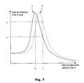
- FIG. 7is a graph showing how the variation of operational voltage with transmission frequency is effected by changes in resonant frequency of the system
- FIG. 8is a circuit diagram of an inductive power transfer system including an inductive feedback channel for providing coil-to-coil signal transfer concurrently with uninterrupted inductive power transfer between the coils in accordance with yet another embodiment of the invention.
- FIG. 9is a flowchart showing a method for inductively transferring a signal from the secondary inductive coil to a primary inductive coil of an inductive power transfer system according to still a further embodiment of the invention.
- FIG. 1showing a block diagram of the main elements of an inductive power transfer system 100 adapted to transmit power at a non-resonant frequency according to another embodiment of the invention.
- the inductive power transfer system 100consists of an inductive power outlet 200 configured to provide power to a remote secondary unit 300 .
- the inductive power outlet 200includes a primary inductive coil 220 wired to a power source 240 via a driver 230 .
- the driver 230is configured to provide an oscillating driving voltage to the primary inductive coil 220 .
- the secondary unit 300includes a secondary inductive coil 320 , wired to an electric load 340 , which is inductively coupled to the primary inductive coil 220 .
- the electric load 340draws power from the power source 240 .
- a communication channel 120may be provided between a transmitter 122 associated with the secondary unit 300 and a receiver 124 associated with the inductive power outlet 200 .
- the communication channel 120may provide feedback signals S and the like to the driver 230 .
- a voltage peak detector 140is provided to detect large increases in the transmission voltage. As will be descried below the peak detector 140 may be used to detect irregularities such as the removal of the secondary unit 200 , the introduction of power drains, short circuits or the like.
- FIG. 2is a graph showing how the amplitude of the operational voltage of an inductive power transfer system varies according to the transmission frequency. It is noted that the voltage is at its highest when the transmission frequency is equal to the resonant frequency f R of the system, this maximum amplitude is known as the resonance peak 2 . It is further noted that the slope of the graph is steepest in the regions 4 a , 4 b to either side of the resonance peak 2 . Thus in inductive transfer systems, which operate at or around resonance, a small variation in frequency results in a large change in induced voltage. Similarly, a small change in the resonant frequency of the system results in a large change in the induced voltage. For this reason prior art resonant inductive transfer systems are typically very sensitive to small fluctuations in environmental conditions or variations in alignment between the induction coils.
- the driver 230( FIG. 1 ) is configured and operable to transmit a driving voltage which oscillates at a transmission frequency which is substantially different from the resonant frequency of the inductive couple.
- the transmission frequencyis selected to lie within one of the near-linear regions 6 , 8 where the slope of the frequency-amplitude graph is less steep.
- FIG. 3A schematic diagram is shown representing a laptop computer 340 drawing power from an inductive power outlet 200 via a secondary power receiving unit 300 .
- the power receiving unit 300includes a secondary inductive coil 320 which is aligned to a primary inductive coil 220 in the inductive power outlet 200 . Any lateral displacement of the secondary power receiving unit 300 changes the alignment between the secondary inductive coil 320 to the primary inductive coil 220 . As a result of the changing alignment, the combined inductance of the coil pair changes which in turn changes the resonant frequency of the system.
- the inductive power outlet 200transmits power at the resonant frequency of the system, even a small lateral movement would reduce significantly the amplitude of the induced voltage.
- the inductive power outlet 200transmits power at a frequency in one of the regions 6 , 8 to either side of the resonance peak 2 ( FIG. 2 ) where the slope of the resonance graph is much shallower. Consequently, the system has a much larger tolerance of variations such as lateral movement.
- a further feature of embodiments of inductive power outlets transmitting at frequencies above the natural resonant frequency of the systemis that if the resonant frequency of the system increases for some reasons, then the transmission voltage increases sharply.
- a peak detector 140FIG. 1 is be provided to monitor the transmission voltage of the power outlet 200 and is configured to detect large increases in the transmission voltage indicating an increase in resonant frequency.
- any decrease in either the inductance L or the capacitance C of the systemincreases the resonant frequency and may be detected by the peak detector 140 .
- a peak detector 140As an example of the use of a peak detector 140 , reference is again made to FIG. 3 . It will be appreciated that in a desktop environment, conductive bodies such as a paper clip, metal rule, the metal casing a stapler, a hole-punch or any metallic objects may be introduced between the inductive power outlet 200 and the secondary power receiving unit 300 . The oscillating magnetic field produced by the primary coil 220 would then produce eddy currents in the conductive body heating it and thereby draining power from the primary coil 220 . Such a power drain may be wasteful and/or dangerous. Power drains such as described above generally reduce the inductance L of the system thereby increasing its resonant frequency.
- the inductance L of the systemmay also be reduced by the removal of the secondary coil 220 , the creation of a short circuit or the like.
- a peak detector 140wired to the inductive power outlet, may detect any of these scenarios as a large increase in transmission voltage.
- the power transfer systemmay be further configured to shut down, issue a warning or otherwise protect the user and the system in the event that the peak detector 140 detects such an increase in transmission voltage.
- FIG. 4is a circuit diagram of an inductive power outlet 6200 and secondary unit 6300 .
- the secondary unit 6300comprises a secondary coil 6320 wired to an electric load 6340 via a rectifier 6330 .
- the inductive power outlet 6200comprises a primary coil 6220 driven by a half-bridge converter 6230 connected to a power source 6240 .
- the half-bridge converter 6230is configured to drive the primary coil 6220 at a frequency higher than the resonant frequency of the system and a peak detector 6140 is configured to detect increases in the transmission voltage.
- FIG. 4Although only a half-bridge converter is represented in FIG. 4 , it is noted that other possible driving circuits include: a DC-to-DC converter, an AC-to-DC converter, an AC-to-AC converter, a flyback transformer, a full-bridge converter, a flyback converter or a forward converter for example.
- the transmission frequencymay be used to regulate power transfer.
- Prior art inductive power transfer systemstypically regulate power transfer by altering the duty cycle of the transmission voltage.
- the driver 230may be configured to regulate power transfer by adjusting the transmission frequency.
- the frequency of transmissionmay be selected to be in the approximately linear region 8 of the curve between a lower frequency value of f L , and an upper frequency value of f U .
- a transmission frequency f thigher than the resonant frequency f R of the system, produces an induced voltage of V t .
- the induced voltagecan be increased by reducing the transmission frequency so that it is closer to the resonant frequency f R .
- the induced voltagemay be reduced by increasing the transmission frequency so that it is further from the resonant frequency f R .
- an adjustment of transmission frequency by ⁇ fproduces a change in induced voltage of ⁇ V.
- a communication channel 120( FIG. 1 ) is provided between the secondary unit 300 and the inductive power outlet 200 to communicate the required operating parameters.
- operating parameters the communication channel 120may be used to indicate the transmission frequency required by the electric load 340 to the driver 230 .
- the communication channel 120may further provide a feedback signal during power transmission.
- the feedback transmissionmay communicate required or monitored operating parameters of the electric load 240 such as:
- a microcontroller in the driver 230may use such feedback parameters to calculate the required transmission frequency and to adjust the driver accordingly.
- simple feedback signalsmay be provided indicating whether more or less power is required.
- the operating parameters of the electric loadmay be monitored and their values may be transmitted to the power outlet via the communications channel 120 .
- a processor in the power outletmay then calculate the required transmission frequency directly.
- the method described hereaboverefers to a non-resonant transmission frequency lying within the linear region 8 ( FIG. 2 ), higher than the resonant peak 2 . It will be appreciated however that in alternative embodiments frequency-controlled power regulation may be achieved when the transmission frequency lies in the lower linear region of the resonance curve. Nevertheless, for certain embodiments, the selection of transmission frequencies in the higher linear 8 may be preferred, particularly where peak detection, as described above, is required.
- various transmitters 122 and receivers 124may be used for the communication channel 120 .
- the primary and secondary coils 220 , 320are galvanically isolated optocouplers, for example, may be used.
- a light emitting diodeserves as a transmitter and sends encoded optical signals over short distances to a photo-transistor which serves as a receiver.
- optocouplerstypically need to be aligned such that there is a line-of-sight between transmitter and receiver.
- the primary and secondary coils 220 , 320may themselves serve as the transmitter 122 and receiver 124 .
- an optical transmittersuch as a light emitting diode (LED) for example, is incorporated within the secondary unit 300 and is configured and operable to transmit electromagnetic radiation of a type and intensity capable of penetrating the casings of both the secondary unit 300 , and the power outlet 200 .
- An optical receiversuch as a photodiode, a phototransistor, a light dependent resistors of the like, is incorporated within the power outlet 200 for receiving the electromagnetic radiation.
- an inductive communications channel 2120is incorporated into the inductive power transfer system 2100 for transferring signals between a inductive power outlet 2200 and a remote secondary unit 2300 .
- the communication channel 2120is configured to produce an output signal S out in the power outlet 2200 when an input signal S in is provided by the secondary unit 2300 without interrupting the inductive power transfer from the outlet 2200 to the secondary unit 2300 .
- the inductive power outlet 2200includes a primary inductive coil 2220 wired to a power source 2240 via a driver 2230 .
- the driver 2230is configured to provide an oscillating driving voltage to the primary inductive coil 2220 , typically at a voltage transmission frequency f t which is higher than the resonant frequency f R of the system.
- the secondary unit 2300includes a secondary inductive coil 2320 , wired to an electric load 2340 , which is inductively coupled to the primary inductive coil 2220 .
- the electric load 2340draws power from the power source 2240 .
- a rectifier 2330may be provided to rectify the alternating current signal induced in the secondary coil 2320 .
- An inductive communication channel 2120is provided for transferring signals from the secondary inductive coil 2320 to the primary inductive coil 2220 concurrently with uninterrupted inductive power transfer from the primary inductive coil 2220 to the secondary inductive coil 2320 .
- the communication channel 2120may provide feedback signals to the driver 2230 .
- the inductive communication channel 2120includes a transmission circuit 2122 and a receiving circuit 2124 .
- the transmission circuit 2122is wired to the secondary coil 2320 , optionally via a rectifier 2330 , and the receiving circuit 2124 is wired to the primary coil 2220 .
- the signal transmission circuit 2122includes at least one electrical element 2126 , selected such that when it is connected to the secondary coil 2320 , the resonant frequency f R of the system increases.
- the transmission circuit 2122is configured to selectively connect the electrical element 2126 to the secondary coil 2320 .
- the electrical element 2126may be have a low resistance for example, with a resistance say under 50 ohms and preferably about 1 ohm.
- the signal receiving circuit 2124includes a voltage peak detector 2128 configured to detect large increases in the transmission voltage.
- a voltage peak detector 2128configured to detect large increases in the transmission voltage.
- the transmission circuit 2122may be used to send a signal pulse to the receiving circuit 2124 and a coded signal may be constructed from such pulses.
- the transmission circuit 2122may also include a modulator (not shown) for modulating a bit-rate signal with the input signal S in .
- the electrical element 2126may then be connected to the secondary inductive coil 2320 according to the modulated signal.
- the receiving circuit 2124may include a demodulator (not shown) for demodulating the modulated signal.
- the voltage peak detector 2128may be connected to a correlator for cross-correlating the amplitude of the primary voltage with the bit-rate signal thereby producing the output signal S out .
- a plurality of electrical elements 2126may be provided which may be selectively connected to induce a plurality of voltage peaks of varying sizes in the amplitude of the primary voltage.
- the size of the voltage peak detected by the peak detector 2128may be used to transfer multiple signals.
- FIG. 7is a graph showing how the amplitude of the operational voltage varies according to the transmission frequency. It is noted that the voltage is at its highest when the transmission frequency is equal to the resonant frequency f R of the system, this maximum amplitude is known as the resonance peak 2 . If the resonant frequency f R of the system increases, a new resonance peak 2 ′ is produced.
- an inductive power transfer system 2100operates at a given transmission frequency f t which is higher than the resonant frequency f R of the system.
- the normal operating voltage V tis monitored by the voltage peak detector 2128 .
- the electric element 2126is connected to the secondary inductive coil 2320 the resonant frequency of the system increases. Therefore, the operating voltage increases to a higher value V t ′. This increase is detected by the voltage peak detector 2128 .
- the present inventionenables data signals to be transferred from the secondary coil 2320 to the primary coil 2220 concurrently with inductive transfer of power from the primary coil 2220 to the secondary coil 2320 . Consequently, the signal transfer system may be used to provide feedback signals for real time power regulation.
- FIG. 8shows an exemplary circuit diagram of an inductive power outlet 7200 and a secondary unit 7300 , according to another embodiment of the invention.
- An inductive feedback channel 7120is provided for transferring signals between the coils concurrently with uninterrupted inductive power transfer.
- the inductive power outlet 7200comprises a primary coil 7220 driven by a half-bridge converter 7230 connected to a power source 7240 .
- the half-bridge converter 7230is configured to drive the primary coil 7220 at a frequency higher than the resonant frequency of the system.
- the secondary unit 7300comprises a secondary coil 7320 wired to the input terminals T 1 , T 2 of a rectifier 7330 , and an electric load 7340 wired to the output terminals T 3 , T 4 of the rectifier 7330 .
- the inductive feedback channel 7120comprises a transmission circuit 7122 , in the secondary unit 7300 and a receiving circuit 7124 in the inductive power outlet 7200 .
- the transmission circuit 7122comprises an electrical resistor 7126 connected to the rectifier 7330 via a power MOSFET switch 7125 .
- a modulator 7123may provide an input signal S in to the power MOSFET 7125 .
- the transmission circuit 7122is wired to one input terminal T 1 and one output terminal T 3 of the rectifier 7330 .
- This configurationis particularly advantageous as, even when the transmission circuit 7122 is connected, the resistor 7126 only draws power from the system during one half of the AC cycle, thereby significantly reducing power loss.
- the receiving circuit 7124includes a voltage peak detector 7128 that is configured to detect increases in the transmission voltage, and a demodulator 7129 for producing an output signal S out .
- FIG. 9a flowchart is presented showing the main steps in a method for transferring a signal from the secondary inductive coil to a primary inductive coil of an inductive power transfer system.
- the methodincludes the following steps:
- the inductive communication channel 2120may be used to transfer a feedback signal from the secondary inductive coil to the primary inductive coil for regulating power transfer across an inductive power coupling as described above.
- Inductive power receiversmay be used to wirelessly provide power for a variety of electrical devices.
- Embodiments of the present inventionmay be integrated into such inductive power receivers.
- heat loss from the non-resonant systemis lower.
- embodiments of the current inventionmay be of particular use when incorporated within high power applications such as power tools, kitchen appliances, bathroom appliances, computers, media players, office equipment and the like.
- the reduced heat loss, associated with embodiments of the non-resonant systems of the invention,is particularly useful when heat dissipation is difficult for example when power receiver has small dimensions or for heat-sensitive equipment such as measuring devices. Also, it is desirable that devices implanted into a living body do not dissipate large amounts of heat into the body. Therefore, non-resonant inductive transfer is well suited to implanted devices, such as pace makers, trackers and the like.
- embodiments of the present inventionmay be advantageously utilized in inductive power transfer systems in any of the various applications in which power is transferred from a primary coil to a remote secondary coil.
- applicationsinclude:
- the inductive transfer systemhas a higher tolerance to environmental fluctuations and variations in inductive coil alignment than other transfer systems and the frequency may be used to regulate power transfer.
- a peak detectormay be used to indicate hazards and provide an inductive communication channel.
Landscapes
- Engineering & Computer Science (AREA)
- Computer Networks & Wireless Communication (AREA)
- Power Engineering (AREA)
- Near-Field Transmission Systems (AREA)
Abstract
Description
it is noted that any decrease in either the inductance L or the capacitance C of the system increases the resonant frequency and may be detected by the
- required operating voltage, current, temperature or power for the
electric load 240, - the measured voltage, current, temperature or power supplied to the
electric load 240 during operation, - the measured voltage, current, temperature or power received by the
electric load 240 during operation and the like.
- required operating voltage, current, temperature or power for the
- Step (a)—The
driver 230 provides an oscillating voltage at a transmission frequency ftwhich is higher than the resonant frequency fRof the system. - Step (b)—A secondary voltage is induced in the
secondary coil 320. - Step (c)—A power monitor in the
secondary unit 300, monitors the power received by theelectric load 340. - Step (d)—If the power received by the
electric load 340 lies within a predetermined range then no action is taken. If the power received by theelectric load 340 is below the predetermined range, then a feedback signal of a first type Sais sent to the driver. If the power received by theelectric load 340 is above the predetermined range, then a feedback signal of a second type Sbis sent to the driver. - Step (e)—A feedback signal is received by the
driver 230. - Step (f)—If the received feedback signal is of the first type Sa, then the transmission frequency is increased by an incremental value +δf1. If the received feedback signal is of the second type Sb, then the transmission frequency is decreased by an incremental value −δf2.
- Step (i)—connecting the primary inductive coil to a voltage monitor for monitoring the amplitude of a primary voltage across the primary coil;
- Step (ii)—connecting the secondary inductive coil to a transmission circuit for selectively increasing the resonant frequency of the inductive power transfer system;
- Step (iii)—providing an oscillating voltage to the primary inductive coil at an initial transmission frequency higher than the resonant frequency thereby inducing a voltage in the secondary inductive coil;
- Step (iv)—using the transmission circuit to modulate a bit-rate signal with the input signal to create a modulated signal and connecting the electrical element to the secondary inductive coil intermittently according to the modulated signal, and
- Step (v)—using the voltage monitor to cross-correlate the amplitude of the primary voltage with the bit-rate signal for producing an output signal.
- inductive chargers for use charging electronic devices,
- inductive power adaptors for powering electronic devices such as computers, televisions, kitchen appliances, office equipment and the like,
- medical applications in which power is transferred remotely to devices implanted in a patient,
- communications with remote RFID tags,
- military application in which power is transferred across thick armored plating,
- communication or inductive energy transfer to secondary inductive coils buried underground.
- communication or inductive energy transfer to secondary inductive coils submerged under water, for example in submarine applications, and
- communication or inductive energy with secondary coils which are moving relative to the primary coil.
Claims (19)
Priority Applications (10)
| Application Number | Priority Date | Filing Date | Title |
|---|---|---|---|
| US12/497,088US8188619B2 (en) | 2008-07-02 | 2009-07-02 | Non resonant inductive power transmission system and method |
| US13/205,672US8981598B2 (en) | 2008-07-02 | 2011-08-09 | Energy efficient inductive power transmission system and method |
| US13/458,164US8427012B2 (en) | 2008-07-02 | 2012-04-27 | Non resonant inductive power transmission system and method |
| US14/283,981US9006937B2 (en) | 2008-07-02 | 2014-05-21 | System and method for enabling ongoing inductive power transmission |
| US14/306,123US9099894B2 (en) | 2008-07-02 | 2014-06-16 | System and method for coded communication signals regulating inductive power transmission |
| US14/740,108US20150311956A1 (en) | 2008-07-02 | 2015-06-15 | System and method for coded communication signals regulating inductive power transmission |
| US16/053,126US10680469B2 (en) | 2008-07-02 | 2018-08-02 | System and method for coded communication signals regulating inductive power transmissions |
| US16/894,041US11387688B2 (en) | 2008-07-02 | 2020-06-05 | System and method for coded communication signals regulating inductive power transmissions |
| US17/861,828US11979201B2 (en) | 2008-07-02 | 2022-07-11 | System and method for coded communication signals regulating inductive power transmissions |
| US18/627,920US20240340041A1 (en) | 2008-07-02 | 2024-04-05 | System and method for coded communication signals regulating inductive power transmissions |
Applications Claiming Priority (3)
| Application Number | Priority Date | Filing Date | Title |
|---|---|---|---|
| US12952608P | 2008-07-02 | 2008-07-02 | |
| US12985908P | 2008-07-24 | 2008-07-24 | |
| US12/497,088US8188619B2 (en) | 2008-07-02 | 2009-07-02 | Non resonant inductive power transmission system and method |
Related Child Applications (2)
| Application Number | Title | Priority Date | Filing Date |
|---|---|---|---|
| US13/205,672Continuation-In-PartUS8981598B2 (en) | 2008-07-02 | 2011-08-09 | Energy efficient inductive power transmission system and method |
| US13/458,164ContinuationUS8427012B2 (en) | 2008-07-02 | 2012-04-27 | Non resonant inductive power transmission system and method |
Publications (2)
| Publication Number | Publication Date |
|---|---|
| US20100066176A1 US20100066176A1 (en) | 2010-03-18 |
| US8188619B2true US8188619B2 (en) | 2012-05-29 |
Family
ID=42006567
Family Applications (2)
| Application Number | Title | Priority Date | Filing Date |
|---|---|---|---|
| US12/497,088Active2030-11-16US8188619B2 (en) | 2008-07-02 | 2009-07-02 | Non resonant inductive power transmission system and method |
| US13/458,164ActiveUS8427012B2 (en) | 2008-07-02 | 2012-04-27 | Non resonant inductive power transmission system and method |
Family Applications After (1)
| Application Number | Title | Priority Date | Filing Date |
|---|---|---|---|
| US13/458,164ActiveUS8427012B2 (en) | 2008-07-02 | 2012-04-27 | Non resonant inductive power transmission system and method |
Country Status (1)
| Country | Link |
|---|---|
| US (2) | US8188619B2 (en) |
Cited By (26)
| Publication number | Priority date | Publication date | Assignee | Title |
|---|---|---|---|---|
| US20110264945A1 (en)* | 2010-04-26 | 2011-10-27 | Fu Da Tong Technology Co., Ltd. | Power supplying and data transmitting method for induction type power supply system |
| US20110278942A1 (en)* | 2010-05-11 | 2011-11-17 | Searete Llc, A Limited Liability Corporation Of The State Of Delaware | Wearable power source carryable by a health care provider |
| US20110282415A1 (en)* | 2010-05-11 | 2011-11-17 | Searete Llc, A Limited Liability Corporation Of The State Of Delaware | Wearable wireless power transmitter |
| US20110278957A1 (en)* | 2010-05-11 | 2011-11-17 | Searete Llc, A Limited Liability Corporation Of The State Of Delaware | Wearable power source |
| US20120007443A1 (en)* | 2011-02-01 | 2012-01-12 | Tsai Ming-Chiu | Method for power self-regulation in a high-power induction type power source |
| US8427014B2 (en) | 2010-05-11 | 2013-04-23 | The Invention Science Fund I, Llc | System including wearable power receiver and wearable power-output device |
| US20130119777A1 (en)* | 2011-11-03 | 2013-05-16 | Shaw Industries Group | Wireless energy transfer systems |
| US20140125146A1 (en)* | 2008-03-17 | 2014-05-08 | Powermat Technologies, Ltd. | Transmission-guard system and method for an inductive power supply |
| US8941267B2 (en) | 2011-06-07 | 2015-01-27 | Fu Da Tong Technology Co., Ltd. | High-power induction-type power supply system and its bi-phase decoding method |
| US8981600B2 (en)* | 2011-02-01 | 2015-03-17 | Fu Da Tong Technology Co., Ltd. | Low-loss data transmission method for high-power induction-type power supply system |
| US9048881B2 (en) | 2011-06-07 | 2015-06-02 | Fu Da Tong Technology Co., Ltd. | Method of time-synchronized data transmission in induction type power supply system |
| US9075587B2 (en) | 2012-07-03 | 2015-07-07 | Fu Da Tong Technology Co., Ltd. | Induction type power supply system with synchronous rectification control for data transmission |
| US20160020640A1 (en)* | 2014-07-21 | 2016-01-21 | Jessica Kristin Rogers | Portable Method for Charging Mobile Devices |
| US9413197B2 (en) | 2010-05-31 | 2016-08-09 | Fu Da Tong Technology Co., Ltd. | Inductive power supply system and intruding metal detection method thereof |
| US9509168B2 (en) | 2013-09-04 | 2016-11-29 | Freescale Semiconductor, Inc. | Wireless power transmitters with wide input voltage range and methods of their operation |
| US9600021B2 (en) | 2011-02-01 | 2017-03-21 | Fu Da Tong Technology Co., Ltd. | Operating clock synchronization adjusting method for induction type power supply system |
| US9628147B2 (en) | 2011-02-01 | 2017-04-18 | Fu Da Tong Technology Co., Ltd. | Method of automatically adjusting determination voltage and voltage adjusting device thereof |
| US9671444B2 (en) | 2011-02-01 | 2017-06-06 | Fu Da Tong Technology Co., Ltd. | Current signal sensing method for supplying-end module of induction type power supply system |
| US9793739B2 (en) | 2013-08-07 | 2017-10-17 | Sandisk Technologies Llc | Wireless power transmitting device |
| US9831687B2 (en) | 2011-02-01 | 2017-11-28 | Fu Da Tong Technology Co., Ltd. | Supplying-end module for induction-type power supply system and signal analysis circuit therein |
| US10038338B2 (en) | 2011-02-01 | 2018-07-31 | Fu Da Tong Technology Co., Ltd. | Signal modulation method and signal rectification and modulation device |
| US10056944B2 (en) | 2011-02-01 | 2018-08-21 | Fu Da Tong Technology Co., Ltd. | Data determination method for supplying-end module of induction type power supply system and related supplying-end module |
| US11114895B2 (en) | 2007-01-29 | 2021-09-07 | Powermat Technologies, Ltd. | Pinless power coupling |
| US11387688B2 (en) | 2008-07-02 | 2022-07-12 | Powermat Technologies, Ltd. | System and method for coded communication signals regulating inductive power transmissions |
| US11979201B2 (en) | 2008-07-02 | 2024-05-07 | Powermat Technologies Ltd. | System and method for coded communication signals regulating inductive power transmissions |
| US12376787B2 (en) | 2020-07-21 | 2025-08-05 | DePuy Synthes Products, Inc. | Bone fixation monitoring system |
Families Citing this family (40)
| Publication number | Priority date | Publication date | Assignee | Title |
|---|---|---|---|---|
| US8169185B2 (en) | 2006-01-31 | 2012-05-01 | Mojo Mobility, Inc. | System and method for inductive charging of portable devices |
| US7952322B2 (en)* | 2006-01-31 | 2011-05-31 | Mojo Mobility, Inc. | Inductive power source and charging system |
| US11201500B2 (en) | 2006-01-31 | 2021-12-14 | Mojo Mobility, Inc. | Efficiencies and flexibilities in inductive (wireless) charging |
| US11329511B2 (en) | 2006-06-01 | 2022-05-10 | Mojo Mobility Inc. | Power source, charging system, and inductive receiver for mobile devices |
| US7948208B2 (en) | 2006-06-01 | 2011-05-24 | Mojo Mobility, Inc. | Power source, charging system, and inductive receiver for mobile devices |
| EP2083407B1 (en)* | 2008-01-25 | 2012-05-16 | Pepperl + Fuchs GmbH | Device and method for contact-free energy and data transfer |
| US9960640B2 (en)* | 2008-03-17 | 2018-05-01 | Powermat Technologies Ltd. | System and method for regulating inductive power transmission |
| WO2013080212A2 (en)* | 2011-12-02 | 2013-06-06 | Powermat Technologies Ltd. | System and method for regulating inductive power transmission |
| US9960642B2 (en) | 2008-03-17 | 2018-05-01 | Powermat Technologies Ltd. | Embedded interface for wireless power transfer to electrical devices |
| US20110050164A1 (en) | 2008-05-07 | 2011-03-03 | Afshin Partovi | System and methods for inductive charging, and improvements and uses thereof |
| US11476566B2 (en) | 2009-03-09 | 2022-10-18 | Nucurrent, Inc. | Multi-layer-multi-turn structure for high efficiency wireless communication |
| JP5526833B2 (en)* | 2010-02-05 | 2014-06-18 | ソニー株式会社 | Wireless power transmission device |
| WO2011156768A2 (en) | 2010-06-11 | 2011-12-15 | Mojo Mobility, Inc. | System for wireless power transfer that supports interoperability, and multi-pole magnets for use therewith |
| NZ586175A (en)* | 2010-06-15 | 2013-11-29 | Powerbyproxi Ltd | An icpt system, components and design method |
| US9444517B2 (en)* | 2010-12-01 | 2016-09-13 | Triune Systems, LLC | Coupled inductor power transfer system |
| DE102010055696A1 (en)* | 2010-12-22 | 2012-06-28 | Airbus Operations Gmbh | A system for contactless energy transfer, use of a system for contactless energy transfer and vehicle with a system for contactless energy transfer between a first vehicle part and a second vehicle part |
| WO2012093398A2 (en) | 2011-01-05 | 2012-07-12 | Powermat Technologies Ltd. | System and method for integrating inductive power functionality into furniture |
| US9178369B2 (en) | 2011-01-18 | 2015-11-03 | Mojo Mobility, Inc. | Systems and methods for providing positioning freedom, and support of different voltages, protocols, and power levels in a wireless power system |
| US9496732B2 (en) | 2011-01-18 | 2016-11-15 | Mojo Mobility, Inc. | Systems and methods for wireless power transfer |
| US10115520B2 (en) | 2011-01-18 | 2018-10-30 | Mojo Mobility, Inc. | Systems and method for wireless power transfer |
| US11342777B2 (en) | 2011-01-18 | 2022-05-24 | Mojo Mobility, Inc. | Powering and/or charging with more than one protocol |
| JP5756925B2 (en)* | 2011-05-19 | 2015-07-29 | パナソニックIpマネジメント株式会社 | Power receiving device provided in electrical equipment |
| JP5899490B2 (en)* | 2011-07-20 | 2016-04-06 | パナソニックIpマネジメント株式会社 | Contactless power supply system |
| EP3410642B1 (en)* | 2011-12-28 | 2021-05-19 | Lutron Technology Company LLC | Load control system having a broadcast controller with a diverse wireless communication system |
| US9531441B2 (en) | 2012-02-21 | 2016-12-27 | Lg Innotek Co., Ltd. | Wireless power receiver and method of managing power thereof |
| US20130271069A1 (en) | 2012-03-21 | 2013-10-17 | Mojo Mobility, Inc. | Systems and methods for wireless power transfer |
| US9722447B2 (en) | 2012-03-21 | 2017-08-01 | Mojo Mobility, Inc. | System and method for charging or powering devices, such as robots, electric vehicles, or other mobile devices or equipment |
| WO2014006627A1 (en)* | 2012-07-05 | 2014-01-09 | Powermat Technologies Ltd. | System and method for providing inductive power at multiple power levels |
| GB2511478B (en) | 2012-12-14 | 2015-04-15 | Alexsava Holdings Ltd | Inductive power transfer system |
| JP6135471B2 (en)* | 2012-12-19 | 2017-05-31 | Tdk株式会社 | Power transmission device and wireless power transmission system using the same |
| US9837846B2 (en) | 2013-04-12 | 2017-12-05 | Mojo Mobility, Inc. | System and method for powering or charging receivers or devices having small surface areas or volumes |
| US9197291B2 (en)* | 2013-06-17 | 2015-11-24 | Infineon Technologies Ag | Circuit arrangement and method for bidirectional data transmission |
| JP6360649B2 (en) | 2013-08-06 | 2018-07-18 | モーメンタム ダイナミックス コーポレーション | Method and apparatus for detecting coil alignment error in wireless inductive power transmission |
| CN105226843B (en)* | 2014-05-27 | 2017-09-15 | 松下知识产权经营株式会社 | Wireless power transmission system and power transmission device of wireless power transmission system |
| EP3107176B1 (en)* | 2015-06-18 | 2018-04-04 | STMicroelectronics (Grand Ouest) SAS | Method for managing a wireless power transfer from an emitter to a receiver, and corresponding emitter |
| WO2017062552A1 (en)* | 2015-10-07 | 2017-04-13 | Tc1 Llc | Resonant power transfer systems having efficiency optimization based on receiver impedance |
| EP3168953A1 (en)* | 2015-11-13 | 2017-05-17 | TE Connectivity Germany GmbH | Contactless connector system having feedback from secondary side |
| US11444485B2 (en) | 2019-02-05 | 2022-09-13 | Mojo Mobility, Inc. | Inductive charging system with charging electronics physically separated from charging coil |
| WO2021050847A1 (en)* | 2019-09-13 | 2021-03-18 | Texas Institute Of Science, Inc. | Contactless charging apparatus and method for contactless charging |
| US11223222B2 (en) | 2019-09-13 | 2022-01-11 | Texas Institute Of Science, Inc. | Contactless charging apparatus and method for contactless charging |
Citations (155)
| Publication number | Priority date | Publication date | Assignee | Title |
|---|---|---|---|---|
| US723836A (en) | 1902-10-24 | 1903-03-31 | Percy Foote Cowing | Induction apparatus. |
| US2415688A (en) | 1943-05-05 | 1947-02-11 | Mrs Helen J Hall Jr | Induction device |
| GB778072A (en) | 1954-04-09 | 1957-07-03 | Frank Walter Holland | Improvements in electrical table lamps |
| US3771085A (en) | 1971-08-10 | 1973-11-06 | Tokyo Keiki Kk | Deviation detecting apparatus |
| US3938018A (en) | 1974-09-16 | 1976-02-10 | Dahl Ernest A | Induction charging system |
| US4160193A (en) | 1977-11-17 | 1979-07-03 | Richmond Abraham W | Metal vapor electric discharge lamp system |
| US4431948A (en) | 1982-08-09 | 1984-02-14 | Standun Controls, Inc. | Apparatus for control of load power consumption |
| EP0160990A2 (en) | 1984-05-11 | 1985-11-13 | Telefunken Systemtechnik Gmbh | Inductive transmission of power and data |
| US4754180A (en) | 1985-04-01 | 1988-06-28 | Honeywell Inc. | Forceless non-contacting power transformer |
| EP0357839A1 (en) | 1988-09-05 | 1990-03-14 | Cockerill-Sambre S.A. | Process for electroplating tin |
| US4977515A (en) | 1988-08-29 | 1990-12-11 | Rudden Frank G | Load management device and method of use |
| US5221877A (en) | 1992-03-10 | 1993-06-22 | Davis Controls Corporation | Power reduction control for inductive lighting installation |
| EP0558316A1 (en) | 1992-02-27 | 1993-09-01 | G2 Design Limited | An inductive loop power transmission system |
| US5278771A (en) | 1991-07-12 | 1994-01-11 | Seti Corporation | Programmable timed electrical power management device |
| FR2695285A3 (en) | 1992-09-02 | 1994-03-04 | Cableco Sa | Lighting appts. with mains fed lights - has two dielectric containers and high-frequency generator with lighting connected to terminals with induced electromagnetic field |
| US5367242A (en) | 1991-09-20 | 1994-11-22 | Ericsson Radio Systems B.V. | System for charging a rechargeable battery of a portable unit in a rack |
| US5455466A (en) | 1993-07-29 | 1995-10-03 | Dell Usa, L.P. | Inductive coupling system for power and data transfer |
| US5486394A (en) | 1994-08-26 | 1996-01-23 | E-Z Taping System, Inc. | Self-release self-adhesive drywall tape |
| WO1996002879A1 (en) | 1994-07-19 | 1996-02-01 | Elonex Technologies, Inc. | Micro personal digital assistant |
| US5528113A (en) | 1993-10-21 | 1996-06-18 | Boys; John T. | Inductive power pick-up coils |
| US5550452A (en) | 1993-07-26 | 1996-08-27 | Nintendo Co., Ltd. | Induction charging apparatus |
| US5600225A (en) | 1994-06-30 | 1997-02-04 | Nippon Electric Co | Noncontacting charging device |
| FR2739929A1 (en) | 1995-10-11 | 1997-04-18 | Marwal Systems | Motor car fuel tank with magnetically coupled fuel level sensor |
| US5680035A (en) | 1995-03-07 | 1997-10-21 | Haim; Neerman | Electronic filter |
| US5713939A (en) | 1996-09-16 | 1998-02-03 | Sulzer Intermedics Inc. | Data communication system for control of transcutaneous energy transmission to an implantable medical device |
| US5734254A (en) | 1996-12-06 | 1998-03-31 | Hewlett-Packard Company | Battery pack and charging system for a portable electronic device |
| EP0845695A2 (en) | 1996-11-30 | 1998-06-03 | Lüder, Ernst, Prof. Dr.-Ing. habil. | Method of manufacturing of liquid crystal displays on plastic films using bistable liquid crystals |
| US5762250A (en) | 1994-07-06 | 1998-06-09 | Truckin' Movers Corporation | Convertible carrying case and work platform for small electronic devices |
| US5821728A (en) | 1996-07-22 | 1998-10-13 | Schwind; John P. | Armature induction charging of moving electric vehicle batteries |
| US5821731A (en) | 1996-01-30 | 1998-10-13 | Sumitomo Wiring Systems, Ltd. | Connection system and connection method for an electric automotive vehicle |
| US5907285A (en) | 1993-12-09 | 1999-05-25 | Steelcase Inc. | Furniture unit having a modular communication network |
| US5929598A (en) | 1996-07-03 | 1999-07-27 | Uniden Corporation | Noncontact charging device, charger, cordless electric equipment, and noncontact charger |
| US5949214A (en) | 1997-11-04 | 1999-09-07 | Input/Output, Inc. | Rechargeable battery pack |
| US6042005A (en) | 1997-06-20 | 2000-03-28 | Basile; Mark R. | Personal identification and promotional system using personal and medical information |
| US6127799A (en) | 1999-05-14 | 2000-10-03 | Gte Internetworking Incorporated | Method and apparatus for wireless powering and recharging |
| US6211649B1 (en) | 1999-03-25 | 2001-04-03 | Sourcenext Corporation | USB cable and method for charging battery of external apparatus by using USB cable |
| US6230029B1 (en) | 1998-01-07 | 2001-05-08 | Advanced Mobile Solutions, Inc. | Modular wireless headset system |
| WO2002001557A1 (en) | 2000-06-27 | 2002-01-03 | Citizen Watch Co., Ltd. | Disk drive |
| WO2002015320A1 (en) | 2000-08-16 | 2002-02-21 | Inca Systems Co., Ltd. | Battery charging system and battery charging apparatus thereof |
| US20020057584A1 (en) | 2000-11-14 | 2002-05-16 | Salcomp Oy | Power supply arrangement and inductively coupled battery charger with wirelessly coupled control, and method for wirelessly controlling a power supply arrangement and an inductively coupled battery charger |
| US6396935B1 (en) | 1996-01-26 | 2002-05-28 | Veijo Sakari Makkonen | Headset and method for a headset |
| US6436299B1 (en) | 1999-06-21 | 2002-08-20 | Amway Corporation | Water treatment system with an inductively coupled ballast |
| US6441589B1 (en) | 2001-04-02 | 2002-08-27 | Bellsouth Intellectual Property Corporation | Portable battery recharge station |
| US20020154518A1 (en)* | 2001-04-20 | 2002-10-24 | Reinhold Elferich | System for wireless transmission of electrical power, a garment, a system of garments and method for the transmission of signals and/or electrical energy |
| US20020158512A1 (en) | 2001-04-26 | 2002-10-31 | Satoshi Mizutani | Mounting structure including communication system for transmitting multiplex control signal to vehicle electrical devices |
| US6484260B1 (en) | 1998-04-24 | 2002-11-19 | Identix, Inc. | Personal identification system |
| US6532298B1 (en) | 1998-11-25 | 2003-03-11 | Iridian Technologies, Inc. | Portable authentication device and method using iris patterns |
| US6586909B1 (en) | 2001-12-21 | 2003-07-01 | Ron Trepka | Parallel battery charging device |
| US6644557B1 (en) | 2002-03-25 | 2003-11-11 | Robert A Jacobs | Access controlled thermostat system |
| US20030210106A1 (en) | 2002-05-13 | 2003-11-13 | Splashpower Limited, A Company Incorporated In The Uk | Contact-less power transfer |
| US6673250B2 (en) | 1999-06-21 | 2004-01-06 | Access Business Group International Llc | Radio frequency identification system for a fluid treatment system |
| US20040023633A1 (en) | 2002-07-31 | 2004-02-05 | Gordon Mark A. | Handheld wireless device holder |
| US6721540B1 (en) | 1999-03-19 | 2004-04-13 | Seiko Epson Corporation | Electronic device |
| US6731071B2 (en) | 1999-06-21 | 2004-05-04 | Access Business Group International Llc | Inductively powered lamp assembly |
| US6766040B1 (en) | 2000-10-02 | 2004-07-20 | Biometric Solutions, Llc | System and method for capturing, enrolling and verifying a fingerprint |
| GB2399466A (en) | 2003-03-10 | 2004-09-15 | Univ City Hong Kong | Battery charging system |
| US20040195767A1 (en) | 2002-12-10 | 2004-10-07 | Mitch Randall | Systems and methods for providing electric power to mobile and arbitrarily positioned devices |
| US6803744B1 (en) | 1999-11-01 | 2004-10-12 | Anthony Sabo | Alignment independent and self aligning inductive power transfer system |
| US20040203537A1 (en) | 2003-04-14 | 2004-10-14 | Shikio Yoshida | Wireless transmission module |
| US6825620B2 (en) | 1999-06-21 | 2004-11-30 | Access Business Group International Llc | Inductively coupled ballast circuit |
| US20040242264A1 (en) | 2003-01-09 | 2004-12-02 | Samsung Electronics Co., Ltd. | Communication device and wireless headset apparatus |
| US20040261802A1 (en) | 2003-06-30 | 2004-12-30 | Griffin William T. | Stand for electrically heated cigarette smoking device |
| US20050007067A1 (en) | 1999-06-21 | 2005-01-13 | Baarman David W. | Vehicle interface |
| US20050083020A1 (en) | 2003-10-20 | 2005-04-21 | Baarman David W. | Electrostatic charge storage assembly |
| US6888438B2 (en) | 2001-06-15 | 2005-05-03 | City University Of Hong Kong | Planar printed circuit-board transformers with effective electromagnetic interference (EMI) shielding |
| WO2005043775A1 (en) | 2003-10-31 | 2005-05-12 | Auckland Uniservices Limited | Communication apparatus and method |
| US6894457B2 (en) | 2002-11-01 | 2005-05-17 | American Power Conversion Corporation | Universal multiple device power adapter and carry case |
| US20050130593A1 (en) | 2003-12-16 | 2005-06-16 | Michalak Gerald P. | Integrated wireless headset |
| US20050164636A1 (en) | 1995-05-18 | 2005-07-28 | Aura Communications Technology, Inc. | Inductive communication system and method |
| US20050169506A1 (en) | 2004-01-07 | 2005-08-04 | Identification International, Inc. | Low power fingerprint capture system, apparatus, and method |
| US20050192062A1 (en) | 2002-09-18 | 2005-09-01 | Mickle Marlin H. | Recharging method and apparatus |
| US20050233768A1 (en) | 2004-04-16 | 2005-10-20 | Hon Hai Precision Industry Co., Ltd. | Wireless transmitter and earphone based on 802.11a/b/g standard |
| JP2005327845A (en) | 2004-05-13 | 2005-11-24 | Matsushita Electric Ind Co Ltd | LED lighting device and display device |
| WO2006015143A2 (en) | 2004-07-28 | 2006-02-09 | Newton Peripherals, Llc | Peripheral devices for portable computer |
| US20060028176A1 (en) | 2004-07-22 | 2006-02-09 | Qingfeng Tang | Cellular telephone battery recharging apparatus |
| US20060043927A1 (en) | 2002-09-27 | 2006-03-02 | Splashpower Limited | Retention of rechargeable devices |
| US20060052144A1 (en) | 2004-09-08 | 2006-03-09 | Seil Oliver D | Holder, electrical supply, and RF transmitter unit for electronic devices |
| US20060061325A1 (en) | 2004-09-21 | 2006-03-23 | Qingfeng Tang | Apparatus for inductively recharging batteries |
| US7019620B2 (en) | 2001-07-04 | 2006-03-28 | Wampfler Aktiengesellschaft | Device for the inductive transmission of electrical power |
| US20060071632A1 (en) | 2004-09-24 | 2006-04-06 | Riad Ghabra | Efficient inductive battery recharging system |
| USD519275S1 (en) | 2005-03-09 | 2006-04-25 | Tbac Investment Trust | Carrier for digital player and headphones |
| US20060093132A1 (en) | 2004-08-30 | 2006-05-04 | Innovi Technologies Limited | Wireless earpiece for cell phone |
| US20060091222A1 (en) | 2004-10-25 | 2006-05-04 | Empower Technologies Inc. | Direct-mounted pouch for portable electronic device |
| US7043060B2 (en) | 2001-07-17 | 2006-05-09 | Niccole Family Trust | Fingerprint-actuated padlock |
| US20060202665A1 (en) | 2005-03-10 | 2006-09-14 | Microsoft Corporation | Inductive powering surface for powering portable devices |
| US7126450B2 (en) | 1999-06-21 | 2006-10-24 | Access Business Group International Llc | Inductively powered apparatus |
| US7164255B2 (en) | 2002-06-10 | 2007-01-16 | City University Of Hong Kong | Inductive battery charger system with primary transformer windings formed in a multi-layer structure |
| US20070023559A1 (en) | 2005-07-26 | 2007-02-01 | James Scapillato | Electronic device case |
| US7180265B2 (en) | 2001-06-29 | 2007-02-20 | Nokia Corporation | Charging device with an induction coil |
| GB2429372A (en) | 2005-08-16 | 2007-02-21 | Zarlink Semiconductor Ab | A coil functioning as an inductive power conversion element and as an antenna |
| US20070057763A1 (en) | 2005-09-12 | 2007-03-15 | Imation Corp. | Wireless handheld device with local biometric authentication |
| US20070076459A1 (en) | 2003-05-02 | 2007-04-05 | Limpkin George A | Apparatus for supplying energy to a load and a related system |
| US7212414B2 (en) | 1999-06-21 | 2007-05-01 | Access Business Group International, Llc | Adaptive inductive power supply |
| US7210940B2 (en) | 2002-11-19 | 2007-05-01 | Huntleigh Technology Plc | Connector with inductive coupling |
| US7224086B2 (en) | 2002-11-01 | 2007-05-29 | American Power Conversion Corporation | Universal multiple device power adapter and carry case |
| US20070136593A1 (en) | 2005-12-14 | 2007-06-14 | Richard Plavcan | Secure information storage apparatus |
| US20070165371A1 (en) | 2006-01-13 | 2007-07-19 | Marware, Inc. | Portable digital media player case |
| US20070182367A1 (en) | 2006-01-31 | 2007-08-09 | Afshin Partovi | Inductive power source and charging system |
| US20070202931A1 (en) | 2006-02-27 | 2007-08-30 | Universal Power Holding Ltd. | Data communications enabled by wire free power transfer |
| USD553852S1 (en) | 2006-01-13 | 2007-10-30 | Marware, Inc. | Portable digital media player case |
| US20070279002A1 (en) | 2006-06-01 | 2007-12-06 | Afshin Partovi | Power source, charging system, and inductive receiver for mobile devices |
| US20080030985A1 (en) | 2006-08-07 | 2008-02-07 | Eun-Chae Jeon | Backlight assembly and display apparatus having the same |
| US20080049988A1 (en) | 2004-04-06 | 2008-02-28 | Biometrx Technologies, Inc | Method of, and System for, Accessing a Home or Dwelling |
| US20080055047A1 (en) | 2006-08-31 | 2008-03-06 | Semiconductor Energy Laboratory Co., Ltd. | Semiconductor device |
| WO2008030985A2 (en) | 2006-09-06 | 2008-03-13 | Newton Peripherals Llc | Wireless headset |
| US20080079388A1 (en) | 2006-10-03 | 2008-04-03 | Visteon Global Technologies, Inc. | Wireless charging device |
| US7385357B2 (en) | 1999-06-21 | 2008-06-10 | Access Business Group International Llc | Inductively coupled ballast circuit |
| US7392068B2 (en) | 2002-03-01 | 2008-06-24 | Mobilewise | Alternative wirefree mobile device power supply method and system with free positioning |
| US20080157715A1 (en) | 2006-01-07 | 2008-07-03 | Egate-International Gmbh | Plug-type charger for small electrical device |
| WO2008086080A2 (en) | 2007-01-03 | 2008-07-17 | Newton Peripherals, Llc | Dongle device |
| WO2008093334A2 (en) | 2007-01-29 | 2008-08-07 | Powermat Ltd | Pinless power coupling |
| US20080223926A1 (en) | 2007-03-01 | 2008-09-18 | Miller Brian S | Biometric control of equipment |
| WO2008114268A2 (en) | 2007-03-22 | 2008-09-25 | Powermat Ltd | Signal transfer system |
| US20080265835A1 (en) | 2007-04-26 | 2008-10-30 | Visteon Global Technologies, Inc. | Wireless power transfer system |
| EP1990734A1 (en) | 2007-05-09 | 2008-11-12 | Menstecnica S.R.L. | Portable and independent system for storage and display of passwords and pins |
| US7462951B1 (en) | 2004-08-11 | 2008-12-09 | Access Business Group International Llc | Portable inductive power station |
| US20090026959A1 (en) | 2007-07-27 | 2009-01-29 | Jung Tsung Lin | Non-contact light emitting display for vehicle |
| US20090040807A1 (en) | 2007-08-06 | 2009-02-12 | Kabushiki Kaisha Toshiba | Semiconductor memory device |
| USD586809S1 (en) | 2007-08-02 | 2009-02-17 | Newton Peripherals, Llc | Dongle |
| US20090047768A1 (en) | 2007-08-15 | 2009-02-19 | Texas Instruments Incorporated | Formation of shallow junctions by diffusion from a dielectric doped by cluster or molecular ion beams |
| US20090047769A1 (en) | 2007-08-13 | 2009-02-19 | Vishwanath Bhat | Methods of Forming a Plurality of Capacitors |
| US20090075704A1 (en) | 2007-09-18 | 2009-03-19 | Kevin Peichih Wang | Mobile communication device with charging module |
| US20090079387A1 (en) | 2007-09-26 | 2009-03-26 | Seiko Epson Corporation | Power transmission control device, power transmitting device, power-transmitting-side device, and non-contact power transmission system |
| US20090084705A1 (en) | 2007-09-28 | 2009-04-02 | Netalog, Inc. | Multi-function case for portable digital media device |
| WO2009040807A2 (en) | 2007-09-25 | 2009-04-02 | Powermat Ltd. | Inductive power transmission platform |
| US7518267B2 (en) | 2003-02-04 | 2009-04-14 | Access Business Group International Llc | Power adapter for a remote device |
| WO2009047769A2 (en) | 2007-10-09 | 2009-04-16 | Powermat Ltd. | Inductive receivers for electrical devices |
| WO2009047768A2 (en) | 2007-10-09 | 2009-04-16 | Powermat Ltd. | Inductive power providing system |
| US20090097221A1 (en) | 2007-10-10 | 2009-04-16 | Ashley Sayed | Enhanced cigarette lighter adapter |
| US7522878B2 (en) | 1999-06-21 | 2009-04-21 | Access Business Group International Llc | Adaptive inductive power supply with communication |
| WO2009049657A1 (en) | 2007-10-19 | 2009-04-23 | Tomtom International B.V. | Enhanced cigarette lighter adapter |
| US20090102416A1 (en) | 2007-10-18 | 2009-04-23 | Wi.U, Llc | Induction charger for portable battery-powered devices |
| US20090134972A1 (en) | 2007-10-23 | 2009-05-28 | Minebea Co., Ltd. | Method and system for biometric keyboard |
| US20090146608A1 (en) | 2007-12-06 | 2009-06-11 | Lg Electronics Inc. | Non-contact charging apparatus having charging information display function and method thereof |
| US20090153297A1 (en) | 2007-12-14 | 2009-06-18 | Validity Sensors, Inc. | Smart Card System With Ergonomic Fingerprint Sensor And Method of Using |
| US20090153098A1 (en) | 2007-12-18 | 2009-06-18 | Shoichi Toya | Battery charger cradle |
| US20090174263A1 (en) | 2008-01-07 | 2009-07-09 | Access Business Group International Llc | Inductive power supply with duty cycle control |
| US20090203355A1 (en) | 2008-02-07 | 2009-08-13 | Garrett Clark | Mobile electronic security apparatus and method |
| US20090212639A1 (en) | 2008-02-25 | 2009-08-27 | L & P Property Management Company | Inductively coupled consoles |
| USD599735S1 (en) | 2009-01-06 | 2009-09-08 | Hpna Llc | Battery charger |
| USD599737S1 (en) | 2009-01-06 | 2009-09-08 | Hpna Llc | Power adapter |
| USD599736S1 (en) | 2009-01-06 | 2009-09-08 | Hpna Llc | Mat for charging an electronic device |
| USD599738S1 (en) | 2009-01-06 | 2009-09-08 | Hpna Llc | Power adapter |
| US20090226050A1 (en) | 2008-03-06 | 2009-09-10 | Hughes Michael L | System and apparatus for securing an item using a biometric lock |
| US20090243791A1 (en) | 2008-03-28 | 2009-10-01 | Partin Dale L | Mini fob with improved human machine interface |
| US20090273891A1 (en) | 2007-01-29 | 2009-11-05 | Andreas Peiker | Receiving device |
| USD603603S1 (en) | 2009-01-06 | 2009-11-10 | Powermat Usa, Llc | Case for an electronic device |
| US20090278494A1 (en) | 2008-03-03 | 2009-11-12 | Mitch Randall | Universal electrical interface for providing power to mobile devices |
| USD607879S1 (en) | 2009-01-06 | 2010-01-12 | Powermat Usa, Llc | Docking station |
| US20100039066A1 (en) | 2008-08-15 | 2010-02-18 | Microsoft Corporation | Advanced inductive charging pad for portable devices |
| WO2010025157A1 (en) | 2008-08-26 | 2010-03-04 | Qualcomm Incorporated | Concurrent wireless power transmission and near-field communication |
| WO2010025156A1 (en) | 2008-08-25 | 2010-03-04 | Qualcomm Incorporated | Passive receivers for wireless power transmission |
| USD611407S1 (en) | 2009-01-06 | 2010-03-09 | Powermat Usa, Llc | Mat for charging an electronic device |
| USD611408S1 (en) | 2009-01-06 | 2010-03-09 | Powermat Usa, Llc | Mat for charging an electronic device |
| US20100164458A1 (en)* | 2006-08-09 | 2010-07-01 | Mbda Ul Limited | Inductive power system |
Family Cites Families (1)
| Publication number | Priority date | Publication date | Assignee | Title |
|---|---|---|---|---|
| USD553582S1 (en)* | 2005-08-30 | 2007-10-23 | Sandvik Tamrock Oy | Part of a user interface of a drilling machine |
- 2009
- 2009-07-02USUS12/497,088patent/US8188619B2/enactiveActive
- 2012
- 2012-04-27USUS13/458,164patent/US8427012B2/enactiveActive
Patent Citations (171)
| Publication number | Priority date | Publication date | Assignee | Title |
|---|---|---|---|---|
| US723836A (en) | 1902-10-24 | 1903-03-31 | Percy Foote Cowing | Induction apparatus. |
| US2415688A (en) | 1943-05-05 | 1947-02-11 | Mrs Helen J Hall Jr | Induction device |
| GB778072A (en) | 1954-04-09 | 1957-07-03 | Frank Walter Holland | Improvements in electrical table lamps |
| US3771085A (en) | 1971-08-10 | 1973-11-06 | Tokyo Keiki Kk | Deviation detecting apparatus |
| US3938018A (en) | 1974-09-16 | 1976-02-10 | Dahl Ernest A | Induction charging system |
| US4160193A (en) | 1977-11-17 | 1979-07-03 | Richmond Abraham W | Metal vapor electric discharge lamp system |
| US4431948A (en) | 1982-08-09 | 1984-02-14 | Standun Controls, Inc. | Apparatus for control of load power consumption |
| EP0160990B1 (en) | 1984-05-11 | 1991-01-16 | Telefunken Systemtechnik Gmbh | Inductive transmission of power and data |
| EP0160990A2 (en) | 1984-05-11 | 1985-11-13 | Telefunken Systemtechnik Gmbh | Inductive transmission of power and data |
| US4754180A (en) | 1985-04-01 | 1988-06-28 | Honeywell Inc. | Forceless non-contacting power transformer |
| US4977515A (en) | 1988-08-29 | 1990-12-11 | Rudden Frank G | Load management device and method of use |
| EP0357839A1 (en) | 1988-09-05 | 1990-03-14 | Cockerill-Sambre S.A. | Process for electroplating tin |
| US5278771A (en) | 1991-07-12 | 1994-01-11 | Seti Corporation | Programmable timed electrical power management device |
| US5367242A (en) | 1991-09-20 | 1994-11-22 | Ericsson Radio Systems B.V. | System for charging a rechargeable battery of a portable unit in a rack |
| EP0558316A1 (en) | 1992-02-27 | 1993-09-01 | G2 Design Limited | An inductive loop power transmission system |
| US5221877A (en) | 1992-03-10 | 1993-06-22 | Davis Controls Corporation | Power reduction control for inductive lighting installation |
| FR2695285A3 (en) | 1992-09-02 | 1994-03-04 | Cableco Sa | Lighting appts. with mains fed lights - has two dielectric containers and high-frequency generator with lighting connected to terminals with induced electromagnetic field |
| US5550452A (en) | 1993-07-26 | 1996-08-27 | Nintendo Co., Ltd. | Induction charging apparatus |
| US5455466A (en) | 1993-07-29 | 1995-10-03 | Dell Usa, L.P. | Inductive coupling system for power and data transfer |
| US5528113A (en) | 1993-10-21 | 1996-06-18 | Boys; John T. | Inductive power pick-up coils |
| US5907285A (en) | 1993-12-09 | 1999-05-25 | Steelcase Inc. | Furniture unit having a modular communication network |
| US5600225A (en) | 1994-06-30 | 1997-02-04 | Nippon Electric Co | Noncontacting charging device |
| US5762250A (en) | 1994-07-06 | 1998-06-09 | Truckin' Movers Corporation | Convertible carrying case and work platform for small electronic devices |
| WO1996002879A1 (en) | 1994-07-19 | 1996-02-01 | Elonex Technologies, Inc. | Micro personal digital assistant |
| US5486394A (en) | 1994-08-26 | 1996-01-23 | E-Z Taping System, Inc. | Self-release self-adhesive drywall tape |
| US5680035A (en) | 1995-03-07 | 1997-10-21 | Haim; Neerman | Electronic filter |
| US20050164636A1 (en) | 1995-05-18 | 2005-07-28 | Aura Communications Technology, Inc. | Inductive communication system and method |
| FR2739929A1 (en) | 1995-10-11 | 1997-04-18 | Marwal Systems | Motor car fuel tank with magnetically coupled fuel level sensor |
| US6396935B1 (en) | 1996-01-26 | 2002-05-28 | Veijo Sakari Makkonen | Headset and method for a headset |
| US5821731A (en) | 1996-01-30 | 1998-10-13 | Sumitomo Wiring Systems, Ltd. | Connection system and connection method for an electric automotive vehicle |
| US5929598A (en) | 1996-07-03 | 1999-07-27 | Uniden Corporation | Noncontact charging device, charger, cordless electric equipment, and noncontact charger |
| US5821728A (en) | 1996-07-22 | 1998-10-13 | Schwind; John P. | Armature induction charging of moving electric vehicle batteries |
| US5713939A (en) | 1996-09-16 | 1998-02-03 | Sulzer Intermedics Inc. | Data communication system for control of transcutaneous energy transmission to an implantable medical device |
| EP0845695A2 (en) | 1996-11-30 | 1998-06-03 | Lüder, Ernst, Prof. Dr.-Ing. habil. | Method of manufacturing of liquid crystal displays on plastic films using bistable liquid crystals |
| US5734254A (en) | 1996-12-06 | 1998-03-31 | Hewlett-Packard Company | Battery pack and charging system for a portable electronic device |
| US6042005A (en) | 1997-06-20 | 2000-03-28 | Basile; Mark R. | Personal identification and promotional system using personal and medical information |
| US5949214A (en) | 1997-11-04 | 1999-09-07 | Input/Output, Inc. | Rechargeable battery pack |
| US6230029B1 (en) | 1998-01-07 | 2001-05-08 | Advanced Mobile Solutions, Inc. | Modular wireless headset system |
| US6484260B1 (en) | 1998-04-24 | 2002-11-19 | Identix, Inc. | Personal identification system |
| US6532298B1 (en) | 1998-11-25 | 2003-03-11 | Iridian Technologies, Inc. | Portable authentication device and method using iris patterns |
| US6721540B1 (en) | 1999-03-19 | 2004-04-13 | Seiko Epson Corporation | Electronic device |
| US6211649B1 (en) | 1999-03-25 | 2001-04-03 | Sourcenext Corporation | USB cable and method for charging battery of external apparatus by using USB cable |
| US6127799A (en) | 1999-05-14 | 2000-10-03 | Gte Internetworking Incorporated | Method and apparatus for wireless powering and recharging |
| US6731071B2 (en) | 1999-06-21 | 2004-05-04 | Access Business Group International Llc | Inductively powered lamp assembly |
| US7385357B2 (en) | 1999-06-21 | 2008-06-10 | Access Business Group International Llc | Inductively coupled ballast circuit |
| US7612528B2 (en) | 1999-06-21 | 2009-11-03 | Access Business Group International Llc | Vehicle interface |
| US20050007067A1 (en) | 1999-06-21 | 2005-01-13 | Baarman David W. | Vehicle interface |
| US6436299B1 (en) | 1999-06-21 | 2002-08-20 | Amway Corporation | Water treatment system with an inductively coupled ballast |
| US20070210889A1 (en) | 1999-06-21 | 2007-09-13 | Access Business Group International Llc | Inductively powered apparatus |
| US7180248B2 (en) | 1999-06-21 | 2007-02-20 | Access Business Group International, Llc | Inductively coupled ballast circuit |
| US7522878B2 (en) | 1999-06-21 | 2009-04-21 | Access Business Group International Llc | Adaptive inductive power supply with communication |
| US7126450B2 (en) | 1999-06-21 | 2006-10-24 | Access Business Group International Llc | Inductively powered apparatus |
| US6673250B2 (en) | 1999-06-21 | 2004-01-06 | Access Business Group International Llc | Radio frequency identification system for a fluid treatment system |
| US6825620B2 (en) | 1999-06-21 | 2004-11-30 | Access Business Group International Llc | Inductively coupled ballast circuit |
| US7212414B2 (en) | 1999-06-21 | 2007-05-01 | Access Business Group International, Llc | Adaptive inductive power supply |
| US6803744B1 (en) | 1999-11-01 | 2004-10-12 | Anthony Sabo | Alignment independent and self aligning inductive power transfer system |
| WO2002001557A1 (en) | 2000-06-27 | 2002-01-03 | Citizen Watch Co., Ltd. | Disk drive |
| WO2002015320A1 (en) | 2000-08-16 | 2002-02-21 | Inca Systems Co., Ltd. | Battery charging system and battery charging apparatus thereof |
| US6766040B1 (en) | 2000-10-02 | 2004-07-20 | Biometric Solutions, Llc | System and method for capturing, enrolling and verifying a fingerprint |
| US20020057584A1 (en) | 2000-11-14 | 2002-05-16 | Salcomp Oy | Power supply arrangement and inductively coupled battery charger with wirelessly coupled control, and method for wirelessly controlling a power supply arrangement and an inductively coupled battery charger |
| US20080258680A1 (en) | 2001-04-02 | 2008-10-23 | Frerking Melvin D | Portable battery recharge station |
| US7405535B2 (en) | 2001-04-02 | 2008-07-29 | At&T Delaware Intellectual Property, Inc. | Portable battery recharge station |
| US6624616B1 (en) | 2001-04-02 | 2003-09-23 | Bellsouth Intellectual Property Corporation | Portable battery recharge station |
| US6441589B1 (en) | 2001-04-02 | 2002-08-27 | Bellsouth Intellectual Property Corporation | Portable battery recharge station |
| US20020154518A1 (en)* | 2001-04-20 | 2002-10-24 | Reinhold Elferich | System for wireless transmission of electrical power, a garment, a system of garments and method for the transmission of signals and/or electrical energy |
| US20020158512A1 (en) | 2001-04-26 | 2002-10-31 | Satoshi Mizutani | Mounting structure including communication system for transmitting multiplex control signal to vehicle electrical devices |
| US6888438B2 (en) | 2001-06-15 | 2005-05-03 | City University Of Hong Kong | Planar printed circuit-board transformers with effective electromagnetic interference (EMI) shielding |
| US7180265B2 (en) | 2001-06-29 | 2007-02-20 | Nokia Corporation | Charging device with an induction coil |
| US7019620B2 (en) | 2001-07-04 | 2006-03-28 | Wampfler Aktiengesellschaft | Device for the inductive transmission of electrical power |
| US7043060B2 (en) | 2001-07-17 | 2006-05-09 | Niccole Family Trust | Fingerprint-actuated padlock |
| US6586909B1 (en) | 2001-12-21 | 2003-07-01 | Ron Trepka | Parallel battery charging device |
| US7392068B2 (en) | 2002-03-01 | 2008-06-24 | Mobilewise | Alternative wirefree mobile device power supply method and system with free positioning |
| US6644557B1 (en) | 2002-03-25 | 2003-11-11 | Robert A Jacobs | Access controlled thermostat system |
| US20030210106A1 (en) | 2002-05-13 | 2003-11-13 | Splashpower Limited, A Company Incorporated In The Uk | Contact-less power transfer |
| US7576514B2 (en) | 2002-06-10 | 2009-08-18 | Cityu Research Limited | Planar inductive battery charging system |
| US7164255B2 (en) | 2002-06-10 | 2007-01-16 | City University Of Hong Kong | Inductive battery charger system with primary transformer windings formed in a multi-layer structure |
| US20090251102A1 (en) | 2002-06-10 | 2009-10-08 | Cityu Research Limited | Planar inductive battery charging system |
| US20040023633A1 (en) | 2002-07-31 | 2004-02-05 | Gordon Mark A. | Handheld wireless device holder |
| US20050192062A1 (en) | 2002-09-18 | 2005-09-01 | Mickle Marlin H. | Recharging method and apparatus |
| US20060043927A1 (en) | 2002-09-27 | 2006-03-02 | Splashpower Limited | Retention of rechargeable devices |
| US7224086B2 (en) | 2002-11-01 | 2007-05-29 | American Power Conversion Corporation | Universal multiple device power adapter and carry case |
| US6894457B2 (en) | 2002-11-01 | 2005-05-17 | American Power Conversion Corporation | Universal multiple device power adapter and carry case |
| US7210940B2 (en) | 2002-11-19 | 2007-05-01 | Huntleigh Technology Plc | Connector with inductive coupling |
| US20040195767A1 (en) | 2002-12-10 | 2004-10-07 | Mitch Randall | Systems and methods for providing electric power to mobile and arbitrarily positioned devices |
| US20040242264A1 (en) | 2003-01-09 | 2004-12-02 | Samsung Electronics Co., Ltd. | Communication device and wireless headset apparatus |
| US7518267B2 (en) | 2003-02-04 | 2009-04-14 | Access Business Group International Llc | Power adapter for a remote device |
| US7132918B2 (en) | 2003-02-04 | 2006-11-07 | Access Business Group International Llc | Inductive coil assembly |
| GB2399466B (en) | 2003-03-10 | 2005-11-16 | Univ City Hong Kong | Battery charging system |
| GB2399466A (en) | 2003-03-10 | 2004-09-15 | Univ City Hong Kong | Battery charging system |
| US20040203537A1 (en) | 2003-04-14 | 2004-10-14 | Shikio Yoshida | Wireless transmission module |
| US20070076459A1 (en) | 2003-05-02 | 2007-04-05 | Limpkin George A | Apparatus for supplying energy to a load and a related system |
| US20040261802A1 (en) | 2003-06-30 | 2004-12-30 | Griffin William T. | Stand for electrically heated cigarette smoking device |
| US20050083020A1 (en) | 2003-10-20 | 2005-04-21 | Baarman David W. | Electrostatic charge storage assembly |
| WO2005043775A1 (en) | 2003-10-31 | 2005-05-12 | Auckland Uniservices Limited | Communication apparatus and method |
| US20050130593A1 (en) | 2003-12-16 | 2005-06-16 | Michalak Gerald P. | Integrated wireless headset |
| US20050169506A1 (en) | 2004-01-07 | 2005-08-04 | Identification International, Inc. | Low power fingerprint capture system, apparatus, and method |
| US20080049988A1 (en) | 2004-04-06 | 2008-02-28 | Biometrx Technologies, Inc | Method of, and System for, Accessing a Home or Dwelling |
| US20050233768A1 (en) | 2004-04-16 | 2005-10-20 | Hon Hai Precision Industry Co., Ltd. | Wireless transmitter and earphone based on 802.11a/b/g standard |
| JP2005327845A (en) | 2004-05-13 | 2005-11-24 | Matsushita Electric Ind Co Ltd | LED lighting device and display device |
| US20060028176A1 (en) | 2004-07-22 | 2006-02-09 | Qingfeng Tang | Cellular telephone battery recharging apparatus |
| US7233319B2 (en) | 2004-07-28 | 2007-06-19 | Newton Peripherals, Llc | Peripheral devices for portable computer |
| WO2006015143A2 (en) | 2004-07-28 | 2006-02-09 | Newton Peripherals, Llc | Peripheral devices for portable computer |
| US20080001922A1 (en) | 2004-07-28 | 2008-01-03 | Newton Peripherals, Llc | Peripheral devices for portable computer |
| US7462951B1 (en) | 2004-08-11 | 2008-12-09 | Access Business Group International Llc | Portable inductive power station |
| US20060093132A1 (en) | 2004-08-30 | 2006-05-04 | Innovi Technologies Limited | Wireless earpiece for cell phone |
| US20060052144A1 (en) | 2004-09-08 | 2006-03-09 | Seil Oliver D | Holder, electrical supply, and RF transmitter unit for electronic devices |
| US20060061325A1 (en) | 2004-09-21 | 2006-03-23 | Qingfeng Tang | Apparatus for inductively recharging batteries |
| US20060071632A1 (en) | 2004-09-24 | 2006-04-06 | Riad Ghabra | Efficient inductive battery recharging system |
| US20060091222A1 (en) | 2004-10-25 | 2006-05-04 | Empower Technologies Inc. | Direct-mounted pouch for portable electronic device |
| USD519275S1 (en) | 2005-03-09 | 2006-04-25 | Tbac Investment Trust | Carrier for digital player and headphones |
| US7262700B2 (en) | 2005-03-10 | 2007-08-28 | Microsoft Corporation | Inductive powering surface for powering portable devices |
| US20060202665A1 (en) | 2005-03-10 | 2006-09-14 | Microsoft Corporation | Inductive powering surface for powering portable devices |
| US20070023559A1 (en) | 2005-07-26 | 2007-02-01 | James Scapillato | Electronic device case |
| GB2429372A (en) | 2005-08-16 | 2007-02-21 | Zarlink Semiconductor Ab | A coil functioning as an inductive power conversion element and as an antenna |
| US20070057763A1 (en) | 2005-09-12 | 2007-03-15 | Imation Corp. | Wireless handheld device with local biometric authentication |
| US20070136593A1 (en) | 2005-12-14 | 2007-06-14 | Richard Plavcan | Secure information storage apparatus |
| US20080157715A1 (en) | 2006-01-07 | 2008-07-03 | Egate-International Gmbh | Plug-type charger for small electrical device |
| US20070165371A1 (en) | 2006-01-13 | 2007-07-19 | Marware, Inc. | Portable digital media player case |
| USD553852S1 (en) | 2006-01-13 | 2007-10-30 | Marware, Inc. | Portable digital media player case |
| US20070182367A1 (en) | 2006-01-31 | 2007-08-09 | Afshin Partovi | Inductive power source and charging system |
| US20070202931A1 (en) | 2006-02-27 | 2007-08-30 | Universal Power Holding Ltd. | Data communications enabled by wire free power transfer |
| US20070279002A1 (en) | 2006-06-01 | 2007-12-06 | Afshin Partovi | Power source, charging system, and inductive receiver for mobile devices |
| US20080030985A1 (en) | 2006-08-07 | 2008-02-07 | Eun-Chae Jeon | Backlight assembly and display apparatus having the same |
| US20100164458A1 (en)* | 2006-08-09 | 2010-07-01 | Mbda Ul Limited | Inductive power system |
| US20080055047A1 (en) | 2006-08-31 | 2008-03-06 | Semiconductor Energy Laboratory Co., Ltd. | Semiconductor device |
| US20080132293A1 (en) | 2006-09-06 | 2008-06-05 | Newton Peripherals, Llc | Wireless Headset |
| WO2008030985A2 (en) | 2006-09-06 | 2008-03-13 | Newton Peripherals Llc | Wireless headset |
| US20080079388A1 (en) | 2006-10-03 | 2008-04-03 | Visteon Global Technologies, Inc. | Wireless charging device |
| WO2008086080A2 (en) | 2007-01-03 | 2008-07-17 | Newton Peripherals, Llc | Dongle device |
| WO2008093334A2 (en) | 2007-01-29 | 2008-08-07 | Powermat Ltd | Pinless power coupling |
| US20090273891A1 (en) | 2007-01-29 | 2009-11-05 | Andreas Peiker | Receiving device |
| US20080223926A1 (en) | 2007-03-01 | 2008-09-18 | Miller Brian S | Biometric control of equipment |
| WO2008114268A2 (en) | 2007-03-22 | 2008-09-25 | Powermat Ltd | Signal transfer system |
| US20080265835A1 (en) | 2007-04-26 | 2008-10-30 | Visteon Global Technologies, Inc. | Wireless power transfer system |
| EP1990734A1 (en) | 2007-05-09 | 2008-11-12 | Menstecnica S.R.L. | Portable and independent system for storage and display of passwords and pins |
| US20090026959A1 (en) | 2007-07-27 | 2009-01-29 | Jung Tsung Lin | Non-contact light emitting display for vehicle |
| USD586809S1 (en) | 2007-08-02 | 2009-02-17 | Newton Peripherals, Llc | Dongle |
| US20090040807A1 (en) | 2007-08-06 | 2009-02-12 | Kabushiki Kaisha Toshiba | Semiconductor memory device |
| US20090047769A1 (en) | 2007-08-13 | 2009-02-19 | Vishwanath Bhat | Methods of Forming a Plurality of Capacitors |
| US20090047768A1 (en) | 2007-08-15 | 2009-02-19 | Texas Instruments Incorporated | Formation of shallow junctions by diffusion from a dielectric doped by cluster or molecular ion beams |
| US20090075704A1 (en) | 2007-09-18 | 2009-03-19 | Kevin Peichih Wang | Mobile communication device with charging module |
| WO2009040807A2 (en) | 2007-09-25 | 2009-04-02 | Powermat Ltd. | Inductive power transmission platform |
| US20090079387A1 (en) | 2007-09-26 | 2009-03-26 | Seiko Epson Corporation | Power transmission control device, power transmitting device, power-transmitting-side device, and non-contact power transmission system |
| US20090084705A1 (en) | 2007-09-28 | 2009-04-02 | Netalog, Inc. | Multi-function case for portable digital media device |
| WO2009047768A2 (en) | 2007-10-09 | 2009-04-16 | Powermat Ltd. | Inductive power providing system |
| WO2009047769A2 (en) | 2007-10-09 | 2009-04-16 | Powermat Ltd. | Inductive receivers for electrical devices |
| US20090097221A1 (en) | 2007-10-10 | 2009-04-16 | Ashley Sayed | Enhanced cigarette lighter adapter |
| US20090102416A1 (en) | 2007-10-18 | 2009-04-23 | Wi.U, Llc | Induction charger for portable battery-powered devices |
| WO2009049657A1 (en) | 2007-10-19 | 2009-04-23 | Tomtom International B.V. | Enhanced cigarette lighter adapter |
| US20090134972A1 (en) | 2007-10-23 | 2009-05-28 | Minebea Co., Ltd. | Method and system for biometric keyboard |
| US20090146608A1 (en) | 2007-12-06 | 2009-06-11 | Lg Electronics Inc. | Non-contact charging apparatus having charging information display function and method thereof |
| US20090153297A1 (en) | 2007-12-14 | 2009-06-18 | Validity Sensors, Inc. | Smart Card System With Ergonomic Fingerprint Sensor And Method of Using |
| US20090153098A1 (en) | 2007-12-18 | 2009-06-18 | Shoichi Toya | Battery charger cradle |
| US20090174263A1 (en) | 2008-01-07 | 2009-07-09 | Access Business Group International Llc | Inductive power supply with duty cycle control |
| US20090203355A1 (en) | 2008-02-07 | 2009-08-13 | Garrett Clark | Mobile electronic security apparatus and method |
| US20090212639A1 (en) | 2008-02-25 | 2009-08-27 | L & P Property Management Company | Inductively coupled consoles |
| WO2009108958A1 (en) | 2008-02-25 | 2009-09-03 | L & P Property Management Company | Inductively coupled consoles |
| US20090278494A1 (en) | 2008-03-03 | 2009-11-12 | Mitch Randall | Universal electrical interface for providing power to mobile devices |
| US20090226050A1 (en) | 2008-03-06 | 2009-09-10 | Hughes Michael L | System and apparatus for securing an item using a biometric lock |
| US20090243791A1 (en) | 2008-03-28 | 2009-10-01 | Partin Dale L | Mini fob with improved human machine interface |
| US20100039066A1 (en) | 2008-08-15 | 2010-02-18 | Microsoft Corporation | Advanced inductive charging pad for portable devices |
| WO2010025156A1 (en) | 2008-08-25 | 2010-03-04 | Qualcomm Incorporated | Passive receivers for wireless power transmission |
| WO2010025157A1 (en) | 2008-08-26 | 2010-03-04 | Qualcomm Incorporated | Concurrent wireless power transmission and near-field communication |
| USD599736S1 (en) | 2009-01-06 | 2009-09-08 | Hpna Llc | Mat for charging an electronic device |
| USD607879S1 (en) | 2009-01-06 | 2010-01-12 | Powermat Usa, Llc | Docking station |
| USD599737S1 (en) | 2009-01-06 | 2009-09-08 | Hpna Llc | Power adapter |
| USD603603S1 (en) | 2009-01-06 | 2009-11-10 | Powermat Usa, Llc | Case for an electronic device |
| USD599738S1 (en) | 2009-01-06 | 2009-09-08 | Hpna Llc | Power adapter |
| USD611407S1 (en) | 2009-01-06 | 2010-03-09 | Powermat Usa, Llc | Mat for charging an electronic device |
| USD611408S1 (en) | 2009-01-06 | 2010-03-09 | Powermat Usa, Llc | Mat for charging an electronic device |
| USD599735S1 (en) | 2009-01-06 | 2009-09-08 | Hpna Llc | Battery charger |
Non-Patent Citations (17)
| Title |
|---|
| Chwang et al. "Thin film encapsulated flexible organic electroluminescent displays", Applied Physics Letters Jul. 21, 2003, vol. 83, No. 3, p. 413-415. |
| Hatanaka et al. "Power Transmission of a Desk With a Cord-Free Power Supply", IEEE Transactions on Magnetics Sep. 2002, vol. 38, No. 5, p. 3329-3331. |
| Hui et al. "A New Generation of Universal Contactless Battery Charging Platform for Portable Consumer Electronic Equipment", IEEE Transactions on Power Electronics May 2005, vol. 20, No. 3, p. 620-627. |
| International Search Report and Written Opinion for PCT/IL2008/001282, Both completed by the US Patent Office on Feb. 25, 2009, All together 9 Pages. |
| International Search Report and Written Opinion for PCT/IL2008/001347, Both completed by the US Patent Office on Feb. 2, 2009, All together 10 Pages. |
| International Search Report and Written Opinion for PCT/IL2008/001348, Both completed by the US Patent Office on Jan. 28, 2009, All together 9 Pages. |
| International Search Report for PCT/IL08/01641, Completed by the US Patent Office on May 21, 2009, 3 Pages. |
| International Search Report for PCT/IL09/00544, Completed by the US Patent Office on Sep. 16, 2009, 1 Page. |
| International Search Report for PCT/IL2008/000124, Completed by the European Patent Office on Nov. 3, 2008, 5 Pages. |
| International Search Report for PCT/IL2009/000681, Completed by the European Patent Office on Sep. 16, 2009, 3 Pages. |
| International Search Report for PCT/IL2009/000915, Completed by the European Patent Office on Mar. 15, 2010, 3 Pages. |
| Liu et al. "An Analysis of a Double-layer Electromagnetic Shield for a Universal Contactless Battery Charging Platform", IEEE 2005,p. 1767-1772. |
| Liu et al. "Equivalent Circuit Modeling of a Multilayer Planar Winding Array Structure for Use in a Universal Contactless Battery Charging Platform", IEEE Transactions on Power Electronics Jan. 2007, vol. 22, No. 1, p. 21-29. |
| Liu et al. "Optimal Design of a Hybrid Winding Structure for Planar Contactless Battery Charging Platform" , IEEE Transactions on Power Electronics Jan. 2008, vol. 23, No. 1, p. 455-463. |
| Liu et al. "Simulation Study and Experimental Verification of a Universal Contactless Battery Charging Platform With Localized Charging Features", IEEE Transactions on Power Electronics Nov. 2007, vol. 22, No. 6, p. 2202-2210. |
| Su et al. "Extended Theory on the Inductance Calculation of Planar Spiral Windings Including the Effect of Double-layer Electromagnetic Shield", IEEE 2007, p. 3022-3028. |
| Tang et al. "Evaluation of the Shielding Effects on Printed-Circuit-Board Transformers Using Ferrite Plates and Copper Sheets", IEEE Transactions on Power Electronics Nov. 2002, vol. 17, No. 6, p. 1080-1088. |
Cited By (37)
| Publication number | Priority date | Publication date | Assignee | Title |
|---|---|---|---|---|
| US11437852B2 (en) | 2007-01-29 | 2022-09-06 | Powermat Technologies Ltd. | Pinless power coupling |
| US11611240B2 (en) | 2007-01-29 | 2023-03-21 | Powermat Technologies Ltd. | Pinless power coupling |
| US11114895B2 (en) | 2007-01-29 | 2021-09-07 | Powermat Technologies, Ltd. | Pinless power coupling |
| US11881717B2 (en) | 2007-01-29 | 2024-01-23 | Powermat Technologies Ltd. | Pinless power coupling |
| US12308656B2 (en) | 2007-01-29 | 2025-05-20 | Powermat Technologies Ltd. | Pinless power coupling |
| US9048696B2 (en)* | 2008-03-17 | 2015-06-02 | Powermat Technologies, Ltd. | Transmission-guard system and method for an inductive power supply |
| US20170294808A1 (en)* | 2008-03-17 | 2017-10-12 | Powermat Technologies, Ltd. | Transmission-guard system and method for an inductive power supply |
| US9083204B2 (en)* | 2008-03-17 | 2015-07-14 | Powermat Technologies, Ltd. | Transmission-guard system and method for an inductive power supply |
| US20140125146A1 (en)* | 2008-03-17 | 2014-05-08 | Powermat Technologies, Ltd. | Transmission-guard system and method for an inductive power supply |
| US11837399B2 (en)* | 2008-03-17 | 2023-12-05 | Powermat Technologies, Ltd. | Transmission-guard system and method for an inductive power supply |
| US11387688B2 (en) | 2008-07-02 | 2022-07-12 | Powermat Technologies, Ltd. | System and method for coded communication signals regulating inductive power transmissions |
| US11979201B2 (en) | 2008-07-02 | 2024-05-07 | Powermat Technologies Ltd. | System and method for coded communication signals regulating inductive power transmissions |
| US8412963B2 (en)* | 2010-04-26 | 2013-04-02 | Fu Da Tong Technology Co., Ltd. | Power supplying and data transmitting method for induction type power supply system |
| US20110264945A1 (en)* | 2010-04-26 | 2011-10-27 | Fu Da Tong Technology Co., Ltd. | Power supplying and data transmitting method for induction type power supply system |
| US20110278957A1 (en)* | 2010-05-11 | 2011-11-17 | Searete Llc, A Limited Liability Corporation Of The State Of Delaware | Wearable power source |
| US8427014B2 (en) | 2010-05-11 | 2013-04-23 | The Invention Science Fund I, Llc | System including wearable power receiver and wearable power-output device |
| US20110278942A1 (en)* | 2010-05-11 | 2011-11-17 | Searete Llc, A Limited Liability Corporation Of The State Of Delaware | Wearable power source carryable by a health care provider |
| US20110282415A1 (en)* | 2010-05-11 | 2011-11-17 | Searete Llc, A Limited Liability Corporation Of The State Of Delaware | Wearable wireless power transmitter |
| US9413197B2 (en) | 2010-05-31 | 2016-08-09 | Fu Da Tong Technology Co., Ltd. | Inductive power supply system and intruding metal detection method thereof |
| US10056944B2 (en) | 2011-02-01 | 2018-08-21 | Fu Da Tong Technology Co., Ltd. | Data determination method for supplying-end module of induction type power supply system and related supplying-end module |
| US8981600B2 (en)* | 2011-02-01 | 2015-03-17 | Fu Da Tong Technology Co., Ltd. | Low-loss data transmission method for high-power induction-type power supply system |
| US9671444B2 (en) | 2011-02-01 | 2017-06-06 | Fu Da Tong Technology Co., Ltd. | Current signal sensing method for supplying-end module of induction type power supply system |
| US9600021B2 (en) | 2011-02-01 | 2017-03-21 | Fu Da Tong Technology Co., Ltd. | Operating clock synchronization adjusting method for induction type power supply system |
| US20120007443A1 (en)* | 2011-02-01 | 2012-01-12 | Tsai Ming-Chiu | Method for power self-regulation in a high-power induction type power source |
| US9831687B2 (en) | 2011-02-01 | 2017-11-28 | Fu Da Tong Technology Co., Ltd. | Supplying-end module for induction-type power supply system and signal analysis circuit therein |
| US8772979B2 (en)* | 2011-02-01 | 2014-07-08 | Fu Da Tong Technology Co., Ltd. | Method for power self-regulation in a high-power induction type power source |
| US10038338B2 (en) | 2011-02-01 | 2018-07-31 | Fu Da Tong Technology Co., Ltd. | Signal modulation method and signal rectification and modulation device |
| US9628147B2 (en) | 2011-02-01 | 2017-04-18 | Fu Da Tong Technology Co., Ltd. | Method of automatically adjusting determination voltage and voltage adjusting device thereof |
| US8941267B2 (en) | 2011-06-07 | 2015-01-27 | Fu Da Tong Technology Co., Ltd. | High-power induction-type power supply system and its bi-phase decoding method |
| US9048881B2 (en) | 2011-06-07 | 2015-06-02 | Fu Da Tong Technology Co., Ltd. | Method of time-synchronized data transmission in induction type power supply system |
| US20130119777A1 (en)* | 2011-11-03 | 2013-05-16 | Shaw Industries Group | Wireless energy transfer systems |
| US9075587B2 (en) | 2012-07-03 | 2015-07-07 | Fu Da Tong Technology Co., Ltd. | Induction type power supply system with synchronous rectification control for data transmission |
| US9793739B2 (en) | 2013-08-07 | 2017-10-17 | Sandisk Technologies Llc | Wireless power transmitting device |
| US9509168B2 (en) | 2013-09-04 | 2016-11-29 | Freescale Semiconductor, Inc. | Wireless power transmitters with wide input voltage range and methods of their operation |
| US9843219B2 (en) | 2013-09-04 | 2017-12-12 | Nxp Usa, Inc. | Wireless power transmitters with wide input voltage range and methods of their operation |
| US20160020640A1 (en)* | 2014-07-21 | 2016-01-21 | Jessica Kristin Rogers | Portable Method for Charging Mobile Devices |
| US12376787B2 (en) | 2020-07-21 | 2025-08-05 | DePuy Synthes Products, Inc. | Bone fixation monitoring system |
Also Published As
| Publication number | Publication date |
|---|---|
| US8427012B2 (en) | 2013-04-23 |
| US20120212073A1 (en) | 2012-08-23 |
| US20100066176A1 (en) | 2010-03-18 |
Similar Documents
| Publication | Publication Date | Title |
|---|---|---|
| US8188619B2 (en) | Non resonant inductive power transmission system and method | |
| US11387688B2 (en) | System and method for coded communication signals regulating inductive power transmissions | |
| US20230307176A1 (en) | Transmission-guard system and method for an inductive power supply | |
| KR101806592B1 (en) | Apparatus for transmitting wireless power and method for transmitting wireless power | |
| US9773609B2 (en) | Power supply apparatus and power control method thereof | |
| KR20150076001A (en) | Capacitively coupled Wireless Charging Apparatus | |
| EP2754225B1 (en) | Wireless power apparatus and operation method thereof | |
| KR101438880B1 (en) | Apparatus for transmitting wireless power and method for transmitting wireless power | |
| US9899874B2 (en) | Electric power supplying device, of a wireless electric power transmission apparatus and method for supplying electric power | |
| US20240340041A1 (en) | System and method for coded communication signals regulating inductive power transmissions | |
| KR20200035688A (en) | Wireless Power Transmission Method and Apparatus |
Legal Events
| Date | Code | Title | Description |
|---|---|---|---|
| AS | Assignment | Owner name:POWERMAT LTD., ISRAEL Free format text:ASSIGNMENT OF ASSIGNORS INTEREST;ASSIGNORS:AZANCOT, YOSSI;SHALOM, AMIR BEN;GREENWALD, OOLA;AND OTHERS;SIGNING DATES FROM 20091101 TO 20091108;REEL/FRAME:027241/0932 | |
| AS | Assignment | Owner name:POWERMAT TECHNOLOGIES, LTD, ISRAEL Free format text:CHANGE OF NAME;ASSIGNOR:POWERMAT LTD.;REEL/FRAME:027508/0819 Effective date:20111201 | |
| STCF | Information on status: patent grant | Free format text:PATENTED CASE | |
| CC | Certificate of correction | ||
| SULP | Surcharge for late payment | ||
| FEPP | Fee payment procedure | Free format text:PAT HOLDER NO LONGER CLAIMS SMALL ENTITY STATUS, ENTITY STATUS SET TO UNDISCOUNTED (ORIGINAL EVENT CODE: STOL); ENTITY STATUS OF PATENT OWNER: LARGE ENTITY | |
| FPAY | Fee payment | Year of fee payment:4 | |
| AS | Assignment | Owner name:ARBEL FUND L.P., ISRAEL Free format text:SECURITY INTEREST;ASSIGNOR:POWERMAT TECHNOLOGIES LTD.;REEL/FRAME:046635/0683 Effective date:20180606 | |
| MAFP | Maintenance fee payment | Free format text:PAYMENT OF MAINTENANCE FEE, 8TH YEAR, LARGE ENTITY (ORIGINAL EVENT CODE: M1552); ENTITY STATUS OF PATENT OWNER: LARGE ENTITY Year of fee payment:8 | |
| AS | Assignment | Owner name:POWERMAT TECHNOLOGIES LTD, ISRAEL Free format text:RELEASE BY SECURED PARTY;ASSIGNOR:ARBEL FUND L.P.;REEL/FRAME:051793/0969 Effective date:20180606 | |
| MAFP | Maintenance fee payment | Free format text:PAYMENT OF MAINTENANCE FEE, 12TH YEAR, LARGE ENTITY (ORIGINAL EVENT CODE: M1553); ENTITY STATUS OF PATENT OWNER: LARGE ENTITY Year of fee payment:12 |