US8188610B2 - Wind turbine having a main power converter and an auxiliary power converter and a method for the control thereof - Google Patents
Wind turbine having a main power converter and an auxiliary power converter and a method for the control thereofDownload PDFInfo
- Publication number
- US8188610B2 US8188610B2US12/206,073US20607308AUS8188610B2US 8188610 B2US8188610 B2US 8188610B2US 20607308 AUS20607308 AUS 20607308AUS 8188610 B2US8188610 B2US 8188610B2
- Authority
- US
- United States
- Prior art keywords
- power
- converter
- main
- wind turbine
- generator
- Prior art date
- Legal status (The legal status is an assumption and is not a legal conclusion. Google has not performed a legal analysis and makes no representation as to the accuracy of the status listed.)
- Expired - Fee Related, expires
Links
- 238000000034methodMethods0.000titleclaimsabstractdescription32
- 238000004519manufacturing processMethods0.000claimsdescription9
- 230000003213activating effectEffects0.000claimsdescription8
- 238000006243chemical reactionMethods0.000description18
- 230000008859changeEffects0.000description10
- 238000010586diagramMethods0.000description9
- 238000001816coolingMethods0.000description6
- 238000010248power generationMethods0.000description6
- 230000001276controlling effectEffects0.000description5
- 238000011084recoveryMethods0.000description5
- 238000010438heat treatmentMethods0.000description4
- 239000004065semiconductorSubstances0.000description4
- 230000008901benefitEffects0.000description3
- 230000033228biological regulationEffects0.000description3
- 238000004891communicationMethods0.000description3
- 230000003247decreasing effectEffects0.000description3
- 230000005284excitationEffects0.000description3
- 230000004048modificationEffects0.000description3
- 238000012986modificationMethods0.000description3
- 230000008569processEffects0.000description3
- 230000011664signalingEffects0.000description3
- 230000001360synchronised effectEffects0.000description3
- 239000003990capacitorSubstances0.000description2
- 230000008878couplingEffects0.000description2
- 238000010168coupling processMethods0.000description2
- 238000005859coupling reactionMethods0.000description2
- 230000009849deactivationEffects0.000description2
- 230000007423decreaseEffects0.000description2
- 230000007547defectEffects0.000description2
- 230000006870functionEffects0.000description2
- 230000006978adaptationEffects0.000description1
- 230000001419dependent effectEffects0.000description1
- 238000013461designMethods0.000description1
- 230000009977dual effectEffects0.000description1
- 238000005265energy consumptionMethods0.000description1
- 238000004146energy storageMethods0.000description1
- 238000005516engineering processMethods0.000description1
- 230000002349favourable effectEffects0.000description1
- 230000006698inductionEffects0.000description1
- 238000009434installationMethods0.000description1
- 230000002045lasting effectEffects0.000description1
- 230000001050lubricating effectEffects0.000description1
- 238000012423maintenanceMethods0.000description1
- 238000005457optimizationMethods0.000description1
- 238000013021overheatingMethods0.000description1
- 230000001105regulatory effectEffects0.000description1
- 239000007787solidSubstances0.000description1
- 230000001131transforming effectEffects0.000description1
Images


Classifications
- F—MECHANICAL ENGINEERING; LIGHTING; HEATING; WEAPONS; BLASTING
- F03—MACHINES OR ENGINES FOR LIQUIDS; WIND, SPRING, OR WEIGHT MOTORS; PRODUCING MECHANICAL POWER OR A REACTIVE PROPULSIVE THRUST, NOT OTHERWISE PROVIDED FOR
- F03D—WIND MOTORS
- F03D7/00—Controlling wind motors
- F03D7/02—Controlling wind motors the wind motors having rotation axis substantially parallel to the air flow entering the rotor
- F03D7/028—Controlling wind motors the wind motors having rotation axis substantially parallel to the air flow entering the rotor controlling wind motor output power
- F03D7/0284—Controlling wind motors the wind motors having rotation axis substantially parallel to the air flow entering the rotor controlling wind motor output power in relation to the state of the electric grid
- F—MECHANICAL ENGINEERING; LIGHTING; HEATING; WEAPONS; BLASTING
- F03—MACHINES OR ENGINES FOR LIQUIDS; WIND, SPRING, OR WEIGHT MOTORS; PRODUCING MECHANICAL POWER OR A REACTIVE PROPULSIVE THRUST, NOT OTHERWISE PROVIDED FOR
- F03D—WIND MOTORS
- F03D7/00—Controlling wind motors
- F03D7/02—Controlling wind motors the wind motors having rotation axis substantially parallel to the air flow entering the rotor
- F03D7/0272—Controlling wind motors the wind motors having rotation axis substantially parallel to the air flow entering the rotor by measures acting on the electrical generator
- F—MECHANICAL ENGINEERING; LIGHTING; HEATING; WEAPONS; BLASTING
- F03—MACHINES OR ENGINES FOR LIQUIDS; WIND, SPRING, OR WEIGHT MOTORS; PRODUCING MECHANICAL POWER OR A REACTIVE PROPULSIVE THRUST, NOT OTHERWISE PROVIDED FOR
- F03D—WIND MOTORS
- F03D7/00—Controlling wind motors
- F03D7/02—Controlling wind motors the wind motors having rotation axis substantially parallel to the air flow entering the rotor
- F03D7/04—Automatic control; Regulation
- F03D7/042—Automatic control; Regulation by means of an electrical or electronic controller
- F03D7/047—Automatic control; Regulation by means of an electrical or electronic controller characterised by the controller architecture, e.g. multiple processors or data communications
- F—MECHANICAL ENGINEERING; LIGHTING; HEATING; WEAPONS; BLASTING
- F03—MACHINES OR ENGINES FOR LIQUIDS; WIND, SPRING, OR WEIGHT MOTORS; PRODUCING MECHANICAL POWER OR A REACTIVE PROPULSIVE THRUST, NOT OTHERWISE PROVIDED FOR
- F03D—WIND MOTORS
- F03D9/00—Adaptations of wind motors for special use; Combinations of wind motors with apparatus driven thereby; Wind motors specially adapted for installation in particular locations
- F03D9/20—Wind motors characterised by the driven apparatus
- F03D9/25—Wind motors characterised by the driven apparatus the apparatus being an electrical generator
- F03D9/255—Wind motors characterised by the driven apparatus the apparatus being an electrical generator connected to electrical distribution networks; Arrangements therefor
- F—MECHANICAL ENGINEERING; LIGHTING; HEATING; WEAPONS; BLASTING
- F05—INDEXING SCHEMES RELATING TO ENGINES OR PUMPS IN VARIOUS SUBCLASSES OF CLASSES F01-F04
- F05B—INDEXING SCHEME RELATING TO WIND, SPRING, WEIGHT, INERTIA OR LIKE MOTORS, TO MACHINES OR ENGINES FOR LIQUIDS COVERED BY SUBCLASSES F03B, F03D AND F03G
- F05B2240/00—Components
- F05B2240/40—Use of a multiplicity of similar components
- F—MECHANICAL ENGINEERING; LIGHTING; HEATING; WEAPONS; BLASTING
- F05—INDEXING SCHEMES RELATING TO ENGINES OR PUMPS IN VARIOUS SUBCLASSES OF CLASSES F01-F04
- F05B—INDEXING SCHEME RELATING TO WIND, SPRING, WEIGHT, INERTIA OR LIKE MOTORS, TO MACHINES OR ENGINES FOR LIQUIDS COVERED BY SUBCLASSES F03B, F03D AND F03G
- F05B2270/00—Control
- F05B2270/30—Control parameters, e.g. input parameters
- F05B2270/337—Electrical grid status parameters, e.g. voltage, frequency or power demand
- Y—GENERAL TAGGING OF NEW TECHNOLOGICAL DEVELOPMENTS; GENERAL TAGGING OF CROSS-SECTIONAL TECHNOLOGIES SPANNING OVER SEVERAL SECTIONS OF THE IPC; TECHNICAL SUBJECTS COVERED BY FORMER USPC CROSS-REFERENCE ART COLLECTIONS [XRACs] AND DIGESTS
- Y02—TECHNOLOGIES OR APPLICATIONS FOR MITIGATION OR ADAPTATION AGAINST CLIMATE CHANGE
- Y02E—REDUCTION OF GREENHOUSE GAS [GHG] EMISSIONS, RELATED TO ENERGY GENERATION, TRANSMISSION OR DISTRIBUTION
- Y02E10/00—Energy generation through renewable energy sources
- Y02E10/70—Wind energy
- Y02E10/72—Wind turbines with rotation axis in wind direction
Definitions
- a wind turbine having a main power converter and an auxiliary power converteris disclosed herein. Further, a control architecture for controlling the power balance of a wind turbine and a method for operating a wind turbine are disclosed herein.
- a wind turbinewhich includes a main generator adapted to produce electrical power to be fed into a utility grid up to a rated generator output power and a main power converter connected to the main generator and adapted to convert the electrical output power of the main generator to an electrical power adapted to be fed into the utility grid up to a first rated converter output power is provided.
- the wind turbinefurther includes an auxiliary power converter connected to the main generator and adapted to convert the electrical output power of the main generator to an electrical power up to a second rated converter output power which is lower than the first rated converter output power.
- a power generation plantfor converting a variable renewable energy source.
- the power plantincludes, an internal supply grid for feeding electrical consumers of the power plant, a main generator adapted to produce electrical power to be fed into a utility grid up to a rated generator output power, and a main power converter connected to the main generator and adapted to convert the electrical output power of the main generator to an electrical power adapted to be fed into the utility grid.
- the wind turbinefurther includes an auxiliary power converter which is adapted to provide a power supply for the internal supply grid.
- the auxiliary power converteris connected to the main generator and further adapted to convert the electrical output power of the main generator up to a rated converter output power which is at least one order of magnitude lower than the rated generator output power.
- a wind turbinewhich includes a main controller, a main generator having a generator rotor, a first frequency converter connected to the main generator and a second frequency converter connected to the main generator is provided.
- the main generatoris adapted to produce electrical power to be fed into a utility grid up to a rated generator output power.
- the first frequency converteris adapted to convert the electrical output power of the main generator to an ac electrical power at the frequency of the utility grid.
- the first frequency converterincludes a first controller which is adapted to control the power input from the main generator in accordance to power set points.
- the main controlleris adapted to control the speed of the generator rotor by measuring the rotor speed and issuing power set points to the first controller.
- the second frequency converteris adapted to convert the electrical output power of the main generator to an ac electrical power at the frequency of the utility grid, and includes a second controller which is adapted to control the power input from the main generator independent of the main controller.
- control architecturefor controlling the power balance of a wind turbine having a main generator with a generator rotor.
- control architectureincludes a first master controller which is adapted to change the torque balance of the generator rotor, and a second master controller which is adapted to change the torque balance of the generator rotor.
- the first master controller and the second master controllerare further adapted to operate in a master to master mode.
- a method for operating a wind turbine having a main generator adapted to produce electrical power to be fed into a utility grid up to a rated generator output powerincludes a step of providing a main power converter which is connected to the main generator and adapted to convert the electrical output power of the main generator to an electrical power adapted to be fed into the utility grid up to a first rated converter output power.
- the method for operating a wind turbinefurther includes a step of providing an auxiliary power converter which is connected to the main generator and adapted to convert the electrical output power of the main generator to an electrical power up to a second rated converter output power which is lower than the first rated converter output power.
- the method for operating a wind turbinefurther includes a step of activating the auxiliary power converter.
- FIG. 1shows a side view of a wind turbine according to several embodiments.
- FIG. 2shows a scheme of control architecture for controlling the power balance of a wind turbine according to further embodiments.
- FIG. 3shows a scheme of an auxiliary frequency converter according to certain embodiments.
- FIG. 4shows a flow diagram of a method for operating a wind turbine according to several embodiments.
- FIG. 5shows a flow diagram of a method for operating a wind turbine according to several embodiments.
- FIG. 6illustrates different methods for operating a wind turbine according to further embodiments.
- FIG. 7shows a flow diagram of a method for operating a wind turbine according to yet further embodiments.
- FIG. 8shows a flow diagram of a method for operating a wind turbine according to still further embodiments.
- FIG. 1shows a schematic side view of a typical horizontal-axis wind turbine 100 .
- the wind turbine 100includes a tower 4 to which a machine nacelle 3 is mounted at its top end.
- a hub or rotor 1 bearing one or more rotor blades 2is mounted to a lateral end of the machine nacelle 3 .
- the rotor blades 2can be adjusted by pitch drives (not shown) which are typically accommodated inside the hub 1 .
- the term “wind turbine”refers to a machine that converts the kinetic energy of wind into mechanical energy.
- the mechanical energyis typically converted into electrical energy using an asynchronous main generator 7 or a synchronous main generator 7 .
- the main generator 7typically delivers electrical power which can be fed into a utility grid up to a rated generator output power.
- the rated output power of the main generator 7is typically larger than 500 kVA and may be even larger than 1 MVA.
- the nacelle 3typically houses a yaw motor (not shown), a turbine controller or main controller 10 and a drive train.
- the drive train of the wind turbine 100typically includes all components to transmit the mechanical energy of the rotor 1 and to transform the mechanical energy of the rotor 1 into electrical energy including the rotor 1 and a main generator 7 having a generator rotor (not shown) which is mechanically connected to the rotor 10 during energy conversion.
- the drive train shown in FIG. 1further includes a gearbox 6 for transforming the rotational speed of a driveshaft 5 , which is typically coupled to the rotor 10 , to a higher value of a high speed shaft 50 .
- the electrical outputs of the main generator 7are connected to a main power converter 8 and an auxiliary power converter 9 .
- the main power converter 8 and the auxiliary power converter 9are connected in parallel to the outputs of the main generator 7 .
- the term “power converter”refers to an active device that converts an electric input power into a different electric output power and controls the power conversion. This includes frequency inverters for changing the frequency of an ac (alternating current) electric power, dc (direct current) converters for changing the voltage and/or the current, ac-to-dc converters and dc-to-ac converters.
- the power converteris a controllable device which performs the power conversion in dependence on external conditions and/or external requests.
- Power convertersare usually rated in terms of the output power, i.e. the number of watts they can deliver.
- the main power converter 8typically converts the electrical output power of the main generator 7 to an electrical power which can be fed directly or via a further transformer (not shown) into the utility grid up to a first rated converter output power.
- the auxiliary power converter 9is arranged to convert the electrical output power of the main generator 7 to an electrical power up to a second rated converter output power which is lower than the first rated converter output power.
- the second rated output poweris at least one order of magnitude or even at least two orders of magnitude lower than the first rated output power.
- the second rated output powermay be lower than 100 kVA or lower than 50 kVA (kW kilowatts), whereas, depending on the rated generator output power, the first rated output power of the main converter 8 may be up to several MVA, e.g. 5 MVA.
- the auxiliary power converter 9typically converts only a small fraction of the generators output power at high wind speed and during normal operation mode, in which the wind turbine 100 feeds electric power into the utility grid.
- the rated power output of the auxiliary power converter 9is on an order of magnitude of some kilowatts. This is typically sufficient to supply the essential components of the wind power turbine 100 such as, for example, the controllers, sensors, pitch and azimuth systems, hydraulic systems, heating systems, signaling devices, obstruction lights for ships and aircraft and the like.
- the losses accompanying the power conversiontypically amount up to a few percent of the rated converter output power. Therefore, the main power converter 8 is typically actively cooled using e.g. a liquid-to-air heat exchanger or an air-to-air heat exchanger to avoid overheating.
- the absolute losses of the auxiliary power converter 9are typically lower. Therefore, the auxiliary power converter 9 typically includes only a passive cooling system such as cooling fins. Accordingly, the auxiliary power converter 9 has typically an overall higher converter efficiency than the main power converter 8 in the output power range up to the second rated converter output power.
- a passively cooled auxiliary power converter 9 in parallel to an actively cooled main power converter 8typically reduces the rated cooling power of the main power converters 8 cooling system. Further, the energy consumption of the main power converters 8 cooling system may be reduced this way. It is, however, also possible that the first rated converter output power matches the rated generator output power. This typically still allows more efficient power conversion of the wind turbine 100 in the power range up to the second rated power output and allows extending the operating range of the wind turbine 100 . Further, the auxiliary power converter 9 can feed electrical power into the utility grid in the event of a defect main converter 8 or if the outside temperature is too high or too low for converting electric power with the main converter 8 .
- the output voltage of the main power converter 8 and the auxiliary power converter 9are equal, e.g. 480V or 690 V. In this event, both power converters 8 and 9 can be directly connected e.g. via optional respective switches 85 and 95 to common power lines 11 as shown in FIG. 1 .
- the main generator 7is of a self-excited or a permanently-excited generator as e.g. a permanent magnet generator.
- a generator with separate excitationcan be used for which the excitation power is provided by an energy store, for example an accumulator.
- Permanent magnet technologyoffers several advantages. Due to the high power intensity, permanent magnet generators are usually of smaller size and weight than other generator types. Furthermore, they are usually made of fewer parts and allow brushless power generation resulting in high reliability. Since there are no excitation losses, permanent magnet generators are highly efficient. This is accompanied by only low heating of the generator.
- the permanent-magnet generatortypically delivers an ac electric power which has to be fed into an ac utility grid.
- the main power converter 8is a frequency converter for providing ac electrical power at the frequency of e.g. 50 Hz or 60 Hz of the utility grid and in phase with the utility grid.
- frequency convertersallow fast and easy synchronization with an external grid and/or other frequency converters.
- an auxiliary frequency converter 9which is connected to a self-excited generator 7 or permanently-excited generator 7 may provide an on-board power supply or at least an emergency power supply for the wind turbine 100 even during a utility grid outage.
- the auxiliary frequency converter 9can typically be used to supply all electric consumers or at least some electrical consumers of the wind turbine 100 such as the controllers, sensors, pitch and azimuth systems, hydraulic systems, heating systems, and signaling devices.
- the wind turbine 100need not to be shut-down completely during the outage of the utility grid and a complete restart of the wind turbine 100 after recovery of the utility grid can be avoided. Note, that it can take a long time (up to days under extreme cold weather conditions) to heat up the systems of the wind turbine again and to bring it back to service after recovery of the utility grid. Further, even during calm weather or low wind speed, the idling speed of the drive train and the corresponding remaining speed of the rotor of the permanent-magnet generator are typically still high enough to provide electrical power to supply at least some of the internal consumers of the wind turbine 100 .
- the auxiliary frequency converter 9at least supplies a controller for the azimuth angle of the nacelle 3 , e.g. the main controller 10 and an azimuth drive for adjusting the azimuth angle of the nacelle 3 .
- the auxiliary power converter 9enables the orientation of the nacelle 3 and thus the rotor 1 in the wind during an outage of the utility grid. In doing so, the wind turbine 100 can actively follow changing wind directions so that the wind turbine 100 receives fewer loads, even in strong wind.
- the concept of using a second or auxiliary power converter 9 as a power supply for the internal supply grid of the wind turbine 100 as described hereinis also applicable to other power generation plants for converting a variable energy such as a wave power plant.
- the power generation plant for converting a variable renewable energyincludes an internal supply grid 13 for feeding electrical consumers of the power plant, a main generator 7 for producing electrical power to be fed into a utility grid up to a rated generator output power and a main power converter 8 which is also connected to the main generator 7 and arranged to convert the electrical output power of the main generator 7 to an electrical power to be fed into the utility grid.
- the power generation plantfurther includes an auxiliary power converter 9 which is also connected to the main generators outputs.
- the auxiliary power converter 9operates as a power supply for the internal supply grid 13 .
- the auxiliary power converter 9is further able to convert the electrical output power of the main generator 7 up to a rated converter output power which is at least one order of magnitude lower than the rated generator output power.
- the power supply of the internal consumers of the power plantcan be maintained in the event of an outage of the utility grid if a permanently-excited generator is used as main generator 7 .
- the power plantcan typically be brought back to service shortly after recovery of the utility grid. Further, service and maintenance work can be carried out easier during a grid outage. This is particularly useful for off-shore power generation plants which are preferably designed for a power outage lasting several days or weeks.
- FIG. 2illustrating a more detailed scheme of the control architecture (arrows correspond to flow of information) and the hardware of a wind turbine 100 as shown in FIG. 1 .
- a main frequency converter 8 and an auxiliary frequency converter 9are connected in parallel via power lines 12 to a main generator 7 , which converts the mechanical power of the drive train into a three-phase ac generator output power.
- the main generator 7is a variable speed generator, such a permanent-magnet generator, which can deliver a variable frequency ac power up to a rated generator output power.
- the frequency of the generators 7 output powercorresponds to the rotational speed of the generator rotor (not shown) which is mechanically coupled to the rotor of the wind turbine 100 via a high speed shaft 50 , a gearbox 6 and a low speed shaft 5 .
- the wind turbine 100feeds electric power into a three phase ac utility grid 14 .
- the main frequency converter 8typically includes an ac-to-dc inverter 81 connected to an dc-to-ac inverter 82 to convert the variable frequency output power of the generator 7 into a fixed frequency ac power of e.g. 50 Hz or 60 Hz as required by the utility grid 14 . Further, the main frequency converter 8 typically delivers electrical power in phase with the utility grid 14 and at a stable first converter output voltage which is suitable to be fed into the utility grid.
- a main transformer or line coupling transformer 16is typically used to step up the output power of the main frequency converter 8 from e.g. 690 V to the medium voltage of the utility grid of e.g. several 10 kV.
- the wind turbine 100further includes an internal supply grid 13 for feeding the electric consumers of the wind turbine 100 such as motors, a heating and lubricating system, sensors and the control units such as the main controller 10 .
- the auxiliary frequency converter 9may operate in a grid-tie mode, in which the phases of the outputs of the auxiliary frequency converter 9 matches the phases of the utility grid 14 and/or the phases of the outputs of the main frequency converter 8 .
- the shown auxiliary frequency converter 9also includes an ac-to-dc inverter 91 connected to an dc-to-ac inverter 92 to convert the variable frequency output power of the generator 7 into a fixed frequency ac power of e.g.
- auxiliary frequency converter 9Operating in a grid-tie mode enables the auxiliary frequency converter 9 to feed electrical power into the utility grid 14 in parallel with the main frequency converter 8 (closed switches 15 , 85 , 95 ) or during a deactivation of the main frequency converter 8 (open switch 85 and closed switches 15 and 95 ). Such a deactivation may be caused by a too low wind speed, a defect of the main frequency converter 8 or due to too high or too low ambient temperature for operating the main frequency converter 8 .
- the auxiliary frequency converter 9typically delivers electrical power at a second converter output voltage to the internal supply grid 13 .
- the second converter output voltagemay e.g. be 230 V or 110 V and is typically lower than the first converter output voltage of e.g. 690 V. If the second converter output voltage is lower than the first converter output voltage the outputs of the two frequency inverters can only be connected via a transformer 17 .
- the wind turbine 100may, however, includes several internal supply grids in accordance with the requirements of different consumers. For example, sensors usually require a low voltage dc supply of e.g. 5 V or 12V. Some motors may require a dc-supply too.
- the output power of the auxiliary converter 9is converted into an electric power for each of the supply grids using respective power converters connected to the outputs of the auxiliary converter 9 .
- different auxiliary power convertersare connected in parallel to the main power generator 7 to deliver the required power of the internal supply grids.
- a first auxiliary power converter 9 adelivers a 230 V ac power and a second auxiliary power converter 9 b delivers a 12 V dc power.
- only one auxiliary power converter 9feeds dc electrical power into the internal supply grid.
- the sum of the rated output powers of the auxiliary power converters and/or auxiliary frequency invertersis typically smaller than the rated output power of the main frequency inverter 7 .
- the rated converter current of the main power converter 8may be at least one order of magnitude lower than the rated current of the auxiliary converter 9 shown in FIG. 2 .
- the frequency converters 8 and 9typically include active semiconductor devices or modules such as thyristors, IGBTs or dual IGBT modules with integrated freewheeling diode.
- the main frequency converter 8 and the auxiliary frequency converter 9are typically solid state frequency converters.
- the main frequency converter 8includes a first power semiconductor device and the auxiliary frequency converter 9 includes a second power semiconductor device which has a lower current switching capability compared to the first power semiconductor device.
- the main controller 10can operate as a central control system which controls the wind power installation via special hardware components, such as for example a Single-Point-Status (SPS) controller and bus connections such as an Ethernet LAN, a Controller Area Network (CAN) bus or the like.
- the main controller 10may include a programmable logic controller (PLC) or a computer operable to execute control algorithms.
- PLCprogrammable logic controller
- the main controller 10operates as master controller which supervises at least a part of the functions of the wind turbine 100 .
- Thismay include controlling of other controllers of the wind turbine 100 , communication with other wind turbines and/or a wind farm management system as well as error handling and operational optimization.
- a SCADA (Supervisory, Control and Data Acquisition) programmay be executed on the main controller 10 .
- time critical tasksmay be handled by other controllers which are operated as slave to the master controller 10 .
- blade regulationmay be controlled by a controller of the hub which operates as slave to master controller.
- master and “slave”should be understood as referring to a communication protocol or communication model where the master device or master process has unidirectional control over one or more slave devices or slave processes.
- controlalso includes a regulation-type of control, e.g. a feedback-loop regulation.
- master controllershould be understood as referring to a controller which is not supervised from other controllers of the wind turbine 100 .
- master modeshould be understood as referring to an operation mode of a controller in which the controller acts as a master controller.
- slave controllershould be understood a referring to a controller which controls a part of the wind turbine 100 but is supervised from another controller of the wind turbine 100 .
- slave modeshould be understood as referring to an operation mode of a controller in which the controller acts as slave controller.
- a master controllerissues orders or commands to slave controllers but it does not act on orders or commands of other controllers of the wind turbine 100 .
- a master controllermay, however, receive and act on external orders or commands.
- the main controller 10 of the wind turbine 100may receive set points such as power to be produced from an external wind farm management system.
- Slave controllersact on orders or commands of a master controller. They may issue orders or commands to slave controllers which are on a lower hierarchy level of the command chain such as sub-controllers.
- a slave controllermay operate as master of other slave controllers. But as long as a controller acts on commands or orders of other controllers, e.g. the master controller 10 of the wind turbine 100 , it is considered to be a slave controller.
- the main frequency converter 8 and the auxiliary frequency converter 9include suitably adapted controllers 80 and 90 .
- the first controller 80typically controls the power input of the main frequency inverter 8 from the main generator 7 in accordance to power set points received by the main controller or turbine controller 10 .
- the first controller 80typically operates as slave with respect to the main controller 10 .
- the first controller 80may disconnect the power outputs of the main frequency inverter 7 using a main circuit breaker or power switch 85 . Connecting and disconnecting of the main frequency inverter 8 is typically issued by the main controller 10 via the first controller 80 operating as slave-controller.
- the second controller 90typically controls the power input from the main generator 7 independent of the main controller 10 , i.e. it typically operates as independent master.
- the second controller 90typically regulates the power flow to the internal supply grid 13 such that the auxiliary frequency converter 9 provides a power supply for the internal consumers of the wind turbine 100 .
- the second controller 90only needs information about the electric state of the internal grid 13 .
- the second controller 90increases power conversion which is accompanied by an increased power uptake of the auxiliary power converter 9 if a too low voltage or too rapidly decreasing voltage is measured on the internal supply grid 13 using e.g. a voltage sensor 18 .
- the second controller 90typically decreases the power conversion and the power uptake of the auxiliary power converter 9 from the main generator 7 .
- the main controller 10typically controls the speed of the generator rotor e.g. by measuring the rotor speed using a tachometer 40 and issuing power set points to the first controller 80 .
- the torque applied to the generator rotor by the uptake of electrical power of the main power converter 8is given by the product of electrical power and the angular speed of the generator rotor.
- the main controller 10is arranged to change the torque balance of the generator rotor. This applies also to the second controller 90 which typically regulates the power uptake autonomously.
- the total torque balance of the generator rotoris determined by the torque exerted by the wind via the rotor 1 and sum of the torques exerted by the main power converter 8 and the auxiliary power converter 9 .
- the main controller 10 and the second controller 90are arranged to change the torque balance of the generator rotor.
- a non-zero total torque balancei.e. an imbalance of the torques applied to the generator rotor, will result in a change of the generator rotor speed. This is typically detected by measuring the speed of the rotor 1 and/or the speed of the generator rotor.
- the main controller 10can also balance the power production and the power consumption of the wind turbine 100 by issuing a change of the pitch angles of the rotor blades using the pitch drives 21 .
- the second controller 90autonomously controls the auxiliary converter 9 also during an outage of the utility grid 13 such that the auxiliary converter 9 provides a power supply for the internal supply grid 13 .
- the main controller 10typically deactivates the main power converter 8 and controls the pitch drives of the rotor blades 2 such that the rotor speed remains on average constant.
- the power production of the auxiliary power converter 9matches at least on average the power consumption of the wind turbine 100 . Any power fluctuations may be compensated by an energy storage device such as a capacitor or the uninterruptible power supply (UPS) 19 .
- UPSuninterruptible power supply
- control architecture for controlling the power balance of a wind turbine 100 having an internal supply grid 13includes a first and a second independent master controller which can operate in a master-to-master mode.
- the first master controller 10 and the second master controller 90are adapted to change the torque balance of the generator rotor.
- the main power converter 8 and the independently controlled auxiliary power converter 9may feed in parallel electric power into the utility grid 14 .
- the main controller 10also issues power commands to the first controller 90 , if the rotor speed changes to rapidly or if the rotor speeds exceeds or falls below certain thresholds to compensate the torque imbalance. In doing so, the rotor speed can e.g. be clamped close to an optimal rotor speed at given wind speed which is typically measured in addition.
- the main controller 10can typically determine the power balance of the wind turbine 100 if the main controller 10 further obtains information of the power flow through the auxiliary frequency converter 9 from an optional power meter 18 a and/or the second controller 90 .
- the regulation of the voltage of the internal supply grid 13i.e. maintaining a constant voltage level is, however, typically carried out automatically and autonomously by the auxiliary controller 90 .
- the auxiliary frequency converter 9can operate in a grid-tie mode and in a stand-alone mode.
- the auxiliary frequency converter 9typically provides a power supply of the internal supply grid 14 .
- the auxiliary frequency converter 9matches at least one phase with a sine wave supplied by the utility grid 14 or the main frequency inverter 8 and typically maximizes the power output. Any excess power that is not consumed by the consumers of the wind turbine 100 , including an uninterruptible power supply 19 that may have to be recharged, is fed into the utility grid, in this mode.
- a commercial UPS based on accumulatorsis usually provided for temporarily supplying the internal supply grid 13 a commercial UPS based on accumulators is usually provided.
- the auxiliary frequency converter 9 of the wind turbine 100 of FIG. 2is switchably connected to the outputs of the main generator 7 . It should, however, be noted that the switch 96 is only optional and a switch for disconnecting the auxiliary power converter 9 may also be integrated into the auxiliary frequency converter 9 . This is further explained with respect to FIG. 3 .
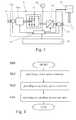
- FIG. 3shows a scheme of an auxiliary frequency converter 9 according to certain embodiments.
- the auxiliary frequency converter 9includes an exemplary ac-to-dc inverter 91 to convert a three phase ac input power received from the main generator 7 via the power lines 12 to a dc-power.
- additional electronic devices to smooth and/or store part of the dc-powersuch as capacitors are not drawn.
- the dc-poweris fed into a dc-to-ac inverter 93 .
- a photovoltaic inverter or solar inverteris used as dc-to-ac inverter 93 .
- One type of photovoltaic invertersis typically used to change direct current (dc) from a solar cell array to alternating current (ac), to synchronize with an external grid and feed the energy into the external grid, i.e. these photovoltaic inverters are arranged to operate in a grid-tie mode.
- Other types of photovoltaic invertersare adapted to build their own grid and keep it running, i.e. keep phase and frequency stable. This means, that these converter types operate in a stand-alone mode.
- the main difference between the two photovoltaic converter typesrefers to the control software running on a controller of the photovoltaic inverter such as a DSP controller.
- a commercially available photovoltaic invertersuch as the PV-PNS 04 ATL-GER of Mitsubishi Electric (e.g. available from Mitsubishi Electric Europe B.V., Photovoltaic Division, Gothaer Str. 8, D-40880 Ratingen, Germany) may be arranged to operate both in the stand-alone mode and in the grid-tie mode mainly by adaptation of the control software.
- photovoltaic inverterstypically convert dc electric power in an input voltage range of about 50 V to about 750 V and are hence well suited to convert a rectified power output of a typical wind turbine generator, such as a permanent-magnet generator.
- the digital signal controller of a photovoltaic inverteris typically already designed to effectively execute very precise algorithms required to charge an additional battery or the UPS 19 .
- the DSP controller or a controller of another type of a commercially available photovoltaic invertermay be used after some modifications as second controller 90 of the auxiliary frequency inverter 9 .
- the controller softwaremay be modified to support switching of the optional switches 95 and 96 a for disconnecting the auxiliary frequency inverter 90 from the internal supply grid 13 the main generator outputs, respectively.
- the second controllertypically detects the electric state of the internal supply grid 13 and of the power output of the main generator 7 using sensors 18 and 18 c , respectively.
- the second controller 90switches autonomously between the grid-tie mode and the stand-alone mode.
- the second controller 90autonomously switches the auxiliary frequency converter 9 into the stand-alone mode upon detecting an output voltage of the main generator 7 which is above a voltage threshold of e.g. 50 V to allow power conversion and detecting the absence of a grid on the outputs of the main converter 90 using the sensor 18 b .
- a voltage thresholde.g. 50 V
- the sensor 18 bmay also be omitted and the signal of the sensor 18 may be used to trigger the switching of the auxiliary frequency converter 9 into the stand-alone mode. Detecting no grid with the sensor 18 b typically corresponds to situation in which now power is fed into the utility grid 14 , e.g. due to an outage of the utility grid or due to a failure of the main frequency converter 8 .
- the second controller 90may directly detect the electric state of the utility grid 14 using an additional sensor.
- the auxiliary frequency converter 9typically ensures at least the supply of the main controller 10 of the wind turbine 100 and the supply of at least one pitch drive so that at least one of the rotor blades 2 can be set to a position other than the flag position.
- the rotor blade pitch anglesare adjusted such that the rotational speed of the generator rotor is within a range, for example 400-500 revolutions per minute, which is favorable for provision of electric power by the auxiliary frequency converter 9 .
- the controller 90typically stops power conversion of the auxiliary frequency converter 9 .
- the recovery of the utility grid 14is detected by an additional sensor permanently measuring the electric state of the utility grid 14 .
- This signalis typically transferred to the main controller 10 and the second controller 90 .
- the second controller 90typically switches the auxiliary frequency inverter 9 into the grid-tie mode.
- FIG. 4shows a flow diagram of a method for operating a wind turbine 100 .
- the method 1000 for operating the wind turbine 100 having a main generator 7such as e.g. a permanent-magnet generator, of a rated generator output power includes three steps.
- a main power converter 8 connected to the main generator 7 and an auxiliary power converter 9 connected to the main generator 7are provided.
- the main power converter 8 and the auxiliary power converter 9are arranged to convert the electrical output power up to a first rated converter output power and a second rated converter output power which is slower than the first rated converter output power, respectively.
- the two steps 1010 and 1020are typically already performed during assembly of the wind turbine 100 such that the main power converter 8 and the auxiliary power converter 9 are connected in parallel. Further, the order of the steps 1010 and 120 may also be reversed.
- the auxiliary power 9 converteris activated. In the activated state the auxiliary power 9 converts electrical power.
- the process of activating the auxiliary power 9typically includes preparative steps such as detecting the state of other grids prior to starting the power conversion. This will be explained in more detail by way of example mainly with respect to frequency converters as first and second power converters 8 and 9 in the following.
- FIG. 5shows a flow diagram of a method 1001 for operating a wind turbine 100 according to several embodiments.
- the second controller 90to activate the auxiliary frequency converter 9 .
- the auxiliary frequency converter 9typically monitors the output voltage of the main generator 7 , which is the input voltage of the auxiliary frequency converter 9 , and the electric state of the utility grid 14 and/or the supply grid 13 . If in a step 1120 an input voltage above a threshold of e.g. 50 V is detected, the second controller 90 decides in step 1130 into which mode auxiliary frequency converter 9 has to be set.
- the second controller 90operates as independent master. If no grid is detected, the auxiliary frequency converter 9 starts power conversion in the stand-alone mode in step 1160 . Otherwise, the second controller 90 switches the auxiliary frequency converter 9 into the grid-tie mode.
- the step 1140 of switching the auxiliary frequency converter 9 into the grid-tie modeincludes synchronizing the auxiliary frequency converter 9 to the outputs of the main frequency converter 8 or, if e.g. the main frequency converter 8 is not operating, directly to the utility grid 14 .
- the step 1100 of activating the auxiliary power converter 9may include a further step of connecting the outputs of the auxiliary frequency converter 9 to the line coupling transformer 16 and/or to the internal grid 14 , and a further step of closing the connection between the power outputs of the main generator 7 and the power inputs the auxiliary frequency converter 9 if the wind turbine 100 includes respective switches 95 , 96 and 97 as shown in FIG. 1 .
- the method 1001may already be carried out during start-up of the wind turbine 100 from standstill or during erection of the wind turbine 100 , even in the absence of the utility grid 14 .
- the second controller 90initially fed by the UPS 19 of the wind turbine 100 or an internal battery switches the auxiliary frequency converter 9 into the stand-alone mode, if the idling rotor 1 of the wind turbine delivers enough torque to rotate the generator rotor fast enough for delivering an output voltage above a certain threshold.
- the auxiliary frequency converter 9provides a power supply of the internal supply grid 13 and starts the recharging of the UPS if required.
- the main controller 10boots after the internal supply grid 13 is established.
- the main controller 10After booting, the main controller 10 typically regulates as independent master the rotor speed using the pitch drives and the yaw drive such that the power consumption and production of the wind turbine 100 is matched. Typically, the main controller 10 only issues changes of rotor blade pitch angles and azimuth angle of the nacelle, if the rotor speed is already above a certain threshold, i.e. if the generator 7 is able to produce enough electrical power. Initially, the main controller 10 may only issue the change of one pitch angle to increase the rotor speed. After recovery of the utility grid 14 , the second controller 90 typically switches the auxiliary frequency converter 9 into the grid-tie mode of synchronized power conversion and the main frequency converter 8 is activated by the main controller 10 .
- FIG. 6illustrates different methods for operating a wind turbine 100 according to further embodiments.
- typical states of the main power converter 8 and the auxiliary power converter 9are plotted as function of the absolute rotational speed of the rotor 1 and the main generators 7 rotor, respectively.
- the on-statecorresponds to the activated state, in which the respective power converter converts electrical power.
- the off-statecorresponds to the deactivated state, in which the respective power converter does not convert electrical power.
- at least the main power converter 8is a frequency converter.
- the power converters 8 and 9are typically activated or deactivated in corresponding steps 1100 , 1200 , 1300 and 1400 as indicated in the lower part of FIG. 6 .
- a change of wind speedtypically results in changing rotational speed of the rotor 1 and the main generators 7 rotor, respectively.
- the operating states of the power converters 8 and 9 of the wind turbine 100typically follow a path along the full curve from point p 1 to p 6 or along the dashed curve from point p 1 over p 4 , p 5 ′ and p 7 ′ to p 6 . For example, prior to start-up of the wind turbine 100 both converters are deactivated.
- the rotor 1After releasing the break of the wind turbine 100 , the rotor 1 starts rotating from zero velocity at point p 1 . Above a first threshold of the rotor speed n 1 reached at point p 2 , the second controller 90 of the auxiliary power converter 9 detects a voltage above a certain threshold which allows power conversion and activates the auxiliary power converter 9 . The wind turbine 100 operates now at point p 3 .
- the first threshold of the rotor speed n 1is already reached at low wind speed an idling rotor 1 . Further, the main controller typically starts to speed up the rotor 1 e.g. by changing the pitch angle of the rotor blades 2 .
- the main controller 10activates the main power converter 8 and disconnects the auxiliary power converter 9 by opening the switch 96 shown in FIG. 1 .
- the second controller 90deactivates the auxiliary power converter 9 after detecting a too low, i.e. zero, input voltage.
- the wind turbine 100operates now at point p 5 ′ in which only the main power converter 8 converts power.
- the internal supply grid 13is also fed by the main power converter 8 between the point p 5 ′ and p 7 ′.
- the main controller 10closes again the switch 96 and the second controller 90 activates the auxiliary power converter 9 again resulting in an operating state of point p 7 ′.
- the maximum power the wind turbine 100 can feed into the utility grid 14is reached at a fourth threshold of the rotor speed n 4 at point p 6 .
- the fourth threshold of the rotor speed n 4typically corresponds to a power production of the main generator 7 at the rated generator output power. Therefore, the main controller 10 regulates the rotor speed typically such, that the fourth threshold n 4 is at most only exceeded for a short time to avoid overloading. If the rotor speed decreases, e.g.
- the auxiliary power converter 9is deactivated at point p 7 ′.
- An even further decreasing rotor speedmay result in activating the auxiliary power converter 9 and deactivating the main power converter 9 at point p 5 ′ and finally in deactivating the auxiliary power converter 9 at point p 3 .
- the auxiliary power converter 9is not deactivated and/or activated above the first threshold n 1 . This simplifies the operating control of the wind turbine 100 . Further, this example goes without the additional power switch 95 shown in FIG. 1 .
- the wind turbine 100is typically also able to deliver electric power to the utility grid 14 at a wind speed corresponding to the rotor speed n 2 below which power conversion with the main power converter 8 is not efficient e.g. due to the losses of the cooling system.
- the operating range of the wind turbine 100can be extended.
- FIG. 7showing a flow diagram of a further method for operating a wind turbine 100 according to several embodiments will be explained.
- the method 1002is typically carried during low or lowering wind speed and may corresponds to a path from point p 5 ′ to p 1 or a path from point p 5 to p 1 of FIG. 6 with operating utility grid 14 .
- the auxiliary frequency converter 9is activated in step 1100 , if the wind turbine 100 starts from a state corresponding to a point on the dashed curve of FIG. 6 .
- the step 1100includes a step 1110 of connecting the auxiliary frequency converter 9 to the outputs of the main generator 7 and a step 1140 of switching the auxiliary frequency converter 9 into the grid-tie mode.
- the step 1100is autonomously performed by the second controller 90 after detecting a high enough input voltage provided by the main generator 7 . If the wind turbine 100 starts from a state corresponding to a point on the full curve of FIG. 6 , the step 1100 is omitted. Subsequently, the main frequency converter 8 is deactivated in step 1300 . In step 1320 , the main controller 10 starts regulating the speed of the rotor 1 by issuing the blade pitch angles such that the power production of the wind turbine 100 is at maximum. This typically allows feeding of electrical power into the utility grid 14 .
- the auxiliary frequency converter 9When calm weather of extremely low wind speed sets in, the rotor speed becomes eventually very low. If a too low rotor speed for power conversion of the auxiliary frequency converter 9 is detected in a step 1350 , the auxiliary frequency converter 9 is deactivated in a step 1400 . For safety reasons, signaling devices and obstruction lights are further supplied by the uninterruptible power supply 19 of the wind turbine 100 . Typically, the too low rotor speed corresponding to a too low rotational speed of the generator rotor for power conversion is independently detected by the second controller 90 , e.g. by measuring the output voltage and/or the frequency of the main generator 7 .
- the method 1002is typically carried out during an outage of the utility grid 14 and may correspond to a path from point p 5 ′ to p 1 or a path from point p 5 to p 1 of FIG. 6 without operating utility grid 14 .
- the rotor 1 of the wind turbine 100is decelerated e.g. by changing the blade pitch angles in a step 1070 .
- the auxiliary frequency converter 9is activated in step 1100 , if the wind turbine 100 starts from a state corresponding to a point on the dashed curve of FIG.
- the step 1100typically includes a step 1110 of connecting the auxiliary frequency converter 9 to the outputs of the main generator 7 and a step 1140 of switching the auxiliary frequency converter 9 into the grid-tie mode, in which the auxiliary frequency converter 9 is synchronized with the main frequency converter 8 .
- the step 1100is autonomously performed by the second controller 90 after detecting a high enough input voltage provided by the main generator 7 . If the wind turbine 100 starts from a state corresponding to a point on the full curve of FIG. 6 , the step 1100 is omitted. Subsequently, the main frequency converter 8 is deactivated in step 1300 . Since the second controller 90 can no longer detect another grid, it switches the auxiliary frequency converter 9 into the stand-alone mode in step 1160 to provide a power supply for the internal supply grid 13 . Finally, the power production and power consumption of the wind turbine 100 is matched in a step 1500 . This is typically achieved by independent operating of the main controller 10 and the second controller 90 .
- the main controller 10typically measures the rotor speed (or the speed of the generator rotor) and regulates the rotor speed to a constant value by issuing commands for changing the pitch angle of at least one rotor blade 2 . This ensures the balance between the power consumption and the power production of the wind turbine 100 .
Landscapes
- Engineering & Computer Science (AREA)
- Life Sciences & Earth Sciences (AREA)
- Sustainable Development (AREA)
- Sustainable Energy (AREA)
- Chemical & Material Sciences (AREA)
- Combustion & Propulsion (AREA)
- Mechanical Engineering (AREA)
- General Engineering & Computer Science (AREA)
- Power Engineering (AREA)
- Control Of Eletrric Generators (AREA)
Abstract
Description
Claims (16)
Priority Applications (4)
| Application Number | Priority Date | Filing Date | Title |
|---|---|---|---|
| US12/206,073US8188610B2 (en) | 2008-09-08 | 2008-09-08 | Wind turbine having a main power converter and an auxiliary power converter and a method for the control thereof |
| DK09168541.2TDK2161443T3 (en) | 2008-09-08 | 2009-08-25 | Wind turbine having a main power converter and an auxiliary power converter and a method of controlling thereof |
| EP09168541.2AEP2161443B1 (en) | 2008-09-08 | 2009-08-25 | A wind turbine having a main power converter and an auxiliary power converter and a method for the control thereof |
| CN200910173065.5ACN101672252B (en) | 2008-09-08 | 2009-09-08 | Wind turbine and method for control thereof |
Applications Claiming Priority (1)
| Application Number | Priority Date | Filing Date | Title |
|---|---|---|---|
| US12/206,073US8188610B2 (en) | 2008-09-08 | 2008-09-08 | Wind turbine having a main power converter and an auxiliary power converter and a method for the control thereof |
Publications (2)
| Publication Number | Publication Date |
|---|---|
| US20100060000A1 US20100060000A1 (en) | 2010-03-11 |
| US8188610B2true US8188610B2 (en) | 2012-05-29 |
Family
ID=41467148
Family Applications (1)
| Application Number | Title | Priority Date | Filing Date |
|---|---|---|---|
| US12/206,073Expired - Fee RelatedUS8188610B2 (en) | 2008-09-08 | 2008-09-08 | Wind turbine having a main power converter and an auxiliary power converter and a method for the control thereof |
Country Status (4)
| Country | Link |
|---|---|
| US (1) | US8188610B2 (en) |
| EP (1) | EP2161443B1 (en) |
| CN (1) | CN101672252B (en) |
| DK (1) | DK2161443T3 (en) |
Cited By (68)
| Publication number | Priority date | Publication date | Assignee | Title |
|---|---|---|---|---|
| US20110062708A1 (en)* | 2009-09-17 | 2011-03-17 | General Electric Company | Generator control having power grid communications |
| US20110175355A1 (en)* | 2008-09-19 | 2011-07-21 | Vestas Wind Systems A/S | Turbine farm having an auxiliary power supply |
| US20120068461A1 (en)* | 2008-10-14 | 2012-03-22 | Henning Luetze | Wind Energy System |
| US20120221159A1 (en)* | 2011-02-25 | 2012-08-30 | Henrik Steengaard Olesen | Wind turbine |
| US20120217749A1 (en)* | 2009-11-03 | 2012-08-30 | Trevi Energy S.P.A | Control system for wind farms with aerogenerations provided with modular converters |
| US20120256490A1 (en)* | 2011-04-07 | 2012-10-11 | Yongchun Zheng | Integrated Expandable Grid-Ready Solar Electrical Generator |
| US20130214535A1 (en)* | 2010-08-23 | 2013-08-22 | Per Brath | Method of operating a wind turbine and wind turbine |
| US20130264882A1 (en)* | 2012-04-04 | 2013-10-10 | Gamesa Innovation & Technology, S.L. | Power generation and distribution system for a wind turbine |
| US20140015252A1 (en)* | 2011-03-29 | 2014-01-16 | General Electric Company | Methods for adjusting the power output of a wind turbine |
| US8824178B1 (en)* | 2009-12-31 | 2014-09-02 | Solarbridge Technologies, Inc. | Parallel power converter topology |
| US20140291990A1 (en)* | 2013-03-27 | 2014-10-02 | Alstom Renovables España, S.L. | System for providing electrical power to a wind turbine component |
| US20140361725A1 (en)* | 2012-02-28 | 2014-12-11 | Omron Corporation | Power storage control device, power storage control device control method, program and power storage system |
| US20150108761A1 (en)* | 2013-10-18 | 2015-04-23 | Abb Technology Ag | Turbine-Generator System with DC Output |
| US9334749B2 (en) | 2013-10-18 | 2016-05-10 | Abb Technology Ag | Auxiliary power system for turbine-based energy generation system |
| US9344001B2 (en) | 2013-02-06 | 2016-05-17 | Control Techniques Limited | Inverter circuits for electrical machines |
| US20160373006A9 (en)* | 2007-12-05 | 2016-12-22 | Meir Adest | Testing of a Photovoltaic Panel |
| US9593672B2 (en) | 2013-08-07 | 2017-03-14 | Siemens Aktiengesellschaft | Isochronous wind turbine generator capable of stand-alone operation |
| US9614457B2 (en) | 2013-10-18 | 2017-04-04 | Abb Schweiz Ag | Modular thyristor-based rectifier circuits |
| US20170359011A1 (en)* | 2016-06-08 | 2017-12-14 | Hamilton Sundstrand Corporation | Reconfigurable multi-permanent magnet generator based power generating system |
| US9948233B2 (en) | 2006-12-06 | 2018-04-17 | Solaredge Technologies Ltd. | Distributed power harvesting systems using DC power sources |
| US9960731B2 (en) | 2006-12-06 | 2018-05-01 | Solaredge Technologies Ltd. | Pairing of components in a direct current distributed power generation system |
| US9960667B2 (en) | 2006-12-06 | 2018-05-01 | Solaredge Technologies Ltd. | System and method for protection during inverter shutdown in distributed power installations |
| US9979280B2 (en) | 2007-12-05 | 2018-05-22 | Solaredge Technologies Ltd. | Parallel connected inverters |
| US10007288B2 (en) | 2012-03-05 | 2018-06-26 | Solaredge Technologies Ltd. | Direct current link circuit |
| US10097007B2 (en) | 2006-12-06 | 2018-10-09 | Solaredge Technologies Ltd. | Method for distributed power harvesting using DC power sources |
| US20180306169A1 (en)* | 2017-04-24 | 2018-10-25 | General Electric Company | Method of Operating a Wind Turbine System Including an Energy Storage System |
| US10116217B2 (en) | 2007-08-06 | 2018-10-30 | Solaredge Technologies Ltd. | Digital average input current control in power converter |
| US10184965B2 (en) | 2006-12-06 | 2019-01-22 | Solaredge Technologies Ltd. | Monitoring of distributed power harvesting systems using DC power sources |
| US10230245B2 (en) | 2006-12-06 | 2019-03-12 | Solaredge Technologies Ltd | Battery power delivery module |
| US10230310B2 (en) | 2016-04-05 | 2019-03-12 | Solaredge Technologies Ltd | Safety switch for photovoltaic systems |
| US10381977B2 (en) | 2012-01-30 | 2019-08-13 | Solaredge Technologies Ltd | Photovoltaic panel circuitry |
| US10396662B2 (en) | 2011-09-12 | 2019-08-27 | Solaredge Technologies Ltd | Direct current link circuit |
| US10447150B2 (en) | 2006-12-06 | 2019-10-15 | Solaredge Technologies Ltd. | Distributed power harvesting systems using DC power sources |
| US10468878B2 (en) | 2008-05-05 | 2019-11-05 | Solaredge Technologies Ltd. | Direct current power combiner |
| US10608553B2 (en) | 2012-01-30 | 2020-03-31 | Solaredge Technologies Ltd. | Maximizing power in a photovoltaic distributed power system |
| US20200124027A1 (en)* | 2017-02-07 | 2020-04-23 | Siemens Gamesa Renewable Energy A/S | Wind turbine with an auxiliary power supply |
| US10637393B2 (en) | 2006-12-06 | 2020-04-28 | Solaredge Technologies Ltd. | Distributed power harvesting systems using DC power sources |
| US10651647B2 (en) | 2013-03-15 | 2020-05-12 | Solaredge Technologies Ltd. | Bypass mechanism |
| US10666125B2 (en) | 2011-01-12 | 2020-05-26 | Solaredge Technologies Ltd. | Serially connected inverters |
| US10673229B2 (en) | 2010-11-09 | 2020-06-02 | Solaredge Technologies Ltd. | Arc detection and prevention in a power generation system |
| US10673222B2 (en) | 2010-11-09 | 2020-06-02 | Solaredge Technologies Ltd. | Arc detection and prevention in a power generation system |
| US10778025B2 (en) | 2013-03-14 | 2020-09-15 | Solaredge Technologies Ltd. | Method and apparatus for storing and depleting energy |
| US10931119B2 (en) | 2012-01-11 | 2021-02-23 | Solaredge Technologies Ltd. | Photovoltaic module |
| US10931228B2 (en) | 2010-11-09 | 2021-02-23 | Solaredge Technologies Ftd. | Arc detection and prevention in a power generation system |
| US10969412B2 (en) | 2009-05-26 | 2021-04-06 | Solaredge Technologies Ltd. | Theft detection and prevention in a power generation system |
| US10992238B2 (en) | 2012-01-30 | 2021-04-27 | Solaredge Technologies Ltd. | Maximizing power in a photovoltaic distributed power system |
| US11018623B2 (en) | 2016-04-05 | 2021-05-25 | Solaredge Technologies Ltd. | Safety switch for photovoltaic systems |
| US11177663B2 (en) | 2016-04-05 | 2021-11-16 | Solaredge Technologies Ltd. | Chain of power devices |
| US11177768B2 (en) | 2012-06-04 | 2021-11-16 | Solaredge Technologies Ltd. | Integrated photovoltaic panel circuitry |
| US11264947B2 (en) | 2007-12-05 | 2022-03-01 | Solaredge Technologies Ltd. | Testing of a photovoltaic panel |
| US11296650B2 (en) | 2006-12-06 | 2022-04-05 | Solaredge Technologies Ltd. | System and method for protection during inverter shutdown in distributed power installations |
| US11309832B2 (en) | 2006-12-06 | 2022-04-19 | Solaredge Technologies Ltd. | Distributed power harvesting systems using DC power sources |
| US11353004B2 (en)* | 2017-06-13 | 2022-06-07 | Wobben Properties Gmbh | Wind turbine comprising a gearless generator and a generator filter |
| US11569659B2 (en) | 2006-12-06 | 2023-01-31 | Solaredge Technologies Ltd. | Distributed power harvesting systems using DC power sources |
| US11569660B2 (en) | 2006-12-06 | 2023-01-31 | Solaredge Technologies Ltd. | Distributed power harvesting systems using DC power sources |
| US11579235B2 (en) | 2006-12-06 | 2023-02-14 | Solaredge Technologies Ltd. | Safety mechanisms, wake up and shutdown methods in distributed power installations |
| EP4194685A1 (en)* | 2021-12-07 | 2023-06-14 | General Electric Renovables España S.L. | A method for operating a wind turbine and a wind turbine |
| US11687112B2 (en) | 2006-12-06 | 2023-06-27 | Solaredge Technologies Ltd. | Distributed power harvesting systems using DC power sources |
| US11728768B2 (en) | 2006-12-06 | 2023-08-15 | Solaredge Technologies Ltd. | Pairing of components in a direct current distributed power generation system |
| US11735910B2 (en) | 2006-12-06 | 2023-08-22 | Solaredge Technologies Ltd. | Distributed power system using direct current power sources |
| US11855231B2 (en) | 2006-12-06 | 2023-12-26 | Solaredge Technologies Ltd. | Distributed power harvesting systems using DC power sources |
| US11881814B2 (en) | 2005-12-05 | 2024-01-23 | Solaredge Technologies Ltd. | Testing of a photovoltaic panel |
| US11888387B2 (en) | 2006-12-06 | 2024-01-30 | Solaredge Technologies Ltd. | Safety mechanisms, wake up and shutdown methods in distributed power installations |
| EP4390113A1 (en)* | 2022-12-19 | 2024-06-26 | Nordex Energy SE & Co. KG | A method for yaw control of a wind turbine and a wind turbine having a yaw control |
| US12027849B2 (en) | 2006-12-06 | 2024-07-02 | Solaredge Technologies Ltd. | Distributed power system using direct current power sources |
| US12057807B2 (en) | 2016-04-05 | 2024-08-06 | Solaredge Technologies Ltd. | Chain of power devices |
| US20250223948A1 (en)* | 2024-01-10 | 2025-07-10 | Siemens Gamesa Renewable Energy A/S | Servicing of a wind turbine component |
| US12418177B2 (en) | 2009-10-24 | 2025-09-16 | Solaredge Technologies Ltd. | Distributed power system using direct current power sources |
Families Citing this family (65)
| Publication number | Priority date | Publication date | Assignee | Title |
|---|---|---|---|---|
| WO2009073867A1 (en) | 2007-12-05 | 2009-06-11 | Solaredge, Ltd. | Parallel connected inverters |
| US9291696B2 (en) | 2007-12-05 | 2016-03-22 | Solaredge Technologies Ltd. | Photovoltaic system power tracking method |
| US8111052B2 (en) | 2008-03-24 | 2012-02-07 | Solaredge Technologies Ltd. | Zero voltage switching |
| CN102365593A (en)* | 2009-02-03 | 2012-02-29 | 东能源公司 | Distributed electrical power production system and method of control thereof |
| CA2762184A1 (en) | 2009-05-12 | 2010-11-18 | Icr Turbine Engine Corporation | Gas turbine energy storage and conversion system |
| JP5022451B2 (en)* | 2009-06-05 | 2012-09-12 | 三菱重工業株式会社 | Wind power generator, control method therefor, and wind power generation system |
| DE102009027981B4 (en)* | 2009-07-23 | 2011-04-28 | Suzlon Energy Gmbh | Method for operating a wind turbine connected to a power grid as well as wind turbine suitable for carrying out the method |
| WO2011023774A2 (en)* | 2009-08-28 | 2011-03-03 | Vestas Wind Systems A/S | Wind turbine data acquisition system |
| US8860236B2 (en)* | 2009-10-19 | 2014-10-14 | Uwm Research Foundation, Inc. | Wind energy power conversion system reducing gearbox stress and improving power stability |
| US8866334B2 (en) | 2010-03-02 | 2014-10-21 | Icr Turbine Engine Corporation | Dispatchable power from a renewable energy facility |
| US8984895B2 (en) | 2010-07-09 | 2015-03-24 | Icr Turbine Engine Corporation | Metallic ceramic spool for a gas turbine engine |
| CA2813680A1 (en) | 2010-09-03 | 2012-03-08 | Icr Turbine Engine Corporation | Gas turbine engine configurations |
| EP2458205B1 (en)* | 2010-11-26 | 2016-10-19 | Siemens Aktiengesellschaft | Method and system for controlling an electric device of a wind turbine |
| GB2486408A (en) | 2010-12-09 | 2012-06-20 | Solaredge Technologies Ltd | Disconnection of a string carrying direct current |
| US8624437B2 (en)* | 2010-12-28 | 2014-01-07 | Vestas Wind Systems A/S | Power conversion system and method |
| US8631275B2 (en) | 2010-12-28 | 2014-01-14 | Vestas Wind Systems A/S | Controller arrangement of an electrical power transfer system of a wind turbine |
| US8957535B2 (en)* | 2011-01-17 | 2015-02-17 | Vestas Wind Systems A/S | Fault tolerant wind turbine converter |
| CN102182631A (en)* | 2011-05-03 | 2011-09-14 | 苏州能健电气有限公司 | Main control device of wind power generation equipment |
| US9051873B2 (en) | 2011-05-20 | 2015-06-09 | Icr Turbine Engine Corporation | Ceramic-to-metal turbine shaft attachment |
| DE102011105854B4 (en) | 2011-06-03 | 2013-04-11 | Nordex Energy Gmbh | Method for operating a wind energy plant in the event of a grid fault and such a wind turbine |
| EP2555141A1 (en)* | 2011-08-03 | 2013-02-06 | Alcatel Lucent | A method, a system, a server, a control element, a computer program and a computer program product for operating a power grid having decentralized control elements |
| EP2565443A1 (en) | 2011-09-05 | 2013-03-06 | XEMC Darwind B.V. | Generating auxiliary power for a wind turbine |
| JP5834790B2 (en) | 2011-11-09 | 2015-12-24 | ブラザー工業株式会社 | Power supply system, image forming apparatus equipped with the same power supply system, and control method of power supply system |
| DE102011121707A1 (en)* | 2011-12-20 | 2013-07-04 | Airbus Operations Gmbh | Electrical system for an aircraft |
| DE102011122433A1 (en)* | 2011-12-24 | 2013-06-27 | Robert Bosch Gmbh | Wind turbine |
| WO2013108288A1 (en)* | 2012-01-18 | 2013-07-25 | 株式会社 日立製作所 | Wind power generating system |
| WO2013114368A2 (en)* | 2012-01-31 | 2013-08-08 | Birdsvision Ltd | Method and system for detection and deterrence of flying animals and prevention of collisions with wind turbines |
| DE102012204239A1 (en) | 2012-03-16 | 2013-09-19 | Wobben Properties Gmbh | Method for controlling a wind energy plant |
| US10251316B1 (en) | 2012-05-29 | 2019-04-02 | Mistbox, Inc. | Air conditioner mister, apparatus and method |
| US9198980B1 (en) | 2012-05-29 | 2015-12-01 | Environmyst LLC | Air conditioner mister, apparatus and method |
| US10094288B2 (en) | 2012-07-24 | 2018-10-09 | Icr Turbine Engine Corporation | Ceramic-to-metal turbine volute attachment for a gas turbine engine |
| US20140062425A1 (en)* | 2012-08-31 | 2014-03-06 | General Electric Company | System and method for interfacing variable speed generators to a power grid |
| DK177684B1 (en)* | 2012-12-21 | 2014-03-03 | Envision Energy Denmark Aps | Wind turbine having a HTS generator with a plurality of phases |
| JP6020219B2 (en)* | 2013-02-06 | 2016-11-02 | ブラザー工業株式会社 | Power system |
| JP6044380B2 (en) | 2013-02-18 | 2016-12-14 | ブラザー工業株式会社 | Power supply system and image forming apparatus equipped with the power supply system |
| US9941813B2 (en) | 2013-03-14 | 2018-04-10 | Solaredge Technologies Ltd. | High frequency multi-level inverter |
| AT514239B1 (en)* | 2013-04-18 | 2015-02-15 | Set Sustainable Energy Technologies Gmbh | Drive and method for operating such a drive |
| US9018783B2 (en)* | 2013-05-21 | 2015-04-28 | General Electric Company | Doubly-fed induction generator wind turbine system having solid-state stator switch |
| WO2015073037A1 (en)* | 2013-11-15 | 2015-05-21 | University Of Washington | Energy recovery systems for ventilation exhausts and associated apparatuses and methods |
| US9337685B2 (en)* | 2013-12-23 | 2016-05-10 | General Electric Company | Optimized filter for battery energy storage on alternate energy systems |
| US9735581B2 (en)* | 2014-03-14 | 2017-08-15 | Abb Schweiz Ag | Method and apparatus for obtaining electricity from offshore wind turbines |
| US9859806B2 (en)* | 2014-03-14 | 2018-01-02 | Abb Research Ltd. | Method and apparatus for obtaining electricity from offshore wind turbines |
| US9318974B2 (en) | 2014-03-26 | 2016-04-19 | Solaredge Technologies Ltd. | Multi-level inverter with flying capacitor topology |
| US10250042B2 (en)* | 2014-10-27 | 2019-04-02 | Vestas Wind Systems A/S | Wind-turbine converter control for modular string converters |
| EP3136549A1 (en) | 2015-08-24 | 2017-03-01 | Siemens Aktiengesellschaft | Synchronous reluctance machine |
| GB2545493A (en)* | 2015-12-18 | 2017-06-21 | Moog Unna Gmbh | Wind turbine diagnostic apparatus |
| US11081608B2 (en) | 2016-03-03 | 2021-08-03 | Solaredge Technologies Ltd. | Apparatus and method for determining an order of power devices in power generation systems |
| CN107153212B (en) | 2016-03-03 | 2023-07-28 | 太阳能安吉科技有限公司 | Method for mapping a power generation facility |
| US10599113B2 (en) | 2016-03-03 | 2020-03-24 | Solaredge Technologies Ltd. | Apparatus and method for determining an order of power devices in power generation systems |
| US20170353094A1 (en)* | 2016-06-07 | 2017-12-07 | James Sutliff | Generator system for energy conservation |
| US12362566B2 (en) | 2016-09-19 | 2025-07-15 | Flexgen Power Systems, Llc | Systems and methods for rapid activation and synchronization of dispatchable power sources |
| GB2553872B (en)* | 2016-09-19 | 2018-10-03 | Flexgen Power Systems Inc | Systems and methods for rapid activation of dispatchable power sources |
| EP3316438A1 (en)* | 2016-10-26 | 2018-05-02 | MHI Vestas Offshore Wind A/S | Controlling power exchange from self-commutated converters |
| DE102016124840A1 (en) | 2016-12-19 | 2018-06-21 | Wobben Properties Gmbh | Method for controlling a network rebuilding |
| BR112019022448B1 (en)* | 2017-04-28 | 2023-12-19 | General Electric Company | POWER GENERATION SYSTEM AND METHOD FOR IMPROVING ELECTRICAL POWER PRODUCTION BY A POWER GENERATION SYSTEM |
| EP3635247B1 (en)* | 2017-06-08 | 2023-07-19 | Vestas Wind Systems A/S | Operation of a wind turbine during grid loss using a power storage unit |
| CN107313894B (en)* | 2017-08-30 | 2019-05-28 | 广州市风力新能源科技有限公司 | A kind of miniature wind power generation system |
| WO2019059918A1 (en)* | 2017-09-22 | 2019-03-28 | Sutliff James | Generator system for energy conservation |
| CN109931217B (en) | 2017-12-15 | 2020-05-12 | 新疆金风科技股份有限公司 | Wind generating set shutdown control method and system |
| US10689999B2 (en)* | 2018-02-22 | 2020-06-23 | Ge Aviation Systems, Llc | Power generation system |
| FR3082069B1 (en)* | 2018-05-29 | 2020-05-01 | Safran | SYSTEM FOR SYNCHRONIZING COUPLED ENERGY SOURCES OF AN AIRCRAFT |
| ES2928722T3 (en)* | 2018-08-29 | 2022-11-22 | General Electric Renovables Espana Sl | Wind Turbine Hub Rotation Procedures |
| US10975732B2 (en)* | 2019-04-04 | 2021-04-13 | General Electric Company | Rotor turning device for balancing a wind turbine rotor |
| US10742149B1 (en)* | 2019-04-22 | 2020-08-11 | General Electric Company | System and method for reactive power control of a wind turbine by varying switching frequency of rotor side converter |
| US20220112836A1 (en)* | 2020-10-08 | 2022-04-14 | Alternative Sustainability IP LLC | Energy capture device |
Citations (6)
| Publication number | Priority date | Publication date | Assignee | Title |
|---|---|---|---|---|
| WO2005113964A1 (en) | 2004-05-18 | 2005-12-01 | Nordex Energy Gmbh | Wind power installation having an auxiliary generator and method for the control thereof |
| US7038330B2 (en)* | 2004-04-23 | 2006-05-02 | Rwe Piller Gmbh | Protection for wind power station |
| US7071579B2 (en)* | 2002-06-07 | 2006-07-04 | Global Energyconcepts,Llc | Wind farm electrical system |
| US7205676B2 (en)* | 2004-01-08 | 2007-04-17 | Hitachi, Ltd. | Wind turbine generator system |
| US7253537B2 (en)* | 2005-12-08 | 2007-08-07 | General Electric Company | System and method of operating double fed induction generators |
| US7579702B2 (en)* | 2005-12-30 | 2009-08-25 | Korea Electrotechnology Research Institute | Electric power converting device and power converting method for controlling doubly-fed induction generator |
Family Cites Families (3)
| Publication number | Priority date | Publication date | Assignee | Title |
|---|---|---|---|---|
| US5907192A (en)* | 1997-06-09 | 1999-05-25 | General Electric Company | Method and system for wind turbine braking |
| CA2613556A1 (en)* | 2005-07-01 | 2007-01-11 | Vestas Wind Systems A/S | A variable rotor speed wind turbine, wind park, method of transmitting electric power and method of servicing or inspecting a variable rotor speed wind turbine |
| FI119086B (en)* | 2006-11-06 | 2008-07-15 | Abb Oy | Method and arrangement for a wind turbine |
- 2008
- 2008-09-08USUS12/206,073patent/US8188610B2/ennot_activeExpired - Fee Related
- 2009
- 2009-08-25DKDK09168541.2Tpatent/DK2161443T3/enactive
- 2009-08-25EPEP09168541.2Apatent/EP2161443B1/ennot_activeNot-in-force
- 2009-09-08CNCN200910173065.5Apatent/CN101672252B/ennot_activeExpired - Fee Related
Patent Citations (6)
| Publication number | Priority date | Publication date | Assignee | Title |
|---|---|---|---|---|
| US7071579B2 (en)* | 2002-06-07 | 2006-07-04 | Global Energyconcepts,Llc | Wind farm electrical system |
| US7205676B2 (en)* | 2004-01-08 | 2007-04-17 | Hitachi, Ltd. | Wind turbine generator system |
| US7038330B2 (en)* | 2004-04-23 | 2006-05-02 | Rwe Piller Gmbh | Protection for wind power station |
| WO2005113964A1 (en) | 2004-05-18 | 2005-12-01 | Nordex Energy Gmbh | Wind power installation having an auxiliary generator and method for the control thereof |
| US7253537B2 (en)* | 2005-12-08 | 2007-08-07 | General Electric Company | System and method of operating double fed induction generators |
| US7579702B2 (en)* | 2005-12-30 | 2009-08-25 | Korea Electrotechnology Research Institute | Electric power converting device and power converting method for controlling doubly-fed induction generator |
Cited By (142)
| Publication number | Priority date | Publication date | Assignee | Title |
|---|---|---|---|---|
| US11881814B2 (en) | 2005-12-05 | 2024-01-23 | Solaredge Technologies Ltd. | Testing of a photovoltaic panel |
| US11598652B2 (en) | 2006-12-06 | 2023-03-07 | Solaredge Technologies Ltd. | Monitoring of distributed power harvesting systems using DC power sources |
| US11855231B2 (en) | 2006-12-06 | 2023-12-26 | Solaredge Technologies Ltd. | Distributed power harvesting systems using DC power sources |
| US12281919B2 (en) | 2006-12-06 | 2025-04-22 | Solaredge Technologies Ltd. | Monitoring of distributed power harvesting systems using DC power sources |
| US12276997B2 (en) | 2006-12-06 | 2025-04-15 | Solaredge Technologies Ltd. | Distributed power harvesting systems using DC power sources |
| US12224706B2 (en) | 2006-12-06 | 2025-02-11 | Solaredge Technologies Ltd. | Pairing of components in a direct current distributed power generation system |
| US12107417B2 (en) | 2006-12-06 | 2024-10-01 | Solaredge Technologies Ltd. | Distributed power harvesting systems using DC power sources |
| US12068599B2 (en) | 2006-12-06 | 2024-08-20 | Solaredge Technologies Ltd. | System and method for protection during inverter shutdown in distributed power installations |
| US12046940B2 (en) | 2006-12-06 | 2024-07-23 | Solaredge Technologies Ltd. | Battery power control |
| US12032080B2 (en) | 2006-12-06 | 2024-07-09 | Solaredge Technologies Ltd. | Safety mechanisms, wake up and shutdown methods in distributed power installations |
| US12027970B2 (en) | 2006-12-06 | 2024-07-02 | Solaredge Technologies Ltd. | Safety mechanisms, wake up and shutdown methods in distributed power installations |
| US12027849B2 (en) | 2006-12-06 | 2024-07-02 | Solaredge Technologies Ltd. | Distributed power system using direct current power sources |
| US11962243B2 (en) | 2006-12-06 | 2024-04-16 | Solaredge Technologies Ltd. | Method for distributed power harvesting using DC power sources |
| US11961922B2 (en) | 2006-12-06 | 2024-04-16 | Solaredge Technologies Ltd. | Distributed power harvesting systems using DC power sources |
| US11594881B2 (en) | 2006-12-06 | 2023-02-28 | Solaredge Technologies Ltd. | Distributed power harvesting systems using DC power sources |
| US12388492B2 (en) | 2006-12-06 | 2025-08-12 | Solaredge Technologies Ltd. | Safety mechanisms, wake up and shutdown methods in distributed power installations |
| US11594880B2 (en) | 2006-12-06 | 2023-02-28 | Solaredge Technologies Ltd. | Distributed power harvesting systems using DC power sources |
| US11735910B2 (en) | 2006-12-06 | 2023-08-22 | Solaredge Technologies Ltd. | Distributed power system using direct current power sources |
| US11728768B2 (en) | 2006-12-06 | 2023-08-15 | Solaredge Technologies Ltd. | Pairing of components in a direct current distributed power generation system |
| US11687112B2 (en) | 2006-12-06 | 2023-06-27 | Solaredge Technologies Ltd. | Distributed power harvesting systems using DC power sources |
| US11682918B2 (en) | 2006-12-06 | 2023-06-20 | Solaredge Technologies Ltd. | Battery power delivery module |
| US11658482B2 (en) | 2006-12-06 | 2023-05-23 | Solaredge Technologies Ltd. | Distributed power harvesting systems using DC power sources |
| US10637393B2 (en) | 2006-12-06 | 2020-04-28 | Solaredge Technologies Ltd. | Distributed power harvesting systems using DC power sources |
| US12316274B2 (en) | 2006-12-06 | 2025-05-27 | Solaredge Technologies Ltd. | Pairing of components in a direct current distributed power generation system |
| US11594882B2 (en) | 2006-12-06 | 2023-02-28 | Solaredge Technologies Ltd. | Distributed power harvesting systems using DC power sources |
| US11888387B2 (en) | 2006-12-06 | 2024-01-30 | Solaredge Technologies Ltd. | Safety mechanisms, wake up and shutdown methods in distributed power installations |
| US11579235B2 (en) | 2006-12-06 | 2023-02-14 | Solaredge Technologies Ltd. | Safety mechanisms, wake up and shutdown methods in distributed power installations |
| US11575261B2 (en) | 2006-12-06 | 2023-02-07 | Solaredge Technologies Ltd. | Distributed power harvesting systems using DC power sources |
| US11575260B2 (en) | 2006-12-06 | 2023-02-07 | Solaredge Technologies Ltd. | Distributed power harvesting systems using DC power sources |
| US9948233B2 (en) | 2006-12-06 | 2018-04-17 | Solaredge Technologies Ltd. | Distributed power harvesting systems using DC power sources |
| US9960731B2 (en) | 2006-12-06 | 2018-05-01 | Solaredge Technologies Ltd. | Pairing of components in a direct current distributed power generation system |
| US9960667B2 (en) | 2006-12-06 | 2018-05-01 | Solaredge Technologies Ltd. | System and method for protection during inverter shutdown in distributed power installations |
| US11569660B2 (en) | 2006-12-06 | 2023-01-31 | Solaredge Technologies Ltd. | Distributed power harvesting systems using DC power sources |
| US11569659B2 (en) | 2006-12-06 | 2023-01-31 | Solaredge Technologies Ltd. | Distributed power harvesting systems using DC power sources |
| US10097007B2 (en) | 2006-12-06 | 2018-10-09 | Solaredge Technologies Ltd. | Method for distributed power harvesting using DC power sources |
| US11476799B2 (en) | 2006-12-06 | 2022-10-18 | Solaredge Technologies Ltd. | Distributed power harvesting systems using DC power sources |
| US11309832B2 (en) | 2006-12-06 | 2022-04-19 | Solaredge Technologies Ltd. | Distributed power harvesting systems using DC power sources |
| US10184965B2 (en) | 2006-12-06 | 2019-01-22 | Solaredge Technologies Ltd. | Monitoring of distributed power harvesting systems using DC power sources |
| US10230245B2 (en) | 2006-12-06 | 2019-03-12 | Solaredge Technologies Ltd | Battery power delivery module |
| US11296650B2 (en) | 2006-12-06 | 2022-04-05 | Solaredge Technologies Ltd. | System and method for protection during inverter shutdown in distributed power installations |
| US11183922B2 (en) | 2006-12-06 | 2021-11-23 | Solaredge Technologies Ltd. | Distributed power harvesting systems using DC power sources |
| US11063440B2 (en) | 2006-12-06 | 2021-07-13 | Solaredge Technologies Ltd. | Method for distributed power harvesting using DC power sources |
| US10447150B2 (en) | 2006-12-06 | 2019-10-15 | Solaredge Technologies Ltd. | Distributed power harvesting systems using DC power sources |
| US11043820B2 (en) | 2006-12-06 | 2021-06-22 | Solaredge Technologies Ltd. | Battery power delivery module |
| US11031861B2 (en) | 2006-12-06 | 2021-06-08 | Solaredge Technologies Ltd. | System and method for protection during inverter shutdown in distributed power installations |
| US10673253B2 (en) | 2006-12-06 | 2020-06-02 | Solaredge Technologies Ltd. | Battery power delivery module |
| US10116217B2 (en) | 2007-08-06 | 2018-10-30 | Solaredge Technologies Ltd. | Digital average input current control in power converter |
| US10516336B2 (en) | 2007-08-06 | 2019-12-24 | Solaredge Technologies Ltd. | Digital average input current control in power converter |
| US11594968B2 (en) | 2007-08-06 | 2023-02-28 | Solaredge Technologies Ltd. | Digital average input current control in power converter |
| US9979280B2 (en) | 2007-12-05 | 2018-05-22 | Solaredge Technologies Ltd. | Parallel connected inverters |
| US12055647B2 (en) | 2007-12-05 | 2024-08-06 | Solaredge Technologies Ltd. | Parallel connected inverters |
| US11183969B2 (en) | 2007-12-05 | 2021-11-23 | Solaredge Technologies Ltd. | Testing of a photovoltaic panel |
| US10644589B2 (en) | 2007-12-05 | 2020-05-05 | Solaredge Technologies Ltd. | Parallel connected inverters |
| US11183923B2 (en) | 2007-12-05 | 2021-11-23 | Solaredge Technologies Ltd. | Parallel connected inverters |
| US11264947B2 (en) | 2007-12-05 | 2022-03-01 | Solaredge Technologies Ltd. | Testing of a photovoltaic panel |
| US20160373006A9 (en)* | 2007-12-05 | 2016-12-22 | Meir Adest | Testing of a Photovoltaic Panel |
| US10693415B2 (en)* | 2007-12-05 | 2020-06-23 | Solaredge Technologies Ltd. | Testing of a photovoltaic panel |
| US11693080B2 (en) | 2007-12-05 | 2023-07-04 | Solaredge Technologies Ltd. | Parallel connected inverters |
| US11894806B2 (en) | 2007-12-05 | 2024-02-06 | Solaredge Technologies Ltd. | Testing of a photovoltaic panel |
| US11424616B2 (en) | 2008-05-05 | 2022-08-23 | Solaredge Technologies Ltd. | Direct current power combiner |
| US12218498B2 (en) | 2008-05-05 | 2025-02-04 | Solaredge Technologies Ltd. | Direct current power combiner |
| US10468878B2 (en) | 2008-05-05 | 2019-11-05 | Solaredge Technologies Ltd. | Direct current power combiner |
| US20110175355A1 (en)* | 2008-09-19 | 2011-07-21 | Vestas Wind Systems A/S | Turbine farm having an auxiliary power supply |
| US8841796B2 (en)* | 2008-09-19 | 2014-09-23 | Vestas Wind Systems A/S | Turbine farm having an auxiliary power supply |
| US8779610B2 (en)* | 2008-10-14 | 2014-07-15 | Henning Luetze | Wind energy system |
| US20120068461A1 (en)* | 2008-10-14 | 2012-03-22 | Henning Luetze | Wind Energy System |
| US10461687B2 (en) | 2008-12-04 | 2019-10-29 | Solaredge Technologies Ltd. | Testing of a photovoltaic panel |
| US10969412B2 (en) | 2009-05-26 | 2021-04-06 | Solaredge Technologies Ltd. | Theft detection and prevention in a power generation system |
| US11867729B2 (en) | 2009-05-26 | 2024-01-09 | Solaredge Technologies Ltd. | Theft detection and prevention in a power generation system |
| US12306215B2 (en) | 2009-05-26 | 2025-05-20 | Solaredge Technologies Ltd. | Theft detection and prevention in a power generation system |
| US9388753B2 (en)* | 2009-09-17 | 2016-07-12 | General Electric Company | Generator control having power grid communications |
| US20110062708A1 (en)* | 2009-09-17 | 2011-03-17 | General Electric Company | Generator control having power grid communications |
| US12418177B2 (en) | 2009-10-24 | 2025-09-16 | Solaredge Technologies Ltd. | Distributed power system using direct current power sources |
| US20120217749A1 (en)* | 2009-11-03 | 2012-08-30 | Trevi Energy S.P.A | Control system for wind farms with aerogenerations provided with modular converters |
| US8680702B2 (en)* | 2009-11-03 | 2014-03-25 | Trevi Energy Spa | Control system for wind farms with aerogenerations provided with modular converters |
| US8824178B1 (en)* | 2009-12-31 | 2014-09-02 | Solarbridge Technologies, Inc. | Parallel power converter topology |
| US9062653B2 (en)* | 2010-08-23 | 2015-06-23 | Vestas Wind Systems A/S | Changing a mode of operation of a wind turbine |
| US20130214535A1 (en)* | 2010-08-23 | 2013-08-22 | Per Brath | Method of operating a wind turbine and wind turbine |
| US10673229B2 (en) | 2010-11-09 | 2020-06-02 | Solaredge Technologies Ltd. | Arc detection and prevention in a power generation system |
| US12003215B2 (en) | 2010-11-09 | 2024-06-04 | Solaredge Technologies Ltd. | Arc detection and prevention in a power generation system |
| US11349432B2 (en) | 2010-11-09 | 2022-05-31 | Solaredge Technologies Ltd. | Arc detection and prevention in a power generation system |
| US12407158B2 (en) | 2010-11-09 | 2025-09-02 | Solaredge Technologies Ltd. | Arc detection and prevention in a power generation system |
| US11070051B2 (en) | 2010-11-09 | 2021-07-20 | Solaredge Technologies Ltd. | Arc detection and prevention in a power generation system |
| US11489330B2 (en) | 2010-11-09 | 2022-11-01 | Solaredge Technologies Ltd. | Arc detection and prevention in a power generation system |
| US10673222B2 (en) | 2010-11-09 | 2020-06-02 | Solaredge Technologies Ltd. | Arc detection and prevention in a power generation system |
| US10931228B2 (en) | 2010-11-09 | 2021-02-23 | Solaredge Technologies Ftd. | Arc detection and prevention in a power generation system |
| US11205946B2 (en) | 2011-01-12 | 2021-12-21 | Solaredge Technologies Ltd. | Serially connected inverters |
| US10666125B2 (en) | 2011-01-12 | 2020-05-26 | Solaredge Technologies Ltd. | Serially connected inverters |
| US12218505B2 (en) | 2011-01-12 | 2025-02-04 | Solaredge Technologies Ltd. | Serially connected inverters |
| US20120221159A1 (en)* | 2011-02-25 | 2012-08-30 | Henrik Steengaard Olesen | Wind turbine |
| US9353731B2 (en)* | 2011-02-25 | 2016-05-31 | Siemens Aktiengesellschaft | Wind turbine |
| US20140015252A1 (en)* | 2011-03-29 | 2014-01-16 | General Electric Company | Methods for adjusting the power output of a wind turbine |
| US9127642B2 (en)* | 2011-03-29 | 2015-09-08 | General Electric Company | Methods for adjusting the power output of a wind turbine |
| US20120256490A1 (en)* | 2011-04-07 | 2012-10-11 | Yongchun Zheng | Integrated Expandable Grid-Ready Solar Electrical Generator |
| US10396662B2 (en) | 2011-09-12 | 2019-08-27 | Solaredge Technologies Ltd | Direct current link circuit |
| US11979037B2 (en) | 2012-01-11 | 2024-05-07 | Solaredge Technologies Ltd. | Photovoltaic module |
| US10931119B2 (en) | 2012-01-11 | 2021-02-23 | Solaredge Technologies Ltd. | Photovoltaic module |
| US11183968B2 (en) | 2012-01-30 | 2021-11-23 | Solaredge Technologies Ltd. | Photovoltaic panel circuitry |
| US12191668B2 (en) | 2012-01-30 | 2025-01-07 | Solaredge Technologies Ltd. | Maximizing power in a photovoltaic distributed power system |
| US12094306B2 (en) | 2012-01-30 | 2024-09-17 | Solaredge Technologies Ltd. | Photovoltaic panel circuitry |
| US10381977B2 (en) | 2012-01-30 | 2019-08-13 | Solaredge Technologies Ltd | Photovoltaic panel circuitry |
| US10608553B2 (en) | 2012-01-30 | 2020-03-31 | Solaredge Technologies Ltd. | Maximizing power in a photovoltaic distributed power system |
| US11620885B2 (en) | 2012-01-30 | 2023-04-04 | Solaredge Technologies Ltd. | Photovoltaic panel circuitry |
| US11929620B2 (en) | 2012-01-30 | 2024-03-12 | Solaredge Technologies Ltd. | Maximizing power in a photovoltaic distributed power system |
| US10992238B2 (en) | 2012-01-30 | 2021-04-27 | Solaredge Technologies Ltd. | Maximizing power in a photovoltaic distributed power system |
| US20140361725A1 (en)* | 2012-02-28 | 2014-12-11 | Omron Corporation | Power storage control device, power storage control device control method, program and power storage system |
| US10007288B2 (en) | 2012-03-05 | 2018-06-26 | Solaredge Technologies Ltd. | Direct current link circuit |
| US9416773B2 (en)* | 2012-04-04 | 2016-08-16 | Gamesa Innovation & Technology, S.L. | Power generation and distribution system for a wind turbine |
| US20130264882A1 (en)* | 2012-04-04 | 2013-10-10 | Gamesa Innovation & Technology, S.L. | Power generation and distribution system for a wind turbine |
| US11177768B2 (en) | 2012-06-04 | 2021-11-16 | Solaredge Technologies Ltd. | Integrated photovoltaic panel circuitry |
| US12218628B2 (en) | 2012-06-04 | 2025-02-04 | Solaredge Technologies Ltd. | Integrated photovoltaic panel circuitry |
| US9344001B2 (en) | 2013-02-06 | 2016-05-17 | Control Techniques Limited | Inverter circuits for electrical machines |
| US10778025B2 (en) | 2013-03-14 | 2020-09-15 | Solaredge Technologies Ltd. | Method and apparatus for storing and depleting energy |
| US12255457B2 (en) | 2013-03-14 | 2025-03-18 | Solaredge Technologies Ltd. | Method and apparatus for storing and depleting energy |
| US12003107B2 (en) | 2013-03-14 | 2024-06-04 | Solaredge Technologies Ltd. | Method and apparatus for storing and depleting energy |
| US10651647B2 (en) | 2013-03-15 | 2020-05-12 | Solaredge Technologies Ltd. | Bypass mechanism |
| US12132125B2 (en) | 2013-03-15 | 2024-10-29 | Solaredge Technologies Ltd. | Bypass mechanism |
| US11424617B2 (en) | 2013-03-15 | 2022-08-23 | Solaredge Technologies Ltd. | Bypass mechanism |
| US20140291990A1 (en)* | 2013-03-27 | 2014-10-02 | Alstom Renovables España, S.L. | System for providing electrical power to a wind turbine component |
| US9124143B2 (en)* | 2013-03-27 | 2015-09-01 | Alstom Renewable Technologies | System for providing electrical power to a wind turbine component |
| US9593672B2 (en) | 2013-08-07 | 2017-03-14 | Siemens Aktiengesellschaft | Isochronous wind turbine generator capable of stand-alone operation |
| US9614457B2 (en) | 2013-10-18 | 2017-04-04 | Abb Schweiz Ag | Modular thyristor-based rectifier circuits |
| US20150108761A1 (en)* | 2013-10-18 | 2015-04-23 | Abb Technology Ag | Turbine-Generator System with DC Output |
| US9577557B2 (en)* | 2013-10-18 | 2017-02-21 | Abb Schweiz Ag | Turbine-generator system with DC output |
| US9334749B2 (en) | 2013-10-18 | 2016-05-10 | Abb Technology Ag | Auxiliary power system for turbine-based energy generation system |
| US11201476B2 (en) | 2016-04-05 | 2021-12-14 | Solaredge Technologies Ltd. | Photovoltaic power device and wiring |
| US11870250B2 (en) | 2016-04-05 | 2024-01-09 | Solaredge Technologies Ltd. | Chain of power devices |
| US12348182B2 (en) | 2016-04-05 | 2025-07-01 | Solaredge Technologies Ltd. | Safety switch for photovoltaic systems |
| US10230310B2 (en) | 2016-04-05 | 2019-03-12 | Solaredge Technologies Ltd | Safety switch for photovoltaic systems |
| US11018623B2 (en) | 2016-04-05 | 2021-05-25 | Solaredge Technologies Ltd. | Safety switch for photovoltaic systems |
| US11177663B2 (en) | 2016-04-05 | 2021-11-16 | Solaredge Technologies Ltd. | Chain of power devices |
| US12057807B2 (en) | 2016-04-05 | 2024-08-06 | Solaredge Technologies Ltd. | Chain of power devices |
| US20170359011A1 (en)* | 2016-06-08 | 2017-12-14 | Hamilton Sundstrand Corporation | Reconfigurable multi-permanent magnet generator based power generating system |
| US20200124027A1 (en)* | 2017-02-07 | 2020-04-23 | Siemens Gamesa Renewable Energy A/S | Wind turbine with an auxiliary power supply |
| US20180306169A1 (en)* | 2017-04-24 | 2018-10-25 | General Electric Company | Method of Operating a Wind Turbine System Including an Energy Storage System |
| US10519933B2 (en)* | 2017-04-24 | 2019-12-31 | General Electric Company | Method of operating a wind turbine system including an energy storage system |
| US11353004B2 (en)* | 2017-06-13 | 2022-06-07 | Wobben Properties Gmbh | Wind turbine comprising a gearless generator and a generator filter |
| EP4194685A1 (en)* | 2021-12-07 | 2023-06-14 | General Electric Renovables España S.L. | A method for operating a wind turbine and a wind turbine |
| US12203447B2 (en) | 2021-12-07 | 2025-01-21 | General Electric Renovables España S.L. | Method for operating a wind turbine and a wind turbine |
| WO2024132633A1 (en)* | 2022-12-19 | 2024-06-27 | Nordex Energy Se & Co.Kg | A method for a yaw control of a wind turbine and a wind turbine having a yaw control |
| EP4390113A1 (en)* | 2022-12-19 | 2024-06-26 | Nordex Energy SE & Co. KG | A method for yaw control of a wind turbine and a wind turbine having a yaw control |
| US20250223948A1 (en)* | 2024-01-10 | 2025-07-10 | Siemens Gamesa Renewable Energy A/S | Servicing of a wind turbine component |
Also Published As
| Publication number | Publication date |
|---|---|
| EP2161443A2 (en) | 2010-03-10 |
| EP2161443B1 (en) | 2016-10-19 |
| DK2161443T3 (en) | 2016-12-19 |
| CN101672252A (en) | 2010-03-17 |
| EP2161443A3 (en) | 2015-06-24 |
| CN101672252B (en) | 2014-03-05 |
| US20100060000A1 (en) | 2010-03-11 |
Similar Documents
| Publication | Publication Date | Title |
|---|---|---|
| US8188610B2 (en) | Wind turbine having a main power converter and an auxiliary power converter and a method for the control thereof | |
| US7394166B2 (en) | Method, apparatus and computer program product for wind turbine start-up and operation without grid power | |
| US9941687B2 (en) | Methods for operating wind turbine system having dynamic brake | |
| JP2011147311A (en) | Variable speed generator and control method thereof | |
| US20120056425A1 (en) | Stand alone operation system for use with utility grade synchronous wind turbine generators | |
| US12152567B2 (en) | Method for operating a wind farm and a wind farm | |
| US11196260B2 (en) | System and method for control of reactive power from a reactive power compensation device in a wind turbine system | |
| EP3533127B1 (en) | Providing auxiliary power when a high-voltage link is non-functional | |
| US10731628B1 (en) | System and method for coordinated control of reactive power from a generator and a reactive power compensation device in a wind turbine system | |
| EP3651350A1 (en) | System and method for wind power generation and transmission in electrical power systems | |
| EP4270728B1 (en) | A method for operating a wind turbine and a wind turbine | |
| US20230178994A1 (en) | Method for operating a wind farm and a wind farm | |
| US12203447B2 (en) | Method for operating a wind turbine and a wind turbine | |
| US12421935B2 (en) | Low-wind ride-through of a wind turbine | |
| US20250112494A1 (en) | Wind turbine systems with external power supplies and methods | |
| US10975847B1 (en) | System and method for farm-level control of transient power boost during frequency events | |
| EP4175103A1 (en) | Adaptive gain control for a reactive power regulator of an inverter-based resource | |
| US20230125298A1 (en) | System and method for dynamically estimating active power capability of an inverter-based resource | |
| CN112443455A (en) | System and method for operating a wind turbine power system during low wind speeds |
Legal Events
| Date | Code | Title | Description |
|---|---|---|---|
| AS | Assignment | Owner name:GE WIND ENERGY GMBH,GERMANY Free format text:ASSIGNMENT OF ASSIGNORS INTEREST;ASSIGNOR:SCHOLTE-WASSINK, HARTMUT;REEL/FRAME:021519/0740 Effective date:20080827 Owner name:GENERAL ELECTRIC COMPANY,NEW YORK Free format text:ASSIGNMENT OF ASSIGNORS INTEREST;ASSIGNOR:GE WIND ENERGY GMBH;REEL/FRAME:021520/0330 Effective date:20080903 Owner name:GENERAL ELECTRIC COMPANY, NEW YORK Free format text:ASSIGNMENT OF ASSIGNORS INTEREST;ASSIGNOR:GE WIND ENERGY GMBH;REEL/FRAME:021520/0330 Effective date:20080903 Owner name:GE WIND ENERGY GMBH, GERMANY Free format text:ASSIGNMENT OF ASSIGNORS INTEREST;ASSIGNOR:SCHOLTE-WASSINK, HARTMUT;REEL/FRAME:021519/0740 Effective date:20080827 | |
| STCF | Information on status: patent grant | Free format text:PATENTED CASE | |
| FPAY | Fee payment | Year of fee payment:4 | |
| FEPP | Fee payment procedure | Free format text:MAINTENANCE FEE REMINDER MAILED (ORIGINAL EVENT CODE: REM.); ENTITY STATUS OF PATENT OWNER: LARGE ENTITY | |
| LAPS | Lapse for failure to pay maintenance fees | Free format text:PATENT EXPIRED FOR FAILURE TO PAY MAINTENANCE FEES (ORIGINAL EVENT CODE: EXP.); ENTITY STATUS OF PATENT OWNER: LARGE ENTITY | |
| STCH | Information on status: patent discontinuation | Free format text:PATENT EXPIRED DUE TO NONPAYMENT OF MAINTENANCE FEES UNDER 37 CFR 1.362 | |
| FP | Lapsed due to failure to pay maintenance fee | Effective date:20200529 |