US8188503B2 - Cuttable illuminated panel - Google Patents
Cuttable illuminated panelDownload PDFInfo
- Publication number
- US8188503B2 US8188503B2US11/014,651US1465104AUS8188503B2US 8188503 B2US8188503 B2US 8188503B2US 1465104 AUS1465104 AUS 1465104AUS 8188503 B2US8188503 B2US 8188503B2
- Authority
- US
- United States
- Prior art keywords
- circuit units
- positive
- circuit
- circuit unit
- panel
- Prior art date
- Legal status (The legal status is an assumption and is not a legal conclusion. Google has not performed a legal analysis and makes no representation as to the accuracy of the status listed.)
- Expired - Fee Related, expires
Links
Images


Classifications
- G—PHYSICS
- G09—EDUCATION; CRYPTOGRAPHY; DISPLAY; ADVERTISING; SEALS
- G09F—DISPLAYING; ADVERTISING; SIGNS; LABELS OR NAME-PLATES; SEALS
- G09F9/00—Indicating arrangements for variable information in which the information is built-up on a support by selection or combination of individual elements
- G09F9/30—Indicating arrangements for variable information in which the information is built-up on a support by selection or combination of individual elements in which the desired character or characters are formed by combining individual elements
- G09F9/33—Indicating arrangements for variable information in which the information is built-up on a support by selection or combination of individual elements in which the desired character or characters are formed by combining individual elements being semiconductor devices, e.g. diodes
- G—PHYSICS
- G06—COMPUTING OR CALCULATING; COUNTING
- G06F—ELECTRIC DIGITAL DATA PROCESSING
- G06F1/00—Details not covered by groups G06F3/00 - G06F13/00 and G06F21/00
- G06F1/16—Constructional details or arrangements
- G06F1/18—Packaging or power distribution
- G06F1/189—Power distribution
- G—PHYSICS
- G09—EDUCATION; CRYPTOGRAPHY; DISPLAY; ADVERTISING; SEALS
- G09F—DISPLAYING; ADVERTISING; SIGNS; LABELS OR NAME-PLATES; SEALS
- G09F13/00—Illuminated signs; Luminous advertising
- G09F13/20—Illuminated signs; Luminous advertising with luminescent surfaces or parts
- G09F13/22—Illuminated signs; Luminous advertising with luminescent surfaces or parts electroluminescent
- Y—GENERAL TAGGING OF NEW TECHNOLOGICAL DEVELOPMENTS; GENERAL TAGGING OF CROSS-SECTIONAL TECHNOLOGIES SPANNING OVER SEVERAL SECTIONS OF THE IPC; TECHNICAL SUBJECTS COVERED BY FORMER USPC CROSS-REFERENCE ART COLLECTIONS [XRACs] AND DIGESTS
- Y10—TECHNICAL SUBJECTS COVERED BY FORMER USPC
- Y10T—TECHNICAL SUBJECTS COVERED BY FORMER US CLASSIFICATION
- Y10T29/00—Metal working
- Y10T29/49—Method of mechanical manufacture
- Y10T29/49002—Electrical device making
- Y10T29/49117—Conductor or circuit manufacturing
- Y10T29/49124—On flat or curved insulated base, e.g., printed circuit, etc.
- Y10T29/4913—Assembling to base an electrical component, e.g., capacitor, etc.
Definitions
- This applicationis in the field of illumination devices and more particularly in the field of illumination devices employing light emitting diodes (LEDs).
- LEDslight emitting diodes
- LEDslight emitting diodes
- LEDsare relatively inexpensive, operate at low voltage, and have long operating lifetimes. Additionally, LEDs consume relatively little power and are compact. These attributes make LEDs particularly desirable and well suited for many applications. In some applications, LEDs are used as part of lighting apparatus, one of which is in channel lighting.
- a back wall of the channel lighting apparatustypically is manufactured separately from the illuminating portion of the apparatus. Assembly of the lighting apparatus can be tedious and labor-intensive, as the illuminating portion must be connected to the channel lighting panels. This is especially true when the lighting apparatus uses fluorescent or neon tubes that must be custom-shaped to fit a desired channel configuration.
- an LED-illuminated apparatuswhile minimizing the assembly effort that accompanies existing illuminated apparatus.
- an illuminated LED panelin which the manufacture of the panel and the assembly of the LEDs and associated circuitry are generally combined. Combining the steps of manufacture of the panel and assembly of the LED circuitry can be advantageous for many reasons. For example, combining the steps can reduce the amount of physical labor required to assemble the illumination apparatus following manufacture. Also disclosed herein is an illuminated LED panel that can be formed to a desired shape, and will remain illuminatable.
- a circuitry patternis applied to a panel that comprises a substrate for the pattern. Electrical components are provided in the circuitry pattern, and the circuitry pattern may be electrically interconnected so that it requires only one power connection to power all the electrical components.
- the panelmay be manufactured of a material that may be cut or shaped following application of the circuitry pattern. Following the shaping of the panel, the panel may be tested to determine whether it needs discrete power connections in different areas.
- an illumination apparatusmay comprise a substrate having a dielectric surface and a plurality of circuit units on the dielectric surface.
- the circuit unitsmay be comprised of electrically conductive traces and at least one LED. At least some of the circuit units may have contacts for supplying power to the LED.
- At least one power connectormay be configured to receive power from a power supply, and the power connector may have power connector contacts adapted to mate with the circuit unit contacts of one of the circuit units.
- each of the circuit unitsmay be electrically interconnected with other circuit units such that one of the power connectors supplies power to at least a group of the plurality of circuit units.
- the methodmay comprise providing a substrate with a dielectric surface and providing a plurality of circuit units on the dielectric surface.
- Each of the circuit unitsmay comprise electrically conductive traces and at least one LED, and at least some of the circuit units may comprise contacts for supplying power to the LED.
- the methodmay also comprise providing at least one power connector that is configured to receive power from a power supply.
- the power connectormay comprise power connector contacts that are adapted to mate with the circuit unit contacts of one of the circuit units.
- the power connectormay be connected to a circuit unit so that the power connector contacts mate with the circuit unit contacts.
- a method for making an illuminated channel lettermay comprise providing a back comprising a substrate with a dielectric surface and with at least one circuit unit.
- the circuit unitpreferably is configured to provide electrical power to at least one LED.
- the methodfurther comprises forming the back to a desired shape, providing sides corresponding to the back shape, and providing electrical power to the circuit unit.
- FIG. 1is a perspective view of an embodiment of a channel lighting apparatus.
- FIG. 2is a perspective view of a panel showing an outline of a desired shape in dashed lines.
- FIG. 3is a perspective view of the panel of FIG. 2 after having been cut to the desired shape.
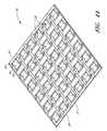
- FIG. 4Ais a perspective view of an embodiment of a panel comprising a plurality of interconnected circuit units.
- FIG. 4Bis a perspective view of the panel of FIG. 4A after having been cut to a desired shape.
- FIG. 5Ais a schematic view of an embodiment of a circuit unit.
- FIG. 5Bis a schematic view of the circuit unit of FIG. 5A with electrical components in place.
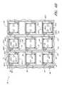
- FIG. 6Ais a schematic view of a plurality of interconnected circuit units.
- FIG. 6Bis a schematic view of an embodiment of a panel containing a plurality of interconnected circuit units with various electrical components attached thereto.
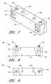
- FIG. 7is a perspective view of an embodiment of a power connector.
- FIG. 8is a front view of the power connector of FIG. 7 .
- FIG. 9is a top view of the power connector of FIG. 7 .
- FIG. 10is a perspective view of the power connector of FIG. 7 attached to a circuit unit of the panel of FIG. 4A .
- FIG. 11is a schematic view of a portion of an embodiment of a panel that has been cut to a desired shape and that contains a plurality of circuit units that are powered by two power connectors.
- a channel illumination apparatus 20comprising a casing 22 in the shape of a “P.”
- the casing 22includes a plurality of side walls 24 and a back 26 , which together define at least one channel 28 .
- the surfaces of the walls 24 and back 26are diffusely-reflective, preferably being coated with a flat white coating.
- the walls 24 and back 26are preferably formed of a durable sturdy metal material.
- a plurality of LED lighting modules 27are mounted to the walls 24 and back 26 of the casing 22 in a spaced-apart manner.
- a translucent light-diffusing cover(not shown) is preferably disposed on a front edge 25 of the walls 24 and encloses the channel 28 .
- Embodiments of channel illumination apparatuses and LED lighting modules for use thereinare described in Applicant's U.S. Pat. No. 6,712,486, issued Mar. 30, 2004, entitled “Mounting Arrangement for Light Emitting Diodes,” and U.S. Pat. No. 6,578,986, issued Jun. 17, 2003, entitled “Modular Mounting Arrangement and Method for Light Emitting Diodes,” both of which are incorporated herein by reference in their entireties and made a part of this specification.
- lamps such as the illustrated LED modules 27may be mounted on the sides 24 and/or back 26 of channel illumination apparatus 20 .
- lamps such as LED modulesare mounted to a panel, such as the back panel of the channel, which has been cut to a desired shape in order to create a shaped lighting effect.
- FIGS. 2 and 3illustrate that a desired shape, such as the letter “P,” may be cut from a panel 30 of material.
- panelis a broad term and is used in its ordinary sense and includes, without limitation, a substrate upon which components such as LEDs may be mounted. In some embodiments, panels are generally flat, thin sheets. It is to be understood, however, that a panel may have any desired shape, size, or contour, including variations in thickness and material, and a panel may be cast, molded, cut, worked, or the like into a desired shape and/or configuration.
- a panelcomprises a sheet of aluminum or other material.
- the panelcomprises a laminate material, such as DIBONDTM, which is available from Alcan.
- a laminate materialcomprises a plastic layer sandwiched between sheets of aluminum.
- the panelis a substrate that comprises a multi-layer panel in which a layer of polyethylene is sandwiched by two layers of aluminum. Panels of this type are available in flat sheets sized four feet by eight feet, although the sheets may be manufactured in various sizes and shapes.
- the cut or otherwise formed panel illustrated in FIG. 3is used as the back 26 of the channel letter of FIG. 1 .
- an illuminated panel 30having light emitting diodes (LEDs) and associated circuitry.
- a sheet 29 of aluminum, or a laminate having a layer of aluminumhas a dielectric layer 31 , such as one or more coats of a diffusely-reflective, nonconductive paint, formed thereon.
- the sheet 29preferably operates as a substrate upon which circuitry may be placed.
- the dielectricpreferably insulates the circuitry from metallic materials of the substrate.
- the paintis preferably diffusely-reflective to distribute light emitted from LEDs placed on the panel 30 .
- a plurality of circuit pathsis disposed on the dielectric layer to form one or more circuit units 32 .
- a plurality of interconnected electrical circuit units 32is disposed on the dielectric layer 31 of the panel 30 .
- Each circuit unit 32is preferably configured to support and power LEDs 62 , 63 , 64 , 65 integrated in the circuit unit 32 so that the panel 30 may be illuminated.
- the panel with the plurality of circuit units 32may be cut to a desired shape and still enable lighting of the LEDs 62 , 63 , 64 , 65 in a plurality of the circuit units 32 .
- a circuit unit 32preferably comprises a positive contact 34 and a negative contact 36 .
- Each circuit unit 32comprises a plurality of circuit paths 33 , 35 electrically communicating between the positive contact 34 and the negative contact 36 .
- the circuit paths 33 , 35comprise a plurality of traces that link electrical components.
- the positive contact 34electrically communicates with the negative contact 36 through a first circuit path 33 and a second circuit path 35 of the circuit unit 32 .
- a first trace 38extends from the positive contact 34 to a first break 40 .
- a second trace 42leads from a location adjacent the first break 40 to a second break 44 .
- a third trace 45leads from a location adjacent the second break 44 to a third break 46 .
- a fourth trace 48extends, in one direction, from the negative contact 36 to a location adjacent the third break 46 .
- the first trace 38extends from the positive contact 34 leads to a fourth break 49 as well as to the first break 40 , as described above.
- a fifth trace 50extends from a location adjacent the fourth break 49 to a fifth break 52 .
- a sixth trace 54extends from a location adjacent the fifth break 52 to a sixth break 56 .
- the fourth trace 48extends from the negative contact 36 to the sixth break 56 in one direction and to the third break 46 in another direction.
- the breaks in the circuit paths 33 , 35preferably are traversed by various electrical components, such as resistors, LEDs, etc.
- the first and second breaks 40 , 44are traversed by a first and second LED 62 , 63 , respectively.
- the fourth and fifth breaks 49 , 52are traversed by a third and fourth LED 64 , 65 , respectively.
- the third and sixth breaks 46 , 56are traversed by a first and second resistor 70 , 72 , respectively.
- the first circuit path 33connects the positive contact 34 and the negative contact 36 through the first trace 38 , the first LED 62 , the second trace 42 , the second LED 63 , the third trace 45 , the first resistor 70 , and the fourth trace 48 .
- the second circuit path 35connects the positive contact 34 and the negative contact 36 through the first trace 38 , the third LED 64 , the fifth trace 50 , the fourth LED 65 , the sixth trace 54 , and the fourth trace 48 .
- the two circuit paths 33 , 35provide a parallel electrical connection between the positive and negative contacts 34 , 36 , each circuit path containing two LEDs and a resistor in series. Also as illustrated, the LEDs and resistors are arranged between the positive and negative contacts so that power is supplied to illuminate the LEDs.
- the illuminated panel 30preferably includes several circuit units 32 that are connected by electrically conductive traces, creating a circuitry pattern 73 .
- FIGS. 6A and 6Bare schematic diagrams illustrating portions of embodiments of an illuminated panel 30 with n identical circuit units 32 ( 1 )- 32 ( n ) (collectively “the circuit units 32 ”).
- the circuit units 32include n positive contacts 34 ( 1 )- 34 ( n ) (collectively “the positive contacts 34 ”) and n negative contacts 36 ( 1 )- 36 ( n ) (collectively “the negative contacts 36 ”).
- circuit units 32Also associated with the circuit units 32 are preferably n first traces 38 ( 1 )- 38 ( n ) (collectively “the first traces 38 ”) and n fourth traces 48 ( 1 )- 48 ( n ) (collectively “the fourth traces 48 ”).
- the circuit unitsare arranged into rows and columns.
- a first connecting trace 74leads from a portion of the first trace 38 ( 1 ) of a circuit unit 32 ( 1 ) to a portion of a first trace 38 ( 2 ) of a second circuit unit 32 ( 2 ). Accordingly, the positive contact 34 ( 1 ) of one circuit unit 32 ( 1 ) is electrically connected to the positive contact 34 ( 2 ) of another circuit unit 32 ( 2 ).
- the circuitry pattern 73preferably includes n first connecting traces 74 ( 1 )- 74 ( n ) (collectively “the first connecting traces 74 ”).
- Several first connecting traces 74in combination electrically connect several positive contacts 34 , forming a common positive source lead 76 .
- the circuitry pattern 73preferably includes a plurality of common positive source leads 76 .
- each row of circuit units 32has a common positive source lead 76 .
- the plurality of common positive source leads 76are interconnected by a plurality of jumpers 86 , as will be described below. As such, the rows of circuit units 32 are all redundantly, electrically, and positively interconnected.
- the circuitry pattern 73also preferably includes a second connecting trace 78 that leads from a portion of the fourth trace 48 ( 1 ) of a first circuit unit 32 ( 1 ) to a portion of a fourth trace 48 ( 2 ) of a second circuit unit 32 ( 2 ). Accordingly, the negative contact 36 ( 1 ) of one circuit unit 32 ( 1 ) is electrically connected to the negative contact 36 ( 2 ) of another circuit unit 32 ( 2 ).
- the circuitry pattern 73also preferably includes n second connecting traces 78 ( 1 )- 78 ( n ) (collectively “the second connecting traces 78 ”).
- the circuitry pattern 73preferably includes a plurality of common negative source leads 80 .
- each row of circuit units 32has a common negative source lead 80 .
- the plurality of common negative source leads 80are also preferably interconnected by a plurality of jumpers 86 . As such, the rows of circuit units 32 are all redundantly, electrically, and negatively connected.
- each first connecting trace 74comprises a first portion 79 and a second portion 81 .
- the first portion 79electrically connects the positive contacts 34 of adjacent circuit units 32 within a row and extends generally in a direction along the row.
- the second portion 81extends generally in a direction transverse to the row and comprises opposing first and second ends 83 , 85 .
- rows of circuit units 32are arranged so that the first and second ends 83 , 85 of first connecting trace 74 second portions 81 of the common positive source leads 76 of adjacent rows are disposed adjacent one another.
- the first and second ends 83 , 85are arranged so that a first connecting trace break 82 electrically separates the common positive source leads 76 of adjacent rows from one another.
- each second connecting trace 78comprises a first portion 95 and a second portion 97 .
- the first portion 95electrically connects the negative contacts 36 of adjacent circuit units 32 within a row and extends generally in a direction along the row.
- the second portion 97extends generally in a direction transverse to the row and comprises opposing first and second ends 91 , 93 .
- rows of circuit units 32are arranged so that the first and second ends 91 , 93 of second connecting trace 78 second portions 97 of the common negative source leads 80 of adjacent rows are disposed adjacent one another.
- the first and second ends 91 , 93are arranged so that a second connecting trace break 84 electrically separates the common negative source leads 80 of adjacent rows from one another.
- the first portion 79 of the first connecting trace 74passes through the second connecting trace break 84 without electrically connecting with the second connecting trace 78 .
- the first portion 95 of the second connecting trace 78passes through the first connecting trace break 82 without electrically connecting with the first connecting trace 74 .
- the breaks 84enable electrical interconnection of the positive contacts 34 of circuit units within a row via the common positive source lead 76 ; and the breaks 82 enable electrical interconnection of the negative contacts 36 of circuit units within a row via the common negative source lead 80 .
- the first connecting trace breaks 82 and the second connecting trace breaks 84preferably are each traversed by a jumper 86 .
- jumpers 86conduct electrical current between the first and second ends 83 , 85 of adjacent first connecting traces 74 and between first and second ends 91 , 93 of the second connecting traces 78 .
- the jumpers 86avoid electrically connecting the first and second connecting traces 74 , 78 to each other. As such, the jumpers 86 electrically interconnect the common positive and negative source leads 76 , 80 of adjacent rows.
- jumperis a broad term and is used herein in its ordinary sense and includes, without limitation, an electrical component that is configured to electrically span a space between two spaced-apart electrical traces or the like so as to electrically interconnect the two traces.
- the jumpers 86interconnect two electrical traces while traversing another trace. Most preferably, a jumper connects traces, but with very little or no resistance.
- the second portions 81 , 97preferably collectively define a plurality of raceways 101 , 103 that extend generally transverse to the common positive and negative source leads 76 , 80 .
- the raceways 101 , 103are configured to interconnect several common positive and negative source leads 76 , 80 and to create redundant leads to the circuit units 32 .
- a circuit unit 32 ( 2 )may receive power from another circuit unit 32 ( 1 ) that is connected to the same common positive and negative lead 76 , 80 , or the circuit unit 32 ( 2 ) may receive power from circuit units 32 located on other common positive and negative leads 76 , 80 through the plurality of raceways 101 , 103 .
- racewayis a broad term and is used herein in its ordinary sense and includes, without limitation, an electrical trace that is configured to interconnect, either by itself or in conjunction with electrical components and other traces, a plurality of common positive or negative source leads 76 , 80 .
- the circuitry pattern 73permits multiple positive traces 76 to be electrically connected to each other, and likewise multiple negative traces 78 are electrically connected to each other.
- the circuitry pattern 73preferably places the circuit units 32 electrically in parallel with one another while also providing redundant electrical supply traces to power each circuit unit 32 . Because of the configuration of this embodiment, the circuitry pattern 73 permits illumination of the LEDs of the circuit units 32 by providing power to any one circuit unit 32 within the electrically connected circuitry pattern 73 .
- the electrical connection between circuit units 32is redundant, and circuit units 32 will remain electrically connected even if one or more connective traces are removed, interrupted, or one or more of the electrical components, such as a jumper, fails.
- the circuitry pattern 73is printed on the dielectric surface and comprises an electrically conductive material such as silver ink.
- an electrically conductive materialsuch as silver ink.
- conventional printing technologiessuch as offset printing or inkjet printing, are used to apply silver ink or another printable conductive material. It is to be understood that other methods, including electrochemical etching, may be used to form the conductive traces of the circuitry 73 .
- the electrical componentssuch as LEDs, resistors, and jumpers are shown disposed on the printed circuitry pattern 73 . As shown, such electrical components are electrically connected to the conductive traces so that current flows therethrough. Thus, due to the electrical interconnections and redundant electrical paths, an entire or partial panel comprising such circuit units 32 may be powered and illuminated by applying power to one circuit unit 32 .
- the electrical componentsare attached using a conductive silver epoxy. Of course, other methods and materials, such as soldering, may be used to connect the electrical components in place.
- a power connector 88is shown for supplying power across the positive and negative contacts 34 , 36 of a circuit unit 32 .
- the illustrated power connector 88comprises an elongate body 87 and preferably comprises a pair of wire holders 90 .
- Each wire holder 90comprises a first hole 92 to receive a wire or other conductor and a second hole 94 to receive a bolt or screw 96 (shown in FIG. 8 ).
- the second hole 94is preferably configured to permit placement of the bolt or screw 96 therein to engage and tightly hold the wire therein. It is to be understood that other embodiments can employ another arrangement to engage a conductor for supplying power to the connector 88 .
- Each wire holder 90is electrically connected to a respective power connector contact 98 , 99 , shown in FIG. 8 . More specifically, a wire holder 90 may be configured to electrically connect a positive supply wire to a first power connector contact 98 , and the other wire holder 90 may be configured to electrically connect a negative supply wire to a second power connector contact 99 .
- the power connector contacts 98 , 99are electrically insulated from one another.
- the power connector contacts 98 , 99preferably are spaced apart a distance that corresponds to the distance between the positive and negative contacts 34 , 36 .
- the power connector 88may be arranged to fit onto the panel 30 so that the first and second power connector contacts 98 , 99 engage corresponding positive and negative contacts 34 , 36 of a circuit unit 32 . As such, power is supplied by the power connector 88 to the circuit unit 32 .
- the power connector 88further preferably comprises a pair of connector screw holes 100 formed therethrough for securing the power connector 88 to the panel 30 .
- the power connector 88preferably is secured with a screw or bolt.
- the power connector 88can be secured by a length of adhesive, most preferably double-stick tape, which is disposed on a bottom surface of the power connector 88 . As such, the power connector contacts 98 , 99 and the positive and negative contacts 34 , 36 are engaged, and the power connector 88 can be secured in place.
- the panel 30preferably provides at least a visual indicator 89 (shown in FIG. 5A ) corresponding to the connector 88 to ensure that the connector 88 is applied correctly.
- the visual indicator 89may comprise a marking on the panel 30 that is shaped in a right angle.
- the right angle markingcorresponds to a corner or edge of the connector 88 . Accordingly, when the connector 88 is placed on the panel 30 to connect the positive and negative contacts 34 , 36 , the visual indicator 89 may align the edges of the connector 88 to confirm that the connector 88 is properly positioned.
- the positive and negative contacts 34 , 36are preferably marked with a “+” for the positive contact 34 and a “ ⁇ ” for the negative contact 36 .
- the power connector 88preferably is quickly and easily secured in place by applying the adhesive to the panel 30 so that the adhesive holds the power connector 88 in place with the positive and negative contacts correctly aligned.
- self tapping screwspreferably are advanced through the connector screw holes 100 and into the panel 30 . As such, the power connector 88 is securely attached to the panel 30 in a manner so that power is appropriately applied to the circuit unit 32 .
- an illuminated panelcomprising a circuit unit pattern disposed on substantially the entire panel.
- the panelis provided in a standard rectangular sheet, such as a 4′ ⁇ 8′ sheet, as shown in FIG. 4A .
- the panelmay be provided pre-shaped in a variety of standard shapes, and the circuit units 32 may be arranged so that one power connector 88 provides power to all or most of the circuit units 32 .
- FIGS. 4A-Bit is anticipated that an illuminated panel is cut or shaped to a custom or desired shape, as in FIGS. 4A-B .
- such cuttingmay disrupt circuit units 32 and the electrical connecting traces therebetween so that the circuit units 32 on the panel 30 are not necessarily all electrically connected to one another.
- groups of circuit units 32are still electrically connected.
- FIG. 11shows a portion of an embodiment of a panel that has been cut to a desired shape. In the illustrated embodiment, a first group of circuit units G 1 is electrically connected to one another, but a second group G 2 of circuit units G 2 is electrically isolated from the first group G 1 . However, circuit units in the second group G 2 are electrically connected to one another.
- the panel 30is illuminated by applying a first power connector 88 ( 1 ) to one of the circuit units 32 of the first group G 1 and applying a second power connector 88 ( 2 ) to one of the circuit units 32 of the second group G 2 .
- a first power connector 88 ( 1 )to one of the circuit units 32 of the first group G 1
- a second power connector 88 ( 2 )to one of the circuit units 32 of the second group G 2 .
- identification of groups that require separate power connectors 88may be made by connecting power connectors 88 to the panel 30 .
- a power connector 88is connected to the panel 30 , and the panel 30 is illuminated. If some circuit units 32 are electrically disconnected from the illuminated circuit units 32 , the disconnected circuit units 32 will not be illuminated. Another power connector 88 is thus applied to one or more of the dark, or disconnected, circuit units 32 . Application of another power connector 88 will likely illuminate one or more circuit units 32 , but it may not illuminate all desired circuit units 32 . If there remain disconnected circuit units 32 that are not illuminated, power connectors may be applied to them until an adequate or desired number of circuit units 32 are illuminated.
- the panelmay be configured such that each power connector 88 supplies electrical power to at least two circuit units.
- the panelincludes an overall ratio of at least two illuminatable circuit units per power connector.
- the principles discussed hereinmay be applied to panels comprising other materials and configured for other applications.
- the panelcan comprise one or more of several types of materials, can be relatively rigid, relatively flexible, or can comprise portions of varied rigidity, while still employing the principles discussed herein.
- the panelmay function as a dielectric with or without the need for any coating or applied layer.
- the panelcomprises a laminate material comprising rigid outer lamina separated by a light-weight inner layer, such as honeycomb material.
- a light-weight inner layersuch as honeycomb material.
- Such an inner layermay be constructed of any desired material, such as polyethylene, Kevlar, or the like.
- the outer layermay comprise a metal, ceramic, hard plastic, foam, or the like.
- the panelcomprises a layer of polyethylene, or some other polymer, that is sandwiched by two layers of aluminum.
- the panelis cut to a desired shape by a router or other cutting means.
- the polyethyleneprovides a proper lubricant for the cutting tools so that cutting tools need no additional lubrication during cutting. This may reduce or eliminate the lubricating oil typically used during the metal sheet cutting process, which may save the manufacturer the cost of the oil and the time required to clean the panel following cutting.
- circuit units 32could have a single LED per path, coupled with one resistor.
- the circuit units 32could have several LEDs per path with no resistors, or no resistors may be necessary.
- materials with differing resistivitymay be used for at least some of the traces in the circuit units 32 , obviating the need for the resistors.
- different color LEDsmay be used in the same or different circuit units 32 . Additionally, LEDs of different sizes may also be used.
- additional circuitry and componentssuch as light sensors, may be included on an embodiment of a lighted panel.
- at least one circuit unit on the panelis redundantly powered like other circuit units on the panel, but comprises a light sensor rather than LEDs.
- the sensor circuit unitis thus configured differently than the LED circuit units.
- a first set of circuit units 32may contain LEDs of a first color
- a second set of circuit units 32may contain LEDs of a second color.
- the first set of circuit units 32is not electrically connected to the second set of circuit units 32 . In this arrangement, providing power to the first set of circuit units 32 will provide illumination in the first color, and providing power to the second set of circuit units 32 will provide illumination in the second color.
- a color-changing illumination apparatusmay be provided.
- the circuitry pattern 73may be configured to permit placement of the electrical components in the same orientation.
- the jumpers, resistors, and even LEDshave an elongate shape that includes a longitudinal axis between positive and negative contacts.
- the circuitry pattern 73may be configured to permit parallel and/or coaxial orientation of the electrical components.
- the parallel orientation of the electrical componentsmay facilitate the assembly process, which may involve a device that is configured to pick up the components from a supply area and place the components in a specified location and orientation on the panel.
- the orientations of the electrical componentsmay be different than that shown in the figures.
- the LEDsare shown to be spaced generally equidistant from other LEDs in the circuit unit 32 and from LEDs in other circuit units 32 . This may facilitate manufacturing and assembly of the illuminated panel 30 . This may also provide uniformity of light output when the LEDs are illuminated. In another embodiment, the LEDs may vary in relative location with other LEDs. In the illustrated embodiment, the circuit units and LEDs are arranged so that adjacent LEDs are positioned about one inch apart, while in other embodiments, the LEDs may be placed uniformly or non-uniformly between about one-half inch to about 5 inches apart. In yet other embodiments, the LEDs may be placed uniformly or non-uniformly significantly less than about one-half an inch or significantly more than about 5 inches.
- the electrical componentsare attached using a conductive epoxy.
- the illuminated panelmay then be heated to an elevated temperature to cure the epoxy.
- the illuminated panelemploys an epoxy that may be cured at about 150° F. (e.g., silver epoxy).
- the illuminated panelmay be cured at temperatures ranging from about 120° F. to about 200° F.
- the illuminated panelmay be cured at temperatures less than about 120° F. or greater than about 200° F.
- the illuminated panelmay be cured at room temperature (about 25 C).
- Conductive epoxy having a relatively low curing temperatureis especially useful in embodiments wherein the panel comprises a material, such as certain foams, that may melt or otherwise degrade at relatively low temperatures.
- conductive epoxy having a relatively low curing temperatureis used when the panel comprises a foam that begins to melt or degrade at about 140° F.
- the panel 30may be made from various materials and may assume varying shapes.
- the panel 30may be made from laminates.
- the panel 30may be made from sheets of aluminum, foam, non-laminates, hard plastics, any combination of such materials, or other materials that would be suitable for the purposes of the illuminated panel 30 .
- the panel 30may originate in a rectangular form.
- the panel 30may be manufactured in other forms or shapes.
- the panel 30may be manufactured in shapes that are substantially circular, square, oval, pentagonal, hexagonal, etc.
- the panel 30may also have surface contours.
- the surface contour of the panel 30may be cylindrical, parabolic, irregular, etc.
- the circuit units 32may also be configured differently than in the illustrated embodiment.
- the circuit units 32could be circular, elliptical, or other shapes that may still accommodate the function of the circuit units 32 .
- the circuitry pattern 73may contain circuit units 32 of the same shape and size, as illustrated in the figures, or the circuitry pattern 73 may include circuit units 32 of varying shapes and size. In yet other embodiments, it is contemplated that at least one, or even substantially all, of the circuit units 32 may be irregular in shape or size with respect to other circuit units 32 .
- the connecting traces 74 , 78may also vary from that shown in the figures.
- the connecting traces 74 , 78may include more or less redundant connections between circuit units 32 .
- the circuit units 32may be configured with two or more circuit units 32 in series between parallel connections.
- the circuit units 32may be configured such that not every circuit unit 32 contains a positive and negative contact 34 , 36 , or the contacts 34 , 36 are arranged between circuit units 32 . Still further embodiments may arrange circuit units in a manner different than the illustrated row/column arrangement.
- a panel as discussed abovemay be mounted on the underside of a shelf or other surface, and the LEDs may illuminate the space below the shelf.
- the panelcomprises a rigid laminate layer that functions as a shelf, and the circuit units and LEDs provide illumination beneath or, in another embodiment, above, the shelf.
- white LEDsare disposed on the panel, and the panel is shaped to comprise an overhead lighting fixture for offices or the like.
- a panelis disposed in a refrigerator to light the refrigerator.
- a panelcomprises a laminate structure wherein a first outer layer comprises circuit units and LEDs, and an opposite, second outer layer comprises a decorative fascia.
- a panel 30is employed as a halo light.
- a halo lightmay be created around the decorative fascia by illuminating the panel 30 and placing the panel 30 adjacent but spaced from a wall so that the light from the panel 30 illuminates the wall. This arrangement will create a halo effect around the decorative fascia when viewed from the non-illuminated side of the panel 30 .
- the panelcomprises a foam sheet.
- the foam sheetpreferably comprises a plurality of circuit units on one side.
- the foam sheetis cut to a desired shape, and graphics or designs may be applied to the side of the foam sheet opposite the side on which the circuit units are located.
- the foam sheetmay be illuminated by providing power to the circuit units, and the sheet may be positioned adjacent a wall so that the light from the sheet illuminates the wall to create a halo effect around the graphics or design when viewed from the non-illuminated side of the sheet.
- the graphics or designsmay be applied to the foam sheet before the sheet is cut to the desired shape.
- electrical componentsare attached to traces by a material that can be deposited at relatively low temperatures, such as, for example, a silver epoxy configured to be curable at a temperature less than about 150° F.
- a back of the channel letterpreferably is provided.
- the backpreferably comprises an illuminated panel.
- the methodfurther comprises forming the back to a desired shape, providing sides corresponding to the back shape, and providing electrical power to the circuit unit.
- Other methods and apparatus discussed hereincan also be employed, as appropriate, when making a channel letter.
Landscapes
- Engineering & Computer Science (AREA)
- Theoretical Computer Science (AREA)
- Physics & Mathematics (AREA)
- General Physics & Mathematics (AREA)
- Power Engineering (AREA)
- Human Computer Interaction (AREA)
- General Engineering & Computer Science (AREA)
- Arrangement Of Elements, Cooling, Sealing, Or The Like Of Lighting Devices (AREA)
- Non-Portable Lighting Devices Or Systems Thereof (AREA)
Abstract
Description
Claims (13)
Priority Applications (2)
| Application Number | Priority Date | Filing Date | Title |
|---|---|---|---|
| US11/014,651US8188503B2 (en) | 2004-05-10 | 2004-12-16 | Cuttable illuminated panel |
| US13/482,909US20120300461A1 (en) | 2004-05-10 | 2012-05-29 | Cuttable illuminated panel |
Applications Claiming Priority (2)
| Application Number | Priority Date | Filing Date | Title |
|---|---|---|---|
| US56981404P | 2004-05-10 | 2004-05-10 | |
| US11/014,651US8188503B2 (en) | 2004-05-10 | 2004-12-16 | Cuttable illuminated panel |
Related Child Applications (1)
| Application Number | Title | Priority Date | Filing Date |
|---|---|---|---|
| US13/482,909ContinuationUS20120300461A1 (en) | 2004-05-10 | 2012-05-29 | Cuttable illuminated panel |
Publications (2)
| Publication Number | Publication Date |
|---|---|
| US20050251698A1 US20050251698A1 (en) | 2005-11-10 |
| US8188503B2true US8188503B2 (en) | 2012-05-29 |
Family
ID=35240733
Family Applications (2)
| Application Number | Title | Priority Date | Filing Date |
|---|---|---|---|
| US11/014,651Expired - Fee RelatedUS8188503B2 (en) | 2004-05-10 | 2004-12-16 | Cuttable illuminated panel |
| US13/482,909AbandonedUS20120300461A1 (en) | 2004-05-10 | 2012-05-29 | Cuttable illuminated panel |
Family Applications After (1)
| Application Number | Title | Priority Date | Filing Date |
|---|---|---|---|
| US13/482,909AbandonedUS20120300461A1 (en) | 2004-05-10 | 2012-05-29 | Cuttable illuminated panel |
Country Status (1)
| Country | Link |
|---|---|
| US (2) | US8188503B2 (en) |
Cited By (5)
| Publication number | Priority date | Publication date | Assignee | Title |
|---|---|---|---|---|
| US9288911B2 (en)* | 2010-03-16 | 2016-03-15 | At&S Austria Technologie & Systemtechnik Aktiengesellschaft | Method and composite assembly for processing or treating a plurality of printed circuit boards and use therefor |
| US20160273732A1 (en)* | 2015-03-18 | 2016-09-22 | Lite-On Technology Corporation | Indicating device |
| US9927102B2 (en)* | 2012-09-06 | 2018-03-27 | Cooledge Lighting, Inc. | Sealed and sealable lighting systems incorporating flexible light sheets and related methods |
| US10707635B2 (en) | 2017-05-15 | 2020-07-07 | Current Lighting Solutions, Llc | Method for providing a wire connection to a printed circuit board |
| USD936145S1 (en)* | 2019-07-26 | 2021-11-16 | My Gift Enterprise, LLC | Block sign |
Families Citing this family (48)
| Publication number | Priority date | Publication date | Assignee | Title |
|---|---|---|---|---|
| US7564180B2 (en) | 2005-01-10 | 2009-07-21 | Cree, Inc. | Light emission device and method utilizing multiple emitters and multiple phosphors |
| US8125137B2 (en)* | 2005-01-10 | 2012-02-28 | Cree, Inc. | Multi-chip light emitting device lamps for providing high-CRI warm white light and light fixtures including the same |
| US7525248B1 (en) | 2005-01-26 | 2009-04-28 | Ac Led Lighting, L.L.C. | Light emitting diode lamp |
| US8272757B1 (en)* | 2005-06-03 | 2012-09-25 | Ac Led Lighting, L.L.C. | Light emitting diode lamp capable of high AC/DC voltage operation |
| US7872430B2 (en) | 2005-11-18 | 2011-01-18 | Cree, Inc. | Solid state lighting panels with variable voltage boost current sources |
| EP1963740A4 (en) | 2005-12-21 | 2009-04-29 | Cree Led Lighting Solutions | Lighting device and lighting method |
| WO2007075742A2 (en) | 2005-12-21 | 2007-07-05 | Cree Led Lighting Solutions, Inc. | Lighting device |
| CN101351891B (en) | 2005-12-22 | 2014-11-19 | 科锐公司 | lighting device |
| US7852009B2 (en)* | 2006-01-25 | 2010-12-14 | Cree, Inc. | Lighting device circuit with series-connected solid state light emitters and current regulator |
| US9084328B2 (en) | 2006-12-01 | 2015-07-14 | Cree, Inc. | Lighting device and lighting method |
| US8513875B2 (en) | 2006-04-18 | 2013-08-20 | Cree, Inc. | Lighting device and lighting method |
| US7828460B2 (en) | 2006-04-18 | 2010-11-09 | Cree, Inc. | Lighting device and lighting method |
| WO2007124036A2 (en) | 2006-04-20 | 2007-11-01 | Cree Led Lighting Solutions, Inc. | Lighting device and lighting method |
| US7648257B2 (en) | 2006-04-21 | 2010-01-19 | Cree, Inc. | Light emitting diode packages |
| US7625103B2 (en)* | 2006-04-21 | 2009-12-01 | Cree, Inc. | Multiple thermal path packaging for solid state light emitting apparatus and associated assembling methods |
| WO2007142946A2 (en) | 2006-05-31 | 2007-12-13 | Cree Led Lighting Solutions, Inc. | Lighting device and method of lighting |
| US7714348B2 (en)* | 2006-10-06 | 2010-05-11 | Ac-Led Lighting, L.L.C. | AC/DC light emitting diodes with integrated protection mechanism |
| US8029155B2 (en) | 2006-11-07 | 2011-10-04 | Cree, Inc. | Lighting device and lighting method |
| KR101408613B1 (en)* | 2006-11-30 | 2014-06-20 | 크리, 인코포레이티드 | Self-ballasted solid state lighting devices |
| US9441793B2 (en) | 2006-12-01 | 2016-09-13 | Cree, Inc. | High efficiency lighting device including one or more solid state light emitters, and method of lighting |
| US7918581B2 (en) | 2006-12-07 | 2011-04-05 | Cree, Inc. | Lighting device and lighting method |
| TWI560405B (en) | 2007-02-22 | 2016-12-01 | Cree Inc | Lighting devices, methods of lighting, light filters and methods of filtering light |
| JP2010527510A (en) | 2007-05-08 | 2010-08-12 | クリー エル イー ディー ライティング ソリューションズ インコーポレイテッド | Lighting device and lighting method |
| US7744243B2 (en) | 2007-05-08 | 2010-06-29 | Cree Led Lighting Solutions, Inc. | Lighting device and lighting method |
| KR20100022969A (en) | 2007-05-08 | 2010-03-03 | 크리 엘이디 라이팅 솔루션즈, 인크. | Lighting device and lighting method |
| EP2156090B1 (en) | 2007-05-08 | 2016-07-06 | Cree, Inc. | Lighting device and lighting method |
| US10030824B2 (en) | 2007-05-08 | 2018-07-24 | Cree, Inc. | Lighting device and lighting method |
| US7863635B2 (en) | 2007-08-07 | 2011-01-04 | Cree, Inc. | Semiconductor light emitting devices with applied wavelength conversion materials |
| JP2011501417A (en) | 2007-10-10 | 2011-01-06 | クリー エル イー ディー ライティング ソリューションズ インコーポレイテッド | Lighting device and manufacturing method |
| WO2009098323A2 (en)* | 2008-02-08 | 2009-08-13 | G-Lec Europe Gmbh | Display device and securing means |
| RU2499331C2 (en)* | 2008-06-17 | 2013-11-20 | Конинклейке Филипс Электроникс Н.В. | Alternating current driven light-emitting device |
| US8240875B2 (en) | 2008-06-25 | 2012-08-14 | Cree, Inc. | Solid state linear array modules for general illumination |
| US8921876B2 (en) | 2009-06-02 | 2014-12-30 | Cree, Inc. | Lighting devices with discrete lumiphor-bearing regions within or on a surface of remote elements |
| CN102630288B (en) | 2009-09-25 | 2015-09-09 | 科锐公司 | Lighting fixtures with low glare and high brightness level uniformity |
| US7893445B2 (en)* | 2009-11-09 | 2011-02-22 | Cree, Inc. | Solid state emitter package including red and blue emitters |
| DE102010000758A1 (en)* | 2010-01-11 | 2011-07-14 | Robert Bosch GmbH, 70469 | Method for manufacturing LED module with multiple LEDs in e.g. automotive engineering taillight, involves cutting freely thin sheet arrangement of carrier film along one outer contour of thin sheet arrangement in order to obtain LED module |
| US9275979B2 (en) | 2010-03-03 | 2016-03-01 | Cree, Inc. | Enhanced color rendering index emitter through phosphor separation |
| US11251164B2 (en) | 2011-02-16 | 2022-02-15 | Creeled, Inc. | Multi-layer conversion material for down conversion in solid state lighting |
| US10946792B2 (en)* | 2011-03-04 | 2021-03-16 | Michael Shipman | Illuminated vehicular assembly for day and night use |
| ITMI20110775A1 (en)* | 2011-05-06 | 2012-11-07 | Insigna Industry S R L | LIGHTED SIGN |
| JP6419089B2 (en)* | 2013-02-28 | 2018-11-07 | フィリップス ライティング ホールディング ビー ヴィ | Simple LED package suitable for capacitive drive |
| USD750317S1 (en) | 2013-03-15 | 2016-02-23 | Cree, Inc. | Bay lighting fixture |
| US10788177B2 (en) | 2013-03-15 | 2020-09-29 | Ideal Industries Lighting Llc | Lighting fixture with reflector and template PCB |
| US10436432B2 (en)* | 2013-03-15 | 2019-10-08 | Cree, Inc. | Aluminum high bay light fixture having plurality of housings dissipating heat from light emitting elements |
| US10527273B2 (en) | 2013-03-15 | 2020-01-07 | Ideal Industries Lighting, LLC | Lighting fixture with branching heat sink and thermal path separation |
| CN104241262B (en) | 2013-06-14 | 2020-11-06 | 惠州科锐半导体照明有限公司 | Light emitting device and display device |
| DE102017105722A1 (en)* | 2017-03-16 | 2018-09-20 | Siteco Beleuchtungstechnik Gmbh | LED luminaire module with flat carrier for LEDs |
| US11460173B1 (en) | 2021-01-05 | 2022-10-04 | BrooksCo, LLC | LED backlight system and mounting system |
Citations (60)
| Publication number | Priority date | Publication date | Assignee | Title |
|---|---|---|---|---|
| US4173035A (en) | 1977-12-01 | 1979-10-30 | Media Masters, Inc. | Tape strip for effecting moving light display |
| US4854062A (en)* | 1988-01-25 | 1989-08-08 | Bayo Luis E | Illuminated house number device |
| US4907361A (en) | 1987-02-18 | 1990-03-13 | Villard Jean Pierre | Luminous panel for advertising on the ground |
| US5020253A (en)* | 1990-02-06 | 1991-06-04 | Lie Liat Chaw | Display board assembly |
| US5107408A (en) | 1988-03-31 | 1992-04-21 | Consumerville Limited | Lighting system |
| US5278432A (en) | 1992-08-27 | 1994-01-11 | Quantam Devices, Inc. | Apparatus for providing radiant energy |
| US5296310A (en) | 1992-02-14 | 1994-03-22 | Materials Science Corporation | High conductivity hydrid material for thermal management |
| US5321593A (en) | 1992-10-27 | 1994-06-14 | Moates Martin G | Strip lighting system using light emitting diodes |
| EP0632511A2 (en) | 1993-06-29 | 1995-01-04 | MITSUBISHI CABLE INDUSTRIES, Ltd. | A light emitting diode aggregate module and a method for manufacturing a light emitting diode aggregate module |
| US5490788A (en) | 1994-11-01 | 1996-02-13 | Emc Technology, Inc. | Surface mount terminal for electrical component |
| US5581876A (en) | 1995-01-27 | 1996-12-10 | David Sarnoff Research Center, Inc. | Method of adhering green tape to a metal support substrate with a bonding glass |
| US5660461A (en) | 1994-12-08 | 1997-08-26 | Quantum Devices, Inc. | Arrays of optoelectronic devices and method of making same |
| WO1997037385A1 (en) | 1996-04-03 | 1997-10-09 | Pressco Technology, Inc. | High-density solid-state lighting array for machine vision applications |
| US5772208A (en)* | 1995-11-07 | 1998-06-30 | Mctaggart; Stephen I. | Game board incorporating apparatus for selectively providing sensory game enhancement and method for making the same |
| US5857767A (en) | 1996-09-23 | 1999-01-12 | Relume Corporation | Thermal management system for L.E.D. arrays |
| EP0921568A2 (en) | 1997-11-25 | 1999-06-09 | Matsushita Electric Works, Ltd. | LED Luminaire |
| US5927845A (en) | 1995-08-28 | 1999-07-27 | Stantech | Integrally formed linear light strip with light emitting diodes |
| US6042248A (en) | 1997-10-15 | 2000-03-28 | Lektron Industrial Supply, Inc. | LED assembly for illuminated signs |
| US6045240A (en) | 1996-06-27 | 2000-04-04 | Relume Corporation | LED lamp assembly with means to conduct heat away from the LEDS |
| US6131651A (en) | 1998-09-16 | 2000-10-17 | Advanced Ceramics Corporation | Flexible heat transfer device and method |
| US6249267B1 (en) | 1996-02-19 | 2001-06-19 | Rohm Co., Ltd | Display apparatus having heat dissipation |
| US6250774B1 (en) | 1997-01-23 | 2001-06-26 | U.S. Philips Corp. | Luminaire |
| US6299337B1 (en) | 1999-03-04 | 2001-10-09 | Osram Opto Semiconductors Gmbh & Co. Ohg | Flexible multiple led module, in particular for a luminaire housing of a motor vehicle |
| US6367949B1 (en) | 1999-08-04 | 2002-04-09 | 911 Emergency Products, Inc. | Par 36 LED utility lamp |
| US6371637B1 (en) | 1999-02-26 | 2002-04-16 | Radiantz, Inc. | Compact, flexible, LED array |
| US6428189B1 (en) | 2000-03-31 | 2002-08-06 | Relume Corporation | L.E.D. thermal management |
| US6517218B2 (en) | 2000-03-31 | 2003-02-11 | Relume Corporation | LED integrated heat sink |
| US6528954B1 (en) | 1997-08-26 | 2003-03-04 | Color Kinetics Incorporated | Smart light bulb |
| US6573536B1 (en) | 2002-05-29 | 2003-06-03 | Optolum, Inc. | Light emitting diode light source |
| US6578986B2 (en) | 2001-06-29 | 2003-06-17 | Permlight Products, Inc. | Modular mounting arrangement and method for light emitting diodes |
| US20030112627A1 (en) | 2000-09-28 | 2003-06-19 | Deese Raymond E. | Flexible sign illumination apparatus, system and method |
| US6582100B1 (en) | 2000-08-09 | 2003-06-24 | Relume Corporation | LED mounting system |
| US20030174517A1 (en) | 2002-03-18 | 2003-09-18 | Chris Kiraly | Extensible linear light emitting diode illumination source |
| US20030189830A1 (en) | 2001-04-12 | 2003-10-09 | Masaru Sugimoto | Light source device using led, and method of producing same |
| US20030218417A1 (en) | 2002-05-22 | 2003-11-27 | Unity Opto Technology Co., Ltd. | Light emitting diode lamp with light emitting diode module having improved heat dissipation |
| US20030223235A1 (en) | 2002-06-03 | 2003-12-04 | Ferenc Mohacsi | LED accent lighting units |
| US20030230934A1 (en) | 2002-06-17 | 2003-12-18 | Cordelli Gary Gerard | Modular power supply with multiple and interchangeable output units for AC- and DC-powered equipment |
| US6712486B1 (en) | 1999-10-19 | 2004-03-30 | Permlight Products, Inc. | Mounting arrangement for light emitting diodes |
| US20040066142A1 (en) | 2002-10-03 | 2004-04-08 | Gelcore, Llc | LED-based modular lamp |
| US20040150954A1 (en) | 2003-01-31 | 2004-08-05 | Belady Christian L. | Power module for multi-chip printed circuit boards |
| US20040188593A1 (en) | 2003-03-20 | 2004-09-30 | Patrick Mullins | Photosensor control unit |
| US20040233671A1 (en) | 2001-09-13 | 2004-11-25 | Gerhard Staufert | Led-luminous panel and carrier plate |
| US6930332B2 (en) | 2001-08-28 | 2005-08-16 | Matsushita Electric Works, Ltd. | Light emitting device using LED |
| US20060006405A1 (en) | 2003-05-05 | 2006-01-12 | Lamina Ceramics, Inc. | Surface mountable light emitting diode assemblies packaged for high temperature operation |
| US20060098440A1 (en) | 2004-11-05 | 2006-05-11 | David Allen | Solid state lighting device with improved thermal management, improved power management, adjustable intensity, and interchangable lenses |
| US7081645B2 (en) | 2004-10-08 | 2006-07-25 | Bright Led Electronics Corp. | SMD(surface mount device)-type light emitting diode with high heat dissipation efficiency and high power |
| US7102172B2 (en) | 2003-10-09 | 2006-09-05 | Permlight Products, Inc. | LED luminaire |
| US20060221609A1 (en) | 2003-06-12 | 2006-10-05 | Ryan Patrick H Jr | Lighting strip |
| US20070007558A1 (en) | 2005-06-27 | 2007-01-11 | Mazzochette Joseph B | Light emitting diode package and method for making same |
| US20070018311A1 (en) | 2005-07-08 | 2007-01-25 | Hon Hai Precision Industry Co., Ltd. | Circuit board and light souce device having same |
| US7176502B2 (en) | 2003-05-05 | 2007-02-13 | Lamina Ceramics, Inc. | Light emitting diodes packaged for high temperature operation |
| US20070041220A1 (en) | 2005-05-13 | 2007-02-22 | Manuel Lynch | LED-based luminaire |
| US7183640B2 (en) | 1999-12-13 | 2007-02-27 | Lamina Ceramics, Inc. | Method and structures for enhanced temperature control of high power components on multilayer LTCC and LTCC-M boards |
| US7213940B1 (en) | 2005-12-21 | 2007-05-08 | Led Lighting Fixtures, Inc. | Lighting device and lighting method |
| US7252408B2 (en) | 2004-07-19 | 2007-08-07 | Lamina Ceramics, Inc. | LED array package with internal feedback and control |
| US7315049B2 (en) | 2004-05-18 | 2008-01-01 | Onscreen Technologies, Inc. | LED assembly with vented circuit board |
| US7329024B2 (en) | 2003-09-22 | 2008-02-12 | Permlight Products, Inc. | Lighting apparatus |
| US20080079349A1 (en)* | 1999-03-05 | 2008-04-03 | Canon Kabushiki Kaisha | Image formation apparatus |
| US20080192462A1 (en) | 2007-02-14 | 2008-08-14 | James Steedly | Strip illumination device |
| US7497596B2 (en) | 2001-12-29 | 2009-03-03 | Mane Lou | LED and LED lamp |
- 2004
- 2004-12-16USUS11/014,651patent/US8188503B2/ennot_activeExpired - Fee Related
- 2012
- 2012-05-29USUS13/482,909patent/US20120300461A1/ennot_activeAbandoned
Patent Citations (68)
| Publication number | Priority date | Publication date | Assignee | Title |
|---|---|---|---|---|
| US4173035A (en) | 1977-12-01 | 1979-10-30 | Media Masters, Inc. | Tape strip for effecting moving light display |
| US4907361A (en) | 1987-02-18 | 1990-03-13 | Villard Jean Pierre | Luminous panel for advertising on the ground |
| US4854062A (en)* | 1988-01-25 | 1989-08-08 | Bayo Luis E | Illuminated house number device |
| US5107408A (en) | 1988-03-31 | 1992-04-21 | Consumerville Limited | Lighting system |
| US5020253A (en)* | 1990-02-06 | 1991-06-04 | Lie Liat Chaw | Display board assembly |
| US5296310A (en) | 1992-02-14 | 1994-03-22 | Materials Science Corporation | High conductivity hydrid material for thermal management |
| US5278432A (en) | 1992-08-27 | 1994-01-11 | Quantam Devices, Inc. | Apparatus for providing radiant energy |
| US5321593A (en) | 1992-10-27 | 1994-06-14 | Moates Martin G | Strip lighting system using light emitting diodes |
| EP0632511A2 (en) | 1993-06-29 | 1995-01-04 | MITSUBISHI CABLE INDUSTRIES, Ltd. | A light emitting diode aggregate module and a method for manufacturing a light emitting diode aggregate module |
| US5490788A (en) | 1994-11-01 | 1996-02-13 | Emc Technology, Inc. | Surface mount terminal for electrical component |
| US5660461A (en) | 1994-12-08 | 1997-08-26 | Quantum Devices, Inc. | Arrays of optoelectronic devices and method of making same |
| US5581876A (en) | 1995-01-27 | 1996-12-10 | David Sarnoff Research Center, Inc. | Method of adhering green tape to a metal support substrate with a bonding glass |
| US5927845A (en) | 1995-08-28 | 1999-07-27 | Stantech | Integrally formed linear light strip with light emitting diodes |
| US5772208A (en)* | 1995-11-07 | 1998-06-30 | Mctaggart; Stephen I. | Game board incorporating apparatus for selectively providing sensory game enhancement and method for making the same |
| US6249267B1 (en) | 1996-02-19 | 2001-06-19 | Rohm Co., Ltd | Display apparatus having heat dissipation |
| WO1997037385A1 (en) | 1996-04-03 | 1997-10-09 | Pressco Technology, Inc. | High-density solid-state lighting array for machine vision applications |
| US6045240A (en) | 1996-06-27 | 2000-04-04 | Relume Corporation | LED lamp assembly with means to conduct heat away from the LEDS |
| US5857767A (en) | 1996-09-23 | 1999-01-12 | Relume Corporation | Thermal management system for L.E.D. arrays |
| US6250774B1 (en) | 1997-01-23 | 2001-06-26 | U.S. Philips Corp. | Luminaire |
| US6528954B1 (en) | 1997-08-26 | 2003-03-04 | Color Kinetics Incorporated | Smart light bulb |
| US6042248A (en) | 1997-10-15 | 2000-03-28 | Lektron Industrial Supply, Inc. | LED assembly for illuminated signs |
| EP0921568A2 (en) | 1997-11-25 | 1999-06-09 | Matsushita Electric Works, Ltd. | LED Luminaire |
| US6131651A (en) | 1998-09-16 | 2000-10-17 | Advanced Ceramics Corporation | Flexible heat transfer device and method |
| US6371637B1 (en) | 1999-02-26 | 2002-04-16 | Radiantz, Inc. | Compact, flexible, LED array |
| US6299337B1 (en) | 1999-03-04 | 2001-10-09 | Osram Opto Semiconductors Gmbh & Co. Ohg | Flexible multiple led module, in particular for a luminaire housing of a motor vehicle |
| US20080079349A1 (en)* | 1999-03-05 | 2008-04-03 | Canon Kabushiki Kaisha | Image formation apparatus |
| US6367949B1 (en) | 1999-08-04 | 2002-04-09 | 911 Emergency Products, Inc. | Par 36 LED utility lamp |
| US7114831B2 (en) | 1999-10-19 | 2006-10-03 | Permlight Products, Inc. | Mounting arrangement for light emitting diodes |
| US7306353B2 (en) | 1999-10-19 | 2007-12-11 | Permlight Products, Inc. | Mounting arrangement for light emitting diodes |
| US6712486B1 (en) | 1999-10-19 | 2004-03-30 | Permlight Products, Inc. | Mounting arrangement for light emitting diodes |
| US7183640B2 (en) | 1999-12-13 | 2007-02-27 | Lamina Ceramics, Inc. | Method and structures for enhanced temperature control of high power components on multilayer LTCC and LTCC-M boards |
| US6517218B2 (en) | 2000-03-31 | 2003-02-11 | Relume Corporation | LED integrated heat sink |
| US6428189B1 (en) | 2000-03-31 | 2002-08-06 | Relume Corporation | L.E.D. thermal management |
| US6582100B1 (en) | 2000-08-09 | 2003-06-24 | Relume Corporation | LED mounting system |
| US20030112627A1 (en) | 2000-09-28 | 2003-06-19 | Deese Raymond E. | Flexible sign illumination apparatus, system and method |
| US20030189830A1 (en) | 2001-04-12 | 2003-10-09 | Masaru Sugimoto | Light source device using led, and method of producing same |
| US7387406B2 (en) | 2001-06-29 | 2008-06-17 | Permlight Products, Inc. | Modular mounting arrangement and method for light emitting diodes |
| US6578986B2 (en) | 2001-06-29 | 2003-06-17 | Permlight Products, Inc. | Modular mounting arrangement and method for light emitting diodes |
| US7108396B2 (en) | 2001-06-29 | 2006-09-19 | Permlight Products, Inc. | Modular mounting arrangement and method for light emitting diodes |
| US6846093B2 (en) | 2001-06-29 | 2005-01-25 | Permlight Products, Inc. | Modular mounting arrangement and method for light emitting diodes |
| US6930332B2 (en) | 2001-08-28 | 2005-08-16 | Matsushita Electric Works, Ltd. | Light emitting device using LED |
| US20040233671A1 (en) | 2001-09-13 | 2004-11-25 | Gerhard Staufert | Led-luminous panel and carrier plate |
| US7497596B2 (en) | 2001-12-29 | 2009-03-03 | Mane Lou | LED and LED lamp |
| US20030174517A1 (en) | 2002-03-18 | 2003-09-18 | Chris Kiraly | Extensible linear light emitting diode illumination source |
| US20030218417A1 (en) | 2002-05-22 | 2003-11-27 | Unity Opto Technology Co., Ltd. | Light emitting diode lamp with light emitting diode module having improved heat dissipation |
| US6573536B1 (en) | 2002-05-29 | 2003-06-03 | Optolum, Inc. | Light emitting diode light source |
| US6815724B2 (en) | 2002-05-29 | 2004-11-09 | Optolum, Inc. | Light emitting diode light source |
| US20030223235A1 (en) | 2002-06-03 | 2003-12-04 | Ferenc Mohacsi | LED accent lighting units |
| US20030230934A1 (en) | 2002-06-17 | 2003-12-18 | Cordelli Gary Gerard | Modular power supply with multiple and interchangeable output units for AC- and DC-powered equipment |
| US20040066142A1 (en) | 2002-10-03 | 2004-04-08 | Gelcore, Llc | LED-based modular lamp |
| US20040150954A1 (en) | 2003-01-31 | 2004-08-05 | Belady Christian L. | Power module for multi-chip printed circuit boards |
| US20040188593A1 (en) | 2003-03-20 | 2004-09-30 | Patrick Mullins | Photosensor control unit |
| US7176502B2 (en) | 2003-05-05 | 2007-02-13 | Lamina Ceramics, Inc. | Light emitting diodes packaged for high temperature operation |
| US20060006405A1 (en) | 2003-05-05 | 2006-01-12 | Lamina Ceramics, Inc. | Surface mountable light emitting diode assemblies packaged for high temperature operation |
| US20060221609A1 (en) | 2003-06-12 | 2006-10-05 | Ryan Patrick H Jr | Lighting strip |
| US20080055915A1 (en) | 2003-09-22 | 2008-03-06 | Permlight Products, Inc. | Lighting apparatus |
| US7329024B2 (en) | 2003-09-22 | 2008-02-12 | Permlight Products, Inc. | Lighting apparatus |
| US7102172B2 (en) | 2003-10-09 | 2006-09-05 | Permlight Products, Inc. | LED luminaire |
| US20090086488A1 (en) | 2003-10-09 | 2009-04-02 | Permlight Products, Inc. | LED luminaire |
| US7315049B2 (en) | 2004-05-18 | 2008-01-01 | Onscreen Technologies, Inc. | LED assembly with vented circuit board |
| US7252408B2 (en) | 2004-07-19 | 2007-08-07 | Lamina Ceramics, Inc. | LED array package with internal feedback and control |
| US7081645B2 (en) | 2004-10-08 | 2006-07-25 | Bright Led Electronics Corp. | SMD(surface mount device)-type light emitting diode with high heat dissipation efficiency and high power |
| US20060098440A1 (en) | 2004-11-05 | 2006-05-11 | David Allen | Solid state lighting device with improved thermal management, improved power management, adjustable intensity, and interchangable lenses |
| US20070041220A1 (en) | 2005-05-13 | 2007-02-22 | Manuel Lynch | LED-based luminaire |
| US20070007558A1 (en) | 2005-06-27 | 2007-01-11 | Mazzochette Joseph B | Light emitting diode package and method for making same |
| US20070018311A1 (en) | 2005-07-08 | 2007-01-25 | Hon Hai Precision Industry Co., Ltd. | Circuit board and light souce device having same |
| US7213940B1 (en) | 2005-12-21 | 2007-05-08 | Led Lighting Fixtures, Inc. | Lighting device and lighting method |
| US20080192462A1 (en) | 2007-02-14 | 2008-08-14 | James Steedly | Strip illumination device |
Non-Patent Citations (6)
| Title |
|---|
| Hewlett Packard, Super Flux LED's. pp. 1-25, 1-26, and ii. |
| Osram Opto Semiconductors, GmbH, Markus Hofman, "Comparison of LED Circuits", Application Note, May 3, 2004. |
| Petroski, James, "Thermal Challenges Facing New Generation LEDs for Lighting Applications," in Solid State Lighting II, Proceedings of SPIE vol. 4776 (2002). |
| Samuelson, Rick, et al., Power Systems Design Europe, Thermal Management Made Simple, Dec. 2005, The Bergquist Company, Chanhassen, Minnesota, 6 pages. |
| Thermagon Catalog. |
| Thermal Solutions for Long-Term Reliability of Power LEDs, Thermal Management for LED Applications Solutions Guide, The Bergquist Company, Chanhassen, Minnesota, 6 pages. |
Cited By (7)
| Publication number | Priority date | Publication date | Assignee | Title |
|---|---|---|---|---|
| US9288911B2 (en)* | 2010-03-16 | 2016-03-15 | At&S Austria Technologie & Systemtechnik Aktiengesellschaft | Method and composite assembly for processing or treating a plurality of printed circuit boards and use therefor |
| US9927102B2 (en)* | 2012-09-06 | 2018-03-27 | Cooledge Lighting, Inc. | Sealed and sealable lighting systems incorporating flexible light sheets and related methods |
| US10234113B2 (en) | 2012-09-06 | 2019-03-19 | Cooledge Lighting, Inc. | Sealed and sealable lighting systems incorporating flexible light sheets and related methods |
| US20160273732A1 (en)* | 2015-03-18 | 2016-09-22 | Lite-On Technology Corporation | Indicating device |
| US10008137B2 (en)* | 2015-03-18 | 2018-06-26 | Lite-On Technology Corporation | Illuminated sign with compartmented portion |
| US10707635B2 (en) | 2017-05-15 | 2020-07-07 | Current Lighting Solutions, Llc | Method for providing a wire connection to a printed circuit board |
| USD936145S1 (en)* | 2019-07-26 | 2021-11-16 | My Gift Enterprise, LLC | Block sign |
Also Published As
| Publication number | Publication date |
|---|---|
| US20050251698A1 (en) | 2005-11-10 |
| US20120300461A1 (en) | 2012-11-29 |
Similar Documents
| Publication | Publication Date | Title |
|---|---|---|
| US8188503B2 (en) | Cuttable illuminated panel | |
| US9285088B2 (en) | Linear light emitting diode inclusive fixture | |
| US7959334B2 (en) | Assembly for fixing and connecting light bar lamp | |
| EP1756471B1 (en) | Flexible perimeter lighting apparatus | |
| CN103090244B (en) | LED installation circuit substrate, strip-shaped flexible LED and employ its LED light device | |
| US20090243501A1 (en) | Combined serial/parallel light configuration | |
| US10665139B2 (en) | LED matrix lighting device | |
| JP5681436B2 (en) | Light emitting device and lighting device | |
| US20120062819A1 (en) | Led circuit with zener diodes | |
| US11193635B2 (en) | Flexible and cuttable LED sheet | |
| CN206020901U (en) | Flash lamp module and image unit | |
| EP2722589B1 (en) | Angled emitter channel letter lighting | |
| US10201093B2 (en) | Variable width printed circuit board using surface mount technology jumpers | |
| US7498521B2 (en) | Method and apparatus for marking a printed circuit board | |
| KR101168716B1 (en) | Printed-circuit board assembly for led plane-light and led plane-light | |
| EP4179254B1 (en) | A lighting strip | |
| KR20090020055A (en) | Block type LED lighting | |
| US9562675B2 (en) | Two-high light-emitting diode holder structure | |
| JP6001694B2 (en) | Manufacturing method of lighting device | |
| CN219462476U (en) | Frame layering of mahjong machine | |
| KR200375759Y1 (en) | Light emitting diode panel for illuminating | |
| KR102156475B1 (en) | Led plannar lighting device having single layer structure for arraying various light emitting diode | |
| US8810152B2 (en) | Light emitting diode module | |
| JP2016219817A (en) | Light-emitting device and illumination device | |
| WO2010085748A2 (en) | Combined serial/parallel led configuration and single layer pcb containing the same |
Legal Events
| Date | Code | Title | Description |
|---|---|---|---|
| AS | Assignment | Owner name:PERMLIGHT PRODUCTS, INC., CALIFORNIA Free format text:ASSIGNMENT OF ASSIGNORS INTEREST;ASSIGNORS:LYNCH, MANUEL;FRAITAG, LEONARD;SIGNING DATES FROM 20050411 TO 20050422;REEL/FRAME:016497/0220 Owner name:PERMLIGHT PRODUCTS, INC., CALIFORNIA Free format text:ASSIGNMENT OF ASSIGNORS INTEREST;ASSIGNORS:LYNCH, MANUEL;FRAITAG, LEONARD;REEL/FRAME:016497/0220;SIGNING DATES FROM 20050411 TO 20050422 | |
| AS | Assignment | Owner name:DIAMOND CREEK CAPITAL, LLC,CALIFORNIA Free format text:ASSIGNMENT OF ASSIGNORS INTEREST;ASSIGNOR:PERMLIGHT PRODUCTS, INC.;REEL/FRAME:024523/0831 Effective date:20100528 Owner name:DIAMOND CREEK CAPITAL, LLC, CALIFORNIA Free format text:ASSIGNMENT OF ASSIGNORS INTEREST;ASSIGNOR:PERMLIGHT PRODUCTS, INC.;REEL/FRAME:024523/0831 Effective date:20100528 | |
| AS | Assignment | Owner name:AUSTIN FINANCIAL SERVICES, INC., CALIFORNIA Free format text:SECURITY AGREEMENT;ASSIGNOR:PERMLIGHT PRODUCTS, INC.;REEL/FRAME:024990/0242 Effective date:20100825 | |
| FEPP | Fee payment procedure | Free format text:PAYOR NUMBER ASSIGNED (ORIGINAL EVENT CODE: ASPN); ENTITY STATUS OF PATENT OWNER: SMALL ENTITY | |
| AS | Assignment | Owner name:BFI BUSINESS FINANCE, CALIFORNIA Free format text:SECURITY AGREEMENT;ASSIGNOR:PERMLIGHT PRODUCTS, INC.;REEL/FRAME:031476/0037 Effective date:20130819 Owner name:PERMLIGHT PRODUCTS, INC., CALIFORNIA Free format text:TERMINATION OF SECURITY INTEREST;ASSIGNOR:AUSTIN FINANCIAL SERVICES, INC.;REEL/FRAME:031476/0072 Effective date:20130909 | |
| AS | Assignment | Owner name:PERMLIGHT PRODUCTS, INC, CALIFORNIA Free format text:TERMINATION OF INTEREST IN PATENTS;ASSIGNOR:DIAMOND CREEK CAPITAL, LLC;REEL/FRAME:032603/0807 Effective date:20131030 | |
| AS | Assignment | Owner name:FREY, JR., TRUSTEE OF THE FREY LIVING TRUST, PHILI Free format text:SECURITY INTEREST;ASSIGNOR:PERMLIGHT PRODUCTS, INC.;REEL/FRAME:034716/0235 Effective date:20141224 | |
| REMI | Maintenance fee reminder mailed | ||
| LAPS | Lapse for failure to pay maintenance fees | ||
| STCH | Information on status: patent discontinuation | Free format text:PATENT EXPIRED DUE TO NONPAYMENT OF MAINTENANCE FEES UNDER 37 CFR 1.362 | |
| FP | Lapsed due to failure to pay maintenance fee | Effective date:20160529 | |
| AS | Assignment | Owner name:FPT ACQUISITION CORP. AKA PERMLIGHT PRODUCTS, INC. Free format text:RELEASE BY SECURED PARTY;ASSIGNOR:PACIFIC WESTERN BANK FKA BFI BUSINESS FINANCE;REEL/FRAME:050934/0508 Effective date:20191105 |