US8187318B2 - Covered stent with proximal and distal attachment, delivery catheter, and method of making same - Google Patents
Covered stent with proximal and distal attachment, delivery catheter, and method of making sameDownload PDFInfo
- Publication number
- US8187318B2 US8187318B2US11/215,984US21598405AUS8187318B2US 8187318 B2US8187318 B2US 8187318B2US 21598405 AUS21598405 AUS 21598405AUS 8187318 B2US8187318 B2US 8187318B2
- Authority
- US
- United States
- Prior art keywords
- stent
- proximal
- distal
- enlarged
- medical device
- Prior art date
- Legal status (The legal status is an assumption and is not a legal conclusion. Google has not performed a legal analysis and makes no representation as to the accuracy of the status listed.)
- Active, expires
Links
- 238000004519manufacturing processMethods0.000titledescription2
- 239000000463materialSubstances0.000claimsabstractdescription12
- 238000000034methodMethods0.000claimsabstractdescription12
- 229910052751metalInorganic materials0.000claimsdescription21
- 239000002184metalSubstances0.000claimsdescription21
- 229910001000nickel titaniumInorganic materials0.000claimsdescription7
- 230000036760body temperatureEffects0.000claimsdescription5
- 230000007704transitionEffects0.000claimsdescription5
- HZEWFHLRYVTOIW-UHFFFAOYSA-N[Ti].[Ni]Chemical compound[Ti].[Ni]HZEWFHLRYVTOIW-UHFFFAOYSA-N0.000claimsdescription4
- 229910045601alloyInorganic materials0.000claimsdescription3
- 239000000956alloySubstances0.000claimsdescription3
- 239000011229interlayerSubstances0.000claimsdescription3
- 229910001220stainless steelInorganic materials0.000claimsdescription3
- 239000010935stainless steelSubstances0.000claimsdescription3
- 229910052715tantalumInorganic materials0.000claimsdescription2
- GUVRBAGPIYLISA-UHFFFAOYSA-Ntantalum atomChemical compound[Ta]GUVRBAGPIYLISA-UHFFFAOYSA-N0.000claimsdescription2
- PXHVJJICTQNCMI-UHFFFAOYSA-NNickelChemical compound[Ni]PXHVJJICTQNCMI-UHFFFAOYSA-N0.000claims2
- KDLHZDBZIXYQEI-UHFFFAOYSA-NPalladiumChemical compound[Pd]KDLHZDBZIXYQEI-UHFFFAOYSA-N0.000claims2
- BASFCYQUMIYNBI-UHFFFAOYSA-NplatinumChemical compound[Pt]BASFCYQUMIYNBI-UHFFFAOYSA-N0.000claims2
- VYZAMTAEIAYCRO-UHFFFAOYSA-NChromiumChemical compound[Cr]VYZAMTAEIAYCRO-UHFFFAOYSA-N0.000claims1
- FYYHWMGAXLPEAU-UHFFFAOYSA-NMagnesiumChemical compound[Mg]FYYHWMGAXLPEAU-UHFFFAOYSA-N0.000claims1
- ZOKXTWBITQBERF-UHFFFAOYSA-NMolybdenumChemical compound[Mo]ZOKXTWBITQBERF-UHFFFAOYSA-N0.000claims1
- XUIMIQQOPSSXEZ-UHFFFAOYSA-NSiliconChemical compound[Si]XUIMIQQOPSSXEZ-UHFFFAOYSA-N0.000claims1
- BQCADISMDOOEFD-UHFFFAOYSA-NSilverChemical compound[Ag]BQCADISMDOOEFD-UHFFFAOYSA-N0.000claims1
- 229910001362Ta alloysInorganic materials0.000claims1
- RTAQQCXQSZGOHL-UHFFFAOYSA-NTitaniumChemical compound[Ti]RTAQQCXQSZGOHL-UHFFFAOYSA-N0.000claims1
- QCWXUUIWCKQGHC-UHFFFAOYSA-NZirconiumChemical compound[Zr]QCWXUUIWCKQGHC-UHFFFAOYSA-N0.000claims1
- 229910052782aluminiumInorganic materials0.000claims1
- XAGFODPZIPBFFR-UHFFFAOYSA-NaluminiumChemical compound[Al]XAGFODPZIPBFFR-UHFFFAOYSA-N0.000claims1
- 229910052804chromiumInorganic materials0.000claims1
- 239000011651chromiumSubstances0.000claims1
- 239000000788chromium alloySubstances0.000claims1
- 229910017052cobaltInorganic materials0.000claims1
- 239000010941cobaltSubstances0.000claims1
- GUTLYIVDDKVIGB-UHFFFAOYSA-Ncobalt atomChemical compound[Co]GUTLYIVDDKVIGB-UHFFFAOYSA-N0.000claims1
- PCHJSUWPFVWCPO-UHFFFAOYSA-NgoldChemical compound[Au]PCHJSUWPFVWCPO-UHFFFAOYSA-N0.000claims1
- 229910052737goldInorganic materials0.000claims1
- 239000010931goldSubstances0.000claims1
- 229910052749magnesiumInorganic materials0.000claims1
- 239000011777magnesiumSubstances0.000claims1
- WPBNNNQJVZRUHP-UHFFFAOYSA-Lmanganese(2+);methyl n-[[2-(methoxycarbonylcarbamothioylamino)phenyl]carbamothioyl]carbamate;n-[2-(sulfidocarbothioylamino)ethyl]carbamodithioateChemical compound[Mn+2].[S-]C(=S)NCCNC([S-])=S.COC(=O)NC(=S)NC1=CC=CC=C1NC(=S)NC(=O)OCWPBNNNQJVZRUHP-UHFFFAOYSA-L0.000claims1
- 229910052750molybdenumInorganic materials0.000claims1
- 239000011733molybdenumSubstances0.000claims1
- 229910052759nickelInorganic materials0.000claims1
- 229910052758niobiumInorganic materials0.000claims1
- 239000010955niobiumSubstances0.000claims1
- GUCVJGMIXFAOAE-UHFFFAOYSA-Nniobium atomChemical compound[Nb]GUCVJGMIXFAOAE-UHFFFAOYSA-N0.000claims1
- 229910052763palladiumInorganic materials0.000claims1
- 229910052697platinumInorganic materials0.000claims1
- 229910052706scandiumInorganic materials0.000claims1
- SIXSYDAISGFNSX-UHFFFAOYSA-Nscandium atomChemical compound[Sc]SIXSYDAISGFNSX-UHFFFAOYSA-N0.000claims1
- 229910052710siliconInorganic materials0.000claims1
- 239000010703siliconSubstances0.000claims1
- 229910052709silverInorganic materials0.000claims1
- 239000004332silverSubstances0.000claims1
- WILOFBYLLUPEHC-UHFFFAOYSA-Ntantalum titanium zirconiumChemical compound[Ti].[Zr].[Ta]WILOFBYLLUPEHC-UHFFFAOYSA-N0.000claims1
- 229910052719titaniumInorganic materials0.000claims1
- 239000010936titaniumSubstances0.000claims1
- 229910052720vanadiumInorganic materials0.000claims1
- LEONUFNNVUYDNQ-UHFFFAOYSA-Nvanadium atomChemical compound[V]LEONUFNNVUYDNQ-UHFFFAOYSA-N0.000claims1
- 229910052726zirconiumInorganic materials0.000claims1
- 238000005304joiningMethods0.000abstractdescription5
- 238000003466weldingMethods0.000description15
- 230000000452restraining effectEffects0.000description6
- 201000010099diseaseDiseases0.000description5
- 208000037265diseases, disorders, signs and symptomsDiseases0.000description5
- 208000014674injuryDiseases0.000description5
- 238000003780insertionMethods0.000description5
- 230000037431insertionEffects0.000description5
- 230000008733traumaEffects0.000description5
- 229910000734martensiteInorganic materials0.000description4
- 238000002360preparation methodMethods0.000description4
- 230000015572biosynthetic processEffects0.000description3
- IJGRMHOSHXDMSA-UHFFFAOYSA-NAtomic nitrogenChemical compoundN#NIJGRMHOSHXDMSA-UHFFFAOYSA-N0.000description2
- GRYLNZFGIOXLOG-UHFFFAOYSA-NNitric acidChemical compoundO[N+]([O-])=OGRYLNZFGIOXLOG-UHFFFAOYSA-N0.000description2
- 238000002399angioplastyMethods0.000description2
- 239000000560biocompatible materialSubstances0.000description2
- 210000004204blood vesselAnatomy0.000description2
- 238000001727in vivoMethods0.000description2
- 229910000765intermetallicInorganic materials0.000description2
- 150000002739metalsChemical class0.000description2
- 229910017604nitric acidInorganic materials0.000description2
- 239000011236particulate materialSubstances0.000description2
- 208000037803restenosisDiseases0.000description2
- 230000002792vascularEffects0.000description2
- 210000005166vasculatureAnatomy0.000description2
- CURLTUGMZLYLDI-UHFFFAOYSA-NCarbon dioxideChemical compoundO=C=OCURLTUGMZLYLDI-UHFFFAOYSA-N0.000description1
- 239000004593EpoxySubstances0.000description1
- LFQSCWFLJHTTHZ-UHFFFAOYSA-NEthanolChemical compoundCCOLFQSCWFLJHTTHZ-UHFFFAOYSA-N0.000description1
- 239000000853adhesiveSubstances0.000description1
- 230000001070adhesive effectEffects0.000description1
- 230000008512biological responseEffects0.000description1
- 235000011089carbon dioxideNutrition0.000description1
- 239000002131composite materialSubstances0.000description1
- 239000002826coolantSubstances0.000description1
- 230000009977dual effectEffects0.000description1
- -1e.g.Substances0.000description1
- 230000000694effectsEffects0.000description1
- 230000003073embolic effectEffects0.000description1
- 125000003700epoxy groupChemical group0.000description1
- 230000006870functionEffects0.000description1
- 239000007789gasSubstances0.000description1
- 238000002513implantationMethods0.000description1
- 239000007788liquidSubstances0.000description1
- 229910052757nitrogenInorganic materials0.000description1
- 229920000647polyepoxidePolymers0.000description1
- 239000012781shape memory materialSubstances0.000description1
- 238000005476solderingMethods0.000description1
- 239000007787solidSubstances0.000description1
Images


Classifications
- A—HUMAN NECESSITIES
- A61—MEDICAL OR VETERINARY SCIENCE; HYGIENE
- A61F—FILTERS IMPLANTABLE INTO BLOOD VESSELS; PROSTHESES; DEVICES PROVIDING PATENCY TO, OR PREVENTING COLLAPSING OF, TUBULAR STRUCTURES OF THE BODY, e.g. STENTS; ORTHOPAEDIC, NURSING OR CONTRACEPTIVE DEVICES; FOMENTATION; TREATMENT OR PROTECTION OF EYES OR EARS; BANDAGES, DRESSINGS OR ABSORBENT PADS; FIRST-AID KITS
- A61F2/00—Filters implantable into blood vessels; Prostheses, i.e. artificial substitutes or replacements for parts of the body; Appliances for connecting them with the body; Devices providing patency to, or preventing collapsing of, tubular structures of the body, e.g. stents
- A61F2/82—Devices providing patency to, or preventing collapsing of, tubular structures of the body, e.g. stents
- A61F2/86—Stents in a form characterised by the wire-like elements; Stents in the form characterised by a net-like or mesh-like structure
- A61F2/90—Stents in a form characterised by the wire-like elements; Stents in the form characterised by a net-like or mesh-like structure characterised by a net-like or mesh-like structure
- A—HUMAN NECESSITIES
- A61—MEDICAL OR VETERINARY SCIENCE; HYGIENE
- A61F—FILTERS IMPLANTABLE INTO BLOOD VESSELS; PROSTHESES; DEVICES PROVIDING PATENCY TO, OR PREVENTING COLLAPSING OF, TUBULAR STRUCTURES OF THE BODY, e.g. STENTS; ORTHOPAEDIC, NURSING OR CONTRACEPTIVE DEVICES; FOMENTATION; TREATMENT OR PROTECTION OF EYES OR EARS; BANDAGES, DRESSINGS OR ABSORBENT PADS; FIRST-AID KITS
- A61F2/00—Filters implantable into blood vessels; Prostheses, i.e. artificial substitutes or replacements for parts of the body; Appliances for connecting them with the body; Devices providing patency to, or preventing collapsing of, tubular structures of the body, e.g. stents
- A61F2/95—Instruments specially adapted for placement or removal of stents or stent-grafts
- A61F2/962—Instruments specially adapted for placement or removal of stents or stent-grafts having an outer sleeve
- A61F2/966—Instruments specially adapted for placement or removal of stents or stent-grafts having an outer sleeve with relative longitudinal movement between outer sleeve and prosthesis, e.g. using a push rod
- A—HUMAN NECESSITIES
- A61—MEDICAL OR VETERINARY SCIENCE; HYGIENE
- A61F—FILTERS IMPLANTABLE INTO BLOOD VESSELS; PROSTHESES; DEVICES PROVIDING PATENCY TO, OR PREVENTING COLLAPSING OF, TUBULAR STRUCTURES OF THE BODY, e.g. STENTS; ORTHOPAEDIC, NURSING OR CONTRACEPTIVE DEVICES; FOMENTATION; TREATMENT OR PROTECTION OF EYES OR EARS; BANDAGES, DRESSINGS OR ABSORBENT PADS; FIRST-AID KITS
- A61F2/00—Filters implantable into blood vessels; Prostheses, i.e. artificial substitutes or replacements for parts of the body; Appliances for connecting them with the body; Devices providing patency to, or preventing collapsing of, tubular structures of the body, e.g. stents
- A61F2/95—Instruments specially adapted for placement or removal of stents or stent-grafts
- A—HUMAN NECESSITIES
- A61—MEDICAL OR VETERINARY SCIENCE; HYGIENE
- A61L—METHODS OR APPARATUS FOR STERILISING MATERIALS OR OBJECTS IN GENERAL; DISINFECTION, STERILISATION OR DEODORISATION OF AIR; CHEMICAL ASPECTS OF BANDAGES, DRESSINGS, ABSORBENT PADS OR SURGICAL ARTICLES; MATERIALS FOR BANDAGES, DRESSINGS, ABSORBENT PADS OR SURGICAL ARTICLES
- A61L31/00—Materials for other surgical articles, e.g. stents, stent-grafts, shunts, surgical drapes, guide wires, materials for adhesion prevention, occluding devices, surgical gloves, tissue fixation devices
- A61L31/02—Inorganic materials
- A61L31/022—Metals or alloys
- A—HUMAN NECESSITIES
- A61—MEDICAL OR VETERINARY SCIENCE; HYGIENE
- A61F—FILTERS IMPLANTABLE INTO BLOOD VESSELS; PROSTHESES; DEVICES PROVIDING PATENCY TO, OR PREVENTING COLLAPSING OF, TUBULAR STRUCTURES OF THE BODY, e.g. STENTS; ORTHOPAEDIC, NURSING OR CONTRACEPTIVE DEVICES; FOMENTATION; TREATMENT OR PROTECTION OF EYES OR EARS; BANDAGES, DRESSINGS OR ABSORBENT PADS; FIRST-AID KITS
- A61F2/00—Filters implantable into blood vessels; Prostheses, i.e. artificial substitutes or replacements for parts of the body; Appliances for connecting them with the body; Devices providing patency to, or preventing collapsing of, tubular structures of the body, e.g. stents
- A61F2/02—Prostheses implantable into the body
- A61F2/04—Hollow or tubular parts of organs, e.g. bladders, tracheae, bronchi or bile ducts
- A61F2/06—Blood vessels
- A61F2/07—Stent-grafts
- A—HUMAN NECESSITIES
- A61—MEDICAL OR VETERINARY SCIENCE; HYGIENE
- A61F—FILTERS IMPLANTABLE INTO BLOOD VESSELS; PROSTHESES; DEVICES PROVIDING PATENCY TO, OR PREVENTING COLLAPSING OF, TUBULAR STRUCTURES OF THE BODY, e.g. STENTS; ORTHOPAEDIC, NURSING OR CONTRACEPTIVE DEVICES; FOMENTATION; TREATMENT OR PROTECTION OF EYES OR EARS; BANDAGES, DRESSINGS OR ABSORBENT PADS; FIRST-AID KITS
- A61F2/00—Filters implantable into blood vessels; Prostheses, i.e. artificial substitutes or replacements for parts of the body; Appliances for connecting them with the body; Devices providing patency to, or preventing collapsing of, tubular structures of the body, e.g. stents
- A61F2/82—Devices providing patency to, or preventing collapsing of, tubular structures of the body, e.g. stents
- A61F2/86—Stents in a form characterised by the wire-like elements; Stents in the form characterised by a net-like or mesh-like structure
- A61F2/90—Stents in a form characterised by the wire-like elements; Stents in the form characterised by a net-like or mesh-like structure characterised by a net-like or mesh-like structure
- A61F2/91—Stents in a form characterised by the wire-like elements; Stents in the form characterised by a net-like or mesh-like structure characterised by a net-like or mesh-like structure made from perforated sheets or tubes, e.g. perforated by laser cuts or etched holes
- A—HUMAN NECESSITIES
- A61—MEDICAL OR VETERINARY SCIENCE; HYGIENE
- A61F—FILTERS IMPLANTABLE INTO BLOOD VESSELS; PROSTHESES; DEVICES PROVIDING PATENCY TO, OR PREVENTING COLLAPSING OF, TUBULAR STRUCTURES OF THE BODY, e.g. STENTS; ORTHOPAEDIC, NURSING OR CONTRACEPTIVE DEVICES; FOMENTATION; TREATMENT OR PROTECTION OF EYES OR EARS; BANDAGES, DRESSINGS OR ABSORBENT PADS; FIRST-AID KITS
- A61F2/00—Filters implantable into blood vessels; Prostheses, i.e. artificial substitutes or replacements for parts of the body; Appliances for connecting them with the body; Devices providing patency to, or preventing collapsing of, tubular structures of the body, e.g. stents
- A61F2/02—Prostheses implantable into the body
- A61F2/04—Hollow or tubular parts of organs, e.g. bladders, tracheae, bronchi or bile ducts
- A61F2/06—Blood vessels
- A61F2/07—Stent-grafts
- A61F2002/075—Stent-grafts the stent being loosely attached to the graft material, e.g. by stitching
- A—HUMAN NECESSITIES
- A61—MEDICAL OR VETERINARY SCIENCE; HYGIENE
- A61F—FILTERS IMPLANTABLE INTO BLOOD VESSELS; PROSTHESES; DEVICES PROVIDING PATENCY TO, OR PREVENTING COLLAPSING OF, TUBULAR STRUCTURES OF THE BODY, e.g. STENTS; ORTHOPAEDIC, NURSING OR CONTRACEPTIVE DEVICES; FOMENTATION; TREATMENT OR PROTECTION OF EYES OR EARS; BANDAGES, DRESSINGS OR ABSORBENT PADS; FIRST-AID KITS
- A61F2240/00—Manufacturing or designing of prostheses classified in groups A61F2/00 - A61F2/26 or A61F2/82 or A61F9/00 or A61F11/00 or subgroups thereof
- A61F2240/001—Designing or manufacturing processes
- Y—GENERAL TAGGING OF NEW TECHNOLOGICAL DEVELOPMENTS; GENERAL TAGGING OF CROSS-SECTIONAL TECHNOLOGIES SPANNING OVER SEVERAL SECTIONS OF THE IPC; TECHNICAL SUBJECTS COVERED BY FORMER USPC CROSS-REFERENCE ART COLLECTIONS [XRACs] AND DIGESTS
- Y10—TECHNICAL SUBJECTS COVERED BY FORMER USPC
- Y10T—TECHNICAL SUBJECTS COVERED BY FORMER US CLASSIFICATION
- Y10T29/00—Metal working
- Y10T29/49—Method of mechanical manufacture
- Y10T29/49826—Assembling or joining
- Y10T29/49947—Assembling or joining by applying separate fastener
Definitions
- the present inventionpertains generally to implantable medical devices and, more particularly, to implantable medical devices which are capable of being implanted utilizing minimally-invasive delivery techniques. More particularly, the present invention relates to covered stents, stent-grafts and stent-graft-type devices that are implanted into anatomical passageways using minimally invasive delivery techniques. More specifically, the present invention comprises covered stents, stent-grafts and stent-graft-type devices that are fabricated entirely of biocompatible metals or of biocompatible materials which exhibit biological response and material characteristics substantially the same as biocompatible metals, such as for example composite materials (hereinafter referred to as “pseudometals” or by the property of being “pseudometallic”). Most specifically, the present invention relates to metal stents and metal stent covers wherein the metal stent cover is attached by at least one juncture between the metal stent at each of proximal and distal ends thereof.
- Stentsare typically lattice structures capable of adopting both a diametrically compressed configuration, for delivery to the site of deployment, and a diametrically expanded configuration, in which the stent presses outward and against the inner wall of the anatomical passageway to provide structural support to the vessel, restore and maintain vascular patency.
- Endoluminal stentsfor example, are frequently used post-angioplasty to provide a structural support for a blood vessel and reduce the incidence of restenosis following percutaneous balloon angioplasty.
- endovascular stentsmay be introduced to a site of disease or trauma within the body's vasculature from an introductory location remote from the disease or trauma site using an introductory catheter, passed through the vasculature communicating between the remote introductory location and the disease or trauma site, and released from the introductory catheter at the disease or trauma site to maintain patency of the blood vessel at the site of disease or trauma.
- a stentwith a covering capable of conferring particularly desirable properties that the stent alone does not possess.
- bare stentshave been associated with significant restenosis rates and, due to the typically large fenestrations in the walls of the stent required to accommodate stent expansion from the compressed to the expanded diametric stage, permit particulate material, such as fragmented plaque, to pass from the vessel wall into the bloodstream.
- the relatively large fenestrationspermit particulate material resident on the vascular walls, such as friable plaque or embolic material, to pass through the fenestrations and into the general circulation.
- stent-graftSuch undesirable effects may be reduced, however, by providing the stent with a covering over either the lumenal or ablumenal surfaces, or both surfaces, thereby forming a covered-stent or for purposes of this application, synonymously, a stent-graft.
- a covered stenthaving proximal and distal affixation points between the stent and the cover components is provided.
- a method of attaching the cover to the stentin which the stent is loaded into a restraining sheath having a pusher assembly concentrically engaged in the restraining sheath; the stent is loaded to a depth within the restraining sheath which permits the proximal end of the stent to remain exposed from the end of the restraining sheath; the cover is concentrically engaged about the outer circumference of the restraining sheath and aligned such that the proximal end of the cover is in concentric alignment with the proximal end of the stent; a proximal affixation is created between the proximal end of the stent and the proximal end of the cover; the restraining sheath is then positioned in co-axial alignment with a distal end of a constraining tube, and the pusher assembly actuated to push the stent and the proximally affixed cover into the distal end of the constrain
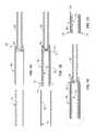
- FIGS. 1A-1Dpresent sequential side-elevational cross-sectional views depicting a loading assembly in accordance with an inventive apparatus and method for preparing a proximally-joined covered stent assembly.
- FIGS. 2A-2Bpresent sequential side-elevational cross-sectional views of a transfer assembly in accordance with the inventive apparatus and method for preparing a proximally- and distally-joined covered stent assembly.
- FIGS. 3A-3Cpresents sequential side-elevational cross-sectional views depicting loading of the inventive proximally and distally-joined covered stent assembly into a delivery catheter.
- FIGS. 4A-4Bpresents sequential side-elevational cross-sectional views depicting loading of a proximally- and distally-joined covered stent assembly into a tapered catheter sheath in accordance with an alternative preferred embodiment of the present invention.
- FIGS. 5A-5Bpresents sequential side-elevational cross-sectional views depicting catheter assembly in accordance with the alternative preferred embodiment of the present invention.
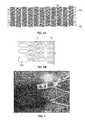
- FIG. 6Ais an expanded side view of the stent with proximal and distal junction points; and FIG. 6B is an enlarged side view of the stent with the proximal and distal junction points.
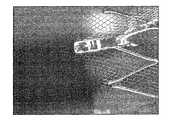
- FIG. 7is a photomicrograph illustrating a junction point of a stent welded to a cover.
- FIGS. 1A-1Ddepict the preparation of a proximally-joined covered stent using a loading/welding fixture 40 .
- FIG. 1Adepicts the loading of stent 10 into the lumen of loading sheath 30 of loading/welding fixture 40 .
- Loading/welding fixture 40consists generally of the cylindrical loading sheath 30 and a pusher rod 32 having an abutment member 34 coupled to one end of the pusher rod 32 .
- the abutment member 34is concentrically engaged within the lumen of loading sheath 30 and is capable of reciprocal movement therein.
- the abutment member 34 and pusher rod 32serve dual functions: first, the abutment member 34 acts as a stop during insertion of the stent 10 into the lumen of the loading sheath 30 to properly position the stent 10 therein, and second, the pusher rod 32 and abutment member 34 act to eject the proximally-affixed stent and cover from the lumen of the loading sheath 30 .
- FIG. 1Bdepicts the loading of cover 20 over an ablumenal surface of the loading sheath 30 .
- abutment member 34is positioned within the lumen of loading sheath 30 a distance d 2 , such that the remaining opening of the lumen of loading sheath 30 has a length of d 1 .
- Length d 1also corresponds to the degree of overhang or exposure of stent 10 from the proximal end region 31 of loading sheath 30 that is required for affixation of the cover 20 to the stent 10 .
- the cover 20is concentrically positioned over the ablumenal surface of the loading sheath 30 and a proximal end of the cover 20 is aligned with the proximal end of the stent 10 , such that the loading sheath 30 is positioned intermediate the stent 10 and the cover 20 , with the exposed proximal end 11 of the stent 10 and the proximal end 21 of the cover 20 being in adjacent proximity therebetween. Therefore, as shown in the circled portion of FIG. 1C , after cover 20 has been loaded over loading sheath 30 , the proximal end region 11 of stent 10 and proximal end region 21 of cover 20 may be joined without interference from proximal end region 31 of loading sheath 30 .
- FIG. 1Ddepicts an exploded view of the circled region of FIG. 1C , with an example of such a join between proximal end region 11 of stent 10 and proximal end region 21 of cover 20 shown by solid box 15 .
- FIG. 1Ddepicts a proximally-joined covered stent assembly comprising stent 10 contained within cover 20 with a joining point 15 between the proximal end regions of stent 10 and cover 20 .
- FIGS. 2A-2Bdepict loading the proximally joined stent 10 and cover 20 into a constraining tube 50 and the subsequent formation of a distal juncture 16 between the stent 10 and the cover 20 .
- FIG. 2Adepicts a proximally-joined covered stent assembly prepared as in FIG. 1 , which has been ejected from the loading sheath 30 by axial movement of the pusher rod 32 and the abutment member 34 within the loading sheath 30 .
- a constraining tube 50By bringing a constraining tube 50 into co-axial alignment with the loading sheath 30 , as the proximally-joined covered stent assembly is ejected from the loading sheath 30 , it is pushed into the constraining tube 50 .
- the proximally-joined covered stent assemblyis positioned in the constraining tube 50 such that the assembly extends and is exposed from the distal end of the constraining tube 50 a distance d 3 .
- the exposed distal end of the assemblypermits formation of a distal junction 16 between the stent 10 and the cover 20 .
- FIGS. 3A-3Cdepict the preparation of an assembly comprising a catheter sheath 60 , a proximally- and distally-joined covered stent 25 , a pusher member 80 , a guidewire shaft 70 and an atraumatic tip 90 .
- a proximally- and distally-joined covered stent assemblyis partially contained within a catheter sheath 60 .
- the proximally- and distally-joined covered stent assembly 25 of FIG. 3Amay be obtained as shown in FIGS. 1 and 2 .
- FIG. 3Bthe proximally- and distally-joined covered stent assembly of FIG.
- FIG. 3Ahas been pushed completely within catheter sheath 60
- FIG. 3Cthe assembly 25 of FIG. 3B
- a guidewire shaft 70is co-axially inserted through the central lumen of the covered stent assembly 25 and extends beyond the terminal (proximal) end of the pusher member 80 and the catheter sheath 60
- An atraumatic tip 90is affixed to a distal end of the guidewire shaft 70 prior to insertion of the guidewire shaft 70 .
- the atraumatic tip 90is retracted into abutting relation with a distal end of the catheter sheath 60 , thereby enclosing the covered stent assembly 25 within the catheter sheath 60 .
- cover 20is preferably in its martensitic state and unstrained at room temperature, when positioned on the loading sheath 30 .
- the stent 10is preferably austenitic and should be loaded into the loading sheath 30 in the presence of a cooling medium, e.g., liquid nitrogen bath, dry ice and alcohol bath, flow of chilled gas, etc.
- the stent in its compressed diameteris strained, thus, in order to operate the other manipulative steps, needs to be within the constraining tube 50 or the catheter tube.
- the protruding proximal or distal ends of the stentwill, however, flare slightly as they are exposed to room temperatures after being loaded into the loading sheath 30 and the constraining tube 50 . This very slight flare, however, ensures good apposition between the stent 10 and cover 20 and facilitates forming a junction between the stent 10 and the cover 20 , such as by resistance spot welding.
- FIGS. 4A-4Billustrate loading of the inventive covered stent assembly 25 into a catheter sheath 100 which acts to constrain the device from expansion.
- FIG. 4Bdepicts the proximally- and distally-joined covered stent assembly prepared as in FIGS. 1A-1D , substantially inserted into constraining tube 50 .
- FIGS. 5A-5Bdepict the steps in completing the delivery catheter assembly 120 after a pusher member 110 is pre-engaged within the catheter sheath 100 , as assembly of the pusher member 110 after the covered stent assembly 25 is in the catheter sheath 100 would be impracticable.
- the covered stent assembly 25may then be fully inserted into the catheter sheath 100 as shown in FIG. 5A , such as by using a pusher member similar to the pusher member 34 , 32 shown in FIG. 1A , such that it abuts or is immediately adjacent to the pusher member 110 .
- a guidewire shaft 122is co-axially inserted through the central lumen of the covered stent assembly 25 and extends beyond the terminal end of the pusher member 110 and the catheter sheath 100 .
- An atraumatic tip 130is affixed to a distal end of the guidewire shaft 122 prior to insertion of the guidesire shaft 122 .
- the atraumatic tip 130is retracted into abutting relation with a distal end of the catheter sheath 100 , thereby enclosing the covered stent assembly 25 within the catheter sheath 100 .
- joining points 15 or 16be formed by thermal methods, such as such as laser welding, plasma welding, resistance welding, and e-beam welding where both the stent 10 and the cover 20 are fabricated of metal or pseudometallic materials, preferably shape memory or superelastic materials, most preferably, nickel-titanium alloys.
- thermal methodssuch as laser welding, plasma welding, resistance welding, and e-beam welding where both the stent 10 and the cover 20 are fabricated of metal or pseudometallic materials, preferably shape memory or superelastic materials, most preferably, nickel-titanium alloys.
- weldingis generally not an acceptable method for joining nickel-titanium alloy to other materials, such as stainless steel, because brittle intermetallics are formed in the weld zone.
- nickel-titanium alloyis to be joined to another biocompatible material
- soldering, epoxies or adhesivesit is desirable to employ soldering, epoxies or adhesives to form the joining point 15 .
- an interlayer materialsuch as tantalum, to minimize formation of brittle intermetallics during welding.
- the stent 10it is preferably to configure the stent 10 such that it has proximal and distal junction points 150 which provide a relatively larger, substantially planar surface area for creating the junction between the cover 20 and the stent 10 .
- the junction points 150may have a generally quadrilateral shape in the X-Y axis of either the luminal or abluminal surface of the stent 10 , preferably has the same Z-axis wall thickness as the remaining portions of the stent 10 , and have a slight curvature corresponding generally to the curvature of the tubular stent 10 .
- FIG. 7is a photomicrograph illustrating a junction point 150 of a stent 10 welded to a cover 20 .
- junction points 150may be projections from terminal proximal and/or distal cylindrical members forming the tubular stent 10 (See, e.g., FIG. 1, element 11 in the '554 Publication or FIG. 27, elements 307 and 304 a - e in the '094 Publication), each publication is hereby expressly incorporated by reference.
- the stent and the coverwhen employing shape memory materials for both the stent and the cover, that the stent and the cover have different transition temperatures, such that the stent have its transition temperature below body temperature and diametrically expand when exposed to body temperature, while the cover preferably has a transition temperature above body temperature so that it undergoes detwinned martensitic plastic deformation due to expansion of the stent upon implanting into the body.
- the stenthave an A f ⁇ 29° C. ⁇ 3° C. and the cover have an have an A f between about 60 to 100° C.
- the coverremains martensitic under all conditions which are likely to be encountered during manufacture, delivery and after being implanted in vivo.
- the stenton the other hand, having an A f less than body temperature, will be constrained in the delivery catheter and readily expand during implantation in vivo, and readily expand the martensitic cover along with the radial expansion of the stent. Since the cover and the stent will be affixed to each other, it is desirable that the stent and the cover exhibit compatible degrees of foreshortening upon radial expansion of the resulting covered stent device.
- a self-expanding shape memory nickel-titanium stent having a wall thickness of 127 ⁇ m, a 0.965 mm inner diameter (“ID”) and 1.168 mm outer diameter (“OD”)is loaded into a loading sheath of 1.194 mm ID and 1.295 mm OD of a loading/welding fixture, and a cover of 1.257 mm OD and 4.5 micron wall thickness is loaded over the loading sheath.
- the proximal end region of the coveris then welded to the proximal end region of the crimped stent.
- the resulting proximally-joined covered stent assemblyis slid into the distal end of a constraining tube having a 1.193 mm ID and 1.295 mm OD.
- the loading sheath of the loading/welding fixtureis then retracted, the distal end region of the cover is welded to the distal end region of the stent, and the weld is passivated in a nitric acid solution.
- the resulting proximally- and distally-joined covered stent assemblyis then slid completely into the constant outer diameter catheter sheath.
- this assemblyis chilled in order to facilitate sliding.
- a pusher shaft of 0.031′′ ID and 0.051′′ ODis then inserted from the proximal end of the constant outer diameter catheter sheath, and a guidewire shaft of 0.018′′ ID and 0.027′′ OD comprising a proximal tip is inserted from the distal end of the constant outer diameter catheter sheath.
- the insertion of the guidewire shaftmay precede the insertion of the pusher shaft.
- a self-expanding shape memory stent having a wall thickness of 127 ⁇ mis crimped to an inner diameter (“ID”) of 0.97 mm with an outer diameter of 1.17 mm.
- IDinner diameter
- the crimped stentis then loaded into a loading sheath having a 1.19 mm ID and 1.295 mm OD of a loading/welding fixture, and a cover of 1.257 mm OD and 4.5 micron wall thickness is loaded over the loading sheath.
- the proximal end region of the coveris then welded to the proximal end region of the crimped stent.
- the resulting proximally-joined covered stent assemblyis slid into a constraining tube having a 1.193 mm ID and a 1.295 mm OD.
- the loading sheath of the loading/welding fixtureis then retracted, the distal end region of the cover is welded to the distal end region of the stent, and the weld is passivated in a nitric acid solution.
- a tapered catheter sheathhaving an ID of 1.397 mm and a 1.600 OD distally, tapered to 1.092 ID and 1.295 mm OD proximally, where this tapered catheter sheath contains a preloaded catheter pusher shaft of 0.737 mm ID and 1.295 mm OD distally, tapered to 0.737 mm ID and 0.991 mm OD proximally.
- this assemblyis chilled in order to facilitate sliding.
- a guidewire sheath of 0.457 mm ID and 0.686 mm OD and including an atraumatic tipis then inserted from the distal end of the tapered diameter catheter sheath.
Landscapes
- Health & Medical Sciences (AREA)
- Engineering & Computer Science (AREA)
- Biomedical Technology (AREA)
- General Health & Medical Sciences (AREA)
- Veterinary Medicine (AREA)
- Public Health (AREA)
- Heart & Thoracic Surgery (AREA)
- Vascular Medicine (AREA)
- Life Sciences & Earth Sciences (AREA)
- Animal Behavior & Ethology (AREA)
- Transplantation (AREA)
- Oral & Maxillofacial Surgery (AREA)
- Cardiology (AREA)
- Chemical & Material Sciences (AREA)
- Inorganic Chemistry (AREA)
- Surgery (AREA)
- Epidemiology (AREA)
- Media Introduction/Drainage Providing Device (AREA)
- Prostheses (AREA)
- Materials For Medical Uses (AREA)
Abstract
Description
Claims (13)
Priority Applications (11)
| Application Number | Priority Date | Filing Date | Title |
|---|---|---|---|
| US11/215,984US8187318B2 (en) | 2005-08-31 | 2005-08-31 | Covered stent with proximal and distal attachment, delivery catheter, and method of making same |
| EP06802660AEP1931281A4 (en) | 2005-08-31 | 2006-08-30 | Covered stent with proximal and distal attachment, delivery catheter, and method of making same |
| CNA2006800316811ACN101511306A (en) | 2005-08-31 | 2006-08-30 | Covered stent with proximal and distal attached delivery catheters and method of making same |
| AU2006284818AAU2006284818C1 (en) | 2005-08-31 | 2006-08-30 | Covered stent with proximal and distal attachment, delivery catheter, and method of making same |
| PCT/US2006/033942WO2007027829A2 (en) | 2005-08-31 | 2006-08-30 | Covered stent with proximal and distal attachment, delivery catheter, and method of making same |
| MX2008002762AMX2008002762A (en) | 2005-08-31 | 2006-08-30 | Covered stent with proximal and distal attachment, delivery catheter, and method of making same. |
| JP2008529253AJP5331479B2 (en) | 2005-08-31 | 2006-08-30 | Covered stent with proximal and distal fittings, delivery catheter and method of manufacturing the stent |
| CA2621299ACA2621299C (en) | 2005-08-31 | 2006-08-30 | Covered stent with proximal and distal attachment, delivery catheter, and method of making same |
| CA2858266ACA2858266A1 (en) | 2005-08-31 | 2006-08-30 | Covered stent with proximal and distal attachment, delivery catheter, and method of making same |
| US13/445,131US8732935B2 (en) | 2005-08-31 | 2012-04-12 | Stent-graft with proximal and distal attachment, delivery catheter and methods of making same |
| US14/288,284US20140343658A1 (en) | 2005-08-31 | 2014-05-27 | Stent-graft with proximal and distal attachment, delivery catheter and methods of making same |
Applications Claiming Priority (1)
| Application Number | Priority Date | Filing Date | Title |
|---|---|---|---|
| US11/215,984US8187318B2 (en) | 2005-08-31 | 2005-08-31 | Covered stent with proximal and distal attachment, delivery catheter, and method of making same |
Related Child Applications (1)
| Application Number | Title | Priority Date | Filing Date |
|---|---|---|---|
| US13/445,131DivisionUS8732935B2 (en) | 2005-08-31 | 2012-04-12 | Stent-graft with proximal and distal attachment, delivery catheter and methods of making same |
Publications (2)
| Publication Number | Publication Date |
|---|---|
| US20070050017A1 US20070050017A1 (en) | 2007-03-01 |
| US8187318B2true US8187318B2 (en) | 2012-05-29 |
Family
ID=37805354
Family Applications (3)
| Application Number | Title | Priority Date | Filing Date |
|---|---|---|---|
| US11/215,984Active2027-08-31US8187318B2 (en) | 2005-08-31 | 2005-08-31 | Covered stent with proximal and distal attachment, delivery catheter, and method of making same |
| US13/445,131Expired - LifetimeUS8732935B2 (en) | 2005-08-31 | 2012-04-12 | Stent-graft with proximal and distal attachment, delivery catheter and methods of making same |
| US14/288,284AbandonedUS20140343658A1 (en) | 2005-08-31 | 2014-05-27 | Stent-graft with proximal and distal attachment, delivery catheter and methods of making same |
Family Applications After (2)
| Application Number | Title | Priority Date | Filing Date |
|---|---|---|---|
| US13/445,131Expired - LifetimeUS8732935B2 (en) | 2005-08-31 | 2012-04-12 | Stent-graft with proximal and distal attachment, delivery catheter and methods of making same |
| US14/288,284AbandonedUS20140343658A1 (en) | 2005-08-31 | 2014-05-27 | Stent-graft with proximal and distal attachment, delivery catheter and methods of making same |
Country Status (8)
| Country | Link |
|---|---|
| US (3) | US8187318B2 (en) |
| EP (1) | EP1931281A4 (en) |
| JP (1) | JP5331479B2 (en) |
| CN (1) | CN101511306A (en) |
| AU (1) | AU2006284818C1 (en) |
| CA (2) | CA2621299C (en) |
| MX (1) | MX2008002762A (en) |
| WO (1) | WO2007027829A2 (en) |
Families Citing this family (29)
| Publication number | Priority date | Publication date | Assignee | Title |
|---|---|---|---|---|
| US6569194B1 (en) | 2000-12-28 | 2003-05-27 | Advanced Cardiovascular Systems, Inc. | Thermoelastic and superelastic Ni-Ti-W alloy |
| US20050251245A1 (en)* | 2004-05-05 | 2005-11-10 | Karl Sieradzki | Methods and apparatus with porous materials |
| US8425584B2 (en)* | 2006-04-21 | 2013-04-23 | W. L. Gore & Associates, Inc. | Expandable covered stent with wide range of wrinkle-free deployed diameters |
| US20080166526A1 (en)* | 2007-01-08 | 2008-07-10 | Monk Russell A | Formed panel structure |
| CA2701576C (en)* | 2007-10-17 | 2016-06-21 | Angiomed Gmbh & Co. Medizintechnik Kg | Delivery system for a self-expanding device for placement in a bodily lumen |
| EP2633823B1 (en) | 2008-04-21 | 2016-06-01 | Covidien LP | Braid-ball embolic devices and delivery systems |
| GB0815339D0 (en)* | 2008-08-21 | 2008-10-01 | Angiomed Ag | Method of loading a stent into a sheath |
| CA2720466A1 (en)* | 2008-05-09 | 2009-11-12 | Juergen Dorn | Method of loading a stent into a sheath |
| WO2009140437A1 (en) | 2008-05-13 | 2009-11-19 | Nfocus Neuromedical, Inc. | Braid implant delivery systems |
| US9179918B2 (en) | 2008-07-22 | 2015-11-10 | Covidien Lp | Vascular remodeling device |
| GB0823716D0 (en)* | 2008-12-31 | 2009-02-04 | Angiomed Ag | Stent delivery device with rolling stent retaining sheath |
| US9011511B2 (en)* | 2009-02-20 | 2015-04-21 | Boston Scientific Scimed, Inc. | Balloon catheter |
| GB0921237D0 (en)* | 2009-12-03 | 2010-01-20 | Angiomed Ag | Stent device delivery system and method of making such |
| GB0921236D0 (en)* | 2009-12-03 | 2010-01-20 | Angiomed Ag | Stent device delivery system and method of making such |
| GB0921238D0 (en) | 2009-12-03 | 2010-01-20 | Angiomed Ag | Stent device delivery system and method of making such |
| GB0921240D0 (en) | 2009-12-03 | 2010-01-20 | Angiomed Ag | Stent device delivery system and method of making such |
| WO2011094638A1 (en) | 2010-01-28 | 2011-08-04 | Micro Therapeutics, Inc. | Vascular remodeling device |
| GB201020373D0 (en) | 2010-12-01 | 2011-01-12 | Angiomed Ag | Device to release a self-expanding implant |
| JP5868432B2 (en) | 2011-02-11 | 2016-02-24 | コヴィディエン リミテッド パートナーシップ | Two-stage deployed aneurysm embolization device |
| US20120245674A1 (en) | 2011-03-25 | 2012-09-27 | Tyco Healthcare Group Lp | Vascular remodeling device |
| US9060886B2 (en) | 2011-09-29 | 2015-06-23 | Covidien Lp | Vascular remodeling device |
| US9399262B2 (en)* | 2011-12-15 | 2016-07-26 | Lake Region Manufacturing, Inc. | Method of joining titanium and titanium-based alloys to ferrous metals using tantalum |
| US9314248B2 (en) | 2012-11-06 | 2016-04-19 | Covidien Lp | Multi-pivot thrombectomy device |
| US9295571B2 (en)* | 2013-01-17 | 2016-03-29 | Covidien Lp | Methods and apparatus for luminal stenting |
| US9463105B2 (en) | 2013-03-14 | 2016-10-11 | Covidien Lp | Methods and apparatus for luminal stenting |
| US10736758B2 (en) | 2013-03-15 | 2020-08-11 | Covidien | Occlusive device |
| US10478194B2 (en) | 2015-09-23 | 2019-11-19 | Covidien Lp | Occlusive devices |
| WO2017215427A1 (en)* | 2016-06-12 | 2017-12-21 | 上海微创医疗器械(集团)有限公司 | Restriction apparatus, stent system, and method for using restriction apparatus |
| CN107488345B (en)* | 2016-06-12 | 2020-08-25 | 上海微创医疗器械(集团)有限公司 | Device, stent binding device and stent binding method |
Citations (18)
| Publication number | Priority date | Publication date | Assignee | Title |
|---|---|---|---|---|
| US5667523A (en)* | 1995-04-28 | 1997-09-16 | Impra, Inc. | Dual supported intraluminal graft |
| US5800517A (en) | 1996-08-19 | 1998-09-01 | Scimed Life Systems, Inc. | Stent delivery system with storage sleeve |
| EP0960607A1 (en) | 1998-05-28 | 1999-12-01 | Medtronic Ave, Inc. | Endoluminal support assembly with capped ends |
| US6123723A (en)* | 1998-02-26 | 2000-09-26 | Board Of Regents, The University Of Texas System | Delivery system and method for depolyment and endovascular assembly of multi-stage stent graft |
| US6179878B1 (en)* | 1996-10-22 | 2001-01-30 | Thomas Duerig | Composite self expanding stent device having a restraining element |
| US6214039B1 (en)* | 1995-08-24 | 2001-04-10 | Impra, Inc., A Subsidiary Of C. R. Bard, Inc. | Covered endoluminal stent and method of assembly |
| US6254632B1 (en) | 2000-09-28 | 2001-07-03 | Advanced Cardiovascular Systems, Inc. | Implantable medical device having protruding surface structures for drug delivery and cover attachment |
| US6413269B1 (en) | 2000-07-06 | 2002-07-02 | Endocare, Inc. | Stent delivery system |
| US6451052B1 (en)* | 1994-05-19 | 2002-09-17 | Scimed Life Systems, Inc. | Tissue supporting devices |
| WO2003013337A2 (en) | 2001-08-07 | 2003-02-20 | Advanced Bio Prosthetic Surfaces, Ltd. | Medical grafts having plurality of microperforations |
| US20030130718A1 (en)* | 1999-11-19 | 2003-07-10 | Palmas Julio C. | Endoluminal implantable stent-grafts |
| US6699277B1 (en)* | 2000-03-09 | 2004-03-02 | Diseno Y Desarrollo Medica, S.A. De C.V. | Stent with cover connectors |
| US20040093066A1 (en)* | 2002-09-26 | 2004-05-13 | Durcan Jonathan P. | Balloon expandable stent |
| US20040098094A1 (en)* | 2002-09-26 | 2004-05-20 | Boyle Christopher T. | Implantable graft and methods of making same |
| US20040186550A1 (en)* | 2003-03-20 | 2004-09-23 | Craig Bonsignore | Anvil bridge stent design |
| US6800089B1 (en)* | 2000-05-31 | 2004-10-05 | Advanced Cardiovascular Systems, Inc. | Mechanical attachment method of cover materials on stents |
| US20060259131A1 (en)* | 2005-05-16 | 2006-11-16 | Masoud Molaei | Medical devices including metallic films and methods for making same |
| US20070112415A1 (en)* | 1999-07-16 | 2007-05-17 | Abbott Laboratories | Braided stent |
Family Cites Families (22)
| Publication number | Priority date | Publication date | Assignee | Title |
|---|---|---|---|---|
| US4416028A (en)* | 1981-01-22 | 1983-11-22 | Ingvar Eriksson | Blood vessel prosthesis |
| US4604762A (en)* | 1981-02-13 | 1986-08-12 | Thoratec Laboratories Corporation | Arterial graft prosthesis |
| US5102417A (en)* | 1985-11-07 | 1992-04-07 | Expandable Grafts Partnership | Expandable intraluminal graft, and method and apparatus for implanting an expandable intraluminal graft |
| US4816339A (en)* | 1987-04-28 | 1989-03-28 | Baxter International Inc. | Multi-layered poly(tetrafluoroethylene)/elastomer materials useful for in vivo implantation |
| US4969896A (en)* | 1989-02-01 | 1990-11-13 | Interpore International | Vascular graft prosthesis and method of making the same |
| US4955899A (en)* | 1989-05-26 | 1990-09-11 | Impra, Inc. | Longitudinally compliant vascular graft |
| DE3918736C2 (en) | 1989-06-08 | 1998-05-14 | Christian Dr Vallbracht | Plastic-coated metal mesh stents |
| US5084065A (en)* | 1989-07-10 | 1992-01-28 | Corvita Corporation | Reinforced graft assembly |
| US5630840A (en)* | 1993-01-19 | 1997-05-20 | Schneider (Usa) Inc | Clad composite stent |
| US5334201A (en)* | 1993-03-12 | 1994-08-02 | Cowan Kevin P | Permanent stent made of a cross linkable material |
| US5735892A (en)* | 1993-08-18 | 1998-04-07 | W. L. Gore & Associates, Inc. | Intraluminal stent graft |
| US5507769A (en) | 1994-10-18 | 1996-04-16 | Stentco, Inc. | Method and apparatus for forming an endoluminal bifurcated graft |
| AU719980B2 (en)* | 1995-02-22 | 2000-05-18 | Menlo Care, Inc. | Covered expanding mesh stent |
| US6124523A (en)* | 1995-03-10 | 2000-09-26 | Impra, Inc. | Encapsulated stent |
| JP3094832B2 (en)* | 1995-03-24 | 2000-10-03 | 三菱電機株式会社 | Signal discriminator |
| US5954764A (en)* | 1996-09-20 | 1999-09-21 | Parodi; Juan Carlos | Device for concurrently placing an endovascular expander with an endovascular prosthesis |
| US5824045A (en)* | 1996-10-21 | 1998-10-20 | Inflow Dynamics Inc. | Vascular and endoluminal stents |
| EP0975279B1 (en)* | 1997-04-15 | 2007-05-02 | Schneider (Usa) Inc. | Prostheses with selectively welded crossing strands |
| US6322585B1 (en)* | 1998-11-16 | 2001-11-27 | Endotex Interventional Systems, Inc. | Coiled-sheet stent-graft with slidable exo-skeleton |
| AU2001240956A1 (en)* | 2000-03-09 | 2001-09-17 | Diseno Y Desarrollo Medico, S.A. De C.V. | Stent with cover connectors |
| US7399312B2 (en)* | 2001-10-10 | 2008-07-15 | Scimed Life Systems, Inc. | Stent design with sheath attachment members |
| US7744641B2 (en)* | 2004-07-21 | 2010-06-29 | Boston Scientific Scimed, Inc. | Expandable framework with overlapping connectors |
- 2005
- 2005-08-31USUS11/215,984patent/US8187318B2/enactiveActive
- 2006
- 2006-08-30AUAU2006284818Apatent/AU2006284818C1/ennot_activeCeased
- 2006-08-30CACA2621299Apatent/CA2621299C/ennot_activeExpired - Fee Related
- 2006-08-30EPEP06802660Apatent/EP1931281A4/ennot_activeWithdrawn
- 2006-08-30CNCNA2006800316811Apatent/CN101511306A/enactivePending
- 2006-08-30JPJP2008529253Apatent/JP5331479B2/ennot_activeExpired - Fee Related
- 2006-08-30CACA2858266Apatent/CA2858266A1/ennot_activeAbandoned
- 2006-08-30WOPCT/US2006/033942patent/WO2007027829A2/enactiveApplication Filing
- 2006-08-30MXMX2008002762Apatent/MX2008002762A/enactiveIP Right Grant
- 2012
- 2012-04-12USUS13/445,131patent/US8732935B2/ennot_activeExpired - Lifetime
- 2014
- 2014-05-27USUS14/288,284patent/US20140343658A1/ennot_activeAbandoned
Patent Citations (19)
| Publication number | Priority date | Publication date | Assignee | Title |
|---|---|---|---|---|
| US6451052B1 (en)* | 1994-05-19 | 2002-09-17 | Scimed Life Systems, Inc. | Tissue supporting devices |
| US5667523A (en)* | 1995-04-28 | 1997-09-16 | Impra, Inc. | Dual supported intraluminal graft |
| US6214039B1 (en)* | 1995-08-24 | 2001-04-10 | Impra, Inc., A Subsidiary Of C. R. Bard, Inc. | Covered endoluminal stent and method of assembly |
| US5800517A (en) | 1996-08-19 | 1998-09-01 | Scimed Life Systems, Inc. | Stent delivery system with storage sleeve |
| US6179878B1 (en)* | 1996-10-22 | 2001-01-30 | Thomas Duerig | Composite self expanding stent device having a restraining element |
| US6123723A (en)* | 1998-02-26 | 2000-09-26 | Board Of Regents, The University Of Texas System | Delivery system and method for depolyment and endovascular assembly of multi-stage stent graft |
| EP0960607A1 (en) | 1998-05-28 | 1999-12-01 | Medtronic Ave, Inc. | Endoluminal support assembly with capped ends |
| US20070112415A1 (en)* | 1999-07-16 | 2007-05-17 | Abbott Laboratories | Braided stent |
| US20030130718A1 (en)* | 1999-11-19 | 2003-07-10 | Palmas Julio C. | Endoluminal implantable stent-grafts |
| US7300457B2 (en)* | 1999-11-19 | 2007-11-27 | Advanced Bio Prosthetic Surfaces, Ltd. | Self-supporting metallic implantable grafts, compliant implantable medical devices and methods of making same |
| US6699277B1 (en)* | 2000-03-09 | 2004-03-02 | Diseno Y Desarrollo Medica, S.A. De C.V. | Stent with cover connectors |
| US6800089B1 (en)* | 2000-05-31 | 2004-10-05 | Advanced Cardiovascular Systems, Inc. | Mechanical attachment method of cover materials on stents |
| US6413269B1 (en) | 2000-07-06 | 2002-07-02 | Endocare, Inc. | Stent delivery system |
| US6254632B1 (en) | 2000-09-28 | 2001-07-03 | Advanced Cardiovascular Systems, Inc. | Implantable medical device having protruding surface structures for drug delivery and cover attachment |
| WO2003013337A2 (en) | 2001-08-07 | 2003-02-20 | Advanced Bio Prosthetic Surfaces, Ltd. | Medical grafts having plurality of microperforations |
| US20040093066A1 (en)* | 2002-09-26 | 2004-05-13 | Durcan Jonathan P. | Balloon expandable stent |
| US20040098094A1 (en)* | 2002-09-26 | 2004-05-20 | Boyle Christopher T. | Implantable graft and methods of making same |
| US20040186550A1 (en)* | 2003-03-20 | 2004-09-23 | Craig Bonsignore | Anvil bridge stent design |
| US20060259131A1 (en)* | 2005-05-16 | 2006-11-16 | Masoud Molaei | Medical devices including metallic films and methods for making same |
Non-Patent Citations (1)
| Title |
|---|
| European Search Report, pp. 1-6 (Mar. 16, 2010). |
Also Published As
| Publication number | Publication date |
|---|---|
| US20070050017A1 (en) | 2007-03-01 |
| US20140343658A1 (en) | 2014-11-20 |
| WO2007027829A2 (en) | 2007-03-08 |
| JP5331479B2 (en) | 2013-10-30 |
| US8732935B2 (en) | 2014-05-27 |
| AU2006284818B2 (en) | 2012-08-23 |
| CA2858266A1 (en) | 2007-03-08 |
| MX2008002762A (en) | 2008-04-07 |
| AU2006284818C1 (en) | 2013-04-04 |
| EP1931281A2 (en) | 2008-06-18 |
| US20120197381A1 (en) | 2012-08-02 |
| EP1931281A4 (en) | 2010-04-14 |
| CA2621299A1 (en) | 2007-03-08 |
| CA2621299C (en) | 2014-11-04 |
| AU2006284818A1 (en) | 2007-03-08 |
| CN101511306A (en) | 2009-08-19 |
| WO2007027829A3 (en) | 2009-04-30 |
| JP2009509569A (en) | 2009-03-12 |
Similar Documents
| Publication | Publication Date | Title |
|---|---|---|
| CA2621299C (en) | Covered stent with proximal and distal attachment, delivery catheter, and method of making same | |
| JP5096118B2 (en) | Stent delivery system | |
| US7695507B2 (en) | Neurovascular stent and method | |
| EP1334701B1 (en) | Tubular medical prostheses | |
| JP4940386B2 (en) | Stent with end member having lateral extension | |
| US8034099B2 (en) | Stent prosthesis having select flared crowns | |
| JP4601738B2 (en) | Self-expanding stent feeder | |
| US7717949B2 (en) | Lining for bodily lumen | |
| JP2002102356A (en) | A delivery apparatus for self-expanding stent | |
| US20070179519A1 (en) | Stent delivery system to improve placement accuracy for self-expanding stent | |
| JP2004358242A (en) | Improved radiopacity intraluminal medical device | |
| CA2392250A1 (en) | Detachable covering for an implantable medical device | |
| JP2008513109A (en) | Atraumatic bonding for multicomponent stents | |
| US20070142900A1 (en) | Stent including a portal and methods of use thereof | |
| AU2012258286B2 (en) | Covered stent with proximal and distal attachment, delivery catheter, and method of making same |
Legal Events
| Date | Code | Title | Description |
|---|---|---|---|
| AS | Assignment | Owner name:ADVANCED BIO PROSTHETIC SURFACES, LTD., TEXAS Free format text:ASSIGNMENT OF ASSIGNORS INTEREST;ASSIGNORS:SIMS, DANIEL D.;STEINMETZ, JEFFREY N.;MULLENS, CONOR P.;REEL/FRAME:017019/0968 Effective date:20050922 | |
| STCF | Information on status: patent grant | Free format text:PATENTED CASE | |
| AS | Assignment | Owner name:SPI DALLAS INVESTMENTS, LP, TEXAS Free format text:SECURITY INTEREST;ASSIGNORS:PALMAZ SCIENTIFIC INC.;ADVANCED BIO PROSTHETIC SURFACES, LTD.;ABPS VENTURE ONE, LTD.;REEL/FRAME:036384/0818 Effective date:20150722 | |
| AS | Assignment | Owner name:SPI DALLAS INVESTMENTS, LP, TEXAS Free format text:SECURITY INTEREST;ASSIGNORS:PALMAZ SCIENTIFIC INC.;ADVANCED BIO PROSTHETIC SURFACES, LTD.;ABPS VENTURE ONE, LTD.;REEL/FRAME:036434/0813 Effective date:20150722 Owner name:LENNOX CAPITAL PARTNERS, LP, TEXAS Free format text:CORRECTIVE ASSIGNMENT TO CORRECT THE NAME OF ASSIGNEE PREVIOUSLY RECORDED AT REEL: 036384 FRAME: 0818. ASSIGNOR(S) HEREBY CONFIRMS THE SECURITY INTEREST;ASSIGNORS:PALMAZ SCIENTIFIC INC.;ADVANCED BIO PROSTHETIC SURFACES, LTD.;ABPS VENTURE ONE, LTD.;REEL/FRAME:036465/0091 Effective date:20150722 | |
| FPAY | Fee payment | Year of fee payment:4 | |
| SULP | Surcharge for late payment | ||
| AS | Assignment | Owner name:PALMAZ, JULIO, CALIFORNIA Free format text:SECURITY INTEREST;ASSIGNORS:PALMAZ SCIENTIFIC INC.;ADVANCED BIO PROSTHETIC SURFACES, LTD.;ABPS VENTURE ONE, LTD.;REEL/FRAME:037820/0400 Effective date:20150917 | |
| AS | Assignment | Owner name:OAK COURT PARTNERS, LTD., NEVADA Free format text:SECURITY INTEREST;ASSIGNORS:PALMAZ SCIENTIFIC INC.;ADVANCED BIO PROSTHETIC SURFACES, LTD.;ABPS VENTURE ONE, LTD.;REEL/FRAME:037827/0568 Effective date:20150917 Owner name:OAK COURT PARTNERS, LTD., NEVADA Free format text:SECURITY INTEREST;ASSIGNORS:PALMAZ SCIENTIFIC INC.;ADVANCED BIO PROSTHETIC SURFACES, LTD.;ABPS VENTURE ONE, LTD.;REEL/FRAME:037836/0646 Effective date:20150917 | |
| AS | Assignment | Owner name:OAK COURT PARTNERS, LTD., TEXAS Free format text:SECURITY INTEREST;ASSIGNORS:PALMAZ SCIENTIFIC INC.;ADVANCED BIO PROSTHETIC SURFACES, LTD.;ABPS VENTURE ONE, LTD.;REEL/FRAME:037839/0278 Effective date:20151230 | |
| AS | Assignment | Owner name:VACTRONIX SCIENTIFIC, INC., CALIFORNIA Free format text:ASSIGNMENT OF ASSIGNORS INTEREST;ASSIGNOR:ADVANCED BIO PROSTHETIC SURFACES, LTD.;REEL/FRAME:042117/0331 Effective date:20160805 | |
| AS | Assignment | Owner name:VACTRONIX SCIENTIFIC, LLC, TEXAS Free format text:ASSIGNMENT OF ASSIGNORS INTEREST;ASSIGNOR:VACTRONIX SCIENTIFIC, INC.;REEL/FRAME:045846/0917 Effective date:20180516 | |
| MAFP | Maintenance fee payment | Free format text:PAYMENT OF MAINTENANCE FEE, 8TH YR, SMALL ENTITY (ORIGINAL EVENT CODE: M2552); ENTITY STATUS OF PATENT OWNER: SMALL ENTITY Year of fee payment:8 | |
| MAFP | Maintenance fee payment | Free format text:PAYMENT OF MAINTENANCE FEE, 12TH YR, SMALL ENTITY (ORIGINAL EVENT CODE: M2553); ENTITY STATUS OF PATENT OWNER: SMALL ENTITY Year of fee payment:12 |