US8187315B1 - Partial stent for treatment of a vascular aneurysm - Google Patents
Partial stent for treatment of a vascular aneurysmDownload PDFInfo
- Publication number
- US8187315B1 US8187315B1US11/608,435US60843506AUS8187315B1US 8187315 B1US8187315 B1US 8187315B1US 60843506 AUS60843506 AUS 60843506AUS 8187315 B1US8187315 B1US 8187315B1
- Authority
- US
- United States
- Prior art keywords
- ribs
- partial stent
- backbone
- stent
- partial
- Prior art date
- Legal status (The legal status is an assumption and is not a legal conclusion. Google has not performed a legal analysis and makes no representation as to the accuracy of the status listed.)
- Active, expires
Links
- 206010002329AneurysmDiseases0.000titleabstractdescription46
- 239000000463materialSubstances0.000claimsdescription7
- 239000012528membraneSubstances0.000claimsdescription3
- 210000004204blood vesselAnatomy0.000abstractdescription26
- 201000008450Intracranial aneurysmDiseases0.000abstractdescription13
- 210000005166vasculatureAnatomy0.000description16
- 238000000034methodMethods0.000description8
- 210000001519tissueAnatomy0.000description8
- 210000004556brainAnatomy0.000description6
- 239000008280bloodSubstances0.000description5
- 210000004369bloodAnatomy0.000description5
- 208000006011StrokeDiseases0.000description4
- 230000035515penetrationEffects0.000description4
- 230000002792vascularEffects0.000description4
- 210000001367arteryAnatomy0.000description3
- 229920001343polytetrafluoroethylenePolymers0.000description3
- 239000004810polytetrafluoroethyleneSubstances0.000description3
- 238000004873anchoringMethods0.000description2
- 150000001875compoundsChemical class0.000description2
- 238000002594fluoroscopyMethods0.000description2
- 238000003384imaging methodMethods0.000description2
- 210000003657middle cerebral arteryAnatomy0.000description2
- 229910001000nickel titaniumInorganic materials0.000description2
- 239000002994raw materialSubstances0.000description2
- 239000010935stainless steelSubstances0.000description2
- 229910001220stainless steelInorganic materials0.000description2
- 229920004934Dacron®Polymers0.000description1
- 208000016988Hemorrhagic StrokeDiseases0.000description1
- 208000028389Nerve injuryDiseases0.000description1
- 208000031481Pathologic ConstrictionDiseases0.000description1
- FAPWRFPIFSIZLT-UHFFFAOYSA-MSodium chlorideChemical compound[Na+].[Cl-]FAPWRFPIFSIZLT-UHFFFAOYSA-M0.000description1
- 208000007536ThrombosisDiseases0.000description1
- 206010047163VasospasmDiseases0.000description1
- 230000002159abnormal effectEffects0.000description1
- 239000000853adhesiveSubstances0.000description1
- 230000001070adhesive effectEffects0.000description1
- 238000002583angiographyMethods0.000description1
- 230000001028anti-proliverative effectEffects0.000description1
- 230000000740bleeding effectEffects0.000description1
- 230000017531blood circulationEffects0.000description1
- 210000001715carotid arteryAnatomy0.000description1
- 230000002490cerebral effectEffects0.000description1
- 210000000275circle of willisAnatomy0.000description1
- 230000004087circulationEffects0.000description1
- 230000035602clottingEffects0.000description1
- 238000010276constructionMethods0.000description1
- 238000002788crimpingMethods0.000description1
- 230000010339dilationEffects0.000description1
- 239000013013elastic materialSubstances0.000description1
- 210000001105femoral arteryAnatomy0.000description1
- 210000004013groinAnatomy0.000description1
- 208000003906hydrocephalusDiseases0.000description1
- 208000020658intracerebral hemorrhageDiseases0.000description1
- 238000003698laser cuttingMethods0.000description1
- 238000003754machiningMethods0.000description1
- 230000007246mechanismEffects0.000description1
- 238000012986modificationMethods0.000description1
- 230000004048modificationEffects0.000description1
- 238000000465mouldingMethods0.000description1
- 230000008764nerve damageEffects0.000description1
- 230000000149penetrating effectEffects0.000description1
- 229920000728polyesterPolymers0.000description1
- 229920000642polymerPolymers0.000description1
- -1polytetrafluoroethylenePolymers0.000description1
- 210000003625skullAnatomy0.000description1
- 230000036262stenosisEffects0.000description1
- 208000037804stenosisDiseases0.000description1
- 238000011477surgical interventionMethods0.000description1
- 238000002560therapeutic procedureMethods0.000description1
- 230000000699topical effectEffects0.000description1
- 230000007704transitionEffects0.000description1
- 210000003462veinAnatomy0.000description1
- 238000012800visualizationMethods0.000description1
Images


Classifications
- A—HUMAN NECESSITIES
- A61—MEDICAL OR VETERINARY SCIENCE; HYGIENE
- A61F—FILTERS IMPLANTABLE INTO BLOOD VESSELS; PROSTHESES; DEVICES PROVIDING PATENCY TO, OR PREVENTING COLLAPSING OF, TUBULAR STRUCTURES OF THE BODY, e.g. STENTS; ORTHOPAEDIC, NURSING OR CONTRACEPTIVE DEVICES; FOMENTATION; TREATMENT OR PROTECTION OF EYES OR EARS; BANDAGES, DRESSINGS OR ABSORBENT PADS; FIRST-AID KITS
- A61F2/00—Filters implantable into blood vessels; Prostheses, i.e. artificial substitutes or replacements for parts of the body; Appliances for connecting them with the body; Devices providing patency to, or preventing collapsing of, tubular structures of the body, e.g. stents
- A61F2/82—Devices providing patency to, or preventing collapsing of, tubular structures of the body, e.g. stents
- A61F2/86—Stents in a form characterised by the wire-like elements; Stents in the form characterised by a net-like or mesh-like structure
- A61F2/90—Stents in a form characterised by the wire-like elements; Stents in the form characterised by a net-like or mesh-like structure characterised by a net-like or mesh-like structure
- A—HUMAN NECESSITIES
- A61—MEDICAL OR VETERINARY SCIENCE; HYGIENE
- A61B—DIAGNOSIS; SURGERY; IDENTIFICATION
- A61B17/00—Surgical instruments, devices or methods
- A61B17/02—Surgical instruments, devices or methods for holding wounds open, e.g. retractors; Tractors
- A—HUMAN NECESSITIES
- A61—MEDICAL OR VETERINARY SCIENCE; HYGIENE
- A61B—DIAGNOSIS; SURGERY; IDENTIFICATION
- A61B17/00—Surgical instruments, devices or methods
- A61B17/02—Surgical instruments, devices or methods for holding wounds open, e.g. retractors; Tractors
- A61B17/0206—Surgical instruments, devices or methods for holding wounds open, e.g. retractors; Tractors with antagonistic arms as supports for retractor elements
- A—HUMAN NECESSITIES
- A61—MEDICAL OR VETERINARY SCIENCE; HYGIENE
- A61B—DIAGNOSIS; SURGERY; IDENTIFICATION
- A61B17/00—Surgical instruments, devices or methods
- A61B17/12—Surgical instruments, devices or methods for ligaturing or otherwise compressing tubular parts of the body, e.g. blood vessels or umbilical cord
- A61B17/12022—Occluding by internal devices, e.g. balloons or releasable wires
- A61B17/12099—Occluding by internal devices, e.g. balloons or releasable wires characterised by the location of the occluder
- A61B17/12109—Occluding by internal devices, e.g. balloons or releasable wires characterised by the location of the occluder in a blood vessel
- A61B17/12113—Occluding by internal devices, e.g. balloons or releasable wires characterised by the location of the occluder in a blood vessel within an aneurysm
- A61B17/12118—Occluding by internal devices, e.g. balloons or releasable wires characterised by the location of the occluder in a blood vessel within an aneurysm for positioning in conjunction with a stent
- A—HUMAN NECESSITIES
- A61—MEDICAL OR VETERINARY SCIENCE; HYGIENE
- A61B—DIAGNOSIS; SURGERY; IDENTIFICATION
- A61B17/00—Surgical instruments, devices or methods
- A61B17/12—Surgical instruments, devices or methods for ligaturing or otherwise compressing tubular parts of the body, e.g. blood vessels or umbilical cord
- A61B17/12022—Occluding by internal devices, e.g. balloons or releasable wires
- A61B17/12131—Occluding by internal devices, e.g. balloons or releasable wires characterised by the type of occluding device
- A61B17/12168—Occluding by internal devices, e.g. balloons or releasable wires characterised by the type of occluding device having a mesh structure
- A61B17/12172—Occluding by internal devices, e.g. balloons or releasable wires characterised by the type of occluding device having a mesh structure having a pre-set deployed three-dimensional shape
- A—HUMAN NECESSITIES
- A61—MEDICAL OR VETERINARY SCIENCE; HYGIENE
- A61F—FILTERS IMPLANTABLE INTO BLOOD VESSELS; PROSTHESES; DEVICES PROVIDING PATENCY TO, OR PREVENTING COLLAPSING OF, TUBULAR STRUCTURES OF THE BODY, e.g. STENTS; ORTHOPAEDIC, NURSING OR CONTRACEPTIVE DEVICES; FOMENTATION; TREATMENT OR PROTECTION OF EYES OR EARS; BANDAGES, DRESSINGS OR ABSORBENT PADS; FIRST-AID KITS
- A61F2/00—Filters implantable into blood vessels; Prostheses, i.e. artificial substitutes or replacements for parts of the body; Appliances for connecting them with the body; Devices providing patency to, or preventing collapsing of, tubular structures of the body, e.g. stents
- A61F2/82—Devices providing patency to, or preventing collapsing of, tubular structures of the body, e.g. stents
- A61F2002/823—Stents, different from stent-grafts, adapted to cover an aneurysm
- A—HUMAN NECESSITIES
- A61—MEDICAL OR VETERINARY SCIENCE; HYGIENE
- A61F—FILTERS IMPLANTABLE INTO BLOOD VESSELS; PROSTHESES; DEVICES PROVIDING PATENCY TO, OR PREVENTING COLLAPSING OF, TUBULAR STRUCTURES OF THE BODY, e.g. STENTS; ORTHOPAEDIC, NURSING OR CONTRACEPTIVE DEVICES; FOMENTATION; TREATMENT OR PROTECTION OF EYES OR EARS; BANDAGES, DRESSINGS OR ABSORBENT PADS; FIRST-AID KITS
- A61F2220/00—Fixations or connections for prostheses classified in groups A61F2/00 - A61F2/26 or A61F2/82 or A61F9/00 or A61F11/00 or subgroups thereof
- A61F2220/0008—Fixation appliances for connecting prostheses to the body
- A61F2220/0016—Fixation appliances for connecting prostheses to the body with sharp anchoring protrusions, e.g. barbs, pins, spikes
- A—HUMAN NECESSITIES
- A61—MEDICAL OR VETERINARY SCIENCE; HYGIENE
- A61F—FILTERS IMPLANTABLE INTO BLOOD VESSELS; PROSTHESES; DEVICES PROVIDING PATENCY TO, OR PREVENTING COLLAPSING OF, TUBULAR STRUCTURES OF THE BODY, e.g. STENTS; ORTHOPAEDIC, NURSING OR CONTRACEPTIVE DEVICES; FOMENTATION; TREATMENT OR PROTECTION OF EYES OR EARS; BANDAGES, DRESSINGS OR ABSORBENT PADS; FIRST-AID KITS
- A61F2230/00—Geometry of prostheses classified in groups A61F2/00 - A61F2/26 or A61F2/82 or A61F9/00 or A61F11/00 or subgroups thereof
- A61F2230/0002—Two-dimensional shapes, e.g. cross-sections
- A61F2230/0028—Shapes in the form of latin or greek characters
- A61F2230/0034—D-shaped
- A—HUMAN NECESSITIES
- A61—MEDICAL OR VETERINARY SCIENCE; HYGIENE
- A61F—FILTERS IMPLANTABLE INTO BLOOD VESSELS; PROSTHESES; DEVICES PROVIDING PATENCY TO, OR PREVENTING COLLAPSING OF, TUBULAR STRUCTURES OF THE BODY, e.g. STENTS; ORTHOPAEDIC, NURSING OR CONTRACEPTIVE DEVICES; FOMENTATION; TREATMENT OR PROTECTION OF EYES OR EARS; BANDAGES, DRESSINGS OR ABSORBENT PADS; FIRST-AID KITS
- A61F2230/00—Geometry of prostheses classified in groups A61F2/00 - A61F2/26 or A61F2/82 or A61F9/00 or A61F11/00 or subgroups thereof
- A61F2230/0063—Three-dimensional shapes
- A61F2230/0095—Saddle-shaped
Definitions
- the inventionrelates to an apparatus and method for treating a vascular aneurysm.
- An aneurysmis an abnormal ballooning or dilation of a blood vessel.
- a cerebral aneurysmis an aneurysm in an artery or vein in the brain. Cerebral aneurysms are more common in adults than in children and more common in women than in men. Cerebral aneurysms commonly arise at the bifurcations of major arteries; most cerebral aneurysms arise on the circle of Willis (where several arteries join near the bottom of the brain) or the middle cerebral artery (MCA) bifurcation.
- MCAmiddle cerebral artery
- a common complication of a cerebral aneurysmis rupture, which results in profuse bleeding and causes serious complications including hemorrhagic stroke, permanent nerve damage, hydrocephalus, vasospasm, and/or death.
- Another complication of a cerebral aneurysmis stroke. Blood pools in the aneurysm, where it becomes isolated from the flow of blood in the brain and subsequently clots. Clots of various sizes can then break off, escape from the cerebral aneurysm into the cerebral vasculature and lodge downstream, causing a stroke.
- the aneurysmis clipped from outside before or after it bursts to isolate the aneurysm from the vasculature.
- clippingrequires highly invasive surgical intervention in the brain through the skull.
- clipping the aneurysm after it burstsdoes nothing to prevent the potentially-fatal consequences of rupture. It is preferable to treat the aneurysm before it bursts, because patients who receive treatment for an unruptured aneurysm generally require less therapy and recover more quickly.
- the aneurysmis filled with wire coils.
- Conventional catheterization techniquesare used to insert a catheter into the patient's vasculature at a location outside the brain, such as the groin or the neck, and advance the catheter to the aneurysm using angiography, after which the coils are delivered through the catheter to the aneurysm.
- the coilsfill the aneurysm before it bursts, block it from circulation, and cause the blood to clot.
- the coilsmay become dislodged from the aneurysm and enter the vasculature, causing stroke in the same manner as blood clots that become dislodged from the aneurysm. Further, smaller clots may still break off and escape from the cerebral aneurysm, resulting in stroke.
- FIG. 1is a side view of a partial stent that includes a cover.
- FIG. 2is a side view of the partial stent of FIG. 1 with the cover removed for clarity.
- FIG. 3is an end view of the partial stent of FIG. 1 .
- FIG. 4is a top view of the partial stent of FIG. 1 with the cover removed for clarity.
- FIG. 5is a perspective view of the partial stent of FIG. 1 with the cover removed for clarity.
- FIG. 6is a perspective view of the partial stent of FIG. 1 .
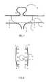
- FIG. 7is a cutaway view of the partial stent after placement at an exemplary location on in a patient's vasculature.
- FIG. 8is a cross-section view of the partial stent along line A-A of FIG. 7 after placement in a patient's vasculature.
- partial stent 2refers to a stent that, unlike a conventional coronary stent, does not describe a complete circumference when viewed on end. Instead, when viewed on end, the partial stent 2 is generally arc-shaped.
- the partial stent 2is sized and shaped to allow delivery via a standard catheter, as described in greater detail below. Alternately, the partial stent 2 may be sized and/or shaped differently.
- the partial stent 2includes a backbone 4 .
- the backbone 4may be shaped in any suitable manner.
- the backbone 4is generally linear, with a length substantially larger than its width or thickness.
- the backbone 4may be generally parallel to the longitudinal centerline of the partial stent 2 .
- the backbone 4may be curved along a tortuous or non-tortuous path.
- the backbone 4is flexible, at least in part, to allow delivery of the partial stent 2 to a treatment site via catheter.
- the entire backbone 4may be flexible, as a consequence of the material from which the backbone 4 is fabricated, as well as the thickness and shape of the backbone 4 .
- the backbone 4may include substantially rigid segments connected by substantially flexible segments, such that the backbone 4 overall is flexible.
- the partial stent 2may be small enough that the backbone 4 may be rigid.
- one or more long ribs 6may extend from the backbone 4 .
- the long ribs 6may be substantially as wide as the backbone 4 . Alternately, at least one of the long ribs 6 may be wider or narrower than the backbone 4 .
- the long ribs 6extend substantially perpendicularly from the backbone 4 . Alternately, at least one of the long ribs 6 extends from the backbone 4 at an angle other than perpendicular.
- Each long rib 6is curved about a radius of curvature similar to or larger than the expected radius of curvature of a patient's blood vessel at the treatment site.
- One or more long ribs 6may be curved in one or more additional directions as well.
- Two or more ribs 6may be paired along the backbone 4 . That is, two long ribs 6 both may extend from a location at a first distance from an end of the backbone 4 , each long rib 6 extending laterally from a different side of the backbone 4 , where those two long ribs 6 collectively form a pair. Each pair of long ribs 6 may collectively have a generally C-shaped appearance as viewed from an end of the partial stent 2 . Alternately, at least one pair of long ribs 6 may collectively form a different shape. Pairs of long ribs 6 may be substantially evenly spaced along the backbone 4 .
- the pairs of long ribs 6may be spaced differently along the backbone 4 .
- at least two of the long ribs 6are not paired, and instead are offset from one another.
- offsetrefers to the positioning of one long rib 6 at a first distance from an end of the backbone 4 without a corresponding long rib 6 being positioned at that first distance from the end of the backbone 4 , and the positioning of another long rib 6 at a second distance from an end of the backbone 4 without a corresponding long rib 6 being positioned at that second distance from the end of the backbone 4 .
- ribs that are pairedare not offset, and ribs that are offset are not paired.
- the long ribs 6may be compressed inward to a greater extent than if those long ribs 6 were not offset, thereby allowing the partial stent 2 to be inserted through a catheter having a smaller lumen.
- Each long rib 6extends along an arc that may have any suitable length, but which does not describe a complete circle or other closed geometric shape. That is, no long rib 6 is circular, oval-shaped, or shaped in any other closed manner. Further, referring in particular to FIG. 3 , the long ribs 6 have arc shapes and lengths, and are positioned in a manner relative to the backbone 4 , such that when the partial stent 2 is viewed from either end, the long ribs 6 collectively define an arc that may have any suitable length, but which does not form a complete circle or other closed geometric shape.
- each long rib 6may include a barb 10 at its end, where the barb 10 extends in a direction outward relative to the long rib 6 .
- Each barb 10has a length less than the expected thickness of the vascular tissue in which the partial stent 2 is to be utilized. In this way, the barbs 10 assist in holding the partial stent 2 in place at the treatment site, without penetrating completely through a wall of the blood vessel in which the partial stent 2 is placed.
- Each barb 10may extend outward a distance substantially the same as the thickness of the corresponding long rib 6 , as long as that distance is less than the expected thickness of the vascular tissue in which the partial stent 2 is to be utilized.
- each barb 10may extend a greater or lesser distance from the corresponding long rib 6 .
- At least one barb 10may have a tapered or pointed end to facilitate penetration of tissue. However, at least one barb 10 may have a cross-section small enough to penetrate tissue readily without being tapered or pointed.
- Each barb 10may be straight or curved.
- the barbs 10may all have the same length and/or shape. Alternately, at least one barb 10 has a length and/or shape different from at least one other barb 10 .
- one or more long ribs 6include two or more barbs 10 .
- one or more long ribs 6include at least one barb 10 positioned at a location other than at the end of the long rib 6 . Alternately, the barbs 10 may be omitted from the partial stent 2 altogether.
- one or more short ribs 8optionally may extend from the backbone 4 in addition to the one or more long ribs 6 extending from the backbone 4 .
- the short ribs 8may be shaped similarly to the long ribs 6 , but are shorter in length than the long ribs 6 .
- the short ribs 8may be substantially as wide as the backbone 4 . Alternately, at least one of the short ribs 8 may be wider or narrower than the backbone 4 .
- the short ribs 8extend substantially perpendicularly from the backbone 4 . Alternately, at least one of the short ribs 8 extends from the backbone 4 at an angle other than perpendicular.
- Each short rib 8is curved about a radius of curvature similar to or larger than the expected radius of curvature of a patient's blood vessel at the treatment site.
- One or more short ribs 8may be curved in one or more additional directions as well.
- one or more of the short ribs 8are positioned at or in proximity to an end of the backbone 4 . Placement of the short ribs 8 at one or both ends of the partial stent 2 may enhance the flexibility of the partial stent 2 and/or may allow smoother flow of blood over the partial stent 2 after it has been placed at a treatment site.
- the long ribs 6 or the short ribs 8are not used, such that all of the ribs extending from the backbone 4 are substantially the same length.
- ribs of one or more different lengths than the ribs 6 , 8may be used.
- each ribmay have a different length than one or more other ribs.
- the short ribs 8may be paired along the backbone 4 in the same manner that the long ribs 6 may be paired. Each pair of short ribs 8 may collectively have a generally C-shaped appearance as viewed from an end of the partial stent 2 . Alternately, at least one pair of short ribs 8 may collectively form a different shape. The pairs of short ribs 8 may be placed at or in proximity to the ends of the backbone 4 . Alternately, at least one of the pairs of short ribs 8 may be connected to a different location on backbone 4 . Alternately, at least two of the short ribs 8 are not paired, and instead are offset from one another in the same manner that at least two of the long ribs 6 may be offset from one another.
- Each short rib 8extends along an arc that may have any suitable length, but which does not describe a complete circle or other closed geometric shape. That is, no short rib 8 is circular, oval-shaped, or shaped in any other closed manner. Further, referring in particular to FIG. 3 , the short ribs 8 have arc shapes and lengths, and are positioned in a manner relative to the backbone 4 , such that when the partial stent 2 is viewed from either end, the ribs 6 , 8 collectively define an arc that may have any suitable length, but which does not describe a complete circle or other closed geometric shape. In this way, the partial stent 2 describes an incomplete circumference, which also may be characterized as an open arc, when viewed from either end thereof. This property of the partial stent 2 allows the partial stent to be placed at a bifurcation in the blood vessel without impeding flow therethrough, as described in greater detail below.
- each short rib 8may include a barb 10 at its end, where the barb 10 extends in a direction angled outward relative to the short rib 8 .
- Each barb 10has a length less than the expected thickness of the vascular tissue in which the partial stent 2 is to be utilized.
- Each barb 10may extend outward a distance substantially the same as the thickness of the corresponding short rib 8 , as long as that distance is less than the expected thickness of the vascular tissue in which the partial stent 2 is to be utilized.
- each barb 10may extend a greater or lesser distance from the corresponding short rib 8 .
- At least one barb 10may have a tapered or pointed end to facilitate penetration of tissue.
- At least one barb 10may have a cross-section small enough to penetrate tissue readily without being tapered or pointed.
- Each barb 10may be straight or curved.
- the barbs 10may all have the same length and/or shape.
- at least one barb 10has a length and/or shape different from at least one other barb 10 .
- one or more short ribs 8include two or more barbs 10 .
- one or more short ribs 8include at least one barb 10 positioned at a location other than at the end of the short rib 8 .
- the barbs 10may be omitted from the partial stent 2 altogether.
- the backbone 4 and ribs 6 , 8may be referred to collectively as the body of the partial stent 2 .
- the backbone 4 and ribs 6 , 8may be fabricated from a superelastic material such as nickel-titanium alloy, from an elastic material, or from a plastically-deformable material such as stainless steel.
- the backbone 4 and ribs 6 , 8 of the partial stentare superelastic and metallic.
- the body of the partial stent 2may be fabricated from a single piece of raw material, such as a tube of nickel-titanium alloy. If so, the body of the partial stent 2 may be fabricated by laser-cutting, machining or otherwise manipulating that tube.
- the backbone 4 and/or one or more of the ribs 6 , 8may be fabricated separately from one another and later connected together.
- the partial stent 2may include a cover 12 .
- the cover 12may have any suitable thickness.
- the cover 12is a thin shell or membrane that is thinner than the backbone 4 of the partial stent 2 .
- the cover 12is located on the outer surface of the body of the partial stent 2 .
- the cover 12covers at least part of the body of the partial stent 2 .
- the cover 12is shaped in a manner that covers the backbone 4 of the partial stent and the ribs 6 , 8 , with the exception of the barbs 10 .
- one example of the cover 12may be characterized as being unitary and generally saddle-shaped. However, the cover 12 may have any other suitable shape.
- the cover 12covers the neck of an aneurysm at a treatment site to isolate that aneurysm from the vasculature, as described in greater detail below.
- the cover 12may be rigid, flexible, or rigid in part and flexible in part.
- the cover 12may be fabricated from any suitable material, such as but not limited to polytetrafluoroethylene (PTFE), polymer, DACRON® brand polyester, a combination of one or more of those materials, or one or more different or additional materials.
- the cover 12is composed of PTFE.
- the cover 12may be connected to the body of the partial stent 2 in any suitable manner, such as by crimping, adhesive, one or more connectors, the use of molding or overmolding, or any other or additional structures, mechanisms or methods.
- the cover 12may be fabricated integrally with the body of the partial stent 2 . That is, the cover 12 may be fabricated from the same piece of raw material as the remainder of the partial stent 2 .
- the cover 12is connected to the body of the partial stent 2 in a manner that minimizes or eliminates motion or “flapping” of the cover 12 after the partial stent 2 has been placed at a treatment site in the vasculature.
- the cover 12is stretched tautly and smoothly over the body of the partial stent 2 .
- the cover 12is compliant enough to generally conform to the vasculature and substantially slow or stop flow into the aneurysm.
- the cover 12has multiple independent and discrete components.
- the cover 12may include a number of individual elements, each positioned between adjacent ribs 6 , 8 and next to the backbone. In that way, the cover 12 need not add thickness to the partial stent 2 .
- the cover 12may include two or more sheets placed next to one another, or overlapping, on the outer surface of the partial stent 2 .
- multiple independent and discrete components of the cover 12may be positioned relative to the body of the partial stent 2 and one another in any other suitable manner.
- the cover 12is not used, in which case the partial stent 2 may be configured differently in order to cover the neck of the aneurysm at the treatment site. For example, if the partial stent does not include the cover 12 , the backbone 4 may be wider in order to cover the neck of the aneurysm at the treatment site.
- One or more components of the partial stent 2may contain or be treated with one or more pharmaceutical compounds.
- at least part of the partial stent 2may contain or be treated with one or more antiproliferative pharmaceutical compounds to prevent or reduce the likelihood of stenosis at the treatment site.
- the partial stent 2is not limited to use in treating a cerebral aneurysm; any other suitable aneurysm in the vasculature may be treated with the partial stent 2 . Because this procedure is interventional and not surgical, it can be performed in a catheterization laboratory rather than an operating room.
- a guidewireis introduced into the patient's vasculature in a standard manner. Access to the vasculature may be through the femoral artery, carotid artery, or any other suitable blood vessel.
- the distal end of the guidewireis advanced through the vasculature to a location in proximity to the treatment site, which is the neck of the aneurysm.
- the distal end of the cathetermay be advanced to the treatment site without the use of a guidewire.
- the cathetermay be a standard balloon catheter, having a balloon at or near its distal end. If so, the partial stent 2 may be placed over the balloon prior to advancement of the catheter to the treatment site.
- the partial stent 2may be detachably connected to the balloon or other portion of the catheter, such that the partial stent 2 is pre-placed on the balloon and the user need not load the partial stent 2 onto the balloon.
- the balloon catheteris advanced to a location at which the partial stent 2 is positioned at the neck of the aneurysm and oriented such that the cover 12 is positioned substantially over the neck 16 of the aneurysm 14 .
- the cover 12 or other portion of the partial stent 2may include one or more markers visible under fluoroscopy or other imaging to allow the user to orient the cover 12 over the neck 16 of the aneurysm 14 .
- the partial stent 2first may be advanced into the blood vessel 18 to a location adjacent to the neck 16 of the aneurysm 14 , then oriented such that the cover 12 is next to the neck 16 of the aneurysm.
- the partial stent 2may be advanced to the neck 16 of the aneurysm 14 in such a manner that it arrives at the neck 16 of the aneurysm 14 already in the proper orientation.
- the partial stent 2is movable between two states: a low-profile state and an expanded state.
- the low-profile statethe partial stent 2 has a smaller profile when viewed on end than in the expanded state. In this way, the partial stent 2 can be navigated more easily through the vasculature to the treatment site.
- the treatment siteis in a blood vessel 18 , and may be at the junction or bifurcation between that blood vessel 18 and a second blood vessel 20 .
- the partial stent 2is initially in the low-profile state on the balloon. After the partial stent 2 has been advanced to the treatment site, the balloon is inflated in a standard manner, such as by forcing saline solution into the balloon.
- Inflation of the ballooncauses the partial stent 2 to expand outward to its expanded state in the blood vessel 18 .
- Such expansionmay be radial, longitudinal, or both.
- the body of the partial stent 2is plastically deformable, such as where the body is composed of stainless steel
- inflation of the ballooncauses the ribs 6 , 8 to plastically deform outward to the expanded state.
- the backbone 4may or may not expand.
- the ribs 6 , 8plastically deform outward to a degree that is directly related to the diameter of the balloon and the degree to which the balloon is inflated.
- inflation of the ballooncauses the ribs 6 , 8 to transition from their first bistable state to their second, expanded bistable state.
- the backbone 4may or may not expand.
- the ribs 6 , 8seat against the wall of the blood vessel 18 as they deform outward; expansion of the balloon applies radial force to the ribs 6 , 8 and seats them against the wall of the blood vessel 18 . Further, as the ribs 6 , 8 deform outward, the barbs 10 are pushed into the wall of the blood vessel 18 .
- the barbs 10are shorter than the wall thickness of the blood vessel 18 , such that they do not penetrate completely through the wall. Instead, penetration of the barbs 10 into the wall assists in anchoring the partial stent 2 at the treatment site and holding the partial stent 2 in place.
- the cover 12now substantially covers the neck 16 of the aneurysm 14 , substantially isolating the aneurysm 14 from the vasculature.
- the cover 12is compliant enough to generally conform to the wall of the blood vessel 18 and substantially slow or stop flow into the aneurysm 14 .
- the neck 16 of the aneurysm 14is located substantially across from the junction between a second vessel 20 and the blood vessel 18 , the partial circumference of the partial stent 2 allows blood to flow unimpeded from the second vessel 20 into the blood vessel 18 .
- the ribs 6 , 8are arcuate but do not extend all the way around the circumference of the blood vessel 18 , the ribs 6 , 8 do not extend into or across the junction between the vessels 18 , 20 . In this way, the partial stent 2 can be placed at a bifurcation between blood vessels without impeding blood flow therethrough, reducing the likelihood of clot formation on the partial stent 2 .
- the catheter and guidewireare then withdrawn from the treatment site and removed from the patient, and the procedure is complete.
- the partial stent 2may be advanced to the treatment site through the lumen of the catheter. Alternately, the catheter is not used. If not, the partial stent 2 may be detachably connected to the guidewire, advantageously at or near the distal end of the guidewire. The guidewire is manipulated until the partial stent 2 is positioned at the neck of the aneurysm and oriented such that the cover 12 is positioned substantially over the neck 16 of the aneurysm 14 .
- the cover 12 or other portion of the partial stent 2may include one or more markers visible under fluoroscopy or other imaging to allow the user to orient the cover 12 over the neck 16 of the aneurysm 14 .
- the partial stent 2first may be advanced into the blood vessel 18 to a location adjacent to the neck 16 of the aneurysm 14 , then oriented such that the cover 12 is next to the neck 16 of the aneurysm. Alternately, the partial stent 2 may be advanced to the neck 16 of the aneurysm 14 in such a manner that it arrives at the neck 16 of the aneurysm 14 already in the proper orientation.
- the body of the partial stent 2is advantageously elastic or superelastic, biased to its expanded state, and detachably connected to the guidewire in such a manner that the partial stent 2 self-expands to the expanded state after it is released.
- the partial stent 2is advanced to the treatment site. After the partial stent 2 has been positioned longitudinally at the treatment site and oriented correctly, the partial stent 2 may be released from the guidewire in any suitable manner. As a result, the partial stent 2 self-expands outward to its expanded state.
- the ribs 6 , 8seat against the wall of the blood vessel as they deform outward.
- the barbs 10are pushed into the wall of the blood vessel.
- the barbs 10are shorter than the wall thickness of the blood vessel, such that they do not penetrate completely through the wall. Instead, penetration of the barbs 10 into the wall assists in anchoring the partial stent in place at the treatment site.
- the cover 12now covers the neck 16 of the aneurysm 14 , isolating the aneurysm 14 from the vasculature. The catheter and guidewire are then withdrawn from the treatment site and removed from the patient, and the procedure is complete.
Landscapes
- Health & Medical Sciences (AREA)
- Life Sciences & Earth Sciences (AREA)
- Surgery (AREA)
- Biomedical Technology (AREA)
- Engineering & Computer Science (AREA)
- General Health & Medical Sciences (AREA)
- Veterinary Medicine (AREA)
- Heart & Thoracic Surgery (AREA)
- Public Health (AREA)
- Animal Behavior & Ethology (AREA)
- Nuclear Medicine, Radiotherapy & Molecular Imaging (AREA)
- Molecular Biology (AREA)
- Medical Informatics (AREA)
- Vascular Medicine (AREA)
- Reproductive Health (AREA)
- Neurosurgery (AREA)
- Cardiology (AREA)
- Oral & Maxillofacial Surgery (AREA)
- Transplantation (AREA)
- Prostheses (AREA)
Abstract
Description
Claims (11)
Priority Applications (1)
| Application Number | Priority Date | Filing Date | Title |
|---|---|---|---|
| US11/608,435US8187315B1 (en) | 2006-12-08 | 2006-12-08 | Partial stent for treatment of a vascular aneurysm |
Applications Claiming Priority (1)
| Application Number | Priority Date | Filing Date | Title |
|---|---|---|---|
| US11/608,435US8187315B1 (en) | 2006-12-08 | 2006-12-08 | Partial stent for treatment of a vascular aneurysm |
Publications (1)
| Publication Number | Publication Date |
|---|---|
| US8187315B1true US8187315B1 (en) | 2012-05-29 |
Family
ID=46086260
Family Applications (1)
| Application Number | Title | Priority Date | Filing Date |
|---|---|---|---|
| US11/608,435Active2028-08-30US8187315B1 (en) | 2006-12-08 | 2006-12-08 | Partial stent for treatment of a vascular aneurysm |
Country Status (1)
| Country | Link |
|---|---|
| US (1) | US8187315B1 (en) |
Cited By (21)
| Publication number | Priority date | Publication date | Assignee | Title |
|---|---|---|---|---|
| WO2014055476A1 (en)* | 2012-10-02 | 2014-04-10 | Icon Medical Corp. | Expandable device |
| WO2014102787A1 (en)* | 2012-12-25 | 2014-07-03 | Avraham Shekalim | Anti-restenosis coronary stent |
| JP2016500544A (en)* | 2012-10-31 | 2016-01-14 | エビーシオ・メディカル・デバイセズ・ユーエルシー | Intravascular prosthesis and method for delivery of an endovascular prosthesis |
| US9358140B1 (en) | 2009-11-18 | 2016-06-07 | Aneuclose Llc | Stent with outer member to embolize an aneurysm |
| US20160287235A1 (en)* | 2015-03-31 | 2016-10-06 | Mar-Med Co. | Abscess drainage |
| US9510835B2 (en) | 2005-10-19 | 2016-12-06 | Pulsar Vascular, Inc. | Methods and systems for endovascularly clipping and repairing lumen and tissue defects |
| US9615831B2 (en) | 2008-09-05 | 2017-04-11 | Pulsar Vascular, Inc. | Systems and methods for supporting or occluding a physiological opening or cavity |
| US9636117B2 (en) | 2011-10-05 | 2017-05-02 | Pulsar Vascular, Inc. | Devices, systems and methods for enclosing an anatomical opening |
| US20170209132A1 (en)* | 2016-01-21 | 2017-07-27 | The Cleveland Clinic Foundation | System, method, and apparatus for assisting with submucosal dissections |
| US10004510B2 (en) | 2011-06-03 | 2018-06-26 | Pulsar Vascular, Inc. | Systems and methods for enclosing an anatomical opening, including shock absorbing aneurysm devices |
| US10028747B2 (en) | 2008-05-01 | 2018-07-24 | Aneuclose Llc | Coils with a series of proximally-and-distally-connected loops for occluding a cerebral aneurysm |
| US10335153B2 (en) | 2009-09-04 | 2019-07-02 | Pulsar Vascular, Inc. | Systems and methods for enclosing an anatomical opening |
| US10624647B2 (en) | 2011-06-03 | 2020-04-21 | Pulsar Vascular, Inc. | Aneurysm devices with additional anchoring mechanisms and associated systems and methods |
| US10716573B2 (en) | 2008-05-01 | 2020-07-21 | Aneuclose | Janjua aneurysm net with a resilient neck-bridging portion for occluding a cerebral aneurysm |
| US11033278B2 (en) | 2017-11-08 | 2021-06-15 | Mayo Foundation For Medical Education And Research | Systems and methods for endoscopic submucosal dissection using magnetically attachable clips |
| US20210186721A1 (en)* | 2011-04-29 | 2021-06-24 | Evasc Neurovascular Enterprises Ulc | Endovascular prosthesis and delivery device |
| US11147697B2 (en) | 2016-12-23 | 2021-10-19 | Tonkin Liu Stents Limited | Expanding device |
| US11350946B2 (en) | 2017-11-08 | 2022-06-07 | Mayo Foundation For Medical Education And Research | Systems and methods for endoscopic submucosal dissection using magnetically attachable clips |
| US11690679B2 (en) | 2019-01-08 | 2023-07-04 | Covidien Lp | Localization systems and methods of use |
| WO2023154563A1 (en)* | 2022-02-14 | 2023-08-17 | Boston Scientific Scimed, Inc. | Sealing device for closing a large bore access opening |
| US11737679B2 (en) | 2019-01-08 | 2023-08-29 | Covidien Lp | Localization systems and methods of use |
Citations (51)
| Publication number | Priority date | Publication date | Assignee | Title |
|---|---|---|---|---|
| US5192301A (en) | 1989-01-17 | 1993-03-09 | Nippon Zeon Co., Ltd. | Closing plug of a defect for medical use and a closing plug device utilizing it |
| US5354309A (en) | 1991-10-11 | 1994-10-11 | Angiomed Ag | Apparatus for widening a stenosis in a body cavity |
| US5637113A (en)* | 1994-12-13 | 1997-06-10 | Advanced Cardiovascular Systems, Inc. | Polymer film for wrapping a stent structure |
| US5662702A (en) | 1995-04-20 | 1997-09-02 | Keranen; Victor J. | Intravascular graft and catheter |
| US5741297A (en) | 1996-08-28 | 1998-04-21 | Simon; Morris | Daisy occluder and method for septal defect repair |
| US5766192A (en) | 1995-10-20 | 1998-06-16 | Zacca; Nadim M. | Atherectomy, angioplasty and stent method and apparatus |
| US5879366A (en) | 1996-12-20 | 1999-03-09 | W.L. Gore & Associates, Inc. | Self-expanding defect closure device and method of making and using |
| US5951599A (en) | 1997-07-09 | 1999-09-14 | Scimed Life Systems, Inc. | Occlusion system for endovascular treatment of an aneurysm |
| US5954765A (en)* | 1997-11-03 | 1999-09-21 | Ruiz; Carlos E. | Self-adjusting prosthesis for treating constrictions in growing vessels |
| WO2000013593A1 (en) | 1998-09-04 | 2000-03-16 | Boston Scientific Limited (Incorporated In Ireland) | Detachable aneurysm neck closure patch |
| US6080191A (en) | 1992-06-18 | 2000-06-27 | American Biomed, Inc. | Method for making a stent |
| US6093199A (en) | 1998-08-05 | 2000-07-25 | Endovascular Technologies, Inc. | Intra-luminal device for treatment of body cavities and lumens and method of use |
| US6139564A (en) | 1998-06-16 | 2000-10-31 | Target Therapeutics Inc. | Minimally occlusive flow disruptor stent for bridging aneurysm necks |
| US6149681A (en)* | 1996-09-20 | 2000-11-21 | Converge Medical, Inc. | Radially expanding prostheses and systems for their deployment |
| US6231597B1 (en) | 1999-02-16 | 2001-05-15 | Mark E. Deem | Apparatus and methods for selectively stenting a portion of a vessel wall |
| US6312446B1 (en) | 1996-03-22 | 2001-11-06 | Scimed Life Systems, Inc. | Apparatus and method for closing a septal defect |
| US6344048B1 (en) | 1997-07-10 | 2002-02-05 | Scimed Life Systems, Inc. | Removable occlusion system for aneurysm neck |
| US6346117B1 (en) | 2000-03-02 | 2002-02-12 | Prodesco, Inc. | Bag for use in the intravascular treatment of saccular aneurysms |
| US6375668B1 (en) | 1999-06-02 | 2002-04-23 | Hanson S. Gifford | Devices and methods for treating vascular malformations |
| US6391037B1 (en) | 2000-03-02 | 2002-05-21 | Prodesco, Inc. | Bag for use in the intravascular treatment of saccular aneurysms |
| US6432128B1 (en) | 1996-09-18 | 2002-08-13 | Micro Therapeutics, Inc. | Intracranial stent and method of use |
| US6454780B1 (en) | 2001-06-21 | 2002-09-24 | Scimed Life Systems, Inc. | Aneurysm neck obstruction device |
| US20020173838A1 (en)* | 2001-05-18 | 2002-11-21 | Frazier O. Howard | Method and apparatus for surgically restoring coronary blood vessels |
| US6506204B2 (en) | 1996-01-24 | 2003-01-14 | Aga Medical Corporation | Method and apparatus for occluding aneurysms |
| US6551303B1 (en) | 1999-10-27 | 2003-04-22 | Atritech, Inc. | Barrier device for ostium of left atrial appendage |
| US6585748B1 (en) | 1997-07-18 | 2003-07-01 | King's Healthcare Nhs Trust Of King's College | Device for treating aneurysms |
| US6592605B2 (en) | 1997-05-05 | 2003-07-15 | Board Of Regents, The University Of Texas System | Wire frame partial flow obstruction device for aneurysm treatment |
| US20030171801A1 (en) | 2002-03-06 | 2003-09-11 | Brian Bates | Partially covered intraluminal support device |
| US20030204244A1 (en) | 2002-04-26 | 2003-10-30 | Stiger Mark L. | Aneurysm exclusion stent |
| US6648911B1 (en) | 2000-11-20 | 2003-11-18 | Avantec Vascular Corporation | Method and device for the treatment of vulnerable tissue site |
| US6669721B1 (en) | 1998-06-04 | 2003-12-30 | New York University | Endovascular thin film devices and methods for treating and preventing stroke |
| US20040034386A1 (en) | 2002-08-19 | 2004-02-19 | Michael Fulton | Aneurysm stent |
| US6712836B1 (en) | 1999-05-13 | 2004-03-30 | St. Jude Medical Atg, Inc. | Apparatus and methods for closing septal defects and occluding blood flow |
| US20040186556A1 (en) | 2002-12-24 | 2004-09-23 | Novostent Corporation | Vascular prosthesis and methods of use |
| US20050033409A1 (en) | 2001-07-20 | 2005-02-10 | Burke Thomas H. | Aneurysm treatment device and method of use |
| US20050049691A1 (en) | 2003-09-02 | 2005-03-03 | Mericle Robert A. | Polymeric reconstrainable, repositionable, detachable, percutaneous endovascular stentgraft |
| EP1520527A1 (en) | 2003-09-30 | 2005-04-06 | Ethicon Endo-Surgery, Inc. | Anastomosis device |
| EP1520531A1 (en) | 2003-09-30 | 2005-04-06 | Ethicon Endo-Surgery | Anastomosis applier |
| EP1520530A1 (en) | 2003-09-30 | 2005-04-06 | Ethicon Endo-Surgery, Inc. | Applier and anastomosis ring |
| US20050125051A1 (en) | 2003-12-05 | 2005-06-09 | Scimed Life Systems, Inc. | Detachable segment stent |
| US6908479B2 (en) | 1991-10-28 | 2005-06-21 | Advanced Cardiovascular Systems, Inc. | Expandable stents and method for making same |
| US6913618B2 (en) | 1998-07-24 | 2005-07-05 | Micrus Corporation | Intravascular flow modifier and reinforcement device |
| US6942679B1 (en) | 1999-08-30 | 2005-09-13 | Hiromu Terai | Aneurysm treating instrument |
| US20060004438A1 (en) | 2004-04-30 | 2006-01-05 | Novostent Corporation | Prosthesis, delivery system and method for neurovascular aneurysm repair |
| US20060015138A1 (en) | 2004-07-19 | 2006-01-19 | Michael Gertner | Emboli diverting devices created by microfabricated means |
| US20060064151A1 (en) | 2004-09-22 | 2006-03-23 | Guterman Lee R | Cranial aneurysm treatment arrangement |
| US20060098833A1 (en) | 2004-05-28 | 2006-05-11 | Juneau Roger P | Self forming in-the-ear hearing aid |
| US20060155359A1 (en) | 2005-01-13 | 2006-07-13 | Medtronic Vascular, Inc. | Branch vessel graft design and deployment method |
| US20060155323A1 (en) | 2005-01-07 | 2006-07-13 | Porter Stephen C | Intra-aneurysm devices |
| US20060178694A1 (en) | 2003-05-19 | 2006-08-10 | Secant Medical, Llc | Tissue distention device and related methods for therapeutic intervention |
| US20060206200A1 (en) | 2004-05-25 | 2006-09-14 | Chestnut Medical Technologies, Inc. | Flexible vascular occluding device |
- 2006
- 2006-12-08USUS11/608,435patent/US8187315B1/enactiveActive
Patent Citations (55)
| Publication number | Priority date | Publication date | Assignee | Title |
|---|---|---|---|---|
| US5192301A (en) | 1989-01-17 | 1993-03-09 | Nippon Zeon Co., Ltd. | Closing plug of a defect for medical use and a closing plug device utilizing it |
| US5354309A (en) | 1991-10-11 | 1994-10-11 | Angiomed Ag | Apparatus for widening a stenosis in a body cavity |
| US6908479B2 (en) | 1991-10-28 | 2005-06-21 | Advanced Cardiovascular Systems, Inc. | Expandable stents and method for making same |
| US6080191A (en) | 1992-06-18 | 2000-06-27 | American Biomed, Inc. | Method for making a stent |
| US5637113A (en)* | 1994-12-13 | 1997-06-10 | Advanced Cardiovascular Systems, Inc. | Polymer film for wrapping a stent structure |
| US5662702A (en) | 1995-04-20 | 1997-09-02 | Keranen; Victor J. | Intravascular graft and catheter |
| US5766192A (en) | 1995-10-20 | 1998-06-16 | Zacca; Nadim M. | Atherectomy, angioplasty and stent method and apparatus |
| US6506204B2 (en) | 1996-01-24 | 2003-01-14 | Aga Medical Corporation | Method and apparatus for occluding aneurysms |
| US6312446B1 (en) | 1996-03-22 | 2001-11-06 | Scimed Life Systems, Inc. | Apparatus and method for closing a septal defect |
| US5741297A (en) | 1996-08-28 | 1998-04-21 | Simon; Morris | Daisy occluder and method for septal defect repair |
| US6432128B1 (en) | 1996-09-18 | 2002-08-13 | Micro Therapeutics, Inc. | Intracranial stent and method of use |
| US6149681A (en)* | 1996-09-20 | 2000-11-21 | Converge Medical, Inc. | Radially expanding prostheses and systems for their deployment |
| US5879366A (en) | 1996-12-20 | 1999-03-09 | W.L. Gore & Associates, Inc. | Self-expanding defect closure device and method of making and using |
| US6592605B2 (en) | 1997-05-05 | 2003-07-15 | Board Of Regents, The University Of Texas System | Wire frame partial flow obstruction device for aneurysm treatment |
| US5951599A (en) | 1997-07-09 | 1999-09-14 | Scimed Life Systems, Inc. | Occlusion system for endovascular treatment of an aneurysm |
| US6344048B1 (en) | 1997-07-10 | 2002-02-05 | Scimed Life Systems, Inc. | Removable occlusion system for aneurysm neck |
| US6585748B1 (en) | 1997-07-18 | 2003-07-01 | King's Healthcare Nhs Trust Of King's College | Device for treating aneurysms |
| US5954765A (en)* | 1997-11-03 | 1999-09-21 | Ruiz; Carlos E. | Self-adjusting prosthesis for treating constrictions in growing vessels |
| US6669721B1 (en) | 1998-06-04 | 2003-12-30 | New York University | Endovascular thin film devices and methods for treating and preventing stroke |
| US6139564A (en) | 1998-06-16 | 2000-10-31 | Target Therapeutics Inc. | Minimally occlusive flow disruptor stent for bridging aneurysm necks |
| US6913618B2 (en) | 1998-07-24 | 2005-07-05 | Micrus Corporation | Intravascular flow modifier and reinforcement device |
| US6093199A (en) | 1998-08-05 | 2000-07-25 | Endovascular Technologies, Inc. | Intra-luminal device for treatment of body cavities and lumens and method of use |
| WO2000013593A1 (en) | 1998-09-04 | 2000-03-16 | Boston Scientific Limited (Incorporated In Ireland) | Detachable aneurysm neck closure patch |
| US6231597B1 (en) | 1999-02-16 | 2001-05-15 | Mark E. Deem | Apparatus and methods for selectively stenting a portion of a vessel wall |
| US6712836B1 (en) | 1999-05-13 | 2004-03-30 | St. Jude Medical Atg, Inc. | Apparatus and methods for closing septal defects and occluding blood flow |
| US6375668B1 (en) | 1999-06-02 | 2002-04-23 | Hanson S. Gifford | Devices and methods for treating vascular malformations |
| US6746468B1 (en) | 1999-06-02 | 2004-06-08 | Concentric Medical, Inc. | Devices and methods for treating vascular malformations |
| US6942679B1 (en) | 1999-08-30 | 2005-09-13 | Hiromu Terai | Aneurysm treating instrument |
| US6551303B1 (en) | 1999-10-27 | 2003-04-22 | Atritech, Inc. | Barrier device for ostium of left atrial appendage |
| US6949113B2 (en) | 1999-10-27 | 2005-09-27 | Atritech, Inc. | Barrier device for ostium of left atrial appendage |
| US6391037B1 (en) | 2000-03-02 | 2002-05-21 | Prodesco, Inc. | Bag for use in the intravascular treatment of saccular aneurysms |
| US6346117B1 (en) | 2000-03-02 | 2002-02-12 | Prodesco, Inc. | Bag for use in the intravascular treatment of saccular aneurysms |
| US6648911B1 (en) | 2000-11-20 | 2003-11-18 | Avantec Vascular Corporation | Method and device for the treatment of vulnerable tissue site |
| US20020173838A1 (en)* | 2001-05-18 | 2002-11-21 | Frazier O. Howard | Method and apparatus for surgically restoring coronary blood vessels |
| US6932091B2 (en) | 2001-05-18 | 2005-08-23 | O. Howard Frazier | Method for surgically restoring coronary blood vessels |
| US6454780B1 (en) | 2001-06-21 | 2002-09-24 | Scimed Life Systems, Inc. | Aneurysm neck obstruction device |
| US20050033409A1 (en) | 2001-07-20 | 2005-02-10 | Burke Thomas H. | Aneurysm treatment device and method of use |
| US20030171801A1 (en) | 2002-03-06 | 2003-09-11 | Brian Bates | Partially covered intraluminal support device |
| US20030204244A1 (en) | 2002-04-26 | 2003-10-30 | Stiger Mark L. | Aneurysm exclusion stent |
| US20040034386A1 (en) | 2002-08-19 | 2004-02-19 | Michael Fulton | Aneurysm stent |
| US20040186556A1 (en) | 2002-12-24 | 2004-09-23 | Novostent Corporation | Vascular prosthesis and methods of use |
| US20060178694A1 (en) | 2003-05-19 | 2006-08-10 | Secant Medical, Llc | Tissue distention device and related methods for therapeutic intervention |
| US7122043B2 (en) | 2003-05-19 | 2006-10-17 | Stout Medical Group, L.P. | Tissue distention device and related methods for therapeutic intervention |
| US20050049691A1 (en) | 2003-09-02 | 2005-03-03 | Mericle Robert A. | Polymeric reconstrainable, repositionable, detachable, percutaneous endovascular stentgraft |
| EP1520531A1 (en) | 2003-09-30 | 2005-04-06 | Ethicon Endo-Surgery | Anastomosis applier |
| EP1520527A1 (en) | 2003-09-30 | 2005-04-06 | Ethicon Endo-Surgery, Inc. | Anastomosis device |
| EP1520530A1 (en) | 2003-09-30 | 2005-04-06 | Ethicon Endo-Surgery, Inc. | Applier and anastomosis ring |
| US20050125051A1 (en) | 2003-12-05 | 2005-06-09 | Scimed Life Systems, Inc. | Detachable segment stent |
| US20060004438A1 (en) | 2004-04-30 | 2006-01-05 | Novostent Corporation | Prosthesis, delivery system and method for neurovascular aneurysm repair |
| US20060206200A1 (en) | 2004-05-25 | 2006-09-14 | Chestnut Medical Technologies, Inc. | Flexible vascular occluding device |
| US20060098833A1 (en) | 2004-05-28 | 2006-05-11 | Juneau Roger P | Self forming in-the-ear hearing aid |
| US20060015138A1 (en) | 2004-07-19 | 2006-01-19 | Michael Gertner | Emboli diverting devices created by microfabricated means |
| US20060064151A1 (en) | 2004-09-22 | 2006-03-23 | Guterman Lee R | Cranial aneurysm treatment arrangement |
| US20060155323A1 (en) | 2005-01-07 | 2006-07-13 | Porter Stephen C | Intra-aneurysm devices |
| US20060155359A1 (en) | 2005-01-13 | 2006-07-13 | Medtronic Vascular, Inc. | Branch vessel graft design and deployment method |
Non-Patent Citations (4)
| Title |
|---|
| Pero, Guglielmo, M.D., et. al.; "Treatment of a middle cerebral artery giant aneurysm using a covered stent," J Neurosurg 104:965-968, Jun. 2006. |
| Pero, Gugliemo et al., "Treatment of a middle cerebral artery giant aneurysm using a covered stent", J Neurosurg 104, Jun. 2006,965-968. |
| Printout of website page from www.medcompare.com, "JOSTENT(R) Coronary Stent Graft," printed Feb. 2, 2007. |
| Vanninen, Ritva et al., "Broad-Based Intracranial Aneurysms Thrombosis Induced by Stent Placement", Am J. Neuroradiol 24, (Feb. 2003),263-266. |
Cited By (43)
| Publication number | Priority date | Publication date | Assignee | Title |
|---|---|---|---|---|
| US10499927B2 (en) | 2005-10-19 | 2019-12-10 | Pulsar Vascular, Inc. | Methods and systems for endovascularly clipping and repairing lumen and tissue defects |
| US9510835B2 (en) | 2005-10-19 | 2016-12-06 | Pulsar Vascular, Inc. | Methods and systems for endovascularly clipping and repairing lumen and tissue defects |
| US10716573B2 (en) | 2008-05-01 | 2020-07-21 | Aneuclose | Janjua aneurysm net with a resilient neck-bridging portion for occluding a cerebral aneurysm |
| US10028747B2 (en) | 2008-05-01 | 2018-07-24 | Aneuclose Llc | Coils with a series of proximally-and-distally-connected loops for occluding a cerebral aneurysm |
| US11185333B2 (en) | 2008-09-05 | 2021-11-30 | Pulsar Vascular, Inc. | Systems and methods for supporting or occluding a physiological opening or cavity |
| US9615831B2 (en) | 2008-09-05 | 2017-04-11 | Pulsar Vascular, Inc. | Systems and methods for supporting or occluding a physiological opening or cavity |
| US10285709B2 (en) | 2008-09-05 | 2019-05-14 | Pulsar Vascular, Inc. | Systems and methods for supporting or occluding a physiological opening or cavity |
| US11633189B2 (en) | 2009-09-04 | 2023-04-25 | Pulsar Vascular, Inc. | Systems and methods for enclosing an anatomical opening |
| US10335153B2 (en) | 2009-09-04 | 2019-07-02 | Pulsar Vascular, Inc. | Systems and methods for enclosing an anatomical opening |
| US9358140B1 (en) | 2009-11-18 | 2016-06-07 | Aneuclose Llc | Stent with outer member to embolize an aneurysm |
| US20210186721A1 (en)* | 2011-04-29 | 2021-06-24 | Evasc Neurovascular Enterprises Ulc | Endovascular prosthesis and delivery device |
| US10624647B2 (en) | 2011-06-03 | 2020-04-21 | Pulsar Vascular, Inc. | Aneurysm devices with additional anchoring mechanisms and associated systems and methods |
| US11344311B2 (en) | 2011-06-03 | 2022-05-31 | Pulsar Vascular, Inc. | Aneurysm devices with additional anchoring mechanisms and associated systems and methods |
| US10004510B2 (en) | 2011-06-03 | 2018-06-26 | Pulsar Vascular, Inc. | Systems and methods for enclosing an anatomical opening, including shock absorbing aneurysm devices |
| US9636117B2 (en) | 2011-10-05 | 2017-05-02 | Pulsar Vascular, Inc. | Devices, systems and methods for enclosing an anatomical opening |
| US11457923B2 (en) | 2011-10-05 | 2022-10-04 | Pulsar Vascular, Inc. | Devices, systems and methods for enclosing an anatomical opening |
| US10426487B2 (en) | 2011-10-05 | 2019-10-01 | Pulsar Vascular, Inc. | Devices, systems and methods for enclosing an anatomical opening |
| EP2903558A4 (en)* | 2012-10-02 | 2016-07-06 | Icon Medical Corp | Expandable device |
| WO2014055476A1 (en)* | 2012-10-02 | 2014-04-10 | Icon Medical Corp. | Expandable device |
| US20150272750A1 (en)* | 2012-10-02 | 2015-10-01 | Icon Medical Corp. | Expandable Device |
| US10278840B2 (en) | 2012-10-31 | 2019-05-07 | Evasc Neurovascular Limited Partnership | Endovascular prosthesis and method for delivery of an endovascular prosthesis |
| JP2016500544A (en)* | 2012-10-31 | 2016-01-14 | エビーシオ・メディカル・デバイセズ・ユーエルシー | Intravascular prosthesis and method for delivery of an endovascular prosthesis |
| JP2019034156A (en)* | 2012-10-31 | 2019-03-07 | エバスク・ニューロバスキュラー・エンタープライジズ・ユーエルシーEvasc Neurovascular Enterprises ULC | Endovascular prosthesis and method for delivery of endovascular prosthesis |
| US9980836B2 (en)* | 2012-12-25 | 2018-05-29 | Avraham Shekalim | Anti-restenosis coronary stent |
| WO2014102787A1 (en)* | 2012-12-25 | 2014-07-03 | Avraham Shekalim | Anti-restenosis coronary stent |
| US20150342766A1 (en)* | 2012-12-25 | 2015-12-03 | Avraham Shekalim | Anti-restenosis coronary stent |
| US20160287235A1 (en)* | 2015-03-31 | 2016-10-06 | Mar-Med Co. | Abscess drainage |
| US10918841B2 (en)* | 2015-03-31 | 2021-02-16 | Mar-Med Co. | Abscess drainage |
| CN113397618A (en)* | 2016-01-21 | 2021-09-17 | 克利夫兰临床基金会 | System and apparatus for assisting submucosal dissection |
| CN113397618B (en)* | 2016-01-21 | 2024-10-25 | 克利夫兰临床基金会 | Systems and devices for assisting submucosal dissection |
| JP2021166833A (en)* | 2016-01-21 | 2021-10-21 | ザ クリーブランド クリニック ファウンデーション | System and apparatus for assisting with submucosal dissections |
| US10206669B2 (en)* | 2016-01-21 | 2019-02-19 | The Cleveland Clinic Foundation | System, method, and apparatus for assisting with submucosal dissections |
| AU2017209092B2 (en)* | 2016-01-21 | 2019-12-05 | The Cleveland Clinic Foundation | System and apparatus for assisting with submucosal dissections |
| US12419623B2 (en)* | 2016-01-21 | 2025-09-23 | The Cleveland Clinic Foundation | System, method, and apparatus for assisting with submucosal dissections |
| US20170209132A1 (en)* | 2016-01-21 | 2017-07-27 | The Cleveland Clinic Foundation | System, method, and apparatus for assisting with submucosal dissections |
| US20220354475A1 (en)* | 2016-01-21 | 2022-11-10 | The Cleveland Clinic Foundation | System, method, and apparatus for assisting with submucosal dissections |
| JP2019508097A (en)* | 2016-01-21 | 2019-03-28 | ザ クリーブランド クリニック ファウンデーション | System and apparatus for assisting submucosal dissection |
| US11147697B2 (en) | 2016-12-23 | 2021-10-19 | Tonkin Liu Stents Limited | Expanding device |
| US11033278B2 (en) | 2017-11-08 | 2021-06-15 | Mayo Foundation For Medical Education And Research | Systems and methods for endoscopic submucosal dissection using magnetically attachable clips |
| US11350946B2 (en) | 2017-11-08 | 2022-06-07 | Mayo Foundation For Medical Education And Research | Systems and methods for endoscopic submucosal dissection using magnetically attachable clips |
| US11737679B2 (en) | 2019-01-08 | 2023-08-29 | Covidien Lp | Localization systems and methods of use |
| US11690679B2 (en) | 2019-01-08 | 2023-07-04 | Covidien Lp | Localization systems and methods of use |
| WO2023154563A1 (en)* | 2022-02-14 | 2023-08-17 | Boston Scientific Scimed, Inc. | Sealing device for closing a large bore access opening |
Similar Documents
| Publication | Publication Date | Title |
|---|---|---|
| US8187315B1 (en) | Partial stent for treatment of a vascular aneurysm | |
| US11969171B2 (en) | Systems and methods for treating aneurysms | |
| US10624771B2 (en) | Stent delivery system, corresponding flow diversion device, and assembly method of flow diversion device | |
| US8702736B2 (en) | Cutting wire assembly for use with a catheter | |
| EP3600068B1 (en) | Devices for embolization of body structures | |
| US10548627B2 (en) | Cutting wire assembly for use with a catheter | |
| US10327802B2 (en) | Cutting wire assembly for use with a catheter | |
| US20100274223A1 (en) | Repetitive entry conduit for blood vessels | |
| US20090299402A1 (en) | Instrument for dilating blood channel and instrument for treating aortic dissection | |
| US20140236122A1 (en) | Elastic Introducer Sheath | |
| JPH11507263A (en) | Guidewire with releasable barb anchors | |
| CN109745094B (en) | Plugging device | |
| EP2326282A1 (en) | Bifurcated medical device for treating a target site and associated method | |
| KR20170056653A (en) | An embolisation device | |
| EP2438882B1 (en) | Cutting wire assembly for use with a catheter | |
| US20170056575A1 (en) | Dialysis catheter and methods of use thereof | |
| JP4326801B2 (en) | Endoscopic prosthesis guide system | |
| US20160199065A1 (en) | Extravascular device for limiting blood flow adjacent an arteriovenous fistula | |
| US20140222056A1 (en) | Occlusion devices including dual balloons and related methods | |
| WO2008058017A2 (en) | Flow isolation device |
Legal Events
| Date | Code | Title | Description |
|---|---|---|---|
| AS | Assignment | Owner name:CARDICA, INC., CALIFORNIA Free format text:DOCUMENT PREVIOUSLY RECORDED AT REEL 018833 FRAME 0801 CONTAINED ERRORS IN PATENT APPLICATION NUMBER 10/608435. DOCUMENT RERECORDED TO CORRECT ERRORS ON STATED REEL;ASSIGNORS:CLAUSON, LUKE W.;KNODEL, BRYAN D.;HAUSEN, BERNARD A.;AND OTHERS;SIGNING DATES FROM 20070125 TO 20070131;REEL/FRAME:018945/0496 | |
| STCF | Information on status: patent grant | Free format text:PATENTED CASE | |
| FPAY | Fee payment | Year of fee payment:4 | |
| AS | Assignment | Owner name:DEXTERA SURGICAL INC., CALIFORNIA Free format text:CHANGE OF NAME;ASSIGNOR:CARDICA, INC.;REEL/FRAME:040590/0152 Effective date:20160518 | |
| AS | Assignment | Owner name:AESDEX, LLC, PENNSYLVANIA Free format text:ASSIGNMENT OF ASSIGNORS INTEREST;ASSIGNOR:DEXTERA SURGICAL INC.;REEL/FRAME:045870/0478 Effective date:20180214 Owner name:AESCULAP AG, GERMANY Free format text:ASSET PURCHASE AGREEMENT;ASSIGNOR:AESDEX, LLC;REEL/FRAME:045870/0567 Effective date:20180220 | |
| MAFP | Maintenance fee payment | Free format text:PAYMENT OF MAINTENANCE FEE, 8TH YEAR, LARGE ENTITY (ORIGINAL EVENT CODE: M1552); ENTITY STATUS OF PATENT OWNER: LARGE ENTITY Year of fee payment:8 | |
| MAFP | Maintenance fee payment | Free format text:PAYMENT OF MAINTENANCE FEE, 12TH YEAR, LARGE ENTITY (ORIGINAL EVENT CODE: M1553); ENTITY STATUS OF PATENT OWNER: LARGE ENTITY Year of fee payment:12 |