US8187303B2 - Anti-rotation fixation element for spinal prostheses - Google Patents
Anti-rotation fixation element for spinal prosthesesDownload PDFInfo
- Publication number
- US8187303B2 US8187303B2US10/831,657US83165704AUS8187303B2US 8187303 B2US8187303 B2US 8187303B2US 83165704 AUS83165704 AUS 83165704AUS 8187303 B2US8187303 B2US 8187303B2
- Authority
- US
- United States
- Prior art keywords
- fixation element
- prosthesis
- vertebral prosthesis
- fixation
- vertebral
- Prior art date
- Legal status (The legal status is an assumption and is not a legal conclusion. Google has not performed a legal analysis and makes no representation as to the accuracy of the status listed.)
- Expired - Fee Related, expires
Links
- 210000002517zygapophyseal jointAnatomy0.000claimsabstractdescription51
- 238000000034methodMethods0.000abstractdescription43
- 230000008569processEffects0.000abstractdescription16
- 230000007704transitionEffects0.000description30
- 230000033001locomotionEffects0.000description20
- 230000002829reductive effectEffects0.000description19
- 210000000988bone and boneAnatomy0.000description16
- 239000000463materialSubstances0.000description16
- 239000004568cementSubstances0.000description14
- 230000006641stabilisationEffects0.000description7
- 238000011105stabilizationMethods0.000description7
- 150000001875compoundsChemical class0.000description6
- 208000002193PainDiseases0.000description5
- 210000003484anatomyAnatomy0.000description5
- 230000008901benefitEffects0.000description5
- 230000007423decreaseEffects0.000description5
- 230000007170pathologyEffects0.000description5
- 238000011282treatmentMethods0.000description5
- 210000005036nerveAnatomy0.000description4
- 239000000853adhesiveSubstances0.000description3
- 230000001070adhesive effectEffects0.000description3
- 239000002639bone cementSubstances0.000description3
- 230000008859changeEffects0.000description3
- 201000010099diseaseDiseases0.000description3
- 208000037265diseases, disorders, signs and symptomsDiseases0.000description3
- 238000011049fillingMethods0.000description3
- 238000003780insertionMethods0.000description3
- 230000037431insertionEffects0.000description3
- 210000001519tissueAnatomy0.000description3
- 206010029174Nerve compressionDiseases0.000description2
- 230000001154acute effectEffects0.000description2
- 230000036760body temperatureEffects0.000description2
- 230000008878couplingEffects0.000description2
- 238000010168coupling processMethods0.000description2
- 238000005859coupling reactionMethods0.000description2
- 230000006378damageEffects0.000description2
- 230000003247decreasing effectEffects0.000description2
- 239000007943implantSubstances0.000description2
- 238000002513implantationMethods0.000description2
- 208000014674injuryDiseases0.000description2
- 238000011068loading methodMethods0.000description2
- 210000003205muscleAnatomy0.000description2
- HLXZNVUGXRDIFK-UHFFFAOYSA-Nnickel titaniumChemical compound[Ti].[Ti].[Ti].[Ti].[Ti].[Ti].[Ti].[Ti].[Ti].[Ti].[Ti].[Ni].[Ni].[Ni].[Ni].[Ni].[Ni].[Ni].[Ni].[Ni].[Ni].[Ni].[Ni].[Ni].[Ni]HLXZNVUGXRDIFK-UHFFFAOYSA-N0.000description2
- 229910001000nickel titaniumInorganic materials0.000description2
- 210000000954sacrococcygeal regionAnatomy0.000description2
- 238000000926separation methodMethods0.000description2
- 230000000153supplemental effectEffects0.000description2
- 241000217377Amblema plicataSpecies0.000description1
- 208000008035Back PainDiseases0.000description1
- 239000004593EpoxySubstances0.000description1
- 208000003618Intervertebral Disc DisplacementDiseases0.000description1
- 206010050296Intervertebral disc protrusionDiseases0.000description1
- 206010072005Spinal painDiseases0.000description1
- 208000007103SpondylolisthesisDiseases0.000description1
- 201000006490SpondylolysisDiseases0.000description1
- 208000027418Wounds and injuryDiseases0.000description1
- 238000004873anchoringMethods0.000description1
- 238000011882arthroplastyMethods0.000description1
- 210000001188articular cartilageAnatomy0.000description1
- 230000015572biosynthetic processEffects0.000description1
- -1boneSubstances0.000description1
- 230000008468bone growthEffects0.000description1
- 238000003486chemical etchingMethods0.000description1
- 230000006835compressionEffects0.000description1
- 238000007906compressionMethods0.000description1
- 239000004020conductorSubstances0.000description1
- 230000001054cortical effectEffects0.000description1
- 230000000991decompressive effectEffects0.000description1
- 230000003412degenerative effectEffects0.000description1
- 230000004927fusionEffects0.000description1
- 230000002401inhibitory effectEffects0.000description1
- 238000002684laminectomyMethods0.000description1
- 230000000670limiting effectEffects0.000description1
- 210000004705lumbosacral regionAnatomy0.000description1
- 229910000734martensiteInorganic materials0.000description1
- 230000007246mechanismEffects0.000description1
- 201000008482osteoarthritisDiseases0.000description1
- 230000000278osteoconductive effectEffects0.000description1
- 230000002138osteoinductive effectEffects0.000description1
- 238000002360preparation methodMethods0.000description1
- 230000009467reductionEffects0.000description1
- 230000000630rising effectEffects0.000description1
- 238000007789sealingMethods0.000description1
- 239000012781shape memory materialSubstances0.000description1
- 238000005245sinteringMethods0.000description1
- 238000011477surgical interventionMethods0.000description1
- 210000000115thoracic cavityAnatomy0.000description1
- 230000008736traumatic injuryEffects0.000description1
Images


Classifications
- A—HUMAN NECESSITIES
- A61—MEDICAL OR VETERINARY SCIENCE; HYGIENE
- A61B—DIAGNOSIS; SURGERY; IDENTIFICATION
- A61B17/00—Surgical instruments, devices or methods
- A61B17/56—Surgical instruments or methods for treatment of bones or joints; Devices specially adapted therefor
- A61B17/58—Surgical instruments or methods for treatment of bones or joints; Devices specially adapted therefor for osteosynthesis, e.g. bone plates, screws or setting implements
- A61B17/68—Internal fixation devices, including fasteners and spinal fixators, even if a part thereof projects from the skin
- A61B17/70—Spinal positioners or stabilisers, e.g. stabilisers comprising fluid filler in an implant
- A61B17/7062—Devices acting on, attached to, or simulating the effect of, vertebral processes, vertebral facets or ribs ; Tools for such devices
- A61B17/7064—Devices acting on, attached to, or simulating the effect of, vertebral facets; Tools therefor
- A—HUMAN NECESSITIES
- A61—MEDICAL OR VETERINARY SCIENCE; HYGIENE
- A61F—FILTERS IMPLANTABLE INTO BLOOD VESSELS; PROSTHESES; DEVICES PROVIDING PATENCY TO, OR PREVENTING COLLAPSING OF, TUBULAR STRUCTURES OF THE BODY, e.g. STENTS; ORTHOPAEDIC, NURSING OR CONTRACEPTIVE DEVICES; FOMENTATION; TREATMENT OR PROTECTION OF EYES OR EARS; BANDAGES, DRESSINGS OR ABSORBENT PADS; FIRST-AID KITS
- A61F2/00—Filters implantable into blood vessels; Prostheses, i.e. artificial substitutes or replacements for parts of the body; Appliances for connecting them with the body; Devices providing patency to, or preventing collapsing of, tubular structures of the body, e.g. stents
- A61F2/02—Prostheses implantable into the body
- A61F2/30—Joints
- A61F2/44—Joints for the spine, e.g. vertebrae, spinal discs
- A61F2/4405—Joints for the spine, e.g. vertebrae, spinal discs for apophyseal or facet joints, i.e. between adjacent spinous or transverse processes
- A—HUMAN NECESSITIES
- A61—MEDICAL OR VETERINARY SCIENCE; HYGIENE
- A61B—DIAGNOSIS; SURGERY; IDENTIFICATION
- A61B17/00—Surgical instruments, devices or methods
- A61B17/14—Surgical saws
- A61B17/15—Guides therefor
- A—HUMAN NECESSITIES
- A61—MEDICAL OR VETERINARY SCIENCE; HYGIENE
- A61B—DIAGNOSIS; SURGERY; IDENTIFICATION
- A61B17/00—Surgical instruments, devices or methods
- A61B17/56—Surgical instruments or methods for treatment of bones or joints; Devices specially adapted therefor
- A61B17/58—Surgical instruments or methods for treatment of bones or joints; Devices specially adapted therefor for osteosynthesis, e.g. bone plates, screws or setting implements
- A61B17/68—Internal fixation devices, including fasteners and spinal fixators, even if a part thereof projects from the skin
- A61B17/70—Spinal positioners or stabilisers, e.g. stabilisers comprising fluid filler in an implant
- A61B17/7049—Connectors, not bearing on the vertebrae, for linking longitudinal elements together
- A—HUMAN NECESSITIES
- A61—MEDICAL OR VETERINARY SCIENCE; HYGIENE
- A61B—DIAGNOSIS; SURGERY; IDENTIFICATION
- A61B17/00—Surgical instruments, devices or methods
- A61B17/56—Surgical instruments or methods for treatment of bones or joints; Devices specially adapted therefor
- A61B2017/564—Methods for bone or joint treatment
- A—HUMAN NECESSITIES
- A61—MEDICAL OR VETERINARY SCIENCE; HYGIENE
- A61F—FILTERS IMPLANTABLE INTO BLOOD VESSELS; PROSTHESES; DEVICES PROVIDING PATENCY TO, OR PREVENTING COLLAPSING OF, TUBULAR STRUCTURES OF THE BODY, e.g. STENTS; ORTHOPAEDIC, NURSING OR CONTRACEPTIVE DEVICES; FOMENTATION; TREATMENT OR PROTECTION OF EYES OR EARS; BANDAGES, DRESSINGS OR ABSORBENT PADS; FIRST-AID KITS
- A61F2/00—Filters implantable into blood vessels; Prostheses, i.e. artificial substitutes or replacements for parts of the body; Appliances for connecting them with the body; Devices providing patency to, or preventing collapsing of, tubular structures of the body, e.g. stents
- A61F2/02—Prostheses implantable into the body
- A61F2/30—Joints
- A61F2/30721—Accessories
- A61F2/30742—Bellows or hose-like seals; Sealing membranes
- A—HUMAN NECESSITIES
- A61—MEDICAL OR VETERINARY SCIENCE; HYGIENE
- A61F—FILTERS IMPLANTABLE INTO BLOOD VESSELS; PROSTHESES; DEVICES PROVIDING PATENCY TO, OR PREVENTING COLLAPSING OF, TUBULAR STRUCTURES OF THE BODY, e.g. STENTS; ORTHOPAEDIC, NURSING OR CONTRACEPTIVE DEVICES; FOMENTATION; TREATMENT OR PROTECTION OF EYES OR EARS; BANDAGES, DRESSINGS OR ABSORBENT PADS; FIRST-AID KITS
- A61F2/00—Filters implantable into blood vessels; Prostheses, i.e. artificial substitutes or replacements for parts of the body; Appliances for connecting them with the body; Devices providing patency to, or preventing collapsing of, tubular structures of the body, e.g. stents
- A61F2/02—Prostheses implantable into the body
- A61F2/30—Joints
- A61F2/44—Joints for the spine, e.g. vertebrae, spinal discs
- A61F2/442—Intervertebral or spinal discs, e.g. resilient
- A—HUMAN NECESSITIES
- A61—MEDICAL OR VETERINARY SCIENCE; HYGIENE
- A61F—FILTERS IMPLANTABLE INTO BLOOD VESSELS; PROSTHESES; DEVICES PROVIDING PATENCY TO, OR PREVENTING COLLAPSING OF, TUBULAR STRUCTURES OF THE BODY, e.g. STENTS; ORTHOPAEDIC, NURSING OR CONTRACEPTIVE DEVICES; FOMENTATION; TREATMENT OR PROTECTION OF EYES OR EARS; BANDAGES, DRESSINGS OR ABSORBENT PADS; FIRST-AID KITS
- A61F2/00—Filters implantable into blood vessels; Prostheses, i.e. artificial substitutes or replacements for parts of the body; Appliances for connecting them with the body; Devices providing patency to, or preventing collapsing of, tubular structures of the body, e.g. stents
- A61F2/02—Prostheses implantable into the body
- A61F2/30—Joints
- A61F2/44—Joints for the spine, e.g. vertebrae, spinal discs
- A61F2/4455—Joints for the spine, e.g. vertebrae, spinal discs for the fusion of spinal bodies, e.g. intervertebral fusion of adjacent spinal bodies, e.g. fusion cages
- A—HUMAN NECESSITIES
- A61—MEDICAL OR VETERINARY SCIENCE; HYGIENE
- A61F—FILTERS IMPLANTABLE INTO BLOOD VESSELS; PROSTHESES; DEVICES PROVIDING PATENCY TO, OR PREVENTING COLLAPSING OF, TUBULAR STRUCTURES OF THE BODY, e.g. STENTS; ORTHOPAEDIC, NURSING OR CONTRACEPTIVE DEVICES; FOMENTATION; TREATMENT OR PROTECTION OF EYES OR EARS; BANDAGES, DRESSINGS OR ABSORBENT PADS; FIRST-AID KITS
- A61F2/00—Filters implantable into blood vessels; Prostheses, i.e. artificial substitutes or replacements for parts of the body; Appliances for connecting them with the body; Devices providing patency to, or preventing collapsing of, tubular structures of the body, e.g. stents
- A61F2/02—Prostheses implantable into the body
- A61F2/30—Joints
- A61F2002/30001—Additional features of subject-matter classified in A61F2/28, A61F2/30 and subgroups thereof
- A61F2002/30003—Material related properties of the prosthesis or of a coating on the prosthesis
- A61F2002/3006—Properties of materials and coating materials
- A61F2002/30092—Properties of materials and coating materials using shape memory or superelastic materials, e.g. nitinol
- A—HUMAN NECESSITIES
- A61—MEDICAL OR VETERINARY SCIENCE; HYGIENE
- A61F—FILTERS IMPLANTABLE INTO BLOOD VESSELS; PROSTHESES; DEVICES PROVIDING PATENCY TO, OR PREVENTING COLLAPSING OF, TUBULAR STRUCTURES OF THE BODY, e.g. STENTS; ORTHOPAEDIC, NURSING OR CONTRACEPTIVE DEVICES; FOMENTATION; TREATMENT OR PROTECTION OF EYES OR EARS; BANDAGES, DRESSINGS OR ABSORBENT PADS; FIRST-AID KITS
- A61F2/00—Filters implantable into blood vessels; Prostheses, i.e. artificial substitutes or replacements for parts of the body; Appliances for connecting them with the body; Devices providing patency to, or preventing collapsing of, tubular structures of the body, e.g. stents
- A61F2/02—Prostheses implantable into the body
- A61F2/30—Joints
- A61F2002/30001—Additional features of subject-matter classified in A61F2/28, A61F2/30 and subgroups thereof
- A61F2002/30108—Shapes
- A61F2002/3011—Cross-sections or two-dimensional shapes
- A61F2002/30159—Concave polygonal shapes
- A61F2002/30171—Concave polygonal shapes rosette- or star-shaped
- A—HUMAN NECESSITIES
- A61—MEDICAL OR VETERINARY SCIENCE; HYGIENE
- A61F—FILTERS IMPLANTABLE INTO BLOOD VESSELS; PROSTHESES; DEVICES PROVIDING PATENCY TO, OR PREVENTING COLLAPSING OF, TUBULAR STRUCTURES OF THE BODY, e.g. STENTS; ORTHOPAEDIC, NURSING OR CONTRACEPTIVE DEVICES; FOMENTATION; TREATMENT OR PROTECTION OF EYES OR EARS; BANDAGES, DRESSINGS OR ABSORBENT PADS; FIRST-AID KITS
- A61F2/00—Filters implantable into blood vessels; Prostheses, i.e. artificial substitutes or replacements for parts of the body; Appliances for connecting them with the body; Devices providing patency to, or preventing collapsing of, tubular structures of the body, e.g. stents
- A61F2/02—Prostheses implantable into the body
- A61F2/30—Joints
- A61F2002/30001—Additional features of subject-matter classified in A61F2/28, A61F2/30 and subgroups thereof
- A61F2002/30108—Shapes
- A61F2002/30199—Three-dimensional shapes
- A61F2002/30289—Three-dimensional shapes helically-coiled
- A—HUMAN NECESSITIES
- A61—MEDICAL OR VETERINARY SCIENCE; HYGIENE
- A61F—FILTERS IMPLANTABLE INTO BLOOD VESSELS; PROSTHESES; DEVICES PROVIDING PATENCY TO, OR PREVENTING COLLAPSING OF, TUBULAR STRUCTURES OF THE BODY, e.g. STENTS; ORTHOPAEDIC, NURSING OR CONTRACEPTIVE DEVICES; FOMENTATION; TREATMENT OR PROTECTION OF EYES OR EARS; BANDAGES, DRESSINGS OR ABSORBENT PADS; FIRST-AID KITS
- A61F2/00—Filters implantable into blood vessels; Prostheses, i.e. artificial substitutes or replacements for parts of the body; Appliances for connecting them with the body; Devices providing patency to, or preventing collapsing of, tubular structures of the body, e.g. stents
- A61F2/02—Prostheses implantable into the body
- A61F2/30—Joints
- A61F2002/30001—Additional features of subject-matter classified in A61F2/28, A61F2/30 and subgroups thereof
- A61F2002/30316—The prosthesis having different structural features at different locations within the same prosthesis; Connections between prosthetic parts; Special structural features of bone or joint prostheses not otherwise provided for
- A61F2002/30329—Connections or couplings between prosthetic parts, e.g. between modular parts; Connecting elements
- A61F2002/30331—Connections or couplings between prosthetic parts, e.g. between modular parts; Connecting elements made by longitudinally pushing a protrusion into a complementarily-shaped recess, e.g. held by friction fit
- A—HUMAN NECESSITIES
- A61—MEDICAL OR VETERINARY SCIENCE; HYGIENE
- A61F—FILTERS IMPLANTABLE INTO BLOOD VESSELS; PROSTHESES; DEVICES PROVIDING PATENCY TO, OR PREVENTING COLLAPSING OF, TUBULAR STRUCTURES OF THE BODY, e.g. STENTS; ORTHOPAEDIC, NURSING OR CONTRACEPTIVE DEVICES; FOMENTATION; TREATMENT OR PROTECTION OF EYES OR EARS; BANDAGES, DRESSINGS OR ABSORBENT PADS; FIRST-AID KITS
- A61F2/00—Filters implantable into blood vessels; Prostheses, i.e. artificial substitutes or replacements for parts of the body; Appliances for connecting them with the body; Devices providing patency to, or preventing collapsing of, tubular structures of the body, e.g. stents
- A61F2/02—Prostheses implantable into the body
- A61F2/30—Joints
- A61F2002/30001—Additional features of subject-matter classified in A61F2/28, A61F2/30 and subgroups thereof
- A61F2002/30316—The prosthesis having different structural features at different locations within the same prosthesis; Connections between prosthetic parts; Special structural features of bone or joint prostheses not otherwise provided for
- A61F2002/30329—Connections or couplings between prosthetic parts, e.g. between modular parts; Connecting elements
- A61F2002/30405—Connections or couplings between prosthetic parts, e.g. between modular parts; Connecting elements made by screwing complementary threads machined on the parts themselves
- A—HUMAN NECESSITIES
- A61—MEDICAL OR VETERINARY SCIENCE; HYGIENE
- A61F—FILTERS IMPLANTABLE INTO BLOOD VESSELS; PROSTHESES; DEVICES PROVIDING PATENCY TO, OR PREVENTING COLLAPSING OF, TUBULAR STRUCTURES OF THE BODY, e.g. STENTS; ORTHOPAEDIC, NURSING OR CONTRACEPTIVE DEVICES; FOMENTATION; TREATMENT OR PROTECTION OF EYES OR EARS; BANDAGES, DRESSINGS OR ABSORBENT PADS; FIRST-AID KITS
- A61F2/00—Filters implantable into blood vessels; Prostheses, i.e. artificial substitutes or replacements for parts of the body; Appliances for connecting them with the body; Devices providing patency to, or preventing collapsing of, tubular structures of the body, e.g. stents
- A61F2/02—Prostheses implantable into the body
- A61F2/30—Joints
- A61F2002/30001—Additional features of subject-matter classified in A61F2/28, A61F2/30 and subgroups thereof
- A61F2002/30316—The prosthesis having different structural features at different locations within the same prosthesis; Connections between prosthetic parts; Special structural features of bone or joint prostheses not otherwise provided for
- A61F2002/30329—Connections or couplings between prosthetic parts, e.g. between modular parts; Connecting elements
- A61F2002/30462—Connections or couplings between prosthetic parts, e.g. between modular parts; Connecting elements retained or tied with a rope, string, thread, wire or cable
- A—HUMAN NECESSITIES
- A61—MEDICAL OR VETERINARY SCIENCE; HYGIENE
- A61F—FILTERS IMPLANTABLE INTO BLOOD VESSELS; PROSTHESES; DEVICES PROVIDING PATENCY TO, OR PREVENTING COLLAPSING OF, TUBULAR STRUCTURES OF THE BODY, e.g. STENTS; ORTHOPAEDIC, NURSING OR CONTRACEPTIVE DEVICES; FOMENTATION; TREATMENT OR PROTECTION OF EYES OR EARS; BANDAGES, DRESSINGS OR ABSORBENT PADS; FIRST-AID KITS
- A61F2/00—Filters implantable into blood vessels; Prostheses, i.e. artificial substitutes or replacements for parts of the body; Appliances for connecting them with the body; Devices providing patency to, or preventing collapsing of, tubular structures of the body, e.g. stents
- A61F2/02—Prostheses implantable into the body
- A61F2/30—Joints
- A61F2002/30001—Additional features of subject-matter classified in A61F2/28, A61F2/30 and subgroups thereof
- A61F2002/30316—The prosthesis having different structural features at different locations within the same prosthesis; Connections between prosthetic parts; Special structural features of bone or joint prostheses not otherwise provided for
- A61F2002/30329—Connections or couplings between prosthetic parts, e.g. between modular parts; Connecting elements
- A61F2002/30476—Connections or couplings between prosthetic parts, e.g. between modular parts; Connecting elements locked by an additional locking mechanism
- A61F2002/30507—Connections or couplings between prosthetic parts, e.g. between modular parts; Connecting elements locked by an additional locking mechanism using a threaded locking member, e.g. a locking screw or a set screw
- A—HUMAN NECESSITIES
- A61—MEDICAL OR VETERINARY SCIENCE; HYGIENE
- A61F—FILTERS IMPLANTABLE INTO BLOOD VESSELS; PROSTHESES; DEVICES PROVIDING PATENCY TO, OR PREVENTING COLLAPSING OF, TUBULAR STRUCTURES OF THE BODY, e.g. STENTS; ORTHOPAEDIC, NURSING OR CONTRACEPTIVE DEVICES; FOMENTATION; TREATMENT OR PROTECTION OF EYES OR EARS; BANDAGES, DRESSINGS OR ABSORBENT PADS; FIRST-AID KITS
- A61F2/00—Filters implantable into blood vessels; Prostheses, i.e. artificial substitutes or replacements for parts of the body; Appliances for connecting them with the body; Devices providing patency to, or preventing collapsing of, tubular structures of the body, e.g. stents
- A61F2/02—Prostheses implantable into the body
- A61F2/30—Joints
- A61F2002/30001—Additional features of subject-matter classified in A61F2/28, A61F2/30 and subgroups thereof
- A61F2002/30316—The prosthesis having different structural features at different locations within the same prosthesis; Connections between prosthetic parts; Special structural features of bone or joint prostheses not otherwise provided for
- A61F2002/30535—Special structural features of bone or joint prostheses not otherwise provided for
- A61F2002/30537—Special structural features of bone or joint prostheses not otherwise provided for adjustable
- A61F2002/30538—Special structural features of bone or joint prostheses not otherwise provided for adjustable for adjusting angular orientation
- A—HUMAN NECESSITIES
- A61—MEDICAL OR VETERINARY SCIENCE; HYGIENE
- A61F—FILTERS IMPLANTABLE INTO BLOOD VESSELS; PROSTHESES; DEVICES PROVIDING PATENCY TO, OR PREVENTING COLLAPSING OF, TUBULAR STRUCTURES OF THE BODY, e.g. STENTS; ORTHOPAEDIC, NURSING OR CONTRACEPTIVE DEVICES; FOMENTATION; TREATMENT OR PROTECTION OF EYES OR EARS; BANDAGES, DRESSINGS OR ABSORBENT PADS; FIRST-AID KITS
- A61F2/00—Filters implantable into blood vessels; Prostheses, i.e. artificial substitutes or replacements for parts of the body; Appliances for connecting them with the body; Devices providing patency to, or preventing collapsing of, tubular structures of the body, e.g. stents
- A61F2/02—Prostheses implantable into the body
- A61F2/30—Joints
- A61F2002/30001—Additional features of subject-matter classified in A61F2/28, A61F2/30 and subgroups thereof
- A61F2002/30316—The prosthesis having different structural features at different locations within the same prosthesis; Connections between prosthetic parts; Special structural features of bone or joint prostheses not otherwise provided for
- A61F2002/30535—Special structural features of bone or joint prostheses not otherwise provided for
- A61F2002/30537—Special structural features of bone or joint prostheses not otherwise provided for adjustable
- A61F2002/3055—Special structural features of bone or joint prostheses not otherwise provided for adjustable for adjusting length
- A—HUMAN NECESSITIES
- A61—MEDICAL OR VETERINARY SCIENCE; HYGIENE
- A61F—FILTERS IMPLANTABLE INTO BLOOD VESSELS; PROSTHESES; DEVICES PROVIDING PATENCY TO, OR PREVENTING COLLAPSING OF, TUBULAR STRUCTURES OF THE BODY, e.g. STENTS; ORTHOPAEDIC, NURSING OR CONTRACEPTIVE DEVICES; FOMENTATION; TREATMENT OR PROTECTION OF EYES OR EARS; BANDAGES, DRESSINGS OR ABSORBENT PADS; FIRST-AID KITS
- A61F2/00—Filters implantable into blood vessels; Prostheses, i.e. artificial substitutes or replacements for parts of the body; Appliances for connecting them with the body; Devices providing patency to, or preventing collapsing of, tubular structures of the body, e.g. stents
- A61F2/02—Prostheses implantable into the body
- A61F2/30—Joints
- A61F2002/30001—Additional features of subject-matter classified in A61F2/28, A61F2/30 and subgroups thereof
- A61F2002/30316—The prosthesis having different structural features at different locations within the same prosthesis; Connections between prosthetic parts; Special structural features of bone or joint prostheses not otherwise provided for
- A61F2002/30535—Special structural features of bone or joint prostheses not otherwise provided for
- A61F2002/30563—Special structural features of bone or joint prostheses not otherwise provided for having elastic means or damping means, different from springs, e.g. including an elastomeric core or shock absorbers
- A—HUMAN NECESSITIES
- A61—MEDICAL OR VETERINARY SCIENCE; HYGIENE
- A61F—FILTERS IMPLANTABLE INTO BLOOD VESSELS; PROSTHESES; DEVICES PROVIDING PATENCY TO, OR PREVENTING COLLAPSING OF, TUBULAR STRUCTURES OF THE BODY, e.g. STENTS; ORTHOPAEDIC, NURSING OR CONTRACEPTIVE DEVICES; FOMENTATION; TREATMENT OR PROTECTION OF EYES OR EARS; BANDAGES, DRESSINGS OR ABSORBENT PADS; FIRST-AID KITS
- A61F2/00—Filters implantable into blood vessels; Prostheses, i.e. artificial substitutes or replacements for parts of the body; Appliances for connecting them with the body; Devices providing patency to, or preventing collapsing of, tubular structures of the body, e.g. stents
- A61F2/02—Prostheses implantable into the body
- A61F2/30—Joints
- A61F2002/30001—Additional features of subject-matter classified in A61F2/28, A61F2/30 and subgroups thereof
- A61F2002/30316—The prosthesis having different structural features at different locations within the same prosthesis; Connections between prosthetic parts; Special structural features of bone or joint prostheses not otherwise provided for
- A61F2002/30535—Special structural features of bone or joint prostheses not otherwise provided for
- A61F2002/30565—Special structural features of bone or joint prostheses not otherwise provided for having spring elements
- A61F2002/30566—Helical springs
- A—HUMAN NECESSITIES
- A61—MEDICAL OR VETERINARY SCIENCE; HYGIENE
- A61F—FILTERS IMPLANTABLE INTO BLOOD VESSELS; PROSTHESES; DEVICES PROVIDING PATENCY TO, OR PREVENTING COLLAPSING OF, TUBULAR STRUCTURES OF THE BODY, e.g. STENTS; ORTHOPAEDIC, NURSING OR CONTRACEPTIVE DEVICES; FOMENTATION; TREATMENT OR PROTECTION OF EYES OR EARS; BANDAGES, DRESSINGS OR ABSORBENT PADS; FIRST-AID KITS
- A61F2/00—Filters implantable into blood vessels; Prostheses, i.e. artificial substitutes or replacements for parts of the body; Appliances for connecting them with the body; Devices providing patency to, or preventing collapsing of, tubular structures of the body, e.g. stents
- A61F2/02—Prostheses implantable into the body
- A61F2/30—Joints
- A61F2002/30001—Additional features of subject-matter classified in A61F2/28, A61F2/30 and subgroups thereof
- A61F2002/30316—The prosthesis having different structural features at different locations within the same prosthesis; Connections between prosthetic parts; Special structural features of bone or joint prostheses not otherwise provided for
- A61F2002/30535—Special structural features of bone or joint prostheses not otherwise provided for
- A61F2002/30579—Special structural features of bone or joint prostheses not otherwise provided for with mechanically expandable devices, e.g. fixation devices
- A—HUMAN NECESSITIES
- A61—MEDICAL OR VETERINARY SCIENCE; HYGIENE
- A61F—FILTERS IMPLANTABLE INTO BLOOD VESSELS; PROSTHESES; DEVICES PROVIDING PATENCY TO, OR PREVENTING COLLAPSING OF, TUBULAR STRUCTURES OF THE BODY, e.g. STENTS; ORTHOPAEDIC, NURSING OR CONTRACEPTIVE DEVICES; FOMENTATION; TREATMENT OR PROTECTION OF EYES OR EARS; BANDAGES, DRESSINGS OR ABSORBENT PADS; FIRST-AID KITS
- A61F2/00—Filters implantable into blood vessels; Prostheses, i.e. artificial substitutes or replacements for parts of the body; Appliances for connecting them with the body; Devices providing patency to, or preventing collapsing of, tubular structures of the body, e.g. stents
- A61F2/02—Prostheses implantable into the body
- A61F2/30—Joints
- A61F2002/30001—Additional features of subject-matter classified in A61F2/28, A61F2/30 and subgroups thereof
- A61F2002/30316—The prosthesis having different structural features at different locations within the same prosthesis; Connections between prosthetic parts; Special structural features of bone or joint prostheses not otherwise provided for
- A61F2002/30535—Special structural features of bone or joint prostheses not otherwise provided for
- A61F2002/30601—Special structural features of bone or joint prostheses not otherwise provided for telescopic
- A—HUMAN NECESSITIES
- A61—MEDICAL OR VETERINARY SCIENCE; HYGIENE
- A61F—FILTERS IMPLANTABLE INTO BLOOD VESSELS; PROSTHESES; DEVICES PROVIDING PATENCY TO, OR PREVENTING COLLAPSING OF, TUBULAR STRUCTURES OF THE BODY, e.g. STENTS; ORTHOPAEDIC, NURSING OR CONTRACEPTIVE DEVICES; FOMENTATION; TREATMENT OR PROTECTION OF EYES OR EARS; BANDAGES, DRESSINGS OR ABSORBENT PADS; FIRST-AID KITS
- A61F2/00—Filters implantable into blood vessels; Prostheses, i.e. artificial substitutes or replacements for parts of the body; Appliances for connecting them with the body; Devices providing patency to, or preventing collapsing of, tubular structures of the body, e.g. stents
- A61F2/02—Prostheses implantable into the body
- A61F2/30—Joints
- A61F2002/30001—Additional features of subject-matter classified in A61F2/28, A61F2/30 and subgroups thereof
- A61F2002/30316—The prosthesis having different structural features at different locations within the same prosthesis; Connections between prosthetic parts; Special structural features of bone or joint prostheses not otherwise provided for
- A61F2002/30535—Special structural features of bone or joint prostheses not otherwise provided for
- A61F2002/30604—Special structural features of bone or joint prostheses not otherwise provided for modular
- A61F2002/30607—Kits of prosthetic parts to be assembled in various combinations for forming different prostheses
- A—HUMAN NECESSITIES
- A61—MEDICAL OR VETERINARY SCIENCE; HYGIENE
- A61F—FILTERS IMPLANTABLE INTO BLOOD VESSELS; PROSTHESES; DEVICES PROVIDING PATENCY TO, OR PREVENTING COLLAPSING OF, TUBULAR STRUCTURES OF THE BODY, e.g. STENTS; ORTHOPAEDIC, NURSING OR CONTRACEPTIVE DEVICES; FOMENTATION; TREATMENT OR PROTECTION OF EYES OR EARS; BANDAGES, DRESSINGS OR ABSORBENT PADS; FIRST-AID KITS
- A61F2/00—Filters implantable into blood vessels; Prostheses, i.e. artificial substitutes or replacements for parts of the body; Appliances for connecting them with the body; Devices providing patency to, or preventing collapsing of, tubular structures of the body, e.g. stents
- A61F2/02—Prostheses implantable into the body
- A61F2/30—Joints
- A61F2002/30001—Additional features of subject-matter classified in A61F2/28, A61F2/30 and subgroups thereof
- A61F2002/30316—The prosthesis having different structural features at different locations within the same prosthesis; Connections between prosthetic parts; Special structural features of bone or joint prostheses not otherwise provided for
- A61F2002/30535—Special structural features of bone or joint prostheses not otherwise provided for
- A61F2002/30604—Special structural features of bone or joint prostheses not otherwise provided for modular
- A61F2002/30616—Sets comprising a plurality of prosthetic parts of different sizes or orientations
- A—HUMAN NECESSITIES
- A61—MEDICAL OR VETERINARY SCIENCE; HYGIENE
- A61F—FILTERS IMPLANTABLE INTO BLOOD VESSELS; PROSTHESES; DEVICES PROVIDING PATENCY TO, OR PREVENTING COLLAPSING OF, TUBULAR STRUCTURES OF THE BODY, e.g. STENTS; ORTHOPAEDIC, NURSING OR CONTRACEPTIVE DEVICES; FOMENTATION; TREATMENT OR PROTECTION OF EYES OR EARS; BANDAGES, DRESSINGS OR ABSORBENT PADS; FIRST-AID KITS
- A61F2/00—Filters implantable into blood vessels; Prostheses, i.e. artificial substitutes or replacements for parts of the body; Appliances for connecting them with the body; Devices providing patency to, or preventing collapsing of, tubular structures of the body, e.g. stents
- A61F2/02—Prostheses implantable into the body
- A61F2/30—Joints
- A61F2002/30001—Additional features of subject-matter classified in A61F2/28, A61F2/30 and subgroups thereof
- A61F2002/30316—The prosthesis having different structural features at different locations within the same prosthesis; Connections between prosthetic parts; Special structural features of bone or joint prostheses not otherwise provided for
- A61F2002/30535—Special structural features of bone or joint prostheses not otherwise provided for
- A61F2002/30617—Visible markings for adjusting, locating or measuring
- A—HUMAN NECESSITIES
- A61—MEDICAL OR VETERINARY SCIENCE; HYGIENE
- A61F—FILTERS IMPLANTABLE INTO BLOOD VESSELS; PROSTHESES; DEVICES PROVIDING PATENCY TO, OR PREVENTING COLLAPSING OF, TUBULAR STRUCTURES OF THE BODY, e.g. STENTS; ORTHOPAEDIC, NURSING OR CONTRACEPTIVE DEVICES; FOMENTATION; TREATMENT OR PROTECTION OF EYES OR EARS; BANDAGES, DRESSINGS OR ABSORBENT PADS; FIRST-AID KITS
- A61F2/00—Filters implantable into blood vessels; Prostheses, i.e. artificial substitutes or replacements for parts of the body; Appliances for connecting them with the body; Devices providing patency to, or preventing collapsing of, tubular structures of the body, e.g. stents
- A61F2/02—Prostheses implantable into the body
- A61F2/30—Joints
- A61F2002/30001—Additional features of subject-matter classified in A61F2/28, A61F2/30 and subgroups thereof
- A61F2002/30667—Features concerning an interaction with the environment or a particular use of the prosthesis
- A61F2002/30682—Means for preventing migration of particles released by the joint, e.g. wear debris or cement particles
- A—HUMAN NECESSITIES
- A61—MEDICAL OR VETERINARY SCIENCE; HYGIENE
- A61F—FILTERS IMPLANTABLE INTO BLOOD VESSELS; PROSTHESES; DEVICES PROVIDING PATENCY TO, OR PREVENTING COLLAPSING OF, TUBULAR STRUCTURES OF THE BODY, e.g. STENTS; ORTHOPAEDIC, NURSING OR CONTRACEPTIVE DEVICES; FOMENTATION; TREATMENT OR PROTECTION OF EYES OR EARS; BANDAGES, DRESSINGS OR ABSORBENT PADS; FIRST-AID KITS
- A61F2/00—Filters implantable into blood vessels; Prostheses, i.e. artificial substitutes or replacements for parts of the body; Appliances for connecting them with the body; Devices providing patency to, or preventing collapsing of, tubular structures of the body, e.g. stents
- A61F2/02—Prostheses implantable into the body
- A61F2/30—Joints
- A61F2002/30001—Additional features of subject-matter classified in A61F2/28, A61F2/30 and subgroups thereof
- A61F2002/30667—Features concerning an interaction with the environment or a particular use of the prosthesis
- A61F2002/3069—Revision endoprostheses
- A—HUMAN NECESSITIES
- A61—MEDICAL OR VETERINARY SCIENCE; HYGIENE
- A61F—FILTERS IMPLANTABLE INTO BLOOD VESSELS; PROSTHESES; DEVICES PROVIDING PATENCY TO, OR PREVENTING COLLAPSING OF, TUBULAR STRUCTURES OF THE BODY, e.g. STENTS; ORTHOPAEDIC, NURSING OR CONTRACEPTIVE DEVICES; FOMENTATION; TREATMENT OR PROTECTION OF EYES OR EARS; BANDAGES, DRESSINGS OR ABSORBENT PADS; FIRST-AID KITS
- A61F2/00—Filters implantable into blood vessels; Prostheses, i.e. artificial substitutes or replacements for parts of the body; Appliances for connecting them with the body; Devices providing patency to, or preventing collapsing of, tubular structures of the body, e.g. stents
- A61F2/02—Prostheses implantable into the body
- A61F2/30—Joints
- A61F2/30767—Special external or bone-contacting surface, e.g. coating for improving bone ingrowth
- A61F2/30771—Special external or bone-contacting surface, e.g. coating for improving bone ingrowth applied in original prostheses, e.g. holes or grooves
- A61F2002/3082—Grooves
- A—HUMAN NECESSITIES
- A61—MEDICAL OR VETERINARY SCIENCE; HYGIENE
- A61F—FILTERS IMPLANTABLE INTO BLOOD VESSELS; PROSTHESES; DEVICES PROVIDING PATENCY TO, OR PREVENTING COLLAPSING OF, TUBULAR STRUCTURES OF THE BODY, e.g. STENTS; ORTHOPAEDIC, NURSING OR CONTRACEPTIVE DEVICES; FOMENTATION; TREATMENT OR PROTECTION OF EYES OR EARS; BANDAGES, DRESSINGS OR ABSORBENT PADS; FIRST-AID KITS
- A61F2/00—Filters implantable into blood vessels; Prostheses, i.e. artificial substitutes or replacements for parts of the body; Appliances for connecting them with the body; Devices providing patency to, or preventing collapsing of, tubular structures of the body, e.g. stents
- A61F2/02—Prostheses implantable into the body
- A61F2/30—Joints
- A61F2/30767—Special external or bone-contacting surface, e.g. coating for improving bone ingrowth
- A61F2/30771—Special external or bone-contacting surface, e.g. coating for improving bone ingrowth applied in original prostheses, e.g. holes or grooves
- A61F2002/30841—Sharp anchoring protrusions for impaction into the bone, e.g. sharp pins, spikes
- A61F2002/30845—Sharp anchoring protrusions for impaction into the bone, e.g. sharp pins, spikes with cutting edges
- A—HUMAN NECESSITIES
- A61—MEDICAL OR VETERINARY SCIENCE; HYGIENE
- A61F—FILTERS IMPLANTABLE INTO BLOOD VESSELS; PROSTHESES; DEVICES PROVIDING PATENCY TO, OR PREVENTING COLLAPSING OF, TUBULAR STRUCTURES OF THE BODY, e.g. STENTS; ORTHOPAEDIC, NURSING OR CONTRACEPTIVE DEVICES; FOMENTATION; TREATMENT OR PROTECTION OF EYES OR EARS; BANDAGES, DRESSINGS OR ABSORBENT PADS; FIRST-AID KITS
- A61F2/00—Filters implantable into blood vessels; Prostheses, i.e. artificial substitutes or replacements for parts of the body; Appliances for connecting them with the body; Devices providing patency to, or preventing collapsing of, tubular structures of the body, e.g. stents
- A61F2/02—Prostheses implantable into the body
- A61F2/30—Joints
- A61F2/30767—Special external or bone-contacting surface, e.g. coating for improving bone ingrowth
- A61F2/30771—Special external or bone-contacting surface, e.g. coating for improving bone ingrowth applied in original prostheses, e.g. holes or grooves
- A61F2002/3085—Special external or bone-contacting surface, e.g. coating for improving bone ingrowth applied in original prostheses, e.g. holes or grooves with a threaded, e.g. self-tapping, bone-engaging surface, e.g. external surface
- A—HUMAN NECESSITIES
- A61—MEDICAL OR VETERINARY SCIENCE; HYGIENE
- A61F—FILTERS IMPLANTABLE INTO BLOOD VESSELS; PROSTHESES; DEVICES PROVIDING PATENCY TO, OR PREVENTING COLLAPSING OF, TUBULAR STRUCTURES OF THE BODY, e.g. STENTS; ORTHOPAEDIC, NURSING OR CONTRACEPTIVE DEVICES; FOMENTATION; TREATMENT OR PROTECTION OF EYES OR EARS; BANDAGES, DRESSINGS OR ABSORBENT PADS; FIRST-AID KITS
- A61F2/00—Filters implantable into blood vessels; Prostheses, i.e. artificial substitutes or replacements for parts of the body; Appliances for connecting them with the body; Devices providing patency to, or preventing collapsing of, tubular structures of the body, e.g. stents
- A61F2/02—Prostheses implantable into the body
- A61F2/30—Joints
- A61F2/30767—Special external or bone-contacting surface, e.g. coating for improving bone ingrowth
- A61F2/30771—Special external or bone-contacting surface, e.g. coating for improving bone ingrowth applied in original prostheses, e.g. holes or grooves
- A61F2002/30878—Special external or bone-contacting surface, e.g. coating for improving bone ingrowth applied in original prostheses, e.g. holes or grooves with non-sharp protrusions, for instance contacting the bone for anchoring, e.g. keels, pegs, pins, posts, shanks, stems, struts
- A61F2002/30879—Ribs
- A61F2002/30881—Circumferential ribs, flanges or fins
- A—HUMAN NECESSITIES
- A61—MEDICAL OR VETERINARY SCIENCE; HYGIENE
- A61F—FILTERS IMPLANTABLE INTO BLOOD VESSELS; PROSTHESES; DEVICES PROVIDING PATENCY TO, OR PREVENTING COLLAPSING OF, TUBULAR STRUCTURES OF THE BODY, e.g. STENTS; ORTHOPAEDIC, NURSING OR CONTRACEPTIVE DEVICES; FOMENTATION; TREATMENT OR PROTECTION OF EYES OR EARS; BANDAGES, DRESSINGS OR ABSORBENT PADS; FIRST-AID KITS
- A61F2/00—Filters implantable into blood vessels; Prostheses, i.e. artificial substitutes or replacements for parts of the body; Appliances for connecting them with the body; Devices providing patency to, or preventing collapsing of, tubular structures of the body, e.g. stents
- A61F2/02—Prostheses implantable into the body
- A61F2/30—Joints
- A61F2/30767—Special external or bone-contacting surface, e.g. coating for improving bone ingrowth
- A61F2/30771—Special external or bone-contacting surface, e.g. coating for improving bone ingrowth applied in original prostheses, e.g. holes or grooves
- A61F2002/30878—Special external or bone-contacting surface, e.g. coating for improving bone ingrowth applied in original prostheses, e.g. holes or grooves with non-sharp protrusions, for instance contacting the bone for anchoring, e.g. keels, pegs, pins, posts, shanks, stems, struts
- A61F2002/30884—Fins or wings, e.g. longitudinal wings for preventing rotation within the bone cavity
- A—HUMAN NECESSITIES
- A61—MEDICAL OR VETERINARY SCIENCE; HYGIENE
- A61F—FILTERS IMPLANTABLE INTO BLOOD VESSELS; PROSTHESES; DEVICES PROVIDING PATENCY TO, OR PREVENTING COLLAPSING OF, TUBULAR STRUCTURES OF THE BODY, e.g. STENTS; ORTHOPAEDIC, NURSING OR CONTRACEPTIVE DEVICES; FOMENTATION; TREATMENT OR PROTECTION OF EYES OR EARS; BANDAGES, DRESSINGS OR ABSORBENT PADS; FIRST-AID KITS
- A61F2/00—Filters implantable into blood vessels; Prostheses, i.e. artificial substitutes or replacements for parts of the body; Appliances for connecting them with the body; Devices providing patency to, or preventing collapsing of, tubular structures of the body, e.g. stents
- A61F2/02—Prostheses implantable into the body
- A61F2/30—Joints
- A61F2/44—Joints for the spine, e.g. vertebrae, spinal discs
- A61F2002/448—Joints for the spine, e.g. vertebrae, spinal discs comprising multiple adjacent spinal implants within the same intervertebral space or within the same vertebra, e.g. comprising two adjacent spinal implants
- A—HUMAN NECESSITIES
- A61—MEDICAL OR VETERINARY SCIENCE; HYGIENE
- A61F—FILTERS IMPLANTABLE INTO BLOOD VESSELS; PROSTHESES; DEVICES PROVIDING PATENCY TO, OR PREVENTING COLLAPSING OF, TUBULAR STRUCTURES OF THE BODY, e.g. STENTS; ORTHOPAEDIC, NURSING OR CONTRACEPTIVE DEVICES; FOMENTATION; TREATMENT OR PROTECTION OF EYES OR EARS; BANDAGES, DRESSINGS OR ABSORBENT PADS; FIRST-AID KITS
- A61F2/00—Filters implantable into blood vessels; Prostheses, i.e. artificial substitutes or replacements for parts of the body; Appliances for connecting them with the body; Devices providing patency to, or preventing collapsing of, tubular structures of the body, e.g. stents
- A61F2/02—Prostheses implantable into the body
- A61F2/30—Joints
- A61F2/46—Special tools for implanting artificial joints
- A61F2002/4631—Special tools for implanting artificial joints the prosthesis being specially adapted for being cemented
- A—HUMAN NECESSITIES
- A61—MEDICAL OR VETERINARY SCIENCE; HYGIENE
- A61F—FILTERS IMPLANTABLE INTO BLOOD VESSELS; PROSTHESES; DEVICES PROVIDING PATENCY TO, OR PREVENTING COLLAPSING OF, TUBULAR STRUCTURES OF THE BODY, e.g. STENTS; ORTHOPAEDIC, NURSING OR CONTRACEPTIVE DEVICES; FOMENTATION; TREATMENT OR PROTECTION OF EYES OR EARS; BANDAGES, DRESSINGS OR ABSORBENT PADS; FIRST-AID KITS
- A61F2210/00—Particular material properties of prostheses classified in groups A61F2/00 - A61F2/26 or A61F2/82 or A61F9/00 or A61F11/00 or subgroups thereof
- A61F2210/0014—Particular material properties of prostheses classified in groups A61F2/00 - A61F2/26 or A61F2/82 or A61F9/00 or A61F11/00 or subgroups thereof using shape memory or superelastic materials, e.g. nitinol
- A—HUMAN NECESSITIES
- A61—MEDICAL OR VETERINARY SCIENCE; HYGIENE
- A61F—FILTERS IMPLANTABLE INTO BLOOD VESSELS; PROSTHESES; DEVICES PROVIDING PATENCY TO, OR PREVENTING COLLAPSING OF, TUBULAR STRUCTURES OF THE BODY, e.g. STENTS; ORTHOPAEDIC, NURSING OR CONTRACEPTIVE DEVICES; FOMENTATION; TREATMENT OR PROTECTION OF EYES OR EARS; BANDAGES, DRESSINGS OR ABSORBENT PADS; FIRST-AID KITS
- A61F2220/00—Fixations or connections for prostheses classified in groups A61F2/00 - A61F2/26 or A61F2/82 or A61F9/00 or A61F11/00 or subgroups thereof
- A61F2220/0025—Connections or couplings between prosthetic parts, e.g. between modular parts; Connecting elements
- A61F2220/0033—Connections or couplings between prosthetic parts, e.g. between modular parts; Connecting elements made by longitudinally pushing a protrusion into a complementary-shaped recess, e.g. held by friction fit
- A—HUMAN NECESSITIES
- A61—MEDICAL OR VETERINARY SCIENCE; HYGIENE
- A61F—FILTERS IMPLANTABLE INTO BLOOD VESSELS; PROSTHESES; DEVICES PROVIDING PATENCY TO, OR PREVENTING COLLAPSING OF, TUBULAR STRUCTURES OF THE BODY, e.g. STENTS; ORTHOPAEDIC, NURSING OR CONTRACEPTIVE DEVICES; FOMENTATION; TREATMENT OR PROTECTION OF EYES OR EARS; BANDAGES, DRESSINGS OR ABSORBENT PADS; FIRST-AID KITS
- A61F2220/00—Fixations or connections for prostheses classified in groups A61F2/00 - A61F2/26 or A61F2/82 or A61F9/00 or A61F11/00 or subgroups thereof
- A61F2220/0025—Connections or couplings between prosthetic parts, e.g. between modular parts; Connecting elements
- A61F2220/0075—Connections or couplings between prosthetic parts, e.g. between modular parts; Connecting elements sutured, ligatured or stitched, retained or tied with a rope, string, thread, wire or cable
- A—HUMAN NECESSITIES
- A61—MEDICAL OR VETERINARY SCIENCE; HYGIENE
- A61F—FILTERS IMPLANTABLE INTO BLOOD VESSELS; PROSTHESES; DEVICES PROVIDING PATENCY TO, OR PREVENTING COLLAPSING OF, TUBULAR STRUCTURES OF THE BODY, e.g. STENTS; ORTHOPAEDIC, NURSING OR CONTRACEPTIVE DEVICES; FOMENTATION; TREATMENT OR PROTECTION OF EYES OR EARS; BANDAGES, DRESSINGS OR ABSORBENT PADS; FIRST-AID KITS
- A61F2230/00—Geometry of prostheses classified in groups A61F2/00 - A61F2/26 or A61F2/82 or A61F9/00 or A61F11/00 or subgroups thereof
- A61F2230/0002—Two-dimensional shapes, e.g. cross-sections
- A61F2230/0028—Shapes in the form of latin or greek characters
- A61F2230/005—Rosette-shaped, e.g. star-shaped
- A—HUMAN NECESSITIES
- A61—MEDICAL OR VETERINARY SCIENCE; HYGIENE
- A61F—FILTERS IMPLANTABLE INTO BLOOD VESSELS; PROSTHESES; DEVICES PROVIDING PATENCY TO, OR PREVENTING COLLAPSING OF, TUBULAR STRUCTURES OF THE BODY, e.g. STENTS; ORTHOPAEDIC, NURSING OR CONTRACEPTIVE DEVICES; FOMENTATION; TREATMENT OR PROTECTION OF EYES OR EARS; BANDAGES, DRESSINGS OR ABSORBENT PADS; FIRST-AID KITS
- A61F2230/00—Geometry of prostheses classified in groups A61F2/00 - A61F2/26 or A61F2/82 or A61F9/00 or A61F11/00 or subgroups thereof
- A61F2230/0063—Three-dimensional shapes
- A61F2230/0091—Three-dimensional shapes helically-coiled or spirally-coiled, i.e. having a 2-D spiral cross-section
- A—HUMAN NECESSITIES
- A61—MEDICAL OR VETERINARY SCIENCE; HYGIENE
- A61F—FILTERS IMPLANTABLE INTO BLOOD VESSELS; PROSTHESES; DEVICES PROVIDING PATENCY TO, OR PREVENTING COLLAPSING OF, TUBULAR STRUCTURES OF THE BODY, e.g. STENTS; ORTHOPAEDIC, NURSING OR CONTRACEPTIVE DEVICES; FOMENTATION; TREATMENT OR PROTECTION OF EYES OR EARS; BANDAGES, DRESSINGS OR ABSORBENT PADS; FIRST-AID KITS
- A61F2250/00—Special features of prostheses classified in groups A61F2/00 - A61F2/26 or A61F2/82 or A61F9/00 or A61F11/00 or subgroups thereof
- A61F2250/0004—Special features of prostheses classified in groups A61F2/00 - A61F2/26 or A61F2/82 or A61F9/00 or A61F11/00 or subgroups thereof adjustable
- A61F2250/0006—Special features of prostheses classified in groups A61F2/00 - A61F2/26 or A61F2/82 or A61F9/00 or A61F11/00 or subgroups thereof adjustable for adjusting angular orientation
- A—HUMAN NECESSITIES
- A61—MEDICAL OR VETERINARY SCIENCE; HYGIENE
- A61F—FILTERS IMPLANTABLE INTO BLOOD VESSELS; PROSTHESES; DEVICES PROVIDING PATENCY TO, OR PREVENTING COLLAPSING OF, TUBULAR STRUCTURES OF THE BODY, e.g. STENTS; ORTHOPAEDIC, NURSING OR CONTRACEPTIVE DEVICES; FOMENTATION; TREATMENT OR PROTECTION OF EYES OR EARS; BANDAGES, DRESSINGS OR ABSORBENT PADS; FIRST-AID KITS
- A61F2250/00—Special features of prostheses classified in groups A61F2/00 - A61F2/26 or A61F2/82 or A61F9/00 or A61F11/00 or subgroups thereof
- A61F2250/0004—Special features of prostheses classified in groups A61F2/00 - A61F2/26 or A61F2/82 or A61F9/00 or A61F11/00 or subgroups thereof adjustable
- A61F2250/0007—Special features of prostheses classified in groups A61F2/00 - A61F2/26 or A61F2/82 or A61F9/00 or A61F11/00 or subgroups thereof adjustable for adjusting length
- A—HUMAN NECESSITIES
- A61—MEDICAL OR VETERINARY SCIENCE; HYGIENE
- A61F—FILTERS IMPLANTABLE INTO BLOOD VESSELS; PROSTHESES; DEVICES PROVIDING PATENCY TO, OR PREVENTING COLLAPSING OF, TUBULAR STRUCTURES OF THE BODY, e.g. STENTS; ORTHOPAEDIC, NURSING OR CONTRACEPTIVE DEVICES; FOMENTATION; TREATMENT OR PROTECTION OF EYES OR EARS; BANDAGES, DRESSINGS OR ABSORBENT PADS; FIRST-AID KITS
- A61F2250/00—Special features of prostheses classified in groups A61F2/00 - A61F2/26 or A61F2/82 or A61F9/00 or A61F11/00 or subgroups thereof
- A61F2250/0058—Additional features; Implant or prostheses properties not otherwise provided for
- A61F2250/006—Additional features; Implant or prostheses properties not otherwise provided for modular
- A61F2250/0062—Kits of prosthetic parts to be assembled in various combinations for forming different prostheses
- A—HUMAN NECESSITIES
- A61—MEDICAL OR VETERINARY SCIENCE; HYGIENE
- A61F—FILTERS IMPLANTABLE INTO BLOOD VESSELS; PROSTHESES; DEVICES PROVIDING PATENCY TO, OR PREVENTING COLLAPSING OF, TUBULAR STRUCTURES OF THE BODY, e.g. STENTS; ORTHOPAEDIC, NURSING OR CONTRACEPTIVE DEVICES; FOMENTATION; TREATMENT OR PROTECTION OF EYES OR EARS; BANDAGES, DRESSINGS OR ABSORBENT PADS; FIRST-AID KITS
- A61F2250/00—Special features of prostheses classified in groups A61F2/00 - A61F2/26 or A61F2/82 or A61F9/00 or A61F11/00 or subgroups thereof
- A61F2250/0058—Additional features; Implant or prostheses properties not otherwise provided for
- A61F2250/0096—Markers and sensors for detecting a position or changes of a position of an implant, e.g. RF sensors, ultrasound markers
- A61F2250/0097—Visible markings, e.g. indicia
- A—HUMAN NECESSITIES
- A61—MEDICAL OR VETERINARY SCIENCE; HYGIENE
- A61F—FILTERS IMPLANTABLE INTO BLOOD VESSELS; PROSTHESES; DEVICES PROVIDING PATENCY TO, OR PREVENTING COLLAPSING OF, TUBULAR STRUCTURES OF THE BODY, e.g. STENTS; ORTHOPAEDIC, NURSING OR CONTRACEPTIVE DEVICES; FOMENTATION; TREATMENT OR PROTECTION OF EYES OR EARS; BANDAGES, DRESSINGS OR ABSORBENT PADS; FIRST-AID KITS
- A61F2310/00—Prostheses classified in A61F2/28 or A61F2/30 - A61F2/44 being constructed from or coated with a particular material
- A61F2310/00005—The prosthesis being constructed from a particular material
- A61F2310/00011—Metals or alloys
- A61F2310/00023—Titanium or titanium-based alloys, e.g. Ti-Ni alloys
Definitions
- This inventionrelates to prostheses, systems, and methods for treating various types of spinal pathologies, and in particular relates to attachment of prostheses to spinal vertebrae.
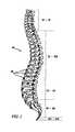
- the human spinal column 10is comprised of a series of thirty-three stacked vertebrae 12 divided into five regions.
- the cervical regionincludes seven vertebrae, known as C1-C7.
- the thoracic regionincludes twelve vertebrae, known as T1-T12.
- the lumbar regioncontains five vertebrae, known as L1-L5.
- the sacral regionis comprised of five vertebrae, known as S1-S5, while the coccygeal region contains four vertebrae, known as Co1-Co4.
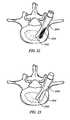
- FIG. 2depicts a superior plan view of a normal human lumbar vertebra 12 .
- human lumbar vertebraevary somewhat according to location, they share many common features.
- Each vertebra 12includes a vertebral body 14 .
- Two short bones, the pedicles 16extend backward from each side of the vertebral body 14 to form a vertebral arch 18 .
- each pedicle 16At the posterior end of each pedicle 16 , the vertebral arch 18 flares out into broad plates of bone known as the laminae 20 .
- the laminae 20fuse with each other to form a spinous process 22 .
- the spinous process 22serves for muscle and ligamentous attachment.
- a smooth transition from the pedicles 16 to the laminae 20is interrupted by the formation of a series of processes.
- Two transverse processes 24thrust out laterally on each side from the junction of the pedicle 16 with the lamina 20 .
- the transverse processes 24serve as levers for the attachment of muscles to the vertebrae 12 .
- Four articular processes, two superior 26 and two inferior 28also rise from the junctions of the pedicles 16 and the laminae 20 .
- the superior articular processes 26are sharp oval plates of bone rising upward on each side of the vertebrae, while the inferior processes 28 are oval plates of bone that jut downward on each side.
- the superior and inferior articular processes 26 and 28each have a natural bony structure known as a facet.
- the superior articular facet 30faces upward, while the inferior articular facet 31 (see FIG. 3 ) faces downward.
- the facets 30 and 31capped with a smooth articular cartilage, interlock to form a facet joint 32 , also known as a zygapophyseal joint.
- the facet joint 32is composed of a superior half and an inferior half.
- the superior halfis formed by the vertebral level below the joint 32
- the inferior halfis formed by the vertebral level above the joint 32 .
- the superior half of the joint 32is formed by bony structure on the L5 vertebra (i.e., a superior articular surface and supporting bone 26 on the L5 vertebra)
- the inferior half of the joint 32is formed by bony structure on the L4 vertebra (i.e., an inferior articular surface and supporting bone 28 on the L4 vertebra).
- An intervertebral disc 34 between each adjacent vertebrae 12permits gliding movement between the vertebrae 12 .
- the structure and alignment of the vertebrae 12thus permit a range of movement of the vertebrae 12 relative to each other.
- Back painparticularly in the “small of the back” or lumbosacral (L4-S1) region, is a common ailment. In many cases, the pain severely limits a person's functional ability and quality of life. Such pain can result from a variety of spinal pathologies.
- the laminae, spinous process, articular processes, or facets of one or more vertebral bodiescan become damaged, such that the vertebrae no longer articulate or properly align with each other. This can result in an undesired anatomy, loss of mobility, and pain or discomfort.
- the vertebral facet jointscan be damaged by either traumatic injury or by various disease processes. These disease processes include osteoarthritis, ankylosing spondylolysis, and degenerative spondylolisthesis.
- the damage to the facet jointsoften results in pressure on nerves, also called “pinched” nerves, or nerve compression or impingement. The result is pain, misaligned anatomy, and a corresponding loss of mobility. Pressure on nerves can also occur without facet joint pathology, e.g., a herniated disc.
- spinal stabilizationalso known as intervertebral stabilization.
- Intervertebral stabilizationprevents relative motion between the vertebrae. By preventing movement, pain can be reduced. Stabilization can be accomplished by various methods.
- One method of stabilizationis spinal fusion.
- Another method of stabilizationis fixation of any number of vertebrae to stabilize and prevent movement of the vertebrae.
- decompressive laminectomyThis procedure involves excision of the laminae to relieve compression of nerves.
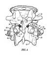
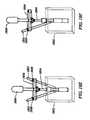
- FIG. 4shows an artificial cephalad and caudal facet joint prostheses 36 and 50 for replacing a natural facet joint.
- Cephalad joint prosthesis 36replaces the inferior half of a natural facet joint.
- Cephalad prosthesis 36has a bearing element 38 with a bearing surface 40 .
- Caudal joint prosthesis 50replaces the superior half of a natural facet joint.
- Caudal prosthesis 50has a bearing element 52 with a bearing surface 54 .
- Conventional fixation elements 56attach cephalad and caudal facet joint prostheses 36 and 50 to a vertebra in an orientation and position that places bearing surface 40 in approximately the same location as the natural facet joint surface the prosthesis replaces.
- the prosthesismay also be placed in a location other than the natural facet joint location.
- the spinal columnpermits the following types of movement: flexion, extension, lateral movement, circumduction and rotation.
- Each movement typerepresents relative movement between adjacent vertebra or groups of vertebrae.
- these relative movementsmay be simple movements of a single type but it is more likely that a single movement of the spine may result in several movement types or compound movement occurring contemporaneously. In the illustration of FIG. 4 , this translates into movement between the upper vertebral body 12 attached to the cephalad prosthesis 36 and the lower vertebral body 12 attached to caudal prosthesis 50 .
- the movement of the vertebral bodies 12can result in large, complex forces being generated and transmitted through the prosthesis.
- the point or points of contact between the bearing surface 40 of the cephalad prosthesis 36 and the bearing surface 54 of the caudal prosthesis 50can transmit enormous amounts of force onto both the cephalad and caudal facet joint prostheses 36 and 50 .
- the distance between each conventional fixation element 56 and the point or points of contactserves as a lever arm, thereby applying an enormous amount of axial, lateral and torque forces about each of the conventional fixation elements 56 , which act as fulcrums.
- cephalad prosthesis 36experiences a force somewhere on bearing surface 40 , which is expressed as axial, lateral and torque forces about the conventional fixation element 56 of the cephalad prosthesis 36 ; and likewise, caudal prosthesis 50 experiences a force somewhere on bearing surface 54 , which is expressed as axial, lateral and torque forces about the conventional fixation element 56 of the caudal prosthesis 50 .
- bearing surface 40which is expressed as axial, lateral and torque forces about the conventional fixation element 56 of the cephalad prosthesis 36
- caudal prosthesis 50experiences a force somewhere on bearing surface 54 , which is expressed as axial, lateral and torque forces about the conventional fixation element 56 of the caudal prosthesis 50 .
- the present inventionprovides prostheses, systems, and methods designed to replace natural facet joints and possibly part of the lamina at virtually all spinal levels including L1-L2, L2-L3, L3-L4, L4-L5, L5-S1, T11-T12, and T12-L1, using attachment mechanisms for securing the prostheses to the vertebrae.
- the prostheses, systems, and methodshelp establish a desired anatomy to a spine and return a desired range of mobility to an individual.
- the prostheses, systems, and methodsalso help lessen or alleviate spinal pain by relieving the source nerve compression or impingement.
- a natural facet jointsuch as facet joint 32 ( FIG. 3 )
- facet joint 32FIG. 3
- the superior half of the jointis formed by the vertebral level below the joint, which can thus be called the “caudal” portion of the facet joint because it is closer to the feet of the person.
- the inferior half of the facet jointis formed by the vertebral level above the joint, which can thus be called the “cephalad” portion of the facet joint because it is closer to the head of the person.
- a prosthesis that, in use, replaces the caudal portion of a natural facet jointi.e., the superior half
- a prosthesis that, in use, replaces the cephalad portion of a natural facet jointi.e., the inferior half
- a prosthesis that, in use, replaces the cephalad portion of a natural facet jointi.e., the inferior half
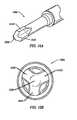
- a vertebral prosthesisin one aspect, includes a first bearing element and a first fixation element coupled to the first bearing element.
- the first bearing elementcan be shaped to form a facet joint with a second bearing element.
- the first fixation elementcan be inserted into a hole in a vertebra.
- the first fixation elementcan include an anti-rotation element.
- the anti-rotation elementcan be coupled to at least a portion of the vertebra. This portion of the vertebra can define the hole in the vertebra.
- the anti-rotation elementcan be adapted to resist a rotational force. With no resistance, the rotational force may cause rotation of the first fixation element within the hole in the vertebra.
- the hole in the vertebramay be just one hole. In other embodiments, there may be multiple holes in the vertebra. In the case of multiple holes in the vertebra, the first fixation element can be inserted into just one hole in the vertebra, or into multiple holes in the vertebra. Also in the case of multiple holes in the vertebra, the rotation force may cause rotation of the first fixation element within just one hole in the vertebra, or within multiple holes in the vertebra.
- the second bearing element with which the first bearing element forms a facet jointcan be part of a second prosthesis, or part of a natural vertebra. If the second bearing element is part of a second prosthesis, the second prosthesis can be one of the embodiments discussed herein, or another type of prosthesis.
- the fixation elementmay be secured directly into the vertebral body, or can be attached and/or “fixed” using a supplemental fixation material such as bone cement, allograft tissue, autograft tissue, adhesives, osteo-conductive materials, osteo-inductive materials and/or bone scaffolding materials.
- a supplemental fixation materialsuch as bone cement, allograft tissue, autograft tissue, adhesives, osteo-conductive materials, osteo-inductive materials and/or bone scaffolding materials.
- the first fixation elementcan be enhanced with a bony in-growth surface, such as surfaces created using sintering processes or chemical etching (Tecomet Corporation of Woburn, Mass.) which can help fix the fixation element within a vertebra.
- the bony in-growth surfacecan cover a portion or all of the first fixation element.
- a width of the prosthesismay be constant, or vary.
- a width of a proximal end of the first fixation elementcan exceed a width of a distal end of the first fixation element.
- a width of a proximal end of the anti-rotation elementcan exceed a width of a distal end of the anti-rotation element.
- a width of a distal end of the first fixation elementcan exceed a width of a proximal end of the first fixation element.
- the anti-rotation elementcan be coupled to the vertebra by being directly connected to the vertebra.
- the anti-rotation elementalso can be coupled with at least cement to the vertebra.
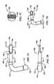
- the anti-rotation elementincludes a wing.
- the wingcan be positioned at a proximal of distal portion of the first fixation element. When the first fixation element is inserted into a first hole or holes in the vertebra, the wing can be inserted into a second hole of the vertebra.
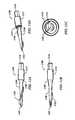
- the anti-rotation elementincludes a blade.
- the bladecan be positioned at a proximal or distal portion of the first fixation element. When the first fixation element is inserted into a first hole or holes in the vertebra, the blade can also be inserted into the first hole in the vertebra.
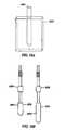
- the anti-rotation elementincludes a paddle.
- the paddlescan be positioned at a distal or proximal portion of the first fixation element.
- the first fixation elementcan be straight, or include one or more bends.
- the anti-rotation elementcan include one or more grooves positioned distally and/or proximally from the paddle.
- the anti-rotation elementcan also include other features, such as one or more wings positioned proximally or distally from the paddle, and/or one or more blades positioned proximally or distally from the paddle.
- the anti-rotation elementincludes an intersection of three or more projections.
- the intersectioncan be positioned at a distal or proximal portion of the first fixation element.
- the anti-rotation elementincludes a helical projection.
- the anti-rotation elementcan include an intersection of two or more helical projections.
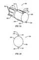
- the anti-rotation elementincludes a longitudinal depression.
- the longitudinal depressioncan have a longitudinally varying profile.
- the longitudinal depressionscan be a helical longitudinal depression, a groove, or a flute.
- the longitudinal depressioncan help define a spline.
- the anti-rotation elementmay further include a perimeter (circumferential) depression.
- the perimeter depressioncan be a perimeter undercut.
- the anti-rotation elementcan include separated members.
- the first fixation elementcan include a longitudinal hole.
- a filling elementcan be inserted into the longitudinal hole and spread the separated members of the anti-rotation element.
- the separated memberscan be positioned at a distal portion of the first fixation element.
- the anti-rotation elementcan define a hole, into which the first fixation element is inserted.
- the first fixation elementcan define a hole into which the anti-rotation element is inserted.
- the holecan be tapered (using, for example, a tapered broach) and/or the first fixation element can have a taper.
- the anti-rotation elementcan have a taper.
- the anti-rotation elementcan be coupled to the first fixation element by an interference fit.
- the anti-rotation elementcan include a bend, or be straight.
- the first fixation elementcan be straight, or include a bend.
- the anti-rotation elementincludes one or more proximal projections.
- a vertebral prosthesisin another aspect, includes a first bearing element and a first fixation element.
- the first bearing elementcan be shaped to form a facet joint with a second bearing element.
- the first fixation elementcan be coupled to the first bearing element.
- the first fixation elementcan be inserted into a hole in the vertebra.
- the first fixation elementcan be shaped to resist a rotational force. With no resistance, the rotational force may cause rotation of the first fixation element within the hole in the vertebra.
- the second bearing element with which the first bearing element forms a facet jointcan be part of a second prosthesis, or part of a natural vertebra. If the second bearing element is part of a second prosthesis, the second prosthesis can be one of the embodiments discussed herein, or another type of prosthesis.
- the first fixation elementcan be enhanced with a bony in-growth surface, which can help fix the fixation element within a vertebra.
- the bony in-growth surfacecan cover a portion or the entire first fixation element.
- a width of the prosthesismay be constant, or vary.
- a width of a proximal end of the first fixation elementcan exceed a width of a distal end of the first fixation element.
- a width of a proximal end of the anti-rotation elementcan exceed a width of a distal end of the anti-rotation element.
- the width of a distal end of the anti-rotation elementcan exceed a width of a proximal end of the anti-rotation element.
- the anti-rotation elementcan be coupled to the vertebra by being directly connected to the vertebra.
- the anti-rotation elementalso can be coupled with at least cement to the vertebra.
- the first fixation elementcan be shaped with a bend.
- the first fixation elementcan have a taper.
- a vertebral prosthesis methodin another aspect, includes coupling a first bearing element to a first fixation element, coupling an anti-rotation element to the first fixation element (as a feature of the component or as a separate component), and inserting the first fixation element into a hole in the vertebra.
- the first bearing elementcan be shaped to form a facet joint with a second bearing element.
- the anti-rotation elementcan be adapted to resist a rotational force. With no resistance, the rotational force may cause rotation of the first fixation element within the hole in the vertebra.
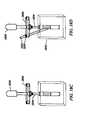
- a vertebral prosthesis preparation methodincludes perforating a vertebra with at least a first hole, supporting a perforation guide with a guide support, guiding a perforation tool with the perforation guide, and perforating the vertebra with a second hole (or shaped cavity) aligned by the perforation guide.
- the first holecan be shaped to receive a prosthetic fixation element.
- the guide supportcan be positioned by a portion of the vertebra defining a hole.
- the second holecan be shaped to receive a first prosthetic anti-rotation element.
- the methodcan include the step of using the perforation tool while at least partly removing the guide support.
- Various embodimentsinclude the step of perforating the vertebra with a third hole aligned by the perforation guide.
- the third holecan be shaped to receive a second prosthetic anti-rotation element.
- the methodcan include the step of using the perforation tool while least partly removing the guide support.
- the guide supportcan be inserted while perforating the vertebra with the first hole.
- the guide supportcan be inserted after perforating the vertebra with the first hole.
- a vertebral prosthesis toolin yet another aspect, includes a guide support and a perforation guide.
- the guide supportcan be stabilized by a first hole of the vertebra.
- the first holecan be shaped to receive a prosthetic fixation element of the vertebral prosthesis.
- the vertebral prosthesiscan form a facet joint with a second vertebral prosthesis.
- the perforation guidecan be coupled to the guide support.
- the perforation guidecan guide a perforation tool to perforate the vertebra with a second hole aligned by the perforation guide.
- the second holecan be shaped to receive a prosthetic anti-rotation element of the vertebral prosthesis.
- FIG. 1is a lateral elevation view of a normal human spinal column
- FIG. 2is a superior plan view of a normal human lumbar vertebra
- FIG. 3is a lateral elevation view of adjoining normal human lumbar vertebrae L4 and L5;
- FIG. 4is a perspective view of a cephalad prosthesis for replacing the inferior half of a natural facet joint on a superior vertebral body;
- FIGS. 5A and 5Bprovide a perspective and proximal sectional view, respectively, of a vertebral prosthesis portion with blades;
- FIGS. 6A , 6 B, and 6 Cprovide a side elevation view, another side elevation view, and a perspective view, respectively, of a vertebral prosthesis portion with a paddle;
- FIGS. 7A , 7 B, 7 C, and 7 Dprovide a side elevation view, plan view, distal sectional view, and perspective view, respectively, of a vertebral prosthesis portion with a fixation element having a bend and a paddle;
- FIGS. 8A , 8 B, and 8 Cprovide a side elevation view, plan view, and perspective view, respectively, of a vertebral prosthesis portion with a fixation element having a bend, a paddle, and additional distally located anti-rotation elements;
- FIGS. 9A and 9Bprovide a perspective views of a vertebral prosthesis portion with a paddle, straight fixation element, and additional anti-rotation elements;
- FIGS. 10A and 10Bprovide a perspective view and a distal end view, respectively, of a vertebral prosthesis portion with an intersection of multiple projections;
- FIGS. 11A , 11 B, 11 C, and 11 Dprovide a side view, a perspective view, another side view, and a distal end view, respectively, of a vertebral prosthesis portion with a helical projection;
- FIGS. 12A and 12Bprovide a perspective view and a distal end view, respectively, of a vertebral prosthesis portion with two helical projections
- FIGS. 13A and 13Bprovide a perspective view and a distal end view, respectively, of a vertebral prosthesis portion with longitudinal depressions;
- FIGS. 14A and 14Bprovide a perspective view and a distal end view, respectively, of a vertebral prosthesis portion with helical longitudinal depressions and a fixation element with a bend;
- FIG. 14Cprovides a perspective view of a pair of vertebral prosthesis, as in FIGS. 14A and 14B , connected by a cross-bar member;
- FIGS. 15A , 15 B, 15 C, and 15 Dprovide, a side view, an isometric view and a distal end view, a sectional view taken along the line shown in the distal end view FIG. 15C respectively, of a vertebral prosthesis portion with tapered longitudinal depressions and perimeter depressions;
- FIGS. 16A and 16Bprovides a perspective view of a vertebral prosthesis portion with separated members
- FIGS. 17A , 17 B, and 17 Cprovide a perspective view, a side view, and a distal end view, respectively, of a vertebral prosthesis portion with wings;
- FIGS. 18A through 18Fillustrate different steps in a vertebral prosthesis method for the vertebral prosthesis of FIGS. 17A through 17C ;
- FIG. 19is a close up view of the vertebral prosthesis tool used in the method of FIGS. 18A through 18F ;
- FIGS. 20A and 20Bshow a perspective view and a close-up view, respectively, of a vertebral prosthesis tool for a vertebral prosthesis with proximal anti-rotation features;
- FIGS. 21A and 21Bshow a vertebral prosthesis portion with proximal projections, and the insertion of the prosthesis portion into a vertebra following the vertebral prosthesis tool of FIGS. 20A and 20B , respectively;
- FIG. 22is a perspective view of an installed vertebral prosthesis according to an embodiment of the invention where a fixation element is inserted into anti-rotation element;
- FIG. 23is a perspective view of an installed vertebral prosthesis according to another embodiment of the invention where a fixation element is inserted into anti-rotation element;
- FIG. 24is a perspective view of a vertebral prosthesis portion shaped to resist rotational force.
- Embodiments of the present inventionmay be used, with advantage, on a wide variety of prosthesis devices, particularly spinal prostheses.
- Some of these prostheses, systems, and methodsare discussed in the following applications entitled: “Facet Arthroplasty Devices And Methods”, by Mark A. Reiley, Ser. No. 09/693,272, filed Oct. 20, 2000, now U.S. Pat. No. 6,610,091, issued Aug. 26, 2003; “Prostheses, Tools And Methods For Replacement Of Natural Facet Joints With Artificial Facet Joint”, by Lawrence Jones et al., Ser. No. 10/438,295, filed May 14, 2003; “Prostheses, Tools And Methods for Replacement Of Natural Facet Joints With Artificial Facet Joint”, by Lawrence Jones et al., Ser.
- FIGS. 5A and 5Bshow one embodiment of a vertebral prosthesis portion 500 with proximally positioned blades 504 that function as anti-rotation elements.
- the vertebral prosthesis portion 500has a proximal portion 502 with a pair of blades 504 .
- the two blades 504are positioned on opposite sides of the perimeter of the vertebral prosthesis portion 500 , and are thus positioned apart by about 180 degrees.
- a grooved portion 505having grooves 506 along the periphery of the vertebral prosthesis portion 500 .
- the illustrated grooved portion 505has grooves 506 that taper in a proximal direction along the vertebral prosthesis portion 500 .
- Other groove configurationsas possible, for example, see FIGS.
- a transition section 525separates the proximal portion 502 from the grooved portion 505 . While the illustrated transition section 525 has a uniform, linear transition from the diameter of the proximal portion 502 to the grooved portion 505 , other transition sections are possible depending upon the relative geometry of the grooved portion 505 and the proximal portion 502 . In one embodiment, the transition section 525 can serve as a cement restrictor, preventing and/or inhibiting cement flow out of the vertebral body. In some embodiments, a transition section 525 may not be used.
- Alternative embodiments of the vertebral prosthesis portion 500may have one blade, three blades, or more blades. Alternative embodiments can also employ a different amount of spacing other than 180 degrees between multiple blades for embodiments with multiple blades, and the spacing can be the same or different between the multiple blades. While the embodiment illustrated in FIGS. 5A and 5B illustrates blades 504 separated by convex portions 520 , other configurations are possible. For example, the blades 504 may be separated by concave sections as illustrated, for example, in FIG. 15D or in combinations of convex and concave portions.
- blades 504have pointed triangular profiles, alternative embodiments can have rounded points, no points, and/or other profiles of other geometries, such as square, rectangular, trapezoidal, arcuate, etc and combinations thereof.
- blades 504have a uniform incline section 514 and decline section 516 and a single height ridge 518 .
- Other configurationsare possible.
- the incline and decline sections 514 , 516may be different as in, for example, FIGS. 17A , 17 B and 17 C.
- the blades 504are sufficiently small such that the blades 504 can fit into the same vertebral hole that receives the fixation element.
- proximal anti-rotation elements of vertebral prosthesis portion 500may be used in combination with other vertebral prosthesis portions described below.
- advantages of the proximal anti-rotation features of vertebral prosthesis portion 500may be combined with conventional prosthesis fasteners resulting in a hybrid prosthesis fastener having a conventional distal portion and a proximal portion having anti-rotations feature or features of the vertebral prosthesis portion 500 .
- FIGS. 6A , 6 B, and 6 Cshow an embodiment of a vertebral prosthesis portion 600 with a paddle 604 and grooves as an anti-rotation element. While desiring not to be bound by theory, it is believed that the wide surface area(s) provided by the anti-rotational paddle embodiments of the present invention provide greater resistance to the torque loads applied to the prosthesis and attempted rotation of the paddle within the vertebra. For example, the additional of surface projections and/or pits can significantly increase the total surface are of the prosthesis, thereby increasing the ability of any adhesion between the prosthesis and the surrounding material (such as bone cement, epoxy or in-growing bony material) to secure the prosthesis in position.
- the surrounding materialsuch as bone cement, epoxy or in-growing bony material
- the additional of surface projections and pitscan interact with the surrounding material to create a geometric or mechanical “interlock” that resists relative motion between the prosthesis and the surrounding material.
- the paddle embodiments of the present invention described hereinact as improved anti-rotational elements.
- other anti-rotation elements described hereinare also used to counteract the torque loads developed within and acting upon various portions of vertebral prosthesis.
- the vertebral prosthesis portion 600has a distal end 601 and a proximal end 602 .
- the proximal end 602is configured to accept tooling and instruments to secure the vertebral prosthesis portion 600 into the vertebra and/or to provide an attachment point to another vertebral prosthesis component.
- a distal portion of a fixation elementhas a paddle 604 configured to act as an anti-rotation element to prevent the rotation of the vertebral prosthesis portion 600 once implanted into a vertebra.
- Alternative embodiments of the vertebral prosthesis portion 600can have multiple paddles.
- the illustrated paddle 604has a rounded profile, alternative embodiments may have different profiles including, for example, one or more corners.
- the illustrated paddle 604is flat, alternative embodiments can have nonflat contours, with one or more concave and/or convex features.
- FIGS. 6A , 6 B, and 6 Calso illustrate an embodiment of an anti-pull out feature of the vertebral prosthesis portion 600 .
- Embodiments of the vertebral prosthesis portion 600also include anti-pull out features.
- an anti-pull out featurerefers to an element or combination of elements of a prosthesis portion or fastener acting to mitigate, minimize or counteract forces bearing upon the prosthesis portion or fastener to disengage, loosen, advance, pull or otherwise axially translate the fastener relative to a desired position on or within the vertebra.
- the vertebral prosthesis portion 600includes a proximal grooved portion 605 having proximal grooves 606 and a distal grooved portion 615 having distal grooves 617 .
- proximal grooves 606have a proximal tip with a width that increases distally and distal grooves 617 have a nearly constant width terminating in a distal tip.
- a reduced diameter portion 608separates the proximal grooved portion 605 from the distal grooved portion 615 .
- the proximal grooves 606 , distal grooves 617 and reduced diameter section 608act to increase the surface area of the vertebral prosthesis portion 600 .
- By increasing the surface area of the vertebral prosthesis portion 600provides greater attachment between the vertebral prosthesis portion 600 and the vertebra.
- the greater amount of surface areamay be used advantageously with bone cement, bone growth compounds or other materials used to bond the external surfaces the vertebral prosthesis portion 600 to the interior of the vertebra.
- the greater surface areaallows, in embodiments where bone fixation cement is used, more cement to be present along the length and a particularly greater amount of cement or fixation material to be present about the reduced diameter section 608 .
- the increased amount of cement present adjacent the reduced diameter portion 608produces a section of increased diameter that counteracts pull out forces.
- Other configurations, arrangements and geometries of the proximal grooved portion 605 , reduced diameter portion 608 , and distal grooved portion 615are possible.
- different groove configurationsare possible (e.g., FIGS. 9A , 13 A and 15 F), there may be multiple distal or proximate grooved portions (e.g., FIG. 15B ), multiple reduced diameter portions (e.g., FIG. 15B ) or different paddle configurations (e.g., FIGS. 7A-7D and FIGS. 8A-8C ).
- FIGS. 7A , 7 B, 7 C, and 7 Dshow an embodiment of a vertebral prosthesis portion 700 with a fixation element having a bend 710 , and a paddle 704 as an anti-rotation element, similar to the vertebral prosthesis portion shown in FIGS. 6A , 6 B, and 6 C.
- the vertebral prosthesis portion 700includes a distal end 701 and a proximal end 703 .
- the proximal end 703includes a bearing element 715 for engagement to other portions of the vertebral prosthesis.
- the fixation elementincludes a bend 710 connected to a shaft 735 having a paddle 704 attached thereto.
- the vertebral prosthesis portion 700also illustrates an embodiment of a modular prosthesis fastener concept.
- the shaft 735is detachably fastened to the attachment point 740 .
- the shaft 735has a length “l” between the attachment point 740 and the proximate end of the paddle 704 .
- the shaft 735is detachably coupled to the attachment point 740 to allow for shafts 735 of different lengths to be used with different configurations of the vertebral prosthesis portion 700 thereby providing a modular vertebral prosthesis.
- the shaft 735may be detached from the attachment point 740 and replaced with a shaft 735 having a different length “l” as needed until the proper alignment of the vertebral prosthesis is achieved.
- Modular componentscan be attached to the prosthesis using one or more attachments methods well known in the art, including threaded screws, morse tapers, adhesives or set screws.
- the shaft 735may be of fixed length and permanently attached to the attachment point 740 while the detachable attachment point is positioned between the shaft 735 and the paddle 704 thereby allowing paddles 704 of different lengths to be used.
- both the shaft and the paddlemay have detachable attachment points thereby allowing various shaft lengths and configurations and paddle lengths and configurations to be used in furtherance of the modular vertebral prosthesis concepts described herein.
- the detachable attachment pointmay be positioned between any portion or portions of the embodiments of the vertebral prosthesis portions described herein and elsewhere in this patent application.
- one or more sections of the vertebral prosthesismay be made of a deformable or shape-memory material (such as Nitinol or similar materials), which permits the physician to make adjustments to the prosthesis geometry to “form-fit” the implant to the patient's specific anatomy.
- a deformable or shape-memory materialsuch as Nitinol or similar materials
- the materialcan be heated or cooled away from the body temperature (depending upon the type of material and it's martensitic/austenitic properties), be deformed to a desired shaped, and then held in the deformed position and allowed to return to the body temperature, thereby “hardening” into the desired shape or form.
- Such an embodimentwould facilitate a reduction in the number of sections or “modules” required for a modular prosthesis, as each module could assume a variety of desired positions.
- the angle of the illustrated bend 710is acute, other embodiments of the vertebral prosthesis portion 700 can have bend 710 having a right angle or an obtuse angle.
- Alternative embodiments of the vertebral prosthesis portion 700may include two, three, or more bends 710 .
- the paddle 704has a flat surface 720 and a proximal end having a transition portion 730 .
- the flat surface 720is illustrated in the same plane in which the fixation element has the bend 710 .
- the paddle 704has a flat surface 720 in another plane, and/or a nonflat contour, with one or more concave and/or convex features or have paddle shapes similar to the distal portions illustrated in FIGS.
- the transition portion 730has a width that decreases linearly in a proximal direction.
- Other configurations of the transition portion 730are possible for transitioning from the paddle 704 to the shaft 735 of the vertebral prosthesis portion 700 .
- the alternative shapes of the transition portioninclude, for example, a non-linear decreasing proximal width, asymmetric portions, curved portions or compound portions.
- FIGS. 8A , 8 B, and 8 Cshow an embodiment of a vertebral prosthesis portion 800 with a fixation element having a bend 810 , and compound anti-rotational elements included in the paddle 804 .
- a proximal socket element 807is attached to the bend 810 by a proximal shaft 850 .
- a distal shaft 860couples the bend 810 to the paddle 804 . While the illustrated bend 810 has only a single, acute angle, it is to be appreciated that in other embodiments the bend 810 may have a have a right angle or an obtuse angle and may include two, three, or more bends.
- one or more detachable connectionsmay exist between the various elements of the vertebral prosthesis portion 800 .
- elements of different lengthse.g., shafts 850 , 860
- sizee.g., socket 807 and paddle 804
- angular orientatione.g., bend 810 , paddle 804
- Embodiments of the vertebral prosthesis portion 800may have paddle 804 embodiments similar to the paddle embodiments shown and described with regard to vertebral prosthesis portion 700 (see e.g., FIGS. 7A , 7 B, 7 C, and 7 D).
- the paddle 804may include a flat face similar to face 720 described above, however, other configurations are possible.
- paddle 804has a non-flat face 820 that may be convex, concave or have portions that are combinations of convex, concave or flat.
- the paddle surface 820may be a flat surface in another plane, and/or a nonflat contour, with one or more concave and/or convex features.
- the paddle surface 820is in the same plane in as the bend 810 . In other embodiments, the paddle surface(s) 820 may not be in plane with the bend 810 .
- embodiments of the paddle 804also include compound or more than one anti-rotation elements. As discussed above, the paddle surfaces generally provide an anti-rotation or rotation-resistant component to the vertebral prosthesis. Additionally, embodiments of paddle 804 include other anti-rotational elements such as the enlarged distal tip 812 having grooves 815 and projections 819 . The enlarged distal tip 812 may have one or more grooves 815 positioned distally from the paddle 804 . In some embodiments, the grooves occur in the same plane as the plane of the paddle 804 . In other embodiments, grooves can occur in multiple planes and/or planes that are different from the plane of the paddle 804 .
- the distal tipmay have projections 819 in the same or different plane with the faces of paddle 804 . While the illustrated projections 819 appear identical in shape and size and are arranged parallel to the axis of the proximal shaft 860 , it is to be appreciated that the projections 819 may have different configurations. The projections 819 may not all be the same size or have the same overall shape, have an asymmetrical orientation relative to the paddle 804 or be positioned in a non-parallel arrangement with regard to the axis of the proximal shaft 860 .
- FIGS. 9A and 9Billustrate an alternative embodiment of a vertebral prosthesis portion having anti-rotation and anti-pullout elements.
- the paddle 955 and proximal ridges 925 , 927act as anti-rotation elements.
- the reduced diameter section 940 , grooved sections 930 , 945 and reduced shank diameter 920 , 922act as anti-pullout elements.
- the vertebral prosthesis portions 900 and 990are similar in many regards to vertebral prosthesis portion 600 if FIGS. 6A , 6 B and 6 C. However, several differences are important.
- Paddle 955has a flat face 960 but a rounded, tapered distal end 965 instead of a flat distal edge found on paddle 604 (see FIG. 6B ).
- Proximal grooves 935have a constant width instead of a tapered width (see FIG. 6A grooves 606 ).
- Distal grooves 950have a uniform width and a rounded distal end instead of a distal tip (grooves 617 of FIG. 6B ).
- the proximal anti-rotation sections 920 , 922include a shank having a diameter less than the shank 915 and a plurality (two in the illustrated embodiments) of ridges that act as proximal anti-rotation elements.
- Vertebral prosthesis portion 900has a proximal anti-rotation portion 920 and ridges 925 having an overall height h 1 .
- Vertebral prosthesis portion 990has a proximal anti-rotation portion 922 and ridges 927 having an overall height h 2
- ridges 927having an overall height h 2
- the ridgescan desirably engage surrounding cortical bone at the pedicle entry point, which is often stronger than the cancellous bone contained within the vertebral body, although the ridges' engagement with either or both types of bone will serve to resist rotation to varying degrees).
- the height h 1is 8.25 mm and the proximal anti-rotation section diameter is 6.5 mm but still maintains a moment of inertia (I y ) equal to that of a 7 mm rod.
- the overall ridge height h 2is 8.75 mm and the proximal anti-rotation section diameter is 6.0 mm but the embodiment still maintains a moment of inertia (I y ) equal to that of a 7 mm rod.
- vertebral prosthesis portions 900 and 990may differ from the illustrated embodiments.
- the additional ridgesneed not have uniform cross sections or be uniformly spaced about the perimeter of the proximal anti-rotation section.
- the paddle face 960may have a different face such as convex, concave or other compound shape or combinations thereof.
- FIGS. 10A and 10Bshow an embodiment of a vertebral prosthesis portion 1000 with an intersection of multiple projections as an anti-rotation element.
- the distal portion of the fixation elementhas three projections 1018 .
- the three projections 1018meet at an intersection 1020 of the projections.
- the three projections 1018meet at the center, as viewed from the distal end.
- multiple projectionscan meet at an off-center position as viewed from the distal end.
- the three projections 1018are positioned equidistantly about the perimeter of the fixation element, and are thus positioned apart by about 120 degrees.
- Alternative embodimentscan have one projection, two projections, four projections, or more projections.
- Alternative embodimentscan also employ a different amount of spacing other than 120 degrees between multiple projections, and the spacing can be the same or different between the multiple projections.
- the illustrated projections 1018have a trapezoidal profile as viewed from the side of the prosthesis portion, alternative embodiments can have other profiles of other geometries, such as square, rectangular, triangular, etc.
- FIGS. 11A , 11 B, 11 C and 11 Dillustrate another embodiment of a vertebrae prosthesis portion having a helical projection that acts as an anti-rotation element.
- FIGS. 11A , 11 Bare right and left side views of a vertebral prosthesis portion 1100 .
- the vertebral prosthesis portion 1100has a distal tip 1105 and a proximal fitting 1110 .
- the proximal fitting 1110is attached to a shank 1115 and a tapered shaft 1120 .
- a single step transition section 1130is used to change diameters from the shank 1115 to the proximal end of the tapered shaft 1120 .
- a rounded profile ridge 1122spirals proximally from the distal tip 1105 to the transition section 1130 .
- the illustrated embodimentshows the ridge 1122 beginning at the distant tip 1105 and spiraling continuously to the transition section 1130
- the ridgebegins at a position proximate to the distal tip 1105 or ends distal to the transition section 1130 .
- the ridge 1122need not be continuous but may be segmented into a plurality of sections have the same or different lengths. (If desired, the interrupted ridge could additionally act as a “self-locking” feature to resist undesired removal of the prosthesis.)
- the ridge 1122need not be of uniform height but may have various heights that increase or decrease in a proximal direction or alternate such as in a sinusoidal pattern. FIG.
- the ridge 1122has a pitch of about one revolution meaning that as the ridge 1122 spirals along the tapered shaft 1120 it traces a path that traverses a single rotation absent the tapered shaft.
- the ridge 1122may traverse the tapered shaft 1122 at an increased pitch (more than one revolution) or a decreased pitch (less than one revolution, see e.g. FIG. 11D ).
- the ridge 1122may have other cross-sectioned shapes other than rounded such as, for example, a sharp edge or triangular cross section as in FIG. 11D .
- Vertebral prosthesis portion 1150illustrates and alternative embodiment of the helical ridge anti-rotation element ( FIG. 11D ).
- Vertebral prosthesis portion 1150is similar in many respects to vertebral prosthesis portion 1100 and similar reference numbers have been used for like components.
- Vertebral prosthesis portion 1150has a multiple step transition section 1155 between the shank 1115 and the tapered shaft 1160 .
- the tapered shaft 1160has a more gradual taper than the taper in tapered shaft 1120 .
- the ridge 1170has a sharp edge and a pitch of less than one revolution. Desirably, the transition in the shaft will reduce and/or eliminate the stress concentration or “stress riser” inherent in the diameter transition.
- a vertebral prosthesis portion 1200may have more than one ridge anti-rotation element ( FIGS. 12A , 12 B).
- the vertebral prosthesis portion 1200has a distal tip 1205 and a proximal end 1210 .
- a shank 1215is attached to the proximal end 1210 and a stepped transition section 1255 .
- a tapered shaft 1260extends from the stepped transition section 1255 to the distal tip 1205 .
- Two ridges 1222 , 1224project outwardly from the tapered shaft 1260 .
- the upper ridge 1222has a rounded top surface and is wider than the lower ridge 1224 that is narrower with a more pronounced or sharper ridge top surface.
- ridges 1222 , 1224have the same pitch of less than one revolution. It is to be appreciated that the ridges 1222 , 1224 could have a pitch greater than one or each ridge could have a different pitch or more than two ridges could traverse tapered shaft 1260 .
- Other alternative ridge configurations as described above with regard to ridges 1122 and 1170are applicable to ridges 1222 , 1224 .
- the ridges 1222 , 1224project from opposite sides of the tapered shaft 1260 and are evenly spaced apart by a separation angle of about 180 degrees.
- Alternative embodimentscan have three ridge or helical projections, four helical projections, or more helical projections.
- Alternative embodiments and the illustrated embodimentmay also employ a separation angle or angles of other than 180 degrees between helical projections and the spacing can be uniform between all projections or be variable and/or different between projections.
- the ridges or helical projectionsmay begin at a location on the tapered shaft 1260 proximal to the distal tip 1205 and may end distal to the stepped transition section 1255 .
- FIGS. 13A and 13Billustrate an embodiment of a vertebral prosthesis portion 1300 have longitudinal grooves as anti-rotation elements.
- the vertebral prosthesis portion 1300has a distal end 1305 and a proximate end 1310 attached to a shank 1320 .
- a transition section 1325separates the shank 1320 from the proximal grooved section 1330 having grooves 1335 formed therein.
- a reduced diameter section 1340separates the proximal grooved section 1330 from the distal grooved section 1345 .
- the distal grooved section 1345has grooves 1350 formed therein. As can be seen more clearly in distal end view of FIG. 13B , there are four grooves 1350 in the illustrated embodiment.
- the groove configuration of vertebral prosthesis portion 1300differs from earlier described grooves 506 ( FIG. 5A ), grooves 945 , grooves 935 ( FIGS. 9A , 9 B) in a number of ways.
- the grooves 1350are much wider and there are fewer of them than in previous embodiments.
- the grooves 1350are wider distally and taper proximally to the reduced diameter section 1340 .
- the grooves 1350are evenly spaced about the distal grooved section 1345 and have the same rounded cross section (see FIG. 13B ). However, in alternative embodiments, the grooves 1350 have different spacings and different cross-sectioned shapes.
- each of the longitudinal grooves or depressions 1350has a longitudinally varying profile, narrowing as the groove extends proximally.
- the longitudinally varying profilecan widen or remain constant as the longitudinal depression or groove extends proximally (if desired, they can change in depth as they narrow in width).
- all of the longitudinal depressions or grooves 1350are identical, in other embodiments, the multiple longitudinal depressions can differ, for example by having different profiles, lengths, starting and/or ending points, etc.
- Alternative embodimentscan have one longitudinal depression, two longitudinal depressions, three longitudinal depressions, five longitudinal depressions, or more longitudinal depressions.
- Alternative embodimentscan also employ a different amount of spacing other than 90 degrees between multiple longitudinal depressions for embodiments with multiple longitudinal depressions, and the spacing can be the same or different between the longitudinal depressions.
- the proximal grooved section 1330has fewer grooves 1335 than previously described proximal grooved sections (e.g. FIGS. 5A , 9 A and 9 B). There are two grooves 1335 in the proximal grooved section 1330 , although only one is visible in FIG. 13A . Grooves 1335 align with a distal groove 1350 in the illustrated embodiment. The grooves 1335 have a groove profile that is wider distally and tapering proximally to a tip at transition section 1325 . It is to be appreciated that alternative embodiments may have one or more grooves 1335 to align one for one with grooves 1350 .
- grooves 1335there may be the same number of grooves 1335 as grooves 1350 however, grooves 1335 may be offset radically so as not to align axially with grooves 1350 as illustrated. Both grooves 1350 , 1335 need not be parallel to the longitudinal axis if the vertebral prosthesis portion 1300 but may instead be arranged in non-parallel configurations with respect to the longitudinal axis of the vertebral prosthesis portion 1300 .
- FIGS. 14A and 14Bshow an embodiment of a vertebral prosthesis portion 1400 with helical longitudinal depressions as anti-rotation elements and a fixation element with a bend.
- the illustrated embodiment of the vertebral prosthesis portion 1400has a distal tip 1404 and a proximal end 1402 .
- the proximal end 1402includes a socket element 1407 for further attachment to a vertebral prosthesis.
- the element 1407could comprise a bearing surface for slidably engaging a corresponding bearing surface (not shown) of a caudal portion of a vertebral prosthesis).
- Proximal shaft 1415is attached to the socket element 1407 and the bend 1410 .
- the tapered section 1430transitions from the proximal shaft 1415 to the distal shaft 1417 [as the proximal shaft 1415 is a different diameter than the distal shaft 1417 .] Other transitions are possible such as a stepped transition (e.g. section 740 of FIG. 7B ) or no transition if the diameter of the shafts 1415 and 1417 are the same.
- the distal shaft 1417includes a plurality of longitudinal depressions 1423 extending from the distal end 1404 to a point beyond the tapered section 1430 .
- the proximal end of the longitudinal depressions 1423has a bulbed section 1460 .
- the distal shaft 1417also includes a reduced diameter section 1440 .
- the reduced diameter section 1440 , longitudinal grooves 1423 and bulbed section 1460may be used to increase the surface area of the vertebral prosthesis portion 1440 that is, when implanted, within a vertebra of the spine.
- the increased surface areaallows for more area to support the cement mantle for applications using cement or, bony ingrowth for applications using bone ingrowth.
- longitudinal grooves 1423may also be varied as described elsewhere with regard to other grooves and, for example, as described with regard to FIGS. 13A , 13 B, 6 A, 6 B, 6 C and 5 A.
- alternative embodiments of bend 1410are possible as described with regard to FIGS. 7A-7D and 8 A- 8 C.
- each of the longitudinal depressions 1423has a longitudinally varying profile, narrowing as the longitudinal depression extends proximally.
- the longitudinally varying profilecan widen or remain constant as the longitudinal depression extends proximally.
- the multiple longitudinal depressionscan differ, for example by having different profiles, lengths, starting and/or ending points, etc.
- Alternative embodimentscan have one longitudinal depression, two longitudinal depressions, four longitudinal depressions, five longitudinal depressions, or more longitudinal depressions.
- FIG. 14Cdepicts an alternate embodiment of the vertebral prosthesis of FIGS. 14A , 14 B in which a pair of prosthesis 1400 are connected by a cross-bar 1405 .
- Cross-bar 1405can be a cylindrical member fitting into openings 1409 in each of the shafts 1415 of the prosthesis 1400 (or can be virtually any rigid or semi-rigid member secured between the two prosthesis), and the cross-bar 1405 desirably reduces or prevents rotation of the prosthesis 1400 relative to each other.
- any torsional loads experienced by an individual prosthesis 1400will be transferred to the shaft 1415 of the opposing prosthesis by the cross-bar 1405 , which will convert the torsional load to a transverse load acting on the opposing prosthesis.
- the newly loaded prosthesiscan resist this transverse force, thereby maintaining the entire structure in a desired position.
- the cross-bartherefore “shares” and redistributes the torsional loading experienced by an individual prosthesis, significantly reducing the tendency for an individual prosthesis to rotate.
- FIGS. 15A-15Dillustrate a vertebral prosthesis portion 1500 having a plurality of grooved portions and reduced diameter portions as anti-rotation elements and anti-pullout elements.
- the vertebral prosthesis portion 1500includes a proximal end 1505 and a distal end 1510 .
- a shank 1515is connected to the proximal end 1505 .
- a diameter transition section 1520is used to step down the diameter from the shank 1515 to the distal grooved section.
- the transition section 1520desirably limits or eliminates potential stress concentrations or “risers” which can occur due to this geometry change.
- the transition section 1520desirably will form a tight fit with the opening formed in the bone, sealing the opening (not shown) and facilitating pressurization of cement or other supplemental fixation material within the bone without cement exiting the opening—thereby ensuring the prosthesis is well-anchored in the fixation material, if used.
- the vertebrae prosthesis portion 1500includes three grooved sections: the proximal grooved section 1525 having proximal grooves 1530 , the middle grooved section 1540 having middle grooves 1545 and the distal grooved section having distal grooves 1560 .
- the grooves 1530 , 1545 and 1560are of similar size, shape and orientation.
- the grooveshave a rounded cross section profile best seen in FIG. 15D and pronounced or sharp ridges 1565 between adjacent grooves.
- middle grooves 1545 and proximal grooves 1530have a tapered width that decreases proximally.
- Other groove and reduced diameter configurations, cross section profile and angular orientationsare possible and are described above with regard to other grooves and reduced diameter portions in other embodiments as well as described with regard to FIGS. 6A , 6 B, 6 C, 14 A, 14 B, 13 A, 13 B, 9 A and 9 B.
- FIGS. 16A and 16Bshow an embodiment of a vertebral prosthesis fixation element 1600 having separable members 1625 that, when deployed as in FIG. 16B , act as anti-rotation and anti-pullout elements to compensate for forces, including torque, applied to the fixation element 1600 when used to secure intervertebral implants.
- the vertebral prosthesis fixation element 1600has at least two configurations, stowed 1605 ( FIG. 16A ) and deployed 1610 ( FIG. 16B ).
- Vertebral prosthesis fixation element 1605illustrates the separable members 1625 in a stowed configuration
- vertebral prosthesis fixation element 1610illustrates the separable members 1625 in a deployed configuration.
- the stowed configuration 1605simplifies the transportation of the vertebral prosthesis fixation element 1600 to the implantation site by maintaining the separable members 1625 in close proximity thereby reducing the overall fixation element size.
- the separable members 1625are placed into a deployed configuration whereby the separable member ridges 1635 are urged into contact with the surrounding vertebra.
- the ridges 1635may be arranged in any orientation relative to the separable member 1625 .
- the size, shape, and orientation of the ridges 1635 along the separable members 1625“dig into” or press against the surrounding material and secure the vertebral prosthesis fixation element 1600 into position. More importantly, the size, shape and orientation of the ridges 1635 provide anti-rotation and/or anti-pullout stability to the vertebral prosthesis fixation element 1600 .
- the distal portion of the vertebral prosthesis fixation element 1600has four separable members 1625 separated by the longitudinal hole 1626 .
- the longitudinal hole 1626permits a filling member 1628 to be inserted from the proximal end of the vertebral prosthesis fixation element 1600 , causing the separable members 1625 to spread apart into the deployed configuration (i.e., vertebral prosthesis fixation element 1610 ) with deployed spacing 1640 separating adjacent separable members 1625 .
- the exterior surface of each separable member 1625has a plurality of continuous ridges 1635 . Continuous ridges are single ridges that extend along the surface of a separable member from one spacing 1640 to the next adjacent spacing 1640 .
- the ridgesmay be segmented ridges meaning more than one ridge between adjacent spacings 1640 .
- the ridges 1635 in the illustrated embodimentare all continuous and the ridges 1635 on each separable member 1625 are similarly oriented relative to the separable members. It is to be appreciated that other ridge configurations are possible, such as for example, combinations of continuous and segmented ridges on a single separable member, as well as different ridge orientations on the same separable member or different ridge orientations on different separable members.
- alternative embodimentscan have more or fewer ridges than the illustrated embodiment, or be at least partly smooth.
- vertebral prosthesis fixation element 1600can have two, three, five, or more separable members 1625 .
- the filling membercan be a smooth peg as shown, or alternatively a bar, a wire, or any other shape that, upon insertion into the longitudinal hole 1626 , causes the separable members 1625 to move from a stowed configuration 1605 to a deployed configuration 1610 .
- a vertebral prosthesis fixation element 1600is used to secure a vertebral prosthesis implanted between two vertebrae to provide restoration of movement between the vertebrae.
- Features of the vertebral prosthesis fixation element 1600such as the shape, size and orientation of the ridges 1635 , advantageously secure the implanted vertebral prosthesis while providing anti-rotation capability for the torques generated within the implanted prosthesis and applied to the vertebral prosthesis fixation element 1600 .
- a vertebral prosthesis fixation element 1600is used to secure at least a portion of a vertebral prosthesis connecting two adjoining vertebrae to restore movement between the adjoining vertebrae.
- the separable memberswhen the separable members are in a deployed configuration, at least a portion of the ridges on at least one separable member engages the surrounding vertebrae and counteracts the forces generated by relative motion between the adjoined vertebrae, and/or the forces generated between the vertebral prosthesis and the vertebrae attached to the vertebral prosthesis.
- FIGS. 17A , 17 B, and 17 Cshow an embodiment of a vertebral prosthesis portion with wings as anti-rotation elements.
- the two wings 1730are positioned on opposite sides of the perimeter of the fixation element, and are thus positioned apart by about 180 degrees.
- Alternative embodimentscan have one wing, three wings, or more wings.
- Alternative embodimentscan also employ a different amount of spacing other than 180 degrees between multiple wings for embodiments with multiple wings, and the spacing can be the same or different between the multiple wings.
- the illustrated wings 1730have pointed triangular profiles, alternative embodiments can have rounded points, no points, and/or other profiles of other geometries, such as square, rectangular, trapezoidal, etc.
- the wings 1730can be sufficiently large such that the blades 1730 could fit into laterally extending slots (not shown) extending outward from to the vertebral hole that receives the fixation element.
- FIGS. 18A through 18Fillustrate an embodiment of a vertebral prosthesis placement method for the vertebral prosthesis of FIGS. 17A through 17C .
- the vertebra 1832is perforated with a perforation tool 1831 to make a hole.
- the holeis large enough to receive a fixation element of a vertebral prosthesis.
- a drillis shown as the perforation tool, other perforation tools can be used, such as an auger, a laser, a broach, etc.
- FIG. 18Bshows guide supports 1834 and 1835 of various lengths which can be chosen depending on the depth of the hole made by the perforation tool.
- the guide supports 1834 and 1835are sized large enough such that the vertebra hole stabilizes the particular guide support that is inserted into the vertebra hole.
- guide supports 1834 and 1835can include increased-diameter sections 1830 which optimize centering in the vertebra hole.
- the guide support and perforation toolcan be the same, such that the perforation tool does not have to be removed after perforating the vertebra and the perforation tool also can be used as a guide support.
- FIG. 18Cshows the guide support 1834 inserted into the hole made by the perforation tool.
- a perforation guide 1836 and a handle 1838are attached to the guide support 1834 .
- FIG. 18Dshows a perforation tool 1831 guided by the perforation guide 1836 .
- FIG. 18Eshows another perforation process aided by the perforation guide 1836 .
- FIG. 18Fshows that as the assembly of the handle 1838 , perforation guide 1836 , and guide support 1834 is removed from the vertebra, the perforation tool 1831 can be used to remove the remainder of bone from the vertebra. This can be repeated for each of the holes.
- FIG. 19is a close up view of the embodiment of the vertebral prosthesis tool used in the method of FIGS. 18A through 18F .
- Perforation guide 1936has an anti-rotation flat 1944 to ensure alignment of the perforation tools 1931 .
- Locking hex nuts 1942allow the physician to adjust the depth of the perforation tools if necessary.
- FIGS. 20A and 20Bshow an embodiment of a vertebral prosthesis tool for the vertebral prosthesis with proximal projections as anti-rotation elements.
- Perforation guide 2036is attached to guide support 2034 .
- the guide support 2034includes a perforation tool 2031 .
- the guide support and perforation toolcan be distinct, such that the perforation tool is removed after perforating the vertebra, and replaced with a guide support.
- FIG. 21Ashows an embodiment of a vertebral prosthesis portion with proximal projections.
- the projectionscan be blades and/or wings.
- Alternative embodimentscan have one projection, three projections, or more projections.
- the two proximal projections 2116are positioned on opposite sides of the perimeter of the proximal portion of the fixation element, and are thus positioned apart by about 180 degrees.
- Alternative embodimentscan also employ a different amount of spacing other than 180 degrees between multiple proximal projections for embodiments with multiple proximal projections, and the spacing can be the same or different between the multiple proximal projections.
- FIG. 21Bshows the insertion of the prosthesis portion of FIG. 21A into a vertebra following the use of the vertebral prosthesis tool of FIGS. 20A and 20B .
- FIG. 22is a perspective view of an installed vertebral prosthesis according to an embodiment of the invention where a fixation element is inserted into an anti-rotation element.
- the anti-rotation element 2241defines a hole, into which the fixation element 2243 , shown as a screw, is inserted into. Both the hole defined by the anti-rotation element 2241 and the fixation element 2243 have a taper 2245 , which can be a Morse taper, if desired.
- the anti-rotation element 2241 and the fixation element 2243can thereby couple together with an interference fit when the fixation element 2243 is inserted into the anti-rotation element 2241 .
- the anti-rotation elementcan include a bend, or be straight; and the first fixation element can be straight, or include a bend.
- the bendcan be sharp or gradual.
- the first fixation elementcan define a hole into which the anti-rotation element is inserted.
- FIG. 23is a perspective view of an installed vertebral prosthesis according to another embodiment of the invention where a fixation element is inserted into anti-rotation element, similar to the embodiment of FIG. 22 .
- the fixation element 2343is a stem.
- the fixation element and the anti-rotation elementcan be a corkscrew, wire, staple, adhesive, bone, and other materials known in the prosthetic arts.
- FIG. 24is a perspective view of a vertebral prosthesis portion shaped to primarily resist rotational force.
- the shape of the fixation element 2400has a bend.
- a longitudinal depression 2423 and proximal projections 2416are also shown.
- Alternative embodimentscan have neither the longitudinal depression 2423 nor the proximal projections 2416 .
- Some alternative embodimentsinclude limited anti-rotation elements, relying primarily on the non-uniform shape of the fixation element to resist rotation.
- Other embodimentscan include anti-rotation elements other than longitudinal depressions and proximal projections.
- vertebral prosthesis portionshave been illustrated and described in axial shaft configurations (e.g., FIGS. 6A-6C , 9 A- 9 B, 10 A, 11 A- 13 B) and curved shaft configurations (e.g., 7 A- 8 C, 14 A- 14 B, and 22 - 24 ).
- axial shaft configurationse.g., FIGS. 6A-6C , 9 A- 9 B, 10 A, 11 A- 13 B
- curved shaft configurationse.g., 7 A- 8 C, 14 A- 14 B, and 22 - 24 .
- the anti-rotation and anti-pull out embodiments described in eachare not limited to only the illustrated and described embodiments but are applicable to other different embodiments, as a substitute to or combination with the described and illustrated embodiment.
- the various embodiments of the inventionhave been referred to as portions of a vertebral prosthesis having anti-rotation and/or anti-pull out elements. It is to be appreciated that while these elements provide the additional advantages described herein, these elements are also fasteners that act generally to secure the various loading elements and components of the prosthesis to the spine.
Landscapes
- Health & Medical Sciences (AREA)
- Orthopedic Medicine & Surgery (AREA)
- Engineering & Computer Science (AREA)
- Biomedical Technology (AREA)
- Neurology (AREA)
- Life Sciences & Earth Sciences (AREA)
- General Health & Medical Sciences (AREA)
- Veterinary Medicine (AREA)
- Heart & Thoracic Surgery (AREA)
- Public Health (AREA)
- Animal Behavior & Ethology (AREA)
- Surgery (AREA)
- Cardiology (AREA)
- Vascular Medicine (AREA)
- Transplantation (AREA)
- Oral & Maxillofacial Surgery (AREA)
- Nuclear Medicine, Radiotherapy & Molecular Imaging (AREA)
- Medical Informatics (AREA)
- Molecular Biology (AREA)
- Prostheses (AREA)
Abstract
Description
Claims (20)
Priority Applications (19)
| Application Number | Priority Date | Filing Date | Title |
|---|---|---|---|
| US10/831,657US8187303B2 (en) | 2004-04-22 | 2004-04-22 | Anti-rotation fixation element for spinal prostheses |
| US10/973,939US20050240265A1 (en) | 2004-04-22 | 2004-10-25 | Crossbar spinal prosthesis having a modular design and related implantation methods |
| US11/071,541US7674293B2 (en) | 2004-04-22 | 2005-03-02 | Crossbar spinal prosthesis having a modular design and related implantation methods |
| CA002562093ACA2562093A1 (en) | 2004-04-22 | 2005-04-18 | Anti-rotation fixation element for spinal prostheses |
| EP05735615.6AEP1744710B1 (en) | 2004-04-22 | 2005-04-18 | Anti-rotation fixation element for spinal prostheses |
| AU2005237470AAU2005237470A1 (en) | 2004-04-22 | 2005-04-18 | Anti-rotation fixation element for spinal prostheses |
| PCT/US2005/013201WO2005104998A2 (en) | 2004-04-22 | 2005-04-18 | Anti-rotation fixation element for spinal prostheses |
| US11/122,271US20050261770A1 (en) | 2004-04-22 | 2005-05-03 | Crossbar spinal prosthesis having a modular design and related implantation methods |
| US11/577,872US8066740B2 (en) | 1999-10-22 | 2005-10-21 | Facet joint prostheses |
| US11/577,964US20080082171A1 (en) | 2004-04-22 | 2007-04-25 | Crossbar spinal prosthesis having a modular design and systems for treating spinal pathologies |
| US11/948,973US8491635B2 (en) | 2004-04-22 | 2007-11-30 | Crossbar spinal prosthesis having a modular design and related implantation methods |
| US11/948,994US8425557B2 (en) | 2004-04-22 | 2007-11-30 | Crossbar spinal prosthesis having a modular design and related implantation methods |
| US11/957,303US8496687B2 (en) | 2004-04-22 | 2007-12-14 | Crossbar spinal prosthesis having a modular design and related implantation methods |
| US13/434,064US20120290009A1 (en) | 2004-04-22 | 2012-03-29 | Anti-Rotation Fixation Element for Spinal Prostheses |
| US13/847,746US8992574B2 (en) | 2004-04-22 | 2013-03-20 | Crossbar spinal prosthesis having a modular design and related Implantation methods |
| US13/925,043US8936639B2 (en) | 2004-04-22 | 2013-06-24 | Crossbar spinal prosthesis having a modular design and related implantation methods |
| US14/633,722US9504502B2 (en) | 2004-04-22 | 2015-02-27 | Crossbar spinal prosthesis having a modular design and related implantation methods |
| US15/350,889US10010426B2 (en) | 2004-04-22 | 2016-11-14 | Crossbar spinal prosthesis having a modular design and systems for treating spinal pathologies |
| US15/902,388US10893949B2 (en) | 2004-04-22 | 2018-02-22 | Crossbar spinal prosthesis having a modular design and systems for treating spinal pathologies |
Applications Claiming Priority (1)
| Application Number | Priority Date | Filing Date | Title |
|---|---|---|---|
| US10/831,657US8187303B2 (en) | 2004-04-22 | 2004-04-22 | Anti-rotation fixation element for spinal prostheses |
Related Parent Applications (1)
| Application Number | Title | Priority Date | Filing Date |
|---|---|---|---|
| US14/619,574Continuation-In-PartUS9526530B2 (en) | 2004-04-22 | 2015-02-11 | Arthoplasty revision system and method |
Related Child Applications (4)
| Application Number | Title | Priority Date | Filing Date |
|---|---|---|---|
| US10/973,939Continuation-In-PartUS20050240265A1 (en) | 2004-04-22 | 2004-10-25 | Crossbar spinal prosthesis having a modular design and related implantation methods |
| US10/973,939ContinuationUS20050240265A1 (en) | 2004-04-22 | 2004-10-25 | Crossbar spinal prosthesis having a modular design and related implantation methods |
| US11/071,541Continuation-In-PartUS7674293B2 (en) | 1999-10-22 | 2005-03-02 | Crossbar spinal prosthesis having a modular design and related implantation methods |
| US13/434,064ContinuationUS20120290009A1 (en) | 2004-04-22 | 2012-03-29 | Anti-Rotation Fixation Element for Spinal Prostheses |
Publications (2)
| Publication Number | Publication Date |
|---|---|
| US20050240264A1 US20050240264A1 (en) | 2005-10-27 |
| US8187303B2true US8187303B2 (en) | 2012-05-29 |
Family
ID=34966125
Family Applications (9)
| Application Number | Title | Priority Date | Filing Date |
|---|---|---|---|
| US10/831,657Expired - Fee RelatedUS8187303B2 (en) | 1999-10-22 | 2004-04-22 | Anti-rotation fixation element for spinal prostheses |
| US10/973,939AbandonedUS20050240265A1 (en) | 2004-04-22 | 2004-10-25 | Crossbar spinal prosthesis having a modular design and related implantation methods |
| US11/948,994Active2028-07-14US8425557B2 (en) | 2004-04-22 | 2007-11-30 | Crossbar spinal prosthesis having a modular design and related implantation methods |
| US11/948,973Active2028-10-11US8491635B2 (en) | 2004-04-22 | 2007-11-30 | Crossbar spinal prosthesis having a modular design and related implantation methods |
| US11/957,303Active2028-07-11US8496687B2 (en) | 2004-04-22 | 2007-12-14 | Crossbar spinal prosthesis having a modular design and related implantation methods |
| US13/434,064AbandonedUS20120290009A1 (en) | 2004-04-22 | 2012-03-29 | Anti-Rotation Fixation Element for Spinal Prostheses |
| US13/847,746Expired - Fee RelatedUS8992574B2 (en) | 2004-04-22 | 2013-03-20 | Crossbar spinal prosthesis having a modular design and related Implantation methods |
| US13/925,043Expired - LifetimeUS8936639B2 (en) | 2004-04-22 | 2013-06-24 | Crossbar spinal prosthesis having a modular design and related implantation methods |
| US14/633,722Expired - Fee RelatedUS9504502B2 (en) | 2004-04-22 | 2015-02-27 | Crossbar spinal prosthesis having a modular design and related implantation methods |
Family Applications After (8)
| Application Number | Title | Priority Date | Filing Date |
|---|---|---|---|
| US10/973,939AbandonedUS20050240265A1 (en) | 2004-04-22 | 2004-10-25 | Crossbar spinal prosthesis having a modular design and related implantation methods |
| US11/948,994Active2028-07-14US8425557B2 (en) | 2004-04-22 | 2007-11-30 | Crossbar spinal prosthesis having a modular design and related implantation methods |
| US11/948,973Active2028-10-11US8491635B2 (en) | 2004-04-22 | 2007-11-30 | Crossbar spinal prosthesis having a modular design and related implantation methods |
| US11/957,303Active2028-07-11US8496687B2 (en) | 2004-04-22 | 2007-12-14 | Crossbar spinal prosthesis having a modular design and related implantation methods |
| US13/434,064AbandonedUS20120290009A1 (en) | 2004-04-22 | 2012-03-29 | Anti-Rotation Fixation Element for Spinal Prostheses |
| US13/847,746Expired - Fee RelatedUS8992574B2 (en) | 2004-04-22 | 2013-03-20 | Crossbar spinal prosthesis having a modular design and related Implantation methods |
| US13/925,043Expired - LifetimeUS8936639B2 (en) | 2004-04-22 | 2013-06-24 | Crossbar spinal prosthesis having a modular design and related implantation methods |
| US14/633,722Expired - Fee RelatedUS9504502B2 (en) | 2004-04-22 | 2015-02-27 | Crossbar spinal prosthesis having a modular design and related implantation methods |
Country Status (5)
| Country | Link |
|---|---|
| US (9) | US8187303B2 (en) |
| EP (1) | EP1744710B1 (en) |
| AU (1) | AU2005237470A1 (en) |
| CA (1) | CA2562093A1 (en) |
| WO (1) | WO2005104998A2 (en) |
Cited By (3)
| Publication number | Priority date | Publication date | Assignee | Title |
|---|---|---|---|---|
| US20130030466A1 (en)* | 2004-10-25 | 2013-01-31 | Kuiper Mark K | Crossbar Spinal Prosthesis Having a Modular Design and Systems For Treating Spinal Pathologies |
| US11065037B2 (en) | 2016-05-19 | 2021-07-20 | Auctus Surgical, Inc. | Spinal curvature modulation systems and methods |
| US12262917B2 (en) | 2016-05-19 | 2025-04-01 | Auctus Surgical, Inc. | Spinal curvature modulation systems and methods |
Families Citing this family (175)
| Publication number | Priority date | Publication date | Assignee | Title |
|---|---|---|---|---|
| US7674293B2 (en)* | 2004-04-22 | 2010-03-09 | Facet Solutions, Inc. | Crossbar spinal prosthesis having a modular design and related implantation methods |
| US8187303B2 (en) | 2004-04-22 | 2012-05-29 | Gmedelaware 2 Llc | Anti-rotation fixation element for spinal prostheses |
| ATE285207T1 (en) | 1999-10-22 | 2005-01-15 | Archus Orthopedics Inc | FACET ARTHROPLASTY DEVICES |
| US7691145B2 (en) | 1999-10-22 | 2010-04-06 | Facet Solutions, Inc. | Prostheses, systems and methods for replacement of natural facet joints with artificial facet joint surfaces |
| GB0301085D0 (en)* | 2003-01-17 | 2003-02-19 | Krishna Manoj | Articulating spinal disc prosthesis |
| US20040230304A1 (en) | 2003-05-14 | 2004-11-18 | Archus Orthopedics Inc. | Prostheses, tools and methods for replacement of natural facet joints with artifical facet joint surfaces |
| US7608104B2 (en) | 2003-05-14 | 2009-10-27 | Archus Orthopedics, Inc. | Prostheses, tools and methods for replacement of natural facet joints with artifical facet joint surfaces |
| US7074238B2 (en) | 2003-07-08 | 2006-07-11 | Archus Orthopedics, Inc. | Prostheses, tools and methods for replacement of natural facet joints with artificial facet joint surfaces |
| US7588590B2 (en) | 2003-12-10 | 2009-09-15 | Facet Solutions, Inc | Spinal facet implant with spherical implant apposition surface and bone bed and methods of use |
| US20050131406A1 (en) | 2003-12-15 | 2005-06-16 | Archus Orthopedics, Inc. | Polyaxial adjustment of facet joint prostheses |
| US7815664B2 (en)* | 2005-01-04 | 2010-10-19 | Warsaw Orthopedic, Inc. | Systems and methods for spinal stabilization with flexible elements |
| US9451990B2 (en)* | 2004-02-17 | 2016-09-27 | Globus Medical, Inc. | Facet joint replacement instruments and methods |
| US8333789B2 (en) | 2007-01-10 | 2012-12-18 | Gmedelaware 2 Llc | Facet joint replacement |
| US8562649B2 (en) | 2004-02-17 | 2013-10-22 | Gmedelaware 2 Llc | System and method for multiple level facet joint arthroplasty and fusion |
| US7406775B2 (en) | 2004-04-22 | 2008-08-05 | Archus Orthopedics, Inc. | Implantable orthopedic device component selection instrument and methods |
| US20080082171A1 (en)* | 2004-04-22 | 2008-04-03 | Kuiper Mark K | Crossbar spinal prosthesis having a modular design and systems for treating spinal pathologies |
| US7914556B2 (en) | 2005-03-02 | 2011-03-29 | Gmedelaware 2 Llc | Arthroplasty revision system and method |
| US7051451B2 (en) | 2004-04-22 | 2006-05-30 | Archus Orthopedics, Inc. | Facet joint prosthesis measurement and implant tools |
| US7507242B2 (en) | 2004-06-02 | 2009-03-24 | Facet Solutions | Surgical measurement and resection framework |
| US8114158B2 (en) | 2004-08-03 | 2012-02-14 | Kspine, Inc. | Facet device and method |
| US7658753B2 (en) | 2004-08-03 | 2010-02-09 | K Spine, Inc. | Device and method for correcting a spinal deformity |
| AU2005277363A1 (en) | 2004-08-18 | 2006-03-02 | Fsi Acquisition Sub, Llc | Adjacent level facet arthroplasty devices, spine stabilization systems, and methods |
| US7896906B2 (en) | 2004-12-30 | 2011-03-01 | Depuy Spine, Inc. | Artificial facet joint |
| US8092496B2 (en) | 2004-09-30 | 2012-01-10 | Depuy Spine, Inc. | Methods and devices for posterior stabilization |
| US7766940B2 (en)* | 2004-12-30 | 2010-08-03 | Depuy Spine, Inc. | Posterior stabilization system |
| US20060084976A1 (en) | 2004-09-30 | 2006-04-20 | Depuy Spine, Inc. | Posterior stabilization systems and methods |
| US20060085076A1 (en)* | 2004-10-15 | 2006-04-20 | Manoj Krishna | Posterior spinal arthroplasty-development of a new posteriorly inserted artificial disc and an artificial facet joint |
| US8025680B2 (en) | 2004-10-20 | 2011-09-27 | Exactech, Inc. | Systems and methods for posterior dynamic stabilization of the spine |
| US7935134B2 (en) | 2004-10-20 | 2011-05-03 | Exactech, Inc. | Systems and methods for stabilization of bone structures |
| US8226690B2 (en) | 2005-07-22 | 2012-07-24 | The Board Of Trustees Of The Leland Stanford Junior University | Systems and methods for stabilization of bone structures |
| US8267969B2 (en) | 2004-10-20 | 2012-09-18 | Exactech, Inc. | Screw systems and methods for use in stabilization of bone structures |
| US8162985B2 (en) | 2004-10-20 | 2012-04-24 | The Board Of Trustees Of The Leland Stanford Junior University | Systems and methods for posterior dynamic stabilization of the spine |
| US20060265074A1 (en)* | 2004-10-21 | 2006-11-23 | Manoj Krishna | Posterior spinal arthroplasty-development of a new posteriorly inserted artificial disc, a new anteriorly inserted artifical disc and an artificial facet joint |
| WO2006058221A2 (en) | 2004-11-24 | 2006-06-01 | Abdou Samy M | Devices and methods for inter-vertebral orthopedic device placement |
| US8496686B2 (en) | 2005-03-22 | 2013-07-30 | Gmedelaware 2 Llc | Minimally invasive spine restoration systems, devices, methods and kits |
| US9942511B2 (en) | 2005-10-31 | 2018-04-10 | Invention Science Fund I, Llc | Preservation/degradation of video/audio aspects of a data stream |
| US8523865B2 (en) | 2005-07-22 | 2013-09-03 | Exactech, Inc. | Tissue splitter |
| US8163024B2 (en)* | 2005-09-14 | 2012-04-24 | Premia Spine Ltd. | Adjustable spinal prostheses |
| GB0521582D0 (en) | 2005-10-22 | 2005-11-30 | Depuy Int Ltd | An implant for supporting a spinal column |
| WO2007062394A2 (en) | 2005-11-23 | 2007-05-31 | Crosstrees Medical, Inc. | Devices and methods for the treatment of bone fracture |
| US20070198091A1 (en)* | 2005-12-06 | 2007-08-23 | Boyer Michael L | Facet joint prosthesis |
| GB0600662D0 (en) | 2006-01-13 | 2006-02-22 | Depuy Int Ltd | Spinal support rod kit |
| US8348952B2 (en)* | 2006-01-26 | 2013-01-08 | Depuy International Ltd. | System and method for cooling a spinal correction device comprising a shape memory material for corrective spinal surgery |
| US20070191844A1 (en)* | 2006-01-31 | 2007-08-16 | Sdgi Holdings, Inc. | In-series, dual locking mechanism device |
| US7850717B2 (en)* | 2006-03-01 | 2010-12-14 | Warsaw Orthopedic, Inc. | Bone anchors having two or more portions exhibiting different performance characteristics and method of forming the same |
| US20080058808A1 (en) | 2006-06-14 | 2008-03-06 | Spartek Medical, Inc. | Implant system and method to treat degenerative disorders of the spine |
| US8702755B2 (en) | 2006-08-11 | 2014-04-22 | Gmedelaware 2 Llc | Angled washer polyaxial connection for dynamic spine prosthesis |
| US20080140210A1 (en)* | 2006-09-01 | 2008-06-12 | Doubler Robert L | Modular shoulder prosthesis |
| US8425601B2 (en)* | 2006-09-11 | 2013-04-23 | Warsaw Orthopedic, Inc. | Spinal stabilization devices and methods of use |
| US8096996B2 (en) | 2007-03-20 | 2012-01-17 | Exactech, Inc. | Rod reducer |
| CA2675037A1 (en) | 2007-01-10 | 2008-07-17 | Facet Solutions, Inc. | Taper-locking fixation system |
| US20080243187A1 (en)* | 2007-02-01 | 2008-10-02 | Warsaw Orthopedic, Inc. | Vertebral body fixation apparatus |
| CA2682298C (en)* | 2007-02-23 | 2015-04-28 | Zimmer Gmbh | Implant for fracture treatment |
| US8337527B2 (en)* | 2007-04-18 | 2012-12-25 | Ebi, Llc | Spinal connector |
| US7967741B2 (en)* | 2007-05-01 | 2011-06-28 | Ethicon Endo-Surgery, Inc. | Endoscopic guide device |
| US8083772B2 (en) | 2007-06-05 | 2011-12-27 | Spartek Medical, Inc. | Dynamic spinal rod assembly and method for dynamic stabilization of the spine |
| US8114134B2 (en) | 2007-06-05 | 2012-02-14 | Spartek Medical, Inc. | Spinal prosthesis having a three bar linkage for motion preservation and dynamic stabilization of the spine |
| US8052722B2 (en) | 2007-06-05 | 2011-11-08 | Spartek Medical, Inc. | Dual deflection rod system for a dynamic stabilization and motion preservation spinal implantation system and method |
| US8021396B2 (en) | 2007-06-05 | 2011-09-20 | Spartek Medical, Inc. | Configurable dynamic spinal rod and method for dynamic stabilization of the spine |
| US8109970B2 (en) | 2007-06-05 | 2012-02-07 | Spartek Medical, Inc. | Deflection rod system with a deflection contouring shield for a spine implant and method |
| US8048115B2 (en) | 2007-06-05 | 2011-11-01 | Spartek Medical, Inc. | Surgical tool and method for implantation of a dynamic bone anchor |
| US8048128B2 (en) | 2007-06-05 | 2011-11-01 | Spartek Medical, Inc. | Revision system and method for a dynamic stabilization and motion preservation spinal implantation system and method |
| US8048123B2 (en) | 2007-06-05 | 2011-11-01 | Spartek Medical, Inc. | Spine implant with a deflection rod system and connecting linkages and method |
| US8092501B2 (en) | 2007-06-05 | 2012-01-10 | Spartek Medical, Inc. | Dynamic spinal rod and method for dynamic stabilization of the spine |
| GB0720762D0 (en) | 2007-10-24 | 2007-12-05 | Depuy Spine Sorl | Assembly for orthopaedic surgery |
| US20090112266A1 (en)* | 2007-10-25 | 2009-04-30 | Industrial Technology Research Institute | Spinal dynamic stabilization device |
| US8808332B2 (en) | 2012-12-31 | 2014-08-19 | Globus Medical, Inc. | Method for stabilizing the spine |
| US7892258B2 (en)* | 2008-01-14 | 2011-02-22 | Globus Medical, Inc. | Spine stabilization system and integrated rod |
| US8333792B2 (en) | 2008-02-26 | 2012-12-18 | Spartek Medical, Inc. | Load-sharing bone anchor having a deflectable post and method for dynamic stabilization of the spine |
| US8337536B2 (en) | 2008-02-26 | 2012-12-25 | Spartek Medical, Inc. | Load-sharing bone anchor having a deflectable post with a compliant ring and method for stabilization of the spine |
| US8083775B2 (en) | 2008-02-26 | 2011-12-27 | Spartek Medical, Inc. | Load-sharing bone anchor having a natural center of rotation and method for dynamic stabilization of the spine |
| US8267979B2 (en) | 2008-02-26 | 2012-09-18 | Spartek Medical, Inc. | Load-sharing bone anchor having a deflectable post and axial spring and method for dynamic stabilization of the spine |
| US8007518B2 (en) | 2008-02-26 | 2011-08-30 | Spartek Medical, Inc. | Load-sharing component having a deflectable post and method for dynamic stabilization of the spine |
| US8048125B2 (en) | 2008-02-26 | 2011-11-01 | Spartek Medical, Inc. | Versatile offset polyaxial connector and method for dynamic stabilization of the spine |
| US8097024B2 (en) | 2008-02-26 | 2012-01-17 | Spartek Medical, Inc. | Load-sharing bone anchor having a deflectable post and method for stabilization of the spine |
| US8211155B2 (en) | 2008-02-26 | 2012-07-03 | Spartek Medical, Inc. | Load-sharing bone anchor having a durable compliant member and method for dynamic stabilization of the spine |
| US8057517B2 (en) | 2008-02-26 | 2011-11-15 | Spartek Medical, Inc. | Load-sharing component having a deflectable post and centering spring and method for dynamic stabilization of the spine |
| US9060813B1 (en) | 2008-02-29 | 2015-06-23 | Nuvasive, Inc. | Surgical fixation system and related methods |
| CA2717610A1 (en) | 2008-03-06 | 2009-09-11 | Synthes Usa, Llc | Facet interference screw |
| US8333804B1 (en)* | 2008-03-27 | 2012-12-18 | Spinelogik, Inc. | Intervertebral fusion device and method of use |
| ATE545382T1 (en)* | 2008-06-26 | 2012-03-15 | Leone Spa | DENTAL IMPLANT |
| US8118837B2 (en) | 2008-07-03 | 2012-02-21 | Zimmer Spine, Inc. | Tapered-lock spinal rod connectors and methods for use |
| US8197512B1 (en) | 2008-07-16 | 2012-06-12 | Zimmer Spine, Inc. | System and method for spine stabilization using resilient inserts |
| EP2484300B1 (en)* | 2008-09-05 | 2015-05-20 | Biedermann Technologies GmbH & Co. KG | Stabilization device for bones, in particular for the spinal column |
| US8828058B2 (en) | 2008-11-11 | 2014-09-09 | Kspine, Inc. | Growth directed vertebral fixation system with distractible connector(s) and apical control |
| US8588892B2 (en)* | 2008-12-02 | 2013-11-19 | Avenir Medical Inc. | Method and system for aligning a prosthesis during surgery using active sensors |
| EP2395932A4 (en)* | 2009-02-12 | 2013-07-24 | Ind Tech Res Inst | Spinal dynamic stabilization device |
| US8357182B2 (en) | 2009-03-26 | 2013-01-22 | Kspine, Inc. | Alignment system with longitudinal support features |
| US8246657B1 (en) | 2009-06-29 | 2012-08-21 | Nuvasive, Inc. | Spinal cross connector |
| WO2011012705A1 (en)* | 2009-07-30 | 2011-02-03 | Universite Libre De Bruxelles | Implantable vertebral prosthesis |
| USD632791S1 (en)* | 2009-09-11 | 2011-02-15 | Stryker Trauma Ag | Connector |
| EP2294994B1 (en)* | 2009-09-11 | 2018-04-04 | Stryker European Holdings I, LLC | External fixation component |
| EP2294995B1 (en)* | 2009-09-11 | 2018-04-04 | Stryker European Holdings I, LLC | Easy to clean clamping device |
| US9168071B2 (en) | 2009-09-15 | 2015-10-27 | K2M, Inc. | Growth modulation system |
| CN102695465A (en) | 2009-12-02 | 2012-09-26 | 斯帕泰克医疗股份有限公司 | Low profile spinal prosthesis incorporating a bone anchor having a deflectable post and a compound spinal rod |
| US8764806B2 (en) | 2009-12-07 | 2014-07-01 | Samy Abdou | Devices and methods for minimally invasive spinal stabilization and instrumentation |
| CA3002234C (en) | 2010-01-13 | 2020-07-28 | Jcbd, Llc | Sacroiliac joint fixation fusion system |
| US9333090B2 (en) | 2010-01-13 | 2016-05-10 | Jcbd, Llc | Systems for and methods of fusing a sacroiliac joint |
| US9421109B2 (en) | 2010-01-13 | 2016-08-23 | Jcbd, Llc | Systems and methods of fusing a sacroiliac joint |
| US9381045B2 (en) | 2010-01-13 | 2016-07-05 | Jcbd, Llc | Sacroiliac joint implant and sacroiliac joint instrument for fusing a sacroiliac joint |
| WO2014015309A1 (en) | 2012-07-20 | 2014-01-23 | Jcbd, Llc | Orthopedic anchoring system and methods |
| US9427324B1 (en) | 2010-02-22 | 2016-08-30 | Spinelogik, Inc. | Intervertebral fusion device and method of use |
| US9198696B1 (en) | 2010-05-27 | 2015-12-01 | Nuvasive, Inc. | Cross-connector and related methods |
| US20110307015A1 (en) | 2010-06-10 | 2011-12-15 | Spartek Medical, Inc. | Adaptive spinal rod and methods for stabilization of the spine |
| US8986355B2 (en) | 2010-07-09 | 2015-03-24 | DePuy Synthes Products, LLC | Facet fusion implant |
| ES2541831T3 (en) | 2010-10-07 | 2015-07-27 | Stryker Trauma Sa | Coupling element for an external fixing device |
| ES2540256T3 (en) | 2010-12-14 | 2015-07-09 | Stryker Trauma Sa | Fixing clamp |
| USD683461S1 (en) | 2010-12-14 | 2013-05-28 | Stryker Trauma Sa | Hinge coupling |
| EP2465455B1 (en) | 2010-12-14 | 2015-04-08 | Stryker Trauma SA | Fixation clamp |
| USD704840S1 (en) | 2010-12-14 | 2014-05-13 | Stryker Trauma Sa | Hinge coupling |
| USD720853S1 (en) | 2010-12-14 | 2015-01-06 | Stryker Trauma Sa | Fixation clamp |
| EP2465454B1 (en) | 2010-12-14 | 2015-04-08 | Stryker Trauma SA | Fixation clamp with thumbwheel |
| KR20130129246A (en) | 2010-12-17 | 2013-11-27 | 아브니르 메디컬 아이엔씨. | Method and system for aligning a prosthesis during surgery |
| US9387013B1 (en) | 2011-03-01 | 2016-07-12 | Nuvasive, Inc. | Posterior cervical fixation system |
| US9247964B1 (en) | 2011-03-01 | 2016-02-02 | Nuasive, Inc. | Spinal Cross-connector |
| CA2831081A1 (en) | 2011-04-07 | 2012-10-11 | Mike Hammer | Clamp for spinal cross connecting device |
| JP6158176B2 (en) | 2011-06-03 | 2017-07-05 | ケイツーエム インコーポレイテッドK2M,Inc. | Spine correction system |
| USD663030S1 (en) | 2011-06-14 | 2012-07-03 | Styker Trauma SA | Fixation clamp |
| USD682426S1 (en) | 2011-06-14 | 2013-05-14 | Stryker Trauma Sa | Fixation clamp |
| EP2720628B1 (en) | 2011-06-17 | 2021-08-11 | Jcbd, Llc | Sacroiliac joint implant system |
| US9393050B2 (en) | 2011-07-28 | 2016-07-19 | Awesome Dudes Making Tools, LLC | Systems, methods, and apparatuses for spinal fixation |
| US8845728B1 (en) | 2011-09-23 | 2014-09-30 | Samy Abdou | Spinal fixation devices and methods of use |
| US9468469B2 (en) | 2011-11-16 | 2016-10-18 | K2M, Inc. | Transverse coupler adjuster spinal correction systems and methods |
| WO2014172632A2 (en) | 2011-11-16 | 2014-10-23 | Kspine, Inc. | Spinal correction and secondary stabilization |
| US8920472B2 (en) | 2011-11-16 | 2014-12-30 | Kspine, Inc. | Spinal correction and secondary stabilization |
| US9451987B2 (en) | 2011-11-16 | 2016-09-27 | K2M, Inc. | System and method for spinal correction |
| US9468468B2 (en) | 2011-11-16 | 2016-10-18 | K2M, Inc. | Transverse connector for spinal stabilization system |
| US8740950B2 (en)* | 2011-12-08 | 2014-06-03 | Spine Wave, Inc. | Methods for percutaneously attaching a cross connector to contralateral spinal constructs |
| US8945186B2 (en) | 2011-12-30 | 2015-02-03 | Blackstone Medical, Inc. | Multi-axial spinal cross connecting device |
| US8556942B2 (en) | 2011-12-30 | 2013-10-15 | Blackstone Medical, Inc. | Occipito-cervical fixation assembly and method for constructing same |
| US8430916B1 (en) | 2012-02-07 | 2013-04-30 | Spartek Medical, Inc. | Spinal rod connectors, methods of use, and spinal prosthesis incorporating spinal rod connectors |
| US20130226240A1 (en) | 2012-02-22 | 2013-08-29 | Samy Abdou | Spinous process fixation devices and methods of use |
| US9314188B2 (en) | 2012-04-12 | 2016-04-19 | Intellijoint Surgical Inc. | Computer-assisted joint replacement surgery and navigation systems |
| WO2013177314A1 (en) | 2012-05-22 | 2013-11-28 | The Regents Of The University Of California | A method and device for restabilization with axial rotation of the atlantoaxial junction |
| US9198767B2 (en) | 2012-08-28 | 2015-12-01 | Samy Abdou | Devices and methods for spinal stabilization and instrumentation |
| US9320617B2 (en) | 2012-10-22 | 2016-04-26 | Cogent Spine, LLC | Devices and methods for spinal stabilization and instrumentation |
| US9023087B2 (en)* | 2012-11-09 | 2015-05-05 | Blackstone Medical, Inc. | Percutaneous modular head-to-head cross connector |
| RU2514121C1 (en)* | 2013-02-01 | 2014-04-27 | Закрытое Акционерное Общество "КИМПФ" | Retainer for spinal ligament and bone structure prosthetic repair accompanying laminoplasty |
| US9730737B2 (en)* | 2013-03-14 | 2017-08-15 | Atlas Spine, Inc. | Facet fixation with anchor wire |
| US9826986B2 (en) | 2013-07-30 | 2017-11-28 | Jcbd, Llc | Systems for and methods of preparing a sacroiliac joint for fusion |
| US9717539B2 (en) | 2013-07-30 | 2017-08-01 | Jcbd, Llc | Implants, systems, and methods for fusing a sacroiliac joint |
| US9510872B2 (en) | 2013-03-15 | 2016-12-06 | Jcbd, Llc | Spinal stabilization system |
| US9700356B2 (en) | 2013-07-30 | 2017-07-11 | Jcbd, Llc | Systems for and methods of fusing a sacroiliac joint |
| US10245087B2 (en) | 2013-03-15 | 2019-04-02 | Jcbd, Llc | Systems and methods for fusing a sacroiliac joint and anchoring an orthopedic appliance |
| US9247998B2 (en) | 2013-03-15 | 2016-02-02 | Intellijoint Surgical Inc. | System and method for intra-operative leg position measurement |
| WO2015023420A2 (en) | 2013-07-25 | 2015-02-19 | Latitude Holdings, Llc | Percutaneous pedicle screw revision system |
| US9468471B2 (en) | 2013-09-17 | 2016-10-18 | K2M, Inc. | Transverse coupler adjuster spinal correction systems and methods |
| FR3010628B1 (en) | 2013-09-18 | 2015-10-16 | Medicrea International | METHOD FOR REALIZING THE IDEAL CURVATURE OF A ROD OF A VERTEBRAL OSTEOSYNTHESIS EQUIPMENT FOR STRENGTHENING THE VERTEBRAL COLUMN OF A PATIENT |
| US20150094769A1 (en) | 2013-10-01 | 2015-04-02 | Hamid Abbasi | System and method for lengthening an existing spinal support structure |
| FR3012030B1 (en) | 2013-10-18 | 2015-12-25 | Medicrea International | METHOD FOR REALIZING THE IDEAL CURVATURE OF A ROD OF A VERTEBRAL OSTEOSYNTHESIS EQUIPMENT FOR STRENGTHENING THE VERTEBRAL COLUMN OF A PATIENT |
| EP3068316B1 (en)* | 2013-11-13 | 2019-08-07 | Thixos LLC | Devices and kits for treatment of facet joints |
| US9801546B2 (en) | 2014-05-27 | 2017-10-31 | Jcbd, Llc | Systems for and methods of diagnosing and treating a sacroiliac joint disorder |
| US9763705B2 (en)* | 2014-10-03 | 2017-09-19 | Globus Medical, Inc. | Orthopedic stabilization devices and methods for installation thereof |
| US10857003B1 (en) | 2015-10-14 | 2020-12-08 | Samy Abdou | Devices and methods for vertebral stabilization |
| US10456211B2 (en) | 2015-11-04 | 2019-10-29 | Medicrea International | Methods and apparatus for spinal reconstructive surgery and measuring spinal length and intervertebral spacing, tension and rotation |
| US9603634B1 (en) | 2015-11-13 | 2017-03-28 | Amendia, Inc. | Percutaneous rod-to-rod cross connector |
| US10744000B1 (en) | 2016-10-25 | 2020-08-18 | Samy Abdou | Devices and methods for vertebral bone realignment |
| US10973648B1 (en) | 2016-10-25 | 2021-04-13 | Samy Abdou | Devices and methods for vertebral bone realignment |
| WO2018109556A1 (en) | 2016-12-12 | 2018-06-21 | Medicrea International | Systems and methods for patient-specific spinal implants |
| EP3612122B1 (en) | 2017-04-21 | 2023-12-20 | Medicrea International | A system for developing one or more patient-specific spinal implants |
| CN110831530A (en)* | 2017-06-25 | 2020-02-21 | 普利马脊柱有限公司 | Multi-level spinal implant system |
| US10966839B2 (en)* | 2017-06-30 | 2021-04-06 | Warsaw Orthopedic, Inc. | Spinal implant system and method |
| US10603055B2 (en) | 2017-09-15 | 2020-03-31 | Jcbd, Llc | Systems for and methods of preparing and fusing a sacroiliac joint |
| US10918422B2 (en) | 2017-12-01 | 2021-02-16 | Medicrea International | Method and apparatus for inhibiting proximal junctional failure |
| TWI649062B (en)* | 2018-04-26 | 2019-02-01 | 台灣微創醫療器材股份有限公司 | Spinal reaming device |
| KR102548093B1 (en) | 2018-08-03 | 2023-06-27 | 삼성전자주식회사 | Electronic device performing communication based on beamforming and method therefor |
| US11179248B2 (en) | 2018-10-02 | 2021-11-23 | Samy Abdou | Devices and methods for spinal implantation |
| US11944385B2 (en) | 2019-04-02 | 2024-04-02 | Medicrea International | Systems and methods for medical image analysis |
| US11877801B2 (en) | 2019-04-02 | 2024-01-23 | Medicrea International | Systems, methods, and devices for developing patient-specific spinal implants, treatments, operations, and/or procedures |
| US11925417B2 (en) | 2019-04-02 | 2024-03-12 | Medicrea International | Systems, methods, and devices for developing patient-specific spinal implants, treatments, operations, and/or procedures |
| US11769251B2 (en) | 2019-12-26 | 2023-09-26 | Medicrea International | Systems and methods for medical image analysis |
| US20240041502A1 (en)* | 2020-12-14 | 2024-02-08 | Johannes Hendrik Davis | Spinal rod coupler and system for spinal corrective surgery |
| US12318144B2 (en) | 2021-06-23 | 2025-06-03 | Medicrea International SA | Systems and methods for planning a patient-specific spinal correction |
| US11331125B1 (en) | 2021-10-07 | 2022-05-17 | Ortho Inventions, Llc | Low profile rod-to-rod coupler |
| US12318124B2 (en) | 2021-11-29 | 2025-06-03 | Warsaw Orthopedic, Inc. | Continuous fiber bone screw and method of manufacture |
Citations (353)
| Publication number | Priority date | Publication date | Assignee | Title |
|---|---|---|---|---|
| US1308451A (en) | 1917-06-08 | 1919-07-01 | Slocum Avram & Slocum Lab | Sine-bar. |
| US2502902A (en) | 1946-01-25 | 1950-04-04 | Benjamin F Tofflemire | Intraoral fracture and orthodontic appliance |
| US2930133A (en) | 1957-07-08 | 1960-03-29 | Thompson Joseph Clay | Apparatus to aid in determining abnormal positions of spinal vertebrae |
| US2959861A (en) | 1958-04-17 | 1960-11-15 | Martin G Stromquist | Bevel protractor |
| US3596656A (en) | 1969-01-21 | 1971-08-03 | Bernd B Kaute | Fracture fixation device |
| US3710789A (en) | 1970-12-04 | 1973-01-16 | Univ Minnesota | Method of repairing bone fractures with expanded metal |
| US3726279A (en) | 1970-10-08 | 1973-04-10 | Carolina Medical Electronics I | Hemostatic vascular cuff |
| US3867728A (en) | 1971-12-30 | 1975-02-25 | Cutter Lab | Prosthesis for spinal repair |
| US3875595A (en) | 1974-04-15 | 1975-04-08 | Edward C Froning | Intervertebral disc prosthesis and instruments for locating same |
| US3941127A (en) | 1974-10-03 | 1976-03-02 | Froning Edward C | Apparatus and method for stereotaxic lateral extradural disc puncture |
| US4040130A (en) | 1976-10-12 | 1977-08-09 | Laure Prosthetics, Inc. | Wrist joint prosthesis |
| US4123848A (en) | 1977-05-31 | 1978-11-07 | Fansteel Inc. | Block profile gauge |
| US4156296A (en) | 1977-04-08 | 1979-05-29 | Bio-Dynamics, Inc. | Great (large) toe prosthesis and method of implanting |
| US4210317A (en) | 1979-05-01 | 1980-07-01 | Dorothy Sherry | Apparatus for supporting and positioning the arm and shoulder |
| US4231121A (en) | 1979-07-05 | 1980-11-04 | Wright Dow Corning | Metacarpal-phalangeal prosthesis |
| US4271836A (en) | 1976-06-28 | 1981-06-09 | Wyzsza Szkola Inzynierska Im. Jurija Gagarina | Appliance for correction of spinal curvatures |
| US4349921A (en) | 1980-06-13 | 1982-09-21 | Kuntz J David | Intervertebral disc prosthesis |
| US4394370A (en) | 1981-09-21 | 1983-07-19 | Jefferies Steven R | Bone graft material for osseous defects and method of making same |
| JPS5910807A (en) | 1981-10-30 | 1984-01-20 | Hisao Ando | Simple seismometer in common use as electroacoustic level |
| US4472840A (en) | 1981-09-21 | 1984-09-25 | Jefferies Steven R | Method of inducing osseous formation by implanting bone graft material |
| US4502161A (en) | 1981-09-21 | 1985-03-05 | Wall W H | Prosthetic meniscus for the repair of joints |
| US4554914A (en) | 1983-10-04 | 1985-11-26 | Kapp John P | Prosthetic vertebral body |
| US4611581A (en) | 1983-12-16 | 1986-09-16 | Acromed Corporation | Apparatus for straightening spinal columns |
| US4633722A (en) | 1983-02-25 | 1987-01-06 | Geoffrey Beardmore | Gyroscope apparatus |
| US4693722A (en) | 1983-08-19 | 1987-09-15 | Wall William H | Prosthetic temporomanibular condyle utilizing a prosthetic meniscus |
| US4697582A (en) | 1983-10-28 | 1987-10-06 | Peze William | Appliance for correcting rachidial deformities |
| US4710075A (en) | 1986-10-01 | 1987-12-01 | Boehringer Mannheim Corporation | Adjustable drill gauge |
| US4759769A (en) | 1987-02-12 | 1988-07-26 | Health & Research Services Inc. | Artificial spinal disc |
| US4772287A (en) | 1987-08-20 | 1988-09-20 | Cedar Surgical, Inc. | Prosthetic disc and method of implanting |
| US4778472A (en) | 1985-04-30 | 1988-10-18 | Vitek, Inc. | Implant for reconstruction of temporomanibular joint |
| US4795469A (en) | 1986-07-23 | 1989-01-03 | Indong Oh | Threaded acetabular cup and method |
| US4805602A (en) | 1986-11-03 | 1989-02-21 | Danninger Medical Technology | Transpedicular screw and rod system |
| US4863477A (en) | 1987-05-12 | 1989-09-05 | Monson Gary L | Synthetic intervertebral disc prosthesis |
| US4911718A (en) | 1988-06-10 | 1990-03-27 | University Of Medicine & Dentistry Of N.J. | Functional and biocompatible intervertebral disc spacer |
| US4917701A (en) | 1988-09-12 | 1990-04-17 | Morgan Douglas H | Temporomandibular joint prostheses |
| US4932975A (en) | 1989-10-16 | 1990-06-12 | Vanderbilt University | Vertebral prosthesis |
| US4950270A (en) | 1989-02-03 | 1990-08-21 | Boehringer Mannheim Corporation | Cannulated self-tapping bone screw |
| US4955916A (en) | 1989-05-01 | 1990-09-11 | Techmedica, Inc. | Thumb joint prosthesis |
| US4957495A (en) | 1987-04-01 | 1990-09-18 | Patrick Kluger | Device for setting the spinal column |
| US4987904A (en) | 1990-03-22 | 1991-01-29 | Wilson James T | Method and apparatus for bone size gauging |
| US5000165A (en) | 1989-05-15 | 1991-03-19 | Watanabe Robert S | Lumbar spine rod fixation system |
| US5015255A (en) | 1989-05-10 | 1991-05-14 | Spine-Tech, Inc. | Spinal stabilization method |
| US5019081A (en) | 1986-12-10 | 1991-05-28 | Watanabe Robert S | Laminectomy surgical process |
| US5047055A (en) | 1990-12-21 | 1991-09-10 | Pfizer Hospital Products Group, Inc. | Hydrogel intervertebral disc nucleus |
| US5071437A (en) | 1989-02-15 | 1991-12-10 | Acromed Corporation | Artificial disc |
| US5070623A (en) | 1990-05-02 | 1991-12-10 | Zimmer, Inc. | Prosthetic gauge |
| US5092866A (en) | 1989-02-03 | 1992-03-03 | Breard Francis H | Flexible inter-vertebral stabilizer as well as process and apparatus for determining or verifying its tension before installation on the spinal column |
| US5098434A (en) | 1990-11-28 | 1992-03-24 | Boehringer Mannheim Corporation | Porous coated bone screw |
| US5108399A (en) | 1988-09-17 | 1992-04-28 | Boehringer Ingelheim Gmbh | Device for osteosynthesis and process for producing it |
| US5129900A (en) | 1990-07-24 | 1992-07-14 | Acromed Corporation | Spinal column retaining method and apparatus |
| US5147361A (en) | 1989-11-29 | 1992-09-15 | Asahi Kogaku Kogyo Kabushiki Kaisha | Vertebral connecting plate |
| US5147404A (en) | 1987-12-07 | 1992-09-15 | Downey Ernest L | Vertebra prosthesis |
| US5171280A (en) | 1990-04-20 | 1992-12-15 | Sulzer Brothers Limited | Intervertebral prosthesis |
| US5192326A (en) | 1990-12-21 | 1993-03-09 | Pfizer Hospital Products Group, Inc. | Hydrogel bead intervertebral disc nucleus |
| US5258031A (en) | 1992-01-06 | 1993-11-02 | Danek Medical | Intervertebral disk arthroplasty |
| US5261910A (en) | 1992-02-19 | 1993-11-16 | Acromed Corporation | Apparatus for maintaining spinal elements in a desired spatial relationship |
| US5284655A (en) | 1989-09-21 | 1994-02-08 | Osteotech, Inc. | Swollen demineralized bone particles, flowable osteogenic composition containing same and use of the composition in the repair of osseous defects |
| US5300073A (en) | 1990-10-05 | 1994-04-05 | Salut, Ltd. | Sacral implant system |
| US5303480A (en) | 1992-11-27 | 1994-04-19 | Chek Paul W | Cranio-cervical sagittal-alignment caliper and universal measurement system |
| US5306308A (en) | 1989-10-23 | 1994-04-26 | Ulrich Gross | Intervertebral implant |
| US5306309A (en) | 1992-05-04 | 1994-04-26 | Calcitek, Inc. | Spinal disk implant and implantation kit |
| US5312409A (en) | 1992-06-01 | 1994-05-17 | Mclaughlin Robert E | Drill alignment guide |
| US5314489A (en) | 1991-09-30 | 1994-05-24 | Johnson & Johnson Orthopaedics, Inc. | Hip prosthesis |
| US5314476A (en) | 1992-02-04 | 1994-05-24 | Osteotech, Inc. | Demineralized bone particles and flowable osteogenic composition containing same |
| US5314429A (en) | 1990-09-07 | 1994-05-24 | Marlowe Goble E | Method for forming a tunnel intersecting a straight cruciate ligament tunnel |
| US5314492A (en) | 1992-05-11 | 1994-05-24 | Johnson & Johnson Orthopaedics, Inc. | Composite prosthesis |
| US5314486A (en) | 1991-06-25 | 1994-05-24 | Microaire Surgical Instruments, Inc. | Non-constrained total joint system |
| US5329933A (en) | 1991-09-24 | 1994-07-19 | Henry Graf | Device for measuring the angle of movement of two vertebrae |
| US5334203A (en) | 1992-09-30 | 1994-08-02 | Amei Technologies Inc. | Spinal fixation system and methods |
| US5348026A (en) | 1992-09-29 | 1994-09-20 | Smith & Nephew Richards Inc. | Osteoinductive bone screw |
| US5350380A (en) | 1993-01-15 | 1994-09-27 | Depuy Inc. | Method for securing a ligament replacement in a bone |
| US5360448A (en) | 1991-10-07 | 1994-11-01 | Thramann Jeffrey J | Porous-coated bone screw for securing prosthesis |
| US5366455A (en) | 1988-11-04 | 1994-11-22 | Surgicraft Limited | Pedicle engaging means |
| US5370697A (en) | 1992-04-21 | 1994-12-06 | Sulzer Medizinaltechnik Ag | Artificial intervertebral disk member |
| WO1995005783A1 (en) | 1993-08-27 | 1995-03-02 | Fairant, Paulette | Dynamic implanted vertebral orthesis |
| US5401269A (en) | 1992-03-13 | 1995-03-28 | Waldemar Link Gmbh & Co. | Intervertebral disc endoprosthesis |
| US5405390A (en) | 1989-11-09 | 1995-04-11 | Osteotech, Inc. | Osteogenic composition and implant containing same |
| US5413576A (en) | 1993-02-10 | 1995-05-09 | Rivard; Charles-Hilaire | Apparatus for treating spinal disorder |
| US5415659A (en) | 1993-12-01 | 1995-05-16 | Amei Technologies Inc. | Spinal fixation system and pedicle clamp |
| US5415661A (en) | 1993-03-24 | 1995-05-16 | University Of Miami | Implantable spinal assist device |
| US5425773A (en) | 1992-01-06 | 1995-06-20 | Danek Medical, Inc. | Intervertebral disk arthroplasty device |
| US5437672A (en) | 1992-11-12 | 1995-08-01 | Alleyne; Neville | Spinal cord protection device |
| US5437669A (en) | 1993-08-12 | 1995-08-01 | Amei Technologies Inc. | Spinal fixation systems with bifurcated connectors |
| US5443483A (en) | 1993-04-22 | 1995-08-22 | Axel Kirsch | Appliance for accelerating the healing of a bone surgery site |
| US5445639A (en) | 1989-05-10 | 1995-08-29 | Spine-Tech, Inc. | Intervertebral reamer construction |
| US5458643A (en) | 1991-03-29 | 1995-10-17 | Kyocera Corporation | Artificial intervertebral disc |
| US5458641A (en) | 1993-09-08 | 1995-10-17 | Ramirez Jimenez; Juan J. | Vertebral body prosthesis |
| US5458642A (en) | 1994-01-18 | 1995-10-17 | Beer; John C. | Synthetic intervertebral disc |
| US5470333A (en) | 1993-03-11 | 1995-11-28 | Danek Medical, Inc. | System for stabilizing the cervical and the lumbar region of the spine |
| US5474555A (en) | 1990-04-26 | 1995-12-12 | Cross Medical Products | Spinal implant system |
| US5474551A (en) | 1994-11-18 | 1995-12-12 | Smith & Nephew Richards, Inc. | Universal coupler for spinal fixation |
| WO1996000049A1 (en) | 1994-06-24 | 1996-01-04 | Fairant, Paulette | Vertebral articular facet prostheses |
| US5491882A (en) | 1993-12-28 | 1996-02-20 | Walston; D. Kenneth | Method of making joint prosthesis having PTFE cushion |
| US5496318A (en) | 1993-01-08 | 1996-03-05 | Advanced Spine Fixation Systems, Inc. | Interspinous segmental spine fixation device |
| US5501684A (en) | 1992-06-25 | 1996-03-26 | Synthes (U.S.A.) | Osteosynthetic fixation device |
| US5507745A (en) | 1994-02-18 | 1996-04-16 | Sofamor, S.N.C. | Occipito-cervical osteosynthesis instrumentation |
| US5514180A (en) | 1994-01-14 | 1996-05-07 | Heggeness; Michael H. | Prosthetic intervertebral devices |
| US5527312A (en) | 1994-08-19 | 1996-06-18 | Salut, Ltd. | Facet screw anchor |
| US5534030A (en) | 1993-02-09 | 1996-07-09 | Acromed Corporation | Spine disc |
| US5534028A (en) | 1993-04-20 | 1996-07-09 | Howmedica, Inc. | Hydrogel intervertebral disc nucleus with diminished lateral bulging |
| US5545229A (en) | 1988-08-18 | 1996-08-13 | University Of Medicine And Dentistry Of Nj | Functional and biocompatible intervertebral disc spacer containing elastomeric material of varying hardness |
| US5556431A (en) | 1992-03-13 | 1996-09-17 | B+E,Uml U+Ee Ttner-Janz; Karin | Intervertebral disc endoprosthesis |
| US5569247A (en) | 1995-03-27 | 1996-10-29 | Smith & Nephew Richards, Inc. | Enhanced variable angle bone bolt |
| US5571189A (en) | 1994-05-20 | 1996-11-05 | Kuslich; Stephen D. | Expandable fabric implant for stabilizing the spinal motion segment |
| US5571191A (en) | 1995-03-16 | 1996-11-05 | Fitz; William R. | Artificial facet joint |
| US5575792A (en) | 1995-07-14 | 1996-11-19 | Fastenetix, L.L.C. | Extending hook and polyaxial coupling element device for use with top loading rod fixation devices |
| US5577995A (en) | 1991-06-13 | 1996-11-26 | Grace L. Walker | Spinal and soft tissue mobilizer |
| US5587695A (en) | 1991-12-13 | 1996-12-24 | Zellweger Luwa Ag | Measuring transformer for solid-state electricity meters |
| US5599311A (en) | 1994-07-25 | 1997-02-04 | Raulerson; J. Daniel | Subcutaneous catheter stabilizing devices |
| US5603713A (en) | 1991-09-24 | 1997-02-18 | Aust; Gilbert M. | Anterior lumbar/cervical bicortical compression plate |
| US5609641A (en) | 1995-01-31 | 1997-03-11 | Smith & Nephew Richards Inc. | Tibial prosthesis |
| US5643263A (en) | 1995-08-14 | 1997-07-01 | Simonson; Peter Melott | Spinal implant connection assembly |
| US5645597A (en) | 1995-12-29 | 1997-07-08 | Krapiva; Pavel I. | Disc replacement method and apparatus |
| US5645599A (en) | 1994-07-26 | 1997-07-08 | Fixano | Interspinal vertebral implant |
| US5649930A (en) | 1996-01-26 | 1997-07-22 | Kertzner; Richard I. | Orthopedic centering tool |
| US5653762A (en) | 1994-03-18 | 1997-08-05 | Pisharodi; Madhavan | Method of stabilizing adjacent vertebrae with rotating, lockable, middle-expanded intervertebral disk stabilizer |
| US5658338A (en) | 1995-09-29 | 1997-08-19 | Tullos; Hugh S. | Prosthetic modular bone fixation mantle and implant system |
| US5662651A (en) | 1994-09-15 | 1997-09-02 | Tornier S.A. | External or internal fixator for repairing fractures or arthroplasties of the skeleton |
| US5674296A (en) | 1994-11-14 | 1997-10-07 | Spinal Dynamics Corporation | Human spinal disc prosthesis |
| US5674295A (en) | 1994-10-17 | 1997-10-07 | Raymedica, Inc. | Prosthetic spinal disc nucleus |
| US5676701A (en) | 1993-01-14 | 1997-10-14 | Smith & Nephew, Inc. | Low wear artificial spinal disc |
| US5678317A (en) | 1996-05-16 | 1997-10-21 | Stefanakos; Karlene | Method for measuring labial/facial flaccidity |
| US5683392A (en) | 1995-10-17 | 1997-11-04 | Wright Medical Technology, Inc. | Multi-planar locking mechanism for bone fixation |
| US5683391A (en) | 1995-06-07 | 1997-11-04 | Danek Medical, Inc. | Anterior spinal instrumentation and method for implantation and revision |
| US5683466A (en) | 1996-03-26 | 1997-11-04 | Vitale; Glenn C. | Joint surface replacement system |
| US5688274A (en) | 1995-10-23 | 1997-11-18 | Fastenetix Llc. | Spinal implant device having a single central rod and claw hooks |
| US5690630A (en) | 1995-04-13 | 1997-11-25 | Fastenetix, Llc | Polyaxial pedicle screw |
| US5700268A (en) | 1997-01-06 | 1997-12-23 | Zimmer, Inc. | Device for measuring leg length and off-set for a total hip replacement |
| US5702450A (en) | 1993-06-28 | 1997-12-30 | Bisserie; Michel | Intervertebral disk prosthesis |
| US5702452A (en) | 1995-01-23 | 1997-12-30 | Sofamor S.N.C. | Spinal osteosynthesis device with median hook and vertebral anchoring support |
| US5704941A (en) | 1995-11-03 | 1998-01-06 | Osteonics Corp. | Tibial preparation apparatus and method |
| US5713900A (en) | 1996-05-31 | 1998-02-03 | Acromed Corporation | Apparatus for retaining bone portions in a desired spatial relationship |
| US5716415A (en) | 1993-10-01 | 1998-02-10 | Acromed Corporation | Spinal implant |
| US5725527A (en) | 1992-09-10 | 1998-03-10 | Biedermann Motech Gmbh | Anchoring member |
| US5733284A (en) | 1993-08-27 | 1998-03-31 | Paulette Fairant | Device for anchoring spinal instrumentation on a vertebra |
| JPH1082605A (en) | 1996-09-09 | 1998-03-31 | Mitsubishi Plastics Ind Ltd | Angle measuring jig for pipe connection |
| US5738585A (en) | 1994-10-12 | 1998-04-14 | Hoyt, Iii; Raymond Earl | Compact flexible couplings with inside diameter belt support and lock-on features |
| US5741261A (en) | 1996-06-25 | 1998-04-21 | Sdgi Holdings, Inc. | Minimally invasive spinal surgical methods and instruments |
| US5741255A (en) | 1996-06-05 | 1998-04-21 | Acromed Corporation | Spinal column retaining apparatus |
| FR2726459B1 (en) | 1994-11-07 | 1998-05-07 | Desauge Jean Pierre | VERTEBRAL FIXATION SYSTEM |
| IES970323A2 (en) | 1997-04-30 | 1998-06-03 | Eskina Developments Limited | Spinal osteosynthesis device for mechanically interconnecting two adjacent vertebrae, in particular lumbar vertebrae |
| US5766253A (en) | 1996-01-16 | 1998-06-16 | Surgical Dynamics, Inc. | Spinal fusion device |
| US5776135A (en) | 1996-12-23 | 1998-07-07 | Third Millennium Engineering, Llc | Side mounted polyaxial pedicle screw |
| US5782833A (en) | 1996-12-20 | 1998-07-21 | Haider; Thomas T. | Pedicle screw system for osteosynthesis |
| US5797911A (en) | 1996-09-24 | 1998-08-25 | Sdgi Holdings, Inc. | Multi-axial bone screw assembly |
| US5800433A (en) | 1996-05-31 | 1998-09-01 | Acromed Corporation | Spinal column retaining apparatus |
| US5824094A (en) | 1997-10-17 | 1998-10-20 | Acromed Corporation | Spinal disc |
| US5824093A (en) | 1994-10-17 | 1998-10-20 | Raymedica, Inc. | Prosthetic spinal disc nucleus |
| US5827289A (en) | 1994-01-26 | 1998-10-27 | Reiley; Mark A. | Inflatable device for use in surgical protocols relating to treatment of fractured or diseased bones |
| US5836948A (en) | 1997-01-02 | 1998-11-17 | Saint Francis Medical Technologies, Llc | Spine distraction implant and method |
| WO1998056301A1 (en) | 1997-06-09 | 1998-12-17 | Kyphon Inc. | Systems for treating fractured or diseased bone using expandable bodies |
| US5860977A (en) | 1997-01-02 | 1999-01-19 | Saint Francis Medical Technologies, Llc | Spine distraction implant and method |
| US5863293A (en) | 1996-10-18 | 1999-01-26 | Spinal Innovations | Spinal implant fixation assembly |
| US5866113A (en) | 1996-05-31 | 1999-02-02 | Medtronic, Inc. | Medical device with biomolecule-coated surface graft matrix |
| US5868745A (en) | 1992-11-12 | 1999-02-09 | Alleyne; Neville | Spinal protection device |
| WO1999005995A1 (en) | 1997-08-04 | 1999-02-11 | Gordon, Maya, Roberts & Thomas Number 1 Llc | Multiple axis intervertebral prosthesis |
| US5879396A (en) | 1993-12-28 | 1999-03-09 | Walston; D. Kenneth | Joint prosthesis having PTFE cushion |
| US5879350A (en) | 1996-09-24 | 1999-03-09 | Sdgi Holdings, Inc. | Multi-axial bone screw assembly |
| US5885286A (en) | 1996-09-24 | 1999-03-23 | Sdgi Holdings, Inc. | Multi-axial bone screw assembly |
| US5891145A (en) | 1997-07-14 | 1999-04-06 | Sdgi Holdings, Inc. | Multi-axial screw |
| US5893889A (en) | 1997-06-20 | 1999-04-13 | Harrington; Michael | Artificial disc |
| WO1999023963A1 (en) | 1997-11-10 | 1999-05-20 | Dimso (Distribution Medicale Du Sud-Ouest) | Vertebra implant |
| USRE36221E (en) | 1989-02-03 | 1999-06-01 | Breard; Francis Henri | Flexible inter-vertebral stabilizer as well as process and apparatus for determining or verifying its tension before installation on the spinal column |
| US5947893A (en) | 1994-04-27 | 1999-09-07 | Board Of Regents, The University Of Texas System | Method of making a porous prothesis with biodegradable coatings |
| US5947965A (en) | 1992-12-31 | 1999-09-07 | Bryan; Donald W. | Spinal fixation apparatus and method |
| FR2749155B1 (en) | 1996-05-29 | 1999-10-01 | Alby Albert P | INTERVERTEBRAL LINK DEVICE |
| US5964760A (en) | 1996-10-18 | 1999-10-12 | Spinal Innovations | Spinal implant fixation assembly |
| US5984926A (en)* | 1998-02-24 | 1999-11-16 | Jones; A. Alexander M. | Bone screw shimming and bone graft containment system and method |
| WO1999060957A1 (en) | 1998-05-27 | 1999-12-02 | Nuvasive, Inc. | Methods and apparatus for separating and stabilizing adjacent vertebrae |
| US6004353A (en) | 1997-07-30 | 1999-12-21 | Medidea, Llc | Modular acetabular reconstruction plate |
| WO1999065412A1 (en) | 1998-06-18 | 1999-12-23 | Pioneer Laboratories, Inc. | Spinal fixation system |
| US6010503A (en) | 1998-04-03 | 2000-01-04 | Spinal Innovations, Llc | Locking mechanism |
| US6014588A (en) | 1998-04-07 | 2000-01-11 | Fitz; William R. | Facet joint pain relief method and apparatus |
| US6019792A (en) | 1998-04-23 | 2000-02-01 | Cauthen Research Group, Inc. | Articulating spinal implant |
| US6019759A (en) | 1996-07-29 | 2000-02-01 | Rogozinski; Chaim | Multi-Directional fasteners or attachment devices for spinal implant elements |
| US6022350A (en) | 1996-05-13 | 2000-02-08 | Stryker France S.A. | Bone fixing device, in particular for fixing to the sacrum during osteosynthesis of the backbone |
| US6039763A (en) | 1998-10-27 | 2000-03-21 | Disc Replacement Technologies, Inc. | Articulating spinal disc prosthesis |
| US6048342A (en) | 1997-01-02 | 2000-04-11 | St. Francis Medical Technologies, Inc. | Spine distraction implant |
| US6050997A (en) | 1999-01-25 | 2000-04-18 | Mullane; Thomas S. | Spinal fixation system |
| US6063121A (en) | 1998-07-29 | 2000-05-16 | Xavier; Ravi | Vertebral body prosthesis |
| US6066325A (en) | 1996-08-27 | 2000-05-23 | Fusion Medical Technologies, Inc. | Fragmented polymeric compositions and methods for their use |
| US6068630A (en) | 1997-01-02 | 2000-05-30 | St. Francis Medical Technologies, Inc. | Spine distraction implant |
| US6074391A (en) | 1997-06-16 | 2000-06-13 | Howmedica Gmbh | Receiving part for a retaining component of a vertebral column implant |
| US6077262A (en) | 1993-06-04 | 2000-06-20 | Synthes (U.S.A.) | Posterior spinal implant |
| US6080157A (en) | 1995-09-12 | 2000-06-27 | Cg Surgical Limited | Device to stabilize the lamina |
| WO2000038582A1 (en) | 1998-12-23 | 2000-07-06 | Nuvasive, Inc. | Bony tissue resector |
| US6086590A (en) | 1999-02-02 | 2000-07-11 | Pioneer Laboratories, Inc. | Cable connector for orthopaedic rod |
| US6090111A (en) | 1998-06-17 | 2000-07-18 | Surgical Dynamics, Inc. | Device for securing spinal rods |
| US6113600A (en) | 1995-06-06 | 2000-09-05 | Denek Medical, Inc. | Device for linking adjacent rods in spinal instrumentation |
| US6113637A (en) | 1998-10-22 | 2000-09-05 | Sofamor Danek Holdings, Inc. | Artificial intervertebral joint permitting translational and rotational motion |
| US6120510A (en) | 1995-05-17 | 2000-09-19 | Astra Aktiebolag | Cutting guide instrument |
| US6132430A (en) | 1996-10-24 | 2000-10-17 | Spinal Concepts, Inc. | Spinal fixation system |
| US6132465A (en) | 1998-06-04 | 2000-10-17 | Raymedica, Inc. | Tapered prosthetic spinal disc nucleus |
| US6132462A (en) | 1995-12-22 | 2000-10-17 | Santen Pharmaceutical Co., Ltd. | Copolymers formed from three components and intraocular lenses made thereof |
| WO2000062684A1 (en) | 1999-04-16 | 2000-10-26 | Nuvasive, Inc. | Systems for securing facet joints together |
| US6165177A (en) | 1998-12-24 | 2000-12-26 | Depuy Orthopaedics, Inc. | Alignment guide for insertion of stem prosthesis |
| WO2001006939A1 (en) | 1999-07-23 | 2001-02-01 | Eurosurgical | Multiaxial connector for spinal implant |
| US6193724B1 (en) | 1998-11-25 | 2001-02-27 | Kwan-Ho Chan | Apparatus and method for determining the relative position of bones during surgery |
| US6193758B1 (en) | 1998-03-17 | 2001-02-27 | Acumed, Inc. | Shoulder prosthesis |
| US6200322B1 (en) | 1999-08-13 | 2001-03-13 | Sdgi Holdings, Inc. | Minimal exposure posterior spinal interbody instrumentation and technique |
| US6214012B1 (en) | 1998-11-13 | 2001-04-10 | Harrington Arthritis Research Center | Method and apparatus for delivering material to a desired location |
| WO2001028442A1 (en) | 1999-10-15 | 2001-04-26 | Spine Next | Intervertebral implant |
| US6224602B1 (en) | 1999-10-11 | 2001-05-01 | Interpore Cross International | Bone stabilization plate with a secured-locking mechanism for cervical fixation |
| WO2001030248A1 (en) | 1999-10-22 | 2001-05-03 | Reiley Mark A | Facet arthroplasty devices and methods |
| US6228085B1 (en) | 1998-07-14 | 2001-05-08 | Theken Surgical Llc | Bone fixation system |
| US6231575B1 (en) | 1998-08-27 | 2001-05-15 | Martin H. Krag | Spinal column retainer |
| WO2001039678A1 (en) | 1999-12-01 | 2001-06-07 | Henry Graf | Intervertebral stabilising device |
| US6248105B1 (en) | 1997-05-17 | 2001-06-19 | Synthes (U.S.A.) | Device for connecting a longitudinal support with a pedicle screw |
| US20010012938A1 (en) | 1997-01-02 | 2001-08-09 | Zucherman James F. | Spine distraction implant |
| US6280443B1 (en) | 1999-01-30 | 2001-08-28 | Ja-Kyo Gu | Spinal fixation system |
| US20010020170A1 (en) | 1997-01-02 | 2001-09-06 | Zucherman James F. | Spinal implants, insertion instruments, and methods of use |
| WO2001067972A2 (en) | 2000-03-15 | 2001-09-20 | Sdgi Holdings, Inc. | Spinal implant connection assembly |
| US6293949B1 (en) | 2000-03-01 | 2001-09-25 | Sdgi Holdings, Inc. | Superelastic spinal stabilization system and method |
| US6302890B1 (en) | 2000-03-16 | 2001-10-16 | Leone Innovations Corporation | Pelvic alignment assembly |
| US6309391B1 (en) | 2000-03-15 | 2001-10-30 | Sdgi Holding, Inc. | Multidirectional pivoting bone screw and fixation system |
| US6312431B1 (en) | 2000-04-24 | 2001-11-06 | Wilson T. Asfora | Vertebrae linking system |
| WO2001097721A2 (en) | 2000-06-20 | 2001-12-27 | Kyphon Inc. | Systems and methods for treating vertebral bodies |
| WO2002000275A1 (en) | 2000-06-24 | 2002-01-03 | Victrex Manufacturing Limited | Bio-compatible polymeric materials |
| WO2002000270A1 (en) | 2000-06-24 | 2002-01-03 | Victrex Manufacturing Limited | Bio-compatible polymeric materials |
| WO2002002024A1 (en) | 1999-06-30 | 2002-01-10 | Surgival Co., S.A. | Polyaxial vertebral fixing system |
| WO2002002158A1 (en) | 2000-06-24 | 2002-01-10 | Victrex Manufacturing Limited | Bio-compatible polymeric materials |
| US6340477B1 (en) | 2000-04-27 | 2002-01-22 | Lifenet | Bone matrix composition and methods for making and using same |
| US6340361B1 (en) | 1997-04-23 | 2002-01-22 | Karl H. Kraus | External fixator clamp and system |
| US6342054B1 (en) | 1998-12-29 | 2002-01-29 | Stryker Trauma Sa | Positioning and locking device |
| US20020013588A1 (en) | 2000-01-06 | 2002-01-31 | Spinal Concepts, Inc. | Instrument and method for implanting an interbody fusion device |
| US20020013585A1 (en) | 2000-06-30 | 2002-01-31 | Jose Gournay | Spinal implant for an osteosynthesis device |
| US20020029039A1 (en) | 1997-01-02 | 2002-03-07 | Zucherman James F. | Supplemental spine fixation device and methods |
| US6361506B1 (en) | 2000-07-20 | 2002-03-26 | Sulzer Orthopedics Inc. | Incremental varus/valgus and flexion/extension measuring instrument |
| US6368320B1 (en) | 1997-12-09 | 2002-04-09 | (Dimso) Distribution Medicale Du Sud-Ouest | Connector for backbone osteosynthesis device |
| US20020049446A1 (en) | 2000-08-08 | 2002-04-25 | Harkey Haynes Louis | Orthopaedic rod/plate locking mechanisms and surgical methods |
| WO2002034150A2 (en) | 2000-10-23 | 2002-05-02 | Sdgi Holdings, Inc. | Spinal implant connection assembly |
| US20020052603A1 (en) | 1999-03-30 | 2002-05-02 | Surgical Dynamics, Inc. | Apparatus for spinal stabilization |
| EP1205152A1 (en) | 2000-11-10 | 2002-05-15 | Lafitt, S.A. | Spinal column deformity correction procedure and device for putting it into practice |
| US20020065557A1 (en) | 2000-11-29 | 2002-05-30 | Goble E. Marlowe | Facet joint replacement |
| WO2002043603A1 (en) | 2000-12-01 | 2002-06-06 | Sdgi Holdings Inc. | Intervertebral stabilising device |
| US20020068975A1 (en) | 2000-06-23 | 2002-06-06 | Teitelbaum George P. | Formable orthopedic fixation system with cross linking |
| US20020082601A1 (en) | 2000-12-27 | 2002-06-27 | Yoshiaki Toyama | Vertebra correcting and fixing device |
| US6419703B1 (en) | 2001-03-01 | 2002-07-16 | T. Wade Fallin | Prosthesis for the replacement of a posterior element of a vertebra |
| US6440169B1 (en) | 1998-02-10 | 2002-08-27 | Dimso | Interspinous stabilizer to be fixed to spinous processes of two vertebrae |
| US20020120272A1 (en) | 1998-06-17 | 2002-08-29 | Hansen Yuan | Device for securing spinal rods |
| US6443954B1 (en) | 2001-04-24 | 2002-09-03 | Dale G. Bramlet | Femoral nail intramedullary system |
| US20020123806A1 (en) | 1999-10-22 | 2002-09-05 | Total Facet Technologies, Inc. | Facet arthroplasty devices and methods |
| US20020123752A1 (en) | 1999-08-14 | 2002-09-05 | Aesculap Ag & Co. Kg | Bone screw |
| US6451021B1 (en) | 2001-02-15 | 2002-09-17 | Third Millennium Engineering, Llc | Polyaxial pedicle screw having a rotating locking element |
| WO2002071960A1 (en) | 2001-03-13 | 2002-09-19 | Spine Next | Self locking fixable intervertebral implant |
| US20020151895A1 (en) | 2001-02-16 | 2002-10-17 | Soboleski Donald A. | Method and device for treating scoliosis |
| US6471705B1 (en) | 1999-08-02 | 2002-10-29 | Lutz Biedermann | Bone screw |
| EP1254639A1 (en) | 2000-02-10 | 2002-11-06 | Industrias Quirurgicas De Levante, S.L. | Dorsolumbar and lumbosacral vertebrae fixing system |
| WO2002089712A1 (en) | 2001-05-03 | 2002-11-14 | David Gerber | Intervertebral implant for transforaminal posterior lumbar interbody fusion procedure |
| US20030004572A1 (en) | 2001-03-02 | 2003-01-02 | Goble E. Marlowe | Method and apparatus for spine joint replacement |
| US6514253B1 (en) | 2000-11-22 | 2003-02-04 | Meei-Huei Yao | Apparatus for locating interlocking intramedullary nails |
| US20030028250A1 (en) | 1999-10-22 | 2003-02-06 | Archus Orthopedics, Inc. | Prostheses, systems and methods for replacement of natural facet joints with artifical facet joint surfaces |
| US6520963B1 (en) | 2001-08-13 | 2003-02-18 | Mckinley Lawrence M. | Vertebral alignment and fixation assembly |
| DE10135771A1 (en) | 2001-07-23 | 2003-02-20 | Aesculap Ag & Co Kg | Vertebral facet joint implant comprises at least one fixing element with surfaces which are in full areal contact with at least one facet |
| WO2003020143A1 (en) | 2001-02-28 | 2003-03-13 | Synthes (U.S.A.) | Bilateral laminoplasty implants |
| US6540749B2 (en) | 2001-02-17 | 2003-04-01 | Bernd Schäfer | Bone screw |
| US20030069603A1 (en)* | 2001-10-10 | 2003-04-10 | Little James S. | Medical tack with a variable effective length |
| US6554843B1 (en) | 2001-10-15 | 2003-04-29 | Universal Optical Co., Ltd. | Cataract instrument |
| US6565572B2 (en)* | 2000-04-10 | 2003-05-20 | Sdgi Holdings, Inc. | Fenestrated surgical screw and method |
| US6565605B2 (en) | 2000-12-13 | 2003-05-20 | Medicinelodge, Inc. | Multiple facet joint replacement |
| WO2003041618A2 (en) | 2001-11-15 | 2003-05-22 | Louis Rene | Posterior vertebral joint prosthesis |
| US6585740B2 (en) | 1998-11-26 | 2003-07-01 | Synthes (U.S.A.) | Bone screw |
| US6585769B1 (en) | 1999-04-05 | 2003-07-01 | Howmedica Osteonics Corp. | Artificial spinal ligament |
| US20030125740A1 (en) | 2002-01-03 | 2003-07-03 | Khanna Rohit Kumar | Laminoplasty fixation system |
| US20030153912A1 (en) | 2000-06-30 | 2003-08-14 | Henry Graf | Intervertebral connecting device |
| US6607530B1 (en) | 1999-05-10 | 2003-08-19 | Highgate Orthopedics, Inc. | Systems and methods for spinal fixation |
| US6619091B2 (en) | 2000-12-04 | 2003-09-16 | Hegenscheidt-Mfd Gmbh & Co. Kg | Quick-change system for measuring probe assembly |
| WO2003075805A1 (en) | 2002-03-08 | 2003-09-18 | Chin Kingsley R M D | Apparatus and method for replacing vertebral elements |
| US6623485B2 (en) | 2001-10-17 | 2003-09-23 | Hammill Manufacturing Company | Split ring bone screw for a spinal fixation system |
| US20030181914A1 (en) | 2002-03-22 | 2003-09-25 | Depuy Acromed, Inc. | Coupling system and method for extending spinal instrumentation |
| US6626909B2 (en) | 2002-02-27 | 2003-09-30 | Kingsley Richard Chin | Apparatus and method for spine fixation |
| DE10312755A1 (en) | 2002-03-23 | 2003-10-16 | Bruno Kohler | Caliper gauge used in surgery for measuring size of cervical vertebrae has extended linear calibration scale and pair of long and short jaws connected to scale and cursor with vernier |
| US20030195631A1 (en) | 2002-04-12 | 2003-10-16 | Ferree Bret A. | Shape-memory spacers for artificial disc replacements |
| US6638281B2 (en) | 2002-03-21 | 2003-10-28 | Spinecore, Inc. | Gravity dependent pedicle screw tap hole guide |
| US20030204261A1 (en) | 2002-04-25 | 2003-10-30 | Lukas Eisermann | Articular disc prosthesis and method for implanting the same |
| US6645214B2 (en) | 2001-11-12 | 2003-11-11 | Depuy Orthopaedics, Inc. | Apparatus and method for bone positioning |
| US6648891B2 (en) | 2001-09-14 | 2003-11-18 | The Regents Of The University Of California | System and method for fusing spinal vertebrae |
| US20030233148A1 (en) | 2002-04-23 | 2003-12-18 | Ferree Bret A. | Modular components to improve the fit of artificial disc replacements |
| US6669698B1 (en) | 2000-10-24 | 2003-12-30 | Sdgi Holdings, Inc. | Vertebrae fastener placement guide |
| US20040049205A1 (en) | 2002-09-09 | 2004-03-11 | Endo Via Medical, Inc. | Surgical instrument coupling mechanism |
| US20040059429A1 (en) | 2002-09-20 | 2004-03-25 | Uri Amin | Mechanically attached elastomeric cover for prosthesis |
| US6712818B1 (en) | 1997-02-11 | 2004-03-30 | Gary K. Michelson | Method for connecting adjacent vertebral bodies of a human spine with a plating system |
| US6712849B2 (en) | 2001-10-01 | 2004-03-30 | Scandius Biomedical, Inc. | Apparatus and method for reconstructing a ligament |
| US6736815B2 (en) | 2001-09-06 | 2004-05-18 | Core Medical, Inc. | Apparatus and methods for treating spinal discs |
| US6749361B2 (en) | 1997-10-06 | 2004-06-15 | Werner Hermann | Shackle element for clamping a fixation rod, a method for making a shackle element, a hook with a shackle element and a rode connector with a shackle element |
| US20040127989A1 (en) | 2002-12-31 | 2004-07-01 | Andrew Dooris | Prosthetic facet joint ligament |
| US6761698B2 (en) | 2000-07-28 | 2004-07-13 | Olympus Corporation | Ultrasonic operation system |
| US20040143264A1 (en) | 2002-08-23 | 2004-07-22 | Mcafee Paul C. | Metal-backed UHMWPE rod sleeve system preserving spinal motion |
| US6770095B2 (en) | 2002-06-18 | 2004-08-03 | Depuy Acroned, Inc. | Intervertebral disc |
| WO2004071358A1 (en) | 2003-02-06 | 2004-08-26 | Archus Orthopedics Inc. | Facet arthroplasty devices and methods |
| US6783527B2 (en) | 2001-10-30 | 2004-08-31 | Sdgi Holdings, Inc. | Flexible spinal stabilization system and method |
| US6790233B2 (en) | 2001-05-01 | 2004-09-14 | Amedica Corporation | Radiolucent spinal fusion cage |
| US6793678B2 (en) | 2002-06-27 | 2004-09-21 | Depuy Acromed, Inc. | Prosthetic intervertebral motion disc having dampening |
| US6802844B2 (en) | 2001-03-26 | 2004-10-12 | Nuvasive, Inc | Spinal alignment apparatus and methods |
| US20040204718A1 (en) | 2003-03-18 | 2004-10-14 | The Cleveland Clinic Foundation | Apparatus for insertion into a body lumen |
| US20040204710A1 (en) | 2003-04-09 | 2004-10-14 | Tushar Patel | Drill guide and plate inserter |
| US20040230304A1 (en) | 2003-05-14 | 2004-11-18 | Archus Orthopedics Inc. | Prostheses, tools and methods for replacement of natural facet joints with artifical facet joint surfaces |
| US20040230201A1 (en) | 2003-05-14 | 2004-11-18 | Archus Orthopedics Inc. | Prostheses, tools and methods for replacement of natural facet joints with artifical facet joint surfaces |
| US20040260305A1 (en) | 2003-06-20 | 2004-12-23 | Bogomir Gorensek | Device for delivering an implant through an annular defect in an intervertebral disc |
| US20050010291A1 (en) | 2003-07-08 | 2005-01-13 | Archus Orthopedics Inc. | Prostheses, tools and methods for replacement of natural facet joints with artificial facet joint surfaces |
| US20050027361A1 (en) | 1999-10-22 | 2005-02-03 | Reiley Mark A. | Facet arthroplasty devices and methods |
| US20050027359A1 (en) | 2003-07-31 | 2005-02-03 | Mashburn M. Laine | Spinal interbody fusion device and method |
| US20050033439A1 (en) | 2003-08-05 | 2005-02-10 | Charles Gordon | Artificial functional spinal unit assemblies |
| US20050033434A1 (en) | 2003-08-06 | 2005-02-10 | Sdgi Holdings, Inc. | Posterior elements motion restoring device |
| US20050033432A1 (en) | 2003-08-05 | 2005-02-10 | Charles Gordon | Artificial spinal unit assemblies |
| US20050033431A1 (en) | 2003-08-05 | 2005-02-10 | Charles Gordon | Artificial functional spinal unit assemblies |
| US20050049705A1 (en) | 2003-08-29 | 2005-03-03 | Hale Horace Winston | Facet implant |
| US20050055096A1 (en) | 2002-12-31 | 2005-03-10 | Depuy Spine, Inc. | Functional spinal unit prosthetic |
| US20050059972A1 (en) | 2003-09-16 | 2005-03-17 | Spineco, Inc., An Ohio Corporation | Bone anchor prosthesis and system |
| US20050080428A1 (en) | 2003-09-03 | 2005-04-14 | White Ralph Richard | Extracapsular surgical procedure for repair of anterior cruciate ligament rupture and surgical referencing instrument therefor |
| US20050085912A1 (en) | 2003-10-20 | 2005-04-21 | Uri Arnin | Facet prosthesis |
| US20050102028A1 (en) | 2003-11-07 | 2005-05-12 | Uri Arnin | Spinal prostheses |
| US20050101956A1 (en) | 2003-11-10 | 2005-05-12 | Simonson Peter M. | Artificial facet joint and method |
| US20050119748A1 (en) | 1999-10-22 | 2005-06-02 | Reiley Mark A. | Prostheses, systems and methods for replacement of natural facet joints with artificial facet joint surfaces |
| US6902567B2 (en)* | 2000-05-31 | 2005-06-07 | Silvana Vese | Device for fixing bone sections separated because of a fracture |
| US20050131537A1 (en) | 2003-12-10 | 2005-06-16 | Hoy Robert W. | Spinal facet joint implant |
| US20050131406A1 (en) | 2003-12-15 | 2005-06-16 | Archus Orthopedics, Inc. | Polyaxial adjustment of facet joint prostheses |
| US6908465B2 (en)* | 2001-03-30 | 2005-06-21 | Triage Medical, Inc. | Distal bone anchors for bone fixation with secondary compression |
| US20050143818A1 (en) | 2003-05-14 | 2005-06-30 | Hansen Yuan | Prostheses, tools and methods for replacement of natural facet joints with artifical facet joint surfaces |
| US20050159746A1 (en) | 2004-01-21 | 2005-07-21 | Dieter Grob | Cervical facet resurfacing implant |
| US20050165484A1 (en) | 2004-01-22 | 2005-07-28 | Ferree Bret A. | Artificial disc replacement (ADR) fixation methods and apparatus |
| FR2844180B1 (en) | 2002-09-11 | 2005-08-05 | Spinevision | CONNECTING ELEMENT FOR THE DYNAMIC STABILIZATION OF A SPINAL FIXING SYSTEM AND SPINAL FASTENING SYSTEM COMPRISING SUCH A MEMBER |
| US20050177240A1 (en) | 2004-02-06 | 2005-08-11 | Jason Blain | Vertebral facet joint prosthesis and method of fixation |
| US20050187560A1 (en) | 2004-01-29 | 2005-08-25 | Dietzel Steven E. | Apparatus and method for sizing a distal femur |
| US20050192589A1 (en) | 2004-02-06 | 2005-09-01 | Douglas Raymond | Devices and methods for inserting a spinal fixation element |
| WO2005079711A1 (en) | 2004-02-18 | 2005-09-01 | Boehm Frank H Jr | Facet joint prosthesis and method of replacing a facet joint |
| US20050203533A1 (en) | 2004-03-12 | 2005-09-15 | Sdgi Holdings, Inc. | Technique and instrumentation for intervertebral prosthesis implantation |
| US20050203532A1 (en) | 2004-03-12 | 2005-09-15 | Sdgi Holdings, Inc. | Technique and instrumentation for intervertebral prosthesis implantation using independent landmarks |
| US20050222683A1 (en) | 2004-03-31 | 2005-10-06 | Sdgi Holdings | Shape memory alloy disc replacement device |
| US20050228500A1 (en) | 2003-08-01 | 2005-10-13 | Spinal Kinetics, Inc. | Prosthetic intervertebral disc and methods for using same |
| US20050240266A1 (en) | 2004-04-22 | 2005-10-27 | Kuiper Mark K | Crossbar spinal prosthesis having a modular design and related implantation methods |
| US20050235508A1 (en) | 2004-04-22 | 2005-10-27 | Archus Orthopedics, Inc. | Facet joint prosthesis measurement and implant tools |
| US20050240265A1 (en) | 2004-04-22 | 2005-10-27 | Kuiper Mark K | Crossbar spinal prosthesis having a modular design and related implantation methods |
| US20050261770A1 (en) | 2004-04-22 | 2005-11-24 | Kuiper Mark K | Crossbar spinal prosthesis having a modular design and related implantation methods |
| US6979299B2 (en) | 2002-02-05 | 2005-12-27 | Zimmer Austin, Inc. | Measuring guide for use in orthopedic procedure |
| US20060029186A1 (en) | 2003-01-31 | 2006-02-09 | Spinalmotion, Inc. | Spinal midline indicator |
| US20060041311A1 (en) | 2004-08-18 | 2006-02-23 | Mcleer Thomas J | Devices and methods for treating facet joints |
| US20060052785A1 (en) | 2004-08-18 | 2006-03-09 | Augostino Teena M | Adjacent level facet arthroplasty devices, spine stabilization systems, and methods |
| US7011658B2 (en) | 2002-03-04 | 2006-03-14 | Sdgi Holdings, Inc. | Devices and methods for spinal compression and distraction |
| US20060079895A1 (en) | 2004-09-30 | 2006-04-13 | Mcleer Thomas J | Methods and devices for improved bonding of devices to bone |
| US20060085075A1 (en) | 2004-10-04 | 2006-04-20 | Archus Orthopedics, Inc. | Polymeric joint complex and methods of use |
| US20060085072A1 (en) | 2004-04-22 | 2006-04-20 | Archus Orthopedics, Inc. | Implantable orthopedic device component selection instrument and methods |
| US7044969B2 (en) | 2001-07-16 | 2006-05-16 | Spinecore, Inc. | Artificial intervertebral disc having limited rotation using a captured ball and socket joint with a retaining cap and a solid ball having a protrusion |
| US20060122703A1 (en) | 2002-12-17 | 2006-06-08 | Max Aebi | Intervertebral implant |
| US20060241532A1 (en) | 2004-03-30 | 2006-10-26 | Olympus Corporation | Ultrasonic treatment apparatus, method of assembling and disassembling ultrasonic treatment apparatus, and ultrasonic treatment system |
| EP1103226B1 (en) | 1999-11-29 | 2007-01-17 | DePuy Spine Sàrl | Transverse connector |
| US20070088358A1 (en) | 2005-03-22 | 2007-04-19 | Hansen Yuan | Minimally Invasive Spine Restoration Systems, Devices, Methods and Kits |
| US7220262B1 (en) | 2001-03-16 | 2007-05-22 | Sdgi Holdings, Inc. | Spinal fixation system and related methods |
| US7294127B2 (en) | 2002-03-05 | 2007-11-13 | Baylis Medical Company Inc. | Electrosurgical tissue treatment method |
| US7302288B1 (en) | 1996-11-25 | 2007-11-27 | Z-Kat, Inc. | Tool position indicator |
| US7309338B2 (en) | 2000-02-16 | 2007-12-18 | Trans1 Inc. | Methods and apparatus for performing therapeutic procedures in the spine |
| US7455685B2 (en) | 2003-09-29 | 2008-11-25 | Warsaw Orthopedic, Inc. | Instruments and methods for securing a connecting element along a bony segment |
| US7547324B2 (en) | 2000-02-16 | 2009-06-16 | Trans1, Inc. | Spinal mobility preservation apparatus having an expandable membrane |
Family Cites Families (41)
| Publication number | Priority date | Publication date | Assignee | Title |
|---|---|---|---|---|
| US102028A (en)* | 1870-04-19 | millar | ||
| US116927A (en)* | 1871-07-11 | Improvement in heating-stoves | ||
| US151895A (en)* | 1874-06-09 | Improvement in apparatus for cooling and dispensing soda-water and other liquids | ||
| US20170A (en)* | 1858-05-04 | Hoisting-machine | ||
| US29039A (en)* | 1860-07-03 | Improvement in soldering-i rons | ||
| US127989A (en)* | 1872-06-18 | Improvement in candlesticks | ||
| US28250A (en)* | 1860-05-15 | Vapor-burner | ||
| US85912A (en)* | 1869-01-19 | Improved mode of dyeing cotton | ||
| US500165A (en)* | 1893-06-27 | Spencer spooner | ||
| US4274401A (en)* | 1978-12-08 | 1981-06-23 | Miskew Don B W | Apparatus for correcting spinal deformities and method for using |
| US4611582A (en)* | 1983-12-27 | 1986-09-16 | Wisconsin Alumni Research Foundation | Vertebral clamp |
| JPS60157256U (en)* | 1984-03-29 | 1985-10-19 | アルプス電気株式会社 | printer |
| CA1224447A (en)* | 1986-03-14 | 1987-07-21 | Roger Renaud | Refrigeration block |
| US4836477A (en)* | 1988-05-02 | 1989-06-06 | Baggarley Anthony J | Parachute release devices |
| US5105255A (en)* | 1990-01-10 | 1992-04-14 | Hughes Aircraft Company | MMIC die attach design for manufacturability |
| US5102412A (en)* | 1990-06-19 | 1992-04-07 | Chaim Rogozinski | System for instrumentation of the spine in the treatment of spinal deformities |
| NL9200612A (en)* | 1992-04-01 | 1993-11-01 | Acromed Bv | Device for correcting the shape and / or fixing the vertebral column of man. |
| US5387212A (en)* | 1993-01-26 | 1995-02-07 | Yuan; Hansen A. | Vertebral locking and retrieving system with central locking rod |
| JP4326021B2 (en)* | 1995-02-21 | 2009-09-02 | ダルサ コーポレイション | Charge coupled imaging device |
| JPH10179622A (en) | 1996-12-20 | 1998-07-07 | Mizuho Ika Kogyo Kk | Vertebral implant |
| US6451019B1 (en)* | 1998-10-20 | 2002-09-17 | St. Francis Medical Technologies, Inc. | Supplemental spine fixation device and method |
| US5916516A (en)* | 1998-02-18 | 1999-06-29 | Mitsubishi Chemical Corporation | Fluoridated electrode materials and associated process for fabrication |
| US6264658B1 (en)* | 1998-07-06 | 2001-07-24 | Solco Surgical Instruments Co., Ltd. | Spine fixing apparatus |
| US6669697B1 (en)* | 1998-09-25 | 2003-12-30 | Perumala Corporation | Self-retaining bolt for internal spinal stabilizers |
| US6340631B1 (en)* | 2000-05-31 | 2002-01-22 | Taiwan Semiconductor Manufacturing Company, Ltd | Method for laying out wide metal lines with embedded contacts/vias |
| AU3407302A (en)* | 2000-10-27 | 2002-05-06 | Blackstone Medical, Inc. | Facet fixation devices |
| US6648893B2 (en)* | 2000-10-27 | 2003-11-18 | Blackstone Medical, Inc. | Facet fixation devices |
| US20050080486A1 (en)* | 2000-11-29 | 2005-04-14 | Fallin T. Wade | Facet joint replacement |
| US7833255B2 (en)* | 2001-12-27 | 2010-11-16 | Osteotech, Inc. | Bone fasteners and method for stabilizing vertebral bone facets using the bone fasteners |
| DE50301185D1 (en) | 2003-04-24 | 2005-10-20 | Zimmer Gmbh Winterthur | Distance measuring device for pedicle screws |
| US7914556B2 (en) | 2005-03-02 | 2011-03-29 | Gmedelaware 2 Llc | Arthroplasty revision system and method |
| US20070093833A1 (en) | 2004-05-03 | 2007-04-26 | Kuiper Mark K | Crossbar spinal prosthesis having a modular design and related implantation methods |
| US7507242B2 (en) | 2004-06-02 | 2009-03-24 | Facet Solutions | Surgical measurement and resection framework |
| US8858599B2 (en) | 2004-06-09 | 2014-10-14 | Warsaw Orthopedic, Inc. | Systems and methods for flexible spinal stabilization |
| US7591836B2 (en)* | 2004-07-30 | 2009-09-22 | Zimmer Spine, Inc. | Surgical devices and methods for vertebral shifting utilizing spinal fixation systems |
| US7658753B2 (en)* | 2004-08-03 | 2010-02-09 | K Spine, Inc. | Device and method for correcting a spinal deformity |
| WO2006017641A2 (en)* | 2004-08-03 | 2006-02-16 | Vertech Innovations, L.L.C. | Spinous process reinforcement device and method |
| US20060041314A1 (en)* | 2004-08-20 | 2006-02-23 | Thierry Millard | Artificial disc prosthesis |
| US20060085010A1 (en)* | 2004-09-29 | 2006-04-20 | The Cleveland Clinic Foundation | Minimally invasive method and apparatus for placing facet screws and fusing adjacent vertebrae |
| US8128662B2 (en) | 2004-10-20 | 2012-03-06 | Vertiflex, Inc. | Minimally invasive tooling for delivery of interspinous spacer |
| US20070233256A1 (en) | 2006-03-15 | 2007-10-04 | Ohrt John A | Facet and disc arthroplasty system and method |
- 2004
- 2004-04-22USUS10/831,657patent/US8187303B2/ennot_activeExpired - Fee Related
- 2004-10-25USUS10/973,939patent/US20050240265A1/ennot_activeAbandoned
- 2005
- 2005-04-18CACA002562093Apatent/CA2562093A1/ennot_activeAbandoned
- 2005-04-18AUAU2005237470Apatent/AU2005237470A1/ennot_activeAbandoned
- 2005-04-18WOPCT/US2005/013201patent/WO2005104998A2/enactiveApplication Filing
- 2005-04-18EPEP05735615.6Apatent/EP1744710B1/ennot_activeExpired - Lifetime
- 2007
- 2007-11-30USUS11/948,994patent/US8425557B2/enactiveActive
- 2007-11-30USUS11/948,973patent/US8491635B2/enactiveActive
- 2007-12-14USUS11/957,303patent/US8496687B2/enactiveActive
- 2012
- 2012-03-29USUS13/434,064patent/US20120290009A1/ennot_activeAbandoned
- 2013
- 2013-03-20USUS13/847,746patent/US8992574B2/ennot_activeExpired - Fee Related
- 2013-06-24USUS13/925,043patent/US8936639B2/ennot_activeExpired - Lifetime
- 2015
- 2015-02-27USUS14/633,722patent/US9504502B2/ennot_activeExpired - Fee Related
Patent Citations (430)
| Publication number | Priority date | Publication date | Assignee | Title |
|---|---|---|---|---|
| US1308451A (en) | 1917-06-08 | 1919-07-01 | Slocum Avram & Slocum Lab | Sine-bar. |
| US2502902A (en) | 1946-01-25 | 1950-04-04 | Benjamin F Tofflemire | Intraoral fracture and orthodontic appliance |
| US2930133A (en) | 1957-07-08 | 1960-03-29 | Thompson Joseph Clay | Apparatus to aid in determining abnormal positions of spinal vertebrae |
| US2959861A (en) | 1958-04-17 | 1960-11-15 | Martin G Stromquist | Bevel protractor |
| US3596656A (en) | 1969-01-21 | 1971-08-03 | Bernd B Kaute | Fracture fixation device |
| US3726279A (en) | 1970-10-08 | 1973-04-10 | Carolina Medical Electronics I | Hemostatic vascular cuff |
| US3710789A (en) | 1970-12-04 | 1973-01-16 | Univ Minnesota | Method of repairing bone fractures with expanded metal |
| US3867728A (en) | 1971-12-30 | 1975-02-25 | Cutter Lab | Prosthesis for spinal repair |
| US3875595A (en) | 1974-04-15 | 1975-04-08 | Edward C Froning | Intervertebral disc prosthesis and instruments for locating same |
| US3941127A (en) | 1974-10-03 | 1976-03-02 | Froning Edward C | Apparatus and method for stereotaxic lateral extradural disc puncture |
| US4271836A (en) | 1976-06-28 | 1981-06-09 | Wyzsza Szkola Inzynierska Im. Jurija Gagarina | Appliance for correction of spinal curvatures |
| US4040130A (en) | 1976-10-12 | 1977-08-09 | Laure Prosthetics, Inc. | Wrist joint prosthesis |
| US4156296A (en) | 1977-04-08 | 1979-05-29 | Bio-Dynamics, Inc. | Great (large) toe prosthesis and method of implanting |
| US4123848A (en) | 1977-05-31 | 1978-11-07 | Fansteel Inc. | Block profile gauge |
| US4210317A (en) | 1979-05-01 | 1980-07-01 | Dorothy Sherry | Apparatus for supporting and positioning the arm and shoulder |
| US4231121A (en) | 1979-07-05 | 1980-11-04 | Wright Dow Corning | Metacarpal-phalangeal prosthesis |
| US4349921A (en) | 1980-06-13 | 1982-09-21 | Kuntz J David | Intervertebral disc prosthesis |
| US4502161A (en) | 1981-09-21 | 1985-03-05 | Wall W H | Prosthetic meniscus for the repair of joints |
| US4472840A (en) | 1981-09-21 | 1984-09-25 | Jefferies Steven R | Method of inducing osseous formation by implanting bone graft material |
| US4394370A (en) | 1981-09-21 | 1983-07-19 | Jefferies Steven R | Bone graft material for osseous defects and method of making same |
| US4502161B1 (en) | 1981-09-21 | 1989-07-25 | ||
| JPS5910807A (en) | 1981-10-30 | 1984-01-20 | Hisao Ando | Simple seismometer in common use as electroacoustic level |
| US4633722A (en) | 1983-02-25 | 1987-01-06 | Geoffrey Beardmore | Gyroscope apparatus |
| US4693722A (en) | 1983-08-19 | 1987-09-15 | Wall William H | Prosthetic temporomanibular condyle utilizing a prosthetic meniscus |
| US4554914A (en) | 1983-10-04 | 1985-11-26 | Kapp John P | Prosthetic vertebral body |
| US4697582A (en) | 1983-10-28 | 1987-10-06 | Peze William | Appliance for correcting rachidial deformities |
| US4611581A (en) | 1983-12-16 | 1986-09-16 | Acromed Corporation | Apparatus for straightening spinal columns |
| US4778472A (en) | 1985-04-30 | 1988-10-18 | Vitek, Inc. | Implant for reconstruction of temporomanibular joint |
| US4795469A (en) | 1986-07-23 | 1989-01-03 | Indong Oh | Threaded acetabular cup and method |
| US4710075A (en) | 1986-10-01 | 1987-12-01 | Boehringer Mannheim Corporation | Adjustable drill gauge |
| US4805602A (en) | 1986-11-03 | 1989-02-21 | Danninger Medical Technology | Transpedicular screw and rod system |
| US5019081A (en) | 1986-12-10 | 1991-05-28 | Watanabe Robert S | Laminectomy surgical process |
| US4759769A (en) | 1987-02-12 | 1988-07-26 | Health & Research Services Inc. | Artificial spinal disc |
| US4957495A (en) | 1987-04-01 | 1990-09-18 | Patrick Kluger | Device for setting the spinal column |
| US4863477A (en) | 1987-05-12 | 1989-09-05 | Monson Gary L | Synthetic intervertebral disc prosthesis |
| US4904260A (en) | 1987-08-20 | 1990-02-27 | Cedar Surgical, Inc. | Prosthetic disc containing therapeutic material |
| US4772287A (en) | 1987-08-20 | 1988-09-20 | Cedar Surgical, Inc. | Prosthetic disc and method of implanting |
| US5147404A (en) | 1987-12-07 | 1992-09-15 | Downey Ernest L | Vertebra prosthesis |
| US4911718A (en) | 1988-06-10 | 1990-03-27 | University Of Medicine & Dentistry Of N.J. | Functional and biocompatible intervertebral disc spacer |
| US5545229A (en) | 1988-08-18 | 1996-08-13 | University Of Medicine And Dentistry Of Nj | Functional and biocompatible intervertebral disc spacer containing elastomeric material of varying hardness |
| US4917701A (en) | 1988-09-12 | 1990-04-17 | Morgan Douglas H | Temporomandibular joint prostheses |
| US5108399A (en) | 1988-09-17 | 1992-04-28 | Boehringer Ingelheim Gmbh | Device for osteosynthesis and process for producing it |
| US5366455A (en) | 1988-11-04 | 1994-11-22 | Surgicraft Limited | Pedicle engaging means |
| US5092866A (en) | 1989-02-03 | 1992-03-03 | Breard Francis H | Flexible inter-vertebral stabilizer as well as process and apparatus for determining or verifying its tension before installation on the spinal column |
| USRE36221E (en) | 1989-02-03 | 1999-06-01 | Breard; Francis Henri | Flexible inter-vertebral stabilizer as well as process and apparatus for determining or verifying its tension before installation on the spinal column |
| US4950270A (en) | 1989-02-03 | 1990-08-21 | Boehringer Mannheim Corporation | Cannulated self-tapping bone screw |
| US5071437A (en) | 1989-02-15 | 1991-12-10 | Acromed Corporation | Artificial disc |
| US4955916A (en) | 1989-05-01 | 1990-09-11 | Techmedica, Inc. | Thumb joint prosthesis |
| US5015255A (en) | 1989-05-10 | 1991-05-14 | Spine-Tech, Inc. | Spinal stabilization method |
| US5062845A (en) | 1989-05-10 | 1991-11-05 | Spine-Tech, Inc. | Method of making an intervertebral reamer |
| US5445639A (en) | 1989-05-10 | 1995-08-29 | Spine-Tech, Inc. | Intervertebral reamer construction |
| US5000165A (en) | 1989-05-15 | 1991-03-19 | Watanabe Robert S | Lumbar spine rod fixation system |
| US5284655A (en) | 1989-09-21 | 1994-02-08 | Osteotech, Inc. | Swollen demineralized bone particles, flowable osteogenic composition containing same and use of the composition in the repair of osseous defects |
| US4932975A (en) | 1989-10-16 | 1990-06-12 | Vanderbilt University | Vertebral prosthesis |
| US5306308A (en) | 1989-10-23 | 1994-04-26 | Ulrich Gross | Intervertebral implant |
| US5405390A (en) | 1989-11-09 | 1995-04-11 | Osteotech, Inc. | Osteogenic composition and implant containing same |
| US5147361A (en) | 1989-11-29 | 1992-09-15 | Asahi Kogaku Kogyo Kabushiki Kaisha | Vertebral connecting plate |
| US4987904A (en) | 1990-03-22 | 1991-01-29 | Wilson James T | Method and apparatus for bone size gauging |
| US5171280A (en) | 1990-04-20 | 1992-12-15 | Sulzer Brothers Limited | Intervertebral prosthesis |
| US5474555A (en) | 1990-04-26 | 1995-12-12 | Cross Medical Products | Spinal implant system |
| US5070623A (en) | 1990-05-02 | 1991-12-10 | Zimmer, Inc. | Prosthetic gauge |
| US5129900A (en) | 1990-07-24 | 1992-07-14 | Acromed Corporation | Spinal column retaining method and apparatus |
| US5129900B1 (en) | 1990-07-24 | 1998-12-29 | Acromed Corp | Spinal column retaining method and apparatus |
| US5314429A (en) | 1990-09-07 | 1994-05-24 | Marlowe Goble E | Method for forming a tunnel intersecting a straight cruciate ligament tunnel |
| US5300073A (en) | 1990-10-05 | 1994-04-05 | Salut, Ltd. | Sacral implant system |
| US5098434A (en) | 1990-11-28 | 1992-03-24 | Boehringer Mannheim Corporation | Porous coated bone screw |
| US5047055A (en) | 1990-12-21 | 1991-09-10 | Pfizer Hospital Products Group, Inc. | Hydrogel intervertebral disc nucleus |
| US5192326A (en) | 1990-12-21 | 1993-03-09 | Pfizer Hospital Products Group, Inc. | Hydrogel bead intervertebral disc nucleus |
| US5458643A (en) | 1991-03-29 | 1995-10-17 | Kyocera Corporation | Artificial intervertebral disc |
| US5577995A (en) | 1991-06-13 | 1996-11-26 | Grace L. Walker | Spinal and soft tissue mobilizer |
| US5314486A (en) | 1991-06-25 | 1994-05-24 | Microaire Surgical Instruments, Inc. | Non-constrained total joint system |
| US5329933A (en) | 1991-09-24 | 1994-07-19 | Henry Graf | Device for measuring the angle of movement of two vertebrae |
| US5603713A (en) | 1991-09-24 | 1997-02-18 | Aust; Gilbert M. | Anterior lumbar/cervical bicortical compression plate |
| US5314489A (en) | 1991-09-30 | 1994-05-24 | Johnson & Johnson Orthopaedics, Inc. | Hip prosthesis |
| US5360448A (en) | 1991-10-07 | 1994-11-01 | Thramann Jeffrey J | Porous-coated bone screw for securing prosthesis |
| US5587695A (en) | 1991-12-13 | 1996-12-24 | Zellweger Luwa Ag | Measuring transformer for solid-state electricity meters |
| US5258031A (en) | 1992-01-06 | 1993-11-02 | Danek Medical | Intervertebral disk arthroplasty |
| US5562738A (en) | 1992-01-06 | 1996-10-08 | Danek Medical, Inc. | Intervertebral disk arthroplasty device |
| US5425773A (en) | 1992-01-06 | 1995-06-20 | Danek Medical, Inc. | Intervertebral disk arthroplasty device |
| US5510396A (en) | 1992-02-04 | 1996-04-23 | Osteotech, Inc. | Process for producing flowable osteogenic composition containing demineralized bone particles |
| US5314476A (en) | 1992-02-04 | 1994-05-24 | Osteotech, Inc. | Demineralized bone particles and flowable osteogenic composition containing same |
| US5261910A (en) | 1992-02-19 | 1993-11-16 | Acromed Corporation | Apparatus for maintaining spinal elements in a desired spatial relationship |
| US5401269A (en) | 1992-03-13 | 1995-03-28 | Waldemar Link Gmbh & Co. | Intervertebral disc endoprosthesis |
| US5556431A (en) | 1992-03-13 | 1996-09-17 | B+E,Uml U+Ee Ttner-Janz; Karin | Intervertebral disc endoprosthesis |
| US5370697A (en) | 1992-04-21 | 1994-12-06 | Sulzer Medizinaltechnik Ag | Artificial intervertebral disk member |
| US5306309A (en) | 1992-05-04 | 1994-04-26 | Calcitek, Inc. | Spinal disk implant and implantation kit |
| US5683464A (en) | 1992-05-04 | 1997-11-04 | Sulzer Calcitek Inc. | Spinal disk implantation kit |
| US5314492A (en) | 1992-05-11 | 1994-05-24 | Johnson & Johnson Orthopaedics, Inc. | Composite prosthesis |
| US5312409A (en) | 1992-06-01 | 1994-05-17 | Mclaughlin Robert E | Drill alignment guide |
| US5501684A (en) | 1992-06-25 | 1996-03-26 | Synthes (U.S.A.) | Osteosynthetic fixation device |
| US5725527A (en) | 1992-09-10 | 1998-03-10 | Biedermann Motech Gmbh | Anchoring member |
| US5348026A (en) | 1992-09-29 | 1994-09-20 | Smith & Nephew Richards Inc. | Osteoinductive bone screw |
| US5334203A (en) | 1992-09-30 | 1994-08-02 | Amei Technologies Inc. | Spinal fixation system and methods |
| US5437672A (en) | 1992-11-12 | 1995-08-01 | Alleyne; Neville | Spinal cord protection device |
| US5868745A (en) | 1992-11-12 | 1999-02-09 | Alleyne; Neville | Spinal protection device |
| US5303480A (en) | 1992-11-27 | 1994-04-19 | Chek Paul W | Cranio-cervical sagittal-alignment caliper and universal measurement system |
| US5947965A (en) | 1992-12-31 | 1999-09-07 | Bryan; Donald W. | Spinal fixation apparatus and method |
| US5496318A (en) | 1993-01-08 | 1996-03-05 | Advanced Spine Fixation Systems, Inc. | Interspinous segmental spine fixation device |
| US5676701A (en) | 1993-01-14 | 1997-10-14 | Smith & Nephew, Inc. | Low wear artificial spinal disc |
| US5350380A (en) | 1993-01-15 | 1994-09-27 | Depuy Inc. | Method for securing a ligament replacement in a bone |
| US5534030A (en) | 1993-02-09 | 1996-07-09 | Acromed Corporation | Spine disc |
| US5413576A (en) | 1993-02-10 | 1995-05-09 | Rivard; Charles-Hilaire | Apparatus for treating spinal disorder |
| US5470333A (en) | 1993-03-11 | 1995-11-28 | Danek Medical, Inc. | System for stabilizing the cervical and the lumbar region of the spine |
| US5415661A (en) | 1993-03-24 | 1995-05-16 | University Of Miami | Implantable spinal assist device |
| US5534028A (en) | 1993-04-20 | 1996-07-09 | Howmedica, Inc. | Hydrogel intervertebral disc nucleus with diminished lateral bulging |
| US5443483A (en) | 1993-04-22 | 1995-08-22 | Axel Kirsch | Appliance for accelerating the healing of a bone surgery site |
| US6077262A (en) | 1993-06-04 | 2000-06-20 | Synthes (U.S.A.) | Posterior spinal implant |
| US5702450A (en) | 1993-06-28 | 1997-12-30 | Bisserie; Michel | Intervertebral disk prosthesis |
| US5437669A (en) | 1993-08-12 | 1995-08-01 | Amei Technologies Inc. | Spinal fixation systems with bifurcated connectors |
| US5672175A (en) | 1993-08-27 | 1997-09-30 | Martin; Jean Raymond | Dynamic implanted spinal orthosis and operative procedure for fitting |
| WO1995005783A1 (en) | 1993-08-27 | 1995-03-02 | Fairant, Paulette | Dynamic implanted vertebral orthesis |
| US5733284A (en) | 1993-08-27 | 1998-03-31 | Paulette Fairant | Device for anchoring spinal instrumentation on a vertebra |
| US5458641A (en) | 1993-09-08 | 1995-10-17 | Ramirez Jimenez; Juan J. | Vertebral body prosthesis |
| US5716415A (en) | 1993-10-01 | 1998-02-10 | Acromed Corporation | Spinal implant |
| US5415659A (en) | 1993-12-01 | 1995-05-16 | Amei Technologies Inc. | Spinal fixation system and pedicle clamp |
| US5491882A (en) | 1993-12-28 | 1996-02-20 | Walston; D. Kenneth | Method of making joint prosthesis having PTFE cushion |
| US5879396A (en) | 1993-12-28 | 1999-03-09 | Walston; D. Kenneth | Joint prosthesis having PTFE cushion |
| US5507823A (en) | 1993-12-28 | 1996-04-16 | Walston; D. Kenneth | Joint prosthesis having PTFE cushion |
| US5514180A (en) | 1994-01-14 | 1996-05-07 | Heggeness; Michael H. | Prosthetic intervertebral devices |
| US5458642A (en) | 1994-01-18 | 1995-10-17 | Beer; John C. | Synthetic intervertebral disc |
| US5827289A (en) | 1994-01-26 | 1998-10-27 | Reiley; Mark A. | Inflatable device for use in surgical protocols relating to treatment of fractured or diseased bones |
| US5507745A (en) | 1994-02-18 | 1996-04-16 | Sofamor, S.N.C. | Occipito-cervical osteosynthesis instrumentation |
| US5653762A (en) | 1994-03-18 | 1997-08-05 | Pisharodi; Madhavan | Method of stabilizing adjacent vertebrae with rotating, lockable, middle-expanded intervertebral disk stabilizer |
| US5947893A (en) | 1994-04-27 | 1999-09-07 | Board Of Regents, The University Of Texas System | Method of making a porous prothesis with biodegradable coatings |
| US5571189A (en) | 1994-05-20 | 1996-11-05 | Kuslich; Stephen D. | Expandable fabric implant for stabilizing the spinal motion segment |
| WO1996000049A1 (en) | 1994-06-24 | 1996-01-04 | Fairant, Paulette | Vertebral articular facet prostheses |
| US6132464A (en) | 1994-06-24 | 2000-10-17 | Paulette Fairant | Vertebral joint facets prostheses |
| US5599311A (en) | 1994-07-25 | 1997-02-04 | Raulerson; J. Daniel | Subcutaneous catheter stabilizing devices |
| US5645599A (en) | 1994-07-26 | 1997-07-08 | Fixano | Interspinal vertebral implant |
| US5527312A (en) | 1994-08-19 | 1996-06-18 | Salut, Ltd. | Facet screw anchor |
| US5662651A (en) | 1994-09-15 | 1997-09-02 | Tornier S.A. | External or internal fixator for repairing fractures or arthroplasties of the skeleton |
| US5738585A (en) | 1994-10-12 | 1998-04-14 | Hoyt, Iii; Raymond Earl | Compact flexible couplings with inside diameter belt support and lock-on features |
| US5824093A (en) | 1994-10-17 | 1998-10-20 | Raymedica, Inc. | Prosthetic spinal disc nucleus |
| US5674295A (en) | 1994-10-17 | 1997-10-07 | Raymedica, Inc. | Prosthetic spinal disc nucleus |
| FR2726459B1 (en) | 1994-11-07 | 1998-05-07 | Desauge Jean Pierre | VERTEBRAL FIXATION SYSTEM |
| US6001130A (en) | 1994-11-14 | 1999-12-14 | Bryan; Vincent | Human spinal disc prosthesis with hinges |
| US5674296A (en) | 1994-11-14 | 1997-10-07 | Spinal Dynamics Corporation | Human spinal disc prosthesis |
| US5865846A (en) | 1994-11-14 | 1999-02-02 | Bryan; Vincent | Human spinal disc prosthesis |
| US5474551A (en) | 1994-11-18 | 1995-12-12 | Smith & Nephew Richards, Inc. | Universal coupler for spinal fixation |
| US5702452A (en) | 1995-01-23 | 1997-12-30 | Sofamor S.N.C. | Spinal osteosynthesis device with median hook and vertebral anchoring support |
| US5609641A (en) | 1995-01-31 | 1997-03-11 | Smith & Nephew Richards Inc. | Tibial prosthesis |
| US5571191A (en) | 1995-03-16 | 1996-11-05 | Fitz; William R. | Artificial facet joint |
| USRE36758E (en) | 1995-03-16 | 2000-06-27 | Fitz; William R. | Artificial facet joint |
| US5569247A (en) | 1995-03-27 | 1996-10-29 | Smith & Nephew Richards, Inc. | Enhanced variable angle bone bolt |
| US5690630A (en) | 1995-04-13 | 1997-11-25 | Fastenetix, Llc | Polyaxial pedicle screw |
| US6120510A (en) | 1995-05-17 | 2000-09-19 | Astra Aktiebolag | Cutting guide instrument |
| US6113600A (en) | 1995-06-06 | 2000-09-05 | Denek Medical, Inc. | Device for linking adjacent rods in spinal instrumentation |
| US6190388B1 (en) | 1995-06-07 | 2001-02-20 | Gary K. Michelson | Anterior spinal instrumentation and method for implantation and revision |
| US5683391A (en) | 1995-06-07 | 1997-11-04 | Danek Medical, Inc. | Anterior spinal instrumentation and method for implantation and revision |
| US5575792A (en) | 1995-07-14 | 1996-11-19 | Fastenetix, L.L.C. | Extending hook and polyaxial coupling element device for use with top loading rod fixation devices |
| US5643263A (en) | 1995-08-14 | 1997-07-01 | Simonson; Peter Melott | Spinal implant connection assembly |
| US5885285A (en) | 1995-08-14 | 1999-03-23 | Simonson; Peter Melott | Spinal implant connection assembly |
| US6080157A (en) | 1995-09-12 | 2000-06-27 | Cg Surgical Limited | Device to stabilize the lamina |
| US5658338A (en) | 1995-09-29 | 1997-08-19 | Tullos; Hugh S. | Prosthetic modular bone fixation mantle and implant system |
| US5683392A (en) | 1995-10-17 | 1997-11-04 | Wright Medical Technology, Inc. | Multi-planar locking mechanism for bone fixation |
| US5688274A (en) | 1995-10-23 | 1997-11-18 | Fastenetix Llc. | Spinal implant device having a single central rod and claw hooks |
| US5704941A (en) | 1995-11-03 | 1998-01-06 | Osteonics Corp. | Tibial preparation apparatus and method |
| US6132462A (en) | 1995-12-22 | 2000-10-17 | Santen Pharmaceutical Co., Ltd. | Copolymers formed from three components and intraocular lenses made thereof |
| US5645597A (en) | 1995-12-29 | 1997-07-08 | Krapiva; Pavel I. | Disc replacement method and apparatus |
| US5766253A (en) | 1996-01-16 | 1998-06-16 | Surgical Dynamics, Inc. | Spinal fusion device |
| US5649930A (en) | 1996-01-26 | 1997-07-22 | Kertzner; Richard I. | Orthopedic centering tool |
| US5683466A (en) | 1996-03-26 | 1997-11-04 | Vitale; Glenn C. | Joint surface replacement system |
| US6022350A (en) | 1996-05-13 | 2000-02-08 | Stryker France S.A. | Bone fixing device, in particular for fixing to the sacrum during osteosynthesis of the backbone |
| US6290703B1 (en) | 1996-05-13 | 2001-09-18 | Stryker France S.A. | Device for fixing the sacral bone to adjacent vertebrae during osteosynthesis of the backbone |
| US5678317A (en) | 1996-05-16 | 1997-10-21 | Stefanakos; Karlene | Method for measuring labial/facial flaccidity |
| FR2749155B1 (en) | 1996-05-29 | 1999-10-01 | Alby Albert P | INTERVERTEBRAL LINK DEVICE |
| US5866113A (en) | 1996-05-31 | 1999-02-02 | Medtronic, Inc. | Medical device with biomolecule-coated surface graft matrix |
| US5713900A (en) | 1996-05-31 | 1998-02-03 | Acromed Corporation | Apparatus for retaining bone portions in a desired spatial relationship |
| US5800433A (en) | 1996-05-31 | 1998-09-01 | Acromed Corporation | Spinal column retaining apparatus |
| US5741255A (en) | 1996-06-05 | 1998-04-21 | Acromed Corporation | Spinal column retaining apparatus |
| US5741261A (en) | 1996-06-25 | 1998-04-21 | Sdgi Holdings, Inc. | Minimally invasive spinal surgical methods and instruments |
| US6019759A (en) | 1996-07-29 | 2000-02-01 | Rogozinski; Chaim | Multi-Directional fasteners or attachment devices for spinal implant elements |
| US6066325A (en) | 1996-08-27 | 2000-05-23 | Fusion Medical Technologies, Inc. | Fragmented polymeric compositions and methods for their use |
| JPH1082605A (en) | 1996-09-09 | 1998-03-31 | Mitsubishi Plastics Ind Ltd | Angle measuring jig for pipe connection |
| US6053917A (en) | 1996-09-24 | 2000-04-25 | Sdgi Holdings, Inc. | Multi-axial bone screw assembly |
| US5885286A (en) | 1996-09-24 | 1999-03-23 | Sdgi Holdings, Inc. | Multi-axial bone screw assembly |
| US5879350A (en) | 1996-09-24 | 1999-03-09 | Sdgi Holdings, Inc. | Multi-axial bone screw assembly |
| US5797911A (en) | 1996-09-24 | 1998-08-25 | Sdgi Holdings, Inc. | Multi-axial bone screw assembly |
| US5863293A (en) | 1996-10-18 | 1999-01-26 | Spinal Innovations | Spinal implant fixation assembly |
| US5964760A (en) | 1996-10-18 | 1999-10-12 | Spinal Innovations | Spinal implant fixation assembly |
| US6132430A (en) | 1996-10-24 | 2000-10-17 | Spinal Concepts, Inc. | Spinal fixation system |
| US7302288B1 (en) | 1996-11-25 | 2007-11-27 | Z-Kat, Inc. | Tool position indicator |
| US5782833A (en) | 1996-12-20 | 1998-07-21 | Haider; Thomas T. | Pedicle screw system for osteosynthesis |
| US5776135A (en) | 1996-12-23 | 1998-07-07 | Third Millennium Engineering, Llc | Side mounted polyaxial pedicle screw |
| US20010012938A1 (en) | 1997-01-02 | 2001-08-09 | Zucherman James F. | Spine distraction implant |
| US20020029039A1 (en) | 1997-01-02 | 2002-03-07 | Zucherman James F. | Supplemental spine fixation device and methods |
| US20010020170A1 (en) | 1997-01-02 | 2001-09-06 | Zucherman James F. | Spinal implants, insertion instruments, and methods of use |
| US5860977A (en) | 1997-01-02 | 1999-01-19 | Saint Francis Medical Technologies, Llc | Spine distraction implant and method |
| US6068630A (en) | 1997-01-02 | 2000-05-30 | St. Francis Medical Technologies, Inc. | Spine distraction implant |
| US5836948A (en) | 1997-01-02 | 1998-11-17 | Saint Francis Medical Technologies, Llc | Spine distraction implant and method |
| US6048342A (en) | 1997-01-02 | 2000-04-11 | St. Francis Medical Technologies, Inc. | Spine distraction implant |
| US5700268A (en) | 1997-01-06 | 1997-12-23 | Zimmer, Inc. | Device for measuring leg length and off-set for a total hip replacement |
| US6712818B1 (en) | 1997-02-11 | 2004-03-30 | Gary K. Michelson | Method for connecting adjacent vertebral bodies of a human spine with a plating system |
| US6340361B1 (en) | 1997-04-23 | 2002-01-22 | Karl H. Kraus | External fixator clamp and system |
| WO1998048717A1 (en) | 1997-04-30 | 1998-11-05 | Jean Taylor | Apparatus for interlocking two contiguous, in particular lumbar, vertebrae |
| IES970323A2 (en) | 1997-04-30 | 1998-06-03 | Eskina Developments Limited | Spinal osteosynthesis device for mechanically interconnecting two adjacent vertebrae, in particular lumbar vertebrae |
| US6248105B1 (en) | 1997-05-17 | 2001-06-19 | Synthes (U.S.A.) | Device for connecting a longitudinal support with a pedicle screw |
| WO1998056301A1 (en) | 1997-06-09 | 1998-12-17 | Kyphon Inc. | Systems for treating fractured or diseased bone using expandable bodies |
| US6074391A (en) | 1997-06-16 | 2000-06-13 | Howmedica Gmbh | Receiving part for a retaining component of a vertebral column implant |
| US5893889A (en) | 1997-06-20 | 1999-04-13 | Harrington; Michael | Artificial disc |
| US5891145A (en) | 1997-07-14 | 1999-04-06 | Sdgi Holdings, Inc. | Multi-axial screw |
| US6004353A (en) | 1997-07-30 | 1999-12-21 | Medidea, Llc | Modular acetabular reconstruction plate |
| WO1999005995A1 (en) | 1997-08-04 | 1999-02-11 | Gordon, Maya, Roberts & Thomas Number 1 Llc | Multiple axis intervertebral prosthesis |
| US6749361B2 (en) | 1997-10-06 | 2004-06-15 | Werner Hermann | Shackle element for clamping a fixation rod, a method for making a shackle element, a hook with a shackle element and a rode connector with a shackle element |
| US5824094A (en) | 1997-10-17 | 1998-10-20 | Acromed Corporation | Spinal disc |
| WO1999023963A1 (en) | 1997-11-10 | 1999-05-20 | Dimso (Distribution Medicale Du Sud-Ouest) | Vertebra implant |
| US6572617B1 (en) | 1997-11-10 | 2003-06-03 | Stryker Spine | Vertebra implant |
| US6368320B1 (en) | 1997-12-09 | 2002-04-09 | (Dimso) Distribution Medicale Du Sud-Ouest | Connector for backbone osteosynthesis device |
| US6440169B1 (en) | 1998-02-10 | 2002-08-27 | Dimso | Interspinous stabilizer to be fixed to spinous processes of two vertebrae |
| US5984926A (en)* | 1998-02-24 | 1999-11-16 | Jones; A. Alexander M. | Bone screw shimming and bone graft containment system and method |
| US6193758B1 (en) | 1998-03-17 | 2001-02-27 | Acumed, Inc. | Shoulder prosthesis |
| US6010503A (en) | 1998-04-03 | 2000-01-04 | Spinal Innovations, Llc | Locking mechanism |
| US6014588A (en) | 1998-04-07 | 2000-01-11 | Fitz; William R. | Facet joint pain relief method and apparatus |
| US6019792A (en) | 1998-04-23 | 2000-02-01 | Cauthen Research Group, Inc. | Articulating spinal implant |
| WO2001015638A1 (en) | 1998-04-23 | 2001-03-08 | Sdgi Holdings, Inc. | Articulating spinal implant |
| WO1999060957A1 (en) | 1998-05-27 | 1999-12-02 | Nuvasive, Inc. | Methods and apparatus for separating and stabilizing adjacent vertebrae |
| US6132465A (en) | 1998-06-04 | 2000-10-17 | Raymedica, Inc. | Tapered prosthetic spinal disc nucleus |
| US20020120272A1 (en) | 1998-06-17 | 2002-08-29 | Hansen Yuan | Device for securing spinal rods |
| US6090111A (en) | 1998-06-17 | 2000-07-18 | Surgical Dynamics, Inc. | Device for securing spinal rods |
| US6565565B1 (en) | 1998-06-17 | 2003-05-20 | Howmedica Osteonics Corp. | Device for securing spinal rods |
| WO1999065412A1 (en) | 1998-06-18 | 1999-12-23 | Pioneer Laboratories, Inc. | Spinal fixation system |
| US6228085B1 (en) | 1998-07-14 | 2001-05-08 | Theken Surgical Llc | Bone fixation system |
| US6063121A (en) | 1998-07-29 | 2000-05-16 | Xavier; Ravi | Vertebral body prosthesis |
| US6231575B1 (en) | 1998-08-27 | 2001-05-15 | Martin H. Krag | Spinal column retainer |
| US6113637A (en) | 1998-10-22 | 2000-09-05 | Sofamor Danek Holdings, Inc. | Artificial intervertebral joint permitting translational and rotational motion |
| US6039763A (en) | 1998-10-27 | 2000-03-21 | Disc Replacement Technologies, Inc. | Articulating spinal disc prosthesis |
| US6214012B1 (en) | 1998-11-13 | 2001-04-10 | Harrington Arthritis Research Center | Method and apparatus for delivering material to a desired location |
| US6632226B2 (en) | 1998-11-25 | 2003-10-14 | Kwan-Ho Chan | Apparatus and method for determining the relative position of bones during surgery |
| US6193724B1 (en) | 1998-11-25 | 2001-02-27 | Kwan-Ho Chan | Apparatus and method for determining the relative position of bones during surgery |
| US6585740B2 (en) | 1998-11-26 | 2003-07-01 | Synthes (U.S.A.) | Bone screw |
| WO2000038582A1 (en) | 1998-12-23 | 2000-07-06 | Nuvasive, Inc. | Bony tissue resector |
| US6165177A (en) | 1998-12-24 | 2000-12-26 | Depuy Orthopaedics, Inc. | Alignment guide for insertion of stem prosthesis |
| US20020042613A1 (en) | 1998-12-29 | 2002-04-11 | Jacques Mata | Positioning and locking device |
| US6342054B1 (en) | 1998-12-29 | 2002-01-29 | Stryker Trauma Sa | Positioning and locking device |
| US6050997A (en) | 1999-01-25 | 2000-04-18 | Mullane; Thomas S. | Spinal fixation system |
| US6280443B1 (en) | 1999-01-30 | 2001-08-28 | Ja-Kyo Gu | Spinal fixation system |
| US6086590A (en) | 1999-02-02 | 2000-07-11 | Pioneer Laboratories, Inc. | Cable connector for orthopaedic rod |
| US20020052603A1 (en) | 1999-03-30 | 2002-05-02 | Surgical Dynamics, Inc. | Apparatus for spinal stabilization |
| US6585769B1 (en) | 1999-04-05 | 2003-07-01 | Howmedica Osteonics Corp. | Artificial spinal ligament |
| WO2000062684A1 (en) | 1999-04-16 | 2000-10-26 | Nuvasive, Inc. | Systems for securing facet joints together |
| US6607530B1 (en) | 1999-05-10 | 2003-08-19 | Highgate Orthopedics, Inc. | Systems and methods for spinal fixation |
| WO2002002024A1 (en) | 1999-06-30 | 2002-01-10 | Surgival Co., S.A. | Polyaxial vertebral fixing system |
| WO2001006939A1 (en) | 1999-07-23 | 2001-02-01 | Eurosurgical | Multiaxial connector for spinal implant |
| US6471705B1 (en) | 1999-08-02 | 2002-10-29 | Lutz Biedermann | Bone screw |
| US6200322B1 (en) | 1999-08-13 | 2001-03-13 | Sdgi Holdings, Inc. | Minimal exposure posterior spinal interbody instrumentation and technique |
| US20020123752A1 (en) | 1999-08-14 | 2002-09-05 | Aesculap Ag & Co. Kg | Bone screw |
| US6224602B1 (en) | 1999-10-11 | 2001-05-01 | Interpore Cross International | Bone stabilization plate with a secured-locking mechanism for cervical fixation |
| US6761720B1 (en) | 1999-10-15 | 2004-07-13 | Spine Next | Intervertebral implant |
| WO2001028442A1 (en) | 1999-10-15 | 2001-04-26 | Spine Next | Intervertebral implant |
| US6610091B1 (en) | 1999-10-22 | 2003-08-26 | Archus Orthopedics Inc. | Facet arthroplasty devices and methods |
| US20050251256A1 (en) | 1999-10-22 | 2005-11-10 | Archus Orthopedics, Inc. | Facet arthroplasty devices and methods |
| US20040049274A1 (en) | 1999-10-22 | 2004-03-11 | Archus Orthopedics, Inc. | Facet arthroplasty devices and methods |
| WO2001030248A1 (en) | 1999-10-22 | 2001-05-03 | Reiley Mark A | Facet arthroplasty devices and methods |
| US20040049273A1 (en) | 1999-10-22 | 2004-03-11 | Archus Orthopedics, Inc. | Facet Arthroplasty devices and methods |
| US20040049276A1 (en) | 1999-10-22 | 2004-03-11 | Archus Orthopedics, Inc. | Facet arthroplasty devices and methods |
| US20040049277A1 (en) | 1999-10-22 | 2004-03-11 | Archus Orthopedics, Inc. | Facet arthroplasty devices and methods |
| US20040049272A1 (en) | 1999-10-22 | 2004-03-11 | Archus Orthopedics, Inc. | Facet arthroplasty devices and methods |
| US20040049281A1 (en) | 1999-10-22 | 2004-03-11 | Archus Orthopedics, Inc. | Facet arthroplasty devices and methods |
| US20040049275A1 (en) | 1999-10-22 | 2004-03-11 | Archus Orthopedics, Inc. | Facet arthroplasty devices and methods |
| US20040006391A1 (en) | 1999-10-22 | 2004-01-08 | Archus Orthopedics Inc. | Facet arthroplasty devices and methods |
| US20040111154A1 (en) | 1999-10-22 | 2004-06-10 | Archus Orthopedics, Inc. | Facet arthroplasty devices and methods |
| US20020123806A1 (en) | 1999-10-22 | 2002-09-05 | Total Facet Technologies, Inc. | Facet arthroplasty devices and methods |
| US6811567B2 (en) | 1999-10-22 | 2004-11-02 | Archus Orthopedics Inc. | Facet arthroplasty devices and methods |
| US20050027361A1 (en) | 1999-10-22 | 2005-02-03 | Reiley Mark A. | Facet arthroplasty devices and methods |
| US20050043799A1 (en) | 1999-10-22 | 2005-02-24 | Archus Orthopedics Inc. | Facet arthroplasty devices and methods |
| US20050119748A1 (en) | 1999-10-22 | 2005-06-02 | Reiley Mark A. | Prostheses, systems and methods for replacement of natural facet joints with artificial facet joint surfaces |
| US20050137706A1 (en) | 1999-10-22 | 2005-06-23 | Reiley Mark A. | Facet arthroplasty devices and methods |
| US20050137705A1 (en) | 1999-10-22 | 2005-06-23 | Reiley Mark A. | Facet arthroplasty devices and methods |
| US20050149190A1 (en) | 1999-10-22 | 2005-07-07 | Reiley Mark A. | Facet arthroplasty devices and methods |
| US20060100709A1 (en) | 1999-10-22 | 2006-05-11 | Reiley Mark A | Facet arthroplasty devices and methods |
| US20040049278A1 (en) | 1999-10-22 | 2004-03-11 | Archus Orthopedics, Inc. | Facet arthroplasty devices and methods |
| US20030028250A1 (en) | 1999-10-22 | 2003-02-06 | Archus Orthopedics, Inc. | Prostheses, systems and methods for replacement of natural facet joints with artifical facet joint surfaces |
| US20060009849A1 (en) | 1999-10-22 | 2006-01-12 | Reiley Mark A | Facet arthroplasty devices and methods |
| US20060009847A1 (en) | 1999-10-22 | 2006-01-12 | Reiley Mark A | Facet arthroplasty devices and methods |
| US6949123B2 (en) | 1999-10-22 | 2005-09-27 | Archus Orthopedics Inc. | Facet arthroplasty devices and methods |
| US20060009848A1 (en) | 1999-10-22 | 2006-01-12 | Reiley Mark A | Facet arthroplasty device and methods |
| US20050283238A1 (en) | 1999-10-22 | 2005-12-22 | Reiley Mark A | Facet arthroplasty devices and methods |
| US20050234552A1 (en) | 1999-10-22 | 2005-10-20 | Reiley Mark A | Facet arthroplasty devices and methods |
| US6974478B2 (en) | 1999-10-22 | 2005-12-13 | Archus Orthopedics, Inc. | Prostheses, systems and methods for replacement of natural facet joints with artificial facet joint surfaces |
| US20050267579A1 (en) | 1999-10-22 | 2005-12-01 | Reiley Mark A | Implantable device for facet joint replacement |
| EP1103226B1 (en) | 1999-11-29 | 2007-01-17 | DePuy Spine Sàrl | Transverse connector |
| WO2001039678A1 (en) | 1999-12-01 | 2001-06-07 | Henry Graf | Intervertebral stabilising device |
| US20030055427A1 (en) | 1999-12-01 | 2003-03-20 | Henry Graf | Intervertebral stabilising device |
| US20020013588A1 (en) | 2000-01-06 | 2002-01-31 | Spinal Concepts, Inc. | Instrument and method for implanting an interbody fusion device |
| EP1254639A1 (en) | 2000-02-10 | 2002-11-06 | Industrias Quirurgicas De Levante, S.L. | Dorsolumbar and lumbosacral vertebrae fixing system |
| US7309338B2 (en) | 2000-02-16 | 2007-12-18 | Trans1 Inc. | Methods and apparatus for performing therapeutic procedures in the spine |
| US7547324B2 (en) | 2000-02-16 | 2009-06-16 | Trans1, Inc. | Spinal mobility preservation apparatus having an expandable membrane |
| US6293949B1 (en) | 2000-03-01 | 2001-09-25 | Sdgi Holdings, Inc. | Superelastic spinal stabilization system and method |
| US6309391B1 (en) | 2000-03-15 | 2001-10-30 | Sdgi Holding, Inc. | Multidirectional pivoting bone screw and fixation system |
| WO2001067972A2 (en) | 2000-03-15 | 2001-09-20 | Sdgi Holdings, Inc. | Spinal implant connection assembly |
| US6302890B1 (en) | 2000-03-16 | 2001-10-16 | Leone Innovations Corporation | Pelvic alignment assembly |
| US6565572B2 (en)* | 2000-04-10 | 2003-05-20 | Sdgi Holdings, Inc. | Fenestrated surgical screw and method |
| US6312431B1 (en) | 2000-04-24 | 2001-11-06 | Wilson T. Asfora | Vertebrae linking system |
| US6340477B1 (en) | 2000-04-27 | 2002-01-22 | Lifenet | Bone matrix composition and methods for making and using same |
| US6902567B2 (en)* | 2000-05-31 | 2005-06-07 | Silvana Vese | Device for fixing bone sections separated because of a fracture |
| WO2001097721A2 (en) | 2000-06-20 | 2001-12-27 | Kyphon Inc. | Systems and methods for treating vertebral bodies |
| US20020068975A1 (en) | 2000-06-23 | 2002-06-06 | Teitelbaum George P. | Formable orthopedic fixation system with cross linking |
| WO2002000275A1 (en) | 2000-06-24 | 2002-01-03 | Victrex Manufacturing Limited | Bio-compatible polymeric materials |
| WO2002000270A1 (en) | 2000-06-24 | 2002-01-03 | Victrex Manufacturing Limited | Bio-compatible polymeric materials |
| WO2002002158A1 (en) | 2000-06-24 | 2002-01-10 | Victrex Manufacturing Limited | Bio-compatible polymeric materials |
| US20030153912A1 (en) | 2000-06-30 | 2003-08-14 | Henry Graf | Intervertebral connecting device |
| JP2004500953A (en) | 2000-06-30 | 2004-01-15 | エスディージーアイ・ホールディングス・インコーポレーテッド | Intervertebral connection device |
| US20020013585A1 (en) | 2000-06-30 | 2002-01-31 | Jose Gournay | Spinal implant for an osteosynthesis device |
| US6361506B1 (en) | 2000-07-20 | 2002-03-26 | Sulzer Orthopedics Inc. | Incremental varus/valgus and flexion/extension measuring instrument |
| US6761698B2 (en) | 2000-07-28 | 2004-07-13 | Olympus Corporation | Ultrasonic operation system |
| US6547790B2 (en) | 2000-08-08 | 2003-04-15 | Depuy Acromed, Inc. | Orthopaedic rod/plate locking mechanisms and surgical methods |
| US20020049446A1 (en) | 2000-08-08 | 2002-04-25 | Harkey Haynes Louis | Orthopaedic rod/plate locking mechanisms and surgical methods |
| US6524315B1 (en) | 2000-08-08 | 2003-02-25 | Depuy Acromed, Inc. | Orthopaedic rod/plate locking mechanism |
| WO2002034150A2 (en) | 2000-10-23 | 2002-05-02 | Sdgi Holdings, Inc. | Spinal implant connection assembly |
| US6669698B1 (en) | 2000-10-24 | 2003-12-30 | Sdgi Holdings, Inc. | Vertebrae fastener placement guide |
| EP1205152A1 (en) | 2000-11-10 | 2002-05-15 | Lafitt, S.A. | Spinal column deformity correction procedure and device for putting it into practice |
| US6514253B1 (en) | 2000-11-22 | 2003-02-04 | Meei-Huei Yao | Apparatus for locating interlocking intramedullary nails |
| US20030191532A1 (en) | 2000-11-29 | 2003-10-09 | Goble E. Marlowe | Facet joint replacement |
| US6579319B2 (en) | 2000-11-29 | 2003-06-17 | Medicinelodge, Inc. | Facet joint replacement |
| US20020065557A1 (en) | 2000-11-29 | 2002-05-30 | Goble E. Marlowe | Facet joint replacement |
| US20040116927A1 (en) | 2000-12-01 | 2004-06-17 | Henry Graf | Intervertebral stabilizing device |
| WO2002043603A1 (en) | 2000-12-01 | 2002-06-06 | Sdgi Holdings Inc. | Intervertebral stabilising device |
| US6619091B2 (en) | 2000-12-04 | 2003-09-16 | Hegenscheidt-Mfd Gmbh & Co. Kg | Quick-change system for measuring probe assembly |
| US20030204259A1 (en) | 2000-12-13 | 2003-10-30 | Goble E. Marlowe | Multiple facet joint replacement |
| US6565605B2 (en) | 2000-12-13 | 2003-05-20 | Medicinelodge, Inc. | Multiple facet joint replacement |
| US20020082601A1 (en) | 2000-12-27 | 2002-06-27 | Yoshiaki Toyama | Vertebra correcting and fixing device |
| US6451021B1 (en) | 2001-02-15 | 2002-09-17 | Third Millennium Engineering, Llc | Polyaxial pedicle screw having a rotating locking element |
| US20020151895A1 (en) | 2001-02-16 | 2002-10-17 | Soboleski Donald A. | Method and device for treating scoliosis |
| US6540749B2 (en) | 2001-02-17 | 2003-04-01 | Bernd Schäfer | Bone screw |
| WO2003020143A1 (en) | 2001-02-28 | 2003-03-13 | Synthes (U.S.A.) | Bilateral laminoplasty implants |
| US6419703B1 (en) | 2001-03-01 | 2002-07-16 | T. Wade Fallin | Prosthesis for the replacement of a posterior element of a vertebra |
| US6902580B2 (en) | 2001-03-01 | 2005-06-07 | Facet Solutions, Inc. | Prosthesis for the replacement of a posterior element of a vertebra |
| US20030040797A1 (en) | 2001-03-01 | 2003-02-27 | Fallin T. Wade | Prosthesis for the replacement of a posterior element of a vertebra |
| US7445635B2 (en) | 2001-03-02 | 2008-11-04 | Facet Solutions | Method and apparatus for spine joint replacement |
| US20030004572A1 (en) | 2001-03-02 | 2003-01-02 | Goble E. Marlowe | Method and apparatus for spine joint replacement |
| WO2002071960A1 (en) | 2001-03-13 | 2002-09-19 | Spine Next | Self locking fixable intervertebral implant |
| US7220262B1 (en) | 2001-03-16 | 2007-05-22 | Sdgi Holdings, Inc. | Spinal fixation system and related methods |
| US6802844B2 (en) | 2001-03-26 | 2004-10-12 | Nuvasive, Inc | Spinal alignment apparatus and methods |
| US6908465B2 (en)* | 2001-03-30 | 2005-06-21 | Triage Medical, Inc. | Distal bone anchors for bone fixation with secondary compression |
| US6443954B1 (en) | 2001-04-24 | 2002-09-03 | Dale G. Bramlet | Femoral nail intramedullary system |
| US6790233B2 (en) | 2001-05-01 | 2004-09-14 | Amedica Corporation | Radiolucent spinal fusion cage |
| WO2002089712A1 (en) | 2001-05-03 | 2002-11-14 | David Gerber | Intervertebral implant for transforaminal posterior lumbar interbody fusion procedure |
| US7044969B2 (en) | 2001-07-16 | 2006-05-16 | Spinecore, Inc. | Artificial intervertebral disc having limited rotation using a captured ball and socket joint with a retaining cap and a solid ball having a protrusion |
| DE10135771A1 (en) | 2001-07-23 | 2003-02-20 | Aesculap Ag & Co Kg | Vertebral facet joint implant comprises at least one fixing element with surfaces which are in full areal contact with at least one facet |
| US6520963B1 (en) | 2001-08-13 | 2003-02-18 | Mckinley Lawrence M. | Vertebral alignment and fixation assembly |
| US6736815B2 (en) | 2001-09-06 | 2004-05-18 | Core Medical, Inc. | Apparatus and methods for treating spinal discs |
| US6648891B2 (en) | 2001-09-14 | 2003-11-18 | The Regents Of The University Of California | System and method for fusing spinal vertebrae |
| US6712849B2 (en) | 2001-10-01 | 2004-03-30 | Scandius Biomedical, Inc. | Apparatus and method for reconstructing a ligament |
| US20030069603A1 (en)* | 2001-10-10 | 2003-04-10 | Little James S. | Medical tack with a variable effective length |
| US6554843B1 (en) | 2001-10-15 | 2003-04-29 | Universal Optical Co., Ltd. | Cataract instrument |
| US6623485B2 (en) | 2001-10-17 | 2003-09-23 | Hammill Manufacturing Company | Split ring bone screw for a spinal fixation system |
| US6783527B2 (en) | 2001-10-30 | 2004-08-31 | Sdgi Holdings, Inc. | Flexible spinal stabilization system and method |
| US6645214B2 (en) | 2001-11-12 | 2003-11-11 | Depuy Orthopaedics, Inc. | Apparatus and method for bone positioning |
| WO2003041618A2 (en) | 2001-11-15 | 2003-05-22 | Louis Rene | Posterior vertebral joint prosthesis |
| US20050015146A1 (en) | 2001-11-15 | 2005-01-20 | Rene Louis | Posterior vertebral joint prosthesis |
| US20030125740A1 (en) | 2002-01-03 | 2003-07-03 | Khanna Rohit Kumar | Laminoplasty fixation system |
| US6979299B2 (en) | 2002-02-05 | 2005-12-27 | Zimmer Austin, Inc. | Measuring guide for use in orthopedic procedure |
| US6626909B2 (en) | 2002-02-27 | 2003-09-30 | Kingsley Richard Chin | Apparatus and method for spine fixation |
| US7011658B2 (en) | 2002-03-04 | 2006-03-14 | Sdgi Holdings, Inc. | Devices and methods for spinal compression and distraction |
| US7294127B2 (en) | 2002-03-05 | 2007-11-13 | Baylis Medical Company Inc. | Electrosurgical tissue treatment method |
| US6669729B2 (en) | 2002-03-08 | 2003-12-30 | Kingsley Richard Chin | Apparatus and method for the replacement of posterior vertebral elements |
| WO2003075805A1 (en) | 2002-03-08 | 2003-09-18 | Chin Kingsley R M D | Apparatus and method for replacing vertebral elements |
| US6638281B2 (en) | 2002-03-21 | 2003-10-28 | Spinecore, Inc. | Gravity dependent pedicle screw tap hole guide |
| US20030181914A1 (en) | 2002-03-22 | 2003-09-25 | Depuy Acromed, Inc. | Coupling system and method for extending spinal instrumentation |
| DE10312755A1 (en) | 2002-03-23 | 2003-10-16 | Bruno Kohler | Caliper gauge used in surgery for measuring size of cervical vertebrae has extended linear calibration scale and pair of long and short jaws connected to scale and cursor with vernier |
| US20030195631A1 (en) | 2002-04-12 | 2003-10-16 | Ferree Bret A. | Shape-memory spacers for artificial disc replacements |
| US20030233148A1 (en) | 2002-04-23 | 2003-12-18 | Ferree Bret A. | Modular components to improve the fit of artificial disc replacements |
| US20030204261A1 (en) | 2002-04-25 | 2003-10-30 | Lukas Eisermann | Articular disc prosthesis and method for implanting the same |
| WO2003101350A1 (en) | 2002-05-30 | 2003-12-11 | Archus Orthopedics Inc. | Prostheses, systems and methods for replacement of natural facet joints with artificial facet joint surfaces |
| US6770095B2 (en) | 2002-06-18 | 2004-08-03 | Depuy Acroned, Inc. | Intervertebral disc |
| US6793678B2 (en) | 2002-06-27 | 2004-09-21 | Depuy Acromed, Inc. | Prosthetic intervertebral motion disc having dampening |
| US20040143264A1 (en) | 2002-08-23 | 2004-07-22 | Mcafee Paul C. | Metal-backed UHMWPE rod sleeve system preserving spinal motion |
| US20040049205A1 (en) | 2002-09-09 | 2004-03-11 | Endo Via Medical, Inc. | Surgical instrument coupling mechanism |
| FR2844180B1 (en) | 2002-09-11 | 2005-08-05 | Spinevision | CONNECTING ELEMENT FOR THE DYNAMIC STABILIZATION OF A SPINAL FIXING SYSTEM AND SPINAL FASTENING SYSTEM COMPRISING SUCH A MEMBER |
| US20040059429A1 (en) | 2002-09-20 | 2004-03-25 | Uri Amin | Mechanically attached elastomeric cover for prosthesis |
| US20060122703A1 (en) | 2002-12-17 | 2006-06-08 | Max Aebi | Intervertebral implant |
| US20050055096A1 (en) | 2002-12-31 | 2005-03-10 | Depuy Spine, Inc. | Functional spinal unit prosthetic |
| US20040127989A1 (en) | 2002-12-31 | 2004-07-01 | Andrew Dooris | Prosthetic facet joint ligament |
| US20060029186A1 (en) | 2003-01-31 | 2006-02-09 | Spinalmotion, Inc. | Spinal midline indicator |
| WO2004071358A1 (en) | 2003-02-06 | 2004-08-26 | Archus Orthopedics Inc. | Facet arthroplasty devices and methods |
| US20040204718A1 (en) | 2003-03-18 | 2004-10-14 | The Cleveland Clinic Foundation | Apparatus for insertion into a body lumen |
| US20040204710A1 (en) | 2003-04-09 | 2004-10-14 | Tushar Patel | Drill guide and plate inserter |
| US20040230304A1 (en) | 2003-05-14 | 2004-11-18 | Archus Orthopedics Inc. | Prostheses, tools and methods for replacement of natural facet joints with artifical facet joint surfaces |
| US20060149375A1 (en) | 2003-05-14 | 2006-07-06 | Yuan Hansen A | Prostheses, Tools And Methods For Replacement Of Natural Facet Joints With Artificial Facet Joint Surfaces |
| US20040230201A1 (en) | 2003-05-14 | 2004-11-18 | Archus Orthopedics Inc. | Prostheses, tools and methods for replacement of natural facet joints with artifical facet joint surfaces |
| US20050143818A1 (en) | 2003-05-14 | 2005-06-30 | Hansen Yuan | Prostheses, tools and methods for replacement of natural facet joints with artifical facet joint surfaces |
| WO2004103228A1 (en) | 2003-05-14 | 2004-12-02 | Archus Orthopedics, Inc. | Prostheses and tools for replacement of natural facet joints with artificial facet joint surfaces |
| WO2004103227A1 (en) | 2003-05-14 | 2004-12-02 | Archus Orthopedics, Inc. | Prostheses and tools for replacement of natural facet joints with artificial facet joint surfaces |
| US20040260305A1 (en) | 2003-06-20 | 2004-12-23 | Bogomir Gorensek | Device for delivering an implant through an annular defect in an intervertebral disc |
| US20060265070A1 (en) | 2003-07-08 | 2006-11-23 | David Stinson | Prostheses and methods for replacement of natural facet joints with artificial facet joint surfaces |
| US20060100707A1 (en) | 2003-07-08 | 2006-05-11 | David Stinson | Prostheses, tools and methods for replacement of natural facet joints with artificial facet joint surfaces |
| US20050010291A1 (en) | 2003-07-08 | 2005-01-13 | Archus Orthopedics Inc. | Prostheses, tools and methods for replacement of natural facet joints with artificial facet joint surfaces |
| WO2005009301A1 (en) | 2003-07-08 | 2005-02-03 | Archus Orthopedics, Inc. | Prostheses and tools for replacement of natural facet joints |
| US20050027359A1 (en) | 2003-07-31 | 2005-02-03 | Mashburn M. Laine | Spinal interbody fusion device and method |
| US20050228500A1 (en) | 2003-08-01 | 2005-10-13 | Spinal Kinetics, Inc. | Prosthetic intervertebral disc and methods for using same |
| US20050033439A1 (en) | 2003-08-05 | 2005-02-10 | Charles Gordon | Artificial functional spinal unit assemblies |
| US20050033432A1 (en) | 2003-08-05 | 2005-02-10 | Charles Gordon | Artificial spinal unit assemblies |
| US20050033431A1 (en) | 2003-08-05 | 2005-02-10 | Charles Gordon | Artificial functional spinal unit assemblies |
| US20050033434A1 (en) | 2003-08-06 | 2005-02-10 | Sdgi Holdings, Inc. | Posterior elements motion restoring device |
| US20050049705A1 (en) | 2003-08-29 | 2005-03-03 | Hale Horace Winston | Facet implant |
| US20050080428A1 (en) | 2003-09-03 | 2005-04-14 | White Ralph Richard | Extracapsular surgical procedure for repair of anterior cruciate ligament rupture and surgical referencing instrument therefor |
| US20050059972A1 (en) | 2003-09-16 | 2005-03-17 | Spineco, Inc., An Ohio Corporation | Bone anchor prosthesis and system |
| US7455685B2 (en) | 2003-09-29 | 2008-11-25 | Warsaw Orthopedic, Inc. | Instruments and methods for securing a connecting element along a bony segment |
| US20050085912A1 (en) | 2003-10-20 | 2005-04-21 | Uri Arnin | Facet prosthesis |
| US20050102028A1 (en) | 2003-11-07 | 2005-05-12 | Uri Arnin | Spinal prostheses |
| US20050101956A1 (en) | 2003-11-10 | 2005-05-12 | Simonson Peter M. | Artificial facet joint and method |
| US20050131409A1 (en) | 2003-12-10 | 2005-06-16 | Alan Chervitz | Linked bilateral spinal facet implants and methods of use |
| US20050131538A1 (en) | 2003-12-10 | 2005-06-16 | Alan Chervitz | Spinal facet implants with mating articulating bearing surface and methods of use |
| US20050131537A1 (en) | 2003-12-10 | 2005-06-16 | Hoy Robert W. | Spinal facet joint implant |
| US20050131545A1 (en) | 2003-12-10 | 2005-06-16 | Alan Chervitz | Spinal facet implant with spherical implant apposition surface and bone bed and methods of use |
| US20050131406A1 (en) | 2003-12-15 | 2005-06-16 | Archus Orthopedics, Inc. | Polyaxial adjustment of facet joint prostheses |
| US20050159746A1 (en) | 2004-01-21 | 2005-07-21 | Dieter Grob | Cervical facet resurfacing implant |
| US20050165484A1 (en) | 2004-01-22 | 2005-07-28 | Ferree Bret A. | Artificial disc replacement (ADR) fixation methods and apparatus |
| US20050187560A1 (en) | 2004-01-29 | 2005-08-25 | Dietzel Steven E. | Apparatus and method for sizing a distal femur |
| US20050177240A1 (en) | 2004-02-06 | 2005-08-11 | Jason Blain | Vertebral facet joint prosthesis and method of fixation |
| US20050192589A1 (en) | 2004-02-06 | 2005-09-01 | Douglas Raymond | Devices and methods for inserting a spinal fixation element |
| WO2005079711A1 (en) | 2004-02-18 | 2005-09-01 | Boehm Frank H Jr | Facet joint prosthesis and method of replacing a facet joint |
| US20050203533A1 (en) | 2004-03-12 | 2005-09-15 | Sdgi Holdings, Inc. | Technique and instrumentation for intervertebral prosthesis implantation |
| US20050203532A1 (en) | 2004-03-12 | 2005-09-15 | Sdgi Holdings, Inc. | Technique and instrumentation for intervertebral prosthesis implantation using independent landmarks |
| US20060241532A1 (en) | 2004-03-30 | 2006-10-26 | Olympus Corporation | Ultrasonic treatment apparatus, method of assembling and disassembling ultrasonic treatment apparatus, and ultrasonic treatment system |
| US20050222683A1 (en) | 2004-03-31 | 2005-10-06 | Sdgi Holdings | Shape memory alloy disc replacement device |
| US20070079517A1 (en) | 2004-04-22 | 2007-04-12 | Augostino Teena M | Facet joint prosthesis measurement and implant tools |
| US20050261770A1 (en) | 2004-04-22 | 2005-11-24 | Kuiper Mark K | Crossbar spinal prosthesis having a modular design and related implantation methods |
| US20050240266A1 (en) | 2004-04-22 | 2005-10-27 | Kuiper Mark K | Crossbar spinal prosthesis having a modular design and related implantation methods |
| US20050235508A1 (en) | 2004-04-22 | 2005-10-27 | Archus Orthopedics, Inc. | Facet joint prosthesis measurement and implant tools |
| US20050240265A1 (en) | 2004-04-22 | 2005-10-27 | Kuiper Mark K | Crossbar spinal prosthesis having a modular design and related implantation methods |
| US7051451B2 (en) | 2004-04-22 | 2006-05-30 | Archus Orthopedics, Inc. | Facet joint prosthesis measurement and implant tools |
| US20060085072A1 (en) | 2004-04-22 | 2006-04-20 | Archus Orthopedics, Inc. | Implantable orthopedic device component selection instrument and methods |
| US20060184180A1 (en) | 2004-04-22 | 2006-08-17 | Augostino Teena M | Facet Joint Prosthesis Measurement and Implant Tools |
| US20060058791A1 (en) | 2004-08-18 | 2006-03-16 | Richard Broman | Implantable spinal device revision system |
| US20060041311A1 (en) | 2004-08-18 | 2006-02-23 | Mcleer Thomas J | Devices and methods for treating facet joints |
| US20060052785A1 (en) | 2004-08-18 | 2006-03-09 | Augostino Teena M | Adjacent level facet arthroplasty devices, spine stabilization systems, and methods |
| US20060079895A1 (en) | 2004-09-30 | 2006-04-13 | Mcleer Thomas J | Methods and devices for improved bonding of devices to bone |
| US20060085075A1 (en) | 2004-10-04 | 2006-04-20 | Archus Orthopedics, Inc. | Polymeric joint complex and methods of use |
| US20070088358A1 (en) | 2005-03-22 | 2007-04-19 | Hansen Yuan | Minimally Invasive Spine Restoration Systems, Devices, Methods and Kits |
Non-Patent Citations (78)
| Title |
|---|
| Abraham, D.J. et al. Indications and Trends in Use in Cervical Spinal Fusions. Orthop Clin North Am. Oct. 1998; 29(4):731-44. |
| Berg, et al; U.S. Appl. No. 11/800,895 entitled "Minimally Invasive Spine Restoration Systems, Devices, Methods, and Kits," filed May 7, 2007. |
| Broman et al; U.S. Appl. No. 11/642,417, entitled "Arthroplasty revision system and method" filed Dec. 20, 2006. |
| Eichholz, K.M. et al. Complications of Revision Spinal Surgery, Neurosurg Focus; (Sep. 15, 2003), 15(3): pp. 1-4. |
| Farfan, H.F. Effects of Torsion on the Intervertebral Joints. The Canadian Journal of Surgery Jul. 1969; 12(3):336-41. |
| Farfan, H.F. et al. The Relation of Facet Orientation to Intervertebral Disc Failure. The Canadian Journal of Surgery Apr. 1967; 10(2):179-85. |
| Farfan, H.F. The Pathological Anatomy of Degenerative Spondylolisthesis. A Cadaver Study. Spine. Sep.-Oct. 1980; 5(5):412-8. |
| Fosbinder, R.A. et al. Essentials of Radiologic Science. The McGraw-Hill Companies; 2002. |
| Funk et al; U.S. Appl. No. 12/186,461 entitled "Implantable orthopedic device component selection instrument and methods," filed Aug. 5, 2008. |
| Goh, JC et al., "Influence of PLIF cage size on lumbar spine stability", Spine, (Jan. 2000), 25(1) Medline abstract (one page). |
| Gunzberg, R. et al., "Arthroplasty of the Spine". Berlin; New York; Springer, 2004. |
| Guyer R. et al. Impliant: Motion Preservation through Total Posterior-Element Replacement. May 7, 2004 Presentation held at Hofburg Center, Vienna, Austria, (2 pages). |
| Head, WC, "Wagner surface replacement arthroplasty of the hip. Analysis of fourteen failures in forty-one hips", J Bone Joint Surg. Am., (Mar. 1981) 63(3), Medline abstract (one page). |
| Hewko, Brian; U.S. Appl. No. 12/377,552 entitled "Spinal implant," filed Feb. 13, 2009. |
| Khoo, LT et al., "A biomechanical analysis of the effects of lumbar fusion on the adjacent vertebral motion segment", Proceedings of the 2000 Annual Meeting of the North American Spine Society, New Orleans. |
| Kirkaldy-Willis, W.H. et al. Pathology and Pathogenesis of Lumbar Spondylosis and Stenosis. Spine. Dec. 1978; 3(4):319-28. |
| Kotani, Y. et al., "The effects of spinal fixation and destabilization on the biomechanical and histologic properties of spinal ligaments. An in vivo study.", Spine, (Mar. 15, 1998) 23(6), Medline abstract (2 pages). |
| Kuiper et al.; U.S. Appl. No. 11/948,973 entitled "Crossbar spinal prosthesis having a modular design and related implantation methods" filed Nov. 30, 2007. |
| Kuiper et al.; U.S. Appl. No. 11/948,994 entitled "Crossbar spinal prosthesis having a modular design and related implantation methods" filed Nov. 30, 2007. |
| Kuiper et al.; U.S. Appl. No. 11/957,303 entitled "Crossbar spinal prosthesis having a modular design and related implantation methods" filed Nov. 30, 2007. |
| Kuiper et al; U.S. Appl. No. 11/577,964 entitled "Crossbar Spinal Prosthesis Having a Modular Design and Systems for Treating Spinal Pathologies,"filed Apr. 25, 2007. |
| Kuiper et al; U.S. Appl. No. 11/577,967 entitled "Crossbar Spinal Prosthesis having a Modular Design and Systems for Treating Spinal Pathologies," filed Apr. 25, 2007. |
| Kuiper et al; U.S. Appl. No. 11/635,853, entitled "Crossbar Spinal Prosthesis Having a Modular Design and Related Implantation Methods", filed Dec. 8, 2006. |
| Kulkarni, et al. Accelerated Spondylotic Changes Adjacent to the Fused Segment Following Central Cervical Corpectomy: Magnetic Resonance Imaging Study Evidence. J. Neurosurg (Spine I). 2004; 100: 2-6. |
| Lam, K. N., et al. X-ray Diagnosis: A Physician's Approach. Springer-Verlag; 1998. |
| Lemaire, JP et al., "Intervertebral disc prosthesis: results and prospects for the year 2000", Clinical Orthopaedics and Related Research, No. 337, pp. 64-76. |
| Lombardi, J.S. et al. Treatment of Degenerative Spondylolisthesis. Spine. 1985; 10(9): 821-7. |
| McLeer, Thomas, U.S. Appl. No. 11/934,719 entitled "Polymeric Joint Complex and Methods of Use" filed Nov. 2, 2007. |
| McLeer, Thomas, U.S. Appl. No. 11/934,720 entitled "Polymeric Joint Complex and Methods of Use" filed Nov. 2, 2007. |
| McLeer, Thomas, U.S. Appl. No. 11/934,724 entitled "Polymeric Joint Complex and Methods of Use" filed Nov. 2, 2007. |
| McLeer, Thomas; U.S. Appl. No. 11/952,988 entitled "Polymeric joint complex and methods of use" filed Dec. 7, 2007. |
| McMillin, C. R. et al. Artificial Spinal Discs with up to Five Years Follow-up. 20th Annual Meeting of the Society for Biomaterials (Abstract) 1994; p. 89. |
| Nagata, H. et al., "The effects of immobilization of long segments of the spine on the adjacent and distal facet force and lumbrosacral motion", Spine, (Dec. 1993), 18(16):2471-2479, (9 pages). |
| Nibu, K. et al., "Multidirectional stabilizing potential of BAK interbody spinal fusion system for anterior surgery [see comments]", J Spinal Discord, (Aug. 1997), 10(4), Medline abstract (one page). |
| Ochoa et al.; U.S. Appl. No. 12/377,546 entitled "Spinal implant," filed Feb. 13, 2009. |
| Ohrt et al; U.S. Appl. No. 11/724,927 entitled "Facet and disc arthroplasty system and method" filed Mar. 15, 2007. |
| Posner, I. et al. A Biomechanical Analysis of the Clinical Stability of the Lumbar and Lumbosacral Spine. Spine. 1982; 7(4): 374-389. |
| Quest et al.; U.S. Appl. No. 12/099,068 entitled "Measurement and trialing system and methods for orthopedic device component selection," filed Apr. 7, 2008. |
| Ralph et al; U.S. Appl. No. 11/837,335 entitled "Angled Washer Polyaxial Connection for Dynamic Spine Prosthesis," filed Aug. 10, 2007. |
| Reiley et al.; U.S. Appl. No. 11/948,963 entitled "Prostheses, systems and methods for replacement of natural facet joints with artificial facet joint surfaces" filed Nov. 30, 2007. |
| Reiley et al.; U.S. Appl. No. 11/957,259 entitled "Prostheses, systems and methods for replacement of natural facet joints with artificial facet joint surfaces" filed Dec. 14, 2007. |
| Reiley et al.; U.S. Appl. No. 11/957,290 entitled "Prostheses, systems and methods for replacement of natural facet joints with artificial facet joint surfaces" filed Dec. 14, 2007. |
| Reiley et al.; U.S. Appl. No. 11/957,315 entitled "Prostheses, systems and methods for replacement of natural facet joints with artificial facet joint surfaces" filed Dec. 14, 2007. |
| Reiley et al; U.S. Appl. No. 11/577,872 entitled "Facet Joint Prosthesis" which entered the U.S. from the National Phase Apr. 24, 2007. |
| Reiley et al; U.S. Appl. No. 11/577,923 entitled "Crossbar spinal prosthesis having a modular design and systems for treating spinal pathologies" filed Apr. 25, 2007. |
| Reiley et al; U.S. Appl. No. 11/577,923 entitled "Facet Joint Prostheses" filed Apr. 25, 2007. |
| Reiley et al; U.S. Appl. No. 11/746,027 entitled "Facet Arthroplasty Devices and Methods," filed May 8, 2007. |
| Reiley et al; U.S. Appl. No. 12/058,403 entitled "Polyaxial adjustment of facet joint prostheses," filed Mar. 28, 2008. |
| Reiley, Mark, U.S. Appl. No. 11/934,713 entitled "Facet arthroplasty devices and methods" filed Nov. 2, 2007. |
| Reiley, Mark, U.S. Appl. No. 11/939,540 entitled "Facet arthroplasty devices and methods" filed Nov. 13, 2007. |
| Reiley, Mark, U.S. Appl. No. 11/943,458 entitled "Facet arthroplasty devices and methods" filed Nov. 20, 2007. |
| Reiley, Mark, U.S. Appl. No. 11/949,000 entitled "Facet arthroplasty devices and methods" filed Nov. 30, 2007. |
| Reiley, Mark, U.S. Appl. No. 11/949,007 entitled "Facet arthroplasty devices and methods" filed Nov. 30, 2007. |
| Reiley, Mark, U.S. Appl. No. 11/957,208 entitled "Facet arthroplasty devices and methods" filed Dec. 14, 2007. |
| Reiley, Mark: U.S. Appl. No. 11/831,870 entitled "Prostheses systems and methods for replacement of natural facet joints with artificial facet joint surfaces," filed Jul. 31, 2007. |
| Reiley, Mark; U.S. Appl. No. 11/750,981 entitled "Facet Arthroplasty Device and Methods," filed May 18, 2007. |
| Reiley, Mark; U.S. Appl. No. 11/775,174 entitled "Facet arthroplasty devices and methods," filed Jul. 9, 2007. |
| Reiley, Mark; U.S. Appl. No. 11/824,012 entitled "Facet arthroplasty device and methods," filed Jun. 29, 2007. |
| Reiley, Mark; U.S. Appl. No. 11/839,434 entitled "Facet arthroplasty devices and methods", filed Aug. 15, 2007. |
| Reiley, Mark; U.S. Appl. No. 11/956,961 entitled "Facet arthroplasty devices and methods" filed Dec. 14, 2007. |
| Reiley, Mark; U.S. Appl. No. 11/957,061 entitled "Facet arthroplasty devices and methods" filed Dec. 14, 2007. |
| Reiley, Mark; U.S. Appl. No. 11/957,149 entitled "Facet arthroplasty devices and methods" filed Dec. 14, 2007. |
| Reiley, Mark; U.S. Appl. No. 11/957,175 entitled "Facet arthroplasty devices and methods" filed Dec. 14, 2007. |
| Reiley, Mark; U.S. Appl. No. 12/016,177 entitled "Facet arthroplasty devices and methods" filed Jan. 17, 2008. |
| Reiley, Mark; U.S. Appl. No. 12/176,280 entitled "Facet arthroplasty devices and methods," filed Jul. 18, 2008. |
| Rosenberg, N.J. Degenerative Spondylolisthesis. Predisposing Factors. The Journal of Bone and Joint Surgery. 1975; 57-A(4): 467-74. |
| Sacher, R. Brochure for presentation at MedTech Insight Conference (Oct. 31, 2003) Boston, MA. |
| Slone, R. M. et al. Body CT: A Practical Approach. The McGraw-Hill Companies; 1999. |
| Stone et al; U.S. Appl. No. 11/881,239 entitled "Facet Replacement Device Removal and Revision Systems and Methods" filed Sep. 25, 2007. |
| Stout, G. H. et al. X-Ray Structure Determination: A Practical Guide. 2nd Edition. John Wiley & Sons; 1989. |
| Szpalski, M., et al. Spine Arthroplasty: A Historical Review. Eur Spine J. 2002; 11(Suppl. 2): S65-S84. |
| Tsantrizos, A. et al., "Segmental stability and compressive strength of posterior lumbar interbody fusion implants", Spine, (Aug. 1, 2000) 25(15), Medline abstract (one page). |
| UCR Pedicle Screw System from SeaSpine (information available at http://www.seaspine.com/UCR-Pedicle-Screw-System.html). Accessed Dec. 5, 2005. |
| UCR Pedicle Screw System from SeaSpine (information available at http://www.seaspine.com/UCR—Pedicle—Screw—System.html). Accessed Dec. 5, 2005. |
| Victrex of Lancashire, Great Britain. (information on Victrex available at http://www.matweb.com). Accessed Dec. 5, 2005. |
| Yuan et al.; U.S. Appl. No. 12/027,899 entitled "Prostheses, tools and methods for replacement of natural facet joints with artificial facet joint surfaces," filed Feb. 7, 2008. |
| Yuan et al; U.S. Appl. No. 11/636,252 entitled "Prostheses, Tools, and Methods for Replacement of Natural Facet Joints with Artificial Facet Joint Surfaces" filed Dec. 8, 2006. |
| Yuan et al; U.S. Appl. No. 12/163,738 entitled "Prostheses, tools and methods for replacement of natural joints with artificial facet joint surfaces," filed Jun. 27, 2008. |
Cited By (3)
| Publication number | Priority date | Publication date | Assignee | Title |
|---|---|---|---|---|
| US20130030466A1 (en)* | 2004-10-25 | 2013-01-31 | Kuiper Mark K | Crossbar Spinal Prosthesis Having a Modular Design and Systems For Treating Spinal Pathologies |
| US11065037B2 (en) | 2016-05-19 | 2021-07-20 | Auctus Surgical, Inc. | Spinal curvature modulation systems and methods |
| US12262917B2 (en) | 2016-05-19 | 2025-04-01 | Auctus Surgical, Inc. | Spinal curvature modulation systems and methods |
Also Published As
| Publication number | Publication date |
|---|---|
| US8936639B2 (en) | 2015-01-20 |
| US8425557B2 (en) | 2013-04-23 |
| US20140052248A1 (en) | 2014-02-20 |
| US20150164559A1 (en) | 2015-06-18 |
| US20080091200A1 (en) | 2008-04-17 |
| AU2005237470A1 (en) | 2005-11-10 |
| US20050240265A1 (en) | 2005-10-27 |
| CA2562093A1 (en) | 2005-11-10 |
| EP1744710B1 (en) | 2016-03-02 |
| US8491635B2 (en) | 2013-07-23 |
| US9504502B2 (en) | 2016-11-29 |
| US20080091204A1 (en) | 2008-04-17 |
| US20140081330A1 (en) | 2014-03-20 |
| WO2005104998A2 (en) | 2005-11-10 |
| US20050240264A1 (en) | 2005-10-27 |
| US20080091205A1 (en) | 2008-04-17 |
| US8496687B2 (en) | 2013-07-30 |
| EP1744710A2 (en) | 2007-01-24 |
| US20120290009A1 (en) | 2012-11-15 |
| WO2005104998A3 (en) | 2006-04-06 |
| US8992574B2 (en) | 2015-03-31 |
Similar Documents
| Publication | Publication Date | Title |
|---|---|---|
| US8187303B2 (en) | Anti-rotation fixation element for spinal prostheses | |
| EP1628600B1 (en) | Prostheses for replacement of natural facet joints with artificial facet joint surfaces | |
| EP1755499B1 (en) | Prostheses for replacement of natural facet joints with artifial facet joint surfaces | |
| EP1865891B1 (en) | Minimally invasive spine restoration devices | |
| US7691145B2 (en) | Prostheses, systems and methods for replacement of natural facet joints with artificial facet joint surfaces | |
| US8109971B2 (en) | Orthopedic fixation mechanism | |
| US20040230201A1 (en) | Prostheses, tools and methods for replacement of natural facet joints with artifical facet joint surfaces | |
| EP1659954A2 (en) | Facet implant |
Legal Events
| Date | Code | Title | Description |
|---|---|---|---|
| AS | Assignment | Owner name:ARHCUS ORTHOPEDICS, INC., CALIFORNIA Free format text:ASSIGNMENT OF ASSIGNORS INTEREST;ASSIGNORS:TOKISH JR., LEONARD J.;CHARBONNEAU, MARK T.;REILEY, MARK A.;AND OTHERS;REEL/FRAME:015739/0287;SIGNING DATES FROM 20040803 TO 20040809 Owner name:ARHCUS ORTHOPEDICS, INC., CALIFORNIA Free format text:ASSIGNMENT OF ASSIGNORS INTEREST;ASSIGNORS:TOKISH JR., LEONARD J.;CHARBONNEAU, MARK T.;REILEY, MARK A.;AND OTHERS;SIGNING DATES FROM 20040803 TO 20040809;REEL/FRAME:015739/0287 | |
| AS | Assignment | Owner name:ARCHUS ORTHOPEDICS, INC., WASHINGTON Free format text:CORRECTIVE ASSIGNMENT TO CORRECT THE LAST INVENTOR'S NAME. DOCUMENT PREVIOUSLY RECORDED AT REEL 015739 FRAME 0287;ASSIGNORS:TOKISH, JR., LEONARD J.;CHARBONNEAU, MARK T.;REILEY, MARK A.;AND OTHERS;REEL/FRAME:016813/0271;SIGNING DATES FROM 20050803 TO 20050809 Owner name:ARCHUS ORTHOPEDICS, INC., WASHINGTON Free format text:CORRECTIVE ASSIGNMENT TO CORRECT THE LAST INVENTOR'S NAME. DOCUMENT PREVIOUSLY RECORDED AT REEL 015739 FRAME 0287;ASSIGNORS:TOKISH, JR., LEONARD J.;CHARBONNEAU, MARK T.;REILEY, MARK A.;AND OTHERS;SIGNING DATES FROM 20050803 TO 20050809;REEL/FRAME:016813/0271 | |
| AS | Assignment | Owner name:GENERAL ELECTRIC CAPITAL CORPORATION, AS AGENT, MA Free format text:SECURITY AGREEMENT;ASSIGNOR:FSI ACQUISITION SUB, LLC;REEL/FRAME:023471/0325 Effective date:20091105 Owner name:GENERAL ELECTRIC CAPITAL CORPORATION, AS AGENT,MAR Free format text:SECURITY AGREEMENT;ASSIGNOR:FSI ACQUISITION SUB, LLC;REEL/FRAME:023471/0325 Effective date:20091105 | |
| AS | Assignment | Owner name:FACET SOLUTIONS, INC., MASSACHUSETTS Free format text:ASSIGNMENT OF ASSIGNORS INTEREST;ASSIGNOR:ARCHUS ORTHOPEDICS, INC.;REEL/FRAME:023767/0857 Effective date:20091105 Owner name:FACET SOLUTIONS, INC.,MASSACHUSETTS Free format text:ASSIGNMENT OF ASSIGNORS INTEREST;ASSIGNOR:ARCHUS ORTHOPEDICS, INC.;REEL/FRAME:023767/0857 Effective date:20091105 | |
| AS | Assignment | Owner name:TRIPLEPOINT CAPITAL LLC,CALIFORNIA Free format text:SECURITY AGREEMENT;ASSIGNOR:FSI ACQUISITION SUB, LLC;REEL/FRAME:024329/0620 Effective date:20091105 Owner name:TRIPLEPOINT CAPITAL LLC, CALIFORNIA Free format text:SECURITY AGREEMENT;ASSIGNOR:FSI ACQUISITION SUB, LLC;REEL/FRAME:024329/0620 Effective date:20091105 | |
| AS | Assignment | Owner name:FSI ACQUISITION SUB LLC, MASSACHUSETTS Free format text:RELEASE BY SECURED PARTY;ASSIGNOR:TRIPLEPOINT CAPITAL LLC;REEL/FRAME:025662/0549 Effective date:20110118 | |
| AS | Assignment | Owner name:FSI ACQUISITION SUB, LLC, MASSACHUSETTS Free format text:RELEASE BY SECURED PARTY;ASSIGNOR:GENERAL ELECTRIC CAPITAL CORPORATION, AS AGENT;REEL/FRAME:025671/0863 Effective date:20110119 | |
| AS | Assignment | Owner name:GMEDELAWARE 2 LLC, DELAWARE Free format text:ASSIGNMENT OF ASSIGNORS INTEREST;ASSIGNORS:FACET SOLUTIONS, INC.;FSI ACQUISITION SUB, LLC;REEL/FRAME:025675/0193 Effective date:20110110 | |
| ZAAA | Notice of allowance and fees due | Free format text:ORIGINAL CODE: NOA | |
| ZAAB | Notice of allowance mailed | Free format text:ORIGINAL CODE: MN/=. | |
| STCF | Information on status: patent grant | Free format text:PATENTED CASE | |
| FPAY | Fee payment | Year of fee payment:4 | |
| AS | Assignment | Owner name:GLOBUS MEDICAL, INC., PENNSYLVANIA Free format text:ASSIGNMENT OF ASSIGNORS INTEREST;ASSIGNOR:GMEDELAWARE 2 LLC;REEL/FRAME:037311/0256 Effective date:20151130 | |
| MAFP | Maintenance fee payment | Free format text:PAYMENT OF MAINTENANCE FEE, 8TH YEAR, LARGE ENTITY (ORIGINAL EVENT CODE: M1552); ENTITY STATUS OF PATENT OWNER: LARGE ENTITY Year of fee payment:8 | |
| FEPP | Fee payment procedure | Free format text:MAINTENANCE FEE REMINDER MAILED (ORIGINAL EVENT CODE: REM.); ENTITY STATUS OF PATENT OWNER: LARGE ENTITY | |
| STCH | Information on status: patent discontinuation | Free format text:PATENT EXPIRED DUE TO NONPAYMENT OF MAINTENANCE FEES UNDER 37 CFR 1.362 | |
| FP | Lapsed due to failure to pay maintenance fee | Effective date:20240529 |