US8187226B2 - Autoinjector - Google Patents
AutoinjectorDownload PDFInfo
- Publication number
- US8187226B2 US8187226B2US12/530,107US53010708AUS8187226B2US 8187226 B2US8187226 B2US 8187226B2US 53010708 AUS53010708 AUS 53010708AUS 8187226 B2US8187226 B2US 8187226B2
- Authority
- US
- United States
- Prior art keywords
- barrel
- plunger
- autoinjector
- inner housing
- syringe
- Prior art date
- Legal status (The legal status is an assumption and is not a legal conclusion. Google has not performed a legal analysis and makes no representation as to the accuracy of the status listed.)
- Active, expires
Links
Images


Classifications
- A—HUMAN NECESSITIES
- A61—MEDICAL OR VETERINARY SCIENCE; HYGIENE
- A61M—DEVICES FOR INTRODUCING MEDIA INTO, OR ONTO, THE BODY; DEVICES FOR TRANSDUCING BODY MEDIA OR FOR TAKING MEDIA FROM THE BODY; DEVICES FOR PRODUCING OR ENDING SLEEP OR STUPOR
- A61M5/00—Devices for bringing media into the body in a subcutaneous, intra-vascular or intramuscular way; Accessories therefor, e.g. filling or cleaning devices, arm-rests
- A61M5/178—Syringes
- A61M5/20—Automatic syringes, e.g. with automatically actuated piston rod, with automatic needle injection, filling automatically
- A61M5/2033—Spring-loaded one-shot injectors with or without automatic needle insertion
- A—HUMAN NECESSITIES
- A61—MEDICAL OR VETERINARY SCIENCE; HYGIENE
- A61M—DEVICES FOR INTRODUCING MEDIA INTO, OR ONTO, THE BODY; DEVICES FOR TRANSDUCING BODY MEDIA OR FOR TAKING MEDIA FROM THE BODY; DEVICES FOR PRODUCING OR ENDING SLEEP OR STUPOR
- A61M5/00—Devices for bringing media into the body in a subcutaneous, intra-vascular or intramuscular way; Accessories therefor, e.g. filling or cleaning devices, arm-rests
- A61M5/178—Syringes
- A61M5/20—Automatic syringes, e.g. with automatically actuated piston rod, with automatic needle injection, filling automatically
- A61M2005/206—With automatic needle insertion
- A—HUMAN NECESSITIES
- A61—MEDICAL OR VETERINARY SCIENCE; HYGIENE
- A61M—DEVICES FOR INTRODUCING MEDIA INTO, OR ONTO, THE BODY; DEVICES FOR TRANSDUCING BODY MEDIA OR FOR TAKING MEDIA FROM THE BODY; DEVICES FOR PRODUCING OR ENDING SLEEP OR STUPOR
- A61M5/00—Devices for bringing media into the body in a subcutaneous, intra-vascular or intramuscular way; Accessories therefor, e.g. filling or cleaning devices, arm-rests
- A61M5/178—Syringes
- A61M5/31—Details
- A61M5/32—Needles; Details of needles pertaining to their connection with syringe or hub; Accessories for bringing the needle into, or holding the needle on, the body; Devices for protection of needles
- A61M5/3205—Apparatus for removing or disposing of used needles or syringes, e.g. containers; Means for protection against accidental injuries from used needles
- A61M5/321—Means for protection against accidental injuries by used needles
- A61M5/3243—Means for protection against accidental injuries by used needles being axially-extensible, e.g. protective sleeves coaxially slidable on the syringe barrel
- A61M5/326—Fully automatic sleeve extension, i.e. in which triggering of the sleeve does not require a deliberate action by the user
Definitions
- This inventionrelates to the field of autoinjectors for the administration of liquid medication.
- An autoinjectoris an automatic injection device designed to facilitate delivery of a dose of medicament to a patient through a hypodermic needle, the injection usually being administered by the patient themselves.
- An autoinjectorworks, for example, by delivering an injection automatically upon actuation by the patient pressing a button, moving a lever or part of a housing etc. This is in contrast to a conventional manual syringe where the patient themselves needs to directly depress a plunger into a barrel containing medicament in order to effect the injection.
- autoinjectorand “injection device” are used interchangeably in the following description.
- An autoinjectoris described in our international patent application published under number WO 2005/070481. Some of the reference numerals in the present application correspond with the equivalent components in the device described in WO 2005/070481.
- This devicerequires that the needle is moved axially so that it can appear beyond the end of the nozzle for the duration of the injection, after which the needle retracts automatically, so that it is never in sight of the user.
- the devicealso requires that the plunger is moved axially so that medicament is ejected.
- the overall complexity of the autoinjectoris significantly reduced by both of these requirements being effected by one component, namely an inner housing (illustrated in FIG. 1 of the present application) and the device has the significant advantage that it can be built around a conventional or standard syringe presentation.
- the injection device of WO 2005/070481is designed to be used in conjunction with a standard drug presentation e.g. a syringe comprising a needle, barrel preloaded with medicament and a plunger.
- a standard drug presentatione.g. a syringe comprising a needle, barrel preloaded with medicament and a plunger.
- a standard drug presentatione.g. a syringe comprising a needle, barrel preloaded with medicament and a plunger.
- a standard drug presentatione.g. a syringe comprising a needle, barrel preloaded with medicament and a plunger.
- the syringeis supported within the injection device by a barrel or syringe holder 9 .
- the syringe holder 9comprises an elongate housing which closely surrounds the glass barrel of the syringe.
- the annular flange 90 at the rear of the syringe barrelrests on a barrel seat 91 at the rear of the syringe holder 9 .
- the annular flange 90 at the rear of the syringe barrelis often referred to as a “finger flange” because, during a conventional (manual) injection using a syringe, the user's index and middle fingers rest naturally in front of the “finger flange” in order to provide the necessary resistance to allow depression of the plunger by the thumb to deliver the medicament.
- the barrel seat 91preferably prevents forward axial movement of the syringe with respect to the syringe holder so that, in use, the syringe barrel and the syringe holder move axially together as one unit.
- the inner housing 7 shown in FIG. 1includes rear tags 7 A which can flex radially into and out of contact with the plunger of the syringe and front tags 7 B which can flex radially into and out of contact with the finger flange of the syringe barrel.
- the end cap 15is pulled off, taking the rigid needle cover 17 (if present) and rubber needle sheath with it.
- the tags 7 B at the forward end of the inner housing 7are in contact with the syringe barrel 90 , which is pushed axially forward (taking the syringe holder 9 with it), so that the needle 10 , which is fixed to the front end of the barrel, moves in the direction indicated by the arrow so that eventually it protrudes beyond the nozzle 11 at the front of the device.
- Forward travel of the barrel and syringe holderis limited when a surface 9 A of the syringe holder reaches an endstop 11 A inside the nozzle or front housing 11 .
- the second stage of the injectionis the delivery of the medicament wherein the tags 7 A at the rear of the inner housing 7 depress the plunger 8 into the barrel of the syringe.
- the barrel of the syringeis held axially stationary, by abutment of the annular “finger” flange 90 against the barrel seat 91 , which results in the barrel being placed in tension as the plunger pushes the non-compressible liquid medicament towards the forward end of the barrel.
- This tensionis undesirable in a glass barrel, which may become damaged or broken, especially if the medicament comprises a particularly viscous liquid which requires greater force to expel it from the syringe via the needle.
- Viscous medicamentsare desirable in certain applications, where the use of a sustained-release viscous medicament reduces the frequency that an injection is required.
- the undesirable tension on the barrel during injectioncan be reduced by using an alternative syringe holder 100 which is shown in FIG. 5 and discussed in our UK patent application number 0620163.6.
- This type of syringe holdersupports the barrel at its front end, using for example radially-flexible fingers 108 which have gripping means on the interior surface thereof.
- the secondary spring 12pushes the syringe holder (and hence the syringe contained therein) axially rearwardly so as to retract the syringe back into the housing so that the used needle is concealed from view.
- FIG. 6shows the device from GB0620163.6, in its storage condition. Note that the flange 90 of the barrel is forward of the front tags 7 B of the inner housing 7 . Whilst the endcap 15 is in place, none of the internal components of the device can move axially relative to one another.
- the performance of the radially-flexible tags 7 B during delivery of an injectionis optimised by storing them in a radially-outward position (as illustrated in FIG. 6 ) so that they can be temporarily forced inwardly into contact with the flange 90 when required to move the syringe and its attached needle forward for delivery of an injection, after which they can easily spring back into the radially-outward position (of which they have acquired “memory”) after injection when it is desired for the syringe to retract fully into the housing.
- storage of the tags 7 B in a radially-outward positionmeans that there is nothing to prevent the undesired axial movement mentioned above when the endcap 15 and needle sheath 17 are removed.
- a second disadvantage of the prior artarises due to variations in the initial absolute axial position of the rear flange of the plunger from one syringe to the next.
- the rear flange of the plungerneeds to be engaged by the rear tags of the inner housing in order to deliver an injection.
- These variations in initial axial positioncould, for example, be caused by manufacturing tolerances, variations in the filling of the syringe with medicament, variations in the volume of the gas bubble inside the syringe, changes in atmospheric pressure (for example if the device is transported by airfreight) etc. These slight variations may affect the volume of the dose of medicament being delivered.
- the dose of medicament to be deliveredis determined by the extent of the axial movement of the plunger into the syringe barrel, which in turn is controlled by the relative positioning of the tags 7 A, 7 B on the inner housing 7 .
- the actual dose of medicament deliveredmay vary slightly depending upon the absolute axial starting position of the plunger. This problem is particularly relevant in devices which are designed to deliver a partial dose (e.g. half or quarter) of a full syringe, compared with devices which are designed to deliver a full dose (i.e. completely emptying the syringe).
- the absolute axial starting position of the plungermay therefore be of importance in maintaining the accuracy of the actual dose of medicament delivered.
- an autoinjectorcomprising an outer housing in which is mounted a syringe comprising
- the biasing meansacts on said plunger of the syringe and the incompressible nature of the liquid medicament in the syringe transmits the biasing force to the barrel.
- said biasing meanscomprises a compression spring held between the outer housing and the plunger.
- said compression springis integrally-formed with said plunger.
- said compression springis provided with a rear flange for abutment with a part of said outer housing.
- the biasing meansis associated with the front end of said inner housing, located in the axial path of the barrel.
- the biasing meansis not strong enough to resist a forward axial force provided by said energy source in communication with said inner housing.
- the biasing meansmay be one or more radially-flexible legs integrally-formed with said inner housing.
- said biasing meanscomprises a chamber containing a piston in a shear thickening fluid which, upon activation of said energy source, is capable of transmitting forward axial force from said energy source to the plunger and a compression spring held between the outer housing and said piston.
- an autoinjectorcomprising an outer housing in which is mounted a syringe comprising
- the means providing a plurality of axial positionsis associated with the rear flange of the plunger because it is the rear flange of the plunger which is “picked up” by the inner housing in the second position to depress the plunger into the syringe barrel.
- the means associated with said rear flange of the plungercomprises a chamber containing a piston in a shear thickening fluid which, upon activation of said energy source, is capable of transmitting forward axial force from said energy source to the plunger and a compression spring held between the outer housing and said piston.
- the means associated with said rear flange of the plungercomprises a ratchet cap providing an axial range of engagement points for said inner housing in said second position.
- the autoinjectoris a single-use autoinjector.
- the simple construction of the autoinjectormakes it very appropriate for applications such as emergency use for injecting a large population to control a pandemic, where a large number of cost-effective disposable autoinjectors are required.
- a single-use autoinjectoralso provides a very convenient means for patients to administer their own injections, even if lacking in dexterity and/or clinical experience.
- the energy sourcefor example a coiled spring, is capable of moving said plunger axially in the barrel to deliver an injection in less than 30 seconds.
- the syringeis axially moveable in said housing and is biased so that the needle is normally wholly inside said housing, wherein before injection the syringe is movable axially so as to move at least a part of said needle out of the housing and wherein after injection, the syringe is able to retract in order to retract said part of said needle into the housing.
- the concealment of the needle both before and after injectionmakes the autoinjector particularly suitable where the patient has any aversion to injection by needle. Concealment of the needle both before and after injection also eliminates the risk of needle-stick injury.
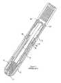
- FIG. 1is a perspective view of the inner housing from WO 2005/070481;
- FIG. 2(PRIOR ART) is a perspective view of a known injection device
- FIG. 3is a plan view, partly in section of the FIG. 2 device, with the cap and needle cover removed, ready for actuation;
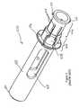
- FIG. 5is a perspective view of an alternative syringe holder from GB0620163.6;
- FIG. 6is a perspective view partly in section showing the inner housing in relation to the syringe holder from GB0620163.6;
- FIG. 7is a perspective view partly in section showing the inner housing in relation to the syringe holder, the syringe having a modified plunger according to a first embodiment of the invention
- FIG. 8is a perspective view of a modified inner housing
- FIG. 9is a perspective view of a further modified inner housing, embodying a second aspect of the invention.
- FIG. 10drawn to a larger scale, shows further detail of a part of the inner housing of FIG. 9 ;
- FIG. 11is a cross-sectional view of part of the inner housing of FIG. 9 ;
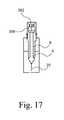
- FIGS. 12-17are schematic cross-sectional views of a second embodiment of the invention, showing various stages of operation of the device;
- FIG. 18is a schematic cross-sectional view of the rear part of the plunger having a ratchet cap.
- FIG. 19is a schematic cross-sectional view of the rear part of the plunger having an alternative embodiment of the ratchet cap.
- reference to a “forward” directionmeans the direction which is towards the patient when the injection device is in use.
- the “forward” end of the injection deviceis the end nearest the patient's skin when the device is in use.
- reference to a “rearward” directionmeans the direction which is away from the patient and the “rearward” end of the device is the end furthest from the patient's skin when the injection device is in use.
- the “plunger”does not necessarily (but may) include any elastomeric stopper or the like which seals the chamber containing liquid medicament.
- a first embodiment of the inventionis illustrated.
- a biasing meansin the form of a compression spring 200 between the rear of the outer housing 30 and the flange 8 F of the plunger 8 .
- the illustrated spring 200is integrally formed with the plunger flange 8 F, but alternatively, a separate spring could be provided.
- the spring 200has a flange 201 at the rear thereof to abut the rear of the outer housing.
- the spring 200is a compression spring so that the plunger flange 8 F is biased axially forwards so that the syringe as a whole is also biased axially forwards (the biasing force from the spring 200 being transmitted to the rest of the syringe including the barrel via the incompressible liquid medicament therein).
- the forward axial force provided by the spring 200is relatively weak and needs only be sufficient to bias the syringe forwards. The force is not sufficient to cause medicament to be ejected from the front of the device, nor is it sufficient to affect the operation of the main energy source (usually a much more powerful spring) which actuates the device when delivery of an injection is required.
- the axial position of the plungeris such that it is possible to for the tags 7 A, 7 B to be stored in their radially-outward position, which is preferable given the above-described tendency for the tags to acquire “memory” of their stored position.
- the front tags 7 Bare radially offset from the rear tags 7 A, for example by 45°, as illustrated in FIG. 8 .
- FIGS. 9-11An alternative embodiment of the invention is shown in FIGS. 9-11 .
- the biasing meansare provided as part of a modified inner housing.
- the inner housing 7has rear tags 7 A and front tags 7 B having the same function as described above.
- the front end of the inner housingis provided with one or more biasing means in the form of radially flexible legs 250 .
- the legsare preferably integrally formed with the inner housing 7 .
- Each flexible leg 250may have an enlarged head 251 .
- FIGS. 10 and 11show the finger flange 90 of the syringe barrel and the barrel seat 91 at the rear of the device's syringe holder.
- the legs 250may be moulded so that this is their default position.
- the legs 250need not abut the finger flange 90 (although they may do so) but they must at least partially block its rearward axial path. In this way, undesirable rearward axial movement of the finger flange 90 is prevented and the syringe barrel is biased to a position forward of the front tags 7 B.
- the performance of the deviceis improved, as one always knows that the syringe flange's initial axial position is biased forward of the rear tags 7 B, avoiding the risk of malfunction.
- the legs 250 of the inner housing 7are relatively weak and need only to be strong enough to resist the weight of the syringe to prevent undesirable axial movement. They do not impede the firing of the autoinjector to deliver medicament.
- the inner housing 7is urged forward by the full force of the main energy source.
- the legs 250cannot resist this force and so they are forced radially-outwardly, out of the path of the finger flange 90 . Therefore it is possible for the front tags 7 B to engage the finger flange 90 in the normal way to move the syringe axially forward enough to move the needle out of the housing into the injection site.
- FIGS. 12-17An alternative embodiment of the invention is shown schematically in FIGS. 12-17 .
- the rear of the plunger 8is attached to a chamber 300 filled with a shear thickening fluid.
- a shear thickening fluidis one whose viscosity increases with the rate of shear and is sometimes referred to as a “dilatant” material.
- the chamber 300is fixed with respect to the plunger 8 .
- the chamber 300contains an axially-moveable piston 301 which does not fill the cross-section of the chamber, so that the shear thickening fluid is able to pass freely around the piston.
- the piston 301is attached to and fixed with respect to a rear flange 302 .
- the rear tags 7 A of the inner housingengage behind the rear flange 302 , in the same way as if the rear flange were the flange of the plunger ( 8 F) in the FIG. 7 embodiment.
- a compression spring 303is disposed between the rear flange 302 and the rear surface of the chamber 300 , as shown in FIG. 12 , so that the rear flange 302 is always biased against the rear tags 7 A of the inner housing.
- the outer housing of the deviceis labelled as item 30 and the barrel of the syringe is labelled as item 9 in FIG. 12 .
- the chamber 300acts as a linear dashpot and, in combination with the spring 303 may be referred to as biasing means.
- FIG. 13shows what happens when the plunger 8 moves during storage and/or transportation of the device.
- the pressure inside the syringemay change if the device is transported by airfreight when any gas bubble inside the syringe may change in volume, causing the plunger 8 to move axially.
- the axial movementis relatively slow and is not forceful enough to change the viscosity of the shear thickening fluid. Consequently, as the plunger 8 moves rearwardly (upwards as illustrated in FIG. 13 ) so does the chamber 300 .
- the piston 301does not move rearwardly (as it is attached to the rear flange 302 ) and so the shear thickening fluid moves around it as the chamber moves rearwardly.
- the distance between the rear flange 302 and the rear surface of the chamber 300reduces as the spring 303 is compressed. If the plunger moves forwards, the opposite happens i.e. the distance between the rear flange 302 and the rear surface of the chamber 300 increases.
- the spring 303always keeps the rear flange 302 biased against the tags 7 A of the inner housing.
- FIG. 14shows what happens when the device is actuated to deliver an injection.
- the strong driving force of the device's main energy sourcecauses the viscosity of the shear thickening fluid to change and the fluid thickens.
- the thick fluidcan no longer move freely around the piston 301 and the chamber 300 acts, effectively, as a solid bridge between the rear flange 302 and the plunger 8 , so that the plunger 8 is driven into the barrel 9 of the syringe to deliver the medicament.
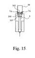
- FIG. 15shows what happens when the dose of medicament has been delivered.
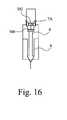
- the piston 301continues to move forwards, albeit at a reduced speed because the thickened shear thickening fluid is still able to flow to some extent. Therefore the inner housing 7 is able to continue forwards slightly after the full dose of medicament has been delivered. This extra forward movement ensures that the inner housing 7 reaches its desired forward position regardless of its absolute initial axial starting position. This is necessary in order for the rear tags 7 A to move radially-outwardly releasing the rear flange 302 as shown in FIG. 16 .
- the shear thickening fluid chamberprovides an axial range of possible initial starting points for the plunger 8 .
- the rear flange 302 , chamber 300 and plunger 8are free to move axially rearwardly under the force of a secondary spring at the front of the device (not illustrated).
- the needle 10 , syringe barrel 9 , plunger 8 , chamber 300 and rear flange 302can all retract into the device so that the needle is fully concealed from the patient's view.
- a significant advantage of the chamber of shear thickening fluidis that a precise absolute axial starting point of the plunger is no longer required for proper functioning of the device.
- the chamber of shear thickening fluidabsorbs the effect of minor axial movements of the plunger during storage and transportation.
- the shear thickening fluid chamberprovides an axial range of possible initial starting points for the plunger 8 .
- the shear thickening fluidenables a defined relative axial movement to occur in order to deliver the required dose.
- FIG. 18A further improvement is illustrated in FIG. 18 .
- a ratchet cap 400is provided which sites over the rear flange 8 F of the plunger 8 , locked into place by locking tabs 401 .
- the rear tags 7 A of the inner housingcan engage anywhere along the ratchet cap 400 , depending upon the absolute axial position of the plunger (and consequently the ratchet cap attached thereto). This also effectively provides a plurality of axial starting positions for the plunger for which the device will work to deliver the required dose of medicament.
- the ratchet cap embodimentcould be used in combination with the modified plunger rod of FIG. 7 .
- ratchet capmay be used to provide the range of axial starting positions for the plunger, for example a differently shaped component intermediate the inner housing tags and plunger.
- the ratchet cap or equivalent componentcould be an integral part of a modified plunger, for example a plunger having a plurality of annular ribs.
- the diameter of the inner housing 7may need to be increased slightly to accommodate the extra diameter of the ratchet cap.
- the ratchet capcould be shaped as shown in FIG. 19 so that the diameter of the device does not need to be increased.
- This embodimenthas the advantage that the overall length of the device could be reduced with the rear flange positioned further back in the device, inside the main spring (the device's main energy source).
Landscapes
- Health & Medical Sciences (AREA)
- Vascular Medicine (AREA)
- Engineering & Computer Science (AREA)
- Anesthesiology (AREA)
- Biomedical Technology (AREA)
- Heart & Thoracic Surgery (AREA)
- Hematology (AREA)
- Life Sciences & Earth Sciences (AREA)
- Animal Behavior & Ethology (AREA)
- General Health & Medical Sciences (AREA)
- Public Health (AREA)
- Veterinary Medicine (AREA)
- Infusion, Injection, And Reservoir Apparatuses (AREA)
Abstract
Description
- a barrel for holding a volume of medicament,
- a needle at one end of the barrel and
- a plunger axially-moveable in the barrel, the autoinjector further comprising an inner housing intermediate the outer housing and the syringe and an energy source in communication with said inner housing,
- wherein the inner housing is moveable by the energy source between three positions, namely
- a first position in which the inner housing is in communication with the barrel such that, in use, the plunger and barrel are moveable axially so as to move at least part of said needle out of the outer housing;
- a second position in which the inner housing is in communication with the plunger but not the barrel such that, in use, said plunger is moveable axially into said barrel so as to expel medicament through the needle; and
- a third position in which the inner housing is in communication with neither the plunger nor the barrel such that, in use, the plunger and barrel are able to retract in order to retract the needle into the outer housing,
characterised in that the autoinjector includes biasing means for axially biasing the barrel, before activation of the energy source, to a position forward of the part of the inner housing which acts on the barrel in said first position.
- a barrel for holding a volume of medicament,
- a needle at one end of the barrel and
- a plunger axially-moveable in the barrel,
the autoinjector further comprising an inner housing intermediate the outer housing and the syringe and an energy source in communication with said inner housing, - wherein the inner housing is moveable by the energy source between three positions, namely
- a first position in which the inner housing is in communication with the barrel such that, in use, the plunger and barrel are moveable axially so as to move at least part of said needle out of the outer housing;
- a second position in which the inner housing is in communication with the plunger but not the barrel such that, in use, said plunger is moveable axially into said barrel so as to expel medicament through the needle; and
- a third position in which the inner housing is in communication with neither the plunger nor the barrel such that, in use, the plunger and barrel are able to retract in order to retract the needle into the outer housing,
characterised in that the autoinjector further comprises means associated with a rear flange of said plunger providing a plurality of axial positions at which it is possible for said inner housing to engage said plunger in said second position.
Claims (19)
Applications Claiming Priority (3)
| Application Number | Priority Date | Filing Date | Title |
|---|---|---|---|
| GB0704351.6 | 2007-03-07 | ||
| GBGB0704351.6AGB0704351D0 (en) | 2007-03-07 | 2007-03-07 | Improved autoinjector |
| PCT/GB2008/000741WO2008107670A2 (en) | 2007-03-07 | 2008-03-04 | Improved autoinjector |
Publications (2)
| Publication Number | Publication Date |
|---|---|
| US20100130930A1 US20100130930A1 (en) | 2010-05-27 |
| US8187226B2true US8187226B2 (en) | 2012-05-29 |
Family
ID=37966048
Family Applications (2)
| Application Number | Title | Priority Date | Filing Date |
|---|---|---|---|
| US12/530,107Active2028-05-04US8187226B2 (en) | 2007-03-07 | 2008-03-04 | Autoinjector |
| US13/189,286ActiveUS8308697B2 (en) | 2007-03-07 | 2011-07-22 | Autoinjector |
Family Applications After (1)
| Application Number | Title | Priority Date | Filing Date |
|---|---|---|---|
| US13/189,286ActiveUS8308697B2 (en) | 2007-03-07 | 2011-07-22 | Autoinjector |
Country Status (5)
| Country | Link |
|---|---|
| US (2) | US8187226B2 (en) |
| EP (1) | EP2131899B1 (en) |
| ES (1) | ES2667755T3 (en) |
| GB (2) | GB0704351D0 (en) |
| WO (1) | WO2008107670A2 (en) |
Cited By (8)
| Publication number | Priority date | Publication date | Assignee | Title |
|---|---|---|---|---|
| US20120022465A1 (en)* | 2007-03-07 | 2012-01-26 | The Medical House Limited | Autoinjector |
| US8734402B2 (en) | 2009-01-20 | 2014-05-27 | Future Injection Technologies Limited | Injection device |
| US8734393B2 (en) | 2009-04-23 | 2014-05-27 | The Medical House Limited | Autoinjector |
| US9675754B2 (en) | 2012-10-24 | 2017-06-13 | Nuance Designs, LLC | Autoinjector |
| US11052199B2 (en)* | 2015-06-05 | 2021-07-06 | Aptar France Sas | Auto-injector |
| US11642462B2 (en) | 2006-01-23 | 2023-05-09 | Shl Medical Ag | Injection device |
| US11883260B2 (en) | 2014-12-23 | 2024-01-30 | Automed Patent Holdco, Llc | Delivery apparatus, system and associated methods |
| US11957542B2 (en) | 2020-04-30 | 2024-04-16 | Automed Patent Holdco, Llc | Sensing complete injection for animal injection device |
Families Citing this family (35)
| Publication number | Priority date | Publication date | Assignee | Title |
|---|---|---|---|---|
| FR2852851B1 (en)* | 2003-03-25 | 2006-01-06 | Sedat | NEEDLE PROTECTION DEVICE FOR SYRINGE, AND INJECTION DEVICE COMPRISING SYRINGE AND PROTECTIVE DEVICE |
| FR2861310B1 (en)* | 2003-10-22 | 2006-09-22 | Plastef Investissements | SECURE INJECTION SYRINGE DEVICE |
| GB2410188B (en)* | 2004-01-23 | 2006-01-25 | Medical House Plc | Injection device |
| GB0601309D0 (en) | 2006-01-23 | 2006-03-01 | Medical House The Plc | Injection device |
| GB0625169D0 (en) | 2006-12-18 | 2007-01-24 | Medical House Plc The | Improved autoinjector |
| FR2922455B1 (en) | 2007-10-23 | 2010-10-29 | Plastef Investissements | SYRINGE DEVICE COMPRISING A SYRINGE BODY AND A SUPPORT SLEEVE. |
| US8052645B2 (en) | 2008-07-23 | 2011-11-08 | Avant Medical Corp. | System and method for an injection using a syringe needle |
| US8177749B2 (en) | 2008-05-20 | 2012-05-15 | Avant Medical Corp. | Cassette for a hidden injection needle |
| CA3070618C (en) | 2008-05-20 | 2021-07-20 | Avant Medical Corp. | Autoinjector system |
| JP5570534B2 (en) | 2009-03-06 | 2014-08-13 | サノフィ−アベンティス・ドイチュラント・ゲゼルシャフト・ミット・ベシュレンクテル・ハフツング | Syringe, self-injection device, and set of self-injection device and syringe |
| DK2536452T3 (en) | 2010-02-18 | 2019-01-02 | Sanofi Aventis Deutschland | autoinjector |
| EP2364739A1 (en) | 2010-03-09 | 2011-09-14 | Sanofi-Aventis Deutschland GmbH | Re-usable autoinjector |
| EP2364741A1 (en)* | 2010-03-09 | 2011-09-14 | Sanofi-Aventis Deutschland GmbH | Interlock mechanism for defining an operation sequence of an auto-injector |
| EP2364740A1 (en)* | 2010-03-09 | 2011-09-14 | Sanofi-Aventis Deutschland GmbH | Arrangement for transferring a translation of a drive means to a plunger |
| US9022990B2 (en)* | 2011-04-04 | 2015-05-05 | Tech Group Europe Limited | Needle safety shield |
| PL2699293T3 (en) | 2011-04-20 | 2019-08-30 | Amgen Inc. | Autoinjector apparatus |
| TWD152768S (en)* | 2011-07-27 | 2013-04-01 | 久光製藥股份有限公司 | Applicator device |
| KR101973824B1 (en) | 2011-07-27 | 2019-04-29 | 히사미쓰 세이야꾸 가부시키가이샤 | Applicator |
| EP2601992A1 (en) | 2011-12-08 | 2013-06-12 | Sanofi-Aventis Deutschland GmbH | Syringe carrier |
| KR20170105136A (en)* | 2011-12-15 | 2017-09-18 | 에스에이치엘 그룹 에이비 | Auto-injection device |
| USD808010S1 (en) | 2012-04-20 | 2018-01-16 | Amgen Inc. | Injection device |
| USD898908S1 (en) | 2012-04-20 | 2020-10-13 | Amgen Inc. | Pharmaceutical product cassette for an injection device |
| DE102012105843B4 (en)* | 2012-07-02 | 2015-11-05 | Gerresheimer Regensburg Gmbh | Device for receiving a hypodermic syringe and hypodermic syringe therefor |
| EP2716316A1 (en)* | 2012-10-04 | 2014-04-09 | Sanofi-Aventis Deutschland GmbH | Medicament delivery device with damping mechanism |
| US9050416B2 (en) | 2012-11-01 | 2015-06-09 | Tech Group Europe Limited | Needle Safety device with floating ring |
| EP2777684A1 (en) | 2013-03-14 | 2014-09-17 | Sanofi-Aventis Deutschland GmbH | Medicament container carrier and adapter |
| CA2904661C (en) | 2013-03-15 | 2022-03-15 | Amgen Inc. | Drug cassette, autoinjector, and autoinjector system |
| ES2973257T3 (en) | 2013-03-15 | 2024-06-19 | Amgen Inc | Drug cassette, autoinjector and autoinjector system |
| EP2823841A1 (en) | 2013-07-09 | 2015-01-14 | Sanofi-Aventis Deutschland GmbH | Autoinjector |
| EP2923714A1 (en) | 2014-03-28 | 2015-09-30 | Sanofi-Aventis Deutschland GmbH | Autoinjector triggered by skin contact |
| CN107530502B (en) | 2015-02-20 | 2021-01-15 | 里珍纳龙药品有限公司 | Syringe system, piston sealing system, stopper system |
| TW201705994A (en) | 2015-06-03 | 2017-02-16 | 賽諾菲阿凡提斯德意志有限公司 | Automatic syringe and assembly method |
| TW201700117A (en) | 2015-06-03 | 2017-01-01 | 賽諾菲阿凡提斯德意志有限公司 | Syringe bracket and assembly method for autoinjector |
| CA3027884A1 (en)* | 2015-06-15 | 2016-12-22 | Nuance Designs Of Ct, Llc | Autoinjector |
| EP3448465B1 (en)* | 2016-04-29 | 2021-06-02 | Altaviz LLC | Self-powered syringe |
Citations (78)
| Publication number | Priority date | Publication date | Assignee | Title |
|---|---|---|---|---|
| US60917A (en) | 1867-01-01 | Anson r | ||
| GB886444A (en) | 1958-12-11 | 1962-01-10 | American Home Prod | Injection syringe and combination thereof with a cartridge |
| US3702608A (en)* | 1970-12-15 | 1972-11-14 | Robert C Tibbs | Painless injection device with powered plunger |
| US3756242A (en) | 1972-01-04 | 1973-09-04 | Micro Motors Inc | Mechanical scarifier |
| US3797489A (en) | 1972-02-10 | 1974-03-19 | Survival Technology | Hypodermic injection device with shock absorbing spring |
| US3811442A (en) | 1972-03-23 | 1974-05-21 | A Maroth | Hypodermic syringe holder and applicator |
| US4617016A (en) | 1981-12-14 | 1986-10-14 | Anders Blomberg | Injection device |
| US4913699A (en) | 1988-03-14 | 1990-04-03 | Parsons James S | Disposable needleless injection system |
| US4923447A (en) | 1989-02-17 | 1990-05-08 | Morgan Michael W | Syringe assembly |
| US4958622A (en) | 1983-05-11 | 1990-09-25 | Selenke William M | Hypodermic syringe for taking and transporting a specimen |
| US4976724A (en) | 1989-08-25 | 1990-12-11 | Lifescan, Inc. | Lancet ejector mechanism |
| US5024656A (en) | 1988-08-30 | 1991-06-18 | Injet Medical Products, Inc. | Gas-pressure-regulated needleless injection system |
| US5042977A (en) | 1987-05-08 | 1991-08-27 | Wilhelm Haselmeier Gmbh & Co. | Injection device which can be cocked only in the zero position |
| EP0453212A1 (en) | 1990-04-16 | 1991-10-23 | Minimed Inc., doing business as Minimed Technologies | Infusion pump with dual position syringe locator |
| US5078698A (en) | 1991-02-19 | 1992-01-07 | Sterling Drug Inc. | Axial eject hypodermic syringe holder |
| US5167632A (en) | 1992-01-24 | 1992-12-01 | New Potency Products, Inc. | Syringe |
| EP0518416A1 (en) | 1991-06-13 | 1992-12-16 | Duphar International Research B.V | Injection device |
| US5211625A (en) | 1990-03-20 | 1993-05-18 | Olympus Optical Co., Ltd. | Ultrasonic treatment apparatus |
| US5300030A (en) | 1991-05-30 | 1994-04-05 | Owen Mumford Limited | Injection devices |
| US5320609A (en) | 1992-12-07 | 1994-06-14 | Habley Medical Technology Corporation | Automatic pharmaceutical dispensing syringe |
| WO1994021316A1 (en) | 1993-03-24 | 1994-09-29 | Owen Mumford Limited | Improvements relating to injection devices |
| US5478316A (en) | 1994-02-02 | 1995-12-26 | Becton, Dickinson And Company | Automatic self-injection device |
| US5568261A (en) | 1992-12-18 | 1996-10-22 | Kabushiki Kaisha Komatsu Seisakusho | Three-dimensional image measuring device |
| EP0740942A1 (en) | 1995-05-04 | 1996-11-06 | Sanofi | Process of manufacturing a prefilled injection device and injection device produced thereby |
| US5634906A (en) | 1995-12-27 | 1997-06-03 | Habley Medical Technology Corporation | Needle hiding shield for a dose metering syringe |
| US5658261A (en) | 1991-06-07 | 1997-08-19 | Liebel-Flarsheim Company | Disposable front loadable syringe |
| US5681291A (en) | 1992-11-19 | 1997-10-28 | Tebro S.A. | Disposable auto-injector for prefilled syringes |
| US5779677A (en) | 1994-01-17 | 1998-07-14 | Laboratoire Aguettant | Automatic drug injector |
| US5779675A (en) | 1995-08-25 | 1998-07-14 | Medrad, Inc. | Front load pressure jacket system with syringe holder |
| EP0864335A2 (en) | 1997-03-10 | 1998-09-16 | Safety Syringes, Inc. | Syringe guard |
| WO1999022792A1 (en) | 1997-11-03 | 1999-05-14 | Ermanno Greco | Self-injection device |
| WO2000009186A2 (en) | 1998-08-11 | 2000-02-24 | Medi-Ject Corporation | Needle assisted jet injector |
| US6203530B1 (en) | 1997-01-28 | 2001-03-20 | Pos-T-Vac, Inc. | Auto-injection device |
| US6210369B1 (en) | 1997-12-16 | 2001-04-03 | Meridian Medical Technologies Inc. | Automatic injector |
| US20010005781A1 (en) | 1998-10-26 | 2001-06-28 | Thomas Bergens | Autoinjector |
| US6264629B1 (en) | 1998-11-18 | 2001-07-24 | Bioject, Inc. | Single-use needle-less hypodermic jet injection apparatus and method |
| US6280421B1 (en) | 1998-05-15 | 2001-08-28 | Disetronic Licensing Ag | Automatic injection device |
| WO2001093926A2 (en) | 2000-06-08 | 2001-12-13 | Mayo Foundation For Medical Education And Research | Automated injection device for administration of liquid medicament |
| WO2002070051A1 (en) | 2001-03-05 | 2002-09-12 | Bioject Medical Technologies Inc. | Disposable needle-free injection apparatus and method |
| US6544234B1 (en) | 1998-01-24 | 2003-04-08 | B D Medico S.A.R.L. | Injection device |
| US20030105430A1 (en) | 2001-11-30 | 2003-06-05 | Elan Pharma International Limited Wil House | Automatic injector |
| EP1323447A2 (en) | 1999-10-15 | 2003-07-02 | Becton, Dickinson and Company | Retracting needle syringe |
| EP1323477A2 (en) | 2001-12-20 | 2003-07-02 | Fleetguard, Inc. | Self-driven centrifuge with vane module |
| US6605072B2 (en) | 2000-05-03 | 2003-08-12 | Aspect Medical Systems, Inc. | System and method for adaptive drug delivery |
| US6607510B2 (en) | 2001-11-09 | 2003-08-19 | Bioject Medical Technologies Inc. | Disposable needle-free injection apparatus and method |
| GB2388033A (en) | 2002-05-02 | 2003-11-05 | Pa Consulting Services | Automatic injection device |
| WO2003097133A1 (en) | 2002-05-17 | 2003-11-27 | Owen Mumford Limited | Injection device with automatically retractable needle |
| US6656163B1 (en) | 1997-08-21 | 2003-12-02 | Ares-Trading S.A. | Injection devices |
| WO2003099358A2 (en) | 2002-05-23 | 2003-12-04 | Seedlings Life Science Ventures, Llc. | Apparatus for rapid auto-injection of medication |
| US20030236502A1 (en) | 2001-11-09 | 2003-12-25 | De La Serna Pedro E. | Collapsible syringe cartridge |
| US6689093B2 (en) | 1998-11-18 | 2004-02-10 | Bioject, Inc. | Single-use needle-less hypodermic jet injection apparatus and method |
| US6702608B2 (en) | 2001-05-16 | 2004-03-09 | Bernard A. Brennan, Jr. | Electric workstation with power reel cords |
| US6752781B2 (en) | 2001-06-08 | 2004-06-22 | Sergio Landau | Durable hypodermic jet injector apparatus and method |
| GB2396298A (en) | 2002-12-17 | 2004-06-23 | Pa Consulting Services | Injection device and drive coupling |
| GB2397767A (en) | 2002-12-17 | 2004-08-04 | Pa Consulting Services | Injection device |
| US20050027255A1 (en) | 2003-07-31 | 2005-02-03 | Sid Technologies, Llc | Automatic injector |
| WO2005009520A1 (en) | 2003-07-22 | 2005-02-03 | Safety Syringes, Inc. | Systems and methods for automatic medical injection with needle guard |
| GB2410188A (en) | 2004-01-23 | 2005-07-27 | Medical House Plc | Retracting injection device |
| US20050165349A1 (en) | 2004-01-26 | 2005-07-28 | Kevin Stamp | Needle-free injection device |
| DE102004060146A1 (en) | 2003-12-18 | 2005-08-04 | Tecpharma Licensing Ag | Automatic injection apparatus has latching element that contacts with flange arranged at sliding sleeve, to prevent displacement of activator container when needle protection cap is removed from apparatus |
| WO2005070481A1 (en) | 2004-01-23 | 2005-08-04 | The Medical House Plc | Injection device |
| WO2005097252A2 (en) | 2004-04-05 | 2005-10-20 | Medrad, Inc. | Fluid injection apparatus with front load pressure jacket, light illumination, and syringe sensing |
| GB2414398A (en) | 2004-05-28 | 2005-11-30 | Cilag Ag Int | Injection Device. |
| WO2005115512A1 (en) | 2004-05-28 | 2005-12-08 | Cilag Gmbh International | Injection device |
| WO2005115507A1 (en) | 2004-05-28 | 2005-12-08 | Cilag Gmbh International | Injection device |
| US6981499B2 (en) | 1999-12-11 | 2006-01-03 | Glaxo Group Limited | Medicament dispenser |
| US20060100589A1 (en) | 2004-08-10 | 2006-05-11 | Biotop Technology Co. Ltd. | Syringe safety sleeve |
| WO2006052737A1 (en) | 2004-11-04 | 2006-05-18 | Sid Technologies, Llc | Automatic injector |
| WO2006106291A1 (en) | 2005-04-06 | 2006-10-12 | Cilag Ag International | Injection device |
| WO2006106295A1 (en) | 2005-04-06 | 2006-10-12 | Cilag Ag International | Injection device (adaptable device) |
| US7156823B2 (en) | 2002-06-04 | 2007-01-02 | Bioject Inc. | High workload needle-free injection system |
| WO2007083115A1 (en) | 2006-01-23 | 2007-07-26 | The Medical House Plc | Improved autoinjector supporting the syringe at the front |
| US20070173770A1 (en) | 2006-01-23 | 2007-07-26 | The Medical House Plc | Injection device |
| WO2007132353A2 (en) | 2006-04-11 | 2007-11-22 | Becton Dickinson France S.A.S | Automatic injection device |
| WO2008075033A1 (en) | 2006-12-18 | 2008-06-26 | The Medical House Plc | Improved autoinjector |
| WO2008107670A2 (en) | 2007-03-07 | 2008-09-12 | The Medical House Plc | Improved autoinjector |
| EP2080532A1 (en) | 2008-01-17 | 2009-07-22 | Peter Loss und Arnold Neuhold Gewerbliche Schutzrechte GbR | Cartridge for an autoinjector and system made up of such a cartridge and an autoinjector |
| WO2010026414A1 (en) | 2008-09-02 | 2010-03-11 | Owen Mumford Limited | Syringe safety shields and autoinjector |
Family Cites Families (4)
| Publication number | Priority date | Publication date | Assignee | Title |
|---|---|---|---|---|
| US4990142A (en) | 1989-10-23 | 1991-02-05 | Gte Products Corporation | Hypodermic syringe |
| EP1605992B1 (en)* | 2003-01-30 | 2018-11-21 | Becton, Dickinson and Company | Holder with safety shield for a drug delivery device |
| GB2414775B (en)* | 2004-05-28 | 2008-05-21 | Cilag Ag Int | Releasable coupling and injection device |
| US20060069350A1 (en)* | 2004-09-30 | 2006-03-30 | Buenger David R | Medical syringe injector pen |
- 2007
- 2007-03-07GBGBGB0704351.6Apatent/GB0704351D0/ennot_activeCeased
- 2008
- 2008-03-04USUS12/530,107patent/US8187226B2/enactiveActive
- 2008-03-04WOPCT/GB2008/000741patent/WO2008107670A2/enactiveApplication Filing
- 2008-03-04GBGB0804021Apatent/GB2447339A/ennot_activeWithdrawn
- 2008-03-04EPEP08718605.2Apatent/EP2131899B1/enactiveActive
- 2008-03-04ESES08718605.2Tpatent/ES2667755T3/enactiveActive
- 2011
- 2011-07-22USUS13/189,286patent/US8308697B2/enactiveActive
Patent Citations (90)
| Publication number | Priority date | Publication date | Assignee | Title |
|---|---|---|---|---|
| US60917A (en) | 1867-01-01 | Anson r | ||
| GB886444A (en) | 1958-12-11 | 1962-01-10 | American Home Prod | Injection syringe and combination thereof with a cartridge |
| US3702608A (en)* | 1970-12-15 | 1972-11-14 | Robert C Tibbs | Painless injection device with powered plunger |
| US3756242A (en) | 1972-01-04 | 1973-09-04 | Micro Motors Inc | Mechanical scarifier |
| US3797489A (en) | 1972-02-10 | 1974-03-19 | Survival Technology | Hypodermic injection device with shock absorbing spring |
| US3811442A (en) | 1972-03-23 | 1974-05-21 | A Maroth | Hypodermic syringe holder and applicator |
| US4617016A (en) | 1981-12-14 | 1986-10-14 | Anders Blomberg | Injection device |
| US4958622A (en) | 1983-05-11 | 1990-09-25 | Selenke William M | Hypodermic syringe for taking and transporting a specimen |
| US5042977A (en) | 1987-05-08 | 1991-08-27 | Wilhelm Haselmeier Gmbh & Co. | Injection device which can be cocked only in the zero position |
| US4913699A (en) | 1988-03-14 | 1990-04-03 | Parsons James S | Disposable needleless injection system |
| US5024656A (en) | 1988-08-30 | 1991-06-18 | Injet Medical Products, Inc. | Gas-pressure-regulated needleless injection system |
| US4923447A (en) | 1989-02-17 | 1990-05-08 | Morgan Michael W | Syringe assembly |
| US4976724A (en) | 1989-08-25 | 1990-12-11 | Lifescan, Inc. | Lancet ejector mechanism |
| US5211625A (en) | 1990-03-20 | 1993-05-18 | Olympus Optical Co., Ltd. | Ultrasonic treatment apparatus |
| EP0453212A1 (en) | 1990-04-16 | 1991-10-23 | Minimed Inc., doing business as Minimed Technologies | Infusion pump with dual position syringe locator |
| US5078698A (en) | 1991-02-19 | 1992-01-07 | Sterling Drug Inc. | Axial eject hypodermic syringe holder |
| US5300030A (en) | 1991-05-30 | 1994-04-05 | Owen Mumford Limited | Injection devices |
| US5658261A (en) | 1991-06-07 | 1997-08-19 | Liebel-Flarsheim Company | Disposable front loadable syringe |
| EP0518416A1 (en) | 1991-06-13 | 1992-12-16 | Duphar International Research B.V | Injection device |
| US5167632A (en) | 1992-01-24 | 1992-12-01 | New Potency Products, Inc. | Syringe |
| US5681291A (en) | 1992-11-19 | 1997-10-28 | Tebro S.A. | Disposable auto-injector for prefilled syringes |
| US5320609A (en) | 1992-12-07 | 1994-06-14 | Habley Medical Technology Corporation | Automatic pharmaceutical dispensing syringe |
| US5568261A (en) | 1992-12-18 | 1996-10-22 | Kabushiki Kaisha Komatsu Seisakusho | Three-dimensional image measuring device |
| US5599309A (en)* | 1993-03-24 | 1997-02-04 | Owen Mumford Limited | Injection devices |
| WO1994021316A1 (en) | 1993-03-24 | 1994-09-29 | Owen Mumford Limited | Improvements relating to injection devices |
| US5779677A (en) | 1994-01-17 | 1998-07-14 | Laboratoire Aguettant | Automatic drug injector |
| US5478316A (en) | 1994-02-02 | 1995-12-26 | Becton, Dickinson And Company | Automatic self-injection device |
| EP0740942A1 (en) | 1995-05-04 | 1996-11-06 | Sanofi | Process of manufacturing a prefilled injection device and injection device produced thereby |
| US5779675A (en) | 1995-08-25 | 1998-07-14 | Medrad, Inc. | Front load pressure jacket system with syringe holder |
| US5634906A (en) | 1995-12-27 | 1997-06-03 | Habley Medical Technology Corporation | Needle hiding shield for a dose metering syringe |
| US6203530B1 (en) | 1997-01-28 | 2001-03-20 | Pos-T-Vac, Inc. | Auto-injection device |
| EP0864335A2 (en) | 1997-03-10 | 1998-09-16 | Safety Syringes, Inc. | Syringe guard |
| US6656163B1 (en) | 1997-08-21 | 2003-12-02 | Ares-Trading S.A. | Injection devices |
| WO1999022792A1 (en) | 1997-11-03 | 1999-05-14 | Ermanno Greco | Self-injection device |
| US6210369B1 (en) | 1997-12-16 | 2001-04-03 | Meridian Medical Technologies Inc. | Automatic injector |
| US6544234B1 (en) | 1998-01-24 | 2003-04-08 | B D Medico S.A.R.L. | Injection device |
| US6620137B2 (en) | 1998-05-15 | 2003-09-16 | Disetronic Licensing Ag | Automatic injection device |
| US6280421B1 (en) | 1998-05-15 | 2001-08-28 | Disetronic Licensing Ag | Automatic injection device |
| US20010049496A1 (en)* | 1998-05-15 | 2001-12-06 | Fritz Kirchhofer | Automatic injection device |
| WO2000009186A2 (en) | 1998-08-11 | 2000-02-24 | Medi-Ject Corporation | Needle assisted jet injector |
| US6270479B1 (en)* | 1998-10-26 | 2001-08-07 | Pharmacia Ab | Autoinjector |
| US20010005781A1 (en) | 1998-10-26 | 2001-06-28 | Thomas Bergens | Autoinjector |
| US6264629B1 (en) | 1998-11-18 | 2001-07-24 | Bioject, Inc. | Single-use needle-less hypodermic jet injection apparatus and method |
| US6689093B2 (en) | 1998-11-18 | 2004-02-10 | Bioject, Inc. | Single-use needle-less hypodermic jet injection apparatus and method |
| EP1323447A2 (en) | 1999-10-15 | 2003-07-02 | Becton, Dickinson and Company | Retracting needle syringe |
| US6632198B2 (en) | 1999-10-15 | 2003-10-14 | Becton Dickinson And Company | Retracting needle syringe |
| US6981499B2 (en) | 1999-12-11 | 2006-01-03 | Glaxo Group Limited | Medicament dispenser |
| US6605072B2 (en) | 2000-05-03 | 2003-08-12 | Aspect Medical Systems, Inc. | System and method for adaptive drug delivery |
| WO2001093926A2 (en) | 2000-06-08 | 2001-12-13 | Mayo Foundation For Medical Education And Research | Automated injection device for administration of liquid medicament |
| WO2002070051A1 (en) | 2001-03-05 | 2002-09-12 | Bioject Medical Technologies Inc. | Disposable needle-free injection apparatus and method |
| US6702608B2 (en) | 2001-05-16 | 2004-03-09 | Bernard A. Brennan, Jr. | Electric workstation with power reel cords |
| US6752781B2 (en) | 2001-06-08 | 2004-06-22 | Sergio Landau | Durable hypodermic jet injector apparatus and method |
| US20030236502A1 (en) | 2001-11-09 | 2003-12-25 | De La Serna Pedro E. | Collapsible syringe cartridge |
| US6607510B2 (en) | 2001-11-09 | 2003-08-19 | Bioject Medical Technologies Inc. | Disposable needle-free injection apparatus and method |
| US20030105430A1 (en) | 2001-11-30 | 2003-06-05 | Elan Pharma International Limited Wil House | Automatic injector |
| EP1323477A2 (en) | 2001-12-20 | 2003-07-02 | Fleetguard, Inc. | Self-driven centrifuge with vane module |
| GB2388033A (en) | 2002-05-02 | 2003-11-05 | Pa Consulting Services | Automatic injection device |
| WO2003097133A1 (en) | 2002-05-17 | 2003-11-27 | Owen Mumford Limited | Injection device with automatically retractable needle |
| WO2003099358A2 (en) | 2002-05-23 | 2003-12-04 | Seedlings Life Science Ventures, Llc. | Apparatus for rapid auto-injection of medication |
| US7156823B2 (en) | 2002-06-04 | 2007-01-02 | Bioject Inc. | High workload needle-free injection system |
| GB2396298A (en) | 2002-12-17 | 2004-06-23 | Pa Consulting Services | Injection device and drive coupling |
| GB2397767A (en) | 2002-12-17 | 2004-08-04 | Pa Consulting Services | Injection device |
| WO2005009520A1 (en) | 2003-07-22 | 2005-02-03 | Safety Syringes, Inc. | Systems and methods for automatic medical injection with needle guard |
| US20050027255A1 (en) | 2003-07-31 | 2005-02-03 | Sid Technologies, Llc | Automatic injector |
| WO2005009515A1 (en) | 2003-07-31 | 2005-02-03 | Sid Technologies Llc | Injecting apparatus |
| DE102004060146A1 (en) | 2003-12-18 | 2005-08-04 | Tecpharma Licensing Ag | Automatic injection apparatus has latching element that contacts with flange arranged at sliding sleeve, to prevent displacement of activator container when needle protection cap is removed from apparatus |
| GB2410188A (en) | 2004-01-23 | 2005-07-27 | Medical House Plc | Retracting injection device |
| WO2005070481A1 (en) | 2004-01-23 | 2005-08-04 | The Medical House Plc | Injection device |
| US20100069846A1 (en) | 2004-01-23 | 2010-03-18 | The Medical House Plc | Injection device |
| US20080228143A1 (en) | 2004-01-23 | 2008-09-18 | The Medical House Plc | Injection Device |
| US20050165360A1 (en) | 2004-01-23 | 2005-07-28 | Kevin Stamp | Injection device |
| US20050165349A1 (en) | 2004-01-26 | 2005-07-28 | Kevin Stamp | Needle-free injection device |
| WO2005097252A2 (en) | 2004-04-05 | 2005-10-20 | Medrad, Inc. | Fluid injection apparatus with front load pressure jacket, light illumination, and syringe sensing |
| WO2005115507A1 (en) | 2004-05-28 | 2005-12-08 | Cilag Gmbh International | Injection device |
| GB2414398A (en) | 2004-05-28 | 2005-11-30 | Cilag Ag Int | Injection Device. |
| WO2005115512A1 (en) | 2004-05-28 | 2005-12-08 | Cilag Gmbh International | Injection device |
| US20090012471A1 (en) | 2004-05-28 | 2009-01-08 | Cilag Ag Interntional | Injection Device |
| US20060100589A1 (en) | 2004-08-10 | 2006-05-11 | Biotop Technology Co. Ltd. | Syringe safety sleeve |
| US20070265568A1 (en) | 2004-11-04 | 2007-11-15 | Izrail Tsals | Automatic Injector |
| WO2006052737A1 (en) | 2004-11-04 | 2006-05-18 | Sid Technologies, Llc | Automatic injector |
| WO2006106291A1 (en) | 2005-04-06 | 2006-10-12 | Cilag Ag International | Injection device |
| WO2006106295A1 (en) | 2005-04-06 | 2006-10-12 | Cilag Ag International | Injection device (adaptable device) |
| WO2007083115A1 (en) | 2006-01-23 | 2007-07-26 | The Medical House Plc | Improved autoinjector supporting the syringe at the front |
| US20070173770A1 (en) | 2006-01-23 | 2007-07-26 | The Medical House Plc | Injection device |
| WO2007132353A2 (en) | 2006-04-11 | 2007-11-22 | Becton Dickinson France S.A.S | Automatic injection device |
| US7976499B2 (en)* | 2006-04-11 | 2011-07-12 | Becton, Dickinson And Company | Automatic injection device |
| WO2008075033A1 (en) | 2006-12-18 | 2008-06-26 | The Medical House Plc | Improved autoinjector |
| WO2008107670A2 (en) | 2007-03-07 | 2008-09-12 | The Medical House Plc | Improved autoinjector |
| EP2080532A1 (en) | 2008-01-17 | 2009-07-22 | Peter Loss und Arnold Neuhold Gewerbliche Schutzrechte GbR | Cartridge for an autoinjector and system made up of such a cartridge and an autoinjector |
| WO2010026414A1 (en) | 2008-09-02 | 2010-03-11 | Owen Mumford Limited | Syringe safety shields and autoinjector |
Non-Patent Citations (46)
| Title |
|---|
| Advisiory Action for U.S. Appl. No. 10/767,860, mailed Sep. 5, 2008, 3 pages. |
| Authorized Officer Bjorklund, Written Opinon for International (PCT) Patent Application No. PCT/GB2007/000141, mailed May 5, 2007, 7 pages. |
| Authorized Officer Mulhausen, International Preliminary Report on Patentability for International (PCT) Patent Application No. PCT/GB2007/000141, mailed Jul. 29, 2008, 8 pages. |
| Authorized Officer Mulhausen, International Preliminary Report on Patentability issued on Jun. 24, 2009 for International Application No. PCT/GB2007/004870, 8 pages. |
| Authorized Officer Reinbold, International Preliminary Report on Patentability for International (PCT) Patent Application No. PCT/GB2005/000223, mailed Jan. 23, 2006, 13 pages. |
| Authorized Officer Reinbold, International Search Report issued by the European Patent Office on Mar. 19, 2008 for International Application No. PCT/GB2007/004870, 3 pages. |
| Authorized Officer Reinbold, Written Opinion for International (PCT) Patent Application No. PCT/GB2005/000223, mailed Jun. 22, 2005, 7 pages. |
| Authorized Officer Reinbold, Written Opinion issued by the European Patent Office on Mar. 19, 2008 for International Application No. PCT/GB2007/004870, 7 pages. |
| Corrected Search Report under Section 17 for Application No. GB0620163.6, dated Nov. 24, 2006, 1 page. |
| Formalities Officer Sulis, Communication pursuant to Rule 114(2) EPC for European Patent Application No. 07704923.4, mailed Sep. 29, 2010, 9 pages. |
| International Preliminary Report on Patentability issued by the International Bureau of WIPO on Sep. 17, 2009, pp. 1-13. |
| International Search Report for International (PCT) Patent Application No. PCT/GB2007/000141, mailed May 5, 2007, 2 pages. |
| International Search Report issued by the European Patent Office on Dec. 23, 2008, for International Application No. PCT/GB2008/000741, pp. 1-8. |
| International Search Report issued by the European Patent Office on May 19, 2010, for International Application No. PCT/GB2009/051716. |
| Interview Summary for U.S. Appl. No. 10/767,860, mailed Feb. 2, 2009, 4 pages. |
| Notice of Allowance for U.S. Appl. No. 10/597,379, mailed Sep. 2, 2009, 11 pages. |
| Notice of Allowance for U.S. Appl. No. 10/767,860, mailed Aug. 27, 2009, 8 pages. |
| Official Action for U.S. Appl. No. 10/597,379, mailed Feb. 23, 2009, 9 pages. |
| Official Action for U.S. Appl. No. 10/597,379, mailed Jul. 31, 2008, 12 pages. |
| Official Action for U.S. Appl. No. 10/767,859, mailed Dec. 28, 2007, 8 pages. |
| Official Action for U.S. Appl. No. 10/767,859, mailed Feb. 24, 2006, 8 pages. |
| Official Action for U.S. Appl. No. 10/767,859, mailed Jun. 5, 2007, 8 pages. |
| Official Action for U.S. Appl. No. 10/767,859, mailed Sep. 12, 2006, 10 pages. |
| Official Action for U.S. Appl. No. 10/767,860, mailed Apr. 10, 2007, 7 pages. |
| Official Action for U.S. Appl. No. 10/767,860, mailed Aug. 22, 2006, 8 pages. |
| Official Action for U.S. Appl. No. 10/767,860, mailed Dec. 15, 2006, 3 pages. |
| Official Action for U.S. Appl. No. 10/767,860, mailed Dec. 2, 2008, 5 pages. |
| Official Action for U.S. Appl. No. 10/767,860, mailed Jan. 11, 2008, 8 pages. |
| Official Action for U.S. Appl. No. 10/767,860, mailed Jun. 12, 2008, 6 pages. |
| Official Action for U.S. Appl. No. 10/767,860, mailed Mar. 14, 2006, 8 pages. |
| Official Action for U.S. Appl. No. 10/767,860, mailed Sep. 24, 2007. |
| Official Action for U.S. Appl. No. 11/387,645, mailed Feb. 11, 2011, 29 pages. |
| Official Action for U.S. Appl. No. 11/387,645, mailed Sep. 17, 2010, 29 pages. |
| Official Action for U.S. Appl. No. 12/161,776, mailed May 11, 2011, 11 pages. |
| Official Action for U.S. Appl. No. 12/623,960, mailed Mar. 5, 2012, 11 pages. |
| Official Action for U.S. Appl. No. 13/189,286, mailed Jan. 4, 2012, 9 pages. |
| Official Action for U.S. Patent Application No. 12/161,776, mailed Oct. 6, 2010, 21 pages. |
| Restriction Requirement for U.S. Appl. No. 11/387,645, mailed May 28, 2009, 7 pages. |
| Restriction Requirement for U.S. Appl. No. 12/623,960, mailed Jan. 5, 2012, 6 pages. |
| Search Report issued by the UK Intellectual Property Office on Jul. 1, 2008, for Application No. GB0804021.4, pp. 1-4. |
| Search Report issued by the UK Intellectual Property Office on Jun. 7, 2007, for Application No. GB0704351.6, pp. 1-4. |
| U.S. Appl. No. 10/597,379, Stamp et al. |
| U.S. Appl. No. 12/161,776, Stamp et al. |
| U.S. Appl. No. 12/601,220, filed Nov. 20, 2009, Stamp et al. |
| UK Search Report for Application No. GB0602411.1, dated Apr. 7, 2006, 4 pages. |
| Written Opinion of the International Searching Authority issued by the European Patent Office on Dec. 23, 2008, for International Application No. PCT/GB2008/000741, pp. 1-15. |
Cited By (10)
| Publication number | Priority date | Publication date | Assignee | Title |
|---|---|---|---|---|
| US11642462B2 (en) | 2006-01-23 | 2023-05-09 | Shl Medical Ag | Injection device |
| US20120022465A1 (en)* | 2007-03-07 | 2012-01-26 | The Medical House Limited | Autoinjector |
| US8308697B2 (en)* | 2007-03-07 | 2012-11-13 | The Medical House Limited | Autoinjector |
| US8734402B2 (en) | 2009-01-20 | 2014-05-27 | Future Injection Technologies Limited | Injection device |
| US8734393B2 (en) | 2009-04-23 | 2014-05-27 | The Medical House Limited | Autoinjector |
| US9675754B2 (en) | 2012-10-24 | 2017-06-13 | Nuance Designs, LLC | Autoinjector |
| US11883260B2 (en) | 2014-12-23 | 2024-01-30 | Automed Patent Holdco, Llc | Delivery apparatus, system and associated methods |
| US11052199B2 (en)* | 2015-06-05 | 2021-07-06 | Aptar France Sas | Auto-injector |
| US11957542B2 (en) | 2020-04-30 | 2024-04-16 | Automed Patent Holdco, Llc | Sensing complete injection for animal injection device |
| US12329610B2 (en) | 2020-04-30 | 2025-06-17 | Automed Patent Holdco Llc | Sensing complete injection for animal injection device |
Also Published As
| Publication number | Publication date |
|---|---|
| US8308697B2 (en) | 2012-11-13 |
| ES2667755T3 (en) | 2018-05-14 |
| EP2131899A2 (en) | 2009-12-16 |
| EP2131899B1 (en) | 2018-04-04 |
| US20120022465A1 (en) | 2012-01-26 |
| GB0704351D0 (en) | 2007-04-11 |
| GB0804021D0 (en) | 2008-04-09 |
| WO2008107670A2 (en) | 2008-09-12 |
| GB2447339A (en) | 2008-09-10 |
| WO2008107670A3 (en) | 2009-02-26 |
| US20100130930A1 (en) | 2010-05-27 |
Similar Documents
| Publication | Publication Date | Title |
|---|---|---|
| US8187226B2 (en) | Autoinjector | |
| US20230270950A1 (en) | Injector Safety Device | |
| US20230019806A1 (en) | Auto-Injector | |
| EP2624887B1 (en) | Reusable engine for an auto-injector | |
| EP2755705B1 (en) | Injection device | |
| US20170246403A1 (en) | Automatic injection devices | |
| EP2468329A1 (en) | Auto injector with a torsion spring | |
| US20180099094A1 (en) | Automatic injection device | |
| US20240091447A1 (en) | Injection device | |
| GB2606984A (en) | Injection device | |
| US20220088309A1 (en) | Automatic injection device | |
| CN116897060A (en) | Injection device | |
| GB2603494A (en) | Injection device |
Legal Events
| Date | Code | Title | Description |
|---|---|---|---|
| AS | Assignment | Owner name:THE MEDICAL HOUSE LIMITED, UNITED KINGDOM Free format text:CHANGE OF NAME;ASSIGNOR:THE MEDICAL HOUSE PLC;REEL/FRAME:024731/0492 Effective date:20100623 | |
| AS | Assignment | Owner name:THE MEDICAL HOUSE LIMITED, UNITED KINGDOM Free format text:ASSIGNMENT OF ASSIGNORS INTEREST;ASSIGNORS:STAMP, KEVIN;CLEATHERO, IAN CHARLES;SIGNING DATES FROM 20110111 TO 20110210;REEL/FRAME:026133/0877 | |
| STCF | Information on status: patent grant | Free format text:PATENTED CASE | |
| FPAY | Fee payment | Year of fee payment:4 | |
| FEPP | Fee payment procedure | Free format text:MAINTENANCE FEE REMINDER MAILED (ORIGINAL EVENT CODE: REM.); ENTITY STATUS OF PATENT OWNER: LARGE ENTITY | |
| FEPP | Fee payment procedure | Free format text:7.5 YR SURCHARGE - LATE PMT W/IN 6 MO, LARGE ENTITY (ORIGINAL EVENT CODE: M1555); ENTITY STATUS OF PATENT OWNER: LARGE ENTITY | |
| MAFP | Maintenance fee payment | Free format text:PAYMENT OF MAINTENANCE FEE, 8TH YEAR, LARGE ENTITY (ORIGINAL EVENT CODE: M1552); ENTITY STATUS OF PATENT OWNER: LARGE ENTITY Year of fee payment:8 | |
| AS | Assignment | Owner name:SHL MEDICAL AG, SWITZERLAND Free format text:ASSIGNMENT OF ASSIGNORS INTEREST;ASSIGNOR:THE MEDICAL HOUSE LTD;REEL/FRAME:061299/0785 Effective date:20220624 | |
| MAFP | Maintenance fee payment | Free format text:PAYMENT OF MAINTENANCE FEE, 12TH YEAR, LARGE ENTITY (ORIGINAL EVENT CODE: M1553); ENTITY STATUS OF PATENT OWNER: LARGE ENTITY Year of fee payment:12 |