US8187190B2 - Method and system for configuration of a pacemaker and for placement of pacemaker electrodes - Google Patents
Method and system for configuration of a pacemaker and for placement of pacemaker electrodesDownload PDFInfo
- Publication number
- US8187190B2 US8187190B2US11/610,924US61092406AUS8187190B2US 8187190 B2US8187190 B2US 8187190B2US 61092406 AUS61092406 AUS 61092406AUS 8187190 B2US8187190 B2US 8187190B2
- Authority
- US
- United States
- Prior art keywords
- saved
- pacemaker
- combinations
- cardiac
- site
- Prior art date
- Legal status (The legal status is an assumption and is not a legal conclusion. Google has not performed a legal analysis and makes no representation as to the accuracy of the status listed.)
- Expired - Fee Related, expires
Links
- 238000000034methodMethods0.000titleclaimsabstractdescription46
- 230000000747cardiac effectEffects0.000claimsabstractdescription71
- 238000002604ultrasonographyMethods0.000claimsabstractdescription63
- 230000004913activationEffects0.000claimsabstractdescription24
- 238000003384imaging methodMethods0.000claimsabstractdescription11
- 238000012285ultrasound imagingMethods0.000claimsabstractdescription10
- 238000005259measurementMethods0.000claimsdescription60
- 230000008569processEffects0.000claimsdescription3
- 230000000638stimulationEffects0.000claimsdescription3
- 239000008280bloodSubstances0.000abstractdescription12
- 210000004369bloodAnatomy0.000abstractdescription12
- 230000006870functionEffects0.000description17
- 230000002861ventricularEffects0.000description16
- 230000033001locomotionEffects0.000description14
- 210000005240left ventricleAnatomy0.000description11
- 238000002560therapeutic procedureMethods0.000description7
- 238000011156evaluationMethods0.000description6
- 206010019280Heart failuresDiseases0.000description5
- 238000012545processingMethods0.000description4
- 210000005241right ventricleAnatomy0.000description4
- 210000005242cardiac chamberAnatomy0.000description3
- 230000008602contractionEffects0.000description3
- 230000007423decreaseEffects0.000description3
- 238000010586diagramMethods0.000description3
- 230000009466transformationEffects0.000description3
- 239000008186active pharmaceutical agentSubstances0.000description2
- 238000003491arrayMethods0.000description2
- 230000017531blood circulationEffects0.000description2
- 238000004891communicationMethods0.000description2
- 230000003205diastolic effectEffects0.000description2
- 238000005516engineering processMethods0.000description2
- 239000007943implantSubstances0.000description2
- 238000007620mathematical functionMethods0.000description2
- 210000004165myocardiumAnatomy0.000description2
- 230000003595spectral effectEffects0.000description2
- 230000001225therapeutic effectEffects0.000description2
- 210000001519tissueAnatomy0.000description2
- PXFBZOLANLWPMH-UHFFFAOYSA-N16-EpiaffinineNatural productsC1C(C2=CC=CC=C2N2)=C2C(=O)CC2C(=CC)CN(C)C1C2COPXFBZOLANLWPMH-UHFFFAOYSA-N0.000description1
- 206010003658Atrial FibrillationDiseases0.000description1
- 238000012935AveragingMethods0.000description1
- 230000003213activating effectEffects0.000description1
- 230000003321amplificationEffects0.000description1
- 238000004458analytical methodMethods0.000description1
- 210000000709aortaAnatomy0.000description1
- 238000013459approachMethods0.000description1
- 206010003119arrhythmiaDiseases0.000description1
- 230000006793arrhythmiaEffects0.000description1
- 230000008901benefitEffects0.000description1
- 230000008859changeEffects0.000description1
- 239000002872contrast mediaSubstances0.000description1
- 238000011461current therapyMethods0.000description1
- 238000013500data storageMethods0.000description1
- 230000003247decreasing effectEffects0.000description1
- 238000001514detection methodMethods0.000description1
- 238000002405diagnostic procedureMethods0.000description1
- 230000003292diminished effectEffects0.000description1
- 201000010099diseaseDiseases0.000description1
- 208000037265diseases, disorders, signs and symptomsDiseases0.000description1
- 238000006073displacement reactionMethods0.000description1
- 238000003708edge detectionMethods0.000description1
- 230000000694effectsEffects0.000description1
- 230000001747exhibiting effectEffects0.000description1
- 239000012530fluidSubstances0.000description1
- 230000036541healthEffects0.000description1
- 208000019622heart diseaseDiseases0.000description1
- 210000005003heart tissueAnatomy0.000description1
- 238000002513implantationMethods0.000description1
- 230000003993interactionEffects0.000description1
- 238000002955isolationMethods0.000description1
- 238000013507mappingMethods0.000description1
- 239000011159matrix materialSubstances0.000description1
- 238000000691measurement methodMethods0.000description1
- 239000000203mixtureSubstances0.000description1
- 238000012986modificationMethods0.000description1
- 230000004048modificationEffects0.000description1
- 238000012544monitoring processMethods0.000description1
- 210000003205muscleAnatomy0.000description1
- 210000001087myotubuleAnatomy0.000description1
- 238000003199nucleic acid amplification methodMethods0.000description1
- 238000010397one-hybrid screeningMethods0.000description1
- 230000003287optical effectEffects0.000description1
- 238000005457optimizationMethods0.000description1
- 230000037361pathwayEffects0.000description1
- 238000007639printingMethods0.000description1
- 238000005086pumpingMethods0.000description1
- 210000003742purkinje fiberAnatomy0.000description1
- 238000009877renderingMethods0.000description1
- 230000033764rhythmic processEffects0.000description1
- 238000000926separation methodMethods0.000description1
Images


Classifications
- A—HUMAN NECESSITIES
- A61—MEDICAL OR VETERINARY SCIENCE; HYGIENE
- A61B—DIAGNOSIS; SURGERY; IDENTIFICATION
- A61B8/00—Diagnosis using ultrasonic, sonic or infrasonic waves
- A61B8/12—Diagnosis using ultrasonic, sonic or infrasonic waves in body cavities or body tracts, e.g. by using catheters
- A—HUMAN NECESSITIES
- A61—MEDICAL OR VETERINARY SCIENCE; HYGIENE
- A61B—DIAGNOSIS; SURGERY; IDENTIFICATION
- A61B8/00—Diagnosis using ultrasonic, sonic or infrasonic waves
- A61B8/06—Measuring blood flow
- A—HUMAN NECESSITIES
- A61—MEDICAL OR VETERINARY SCIENCE; HYGIENE
- A61B—DIAGNOSIS; SURGERY; IDENTIFICATION
- A61B8/00—Diagnosis using ultrasonic, sonic or infrasonic waves
- A61B8/08—Clinical applications
- A61B8/0883—Clinical applications for diagnosis of the heart
- A—HUMAN NECESSITIES
- A61—MEDICAL OR VETERINARY SCIENCE; HYGIENE
- A61N—ELECTROTHERAPY; MAGNETOTHERAPY; RADIATION THERAPY; ULTRASOUND THERAPY
- A61N1/00—Electrotherapy; Circuits therefor
- A61N1/18—Applying electric currents by contact electrodes
- A61N1/32—Applying electric currents by contact electrodes alternating or intermittent currents
- A61N1/36—Applying electric currents by contact electrodes alternating or intermittent currents for stimulation
- A61N1/362—Heart stimulators
- A61N1/365—Heart stimulators controlled by a physiological parameter, e.g. heart potential
- A61N1/368—Heart stimulators controlled by a physiological parameter, e.g. heart potential comprising more than one electrode co-operating with different heart regions
- A—HUMAN NECESSITIES
- A61—MEDICAL OR VETERINARY SCIENCE; HYGIENE
- A61N—ELECTROTHERAPY; MAGNETOTHERAPY; RADIATION THERAPY; ULTRASOUND THERAPY
- A61N1/00—Electrotherapy; Circuits therefor
- A61N1/18—Applying electric currents by contact electrodes
- A61N1/32—Applying electric currents by contact electrodes alternating or intermittent currents
- A61N1/36—Applying electric currents by contact electrodes alternating or intermittent currents for stimulation
- A61N1/372—Arrangements in connection with the implantation of stimulators
- A61N1/37211—Means for communicating with stimulators
- A61N1/37252—Details of algorithms or data aspects of communication system, e.g. handshaking, transmitting specific data or segmenting data
- A61N1/37264—Changing the program; Upgrading firmware
- A—HUMAN NECESSITIES
- A61—MEDICAL OR VETERINARY SCIENCE; HYGIENE
- A61N—ELECTROTHERAPY; MAGNETOTHERAPY; RADIATION THERAPY; ULTRASOUND THERAPY
- A61N1/00—Electrotherapy; Circuits therefor
- A61N1/18—Applying electric currents by contact electrodes
- A61N1/32—Applying electric currents by contact electrodes alternating or intermittent currents
- A61N1/36—Applying electric currents by contact electrodes alternating or intermittent currents for stimulation
- A61N1/362—Heart stimulators
- A61N1/365—Heart stimulators controlled by a physiological parameter, e.g. heart potential
- A61N1/368—Heart stimulators controlled by a physiological parameter, e.g. heart potential comprising more than one electrode co-operating with different heart regions
- A61N1/3684—Heart stimulators controlled by a physiological parameter, e.g. heart potential comprising more than one electrode co-operating with different heart regions for stimulating the heart at multiple sites of the ventricle or the atrium
- A61N1/36843—Bi-ventricular stimulation
Definitions
- the present inventionrelates to techniques for assisting a clinician in determining a site for a cardiac pacemaker electrode and for determining a configuration for the pacemaker driving the electrode.
- volumetric output of blood from the heart and/or circulatory systemis of interest in various diagnostic and therapeutic procedures. Such measurements are of significant interest during evaluation or therapy to evaluate the extent of dysynchrony due to arrhythmia and subsequently to judge the effectiveness of any therapeutic procedures that are carried out on the cardiac muscle and conduction system Iwa et al., Eur. J. Cardithorac. Surg., 5, 191-197 (1991).
- Ultrasoundis the imaging modality of choice, especially in cardiology, since this modality offers real-time imaging capabilities of the moving heart. Further, advances through Doppler or speckle tracking techniques allow the physician to visualize as well as measure blood flow. Pulse wave and continuous wave Doppler have proven to be quite accurate, and an effective way of evaluating flow through various parts of the circulatory system, especially the heart. Tortoli et al., Ultrasound Med. Bio., 28, 249-257 (2002); Mohan et al., Pediatr. Cardiol. 23, 58-61 (2002); Ogawa et al., J. Vasc. Surg., 35, 527-531 (2002); Pislaru et al., J. Am. Coll. Cardiol., 38, 1748-1756 (2001).
- Cardiac pacinghas been around for many years, and essentially involves the placement of a permanent electrode in the right ventricle to quicken the pace of an otherwise slow heart.
- a new therapyhas recently been introduced to the market, which involves pacing of the left ventricle in conjunction with the right ventricle in an effort to “resynchronize” the heart, that is, to coordinate the left ventricle's contraction in time with the contraction of the right ventricle.
- One problem in the current therapyis the optimization of the placement of the left ventricular electrode so as to provide maximum therapy.
- an electrodemay have been inserted into a site with the lowest activation threshold in order to maximize battery life. However, the optimal therapeutic site may not have the lowest activation, or stimulation, threshold.
- This inventionaddresses this problem by providing intracardiac ultrasound imaging, ultrasound Doppler, and ultrasound speckle pattern tracking as new tools for the placement of the electrode and for the configuration of the pacemaker energizing it.
- Various embodimentsprovide ultrasound image processing and analysis tools for assisting a clinician in diagnosing cardiac diseases and determining desirable sites for placement of a cardiac pacing electrode as well as determining how to configure the pacemaker which electrically drives the pacing electrode. Certain embodiments may measure, evaluate, compile, and compare the effectiveness of multiple combinations of specific electrode sites and specific pacemaker configuration settings. The embodiments may also compare those combinations with a measurement taken without the pacemaker active.
- Desirable measurements for quantifying the effectiveness of a particular combination of electrode site and pacemaker configurationinclude estimating the volume of blood ejected from the heart during each cardiac cycle.
- the ejection volumemay be expressed as an absolute volume or as a fraction relative to the maximum volume of the blood within a ventricle during the cardiac cycle. Ignoring all other factors, it is desirable for the ejection volume be maximized.
- Another useful measurecan be the time or phase delay between the motions of the septal wall and the free wall of a ventricle during a cardiac cycle. Ignoring all other factors, it is desirable for this measure to be low. Further, ignoring all other factors, it is desirable to configure a pacemaker at the lowest reliable activation voltage in order to preserved battery charge. To facilitate comparison of the effectiveness of multiple electrode sites and pacemaker configurations when more than one measure is applied, it may be useful to use a single figure of merit value which is an evaluation function with all the applied measures as parameters.
- Any such embodimentcan include hardware and/or software, either on the ultrasound system, or on a separate system that directly or indirectly communicates with or receives data from the ultrasound system and a device that can digitize and/or transmit ECG data, if separate from the ultrasound unit.
- This devicecan utilize ultrasound data, in coordination with the ECG signals, to calculate the spacing between the walls of the left ventricle to estimate the maximum and minimum ventricular volumes and the relative motion of the ventricular walls in the course of a cardiac cycle.
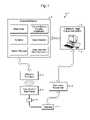
- FIG. 1provides a general system diagram showing an ultrasound system.
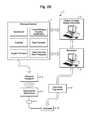
- FIGS. 2A , 2 B, and 2 Cillustrate various embodiments of the present system with an attached workstation.
- FIG. 3is an example of tabular data that an embodiment may display.
- FIG. 4provides a flowchart illustrating a procedure for determining a potential site for a pacemaker electrode implant and determining a configuration for the pacemaker.
- FIG. 5Aillustrates a measurement technique for calculating cross-sectional area of the output from the ventricle.
- FIG. 5Billustrates the basis of Doppler measurement used in an embodiment by delineating streamlined flow through a vessel, its profile through time and the basis of the time-integral area product showing volume of flow.
- FIG. 6illustrates a B-mode ultrasound image of a ventricle used in an embodiment.
- FIG. 7A-7Cillustrate the basis of ejection volume measurements according to various embodiments.
- Heart failureis a disease where the heart's main function, a pump for blood, is wearing down.
- the heart tissuecan absorb fluid, the left ventricle does not allow quick electrical conduction, becomes enlarged, does not contract well, and becomes less efficient at pumping blood.
- a measurement for the cardiac output (volume of ejected blood)is called the “ejection volume”.
- the efficiency of the heart as a pumpis called the “ejection fraction” or “EF”. EF is measured as the percentage of the blood volume contained in a ventricle which is pumped out (ejected) with each beat of the heart.
- a healthy, young heartwill have an EF greater than 90 (i.e., 90 percent of the ventricular blood is pumped with each heart beat); an older, sick heart in heart failure can have an EF less than 30 percent.
- Heart failureleads to an extremely diminished lifestyle, and, left untreated, can be a major cause of mortality.
- a new therapy to treat heart failureis bi-ventricular pacing, or “resynchronization” therapy, where both ventricles of the heart are paced with an implantable pulse generator, commonly known as an artificial pacemaker.
- Normal pacing for a slow heartis performed via an implanted electrode in the right ventricle.
- the conduction myofibers(Purkinje fibers) conduct the electrical pulse and the ventricles contract synchronously in an inward direction, resulting in blood being pumped efficiently from the heart.
- the left ventriclebecomes enlarged and conduction through the tissue of the left ventricular wall often becomes slow, so that the upper part of the left ventricle conducts as much as 200 to 250 milliseconds behind the apex area of the ventricles.
- an ideal site to place a pacing electrode in the left ventricleis in the area of slowest conduction, which can be a rather large area of the left ventricle, and may not always be the area that has the largest conduction.
- the problem facing physicians todayis to locate the optimal spot for the permanent fixation of the pacing electrode.
- the thrust of this inventionis to provide a method and device to optimize the site of the electrode.
- the term “site”generally refers to a specific physical or anatomical feature or location on or within the heart, regardless of where location or feature moves spatially over time.
- image locationgenerally refers to where an anatomical site is located within an ultrasound image at a specific time.
- An image locationmay be defined by 2-D pixel coordinates or by coordinates within an external frame of reference and the moment of time within a cardiac cycle.
- 3-D locationgenerally refers to where in a spatial coordinate system an anatomical site is located at a specific moment of time.
- a 3-D locationmay be located within a 3-D coordinate system (e.g., X,Y,Z) and the moment of time.
- pointmay be used interchangeably with “location”.
- the image location in a specific ultrasound imagemay correspond to a specific anatomical site, which in turn is located at a specific 3-D location at the moment corresponding to the image. Therefore, when describing a specific ultrasound image, the terms are often blurred, and a term sometimes may infer the physical site, the site's 3-D location at the moment of image capture, and/or the site's image location at the moment.
- positionand its related forms usually include both the concept of a 3-D location and the concept of a 3-D orientation.
- a standard pacemaker electrodeis commonly implanted at a site in the cardiac wall which achieves the lowest activation “threshold.” That is to say, the site for which the lowest voltage level is needed to excite the surrounding tissue to conduct synchronously the pacing signal from the electrode.
- the electrodehas been implanted based upon merely finding the site where the lowest activation voltage is needed to stimulate the muscle tissue reliably. The rationale for this is to minimize battery drain. Placing the pacemaker electrode in the optimal site is not an easy task. Ideally, a site is chosen which optimizes the EF. Finding a site with a low threshold, while desirable, is not as important as optimizing EF. Thus, the ability to not only visualize the motion of the left ventricular wall, but also measure EF, or some form of output of the heart, such as stroke volume or flow rate, is highly desirable during the implantation procedure.
- the various embodimentsuse ultrasound technology to provide this ability.
- the embodimentsprovide a toolset for using ultrasound imaging to evaluate and keep track of ventricular dysynchrony or cardiac ejection volume for each of multiple combinations of electrode sites and pacemaker configurations.
- the measurementsmay be performed either automatically or with interaction from the attending physician, who may pre-specify certain operating parameters or measurement criteria. Measurements and the associated specific combinations of electrode sites and pacemaker configurations may be stored, retrieved, listed, ranked, or analyzed by the physician to judge which combinations may be optimal.
- the various embodiments described hereinprovide tools to assist a clinician in configuring a pacemaker and selecting an optimal site for the pacemaker electrode.
- an ultrasound imaging system 1 suitable for measuring cardiac output of a patient's heart 2includes an ultrasound imaging transducer array 3 .
- the ultrasound imaging transducer array 3houses at least one ultrasonic transducer, which utilizes piezoelectric properties to generate acoustic signals from electrical signals in order to obtain ultrasound signals.
- the ultrasound transduceris of a type suitable for imaging the patient's heart and is used to obtain ultrasound signals associated with an area of the patent's heart in which cardiac output is to be measured.
- the transducer array 3may be embedded within an intravascular catheter.
- the signals received from the ultrasound transducer array 3are fed into an ultrasonic scanner unit 4 which contains the necessary digital or analog electronics to generate and process ultrasound signals from the at least one ultrasonic transducer array 3 to generate B-mode, M-mode, and/or Doppler representations of the patient's heart.
- These digital or analog electronicsinclude, for example, a beamformer, transmit/receive circuitry and amplification circuitry, a controller unit, a scan converter, a Doppler processor, and color flow as well as other processors.
- the systemincludes an associated ultrasound display and control console 5 that can generate and process the ultrasound signals in order to measure the cardiac output in the patient's heart and to measure the delay in the motion of a site on the cardiac wall with respect to the cardiac cycle.
- the console 5is configured to compute a measure of heart efficiency or functionality.
- the measuremay comprise the cardiac ejection volume estimated from the ultrasound data for the specific combination of pacemaker configuration and electrode site.
- an embodimentmay measure the dysynchrony delay between the motion of the septal and free walls of a ventricle, such as the left ventricle.
- An embodimentmay employ any other measurement of cardiac output or some combination of measurements of cardiac functionality, which result from the combination of pacemaker configuration and choice of electrode site. If more than one electrode is present, then the term “electrode site” herein may refer to the sites of all the available electrodes.
- any methodmay be used for estimating ejection volume or ejection fraction using ultrasound.
- One exemplary methodemploys Doppler ultrasound signals or spectral Doppler signals.
- the Doppler signalsthe boundaries of which can be either demarcated by the user, or automatically estimated by the system, along with the measure of the cross-sectional area through which such flow passes, which can again be either demarcated by the user, or automatically determined by the system, are utilized to calculate ejection volume of blood flow through the heart.
- V ejtAn alternative computation for V ejt is provided by Eq. 1b, which is amenable to M-mode ultrasound images of the heart obtained at discrete imaging intervals ⁇ t as illustrated in FIG. 7A .
- dimensional measurements of the vessel diameter obtained from M-mode imagesare used to estimate ejection volume.
- V ejtejection volume or stroke volume
- a simple closed surface geometrical modelmay be constructed.
- the location coordinates of cardiac wall sitesmay be obtained, for example, from the image planes of multiple ultrasound transducer arrays or from a 3-D ultrasound system.
- the multiple transducer arraysmay be intravascular, external to the heart, or both. If the 3-D coordinates of a dozen or so well distributed speckle points at a specific moment in the cardiac cycle can be measured thereby, for instance, a polyhedron, with those points as its vertices, can be constructed. Then the volume of the polyhedron would approximate the volume of the cardiac chamber, where the volume of the polyhedron is readily computed by known methods.
- a smoothly curved surface through the locations of cardiac wall sitesmay be constructed using known computer graphics methods. Then the volume contained by that surface may be an even better approximation of the volume of the cardiac chamber. Approximating such a polyhedral or curved surface for 3-D locations measured at each of systole and diastole times in the cardiac cycle and calculating the difference between the volumes of those two surfaces may approximate the ejection volume.
- the ejection fractionmay be estimated by determining a best-fit affine linear transformation which maps the coordinates of the N sites at diastole to the coordinates of the same N sites at systole.
- the transformationmay be two-dimensional if the N sites are all in one plane or may be three-dimensional if the N sites can be obtained in multiple planes.
- the best-fit linear transformationmay be determined, for example, using the well-known least-squares method and may be represented by a homogeneous matrix M, as is common practice in computer graphics.
- the ejection fraction F ejtmay be approximated as the square root of the product of the eigenvalues of M T M.
- the ejection fraction F ejtmay be approximated by the product of the eigenvalues of M T M, assuming that the longitudinal dimension of the cardiac cavity remains fairly constant.
- Nmust be at least 3 for non-collinear sites in a plane.
- Nmust be at least 4 for non-coplanar sites. Smaller inaccuracy will generally result for larger values of N and for wall sites which are distributed around the cardiac chamber.
- Another example of a method for estimating ejection volumeis to use an M-mode ultrasound image to measure the minimum (systolic) diameter D S and maximum (diastoic) diameter D D of a ventricle over the cardiac cycle.
- FIG. 6is a simplified drawing of a B-mode image with an M-mode cursor line.
- FIG. 7Aprovides a simplified example of an M-mode display corresponding to the cursor line of FIG. 6 .
- FIG. 7Ashows the diastolic wall-to-wall diameter 44 and systolic wall-to-wall diameter 43 .
- An example of a method for estimating dysynchrony delay within a ventriclealso involves an M-mode display.
- Time axis calipers for the M-mode displaycan measure the time delay between the motion of two ventricular wall sites, one on the septal wall and one on the free wall.
- Another example, using an ultrasound B-mode display,is U.S. patent application Ser. No. 11/428,517, which is incorporated entirely herein by reference and which tracks the phased, regional motion of images of sites on the ventricular wall.
- An embodiment which estimates the ejection volume or ejection fraction over a single cardiac cyclecan be further enhanced by averaging the per-cycle stroke volume or the per-cycle ejection fraction over multiple cycles. Besides providing a more representative mean value, measurements over a number of cycles allows the computation of the statistical variation or standard deviation. The standard deviation then provides an indication of the “error”, uncertainty, or untrustworthiness of the mean value.
- An embodimentincludes a console 5 that may exist as part of the ultrasound scanner system 4 .
- the system 4may utilize the Doppler processing capabilities of the host ultrasound scanner to estimate the cardiac ejection volume.
- the systemmay obtain a time-varying signal representative of the velocity of flow through a designated area of interest. Such area could include the inlet of the aorta from the left ventricle, or the valve in between.
- the systemmay then integrate the measured velocity of flow over the time of a cardiac cycle and integrate it across the area to compute the total ejection volume.
- the systemmay further express the total ejection volume as a fraction (percentage) of the maximum volume of the ventricular chamber from which the blood volume is ejected during a cardiac cycle.
- a cliniciancan use a pacemaker programmer 13 to set a pacemaker 12 to a specific configuration, such as setting the activation threshold voltage.
- a clinicianmay use a pacemaker programmer 13 to program the pacemaker 12 manually, but in an embodiment, the clinician directs the pacemaker programmer 13 to configure the pacemaker 12 by entering settings and commands into a computer 6 connected through an electronic interface to the pacemaker programmer 13 .
- the activation voltage of the pacemaker 12may be set by the pacemaker programmer 13 .
- a cardiac pacing electrode 11 driven by the pacemaker 12is positioned by the clinician at a specific site on the patient's heart 2 , and the pacemaker 12 is placed into operation.
- the heart 2is imaged by the intracardiac ultrasound transducer 3 coupled to the ultrasound imaging system 4 .
- FIGS. 2A , 2 B, and 2 CExample block diagrams of such embodiments are shown in FIGS. 2A , 2 B, and 2 C.
- Communication between or among the separate computer 6 , the ultrasound console 5 , and the ultrasound scanner 4can include processed ultrasound data, as well as video, audio, and/or any ECG signals in digital and/or analog format. The processing described herein can then be performed either partially or entirely on the separate computer 6 executing software instructions implementing the methods.
- An embodimentcombines the functionality of the separate computer 6 with the ultrasound console 5 into one hybrid unit, as shown in FIG. 1 .
- This embodimentmay also combine the software executing on computer 6 with the software executing on ultrasound console 5 .
- steps of the various method embodiments described herein as being performed on the computer 6may be performed on the ultrasound console 5
- steps described herein as being performed on the ultrasound console 5may alternatively be performed on the computer 6 .
- this specificationtreats the computer 6 of FIGS. 2A-2C as at least functionally, if not physically, separate from the ultrasound console 5 . That is, for simplified discussion, various cardiac measurements derived from the ultrasound images will be described as being performed on the ultrasound console 5 .
- the computer 6saves in memory at least one measurement of cardiac efficiency along with data concerning the corresponding combination of pacemaker configuration and the electrode site which produced the measurement or measurements.
- the configuration, the electrode site, and measurement information to be saved in memorymay be acquired automatically, obtained semi-automatically, or entered manually by the clinician.
- An embodimentfurther may retrieve from memory the measurement, the pacemaker configuration, and the electrode site of any of the saved combinations which have been tried.
- An embodimentcan provide a display of the saved information summarizing some or all of the tried and saved combinations and the corresponding cardiac efficiency measurements.
- the saved informationmay optionally be ranked or displayed according to at least one criterion.
- the saved informationmay be ranked and listed (1) in decreasing order of the amount of ejection fraction, (2) in increasing order of the activation voltage, (3) in increasing order of the least average septal-to-free-wall delay, or (4) a combinatorial blend of those values.
- An embodimentmay allow the ranking or display criterion to be specified by the clinician.
- An embodimentmay allow a user to delete saved information that is no longer of interest, such as one or more of the lower ranked combinations.
- An embodimentmay save or display the site of the pacing electrode in any form helpful to the clinician. Suitable forms include textual descriptions and graphical images.
- a nonlimiting example of such a displayincludes one or more ultrasound images on which the image locations of electrode sites are indicated with representative labels, icons or color-coded markers.
- Another example embodimentmay show a hybrid form, such as numerical data together with a connector or pointer on the image pointing to the corresponding image location of the site of the electrode on a saved ultrasound image.
- FIG. 3is an example for illustration purposes only of a tabular display of the information saved for several combinations of electrode site and activation voltage. In the example shown in FIG.
- each siteis simply referenced by a letter, where the letter also appears on a display of a corresponding saved image or images of the heart at the location of the electrode corresponding to the numerical data.
- the example in FIG. 3also includes the cardiac measurements corresponding to the heart without pacemaker activation.
- an electrode 11is positioned at a specific endocardial or epicardial site and is activated by a pacemaker 12 having a specific configuration.
- a pacemaker 12having a specific configuration.
- Various embodimentsassist a clinician in finding an optimal site and configuration that will reduce dysynchrony (time lag between the motion of the septal wall and the motion of the free wall) and/or increase cardiac ejection volume.
- it may be desirable to configure the pacemakerfor example, with the lowest reliable activation voltage to conserve battery life. Because dysynchrony, ejection volume, and activation voltage interact and do not necessarily correlate, a figure-of-merit evaluation function having such multiple factors as variables is desirable.
- the figure-of-merit evaluation function's coefficientsreflect the relative importance of each variable and can be tailored to various patient circumstances and conditions.
- F ( E,D,V )C E ⁇ E ⁇ C D ⁇ D ⁇ C V ⁇ V
- the cliniciancan repeatedly try attaching the electrode at various sites and try using various pacemaker configurations. Each new proposed combination may be based on previously measured dysynchrony, ejection volume or fraction, electrical activity, or other measurements.
- the cliniciancan use the figure-of-merit, or any chosen single measurement, to confirm or select one choice from the various combinations. Further, the clinician may use the figure-of-merit to compare the various tried combinations with a baseline figure-of-merit.
- the baseline figure-of-meritis computed from a measurement or measurements of cardiac functionality measured when the pacemaker is electrically inactive or when there is no electrode at a site. Such a baseline measurement may be taken before, between, or after the measurements are taken for which an electrode at a cardiac site is active.
- the configuration exhibiting the highest valueis most desirable. This is because the higher figure-of-merit is likely to reflect an optimal electrode site and/or configuration for a pacemaker.
- the figure-of-merit value computed from saved measurement informationmay be displayed along with the saved measurements, electrode sites, and pacemaker configurations in order to reveal which configuration will provide the best therapeutic result.
- the value of the figure-of-meritmay be displayed numerically, graphically, as a color code representing the value, or as some combination thereof.
- Function Fis unnecessary if only a single measure of cardiac functionality is consistently utilized to judge the optimal electrode site.
- the figure-of-merit functionmay be defined so that the optimal values of its independent variables produce a minimum resultant value of the function instead of a maximum value. Therefore, the description of various embodiments may use the term “optimal figure-of-merit value” for either a minimal value or maximal value, as appropriate, which corresponds to an optimal combination of electrode site, pacemaker setting and other configuration variables.
- An embodimentprovides permanent data storage for archiving one or more of the saved evaluated combinations of electrode site and pacemaker configurations along with the corresponding cardiac efficiency measurements and figures-of-merit.
- Such storagemay be a printed hardcopy or may be electronic data stored on a magnetic, electronic, or optical storage medium
- the computed figure-of-merit for the measurements corresponding to a specific site-configuration combinationmay be saved with the combination and measurement information.
- the figure-of-meritmay be dynamically recalculated each time its value must be displayed using stored factor data. Dynamic recalculation can allow all the figures-of-merit values to be updated immediately after a new figure-of-merit function is been defined or adjusted.
- the flowchart of FIG. 4provides an embodiment of a method for aiding a clinician in determining a potential optimal site for a pacemaker electrode and an optimal configuration for the pacemaker.
- the cliniciansets up and initializes the equipment, step 501 .
- the clinicianpositions a cardiac catheter, which includes an imaging ultrasound transducer array, so that the transducer array in conjunction with an ultrasound scanner unit yields an image of a portion of the patient's heart, step 502 .
- the clinicianselects a site on the heart (such as on the free wall of the left ventricle) and places a pacemaker or stimulator electrode at that site, step 503 .
- the clinicianconfigures the pacemaker or stimulator to which the electrode is connected, step 504 .
- the configuration parametersinclude at least the activation voltage level, but may contain other parameters relating to the activation pulse, such as the pulse shape or duration, the activation pulse frequency, and so forth.
- the configured pacemaker or stimulatoris placed into active operation using the located electrode. Any one or more known ultrasound techniques are used for estimating the ejection volume or ejection fraction, step 505 .
- the cardiac dysynchrony(time or phase delay between motions of the ventricular walls) is measured relative to the cardiac cycle in addition to or instead of the ejection volume, step 506 .
- a reference cardiac cyclemay be defined by an ECG signal (if available) or by the motion of a reference site on the cardiac wall.
- an embodimentmay provide a manual control or an automated detection of the delay T d between the ECG R wave and the maximum measured ventricular volume, and possibly also the delay between the ECG R wave and the minimum ventricular volume. This may be of particular significance for pacemaker configuration and electrode placement. This delay is illustrated in FIG. 7C .
- the computersaves an indication of the electrode site, the pacemaker configuration parameters, the ejection volume (or ejection fraction), the dysynchrony measurement, or other measures of cardiac efficiency, step 507 .
- the computermay also compute a figure-of-merit associated with the saved information, step 507 .
- the figure-of-meritis used or is applied to evaluate the degree of effectiveness provided by the pacemaker configuration and the electrode placement.
- the figure-of-meritmay be saved with the other saved information, or it may be dynamically recomputed as needed. (An example of a possible mathematical function for computing a figure of merit is provided herein.)
- the clinicianmay then move the electrode to another position on the heart and/or adjust the pacemaker or stimulator settings.
- the other electrode sites and/or other pacemaker/stimulator configurationsmay be evaluated by computing the figure-of-merit for those sites and those configurations, step 508 . This adjusting and evaluating continues until the clinician acquires sufficient information to make an evaluation.
- the computerdisplays the information in a graphical or tabular form, step 510 .
- the clinicianchooses a combination of an electrode site and a pacemaker configuration, presumably one which is associated with an optimal figure-of-merit, step 510 .
- the cliniciancan then implant the electrode at the chosen site and program the pacemaker to use the chosen configuration, step 511 .
- FIG. 4lists the steps of an embodiment in a specific order. Nevertheless, the steps need not be necessarily executed in the order described above and shown in FIG. 4 .
- the choosing of an electrode site or the programming of the pacemaker for activating the electrode at that sitemay be performed before the other, or they may be performed in parallel.
- the measurement of the ejection volume, the measurement of dysynchrony, or any other such measurementsmay be performed in any order, simultaneously, or in any combination.
- the figure-of-meritneed not be computed until all the trial site-configuration combinations have been measured, saved, and listed.
- baseline measurementsmay be taken when no electrode is embedded in the heart or no voltage is applied to an electrode, and the figure-of-merit may be applied also to those measurements. The baseline measurements may be acquired before or after or between measurements taken with an active electrode.
- step 510may further comprise steps of ranking the saved site-configuration combinations and the associated measurements, deleting those not of interest, evaluating the saved combinations with the figure-of-merit function, redefining the figure-of-merit function and re-evaluating the combinations using it, printing the saved combinations and measurements, and archiving the saved combinations and measurements.
- the above procedureis usable with the addition that the sites of all electrodes can be saved as one “site-assemblage” instead of a simple single site. Moving just one electrode of the assemblage to a new site may constitute a new “site-assemblage”.
- imaging and site motion trackingmay be used to image an unsteady pacing area or electrically malfunctioning area within the heart detected or located using ECG sensor data.
- U.S. Patent Provisional Application No. 60/795,912 entitled “Method For Simultaneous Bi-Atrial Mapping Of Atrial Fibrillation”which is incorporated herein by reference in its entirety, describes methods for locating malfunctioning areas of the heart using ECG data mapped on an anatomical model of the heart.
- the resulting site tracking or imagesmay enable the physician to more accurately locate and optimize the positions for pacing leads.
- motion tracking of the selected regionmay enable the physician to more accurately optimize the pacing timing and rhythm for the lead, both by measuring the lag before emplacement to estimate an appropriate timing parameter and by measuring the lag after pacing is initiated to confirm the region is responding as desired to the pacing stimulation.
- site tracking and ultrasound images of the heartmay be used to correct, correlate or otherwise improve the anatomical model used for displaying ECG data
- the ultrasound system, isolation box and temperature monitoring/cutoff circuitsmay be packaged as a combined unit which can be placed close to the patient and eliminate or shorten some of the cables required for a system comprised of separate components.
Landscapes
- Health & Medical Sciences (AREA)
- Life Sciences & Earth Sciences (AREA)
- Heart & Thoracic Surgery (AREA)
- Engineering & Computer Science (AREA)
- Veterinary Medicine (AREA)
- Biomedical Technology (AREA)
- Nuclear Medicine, Radiotherapy & Molecular Imaging (AREA)
- Radiology & Medical Imaging (AREA)
- Animal Behavior & Ethology (AREA)
- General Health & Medical Sciences (AREA)
- Public Health (AREA)
- Biophysics (AREA)
- Cardiology (AREA)
- Pathology (AREA)
- Physics & Mathematics (AREA)
- Medical Informatics (AREA)
- Molecular Biology (AREA)
- Surgery (AREA)
- Physiology (AREA)
- Hematology (AREA)
- Ultra Sonic Daignosis Equipment (AREA)
Abstract
Description
Vejt=A·∫(Vpeak(t)/2)dt Eq. 1a
where: Vejt=ejection volume;
- A=cross sectional area of flow; and
- Vpeak(t)=peak velocity at time t in the cardiac cycle.
FIG. 5A is simplified drawing of an example spectral Doppler ultrasound image, which depicts the peak velocity over time during a cardiac cycle.FIG. 5B graphically illustrates the basis for this formula.
where: Vejt=ejection volume or stroke volume;
- R(t)=one-half the distance between chamber walls in the M-mode image;
- L(t)=v(t) Δt=flow distance during time Δt at time t; and
- v(t)=mean flow velocity at time t.
FIG. 7B illustrates the above computation graphically on a simplified rendering of an M-mode image. The value of R(t) may be measured manually on the ultrasound image display using calipers built into the M-mode ultrasound display or may be determined automatically using a computer graphics edge detection algorithm. As used herein, “calipers” refers to maximum and minimum measurements or threshold settings, which may be illustrated on a graphical display with horizontal indicators at the maximum and minimum levels or brackets. Using calipers, the maximum and minimum measured distance measurements or image locations of sites on the ventricle wall can be indicated with the upper and lower bounds of the caliper, so that the displacement distance is indicated by the separation between the end locations of the caliper. Because ultrasound can measure R(t) and dt accurately, the error in Vejtmainly depends on the accuracy of the measurement of v(t).
EF=(DD2−DS2)/DD2
where: DD=diastolic wall-to-wall diameter; and
F(E,D,V)=CE·E−CD·D−CV·V
where:
- CE, CD, and CVare non-negative coefficients;
- E is the ejection fraction or is ejection volume (which is desirably high);
- D is the dysynchrony delay time or phase (which is desirably low); and
- V is the activation voltage (which is desirably low).
- The values of the coefficients CE, CD, and CVmay be determined from clinical experience and may depend on the age and health of the patient or on other factors. Assuming that larger values of function F signify more desirable combinations of E, D, and V, the value of function F should increase as the ejection fraction (or ejection volume) E increases. The value of function F should decrease as the dysynchrony delay D decreases, where D may be a time lag in milliseconds. The activation voltage V may be less important, but normally should be low, if ejection volume and dysynchrony are reliably maintained. That is, F should increase as V decreases. The evaluation function F yields a single figure of merit which relates the variables. The relative magnitudes of the coefficients reflect the relative importance of each argument E, D, and V. An embodiment allows a clinician to optionally change the values of the coefficients based on personal experience, on the characteristics of the cardiac patient or intended clinical use for the figure-of-merit.
Claims (21)
F(E,D,V)=CE·E−CD·D−CV·V
F(E,D,V)=CE·E−CD·D−CV·V
Priority Applications (1)
| Application Number | Priority Date | Filing Date | Title |
|---|---|---|---|
| US11/610,924US8187190B2 (en) | 2006-12-14 | 2006-12-14 | Method and system for configuration of a pacemaker and for placement of pacemaker electrodes |
Applications Claiming Priority (1)
| Application Number | Priority Date | Filing Date | Title |
|---|---|---|---|
| US11/610,924US8187190B2 (en) | 2006-12-14 | 2006-12-14 | Method and system for configuration of a pacemaker and for placement of pacemaker electrodes |
Publications (2)
| Publication Number | Publication Date |
|---|---|
| US20080146928A1 US20080146928A1 (en) | 2008-06-19 |
| US8187190B2true US8187190B2 (en) | 2012-05-29 |
Family
ID=39528348
Family Applications (1)
| Application Number | Title | Priority Date | Filing Date |
|---|---|---|---|
| US11/610,924Expired - Fee RelatedUS8187190B2 (en) | 2006-12-14 | 2006-12-14 | Method and system for configuration of a pacemaker and for placement of pacemaker electrodes |
Country Status (1)
| Country | Link |
|---|---|
| US (1) | US8187190B2 (en) |
Families Citing this family (14)
| Publication number | Priority date | Publication date | Assignee | Title |
|---|---|---|---|---|
| US7907997B2 (en)* | 2005-05-11 | 2011-03-15 | Cardiac Pacemakers, Inc. | Enhancements to the detection of pulmonary edema when using transthoracic impedance |
| US9968256B2 (en) | 2007-03-08 | 2018-05-15 | Sync-Rx Ltd. | Automatic identification of a tool |
| WO2008107905A2 (en) | 2007-03-08 | 2008-09-12 | Sync-Rx, Ltd. | Imaging and tools for use with moving organs |
| US10716528B2 (en) | 2007-03-08 | 2020-07-21 | Sync-Rx, Ltd. | Automatic display of previously-acquired endoluminal images |
| US11197651B2 (en) | 2007-03-08 | 2021-12-14 | Sync-Rx, Ltd. | Identification and presentation of device-to-vessel relative motion |
| US11064964B2 (en) | 2007-03-08 | 2021-07-20 | Sync-Rx, Ltd | Determining a characteristic of a lumen by measuring velocity of a contrast agent |
| US8781193B2 (en) | 2007-03-08 | 2014-07-15 | Sync-Rx, Ltd. | Automatic quantitative vessel analysis |
| US9974509B2 (en) | 2008-11-18 | 2018-05-22 | Sync-Rx Ltd. | Image super enhancement |
| US10362962B2 (en) | 2008-11-18 | 2019-07-30 | Synx-Rx, Ltd. | Accounting for skipped imaging locations during movement of an endoluminal imaging probe |
| US11064903B2 (en)* | 2008-11-18 | 2021-07-20 | Sync-Rx, Ltd | Apparatus and methods for mapping a sequence of images to a roadmap image |
| EP2415401A4 (en)* | 2009-03-31 | 2017-04-19 | Hitachi, Ltd. | Medical image diagnosis device and volume calculating method |
| WO2011040842A1 (en)* | 2009-09-30 | 2011-04-07 | St. Jude Medical Ab | Heart stimulating device with selecting optimal electrode configuration |
| EP2629845B1 (en)* | 2010-10-21 | 2016-09-07 | Boston Scientific Neuromodulation Corporation | System for introducing a tissue stimulation lead into a patient using real-time coupling efficiency measurements |
| EP2863802B1 (en) | 2012-06-26 | 2020-11-04 | Sync-RX, Ltd. | Flow-related image processing in luminal organs |
Citations (114)
| Publication number | Priority date | Publication date | Assignee | Title |
|---|---|---|---|---|
| US4161121A (en) | 1976-04-05 | 1979-07-17 | Varian Associates, Inc. | Ultrasonic imaging system |
| US4241610A (en) | 1979-02-05 | 1980-12-30 | Varian Associates, Inc. | Ultrasonic imaging system utilizing dynamic and pseudo-dynamic focusing |
| US4462408A (en) | 1982-05-17 | 1984-07-31 | Advanced Technology Laboratories, Inc. | Ultrasonic endoscope having elongated array mounted in manner allowing it to remain flexible |
| US4519260A (en) | 1982-02-18 | 1985-05-28 | The Board Of Trustees Of The Leland Stanford Junior University | Ultrasonic transducers and applications thereof |
| US4576177A (en) | 1983-02-18 | 1986-03-18 | Webster Wilton W Jr | Catheter for removing arteriosclerotic plaque |
| US4605009A (en) | 1983-04-06 | 1986-08-12 | Universite Francois Rabelais | Ultrasonic sweep echography and display endoscopic probe |
| US4841977A (en) | 1987-05-26 | 1989-06-27 | Inter Therapy, Inc. | Ultra-thin acoustic transducer and balloon catheter using same in imaging array subassembly |
| US4890268A (en) | 1988-12-27 | 1989-12-26 | General Electric Company | Two-dimensional phased array of ultrasonic transducers |
| US4917097A (en) | 1987-10-27 | 1990-04-17 | Endosonics Corporation | Apparatus and method for imaging small cavities |
| US4951677A (en) | 1988-03-21 | 1990-08-28 | Prutech Research And Development Partnership Ii | Acoustic imaging catheter and the like |
| US5002059A (en) | 1989-07-26 | 1991-03-26 | Boston Scientific Corporation | Tip filled ultrasound catheter |
| US5090956A (en) | 1983-10-31 | 1992-02-25 | Catheter Research, Inc. | Catheter with memory element-controlled steering |
| US5105819A (en) | 1988-09-01 | 1992-04-21 | Kon-Tron Elektronik AG | Ultrasound endoscope device |
| US5152294A (en) | 1989-12-14 | 1992-10-06 | Aloka Co., Ltd. | Three-dimensional ultrasonic scanner |
| US5158087A (en) | 1992-01-31 | 1992-10-27 | Hewlett-Packard Company | Differential temperature measurement for ultrasound transducer thermal control |
| US5170793A (en) | 1990-02-07 | 1992-12-15 | Kabushiki Kaisha Toshiba | Ultrasonic probe |
| US5195968A (en) | 1990-02-02 | 1993-03-23 | Ingemar Lundquist | Catheter steering mechanism |
| US5211169A (en) | 1990-11-08 | 1993-05-18 | Prism Imaging, Inc. | Blood pool imaging and analysis technique using ultrasound |
| US5254088A (en) | 1990-02-02 | 1993-10-19 | Ep Technologies, Inc. | Catheter steering mechanism |
| US5279559A (en) | 1992-03-06 | 1994-01-18 | Aai Corporation | Remote steering system for medical catheter |
| US5287753A (en) | 1992-05-02 | 1994-02-22 | Advanced Technology Laboratories, Inc. | Continuous display of peak and mean blood flow velocities |
| US5307816A (en) | 1991-08-21 | 1994-05-03 | Kabushiki Kaisha Toshiba | Thrombus resolving treatment apparatus |
| US5309914A (en) | 1991-04-17 | 1994-05-10 | Kabushiki Kaisha Toshiba | Ultrasonic imaging apparatus |
| US5325860A (en) | 1991-11-08 | 1994-07-05 | Mayo Foundation For Medical Education And Research | Ultrasonic and interventional catheter and method |
| US5345938A (en) | 1991-09-30 | 1994-09-13 | Kabushiki Kaisha Toshiba | Diagnostic apparatus for circulatory systems |
| US5357550A (en) | 1991-09-09 | 1994-10-18 | Kabushiki Kaisha Toshiba | Apparatus for diagnosing vascular systems in organism |
| US5358478A (en) | 1990-02-02 | 1994-10-25 | Ep Technologies, Inc. | Catheter steering assembly providing asymmetric left and right curve configurations |
| US5364351A (en) | 1992-11-13 | 1994-11-15 | Ep Technologies, Inc. | Catheter steering mechanism |
| US5372138A (en) | 1988-03-21 | 1994-12-13 | Boston Scientific Corporation | Acousting imaging catheters and the like |
| US5385148A (en) | 1993-07-30 | 1995-01-31 | The Regents Of The University Of California | Cardiac imaging and ablation catheter |
| US5438997A (en) | 1991-03-13 | 1995-08-08 | Sieben; Wayne | Intravascular imaging apparatus and methods for use and manufacture |
| US5456258A (en) | 1993-12-20 | 1995-10-10 | Fuji Photo Optical Co., Ltd. | Catheter type ultrasound probe |
| US5470350A (en) | 1993-04-02 | 1995-11-28 | Siemens Aktiengesellschaft | System for the treatment of pathological tissue having a catheter with a pressure sensor |
| US5499630A (en) | 1993-11-22 | 1996-03-19 | Kabushiki Kaisha Toshiba | Catheter type ultrasound probe |
| US5515856A (en) | 1994-08-30 | 1996-05-14 | Vingmed Sound A/S | Method for generating anatomical M-mode displays |
| US5515853A (en) | 1995-03-28 | 1996-05-14 | Sonometrics Corporation | Three-dimensional digital ultrasound tracking system |
| US5560362A (en) | 1994-06-13 | 1996-10-01 | Acuson Corporation | Active thermal control of ultrasound transducers |
| US5588432A (en) | 1988-03-21 | 1996-12-31 | Boston Scientific Corporation | Catheters for imaging, sensing electrical potentials, and ablating tissue |
| US5622174A (en) | 1992-10-02 | 1997-04-22 | Kabushiki Kaisha Toshiba | Ultrasonic diagnosis apparatus and image displaying system |
| US5634465A (en) | 1995-06-09 | 1997-06-03 | Advanced Technology Laboratories, Inc. | Continuous display of cardiac blood flow information |
| US5662116A (en) | 1995-09-12 | 1997-09-02 | Fuji Photo Optical Co., Ltd. | Multi-plane electronic scan ultrasound probe |
| US5697965A (en) | 1996-04-01 | 1997-12-16 | Procath Corporation | Method of making an atrial defibrillation catheter |
| US5699805A (en) | 1996-06-20 | 1997-12-23 | Mayo Foundation For Medical Education And Research | Longitudinal multiplane ultrasound transducer underfluid catheter system |
| US5704361A (en) | 1991-11-08 | 1998-01-06 | Mayo Foundation For Medical Education And Research | Volumetric image ultrasound transducer underfluid catheter system |
| US5713363A (en) | 1991-11-08 | 1998-02-03 | Mayo Foundation For Medical Education And Research | Ultrasound catheter and method for imaging and hemodynamic monitoring |
| US5715817A (en) | 1993-06-29 | 1998-02-10 | C.R. Bard, Inc. | Bidirectional steering catheter |
| US5722403A (en) | 1996-10-28 | 1998-03-03 | Ep Technologies, Inc. | Systems and methods using a porous electrode for ablating and visualizing interior tissue regions |
| US5749364A (en) | 1996-06-21 | 1998-05-12 | Acuson Corporation | Method and apparatus for mapping pressure and tissue properties |
| US5788636A (en) | 1997-02-25 | 1998-08-04 | Acuson Corporation | Method and system for forming an ultrasound image of a tissue while simultaneously ablating the tissue |
| US5795299A (en) | 1997-01-31 | 1998-08-18 | Acuson Corporation | Ultrasonic transducer assembly with extended flexible circuits |
| US5797848A (en) | 1997-01-31 | 1998-08-25 | Acuson Corporation | Ultrasonic transducer assembly with improved electrical interface |
| US5797396A (en)* | 1995-06-07 | 1998-08-25 | University Of Florida Research Foundation | Automated method for digital image quantitation |
| US5800356A (en) | 1997-05-29 | 1998-09-01 | Advanced Technology Laboratories, Inc. | Ultrasonic diagnostic imaging system with doppler assisted tracking of tissue motion |
| US5807324A (en) | 1996-04-01 | 1998-09-15 | Procath Corporation | Steerable catheter |
| US5833624A (en) | 1996-04-30 | 1998-11-10 | Medtronic, Inc. | Method for using continuous cardiac output monitor |
| US5846205A (en) | 1997-01-31 | 1998-12-08 | Acuson Corporation | Catheter-mounted, phased-array ultrasound transducer with improved imaging |
| US5888577A (en) | 1997-06-30 | 1999-03-30 | Procath Corporation | Method for forming an electrophysiology catheter |
| US5891088A (en) | 1990-02-02 | 1999-04-06 | Ep Technologies, Inc. | Catheter steering assembly providing asymmetric left and right curve configurations |
| US5906579A (en) | 1996-08-16 | 1999-05-25 | Smith & Nephew Endoscopy, Inc. | Through-wall catheter steering and positioning |
| US5916168A (en) | 1997-05-29 | 1999-06-29 | Advanced Technology Laboratories, Inc. | Three dimensional M-mode ultrasonic diagnostic imaging system |
| US5921978A (en) | 1997-06-20 | 1999-07-13 | Ep Technologies, Inc. | Catheter tip steering plane marker |
| US5928276A (en) | 1998-06-11 | 1999-07-27 | Griffin, Iii; Joseph C. | Combined cable and electrophysiology catheters |
| US5931863A (en) | 1997-12-22 | 1999-08-03 | Procath Corporation | Electrophysiology catheter |
| US5935102A (en) | 1993-05-14 | 1999-08-10 | C. R. Bard | Steerable electrode catheter |
| US5938616A (en) | 1997-01-31 | 1999-08-17 | Acuson Corporation | Steering mechanism and steering line for a catheter-mounted ultrasonic transducer |
| US5954654A (en) | 1997-01-31 | 1999-09-21 | Acuson Corporation | Steering mechanism and steering line for a catheter-mounted ultrasonic transducer |
| US6013072A (en) | 1997-07-09 | 2000-01-11 | Intraluminal Therapeutics, Inc. | Systems and methods for steering a catheter through body tissue |
| US6033378A (en) | 1990-02-02 | 2000-03-07 | Ep Technologies, Inc. | Catheter steering mechanism |
| US6144870A (en) | 1996-10-21 | 2000-11-07 | Procath Corporation | Catheter with improved electrodes and method of fabrication |
| US6171248B1 (en) | 1997-02-27 | 2001-01-09 | Acuson Corporation | Ultrasonic probe, system and method for two-dimensional imaging or three-dimensional reconstruction |
| US6190353B1 (en) | 1995-10-13 | 2001-02-20 | Transvascular, Inc. | Methods and apparatus for bypassing arterial obstructions and/or performing other transvascular procedures |
| US6210333B1 (en) | 1999-10-12 | 2001-04-03 | Acuson Corporation | Medical diagnostic ultrasound system and method for automated triggered intervals |
| US6224556B1 (en) | 1998-11-25 | 2001-05-01 | Acuson Corporation | Diagnostic medical ultrasound system and method for using a sparse array |
| US6228028B1 (en) | 1996-11-07 | 2001-05-08 | Tomtec Imaging Systems Gmbh | Method and apparatus for ultrasound image reconstruction |
| US6261246B1 (en) | 1997-09-29 | 2001-07-17 | Scimed Life Systems, Inc. | Intravascular imaging guidewire |
| US6285898B1 (en)* | 1993-07-20 | 2001-09-04 | Biosense, Inc. | Cardiac electromechanics |
| US6293943B1 (en) | 1995-06-07 | 2001-09-25 | Ep Technologies, Inc. | Tissue heating and ablation systems and methods which predict maximum tissue temperature |
| US6306097B1 (en) | 1999-06-17 | 2001-10-23 | Acuson Corporation | Ultrasound imaging catheter guiding assembly with catheter working port |
| US6310828B1 (en) | 1997-07-18 | 2001-10-30 | Tomtec Imaging Systems Gmbh | Method and device for sensing ultrasound images |
| US6360027B1 (en) | 1996-02-29 | 2002-03-19 | Acuson Corporation | Multiple ultrasound image registration system, method and transducer |
| US6358208B1 (en) | 1998-11-21 | 2002-03-19 | Philipp Lang | Assessment of cardiovascular performance using ultrasound methods and devices that interrogate interstitial fluid |
| US6368275B1 (en) | 1999-10-07 | 2002-04-09 | Acuson Corporation | Method and apparatus for diagnostic medical information gathering, hyperthermia treatment, or directed gene therapy |
| US6385489B1 (en) | 1998-09-25 | 2002-05-07 | Ep Medsystems, Inc. | Triple array defibrillation catheter and method of using the same |
| US6398731B1 (en) | 1997-07-25 | 2002-06-04 | Tomtec Imaging Systems Gmbh | Method for recording ultrasound images of moving objects |
| US6423002B1 (en) | 1999-06-24 | 2002-07-23 | Acuson Corporation | Intra-operative diagnostic ultrasound multiple-array transducer probe and optional surgical tool |
| US6440488B2 (en) | 1999-12-03 | 2002-08-27 | Ep Medsystems, Inc. | Flexible electrode catheter and process for manufacturing the same |
| US6443894B1 (en) | 1999-09-29 | 2002-09-03 | Acuson Corporation | Medical diagnostic ultrasound system and method for mapping surface data for three dimensional imaging |
| US6475148B1 (en) | 2000-10-25 | 2002-11-05 | Acuson Corporation | Medical diagnostic ultrasound-aided drug delivery system and method |
| US6475149B1 (en) | 2001-09-21 | 2002-11-05 | Acuson Corporation | Border detection method and system |
| US6482161B1 (en) | 2000-06-29 | 2002-11-19 | Acuson Corporation | Medical diagnostic ultrasound system and method for vessel structure analysis |
| US6491633B1 (en) | 2000-03-10 | 2002-12-10 | Acuson Corporation | Medical diagnostic ultrasound system and method for contrast agent image beamformation |
| US6503202B1 (en) | 2000-06-29 | 2003-01-07 | Acuson Corp. | Medical diagnostic ultrasound system and method for flow analysis |
| US6517488B1 (en) | 2000-06-29 | 2003-02-11 | Acuson Corporation | Medical diagnostic ultrasound system and method for identifying constrictions |
| US6527717B1 (en) | 2000-03-10 | 2003-03-04 | Acuson Corporation | Tissue motion analysis medical diagnostic ultrasound system and method |
| US6527718B1 (en)* | 1999-08-20 | 2003-03-04 | Brian G Connor | Ultrasound system for continuous imaging and delivery of an encapsulated agent |
| US20030045796A1 (en) | 2001-08-31 | 2003-03-06 | Friedman Zvi M. | Ultrasonic monitoring system and method |
| US6532378B2 (en) | 2000-01-14 | 2003-03-11 | Ep Medsystems, Inc. | Pulmonary artery catheter for left and right atrial recording |
| US6554770B1 (en) | 1998-11-20 | 2003-04-29 | Acuson Corporation | Medical diagnostic ultrasound imaging methods for extended field of view |
| US6589182B1 (en) | 2001-02-12 | 2003-07-08 | Acuson Corporation | Medical diagnostic ultrasound catheter with first and second tip portions |
| US6605043B1 (en) | 1998-11-19 | 2003-08-12 | Acuson Corp. | Diagnostic medical ultrasound systems and transducers utilizing micro-mechanical components |
| US6607528B1 (en) | 1999-06-22 | 2003-08-19 | Senorx, Inc. | Shapeable electrosurgical scalpel |
| US6607488B1 (en) | 2000-03-02 | 2003-08-19 | Acuson Corporation | Medical diagnostic ultrasound system and method for scanning plane orientation |
| US6612992B1 (en) | 2000-03-02 | 2003-09-02 | Acuson Corp | Medical diagnostic ultrasound catheter and method for position determination |
| US6645147B1 (en) | 1998-11-25 | 2003-11-11 | Acuson Corporation | Diagnostic medical ultrasound image and system for contrast agent imaging |
| US6648875B2 (en) | 2001-05-04 | 2003-11-18 | Cardiac Pacemakers, Inc. | Means for maintaining tension on a steering tendon in a steerable catheter |
| US6709396B2 (en) | 2002-07-17 | 2004-03-23 | Vermon | Ultrasound array transducer for catheter use |
| US20040097805A1 (en) | 2002-11-19 | 2004-05-20 | Laurent Verard | Navigation system for cardiac therapies |
| US20040249282A1 (en) | 2003-06-09 | 2004-12-09 | Bjorn Olstad | System and method for extracting information based on ultrasound-located landmarks |
| US6908434B1 (en) | 2002-01-16 | 2005-06-21 | Ep Medsystems, Inc. | Ultrasound imaging catheter isolation system with temperature sensor |
| US6923768B2 (en) | 2002-03-11 | 2005-08-02 | Siemens Aktiengesellschaft | Method and apparatus for acquiring and displaying a medical instrument introduced into a cavity organ of a patient to be examined or treated |
| US20050203395A1 (en) | 2004-02-05 | 2005-09-15 | Siemens Medical Solutions Usa, Inc. | Motion analysis improvements for medical diagnostic ultrasound |
| US20050203390A1 (en) | 1999-08-23 | 2005-09-15 | Hans Torp | Method and apparatus for providing real-time calculation and display of tissue deformation in ultrasound imaging |
| US7097619B2 (en) | 2002-09-03 | 2006-08-29 | Siemens Medical Solutions Usa, Inc. | Elevation beam pattern variation for ultrasound imaging |
| US20090131788A1 (en) | 2006-05-25 | 2009-05-21 | Koninklijke Philips Electronics, N.V. | Quantification and display of cardiac chamber wall thickening |
Family Cites Families (2)
| Publication number | Priority date | Publication date | Assignee | Title |
|---|---|---|---|---|
| US5158067A (en)* | 1991-10-21 | 1992-10-27 | Dutro Company | Wok adapted portable food cooker |
| US5891068A (en)* | 1997-03-28 | 1999-04-06 | Kenney; John P. | Orthotic device for treating contractures due to immobility |
- 2006
- 2006-12-14USUS11/610,924patent/US8187190B2/ennot_activeExpired - Fee Related
Patent Citations (127)
| Publication number | Priority date | Publication date | Assignee | Title |
|---|---|---|---|---|
| US4161121A (en) | 1976-04-05 | 1979-07-17 | Varian Associates, Inc. | Ultrasonic imaging system |
| US4241610A (en) | 1979-02-05 | 1980-12-30 | Varian Associates, Inc. | Ultrasonic imaging system utilizing dynamic and pseudo-dynamic focusing |
| US4519260A (en) | 1982-02-18 | 1985-05-28 | The Board Of Trustees Of The Leland Stanford Junior University | Ultrasonic transducers and applications thereof |
| US4462408A (en) | 1982-05-17 | 1984-07-31 | Advanced Technology Laboratories, Inc. | Ultrasonic endoscope having elongated array mounted in manner allowing it to remain flexible |
| US4576177A (en) | 1983-02-18 | 1986-03-18 | Webster Wilton W Jr | Catheter for removing arteriosclerotic plaque |
| US4605009A (en) | 1983-04-06 | 1986-08-12 | Universite Francois Rabelais | Ultrasonic sweep echography and display endoscopic probe |
| US5090956A (en) | 1983-10-31 | 1992-02-25 | Catheter Research, Inc. | Catheter with memory element-controlled steering |
| US4841977A (en) | 1987-05-26 | 1989-06-27 | Inter Therapy, Inc. | Ultra-thin acoustic transducer and balloon catheter using same in imaging array subassembly |
| US4917097A (en) | 1987-10-27 | 1990-04-17 | Endosonics Corporation | Apparatus and method for imaging small cavities |
| US4951677A (en) | 1988-03-21 | 1990-08-28 | Prutech Research And Development Partnership Ii | Acoustic imaging catheter and the like |
| US5588432A (en) | 1988-03-21 | 1996-12-31 | Boston Scientific Corporation | Catheters for imaging, sensing electrical potentials, and ablating tissue |
| US5372138A (en) | 1988-03-21 | 1994-12-13 | Boston Scientific Corporation | Acousting imaging catheters and the like |
| US5105819A (en) | 1988-09-01 | 1992-04-21 | Kon-Tron Elektronik AG | Ultrasound endoscope device |
| US4890268A (en) | 1988-12-27 | 1989-12-26 | General Electric Company | Two-dimensional phased array of ultrasonic transducers |
| US5002059A (en) | 1989-07-26 | 1991-03-26 | Boston Scientific Corporation | Tip filled ultrasound catheter |
| US5152294A (en) | 1989-12-14 | 1992-10-06 | Aloka Co., Ltd. | Three-dimensional ultrasonic scanner |
| US6033378A (en) | 1990-02-02 | 2000-03-07 | Ep Technologies, Inc. | Catheter steering mechanism |
| US5195968A (en) | 1990-02-02 | 1993-03-23 | Ingemar Lundquist | Catheter steering mechanism |
| US5254088A (en) | 1990-02-02 | 1993-10-19 | Ep Technologies, Inc. | Catheter steering mechanism |
| US5531686A (en) | 1990-02-02 | 1996-07-02 | Ep Technologies, Inc. | Catheter steering mechanism |
| US6485455B1 (en) | 1990-02-02 | 2002-11-26 | Ep Technologies, Inc. | Catheter steering assembly providing asymmetric left and right curve configurations |
| US5891088A (en) | 1990-02-02 | 1999-04-06 | Ep Technologies, Inc. | Catheter steering assembly providing asymmetric left and right curve configurations |
| US5358478A (en) | 1990-02-02 | 1994-10-25 | Ep Technologies, Inc. | Catheter steering assembly providing asymmetric left and right curve configurations |
| US5395327A (en) | 1990-02-02 | 1995-03-07 | Ep Technologies, Inc. | Catheter steering mechanism |
| US5336182A (en) | 1990-02-02 | 1994-08-09 | Ep Technologies, Inc. | Catheter steering mechanism |
| US5170793A (en) | 1990-02-07 | 1992-12-15 | Kabushiki Kaisha Toshiba | Ultrasonic probe |
| US5211169A (en) | 1990-11-08 | 1993-05-18 | Prism Imaging, Inc. | Blood pool imaging and analysis technique using ultrasound |
| US5438997A (en) | 1991-03-13 | 1995-08-08 | Sieben; Wayne | Intravascular imaging apparatus and methods for use and manufacture |
| US5309914A (en) | 1991-04-17 | 1994-05-10 | Kabushiki Kaisha Toshiba | Ultrasonic imaging apparatus |
| US5307816A (en) | 1991-08-21 | 1994-05-03 | Kabushiki Kaisha Toshiba | Thrombus resolving treatment apparatus |
| US5357550A (en) | 1991-09-09 | 1994-10-18 | Kabushiki Kaisha Toshiba | Apparatus for diagnosing vascular systems in organism |
| US5345938A (en) | 1991-09-30 | 1994-09-13 | Kabushiki Kaisha Toshiba | Diagnostic apparatus for circulatory systems |
| US6039693A (en) | 1991-11-08 | 2000-03-21 | Mayo Foundation For Medical Education And Research | Volumetric image ultrasound transducer underfluid catheter system |
| US5345940A (en) | 1991-11-08 | 1994-09-13 | Mayo Foundation For Medical Education And Research | Transvascular ultrasound hemodynamic and interventional catheter and method |
| US5325860A (en) | 1991-11-08 | 1994-07-05 | Mayo Foundation For Medical Education And Research | Ultrasonic and interventional catheter and method |
| US6306096B1 (en) | 1991-11-08 | 2001-10-23 | Mayo Foundation For Medical Education And Research | Volumetric image ultrasound transducer underfluid catheter system |
| US5713363A (en) | 1991-11-08 | 1998-02-03 | Mayo Foundation For Medical Education And Research | Ultrasound catheter and method for imaging and hemodynamic monitoring |
| US5704361A (en) | 1991-11-08 | 1998-01-06 | Mayo Foundation For Medical Education And Research | Volumetric image ultrasound transducer underfluid catheter system |
| US5158087A (en) | 1992-01-31 | 1992-10-27 | Hewlett-Packard Company | Differential temperature measurement for ultrasound transducer thermal control |
| US5279559A (en) | 1992-03-06 | 1994-01-18 | Aai Corporation | Remote steering system for medical catheter |
| US5287753A (en) | 1992-05-02 | 1994-02-22 | Advanced Technology Laboratories, Inc. | Continuous display of peak and mean blood flow velocities |
| US5701897A (en) | 1992-10-02 | 1997-12-30 | Kabushiki Kaisha Toshiba | Ultrasonic diagnosis apparatus and image displaying system |
| US5622174A (en) | 1992-10-02 | 1997-04-22 | Kabushiki Kaisha Toshiba | Ultrasonic diagnosis apparatus and image displaying system |
| US5456664A (en) | 1992-11-13 | 1995-10-10 | Ep Technologies, Inc. | Catheter steering mechanism |
| US5364351A (en) | 1992-11-13 | 1994-11-15 | Ep Technologies, Inc. | Catheter steering mechanism |
| US5470350A (en) | 1993-04-02 | 1995-11-28 | Siemens Aktiengesellschaft | System for the treatment of pathological tissue having a catheter with a pressure sensor |
| US5935102A (en) | 1993-05-14 | 1999-08-10 | C. R. Bard | Steerable electrode catheter |
| US5715817A (en) | 1993-06-29 | 1998-02-10 | C.R. Bard, Inc. | Bidirectional steering catheter |
| US6285898B1 (en)* | 1993-07-20 | 2001-09-04 | Biosense, Inc. | Cardiac electromechanics |
| US5385148A (en) | 1993-07-30 | 1995-01-31 | The Regents Of The University Of California | Cardiac imaging and ablation catheter |
| US5499630A (en) | 1993-11-22 | 1996-03-19 | Kabushiki Kaisha Toshiba | Catheter type ultrasound probe |
| US5456258A (en) | 1993-12-20 | 1995-10-10 | Fuji Photo Optical Co., Ltd. | Catheter type ultrasound probe |
| US5560362A (en) | 1994-06-13 | 1996-10-01 | Acuson Corporation | Active thermal control of ultrasound transducers |
| US5515856A (en) | 1994-08-30 | 1996-05-14 | Vingmed Sound A/S | Method for generating anatomical M-mode displays |
| US5515853A (en) | 1995-03-28 | 1996-05-14 | Sonometrics Corporation | Three-dimensional digital ultrasound tracking system |
| US5797396A (en)* | 1995-06-07 | 1998-08-25 | University Of Florida Research Foundation | Automated method for digital image quantitation |
| US6293943B1 (en) | 1995-06-07 | 2001-09-25 | Ep Technologies, Inc. | Tissue heating and ablation systems and methods which predict maximum tissue temperature |
| US5634465A (en) | 1995-06-09 | 1997-06-03 | Advanced Technology Laboratories, Inc. | Continuous display of cardiac blood flow information |
| US5662116A (en) | 1995-09-12 | 1997-09-02 | Fuji Photo Optical Co., Ltd. | Multi-plane electronic scan ultrasound probe |
| US6190353B1 (en) | 1995-10-13 | 2001-02-20 | Transvascular, Inc. | Methods and apparatus for bypassing arterial obstructions and/or performing other transvascular procedures |
| US6360027B1 (en) | 1996-02-29 | 2002-03-19 | Acuson Corporation | Multiple ultrasound image registration system, method and transducer |
| US5807324A (en) | 1996-04-01 | 1998-09-15 | Procath Corporation | Steerable catheter |
| US5697965A (en) | 1996-04-01 | 1997-12-16 | Procath Corporation | Method of making an atrial defibrillation catheter |
| US5833624A (en) | 1996-04-30 | 1998-11-10 | Medtronic, Inc. | Method for using continuous cardiac output monitor |
| US5699805A (en) | 1996-06-20 | 1997-12-23 | Mayo Foundation For Medical Education And Research | Longitudinal multiplane ultrasound transducer underfluid catheter system |
| US5749364A (en) | 1996-06-21 | 1998-05-12 | Acuson Corporation | Method and apparatus for mapping pressure and tissue properties |
| US5906579A (en) | 1996-08-16 | 1999-05-25 | Smith & Nephew Endoscopy, Inc. | Through-wall catheter steering and positioning |
| US6144870A (en) | 1996-10-21 | 2000-11-07 | Procath Corporation | Catheter with improved electrodes and method of fabrication |
| US5722403A (en) | 1996-10-28 | 1998-03-03 | Ep Technologies, Inc. | Systems and methods using a porous electrode for ablating and visualizing interior tissue regions |
| US6228028B1 (en) | 1996-11-07 | 2001-05-08 | Tomtec Imaging Systems Gmbh | Method and apparatus for ultrasound image reconstruction |
| US5846205A (en) | 1997-01-31 | 1998-12-08 | Acuson Corporation | Catheter-mounted, phased-array ultrasound transducer with improved imaging |
| US6228032B1 (en) | 1997-01-31 | 2001-05-08 | Acuson Corporation | Steering mechanism and steering line for a catheter-mounted ultrasonic transducer |
| US5954654A (en) | 1997-01-31 | 1999-09-21 | Acuson Corporation | Steering mechanism and steering line for a catheter-mounted ultrasonic transducer |
| US5938616A (en) | 1997-01-31 | 1999-08-17 | Acuson Corporation | Steering mechanism and steering line for a catheter-mounted ultrasonic transducer |
| US5795299A (en) | 1997-01-31 | 1998-08-18 | Acuson Corporation | Ultrasonic transducer assembly with extended flexible circuits |
| US5797848A (en) | 1997-01-31 | 1998-08-25 | Acuson Corporation | Ultrasonic transducer assembly with improved electrical interface |
| US5788636A (en) | 1997-02-25 | 1998-08-04 | Acuson Corporation | Method and system for forming an ultrasound image of a tissue while simultaneously ablating the tissue |
| US6171248B1 (en) | 1997-02-27 | 2001-01-09 | Acuson Corporation | Ultrasonic probe, system and method for two-dimensional imaging or three-dimensional reconstruction |
| US5916168A (en) | 1997-05-29 | 1999-06-29 | Advanced Technology Laboratories, Inc. | Three dimensional M-mode ultrasonic diagnostic imaging system |
| US5800356A (en) | 1997-05-29 | 1998-09-01 | Advanced Technology Laboratories, Inc. | Ultrasonic diagnostic imaging system with doppler assisted tracking of tissue motion |
| US5921978A (en) | 1997-06-20 | 1999-07-13 | Ep Technologies, Inc. | Catheter tip steering plane marker |
| US5888577A (en) | 1997-06-30 | 1999-03-30 | Procath Corporation | Method for forming an electrophysiology catheter |
| US6013072A (en) | 1997-07-09 | 2000-01-11 | Intraluminal Therapeutics, Inc. | Systems and methods for steering a catheter through body tissue |
| US6310828B1 (en) | 1997-07-18 | 2001-10-30 | Tomtec Imaging Systems Gmbh | Method and device for sensing ultrasound images |
| US6398731B1 (en) | 1997-07-25 | 2002-06-04 | Tomtec Imaging Systems Gmbh | Method for recording ultrasound images of moving objects |
| US6261246B1 (en) | 1997-09-29 | 2001-07-17 | Scimed Life Systems, Inc. | Intravascular imaging guidewire |
| US6173205B1 (en) | 1997-12-22 | 2001-01-09 | Procath Corporation | Electrophysiology catheter |
| US6085117A (en) | 1997-12-22 | 2000-07-04 | Procath Corporation | Method of defibrillating employing coronary sinus and external patch electrodes |
| US5931863A (en) | 1997-12-22 | 1999-08-03 | Procath Corporation | Electrophysiology catheter |
| US5928276A (en) | 1998-06-11 | 1999-07-27 | Griffin, Iii; Joseph C. | Combined cable and electrophysiology catheters |
| US6385489B1 (en) | 1998-09-25 | 2002-05-07 | Ep Medsystems, Inc. | Triple array defibrillation catheter and method of using the same |
| US6605043B1 (en) | 1998-11-19 | 2003-08-12 | Acuson Corp. | Diagnostic medical ultrasound systems and transducers utilizing micro-mechanical components |
| US6554770B1 (en) | 1998-11-20 | 2003-04-29 | Acuson Corporation | Medical diagnostic ultrasound imaging methods for extended field of view |
| US6358208B1 (en) | 1998-11-21 | 2002-03-19 | Philipp Lang | Assessment of cardiovascular performance using ultrasound methods and devices that interrogate interstitial fluid |
| US6645147B1 (en) | 1998-11-25 | 2003-11-11 | Acuson Corporation | Diagnostic medical ultrasound image and system for contrast agent imaging |
| US6224556B1 (en) | 1998-11-25 | 2001-05-01 | Acuson Corporation | Diagnostic medical ultrasound system and method for using a sparse array |
| US6306097B1 (en) | 1999-06-17 | 2001-10-23 | Acuson Corporation | Ultrasound imaging catheter guiding assembly with catheter working port |
| US6607528B1 (en) | 1999-06-22 | 2003-08-19 | Senorx, Inc. | Shapeable electrosurgical scalpel |
| US6423002B1 (en) | 1999-06-24 | 2002-07-23 | Acuson Corporation | Intra-operative diagnostic ultrasound multiple-array transducer probe and optional surgical tool |
| US6527718B1 (en)* | 1999-08-20 | 2003-03-04 | Brian G Connor | Ultrasound system for continuous imaging and delivery of an encapsulated agent |
| US20050203390A1 (en) | 1999-08-23 | 2005-09-15 | Hans Torp | Method and apparatus for providing real-time calculation and display of tissue deformation in ultrasound imaging |
| US6443894B1 (en) | 1999-09-29 | 2002-09-03 | Acuson Corporation | Medical diagnostic ultrasound system and method for mapping surface data for three dimensional imaging |
| US6368275B1 (en) | 1999-10-07 | 2002-04-09 | Acuson Corporation | Method and apparatus for diagnostic medical information gathering, hyperthermia treatment, or directed gene therapy |
| US6210333B1 (en) | 1999-10-12 | 2001-04-03 | Acuson Corporation | Medical diagnostic ultrasound system and method for automated triggered intervals |
| US6440488B2 (en) | 1999-12-03 | 2002-08-27 | Ep Medsystems, Inc. | Flexible electrode catheter and process for manufacturing the same |
| US6532378B2 (en) | 2000-01-14 | 2003-03-11 | Ep Medsystems, Inc. | Pulmonary artery catheter for left and right atrial recording |
| US6607488B1 (en) | 2000-03-02 | 2003-08-19 | Acuson Corporation | Medical diagnostic ultrasound system and method for scanning plane orientation |
| US6612992B1 (en) | 2000-03-02 | 2003-09-02 | Acuson Corp | Medical diagnostic ultrasound catheter and method for position determination |
| US6527717B1 (en) | 2000-03-10 | 2003-03-04 | Acuson Corporation | Tissue motion analysis medical diagnostic ultrasound system and method |
| US6491633B1 (en) | 2000-03-10 | 2002-12-10 | Acuson Corporation | Medical diagnostic ultrasound system and method for contrast agent image beamformation |
| US20030158483A1 (en) | 2000-03-10 | 2003-08-21 | Acuson Corporation | Tissue motion analysis medical diagnostic ultrasound system and method |
| US6517488B1 (en) | 2000-06-29 | 2003-02-11 | Acuson Corporation | Medical diagnostic ultrasound system and method for identifying constrictions |
| US6503202B1 (en) | 2000-06-29 | 2003-01-07 | Acuson Corp. | Medical diagnostic ultrasound system and method for flow analysis |
| US6482161B1 (en) | 2000-06-29 | 2002-11-19 | Acuson Corporation | Medical diagnostic ultrasound system and method for vessel structure analysis |
| US6475148B1 (en) | 2000-10-25 | 2002-11-05 | Acuson Corporation | Medical diagnostic ultrasound-aided drug delivery system and method |
| US6589182B1 (en) | 2001-02-12 | 2003-07-08 | Acuson Corporation | Medical diagnostic ultrasound catheter with first and second tip portions |
| US6648875B2 (en) | 2001-05-04 | 2003-11-18 | Cardiac Pacemakers, Inc. | Means for maintaining tension on a steering tendon in a steerable catheter |
| US20030045796A1 (en) | 2001-08-31 | 2003-03-06 | Friedman Zvi M. | Ultrasonic monitoring system and method |
| US6475149B1 (en) | 2001-09-21 | 2002-11-05 | Acuson Corporation | Border detection method and system |
| US6908434B1 (en) | 2002-01-16 | 2005-06-21 | Ep Medsystems, Inc. | Ultrasound imaging catheter isolation system with temperature sensor |
| US6923768B2 (en) | 2002-03-11 | 2005-08-02 | Siemens Aktiengesellschaft | Method and apparatus for acquiring and displaying a medical instrument introduced into a cavity organ of a patient to be examined or treated |
| US6709396B2 (en) | 2002-07-17 | 2004-03-23 | Vermon | Ultrasound array transducer for catheter use |
| US7097619B2 (en) | 2002-09-03 | 2006-08-29 | Siemens Medical Solutions Usa, Inc. | Elevation beam pattern variation for ultrasound imaging |
| US20040097805A1 (en) | 2002-11-19 | 2004-05-20 | Laurent Verard | Navigation system for cardiac therapies |
| US20040249282A1 (en) | 2003-06-09 | 2004-12-09 | Bjorn Olstad | System and method for extracting information based on ultrasound-located landmarks |
| US20050203395A1 (en) | 2004-02-05 | 2005-09-15 | Siemens Medical Solutions Usa, Inc. | Motion analysis improvements for medical diagnostic ultrasound |
| US20090131788A1 (en) | 2006-05-25 | 2009-05-21 | Koninklijke Philips Electronics, N.V. | Quantification and display of cardiac chamber wall thickening |
Non-Patent Citations (2)
| Title |
|---|
| Ihlen, H. et al, "Determination of Cardiac Output by Doppler Echocardiography," British Heart Journal, 1984, 51: 54-60. |
| Packer, D. et al, "Intracardiac Phased-Array Imaging: Methods and Initial Clinical Experience with High Resolution, Under Blood Visualization," Journal of the American College of Cardiology, vol. 39, No. 3, Feb. 2002. |
Also Published As
| Publication number | Publication date |
|---|---|
| US20080146928A1 (en) | 2008-06-19 |
Similar Documents
| Publication | Publication Date | Title |
|---|---|---|
| US8187190B2 (en) | Method and system for configuration of a pacemaker and for placement of pacemaker electrodes | |
| US20070167809A1 (en) | Method and System For Estimating Cardiac Ejection Volume And Placing Pacemaker Electrodes Using Speckle Tracking | |
| US7211045B2 (en) | Method and system for using ultrasound in cardiac diagnosis and therapy | |
| US7925329B2 (en) | Implantable doppler tomography system | |
| US11217000B2 (en) | Ultrasound image processing to render three-dimensional images from two-dimensional images | |
| US20080009733A1 (en) | Method for Evaluating Regional Ventricular Function and Incoordinate Ventricular Contraction | |
| US7065400B2 (en) | Method and apparatus for automatically programming CRT devices | |
| EP2079368B1 (en) | Non-invasive cardiac parameter measurement | |
| CN111225617B (en) | Ultrasound imaging system and method | |
| EP2030042B1 (en) | Quantification and display of cardiac chamber wall thickening | |
| US20080058656A1 (en) | Electric tomography | |
| CN1989910B (en) | Ultrasonic image processing apparatus and method | |
| US20070299479A1 (en) | Method for Reversing Ventricular Dyssynchrony | |
| US20070167758A1 (en) | Automated detection of cardiac motion using contrast markers | |
| EP1848328B1 (en) | Derivation of flow contour from pressure waveform | |
| US20080146941A1 (en) | Catheter Position Tracking for Intracardiac Catheters | |
| US20090036769A1 (en) | Spread spectrum electric tomography | |
| US20090018632A1 (en) | Design-rule mediated lead placement | |
| EP2323558A1 (en) | System and method for managing a patient | |
| JP2023502449A (en) | Intelligent measurement aids for ultrasound imaging and related devices, systems and methods | |
| US20050245822A1 (en) | Method and apparatus for imaging distant anatomical structures in intra-cardiac ultrasound imaging | |
| US20070083118A1 (en) | Method and System For Estimating Cardiac Ejection Volume Using Ultrasound Spectral Doppler Image Data | |
| US20240382095A1 (en) | Real-time adaptation of a personalized heart model | |
| WO2006105394A1 (en) | System and methods for improving pacing parameters using acute hemodynamic feedback during device implant | |
| Keren et al. | Pitfalls in creation of left atrial pressure-area relationships with automated border detection |
Legal Events
| Date | Code | Title | Description |
|---|---|---|---|
| AS | Assignment | Owner name:EP MEDSYSTEMS, INC., NEW JERSEY Free format text:ASSIGNMENT OF ASSIGNORS INTEREST;ASSIGNOR:DALA-KRISHNA, PRAVEEN;REEL/FRAME:018637/0103 Effective date:20061212 | |
| AS | Assignment | Owner name:KELTIC FINANCIAL PARTNERS, LP, NEW YORK Free format text:SECURITY AGREEMENT;ASSIGNOR:EP MEDSYSTEMS, INC.;REEL/FRAME:020599/0373 Effective date:20080228 Owner name:KELTIC FINANCIAL PARTNERS, LP,NEW YORK Free format text:SECURITY AGREEMENT;ASSIGNOR:EP MEDSYSTEMS, INC.;REEL/FRAME:020599/0373 Effective date:20080228 | |
| AS | Assignment | Owner name:KELTIC FINANCIAL PARTNERS, LP, NEW YORK Free format text:RELEASE BY SECURED PARTY;ASSIGNOR:EP MEDSYSTEMS, INC.;REEL/FRAME:021243/0030 Effective date:20080710 Owner name:KELTIC FINANCIAL PARTNERS, LP,NEW YORK Free format text:RELEASE BY SECURED PARTY;ASSIGNOR:EP MEDSYSTEMS, INC.;REEL/FRAME:021243/0030 Effective date:20080710 | |
| AS | Assignment | Owner name:EP MEDSYSTEMS LLC, MINNESOTA Free format text:MERGER;ASSIGNOR:EP MEDSYSTEMS, INC.;REEL/FRAME:025851/0268 Effective date:20080703 | |
| AS | Assignment | Owner name:ST. JUDE MEDICAL, ATRIAL FIBRILLATION DIVISION, IN Free format text:ASSIGNMENT OF ASSIGNORS INTEREST;ASSIGNOR:EP MEDSYSTEMS LLC;REEL/FRAME:025922/0832 Effective date:20080708 | |
| REMI | Maintenance fee reminder mailed | ||
| LAPS | Lapse for failure to pay maintenance fees | ||
| STCH | Information on status: patent discontinuation | Free format text:PATENT EXPIRED DUE TO NONPAYMENT OF MAINTENANCE FEES UNDER 37 CFR 1.362 | |
| FP | Lapsed due to failure to pay maintenance fee | Effective date:20160529 |