US8187171B2 - Video endoscope - Google Patents
Video endoscopeDownload PDFInfo
- Publication number
- US8187171B2 US8187171B2US12/031,345US3134508AUS8187171B2US 8187171 B2US8187171 B2US 8187171B2US 3134508 AUS3134508 AUS 3134508AUS 8187171 B2US8187171 B2US 8187171B2
- Authority
- US
- United States
- Prior art keywords
- circuit board
- video endoscope
- proximal
- image pickup
- shaft
- Prior art date
- Legal status (The legal status is an assumption and is not a legal conclusion. Google has not performed a legal analysis and makes no representation as to the accuracy of the status listed.)
- Expired - Fee Related, expires
Links
- 239000004020conductorSubstances0.000claimsabstractdescription29
- 239000000463materialSubstances0.000claimsdescription26
- 230000007423decreaseEffects0.000claimsdescription2
- 239000010410layerSubstances0.000description12
- 239000004642PolyimideSubstances0.000description5
- 230000003287optical effectEffects0.000description5
- 229920001721polyimidePolymers0.000description5
- 229920000642polymerPolymers0.000description4
- RYGMFSIKBFXOCR-UHFFFAOYSA-NCopperChemical compound[Cu]RYGMFSIKBFXOCR-UHFFFAOYSA-N0.000description2
- 230000003321amplificationEffects0.000description2
- 229910052802copperInorganic materials0.000description2
- 239000010949copperSubstances0.000description2
- 238000003702image correctionMethods0.000description2
- 238000004519manufacturing processMethods0.000description2
- 238000001465metallisationMethods0.000description2
- 238000002324minimally invasive surgeryMethods0.000description2
- 238000003199nucleic acid amplification methodMethods0.000description2
- 239000002356single layerSubstances0.000description2
- 230000001954sterilising effectEffects0.000description2
- 238000002604ultrasonographyMethods0.000description2
- 210000000683abdominal cavityAnatomy0.000description1
- 238000004026adhesive bondingMethods0.000description1
- 230000006835compressionEffects0.000description1
- 238000007906compressionMethods0.000description1
- 238000010276constructionMethods0.000description1
- 230000003247decreasing effectEffects0.000description1
- 238000001839endoscopyMethods0.000description1
- 238000005516engineering processMethods0.000description1
- 239000000835fiberSubstances0.000description1
- 238000003780insertionMethods0.000description1
- 230000037431insertionEffects0.000description1
- 238000009434installationMethods0.000description1
- 238000002357laparoscopic surgeryMethods0.000description1
- 230000007774longtermEffects0.000description1
- 230000007257malfunctionEffects0.000description1
- 230000007935neutral effectEffects0.000description1
- 238000004904shorteningMethods0.000description1
- 238000005476solderingMethods0.000description1
- 238000004659sterilization and disinfectionMethods0.000description1
- 238000005728strengtheningMethods0.000description1
- 238000001356surgical procedureMethods0.000description1
- 229920001187thermosetting polymerPolymers0.000description1
- 230000007704transitionEffects0.000description1
Images


Classifications
- A—HUMAN NECESSITIES
- A61—MEDICAL OR VETERINARY SCIENCE; HYGIENE
- A61B—DIAGNOSIS; SURGERY; IDENTIFICATION
- A61B1/00—Instruments for performing medical examinations of the interior of cavities or tubes of the body by visual or photographical inspection, e.g. endoscopes; Illuminating arrangements therefor
- A61B1/04—Instruments for performing medical examinations of the interior of cavities or tubes of the body by visual or photographical inspection, e.g. endoscopes; Illuminating arrangements therefor combined with photographic or television appliances
- A61B1/05—Instruments for performing medical examinations of the interior of cavities or tubes of the body by visual or photographical inspection, e.g. endoscopes; Illuminating arrangements therefor combined with photographic or television appliances characterised by the image sensor, e.g. camera, being in the distal end portion
- A—HUMAN NECESSITIES
- A61—MEDICAL OR VETERINARY SCIENCE; HYGIENE
- A61B—DIAGNOSIS; SURGERY; IDENTIFICATION
- A61B1/00—Instruments for performing medical examinations of the interior of cavities or tubes of the body by visual or photographical inspection, e.g. endoscopes; Illuminating arrangements therefor
- A61B1/00112—Connection or coupling means
- A61B1/00114—Electrical cables in or with an endoscope
Definitions
- the inventionrelates to a video endoscope, comprising an elongate shaft having a longitudinal axis, and a handpiece at the proximal end of the shaft, a distal end of the shaft being provided with a lens and, in the proximal direction from the lens, with an electronic image pickup, the image pickup being connected, via an electrical connection extending along the shaft, to an electrical connector piece arranged in the area of the handpiece, and the image pickup and the connector piece being able to rotate relative to each other about the longitudinal axis of the shaft.
- a video endoscopeis a viewing instrument used in medical endoscopy.
- Use of a video endoscope in the field of minimally invasive surgeryallows regions of the body to be reached by way of natural openings in the body and also by way of artificial incisions that have been created surgically.
- endoscopes in generala distinction is made between those with a rigid elongate shaft and those with a flexible elongate shaft.
- the present inventioncan be applied to both rigid video endoscopes and flexible video endoscopes.
- a video endoscopeis a special type of endoscope in which the images are picked up and conveyed not by a lens system or an organized bundle of optical fibres, but instead by an electronic image pickup and electrical leads.
- the electronic image pickupSince miniaturized electronic image pickups are presently available, for example in CCD or CMOS technology, it is possible to arrange the electronic image pickup in the distal end of the shaft.
- the object being viewedis projected onto the image pickup via a lens arranged in the distal direction from the electronic image pickup.
- the electronic image pickupconverts the received photons into electrical signals, which are carried in the proximal direction to an electrical connector piece by way of one or more electrical leads that extend from the image pickup all the way through the shaft to the handpiece of the video endoscope.
- the video endoscopeis connected by means of a cable to an image-processing unit that includes a monitor, and the image recorded by the image pickup is displayed on the monitor.
- the electrical connection extending through the shaftis also used to control and supply power to the distal image pickup.
- the orientation of the physician relative to the video image displayed on the screenis made difficult if the video endoscope is rotated about its longitudinal axis during viewing of a region of the body. If the image pickup is fixed in terms of rotation relative to the shaft, the image pickup is also rotated about its longitudinal axis along with the rotation of the video endoscope, which necessarily causes rotation of the image on the monitor.
- the third concept of image correctioninvolves making the electronic image pickup rotatable.
- the image pickupin order to maintain a defined orientation, can be kept spatially fixed by rotation relative to the shaft and relative to the lens fixed to the shaft.
- the image pickupis thereby not coupled to the lens, which is of advantage especially in the case of an oblique view lens.
- the at least one electrical connection between the image pickup and the electrical connector pieceis necessarily rotated if the electrical connector piece at the proximal end of the handpiece is fixed in terms of rotation with respect to the shaft.
- the electrical connection between the image pickup and the electrical connector pieceis formed by a multicore cable. Since the rotatability of the image pickup in a video endoscope with an oblique view optic should be possible both clockwise and anticlockwise through 180°, the multicore cable is correspondingly subjected to considerable torsion. After a certain number of changes of load and/or after several sterilizations in an autoclave, the cable has a tendency to break, which has the disadvantage of shortening the useful life of the video endoscope.
- DE 201 13 031 U1proposes that a sliding contact be provided at the proximal end of the cable, such that the cable, together with the image pickup, can be rotated in a manner free of torsion about its longitudinal axis relative to the electrical connector piece.
- this solutionhas the disadvantage that it is structurally very complicated and is also susceptible to malfunction.
- Another disadvantage of designing the electrical connection as a multicore cableis the great complexity of producing the video endoscope, because each core has to be individually connected to the image pickup, which is very difficult, particularly in a miniaturized configuration of the image pickup.
- U.S. Pat. No. 6,488,631 B2discloses an ultrasound endoscope in which the electrical connection between distally arranged ultrasound transducers and proximal connector piece is formed, in the area of a distal bend of the endoscope, by a multiplicity of flexible circuit boards, which are cut from a tube.
- the electronic image pickup of this endoscopeby contrast, is electrically connected to the proximal connector piece by means of a multicore cable.
- the object of the inventionis to develop a video endoscope of the type mentioned at the outset in such a way that the electrical connection between the image pickup and the electrical connector piece is designed with minimal complexity and therefore inexpensively and is also secure against fatigue, thus increasing the useful life of the video endoscope.
- a video endoscopecomprising an elongate shaft having a distal end, a proximal end and a longitudinal axis between the distal end and the proximal end; a handpiece arranged at the proximal end of the shaft; a lens arranged at the distal end of the shaft; an image pickup arranged at the distal end of the shaft proximally from the lens; an electrical connector piece arranged on the handpiece; the image pickup and the electrical connector piece being able to rotate relative to one another about the longitudinal axis of the shaft; and at least one flexible, elongate and narrow circuit board for electrically connecting the image pickup with the electrical connector piece, which extends along the shaft and has a longitudinal direction, the at least one circuit board being able to twist about the longitudinal direction and having at least one conductor track.
- the electrical connection between the image pickup and the proximal electrical connector pieceis embodied, not by a multicore cable, but instead by at least one conductor track formed on a flexible, elongate and narrow circuit board.
- the flexibility of the at least one circuit boardensures that, when the image pickup rotates relative to the electrical connector piece, the circuit board can turn or twist about itself without breaking, even after a large number of alternate rotations, and without the at least one conductor track breaking.
- the at least one conductor trackcan be embodied as a very thin metallization on the otherwise insulating circuit board. This at least one conductor track, or even several conductor tracks, can be formed in or near the neutral zone where a twisting of the circuit board causes no or virtually no twisting of the conductor track, as a result of which the conductor track is not substantially compressed or extended.
- the use of at least one circuit board as electrical connection between the image pickup and the proximal electrical connector piecealso has the advantage that a plurality of conductor tracks in the form of thin metallizations, for example copper, can be applied to a circuit board, as are necessary for contact with the image pickup, for example as in CCD or CMOS chips.
- the use of a plurality of cables or of a multicore cableis thus advantageously dispensed with.
- the circuit boardalso has the advantage that, at the same time as having a high degree of flexibility, it also has a high degree of mechanical stability, and also temperature stability that can easily withstand the conditions in an autoclave.
- Forming the electrical connection of the image pickup as at least one circuit boardis additionally cost-effective compared to cable systems, because the elongate, flexible circuit board, and also the optionally present circuit board parts still to be described below, can be produced from a single planar material.
- At least one circuit boardalso makes it easier to assemble the video endoscope according to the invention, because instead of several cores having to be individually brought into contact with the image pickup, the contact can be established in a single go, for example using a bar soldering device.
- the at least one circuit boardhas a plurality of conductor tracks that are arranged next to one another and at most in two planes of the circuit board.
- the at least one circuit boardcan be made very thin and the conductor tracks can be arranged in the central zone in which they are neither substantially extended nor substantially compressed by the flexural stress of the at least one circuit board. Since the conductor tracks can be applied linearly onto the circuit board, it is possible for a plurality of conductor tracks to be arranged next to one another on such a circuit board.
- the circuit boardis a first circuit board
- the electrical connectioncomprises a second flexible, elongate and narrow circuit board which is able to twist about its longitudinal direction and has at least one conductor track.
- the advantage of this measureis that two flexible elongate circuit boards can together carry more conductor tracks than can one circuit board, and both circuit boards can be made narrow for the purpose of greater flexibility. Narrower circuit boards in turn have the advantage that they are more easily able to twist along the length of the tube of the video endoscope. Because of their narrower configuration, two circuit boards can also be more easily integrated into the shaft of the video endoscope, because they can be arranged with one lying over the other.
- electrical image pickupsoften have two rows of lateral connector pins, such that an electrical connection via two circuit boards is also better adapted mechanically to the conditions of the image pickup.
- first and second circuit boardsare arranged lying one over the other in the shaft and are movable relative to each other.
- This measurehas the advantage that the space in the shaft of the video endoscope can be better utilized by the arrangement in which the circuit boards lie one over the other and are accordingly arranged in two planes.
- the mobility of the two circuit boards relative to each otherensures that the flexibility of such a circuit board arrangement is not reduced by comparison with a single circuit board.
- the second circuit boardhas a plurality of conductor tracks which are arranged next to one another and in at most two planes of the second circuit board.
- first and second circuit boardsare connected to each other in the area of their proximal end via a flexible bridge.
- This measurehas the advantage that the two circuit boards can be electrically connected to each other via the bridge, which for this purpose has conductor tracks, such that only one of the circuit boards has to be connected to the connector piece.
- the flexible bridgeis preferably located in the handpiece of the video endoscope and is not subjected there to rotational stress like the circuit boards, which extend all the way through the shaft.
- the at least one circuit boardis adjoined proximally by at least one proximal and preferably rigid circuit board part, which carries electrical components.
- the advantage of thisis that further electronic elements for image pickup control, for example for identification of the image pickup, running time compensation of the video endoscope, adjustment of amplification, can be integrated into the electrical connection.
- a rigid design of the circuit board parthas the advantage that it can be more easily produced with the components.
- proximal circuit board partis connected by a flexible bridge to another proximal and preferably rigid circuit board part, which carries electrical components.
- the advantage of thisis that the number of electrical components that can be arranged proximally on the circuit board can be increased, and the two proximal circuit board parts can be electrically connected to each other advantageously via the flexible bridge in the handpiece.
- the two proximal circuit board partsare arranged lying one over the other in the handgrip.
- the at least one proximal circuit board parthas the electrical connector piece.
- the electrical connector piececan already be integrated upon production of the whole electrical connection composed of circuit board(s) and proximal circuit board part(s), such that the entire electrical connection can be installed as a prefabricated structural unit into the handpiece and into the shaft, which reduces the production costs of the video endoscope.
- the at least one circuit boardhas, at its distal end, a distal and preferably rigid circuit board part for contact with the image pickup.
- the distal circuit board partserves as interface to the image pickup, the advantage of which is that the contact is easy to produce.
- the rigid circuit board part or partscan be produced in one piece with the flexible circuit board from a planar base material.
- the distal circuit board partscan be made from the same base material as the circuit board itself, which is then strengthened in the area of the distal circuit board parts.
- the two distal circuit board partscan be mechanically and electrically connected, for example by two soldered wires inserted through them, in order to increase the mechanical strength in the area of contact with the image pickup.
- the distal circuit board partis thicker and/or wider than the circuit board adjoining the distal circuit board part.
- the distal circuit board partis preferably rigid and can therefore also be thicker and/or wider than the part of the circuit board adjoining the distal circuit board part, thus advantageously permitting the additional coverage of the distal circuit board part with electrical components.
- the width of the distal circuit board part and/or the width of the at least one circuit board, in its section extending through the shaftis at most as great as the width of the image pickup.
- the at least one circuit board with its rigid and distal circuit board part, or the two circuit boards with their respective distal and rigid circuit board partcan be easily pushed from proximal to distal through the shaft of the video endoscope, after which they can be placed in contact with the image pickup.
- the flexibility of the at least one circuit boarddecreases continuously or in steps from the proximal end to the distal end, as far as the distal circuit board part.
- the at least one circuit boardbecomes increasingly more flexible from distal to proximal, which has the advantage that the load occurring upon twisting of the at least one circuit board does not act at the point of transition to the rigid distal circuit board part, but is instead spread proximally over a long area.
- the at least one circuit boardis produced in one piece from a planar base material.
- the advantage of thisis that the circuit board can be produced inexpensively.
- first and second circuit boards and the bridge connecting themare made in one piece from a planar base material.
- the at least one circuit boardhas a proximal circuit board part
- the at least one circuit board and the at least one proximal circuit board partare produced in one piece from a planar base material.
- the at least one circuit boardhas a distal circuit board part
- the aforementioned base materialis a polymer, in particular polyimide.
- a polymerin particular polyimide, has the advantage of a high degree of flexibility and inherent rotatability, and also good insulating properties and a low weight.
- Polyimidehas in particular the advantage of very high thermal stability at temperatures of over 200°, which is very advantageous for sterilizing the video endoscope in an autoclave.
- the at least one circuit boardis preferably made for the at least one circuit board to be constructed from a plurality of circuit board sections that have different degrees of flexibility.
- sections of the circuit boardcan be made from differently flexible base materials.
- the aforementioned distal circuit board part and the proximal circuit board partcan in particular be designed as rigid plates that are more stable than the circuit board and that are thus better suited for application of electrical components.
- the at least one proximal circuit board partcan be more easily fitted in the handpiece. Rigid circuit board parts simplify the contact of electrical components and also the contact of the image pickup on the distal circuit board part and of the electrical connector piece on the proximal circuit board part.
- the at least one circuit boardis constructed, in its flexible area, from several circuit board layers, preferably from two circuit board layers.
- the multi-layer circuit boardsWhile single-layer circuit boards have the advantage of a very high degree of flexibility, the multi-layer circuit boards, which can also be provided only in sections, have the advantage of allowing complex circuitry to be provided within a very confined space.
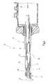
- FIG. 1shows a perspective view of a video endoscope according to a first illustrative embodiment, where parts of the video endoscope have been omitted, and where the video endoscope is depicted partially in longitudinal section;
- FIG. 1Ashows an enlarged view of a detail of the video endoscope in FIG. 1 ;
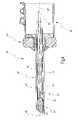
- FIG. 2shows a cutaway view of the video endoscope in FIG. 1 , on an enlarged scale and in longitudinal section;
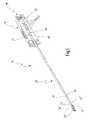
- FIG. 3shows a view of the video endoscope in FIG. 1 comparable to the view in FIG. 1 , but in another operating state compared to FIG. 1 ;
- FIG. 4shows the video endoscope in a view comparable to FIG. 2 and in the operating state shown in FIG. 3 ;
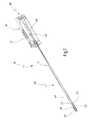
- FIG. 5shows a perspective view of a video endoscope according to another illustrative embodiment, where parts of the video endoscope have been omitted, and where the video endoscope is depicted partially in longitudinal section;
- FIG. 6shows a cutaway view of the video endoscope in FIG. 5 , on an enlarged scale and in longitudinal section;
- FIG. 7shows the video endoscope from FIG. 5 in a view comparable to FIG. 5 , but in another operating state compared to FIG. 5 ;
- FIG. 8shows the video endoscope from FIG. 5 in a view comparable to FIG. 6 , and in the operating state of the video endoscope according to FIG. 7 ;
- FIG. 9shows another illustrative embodiment of an electrical connection for the video endoscope in FIG. 1 or in FIG. 5 .
- FIGS. 1 to 4A first illustrative embodiment of a video endoscope designated by the general reference number 10 is shown in FIGS. 1 to 4 . A detail of the video endoscope 10 is depicted in FIG. 1A .
- the video endoscope 10is used, for example in the context of minimally invasive surgery, for viewing an area of the body inside the body.
- the video endoscope 10comprises, according to FIGS. 2 and 4 , an elongate shaft 12 , which has been omitted in FIGS. 1 and 3 for the sake of clarity.
- the shaft 12has a longitudinal axis 14 .
- the video endoscope 10has a handpiece 16 , to which the shaft 12 is connected.
- the shaft 12is made up of several tubes pushed one inside another, specifically an outer tube 18 , a middle tube 20 arranged therein, and an inner tube 22 .
- the inner tube 22is able to rotate about the longitudinal axis 14 relative to the other two tubes 18 , 20 .
- a lens 24Arranged at the distal end of the shaft 12 there is a lens 24 which, for example, has two optical elements 26 and 28 .
- the lens 24is an oblique view lens, i.e. a viewing direction 30 of the lens 24 forms an angle 32 of ⁇ 0° with the longitudinal axis 14 of the shaft 12 , and, in the illustrative embodiment shown, the angle 32 is 30°.
- the lensis connected in a rotationally fixed manner to the middle and outer tubes 18 , 20 of the shaft 12 .
- an electronic image pickup 34Arranged in the proximal direction from the lens 24 , but still at the distal end of the shaft 12 , there is an electronic image pickup 34 .
- the electronic image pickup 34is securely connected to the distal end of the inner tube 22 .
- optical elementsfor example one or more filters, can be arranged between the lens 24 and the image pickup 34 .
- the electronic image pickup 34is designed, for example, in the form of a CCD or CMOS chip.
- the lens 24projects the viewed area of the body onto the image pickup 34 .
- the image pickup 34converts the received optical signals into electrical signals.
- the electronic image pickup 34is connected, via an electrical connection 36 , to an electrical connector piece 38 , which is here arranged at the proximal end of the handpiece 16 .
- the electrical connector piece 38is designed as a plug.
- the electrical connection 36is formed by at least one (in the illustrative embodiment according to FIGS. 1 to 4 by precisely one) flexible, elongate and narrow circuit board 40 , which is itself able to twist about its longitudinal direction, which corresponds to the direction of the longitudinal axis 14 .
- the circuit board 40carries a plurality of conductor tracks, for example in this case four conductor tracks 40 a , 40 b on one of its surfaces, which are designed as thin copper lines, for example. On the opposite side, the circuit board 40 can carry further conductor tracks.
- a distal end 42 of the circuit board 40is adjoined in the distal direction by a distal circuit board part 44 , which is rigid, or at least stiffer than the flexible circuit board 40 .
- the distal circuit board part 44serves for contact with the electronic image pickup 34 .
- the width B of the circuit board 40 and of the distal circuit board part 44is not greater than the corresponding width of the image pickup 34 .
- the distal circuit board part 44is thicker than the circuit board 40 , which is made as thin as possible in order to achieve a high degree of flexibility.
- the circuit board 40is in this case constructed in one layer from a planar base material, in particular polyimide, and the conductor tracks 40 a to 40 b are vapour-deposited, for example, onto the base material.
- the thickness of the circuit board 40is preferably 0.02 to 0.3 mm.
- the distal circuit board part 44carries electrical components, for example an amplifier circuit for (pre)amplification of the electrical video signals generated by the image pickup 34 .
- the circuit board 40extends all the way through the shaft 12 and into the handpiece 16 , where a proximal end 46 of the circuit board 40 is adjoined by a proximal circuit board part 48 .
- the proximal circuit board part 48carries further electrical components 50 for controlling the image pickup 34 .
- the proximal circuit board part 48is again stiffer than the circuit board 40 and can in particular also be rigid, thus making it easier to apply the electrical components 50 .
- the proximal circuit board part 48carries the electrical connector piece 38 at its proximal end, said electrical connector piece 38 in this case being designed as a plug contact.
- the electrical connector piece 38is connected to the proximal circuit board part 48 via a flexible bridge 52 .
- the circuit board 40 , the distal circuit board part 44 and the proximal circuit board part 48 and bridge 52can all be produced in one piece from the same base material, in which case the different degrees of flexibility between the circuit board 40 , the distal circuit board part 44 and the proximal circuit board part 48 can be obtained by suitable strengthening of the base material in the area of the distal circuit board part 44 and of the proximal circuit board part 48 .
- circuit board 40 , distal circuit board part 44 and proximal circuit board part 48can also be designed as a hybrid arrangement, i.e. the distal and proximal circuit board parts 44 and 48 can be produced from one base material, in particular a stiff base material, while the circuit board 40 can be produced from a particularly flexible base material, in particular a polymer, especially polyimide, and the individual circuit board parts are then connected to one another in a suitable way, for example by adhesive bonding.
- the polymercan also be thermosetting.
- the circuit board 40is preferably in one layer, and the conductor tracks 40 a to 40 d are arranged in at most two planes of the circuit board, for example on the two mutually opposite wide sides of the circuit board 40 .
- the circuit board 40can also have a multi-layer design, preferably constructed from two circuit board layers that are firmly connected to each other. However, to permit the greatest possible flexibility of the circuit board 40 , it must be ensured that the thickness of the circuit hoard 40 is kept as small as possible.
- circuit board 40it is also possible for the circuit board 40 to be provided with different degrees of flexibility between its proximal end 46 and its distal end 42 , with the flexibility decreasing from the proximal end 46 towards the distal end 42 , i.e. the circuit board 40 is stiffer in the area of the distal end 42 than it is in the area of the proximal end 46 .
- the distal circuit board part 44is constructed from two circuit board part layers 44 a and 44 b.
- the electronic image pickup 34is also rotatable about the longitudinal axis 14 of the shaft 12 relative to the electrical connector piece 38 and to the lens 24 .
- an adjustment member 54is provided which acts on the inner tube 22 and turns the latter about the longitudinal axis 14 of the shaft, as a result of which the image pickup 34 , which is fixedly connected to the inner tube 22 , is likewise rotated about the longitudinal axis 14 .
- the image pickup 34is rotatable about the longitudinal axis 14 in both directions of rotation (clockwise and anticlockwise), preferably by 180°.
- a rotation of the image pickup 34 relative to the electrical connector piece 38then causes a twisting of the circuit board 40 , as is shown in FIGS. 3 and 4 .
- FIG. 3shows the state in which the image pickup 34 is rotated through 180° about the longitudinal axis 14 relative to the position in FIG. 1 .
- the proximal circuit board part 48has not twisted, or has not appreciably twisted, whereas the distal circuit board part 44 has twisted through 180° along with the image pickup 34 .
- the conductor tracks 40 a to 40 dare not subjected or are subjected only minimally to compression and extension, as a result of which there is no risk of the conductor tracks 40 a to 40 d breaking, even in long-term use of the video endoscope 10 .
- the video endoscope 10has a channel 56 in which optical fibres extend for the illuminating light, a connector piece 58 for a fibre optic cable (not shown) being provided at the proximal end, and the light emerging from a light exit port 60 at the distal end of the shaft 12 .
- FIGS. 5 to 8show another illustrative embodiment of a video endoscope 10 ′ in which parts that are identical or comparable to those in the video endoscope 10 are provided with the same reference numbers, with an added prime sign. Only the differences from the video endoscope 10 are described below.
- the electrical connection 36 ′ between the image pickup 34 ′ and the electrical connector piece 38 ′is formed by two circuit boards 40 ′ and 41 , which are arranged lying one over the other in the shaft 12 ′ along the longitudinal axis 14 ′.
- the distal ends 42 ′, 43 ′ of the circuit boards 40 ′ and 41are once again adjoined by the distal circuit board part 44 ′.
- the number of conductor tracks for the electrical connection between the image pickup 34 ′ and the connector piece 38 ′can be increased without widening the individual circuit boards 40 ′ and 41 ′, and without the thickness and therefore the stiffness of the circuit boards 40 ′ and 41 being increased.
- the circuit board 41is also flexible and able to twist about its longitudinal direction.
- the circuit board 41 and the circuit board 40 ′are at a distance from each other and therefore movable relative to each other, as a result of which the overall flexibility of the two circuit boards 40 ′ and 41 is not reduced, or is not appreciably reduced, by comparison with just one circuit board.
- the circuit boards 41 and 40 ′are connected to each other via a flexible bridge 62 , which bridge 62 also forms an electrical connection between the circuit boards 40 ′ and 41 .
- the proximal circuit board part 48 ′need only be electrically connected to the circuit board 40 ′.
- circuit boards 40 ′ and 41Before installation of the circuit boards 40 ′ and 41 , they are preferably folded out from each other (cf. also FIG. 9 ) such that they lie in one plane.
- the circuit board part layer 44 ′ ais connected to the circuit board 41
- the circuit board part layer 44 ′ b of the distal circuit board part 44 ′is connected to the circuit board 40 ′.
- To insert the circuit boards 40 ′ and 41they are then bent via the bridge 62 into an arrangement in which they lie one over the other, as is shown in FIG. 6 , where the circuit board parts 44 ′ a and 44 ′ b are moved relative to each other upon insertion such that they can be pushed more easily through the shaft (inner tube 22 ).
- FIG. 7shows the video endoscope 10 ′ in a state in which the image pickup 34 ′ has been rotated through 180° from its position in FIG. 6 .
- the arrangement of the circuit boards 40 ′ and 41 lying one over the other and at a distance from each otherensures that they can move relative to each other and can each twist.
- the electrical connection 36 ′is formed by means of two circuit boards 40 ′ and 41 , these can be produced in one piece together with the circuit board parts 44 ′ and 48 ′ and the bridge 62 from the same planar base material, or they can be formed in a hybrid configuration from different base materials used for the circuit board parts 44 ′ and 48 ′ and the circuit boards 40 ′, 41 .
- FIG. 9shows another variant of an electrical connection 36 ′′ which can be used in the video endoscope 10 or the video endoscope 10 ′ instead of the electrical connections 36 and 36 ′.
- the electrical connection 36 ′′here has two circuit boards 40 ′′ and 41 ′′, the circuit board 40 ′′ having a distal circuit board part 44 b ′′ at its distal end, and the circuit board 41 ′′ having a distal circuit board part 44 a ′′ at its distal end.
- the arrangement to this extentcorresponds to the embodiment in FIGS. 5 to 8 , with the circuit boards 40 ′′ and 41 ′′ still being arranged lying next to each other. At their proximal end, the circuit boards 40 ′′ and 41 ′′ are connected to each other via the flexible bridge 62 ′′.
- the circuit board 41 ′′ with its distal circuit board part 44 a ′′is folded through 180° about a mirror axis 64 and onto the circuit board 40 ′′, such that the resulting arrangement corresponds to the arrangement of the circuit boards 40 ′ and 41 according to FIGS. 5 to 8 .
- the electrical connection 36 ′′differs from the previous electrical connections 36 and 36 ′ in that the proximal circuit board part 48 ′′ is constructed in two parts, specifically a first circuit board part 48 a ′′ and a second circuit board part 48 b ′′.
- the circuit board parts 48 a ′′ and 48 b ′′are connected via a flexible bridge 49 , which connects the circuit board parts 48 a ′′ and 48 b ′′ not just mechanically, but also electrically.
- the electrical connector piece 38 ′′is provided on the circuit board part 48 a ′′ via the flexible bridge 52 ′′.
- circuit board parts 48 a ′′ and 48 b ′′are folded onto each other about an axis 66 , i.e. they then lie one over the other in the handpiece 16 or 16 ′.
- Both circuit board parts 48 a ′′ and 48 b ′′carry the electrical components 50 a ′′ and 50 b′′.
Landscapes
- Health & Medical Sciences (AREA)
- Life Sciences & Earth Sciences (AREA)
- Surgery (AREA)
- Biomedical Technology (AREA)
- Medical Informatics (AREA)
- Optics & Photonics (AREA)
- Pathology (AREA)
- Radiology & Medical Imaging (AREA)
- Biophysics (AREA)
- Engineering & Computer Science (AREA)
- Physics & Mathematics (AREA)
- Heart & Thoracic Surgery (AREA)
- Nuclear Medicine, Radiotherapy & Molecular Imaging (AREA)
- Molecular Biology (AREA)
- Animal Behavior & Ethology (AREA)
- General Health & Medical Sciences (AREA)
- Public Health (AREA)
- Veterinary Medicine (AREA)
- Endoscopes (AREA)
- Instruments For Viewing The Inside Of Hollow Bodies (AREA)
Abstract
Description
Claims (23)
Applications Claiming Priority (3)
| Application Number | Priority Date | Filing Date | Title |
|---|---|---|---|
| DE102007009292 | 2007-02-16 | ||
| DE102007009292ADE102007009292A1 (en) | 2007-02-16 | 2007-02-16 | Videoscope |
| DE102007009292.1 | 2007-02-16 |
Publications (2)
| Publication Number | Publication Date |
|---|---|
| US20080214892A1 US20080214892A1 (en) | 2008-09-04 |
| US8187171B2true US8187171B2 (en) | 2012-05-29 |
Family
ID=39472635
Family Applications (1)
| Application Number | Title | Priority Date | Filing Date |
|---|---|---|---|
| US12/031,345Expired - Fee RelatedUS8187171B2 (en) | 2007-02-16 | 2008-02-14 | Video endoscope |
Country Status (4)
| Country | Link |
|---|---|
| US (1) | US8187171B2 (en) |
| EP (1) | EP1958564B1 (en) |
| AT (1) | ATE511783T1 (en) |
| DE (1) | DE102007009292A1 (en) |
Cited By (50)
| Publication number | Priority date | Publication date | Assignee | Title |
|---|---|---|---|---|
| US8926502B2 (en) | 2011-03-07 | 2015-01-06 | Endochoice, Inc. | Multi camera endoscope having a side service channel |
| US9011799B2 (en) | 2011-08-11 | 2015-04-21 | Eppendorf Ag | Laboratory sample instrument with printed circuit board cable device |
| US9101287B2 (en) | 2011-03-07 | 2015-08-11 | Endochoice Innovation Center Ltd. | Multi camera endoscope assembly having multiple working channels |
| US9101268B2 (en) | 2009-06-18 | 2015-08-11 | Endochoice Innovation Center Ltd. | Multi-camera endoscope |
| US9101266B2 (en) | 2011-02-07 | 2015-08-11 | Endochoice Innovation Center Ltd. | Multi-element cover for a multi-camera endoscope |
| USD745670S1 (en)* | 2014-05-16 | 2015-12-15 | Karl Storz Gmbh & Co. Kg | Video endoscope |
| US9314147B2 (en) | 2011-12-13 | 2016-04-19 | Endochoice Innovation Center Ltd. | Rotatable connector for an endoscope |
| US9320419B2 (en) | 2010-12-09 | 2016-04-26 | Endochoice Innovation Center Ltd. | Fluid channeling component of a multi-camera endoscope |
| US9402533B2 (en) | 2011-03-07 | 2016-08-02 | Endochoice Innovation Center Ltd. | Endoscope circuit board assembly |
| US9492063B2 (en) | 2009-06-18 | 2016-11-15 | Endochoice Innovation Center Ltd. | Multi-viewing element endoscope |
| US9554692B2 (en) | 2009-06-18 | 2017-01-31 | EndoChoice Innovation Ctr. Ltd. | Multi-camera endoscope |
| US9560954B2 (en) | 2012-07-24 | 2017-02-07 | Endochoice, Inc. | Connector for use with endoscope |
| US9560953B2 (en) | 2010-09-20 | 2017-02-07 | Endochoice, Inc. | Operational interface in a multi-viewing element endoscope |
| US9642513B2 (en) | 2009-06-18 | 2017-05-09 | Endochoice Inc. | Compact multi-viewing element endoscope system |
| US9655502B2 (en) | 2011-12-13 | 2017-05-23 | EndoChoice Innovation Center, Ltd. | Removable tip endoscope |
| US20170188795A1 (en)* | 2016-01-05 | 2017-07-06 | UroSee Corporation | Handheld endoscope |
| US9706903B2 (en) | 2009-06-18 | 2017-07-18 | Endochoice, Inc. | Multiple viewing elements endoscope system with modular imaging units |
| US9713417B2 (en) | 2009-06-18 | 2017-07-25 | Endochoice, Inc. | Image capture assembly for use in a multi-viewing elements endoscope |
| US9814374B2 (en) | 2010-12-09 | 2017-11-14 | Endochoice Innovation Center Ltd. | Flexible electronic circuit board for a multi-camera endoscope |
| US9872609B2 (en) | 2009-06-18 | 2018-01-23 | Endochoice Innovation Center Ltd. | Multi-camera endoscope |
| US9901244B2 (en) | 2009-06-18 | 2018-02-27 | Endochoice, Inc. | Circuit board assembly of a multiple viewing elements endoscope |
| US9907457B2 (en) | 2013-02-01 | 2018-03-06 | Deka Products Limited Partnership | Endoscope with pannable camera |
| US9986899B2 (en) | 2013-03-28 | 2018-06-05 | Endochoice, Inc. | Manifold for a multiple viewing elements endoscope |
| US9993142B2 (en) | 2013-03-28 | 2018-06-12 | Endochoice, Inc. | Fluid distribution device for a multiple viewing elements endoscope |
| US10080486B2 (en) | 2010-09-20 | 2018-09-25 | Endochoice Innovation Center Ltd. | Multi-camera endoscope having fluid channels |
| US10165929B2 (en) | 2009-06-18 | 2019-01-01 | Endochoice, Inc. | Compact multi-viewing element endoscope system |
| US10203493B2 (en) | 2010-10-28 | 2019-02-12 | Endochoice Innovation Center Ltd. | Optical systems for multi-sensor endoscopes |
| US10278563B2 (en) | 2015-02-23 | 2019-05-07 | Uroviu Corp. | Handheld surgical endoscope with detachable cannula |
| US10499794B2 (en) | 2013-05-09 | 2019-12-10 | Endochoice, Inc. | Operational interface in a multi-viewing element endoscope |
| US10616491B2 (en) | 2013-02-01 | 2020-04-07 | Deka Products Limited Partnership | Endoscope with pannable camera and related method |
| US10869592B2 (en) | 2015-02-23 | 2020-12-22 | Uroviu Corp. | Handheld surgical endoscope |
| EP3753471A1 (en) | 2019-06-22 | 2020-12-23 | Karl Storz SE & Co. KG | Video endoscope and handle for a video endoscope |
| US11253141B2 (en) | 2015-02-23 | 2022-02-22 | Uroviu Corporation | Handheld surgical endoscope |
| US11278190B2 (en) | 2009-06-18 | 2022-03-22 | Endochoice, Inc. | Multi-viewing element endoscope |
| WO2022137233A1 (en)* | 2020-12-23 | 2022-06-30 | 270 Surgical Ltd. | Multi-camera endoscopes with maneuverable tips |
| US11547275B2 (en) | 2009-06-18 | 2023-01-10 | Endochoice, Inc. | Compact multi-viewing element endoscope system |
| US11596298B2 (en)* | 2018-08-27 | 2023-03-07 | Meditrina, Inc. | Endoscope and method of use |
| US11684248B2 (en) | 2017-09-25 | 2023-06-27 | Micronvision Corp. | Endoscopy/stereo colposcopy medical instrument |
| US11771304B1 (en) | 2020-11-12 | 2023-10-03 | Micronvision Corp. | Minimally invasive endoscope |
| US11832797B2 (en) | 2016-09-25 | 2023-12-05 | Micronvision Corp. | Endoscopic fluorescence imaging |
| US11864734B2 (en) | 2009-06-18 | 2024-01-09 | Endochoice, Inc. | Multi-camera endoscope |
| US11889986B2 (en) | 2010-12-09 | 2024-02-06 | Endochoice, Inc. | Flexible electronic circuit board for a multi-camera endoscope |
| US11944267B2 (en) | 2019-07-25 | 2024-04-02 | Uroviu Corp. | Disposable endoscopy cannula with integrated grasper |
| US11980342B2 (en) | 2020-11-12 | 2024-05-14 | Micronvision Corp. | Minimally invasive endoscope |
| US11986162B2 (en) | 2018-04-26 | 2024-05-21 | Deka Products Limited Partnership | Endoscope with rotatable camera and related methods |
| US12137873B2 (en) | 2009-06-18 | 2024-11-12 | Endochoice, Inc. | Compact multi-viewing element endoscope system |
| US12204087B2 (en) | 2010-10-28 | 2025-01-21 | Endochoice, Inc. | Optical systems for multi-sensor endoscopes |
| US12220105B2 (en) | 2010-06-16 | 2025-02-11 | Endochoice, Inc. | Circuit board assembly of a multiple viewing elements endoscope |
| US12268358B2 (en) | 2019-12-05 | 2025-04-08 | Uroviu Corp. | Portable endoscope with side-mountable disposable portion |
| DE102024102627A1 (en)* | 2024-01-30 | 2025-07-31 | Ambu A/S | Endoscope with guide wire arrangement |
Families Citing this family (22)
| Publication number | Priority date | Publication date | Assignee | Title |
|---|---|---|---|---|
| DE102007026234A1 (en)* | 2007-05-31 | 2008-12-04 | Karl Storz Gmbh & Co. Kg | Videoscope |
| KR100960262B1 (en)* | 2008-08-14 | 2010-06-07 | 한전케이피에스 주식회사 | Shape-Flexible Thin-Film Type Endoscope Using Imaging Device |
| DE102010063482A1 (en)* | 2010-12-20 | 2012-06-21 | Karl Storz Gmbh & Co. Kg | Electrical cable for electrical energy and data transmission |
| DE102011089157A1 (en)* | 2011-12-20 | 2013-06-20 | Olympus Winter & Ibe Gmbh | Video endoscope with lateral viewing direction and method for mounting a video endoscope |
| DE102012005037A1 (en) | 2012-03-15 | 2013-09-19 | Olympus Winter & Ibe Gmbh | Endoscope, particularly video endoscope for use in laparoscopic surgery, comprises circuit divided into mechanically and electrically coupled modules that have circuit carriers, which are coupled to one another by mechanical coupling unit |
| DE102012017589A1 (en) | 2012-09-06 | 2014-03-06 | Olympus Winter & Ibe Gmbh | Conductor track carrier for use in medical video endoscope used in humid environment, has strip conductor whose distal ends are connected to electronic image sensor, and proximal ends are connected to current feed-through device |
| DE102012022475A1 (en)* | 2012-11-19 | 2014-05-22 | Olympus Winter & Ibe Gmbh | Video endoscope and method for its production |
| BR112015022941A2 (en)* | 2013-03-15 | 2017-07-18 | Olive Medical Corp | mechanical image rotation for tightly coupled image sensor and endoscope |
| DE102014212712A1 (en)* | 2014-07-01 | 2016-01-07 | Olympus Winter & Ibe Gmbh | Video endoscope with flexible printed circuit board |
| JP5945653B1 (en)* | 2014-10-20 | 2016-07-05 | オリンパス株式会社 | Solid-state imaging device and electronic endoscope provided with the solid-state imaging device |
| CN113208544B (en)* | 2015-09-01 | 2025-02-25 | 德卡产品有限公司 | Endoscope with panning camera and related methods |
| DE102015118199A1 (en) | 2015-10-26 | 2017-04-27 | Karl Storz Gmbh & Co. Kg | Optical medical instrument |
| JP6637933B2 (en)* | 2017-08-31 | 2020-01-29 | 株式会社フジクラ | Imaging module |
| JP6641330B2 (en) | 2017-08-31 | 2020-02-05 | 株式会社フジクラ | Catheter with imaging module |
| JP6641329B2 (en)* | 2017-08-31 | 2020-02-05 | 株式会社フジクラ | Catheter with imaging module |
| DE102017131171A1 (en) | 2017-12-22 | 2019-06-27 | Olympus Winter & Ibe Gmbh | Videoscope |
| US10433717B1 (en) | 2018-06-28 | 2019-10-08 | Meditrina, Inc. | Endoscope having size-adjustable working channel |
| DE102019100395B4 (en)* | 2019-01-09 | 2025-06-26 | Olympus Winter & Ibe Gmbh | Connecting body of an endoscope and method for assembling an endoscope |
| DE102019105564B4 (en)* | 2019-03-05 | 2023-02-02 | Olympus Winter & Ibe Gmbh | endoscope |
| WO2021071715A1 (en)* | 2019-10-07 | 2021-04-15 | Boston Scientific Scimed, Inc. | Endoscopic device with interchangeable shaft |
| EP4321858A1 (en)* | 2022-08-08 | 2024-02-14 | viZaar Industrial imaging AG | Probe for optical inspection, maintenance and repair of machines, electric generators, turbines and steam generators |
| DE102023112524A1 (en) | 2023-05-10 | 2024-11-14 | Olympus Winter & Ibe Gmbh | Arrangement for protecting electrical connections of an electrical transmission line within a shaft of an endoscope and an endoscope |
Citations (20)
| Publication number | Priority date | Publication date | Assignee | Title |
|---|---|---|---|---|
| US4858001A (en) | 1987-10-08 | 1989-08-15 | High-Tech Medical Instrumentation, Inc. | Modular endoscopic apparatus with image rotation |
| US5313306A (en) | 1991-05-13 | 1994-05-17 | Telerobotics International, Inc. | Omniview motionless camera endoscopy system |
| WO1995001749A1 (en) | 1993-07-09 | 1995-01-19 | Saturnus A.G. | Tv camera with rotational orientation correction |
| US5621830A (en)* | 1995-06-07 | 1997-04-15 | Smith & Nephew Dyonics Inc. | Rotatable fiber optic joint |
| EP0904725A1 (en) | 1997-02-13 | 1999-03-31 | Matsushita Electric Industrial Co., Ltd. | Endoscope, method of manufacturing the same, and inserting member |
| US6097423A (en)* | 1997-06-06 | 2000-08-01 | Karl Storz Imaging, Inc. | Image orientation for endoscopic video displays |
| FR2800983A1 (en) | 1999-11-17 | 2001-05-18 | Winter & Ibe Olympus | Endoscope has video camera located at entry end and within free space adjacent to optical fibres and service channel and electric motor which is able to maintain normal picture configuration |
| DE20113031U1 (en) | 2001-08-04 | 2001-12-20 | Olympus Winter & Ibe Gmbh, 22045 Hamburg | Video endoscope with rotating video camera |
| US20020062083A1 (en) | 2000-11-21 | 2002-05-23 | Asahi Kogaku Kogyo Kabushiki Kaisha | Ultrasonic endoscope |
| US6471637B1 (en)* | 1999-09-24 | 2002-10-29 | Karl Storz Imaging, Inc. | Image orientation for endoscopic video displays |
| US20020161280A1 (en)* | 1999-09-24 | 2002-10-31 | David Chatenever | Image orientation for endoscopic video displays |
| WO2002102224A2 (en) | 2001-06-18 | 2002-12-27 | Given Imaging Ltd. | In vivo sensing device with a circuit board having rigid sections and flexible sections |
| US20040171912A1 (en) | 2003-02-27 | 2004-09-02 | Olympus Corporation | Operating mechanism for medical device |
| US20050174479A1 (en)* | 2004-02-10 | 2005-08-11 | Pentax Corporation | Digital camera |
| US20050197533A1 (en)* | 2000-03-16 | 2005-09-08 | Medivision, Inc. | Endoscope and camera mount |
| DE102004023866B3 (en) | 2004-05-12 | 2006-02-23 | Olympus Winter & Ibe Gmbh | Video endoscope has tube containing rotatable video camera with multiple connection leads on flexible circuit |
| US20060058581A1 (en) | 2004-09-11 | 2006-03-16 | Olympus Winter & Ibe Gmbh | Video endoscope with a rotatable video camera |
| US20060129032A1 (en)* | 2000-08-30 | 2006-06-15 | Durell & Gitelis, Inc. | Variable view arthroscope with charge coupled device |
| US7108657B2 (en)* | 2001-03-30 | 2006-09-19 | Karl Storz Gmbh & Co. Kg | Endoscopic visualization apparatus with different imaging systems |
| US20080108869A1 (en)* | 2006-10-20 | 2008-05-08 | Femsuite Llc | Optical surgical device and methods of use |
- 2007
- 2007-02-16DEDE102007009292Apatent/DE102007009292A1/ennot_activeWithdrawn
- 2008
- 2008-02-02EPEP08001973Apatent/EP1958564B1/enactiveActive
- 2008-02-02ATAT08001973Tpatent/ATE511783T1/enactive
- 2008-02-14USUS12/031,345patent/US8187171B2/ennot_activeExpired - Fee Related
Patent Citations (27)
| Publication number | Priority date | Publication date | Assignee | Title |
|---|---|---|---|---|
| US4858001A (en) | 1987-10-08 | 1989-08-15 | High-Tech Medical Instrumentation, Inc. | Modular endoscopic apparatus with image rotation |
| US4858001B1 (en) | 1987-10-08 | 1992-06-30 | High Tech Medical Instrumentat | |
| US5313306A (en) | 1991-05-13 | 1994-05-17 | Telerobotics International, Inc. | Omniview motionless camera endoscopy system |
| WO1995001749A1 (en) | 1993-07-09 | 1995-01-19 | Saturnus A.G. | Tv camera with rotational orientation correction |
| EP0712289A1 (en) | 1993-07-09 | 1996-05-22 | Saturnus Ag | Tv camera with rotational orientation correction |
| US5621830A (en)* | 1995-06-07 | 1997-04-15 | Smith & Nephew Dyonics Inc. | Rotatable fiber optic joint |
| EP0904725A1 (en) | 1997-02-13 | 1999-03-31 | Matsushita Electric Industrial Co., Ltd. | Endoscope, method of manufacturing the same, and inserting member |
| US6293910B1 (en)* | 1997-02-13 | 2001-09-25 | Matsushita Electric Industrial Co., Ltd. | Endoscope, method of manufacturing the same, and insertion member |
| US6097423A (en)* | 1997-06-06 | 2000-08-01 | Karl Storz Imaging, Inc. | Image orientation for endoscopic video displays |
| US20020161280A1 (en)* | 1999-09-24 | 2002-10-31 | David Chatenever | Image orientation for endoscopic video displays |
| US6471637B1 (en)* | 1999-09-24 | 2002-10-29 | Karl Storz Imaging, Inc. | Image orientation for endoscopic video displays |
| US6464631B1 (en) | 1999-11-17 | 2002-10-15 | Olympus Winter & Ibe Gmbh | Endoscope with a distal video camera and a camera rotating device |
| FR2800983A1 (en) | 1999-11-17 | 2001-05-18 | Winter & Ibe Olympus | Endoscope has video camera located at entry end and within free space adjacent to optical fibres and service channel and electric motor which is able to maintain normal picture configuration |
| US20050197533A1 (en)* | 2000-03-16 | 2005-09-08 | Medivision, Inc. | Endoscope and camera mount |
| US20060129032A1 (en)* | 2000-08-30 | 2006-06-15 | Durell & Gitelis, Inc. | Variable view arthroscope with charge coupled device |
| US6488631B2 (en) | 2000-11-21 | 2002-12-03 | Asahi Kogaku Kogyo Kabushiki Kaisha | Ultrasonic endoscope |
| US20020062083A1 (en) | 2000-11-21 | 2002-05-23 | Asahi Kogaku Kogyo Kabushiki Kaisha | Ultrasonic endoscope |
| US7108657B2 (en)* | 2001-03-30 | 2006-09-19 | Karl Storz Gmbh & Co. Kg | Endoscopic visualization apparatus with different imaging systems |
| WO2002102224A2 (en) | 2001-06-18 | 2002-12-27 | Given Imaging Ltd. | In vivo sensing device with a circuit board having rigid sections and flexible sections |
| DE20113031U1 (en) | 2001-08-04 | 2001-12-20 | Olympus Winter & Ibe Gmbh, 22045 Hamburg | Video endoscope with rotating video camera |
| US20040171912A1 (en) | 2003-02-27 | 2004-09-02 | Olympus Corporation | Operating mechanism for medical device |
| US20050174479A1 (en)* | 2004-02-10 | 2005-08-11 | Pentax Corporation | Digital camera |
| DE102004023866B3 (en) | 2004-05-12 | 2006-02-23 | Olympus Winter & Ibe Gmbh | Video endoscope has tube containing rotatable video camera with multiple connection leads on flexible circuit |
| DE102004044119A1 (en) | 2004-09-11 | 2006-03-30 | Olympus Winter & Ibe Gmbh | Video endoscope with rotatable video camera |
| US20060058581A1 (en) | 2004-09-11 | 2006-03-16 | Olympus Winter & Ibe Gmbh | Video endoscope with a rotatable video camera |
| US7713189B2 (en)* | 2004-09-11 | 2010-05-11 | Olympus Winter & Ibe Gmbh | Video endoscope with a rotatable video camera |
| US20080108869A1 (en)* | 2006-10-20 | 2008-05-08 | Femsuite Llc | Optical surgical device and methods of use |
Non-Patent Citations (1)
| Title |
|---|
| European Search Report, EP08001973, Aug. 14, 2008, 6 Pages. |
Cited By (92)
| Publication number | Priority date | Publication date | Assignee | Title |
|---|---|---|---|---|
| US12137873B2 (en) | 2009-06-18 | 2024-11-12 | Endochoice, Inc. | Compact multi-viewing element endoscope system |
| US11471028B2 (en) | 2009-06-18 | 2022-10-18 | Endochoice, Inc. | Circuit board assembly of a multiple viewing elements endoscope |
| US10912445B2 (en) | 2009-06-18 | 2021-02-09 | Endochoice, Inc. | Compact multi-viewing element endoscope system |
| US9101268B2 (en) | 2009-06-18 | 2015-08-11 | Endochoice Innovation Center Ltd. | Multi-camera endoscope |
| US10905320B2 (en) | 2009-06-18 | 2021-02-02 | Endochoice, Inc. | Multi-camera endoscope |
| US12336686B2 (en) | 2009-06-18 | 2025-06-24 | Endochoice, Inc. | Multi-viewing element endoscope |
| US11534056B2 (en) | 2009-06-18 | 2022-12-27 | Endochoice, Inc. | Multi-camera endoscope |
| US10799095B2 (en) | 2009-06-18 | 2020-10-13 | Endochoice, Inc. | Multi-viewing element endoscope |
| US10791909B2 (en) | 2009-06-18 | 2020-10-06 | Endochoice, Inc. | Image capture assembly for use in a multi-viewing elements endoscope |
| US10765305B2 (en) | 2009-06-18 | 2020-09-08 | Endochoice, Inc. | Circuit board assembly of a multiple viewing elements endoscope |
| US9492063B2 (en) | 2009-06-18 | 2016-11-15 | Endochoice Innovation Center Ltd. | Multi-viewing element endoscope |
| US9554692B2 (en) | 2009-06-18 | 2017-01-31 | EndoChoice Innovation Ctr. Ltd. | Multi-camera endoscope |
| US10638922B2 (en) | 2009-06-18 | 2020-05-05 | Endochoice, Inc. | Multi-camera endoscope |
| US11278190B2 (en) | 2009-06-18 | 2022-03-22 | Endochoice, Inc. | Multi-viewing element endoscope |
| US9642513B2 (en) | 2009-06-18 | 2017-05-09 | Endochoice Inc. | Compact multi-viewing element endoscope system |
| US11547275B2 (en) | 2009-06-18 | 2023-01-10 | Endochoice, Inc. | Compact multi-viewing element endoscope system |
| US12303106B2 (en) | 2009-06-18 | 2025-05-20 | Endochoice, Inc. | Multi-camera endoscope |
| US9706905B2 (en) | 2009-06-18 | 2017-07-18 | Endochoice Innovation Center Ltd. | Multi-camera endoscope |
| US9706903B2 (en) | 2009-06-18 | 2017-07-18 | Endochoice, Inc. | Multiple viewing elements endoscope system with modular imaging units |
| US9713417B2 (en) | 2009-06-18 | 2017-07-25 | Endochoice, Inc. | Image capture assembly for use in a multi-viewing elements endoscope |
| US11864734B2 (en) | 2009-06-18 | 2024-01-09 | Endochoice, Inc. | Multi-camera endoscope |
| US11986155B2 (en) | 2009-06-18 | 2024-05-21 | Endochoice, Inc. | Multi-viewing element endoscope |
| US10165929B2 (en) | 2009-06-18 | 2019-01-01 | Endochoice, Inc. | Compact multi-viewing element endoscope system |
| US9872609B2 (en) | 2009-06-18 | 2018-01-23 | Endochoice Innovation Center Ltd. | Multi-camera endoscope |
| US10092167B2 (en) | 2009-06-18 | 2018-10-09 | Endochoice, Inc. | Multiple viewing elements endoscope system with modular imaging units |
| US9901244B2 (en) | 2009-06-18 | 2018-02-27 | Endochoice, Inc. | Circuit board assembly of a multiple viewing elements endoscope |
| US12220105B2 (en) | 2010-06-16 | 2025-02-11 | Endochoice, Inc. | Circuit board assembly of a multiple viewing elements endoscope |
| US9560953B2 (en) | 2010-09-20 | 2017-02-07 | Endochoice, Inc. | Operational interface in a multi-viewing element endoscope |
| US9986892B2 (en) | 2010-09-20 | 2018-06-05 | Endochoice, Inc. | Operational interface in a multi-viewing element endoscope |
| US10080486B2 (en) | 2010-09-20 | 2018-09-25 | Endochoice Innovation Center Ltd. | Multi-camera endoscope having fluid channels |
| US10203493B2 (en) | 2010-10-28 | 2019-02-12 | Endochoice Innovation Center Ltd. | Optical systems for multi-sensor endoscopes |
| US12204087B2 (en) | 2010-10-28 | 2025-01-21 | Endochoice, Inc. | Optical systems for multi-sensor endoscopes |
| US11543646B2 (en) | 2010-10-28 | 2023-01-03 | Endochoice, Inc. | Optical systems for multi-sensor endoscopes |
| US10898063B2 (en) | 2010-12-09 | 2021-01-26 | Endochoice, Inc. | Flexible electronic circuit board for a multi camera endoscope |
| US9320419B2 (en) | 2010-12-09 | 2016-04-26 | Endochoice Innovation Center Ltd. | Fluid channeling component of a multi-camera endoscope |
| US11497388B2 (en) | 2010-12-09 | 2022-11-15 | Endochoice, Inc. | Flexible electronic circuit board for a multi-camera endoscope |
| US9814374B2 (en) | 2010-12-09 | 2017-11-14 | Endochoice Innovation Center Ltd. | Flexible electronic circuit board for a multi-camera endoscope |
| US10182707B2 (en) | 2010-12-09 | 2019-01-22 | Endochoice Innovation Center Ltd. | Fluid channeling component of a multi-camera endoscope |
| US11889986B2 (en) | 2010-12-09 | 2024-02-06 | Endochoice, Inc. | Flexible electronic circuit board for a multi-camera endoscope |
| US10070774B2 (en) | 2011-02-07 | 2018-09-11 | Endochoice Innovation Center Ltd. | Multi-element cover for a multi-camera endoscope |
| US9351629B2 (en) | 2011-02-07 | 2016-05-31 | Endochoice Innovation Center Ltd. | Multi-element cover for a multi-camera endoscope |
| US9101266B2 (en) | 2011-02-07 | 2015-08-11 | Endochoice Innovation Center Ltd. | Multi-element cover for a multi-camera endoscope |
| US9101287B2 (en) | 2011-03-07 | 2015-08-11 | Endochoice Innovation Center Ltd. | Multi camera endoscope assembly having multiple working channels |
| US10292578B2 (en) | 2011-03-07 | 2019-05-21 | Endochoice Innovation Center Ltd. | Multi camera endoscope assembly having multiple working channels |
| US11026566B2 (en) | 2011-03-07 | 2021-06-08 | Endochoice, Inc. | Multi camera endoscope assembly having multiple working channels |
| US9713415B2 (en) | 2011-03-07 | 2017-07-25 | Endochoice Innovation Center Ltd. | Multi camera endoscope having a side service channel |
| US8926502B2 (en) | 2011-03-07 | 2015-01-06 | Endochoice, Inc. | Multi camera endoscope having a side service channel |
| US9854959B2 (en) | 2011-03-07 | 2018-01-02 | Endochoice Innovation Center Ltd. | Multi camera endoscope assembly having multiple working channels |
| US9402533B2 (en) | 2011-03-07 | 2016-08-02 | Endochoice Innovation Center Ltd. | Endoscope circuit board assembly |
| US9011799B2 (en) | 2011-08-11 | 2015-04-21 | Eppendorf Ag | Laboratory sample instrument with printed circuit board cable device |
| US9314147B2 (en) | 2011-12-13 | 2016-04-19 | Endochoice Innovation Center Ltd. | Rotatable connector for an endoscope |
| US9655502B2 (en) | 2011-12-13 | 2017-05-23 | EndoChoice Innovation Center, Ltd. | Removable tip endoscope |
| US12290241B2 (en) | 2011-12-13 | 2025-05-06 | Endochoice, Inc. | Removable tip endoscope |
| US10470649B2 (en) | 2011-12-13 | 2019-11-12 | Endochoice, Inc. | Removable tip endoscope |
| US11291357B2 (en) | 2011-12-13 | 2022-04-05 | Endochoice, Inc. | Removable tip endoscope |
| US9560954B2 (en) | 2012-07-24 | 2017-02-07 | Endochoice, Inc. | Connector for use with endoscope |
| US10863888B2 (en) | 2013-02-01 | 2020-12-15 | Deka Products Limited Partnership | Endoscope with pannable camera |
| US9907457B2 (en) | 2013-02-01 | 2018-03-06 | Deka Products Limited Partnership | Endoscope with pannable camera |
| US12200363B2 (en) | 2013-02-01 | 2025-01-14 | Deka Products Limited Partnership | Endoscope with pannable camera and related method |
| US10616491B2 (en) | 2013-02-01 | 2020-04-07 | Deka Products Limited Partnership | Endoscope with pannable camera and related method |
| US12075975B2 (en) | 2013-02-01 | 2024-09-03 | Deka Products Limited Partnership | Endoscope with pannable camera |
| US10362927B2 (en) | 2013-02-01 | 2019-07-30 | Deka Products Limited Partnership | Endoscope with pannable camera |
| US11793393B2 (en) | 2013-03-28 | 2023-10-24 | Endochoice, Inc. | Manifold for a multiple viewing elements endoscope |
| US12232699B2 (en) | 2013-03-28 | 2025-02-25 | Endochoice, Inc. | Manifold for a multiple viewing elements endoscope |
| US10925471B2 (en) | 2013-03-28 | 2021-02-23 | Endochoice, Inc. | Fluid distribution device for a multiple viewing elements endoscope |
| US10905315B2 (en) | 2013-03-28 | 2021-02-02 | Endochoice, Inc. | Manifold for a multiple viewing elements endoscope |
| US9986899B2 (en) | 2013-03-28 | 2018-06-05 | Endochoice, Inc. | Manifold for a multiple viewing elements endoscope |
| US9993142B2 (en) | 2013-03-28 | 2018-06-12 | Endochoice, Inc. | Fluid distribution device for a multiple viewing elements endoscope |
| US11925323B2 (en) | 2013-03-28 | 2024-03-12 | Endochoice, Inc. | Fluid distribution device for a multiple viewing elements endoscope |
| US10499794B2 (en) | 2013-05-09 | 2019-12-10 | Endochoice, Inc. | Operational interface in a multi-viewing element endoscope |
| USD745670S1 (en)* | 2014-05-16 | 2015-12-15 | Karl Storz Gmbh & Co. Kg | Video endoscope |
| US10869592B2 (en) | 2015-02-23 | 2020-12-22 | Uroviu Corp. | Handheld surgical endoscope |
| US11844498B2 (en) | 2015-02-23 | 2023-12-19 | Uroviu Corporation | Handheld surgical endoscope |
| US11253141B2 (en) | 2015-02-23 | 2022-02-22 | Uroviu Corporation | Handheld surgical endoscope |
| US10278563B2 (en) | 2015-02-23 | 2019-05-07 | Uroviu Corp. | Handheld surgical endoscope with detachable cannula |
| US20170188795A1 (en)* | 2016-01-05 | 2017-07-06 | UroSee Corporation | Handheld endoscope |
| US9895048B2 (en)* | 2016-01-05 | 2018-02-20 | Urosee Corp. | Handheld endoscope |
| US11832797B2 (en) | 2016-09-25 | 2023-12-05 | Micronvision Corp. | Endoscopic fluorescence imaging |
| US11684248B2 (en) | 2017-09-25 | 2023-06-27 | Micronvision Corp. | Endoscopy/stereo colposcopy medical instrument |
| US11986162B2 (en) | 2018-04-26 | 2024-05-21 | Deka Products Limited Partnership | Endoscope with rotatable camera and related methods |
| US11596298B2 (en)* | 2018-08-27 | 2023-03-07 | Meditrina, Inc. | Endoscope and method of use |
| US12124022B2 (en) | 2018-08-27 | 2024-10-22 | Meditrina, Inc. | Endoscope and method of use |
| US11672405B2 (en) | 2019-06-22 | 2023-06-13 | Karl Storz Se & Co Kg | Video endoscope and handle, including driven rotation limitation, for video endoscope |
| US11547280B2 (en) | 2019-06-22 | 2023-01-10 | Karl Storz Se & Co Kg | Rotatable and detachable electrical coupling point |
| EP3753471A1 (en) | 2019-06-22 | 2020-12-23 | Karl Storz SE & Co. KG | Video endoscope and handle for a video endoscope |
| US11185216B2 (en) | 2019-06-22 | 2021-11-30 | Karl Storz Se & Co Kg | Video endoscope and handle for a video endoscope including rotational support means |
| US11944267B2 (en) | 2019-07-25 | 2024-04-02 | Uroviu Corp. | Disposable endoscopy cannula with integrated grasper |
| US12268358B2 (en) | 2019-12-05 | 2025-04-08 | Uroviu Corp. | Portable endoscope with side-mountable disposable portion |
| US11980342B2 (en) | 2020-11-12 | 2024-05-14 | Micronvision Corp. | Minimally invasive endoscope |
| US11771304B1 (en) | 2020-11-12 | 2023-10-03 | Micronvision Corp. | Minimally invasive endoscope |
| WO2022137233A1 (en)* | 2020-12-23 | 2022-06-30 | 270 Surgical Ltd. | Multi-camera endoscopes with maneuverable tips |
| DE102024102627A1 (en)* | 2024-01-30 | 2025-07-31 | Ambu A/S | Endoscope with guide wire arrangement |
Also Published As
| Publication number | Publication date |
|---|---|
| EP1958564A2 (en) | 2008-08-20 |
| ATE511783T1 (en) | 2011-06-15 |
| US20080214892A1 (en) | 2008-09-04 |
| DE102007009292A1 (en) | 2008-08-21 |
| EP1958564B1 (en) | 2011-06-08 |
| EP1958564A3 (en) | 2008-10-08 |
Similar Documents
| Publication | Publication Date | Title |
|---|---|---|
| US8187171B2 (en) | Video endoscope | |
| US9717398B2 (en) | Lighting system for endoscopic examinations | |
| KR101814830B1 (en) | Small diameter video camera heads and visualization probes and medical devices containing them | |
| US8289381B2 (en) | Endoscope with an imaging catheter assembly and method of configuring an endoscope | |
| JP5469867B2 (en) | Endoscope with imaging catheter assembly and method for constructing an endoscope | |
| US7553277B2 (en) | Endoscope with variable direction of view | |
| US10188275B2 (en) | Small diameter video camera heads and visualization probes and medical devices containing them | |
| US7753842B2 (en) | In vivo imaging device with a small cross sectional area | |
| US8821382B2 (en) | Image pickup unit | |
| JP6573960B2 (en) | Card edge connector for imaging sensors | |
| US20090231419A1 (en) | Endoscope Assembly and Method of Performing a Medical Procedure | |
| WO2009049322A2 (en) | Endoscope assembly comprising retrograde viewing imaging device and instrument channel | |
| US20190175001A1 (en) | Endoscope | |
| CN116548892B (en) | Circuit structure, front end assembly and endoscope | |
| US20250176810A1 (en) | Endoscopic instrument | |
| US20240285150A1 (en) | Systems and methods for endoscope proximal end design | |
| JP3902267B2 (en) | Endoscope | |
| CN119923217A (en) | Medical device components and parts | |
| JP2024146208A (en) | Endoscopy | |
| JP2003230537A (en) | Electronic endoscope processor |
Legal Events
| Date | Code | Title | Description |
|---|---|---|---|
| AS | Assignment | Owner name:KARL STORZ GMBH & CO. KG, GERMANY Free format text:ASSIGNMENT OF ASSIGNORS INTEREST;ASSIGNORS:IRION, KLAUS M.;SCHWARZ, PETER;GRAF, CHRISTIAN;AND OTHERS;REEL/FRAME:020851/0548;SIGNING DATES FROM 20080327 TO 20080331 Owner name:KARL STORZ GMBH & CO. KG, GERMANY Free format text:ASSIGNMENT OF ASSIGNORS INTEREST;ASSIGNORS:IRION, KLAUS M.;SCHWARZ, PETER;GRAF, CHRISTIAN;AND OTHERS;SIGNING DATES FROM 20080327 TO 20080331;REEL/FRAME:020851/0548 | |
| FEPP | Fee payment procedure | Free format text:PAYOR NUMBER ASSIGNED (ORIGINAL EVENT CODE: ASPN); ENTITY STATUS OF PATENT OWNER: LARGE ENTITY | |
| ZAAA | Notice of allowance and fees due | Free format text:ORIGINAL CODE: NOA | |
| ZAAB | Notice of allowance mailed | Free format text:ORIGINAL CODE: MN/=. | |
| STCF | Information on status: patent grant | Free format text:PATENTED CASE | |
| FPAY | Fee payment | Year of fee payment:4 | |
| AS | Assignment | Owner name:KARL STORZ SE & CO. KG, GERMANY Free format text:CHANGE OF NAME;ASSIGNOR:KARL STORZ GMBH & CO. KG;REEL/FRAME:045373/0627 Effective date:20170911 | |
| MAFP | Maintenance fee payment | Free format text:PAYMENT OF MAINTENANCE FEE, 8TH YEAR, LARGE ENTITY (ORIGINAL EVENT CODE: M1552); ENTITY STATUS OF PATENT OWNER: LARGE ENTITY Year of fee payment:8 | |
| FEPP | Fee payment procedure | Free format text:MAINTENANCE FEE REMINDER MAILED (ORIGINAL EVENT CODE: REM.); ENTITY STATUS OF PATENT OWNER: LARGE ENTITY | |
| STCH | Information on status: patent discontinuation | Free format text:PATENT EXPIRED DUE TO NONPAYMENT OF MAINTENANCE FEES UNDER 37 CFR 1.362 | |
| FP | Lapsed due to failure to pay maintenance fee | Effective date:20240529 |