US8186852B2 - Opto-thermal solution for multi-utility solid state lighting device using conic section geometries - Google Patents
Opto-thermal solution for multi-utility solid state lighting device using conic section geometriesDownload PDFInfo
- Publication number
- US8186852B2 US8186852B2US12/817,807US81780710AUS8186852B2US 8186852 B2US8186852 B2US 8186852B2US 81780710 AUS81780710 AUS 81780710AUS 8186852 B2US8186852 B2US 8186852B2
- Authority
- US
- United States
- Prior art keywords
- light
- circuit board
- housing
- cover
- assembly
- Prior art date
- Legal status (The legal status is an assumption and is not a legal conclusion. Google has not performed a legal analysis and makes no representation as to the accuracy of the status listed.)
- Expired - Fee Related, expires
Links
Images


Classifications
- F—MECHANICAL ENGINEERING; LIGHTING; HEATING; WEAPONS; BLASTING
- F21—LIGHTING
- F21V—FUNCTIONAL FEATURES OR DETAILS OF LIGHTING DEVICES OR SYSTEMS THEREOF; STRUCTURAL COMBINATIONS OF LIGHTING DEVICES WITH OTHER ARTICLES, NOT OTHERWISE PROVIDED FOR
- F21V9/00—Elements for modifying spectral properties, polarisation or intensity of the light emitted, e.g. filters
- F21V9/30—Elements containing photoluminescent material distinct from or spaced from the light source
- F—MECHANICAL ENGINEERING; LIGHTING; HEATING; WEAPONS; BLASTING
- F21—LIGHTING
- F21S—NON-PORTABLE LIGHTING DEVICES; SYSTEMS THEREOF; VEHICLE LIGHTING DEVICES SPECIALLY ADAPTED FOR VEHICLE EXTERIORS
- F21S2/00—Systems of lighting devices, not provided for in main groups F21S4/00 - F21S10/00 or F21S19/00, e.g. of modular construction
- F—MECHANICAL ENGINEERING; LIGHTING; HEATING; WEAPONS; BLASTING
- F21—LIGHTING
- F21V—FUNCTIONAL FEATURES OR DETAILS OF LIGHTING DEVICES OR SYSTEMS THEREOF; STRUCTURAL COMBINATIONS OF LIGHTING DEVICES WITH OTHER ARTICLES, NOT OTHERWISE PROVIDED FOR
- F21V3/00—Globes; Bowls; Cover glasses
- F—MECHANICAL ENGINEERING; LIGHTING; HEATING; WEAPONS; BLASTING
- F21—LIGHTING
- F21K—NON-ELECTRIC LIGHT SOURCES USING LUMINESCENCE; LIGHT SOURCES USING ELECTROCHEMILUMINESCENCE; LIGHT SOURCES USING CHARGES OF COMBUSTIBLE MATERIAL; LIGHT SOURCES USING SEMICONDUCTOR DEVICES AS LIGHT-GENERATING ELEMENTS; LIGHT SOURCES NOT OTHERWISE PROVIDED FOR
- F21K9/00—Light sources using semiconductor devices as light-generating elements, e.g. using light-emitting diodes [LED] or lasers
- F21K9/20—Light sources comprising attachment means
- F21K9/23—Retrofit light sources for lighting devices with a single fitting for each light source, e.g. for substitution of incandescent lamps with bayonet or threaded fittings
- F21K9/232—Retrofit light sources for lighting devices with a single fitting for each light source, e.g. for substitution of incandescent lamps with bayonet or threaded fittings specially adapted for generating an essentially omnidirectional light distribution, e.g. with a glass bulb
- F—MECHANICAL ENGINEERING; LIGHTING; HEATING; WEAPONS; BLASTING
- F21—LIGHTING
- F21K—NON-ELECTRIC LIGHT SOURCES USING LUMINESCENCE; LIGHT SOURCES USING ELECTROCHEMILUMINESCENCE; LIGHT SOURCES USING CHARGES OF COMBUSTIBLE MATERIAL; LIGHT SOURCES USING SEMICONDUCTOR DEVICES AS LIGHT-GENERATING ELEMENTS; LIGHT SOURCES NOT OTHERWISE PROVIDED FOR
- F21K9/00—Light sources using semiconductor devices as light-generating elements, e.g. using light-emitting diodes [LED] or lasers
- F21K9/60—Optical arrangements integrated in the light source, e.g. for improving the colour rendering index or the light extraction
- F21K9/64—Optical arrangements integrated in the light source, e.g. for improving the colour rendering index or the light extraction using wavelength conversion means distinct or spaced from the light-generating element, e.g. a remote phosphor layer
- F—MECHANICAL ENGINEERING; LIGHTING; HEATING; WEAPONS; BLASTING
- F21—LIGHTING
- F21V—FUNCTIONAL FEATURES OR DETAILS OF LIGHTING DEVICES OR SYSTEMS THEREOF; STRUCTURAL COMBINATIONS OF LIGHTING DEVICES WITH OTHER ARTICLES, NOT OTHERWISE PROVIDED FOR
- F21V13/00—Producing particular characteristics or distribution of the light emitted by means of a combination of elements specified in two or more of main groups F21V1/00 - F21V11/00
- F21V13/02—Combinations of only two kinds of elements
- F21V13/08—Combinations of only two kinds of elements the elements being filters or photoluminescent elements and reflectors
- F—MECHANICAL ENGINEERING; LIGHTING; HEATING; WEAPONS; BLASTING
- F21—LIGHTING
- F21V—FUNCTIONAL FEATURES OR DETAILS OF LIGHTING DEVICES OR SYSTEMS THEREOF; STRUCTURAL COMBINATIONS OF LIGHTING DEVICES WITH OTHER ARTICLES, NOT OTHERWISE PROVIDED FOR
- F21V19/00—Fastening of light sources or lamp holders
- F21V19/001—Fastening of light sources or lamp holders the light sources being semiconductors devices, e.g. LEDs
- F21V19/003—Fastening of light source holders, e.g. of circuit boards or substrates holding light sources
- F21V19/0035—Fastening of light source holders, e.g. of circuit boards or substrates holding light sources the fastening means being capable of simultaneously attaching of an other part, e.g. a housing portion or an optical component
- F—MECHANICAL ENGINEERING; LIGHTING; HEATING; WEAPONS; BLASTING
- F21—LIGHTING
- F21V—FUNCTIONAL FEATURES OR DETAILS OF LIGHTING DEVICES OR SYSTEMS THEREOF; STRUCTURAL COMBINATIONS OF LIGHTING DEVICES WITH OTHER ARTICLES, NOT OTHERWISE PROVIDED FOR
- F21V23/00—Arrangement of electric circuit elements in or on lighting devices
- F21V23/003—Arrangement of electric circuit elements in or on lighting devices the elements being electronics drivers or controllers for operating the light source, e.g. for a LED array
- F21V23/007—Arrangement of electric circuit elements in or on lighting devices the elements being electronics drivers or controllers for operating the light source, e.g. for a LED array enclosed in a casing
- F21V23/009—Arrangement of electric circuit elements in or on lighting devices the elements being electronics drivers or controllers for operating the light source, e.g. for a LED array enclosed in a casing the casing being inside the housing of the lighting device
- F—MECHANICAL ENGINEERING; LIGHTING; HEATING; WEAPONS; BLASTING
- F21—LIGHTING
- F21V—FUNCTIONAL FEATURES OR DETAILS OF LIGHTING DEVICES OR SYSTEMS THEREOF; STRUCTURAL COMBINATIONS OF LIGHTING DEVICES WITH OTHER ARTICLES, NOT OTHERWISE PROVIDED FOR
- F21V29/00—Protecting lighting devices from thermal damage; Cooling or heating arrangements specially adapted for lighting devices or systems
- F21V29/50—Cooling arrangements
- F21V29/70—Cooling arrangements characterised by passive heat-dissipating elements, e.g. heat-sinks
- F21V29/74—Cooling arrangements characterised by passive heat-dissipating elements, e.g. heat-sinks with fins or blades
- F21V29/75—Cooling arrangements characterised by passive heat-dissipating elements, e.g. heat-sinks with fins or blades with fins or blades having different shapes, thicknesses or spacing
- F—MECHANICAL ENGINEERING; LIGHTING; HEATING; WEAPONS; BLASTING
- F21—LIGHTING
- F21V—FUNCTIONAL FEATURES OR DETAILS OF LIGHTING DEVICES OR SYSTEMS THEREOF; STRUCTURAL COMBINATIONS OF LIGHTING DEVICES WITH OTHER ARTICLES, NOT OTHERWISE PROVIDED FOR
- F21V3/00—Globes; Bowls; Cover glasses
- F21V3/02—Globes; Bowls; Cover glasses characterised by the shape
- F—MECHANICAL ENGINEERING; LIGHTING; HEATING; WEAPONS; BLASTING
- F21—LIGHTING
- F21V—FUNCTIONAL FEATURES OR DETAILS OF LIGHTING DEVICES OR SYSTEMS THEREOF; STRUCTURAL COMBINATIONS OF LIGHTING DEVICES WITH OTHER ARTICLES, NOT OTHERWISE PROVIDED FOR
- F21V7/00—Reflectors for light sources
- F—MECHANICAL ENGINEERING; LIGHTING; HEATING; WEAPONS; BLASTING
- F21—LIGHTING
- F21V—FUNCTIONAL FEATURES OR DETAILS OF LIGHTING DEVICES OR SYSTEMS THEREOF; STRUCTURAL COMBINATIONS OF LIGHTING DEVICES WITH OTHER ARTICLES, NOT OTHERWISE PROVIDED FOR
- F21V7/00—Reflectors for light sources
- F21V7/04—Optical design
- F21V7/06—Optical design with parabolic curvature
- F—MECHANICAL ENGINEERING; LIGHTING; HEATING; WEAPONS; BLASTING
- F21—LIGHTING
- F21V—FUNCTIONAL FEATURES OR DETAILS OF LIGHTING DEVICES OR SYSTEMS THEREOF; STRUCTURAL COMBINATIONS OF LIGHTING DEVICES WITH OTHER ARTICLES, NOT OTHERWISE PROVIDED FOR
- F21V7/00—Reflectors for light sources
- F21V7/04—Optical design
- F21V7/08—Optical design with elliptical curvature
- F—MECHANICAL ENGINEERING; LIGHTING; HEATING; WEAPONS; BLASTING
- F21—LIGHTING
- F21V—FUNCTIONAL FEATURES OR DETAILS OF LIGHTING DEVICES OR SYSTEMS THEREOF; STRUCTURAL COMBINATIONS OF LIGHTING DEVICES WITH OTHER ARTICLES, NOT OTHERWISE PROVIDED FOR
- F21V7/00—Reflectors for light sources
- F21V7/22—Reflectors for light sources characterised by materials, surface treatments or coatings, e.g. dichroic reflectors
- F21V7/28—Reflectors for light sources characterised by materials, surface treatments or coatings, e.g. dichroic reflectors characterised by coatings
- F—MECHANICAL ENGINEERING; LIGHTING; HEATING; WEAPONS; BLASTING
- F21—LIGHTING
- F21V—FUNCTIONAL FEATURES OR DETAILS OF LIGHTING DEVICES OR SYSTEMS THEREOF; STRUCTURAL COMBINATIONS OF LIGHTING DEVICES WITH OTHER ARTICLES, NOT OTHERWISE PROVIDED FOR
- F21V9/00—Elements for modifying spectral properties, polarisation or intensity of the light emitted, e.g. filters
- F21V9/06—Elements for modifying spectral properties, polarisation or intensity of the light emitted, e.g. filters for filtering out ultraviolet radiation
- F—MECHANICAL ENGINEERING; LIGHTING; HEATING; WEAPONS; BLASTING
- F21—LIGHTING
- F21V—FUNCTIONAL FEATURES OR DETAILS OF LIGHTING DEVICES OR SYSTEMS THEREOF; STRUCTURAL COMBINATIONS OF LIGHTING DEVICES WITH OTHER ARTICLES, NOT OTHERWISE PROVIDED FOR
- F21V9/00—Elements for modifying spectral properties, polarisation or intensity of the light emitted, e.g. filters
- F21V9/08—Elements for modifying spectral properties, polarisation or intensity of the light emitted, e.g. filters for producing coloured light, e.g. monochromatic; for reducing intensity of light
- F—MECHANICAL ENGINEERING; LIGHTING; HEATING; WEAPONS; BLASTING
- F21—LIGHTING
- F21V—FUNCTIONAL FEATURES OR DETAILS OF LIGHTING DEVICES OR SYSTEMS THEREOF; STRUCTURAL COMBINATIONS OF LIGHTING DEVICES WITH OTHER ARTICLES, NOT OTHERWISE PROVIDED FOR
- F21V9/00—Elements for modifying spectral properties, polarisation or intensity of the light emitted, e.g. filters
- F21V9/30—Elements containing photoluminescent material distinct from or spaced from the light source
- F21V9/32—Elements containing photoluminescent material distinct from or spaced from the light source characterised by the arrangement of the photoluminescent material
- F21V9/35—Elements containing photoluminescent material distinct from or spaced from the light source characterised by the arrangement of the photoluminescent material at focal points, e.g. of refractors, lenses, reflectors or arrays of light sources
- F—MECHANICAL ENGINEERING; LIGHTING; HEATING; WEAPONS; BLASTING
- F21—LIGHTING
- F21V—FUNCTIONAL FEATURES OR DETAILS OF LIGHTING DEVICES OR SYSTEMS THEREOF; STRUCTURAL COMBINATIONS OF LIGHTING DEVICES WITH OTHER ARTICLES, NOT OTHERWISE PROVIDED FOR
- F21V29/00—Protecting lighting devices from thermal damage; Cooling or heating arrangements specially adapted for lighting devices or systems
- F21V29/50—Cooling arrangements
- F21V29/70—Cooling arrangements characterised by passive heat-dissipating elements, e.g. heat-sinks
- F21V29/74—Cooling arrangements characterised by passive heat-dissipating elements, e.g. heat-sinks with fins or blades
- F21V29/76—Cooling arrangements characterised by passive heat-dissipating elements, e.g. heat-sinks with fins or blades with essentially identical parallel planar fins or blades, e.g. with comb-like cross-section
- F21V29/767—Cooling arrangements characterised by passive heat-dissipating elements, e.g. heat-sinks with fins or blades with essentially identical parallel planar fins or blades, e.g. with comb-like cross-section the planes containing the fins or blades having directions perpendicular to the light emitting axis
- F—MECHANICAL ENGINEERING; LIGHTING; HEATING; WEAPONS; BLASTING
- F21—LIGHTING
- F21V—FUNCTIONAL FEATURES OR DETAILS OF LIGHTING DEVICES OR SYSTEMS THEREOF; STRUCTURAL COMBINATIONS OF LIGHTING DEVICES WITH OTHER ARTICLES, NOT OTHERWISE PROVIDED FOR
- F21V7/00—Reflectors for light sources
- F21V7/0025—Combination of two or more reflectors for a single light source
- F—MECHANICAL ENGINEERING; LIGHTING; HEATING; WEAPONS; BLASTING
- F21—LIGHTING
- F21Y—INDEXING SCHEME ASSOCIATED WITH SUBCLASSES F21K, F21L, F21S and F21V, RELATING TO THE FORM OR THE KIND OF THE LIGHT SOURCES OR OF THE COLOUR OF THE LIGHT EMITTED
- F21Y2101/00—Point-like light sources
- F—MECHANICAL ENGINEERING; LIGHTING; HEATING; WEAPONS; BLASTING
- F21—LIGHTING
- F21Y—INDEXING SCHEME ASSOCIATED WITH SUBCLASSES F21K, F21L, F21S and F21V, RELATING TO THE FORM OR THE KIND OF THE LIGHT SOURCES OR OF THE COLOUR OF THE LIGHT EMITTED
- F21Y2103/00—Elongate light sources, e.g. fluorescent tubes
- F21Y2103/30—Elongate light sources, e.g. fluorescent tubes curved
- F21Y2103/33—Elongate light sources, e.g. fluorescent tubes curved annular
- F—MECHANICAL ENGINEERING; LIGHTING; HEATING; WEAPONS; BLASTING
- F21—LIGHTING
- F21Y—INDEXING SCHEME ASSOCIATED WITH SUBCLASSES F21K, F21L, F21S and F21V, RELATING TO THE FORM OR THE KIND OF THE LIGHT SOURCES OR OF THE COLOUR OF THE LIGHT EMITTED
- F21Y2115/00—Light-generating elements of semiconductor light sources
- F21Y2115/10—Light-emitting diodes [LED]
Definitions
- the present disclosurerelates generally to lighting using solid state light sources such as light-emitting diodes or lasers and, more specifically, to lighting devices for various applications that use conic sections and various structural relationships to provide an energy-efficient long-lasting life source.
- incandescent bulbsinclude compact fluorescent bulbs and light-emitting diode (LED) light bulbs.
- the compact fluorescent light bulbsuse significantly less power for illumination.
- the materials used in compact fluorescent bulbsare not environmentally friendly.
- Light-emitting diode lightsLast longer and have less environmental impact than compact fluorescent bulbs. Light-emitting diode lights use less power than compact fluorescent bulbs. However, many compact fluorescent bulbs and light-emitting diode lights do not have the same light spectrum as incandescent bulbs. They are also relatively expensive. In order to achieve maximum life from a light-emitting diode, heat must be removed from around the light-emitting diode. In many known configurations, light-emitting diode lights are subject to premature failure due to heat and light output deterrents with increased temperature.
- the present disclosureprovides a lighting assembly that is used for generating light and providing a long-lasting and thus cost-effective unit.
- a lighting assemblyin one aspect of the invention, includes a base and a housing coupled to the base.
- the housinghas a hyperboloidal portion.
- the light assemblyincludes a cover coupled to the housing.
- the coverincludes a first ellipsoidal portion or spherical portion.
- the coverincludes a cover center point.
- the light assemblyincludes a circuit board disposed within the housing having a plurality of light sources mounted thereon.
- a light assemblyin another aspect of the disclosure, includes an enclosure having a first portion comprising a first ellipsoidal or spherical portion having a center point therein, a second ellipsoidal portion adjacent to the first portion and a hyperboloidal portion adjacent to the intermediate ellipsoidal portion.
- the light assemblyalso includes a circuit board disposed within the enclosure adjacent to the hyperboloidal portion having a plurality of light source mounted thereon.
- a light assembly having an axis of symmetryincludes an enclosure comprising at least a base and a cover coupled to the base.
- the light assemblyalso includes a plurality of light sources disposed on a circuit board within the enclosure in a first ring having a center point aligned with the axis of symmetry.
- the light assemblyalso includes a reflector that has a first focal point within the cover and a plurality of second focal points disposed in a second ring coincident with the first ring.
- a method of distributing lightincludes generating light from light-emitting diodes (LEDs) disposed in a first ring on a circuit board, transmitting high-angle light from the LEDs directly through a cover, reflecting low-angle light from the LEDs at a reflector, said reflector having an offset ellipsoidal shape having a common first focal point and a second ring of second focal points coincident with the first ring, and directing the low-angle light to the first focal point from the reflector.
- LEDslight-emitting diodes
- a light assemblyin another aspect of the disclosure, includes a cover and a housing coupled to the cover.
- the housinghas a hyperboloidal-shaped portion.
- a first circuit boardis disposed within the housing therein.
- the first circuit boardhas a plurality of light sources thereon.
- a heat sinkis thermally coupled to the light sources.
- the heat sinkincludes a plurality of spaced-apart layers having outer edges. Each of the outer edges is in contact with the housing.
- a light assemblyin another aspect of the disclosure, includes an enclosure, a circuit board having a plurality of light sources disposed within the enclosure, and a plurality of light redirection elements associated with a respective one of the plurality of light sources. Each of the light redirection elements directs light toward a common point within the enclosure.
- a light assemblyin another aspect of the disclosure, includes a cover, a housing coupled to the cover, and a lamp base coupled to the cover.
- the light assemblyalso includes a first circuit board disposed within the housing.
- the first circuit boardhas a plurality of light sources thereon.
- a heat sinkis thermally coupled to the light sources.
- the heat sinkincludes a plurality of spaced-apart layers having outer edges and openings therethrough. Each of the outer edges is in contact with the housing.
- the light assemblyalso includes an elongated control circuit board assembly electrically coupled to the light sources of the first circuit board and the lamp base.
- the control circuit boardextends through the openings.
- the control circuit boardhas a plurality of electrical components thereon for controlling the light sources.
- a light assemblyin another aspect of the disclosure, includes an elongated housing, a reflective parabolic cylindrical surface within the elongated housing having a focal line and an elongated cover coupled to the elongated housing.
- the light assemblyalso includes a plurality of light sources spaced apart longitudinally and emitting light toward the parabolic cylindrical surface.
- the parabolic cylindrical surfacereflects light from the light sources out of the housing through the cover.
- a light assemblyin another aspect of the disclosure, includes a base, a housing extending from the base having a partial paraboloidal cross-sectional surface, a light-shifting element disposed within the housing, and a plurality of light sources coupled to the housing.
- the light sourcesgenerate light.
- the light assemblyalso includes an angular portion reflecting light from the light sources toward the parabolic cross-sectional surface so that the light reflected from the parabolic surface is directed toward the light-shifting element and light reflected from the light-shifting element is directed out of the housing after reflecting from the housing.
- a light assemblyin another aspect of the disclosure, includes a base, a housing coupled to the base, and a plurality of light sources coupled to and within the housing.
- the light sourcesgenerate light.
- a control circuitis electrically coupled to the light sources for driving the light sources.
- the control circuitis housed within the base.
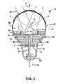
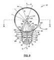
- FIG. 1is a cross-sectional view of a first embodiment of a lighting assembly according to the present disclosure
- FIG. 2Ais a top view of a circuit board according to the present disclosure
- FIG. 2Bis a top view of an alternate embodiment
- FIG. 2Cis a top view of another alternate embodiment
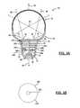
- FIG. 3Ais a cross-sectional view of the second embodiment of a lighting assembly according to the present disclosure.
- FIG. 3Bis a top view of a heat sink fin of FIG. 3A ;
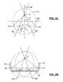
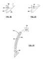
- FIG. 4Ais a side view of an ellipse
- FIG. 4Bis a cross-sectional view of a portion of an ellipsoid
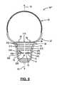
- FIG. 5is a cross-sectional view of a third embodiment of the present disclosure.
- FIG. 6is a cross-sectional view of a fourth embodiment of a light bulb according to the present disclosure.
- FIG. 7is cross-sectional view of a light bulb according to a fifth embodiment of the present disclosure.
- FIG. 8is a cross-sectional view of a sixth embodiment of the present disclosure.
- FIG. 8Ais an enlarged cross-sectional view of a light-shifter and filter
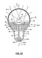
- FIG. 9is a cross-sectional view of a seventh embodiment of the present disclosure.
- FIG. 10is a cross-sectional view along line 10 - 10 of FIG. 9 ;
- FIG. 11is a cross-sectional view of another embodiment of the disclosure including reflectors as light redirectional elements
- FIG. 12is a cross-sectional view of a light assembly having surfaces as light redirection elements recessed within a circuit board;
- FIG. 12Ais an enlarged cross-sectional view of the light source portion of FIG. 12 .
- FIG. 12Bis an alternative cross-sectional view for the light source portion of FIG. 12 .
- FIG. 13is a cross-sectional view of a light assembly having a cylindrical control circuit therein;
- FIG. 14is a cross-sectional view of the control circuit of FIG. 13 ;
- FIG. 15is a cross-sectional view of a tubular light assembly according to the present disclosure.
- FIG. 16is a perspective view of the light assembly of FIG. 15 ;
- FIG. 17is a longitudinal view of the light assembly of FIG. 15 ;
- FIG. 18is a cross-sectional view of a tubular light assembly having an alternative embodiment to FIG. 15 ;
- FIG. 19Ais a cross-sectional view of a light assembly for use as a spotlight according to the present disclosure.
- FIG. 19Bis a partial view of the reflective surface of the reflector including circuit traces
- FIG. 20is an enlarged portion of an extension portion and an angular portion as an alternative to that illustrated in FIG. 19 ;
- FIG. 21is a cross-sectional view of the extension portion and angular portion having an alternative light redirection element
- FIG. 22is an enlarged cross-sectional view of a portion of the housing
- FIG. 23is an alternative embodiment of a light assembly having an alternative placement for a control circuit
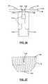
- FIG. 24is a side view of an alternative embodiment of the light assembly that includes a rectangular circuit board mounted within the base;
- FIG. 25is a cross-sectional view along line 25 - 25 of FIG. 24 illustrating a portion of the circuit board within the base;
- FIG. 26is a plan view of a control circuit board in relation to a light source circuit board
- FIG. 27is a side view of a lamp base formed according to the present disclosure.
- FIG. 28is a cutaway cross-sectional view of a heat sink assembly of FIG. 24 .
- control circuit boards and light source circuit boardsare implemented.
- various shapes of light redirection elements and heat sinksare also disclosed.
- Various combinations of heat sinks, control circuit boards, light source circuit boards, and shapes of the light assembliesmay be used.
- Various types of printed traces and materialsmay also be used interchangeably in the various embodiments of the light assembly.
- a lighting assemblyhaving various embodiments that include solid state light sources such as light-emitting diodes (LEDs) and solid state lasers with various wavelengths. Different numbers of light sources and different numbers of wavelengths may be used to form a desired light output depending upon the ultimate use for the light assembly.
- the light assemblyprovides an opto-thermal solution for a light device and uses multiple geometries to achieve the purpose.
- Light assembly 10may be rotationally symmetric around a longitudinal axis 12 .
- the light assembly 12includes a lamp base 14 , a housing 16 , and a cover 18 .
- the lamp base or base 14is used for providing electricity to the bulb.
- the base 14may have various shapes depending upon the application. The shapes may include a standard Edison base, or various other types of larger or smaller bases.
- the base 14may be various types including screw-in, clip-in or plug-in.
- the base 14may be at least partially made from metal for making electrical contact and may also be used for thermal heat conduction and dissipation.
- the base 14may also be made from material not limited to ceramic, thermally conductive plastic, plastic with molded circuit connectors, or the like.
- the housing 16is adjacent to the base 14 .
- the housing 16may be directly adjacent to the base 14 or have an intermediate portion therebetween.
- the housing 16may be formed of a metal or other heat-conductive material.
- a suitable metalis aluminum.
- the housing 16may be formed in various ways including stamping. Another way of forming the housing 16 includes injected-molded metals such as Zylor®. Thicksoform® molding may also be used.
- the housing 16may include a hyperboloidal-shaped portion 20 and another rotated conical section such as a partial ellipsoid or a partial paraboloid portion 22 .
- the housing 16may also be a free-form shape.
- the cover 18may be a partial spheroid or ellipsoid in shape.
- the cover 18may be formed of a transparent or translucent material such as glass or plastic.
- the cover 18may be designed to diffuse light and minimize backscattered light trapped within the light assembly.
- the cover 18may be coated with various materials to change the light characteristics such as wavelength or diffusion.
- An anti-reflective coatingmay also be applied to the inside of the cover 18 .
- a self-radiating materialmay also be used which is pumped by the light sources.
- the light assembly 10may be formed to have a high color rendering index and color perception in the dark.
- the housing 16 and cover 18form an enclosure around light sources 32 .
- the base 14may also be included as part of the enclosure.
- the light assembly 10includes a substrate or circuit board 30 used for supporting solid state light sources 32 .
- the circuit board 30may be planar (as illustrated) or curved as described below.
- the circuit board 30may be thermally conductive and may also be made from heat sink material. Solder pads of the light sources may be thermally and/or electrically coupled to radially-oriented copper sectors or circular conductive elements over-molded onto a plastic base to assist in heat conduction. In any of the embodiments below, the circuit board 30 may be part of the heat sink.
- the light sources 32have a high lumen-per-watt output.
- the light sources 32may generate the same wavelength of light or may generate different wavelengths of light.
- the light sources 32may also be solid state lasers.
- the solid state lasersmay generate collimated light.
- the light sources 32may also be light-emitted diodes.
- a combination of different light sources generating different wavelengthsmay be used for obtaining a desired spectrum. Examples of suitable wavelengths include ultraviolet or blue (e.g. 450-470 nm). Multiple light sources 32 generating the same wavelengths may also be used.
- the light sources 32such as light-emitting diodes generate low-angle light 34 and high-angle light 36 . High-angle light 36 is directed out through the cover 18 .
- the low-angle lightis light not directed in a working direction. Low angle light is usually wasted since it is not directed out of the fixture into which the light assembly is coupled.
- the low-angle light 34is redirected out of the cover 18 using a reflector 40 .
- the reflector 40may be various shapes including a paraboloid, ellipsoid, or free-formed shape.
- the reflector 40may also be shaped to direct the light from the light sources 32 to a central or common point 42 .
- the reflector 40may have a coating for wavelength or energy shifting and spectral selection. Coating one or both of the cover 18 and the reflector 40 may be performed. Multiple coatings may also be used.
- the common point 42may be the center of the spheroid or ellipsoid of the cover 18 .
- the circuit board 30may be in direct contact with a heat sink 50 or a circuit board as described below.
- the heat sink 50may include a plurality of fins 52 that form layers and extend in a perpendicular direction to the longitudinal axis 12 of the light assembly 10 .
- the fins 52may be spaced apart to allow heat to be dissipated therefrom.
- the heat sink 50may also include a central portion 54 .
- the central portion 54may contact the circuit board 30 or a central control circuit board as described below.
- the central portion 54may be generally cylindrical in shape with an opening 114 therethrough and the fins 52 extending therefrom.
- the opening 114 therethroughmay include a heat stake 56 disposed therein.
- the heat stake 56may contact the circuit board 30 and thermally conduct heat to the central portion 54 and ultimately to the fins 52 .
- the heat stake 56may also thermally conduct heat to the lamp base 14 .
- the heat stake 56may also receive heat from fins 52 .
- the fins 52may be planar in shape.
- the planes of the fins 52may be perpendicular to the longitudinal axis and contact the housing 16 . It may not be necessary for direct contact between the fins 52 and the housing 16 depending on various design factors. However, the outer edges of the fins 52 of the heat sink 50 may contact the housing 16 .
- the housing 16may thus conduct heat away from the light sources 32 of the circuit board for dissipation outside the light assembly.
- Additional fins 58may be disposed above the circuit board 30 .
- the additional fins 58may also be in thermal communication with the circuit board 30 .
- the fins 58may also support the reflectors 40 . Fins 58 may also be in direct or thermal contact with the housing 16 .
- a control circuit board 70may also be included within the light assembly 10 .
- the control circuit board 70is illustrated as planar and circular. Different embodiments of the circuit board 70 may be implemented, such as a cylindrical or longitudinally-oriented circuit board.
- the circuit board 70may be various shapes.
- the control circuit board 70may include various control chips 72 that may be used for controlling various functions of the light sources 32 .
- the control chips 72may include an alternating current to direct current converter, a dimming circuit, a remote control circuit, discrete components such as resistors and capacitors, and a power circuit.
- the various functionsmay be included on an application-specific integrated circuit. Although only one control circuit board 70 is illustrated, multiple circuit boards may be provided within the light assembly 10 .
- the circuit board 70may also be in thermal communication with the heat stake 56 . The heat stake 56 may thus conduct heat away from the circuit board 70 toward the lamp base 14 or through the heat stake 56 to the central portion 54 and to the fins 52 .
- the circuit board 30includes the plurality of light sources 32 thereon.
- the circuit board 30includes a radial outward thermal path 110 and a radially inward thermal path 112 .
- the opening 114may be provided through the circuit board 30 .
- the opening 114as was illustrated in FIG. 1 , may have the heat stake 56 therethrough.
- the opening 114may also remain open to allow air flow circulation within the light assembly 10 .
- the opening 114may be replaced by more than one opening.
- the openingsmay be sized to receive a wire or wires from a control circuit board to make an electrical connection to the circuit board 30 . Such embodiments will be described below.
- Thermal vias 116may be provided throughout the circuit board 30 to allow a thermal path to the heat sink 50 . As is illustrated, the thermal vias 116 are generally laid out in a triangular or pie-piece arrangement but do not interfere with the thermal paths 110 and 112 . Thermal vias 116 may be directly under the light sources.
- the circuit board 30may be made out of various materials to form a thermally-conductive substrate.
- the solder pads of the light sourcesmay be connected to radial-oriented copper sectors or circular conductive elements that are over-molded into a plastic base to conduct heat away from the light sources. By removing the heat from the area of the light sources, the lifetime of the light assembly 10 may be extended.
- the circuit board 30may be formed from two-sided FR4 material, heat sink material, or the like. If the board material is electrically conductive, the electrical traces may be formed on a non-conductive layer that is formed on the electrically conductive surface of the circuit board.
- the circuit board 30 ′may include a plurality of circuit trace sectors 130 and 132 that are coupled to alternate voltage sources to power the light sources 32 .
- the sectorsare separated by a non-conductive gap 134 .
- the light sources 32may be electrically coupled to alternate sectors 130 , 132 .
- the light sources 32may be soldered or otherwise electrically mounted to the two sectors 130 , 132 .
- Each sector 130 , 132may be disposed on a non-conductive circuit board 30 ′.
- the circuit board 30 ′may also be formed of a heat sink material. Should the heat sink material be electrically conductive, a non-conductive pad or layer may be placed between the sectors 130 , 132 and the circuit board 30 ′.
- the opening 114is illustrated as a circle.
- the opening 114may also be replaced by two smaller openings for coupling a wire or wires from a control circuit board thereto. Such an embodiment will be described further below.
- the circuit board 30 ′′includes the light sources 32 that are spaced apart by circuit traces 140 and 142 .
- the circuit traces 140 and 142may have different voltages used for activating or enabling the light sources 32 .
- the circuit traces 140 , 142may be printed on a substrate such as a heat sink substrate. Electrical connections may be made from the control circuit board.
- the housing 16 ′may include the hyperboloid portion 20 as illustrated in FIG. 1 and an ellipsoid portion 22 ′.
- the ellipsoid portion 22 ′may be used as a reflector to redirect low-angle light 34 emitted from the light-emitting sources 32 .
- the inside of the housing 16 ′may be used as the reflective surface.
- the inside surface of the housing 16 ′may be anodized aluminum or another reflective surface. High-angle light 36 is transmitted directly through the cover 18 .
- the common point 42may be one focal point of the ellipsoid while the ring of light sources 32 may form the second focal point of the ellipsoid. Because a ring of light sources is used as the second focal point of the ellipsoid, the ellipsoid may be referred to as an offset ellipsoid. The construction of the ellipsoid will be further described below.
- a heat sink 210may be constructed in a different manner to that illustrated in FIG. 1 . However, it should be recognized that the construction of the heat sink 210 in FIG. 1 may be incorporated into the optical configuration of FIG. 3 .
- a plurality of heat-sink fins 212is disposed within the light assembly 10 ′.
- the heat sink 210may comprise a plurality of disks with opening 220 therethrough as is best shown in FIG. 3B .
- Each heat sink fin 212may resemble a washer.
- the heat-sink fins 212may be in thermal communication with the heat stake 56 and the paraboloidal or hyperboloidal portion 16 ′ of the housing 20 .
- Each heat-sink fin 212may conduct heat isotropically using materials such as aluminum or copper.
- the heat-sink fins 212may also conduct heat anistropically using materials such as graphite, aluminum and magnesium.
- the outer diameter of the heat sink 210varies according to the shape of the hyperboloidal portion 16 .
- the outer edge 213 of the fins 212 of the heat sink 210may contact the housing 16 ′.
- the contour or outer shape of the diskis hyperboloidal.
- the opening 220may receive the heat stake 56 or may have the heat stake 56 removed as will be described below.
- the light sources 32may also be mounted on a heat sink fin 212 .
- the heat sink fin 212may have conductive traces thereon to form the electrical interconnections using part of the heat sink to house and interconnect the light sources. This may be done in any of the embodiments set forth herein.
- Notches 240 and 242may snap-fit the heat-sink fins 212 within the housing.
- One lower notch 240 and one upper notch 242are illustrated for simplicity.
- each of the heat-sink fins 212 and the circuit board 30may be secured to the housing in a similar manner. Because the heat-sink fins 212 and the circuit board 30 may be flexible, snap-fitting the circuit board 30 and the heat-sink fins 212 into place is possible. Of course, other methods for securing the heat-sink fins 212 and the circuit board 30 may be used. These may include securing the circuit board and heat-sink fins to the heat stake 56 and securing the heat stake 56 to the lamp base 14 , using mechanical fasteners or adhesives.
- the ellipsoidhas two focal points: F 1 and F 2 .
- the ellipsoidalso has a center point C.
- the major axis 310 of the ellipse 308is the line that includes F 1 and F 2 .
- the minor axis 312is perpendicular to the major axis 310 and intersects the major axis 310 at point C.
- the focal points corresponding to the light sources 32are moved outward from the major axis 310 and are shifted or rotated about the focal point F 1 .
- the ellipsoidis then rotated and a portion of the surface of the ellipsoid is used as a reflective surface.
- the angle 312may be various angles corresponding to the desired overall geometry of the device. In an ellipse, light generated at point F 2 will reflect from a reflector at the outer surface 314 of the ellipse and intersect at point F 1 .
- the shifted or offset ellipsoidwill reflect light from the focal points F 2 ′ and F 2 ′′ to intersect on the focal point F 1 .
- the focal points F 2 ′ and F 2 ′′are on a ring of light sources 32 whose low-angle light is reflected from the shifted ellipsoid surface and the light is directed to focal point F 1 .
- the construction of the ellipsoidcan thus be seen in FIG. 4B since the focal point F 2 now becomes the ring that includes F 2 ′ and F 2 ′′.
- the circuit board 30may be coupled to the elliptical portion 22 ′.
- the heat sink 210 of a light assembly corresponding to that illustrated in FIG. 1 or 3 Amay be used.
- a stand-off or plurality of stand-offs 410is constructed to support a light-shifting element 412 .
- the low-angle light 34 from the light sources 32is directed toward the common point 42 .
- the common point 42may be the center of the cover portion 18 and a focal point of the ellipsoidal portion 22 ′.
- the light-shifting element 412may be coated with a light-frequency (energy) shifting material so that low-angle light is provided with a different light characteristic which is added to the direct light from the light sources 32 to form a desired output spectrum of light frequencies.
- the light-shifting element 42may be coated within phosphors, nano-phosphors or fluorescent dyes to achieve a desired spectral distribution.
- One exampleis the use of blue light sources or lasers that, when the blue light comes into contact within the light or energy-shifting material, another color such as white light may be emitted.
- the energymay be absorbed by the light-shifting material and re-radiated in various directions as indicated by the arrows 414 .
- One light raymay be scattered in various directions with a wavelength different from the wavelength of the light sources 32 .
- the light-shifting element 412may be solid material such as metal so that light reflects therefrom.
- the light-shifting element 412may be spherical or other shapes.
- FIG. 6an embodiment of light assembly 10 ′′ similar to FIG. 3A is illustrated except that the heat stake 56 is removed from the openings 114 in each heat sink fin 212 .
- the openings 114are left open within the fins 212 of the heat sink so that air may circulate within the light assembly 10 ′′.
- the openings 114may also align with an opening 220 in the circuit board 70 so that the air may circulate to dissipate heat within the light assembly 10 ′′.
- a light-shifting elementsuch as a dome 510 is illustrated.
- the dome 510may include the frequency-shifting or diffusing material such as those described above.
- a film or coatingmay be applied to the dome 510 to provide light-shifting or diffusion of the frequencies of the light.
- any of the embodiments set forth above or belowmay include a light-shifting element such as a dome 510 .
- the dome 510may be made out of various materials including a light filter layer 512 and a light-shifting layer 514 .
- the light filter layer 512may be used to pass a wavelength of light therethrough. The wavelength may correspond to the wavelength of the light source 32 . For example, should the light source 32 be a blue laser or blue LED, the filter 512 may pass the blue light therethrough.
- the shifting layer 514may shift the wavelength of light to another wavelength besides blue. For example, the blue wavelength may activate the light-shifting element 514 to generate white light therefrom. The white light may be generated in a straight line or may be scattered.
- Scattering lightis indicated by the arrows 516 .
- Lightmay be scattered back toward the light sources 32 as well.
- the boundary between the filter layer 512 and the light-shifting layer 514may reflect back all but the blue light.
- the light reflected from the boundary between the filter 512 and the light-shifting layer 514may ultimately exit through the cover 18 .
- the embodiment of FIG. 7also includes perforations 520 within or through the housing 16 ′.
- the perforations 520may be openings adjacent to the fins 52 to provide an external conductive path to dissipate heat from the light assembly 10 iv .
- the perforations 520may be stamped or otherwise formed within or through the housing 16 ′ during manufacturing.
- the light assembly 10 ivdoes not require a vacuum as does an incandescent bulb. Any embodiment described above or below may include perforations 520 .
- a light-shifting elementsuch as a film 600 is disposed across the cover 18 .
- the amount of light-shifting material on or within the film 600may change across its length according to a gradient.
- the gradientmay include more light shifting toward the middle or center 602 of the film and less light shifting toward the cover 18 . That is, the light-shifting rate may be a first rate adjacent to the cover and a second rate more than the first rate near the center of the cover.
- the position of the film relative to the circuit board 30may vary along the axis 12 depending on the amount of light to be shifted. If less light is desired to be shifted, the film may be suspended closer to the top of the cover 18 away from base 14 . If all the light is desired to be shifted, the light-shifter 600 may be suspended across the cover 18 or the housing 16 near the junction of the housing 16 ′ and the cover 18 at point 604 .
- the light-shifter 600may be formed on a filter 604 for a wavelength such as blue.
- the light-shifter 600or more properly the particles or elements within the light-shifter, may scatter light in various directions including in the direction of the light source. If the filter has the same filter characteristics as the light source, light will be transmitted from the light source through the filter. Light radiated back toward the light source will be reflected at the light-shifter 600 /filter 606 , interface 607 and directed away from the light source. Blue light or the light transmission wavelength of the filter will pass back through the filter toward the light source. As is illustrated, light 608 from the light source is scattered as indicated by arrows 609 .
- the light entering the filter 606 that was scattered from the light-shifter 600is in the same wavelength of the light sources 32 .
- the light reflected at the interface 607may be wavelengths other than the wavelength of the wavelength-passing material or band-pass filter 606 .
- the filter 606may be a band-pass filter that passes the wavelength of light from the light source 32 therethrough which is scattered by the light-shifter 600 . This is similar to that described above with respect to FIG. 7 .
- the combination of the light-shifter 600 and filter 606may be referred to as a pump; in this example, a blue pump.
- a circuit board 610may have a curved or partial spheroidal shape.
- the circuit board 610may be a conventional fiberglass circuit board substrate or a metal substrate with an isolation layer thereon. Circuit traces may be formed on the isolation layer then insulated. For example, an aluminum substrate with an anodized layer may have circuit traces thereon. The circuit traces may be coated with an insulator.
- the circuit board 610may be planar then heated and molded into the desired shape.
- the circuit board 610includes light sources 612 thereon.
- the light sources 612may be disposed in a circle or ring 613 as illustrated above and in FIG. 10 .
- the circle 613may intersect each light source 612 .
- the circle 613may be disposed on a plane perpendicular to the longitudinal axis 12 of the light assembly 10 vi .
- the cover portion 18may be a partial spheroid as mentioned above.
- the radius R 1 of the spheroid of the cover portion 18 and the radius R 2 of the circuit board 610may have the same radius.
- the radii R 1 and R 2may also be the same.
- the cover portion 18may also be an ellipsoid.
- the center of the ellipsoidmay correspond to the center 616 of the cover portion 18 .
- a light shifter 614may be disposed at a center 616 of the spheroid of the circuit board 610 .
- the light shifter 614may be similar to that illustrated in FIG. 5 . That is, the light shifter 614 may have a light frequency shifting coating or film 617 thereon for shifting at least a portion of the light that travels through the light shifter 614 and is eventually transmitted through the cover 18 .
- FIG. 9may be formed as in FIG. 4A with F 1 corresponding to 616 and F 2 ′ and F 2 ′′ corresponding to light sources 612 .
- Each light source 612may include a redirection element such as a lens 620 disposed in the light path for focusing the light from the light source 612 to the center 616 .
- the lens 620may be a converging lens.
- the light sources 612may be parallel to a tangential line 618 to the surface of the spheroid of the circuit board 610 .
- Light emitted along the center axis 624 of the light sourceintersects the point 616 and light shifter 614 .
- the center axisis perpendicular to the tangential line 618 .
- any light emitted from the light source 612may converge at the center point 616 .
- the lightis shifted by the light shifter 614 .
- Each lensmay also be coated to provide light-shifting properties as well. Light sources using ultraviolet or blue light may thus be converted into various frequencies to provide white light.
- the light shifter 614may be supported from the circuit board 610 using a stand-off 630 .
- the stand-off 630may also be mounted to the stake 56 or directly to the circuit board 610 as illustrated.
- the reflectors 640may have a surface that is a portion of an ellipsoid or a portion of a paraboloid.
- the partially ellipsoidal shapemay surround a portion of each light source 612 .
- the light source 612may be placed at one focal point of a spheroid, and the second focal point of the spheroid for the reflector 640 may be point 616 .
- F 1would correspond to 616
- F 2 ′would correspond to one of the light sources 612 .
- Each light sourcemay have a separate reflector 640 .
- FIGS. 12 , 12 A and 12 Ban embodiment similar to FIGS. 9 and 11 is illustrated.
- the reflectors 640 illustrated in FIG. 11have been replaced by a recess 650 disposed within the circuit board 610 .
- the recess 650 within a circuit boardmay be an opening 650 through the circuit board 610 or a recess partially through the circuit board 610 as illustrated in FIG. 12B .
- the opening 650may have a surface 652 that has a reflector 654 adjacent thereto.
- the reflectorcould be a separate component of a metalized edge of the opening 650 .
- the reflector 654may be a metalized surface of the circuit board that has an ellipsoidal cross-sectional or paraboloidal shape.
- the metalized surface 614may be disposed on an edge 652 of the circuit board 610 .
- the light source 612may be affixed to a bottom surface 654 of the opening 650 of the circuit board 610 if the opening 650 does not extend fully through the circuit board 610 . As illustrated in FIG. 12B , the light sources 612 may affix to the circuit board 610 or the reflective surface 654 if the opening 650 extends through the circuit board 610 . Light from the light sources 612 reflect from the reflective surface 654 toward the point 616 . Light traveling toward point 616 is reflected by the light shifter 614 .
- the circuit board 70 ′may replace the heat stake 56 within the light assembly although the openings 708 through the heat-sink fins may be widened.
- the control circuit board 70 ′may include various components depending upon the application. One component may be an AC to DC converter 710 . Other discrete components such as a plurality of resistors 712 and capacitors 714 may also be included on the control circuit board 70 ′.
- the control circuit board 70 ′may include input leads 716 and 718 that may be coupled to the AC circuit. Leads 720 and 722 may be coupled to a DC circuit. The leads 716 , 718 may be coupled through a metallic base 14 of the circuit board 701 and provide AC power to the circuit. The leads 720 , 722 may ultimately be coupled to the circuit board 30 and to the light sources 32 .
- the opening 708 between the control circuit board 701 and the heat-sink fins 212may be constant.
- Small fingers 720may extend from the heat-sink fins 212 to support the circuit board 70 ′.
- the fingers 720may be large enough to provide axial support but small enough to provide airflow between the circuit board 70 ′ and fins 212 .
- control circuit board 70is illustrated in a cross-sectional view taken perpendicular to the longitudinal axis 12 of the light assembly.
- the components 710 , 712 , and 714may be disposed on a circuit board 730 that has been formed in a cylindrical manner.
- the circuit board 730may be various types of circuit boards, including a fiberglass circuit board or a metal substrate as described above.
- the circuit board 730may be filled with epoxy 732 after the circuit board is formed. That is, the circuit board 70 ′ may be populated and formed into a cylindrical shape.
- the cylindrical shapemay be formed before or after the device is populated with the electrical components. Substantially all of the length of the cylindrical shape may be filled with an epoxy.
- the circuit board 730defines an interior portion and an exterior portion of the control circuit board 70 ′.
- the electrical components 710 - 714are located within the interior of the cylindrical wall formed by the control circuit board 70 ′.
- the interior portionis filled with the epoxy 732 .
- FIG. 14shows the opening or space between the control circuit board 70 ′ and the heat-sink fins 212 . Fingers 720 are also illustrated for axially supporting the control circuit board 70 ′.
- a light-shifting element on the cover 18 or in various locations such as that illustrated in FIG. 5 , FIG. 7 , FIG. 8 and FIG. 9may also be incorporated within the light assembly illustrated in FIGS. 13 and 14 .
- the tubular light assembly 810includes a reflective surface 812 .
- the reflective surface 812may be parabolic in shape. That is, the reflective surface 812 may be a parabolic cylinder.
- the light assembly 810includes a longitudinal axis 814 .
- Light sources 820may be disposed along the longitudinal axis 814 . Light from the light sources 820 is directed toward the reflective surface 812 .
- the reflective surface 812may be parabolic in shape.
- the parabolic shapemay have a focal line coincident with the longitudinal axis 814 of the light assembly 810 .
- Light rays 830 reflecting from the reflective surface 812are collimated. In a longitudinal direction the light rays 830 are diffused.
- a light-shifting element 832may also be disposed within the light assembly 810 . As is illustrated in FIGS. 15 , 16 , and 17 , the light-shifting element 832 may comprise a film that extends from one edge of the reflecting surface 812 to another edge of the reflecting surface 812 across the light assembly 810 . The light-shifting element 832 may be coupled to the reflective surface or to a housing 834 . The light-shifting element 832 may also be coupled to a cover 842 .
- the light-shifting element 832may have a light-selective (band-pass filtering or dichroic) film 833 associated therewith. That is, a material 833 may have a wavelength transmissive to the light source wavelength (such as blue or UV). The interface between the light-shifting element 832 and the film 833 will reflect wavelengths other than the selected wavelength as described above in FIGS. 7 and 8 .
- the housing 834may be a cylindrical housing that has a half-circle cross-section.
- the housing 834may be a separate component as illustrated in FIG. 15 or may be a single structure that has an outer surface and the inner surface being the reflective surface 812 as illustrated in FIG. 18 .
- the materialsmay be metal, plastic, metal on plastic, or combinations.
- a control circuit 838may be used to control the power to the light sources 820 . More than one control circuit 838 may be located within a tubular light assembly 810 . For example, a control circuit 838 may be located at each longitudinal end of the tubular light assembly 810 .
- the control circuit 838may have circuit traces 840 extending therefrom for providing power to the light sources 820 .
- the circuit traces 840may be formed on the surface of the light-shifting element 832 .
- the traces 840may also be separate wires coupled to the light sources from the control circuit 838 .
- the light-shifting element 832may be located across a diameter of light assembly 810 .
- the light sources 820may be located at a center point of the tubular assembly that corresponds with the longitudinal axis 814 .
- the light-shifting element 832may thus define a plane that extends along the length of the light assembly 810 .
- the light-shifting element 832may also be located on a cover 842 .
- the cover 842may also be cylindrical or partially cylindrical in shape.
- the cover 842may also have a diffusive coating for diffusing the light in various directions.
- the light sources 820are not located at the longitudinal axis 814 of the light assembly 810 ′.
- the light sources 820may be suspended above the reflective surface 812 using supports or legs 846 .
- the legs 846may extend from the housing 834 or the reflective surface 812 .
- the reflective surface 812may also be parabolic in cross-section or a parabolic cylinder in three dimensions.
- the parabolic cylinder 812may have a focal line 850 that intersects the light sources 820 . Thus, light emitted from the light sources 820 is directed toward the parabolic surface 812 and is collimated.
- legs 846may be used to suspend a light source. Each light source may be suspended or positioned by one or more legs 846 .
- the light assembly 810 ′may also include a cover 842 as described above.
- the light assembly 810 ′may also include a separate housing 834 and a separate parabolic surface 812 . It should be noted that the light source suspended by legs illustrated in the light assembly 810 ′ could also be used in the light assembly 810 illustrated in FIGS. 15 , 16 , and 17 .
- a light-shifting element 832is illustrated in the light assembly 810 which extends across the light assembly, a light-shifting element may be formed on the inner surface 854 or the outer surface 856 of the cover 842 . Most likely, the light-shifting surface will be on the inner surface 854 of the cover 852 in a commercial embodiment.
- the light assembly 910is a spot light or down light.
- the light assembly 910includes a base 912 and a housing 914 .
- the base portion 912may be screwed or clipped into an electrical receptacle.
- the housing 914is used for reflecting light as will be described below.
- the light assembly 910may also include a lens portion 916 .
- the lens portion 916may comprise light diffusers or a smooth surface.
- the lens portion 916may have a film.
- the housing 914may have light sources 920 attached thereto.
- the light sources 920may be spaced around the light assembly 910 in a position opposite to the base 912 .
- the light sources 920may generate various wavelengths of light including blue. All or some of the light sources may emit the same wavelength of light. In this example, each of the light sources 920 generates blue light.
- the housing 914may include an extension portion 926 for coupling the light sources 920 thereto.
- the extension 926 and the angular portion 924may have a fixed relationship such as 45 degrees. The angle of the fixed relationship between the extension 926 and the angular portion 924 is fixed so that light is reflected as described below.
- the housing portion 914may be parabolic in shape. The construction of the housing 914 will be described further below. However, the interior of the light assembly 910 at the housing 914 may include a reflective surface 930 . The reflective surface 930 has a focal point 934 .
- the light sources 920may generate collimated light or have light redirection elements that generate collimated light as will be illustrated in FIGS. 20 and 21 .
- the collimated lightis directed to the angular portion 924 . When the collimated light and the angular portion 924 are at 45 degrees, the collimated light is reflected at an angle parallel to the longitudinal axis 936 of the light assembly 910 . Light reflected in a direction parallel to the longitudinal axis 936 reflects from the reflective surface 930 toward the focal point 934 .
- a light-shifting element 940is coupled within the light assembly 910 .
- the light-shifting element 940is fixedly coupled to the base 912 .
- the light-shifting elementmay also be coupled to the housing 914 .
- the light-shifting element 940includes a first cylindrical portion 942 , a second cylindrical portion 944 , and a spheroidal portion 946 .
- the first cylindrical portion 942is adjacent to the base or housing 914 .
- the spheroidal portion 946has a center point that is coincident with the focal point 934 .
- the longitudinal axis 936is the longitudinal axis of the first cylindrical portion 942 and the second cylindrical portion 944 and intersects the center 934 of the spheroid 946 .
- the light-shifting element 940may be covered with a light-shifting or energy-conversion material.
- the light-shifting materialmay create white light from blue light.
- the collimated light that is redirected from the angular portion 924reflects from the light-shifting element 940 and is also wavelength-shifted at the light-shifting element 940 .
- the light reflected from the light-shifting element 940is redirected to the reflective surface 930 of the housing 914 which redirects the light through the lens portion 916 .
- the angular portion 924may be metallic or light non-transmissive.
- the angular portion 924may also be a selectively reflective surface.
- Glass or plasticmay be suitable wavelength selectively reflective surfaces. Different wavelengths of the light may reflect others and may pass therethrough.
- the wavelength selectively reflective surfacemay be formed by applying various types of materials.
- the angular portion 924may be formed of a glass or plastic material that reflects the wavelength emitted by the light sources 920 while allowing wavelengths formed by the light-shifting element 940 to pass through. In the example above, the light sources 920 emitted light at a blue wavelength.
- the light-shifting element 940converted the blue wavelength to white light which may be passed through the angular portion when leaving the light assembly 910 .
- the housing 914may be made from a plastic material coated with an electrically conductive or electrically reflective material. If the material is both electrically conductive and reflective, the entire surface of the housing 914 may be coated with the material and portions may be removed to form gaps 947 therebetween. The gaps 947 may thus form traces 948 that may be powered by the control circuit 944 at different voltages to provide a voltage difference for operating the light source 920 .
- a plurality of light sources 920may be disposed around the circumference of the light assembly 910 . Thus, a pair of conductors 948 may be provided for each light source 920 .
- the size of the tracesin terms of width, may vary depending upon the various requirements.
- the size of the gaps 947is reduced so that reflective material removal is minimized.
- the reflectormay have the greatest amount of reflectivity and thus an increased light output of the light assembly.
- a lens 950is used as a light redirection element.
- the lens 950collimates light in a direction perpendicular to the longitudinal axis 936 of the light assembly 910 illustrated in FIG. 19 .
- the light reflected from the angular portion 924is reflected in a direction parallel to the longitudinal axis 936 .
- the reflector 952may be a parabolic or paraboloid shaped reflector that surrounds or nearly surrounds the light source 920 .
- Light reflected from the parabolic reflector 952is collimated in a direction perpendicular to the longitudinal axis 936 .
- Light reflected by the angular portion 924is perpendicular to the longitudinal axis 936 .
- the housing 914may be formed of various materials and have a circuit trace 960 therein.
- the circuit trace 960may be embedded within the housing 914 . That is, the housing 914 may be made of a plastic material and a circuit trace 960 may be embedded within the plastic material.
- the circuit trace 960couples the control circuit 944 to the light sources 920 . Two wires from the control circuit 944 to each of the light sources 920 may be embedded within the housing. Of course, other ways to provide power to the light sources may be used.
- the light assembly 1010includes a lamp base 1014 .
- the lamp base 1014extends a predetermined distance from a bottom portion 1016 of the light assembly.
- the lamp base 1014may be, for example, an Edison lamp base.
- the lamp base 1014may include threads or other mechanical structures for affixing the lamp assembly 1010 within a socket (not illustrated).
- the lamp base 1014defines a volume therein.
- the control circuit 1012may be disposed on one or more circuit boards that include drivers for driving the light sources.
- the control circuit 1012may be coupled to the circuit board 30 having the light sources 32 in various manners including a direct wire or a wire within the housing of the light assembly 1010 or within the heat stake 56 .
- the control circuit 1014may also include alternating current to direct current circuit and other components.
- the control circuit 1012may be partially within the volume of the lamp base.
- the control circuit 1012may also be disposed entirely within the volume defined within the lamp base 1014 .
- the control circuit 1012may also be epoxy encapsulated within the volume of the lamp base 1014 .
- FIG. 1Although a light assembly configuration similar to FIG. 1 is illustrated, the light configurations illustrated in the other figures may be incorporated therein. That is, a control circuit 1012 disposed within a lamp base volume may be incorporated into any of the embodiments above.
- FIGS. 24 , 25 and 26another embodiment of a light assembly 1100 is illustrated. This embodiment is similar to that illustrated in FIG. 13 above and thus common components will be labeled the same.
- the control circuit board 1110may include various electrical components forming the controls for the light assembly.
- the electrical components 1112may be affixed to one or more sides of the circuit board 1110 .
- the components 1112may be various types of components as those described above, including an AC to DC converter, resistors, electrical chips, capacitors, and other elements.
- the circuit board 1110may fit within the base 14 .
- the fitmay be an interference fit between the base 14 and the circuit board 1110 .
- a pair of grooves 1114may be formed laterally across the base 14 from each other so that the circuit board 1110 may be accepted therein.
- the circuit board 1112may include edge connectors 1116 , 1118 for electrically coupling to opposite polarities within the base 14 .
- the interference fit within the grooves 1114may be used to insure an electrical connection between the edge connectors 1116 , 1118 and contacts 1120 disposed within the grooves 1114 .
- the base 14may be a standard Edison base that, in combination with the other elements, forms a form function independent lighting source. That is, the base 14 and circuit board 1110 may be used with various light source configurations and optical arrangements.
- the circuit board 1110may include wires 1130 extending therefrom.
- the wires 1130may be used to provide power to the light sources 32 on the circuit board 30 .
- Solder material 1132may be used to join the wires 1130 to circuit traces 1134 disposed on the circuit board 30 .
- other materials for joining the wires 1130 to the circuit traces 1134may be evident to those skilled in the art.
- conductive inks or adhesivesmay also be used.
- Wire bondingis another method for joining the wires 1130 to the circuit traces 1134 .
- the embodiment illustrated in FIGS. 24-26has a manufacturing advantage.
- the circuit base 14may be formed and the circuit board may be populated.
- the circuit board 1110may then be inserted into the grooves 1114 so that the contacts 1120 are electrically coupled to the edge connectors 1116 and 1118 .
- Various configurations of electrical contactsmay be used. What is important is that electricity is provided from the base 14 to the control circuit board 1110 .
- Heat-sink fins 1140may have a center portion 1142 that joins the heat-sink fins 1140 together.
- the central portion 1142may also extend upward to the circuit board 30 so that the circuit board 30 becomes or is also part of the heat sinking process.
- the heat sink 210may be pre-manufactured by assembling the parts or molding the components integrally.
- the light sources 32may be electrically joined to the circuit board 30 prior to insertion within the light assembly 1100 .
- the assembly that consists of the circuit board 30 and the heat-sink fins 1140may be placed upon the circuit board so that the wires 1130 extend through openings 1172 within the circuit board 30 .
- the wires 1130may then be electrically coupled to the traces 1134 on the circuit board 30 .
- the cover 18may then be placed over the light assembly and affixed to the housing 16 ′.
- the base 14may include an electrical contact 1160 thereon.
- the contact 1160provides sufficient electrical contact with the socket into which the bulb is placed.
- Another electrical contact(not shown) may be coupled to the bottom portion or bottom contact 1162 .
- the electrical contact 1160 and the contact (not shown) in communication with the bottom portion 1162may have opposite polarities in the AC circuit.
- the opposite polarities of the contacts 1160 and 1162may provide power to the circuit board 1110 .
- the base 14may be a screw-in base having threads 1164 . However, various types of bases may be used as described above.
- the contact 1160is electrically connected to one of the contacts 1120 .
- the wire or trace in electrical communication with contact 1162is in communication with the opposite contact 1120 .
- the heat sinkincludes fins 1140 along with the center portion 1142 as is illustrated.
- the circuit board 30is formed from the same material as the heat-sink fins.
- the circuit traces 1134are used to power the light sources 32 .
- the circuit board 30may be a separate component or integrally molded with the heat-sink fins.
- An opening 1170may be sized to receive the circuit board therein.
- An opening 1172 in the top of the circuit board 30may be used to receive the wires 1130 from the circuit board 30 .
- the circuit board 30may be formed in the various manners described above in FIGS. 2A-2C with non-conductive portions and the circuit traces 1134 thereon. Because only half of the heat sink assembly is illustrated, another opening (not illustrated) may be provided for the wires 1130 having opposite polarity.
- various components using the above embodimentsmay be interchangeable.
- various light-shifting mechanismsmay be used to change the wavelength of light from one wavelength to another wavelength.
- the various housing shapes and cover shapesmay also be interchangeable.
- various lamp basesmay also be used.
- the control circuitmay have many different types of embodiments for controlling the light-emitting diodes or other light sources. Various types and shapes of control circuits may be used in each of the embodiments.
- the heat sinks and light-emitting diodesmay also have various configurations as described above.
- the heat sinksmay be washer-like structures or may be an integrated structure as illustrated in FIG. 28 .
- the heat sinkmay also be integrated with the light source circuit board 30 as illustrated in FIG. 28 .
- the light source circuit board 30may have various different embodiments including those illustrated in FIGS. 2A-2B . Such configurations may also be included within the heat sink configuration illustrated in FIG. 28 . Other methods of performing heat dissipation, such as those illustrated in FIG. 3A using a heat stake and other embodiments using no heat stake, may be incorporated with various shapes of light assemblies. Also, the perforations 520 illustrated above may also be incorporated into any of the embodiments described above.
Landscapes
- Engineering & Computer Science (AREA)
- General Engineering & Computer Science (AREA)
- Physics & Mathematics (AREA)
- Spectroscopy & Molecular Physics (AREA)
- Microelectronics & Electronic Packaging (AREA)
- Optics & Photonics (AREA)
- Geometry (AREA)
- Arrangement Of Elements, Cooling, Sealing, Or The Like Of Lighting Devices (AREA)
- Non-Portable Lighting Devices Or Systems Thereof (AREA)
- Fastening Of Light Sources Or Lamp Holders (AREA)
Abstract
Description
Claims (15)
Priority Applications (24)
| Application Number | Priority Date | Filing Date | Title |
|---|---|---|---|
| US12/817,807US8186852B2 (en) | 2009-06-24 | 2010-06-17 | Opto-thermal solution for multi-utility solid state lighting device using conic section geometries |
| CN201510766045.4ACN105402616B (en) | 2009-06-24 | 2010-06-22 | Light Assembly |
| JP2012517656AJP5759455B2 (en) | 2009-06-24 | 2010-06-22 | Thermo-optic solution for multi-purpose solid-state lighting devices using conic curves |
| EP17162916.5AEP3208534A1 (en) | 2009-06-24 | 2010-06-22 | Light assembly |
| CN201510767967.7ACN105299484B (en) | 2009-06-24 | 2010-06-22 | Luminescence component |
| BRPI1014839ABRPI1014839A2 (en) | 2009-06-24 | 2010-06-22 | opto-thermal solution for multiple utility solid state lighting using conical section geometries. |
| CN201080028308.7ACN102483213B (en) | 2009-06-24 | 2010-06-22 | Photothermal solutions for multifunctional solid-state light-emitting devices using conic geometry |
| PCT/US2010/039509WO2011005526A2 (en) | 2009-06-24 | 2010-06-22 | Opto-thermal solution for multi-utility solid state lighting device using conic section geometries |
| CN201410559918.XACN104595851A (en) | 2009-06-24 | 2010-06-22 | Opto-thermal solution for multi-utility solid state lighting device using conic section geometries |
| RU2012102320/07ARU2547811C2 (en) | 2009-06-24 | 2010-06-22 | General-purpose lighting device with solid-state light sources |
| KR1020127001726AKR101824729B1 (en) | 2009-06-24 | 2010-06-22 | Opto-thermal solution for multi-utility solid state lighting device using conic section geometries |
| CA2765711ACA2765711C (en) | 2009-06-24 | 2010-06-22 | Opto-thermal solution for multi-utility solid state lighting device using conic section geometries |
| MX2011013999AMX2011013999A (en) | 2009-06-24 | 2010-06-22 | Opto-thermal solution for multi-utility solid state lighting device using conic section geometries. |
| KR1020187002514AKR101936045B1 (en) | 2009-06-24 | 2010-06-22 | Opto-thermal solution for multi-utility solid state lighting device using conic section geometries |
| EP10728093.5AEP2446188B1 (en) | 2009-06-24 | 2010-06-22 | Opto-thermal solution for multi-utility solid state lighting device using conic section geometries |
| ARP100102228AR077216A1 (en) | 2009-06-24 | 2010-06-24 | OPTION THERMAL SOLUTION FOR MULTI-SOLID STATE LIGHTING DEVICE USING CONICAL SECTION GEOMETRICS |
| US13/172,379US8277082B2 (en) | 2009-06-24 | 2011-06-29 | Solid state light assembly having light redirection elements |
| US13/172,236US8419218B2 (en) | 2009-06-24 | 2011-06-29 | Solid state light assembly having light sources in a ring |
| US13/172,435US20110254441A1 (en) | 2009-06-24 | 2011-06-29 | Solid state light assembly with control circuit |
| US13/172,480US8449137B2 (en) | 2009-06-24 | 2011-06-29 | Solid state tube light assembly |
| US13/172,511US8192057B2 (en) | 2009-06-24 | 2011-06-29 | Solid state spot light assembly |
| US14/551,476US9644824B2 (en) | 2009-06-24 | 2014-11-24 | Solid state light assembly with control circuit |
| US14/667,791US9702535B2 (en) | 2009-06-24 | 2015-03-25 | Light assembly having a control circuit in a base |
| US16/508,571USRE48812E1 (en) | 2009-06-24 | 2019-07-11 | Light assembly having a control circuit in a base |
Applications Claiming Priority (3)
| Application Number | Priority Date | Filing Date | Title |
|---|---|---|---|
| US22001909P | 2009-06-24 | 2009-06-24 | |
| US26514909P | 2009-11-30 | 2009-11-30 | |
| US12/817,807US8186852B2 (en) | 2009-06-24 | 2010-06-17 | Opto-thermal solution for multi-utility solid state lighting device using conic section geometries |
Related Child Applications (5)
| Application Number | Title | Priority Date | Filing Date |
|---|---|---|---|
| US13/172,379ContinuationUS8277082B2 (en) | 2009-06-24 | 2011-06-29 | Solid state light assembly having light redirection elements |
| US13/172,435ContinuationUS20110254441A1 (en) | 2009-06-24 | 2011-06-29 | Solid state light assembly with control circuit |
| US13/172,236ContinuationUS8419218B2 (en) | 2009-06-24 | 2011-06-29 | Solid state light assembly having light sources in a ring |
| US13/172,480ContinuationUS8449137B2 (en) | 2009-06-24 | 2011-06-29 | Solid state tube light assembly |
| US13/172,511ContinuationUS8192057B2 (en) | 2009-06-24 | 2011-06-29 | Solid state spot light assembly |
Publications (2)
| Publication Number | Publication Date |
|---|---|
| US20100327745A1 US20100327745A1 (en) | 2010-12-30 |
| US8186852B2true US8186852B2 (en) | 2012-05-29 |
Family
ID=43379911
Family Applications (9)
| Application Number | Title | Priority Date | Filing Date |
|---|---|---|---|
| US12/817,807Expired - Fee RelatedUS8186852B2 (en) | 2009-06-24 | 2010-06-17 | Opto-thermal solution for multi-utility solid state lighting device using conic section geometries |
| US13/172,379Expired - Fee RelatedUS8277082B2 (en) | 2009-06-24 | 2011-06-29 | Solid state light assembly having light redirection elements |
| US13/172,480Active2030-07-28US8449137B2 (en) | 2009-06-24 | 2011-06-29 | Solid state tube light assembly |
| US13/172,511Expired - Fee RelatedUS8192057B2 (en) | 2009-06-24 | 2011-06-29 | Solid state spot light assembly |
| US13/172,435AbandonedUS20110254441A1 (en) | 2009-06-24 | 2011-06-29 | Solid state light assembly with control circuit |
| US13/172,236ActiveUS8419218B2 (en) | 2009-06-24 | 2011-06-29 | Solid state light assembly having light sources in a ring |
| US14/551,476Active2030-09-13US9644824B2 (en) | 2009-06-24 | 2014-11-24 | Solid state light assembly with control circuit |
| US14/667,791CeasedUS9702535B2 (en) | 2009-06-24 | 2015-03-25 | Light assembly having a control circuit in a base |
| US16/508,571Expired - Fee RelatedUSRE48812E1 (en) | 2009-06-24 | 2019-07-11 | Light assembly having a control circuit in a base |
Family Applications After (8)
| Application Number | Title | Priority Date | Filing Date |
|---|---|---|---|
| US13/172,379Expired - Fee RelatedUS8277082B2 (en) | 2009-06-24 | 2011-06-29 | Solid state light assembly having light redirection elements |
| US13/172,480Active2030-07-28US8449137B2 (en) | 2009-06-24 | 2011-06-29 | Solid state tube light assembly |
| US13/172,511Expired - Fee RelatedUS8192057B2 (en) | 2009-06-24 | 2011-06-29 | Solid state spot light assembly |
| US13/172,435AbandonedUS20110254441A1 (en) | 2009-06-24 | 2011-06-29 | Solid state light assembly with control circuit |
| US13/172,236ActiveUS8419218B2 (en) | 2009-06-24 | 2011-06-29 | Solid state light assembly having light sources in a ring |
| US14/551,476Active2030-09-13US9644824B2 (en) | 2009-06-24 | 2014-11-24 | Solid state light assembly with control circuit |
| US14/667,791CeasedUS9702535B2 (en) | 2009-06-24 | 2015-03-25 | Light assembly having a control circuit in a base |
| US16/508,571Expired - Fee RelatedUSRE48812E1 (en) | 2009-06-24 | 2019-07-11 | Light assembly having a control circuit in a base |
Country Status (11)
| Country | Link |
|---|---|
| US (9) | US8186852B2 (en) |
| EP (2) | EP2446188B1 (en) |
| JP (1) | JP5759455B2 (en) |
| KR (2) | KR101936045B1 (en) |
| CN (4) | CN105299484B (en) |
| AR (1) | AR077216A1 (en) |
| BR (1) | BRPI1014839A2 (en) |
| CA (1) | CA2765711C (en) |
| MX (1) | MX2011013999A (en) |
| RU (1) | RU2547811C2 (en) |
| WO (1) | WO2011005526A2 (en) |
Cited By (15)
| Publication number | Priority date | Publication date | Assignee | Title |
|---|---|---|---|---|
| US20140104849A1 (en)* | 2012-10-16 | 2014-04-17 | Osram Gmbh | Lamp |
| US20140268745A1 (en)* | 2013-03-15 | 2014-09-18 | Cree Hong Kong Limited | Aluminum high bay design |
| US20150103512A1 (en)* | 2009-06-24 | 2015-04-16 | Elumigen, Llc | Solid state light assembly with control circuit |
| USD750317S1 (en) | 2013-03-15 | 2016-02-23 | Cree, Inc. | Bay lighting fixture |
| US9506612B1 (en)* | 2013-03-15 | 2016-11-29 | Cooper Technologies Company | Emergency lighting for light emitting diode fixtures |
| US10234129B2 (en)* | 2014-10-24 | 2019-03-19 | Lighting Science Group Corporation | Modular street lighting system |
| US10527273B2 (en) | 2013-03-15 | 2020-01-07 | Ideal Industries Lighting, LLC | Lighting fixture with branching heat sink and thermal path separation |
| US10788177B2 (en) | 2013-03-15 | 2020-09-29 | Ideal Industries Lighting Llc | Lighting fixture with reflector and template PCB |
| US11025023B2 (en) | 2015-05-12 | 2021-06-01 | Ran Roland Kohen | Smart quick connect device for electrical fixtures |
| US11133632B2 (en) | 2017-03-10 | 2021-09-28 | Ran Roland Kohen | Quick connect device for recessed electrical fixtures |
| US11196216B2 (en) | 2017-04-17 | 2021-12-07 | Ran Roland Kohen | Disconnecting and supporting quick release electrical fixtures |
| US11215188B2 (en) | 2014-09-30 | 2022-01-04 | Sql Technologies Corp. | Apparatus including a combination of a ceiling fan and a heater with light effects |
| US11460184B2 (en) | 2017-03-05 | 2022-10-04 | Skyx Platforms Corp. | Modular smart quick connect device for electrical fixtures |
| US11916333B2 (en) | 2019-02-20 | 2024-02-27 | Skyx Platforms Corp. | Quick connect device with transverse release |
| US12372227B2 (en) | 2020-02-28 | 2025-07-29 | Skyx Platforms Corp. | Recessing smart quick connect devices |
Families Citing this family (162)
| Publication number | Priority date | Publication date | Assignee | Title |
|---|---|---|---|---|
| US9412926B2 (en) | 2005-06-10 | 2016-08-09 | Cree, Inc. | High power solid-state lamp |
| JP5317848B2 (en)* | 2009-06-25 | 2013-10-16 | 株式会社タキオン | LED lamp device |
| WO2011029154A1 (en)* | 2009-09-10 | 2011-03-17 | Hamish Mclennan | Improved light emitting diode (led) assembly and method of manufacturing the same |
| US8466611B2 (en)* | 2009-12-14 | 2013-06-18 | Cree, Inc. | Lighting device with shaped remote phosphor |
| CN201615365U (en)* | 2010-01-11 | 2010-10-27 | 敬祥科技股份有限公司 | Lamp decoration |
| US9453617B2 (en)* | 2010-02-08 | 2016-09-27 | Ban P. Loh | LED light device with improved thermal and optical characteristics |
| US8931933B2 (en) | 2010-03-03 | 2015-01-13 | Cree, Inc. | LED lamp with active cooling element |
| US9275979B2 (en)* | 2010-03-03 | 2016-03-01 | Cree, Inc. | Enhanced color rendering index emitter through phosphor separation |
| US9625105B2 (en) | 2010-03-03 | 2017-04-18 | Cree, Inc. | LED lamp with active cooling element |
| US20110227102A1 (en)* | 2010-03-03 | 2011-09-22 | Cree, Inc. | High efficacy led lamp with remote phosphor and diffuser configuration |
| US9316361B2 (en) | 2010-03-03 | 2016-04-19 | Cree, Inc. | LED lamp with remote phosphor and diffuser configuration |
| US9500325B2 (en) | 2010-03-03 | 2016-11-22 | Cree, Inc. | LED lamp incorporating remote phosphor with heat dissipation features |
| US8632196B2 (en)* | 2010-03-03 | 2014-01-21 | Cree, Inc. | LED lamp incorporating remote phosphor and diffuser with heat dissipation features |
| US9062830B2 (en) | 2010-03-03 | 2015-06-23 | Cree, Inc. | High efficiency solid state lamp and bulb |
| US9310030B2 (en)* | 2010-03-03 | 2016-04-12 | Cree, Inc. | Non-uniform diffuser to scatter light into uniform emission pattern |
| US9057511B2 (en) | 2010-03-03 | 2015-06-16 | Cree, Inc. | High efficiency solid state lamp and bulb |
| US9024517B2 (en) | 2010-03-03 | 2015-05-05 | Cree, Inc. | LED lamp with remote phosphor and diffuser configuration utilizing red emitters |
| US8882284B2 (en) | 2010-03-03 | 2014-11-11 | Cree, Inc. | LED lamp or bulb with remote phosphor and diffuser configuration with enhanced scattering properties |
| US8562161B2 (en) | 2010-03-03 | 2013-10-22 | Cree, Inc. | LED based pedestal-type lighting structure |
| US10359151B2 (en) | 2010-03-03 | 2019-07-23 | Ideal Industries Lighting Llc | Solid state lamp with thermal spreading elements and light directing optics |
| US9052067B2 (en) | 2010-12-22 | 2015-06-09 | Cree, Inc. | LED lamp with high color rendering index |
| US8393757B2 (en)* | 2010-03-04 | 2013-03-12 | Panasonic Corporation | Light-bulb type LED lamp and illumination apparatus |
| US20110260638A1 (en)* | 2010-04-26 | 2011-10-27 | Osram Sylvania Inc. | Reflector-type lamp with integrated heat distribution and emi shielding |
| US8461748B1 (en)* | 2010-04-29 | 2013-06-11 | Lights Of America, Inc. | LED lamp |
| US9157602B2 (en) | 2010-05-10 | 2015-10-13 | Cree, Inc. | Optical element for a light source and lighting system using same |
| US8596821B2 (en) | 2010-06-08 | 2013-12-03 | Cree, Inc. | LED light bulbs |
| US10451251B2 (en) | 2010-08-02 | 2019-10-22 | Ideal Industries Lighting, LLC | Solid state lamp with light directing optics and diffuser |
| US20120083159A1 (en)* | 2010-10-01 | 2012-04-05 | Tillman William R | Three Way Light Bulb Contact |
| US9279543B2 (en) | 2010-10-08 | 2016-03-08 | Cree, Inc. | LED package mount |
| WO2012052063A1 (en)* | 2010-10-22 | 2012-04-26 | Osram Ag | Led light source and associated structural unit |
| US9494297B1 (en)* | 2010-11-19 | 2016-11-15 | Continental Manufacturing, LLC | Solar-powered LED module and lighting fixtures |
| US8587185B2 (en) | 2010-12-08 | 2013-11-19 | Cree, Inc. | Linear LED lamp |
| CN102072428B (en)* | 2010-12-20 | 2013-05-08 | 鸿富锦精密工业(深圳)有限公司 | Light emitting diode (LED) daylight lamp |
| CN103415739B (en)* | 2010-12-30 | 2015-03-04 | 伊路米根有限责任公司 | Light assembly having light sources and adjacent light tubes |
| USD660990S1 (en) | 2011-01-19 | 2012-05-29 | Cree, Inc. | LED lamp |
| US9068701B2 (en) | 2012-01-26 | 2015-06-30 | Cree, Inc. | Lamp structure with remote LED light source |
| US9395057B2 (en)* | 2011-02-07 | 2016-07-19 | Cree, Inc. | Lighting device with flexibly coupled heatsinks |
| US9234655B2 (en) | 2011-02-07 | 2016-01-12 | Cree, Inc. | Lamp with remote LED light source and heat dissipating elements |
| US11251164B2 (en) | 2011-02-16 | 2022-02-15 | Creeled, Inc. | Multi-layer conversion material for down conversion in solid state lighting |
| GB2488982B (en)* | 2011-03-08 | 2014-10-08 | Teknologian Tutkimuskeskus Vtt Oy | Heat sink assembly for opto-electronic components and a method for producing the same LED heatsink |
| WO2012126498A1 (en)* | 2011-03-18 | 2012-09-27 | Osram Ag | Led light source and associated component |
| USD674129S1 (en)* | 2011-03-31 | 2013-01-08 | 3M Innovative Properties Company | Surface pattern applied to a light bulb |
| US20120250297A1 (en)* | 2011-04-04 | 2012-10-04 | Higgins John C | Light Assembly |
| US9316368B2 (en) | 2011-04-18 | 2016-04-19 | Cree, Inc. | LED luminaire including a thin phosphor layer applied to a remote reflector |
| US9470882B2 (en) | 2011-04-25 | 2016-10-18 | Cree, Inc. | Optical arrangement for a solid-state lamp |
| US8602577B2 (en) | 2011-04-25 | 2013-12-10 | Osram Sylvania Inc. | Side-emitting solid state light source modules with funnel-shaped phosphor surface |
| US10094548B2 (en) | 2011-05-09 | 2018-10-09 | Cree, Inc. | High efficiency LED lamp |
| US9797589B2 (en) | 2011-05-09 | 2017-10-24 | Cree, Inc. | High efficiency LED lamp |
| US8740424B2 (en)* | 2011-05-20 | 2014-06-03 | Goodrich Lighting Systems Gmbh | Light for an aircraft |
| BR112013031560A2 (en)* | 2011-06-09 | 2016-12-13 | Elumigen Llc | solid state lighting device using channels in a housing |
| US10203088B2 (en) | 2011-06-27 | 2019-02-12 | Cree, Inc. | Direct and back view LED lighting system |
| US20130003346A1 (en)* | 2011-06-28 | 2013-01-03 | Cree, Inc. | Compact high efficiency remote led module |
| WO2013009728A2 (en)* | 2011-07-12 | 2013-01-17 | Reliabulb, Llc | Led light bulb replicating the light pattern of an incandescent light bulb |
| CN102878445A (en)* | 2011-07-15 | 2013-01-16 | 欧司朗股份有限公司 | Luminous device |
| CN202176934U (en)* | 2011-07-20 | 2012-03-28 | 深圳市众明半导体照明有限公司 | LED (Light Emitting Diode) lamp and illumination equipment |
| US9534765B2 (en) | 2011-07-24 | 2017-01-03 | Cree, Inc. | Light fixture with coextruded components |
| US20130070462A1 (en)* | 2011-09-15 | 2013-03-21 | Xiao Ming Jin | Reflective lighting device |
| KR20130037945A (en)* | 2011-10-07 | 2013-04-17 | 삼성전자주식회사 | Lighting device |
| US8684565B2 (en)* | 2011-11-09 | 2014-04-01 | Cree, Inc. | LED light with active thermal management |
| DE102011086713A1 (en) | 2011-11-21 | 2013-05-23 | Osram Gmbh | Illuminating device with semiconductor light source and the claimed phosphor area |
| CN104025323B (en)* | 2011-12-21 | 2017-12-26 | 英特尔公司 | Heat management for light emitting diode |
| EP2801746A4 (en)* | 2011-12-30 | 2015-10-14 | Posco Led Co Ltd | Optical semiconductor lighting apparatus |
| US9482421B2 (en) | 2011-12-30 | 2016-11-01 | Cree, Inc. | Lamp with LED array and thermal coupling medium |
| US9476566B2 (en) | 2012-01-06 | 2016-10-25 | Cree, Inc. | Light fixture with textured reflector |
| US9488329B2 (en) | 2012-01-06 | 2016-11-08 | Cree, Inc. | Light fixture with textured reflector |
| CN103199370B (en)* | 2012-01-10 | 2016-09-28 | 欧司朗股份有限公司 | Connector, the electronic installation with this connector and illuminator |
| CN103206625A (en)* | 2012-01-16 | 2013-07-17 | 欧司朗股份有限公司 | Lighting device and manufacturing method thereof |
| TWI464348B (en)* | 2012-01-17 | 2014-12-11 | 南亞光電股份有限公司 | Tube type led lighting assembly |
| CN102588780A (en)* | 2012-01-18 | 2012-07-18 | 漳州市立达信绿色照明有限公司 | Large-angle LED lamp |
| US9512977B2 (en) | 2012-01-26 | 2016-12-06 | Cree, Inc. | Reduced contrast LED lighting system |
| US8480263B1 (en)* | 2012-02-15 | 2013-07-09 | Wen-Kung Sung | Heat dissipation structure of lighting device |
| KR101352053B1 (en) | 2012-03-20 | 2014-01-16 | 이용규 | Light reflecting device package and illumination device using the same |
| US9488359B2 (en) | 2012-03-26 | 2016-11-08 | Cree, Inc. | Passive phase change radiators for LED lamps and fixtures |
| US9022601B2 (en) | 2012-04-09 | 2015-05-05 | Cree, Inc. | Optical element including texturing to control beam width and color mixing |
| US9310028B2 (en) | 2012-04-13 | 2016-04-12 | Cree, Inc. | LED lamp with LEDs having a longitudinally directed emission profile |
| US9322543B2 (en) | 2012-04-13 | 2016-04-26 | Cree, Inc. | Gas cooled LED lamp with heat conductive submount |
| US9395074B2 (en) | 2012-04-13 | 2016-07-19 | Cree, Inc. | LED lamp with LED assembly on a heat sink tower |
| US9234638B2 (en) | 2012-04-13 | 2016-01-12 | Cree, Inc. | LED lamp with thermally conductive enclosure |
| US9410687B2 (en) | 2012-04-13 | 2016-08-09 | Cree, Inc. | LED lamp with filament style LED assembly |
| US9395051B2 (en) | 2012-04-13 | 2016-07-19 | Cree, Inc. | Gas cooled LED lamp |
| US8757839B2 (en) | 2012-04-13 | 2014-06-24 | Cree, Inc. | Gas cooled LED lamp |
| US9651240B2 (en) | 2013-11-14 | 2017-05-16 | Cree, Inc. | LED lamp |
| US9310065B2 (en) | 2012-04-13 | 2016-04-12 | Cree, Inc. | Gas cooled LED lamp |
| TWM437919U (en)* | 2012-05-11 | 2012-09-21 | Intematix Technology Ct Corp | Light emission device |
| WO2013175356A1 (en)* | 2012-05-24 | 2013-11-28 | Koninklijke Philips N.V. | Illumination device |
| DE102012209593B4 (en)* | 2012-06-06 | 2021-08-12 | Osram Gmbh | Lighting device |
| US8975616B2 (en)* | 2012-07-03 | 2015-03-10 | Liang Wang | Quantum efficiency of multiple quantum wells |
| MX344101B (en)* | 2012-07-10 | 2016-12-05 | Emergency Tech Inc | Emergency vehicle light fixture. |
| US9383146B2 (en)* | 2012-07-20 | 2016-07-05 | Tai-Her Yang | Heat dissipation device having lateral-spreading heat dissipating and shunting heat conductive structure |
| TWI498507B (en)* | 2012-08-08 | 2015-09-01 | Wintek Corp | Bulb lamp structure |
| US9097393B2 (en) | 2012-08-31 | 2015-08-04 | Cree, Inc. | LED based lamp assembly |
| US9097396B2 (en) | 2012-09-04 | 2015-08-04 | Cree, Inc. | LED based lighting system |
| US9134006B2 (en) | 2012-10-22 | 2015-09-15 | Cree, Inc. | Beam shaping lens and LED lighting system using same |
| US8911105B2 (en)* | 2012-11-01 | 2014-12-16 | Cree, Inc. | LED lamp with shaped light distribution |
| US9062867B2 (en) | 2012-12-12 | 2015-06-23 | Cree, Inc. | LED lamp |
| CN103062657B (en)* | 2012-12-30 | 2014-12-17 | 四川新力光源股份有限公司 | LED lighting with adjustable color temperature |
| US9570661B2 (en) | 2013-01-10 | 2017-02-14 | Cree, Inc. | Protective coating for LED lamp |
| US9303857B2 (en) | 2013-02-04 | 2016-04-05 | Cree, Inc. | LED lamp with omnidirectional light distribution |
| US9664369B2 (en) | 2013-03-13 | 2017-05-30 | Cree, Inc. | LED lamp |
| US9052093B2 (en) | 2013-03-14 | 2015-06-09 | Cree, Inc. | LED lamp and heat sink |
| US9115870B2 (en) | 2013-03-14 | 2015-08-25 | Cree, Inc. | LED lamp and hybrid reflector |
| US9243777B2 (en) | 2013-03-15 | 2016-01-26 | Cree, Inc. | Rare earth optical elements for LED lamp |
| US9657922B2 (en) | 2013-03-15 | 2017-05-23 | Cree, Inc. | Electrically insulative coatings for LED lamp and elements |
| US9435492B2 (en) | 2013-03-15 | 2016-09-06 | Cree, Inc. | LED luminaire with improved thermal management and novel LED interconnecting architecture |
| US20140268813A1 (en)* | 2013-03-15 | 2014-09-18 | Lightel Technologies Inc. | Lighting device with virtual light source |
| CN105308387A (en)* | 2013-03-26 | 2016-02-03 | 皇家飞利浦有限公司 | Lighting device |
| US9285082B2 (en) | 2013-03-28 | 2016-03-15 | Cree, Inc. | LED lamp with LED board heat sink |
| US10094523B2 (en) | 2013-04-19 | 2018-10-09 | Cree, Inc. | LED assembly |
| US9169977B2 (en) | 2013-06-28 | 2015-10-27 | Cree, Inc. | LED lamp |
| US9222659B2 (en) | 2013-06-28 | 2015-12-29 | Cree, Inc. | LED lamp |
| CN103383078A (en)* | 2013-07-08 | 2013-11-06 | 李忠凯 | A kind of LED lamp |
| USD740972S1 (en) | 2013-09-25 | 2015-10-13 | Cree, Inc. | Lamp |
| US9541241B2 (en) | 2013-10-03 | 2017-01-10 | Cree, Inc. | LED lamp |
| US10429052B2 (en) | 2013-10-24 | 2019-10-01 | Feit Electric Company, Inc. | LED lighting fixture |
| US9423116B2 (en) | 2013-12-11 | 2016-08-23 | Cree, Inc. | LED lamp and modular lighting system |
| US9726330B2 (en) | 2013-12-20 | 2017-08-08 | Cree, Inc. | LED lamp |
| US10030819B2 (en) | 2014-01-30 | 2018-07-24 | Cree, Inc. | LED lamp and heat sink |
| US9360188B2 (en) | 2014-02-20 | 2016-06-07 | Cree, Inc. | Remote phosphor element filled with transparent material and method for forming multisection optical elements |
| US9518704B2 (en) | 2014-02-25 | 2016-12-13 | Cree, Inc. | LED lamp with an interior electrical connection |
| US9759387B2 (en) | 2014-03-04 | 2017-09-12 | Cree, Inc. | Dual optical interface LED lamp |
| US20150252991A1 (en)* | 2014-03-06 | 2015-09-10 | Star Electrical Equipment Co., Ltd. | Standing pole type led light |
| US9328876B2 (en) | 2014-03-19 | 2016-05-03 | Cree, Inc. | High efficiency LED lamp |
| US9462651B2 (en) | 2014-03-24 | 2016-10-04 | Cree, Inc. | Three-way solid-state light bulb |
| US9927100B2 (en) | 2014-03-25 | 2018-03-27 | Cree, Inc. | LED lamp with LED board brace |
| US9765935B2 (en) | 2014-03-25 | 2017-09-19 | Cree, Inc. | LED lamp with LED board brace |
| US9388948B2 (en) | 2014-03-25 | 2016-07-12 | Cree, Inc. | LED lamp |
| US9328874B2 (en) | 2014-03-25 | 2016-05-03 | Cree, Inc. | LED lamp |
| US9562677B2 (en) | 2014-04-09 | 2017-02-07 | Cree, Inc. | LED lamp having at least two sectors |
| US9435528B2 (en) | 2014-04-16 | 2016-09-06 | Cree, Inc. | LED lamp with LED assembly retention member |
| US9488322B2 (en) | 2014-04-23 | 2016-11-08 | Cree, Inc. | LED lamp with LED board heat sink |
| US9618162B2 (en) | 2014-04-25 | 2017-04-11 | Cree, Inc. | LED lamp |
| US9951910B2 (en) | 2014-05-19 | 2018-04-24 | Cree, Inc. | LED lamp with base having a biased electrical interconnect |
| US9618163B2 (en) | 2014-06-17 | 2017-04-11 | Cree, Inc. | LED lamp with electronics board to submount connection |
| US9829179B2 (en) | 2014-06-26 | 2017-11-28 | Phillip Walesa | Parabolic quadrant LED light fixture |
| JP6667499B2 (en) | 2014-07-21 | 2020-03-18 | シグニファイ ホールディング ビー ヴィSignify Holding B.V. | Lighting device with virtual light source |
| US9488767B2 (en) | 2014-08-05 | 2016-11-08 | Cree, Inc. | LED based lighting system |
| US9651219B2 (en) | 2014-08-20 | 2017-05-16 | Elumigen Llc | Light bulb assembly having internal redirection element for improved directional light distribution |
| US20160084446A1 (en)* | 2014-09-23 | 2016-03-24 | Osram Sylvania Inc. | Tubular LED Lamp |
| DE102014220276A1 (en)* | 2014-10-07 | 2016-04-07 | Osram Gmbh | lighting device |
| WO2016076330A1 (en)* | 2014-11-12 | 2016-05-19 | 武延 本郷 | Heat dissipation structure and illumination device |
| DE102014225486A1 (en)* | 2014-12-10 | 2016-06-16 | Osram Gmbh | Lamp with driver board and socket |
| US9909723B2 (en) | 2015-07-30 | 2018-03-06 | Cree, Inc. | Small form-factor LED lamp with color-controlled dimming |
| US10172215B2 (en) | 2015-03-13 | 2019-01-01 | Cree, Inc. | LED lamp with refracting optic element |
| US9702512B2 (en) | 2015-03-13 | 2017-07-11 | Cree, Inc. | Solid-state lamp with angular distribution optic |
| US10302278B2 (en) | 2015-04-09 | 2019-05-28 | Cree, Inc. | LED bulb with back-reflecting optic |
| USD777354S1 (en) | 2015-05-26 | 2017-01-24 | Cree, Inc. | LED light bulb |
| US9890940B2 (en) | 2015-05-29 | 2018-02-13 | Cree, Inc. | LED board with peripheral thermal contact |
| US10180248B2 (en) | 2015-09-02 | 2019-01-15 | ProPhotonix Limited | LED lamp with sensing capabilities |
| RU2628762C2 (en)* | 2016-01-13 | 2017-08-22 | Юрий Борисович Соколов | Light-emitting-diode lamp for low-voltage electric circuit |
| CN105650489A (en)* | 2016-02-29 | 2016-06-08 | 柳州格瑞斯光电科技有限公司 | Luminous chip of LED mining lamp |
| CN105674096A (en)* | 2016-02-29 | 2016-06-15 | 柳州格瑞斯光电科技有限公司 | LED mining lamp |
| US10364944B2 (en) | 2016-12-15 | 2019-07-30 | Signify Holding B.V. | Visible and UV lighting system |
| US10260683B2 (en) | 2017-05-10 | 2019-04-16 | Cree, Inc. | Solid-state lamp with LED filaments having different CCT's |
| US10774994B2 (en)* | 2017-08-17 | 2020-09-15 | Leedarson America Inc. | Spotlight apparatus and manufacturing method thereof |
| US10274157B2 (en)* | 2017-08-17 | 2019-04-30 | Leedarson America Inc. | LED apparatus |
| JP6997060B2 (en)* | 2018-10-05 | 2022-01-17 | 日本碍子株式会社 | Infrared radiant device |
| CN211344826U (en)* | 2019-09-17 | 2020-08-25 | 欧普照明股份有限公司 | Lamp body and bulb lamp |
| US12281783B2 (en) | 2019-12-31 | 2025-04-22 | Lumien Enterprise, Inc. | Electronic module group |
| US11598517B2 (en) | 2019-12-31 | 2023-03-07 | Lumien Enterprise, Inc. | Electronic module group |
| CN110985903B (en) | 2019-12-31 | 2020-08-14 | 江苏舒适照明有限公司 | Lamp module |
| CN111503556B (en) | 2020-04-23 | 2020-11-27 | 江苏舒适照明有限公司 | a spotlight structure |
| US12230950B2 (en) | 2021-07-29 | 2025-02-18 | Lumien Enterprise, Inc. | Junction box |
Citations (95)
| Publication number | Priority date | Publication date | Assignee | Title |
|---|---|---|---|---|
| FR984607A (en) | 1949-02-15 | 1951-07-09 | Clair Echo | Gas discharge tube with combined reflector |
| DE1566447A1 (en) | 1967-03-20 | 1970-01-08 | Keane Dr Francis Xavier | Sickbed |
| US4727289A (en) | 1985-07-22 | 1988-02-23 | Stanley Electric Co., Ltd. | LED lamp |
| US5132875A (en) | 1990-10-29 | 1992-07-21 | Compaq Computer Corporation | Removable protective heat sink for electronic components |
| US5654587A (en) | 1993-07-15 | 1997-08-05 | Lsi Logic Corporation | Stackable heatsink structure for semiconductor devices |
| US6019493A (en) | 1998-03-13 | 2000-02-01 | Kuo; Jeffrey | High efficiency light for use in a traffic signal light, using LED's |
| US6045240A (en) | 1996-06-27 | 2000-04-04 | Relume Corporation | LED lamp assembly with means to conduct heat away from the LEDS |
| US6149283A (en) | 1998-12-09 | 2000-11-21 | Rensselaer Polytechnic Institute (Rpi) | LED lamp with reflector and multicolor adjuster |
| CN2444117Y (en) | 2000-08-08 | 2001-08-22 | 深圳市赛为实业有限公司 | Light-emititng diode monocolour lamp bulb |
| US20030021117A1 (en) | 2001-07-10 | 2003-01-30 | Tsung-Wen Chan | High intensity light source capable of emitting various colored lights |
| JP2003031005A (en) | 2001-07-18 | 2003-01-31 | Rabo Sufia Kk | Light-emitting diode illumination device |
| US6538892B2 (en) | 2001-05-02 | 2003-03-25 | Graftech Inc. | Radial finned heat sink |
| US6659632B2 (en) | 2001-11-09 | 2003-12-09 | Solidlite Corporation | Light emitting diode lamp |
| US6688753B2 (en) | 2001-02-02 | 2004-02-10 | Koninklijke Philips Electronics N.V. | Integrated light source |
| EP1411290A1 (en) | 2002-10-18 | 2004-04-21 | Altman Stage Lighting Co.,Inc. New York Corporation | Diode lighting system |
| US6767111B1 (en) | 2003-02-26 | 2004-07-27 | Kuo-Yen Lai | Projection light source from light emitting diodes |
| USD494687S1 (en) | 2003-01-27 | 2004-08-17 | Matsushita Electric Industrial Co., Ltd. | Light emitting diode lamp |
| WO2004100213A2 (en) | 2003-05-05 | 2004-11-18 | Gelcore Llc | Led-based light bulb |
| US6820998B2 (en) | 2001-12-25 | 2004-11-23 | Solidlite Corporation | Energy saving type of light emitting diode lamp |
| US6827475B2 (en) | 2002-09-09 | 2004-12-07 | Steven Robert Vetorino | LED light collection and uniform transmission system |
| US6840654B2 (en) | 2002-11-20 | 2005-01-11 | Acolyte Technologies Corp. | LED light and reflector |
| US6864513B2 (en) | 2003-05-07 | 2005-03-08 | Kaylu Industrial Corporation | Light emitting diode bulb having high heat dissipating efficiency |
| US20050094401A1 (en) | 2003-11-04 | 2005-05-05 | Simon Magarill | Side reflector for illumination using light emitting diode |
| US20050173675A1 (en) | 2002-05-07 | 2005-08-11 | Koninklijke Philips Electronics N.V. | Method of manufacturing a luminescent material |
| DE10344547A1 (en) | 2003-09-24 | 2005-08-11 | Warnking Elektrotechnik Gmbh | Lamp |
| US6948829B2 (en) | 2004-01-28 | 2005-09-27 | Dialight Corporation | Light emitting diode (LED) light bulbs |
| US6965205B2 (en) | 1997-08-26 | 2005-11-15 | Color Kinetics Incorporated | Light emitting diode based products |
| US6982518B2 (en) | 2003-10-01 | 2006-01-03 | Enertron, Inc. | Methods and apparatus for an LED light |
| US7038399B2 (en) | 2001-03-13 | 2006-05-02 | Color Kinetics Incorporated | Methods and apparatus for providing power to lighting devices |
| US20060098440A1 (en) | 2004-11-05 | 2006-05-11 | David Allen | Solid state lighting device with improved thermal management, improved power management, adjustable intensity, and interchangable lenses |
| JP2006156187A (en) | 2004-11-30 | 2006-06-15 | Mitsubishi Electric Corp | LED light source device and LED bulb |
| US7068512B2 (en) | 2003-12-26 | 2006-06-27 | Hon Hai Precision Industry Co., Ltd | Heat dissipation device incorporating with protective cover |
| US20060198147A1 (en)* | 2001-12-29 | 2006-09-07 | Shichao Ge | LED and LED lamp |
| US7125160B2 (en) | 2004-10-29 | 2006-10-24 | Applied Innovative Technologies, Inc. | Led light collection and uniform transmission system using a conical reflector with a roughed up inner surface |
| US20060238136A1 (en) | 2003-07-02 | 2006-10-26 | Johnson Iii H F | Lamp and bulb for illumination and ambiance lighting |
| USD531740S1 (en) | 2005-08-02 | 2006-11-07 | Lighting Science Group Corporation | LED light bulb |
| USD532532S1 (en) | 2005-11-18 | 2006-11-21 | Lighting Science Group Corporation | LED light bulb |
| US20060262544A1 (en) | 2005-05-23 | 2006-11-23 | Color Kinetics Incorporated | Modular led-based lighting fixtures having socket engagement features |
| US7160012B2 (en) | 2002-01-07 | 2007-01-09 | Patent-Treuhand-Gesellschaft für elektrische Glëhlapen mbH | Lamp |
| US7161311B2 (en) | 1997-08-26 | 2007-01-09 | Color Kinetics Incorporated | Multicolored LED lighting method and apparatus |
| US7181378B2 (en) | 2002-10-11 | 2007-02-20 | Light Prescriptions Innovators, Llc | Compact folded-optics illumination lens |
| USD538950S1 (en) | 2006-02-17 | 2007-03-20 | Lighting Science Group Corporation | LED light bulb |
| USD538952S1 (en) | 2006-02-17 | 2007-03-20 | Lighting Science Group Corporation | LED light bulb |
| US7217009B2 (en)* | 2003-09-29 | 2007-05-15 | Erco Leuchten Gmbh | Reflector-type light fixture |
| US7226189B2 (en) | 2005-04-15 | 2007-06-05 | Taiwan Oasis Technology Co., Ltd. | Light emitting diode illumination apparatus |
| WO2007067513A2 (en) | 2005-12-05 | 2007-06-14 | Illumination Management Solutions, Inc. | An apparatus and method of using multiple led light sources to generate a unitized beam |
| US20070139938A1 (en) | 2003-03-31 | 2007-06-21 | Lumination, Llc | Led light with active cooling |
| US20070165408A1 (en) | 2006-01-13 | 2007-07-19 | Chia-Mao Li | High-power LED package structure |
| US7246919B2 (en) | 2004-03-03 | 2007-07-24 | S.C. Johnson & Son, Inc. | LED light bulb with active ingredient emission |
| US7253447B2 (en) | 2003-02-28 | 2007-08-07 | Citizen Electronics Co., Ltd. | Light emitting element and light emitting device with the light emitting element and method for manufacturing the light emitting element |
| USD553266S1 (en) | 2004-10-08 | 2007-10-16 | Lighting Science Group Corporation | LED light bulb |
| US7319293B2 (en) | 2004-04-30 | 2008-01-15 | Lighting Science Group Corporation | Light bulb having wide angle light dispersion using crystalline material |
| US20080013334A1 (en) | 2006-07-12 | 2008-01-17 | Hong Kong Applied Science And Technology Research Institute Co., Ltd. | LED assembly and use thereof |
| US7344279B2 (en) | 2003-12-11 | 2008-03-18 | Philips Solid-State Lighting Solutions, Inc. | Thermal management methods and apparatus for lighting devices |
| US7350936B2 (en) | 1999-11-18 | 2008-04-01 | Philips Solid-State Lighting Solutions, Inc. | Conventionally-shaped light bulbs employing white LEDs |
| USD566309S1 (en) | 2006-10-31 | 2008-04-08 | Leupold & Stevens, Inc. | Flashlight |
| USD566323S1 (en) | 2006-05-23 | 2008-04-08 | Philips Solid State Lighting Solutions, Inc. | Lighting apparatus frame |
| US7358679B2 (en) | 2002-05-09 | 2008-04-15 | Philips Solid-State Lighting Solutions, Inc. | Dimmable LED-based MR16 lighting apparatus and methods |
| US20080093998A1 (en) | 2006-10-24 | 2008-04-24 | Led To Lite, Llc | Led and ceramic lamp |
| US7367692B2 (en) | 2004-04-30 | 2008-05-06 | Lighting Science Group Corporation | Light bulb having surfaces for reflecting light produced by electronic light generating sources |
| US20080106893A1 (en)* | 2004-07-02 | 2008-05-08 | S. C. Johnson & Son, Inc. | Lamp and bulb for illumination and ambiance lighting |
| US7375476B2 (en) | 2005-04-08 | 2008-05-20 | S.C. Johnson & Son, Inc. | Lighting device having a circuit including a plurality of light emitting diodes, and methods of controlling and calibrating lighting devices |
| US7396142B2 (en) | 2005-03-25 | 2008-07-08 | Five Star Import Group, L.L.C. | LED light bulb |
| US7401948B2 (en) | 2005-10-17 | 2008-07-22 | Visteon Global Technologies, Inc. | Near field lens having reduced size |
| US20080232119A1 (en) | 2007-03-21 | 2008-09-25 | Thomas Ribarich | Led lamp assembly with temperature control and method of making the same |
| US7445340B2 (en) | 2005-05-19 | 2008-11-04 | 3M Innovative Properties Company | Polarized, LED-based illumination source |
| US20080295522A1 (en) | 2007-05-25 | 2008-12-04 | David Allen Hubbell | Thermo-energy-management of solid-state devices |
| US20080310158A1 (en) | 2007-06-18 | 2008-12-18 | Xicato, Inc. | Solid State Illumination Device |
| US20090001399A1 (en) | 2007-06-27 | 2009-01-01 | The Regents Of The University Of California | Optical designs for high-efficacy white-light emitting diodes |
| USD584838S1 (en) | 2007-11-28 | 2009-01-13 | Koninklijke Philips Electronics N.V. | Solid state lighting spot |
| US20090059559A1 (en) | 2007-08-28 | 2009-03-05 | Wolfgang Pabst | Led lamp |
| US7521875B2 (en) | 2004-04-23 | 2009-04-21 | Lighting Science Group Corporation | Electronic light generating element light bulb |
| US7524089B2 (en) | 2004-02-06 | 2009-04-28 | Daejin Dmp Co., Ltd. | LED light |
| US7527397B2 (en) | 2006-09-26 | 2009-05-05 | Chia-Mao Li | Solid state lighting package structure |
| WO2009063655A1 (en) | 2007-11-13 | 2009-05-22 | Phoenix Electric Co., Ltd. | Light emission device |
| US7540616B2 (en) | 2005-12-23 | 2009-06-02 | 3M Innovative Properties Company | Polarized, multicolor LED-based illumination source |
| US7547894B2 (en) | 2006-09-15 | 2009-06-16 | Performance Indicator, L.L.C. | Phosphorescent compositions and methods for identification using the same |
| US7604378B2 (en) | 2003-07-02 | 2009-10-20 | S.C. Johnson & Son, Inc. | Color changing outdoor lights with active ingredient and sound emission |
| US7607802B2 (en) | 2007-07-23 | 2009-10-27 | Tamkang University | LED lamp instantly dissipating heat as effected by multiple-layer substrates |
| USD604434S1 (en) | 2008-11-27 | 2009-11-17 | Toshiba Lighting & Technology Corporation | Light emitting diode lamp |
| US20090296387A1 (en)* | 2008-05-27 | 2009-12-03 | Sea Gull Lighting Products, Llc | Led retrofit light engine |
| US20090302237A1 (en) | 2008-06-05 | 2009-12-10 | Performance Indicator Llc | Photoluminescent fibers, compositions and fabrics made therefrom |
| US20100010701A1 (en) | 2006-04-06 | 2010-01-14 | Continental Teves Ag & Co., Ohg | Method for determining unstable driving states |
| US20100020538A1 (en) | 2006-09-15 | 2010-01-28 | Stiftung Alfred-Wegener-Institut Fuer Polar- Und Meeresforschung | Reflector emitter |
| US20100103666A1 (en) | 2008-10-28 | 2010-04-29 | Kun-Jung Chang | Led lamp bulb structure |
| US20100103669A1 (en) | 2008-10-24 | 2010-04-29 | Fu Zhun Precision Industry (Shen Zhen) Co., Ltd. | Led lamp |
| US20100103671A1 (en) | 2008-10-27 | 2010-04-29 | Fu Zhun Precision Industry (Shen Zhen) Co., Ltd. | Led lamp |
| US20100110687A1 (en) | 2008-10-30 | 2010-05-06 | Fu Zhun Precision Industry (Shen Zhen) Co., Ltd. | Led lamp |
| US20100110683A1 (en) | 2008-10-30 | 2010-05-06 | Fu Zhun Precision Industry (Shen Zhen) Co., Ltd. | Led lamp |
| US20100118537A1 (en) | 2008-11-10 | 2010-05-13 | Hyundai Telecommunication Co., Ltd. | Led lighting device |
| US20100135012A1 (en) | 2007-10-24 | 2010-06-03 | Cheng Sheng Lee | LED lighting fixture |
| US7883226B2 (en)* | 2007-03-05 | 2011-02-08 | Intematix Corporation | LED signal lamp |
| US7905639B2 (en)* | 2008-05-28 | 2011-03-15 | Osram Sylvania Inc. | Side-loaded light emitting diode module for automotive rear combination lamps |
| US20110075412A1 (en)* | 2009-09-30 | 2011-03-31 | Chien-Jung Wu | LED Lamp With 360-Degree Illumination |
| US8004172B2 (en)* | 2008-11-18 | 2011-08-23 | Cree, Inc. | Semiconductor light emitting apparatus including elongated hollow wavelength conversion tubes and methods of assembling same |
Family Cites Families (80)
| Publication number | Priority date | Publication date | Assignee | Title |
|---|---|---|---|---|
| GB1566447A (en)* | 1976-09-16 | 1980-04-30 | Luederitz W | Reflectors |
| JPH09167508A (en)* | 1995-12-15 | 1997-06-24 | Patoraito:Kk | Signal informative display light |
| US5803579A (en)* | 1996-06-13 | 1998-09-08 | Gentex Corporation | Illuminator assembly incorporating light emitting diodes |
| US5803592A (en)* | 1996-11-22 | 1998-09-08 | Austin Air Systems Limited | Light source |
| DE69912623T2 (en)* | 1998-09-04 | 2004-09-23 | Wynne Willson Gottelier Ltd., Tunbridge Wells | DEVICE AND METHOD FOR PROVIDING A LINEAR EFFECT |
| JP2000268604A (en)* | 1999-03-19 | 2000-09-29 | Patoraito:Kk | Led indicating lamp |
| JP2001243809A (en) | 2000-02-28 | 2001-09-07 | Mitsubishi Electric Lighting Corp | Led electric bulb |
| US7320593B2 (en)* | 2000-03-08 | 2008-01-22 | Tir Systems Ltd. | Light emitting diode light source for curing dental composites |
| EP1146280B1 (en)* | 2000-04-12 | 2009-12-09 | WERMA Holding GmbH + Co. KG | Signalling device |
| JP3481599B2 (en)* | 2000-07-14 | 2003-12-22 | 京都電機器株式会社 | Linear lighting device |
| EP1221722A1 (en)* | 2001-01-06 | 2002-07-10 | Interuniversitair Microelektronica Centrum Vzw | Highly efficient paraboloid light emitting diode |
| CH695956A5 (en)* | 2001-04-02 | 2006-10-31 | Agabekov Sa | Lighting element. |
| JP3753011B2 (en)* | 2001-04-11 | 2006-03-08 | 豊田合成株式会社 | Reflective light emitting diode |
| FR2826098B1 (en)* | 2001-06-14 | 2003-12-26 | Valeo Vision | LIGHTING OR SIGNALING DEVICE, PARTICULARLY FOR VEHICLE, COMPRISING SEVERAL LIGHT SOURCES |
| JP2003016805A (en)* | 2001-06-28 | 2003-01-17 | Koichi Imai | Light, and method of manufacturing light |
| US7192161B1 (en)* | 2001-10-18 | 2007-03-20 | Ilight Technologies, Inc. | Fluorescent illumination device |
| US6641284B2 (en)* | 2002-02-21 | 2003-11-04 | Whelen Engineering Company, Inc. | LED light assembly |
| US6871993B2 (en)* | 2002-07-01 | 2005-03-29 | Accu-Sort Systems, Inc. | Integrating LED illumination system for machine vision systems |
| US7011432B2 (en)* | 2002-11-05 | 2006-03-14 | Quarton, Inc. | Lighting source structure |
| JP2004164879A (en) | 2002-11-11 | 2004-06-10 | Masao Yoshida | Illumination lamp having brilliant depiction image inside |
| JP4335621B2 (en)* | 2003-04-25 | 2009-09-30 | スタンレー電気株式会社 | Vehicle lighting |
| DE10318932A1 (en)* | 2003-04-26 | 2004-11-25 | Aqua Signal Aktiengesellschaft Spezialleuchtenfabrik | Lantern, preferably for use on board ships, in particular on pleasure boats |
| KR20040102301A (en)* | 2003-05-27 | 2004-12-04 | 삼성전자주식회사 | Illumination apparatus and Projection system employing assistant light source |
| WO2004111532A1 (en)* | 2003-06-16 | 2004-12-23 | Advanced Display Inc. | Planar light source device and display device using the same |
| US7246917B2 (en)* | 2003-08-12 | 2007-07-24 | Illumination Management Solutions, Inc. | Apparatus and method for using emitting diodes (LED) in a side-emitting device |
| US6841804B1 (en)* | 2003-10-27 | 2005-01-11 | Formosa Epitaxy Incorporation | Device of white light-emitting diode |
| CN100492685C (en)* | 2003-12-05 | 2009-05-27 | 三菱电机株式会社 | Light emitting device and lighting fixture using the same |
| TWI233475B (en)* | 2004-01-20 | 2005-06-01 | Jau-Tang Lin | Lighting device with increased brightness |
| US7178937B2 (en)* | 2004-01-23 | 2007-02-20 | Mcdermott Vernon | Lighting device and method for lighting |
| CN2713286Y (en)* | 2004-03-02 | 2005-07-27 | 涂一波 | Bulb type organic light emitting diode lamp |
| US7172319B2 (en)* | 2004-03-30 | 2007-02-06 | Illumination Management Solutions, Inc. | Apparatus and method for improved illumination area fill |
| CN1722484A (en)* | 2004-07-16 | 2006-01-18 | 奥斯兰姆施尔凡尼亚公司 | Header devices for light-emitting diodes |
| DE102004042186B4 (en)* | 2004-08-31 | 2010-07-01 | Osram Opto Semiconductors Gmbh | Optoelectronic component |
| US7144131B2 (en)* | 2004-09-29 | 2006-12-05 | Advanced Optical Technologies, Llc | Optical system using LED coupled with phosphor-doped reflective materials |
| JP4424148B2 (en)* | 2004-10-13 | 2010-03-03 | 市光工業株式会社 | Projector-type vehicle headlamp unit |
| CN2767821Y (en)* | 2005-01-18 | 2006-03-29 | 陈凯柏 | Bulb with sensing function |
| ES2331750T3 (en)* | 2005-03-08 | 2010-01-14 | Grant Harold Amor | LED LIGHTING DEVICE (LIGHT EMITTER DIODE) IN A PLASTIC HOUSING. |
| US7758223B2 (en)* | 2005-04-08 | 2010-07-20 | Toshiba Lighting & Technology Corporation | Lamp having outer shell to radiate heat of light source |
| JP3787146B1 (en)* | 2005-08-30 | 2006-06-21 | 株式会社未来 | Lighting device |
| US7543959B2 (en)* | 2005-10-11 | 2009-06-09 | Philips Lumiled Lighting Company, Llc | Illumination system with optical concentrator and wavelength converting element |
| CN101305242B (en)* | 2005-11-11 | 2013-04-03 | 皇家飞利浦电子股份有限公司 | Illuminators including LEDs |
| RU52258U1 (en)* | 2005-11-17 | 2006-03-10 | Открытое акционерное общество "Научно-исследовательский институт полупроводниковых приборов" (ОАО "НИИПП") | LED LAMP |
| JP2007173177A (en)* | 2005-12-26 | 2007-07-05 | Stanley Electric Co Ltd | Lighting device |
| CN2886314Y (en)* | 2006-03-16 | 2007-04-04 | 宏齐科技股份有限公司 | Lamp module device |
| JP5052039B2 (en)* | 2006-05-22 | 2012-10-17 | 三菱電機株式会社 | Light source device |
| US7530710B2 (en)* | 2006-05-24 | 2009-05-12 | Patent-Treuhand-Gesellschaft für elektrische Glühlampen mbH | Color-tunable illumination system for imaging illumination |
| US7695164B2 (en)* | 2006-05-24 | 2010-04-13 | Osram Gesellschaft Mit Beschraenkter Haftung | Illumination system for imaging illumination with a high level of homogeneity |
| US7708452B2 (en)* | 2006-06-08 | 2010-05-04 | Lighting Science Group Corporation | Lighting apparatus including flexible power supply |
| US7614767B2 (en)* | 2006-06-09 | 2009-11-10 | Abl Ip Holding Llc | Networked architectural lighting with customizable color accents |
| JP2008034140A (en) | 2006-07-26 | 2008-02-14 | Atex Co Ltd | Led lighting device |
| US7738235B2 (en)* | 2006-07-31 | 2010-06-15 | B/E Aerospace, Inc. | LED light apparatus |
| DE102006037376A1 (en)* | 2006-08-09 | 2008-02-14 | Patent-Treuhand-Gesellschaft für elektrische Glühlampen mbH | lamp |
| US8104923B2 (en)* | 2006-10-12 | 2012-01-31 | Panasonic Corporation | Light-emitting apparatus |
| EP1914470B1 (en)* | 2006-10-20 | 2016-05-18 | OSRAM GmbH | Semiconductor lamp |
| TWI433585B (en)* | 2007-12-03 | 2014-04-01 | Aeon Lighting Technology Inc | Three-dimensional miniaturized power supply |
| US7841741B2 (en)* | 2007-04-02 | 2010-11-30 | Endicott Interconnect Technologies, Inc. | LED lighting assembly and lamp utilizing same |
| US7802903B1 (en)* | 2007-06-07 | 2010-09-28 | J&J Electronic, Inc. | LED festoon lighting |
| ATE445808T1 (en)* | 2007-08-02 | 2009-10-15 | Hartmut S Engel | LAMP |
| WO2009071111A1 (en)* | 2007-12-07 | 2009-06-11 | Osram Gesellschaft mit beschränkter Haftung | Heat sink and lighting device comprising a heat sink |
| WO2009100160A1 (en)* | 2008-02-06 | 2009-08-13 | C. Crane Company, Inc. | Light emitting diode lighting device |
| CN201198987Y (en)* | 2008-02-29 | 2009-02-25 | 义乌市龙生照明科技有限公司 | A kind of LED fluorescent tube |
| CN101532646B (en)* | 2008-03-14 | 2012-06-13 | 富准精密工业(深圳)有限公司 | Illuminating apparatus |
| CN101270855A (en)* | 2008-04-16 | 2008-09-24 | 清华大学 | An LED-based surface light source lighting device |
| CN201190963Y (en)* | 2008-05-06 | 2009-02-04 | 和谐光电科技(泉州)有限公司 | Light supply apparatus using LED |
| US8021008B2 (en)* | 2008-05-27 | 2011-09-20 | Abl Ip Holding Llc | Solid state lighting using quantum dots in a liquid |
| US7905634B2 (en)* | 2008-06-16 | 2011-03-15 | Light Prescriptions Innovators, Llc | Multi-reflector LED light source with cylindrical heat sink |
| DE102008028611B4 (en)* | 2008-06-18 | 2012-11-08 | Phoenix Contact Gmbh & Co. Kg | Luminous element with plastic holder |
| CN102175000B (en)* | 2008-07-30 | 2013-11-06 | 东芝照明技术株式会社 | Lamp and lighting equipment |
| CA2676315A1 (en)* | 2008-08-22 | 2010-02-22 | Virginia Optoelectronics, Inc. | Led lamp assembly |
| CN101660669A (en)* | 2008-08-28 | 2010-03-03 | 启萌科技有限公司 | Light-emitting unit |
| JP5263515B2 (en)* | 2008-10-20 | 2013-08-14 | 東芝ライテック株式会社 | Lighting device |
| JP5264448B2 (en)* | 2008-12-02 | 2013-08-14 | 株式会社小糸製作所 | Projection type vehicle lamp |
| US7923907B2 (en)* | 2009-01-19 | 2011-04-12 | Osram Sylvania Inc. | LED lamp assembly |
| JP2012518254A (en)* | 2009-02-17 | 2012-08-09 | カオ グループ、インク. | LED bulbs for space lighting |
| JP5333758B2 (en)* | 2009-02-27 | 2013-11-06 | 東芝ライテック株式会社 | Lighting device and lighting fixture |
| US7959322B2 (en)* | 2009-04-24 | 2011-06-14 | Whelen Engineering Company, Inc. | Optical system for LED array |
| KR101758188B1 (en)* | 2009-06-10 | 2017-07-14 | 렌슬러 폴리테크닉 인스티튜트 | Solid state light source light bulb |
| US8186852B2 (en)* | 2009-06-24 | 2012-05-29 | Elumigen Llc | Opto-thermal solution for multi-utility solid state lighting device using conic section geometries |
| US20110090669A1 (en)* | 2009-10-20 | 2011-04-21 | Tsung-Ting Sun | Led lighting device and light source module for the same |
| US8596821B2 (en)* | 2010-06-08 | 2013-12-03 | Cree, Inc. | LED light bulbs |
- 2010
- 2010-06-17USUS12/817,807patent/US8186852B2/ennot_activeExpired - Fee Related
- 2010-06-22RURU2012102320/07Apatent/RU2547811C2/ennot_activeIP Right Cessation
- 2010-06-22KRKR1020187002514Apatent/KR101936045B1/ennot_activeExpired - Fee Related
- 2010-06-22KRKR1020127001726Apatent/KR101824729B1/ennot_activeExpired - Fee Related
- 2010-06-22MXMX2011013999Apatent/MX2011013999A/enactiveIP Right Grant
- 2010-06-22EPEP10728093.5Apatent/EP2446188B1/ennot_activeNot-in-force
- 2010-06-22JPJP2012517656Apatent/JP5759455B2/ennot_activeExpired - Fee Related
- 2010-06-22BRBRPI1014839Apatent/BRPI1014839A2/ennot_activeIP Right Cessation
- 2010-06-22CNCN201510767967.7Apatent/CN105299484B/ennot_activeExpired - Fee Related
- 2010-06-22CACA2765711Apatent/CA2765711C/ennot_activeExpired - Fee Related
- 2010-06-22CNCN201080028308.7Apatent/CN102483213B/ennot_activeExpired - Fee Related
- 2010-06-22EPEP17162916.5Apatent/EP3208534A1/ennot_activeWithdrawn
- 2010-06-22CNCN201510766045.4Apatent/CN105402616B/ennot_activeExpired - Fee Related
- 2010-06-22WOPCT/US2010/039509patent/WO2011005526A2/enactiveApplication Filing
- 2010-06-22CNCN201410559918.XApatent/CN104595851A/enactivePending
- 2010-06-24ARARP100102228patent/AR077216A1/enunknown
- 2011
- 2011-06-29USUS13/172,379patent/US8277082B2/ennot_activeExpired - Fee Related
- 2011-06-29USUS13/172,480patent/US8449137B2/enactiveActive
- 2011-06-29USUS13/172,511patent/US8192057B2/ennot_activeExpired - Fee Related
- 2011-06-29USUS13/172,435patent/US20110254441A1/ennot_activeAbandoned
- 2011-06-29USUS13/172,236patent/US8419218B2/enactiveActive
- 2014
- 2014-11-24USUS14/551,476patent/US9644824B2/enactiveActive
- 2015
- 2015-03-25USUS14/667,791patent/US9702535B2/ennot_activeCeased
- 2019
- 2019-07-11USUS16/508,571patent/USRE48812E1/ennot_activeExpired - Fee Related
Patent Citations (99)
| Publication number | Priority date | Publication date | Assignee | Title |
|---|---|---|---|---|
| FR984607A (en) | 1949-02-15 | 1951-07-09 | Clair Echo | Gas discharge tube with combined reflector |
| DE1566447A1 (en) | 1967-03-20 | 1970-01-08 | Keane Dr Francis Xavier | Sickbed |
| US4727289A (en) | 1985-07-22 | 1988-02-23 | Stanley Electric Co., Ltd. | LED lamp |
| US5132875A (en) | 1990-10-29 | 1992-07-21 | Compaq Computer Corporation | Removable protective heat sink for electronic components |
| US5654587A (en) | 1993-07-15 | 1997-08-05 | Lsi Logic Corporation | Stackable heatsink structure for semiconductor devices |
| US6045240A (en) | 1996-06-27 | 2000-04-04 | Relume Corporation | LED lamp assembly with means to conduct heat away from the LEDS |
| US6965205B2 (en) | 1997-08-26 | 2005-11-15 | Color Kinetics Incorporated | Light emitting diode based products |
| US7161311B2 (en) | 1997-08-26 | 2007-01-09 | Color Kinetics Incorporated | Multicolored LED lighting method and apparatus |
| US7520634B2 (en) | 1997-12-17 | 2009-04-21 | Philips Solid-State Lighting Solutions, Inc. | Methods and apparatus for controlling a color temperature of lighting conditions |
| US6019493A (en) | 1998-03-13 | 2000-02-01 | Kuo; Jeffrey | High efficiency light for use in a traffic signal light, using LED's |
| US6149283A (en) | 1998-12-09 | 2000-11-21 | Rensselaer Polytechnic Institute (Rpi) | LED lamp with reflector and multicolor adjuster |
| US7350936B2 (en) | 1999-11-18 | 2008-04-01 | Philips Solid-State Lighting Solutions, Inc. | Conventionally-shaped light bulbs employing white LEDs |
| CN2444117Y (en) | 2000-08-08 | 2001-08-22 | 深圳市赛为实业有限公司 | Light-emititng diode monocolour lamp bulb |
| US6688753B2 (en) | 2001-02-02 | 2004-02-10 | Koninklijke Philips Electronics N.V. | Integrated light source |
| US7352138B2 (en) | 2001-03-13 | 2008-04-01 | Philips Solid-State Lighting Solutions, Inc. | Methods and apparatus for providing power to lighting devices |
| US7038399B2 (en) | 2001-03-13 | 2006-05-02 | Color Kinetics Incorporated | Methods and apparatus for providing power to lighting devices |
| US6538892B2 (en) | 2001-05-02 | 2003-03-25 | Graftech Inc. | Radial finned heat sink |
| US20030021117A1 (en) | 2001-07-10 | 2003-01-30 | Tsung-Wen Chan | High intensity light source capable of emitting various colored lights |
| JP2003031005A (en) | 2001-07-18 | 2003-01-31 | Rabo Sufia Kk | Light-emitting diode illumination device |
| US6659632B2 (en) | 2001-11-09 | 2003-12-09 | Solidlite Corporation | Light emitting diode lamp |
| US6820998B2 (en) | 2001-12-25 | 2004-11-23 | Solidlite Corporation | Energy saving type of light emitting diode lamp |
| US7497596B2 (en) | 2001-12-29 | 2009-03-03 | Mane Lou | LED and LED lamp |
| US20060198147A1 (en)* | 2001-12-29 | 2006-09-07 | Shichao Ge | LED and LED lamp |
| US7160012B2 (en) | 2002-01-07 | 2007-01-09 | Patent-Treuhand-Gesellschaft für elektrische Glëhlapen mbH | Lamp |
| US20050173675A1 (en) | 2002-05-07 | 2005-08-11 | Koninklijke Philips Electronics N.V. | Method of manufacturing a luminescent material |
| US7358679B2 (en) | 2002-05-09 | 2008-04-15 | Philips Solid-State Lighting Solutions, Inc. | Dimmable LED-based MR16 lighting apparatus and methods |
| US6827475B2 (en) | 2002-09-09 | 2004-12-07 | Steven Robert Vetorino | LED light collection and uniform transmission system |
| US7181378B2 (en) | 2002-10-11 | 2007-02-20 | Light Prescriptions Innovators, Llc | Compact folded-optics illumination lens |
| EP1411290A1 (en) | 2002-10-18 | 2004-04-21 | Altman Stage Lighting Co.,Inc. New York Corporation | Diode lighting system |
| US6840654B2 (en) | 2002-11-20 | 2005-01-11 | Acolyte Technologies Corp. | LED light and reflector |
| USD494687S1 (en) | 2003-01-27 | 2004-08-17 | Matsushita Electric Industrial Co., Ltd. | Light emitting diode lamp |
| US6767111B1 (en) | 2003-02-26 | 2004-07-27 | Kuo-Yen Lai | Projection light source from light emitting diodes |
| US7253447B2 (en) | 2003-02-28 | 2007-08-07 | Citizen Electronics Co., Ltd. | Light emitting element and light emitting device with the light emitting element and method for manufacturing the light emitting element |
| US20070139938A1 (en) | 2003-03-31 | 2007-06-21 | Lumination, Llc | Led light with active cooling |
| WO2004100213A2 (en) | 2003-05-05 | 2004-11-18 | Gelcore Llc | Led-based light bulb |
| US6864513B2 (en) | 2003-05-07 | 2005-03-08 | Kaylu Industrial Corporation | Light emitting diode bulb having high heat dissipating efficiency |
| US7604378B2 (en) | 2003-07-02 | 2009-10-20 | S.C. Johnson & Son, Inc. | Color changing outdoor lights with active ingredient and sound emission |
| US20060238136A1 (en) | 2003-07-02 | 2006-10-26 | Johnson Iii H F | Lamp and bulb for illumination and ambiance lighting |
| DE10344547A1 (en) | 2003-09-24 | 2005-08-11 | Warnking Elektrotechnik Gmbh | Lamp |
| US7217009B2 (en)* | 2003-09-29 | 2007-05-15 | Erco Leuchten Gmbh | Reflector-type light fixture |
| US6982518B2 (en) | 2003-10-01 | 2006-01-03 | Enertron, Inc. | Methods and apparatus for an LED light |
| US20050094401A1 (en) | 2003-11-04 | 2005-05-05 | Simon Magarill | Side reflector for illumination using light emitting diode |
| US7344279B2 (en) | 2003-12-11 | 2008-03-18 | Philips Solid-State Lighting Solutions, Inc. | Thermal management methods and apparatus for lighting devices |
| US7068512B2 (en) | 2003-12-26 | 2006-06-27 | Hon Hai Precision Industry Co., Ltd | Heat dissipation device incorporating with protective cover |
| US6948829B2 (en) | 2004-01-28 | 2005-09-27 | Dialight Corporation | Light emitting diode (LED) light bulbs |
| US7524089B2 (en) | 2004-02-06 | 2009-04-28 | Daejin Dmp Co., Ltd. | LED light |
| US7246919B2 (en) | 2004-03-03 | 2007-07-24 | S.C. Johnson & Son, Inc. | LED light bulb with active ingredient emission |
| US7521875B2 (en) | 2004-04-23 | 2009-04-21 | Lighting Science Group Corporation | Electronic light generating element light bulb |
| US7319293B2 (en) | 2004-04-30 | 2008-01-15 | Lighting Science Group Corporation | Light bulb having wide angle light dispersion using crystalline material |
| US7367692B2 (en) | 2004-04-30 | 2008-05-06 | Lighting Science Group Corporation | Light bulb having surfaces for reflecting light produced by electronic light generating sources |
| US20080106893A1 (en)* | 2004-07-02 | 2008-05-08 | S. C. Johnson & Son, Inc. | Lamp and bulb for illumination and ambiance lighting |
| USD553266S1 (en) | 2004-10-08 | 2007-10-16 | Lighting Science Group Corporation | LED light bulb |
| US7125160B2 (en) | 2004-10-29 | 2006-10-24 | Applied Innovative Technologies, Inc. | Led light collection and uniform transmission system using a conical reflector with a roughed up inner surface |
| US20060098440A1 (en) | 2004-11-05 | 2006-05-11 | David Allen | Solid state lighting device with improved thermal management, improved power management, adjustable intensity, and interchangable lenses |
| JP2006156187A (en) | 2004-11-30 | 2006-06-15 | Mitsubishi Electric Corp | LED light source device and LED bulb |
| US7396142B2 (en) | 2005-03-25 | 2008-07-08 | Five Star Import Group, L.L.C. | LED light bulb |
| US7375476B2 (en) | 2005-04-08 | 2008-05-20 | S.C. Johnson & Son, Inc. | Lighting device having a circuit including a plurality of light emitting diodes, and methods of controlling and calibrating lighting devices |
| US7226189B2 (en) | 2005-04-15 | 2007-06-05 | Taiwan Oasis Technology Co., Ltd. | Light emitting diode illumination apparatus |
| US7445340B2 (en) | 2005-05-19 | 2008-11-04 | 3M Innovative Properties Company | Polarized, LED-based illumination source |
| US20060262544A1 (en) | 2005-05-23 | 2006-11-23 | Color Kinetics Incorporated | Modular led-based lighting fixtures having socket engagement features |
| USD531740S1 (en) | 2005-08-02 | 2006-11-07 | Lighting Science Group Corporation | LED light bulb |
| US7401948B2 (en) | 2005-10-17 | 2008-07-22 | Visteon Global Technologies, Inc. | Near field lens having reduced size |
| USD532532S1 (en) | 2005-11-18 | 2006-11-21 | Lighting Science Group Corporation | LED light bulb |
| WO2007067513A2 (en) | 2005-12-05 | 2007-06-14 | Illumination Management Solutions, Inc. | An apparatus and method of using multiple led light sources to generate a unitized beam |
| US7540616B2 (en) | 2005-12-23 | 2009-06-02 | 3M Innovative Properties Company | Polarized, multicolor LED-based illumination source |
| US20070165408A1 (en) | 2006-01-13 | 2007-07-19 | Chia-Mao Li | High-power LED package structure |
| USD538950S1 (en) | 2006-02-17 | 2007-03-20 | Lighting Science Group Corporation | LED light bulb |
| USD538952S1 (en) | 2006-02-17 | 2007-03-20 | Lighting Science Group Corporation | LED light bulb |
| US20100010701A1 (en) | 2006-04-06 | 2010-01-14 | Continental Teves Ag & Co., Ohg | Method for determining unstable driving states |
| USD566323S1 (en) | 2006-05-23 | 2008-04-08 | Philips Solid State Lighting Solutions, Inc. | Lighting apparatus frame |
| US7482632B2 (en) | 2006-07-12 | 2009-01-27 | Hong Kong Applied Science And Technology Research Institute Co., Ltd. | LED assembly and use thereof |
| US20080013334A1 (en) | 2006-07-12 | 2008-01-17 | Hong Kong Applied Science And Technology Research Institute Co., Ltd. | LED assembly and use thereof |
| US7547894B2 (en) | 2006-09-15 | 2009-06-16 | Performance Indicator, L.L.C. | Phosphorescent compositions and methods for identification using the same |
| US20100020538A1 (en) | 2006-09-15 | 2010-01-28 | Stiftung Alfred-Wegener-Institut Fuer Polar- Und Meeresforschung | Reflector emitter |
| US7527397B2 (en) | 2006-09-26 | 2009-05-05 | Chia-Mao Li | Solid state lighting package structure |
| US20080093998A1 (en) | 2006-10-24 | 2008-04-24 | Led To Lite, Llc | Led and ceramic lamp |
| USD566309S1 (en) | 2006-10-31 | 2008-04-08 | Leupold & Stevens, Inc. | Flashlight |
| US7883226B2 (en)* | 2007-03-05 | 2011-02-08 | Intematix Corporation | LED signal lamp |
| US20080232119A1 (en) | 2007-03-21 | 2008-09-25 | Thomas Ribarich | Led lamp assembly with temperature control and method of making the same |
| US20080295522A1 (en) | 2007-05-25 | 2008-12-04 | David Allen Hubbell | Thermo-energy-management of solid-state devices |
| US20080310158A1 (en) | 2007-06-18 | 2008-12-18 | Xicato, Inc. | Solid State Illumination Device |
| US20090001399A1 (en) | 2007-06-27 | 2009-01-01 | The Regents Of The University Of California | Optical designs for high-efficacy white-light emitting diodes |
| US7607802B2 (en) | 2007-07-23 | 2009-10-27 | Tamkang University | LED lamp instantly dissipating heat as effected by multiple-layer substrates |
| US20090059559A1 (en) | 2007-08-28 | 2009-03-05 | Wolfgang Pabst | Led lamp |
| US20100135012A1 (en) | 2007-10-24 | 2010-06-03 | Cheng Sheng Lee | LED lighting fixture |
| WO2009063655A1 (en) | 2007-11-13 | 2009-05-22 | Phoenix Electric Co., Ltd. | Light emission device |
| USD584838S1 (en) | 2007-11-28 | 2009-01-13 | Koninklijke Philips Electronics N.V. | Solid state lighting spot |
| US20090296387A1 (en)* | 2008-05-27 | 2009-12-03 | Sea Gull Lighting Products, Llc | Led retrofit light engine |
| US7905639B2 (en)* | 2008-05-28 | 2011-03-15 | Osram Sylvania Inc. | Side-loaded light emitting diode module for automotive rear combination lamps |
| US20090302237A1 (en) | 2008-06-05 | 2009-12-10 | Performance Indicator Llc | Photoluminescent fibers, compositions and fabrics made therefrom |
| US20100103669A1 (en) | 2008-10-24 | 2010-04-29 | Fu Zhun Precision Industry (Shen Zhen) Co., Ltd. | Led lamp |
| US20100103671A1 (en) | 2008-10-27 | 2010-04-29 | Fu Zhun Precision Industry (Shen Zhen) Co., Ltd. | Led lamp |
| US20100103666A1 (en) | 2008-10-28 | 2010-04-29 | Kun-Jung Chang | Led lamp bulb structure |
| US20100110687A1 (en) | 2008-10-30 | 2010-05-06 | Fu Zhun Precision Industry (Shen Zhen) Co., Ltd. | Led lamp |
| US20100110683A1 (en) | 2008-10-30 | 2010-05-06 | Fu Zhun Precision Industry (Shen Zhen) Co., Ltd. | Led lamp |
| US20100118537A1 (en) | 2008-11-10 | 2010-05-13 | Hyundai Telecommunication Co., Ltd. | Led lighting device |
| US8004172B2 (en)* | 2008-11-18 | 2011-08-23 | Cree, Inc. | Semiconductor light emitting apparatus including elongated hollow wavelength conversion tubes and methods of assembling same |
| USD604434S1 (en) | 2008-11-27 | 2009-11-17 | Toshiba Lighting & Technology Corporation | Light emitting diode lamp |
| US20110075412A1 (en)* | 2009-09-30 | 2011-03-31 | Chien-Jung Wu | LED Lamp With 360-Degree Illumination |
Cited By (19)
| Publication number | Priority date | Publication date | Assignee | Title |
|---|---|---|---|---|
| USRE48812E1 (en) | 2009-06-24 | 2021-11-09 | Elumigen, Llc | Light assembly having a control circuit in a base |
| US20150103512A1 (en)* | 2009-06-24 | 2015-04-16 | Elumigen, Llc | Solid state light assembly with control circuit |
| US9644824B2 (en)* | 2009-06-24 | 2017-05-09 | Elumigen, Llc | Solid state light assembly with control circuit |
| US20140104849A1 (en)* | 2012-10-16 | 2014-04-17 | Osram Gmbh | Lamp |
| US9506612B1 (en)* | 2013-03-15 | 2016-11-29 | Cooper Technologies Company | Emergency lighting for light emitting diode fixtures |
| US20140268745A1 (en)* | 2013-03-15 | 2014-09-18 | Cree Hong Kong Limited | Aluminum high bay design |
| US11441747B2 (en) | 2013-03-15 | 2022-09-13 | Ideal Industries Lighting Llc | Lighting fixture with reflector and template PCB |
| US10436432B2 (en)* | 2013-03-15 | 2019-10-08 | Cree, Inc. | Aluminum high bay light fixture having plurality of housings dissipating heat from light emitting elements |
| US10527273B2 (en) | 2013-03-15 | 2020-01-07 | Ideal Industries Lighting, LLC | Lighting fixture with branching heat sink and thermal path separation |
| US10788177B2 (en) | 2013-03-15 | 2020-09-29 | Ideal Industries Lighting Llc | Lighting fixture with reflector and template PCB |
| USD750317S1 (en) | 2013-03-15 | 2016-02-23 | Cree, Inc. | Bay lighting fixture |
| US11215188B2 (en) | 2014-09-30 | 2022-01-04 | Sql Technologies Corp. | Apparatus including a combination of a ceiling fan and a heater with light effects |
| US10234129B2 (en)* | 2014-10-24 | 2019-03-19 | Lighting Science Group Corporation | Modular street lighting system |
| US11025023B2 (en) | 2015-05-12 | 2021-06-01 | Ran Roland Kohen | Smart quick connect device for electrical fixtures |
| US11460184B2 (en) | 2017-03-05 | 2022-10-04 | Skyx Platforms Corp. | Modular smart quick connect device for electrical fixtures |
| US11133632B2 (en) | 2017-03-10 | 2021-09-28 | Ran Roland Kohen | Quick connect device for recessed electrical fixtures |
| US11196216B2 (en) | 2017-04-17 | 2021-12-07 | Ran Roland Kohen | Disconnecting and supporting quick release electrical fixtures |
| US11916333B2 (en) | 2019-02-20 | 2024-02-27 | Skyx Platforms Corp. | Quick connect device with transverse release |
| US12372227B2 (en) | 2020-02-28 | 2025-07-29 | Skyx Platforms Corp. | Recessing smart quick connect devices |
Also Published As
Similar Documents
| Publication | Publication Date | Title |
|---|---|---|
| USRE48812E1 (en) | Light assembly having a control circuit in a base | |
| JP2010055993A (en) | Lighting system and luminaire | |
| US9995439B1 (en) | Glare reduced compact lens for high intensity light source | |
| US9651219B2 (en) | Light bulb assembly having internal redirection element for improved directional light distribution | |
| US9163819B2 (en) | Light assembly with a heat dissipation layer | |
| US9976705B2 (en) | Light engine for AC and DC driver architectures for LED lamps | |
| JP2016517150A (en) | Filament type LED lamp |
Legal Events
| Date | Code | Title | Description |
|---|---|---|---|
| AS | Assignment | Owner name:ELUMIGEN LLC, MICHIGAN Free format text:ASSIGNMENT OF ASSIGNORS INTEREST;ASSIGNORS:DASSANAYAKE, MAHENDRA, DR.;DEMEL, SRINI, DR.;SAMARABANDU, JAGATH, DR.;SIGNING DATES FROM 20111220 TO 20111222;REEL/FRAME:027513/0390 | |
| ZAAA | Notice of allowance and fees due | Free format text:ORIGINAL CODE: NOA | |
| ZAAB | Notice of allowance mailed | Free format text:ORIGINAL CODE: MN/=. | |
| STCF | Information on status: patent grant | Free format text:PATENTED CASE | |
| AS | Assignment | Owner name:LEAR CORPORATION, MICHIGAN Free format text:SECURITY AGREEMENT;ASSIGNOR:ELUMIGEN, LLC;REEL/FRAME:030792/0637 Effective date:20130712 | |
| FEPP | Fee payment procedure | Free format text:PAT HOLDER NO LONGER CLAIMS SMALL ENTITY STATUS, ENTITY STATUS SET TO UNDISCOUNTED (ORIGINAL EVENT CODE: STOL); ENTITY STATUS OF PATENT OWNER: LARGE ENTITY | |
| FPAY | Fee payment | Year of fee payment:4 | |
| MAFP | Maintenance fee payment | Free format text:PAYMENT OF MAINTENANCE FEE, 8TH YEAR, LARGE ENTITY (ORIGINAL EVENT CODE: M1552); ENTITY STATUS OF PATENT OWNER: LARGE ENTITY Year of fee payment:8 | |
| FEPP | Fee payment procedure | Free format text:MAINTENANCE FEE REMINDER MAILED (ORIGINAL EVENT CODE: REM.); ENTITY STATUS OF PATENT OWNER: LARGE ENTITY | |
| STCH | Information on status: patent discontinuation | Free format text:PATENT EXPIRED DUE TO NONPAYMENT OF MAINTENANCE FEES UNDER 37 CFR 1.362 | |
| FP | Lapsed due to failure to pay maintenance fee | Effective date:20240529 |