US8186566B2 - Method for cohesively bonding metal to a non-metallic substrate - Google Patents
Method for cohesively bonding metal to a non-metallic substrateDownload PDFInfo
- Publication number
- US8186566B2 US8186566B2US12/045,347US4534708AUS8186566B2US 8186566 B2US8186566 B2US 8186566B2US 4534708 AUS4534708 AUS 4534708AUS 8186566 B2US8186566 B2US 8186566B2
- Authority
- US
- United States
- Prior art keywords
- substrate
- metal body
- metal
- nanofilaments
- microfilaments
- Prior art date
- Legal status (The legal status is an assumption and is not a legal conclusion. Google has not performed a legal analysis and makes no representation as to the accuracy of the status listed.)
- Expired - Fee Related, expires
Links
- 239000002184metalSubstances0.000titleclaimsabstractdescription122
- 229910052751metalInorganic materials0.000titleclaimsabstractdescription122
- 239000000758substrateSubstances0.000titleclaimsabstractdescription118
- 238000000034methodMethods0.000titleclaimsabstractdescription64
- 210000003632microfilamentAnatomy0.000claimsabstractdescription48
- 239000000463materialSubstances0.000claimsabstractdescription34
- 230000010355oscillationEffects0.000claimsabstractdescription5
- 239000002131composite materialSubstances0.000claimsdescription16
- 239000000835fiberSubstances0.000claimsdescription8
- 229920000642polymerPolymers0.000claimsdescription5
- 239000000919ceramicSubstances0.000claimsdescription4
- 239000010935stainless steelSubstances0.000claimsdescription4
- 229910001220stainless steelInorganic materials0.000claimsdescription4
- 239000011152fibreglassSubstances0.000claimsdescription3
- 239000011156metal matrix compositeSubstances0.000claimsdescription3
- OKTJSMMVPCPJKN-UHFFFAOYSA-NCarbonChemical compound[C]OKTJSMMVPCPJKN-UHFFFAOYSA-N0.000claimsdescription2
- 229910001069Ti alloyInorganic materials0.000claimsdescription2
- 239000004760aramidSubstances0.000claimsdescription2
- 229920003235aromatic polyamidePolymers0.000claimsdescription2
- 229910002804graphiteInorganic materials0.000claimsdescription2
- 239000010439graphiteSubstances0.000claimsdescription2
- 230000008569processEffects0.000abstractdescription21
- 239000003990capacitorSubstances0.000abstractdescription8
- 238000009792diffusion processMethods0.000abstractdescription6
- 238000007599dischargingMethods0.000abstractdescription2
- 238000003466weldingMethods0.000description19
- 239000011159matrix materialSubstances0.000description6
- 239000007769metal materialSubstances0.000description6
- 239000004033plasticSubstances0.000description5
- 229910045601alloyInorganic materials0.000description4
- 239000000956alloySubstances0.000description4
- 238000010438heat treatmentMethods0.000description4
- 150000002739metalsChemical class0.000description4
- 238000004026adhesive bondingMethods0.000description3
- 238000002844meltingMethods0.000description3
- 230000008018meltingEffects0.000description3
- RYGMFSIKBFXOCR-UHFFFAOYSA-NCopperChemical compound[Cu]RYGMFSIKBFXOCR-UHFFFAOYSA-N0.000description2
- RTAQQCXQSZGOHL-UHFFFAOYSA-NTitaniumChemical compound[Ti]RTAQQCXQSZGOHL-UHFFFAOYSA-N0.000description2
- 239000004411aluminiumSubstances0.000description2
- 229910052782aluminiumInorganic materials0.000description2
- XAGFODPZIPBFFR-UHFFFAOYSA-NaluminiumChemical compound[Al]XAGFODPZIPBFFR-UHFFFAOYSA-N0.000description2
- 230000008901benefitEffects0.000description2
- -1but not limited toSubstances0.000description2
- 239000000356contaminantSubstances0.000description2
- 239000010949copperSubstances0.000description2
- 229910052802copperInorganic materials0.000description2
- 230000007797corrosionEffects0.000description2
- 238000005260corrosionMethods0.000description2
- 238000005516engineering processMethods0.000description2
- 238000005304joiningMethods0.000description2
- 239000010410layerSubstances0.000description2
- 238000004519manufacturing processMethods0.000description2
- 230000003068static effectEffects0.000description2
- 239000010936titaniumSubstances0.000description2
- 229910052719titaniumInorganic materials0.000description2
- XLYOFNOQVPJJNP-UHFFFAOYSA-NwaterSubstancesOXLYOFNOQVPJJNP-UHFFFAOYSA-N0.000description2
- 229910001369BrassInorganic materials0.000description1
- 239000004593EpoxySubstances0.000description1
- 229910001209Low-carbon steelInorganic materials0.000description1
- 102000002151Microfilament ProteinsHuman genes0.000description1
- 108010040897Microfilament ProteinsProteins0.000description1
- 229910000831SteelInorganic materials0.000description1
- 230000009471actionEffects0.000description1
- 230000006978adaptationEffects0.000description1
- 230000001464adherent effectEffects0.000description1
- 239000000853adhesiveSubstances0.000description1
- 230000001070adhesive effectEffects0.000description1
- 230000000712assemblyEffects0.000description1
- 238000000429assemblyMethods0.000description1
- 239000010951brassSubstances0.000description1
- 238000005219brazingMethods0.000description1
- 230000008859changeEffects0.000description1
- 238000001816coolingMethods0.000description1
- 230000008878couplingEffects0.000description1
- 238000010168coupling processMethods0.000description1
- 238000005859coupling reactionMethods0.000description1
- 230000003247decreasing effectEffects0.000description1
- 230000001419dependent effectEffects0.000description1
- 239000004744fabricSubstances0.000description1
- 239000000945fillerSubstances0.000description1
- 239000006260foamSubstances0.000description1
- 239000003517fumeSubstances0.000description1
- 239000007789gasSubstances0.000description1
- 230000006698inductionEffects0.000description1
- 239000011261inert gasSubstances0.000description1
- 230000008595infiltrationEffects0.000description1
- 238000001764infiltrationMethods0.000description1
- 230000003993interactionEffects0.000description1
- 229910000765intermetallicInorganic materials0.000description1
- 230000009916joint effectEffects0.000description1
- 230000013011matingEffects0.000description1
- 239000000155meltSubstances0.000description1
- 238000004021metal weldingMethods0.000description1
- 238000004806packaging method and processMethods0.000description1
- 238000003825pressingMethods0.000description1
- 238000010008shearingMethods0.000description1
- 239000000779smokeSubstances0.000description1
- 238000005476solderingMethods0.000description1
- 239000007790solid phaseSubstances0.000description1
- 239000010959steelSubstances0.000description1
- 239000002344surface layerSubstances0.000description1
- 230000001960triggered effectEffects0.000description1
Images


Classifications
- B—PERFORMING OPERATIONS; TRANSPORTING
- B23—MACHINE TOOLS; METAL-WORKING NOT OTHERWISE PROVIDED FOR
- B23K—SOLDERING OR UNSOLDERING; WELDING; CLADDING OR PLATING BY SOLDERING OR WELDING; CUTTING BY APPLYING HEAT LOCALLY, e.g. FLAME CUTTING; WORKING BY LASER BEAM
- B23K20/00—Non-electric welding by applying impact or other pressure, with or without the application of heat, e.g. cladding or plating
- B23K20/10—Non-electric welding by applying impact or other pressure, with or without the application of heat, e.g. cladding or plating making use of vibrations, e.g. ultrasonic welding
- B—PERFORMING OPERATIONS; TRANSPORTING
- B29—WORKING OF PLASTICS; WORKING OF SUBSTANCES IN A PLASTIC STATE IN GENERAL
- B29C—SHAPING OR JOINING OF PLASTICS; SHAPING OF MATERIAL IN A PLASTIC STATE, NOT OTHERWISE PROVIDED FOR; AFTER-TREATMENT OF THE SHAPED PRODUCTS, e.g. REPAIRING
- B29C65/00—Joining or sealing of preformed parts, e.g. welding of plastics materials; Apparatus therefor
- B29C65/02—Joining or sealing of preformed parts, e.g. welding of plastics materials; Apparatus therefor by heating, with or without pressure
- B29C65/08—Joining or sealing of preformed parts, e.g. welding of plastics materials; Apparatus therefor by heating, with or without pressure using ultrasonic vibrations
- B29C65/081—Joining or sealing of preformed parts, e.g. welding of plastics materials; Apparatus therefor by heating, with or without pressure using ultrasonic vibrations having a component of vibration not perpendicular to the welding surface
- B—PERFORMING OPERATIONS; TRANSPORTING
- B29—WORKING OF PLASTICS; WORKING OF SUBSTANCES IN A PLASTIC STATE IN GENERAL
- B29C—SHAPING OR JOINING OF PLASTICS; SHAPING OF MATERIAL IN A PLASTIC STATE, NOT OTHERWISE PROVIDED FOR; AFTER-TREATMENT OF THE SHAPED PRODUCTS, e.g. REPAIRING
- B29C65/00—Joining or sealing of preformed parts, e.g. welding of plastics materials; Apparatus therefor
- B29C65/56—Joining or sealing of preformed parts, e.g. welding of plastics materials; Apparatus therefor using mechanical means or mechanical connections, e.g. form-fits
- B29C65/64—Joining a non-plastics element to a plastics element, e.g. by force
- B29C65/645—Joining a non-plastics element to a plastics element, e.g. by force using friction or ultrasonic vibrations
- B—PERFORMING OPERATIONS; TRANSPORTING
- B29—WORKING OF PLASTICS; WORKING OF SUBSTANCES IN A PLASTIC STATE IN GENERAL
- B29C—SHAPING OR JOINING OF PLASTICS; SHAPING OF MATERIAL IN A PLASTIC STATE, NOT OTHERWISE PROVIDED FOR; AFTER-TREATMENT OF THE SHAPED PRODUCTS, e.g. REPAIRING
- B29C66/00—General aspects of processes or apparatus for joining preformed parts
- B29C66/01—General aspects dealing with the joint area or with the area to be joined
- B29C66/05—Particular design of joint configurations
- B29C66/10—Particular design of joint configurations particular design of the joint cross-sections
- B29C66/11—Joint cross-sections comprising a single joint-segment, i.e. one of the parts to be joined comprising a single joint-segment in the joint cross-section
- B29C66/112—Single lapped joints
- B29C66/1122—Single lap to lap joints, i.e. overlap joints
- B—PERFORMING OPERATIONS; TRANSPORTING
- B29—WORKING OF PLASTICS; WORKING OF SUBSTANCES IN A PLASTIC STATE IN GENERAL
- B29C—SHAPING OR JOINING OF PLASTICS; SHAPING OF MATERIAL IN A PLASTIC STATE, NOT OTHERWISE PROVIDED FOR; AFTER-TREATMENT OF THE SHAPED PRODUCTS, e.g. REPAIRING
- B29C66/00—General aspects of processes or apparatus for joining preformed parts
- B29C66/01—General aspects dealing with the joint area or with the area to be joined
- B29C66/05—Particular design of joint configurations
- B29C66/303—Particular design of joint configurations the joint involving an anchoring effect
- B29C66/3032—Particular design of joint configurations the joint involving an anchoring effect making use of protrusions or cavities belonging to at least one of the parts to be joined
- B29C66/30321—Particular design of joint configurations the joint involving an anchoring effect making use of protrusions or cavities belonging to at least one of the parts to be joined making use of protrusions belonging to at least one of the parts to be joined
- B—PERFORMING OPERATIONS; TRANSPORTING
- B29—WORKING OF PLASTICS; WORKING OF SUBSTANCES IN A PLASTIC STATE IN GENERAL
- B29C—SHAPING OR JOINING OF PLASTICS; SHAPING OF MATERIAL IN A PLASTIC STATE, NOT OTHERWISE PROVIDED FOR; AFTER-TREATMENT OF THE SHAPED PRODUCTS, e.g. REPAIRING
- B29C66/00—General aspects of processes or apparatus for joining preformed parts
- B29C66/01—General aspects dealing with the joint area or with the area to be joined
- B29C66/05—Particular design of joint configurations
- B29C66/303—Particular design of joint configurations the joint involving an anchoring effect
- B29C66/3034—Particular design of joint configurations the joint involving an anchoring effect making use of additional elements, e.g. meshes
- B—PERFORMING OPERATIONS; TRANSPORTING
- B29—WORKING OF PLASTICS; WORKING OF SUBSTANCES IN A PLASTIC STATE IN GENERAL
- B29C—SHAPING OR JOINING OF PLASTICS; SHAPING OF MATERIAL IN A PLASTIC STATE, NOT OTHERWISE PROVIDED FOR; AFTER-TREATMENT OF THE SHAPED PRODUCTS, e.g. REPAIRING
- B29C66/00—General aspects of processes or apparatus for joining preformed parts
- B29C66/40—General aspects of joining substantially flat articles, e.g. plates, sheets or web-like materials; Making flat seams in tubular or hollow articles; Joining single elements to substantially flat surfaces
- B29C66/41—Joining substantially flat articles ; Making flat seams in tubular or hollow articles
- B29C66/45—Joining of substantially the whole surface of the articles
- B—PERFORMING OPERATIONS; TRANSPORTING
- B29—WORKING OF PLASTICS; WORKING OF SUBSTANCES IN A PLASTIC STATE IN GENERAL
- B29C—SHAPING OR JOINING OF PLASTICS; SHAPING OF MATERIAL IN A PLASTIC STATE, NOT OTHERWISE PROVIDED FOR; AFTER-TREATMENT OF THE SHAPED PRODUCTS, e.g. REPAIRING
- B29C66/00—General aspects of processes or apparatus for joining preformed parts
- B29C66/70—General aspects of processes or apparatus for joining preformed parts characterised by the composition, physical properties or the structure of the material of the parts to be joined; Joining with non-plastics material
- B29C66/72—General aspects of processes or apparatus for joining preformed parts characterised by the composition, physical properties or the structure of the material of the parts to be joined; Joining with non-plastics material characterised by the structure of the material of the parts to be joined
- B29C66/721—Fibre-reinforced materials
- B29C66/7212—Fibre-reinforced materials characterised by the composition of the fibres
- B—PERFORMING OPERATIONS; TRANSPORTING
- B29—WORKING OF PLASTICS; WORKING OF SUBSTANCES IN A PLASTIC STATE IN GENERAL
- B29C—SHAPING OR JOINING OF PLASTICS; SHAPING OF MATERIAL IN A PLASTIC STATE, NOT OTHERWISE PROVIDED FOR; AFTER-TREATMENT OF THE SHAPED PRODUCTS, e.g. REPAIRING
- B29C66/00—General aspects of processes or apparatus for joining preformed parts
- B29C66/70—General aspects of processes or apparatus for joining preformed parts characterised by the composition, physical properties or the structure of the material of the parts to be joined; Joining with non-plastics material
- B29C66/72—General aspects of processes or apparatus for joining preformed parts characterised by the composition, physical properties or the structure of the material of the parts to be joined; Joining with non-plastics material characterised by the structure of the material of the parts to be joined
- B29C66/721—Fibre-reinforced materials
- B29C66/7214—Fibre-reinforced materials characterised by the length of the fibres
- B29C66/72143—Fibres of discontinuous lengths
- B—PERFORMING OPERATIONS; TRANSPORTING
- B29—WORKING OF PLASTICS; WORKING OF SUBSTANCES IN A PLASTIC STATE IN GENERAL
- B29C—SHAPING OR JOINING OF PLASTICS; SHAPING OF MATERIAL IN A PLASTIC STATE, NOT OTHERWISE PROVIDED FOR; AFTER-TREATMENT OF THE SHAPED PRODUCTS, e.g. REPAIRING
- B29C66/00—General aspects of processes or apparatus for joining preformed parts
- B29C66/70—General aspects of processes or apparatus for joining preformed parts characterised by the composition, physical properties or the structure of the material of the parts to be joined; Joining with non-plastics material
- B29C66/74—Joining plastics material to non-plastics material
- B29C66/742—Joining plastics material to non-plastics material to metals or their alloys
- B—PERFORMING OPERATIONS; TRANSPORTING
- B23—MACHINE TOOLS; METAL-WORKING NOT OTHERWISE PROVIDED FOR
- B23K—SOLDERING OR UNSOLDERING; WELDING; CLADDING OR PLATING BY SOLDERING OR WELDING; CUTTING BY APPLYING HEAT LOCALLY, e.g. FLAME CUTTING; WORKING BY LASER BEAM
- B23K2103/00—Materials to be soldered, welded or cut
- B23K2103/02—Iron or ferrous alloys
- B23K2103/04—Steel or steel alloys
- B23K2103/05—Stainless steel
- B—PERFORMING OPERATIONS; TRANSPORTING
- B23—MACHINE TOOLS; METAL-WORKING NOT OTHERWISE PROVIDED FOR
- B23K—SOLDERING OR UNSOLDERING; WELDING; CLADDING OR PLATING BY SOLDERING OR WELDING; CUTTING BY APPLYING HEAT LOCALLY, e.g. FLAME CUTTING; WORKING BY LASER BEAM
- B23K2103/00—Materials to be soldered, welded or cut
- B23K2103/08—Non-ferrous metals or alloys
- B23K2103/14—Titanium or alloys thereof
- B—PERFORMING OPERATIONS; TRANSPORTING
- B29—WORKING OF PLASTICS; WORKING OF SUBSTANCES IN A PLASTIC STATE IN GENERAL
- B29C—SHAPING OR JOINING OF PLASTICS; SHAPING OF MATERIAL IN A PLASTIC STATE, NOT OTHERWISE PROVIDED FOR; AFTER-TREATMENT OF THE SHAPED PRODUCTS, e.g. REPAIRING
- B29C66/00—General aspects of processes or apparatus for joining preformed parts
- B29C66/70—General aspects of processes or apparatus for joining preformed parts characterised by the composition, physical properties or the structure of the material of the parts to be joined; Joining with non-plastics material
- B29C66/73—General aspects of processes or apparatus for joining preformed parts characterised by the composition, physical properties or the structure of the material of the parts to be joined; Joining with non-plastics material characterised by the intensive physical properties of the material of the parts to be joined, by the optical properties of the material of the parts to be joined, by the extensive physical properties of the parts to be joined, by the state of the material of the parts to be joined or by the material of the parts to be joined being a thermoplastic or a thermoset
- B29C66/731—General aspects of processes or apparatus for joining preformed parts characterised by the composition, physical properties or the structure of the material of the parts to be joined; Joining with non-plastics material characterised by the intensive physical properties of the material of the parts to be joined, by the optical properties of the material of the parts to be joined, by the extensive physical properties of the parts to be joined, by the state of the material of the parts to be joined or by the material of the parts to be joined being a thermoplastic or a thermoset characterised by the intensive physical properties of the material of the parts to be joined
- B29C66/7316—Surface properties
- B29C66/73161—Roughness or rugosity
- B—PERFORMING OPERATIONS; TRANSPORTING
- B29—WORKING OF PLASTICS; WORKING OF SUBSTANCES IN A PLASTIC STATE IN GENERAL
- B29K—INDEXING SCHEME ASSOCIATED WITH SUBCLASSES B29B, B29C OR B29D, RELATING TO MOULDING MATERIALS OR TO MATERIALS FOR MOULDS, REINFORCEMENTS, FILLERS OR PREFORMED PARTS, e.g. INSERTS
- B29K2105/00—Condition, form or state of moulded material or of the material to be shaped
- B29K2105/06—Condition, form or state of moulded material or of the material to be shaped containing reinforcements, fillers or inserts
- B29K2105/12—Condition, form or state of moulded material or of the material to be shaped containing reinforcements, fillers or inserts of short lengths, e.g. chopped filaments, staple fibres or bristles
- B29K2105/122—Condition, form or state of moulded material or of the material to be shaped containing reinforcements, fillers or inserts of short lengths, e.g. chopped filaments, staple fibres or bristles microfibres or nanofibers
- B29K2105/124—Nanofibers
Definitions
- the present inventionrelates generally to a method for cohesively bonding metal to a non-metallic substrate and more particularly, to the use of metallic micro and nano size filaments, embedded into the non-metallic material, to create cohesive bonds with the metallic material.
- Non-metallic materialsand in particular composite materials such as graphite-fibers or fiberglass fibers with epoxy matrices, are notoriously difficult to attach to metallic materials.
- the most used methods to create such assembliesare adhesive bonding or the use of fastening devices. Both of these methods have disadvantages related to disbanding due to water infiltration and corrosion or due to the fracture of the superficial surfaces where the fastening devices are connected to the composite material.
- Weldingin general, is making use of high temperatures to melt the two metals in contact with each other or to melt a filler material, creating a pool of common, molten alloy that when solidifies, would strongly connect the two together.
- the diffusion bonding processis known to create a strong bond between two metals without melting them by using only pressure and lower temperatures, and without the introduction on any extrinsic material.
- bonding a metal surface to a non-metallic substrategenerally cannot be accomplished by any of the methods outlined above and often requires the addition of an extrinsic material, such as an adhesive.
- an extrinsic materialsuch as an adhesive
- a method for cohesive bonding a metal body to a substratecomprising the steps of contacting the metal body to a surface of the substrate, the substrate comprising a plurality of microfilaments or nanofilaments dispersed into or below the surface of the substrate and the metal body surface comprising microscopic asperities which contact the plurality of microfilaments or nanofilaments, applying normally-oriented pressure on the metal body and laterally-oriented high frequency and low amplitude vibrations to the substrate and forming a cohesive bond between the metal body and the substrate.
- a method for cohesive bonding a metal body to a substratecomprising the steps of coupling a plurality of capacitors to the metal body and the substrate, contacting the metal body to the substrate, the substrate comprising a plurality of microfilaments or nanofilaments, wherein the microfilaments or nanofilaments provide microscopic asperities on at least the substrate surface which contacts the metal body, discharging energy from the plurality of capacitors to raise the temperature of the surfaces of the metal body and the substrate which contact one another, applying pressure on the metal body or substrate and forming a cohesive bond between the metal body and the substrate.
- a method for cohesive bonding a metal body to a substratecomprising the steps of contacting the metal body to the substrate, the substrate comprising a plurality of microfilaments or nanofilaments, wherein the microfilaments or nanofilaments provide microscopic asperities on at least the substrate surface which contacts the metal body, positioning a sonotrode to contact the metal body, applying normally-oriented pressure on the metal body or substrate, vibrating the metal body or substrate and forming a cohesive bond between the metal body and the substrate.
- FIG. 1is a schematic of composite material comprising a matrix and fibers having a plurality of microfilaments and/or nanofilaments embedded in the matrix;
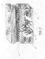
- FIG. 2is a schematic of the composite material of FIG. 1 with a metal body to be bonded to the matrix;
- FIG. 3is a schematic of the metal body of FIG. 2 being compressed to the matrix
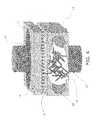
- FIG. 4is a schematic of a metal body being bonded to a non-metallic substrate via capacitor-discharge bonding
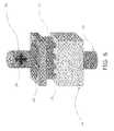
- FIG. 5is a schematic of a metal body being bonded to a non-metallic substrate via localized friction bonding
- FIG. 6is a schematic of a metal body being bonded to a non-metallic substrate via ultrasonic welding.
- FIG. 7is a schematic showing an enlarged view of the bond formed as the result of the method of the present invention between a metal surface and a substrate comprising microfilaments and/or nanofilaments.
- the present inventionprovides methods for cohesively bonding the surface of a metal body to a non-metallic substrate which may comprise contacting a metal surface of the metal body with a surface of the substrate.
- the substratemay comprise a plurality of microfilaments and/or nanofilaments which may provide microscopic asperities on the surface of the substrate in contact with the metal surface.
- the methodmay further use a variety of known joining process such as: friction welding, capacitor-discharge welding, ultrasonic welding and diffusion bonding to connect the filaments with the metallic body.
- These methodsmay comprise simultaneously applying normally-oriented pressure to the metal surface and laterally-oriented high frequency and low amplitude vibrations to the substrate and forming a cohesive bond between the metal surface and the substrate.
- the applied loadsare typically below those loads which would cause macro-deformation of the components' materials.
- This processknown as localized friction welding, creates localized increases of contact temperature that do not exceed 0.5-0.8 times the melting point temperature of such materials and the temperature of the materials can remain in this range for 0.004 seconds to over 3600 seconds depending upon the type of materials being bonded, the joint properties of these materials, and the heating method being used.
- joining processesmay comprise radiant heating, induction heating and direct or indirect resistance heating.
- the diffusion bonding processmay be further assisted by additionally exposing the components' materials to higher temperatures, inert gases and/or a vacuum.
- the cohesive bondmay be formed by diffusion of the microfilament and/or nanofilament material into the metal layer, thus forming a stronger bond than one without the presence of the microfilaments and/or nanofilaments.
- the substrate 14comprises a matrix that may include fibers 18 and a plurality of microfilaments and/or nanofilaments 16 randomly oriented and embedded within the matrix.
- the microfilaments and/or nanofilaments 16are metallic, but alternatively they may comprise ceramic, plastic, or any other material known to the skilled artisan. Some or all of the plurality of microfilaments and/or nanofilaments 16 may extend out of a surface 15 of the substrate 14 , whereas others may be embedded in the substrate without extending out of the substrate.
- substrate 14 of FIG. 1may be any material desired to form a bond to a metal surface 12 and which may have microfilaments and/or nanofilaments 16 dispersed therein.
- the substrate 14comprises non-metallic material.
- the substrate 14may comprise a composite material such as, but not limited to, a metal matrix composite, a ceramic composite or a polymer composite.
- the polymer compositemay comprise unidirectional or multidirectional oriented fibers of graphite, fiberglass, aramid or a combination thereof.
- Substrate 14may comprise any size or form desired. It may be preformed into a desired shape or part. Alternatively, it may be shaped or formed after bonding to the metal surface.
- the substrate 14may comprise a plurality of microfilaments and/or nanofilaments 16 .
- the plurality of microfilaments and/or nanofilaments 16may be dispersed on and below a surface 15 (see FIG. 1 ) of the substrate 14 .
- the plurality of microfilaments and/or nanofilaments 16are introduced individually into the substrate 14 and may create an intricate network in the substrate 14 .
- the plurality of microfilaments and/or nanofilaments 16may be introduced into the substrate 14 being physically connected to one another, forming a structure such as, but not limited to, a micrometric or nanometric sized foam. It will be appreciated that a network of microfilaments and/or nanofilaments 16 may provide firstly, a strong adhesion bond within the substrate 14 and subsequently provide the opportunity for bonding between metal surface 12 and substrate 14 .
- a metal-bonded substrateis shown in FIG. 2 .
- a metal body 12may be cohesively bonded to the substrate 14 via one of several bonding methods, three of which will be described below in further detail.
- the substrate 14 in FIG. 2may comprise a plurality of randomly-oriented microfilaments and/or nanofilaments 16 and a plurality of aligned fibers 18 dispersed throughout substrate 14 and which are usually introduced as a specially fabricated cloth.
- the microfilaments and/or nanofilaments 16may form microscopic asperities on the surface 15 of the substrate 14 and may change the material characteristics of the substrate 14 at or near the surface 15 .
- the plurality of microfilaments and/or nanofilaments 16may be dispersed in the substrate 14 during the manufacture of the substrate 14 . Alternately, the microfilaments and/or nanofilaments 16 may be dispersed in the substrate 14 afterwards by other methods known in the art.
- the plurality of microfilaments and/or nanofilaments 16may be distributed throughout the substrate 14 to provide the optimal cohesive bond between the substrate 14 and the surface of the metal body 12 .
- the plurality of microfilaments and/or nanofilaments 16may be evenly distributed throughout the substrate 14 or they may be concentrated at the surface 15 of the substrate 14 where the surface of the metal body 12 will be bonded, gradually decreasing in the substrate 14 away from the surface 15 .
- the microfilaments and/or nanofilaments 16may comprise a material capable of bonding with the metal body 12 .
- the microfilaments and/or nanofilaments 16may comprise a metal such as, but not limited to, stainless steel or a titanium alloy.
- the microfilaments and/or nanofilaments 16may comprise a material capable of sustaining the bond or joint between the substrate 14 and the metal body 12 and may also have desired corrosion resistance as well as little or no adherent oxide layer.
- those filaments 16may have a diameter of less than 100 nm up to 1000 nm in cross-sectional dimension.
- nanofilaments 16 produced using other, advanced technologiesmay be less than about 100 nm in cross-sectional dimension. It will be appreciated that the cross-sectional dimension of the nanofilaments 16 may be small enough to provide an optimal number of interactions with the metal body 12 but still retain integrity and strength. Based on the present technology the nanofilaments 16 may have a length less than about 400 ⁇ m.
- the nanofilaments 16may be made by processes known in the art such as, but not limited to, the process described in U.S. Pat. No. 6,444,256, which is herein incorporated by reference
- the surface of the metal body 12may be the surface of a metal strip, a metal sheet, a metal plate or a metal block. It is contemplated that any metal surface found on any part or material may be bonded to the substrate 14 using the process of the present application.
- the metal surface 12may comprise any metal having the desired properties for the application in which the bonded metal and composite complex 10 are to be used.
- the metal body surface 12may comprise stainless steel or titanium.
- a method for cohesive bonding a metal surface 12 to a substrate 14is provided.
- pressuremay be applied in a direction 11 against the metal body 12 such that the metal body 12 is compressed against the substrate 14 .
- the pressurecan be applied uniaxially or isostatically.
- Uniaxial pressuregenerally requires lower pressure in the range of 3-10 MPa to avoid macro-deformation of the bonded materials. Additionally, this process typically requires good surface finish on the mating surfaces as the contribution to bonding provided by plastic yielding is restricted. In general, surface finishes with roughness values better than 0.4 ⁇ m RA and which are free from contaminants are advantageous for bonding purposes.
- isostatic pressuremuch higher pressures such as 100-200 MPa may be possible and therefore surface finish is not as critical.
- FIG. 4An exemplary method for cohesive bonding is shown in FIG. 4 known as capacitor-discharge welding.
- a substrate 14is provided which includes fibers 18 and a plurality of microfilaments and/or nanofilaments 16 embedded in the substrate 14 .
- a metal body 12is brought into contact with a surface of the substrate 14 such that a portion of the plurality of microfilaments and/or nanofilaments 16 found on the surface 15 of substrate 14 may contact the metal body 12 .
- Capacitors(not shown) are provided to be coupled to at least one of the metal body 12 and substrate 14 through contact elements 25 .
- Contact elements 25may be placed onto at least one surface of the metal body 12 and/or substrate 14 .
- Energy stored in the capacitors at specific voltagesmay be released or discharged through contact elements 25 to 14 and 12 .
- an instantaneous arcmay be created which melts the adjoining surfaces of the metal body 12 and microfilaments and/or nanofilaments 16 .
- pressuremay be applied to both materials such that the materials compress against one another and a cohesive bond is formed between the metal body 12 and microfilaments and/or nanofilaments 16 , as the molten metal solidifies.
- the capacitor-discharge welding processis an extremely efficient method for welding a wide variety of metals including mild steel, stainless steel, aluminium, brass, copper, titanium, and other similar metals.
- a powerful bank of capacitorsmay be provided with each capacitor storing energy at a specific voltage.
- the capacitorsmay range between 450-3000 volts. The voltage may depend on the size and material of the component being formed.
- Large capacitor-discharge welding machinesmay output 400 KA of current and 50 kJ of energy. When energy is discharged, a cohesive bond may be formed in approximately 0.004 seconds or more.
- the capacitor-discharge welding processis advantageous for many reasons.
- the short welding timelocalizes the heat and creates welds adjacent to heat sensitive portions of the material.
- the capacitor-discharge welding processprovides excellent bonding with a variety of similar and dissimilar materials without requiring any water cooling, significant power requirements, nor substantial operating costs for high production rates. This process may be performed in most environments as it does not require large amounts of space and produces very little, if any, fumes or smoke.
- the methodmay comprise the step of contacting a metal body 12 with a surface 15 of a substrate 14 .
- the substrate 14may comprise a plurality of microfilaments and/or nanofilaments 16 dispersed into and below the surface 15 of the substrate 14 .
- the surface of the metal body 12may have microscopic asperities (not shown) as it will be appreciated most metal surfaces are not absolutely smooth.
- the microscopic asperities 17 of the surface of the metal body 12may come into contact with the microfilaments and/or nanofilaments 16 of the substrate 14 .
- the microfilaments and/or nanofilaments 16provide microscopic asperities that aid in the bonding process and may contact the microscopic asperities 17 of the metal body 12 .
- the methodmay also comprise the step of simultaneously applying normally-oriented pressure 20 on the metal body 12 and laterally-oriented high frequency and low amplitude vibration 22 to the substrate 14 as shown in FIG. 5 .
- the application of the combined pressure and vibrationmay produce high temperatures localized between the adjoining surface of the metal body 12 and the microfilaments and/or nanofilaments 16 and may further facilitate metal transfer between the metal body 12 and the material of the microfilaments and/or nanofilaments 16 that is exposed at the surface 15 of the substrate 14 . This metal transfer may result in a
- Friction bondinggenerally is a solid phase pressure welding process where little to no actual melting of the metal body occurs. By rubbing the adjoining surfaces of the metal body and the substrate together, sufficient heat is produced for creating local plastic zones. Accordingly, two atomically clean metal surfaces may be brought together under pressure and an inter-metallic bond is formed. The corresponding heat may be confined to the interface of the two materials. The heat input may be low and the amount of work applied to the bonded area results in grain refinement.
- friction bondingOne advantageous characteristic associated with friction bonding is the ability to weld alloys and combinations of alloys which were previously regarded as “un-weldable.” With localized friction bonding processes, it is now possible to produce dissimilar metal joints, join steel, copper, and aluminium to themselves and/or to each other, and to successfully weld alloys.
- the methodmay comprise the step of contacting a metal body 12 with a surface 15 of a substrate 14 .
- the substrate 14may comprise a plurality of microfilaments and/or nanofilaments 16 dispersed into and below the surface 15 of the substrate 14 .
- the surface of the metal body 12may have microscopic asperities as it will be appreciated most metal surfaces are not absolutely smooth.
- a sonotrode 26may be positioned to be in contact with a surface of the metal body 12 .
- an anvil 27may be positioned against a surface of the substrate 14 and it holds the materials to be welded statically together.
- a welding toolmay attach or couple to the material to be bonded and the tool moves in a longitudinal direction.
- the metal body 12 and substrate 14may be pressed together and a generator (not shown) may produce electrical oscillations of ultrasonic frequency.
- a transducer(not shown) may convert the electrical oscillations into mechanical vibration which in turn is transmitted to the sonotrode 26 .
- the sonotrodetransmits the ultrasonic vibrations 28 to the metal body 12 and substrate 14 .
- the sonotrode 26needs to be mounted tightly to the metal body 12 to avoid friction and other losses. The simultaneous action of static and dynamic forces causes the metal body 12 and substrate 14 to fuse together without requiring the addition of an extrinsic material.
- Vibrationsmay reach frequencies of about 20-70 kHz.
- a complex processis triggered involving static forces, oscillating shearing forces, and a moderate temperature increase in the welding area. The magnitude of these factors depends on the thickness of the work pieces (viz., the metal body 12 and substrate 14 ), their surface structure, and their mechanical properties. Typical frequencies may reach 20-40 kHz, which is above the frequency that is audible to a human ear and also permits the best possible use of energy.
- ultrasonic weldingis used for forming small components that require less energy such as watches, cassettes, plastic products, toys, medical tools, and packaging.
- a resulting component 24is formed from cohesive bonding between a metal body 12 and a substrate 14 .
- the metal body 12may include microscopic asperities and the substrate may include a plurality of microfilaments and/or nanofilaments 16 .
- Other componentsmay be formed via any of the above-described methods and the type of component being made should not be limiting.
Landscapes
- Engineering & Computer Science (AREA)
- Mechanical Engineering (AREA)
- Pressure Welding/Diffusion-Bonding (AREA)
Abstract
Description
Claims (11)
Priority Applications (2)
| Application Number | Priority Date | Filing Date | Title |
|---|---|---|---|
| US12/045,347US8186566B2 (en) | 2007-03-10 | 2008-03-10 | Method for cohesively bonding metal to a non-metallic substrate |
| US13/462,926US8397976B2 (en) | 2007-03-10 | 2012-05-03 | Method for cohesively bonding metal to a non-metallic substrate using capacitors |
Applications Claiming Priority (2)
| Application Number | Priority Date | Filing Date | Title |
|---|---|---|---|
| US89421307P | 2007-03-10 | 2007-03-10 | |
| US12/045,347US8186566B2 (en) | 2007-03-10 | 2008-03-10 | Method for cohesively bonding metal to a non-metallic substrate |
Related Child Applications (1)
| Application Number | Title | Priority Date | Filing Date |
|---|---|---|---|
| US13/462,926DivisionUS8397976B2 (en) | 2007-03-10 | 2012-05-03 | Method for cohesively bonding metal to a non-metallic substrate using capacitors |
Publications (2)
| Publication Number | Publication Date |
|---|---|
| US20080217379A1 US20080217379A1 (en) | 2008-09-11 |
| US8186566B2true US8186566B2 (en) | 2012-05-29 |
Family
ID=39740631
Family Applications (2)
| Application Number | Title | Priority Date | Filing Date |
|---|---|---|---|
| US12/045,347Expired - Fee RelatedUS8186566B2 (en) | 2007-03-10 | 2008-03-10 | Method for cohesively bonding metal to a non-metallic substrate |
| US13/462,926Expired - Fee RelatedUS8397976B2 (en) | 2007-03-10 | 2012-05-03 | Method for cohesively bonding metal to a non-metallic substrate using capacitors |
Family Applications After (1)
| Application Number | Title | Priority Date | Filing Date |
|---|---|---|---|
| US13/462,926Expired - Fee RelatedUS8397976B2 (en) | 2007-03-10 | 2012-05-03 | Method for cohesively bonding metal to a non-metallic substrate using capacitors |
Country Status (1)
| Country | Link |
|---|---|
| US (2) | US8186566B2 (en) |
Cited By (6)
| Publication number | Priority date | Publication date | Assignee | Title |
|---|---|---|---|---|
| US9115264B2 (en) | 2010-02-15 | 2015-08-25 | Productive Research Llc | Delamination resistant, weldable and formable light weight composites |
| US9233526B2 (en) | 2012-08-03 | 2016-01-12 | Productive Research Llc | Composites having improved interlayer adhesion and methods thereof |
| US9239068B2 (en) | 2009-12-28 | 2016-01-19 | Productive Research Llc | Processes for welding composite materials and articles therefrom |
| US9434134B2 (en) | 2008-08-18 | 2016-09-06 | Productive Research Llc | Formable light weight composites |
| US11046015B2 (en) | 2017-05-31 | 2021-06-29 | Yibo Su | System and apparatus for fiber reinforced thermoplastics joiner |
| US11338552B2 (en) | 2019-02-15 | 2022-05-24 | Productive Research Llc | Composite materials, vehicle applications and methods thereof |
Families Citing this family (5)
| Publication number | Priority date | Publication date | Assignee | Title |
|---|---|---|---|---|
| JP5886319B2 (en) | 2011-01-04 | 2016-03-16 | テイジン・アラミド・ビー.ブイ. | Paper containing microfilament |
| US9889633B2 (en) | 2014-04-10 | 2018-02-13 | Honda Motor Co., Ltd. | Attachment method for laminate structures |
| JP2016034656A (en)* | 2014-08-01 | 2016-03-17 | 株式会社アドウェルズ | Face joining method |
| US11298775B2 (en) | 2018-05-24 | 2022-04-12 | Honda Motor Co., Ltd. | Continuous ultrasonic additive manufacturing |
| CN110524891A (en)* | 2018-05-24 | 2019-12-03 | 本田技研工业株式会社 | Continuous ultrasonic increasing material manufacturing |
Citations (25)
| Publication number | Priority date | Publication date | Assignee | Title |
|---|---|---|---|---|
| US3541671A (en)* | 1967-06-09 | 1970-11-24 | Int Standard Electric Corp | Process of fixing paper to metal |
| US4144110A (en)* | 1969-06-05 | 1979-03-13 | Jane Luc | Dynamic friction bonding process |
| US4330704A (en)* | 1980-08-08 | 1982-05-18 | Raychem Corporation | Electrical devices comprising conductive polymers |
| US4639388A (en) | 1985-02-12 | 1987-01-27 | Chromalloy American Corporation | Ceramic-metal composites |
| US4844323A (en) | 1987-02-26 | 1989-07-04 | Nihon Sinku Gijutsu Kabusiki Kaisha | Method for joining ceramics |
| US5153057A (en)* | 1989-02-15 | 1992-10-06 | Technical Ceramics Laboratories, Inc. | Shaped bodies containing short inorganic fibers or whiskers within a metal matrix |
| JPH06277854A (en)* | 1993-02-24 | 1994-10-04 | Mitsubishi Heavy Ind Ltd | Method for joining short fiber reinforced metallic materials |
| US5697545A (en)* | 1994-07-15 | 1997-12-16 | British Nuclear Fuels Plc | Method of friction welding |
| US6187260B1 (en)* | 1996-12-09 | 2001-02-13 | The Chinese University Of Hong Kong | Aluminum metal matrix composite materials reinforced by intermetallic compounds and alumina whiskers |
| US6450393B1 (en)* | 1998-06-30 | 2002-09-17 | Trustees Of Tufts College | Multiple-material prototyping by ultrasonic adhesion |
| US6457629B1 (en) | 1999-10-04 | 2002-10-01 | Solidica, Inc. | Object consolidation employing friction joining |
| US6645610B1 (en)* | 1998-04-20 | 2003-11-11 | Northrop Grumann | Cured composite material formed utilizing Z-peel sheets |
| US6652958B2 (en)* | 2000-10-19 | 2003-11-25 | Polymatech Co., Ltd. | Thermally conductive polymer sheet |
| US6814823B1 (en)* | 1999-09-16 | 2004-11-09 | Solidica, Inc. | Object consolidation through sequential material deposition |
| US7090113B2 (en)* | 2002-04-08 | 2006-08-15 | General Electric Company | Inertia welded shaft and method therefor |
| US7334997B2 (en)* | 2005-09-16 | 2008-02-26 | General Electric Company | Hybrid blisk |
| US7374474B2 (en)* | 2001-10-09 | 2008-05-20 | Hitachi Chemical Co., Ltd. | Polishing pad for CMP, method for polishing substrate using it and method for producing polishing pad for CMP |
| US7431980B2 (en)* | 2004-11-08 | 2008-10-07 | Azdel, Inc. | Composite thermoplastic sheets including natural fibers |
| US7459044B2 (en)* | 2002-08-26 | 2008-12-02 | E. I. Du Pont De Nemours And Company | Sheet material especially useful for circuit boards |
| US7507310B2 (en)* | 2006-12-29 | 2009-03-24 | General Electric Company | Friction stir welding of fiber reinforced thermoplastics |
| US20100239428A1 (en)* | 2006-11-08 | 2010-09-23 | General Electric Company | System for manufacturing a rotor having an mmc ring component and a unitary airfoil component |
| US7823763B2 (en)* | 2007-08-01 | 2010-11-02 | Gm Global Technology Operations, Inc. | Friction welding method and products made using the same |
| US7927708B2 (en)* | 2008-08-18 | 2011-04-19 | Productive Research Llc | Formable light weight composites |
| US7959058B1 (en)* | 2005-01-13 | 2011-06-14 | The United States Of America As Represented By The Secretary Of The Navy | Hybrid composite welded joint |
| US20110200816A1 (en)* | 2010-02-15 | 2011-08-18 | Productive Research Llc | Formable light weight composite material systems and methods |
Family Cites Families (5)
| Publication number | Priority date | Publication date | Assignee | Title |
|---|---|---|---|---|
| US2077600A (en)* | 1936-09-03 | 1937-04-20 | Glenn W Watson | Welding by the charge of a condenser |
| US5079070A (en)* | 1990-10-11 | 1992-01-07 | International Business Machines Corporation | Repair of open defects in thin film conductors |
| FR2792394B1 (en)* | 1999-04-16 | 2001-07-27 | Gaz De France | METHOD FOR REALIZING A FLAME HANGING SURFACE |
| KR100451411B1 (en)* | 2002-06-03 | 2004-10-06 | 국방과학연구소 | Micro-welder |
| US6945448B2 (en)* | 2002-06-18 | 2005-09-20 | Zimmer Technology, Inc. | Method for attaching a porous metal layer to a metal substrate |
- 2008
- 2008-03-10USUS12/045,347patent/US8186566B2/ennot_activeExpired - Fee Related
- 2012
- 2012-05-03USUS13/462,926patent/US8397976B2/ennot_activeExpired - Fee Related
Patent Citations (25)
| Publication number | Priority date | Publication date | Assignee | Title |
|---|---|---|---|---|
| US3541671A (en)* | 1967-06-09 | 1970-11-24 | Int Standard Electric Corp | Process of fixing paper to metal |
| US4144110A (en)* | 1969-06-05 | 1979-03-13 | Jane Luc | Dynamic friction bonding process |
| US4330704A (en)* | 1980-08-08 | 1982-05-18 | Raychem Corporation | Electrical devices comprising conductive polymers |
| US4639388A (en) | 1985-02-12 | 1987-01-27 | Chromalloy American Corporation | Ceramic-metal composites |
| US4844323A (en) | 1987-02-26 | 1989-07-04 | Nihon Sinku Gijutsu Kabusiki Kaisha | Method for joining ceramics |
| US5153057A (en)* | 1989-02-15 | 1992-10-06 | Technical Ceramics Laboratories, Inc. | Shaped bodies containing short inorganic fibers or whiskers within a metal matrix |
| JPH06277854A (en)* | 1993-02-24 | 1994-10-04 | Mitsubishi Heavy Ind Ltd | Method for joining short fiber reinforced metallic materials |
| US5697545A (en)* | 1994-07-15 | 1997-12-16 | British Nuclear Fuels Plc | Method of friction welding |
| US6187260B1 (en)* | 1996-12-09 | 2001-02-13 | The Chinese University Of Hong Kong | Aluminum metal matrix composite materials reinforced by intermetallic compounds and alumina whiskers |
| US6645610B1 (en)* | 1998-04-20 | 2003-11-11 | Northrop Grumann | Cured composite material formed utilizing Z-peel sheets |
| US6450393B1 (en)* | 1998-06-30 | 2002-09-17 | Trustees Of Tufts College | Multiple-material prototyping by ultrasonic adhesion |
| US6814823B1 (en)* | 1999-09-16 | 2004-11-09 | Solidica, Inc. | Object consolidation through sequential material deposition |
| US6457629B1 (en) | 1999-10-04 | 2002-10-01 | Solidica, Inc. | Object consolidation employing friction joining |
| US6652958B2 (en)* | 2000-10-19 | 2003-11-25 | Polymatech Co., Ltd. | Thermally conductive polymer sheet |
| US7374474B2 (en)* | 2001-10-09 | 2008-05-20 | Hitachi Chemical Co., Ltd. | Polishing pad for CMP, method for polishing substrate using it and method for producing polishing pad for CMP |
| US7090113B2 (en)* | 2002-04-08 | 2006-08-15 | General Electric Company | Inertia welded shaft and method therefor |
| US7459044B2 (en)* | 2002-08-26 | 2008-12-02 | E. I. Du Pont De Nemours And Company | Sheet material especially useful for circuit boards |
| US7431980B2 (en)* | 2004-11-08 | 2008-10-07 | Azdel, Inc. | Composite thermoplastic sheets including natural fibers |
| US7959058B1 (en)* | 2005-01-13 | 2011-06-14 | The United States Of America As Represented By The Secretary Of The Navy | Hybrid composite welded joint |
| US7334997B2 (en)* | 2005-09-16 | 2008-02-26 | General Electric Company | Hybrid blisk |
| US20100239428A1 (en)* | 2006-11-08 | 2010-09-23 | General Electric Company | System for manufacturing a rotor having an mmc ring component and a unitary airfoil component |
| US7507310B2 (en)* | 2006-12-29 | 2009-03-24 | General Electric Company | Friction stir welding of fiber reinforced thermoplastics |
| US7823763B2 (en)* | 2007-08-01 | 2010-11-02 | Gm Global Technology Operations, Inc. | Friction welding method and products made using the same |
| US7927708B2 (en)* | 2008-08-18 | 2011-04-19 | Productive Research Llc | Formable light weight composites |
| US20110200816A1 (en)* | 2010-02-15 | 2011-08-18 | Productive Research Llc | Formable light weight composite material systems and methods |
Cited By (14)
| Publication number | Priority date | Publication date | Assignee | Title |
|---|---|---|---|---|
| US9434134B2 (en) | 2008-08-18 | 2016-09-06 | Productive Research Llc | Formable light weight composites |
| US9889634B2 (en) | 2008-08-18 | 2018-02-13 | Productive Research Llc | Formable light weight composites |
| US9239068B2 (en) | 2009-12-28 | 2016-01-19 | Productive Research Llc | Processes for welding composite materials and articles therefrom |
| US9415568B2 (en) | 2010-02-15 | 2016-08-16 | Productive Research Llc | Formable light weight composite material systems and methods |
| US9115264B2 (en) | 2010-02-15 | 2015-08-25 | Productive Research Llc | Delamination resistant, weldable and formable light weight composites |
| US9849651B2 (en) | 2010-02-15 | 2017-12-26 | Productive Research Llc | Formable light weight composite material systems and methods |
| US9981451B2 (en) | 2010-02-15 | 2018-05-29 | Productive Research Llc | Delamination resistant, weldable and formable light weight composites |
| US10457019B2 (en) | 2010-02-15 | 2019-10-29 | Productive Research Llc | Light weight composite material systems, polymeric materials, and methods |
| US10710338B2 (en) | 2010-02-15 | 2020-07-14 | Productive Research Llc | Delamination resistant, weldable and formable light weight composites |
| US11084253B2 (en) | 2010-02-15 | 2021-08-10 | Productive Research Llc | Light weight composite material systems, polymeric materials, and methods |
| US11331880B2 (en) | 2010-02-15 | 2022-05-17 | Productive Research Llc | Delamination resistant, weldable and formable light weight composites |
| US9233526B2 (en) | 2012-08-03 | 2016-01-12 | Productive Research Llc | Composites having improved interlayer adhesion and methods thereof |
| US11046015B2 (en) | 2017-05-31 | 2021-06-29 | Yibo Su | System and apparatus for fiber reinforced thermoplastics joiner |
| US11338552B2 (en) | 2019-02-15 | 2022-05-24 | Productive Research Llc | Composite materials, vehicle applications and methods thereof |
Also Published As
| Publication number | Publication date |
|---|---|
| US20080217379A1 (en) | 2008-09-11 |
| US20120273125A1 (en) | 2012-11-01 |
| US8397976B2 (en) | 2013-03-19 |
Similar Documents
| Publication | Publication Date | Title |
|---|---|---|
| US8186566B2 (en) | Method for cohesively bonding metal to a non-metallic substrate | |
| JP5376391B2 (en) | Dissimilar metal joining method and joining structure | |
| US5397408A (en) | Ultrasonic welding of metallized plastic | |
| JP2015509850A (en) | Method of welding parts using low thermal conductivity tool and vibration welder with high mechanical properties and corresponding vibration welder | |
| CN103521937A (en) | Joining of two parts by means of a combination of electrical resistance welding and friction welding | |
| CA2924209A1 (en) | Method for connecting a surface-structured workpiece and a plastic workpiece | |
| JPS5948714B2 (en) | Method of pressure welding metal base materials using eutectic reaction | |
| US20080041922A1 (en) | Hybrid Resistance/Ultrasonic Welding System and Method | |
| US5270135A (en) | Articles including a ceramic member and a metal member bonded together | |
| JP2014166646A (en) | Solid-phase welding method for metal workpiece | |
| JPH0232077B2 (en) | ||
| JP5597946B2 (en) | Low-temperature metal joining method | |
| JPS6311118B2 (en) | ||
| US20210129207A1 (en) | Ultrasonic Rivet Joining of Dissimilar Materials | |
| CN109570745B (en) | A method for ultrasonic-assisted self-propagating connection of metal and non-metal | |
| JP2004243402A (en) | Metal foil joining method, and metal foil connecting device | |
| JP2002096180A (en) | Ultrasonic welding machine | |
| Acharya et al. | Application of ultrasonic welding for dissimilar metals: a review | |
| Thapliyal | Ultrasonic welding—a modern welding technology for metals and plastics | |
| JP2022182843A (en) | LAMINATED PRODUCT AND METHOD FOR MANUFACTURING LAMINATED BODY | |
| JP6690619B2 (en) | Metal-resin bonded body and method for manufacturing the same | |
| JP2018079472A (en) | Solid phase bonding method of aluminum base metal and metal base metal | |
| JP4064111B2 (en) | Ultrasonic pressure welding method | |
| JP7156009B2 (en) | Manufacturing method of composite of coated metal material and resin material | |
| JP4180405B2 (en) | Ultrasonic pressure welding method |
Legal Events
| Date | Code | Title | Description |
|---|---|---|---|
| AS | Assignment | Owner name:NEXGENEERING TECHNOLOGY LLC, INDIANA Free format text:ASSIGNMENT OF ASSIGNORS INTEREST;ASSIGNORS:SILVIAN, LUCIAN M;GEVERS, DAVID E;ABRAMOVICI, EUGEN;REEL/FRAME:020975/0352;SIGNING DATES FROM 20080429 TO 20080505 Owner name:NEXGENEERING TECHNOLOGY LLC, INDIANA Free format text:ASSIGNMENT OF ASSIGNORS INTEREST;ASSIGNORS:SILVIAN, LUCIAN M;GEVERS, DAVID E;ABRAMOVICI, EUGEN;SIGNING DATES FROM 20080429 TO 20080505;REEL/FRAME:020975/0352 | |
| STCF | Information on status: patent grant | Free format text:PATENTED CASE | |
| CC | Certificate of correction | ||
| FPAY | Fee payment | Year of fee payment:4 | |
| AS | Assignment | Owner name:SILVIAN, LUCIAN M., INDIANA Free format text:ASSIGNMENT OF ASSIGNORS INTEREST;ASSIGNOR:NEXGENEERING TECHNOLOGY LLC;REEL/FRAME:037577/0677 Effective date:20160112 Owner name:ABRAMOVICI, EUGEN, CANADA Free format text:ASSIGNMENT OF ASSIGNORS INTEREST;ASSIGNOR:NEXGENEERING TECHNOLOGY LLC;REEL/FRAME:037577/0677 Effective date:20160112 Owner name:GEVERS, DAVID E., INDIANA Free format text:ASSIGNMENT OF ASSIGNORS INTEREST;ASSIGNOR:NEXGENEERING TECHNOLOGY LLC;REEL/FRAME:037577/0677 Effective date:20160112 | |
| FEPP | Fee payment procedure | Free format text:MAINTENANCE FEE REMINDER MAILED (ORIGINAL EVENT CODE: REM.); ENTITY STATUS OF PATENT OWNER: SMALL ENTITY | |
| LAPS | Lapse for failure to pay maintenance fees | Free format text:PATENT EXPIRED FOR FAILURE TO PAY MAINTENANCE FEES (ORIGINAL EVENT CODE: EXP.); ENTITY STATUS OF PATENT OWNER: SMALL ENTITY | |
| STCH | Information on status: patent discontinuation | Free format text:PATENT EXPIRED DUE TO NONPAYMENT OF MAINTENANCE FEES UNDER 37 CFR 1.362 |