US8186517B2 - Strainer housing assembly and stand for pump - Google Patents
Strainer housing assembly and stand for pumpDownload PDFInfo
- Publication number
- US8186517B2 US8186517B2US12/270,349US27034908AUS8186517B2US 8186517 B2US8186517 B2US 8186517B2US 27034908 AUS27034908 AUS 27034908AUS 8186517 B2US8186517 B2US 8186517B2
- Authority
- US
- United States
- Prior art keywords
- housing
- strainer
- respect
- cover
- strainer housing
- Prior art date
- Legal status (The legal status is an assumption and is not a legal conclusion. Google has not performed a legal analysis and makes no representation as to the accuracy of the status listed.)
- Active, expires
Links
Images


Classifications
- B—PERFORMING OPERATIONS; TRANSPORTING
- B01—PHYSICAL OR CHEMICAL PROCESSES OR APPARATUS IN GENERAL
- B01D—SEPARATION
- B01D35/00—Filtering devices having features not specifically covered by groups B01D24/00 - B01D33/00, or for applications not specifically covered by groups B01D24/00 - B01D33/00; Auxiliary devices for filtration; Filter housing constructions
- B01D35/26—Filters with built-in pumps filters provided with a pump mounted in or on the casing
- B—PERFORMING OPERATIONS; TRANSPORTING
- B01—PHYSICAL OR CHEMICAL PROCESSES OR APPARATUS IN GENERAL
- B01D—SEPARATION
- B01D29/00—Filters with filtering elements stationary during filtration, e.g. pressure or suction filters, not covered by groups B01D24/00 - B01D27/00; Filtering elements therefor
- B01D29/11—Filters with filtering elements stationary during filtration, e.g. pressure or suction filters, not covered by groups B01D24/00 - B01D27/00; Filtering elements therefor with bag, cage, hose, tube, sleeve or like filtering elements
- B01D29/31—Self-supporting filtering elements
- B01D29/35—Self-supporting filtering elements arranged for outward flow filtration
- F—MECHANICAL ENGINEERING; LIGHTING; HEATING; WEAPONS; BLASTING
- F04—POSITIVE - DISPLACEMENT MACHINES FOR LIQUIDS; PUMPS FOR LIQUIDS OR ELASTIC FLUIDS
- F04D—NON-POSITIVE-DISPLACEMENT PUMPS
- F04D29/00—Details, component parts, or accessories
- F04D29/40—Casings; Connections of working fluid
- F04D29/42—Casings; Connections of working fluid for radial or helico-centrifugal pumps
- F04D29/426—Casings; Connections of working fluid for radial or helico-centrifugal pumps especially adapted for liquid pumps
- F—MECHANICAL ENGINEERING; LIGHTING; HEATING; WEAPONS; BLASTING
- F04—POSITIVE - DISPLACEMENT MACHINES FOR LIQUIDS; PUMPS FOR LIQUIDS OR ELASTIC FLUIDS
- F04D—NON-POSITIVE-DISPLACEMENT PUMPS
- F04D29/00—Details, component parts, or accessories
- F04D29/60—Mounting; Assembling; Disassembling
- F04D29/605—Mounting; Assembling; Disassembling specially adapted for liquid pumps
- F—MECHANICAL ENGINEERING; LIGHTING; HEATING; WEAPONS; BLASTING
- F04—POSITIVE - DISPLACEMENT MACHINES FOR LIQUIDS; PUMPS FOR LIQUIDS OR ELASTIC FLUIDS
- F04D—NON-POSITIVE-DISPLACEMENT PUMPS
- F04D29/00—Details, component parts, or accessories
- F04D29/60—Mounting; Assembling; Disassembling
- F04D29/62—Mounting; Assembling; Disassembling of radial or helico-centrifugal pumps
- F04D29/628—Mounting; Assembling; Disassembling of radial or helico-centrifugal pumps especially adapted for liquid pumps
- F—MECHANICAL ENGINEERING; LIGHTING; HEATING; WEAPONS; BLASTING
- F04—POSITIVE - DISPLACEMENT MACHINES FOR LIQUIDS; PUMPS FOR LIQUIDS OR ELASTIC FLUIDS
- F04D—NON-POSITIVE-DISPLACEMENT PUMPS
- F04D29/00—Details, component parts, or accessories
- F04D29/70—Suction grids; Strainers; Dust separation; Cleaning
- F04D29/708—Suction grids; Strainers; Dust separation; Cleaning specially for liquid pumps
- B—PERFORMING OPERATIONS; TRANSPORTING
- B01—PHYSICAL OR CHEMICAL PROCESSES OR APPARATUS IN GENERAL
- B01D—SEPARATION
- B01D2201/00—Details relating to filtering apparatus
- B01D2201/40—Special measures for connecting different parts of the filter
- B01D2201/4084—Snap or Seeger ring connecting means
- Y—GENERAL TAGGING OF NEW TECHNOLOGICAL DEVELOPMENTS; GENERAL TAGGING OF CROSS-SECTIONAL TECHNOLOGIES SPANNING OVER SEVERAL SECTIONS OF THE IPC; TECHNICAL SUBJECTS COVERED BY FORMER USPC CROSS-REFERENCE ART COLLECTIONS [XRACs] AND DIGESTS
- Y10—TECHNICAL SUBJECTS COVERED BY FORMER USPC
- Y10T—TECHNICAL SUBJECTS COVERED BY FORMER US CLASSIFICATION
- Y10T137/00—Fluid handling
- Y10T137/794—With means for separating solid material from the fluid
- Y10T137/8122—Planar strainer normal to flow path
Definitions
- the present disclosurerelates to pumps and, more particularly, to pumps for use in connection with fluid circulation systems for swimming pools, spas, whirlpools and other recreational bodies of water.
- Numerous pumpshave been developed for use in connection with fluid circulation systems, e.g., for swimming pools, spas, whirlpools and the like. Since a pump is the heart of a fluid circulation system, it should function optimally at all times so as to provide users with the maximum amount of use and enjoyment of the associated swimming pool, spa, etc. Consequently, any required replacement, repair or maintenance of the pump and its associated components must be conducted quickly and efficiently in order to reduce any downtime of the system, as well as to reduce any associated labor costs. Because various components of conventional pumps are assembled by threads, bolts or the like, assembly and disassembly of such pumps are often time-consuming, inefficient and costly.
- Fluid-sealing couplingsadapted to retain fluid under pressure during equipment operation. Such couplings are also often designed to facilitate disassembly and reassembly of the equipment (e.g., to inspect and replace internal equipment components when the equipment is not in operation). In many instances, properly assembled couplings apply a predetermined level of compression on a sealing element (e.g., a washer or gasket) to prevent fluid from leaking out of the coupling.
- a sealing elemente.g., a washer or gasket
- the couplingmay be reassembled with improper alignment.
- the application of insufficient torque on one or more coupling bolts, relative to a predetermined levelmay result in fluid leakage at the coupling junction.
- the application of too much torque on one or more housing bolts, relative to a predetermined levelmay result in damage to the coupling seal (e.g., a crushed or crimped gasket/washer).
- Conventional pumpsare typically supported by a base that maintains the pump upright during operation.
- the basemay also function to elevate the pump and its associated components above a potential water level.
- the baseincludes a rearwardly extending, detachable support member that is adapted to prevent undesirable movement and provide a level of stability to the pump.
- many pumpsutilize and/or are provided with an inadequate support member, particularly when relatively violent movement/vibration is encountered.
- the connection(s) between a support member and the base/underside of a conventional pumpis not effective to impart desired stability during pump operation.
- a needalso exists for pump designs that provide an effective and reliable seal, while providing periodic access to the internal components associated therewith.
- pump assembliesthat include and/or are adapted to interact with base units that stabilize and support the pump in an effective manner.
- the pumpincludes a strainer housing that defines a cavity or internal region for receiving a strainer, and a strainer housing cover that is adapted to be removably mounted with respect to the strainer housing.
- the strainer housing coveris configured and dimensioned to form a seal with respect to the strainer housing.
- a top portion of the strainer housinggenerally defines an opening that is adapted to allow access to the cavity defined therewithin, e.g., to introduce and/or access a strainer basket positioned in the strainer housing.
- An outer, peripheral surface of the strainer housingis adapted to cooperate with the strainer housing cover. More particularly, a plurality of cam members are integrally formed with respect to the outer peripheral surface of the strainer housing, e.g., radially outward of the opening defined in the top portion of the strainer housing. The cam members are adapted to align and interact with cooperating cam members formed along an inner surface of the strainer housing cover.
- the strainer housing covergenerally includes or defines at least a pair of diametrically opposed handles extending radially outwardly with respect to the cover. The handles facilitate imparting rotational movement to the strainer housing cover relative to the strainer housing, e.g., to assemble or disassemble the cover relative to the housing.
- the pumpmay also include additional structures, features and/or functions that facilitate the design and/or operation thereof.
- the pumpgenerally includes an inlet formed on a front side of the strainer housing that is adapted to allow fluid to enter the strainer housing.
- An impeller housingcooperates with the strainer housing and generally defines an outlet on a top side or surface thereof.
- the impeller housingis integrally formed with respect to the strainer housing and is adapted to receive and encase a rotationally mounted impeller.
- An impeller coveris typically removably mounted with respect to the impeller housing.
- the impeller covergenerally includes a base portion that extends downwardly and is adapted to abut against a corresponding base portion of the impeller housing.
- the outer surface of the top portion of the strainer housingincludes three (3) cam members that are integrally formed with respect to the outer surface thereof.
- the cam membersare substantially elongated circumferentially with respect to the outer surface and positioned substantially equidistant from one another around the circumference of the strainer housing.
- the strainer housing coverincludes three cooperating cam members that correspond and are aligned with the foregoing strainer housing cam members.
- the cam members formed with respect to the outer surface of the strainer housinggenerally protrude radially outwardly with respect to the outer surface of the strainer housing, and the cooperating cam members formed with respect to the inner surface of the strainer housing cover extend radially inwardly with respect thereto.
- the respective cam membersare ramped to facilitate camming interaction therebetween.
- the interacting cam membersare thus configured and dimensioned to allow the strainer housing cover to be mounted with respect to the strainer housing and form a seal therewith when the cover is rotated into a closed position.
- An exemplary strainer housing coverincludes a lid element that is fabricated, in whole or in part, from a substantially transparent or opaque material, thereby permitting visualization of the interior region therebelow.
- the strainer housing covermay include an outer frame that includes the camming members and diametrically opposed handles, and that defines an interior opening.
- a transparent/translucent lidis configured and dimensioned to be mounted with respect to the frame, e.g., through notches formed in the interior opening that cooperate with extension lips formed on the lid.
- the lidmay define a circumferential flange-like portion that is adapted to engage/abut the underside of the frame and seal thereagainst when the lid/frame are mounted with respect to each other.
- the flange-like portionalso advantageously defines a substantially U-shaped undersurface that is adapted to receive a circumferential rim associated with the strainer housing, thereby facilitating sealing interaction therebetween.
- the outer surface of the strainer housingfurther includes a positioning tab or protuberance that is integrally formed with respect thereto.
- the positioning tabcorresponds to and is adapted to align with a positioning notch formed with respect to the inner surface of the strainer housing cover.
- the positioning notchis generally defined in one of the cam members formed on the cover, e.g., at a midpoint thereof.
- the positioning tabprotrudes radially outward and cooperates with the positioning notch of the strainer housing cover, whereby only one aligned orientation is accommodated when mounting the strainer housing cover with respect to the strainer housing.
- the positioning tabBy locating the positioning tab at or near a midpoint between cam members formed on the strainer housing, alignment of the strainer housing and cover is facilitated.
- the proper orientation for mounting the strainer housing cover with respect to the strainer housingis such that the diametrically opposed handles associated with the strainer housing cover are perpendicularly positioned with respect to the pump's central axis when the cover is rotated into its final, sealed position.
- the pump axisis parallel to the impeller shaft.
- the positioning notch/tabare positioned such that the diametrically opposed handles are initially angled relative to the pump's central axis, e.g., aligned at an angle of about 10°-20° relative to such central axis.
- the strainer housing and the impeller housinggenerally cooperate such that the strainer housing extends substantially vertically and the impeller housing extends substantially horizontally.
- a flow pathis defined internally with respect to the strainer housing and the impeller housing.
- the flow pathis adapted to allow fluid communication between the strainer housing and the impeller housing.
- Exemplary strainers for introduction into the strainer housingdefine a plurality of holes of a predetermined average dimension.
- the plurality of holesare generally deployed in a substantially mesh configuration.
- the straineris adapted to allow fluid to pass through the strainer housing, while preventing items that exceed the predetermined average dimension of the plurality of holes from passing through to the impeller housing.
- the strainerdefines an inlet opening formed on a front side thereof.
- the strainer's inlet openingis adapted to cooperate with the inlet formed on the strainer housing.
- the strainerincludes a ridge and an alignment fin that cooperates with a pair of alignment features defined on the inner surface of the strainer housing. The ridge and alignment fin are adapted to properly position the strainer within the strainer housing.
- the strainer coveris brought into engagement with the strainer housing by aligning the positioning tab with the corresponding positioning notch and bringing the U-shaped underside of the cover lid into engagement with the circumferential rim of the strainer housing.
- a positive pressure within the strainer housingwould cause the cover to disengage from the strainer housing, i.e., a seal is not yet formed therebetween.
- the userrotates the cover relative to the strainer housing, generally clockwise, such that the cooperating camming members are brought into engagement. The cooperative ramping of such camming members brings the cover into tight engagement with the strainer housing.
- Rotational motion of the cover relative to the strainer housingis generally limited by tolerancing between the camming members and an outwardly directed ridge member formed on the strainer housing.
- the camming membersbring the cover into an interference engagement with such outwardly directed ridge member, thereby preventing further rotational motion of the cover and effecting sealing engagement between the cover and the strainer housing.
- the sealis effected between the U-shaped underside of the lid and a corresponding rim of the strainer housing, which are firmly secured relative to each other through the camming structures described herein.
- the inclusion of three camming members, as described hereinsubstantially improves the sealing effect described herein, as sealing forces are well distributed and balanced during pump operation.
- a pumpin a further exemplary embodiment of the present disclosure, includes a stand that is adapted to: (i) be removably mounted with respect to base portions of the impeller housing and the impeller cover; and (ii) support the motor that drives the impeller.
- the standtypically includes a flange portion adapted to abut against the base portion of the impeller cover.
- the flange portiondefines at least one receiving chamber adapted to receive at least one base securing feature for removably mounting the stand with respect to the base portion of the impeller cover.
- the at least one base securing featurepasses through the base portions of the impeller housing and the impeller cover, and engages the at least one receiving chamber defined with respect to the motor stand.
- the standadvantageously provides structural support and imparts stability to the complete pump assembly.
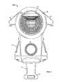
- FIG. 1is a perspective, partially exploded view of an exemplary pool pump associated with the present disclosure
- FIG. 2is a perspective, partially exploded view of an exemplary pool pump associated with the present disclosure, including a positioning tab/notch;
- FIG. 3is top side view of an exemplary pool pump associated with the present disclosure with the cover removed;
- FIG. 4is a top side view as shown in FIG. 3 with the cover mounted with respect to the strainer housing in a closed and substantially sealed position;
- FIG. 5is a perspective, partially exploded bottom side view of an exemplary pool pump associated with the present disclosure, including an exemplary strainer;
- FIG. 6is a side view of an exemplary strainer associated with the present disclosure.
- Typical pumps/pump assembliesinclude a strainer housing for receiving a strainer, and a removable strainer housing cover that is adapted to cooperate and to form a seal therewith.
- Advantageous cover/strainer housing subassembliesare provided that effectively and reliably interact and sealingly engage, while permitting ready access to the cavity defined within the strainer housing, e.g., to introduce and/or access a strainer basket positioned therewithin.
- FIG. 1provides a perspective view of an exemplary pool pump 10 according to the present disclosure.
- Pool pump 10includes a strainer housing 12 integrally formed with impeller housing 14 .
- strainer housing 12 and impeller housing 14define a substantially perpendicular relationship relative to each other, with strainer housing 12 extending substantially upwardly (vertically) with respect to base 15 , and impeller housing 14 extending substantially rearwardly (horizontally) with respect to strainer housing 12 .
- Impeller housing 14thus defines a central axis that is substantially horizontal based on the orientation of pool pump 10 in FIG. 1 and aligns with the impeller shaft (not pictured) that extends therethrough.
- Strainer housing 12defines a cavity 13 that is adapted to receive a strainer unit (shown in FIGS. 4-6 ; also referred to as a strainer). The strainer/strainer unit is discussed in greater detail below.
- strainer housing 12includes a top portion 22 that defines an opening to access cavity 13 .
- Top portion 22also defines a substantially circular geometry and includes an outer surface 23 .
- An outwardly extending ridge member 71is molded onto the outer surface of strainer housing 12 and extends around the circumference thereof.
- a plurality of securing cam members 21(also referred to as cams or ramps) protrude radially outwardly and extend circumferentially along surface 23 .
- strainer housing 12includes three ramped cams 21 .
- the three cams 21are spaced circumferentially equidistant from each other around the periphery of strainer housing 12 .
- Cams 21interact with a strainer cover 26 to securely form a seal therebetween.
- strainer housing 12 and strainer cover 26interact such that leakage and/or pressure loss is substantially prevented during pump operation.
- An exemplary strainer cover 26defines a substantially circular geometry and is adapted to be removably/detachably mounted with respect to outer surface 23 of strainer housing 12 .
- strainer cover 26includes a pair of radially extending handles 28 that are typically diametrically opposed relative to each other. Handles 28 are adapted to allow for effective rotation of strainer cover 26 relative to strainer housing 12 , thus allowing a user to effectively alternate strainer cover 26 from an open to a closed position (i.e., engaging and disengaging cams 21 ). As best seen in FIG.
- exemplary handles 28define a substantially trapezoidal geometry, with side faces 28 a that are substantially aligned and that define a line that is slightly offset relative to the center of the strainer housing opening. Side faces 28 a are the primary surfaces grasped by a user when rotating strainer cover 26 relative to strainer housing 12 , e.g., for assembly/disassembly thereof.
- Strainer cover 28is rotatable relative to strainer housing, and is adapted to move between an open/non-sealed orientation and a closed/sealed orientation.
- strainer cover 26includes a frame 25 a and a lid 25 .
- Lid 25is typically made from a transparent material, but it can be made from opaque material.
- Lid 25can be formed from a plastic material, reinforced plastic material, and the like.
- Lid 25is adapted to mount with respect to frame 25 a .
- lid 25defines circumferentially spaced tabs 25 b that interact with corresponding notches formed in frame 25 a for alignment/engagement therebetween.
- frame 25 adefines a U-shaped channel 75 in an underside surface thereof
- U-shaped channel 75is configured and dimensioned to surround upper rim 77 of strainer housing 12 when cover 26 is brought into cooperation therewith.
- the depth of U-shaped channel 75is typically sized such that frame 25 a is spaced from cams 21 when cover 26 is brought into engagement with strainer housing 12 .
- U-shaped channel 75is adapted to rotationally slide relative to upper rim 77 as strainer cover 26 is brought into sealing engagement with strainer housing 12 .
- the ultimate seal between strainer cover 26 and strainer housing 12is effected between lid 25 of strainer cover 26 and rim 77 of strainer housing 12 within U-shaped channel 75 .
- an inlet 16is formed on front side 11 of strainer housing 12 .
- Inlet 16extends outwardly with respect to strainer housing 12 and typically defines a substantially circular opening.
- inlet 16includes a plurality of outer threads and inner threads (shown in FIG. 5 ) for secure coupling with respect to any typical fluid delivery system such as a hose, pipe, tube or the like.
- fluidsuch as pool water, passes through inlet 16 and into strainer housing 12 .
- Base 15is integrally formed extending downwardly with respect to impeller housing 14 .
- a Base 15is often referred to as a stand and supports pump 10 in an upright/stable orientation during pump operation.
- An outlet 18is formed on a top side 24 of impeller housing 14 .
- outlet 18extends upwardly with respect to impeller housing 14 and defines a substantially circular opening.
- outlet 18includes a plurality of outer threads and inner threads for secure coupling with respect to any typical fluid delivery system such as a hose, pipe, tube or the like.
- fluidsuch as pool water, passes through inlet 16 , into strainer housing 12 for particle filtering, then into impeller housing 14 where the impeller (not shown) increases the pressure of the fluid for egress through outlet 18 .
- Pump 10further includes an impeller cover 41 that is mounted with respect to impeller housing 14 .
- impeller cover 41is mounted with respect to impeller housing 14 by a plurality of securing features 43 , e.g., screws, bolts or the like.
- securing features 43e.g., screws, bolts or the like.
- a plurality of supporting ribs 44are formed on impeller cover 41 that extend radially towards ring 46 . Supporting ribs 44 provide additional structural support to impeller cover 41 during pump operation. Ring 46 is substantially circular and is adapted to align a motor (not shown) for operational engagement with pump 10 .
- pump 10generally works in cooperation with a conventional motor that drives the internal impeller within impeller housing 14 , as is known in the art.
- the motorincludes a drive shaft that passes through an opening 45 positioned substantially in the center of impeller cover 41 , such drive shaft engaging the internal impeller to impart rotational force thereto.
- An impeller cover base portion 42is formed that extends downwardly with respect to impeller cover 41 .
- Base portion 42is adapted to provide additional stabilization to pump 10 when impeller cover 41 is mounted with respect to impeller housing 14 .
- a hole 36is defined substantially in the center of base portion 42 and is adapted to allow a base securing feature 33 to pass through base portion 42 .
- Base securing feature 33advantageously secures a rearwardly extending stand 31 with respect to base portion 42 .
- Stand 31includes a main body 32 and a rear portion 34 .
- rear portion 34defines a substantially curved top surface 35 that is adapted to host and/or support a motor assembly.
- Main body 32extends rearwardly and horizontally with respect to base portion 42 , defining a bottom surface to provide further stability to pump 10 during operation.
- pump 10further includes a handle 47 integrally formed along a top side 48 of impeller cover 41 .
- handle 47extends along a portion of top side 48 and defines an encased opening that is configured and dimensioned for receipt of a user's fingers, e.g., up to the first knuckle.
- the encased opening of handle 47permits a user to effectively maneuver the pump 10 .
- the central, integral positioning of handle 47facilitates maneuvering/handling of pump 10 based, at least in part, on the weight balance that is encountered at either side of handle 47 .
- Pump 100includes many of the same or structurally similar features as are shown and described with reference to exemplary pump 10 . Accordingly, like features and structures are represented by like numbers.
- Pump 100includes a strainer housing 12 formed with an impeller housing 14 that defines a substantially perpendicular relationship. Strainer housing 12 extends substantially vertically and includes a top portion 22 defining a substantially circular geometry. Top portion 22 includes a circumferential outer surface 23 . A plurality of ramped cams 21 protrude radially with respect to outer surface 23 and are circumferentially spaced therearound. Ramps 73 facilitate interaction with cams formed on strainer cover 26 .
- pump 100further includes at least one positioning tab 120 (also referred to as a positioning feature) formed with respect to outer surface 23 .
- Tab 120protrudes radially with respect to outer surface 23 .
- tab 120defines a substantially cubic geometry.
- tab 120is positioned circumferentially along surface 23 substantially equidistant between two circumferentially adjacent cams 21 .
- Three cams 21are formed circumferentially with respect to surface 23 and one positioning tab 120 is formed with respect to surface 23 .
- Tab 120is positioned substantially midway between two of the three cams 21 .
- the three cams 21 formed along surface 23are configured and dimensioned to effectively engage corresponding cams formed on strainer cover 26 .
- Tab 120is configured and dimensioned to interact with a corresponding notch formed on cover 26 to ensure that strainer housing 12 and cover 26 are permitted to interact in a single/predefined relative orientation. Thus, tab 120 is adapted to align with a receiving notch formed within a cam formed on cover 26 in order for cover 26 to properly align with strainer housing 12 .
- FIG. 3is a top view of exemplary pump 100 with cover 26 and a strainer (shown in FIGS. 4-6 ) removed for clarity.
- Cams 21 and ridge 71protrude radially with respect to surface 23 .
- Three cams 21are circumferentially spaced around outer surface 23 of strainer housing 12 .
- Tab 120also protrudes radially with respect to surface 23 and is positioned substantially equidistant between circumferentially adjacent ramped cams 21 .
- Cavity 13 of strainer housing 12is defined by an inner surface 300 that is configured and dimensioned to allow for an exemplary strainer to fit securely therewithin.
- Inlet 16provides for fluid entry into strainer housing 12 .
- At least two strainer alignment features 302are formed with respect to bottom surface 301 and are adapted to receive a cooperating fin associated with an exemplary strainer to securely restrain the strainer from unwanted movement during pump operation.
- a flow path 303 for allowing fluid communication between the strainer housing and the impeller housingis defined substantially opposite inlet 16 .
- a ramped ledge 304is formed with respect to inner surface 300 . Ramped ledge 304 is positioned above inlet 16 and is configured and dimensioned to provide structural support to a strainer positioned within strainer housing 12 , i.e., to prevent unwanted movement of the strainer during pump operation.
- FIG. 4is a top view of exemplary pump 100 with an exemplary strainer cover 26 mounted with respect to strainer housing 12 .
- Strainer cover 26includes a substantially transparent/translucent lid 25 and is securely mounted with respect to strainer housing 12 by engaging the cams 21 formed on the top portion 22 of strainer housing 12 with complementary cams (not seen in FIG. 4 ) formed on cover 26 .
- Two diametrically opposite handles 28extend radially outward with respect to cover 26 . Handles 28 are configured and dimensioned to allow a user to rotate cover 26 with respect to strainer housing 12 , thereby engaging and disengaging cover 26 from strainer housing 12 , e.g., to access strainer basket positioned therewithin.
- handles 28are necessarily perpendicular to the axis of pump 100 when the strainer cover 26 /strainer housing 12 are in sealing engagement.
- Strainer 400generally defines a substantially mesh-like portion that includes a plurality of holes for filtration purposes.
- the holesallow fluid to pass in and out of strainer 400 , while preventing larger items, such as sticks, leaves, debris and the like, from passing therethrough.
- Strainer 400is configured and dimensioned to fit securely within cavity 13 such that the strainer's outer surface is substantially stepped away with respect to inner surface 300 for fluid passage therebetween.
- FIG. 5illustrates a partially exploded perspective view of exemplary pump 100 .
- Strainer cover 26includes an inner surface 50 and a U-shaped channel 75 that define a substantially circular geometry.
- a plurality ( 3 ) of inwardly directed cams 51are formed with respect to inner surface 50 of cover 26 .
- Each cam 51defines a ramped surface 79 that is angled so as to cooperate with corresponding ramps 73 formed on cams 21 .
- cams 51extend to the lower edge of cover 26 .
- At least one of the plurality of cooperating cams 51 on cover 26defines a notch 520 for alignment and cooperation with tab 120 formed with respect to strainer housing 12 .
- Tab 120 and cooperating notch 520allow for mounting of cover 26 with respect to strainer housing 12 in only one relative orientation. In this way, the positioning of handles 28 relative to the remainder of pump 10 / 100 is controlled.
- strainer cover 26is brought into engagement with strainer housing 12 by aligning the positioning tab 120 with the corresponding positioning notch 520 formed in cam 51 .
- the U-shaped channel 75 formed in the underside of lid 26is brought into engagement with circumferential rim 77 of strainer housing 12 as tab 120 passes through notch 520 . At this point, a positive pressure within strainer housing 12 would cause cover 26 to disengage from strainer housing 12 .
- cams 51pass between cams 21 as cover 26 is brought into engagement with strainer housing 12 .
- strainer 400is positioned within cavity 13 of strainer housing 12 .
- Strainer 400defines a top side opening 404 to allow for efficient removal of items that may accumulate within strainer 400 .
- strainer 400further includes an alignment fin 401 that extends along an inlet side 402 .
- Alignment fin 401is configured and dimensioned for secure positioning between strainer alignment features 302 , as described with reference to FIG. 3 .
- An inlet portion 403 that defines a substantially circular geometryis formed with respect to inlet side 402 .
- fin 401extends centrally from inlet portion 403 , down inlet side 402 , and across bottom side 406 .
- Inlet portion 403is typically configured and dimensioned to substantially cooperate with respect to inlet 16 formed on strainer housing 12 , thereby facilitating fluid flow.
- base 15extends downwardly with respect to impeller housing 14 and abuts with base portion 42 that extends downward from impeller cover 41 .
- a hole 36is defined on base portion 42 that is configured, positioned and dimensioned to allow for a base securing feature 33 to pass through base portion 42 and engage rearwardly extending stand 31 .
- Securing feature 33can be a screw, bolt or the like, and functions to secure stand 31 in abutting relation with base portion 42 . In this way, stand 31 provides structural support to pump 100 during pump operation.
- Stand 31typically includes a flange portion 38 that abuts against base portion 42 when engaged by securing feature 33 .
- Securing feature 33is received by a receiving chamber 37 formed within stand 31 and is adapted to cooperate with securing feature 33 to secure base portion 42 to stand 31 .
- stand 31is made from a sturdy plastic material adapted to prevent undesired movement during pump operation.
- FIG. 6illustrates a side view of an exemplary strainer 400 .
- a spaced ring 409is formed circularly along the top side 404 of strainer 400 .
- a ridge 407extends downwardly from ring 409 along a portion of rear side 408 opposite inlet side 402 .
- Ridge 407 and ring 409are configured and dimensioned to ensure that strainer 400 is sufficiently spaced away from inner surface 300 of strainer housing 12 to allow for effective fluid movement through the mesh configuration of strainer 400 .
- strainer 400further defines a cooperating ramped surface 405 positioned above cooperating inlet portion 403 to effectively abut against ramped ledge 304 of strainer housing 12 .
- Strainer 400is generally formed as an integral unit from a plastic material, although alternative strainer constructions and configurations may be employed without departing from the spirit or scope of the present disclosure.
- the present disclosureprovides advantageous pump designs and assemblies for use in fluid circulation systems.
- the present disclosureprovides pump designs/assemblies that provide enhanced sealing engagement between a strainer cover and a strainer housing, such sealing engagement being effected by a plurality, e.g., three circumferentially spaced ramped cam pairs.
- a positioning tab/notch combinationare also provided to facilitate positioning of opposed handles on the strainer cover relative to the remainder of the pump.
- the present disclosurealso provides an advantageous base support that provides enhanced security and stability to a pump assembly.
- the disclosed assembliesare not limited to such exemplary embodiments/implementations.
- additional earn pairsmay be provided on the strainer housing and the strainer cover, e.g., four or five pairs, to further enhance the sealing engagement therebetween.
- the positioning tab and cooperating positioning notchmay be reversed in positioning, i.e., the tab may be formed on the cover and the notch may be formed on the housing.
Landscapes
- Engineering & Computer Science (AREA)
- Mechanical Engineering (AREA)
- General Engineering & Computer Science (AREA)
- Chemical & Material Sciences (AREA)
- Chemical Kinetics & Catalysis (AREA)
- Structures Of Non-Positive Displacement Pumps (AREA)
Abstract
Description
Claims (18)
Priority Applications (1)
| Application Number | Priority Date | Filing Date | Title |
|---|---|---|---|
| US12/270,349US8186517B2 (en) | 2005-11-01 | 2008-11-13 | Strainer housing assembly and stand for pump |
Applications Claiming Priority (3)
| Application Number | Priority Date | Filing Date | Title |
|---|---|---|---|
| US73200805P | 2005-11-01 | 2005-11-01 | |
| US11/541,924US7531092B2 (en) | 2005-11-01 | 2006-09-29 | Pump |
| US12/270,349US8186517B2 (en) | 2005-11-01 | 2008-11-13 | Strainer housing assembly and stand for pump |
Related Parent Applications (1)
| Application Number | Title | Priority Date | Filing Date |
|---|---|---|---|
| US11/541,924Continuation-In-PartUS7531092B2 (en) | 2005-11-01 | 2006-09-29 | Pump |
Publications (2)
| Publication Number | Publication Date |
|---|---|
| US20090145498A1 US20090145498A1 (en) | 2009-06-11 |
| US8186517B2true US8186517B2 (en) | 2012-05-29 |
Family
ID=40720385
Family Applications (1)
| Application Number | Title | Priority Date | Filing Date |
|---|---|---|---|
| US12/270,349Active2027-04-29US8186517B2 (en) | 2005-11-01 | 2008-11-13 | Strainer housing assembly and stand for pump |
Country Status (1)
| Country | Link |
|---|---|
| US (1) | US8186517B2 (en) |
Cited By (13)
| Publication number | Priority date | Publication date | Assignee | Title |
|---|---|---|---|---|
| US9079128B2 (en) | 2011-12-09 | 2015-07-14 | Hayward Industries, Inc. | Strainer basket and related methods of use |
| US9979182B2 (en) | 2014-02-24 | 2018-05-22 | Intex Marketing Ltd. | Wave-making mechanism |
| USD844670S1 (en)* | 2015-03-10 | 2019-04-02 | Dwt Holding S.P.A. | Pump |
| US10718337B2 (en) | 2016-09-22 | 2020-07-21 | Hayward Industries, Inc. | Self-priming dedicated water feature pump |
| US20210039022A1 (en)* | 2018-02-02 | 2021-02-11 | Abp - Aquilina Bouvier Pool | Filter for a filtration device |
| US10960282B2 (en) | 2017-01-11 | 2021-03-30 | Intex Marketing Ltd. | Pool with an annular lane |
| US20210129002A1 (en) | 2019-11-01 | 2021-05-06 | Intex Industries Xiamen Co. Ltd. | Attachment structure for a swimming machine |
| WO2021183829A1 (en)* | 2020-03-11 | 2021-09-16 | Hayward Industries, Inc. | Disposable insert for strainer basket |
| US11193504B1 (en) | 2020-11-24 | 2021-12-07 | Aquastar Pool Products, Inc. | Centrifugal pump having a housing and a volute casing wherein the volute casing has a tear-drop shaped inner wall defined by a circular body region and a converging apex with the inner wall comprising a blocker below at least one perimeter end of one diffuser blade |
| USD946629S1 (en) | 2020-11-24 | 2022-03-22 | Aquastar Pool Products, Inc. | Centrifugal pump |
| US11583743B2 (en) | 2017-06-22 | 2023-02-21 | Intex Marketing Ltd. | Adjustable hanging assembly for flow generating device |
| US20230108937A1 (en)* | 2021-10-06 | 2023-04-06 | Luis Eduardo Perez | Pool debris collection container |
| USD986289S1 (en) | 2020-11-24 | 2023-05-16 | Aquastar Pool Products, Inc. | Centrifugal pump |
Families Citing this family (6)
| Publication number | Priority date | Publication date | Assignee | Title |
|---|---|---|---|---|
| US7780406B2 (en)* | 2004-01-20 | 2010-08-24 | Pentair Water Pool And Spa, Inc. | Molded pump |
| US8297920B2 (en) | 2008-11-13 | 2012-10-30 | Hayward Industries, Inc. | Booster pump system for pool applications |
| EP2870366A4 (en)* | 2012-07-09 | 2016-05-18 | Jets As | Liquid ring screw pump end cover |
| US10907638B2 (en)* | 2015-07-27 | 2021-02-02 | Wayne/Scott Fetzer Company | Multi-outlet utility pump |
| USD823345S1 (en) | 2015-12-17 | 2018-07-17 | Wayne/Scott Fetzer Company | Pump |
| ES1278529Y (en)* | 2021-07-20 | 2021-12-27 | Inquide Sau | Filtration unit for pumping in swimming pools |
Citations (85)
| Publication number | Priority date | Publication date | Assignee | Title |
|---|---|---|---|---|
| US3468260A (en) | 1967-12-01 | 1969-09-23 | William Perry Belden | Rotary pump with axially movable radial vanes |
| US3637331A (en) | 1970-06-01 | 1972-01-25 | Worthington Corp | Self-contained pumping unit |
| US3744635A (en) | 1972-03-28 | 1973-07-10 | T Horvath | Pump for aquarium filter tanks |
| US3920352A (en) | 1973-04-26 | 1975-11-18 | Speck Pumpen | Pump with plastic housing |
| US3966363A (en) | 1974-09-25 | 1976-06-29 | Weil-Mclain Co., Inc. | Pumping assembly |
| USD255480S (en) | 1977-08-22 | 1980-06-17 | Purex Corporation, Ltd. | Pump basket strainer |
| US4242064A (en) | 1978-01-26 | 1980-12-30 | Moulton Developments Limited | Rotary fluid pump with eccentrically moving pumping sleeve |
| US4269557A (en) | 1979-06-28 | 1981-05-26 | H. G. Weber & Co., Inc. | Automatic bag collating and stacking apparatus |
| US4287067A (en) | 1979-02-02 | 1981-09-01 | Marcos Berstein | Water filter for radiators |
| US4353846A (en) | 1981-11-16 | 1982-10-12 | Mehrens Douglas W | Filter assembly for evaporative cooler pumps |
| US4473470A (en) | 1981-06-17 | 1984-09-25 | Boving & Co. (Anz.) Pty. Ltd. | Fluid strainer |
| US4629557A (en) | 1985-07-16 | 1986-12-16 | Hayward Industries, Inc. | Pump test ring, cover and strainer and method of providing a pressure-testable pump |
| US4773823A (en) | 1984-11-13 | 1988-09-27 | Tolo, Inc. | Centrifugal pump having improvements in seal life |
| US4783260A (en) | 1986-08-01 | 1988-11-08 | Nifco, Inc. | Filter device in a fuel tank having angularly oriented suction port, and integral spacers |
| USD299143S (en) | 1985-07-10 | 1988-12-27 | Hayward Industries, Inc. | Pump |
| US4871303A (en) | 1988-08-01 | 1989-10-03 | Sundstrand Corporation | Fuel drain safety system for fuel pumps and the like |
| US4898513A (en) | 1989-06-05 | 1990-02-06 | Mobil Oil Corp. | Circulating water system and sump pump strainer apparatus |
| US5156535A (en) | 1990-10-31 | 1992-10-20 | Itt Corporation | High speed whirlpool pump |
| JPH06341398A (en) | 1993-06-02 | 1994-12-13 | Mitsubishi Electric Corp | Fluid apparatus |
| US5409606A (en) | 1993-05-04 | 1995-04-25 | Sta-Rite Industries, Inc. | Filter apparatus |
| EP0657602A1 (en) | 1993-12-03 | 1995-06-14 | Bombas Electricas, S.A. (Boelsa) | Centrifugal pump for water recirculation |
| US5624559A (en) | 1995-10-27 | 1997-04-29 | H-Tech, Inc. | Bag filter and retainer therefor |
| US5858234A (en) | 1995-06-19 | 1999-01-12 | Sukun; Nami K. | Suction strainer for use with a centrifugal pump |
| US5897787A (en) | 1997-08-21 | 1999-04-27 | Dresser Industries, Inc. | Strainer and method for separating solid particles from a liquid |
| USD419567S (en) | 1999-04-13 | 2000-01-25 | Thomas Industries Inc. | Pump |
| US6041453A (en) | 1995-01-06 | 2000-03-28 | Warren J. Barrow | Jet directed pool skimmer with diverter valve |
| USD425911S (en) | 1999-05-12 | 2000-05-30 | H-Tech, Inc. | Pump |
| WO2000068575A2 (en) | 1999-05-12 | 2000-11-16 | H-Tech, Inc. | Centrifugal pump |
| US6149407A (en) | 1998-05-20 | 2000-11-21 | Laing; Karsten | Gas-venting domestic hot water circulation pump |
| US6187179B1 (en)* | 1998-03-31 | 2001-02-13 | Eheim Gmbh & Co. Kg | Outside filter, in particular for aquarium |
| US6287466B1 (en) | 2000-08-11 | 2001-09-11 | Ihassan F. Yassin | Swimming pool water inlet pool chlorinator |
| US20010021613A1 (en) | 1998-09-03 | 2001-09-13 | The Talaria Company, Llc, A Delaware Corporation | Steering and thrust control system for waterjet boats |
| USD450106S1 (en) | 2000-10-12 | 2001-11-06 | Lawrence G. Herr | Drain strainer |
| USD450327S1 (en) | 1999-11-04 | 2001-11-13 | World Chemical Co., Ltd. | Pump |
| US6379127B1 (en) | 2000-09-29 | 2002-04-30 | Lawrence Pumps, Inc. | Submersible motor with shaft seals |
| USD466522S1 (en) | 2002-03-08 | 2002-12-03 | Shou-Hsiung Huang | Pump |
| EP1267085A2 (en) | 2001-06-15 | 2002-12-18 | Bogemar, S.L. | Electric pump for the recirculation of water |
| US20030017055A1 (en) | 2001-07-17 | 2003-01-23 | Fong John J. | Constant pressure pump controller system |
| US6554587B2 (en) | 2000-11-16 | 2003-04-29 | Shurflo Pump Manufacturing Company, Inc. | Pump and diaphragm for use therein |
| US6623245B2 (en) | 2001-11-26 | 2003-09-23 | Shurflo Pump Manufacturing Company, Inc. | Pump and pump control circuit apparatus and method |
| US6659717B1 (en) | 2002-07-11 | 2003-12-09 | Yuan-Chen Chen | Filter pump for a pool |
| US20040009075A1 (en) | 2001-11-26 | 2004-01-15 | Meza Humberto V. | Pump and pump control circuit apparatus and method |
| US6716348B1 (en)* | 2002-10-29 | 2004-04-06 | Howard W. Morgan | Quick close filter |
| US20040091373A1 (en) | 2001-03-13 | 2004-05-13 | Terry Sean Roderick | Pump |
| US20040149666A1 (en) | 2001-11-21 | 2004-08-05 | Gregg Leaverton | Filtering system for a pool or spa |
| US6824354B2 (en) | 2000-12-13 | 2004-11-30 | Oliver Laing | Pump with selectable suction ports |
| US20050019154A1 (en) | 1999-12-23 | 2005-01-27 | Dial Daniel Christopher | Impeller components and systems |
| US20050084401A1 (en) | 2003-10-20 | 2005-04-21 | Krebs Engineers Corporation | Quick-release pump module |
| US20050095150A1 (en) | 2003-10-29 | 2005-05-05 | Michele Leone | Centrifugal multistage pump |
| US20050100455A1 (en) | 2001-11-16 | 2005-05-12 | Tuddenham Benjamin S. | Vacuum pumps |
| US20050118039A1 (en) | 2003-09-22 | 2005-06-02 | Shorten Adrian C. | Roller vane pump |
| USD507579S1 (en) | 2004-03-31 | 2005-07-19 | Attwood Corporation | Pump |
| US20050158194A1 (en) | 2004-01-20 | 2005-07-21 | Sloan Joanne B. | Molded pump |
| US6939463B2 (en) | 2001-11-21 | 2005-09-06 | A.H. Equipment Corporation | Spa and pool filter |
| US6955637B1 (en) | 1999-04-07 | 2005-10-18 | Alfa Laval Ab | Separation device having a centrifugal rotor |
| US6974303B2 (en) | 2004-03-15 | 2005-12-13 | Wen-Chang Wang | Pump having an angle adjustable water outlet |
| US7001159B2 (en) | 2004-01-16 | 2006-02-21 | Polaris Pool Systems, Inc. | Motor-driven pump for pool or spa |
| USD517570S1 (en) | 2005-03-08 | 2006-03-21 | Pentair Water Pool And Spa, Inc. | Plastic pump |
| US20060088423A1 (en) | 2004-10-27 | 2006-04-27 | Halliburton Energy Services, Inc. | Variable rate pumping system |
| US7063791B2 (en) | 2004-07-20 | 2006-06-20 | Miner Daniel P | Pump inlet screen |
| US20060204367A1 (en) | 2001-11-26 | 2006-09-14 | Meza Humberto V | Pump and pump control circuit apparatus and method |
| USD536705S1 (en) | 2005-10-31 | 2007-02-13 | H-Tech, Inc. | Pump housing |
| US7191998B1 (en) | 2000-05-23 | 2007-03-20 | Hydrabaths, Inc. | Method and apparatus for mounting an electric water pump |
| US20070114162A1 (en) | 2004-08-26 | 2007-05-24 | Pentair Water Pool And Spa, Inc. | Control algorithm of variable speed pumping system |
| US7223337B1 (en) | 2004-01-26 | 2007-05-29 | Goodway Technologies Corporation | Apparatus and method for cleaning cooling tower recirculating water |
| US20070154319A1 (en) | 2004-08-26 | 2007-07-05 | Stiles Robert W Jr | Pumping system with power optimization |
| US20070154323A1 (en) | 2004-08-26 | 2007-07-05 | Stiles Robert W Jr | Speed control |
| US20070154321A1 (en) | 2004-08-26 | 2007-07-05 | Stiles Robert W Jr | Priming protection |
| US20070154320A1 (en) | 2004-08-26 | 2007-07-05 | Pentair Water Pool And Spa, Inc. | Flow control |
| US20070163929A1 (en) | 2004-08-26 | 2007-07-19 | Pentair Water Pool And Spa, Inc. | Filter loading |
| US20070183902A1 (en) | 2004-08-26 | 2007-08-09 | Pentair Water Pool And Spa, Inc. | Anti-entrapment and anti-dead head function |
| USD550805S1 (en) | 2005-10-31 | 2007-09-11 | H-Tech, Inc. | Strainer basket |
| USD551256S1 (en) | 2006-02-06 | 2007-09-18 | H-Tech, Inc. | Combined pump housing and pump cap |
| USD557374S1 (en) | 2005-10-31 | 2007-12-11 | H-Tech, Inc. | Strainer basket |
| US20080079259A1 (en) | 2006-09-29 | 2008-04-03 | Parcell Jason W | Pump housing coupling |
| US20080086810A1 (en) | 2004-02-27 | 2008-04-17 | Beauty Mall Ltd., A Limited Partnership Of Texas | Jet Assembly |
| USD568340S1 (en) | 2006-04-18 | 2008-05-06 | Pentair Water Pool And Spa, Inc. | Water pump |
| USD588159S1 (en) | 2006-02-06 | 2009-03-10 | Hayward Industries, Inc. | Combined pump housing and pump cap |
| US20090064406A1 (en) | 2007-08-09 | 2009-03-12 | Justin Lawyer | Foot spa tub pump and method |
| USD590842S1 (en) | 2008-01-09 | 2009-04-21 | Hayward Industries, Inc. | Pump |
| US7531092B2 (en) | 2005-11-01 | 2009-05-12 | Hayward Industries, Inc. | Pump |
| US20090320202A1 (en) | 2007-08-09 | 2009-12-31 | Justin Lawyer | Foot spa tub pump and method |
| US7686587B2 (en) | 2003-12-08 | 2010-03-30 | Sta-Rite Industries, Llc | Pump controller system and method |
| US20100115715A1 (en) | 2008-11-13 | 2010-05-13 | Gary Ortiz | Booster Pump System for Pool Applications |
| US20100146696A1 (en) | 2008-12-17 | 2010-06-17 | Campbell Graham J | Suction fitting for bathing installations |
- 2008
- 2008-11-13USUS12/270,349patent/US8186517B2/enactiveActive
Patent Citations (95)
| Publication number | Priority date | Publication date | Assignee | Title |
|---|---|---|---|---|
| US3468260A (en) | 1967-12-01 | 1969-09-23 | William Perry Belden | Rotary pump with axially movable radial vanes |
| US3637331A (en) | 1970-06-01 | 1972-01-25 | Worthington Corp | Self-contained pumping unit |
| US3744635A (en) | 1972-03-28 | 1973-07-10 | T Horvath | Pump for aquarium filter tanks |
| US3920352A (en) | 1973-04-26 | 1975-11-18 | Speck Pumpen | Pump with plastic housing |
| US3966363A (en) | 1974-09-25 | 1976-06-29 | Weil-Mclain Co., Inc. | Pumping assembly |
| USD255480S (en) | 1977-08-22 | 1980-06-17 | Purex Corporation, Ltd. | Pump basket strainer |
| US4242064A (en) | 1978-01-26 | 1980-12-30 | Moulton Developments Limited | Rotary fluid pump with eccentrically moving pumping sleeve |
| US4287067A (en) | 1979-02-02 | 1981-09-01 | Marcos Berstein | Water filter for radiators |
| US4269557A (en) | 1979-06-28 | 1981-05-26 | H. G. Weber & Co., Inc. | Automatic bag collating and stacking apparatus |
| US4473470A (en) | 1981-06-17 | 1984-09-25 | Boving & Co. (Anz.) Pty. Ltd. | Fluid strainer |
| US4353846A (en) | 1981-11-16 | 1982-10-12 | Mehrens Douglas W | Filter assembly for evaporative cooler pumps |
| US4773823A (en) | 1984-11-13 | 1988-09-27 | Tolo, Inc. | Centrifugal pump having improvements in seal life |
| USD299143S (en) | 1985-07-10 | 1988-12-27 | Hayward Industries, Inc. | Pump |
| US4629557A (en) | 1985-07-16 | 1986-12-16 | Hayward Industries, Inc. | Pump test ring, cover and strainer and method of providing a pressure-testable pump |
| US4783260A (en) | 1986-08-01 | 1988-11-08 | Nifco, Inc. | Filter device in a fuel tank having angularly oriented suction port, and integral spacers |
| US4871303A (en) | 1988-08-01 | 1989-10-03 | Sundstrand Corporation | Fuel drain safety system for fuel pumps and the like |
| US4898513A (en) | 1989-06-05 | 1990-02-06 | Mobil Oil Corp. | Circulating water system and sump pump strainer apparatus |
| US5156535A (en) | 1990-10-31 | 1992-10-20 | Itt Corporation | High speed whirlpool pump |
| US5409606A (en) | 1993-05-04 | 1995-04-25 | Sta-Rite Industries, Inc. | Filter apparatus |
| JPH06341398A (en) | 1993-06-02 | 1994-12-13 | Mitsubishi Electric Corp | Fluid apparatus |
| EP0657602A1 (en) | 1993-12-03 | 1995-06-14 | Bombas Electricas, S.A. (Boelsa) | Centrifugal pump for water recirculation |
| US6041453A (en) | 1995-01-06 | 2000-03-28 | Warren J. Barrow | Jet directed pool skimmer with diverter valve |
| US5858234A (en) | 1995-06-19 | 1999-01-12 | Sukun; Nami K. | Suction strainer for use with a centrifugal pump |
| US5624559A (en) | 1995-10-27 | 1997-04-29 | H-Tech, Inc. | Bag filter and retainer therefor |
| US5897787A (en) | 1997-08-21 | 1999-04-27 | Dresser Industries, Inc. | Strainer and method for separating solid particles from a liquid |
| US6187179B1 (en)* | 1998-03-31 | 2001-02-13 | Eheim Gmbh & Co. Kg | Outside filter, in particular for aquarium |
| US6149407A (en) | 1998-05-20 | 2000-11-21 | Laing; Karsten | Gas-venting domestic hot water circulation pump |
| US20010021613A1 (en) | 1998-09-03 | 2001-09-13 | The Talaria Company, Llc, A Delaware Corporation | Steering and thrust control system for waterjet boats |
| US6955637B1 (en) | 1999-04-07 | 2005-10-18 | Alfa Laval Ab | Separation device having a centrifugal rotor |
| USD419567S (en) | 1999-04-13 | 2000-01-25 | Thomas Industries Inc. | Pump |
| WO2000068575A2 (en) | 1999-05-12 | 2000-11-16 | H-Tech, Inc. | Centrifugal pump |
| USD425911S (en) | 1999-05-12 | 2000-05-30 | H-Tech, Inc. | Pump |
| USD450327S1 (en) | 1999-11-04 | 2001-11-13 | World Chemical Co., Ltd. | Pump |
| US20050019154A1 (en) | 1999-12-23 | 2005-01-27 | Dial Daniel Christopher | Impeller components and systems |
| US7191998B1 (en) | 2000-05-23 | 2007-03-20 | Hydrabaths, Inc. | Method and apparatus for mounting an electric water pump |
| US6287466B1 (en) | 2000-08-11 | 2001-09-11 | Ihassan F. Yassin | Swimming pool water inlet pool chlorinator |
| US6379127B1 (en) | 2000-09-29 | 2002-04-30 | Lawrence Pumps, Inc. | Submersible motor with shaft seals |
| USD450106S1 (en) | 2000-10-12 | 2001-11-06 | Lawrence G. Herr | Drain strainer |
| US6554587B2 (en) | 2000-11-16 | 2003-04-29 | Shurflo Pump Manufacturing Company, Inc. | Pump and diaphragm for use therein |
| US6824354B2 (en) | 2000-12-13 | 2004-11-30 | Oliver Laing | Pump with selectable suction ports |
| US20040091373A1 (en) | 2001-03-13 | 2004-05-13 | Terry Sean Roderick | Pump |
| EP1267085A2 (en) | 2001-06-15 | 2002-12-18 | Bogemar, S.L. | Electric pump for the recirculation of water |
| US20030017055A1 (en) | 2001-07-17 | 2003-01-23 | Fong John J. | Constant pressure pump controller system |
| US20050100455A1 (en) | 2001-11-16 | 2005-05-12 | Tuddenham Benjamin S. | Vacuum pumps |
| US6939463B2 (en) | 2001-11-21 | 2005-09-06 | A.H. Equipment Corporation | Spa and pool filter |
| US20040149666A1 (en) | 2001-11-21 | 2004-08-05 | Gregg Leaverton | Filtering system for a pool or spa |
| US20080181786A1 (en) | 2001-11-26 | 2008-07-31 | Meza Humberto V | Pump and pump control circuit apparatus and method |
| US20080181790A1 (en) | 2001-11-26 | 2008-07-31 | Meza Humberto V | Pump and pump control circuit apparatus and method |
| US20080181788A1 (en) | 2001-11-26 | 2008-07-31 | Meza Humberto V | Pump and pump control circuit apparatus and method |
| US6623245B2 (en) | 2001-11-26 | 2003-09-23 | Shurflo Pump Manufacturing Company, Inc. | Pump and pump control circuit apparatus and method |
| US20060204367A1 (en) | 2001-11-26 | 2006-09-14 | Meza Humberto V | Pump and pump control circuit apparatus and method |
| US7083392B2 (en) | 2001-11-26 | 2006-08-01 | Shurflo Pump Manufacturing Company, Inc. | Pump and pump control circuit apparatus and method |
| US7878766B2 (en) | 2001-11-26 | 2011-02-01 | Shurflo, Llc | Pump and pump control circuit apparatus and method |
| US20040009075A1 (en) | 2001-11-26 | 2004-01-15 | Meza Humberto V. | Pump and pump control circuit apparatus and method |
| USD466522S1 (en) | 2002-03-08 | 2002-12-03 | Shou-Hsiung Huang | Pump |
| US6659717B1 (en) | 2002-07-11 | 2003-12-09 | Yuan-Chen Chen | Filter pump for a pool |
| US6716348B1 (en)* | 2002-10-29 | 2004-04-06 | Howard W. Morgan | Quick close filter |
| US20050118039A1 (en) | 2003-09-22 | 2005-06-02 | Shorten Adrian C. | Roller vane pump |
| US20050084401A1 (en) | 2003-10-20 | 2005-04-21 | Krebs Engineers Corporation | Quick-release pump module |
| US20050095150A1 (en) | 2003-10-29 | 2005-05-05 | Michele Leone | Centrifugal multistage pump |
| US7686587B2 (en) | 2003-12-08 | 2010-03-30 | Sta-Rite Industries, Llc | Pump controller system and method |
| US7001159B2 (en) | 2004-01-16 | 2006-02-21 | Polaris Pool Systems, Inc. | Motor-driven pump for pool or spa |
| US20050158194A1 (en) | 2004-01-20 | 2005-07-21 | Sloan Joanne B. | Molded pump |
| US7223337B1 (en) | 2004-01-26 | 2007-05-29 | Goodway Technologies Corporation | Apparatus and method for cleaning cooling tower recirculating water |
| US20080086810A1 (en) | 2004-02-27 | 2008-04-17 | Beauty Mall Ltd., A Limited Partnership Of Texas | Jet Assembly |
| US6974303B2 (en) | 2004-03-15 | 2005-12-13 | Wen-Chang Wang | Pump having an angle adjustable water outlet |
| USD507579S1 (en) | 2004-03-31 | 2005-07-19 | Attwood Corporation | Pump |
| US7063791B2 (en) | 2004-07-20 | 2006-06-20 | Miner Daniel P | Pump inlet screen |
| US20070163929A1 (en) | 2004-08-26 | 2007-07-19 | Pentair Water Pool And Spa, Inc. | Filter loading |
| US20070154320A1 (en) | 2004-08-26 | 2007-07-05 | Pentair Water Pool And Spa, Inc. | Flow control |
| US20070154322A1 (en) | 2004-08-26 | 2007-07-05 | Stiles Robert W Jr | Pumping system with two way communication |
| US20070154321A1 (en) | 2004-08-26 | 2007-07-05 | Stiles Robert W Jr | Priming protection |
| US20070183902A1 (en) | 2004-08-26 | 2007-08-09 | Pentair Water Pool And Spa, Inc. | Anti-entrapment and anti-dead head function |
| US20110076156A1 (en) | 2004-08-26 | 2011-03-31 | Stiles Jr Robert W | Flow Control |
| US20070114162A1 (en) | 2004-08-26 | 2007-05-24 | Pentair Water Pool And Spa, Inc. | Control algorithm of variable speed pumping system |
| US7686589B2 (en) | 2004-08-26 | 2010-03-30 | Pentair Water Pool And Spa, Inc. | Pumping system with power optimization |
| US20100254825A1 (en) | 2004-08-26 | 2010-10-07 | Stiles Jr Robert W | Pumping System with Power Optimization |
| US20070154323A1 (en) | 2004-08-26 | 2007-07-05 | Stiles Robert W Jr | Speed control |
| US20100247332A1 (en) | 2004-08-26 | 2010-09-30 | Stiles Jr Robert W | Pumping System with Power Optimization |
| US20070154319A1 (en) | 2004-08-26 | 2007-07-05 | Stiles Robert W Jr | Pumping system with power optimization |
| US20060088423A1 (en) | 2004-10-27 | 2006-04-27 | Halliburton Energy Services, Inc. | Variable rate pumping system |
| USD517570S1 (en) | 2005-03-08 | 2006-03-21 | Pentair Water Pool And Spa, Inc. | Plastic pump |
| USD557374S1 (en) | 2005-10-31 | 2007-12-11 | H-Tech, Inc. | Strainer basket |
| USD536705S1 (en) | 2005-10-31 | 2007-02-13 | H-Tech, Inc. | Pump housing |
| USD550805S1 (en) | 2005-10-31 | 2007-09-11 | H-Tech, Inc. | Strainer basket |
| US7531092B2 (en) | 2005-11-01 | 2009-05-12 | Hayward Industries, Inc. | Pump |
| USD588159S1 (en) | 2006-02-06 | 2009-03-10 | Hayward Industries, Inc. | Combined pump housing and pump cap |
| USD551256S1 (en) | 2006-02-06 | 2007-09-18 | H-Tech, Inc. | Combined pump housing and pump cap |
| USD568340S1 (en) | 2006-04-18 | 2008-05-06 | Pentair Water Pool And Spa, Inc. | Water pump |
| US20080079259A1 (en) | 2006-09-29 | 2008-04-03 | Parcell Jason W | Pump housing coupling |
| US20090064406A1 (en) | 2007-08-09 | 2009-03-12 | Justin Lawyer | Foot spa tub pump and method |
| US20090320202A1 (en) | 2007-08-09 | 2009-12-31 | Justin Lawyer | Foot spa tub pump and method |
| USD590842S1 (en) | 2008-01-09 | 2009-04-21 | Hayward Industries, Inc. | Pump |
| US20100115715A1 (en) | 2008-11-13 | 2010-05-13 | Gary Ortiz | Booster Pump System for Pool Applications |
| US20100146696A1 (en) | 2008-12-17 | 2010-06-17 | Campbell Graham J | Suction fitting for bathing installations |
Non-Patent Citations (8)
| Title |
|---|
| Hayward Buyer's Guide and Parts Price List, effective Dec. 29, 2003 (4 pages). |
| Pages from various Internet sources printed on Oct. 25, 2005 (17 pages). |
| Sta-Rite� Basket C8-58P (2003) (Perspective and Six Orthogonal View Photographs) (7 pages). |
| Sta-Rite� Owner's Manual for the Max-E-Glass II(TM) and Dura-Glass II(TM) Centrifugal Pumps with Integral Trap (2003) (19 pages). |
| Sta-Rite® Basket C8-58P (2003) (Perspective and Six Orthogonal View Photographs) (7 pages). |
| Sta-Rite® Owner's Manual for the Max-E-Glass II™ and Dura-Glass II™ Centrifugal Pumps with Integral Trap (2003) (19 pages). |
| Textron, Inc., Various Textron Busings Printouts from http://www.avdel.textron.com (at least as early as Jan. 2006) (5 pages). |
| U.S. Appl. No. 60/732,439, Title: Strainer Basket, filed Oct. 31, 2005, Inventor: Jeffrey Pecca (24 pages). |
Cited By (20)
| Publication number | Priority date | Publication date | Assignee | Title |
|---|---|---|---|---|
| US9079128B2 (en) | 2011-12-09 | 2015-07-14 | Hayward Industries, Inc. | Strainer basket and related methods of use |
| US9979182B2 (en) | 2014-02-24 | 2018-05-22 | Intex Marketing Ltd. | Wave-making mechanism |
| US10193329B2 (en) | 2014-02-24 | 2019-01-29 | Intex Marketing Ltd. | Wave-making mechanism |
| USD844670S1 (en)* | 2015-03-10 | 2019-04-02 | Dwt Holding S.P.A. | Pump |
| US10718337B2 (en) | 2016-09-22 | 2020-07-21 | Hayward Industries, Inc. | Self-priming dedicated water feature pump |
| US10960282B2 (en) | 2017-01-11 | 2021-03-30 | Intex Marketing Ltd. | Pool with an annular lane |
| US11583743B2 (en) | 2017-06-22 | 2023-02-21 | Intex Marketing Ltd. | Adjustable hanging assembly for flow generating device |
| US11524252B2 (en)* | 2018-02-02 | 2022-12-13 | ABP—Aquilina Bouvier Pool | Filter for a filtration device |
| US20210039022A1 (en)* | 2018-02-02 | 2021-02-11 | Abp - Aquilina Bouvier Pool | Filter for a filtration device |
| US20210129002A1 (en) | 2019-11-01 | 2021-05-06 | Intex Industries Xiamen Co. Ltd. | Attachment structure for a swimming machine |
| US11890522B2 (en) | 2019-11-01 | 2024-02-06 | Intex Marketing Ltd. | Attachment structure for a swimming machine |
| WO2021183829A1 (en)* | 2020-03-11 | 2021-09-16 | Hayward Industries, Inc. | Disposable insert for strainer basket |
| US12076667B2 (en) | 2020-03-11 | 2024-09-03 | Hayward Industries, Inc. | Disposable insert for strainer basket |
| USD946629S1 (en) | 2020-11-24 | 2022-03-22 | Aquastar Pool Products, Inc. | Centrifugal pump |
| USD971966S1 (en) | 2020-11-24 | 2022-12-06 | Aquastar Pool Products, Inc. | Centrifugal pump |
| USD986289S1 (en) | 2020-11-24 | 2023-05-16 | Aquastar Pool Products, Inc. | Centrifugal pump |
| US11668329B1 (en) | 2020-11-24 | 2023-06-06 | Aquastar Pool Products, Inc. | Centrifugal pump |
| US11408441B1 (en) | 2020-11-24 | 2022-08-09 | Aquastar Pool Products, Inc. | Centrifugal pump |
| US11193504B1 (en) | 2020-11-24 | 2021-12-07 | Aquastar Pool Products, Inc. | Centrifugal pump having a housing and a volute casing wherein the volute casing has a tear-drop shaped inner wall defined by a circular body region and a converging apex with the inner wall comprising a blocker below at least one perimeter end of one diffuser blade |
| US20230108937A1 (en)* | 2021-10-06 | 2023-04-06 | Luis Eduardo Perez | Pool debris collection container |
Also Published As
| Publication number | Publication date |
|---|---|
| US20090145498A1 (en) | 2009-06-11 |
Similar Documents
| Publication | Publication Date | Title |
|---|---|---|
| US8186517B2 (en) | Strainer housing assembly and stand for pump | |
| US7531092B2 (en) | Pump | |
| US20210231227A1 (en) | Multi-Position Valve | |
| CA2592670C (en) | Backwash strainer having a cyclonic flow mechanism | |
| US9079128B2 (en) | Strainer basket and related methods of use | |
| EP2656895B1 (en) | Filter shaker | |
| EP1557570A2 (en) | Molded pump | |
| US9555352B2 (en) | Modular pump and filter system and method | |
| CN106714928A (en) | A filter group | |
| US20220203274A1 (en) | System and method for a filter system | |
| US5084175A (en) | Pool filter | |
| CN119499741A (en) | Impeller assembly, pre-filter and water system | |
| US11536044B2 (en) | Multiport pump and adapter kit | |
| KR101613145B1 (en) | Gap adjusting apparatus for wear-ring in pump | |
| CA2736650A1 (en) | Swimming pool skimmer cover | |
| US4130488A (en) | Device for cleaning and circulating a liquid | |
| JP7142947B2 (en) | Cover device for separation cylinder of oil-water separator | |
| CN214788056U (en) | Three-purpose submersible pump | |
| CN108579195A (en) | A kind of quick detachable centrifugal filter device for conduit wastewater processing | |
| CN208493503U (en) | A kind of quick detachable centrifugal filter device for conduit wastewater processing | |
| AU2013202764B2 (en) | Improvements in and relating to pumps | |
| AU2009245820A1 (en) | Filter assembly | |
| US20250198184A1 (en) | Filtering and circulation system for pool | |
| CN219507784U (en) | Sewage depth filtration reactor | |
| CN208980458U (en) | A kind of wastewater filtering device |
Legal Events
| Date | Code | Title | Description |
|---|---|---|---|
| AS | Assignment | Owner name:HAYWARD INDUSTRIES, INC., NEW JERSEY Free format text:ASSIGNMENT OF ASSIGNORS INTEREST;ASSIGNORS:BOWMAN, JOEL BRENT;CLARK, DWAYNE EMORY;GRIFFIN, RONALD H.;AND OTHERS;REEL/FRAME:022303/0550;SIGNING DATES FROM 20081219 TO 20090220 Owner name:HAYWARD INDUSTRIES, INC., NEW JERSEY Free format text:ASSIGNMENT OF ASSIGNORS INTEREST;ASSIGNORS:BOWMAN, JOEL BRENT;CLARK, DWAYNE EMORY;GRIFFIN, RONALD H.;AND OTHERS;SIGNING DATES FROM 20081219 TO 20090220;REEL/FRAME:022303/0550 | |
| STCF | Information on status: patent grant | Free format text:PATENTED CASE | |
| CC | Certificate of correction | ||
| FPAY | Fee payment | Year of fee payment:4 | |
| AS | Assignment | Owner name:BANK OF AMERICA, N.A., AS COLLATERAL AGENT, ILLINOIS Free format text:FIRST LIEN PATENT SECURITY AGREEMENT;ASSIGNOR:HAYWARD INDUSTRIES, INC.;REEL/FRAME:043796/0407 Effective date:20170804 Owner name:BANK OF AMERICA, N.A., AS COLLATERAL AGENT, ILLINO Free format text:FIRST LIEN PATENT SECURITY AGREEMENT;ASSIGNOR:HAYWARD INDUSTRIES, INC.;REEL/FRAME:043796/0407 Effective date:20170804 | |
| AS | Assignment | Owner name:BANK OF AMERICA, N.A., AS COLLATERAL AGENT, ILLINOIS Free format text:SECOND LIEN PATENT SECURITY AGREEMENT;ASSIGNOR:HAYWARD INDUSTRIES, INC.;REEL/FRAME:043790/0558 Effective date:20170804 Owner name:BANK OF AMERICA, N.A., AS COLLATERAL AGENT, ILLINO Free format text:SECOND LIEN PATENT SECURITY AGREEMENT;ASSIGNOR:HAYWARD INDUSTRIES, INC.;REEL/FRAME:043790/0558 Effective date:20170804 | |
| AS | Assignment | Owner name:BANK OF AMERICA, N.A., AS COLLATERAL AGENT, PENNSYLVANIA Free format text:SECURITY INTEREST;ASSIGNOR:HAYWARD INDUSTRIES, INC.;REEL/FRAME:043812/0694 Effective date:20170804 Owner name:BANK OF AMERICA, N.A., AS COLLATERAL AGENT, PENNSY Free format text:SECURITY INTEREST;ASSIGNOR:HAYWARD INDUSTRIES, INC.;REEL/FRAME:043812/0694 Effective date:20170804 | |
| MAFP | Maintenance fee payment | Free format text:PAYMENT OF MAINTENANCE FEE, 8TH YEAR, LARGE ENTITY (ORIGINAL EVENT CODE: M1552); ENTITY STATUS OF PATENT OWNER: LARGE ENTITY Year of fee payment:8 | |
| AS | Assignment | Owner name:HAYWARD INDUSTRIES, INC., NEW JERSEY Free format text:RELEASE OF PATENT SECURITY INTEREST (SECOND LIEN);ASSIGNOR:BANK OF AMERICA, N.A., AS COLLATERAL AGENT;REEL/FRAME:056122/0218 Effective date:20210319 Owner name:GSG HOLDINGS, INC., ARIZONA Free format text:RELEASE OF PATENT SECURITY INTEREST (SECOND LIEN);ASSIGNOR:BANK OF AMERICA, N.A., AS COLLATERAL AGENT;REEL/FRAME:056122/0218 Effective date:20210319 | |
| MAFP | Maintenance fee payment | Free format text:PAYMENT OF MAINTENANCE FEE, 12TH YEAR, LARGE ENTITY (ORIGINAL EVENT CODE: M1553); ENTITY STATUS OF PATENT OWNER: LARGE ENTITY Year of fee payment:12 |