US8186352B2 - Nasal assembly - Google Patents
Nasal assemblyDownload PDFInfo
- Publication number
- US8186352B2 US8186352B2US11/960,040US96004007AUS8186352B2US 8186352 B2US8186352 B2US 8186352B2US 96004007 AUS96004007 AUS 96004007AUS 8186352 B2US8186352 B2US 8186352B2
- Authority
- US
- United States
- Prior art keywords
- assembly
- nasal
- patient
- nozzles
- frame
- Prior art date
- Legal status (The legal status is an assumption and is not a legal conclusion. Google has not performed a legal analysis and makes no representation as to the accuracy of the status listed.)
- Active, expires
Links
- 230000029058respiratory gaseous exchangeEffects0.000claimsabstractdescription19
- 238000004891communicationMethods0.000claimsabstractdescription8
- 238000007789sealingMethods0.000claimsdescription53
- 239000000463materialSubstances0.000claimsdescription33
- 229920001296polysiloxanePolymers0.000claimsdescription11
- 230000002829reductive effectEffects0.000claimsdescription11
- 239000003351stiffenerSubstances0.000claimsdescription7
- 210000002050maxillaAnatomy0.000claimsdescription6
- 230000001815facial effectEffects0.000claimsdescription5
- 230000004308accommodationEffects0.000claimsdescription4
- 230000003247decreasing effectEffects0.000claimsdescription3
- 238000012546transferMethods0.000claimsdescription3
- 238000004873anchoringMethods0.000claims4
- 210000001331noseAnatomy0.000description72
- 210000003128headAnatomy0.000description66
- 239000007789gasSubstances0.000description51
- 230000036961partial effectEffects0.000description15
- 239000000853adhesiveSubstances0.000description12
- 230000001070adhesive effectEffects0.000description12
- 230000000712assemblyEffects0.000description12
- 238000000429assemblyMethods0.000description12
- 210000001061foreheadAnatomy0.000description11
- 238000000034methodMethods0.000description9
- 230000008878couplingEffects0.000description8
- 238000010168coupling processMethods0.000description8
- 238000005859coupling reactionMethods0.000description8
- 235000019589hardnessNutrition0.000description8
- NOQGZXFMHARMLW-UHFFFAOYSA-NDaminozideChemical compoundCN(C)NC(=O)CCC(O)=ONOQGZXFMHARMLW-UHFFFAOYSA-N0.000description7
- 239000004033plasticSubstances0.000description6
- 229920003023plasticPolymers0.000description6
- 230000008901benefitEffects0.000description5
- 230000009977dual effectEffects0.000description5
- 230000000717retained effectEffects0.000description5
- 238000004519manufacturing processMethods0.000description4
- 230000007246mechanismEffects0.000description4
- 238000000465mouldingMethods0.000description4
- -1polypropylenePolymers0.000description4
- 230000008569processEffects0.000description4
- 239000004743PolypropyleneSubstances0.000description3
- 238000010586diagramMethods0.000description3
- 238000009826distributionMethods0.000description3
- 238000001746injection mouldingMethods0.000description3
- 238000003780insertionMethods0.000description3
- 230000037431insertionEffects0.000description3
- 230000007794irritationEffects0.000description3
- 239000002861polymer materialSubstances0.000description3
- 229920001155polypropylenePolymers0.000description3
- 230000036316preloadEffects0.000description3
- 230000002411adverseEffects0.000description2
- 238000005452bendingMethods0.000description2
- 230000008859changeEffects0.000description2
- 238000004140cleaningMethods0.000description2
- 238000013037co-moldingMethods0.000description2
- 238000010276constructionMethods0.000description2
- 230000007423decreaseEffects0.000description2
- 239000004744fabricSubstances0.000description2
- 229920005570flexible polymerPolymers0.000description2
- 238000011065in-situ storageMethods0.000description2
- 238000002347injectionMethods0.000description2
- 239000007924injectionSubstances0.000description2
- 230000014759maintenance of locationEffects0.000description2
- 239000003550markerSubstances0.000description2
- 238000005259measurementMethods0.000description2
- 229920000642polymerPolymers0.000description2
- 239000000523sampleSubstances0.000description2
- 229920002379silicone rubberPolymers0.000description2
- 238000003466weldingMethods0.000description2
- 101000666896Homo sapiens V-type immunoglobulin domain-containing suppressor of T-cell activationProteins0.000description1
- 206010044625TrichorrhexisDiseases0.000description1
- 102100038282V-type immunoglobulin domain-containing suppressor of T-cell activationHuman genes0.000description1
- 239000003570airSubstances0.000description1
- 230000004075alterationEffects0.000description1
- 238000000071blow mouldingMethods0.000description1
- 210000000845cartilageAnatomy0.000description1
- 239000002131composite materialSubstances0.000description1
- 230000006835compressionEffects0.000description1
- 238000007906compressionMethods0.000description1
- 238000000748compression mouldingMethods0.000description1
- 230000008602contractionEffects0.000description1
- 238000006073displacement reactionMethods0.000description1
- 210000005069earsAnatomy0.000description1
- 230000000694effectsEffects0.000description1
- 210000000887faceAnatomy0.000description1
- 239000012530fluidSubstances0.000description1
- IJJVMEJXYNJXOJ-UHFFFAOYSA-NfluquinconazoleChemical compoundC=1C=C(Cl)C=C(Cl)C=1N1C(=O)C2=CC(F)=CC=C2N=C1N1C=NC=N1IJJVMEJXYNJXOJ-UHFFFAOYSA-N0.000description1
- 239000003292glueSubstances0.000description1
- 230000003993interactionEffects0.000description1
- 230000000670limiting effectEffects0.000description1
- 230000013011matingEffects0.000description1
- 238000012986modificationMethods0.000description1
- 230000004048modificationEffects0.000description1
- 229920000728polyesterPolymers0.000description1
- 239000012858resilient materialSubstances0.000description1
- 230000002441reversible effectEffects0.000description1
- 210000004872soft tissueAnatomy0.000description1
- 230000000087stabilizing effectEffects0.000description1
- 238000006467substitution reactionMethods0.000description1
- 230000000153supplemental effectEffects0.000description1
- 229920002994synthetic fiberPolymers0.000description1
- 229920002725thermoplastic elastomerPolymers0.000description1
- 238000001721transfer mouldingMethods0.000description1
- 238000009423ventilationMethods0.000description1
- 210000000216zygomaAnatomy0.000description1
Images


Classifications
- A—HUMAN NECESSITIES
- A61—MEDICAL OR VETERINARY SCIENCE; HYGIENE
- A61M—DEVICES FOR INTRODUCING MEDIA INTO, OR ONTO, THE BODY; DEVICES FOR TRANSDUCING BODY MEDIA OR FOR TAKING MEDIA FROM THE BODY; DEVICES FOR PRODUCING OR ENDING SLEEP OR STUPOR
- A61M16/00—Devices for influencing the respiratory system of patients by gas treatment, e.g. ventilators; Tracheal tubes
- A61M16/06—Respiratory or anaesthetic masks
- A61M16/0683—Holding devices therefor
- A—HUMAN NECESSITIES
- A61—MEDICAL OR VETERINARY SCIENCE; HYGIENE
- A61M—DEVICES FOR INTRODUCING MEDIA INTO, OR ONTO, THE BODY; DEVICES FOR TRANSDUCING BODY MEDIA OR FOR TAKING MEDIA FROM THE BODY; DEVICES FOR PRODUCING OR ENDING SLEEP OR STUPOR
- A61M16/00—Devices for influencing the respiratory system of patients by gas treatment, e.g. ventilators; Tracheal tubes
- A61M16/06—Respiratory or anaesthetic masks
- A61M16/0605—Means for improving the adaptation of the mask to the patient
- A61M16/0611—Means for improving the adaptation of the mask to the patient with a gusset portion
- A—HUMAN NECESSITIES
- A61—MEDICAL OR VETERINARY SCIENCE; HYGIENE
- A61M—DEVICES FOR INTRODUCING MEDIA INTO, OR ONTO, THE BODY; DEVICES FOR TRANSDUCING BODY MEDIA OR FOR TAKING MEDIA FROM THE BODY; DEVICES FOR PRODUCING OR ENDING SLEEP OR STUPOR
- A61M16/00—Devices for influencing the respiratory system of patients by gas treatment, e.g. ventilators; Tracheal tubes
- A61M16/06—Respiratory or anaesthetic masks
- A61M16/0605—Means for improving the adaptation of the mask to the patient
- A61M16/0616—Means for improving the adaptation of the mask to the patient with face sealing means comprising a flap or membrane projecting inwards, such that sealing increases with increasing inhalation gas pressure
- A61M16/0622—Means for improving the adaptation of the mask to the patient with face sealing means comprising a flap or membrane projecting inwards, such that sealing increases with increasing inhalation gas pressure having an underlying cushion
- A—HUMAN NECESSITIES
- A61—MEDICAL OR VETERINARY SCIENCE; HYGIENE
- A61M—DEVICES FOR INTRODUCING MEDIA INTO, OR ONTO, THE BODY; DEVICES FOR TRANSDUCING BODY MEDIA OR FOR TAKING MEDIA FROM THE BODY; DEVICES FOR PRODUCING OR ENDING SLEEP OR STUPOR
- A61M16/00—Devices for influencing the respiratory system of patients by gas treatment, e.g. ventilators; Tracheal tubes
- A61M16/06—Respiratory or anaesthetic masks
- A61M16/0605—Means for improving the adaptation of the mask to the patient
- A61M16/0633—Means for improving the adaptation of the mask to the patient with forehead support
- A61M16/0644—Means for improving the adaptation of the mask to the patient with forehead support having the means for adjusting its position
- A—HUMAN NECESSITIES
- A61—MEDICAL OR VETERINARY SCIENCE; HYGIENE
- A61M—DEVICES FOR INTRODUCING MEDIA INTO, OR ONTO, THE BODY; DEVICES FOR TRANSDUCING BODY MEDIA OR FOR TAKING MEDIA FROM THE BODY; DEVICES FOR PRODUCING OR ENDING SLEEP OR STUPOR
- A61M16/00—Devices for influencing the respiratory system of patients by gas treatment, e.g. ventilators; Tracheal tubes
- A61M16/06—Respiratory or anaesthetic masks
- A61M16/0666—Nasal cannulas or tubing
- A—HUMAN NECESSITIES
- A61—MEDICAL OR VETERINARY SCIENCE; HYGIENE
- A61M—DEVICES FOR INTRODUCING MEDIA INTO, OR ONTO, THE BODY; DEVICES FOR TRANSDUCING BODY MEDIA OR FOR TAKING MEDIA FROM THE BODY; DEVICES FOR PRODUCING OR ENDING SLEEP OR STUPOR
- A61M16/00—Devices for influencing the respiratory system of patients by gas treatment, e.g. ventilators; Tracheal tubes
- A61M16/08—Bellows; Connecting tubes ; Water traps; Patient circuits
- A61M16/0816—Joints or connectors
- A61M16/0825—Joints or connectors with ball-sockets
- A—HUMAN NECESSITIES
- A61—MEDICAL OR VETERINARY SCIENCE; HYGIENE
- A61M—DEVICES FOR INTRODUCING MEDIA INTO, OR ONTO, THE BODY; DEVICES FOR TRANSDUCING BODY MEDIA OR FOR TAKING MEDIA FROM THE BODY; DEVICES FOR PRODUCING OR ENDING SLEEP OR STUPOR
- A61M16/00—Devices for influencing the respiratory system of patients by gas treatment, e.g. ventilators; Tracheal tubes
- A61M16/08—Bellows; Connecting tubes ; Water traps; Patient circuits
- A61M16/0816—Joints or connectors
- A61M16/0833—T- or Y-type connectors, e.g. Y-piece
- A—HUMAN NECESSITIES
- A61—MEDICAL OR VETERINARY SCIENCE; HYGIENE
- A61M—DEVICES FOR INTRODUCING MEDIA INTO, OR ONTO, THE BODY; DEVICES FOR TRANSDUCING BODY MEDIA OR FOR TAKING MEDIA FROM THE BODY; DEVICES FOR PRODUCING OR ENDING SLEEP OR STUPOR
- A61M16/00—Devices for influencing the respiratory system of patients by gas treatment, e.g. ventilators; Tracheal tubes
- A61M16/06—Respiratory or anaesthetic masks
- A61M2016/0661—Respiratory or anaesthetic masks with customised shape
Definitions
- the present inventionrelates to a nasal assembly used for treatment, e.g., of Sleep Disordered Breathing (SDB) with Continuous Positive Airway Pressure (CPAP) or Non-invasive Positive Pressure Ventilation (NPPV).
- SDBSleep Disordered Breathing
- CPAPContinuous Positive Airway Pressure
- NPPVNon-invasive Positive Pressure Ventilation
- Some nasal assemblies used in the treatment of SDBare designed for insertion into the nasal passages of the patient. Air or other breathable gas is supplied by a blower and passed along a flexible conduit to the nasal assembly.
- the nasal assemblygenerally includes a relatively rigid shell, e.g., a frame, and a pair of nozzles (which may be in the form of nasal pillows, nasal prongs, cannula, or nasal puffs) that are mounted on the rigid shell and structured to be inserted into the nasal passages of the patient.
- the nozzlesare usually held in place using a headgear assembly, the relatively rigid shell and headgear assembly being joined using some form of connector.
- Trimblediscloses a nasal puff assembly 20 that includes a nasal puff 22 adapted to be worn adjacent the nose of a patient, together with a harness assembly 24 adapted to be worn over the head of the patient.
- the harness assembly 24is designed to operatively hold puff 22 adjacent and partially within the nasal passages of the patient.
- the puff 22is in the form of a generally Y-shaped rigid hollow plenum chamber 28 together with a pair of laterally spaced apart nares elements 30. Adjustability of the nares elements 30 may be provided by rotatably mounting the elements 30 to the plenum chamber 28 and mounting the elements 30 in slots permitting selective lateral positioning of the elements 30 with respect to each other. Also, the harness assembly 24 may be adjusted to adjust the fit and seal of the nares elements 30 during use. That is, the force required to maintain a sufficient seal is directly associated with the force required to maintain a desired fit. Thus, adjustment of the fit or stability of the nasal assembly directly affects the seal, which can adversely affect patient comfort.
- nasal pillows or cannula mounted to rigid shellsare disclosed in U.S. Pat. Nos. 5,724,965 and 6,431,172.
- a nasal mask assembly manufactured by Viasysi.e., Spiritus
- a harness assemblyis engaged with the plenum chamber to adjust the fit and seal of the nares elements during use. Similar to Trimble, adjustment of the fit or stability of the nasal assembly directly affects the seal, which can adversely affect patient comfort.
- a nasal mask assembly manufactured by InnoMedi.e., Nasal Aire
- InnoMedi.e., Nasal Aire
- the nares elementsare structured to engage within the mucosal surfaces or internal passages of the patient's nose to maintain the nasal mask assembly on the patient's face and to provide a seal. See, e.g., U.S. Pat. No. 5,533,506.
- a nasal mask assembly manufactured by Stevenson Industries(see U.S. Pat. No. 6,012,455), i.e., CPAP-Pro, includes a dental anchor, a platform, and air supply tubes having nasal pads, wherein the platform supports the air supply tubes.
- the dental anchoris sized to be engaged between the teeth in the patient's mouth so as to retain the assembly in place.
- PCT Application Publication No. WO 00/13751discloses a device that includes gas delivery elements positioned into engagement with the patient's nose by a mouthpiece fitted to the patient's teeth.
- the prongstend to irritate the patient's nose due to the tension applied by the headgear assembly that pulls the rigid shell and prongs towards the patient's nose.
- Another problemis achievement of a sealing fit with the patient's nasal passages without sacrificing patient comfort.
- Another problemis irritation of the inside of the patient's nostrils caused by contact with the prongs, e.g., an edge thereof.
- Another problemis irritation of the inside of the patient's nostrils caused by air jetting (air flow irritation) from the prongs.
- Another problemis adjustment of the nasal assemblies relative to the nose and/or head of the patient so as to accommodate various shapes and angles of patient's noses.
- Still another problemis the direct association between sealing and stability forces that can affect patient comfort.
- One aspect of the inventionis directed towards a nasal assembly that provides more comfort to the patient.
- the nasal assemblyis a nozzle assembly including nozzles which comfortably come into contact with the external rim of the nares and avoid the sensitive internal passages (e.g., mucosal surfaces or internal passages) of the nasal passage.
- the sensitive internal passagese.g., mucosal surfaces or internal passages
- Still another aspect of the inventionis directed towards a nasal assembly that does not rely on tension from the headgear assembly to provide an effective seal between the nozzles and the patient's nasal passages.
- Still another aspect of the inventionis directed towards a nasal assembly that is unobtrusive.
- Still another aspect of the inventionis directed towards a nasal assembly that is easy to use.
- Still another aspect of the inventionis directed towards a nasal assembly that maintains a headgear adjustment setting.
- Still another aspect of the inventionis directed towards a nasal assembly that helps decouple sealing and stability forces.
- one aspect of the inventionis directed towards a nasal assembly that is structured such that the stability forces that act to maintain the nasal assembly on the patient's face are separated or at least better distinguished from the sealing forces that act to maintain a seal between the nasal assembly and the patient's face.
- Yet another aspect of the inventionis directed towards a nasal assembly that provides a greater range of movement for nozzles of the nasal assembly.
- the nasal assemblyincludes a frame having a main body and a side frame member provided on each lateral side of the main body, each side frame member including an integrally formed first connector portion.
- a nozzle assemblyincludes a gusset or base portion and a pair of nozzles. The nozzle assembly is coupled with the main body of the frame with the pair of nozzles structured to sealingly engage with nasal passages of a patient's nose in use.
- a pair of inlet conduitsare structured to deliver breathable gas into the frame and nozzle assembly for breathing by the patient.
- a pair of second connector portionsare removably and rotatably connected to respective first connector portions of the frame.
- the second connector portionsare in communication with the inlet conduits via angle connectors.
- a headgear assemblyis removably connected to at least one of the second connector portions and the angle connectors so as to maintain the frame and the nozzle assembly in a desired adjusted position on the patient's face.
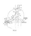
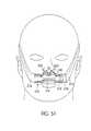
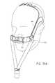
- FIG. 1is a perspective view illustrating a partial nasal assembly constructed in accordance with an embodiment of the invention mounted to a patient's head and engaged with nasal passages of the patient;
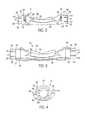
- FIG. 2is a front view of a frame of the nasal assembly shown in FIG. 1 with some parts removed for clarity;
- FIG. 3is a cross-sectional view of the frame shown in FIG. 2 ;
- FIG. 4is a side view of the frame shown in FIG. 2 ;
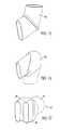
- FIG. 5is a front view of a nozzle assembly of the nasal assembly shown in FIG. 1 ;
- FIG. 6is a front cross-sectional view of the nozzle assembly shown in FIG. 5 ;
- FIG. 7is a side view of the nozzle assembly shown in FIG. 5 ;
- FIG. 8is a side cross-sectional view of the nozzle assembly shown in FIG. 5 ;
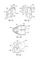
- FIG. 9is a perspective view of an embodiment of an inlet conduit and headgear connector assembly of the nasal assembly shown in FIG. 1 ;
- FIG. 10is a rear perspective view of the inlet conduit and headgear connector assembly shown in FIG. 9 ;
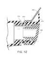
- FIG. 11is a perspective view of another embodiment of an inlet conduit and headgear connector assembly adapted to be used with the nasal assembly shown in FIG. 1 ;
- FIG. 12is a rear perspective view of the inlet conduit and headgear connector assembly shown in FIG. 11 ;
- FIG. 13is a side view illustrating an over-the-head inlet conduit routing for the nasal assembly shown in FIG. 1 ;
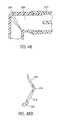
- FIG. 14is a side view illustrating an under-the-chin inlet conduit routing for the nasal assembly shown in FIG. 1 ;
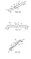
- FIG. 15is a perspective view illustrating a connector for use in routing the inlet conduits over the head of the patient
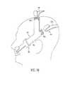
- FIG. 16is a perspective view illustrating a connector for use in routing the inlet conduits under the chin of the patient
- FIG. 17is a perspective view illustrating a flow generator connector for use in connecting the nasal assembly shown in FIG. 1 to a pressurized supply;
- FIG. 18is a side view illustrating an embodiment of headgear components for use with the nasal assembly shown in FIG. 1 ;
- FIG. 19is a schematic view illustrating a patient's nose having a substantially flat alar angle
- FIG. 20is a schematic view illustrating a patient's nose having a substantially steep alar angle
- FIG. 21is a schematic view illustrating an embodiment of a sealing zone of a nozzle
- FIG. 22is a graph illustrating average nostril ratios opening/entrance
- FIG. 23is a schematic view illustrating an embodiment for calculating a base major axis of a nozzle
- FIG. 24is a schematic view illustrating an embodiment for calculating a base minor axis of a nozzle
- FIG. 25is a partial perspective view illustrating another embodiment of a nasal assembly mounted to a patient's head and engaged with nasal passages of the patient;
- FIG. 26is a partial front perspective view of the nasal assembly shown in FIG. 25 ;
- FIG. 27is a cross-sectional view of the nasal assembly shown in FIG. 25 ;
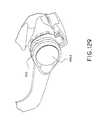
- FIG. 28is a front perspective view of a frame of the nasal assembly shown in FIG. 25 ;
- FIG. 29is a rear perspective view of the frame shown in FIG. 28 ;
- FIG. 30is a partial front perspective view of a half of the nozzle assembly of the nasal assembly shown in FIG. 25 ;
- FIG. 31is a side cross-sectional view of the nozzle assembly shown in FIG. 30 ;
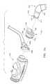
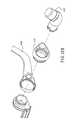
- FIG. 32is a perspective view illustrating an embodiment of an inlet conduit and headgear connector assembly of the nasal assembly shown in FIG. 25 ;
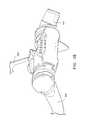
- FIG. 33is a rear perspective view of the inlet conduit and headgear connector assembly shown in FIG. 32 ;
- FIG. 34is a cross-sectional view of the inlet conduit and headgear connector assembly shown in FIG. 32 with the flexible arms in phantom;
- FIG. 35is a perspective view of a flow generator connector for use in connecting tubes for use with the nasal assembly shown in FIG. 25 to a pressurized supply;
- FIG. 36is a side view illustrating the routing of the inlet conduits of the nasal assembly shown in FIG. 25 ;
- FIG. 37is a side view illustrating the nasal assembly shown in FIG. 25 mounted to a patient's head;
- FIG. 38is a perspective view illustrating another embodiment of a nasal assembly mounted to a patient's head and engaged with nasal passages of the patient;
- FIG. 38Bis a perspective view illustrating an inlet conduit and an inlet conduit and headgear connector of the nasal assembly shown in FIG. 38 ;
- FIG. 39is a perspective view of the nasal assembly shown in FIG. 38 ;
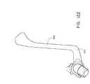
- FIG. 40is a perspective view of a frame of the nasal assembly shown in FIG. 38 ;
- FIG. 41is a perspective view of a nozzle assembly of the nasal assembly shown in FIG. 38 ;
- FIG. 42is a perspective view illustrating the nozzle assembly shown in FIG. 41 mounted to the frame to shown in FIG. 40 ;
- FIG. 43is a cross-sectional view of the nasal assembly shown in FIG. 38 ;
- FIG. 44is a side cross-sectional view of the nasal assembly shown in FIG. 38 ;
- FIG. 45is a side view illustrating the nasal assembly shown in FIG. 38 mounted to a patient's head showing two inlet configurations;
- FIG. 46is a schematic force diagram illustrating some of the forces that are developed when the nasal assembly shown in FIG. 38 is mounted to the patient's head;
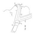
- FIG. 47is a cross-sectional view of an embodiment of an inlet conduit engaged with an embodiment of an angle connector for delivering breathable gas
- FIG. 47Bis a perspective view illustrating another embodiment of an inlet conduit
- FIG. 48is a cross-sectional view illustrating another embodiment of an inlet conduit engaged with another embodiment of a flow generator connector for delivering breathable gas;
- FIG. 48Bis perspective view illustrating another embodiment of an inlet conduit
- FIG. 49is a perspective view illustrating an embodiment of an inlet conduit of the nasal assembly shown in FIG. 38 ;
- FIG. 50is a side view illustrating the nasal assembly shown in FIG. 38 prior to engagement with nasal passages of the patient;
- FIG. 51is a front view illustrating the nasal assembly shown in FIG. 38 (in cross-section) engaged with nasal passages of the patient;
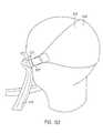
- FIG. 52is a perspective view illustrating another embodiment of a nasal assembly mounted to a patient's head and engaged with nasal passages of the patient with two inlet configurations shown;
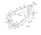
- FIG. 53is a perspective view illustrating the nasal assembly shown in FIG. 52 ;
- FIG. 54is a cross-sectional view illustrating a nozzle assembly being engaged with a frame of the nasal assembly shown in FIG. 52 ;
- FIG. 55is a perspective view illustrating an inlet conduit and headgear connector assembly of the nasal assembly shown in FIG. 52 ;
- FIG. 56is a cross-sectional view illustrating the inlet conduit and headgear connector assembly of the nasal assembly shown in FIG. 52 ;
- FIG. 57is a cross-sectional side view illustrating the nasal assembly shown in FIG. 52 about to be engaged with nasal passages of the patient;
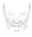
- FIG. 58is a front view illustrating the nasal assembly shown in FIG. 52 (in cross-section) being engaged with nasal passages of the patient;
- FIG. 59is a perspective view illustrating another embodiment of a nasal assembly mounted to a patient's head and engaged with nasal passages of the patient;
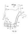
- FIG. 60is a perspective view of the nasal assembly shown in FIG. 59 removed from a patient's head;
- FIG. 61is an exploded view of a portion of the nasal assembly shown in FIG. 59 illustrating the frame, nozzle assembly, and clip thereof;
- FIG. 62is a perspective view of a portion of the nasal assembly shown in FIG. 59 illustrating the clip being engaged with the frame and nozzle assembly;
- FIG. 63is a perspective view of a portion of the nasal assembly shown in FIG. 59 illustrating the engagement between the frame, nozzle assembly, and clip;
- FIG. 64is a partial cross-sectional view of a portion of the nasal assembly shown in FIG. 59 illustrating the engagement between the frame, nozzle assembly, and clip;
- FIG. 65is a top perspective view of a portion of the nasal assembly shown in FIG. 59 ;
- FIG. 65Ais a partial enlarged view of the cushion shown in FIG. 65 ;
- FIG. 65Bis a schematic diagram illustrating force distribution according to one aspect of the present invention.
- FIG. 66is a rear perspective view of a portion of an alternative embodiment of a nasal assembly illustrating the engagement between the frame, nozzle assembly, and clip;
- FIG. 67is a rear perspective illustrating the engagement between another embodiment of the frame, nozzle assembly, and clip;
- FIG. 68is a perspective view illustrating the nozzle assembly shown in FIG. 66 being engaged with the frame shown in FIG. 66 ;
- FIG. 69is a perspective view illustrating the nozzle assembly shown in FIG. 67 being engaged with the frame shown in FIG. 67 ;
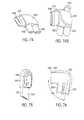
- FIG. 70is a perspective view illustrating the clip shown in FIG. 66 being engaged with the frame and nozzle assembly shown in FIG. 66 ;
- FIG. 71is a perspective view illustrating the clip shown in FIG. 67 being engaged with the frame and nozzle assembly shown in FIG. 67 ;
- FIG. 72is a perspective view of a second connector portion of the nasal assembly shown in FIG. 59 ;
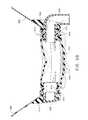
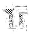
- FIG. 73is a cross-sectional view of a portion of the nasal assembly shown in FIG. 59 illustrating the engagement between the frame, second connector portion, and angle connector;
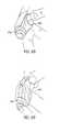
- FIG. 74is a perspective view of an angle connector of the nasal assembly shown in FIG. 59 ;
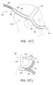
- FIG. 74Bis a perspective similar to FIG. 74 but at a different angle
- FIG. 75is a side view of the angle connector shown in FIG. 74 ;
- FIG. 76is a cross-sectional view of the angle connector shown in FIG. 74 ;
- FIG. 76Aillustrates another embodiment of the present invention
- FIG. 76Bis an exploded view of FIG. 76A ;
- FIG. 76Cillustrates a second connector portion of the assembly of FIG. 76A ;
- FIG. 76Dillustrates an angle connector used in the assembly of FIG. 76A ;
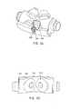
- FIG. 77is a perspective view of a flow generator connector of the nasal assembly shown in FIG. 59 ;
- FIG. 78is a cross-sectional view of the flow generator connector shown in FIG. 77 ;
- FIG. 79is a cross-sectional view of an embodiment of an inlet conduit of the nasal assembly shown in FIG. 59 ;
- FIG. 80is a perspective view of headgear yoke of the headgear assembly of the nasal assembly shown in FIG. 59 ;
- FIG. 81is a perspective view illustrating engagement between the headgear yoke ( FIG. 80 ) and angle connector ( FIG. 74 );
- FIG. 82is a cross-section through line 82 - 82 of FIG. 81 ;
- FIG. 83is a perspective view of a headgear buckle of the nasal assembly shown in FIG. 59 ;
- FIG. 84is a perspective view of the nasal assembly shown in FIG. 59 illustrating the routing of the headgear assembly
- FIG. 85is another perspective view of the nasal assembly shown in FIG. 59 illustrating the routing of the headgear assembly
- FIG. 86is a top view illustrating a nasal assembly constructed in accordance with an embodiment of the invention.
- FIG. 87is a side view of the nasal assembly shown in FIG. 86 ;
- FIG. 88is a bottom view of the nasal assembly shown in FIG. 86 ;
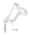
- FIG. 89is an exploded view of a portion of the nasal assembly shown in FIG. 86 ;
- FIG. 90is a perspective view of a portion of an embodiment of a nasal assembly
- FIG. 91is a top view of a headgear connector according to an alternative embodiment of the invention.
- FIG. 92is a perspective view of an upper portion of a central conduit of the nasal assembly shown in FIG. 90 ;
- FIG. 93is a top view of the upper portion of the central conduit shown in FIG. 92 ;
- FIG. 94is a perspective view of a lower portion of a central conduit of the nasal assembly shown in FIG. 90 ;
- FIG. 95is a bottom view of the lower portion of the central conduit shown in FIG. 94 ;
- FIG. 96is a perspective view of an inlet conduit of the nasal assembly shown in FIG. 86 ;
- FIG. 96Ais a schematic view of a Y-shaped inlet connector of the nasal assembly shown in FIG. 86 ;
- FIG. 97is a perspective view of an inlet connector of the nasal assembly shown in FIG. 86 ;
- FIG. 97Ais a schematic view of the nasal assembly shown in FIG. 86 with the nozzles in a first position adjacent to the nasal passages of the patient;
- FIG. 97Bis a schematic view of the nasal assembly shown in FIG. 86 with the nozzles in a second position in sealing engagement with the nasal passages of the patient;
- FIG. 98is a perspective view of another embodiment of a nasal assembly.
- FIG. 99is an enlarged perspective view of nozzles and a gusset portion of the nasal assembly shown in FIG. 98 ;
- FIG. 100is an enlarged perspective view of inlet conduits of the nasal assembly shown in FIG. 98 ;
- FIG. 101is a front perspective view illustrating the nasal assembly shown in FIG. 98 mounted to a patient's head;
- FIG. 102is a rear perspective view illustrating the nasal assembly shown in FIG. 98 mounted to a patient's head;
- FIG. 103is a front perspective view illustrating the nasal assembly shown in FIG. 98 engaged with nasal passages of the patient;
- FIG. 104is a side perspective view illustrating the nasal assembly shown in FIG. 98 engaged with the nasal passages of the patient;
- FIG. 105is a side view illustrating the nasal assembly shown in FIG. 98 engaged with the nasal passages of the patient;
- FIG. 106is a front perspective view illustrating the nasal assembly shown in FIG. 98 engaged with nasal passages of the patient;
- FIG. 107is a perspective view of another embodiment of a nasal assembly mounted to a patient's head
- FIG. 107-1is a perspective view of yet another embodiment of the present invention.
- FIG. 107-2is a perspective view of yet another embodiment of the present invention.
- FIGS. 107A-107Cillustrate yet another alternative embodiment of the present invention.
- FIGS. 107D and 107Eillustrate still another embodiment according to the present invention.
- FIG. 107Fillustrates another alternative embodiment of the present invention.
- FIGS. 107G and 107Hillustrate another alternative embodiment of the present invention.
- FIG. 107Iillustrates still another embodiment of the present invention.
- FIG. 107Jillustrates yet another alternative embodiment of the present invention.
- FIGS. 107K and 107Lillustrate yet another embodiment of the present invention.
- FIGS. 107M-107Qillustrate cross-sections of alternative nozzles according to the present invention
- FIG. 107Rillustrates a perspective view of two nozzles like the nozzle shown in FIG. 107Q ;
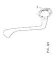
- FIG. 108is a perspective view of yet another embodiment of a nasal assembly
- FIGS. 108A and 108Billustrate a tube retainer according to an embodiment of the present invention
- FIG. 108Cillustrates another tube retainer according to an embodiment of the present invention.
- FIG. 109is an isometric view illustrating a portion of the nasal assembly shown in FIG. 108 ;
- FIG. 110is a cross-sectional view of a portion of a nasal assembly according to the present invention.
- FIGS. 110-1 and 110 - 2illustrate cross-sectional views of a vent aperture according to the present invention
- FIG. 110Ais a partial enlarged cross-sectional view of the left hand side of FIG. 110 ;
- FIG. 110Bis an partial enlarged cross-sectional view of the right hand side of FIG. 110 ;
- FIG. 111is an exploded perspective view showing the interface between seal ring and elbow swivel according to an embodiment of the present invention.
- FIG. 112is a partial cross-sectional view of a portion of the mask assembly shown in FIG. 108 ;
- FIG. 113illustrates still another embodiment of the present invention with an integral plug and seal assembly
- FIGS. 114-126illustrate yet another embodiment of the present invention.
- FIGS. 127-130illustrate still another embodiment of the present invention.
- FIGS. 131-133illustrate yet another swivel elbow according to an embodiment of the present invention.
- FIGS. 134-135illustrate further alternative embodiments of the present invention.
- FIG. 1shows an embodiment of a nasal assembly 10 structured to deliver breathable gas to nasal passages 12 of a patient's nose 14 .
- the nasal assembly 10includes a frame 16 and a nozzle assembly 18 that may be permanently or removably connected to the frame 16 .
- a headgear assembly 20(see FIG. 18 ) is preferably removably attached to connection assembly 22 to maintain the frame 16 and nozzle assembly 18 in a desired adjusted position on the patient's face.
- Inlet conduitsare also removably attached to the frame 16 by a connection assembly 22 to deliver breathable gas into the frame 16 and nozzle assembly 18 for breathing by the patient.
- the headgear assembly 20 and inlet conduitsare removably attached to the frame 16 by an inlet conduit and headgear connection assembly 22 .
- the connection assembly 22includes first connector portions 24 (see FIGS. 2 and 3 ) provided by the frame 16 and second connector portions 26 adapted to be removably coupled with the first connector portions 24 .
- the second connector portions 26are removably connected to the headgear assembly 20 and the inlet conduits, as will be further discussed.
- the frame 16includes a main body 28 that provides a central opening 30 for accommodating the nozzle assembly 18 .
- the frame 16also includes side frame members 32 provided on each lateral side of the main body 28 .
- the side frame members 32are preferably formed in one piece with the main body 28 of the frame 16 .
- the frame 16is a rigid or semi-rigid structure formed from a polymer material.
- the frame 16may be semi-rigid to allow flexibility of the frame 16 with respect to the patient's face in use.
- the frame 16may also be semi-rigid in certain regions for customized flex in certain regions of the frame 16 .
- Each side frame member 32includes a first connector portion 24 that is integrally formed therewith.
- the first connector portion 24includes a connecting section 34 and an indexing section 36 .
- the connecting section 34is structured to interlock with the second connector portion 26 to prevent axial disengagement of the second connector portion 26 from the first connector portion 24 .
- the indexing section 36is structured to ratchet/detent with the second connector portion 26 to allow selective circumferential adjustment of the second connector portion 26 with respect to the first connector portion 24 about an axis during fit whilst remaining “locked” in adjusted position during usage.
- each side frame member 32includes a series of grooves or slots 37 that separates the connecting section 34 into a plurality of resiliently flexible arms 38 that are structured to flex radially inwardly and outwardly.
- Each arm 38provides a rib portion 40 at the free end thereof.
- the rib portions 40 of the plurality of arms 38are adapted to engage with corresponding portions of the second connector portion 26 for coupling the first and second connector portions 24 , 26 with one another.
- the first and second connector portions 24 , 26interlock with one another to prevent accidental disengagement of the second connector portion 26 from the first connector portion 24 if a force is applied to the second connector portion 26 axially away from the first connector portion 24 .
- the first and second connector portions 24 , 26mate with one another to provide a good seal.
- the indexing section 36 of each side frame member 32includes a plurality of teeth 42 .
- the teeth 42are structured so as to selectively engage a tooth 44 provided on the second connector portion 26 (see FIGS. 9 and 10 ).
- the second connector portion 26can be rotated to a desired position with respect to the frame 16 .
- the tooth 44 on the second connector portion 26engages between selective teeth 42 provided on the indexing section 36 in the desired position and rotationally locks the second connector portion 26 with respect to the first connector portion 24 and hence the frame 16 .
- the usercan manually change the position of the tooth 66 and the teeth 42 .
- the teeth 42 of the indexing section 36can be configured so that when a predetermined torque is applied to the second connector portion 26 , the teeth 42 will automatically force the tooth 44 of the second connector portion 26 outwardly to allow rotation of the second connector portion 26 until the torque is removed and the teeth 42 reengage with the tooth 44 of the second connector portion 26 .
- the second connector portion 26can thus be rotationally adjusted or indexed with respect to the frame 16 within a predetermined angle.
- the angle of available rotational adjustmentcan be altered as desired by altering the number and positioning of the teeth 42 on the indexing section 36 .
- the adjustment angle rangeallows the patient to adjust the position of the nozzle assembly 18 relative to the nose of the patient.
- nozzle assembly 18is formed from a one part molded silicone piece that attaches to frame 16 .
- the adjusting or indexing operationis oriented perpendicular to the connecting operation in order to minimize potential disengagement of the second connector portion 26 from the first connector portion 24 .
- the main body 28includes opposing side walls 46 that define the central opening 30 for accommodating the nozzle assembly 18 .
- the side walls 46are adapted to engage with corresponding portions of the nozzle assembly 18 for coupling the nozzle assembly 18 and the frame 16 with one another, as will be further discussed.
- the nozzle assembly 18includes a base portion 48 and a pair of nozzles 50 attached thereto.
- the base portion 48has side walls 52 adapted to sealingly engage with the side walls 46 of the frame 16 and a central wall 54 .
- the pair of nozzles 50each have a first portion 56 and a second portion 58 .
- the first portion 56is attached to the central wall 54 of the base portion 48 in communication with respective outlet openings provided in the central wall 54 .
- the second portion 58is structured to sealingly engage with nasal passages 12 of the patient's nose 14 in use and to provide a seal between the nasal assembly 10 and the patient's nasal passages 12 .
- the nozzle assembly 18 and the frame 16together form a conduit for directing breathable gas to the patient's nose through the pair of nozzles 50 .
- the nozzle assembly 18is removably attached to the frame 16 with a snap, e.g., snap-fit, push-pin fit, or stretch over fit, which allows for simple assembly.
- the side walls 52 of the base portion 48may include a rib or groove/recess that is structured to interlock with a recess/rib provided on respective side walls 46 of the frame 16 with a snap-fit.
- the nozzle assembly 18may be removably attached to the frame 16 in any other suitable manner, e.g., friction or interference fit and/or a tongue and groove arrangement, as is known in the art.
- the nozzle assembly 18may be rigidly coupled to the frame 16 by an adhesive or fasteners, for example.
- the nozzle assembly 18may be formed in one piece with the frame 16 , or over-molded. That is, the nozzle assembly and frame may be a one-piece structure with different thicknesses and hardnesses to add rigidity.
- the nozzle assembly 18is flexible, to thereby allow relative movement between the nozzle assembly 18 and the frame 16 , for increased comfort and accommodation of variations in patient facial features.
- the base portion 48is structured such that it can expand and contract to alter a distance between the frame 16 and the pair of nozzles 50 , as will be further discussed below.
- the central wall 54is preferably made of a resilient and/or flexible material structured to deform, e.g., inflate upon introduction of pressurized gas, from a generally flat configuration to a generally curved configuration in use to thereby move the nozzles 50 towards the patient's nose.
- Other portions of the base portion 48e.g., side walls 52 , may be structured to deform/inflate as well.
- the base portion 48has a generally dog-bone shape.
- the base portion 48may have any suitable shape, including shapes to avoid contact with sensitive regions of the patient's face, e.g., notched base shape, to prevent contact with the patient's septum or otherwise minimize contact pressure in these sensitive regions.
- the second portion 58 of the nasal assemblyis contoured (e.g., tapered, cone-shaped, truncated hollow cone, etc.) with a portion that seals on the underside of the nostrils (e.g., an area about the rim of the nostril openings) and another portion that enters into the nasal passage of the patient's nose in use.
- the nozzles 50may be in the form of nasal prongs, cannula, or nasal puffs, for example, and may sealingly engage with the nasal passages 12 in any suitable manner.
- the nozzles 50may seal within the nasal passages 12 , against the nasal passages 12 , around the nasal passages 12 , or combinations thereof.
- the nozzles 50may be contoured to match the interior anatomical profile of the patient's nose.
- different size and/or shape nozzlese.g., small, medium, and large, may be provided to accommodate a range of patient's noses.
- the first portion 56 of the nozzles 50have a reduced cross-section with respect to the second portion 58 to allow the nozzles 50 to move relative to the base portion 48 , and hence the frame 16 , for increased comfort and accommodation of variations in patient facial features.
- the nasal assembly 10uses patient-customized nozzles which may be removably mounted to the base portion 48 or the frame 16 .
- the nozzlesare constructed from a substantially flexible polymer material, such as a silicone elastomer.
- a unique nozzlecan be made match each patient's nose by first scanning their nose, either in situ or remotely, and then using the data for manufacture of the interface, for example, a mold maker. Scanning can be done using either non-contact or contact methods. Non-contact, for example photographically, or by physical contact with a probe or by collecting an impression of the inside of the nares of the desired contact interface. Once a pair of suitable nozzles are made, they are sent to the customer to be fitted to a patient.
- pre-formed or customized shapeis that cross-sectional area may be maximized to reduce flow impedance. Also, the use of pre-formed shapes improves comfort and increased stiffness materials such as semi-rigid plastics may be used that have greater resistance to distorting, thus minimizing nozzle distortion of the patient's nares. Further, rigid plastics may be used that allows thin wall sections and allows flexibility of the nozzle due to its connection to the base portion 48 , e.g., the base portion 48 is soft and compliant.
- the nozzles 50are molded in one piece with the base portion 48 from deformable and inflatable materials.
- the nozzles 50 and base portion 48may be constructed from a soft, flexible, skin-compatible material such as silicone.
- the nozzles 50 and base portion 48may be formed, for example, in an injection, compression, and/or transfer molding process as is known in the art.
- the nozzles 50 and base portion 48may be formed with any suitable material and may be formed by any suitable process.
- the base portion 48 and nozzles 50may be formed separately and permanently attached to one another with an adhesive and/or mechanical fasteners, for example.
- the base portion 48 and nozzles 50may be formed separately and removably attached to one another.
- each second connector portion 26is a unitary polymeric piece (e.g., silicone) formed by injection molding, compression molding, or blow-molding, for example.
- Each second connector portion 26includes a main body having a front portion 60 and a rear portion 62 .
- the front portion 60is interlocked with the first connector portion 24 provided on the frame 16 and the rear portion 62 is removably connected to the headgear assembly 20 and the inlet conduits.
- the front and rear portions 60 , 62are angled with respect to one another such that the second connector portions 26 follow the contour of the patient's face in use, as shown in FIG. 1 .
- the front portion 60provides a generally cylindrical conduit 64 having a recess 66 on an inner surface thereof.
- the recess 66is adapted to receive the rib portions 40 of the plurality of arms 38 on the first connector portion 24 . That is, the plurality of arms 38 are forced towards one another as the first connector portion 24 is inserted into the conduit 64 of the second connector portion 26 .
- the arms 38can spring outwardly into the recess 66 to provide an interlocking engagement between the first and second connector portions 24 , 26 .
- the patientsimply pulls the second connector portion 26 axially outwardly from the frame 16 with sufficient force to release the rib portions 40 from the recess 66 .
- the front portion 60also provides a cross-bar 68 that provides the tooth 44 of the second connector portion 26 .
- the tooth 44engages the plurality of teeth 42 provided by the first connector portion 24 to allow selective rotational adjustment of the second connector portion 26 with respect to the first connector portion 24 and hence the frame 16 .
- the cross bar 68acts as a leaf spring to resiliently bias the tooth 44 into engagement with the teeth 42 of the first connector portion 24 .
- the rear portion 62 of the second connector portion 26includes a cross-bar 70 that forms an opening through which a strap of the headgear assembly 20 may pass and be removably connected.
- the cross-bar 70may be configured to provide more than one opening for connection to the headgear assembly 20 .
- the second connector portion 26includes a cross-bar 71 that provides a pair of openings through which a pair of straps of the headgear assembly 20 may pass and be removably connected.
- the rear portion 62also provides an elongated conduit 72 adapted to be connected to an inlet conduit that delivers breathable gas to the frame 16 and nozzle assembly 18 .
- the conduit 72 of the rear portion 62has a different cross-sectional shape than the conduit 64 of the front portion 60 to facilitate connection to the inlet conduit.
- the conduits 72 , 64 of the rear and front portions 62 , 60may have similar cross-sectional areas.
- FIGS. 13 and 14schematically illustrate the routing of on of the first pair of inlet conduits 74 and one of the second pair of inlet conduits 76 of the nasal assembly 10 .
- First ends of the first pair of conduits 74are connected to respective conduits 72 of the second connector portions 26 .
- Second ends of the first pair of conduits 74are connected to respective first ends of the second pair of inlet conduits 76 .
- Second ends of the second pair of inlet conduitsare connected to a pressurized supply that supplies pressurized breathable gas.
- pressurized gascan pass through the first and second pairs of inlet conduits 74 , 76 into the frame 16 and base portion 48 , and through the nozzles 50 for breathing by the patient.
- the frame 16includes an exhaust vent 78 that protrudes slightly outwardly from the frame 16 and includes a series of openings for CO 2 washout.
- the first and second pairs of inlet conduits 74 , 76may be routed to extend upwardly over the head of the patient.
- the first pair of inlet conduits 74may have a length of about 120-160 mm, preferably about 140 mm and the second pair of inlet conduits 76 may have a length of about 160-200 mm, preferably about 180 mm.
- other length dimensionsmay be used as well.
- the first pair of inlet conduits 74are angled about 30° from horizontal and the second pair of inlet conduits 76 are angled about 90° from horizontal, or about 60° from the first pair of inlet conduits 74 .
- the first and second pairs of inlet conduits 74 , 76may have any suitable length and may be routed in any suitable manner to extend upwardly over the head of the patient.
- the first and second pairs of inlet conduits 74 , 76may be routed to extend downwardly under the chin of the patient.
- the first pair of inlet conduits 74may have a length of about 40-80 mm, preferably about 60 mm and the second pair of inlet conduits 76 may have a length of about 180-220 mm, preferably about 200 mm.
- the first pair of inlet conduitsare angled about ⁇ 20° to 40° from horizontal, preferably about 30° from horizontal and the second pair of inlet conduits 76 are angled about ⁇ 90° from horizontal, or about ⁇ 120° from the first pair of inlet conduits 74 .
- the first and second pairs of inlet conduitsmay have any suitable length and may be routed in any suitable manner to extend upwardly over the head of the patient.
- FIGS. 15 and 16illustrate embodiments of connectors structured to interconnect the second ends of the first pair of conduits 74 with respective first ends of the second pair of inlet conduits 76 .
- the connector 80 shown in FIG. 15is suitably angled to route the conduits 74 , 76 upwardly over the head of the patient.
- the connector 82 shown in FIG. 16is suitably angled to route the conduits 74 , 76 downwardly under the chin of the patient.
- FIG. 17illustrates a flow generator connector 84 structured to interconnect the second ends of the second pair of inlet conduits 76 with a pressurized supply.
- the flow generator connector 84includes a first conduit 86 structured to connect to one of the second pair of inlet conduits 76 and a second conduit 88 structured to connect to the other of the second pair of inlet conduits 76 .
- the flow generator connector 84includes a third conduit 90 structured to connect to a conduit that is connected to the pressurized supply.
- the third connector 90may include a swivel mechanism or flexible joint to allow relative movement between the flow generator connector 84 and the conduit associated with the pressurized supply.
- the inlet conduits 74 , 76provide a single air flow channel.
- the conduits 74 , 76 , connector portions 24 , 26 , and connectors 80 , 82 , 84may be structured to provide more than one air flow channel.
- the inlet conduits 74 , 76may be manufactured in any suitable manner.
- the conduits 74 , 76may be extruded or the conduits may be injection molded.
- the inlet conduits 74 , 76may be structured from any suitable polymeric material such as silicone or a thermoplastic elastomer, such as Krayton®, for example.
- the inlet conduits 74 , 76may be formed of crush-resistant, anti-crush or anti-kinking tubing such as that disclosed in U.S. Pat. No. 6,044,844, the entirety of which is incorporated herein by reference.
- the inlet conduits 74 , 76 and respective connector portions 24 , 26 and/or connectors 80 , 82 , 84may be retained with a friction-type fit, mechanical fasteners, adhesive, co-molded, insert molded, or any other suitable means.
- pressurized gasenters through connector 90 of the flow generator connector 84 and proceeds through the second set of inlet conduits 76 into the first set of inlet conduits 74 and into both side frame members 32 of the frame 16 .
- Airpasses through the frame 16 , into the base portion 48 and nozzles 50 , and into the nasal passages 12 of the patient. Exhaust gasses from the patient's nose can exit through the exhaust vent 78 provided in the frame 16 .
- the headgear assembly 20is removably attached to second connector portion 26 attached to the frame 16 to maintain the frame 16 and nozzle assembly 18 in a desired adjusted position on the patient's face.
- the headgear assembly 20includes two side portions 92 with a rear portion 94 connecting the side portions 92 .
- Each side portion 92comprises a side strap 96 .
- the rear portion 94which interconnects the two side portions 92 , includes an upper strap 98 that passes over the top of the patient's head and a rear strap 100 that passes around the rear portion of the patient's head.
- the headgear assemblymay be permanently attached to the frame.
- Each side strap 96is removably connected to the second connector portion 26 . Specifically, the end portion of each side strap 96 has a reduced width that enables the side strap 96 to be wrapped around the cross-bar 70 provided on the second connector portion 26 . Fastening of the side straps 96 to respective cross-bars 70 may be assisted by use of a hook and loop material, such as Velcro®. Thus, the side straps 96 may be adjusted with respect to the second connector portion 26 for proper fit.
- the upper strap 98 and rear strap 100are removably connected to the side straps 96 by buckles 102 provided on the side straps 96 .
- the buckles 102can be attached to the side straps 96 with adhesives, stitching and/or other known manners.
- the buckles 102includes a single cross-bar to enable the upper and rear straps 98 , 100 to be coupled therewith.
- any other suitable buckle arrangementmay be provided to interconnect the side straps 96 with the upper and rear straps 98 , 100 .
- the straps 96 , 98 , 100 of the headgear assembly 20may be constructed from a soft, flexible composite material.
- the straps 96 , 98 , 100may include two layers of material with one of the layers made of a fabric material and the other of the layers made of a polymeric material.
- the headgear assembly 20may include one or more stiffeners attached thereto in order to add to the rigidity of the headgear assembly 20 in certain planes and directions, which would assist in stabilizing the nasal assembly 10 on the head of the patient during use.
- the headgear assembly 20may include any number of straps to support the nasal assembly 10 on the patient's head.
- each of the side straps 96may include a pair of straps to be used with the second connector portion 26 shown in FIGS. 11 and 12 .
- the headgear assembly 20may be constructed as a one piece structure.
- the base portion 48extends outwardly from the frame 16 to provide additional surface area or footprint area. As air under pressure enters the frame 16 , the base portion 48 inflates, which moves the nozzles 50 into sealing engagement with the nasal passages 12 of the patient. For example, expansion of the base portion in the direction of the nostrils causes the nozzles to move into sealing engagement with the nasal passages.
- a portion of the sealing forcemay be provided by the first portion 56 , which may be pre-loaded, like a spring, against the patient's nostril.
- the base portion 48is structured such that it can expand and contract to alter a distance between the frame 16 and the nozzles 50 .
- the base portion 48moves the nozzles 50 between a first position in which the nozzles 50 are adjacent to the nasal passages 12 of the patient and a second position in which the nozzles 50 are moved into sealing engagement with the nasal passages 12 of the patient.
- the nozzles 50are spaced from the nasal passages 12 of the patient or in light contact therewith.
- the base portion 48is inflated and moves the nozzles 50 into sealing engagement with the nasal passages 12 of the patient to form a seal between the nasal assembly 10 and the patient's nasal passages 12 .
- the gas pressureis increased, the force applied to the underside of the nasal passages is increased through the base portion 48 .
- the base portion 48provides additional surface area or footprint area to the frame 16 , which in turn provides an additional force on the nozzles 50 which increases the sealing efficiency of the nozzles 50 . That is, the base portion 48 is configured and positioned to force the nozzles 50 into contact with the patient's nose.
- the force or pressure on the patient's noseis proportional to: (a) the pressure in the frame 16 and nozzle assembly 18 ; (b) additional surface area of the base portion 48 ; and/or (c) the preload from materials and geometry of nozzles 50 or base portion 48 , including central wall 54 and first portion 56 of the base portion 48 .
- the surface area of the base portion 48may be varied, e.g., to vary the force or pressure applied to the patient's nose.
- the side walls 52 of the base portion 48may act as a spring structure to provide a component of force on the patient's face through the nozzles 50 .
- the forcemay be tailored by adjusting the thickness of the side walls 52 .
- the thickness of the side walls 52may be varied in conjunction with the additional surface area provided by the base portion 48 .
- the force provided by the base portion 48 along with the air pressureprovides an effective sealing force against the nasal passages 12 of the patient.
- the base portion 48reduces the headgear assembly tension required to achieve a suitable seal. That is, the sealing force applied to the patient's nose may be provided by the base portion 48 , preload and/or air pressure, and not by the tension from the headgear assembly 20 . This improves patient comfort as well as sealing properties.
- the headgear assembly 20it is desirable when adjusting the headgear assembly 20 to bring the nozzles 50 only near or in very light contact with the patient's nose. In this way, the base portion 48 is not compressed substantially. In use, contact will need to be sufficient for seal.
- the base portion 48also provides a decoupling joint between the frame 16 and the nozzles 50 , thus allowing some relative movement between the nasal assembly 10 and the user's face.
- the nozzles 50can accommodate small variations in the shape of the patient's nasal features without undue force, and can account for small movement of the nasal assembly 10 relative to the patient's nose during use, while maintaining an effective seal.
- connection assembly 22 including the first and second connector portions 24 , 26enables the position of the nozzles 50 to be easily adjusted with respect to the patient's nose. Specifically, the patient can rotate the frame 16 with respect to the headgear assembly 20 to adjust the positioning of the nozzles 50 .
- the base portion 48need not be a single base form discussed above, but can have alternative configurations.
- the base portion 48may be in the form of two or more base portions provided in series.
- end portions of the base portion 48are angled with respect to one another so as to angle the nozzles 50 attached thereto with respect to one another.
- This anglealso referred to as an alar angle
- the nozzle assembly 10 shown in FIGS. 5 and 6has an alar angle in the range of 135-155°, preferably about 145°, to accommodate a substantially flat nose (see FIG. 19 ).
- the alar anglemay be in the range of 70-90°, preferably about 80°, to accommodate a substantially pointed or steep nose (see FIG. 20 ).
- the alar anglemay have any suitable size to accommodate any shape nose. Movement of the nozzles helps accommodate steeper noses.
- the sealing zone of the nozzle 50may extend at an angle from about half the height of the nozzle 50 .
- the nozzle 50has a height of about 9 mm.
- the nozzle 50may have any suitable height and may provide any suitable sealing zone.
- the nozzles 50are appropriately spaced with respect to one another on the base portion 48 .
- the spacingis based on the size of the nozzles 50 and the available space on the base portion 48 .
- the size of the nozzles 50is based on the patient's nostril circumference.
- ellipse ratiosmay be used to determine nozzle geometry (see FIG. 22 ).
- an ellipse ratio of 0.7(Average+1 Standard Deviation) may be used to determine nozzle geometry.
- the base major axis of the nozzlemay be defined by measurement from the center of a nostril to the upper lip.
- the base minor axis of the nozzlemay be defined by the maximum space available between nozzles.
- any other suitable methodmay be used to determine the size of the nozzles.
- the above-noted alar angle, sealing zone, spacing between nozzles, and size of the nozzlesmay be determined so that a wide range of patients can be accommodated. Also, different size nasal assemblies, e.g., small, medium, and large, may be provided to accommodate different size patients. However, any other suitable measurements and methods may be used to provide a nasal assembly that fits the widest range of patients.
- the nasal assembliesare structured such that the stability forces that act to maintain the nasal assembly on the patient's face are separated or at least better distinguished from the sealing forces that act to maintain a seal between the nasal assembly and the patient's face.
- the sealing forcesact on more sensitive regions of the patient's face, e.g., nose
- the stability forcesact on less sensitive regions of the patient's face, e.g., upper lip, cheeks and back of the patient's head.
- the stability forcestend to be higher than the sealing forces.
- the nasal assemblyis structured such that the higher stability forces are substantially separated from the lower sealing forces to improve patient comfort.
- the nasal assemblyis structured such that stability forces applied by the headgear assembly are distributed to the back of the patient's head, the patient's cheeks, and the patient's upper lip to maintain the nasal assembly on the patient's face in use.
- the nasal assemblyincludes the nozzle assembly structured to apply sealing forces to nasal passages of the patient's nose in use.
- Features of the headgearhave been designed to achieve substantially independent adjustment of sealing and stability forces. Thus, the higher stability forces do not effect the more sensitive regions of the patient's face, e.g., nose, as much.
- Another aspect of the inventionrelates to the association between the nozzles and the base portion to apply a force to the patient's face.
- the base portionis structured to apply a component of force to the patient's face and the nozzles are structured to apply a component of force to the patient's face.
- the base portionmay have a substantially rigid structure such that it applies a relatively small component of force on the patient's face. That is, the base portion may not be substantially inflatable or expandable when pressurized by a gas.
- the nozzlesmay have a flexible structure such that they provide a relatively larger component of force on the patient's face. That is, the first portion 56 of the nozzles 50 may act as a spring structure, e.g., spring-loaded or resilient, to provide a component of force on the patient's face through the nozzles 50 .
- spring-loadedit is meant that the nozzles apply a predetermined force against the user's nasal sealing area, for sealing purposes.
- nozzlesare preloaded before introducing pressurized gas to provide a sealing force with the user.
- the base portion and nozzlestogether provide a force to provide a seal between the nasal assembly and the patient's nasal passages.
- the base portionmay have a flexible structure such that it applies a relatively large component of force on the patient's face when inflated.
- the nozzlesmay have a more rigid structure such that they apply a relatively smaller component of force on the patient's face.
- the nozzle assemblymay be structured such that the nozzles are spring-loaded or resilient to apply a sufficient component of force for sealing.
- the base portioncan be structured more rigidly to apply a smaller component of force for sealing.
- the nozzle assemblymay be structured such that the base portion is sufficiently expandable to apply a sufficient component of force for sealing and the nozzles can be structured more rigidly to apply a smaller component of force for sealing.
- the nozzlesmay be substantially rigid, e.g., where the nozzles are tailored for a particular user. This alternative can be combined with the earlier embodiment (relating rigid base portions and spring-loaded (e.g. preloaded) nozzles).
- the base of the nozzlemay be structured to provide a variable amount of preload, and the sealing portion of the nozzle, preferably tailored to the user, may be relatively more rigid.
- the nozzle assemblymay be structured such that the base portion and nozzles provide substantially similar components of force for sealing.
- FIGS. 25-37illustrate another embodiment of a nasal assembly, indicated as 210 .
- the nasal assembly 210includes a frame 216 and a nozzle assembly 218 that is removably connected to the frame 216 .
- a headgear assembly 220(see FIG. 37 ) is removably attached to the frame 216 to maintain the frame 216 and nozzle assembly 218 in a desired adjusted position on the patient's face.
- Inlet conduits 274are also removably attached to the frame 216 to deliver breathable gas into the frame 216 and nozzle assembly 218 for breathing by the patient.
- the headgear assembly 220 and inlet conduits 274are removably attached to the frame 216 by an inlet conduit and headgear connection assembly 222 .
- the connection assembly 222includes first connector portions 224 (see FIGS. 28 and 29 ) provided by the frame 216 and second connector portions 226 adapted to be removably coupled with the first connector portions 224 .
- the second connector portions 226are removably connected to the headgear assembly 220 and the inlet conduits 274 , as will be further discussed.
- the frame 216includes a main body 228 that provides a central opening 230 for accommodating the nozzle assembly 218 .
- the frame 216also includes side frame members 232 provided on each lateral side of the main body 228 .
- Each side frame member 232includes a first connector portion 224 that is integrally formed therewith.
- the first connector portion 224is in the form of a conduit 264 having a recess 266 on an inner surface thereof.
- the frame 216also includes a series of openings 278 for CO 2 washout.
- the nozzle assembly 218forms a conduit that includes a main body 219 and opposing end portions 221 (only half of the nozzle assembly 218 is shown in the figures). As best shown in FIG. 27 , the end portions 221 are stretched over the side frame members 232 of the frame 216 with the main body 219 in covering relation to the main body 228 and central opening 230 of the frame 216 . When the nozzle assembly 218 is attached to the frame 216 , the frame 216 adds rigidity to the relatively flexible nozzle assembly 218 .
- the main body 219 of the nozzle assembly 218includes a gusset portion 248 and a pair of nozzles 250 attached thereto.
- the nozzles 250may be designed and structured in a similar manner to the nozzles 50 described above.
- the main body 219 of the nozzle assemblyalso includes a series openings 223 that align with the series of openings 278 provided on the frame 216 for CO 2 washout.
- the second connector portion 226includes a main body having a front portion 260 and a rear portion 262 .
- the front portion 260includes a plurality of resiliently flexible arms 238 that are structured to flex radially inwardly and outwardly.
- Each arm 238provides a rib portion 240 at the free end thereof.
- the rib portions 240 of the plurality of arms 238are adapted to engage within the recess 266 of the first connector portion 224 for coupling the first and second connector portions 224 , 226 with one another.
- the connection assembly 222does not provide an indexing section.
- the second connector portion 226may rotate with respect to the first connector portion 224 for an infinite amount of settings for alignment of the nozzles 250 with respect to the nasal passages of the patient. The settings may be locked by way of friction, for example.
- the rear portion 262 of the second connector portion 226includes a cross-bar 270 that forms an opening through which a strap of the headgear assembly 220 may pass and be removably connected.
- the rear portion 262also provides a pair of conduits 272 adapted to be connected to an inlet conduit that delivers breathable gas to the frame 216 and nozzle assembly 218 .
- the nasal assembly 210includes a pair of inlet conduits 274 (only one of the inlet conduits 274 being visible in FIG. 36 ). First ends of the pair of conduits 274 are connected to respective second connector portions 226 connected to the frame 216 . Second ends of the pair of conduits 274 are connected to a pressurized supply that supplies pressurized breathable gas. As shown in FIGS. 36 and 37 , the pair of inlet conduits 274 are routed to extend upwardly over the head of the patient. However, the pair of inlet conduits 274 may be routed in any suitable manner, e.g., routed to extend downwardly under the chin of the patient.
- pressurized gascan pass through the pair of inlet conduits 274 into the frame 216 and nozzle assembly 218 , and through the nozzles 250 for breathing by the patient.
- FIG. 35illustrates a flow generator connector 284 structured to interconnect the second ends of the pair of inlet conduits 274 with a pressurized supply.
- the flow generator connector 284includes a pair of first conduits 286 structured to connect to one of the pair of inlet conduits 274 and a pair of second conduits 288 structured to connect to the other of the pair of inlet conduits 274 .
- the flow generator connector 284includes a third conduit 290 structured to connect to a conduit that is connected to the pressurized gas, air, or fluid supply.
- the third connector 290may include a swivel or flexible joint mechanism to allow relative movement between the flow generator connector 284 and the conduit associated with the pressurized supply.
- the third connector 290may include a ball and socket joint so that when the third connector 290 is on top of the patient's head in an over the head configuration, the tube pull is minimized.
- the inlet conduits 274provide a dual air flow channel with a central support wall to prevent kinking and occlusion.
- the conduits 274 , connector portions 224 , 226 , and connector 284may be structured to provide one air flow channel or more than two air flow channels.
- the headgear assembly 220is removably or fixedly attached to second connector portion 226 attached to the frame 216 to maintain the frame 216 and nozzle assembly 218 in a desired adjusted position on the patient's face.
- the headgear assembly 220includes two side portions 292 (only one of the side portions 292 being visible in FIG. 37 ) with a rear portion 294 connecting the side portions 292 .
- Each side portion 292comprises a side strap 296 .
- the rear portion 294which interconnects the two side portions 292 , includes an upper strap 298 that passes over the top of the patient's head and a rear strap 299 that passes around the rear portion of the patient's head.
- Upper and rear strap 298 , 299can be adjusted for fit and can be a single strap or loop.
- the headgear assemblymay be permanently attached to the frame.
- Each side strap 296has a reduced width that enables the side strap 296 to be wrapped around the cross-bar 270 provided on the second connector portion 226 . Fastening of the side straps 296 to respective cross-bars 270 may be assisted by use of a hook and loop material, such as Velcro®. Thus, the side straps 296 may be adjusted with respect to the second connector portion 226 for proper fit.
- the headgear assembly 220may include any number of straps to support the nasal assembly 210 on the patient's head.
- the headgear assembly 220may be constructed as a one piece structure.
- the headgear assembly 220includes a retaining strap 291 to hold the flow generator connector 284 and the inlet conduits 274 in a position over the head of the patient.
- the headgear assembly 220also includes retaining prongs 293 to hold the inlet conduits 274 adjacent to the headgear assembly 220 as they extend upwardly over the head of the patient.
- the force provided by the gusset portion 248 along with the air pressureprovides an effective sealing force against the nasal passages 12 of the patient.
- the gusset portion 248reduces the headgear assembly tension required to achieve a suitable seal.
- the position of the nozzles 250may be adjusted with respect to the user's nose to improve patient comfort.
- the gusset portion 248has a flexible structure such that it applies a relatively large component of force on the patient's face when inflated.
- the nozzleshave a more rigid structure such that they apply a relatively smaller component of force on the patient's face. That is, the first portion of the nozzles may have less of a spring-load to provide a relatively small component of force on the patient's face through the nozzles.
- the gusset portion and nozzlestogether provide a force to provide a seal between the nasal assembly and the patient's nasal passages.
- FIGS. 38-51illustrate another embodiment of a nasal assembly, indicated as 310 .
- the nasal assembly 310includes a frame 316 and a nozzle assembly 318 that is removably connected to the frame 316 .
- a headgear assembly 320is removably attached to the frame 316 to maintain the frame 316 and nozzle assembly 318 in a desired adjusted position relative to the patient's face.
- Inlet conduits 374are also removably attached to the frame 316 to deliver breathable gas into the frame 316 and nozzle assembly 318 for breathing by the patient.
- the headgear assembly 320 and inlet conduits 374are removably attached to the frame 316 by an inlet conduit and headgear connection assembly 322 .
- the connection assembly 322includes first connector portions 324 (see FIGS. 40 and 43 ) provided by the frame 316 and second connector portions 326 adapted to be removably coupled with the first connector portions 324 .
- the second connector portions 326are removably connected to the headgear assembly 320 and the inlet conduits 374 , as will be further discussed.
- the frame 316includes a main body 328 that provides a central opening 330 for accommodating the nozzle assembly 318 .
- the frame 316also includes side frame members 332 provided on each lateral side of the main body 328 .
- Each side frame member 332includes a first connector portion 324 that is integrally formed therewith.
- the first connector portion 324is in the form of a conduit 364 having a recess 366 (see FIG. 43 ) on an inner surface thereof.
- the nozzle assembly 318forms a conduit that includes a main body 319 and opposing end portions 321 .
- the end portions 321are stretched over the side frame members 332 of the frame 316 with the main body 319 in covering relation to the main body 328 and central opening 330 of the frame 316 .
- the frame 316 and nozzle assembly 318form a conduit for delivering breathable gas to the patient's nose.
- the frame 316adds rigidity or structural integrity to the relatively flexible nozzle assembly 318 .
- the main body 319 of the nozzle assembly 318includes a base portion 348 and a pair of nozzles 350 attached thereto.
- the nozzles 350may be designed and structured in a similar manner to the nozzles 50 described above.
- the main body 319 of the nozzle assembly 318also includes one or more openings 323 (e.g., see FIGS. 39 and 41 ) for CO 2 washout.
- the second connector portion 326includes a main body having a front portion 360 and a rear portion 362 .
- the front portion 360includes a rib portion 340 .
- the rib portion 340is adapted to engage within the recess 366 of the first connector portion 324 for coupling the first and second connector portions 324 , 326 with one another.
- the second connector portion 326may rotate with respect to the first connector portion 324 for an infinite amount of settings for alignment of the nozzles 350 with respect to the nasal passages of the patient.
- the settingmay be optionally locked by friction, for example.
- the rear portion 362 of the second connector portion 326includes an opening 370 through which a strap of the headgear assembly 320 may pass and be removably connected. As shown in FIG. 38B , the rear portion 362 also provides a pair of conduits 372 adapted to be connected to an inlet conduit that delivers breathable gas to the frame 316 and nozzle assembly 318 .
- the nasal assembly 310includes a pair of inlet conduits 374 .
- First ends of the pair of conduits 374are connected to respective second connector portions 326 connected to the frame 316 .
- Second ends of the pair of conduits 374are connected to a pressurized supply that supplies pressurized breathable gas.
- the second connector portions 326may be rotated with respect to the first connector portions 324 to route the pair of inlet conduits 374 upwardly over the head of the patient or downwardly under the chin of the patient, for example.
- pressurized gascan pass through the pair of inlet conduits 374 into the frame 316 and nozzle assembly 318 , and through the nozzles 350 for breathing by the patient.
- FIGS. 45 , 47 , and 48illustrate an angle connector 384 structured to interconnect the second ends of the pair of inlet conduits 374 with a pressurized supply.
- the connector 384may include a pair of double-conduits 386 to connect to respective inlet conduits 374 .
- the flow generator connector 384may include a pair of single-conduits 386 to connect to respective inlet conduits 374 .
- the end of the dual air flow channel inlet conduit 374may be amended, as shown in FIG. 48 , to facilitate connection with the connector 384 having a pair of single-conduits 386 .
- the ends of the inlet conduit 374may include a series of ridges that interlock with a series of ridges provided on the connector 384 to reliably connect the inlet conduits 374 with the connector 384 , as shown in FIGS. 47 and 48 .
- the inlet conduits 374provide a dual air flow channel with a central support wall to prevent kinking or occlusion, e.g., anti-crush, and facilitate connection.
- the inlet conduitsmay be constructed from a harder material, e.g., harder durometer silicone, to prevent kinking or occlusion.
- the conduits 374 , connector portions 324 , 326 , and connector 384may be structured to provide one air flow channel or more than two air flow channels.
- the inlet conduits 374may be extruded or otherwise manufactured in one piece. Alternatively, as shown in FIG.
- the inlet conduits 374may include a plurality of conduits formed by injection molding, co-molding, or insert molding, and connected to one another in any suitable manner, e.g., by connectors and/or other fasteners such as adhesive, or the entire assembly could be molded in one piece, thereby reducing components and complexity.
- the headgear assembly 320is removably attached to second connector portion 326 attached to the frame 316 to maintain the frame 316 and nozzle assembly 318 in a desired adjusted position on the patient's face.
- the headgear assembly 320includes two side portions 392 with a rear portion 394 connecting the side portions 392 .
- Each side portion 392comprises a side strap 396 .
- the rear portion 394which interconnects the two side portions 392 , includes an upper strap 398 that passes over the top of the patient's head and a rear strap 399 that passes around the rear portion of the patient's head.
- the rear portion 394may include a second rear strap 387 to add additional stability.
- Each side strap 396has a reduced width that enables the side strap 396 to be wrapped around the opening 370 provided on the second connector portion 326 . Fastening of the side straps 396 to respective openings 370 may be assisted by use of a hook and loop material, such as Velcro®. Thus, the side straps 396 may be adjusted with respect to the second connector portion 326 for proper fit.
- the headgear assembly 320is constructed as a one piece structure.
- the headgear assembly 320may include a plurality of straps suitably arranged to support the nasal assembly 310 on the patient's head.
- the headgear assembly 320may include retaining straps 393 to hold the inlet conduits 374 upwardly over the head of the patient.
- FIG. 50illustrates the nasal assembly 310 about to be engaged with nasal passages 12 of a patient's nose 14 .
- FIG. 51illustrates the nasal assembly 310 engaged with nasal passages 12 of a patient's nose. The patient's upper lip contacts the silicone outer surface of the nozzle assembly 318 to help maintain the nasal assembly 310 in position on the patient's face.
- the force provided by the base portion 348 along with the air pressureprovides an effective sealing force against the nasal passages 12 of the patient.
- the base portion 348reduces the headgear assembly tension required to achieve a suitable seal.
- the position of the nozzles 350may be adjusted with respect to the user's nose to improve patient comfort.
- the base portion 348has a flexible structure such that it applies a relatively large component of force on the patient's face when inflated.
- the nozzleshave a more rigid structure such that they apply a relatively smaller component of force on the patient's face. That is, the first portion of the nozzles may have less of a spring-load to provide a relatively small component of force on the patient's face through the nozzles.
- the base portion and nozzlestogether provide a force to provide a seal between the nasal assembly and the patient's nasal passages.
- the base portion 348may be structured to provide customized forces in desired directions, e.g., inwardly directed force to assist with sealing.
- the base portion 348may offer greater displacement in some areas that would provide additional forces.
- FIG. 46is a force diagram that illustrates some of the forces that are developed when the nasal assembly 310 is attached to the patient's head.
- the headgear tensionprovides a force on the patient's face and the patient's nose and lip provide forces on the nasal assembly 310 .
- FIGS. 52-58illustrate another embodiment of a nasal assembly, indicated as 410 .
- the nasal assembly 410includes a frame 416 and a nozzle assembly 418 that is removably connected to the frame 416 .
- a headgear assembly 420is removably attached to the frame 416 to maintain the frame 416 and nozzle assembly 418 in a desired adjusted position on the patient's face.
- Inlet conduits 474are also removably attached to the frame 416 to deliver breathable gas into the frame 416 and nozzle assembly 418 for breathing by the patient.
- the headgear assembly 420 and inlet conduits 474are removably attached to the frame 416 by an inlet conduit and headgear connection assembly 422 .
- connection assembly 422includes first connector portions 424 (see FIGS. 55 and 56 ) provided by the frame 416 and second connector portions 426 adapted to be removably coupled with the first connector portions 424 .
- the second connector portions 426are removably or fixedly connected to the headgear assembly 420 and the inlet conduits 474 , as will be further discussed.
- the frame 416includes a main body 428 that provides a central opening 430 for accommodating the nozzle assembly 418 .
- the frame 416also includes side frame members 432 provided on each lateral side of the main body 428 .
- Each side frame member 432includes a first connector portion 424 that is integrally formed therewith.
- the first connector portion 424is in the form of cross-bar 466 (see FIGS. 55 and 56 ).
- the main body 428includes rim 446 that define the central opening 430 .
- the nozzle assembly 418includes a gusset portion 448 and a pair of nozzles 450 attached thereto.
- the gusset portion 448has side walls 452 adapted to sealingly engage with the rim 446 surrounding opening 430 of the frame 416 .
- the side walls 452 of the gusset portion 448may include a recess that is structured to interlock with a respective tab provided on the rim 446 of the frame 416 with a snap-fit.
- the nozzle assembly 418may be removably attached to the frame 416 in any other suitable manner, such as a friction fit, for example. When the nozzle assembly 418 is attached to the frame 416 , the nozzle assembly 418 and the frame 416 together form a conduit for directing breathable gas to the patient's nose through the pair of nozzles 450 .
- the nozzles 450may be designed and structured in a similar manner to the nozzles 50 described above.
- the frame 416may include one or more openings (not shown) for exhaled CO 2 washout.
- the second connector portion 426includes a main body having a front portion 460 and a rear portion 462 .
- the front portion 460includes a pair of arm members 461 having an integral lug 463 at a distal end thereof.
- the arm members 461are flexed inwardly by the cross-bar 466 of the first connector portion 424 until the arm members 461 reach an operative position in which the arm members 461 flex back outwardly such that the shoulder of the lug 463 is positioned to interlock the second connector portion 426 with the first connector portion 424 (see FIG. 56 ).
- the arm members 461 of the second connector portion 426may rotate with respect to the cross-bar 466 of the first connector portion 424 .
- a protrusion 465may be provided on the arm members 461 that selectively engages within a series of recesses provided on an inner surface of the cross-bar 466 so as to provide a predetermined number of settings for alignment of the nozzles 450 with respect to the nasal passages of the patient.
- the rear portion 462provides a pair of conduits 472 adapted to be connected to an inlet conduit that delivers breathable gas to the frame 416 and nozzle assembly 418 .
- the rear portion 462 of the second connector portion 426also includes a cross-bar or opening (not shown) through which a strap of the headgear assembly 420 may pass and be removably connected.
- the nasal assembly 410includes a pair of inlet conduits 474 .
- First ends of the pair of conduits 474are connected to respective second connector portions 426 connected to the frame 416 .
- Second ends of the pair of conduits 474are connected to a pressurized supply that supplies pressurized breathable gas.
- the second connector portions 426may be rotated with respect to the first connector portions 424 to route the pair of inlet conduits 474 upwardly over the head of the patient or downwardly under the chin of the patient, for example.
- pressurized gascan pass through the pair of inlet conduits 474 into the frame 416 and nozzle assembly 418 , and through the nozzles 450 for breathing by the patient.
- FIG. 53illustrates a flow generator connector 484 structured to interconnect the second ends of the pair of inlet conduits 474 with a pressurized supply.
- the inlet conduits 474provide a dual air flow channel to prevent kinking and facilitate connection.
- the conduits 474 , connector portions 424 , 426 , and connector 484may be structured to provide one air flow channel or more than two air flow channels.
- the headgear assembly 420is removably attached to second connector portion 426 attached to the frame 416 to maintain the frame 416 and nozzle assembly 418 in a desired adjusted position on the patient's face.
- the headgear assembly 420includes two side portions 492 with a rear portion 494 connecting the side portions 492 .
- Each side portion 492comprises a side strap 496 .
- the rear portion 494which interconnects the two side portions 492 , includes an upper strap 498 that passes over the top of the patient's head and a rear strap 499 that passes around the rear portion of the patient's head.
- the headgear assemblymay be permanently attached to the frame.
- Each side strap 496has a reduced width that enables the side strap 496 to be wrapped around the cross-bar or opening provided on the second connector portion 426 . Fastening of the side straps 496 to respective cross-bars or openings may be assisted by use of a hook and loop material, such as Velcro®. Thus, the side straps 496 may be adjusted with respect to the second connector portion 426 for proper fit.
- the headgear assembly 420is constructed as a one piece structure.
- the headgear assembly 420may include a plurality of straps suitably arranged to support the nasal assembly 410 on the patient's head.
- the headgear assembly 420may include retaining straps 493 to hold the inlet conduits 474 upwardly over the head of the patient.
- FIGS. 57 and 58illustrate the nasal assembly 410 being engaged with nasal passages 12 of a patient's nose. Similar to the nasal assembly 10 described above, the force provided by the gusset portion 448 along with the air pressure provides an effective sealing force against the nasal passages 12 of the patient. Thus, the gusset portion 448 reduces the headgear assembly tension required to achieve a suitable seal. Also, the position of the nozzles 450 may be adjusted with respect to the user's nose to improve patient comfort.
- the gusset portionhas a substantially rigid structure such that it applies a relatively small component of force on the patient's face when inflated.
- the nozzleshave a flexible structure such that they provide a relatively larger component of force on the patient's face. That is, the first portion of the nozzles may have a relatively large spring-load to provide a component of force on the patient's face through the nozzles.
- the gusset portion and nozzlestogether provide a force to provide a seal between the nasal assembly and the patient's nasal passages.
- FIGS. 59-85illustrate another embodiment of a nasal assembly, indicated as 510 .
- the nasal assembly 510includes a frame 516 and a nozzle assembly 518 that is removably coupled to the frame 516 .
- the frame 516includes a pair of first connector portions 524 .
- a pair of inlet conduits 574are structured to deliver breathable gas into the frame 516 and nozzle assembly 518 for breathing by the patient.
- the breathable gasis transported from the inlet conduits 574 to the frame 516 and nozzle assembly 518 , e.g., via a pair of second connector portions 526 and a pair of angle connectors 542 .
- the second connector portions 526are removably and rotatably connected to respective first connector portions 524 ( FIG. 61 ) of the frame 516 .
- the angle connectors 542are connected or positioned between the second connector portions 526 and respective inlet conduits 574 .
- a headgear assembly 520is removably connected to (a) the pair of second connector portions 526 and/or (b) the angle connectors 542 , so as to maintain the frame 516 and the nozzle assembly 518 in a desired adjusted position on the patient's face, as will be further discussed.
- the frame 516includes a main body 528 and a side frame member 532 provided on each lateral side of the main body 528 .
- Each side frame member 532includes an integrally formed first connector portion 524 .
- the first connector portion 524is in the form of a conduit 564 having an annular recess 566 on an outer surface thereof.
- the main body 528includes an elongated channel 565 on opposing sides thereof and each side frame member 532 includes an annular channel 567 .
- the channels 565 , 567are structured to receive the ends of the nozzle assembly 518 , as will be further discussed.
- the nozzle assembly 518includes a gusset or base portion 548 and a pair of nozzles 550 attached thereto.
- the nozzle assembly 518is coupled with the frame 516 with the pair of nozzles 550 structured to sealingly engage with nasal passages of a patient's nose in use and provide a seal between the nasal assembly 510 and the patient's nasal passages.
- the nozzles 550may be designed and structured in a similar manner to the nozzles 50 described above.
- the nozzle assembly 518includes one or more openings 549 for exhaled CO 2 washout.
- FIG. 65Ais an enlarged view of the nozzle assembly 518 shown in FIG. 65 .
- the nozzle assemblypreferably includes an upper contour portion 519 that maintains generally the same cross-sectional area through the assembly. Therefore, the assembly generally follows the line of the face so as not to protrude from the face thereby keeping a low profile.
- FIG. 119shows a nozzle or cushion assembly 604 that generally follows the contour of the face, from the top view.
- the nozzle assembly 518 in FIG. 65Aalso includes a lower contour portion 521 that generally matches the contour of the face. Further, the nozzle assembly 518 is asymmetric about an axis A to provide a better fit in comparison with symmetric prior art masks, which may be subject to creasing or buckling upon distribution to fit the face.
- the lower contour 521is also useful for patients with moustaches.
- the increased overall areareduces the force per unit area, to spread the load.
- the increased overall areaalso helps to better anchor the patient interface.
- the shape of lower contour portion 521is customizable.
- the lower contour portion 521may be rigid, semi-rigid, elastic or some combination thereof. The maxilla region of the face can withstand more pressure without being uncomfortable.
- FIG. 65Bschematically illustrates the force distribution due to the increased area.
- the region immediately under the noseis only soft tissue and cartilage.
- the nozzle assembly 518wraps around the main body 528 and each side frame member 532 of the frame 516 and is secured to the frame 516 with a clip 530 .
- the cushioncan be pulled over the frame like a sock.
- An annular channel 567is formed in each side frame member 532 and side portions 536 of nozzle assembly 518 wrap into channels 567 .
- the nozzle assembly 518has a generally open-ended tubular configuration with a longitudinal opening. This configuration provides the nozzle assembly 518 with a pair of opposing spaced apart end portions 534 and side portions 536 .
- the side portions 536engage within respective annular channels 567 and the end portions 534 engage within respective elongated channels 565 on opposing sides of the main body 528 , as best shown in FIGS. 64 and 68 .
- the end portions 534are secured between the frame 516 and the clip 530 . That is, the end portions 534 are secured between respective flanges of opposing channels 565 and flanges of the clip 530 .
- the nozzle assembly 518 and the frame 516together form a conduit for directing breathable gas to the patient's nose through the pair of nozzles 550 .
- the clip 530may be engaged with the frame 516 and nozzle assembly 518 in any suitable manner.
- the clip 530may be slid onto the frame 516 .
- the clip 530may be engaged with the frame 516 with a snap-fit.
- the frame 516is secured to the nozzle assembly 518 such that the frame 516 is angled away from an upper lip of the patient in use. This positions the clip 530 away from the patient such that it does not irritate the patient's face. Also, the nozzle assembly 518 may be contoured to accommodate a patient's septum in use.
- the above-described coupling of the frame 516 and nozzle assembly 518allows the nozzle assembly 518 to be easily removable from the frame 516 to facilitate cleaning of the nozzle assembly 518 .
- the configuration of the nozzle assembly 518allows interior portions of the nozzle assembly 518 to be accessible for cleaning.
- the nozzle assembly's configurationalso facilitates manufacturing.
- FIGS. 67 , 69 , and 71illustrate another method of attaching the nozzle assembly to the frame.
- the frame 616is structured without channels in the main body such that the nozzle assembly 618 wraps around the main body and the clip 630 is secured between the side frame members of the frame 616 to hold the end portions of the nozzle assembly 618 .
- the second connector portion 526includes a main body having a front portion 560 and a rear portion 562 .
- a groove 561is provided adjacent the front portion 560 .
- the front portion 560includes an annular rib portion 540 ( FIG. 73 ).
- the front portion 560 of the second connector portions 526are stretched over the respective first connector portion 524 to provide an interference fit.
- the rib portion 540is adapted to engage within the recess 566 of the first connector portion 524 for coupling the first and second connector portions 524 , 526 with one another, as shown in FIG. 73 .
- the second connector portion 526may rotate with respect to the first connector portion 524 for an infinite amount of settings for alignment of the nozzles 550 with respect to the nasal passages of the patient.
- the settingmay be optionally locked by friction, for example. That is, the rotatable coupling allows the frame 516 to be rotated with respect to the second connector portions 526 so as to adjust the position of the nozzles 550 with respect to the patient's nose in use.
- the second connector portions 526may be formed of silicone with a hardness of about 50-60 Shore A hardness. This hardness facilitates assembly, swiveling movement, and seal with the frame 516 .
- the second connector portions 526may be formed of any other suitable material and may have any suitable hardness.
- Each second connector portion 526is also formed with a feature that allows relative movement between the angle connector 542 and the frame 516 for different facial widths.
- the featureis a corrugation 538 in the second angle connector 542 . This feature isolates the connection between the second connector portion 526 and the frame 516 to prevent detachment. This feature also allows the second connector portions 526 to be flexible so as to dampen tube drag forces. Moreover, the second connector portions 526 are flexible without obstructing airflow. However, the feature may have any other suitable structure to provide flexibility.
- each of the second connector portions 526is provided with or connected to the angle connector 542 (see FIGS. 74-76 ) that connects with the respective inlet conduit 574 .
- the second connector portions 526 and the angle connectors 542may be formed in an integral one piece unit.
- the rear portion 562 of each second connector portion 526includes an interlock in the form of an undercut 544 ( FIG. 73 ) for engagement with the angle connector 542 .
- the angle connector 542includes a conduit 545 with a shoulder portion 546 that engages the undercut 544 to secure the angle connector 542 to the second connector portion 526 , as can be determined from FIG. 73 , an exploded view prior to connection.
- the angle connector 542includes elongated connectors 552 structured to engage the respective inlet conduit 574 .
- the elongated connectors 552have a tapered configuration to facilitate connection.
- the connectors 552are arranged to wedge the inlet conduit 574 therebetween to secure the inlet conduit 574 thereto.
- the conduit 545 and elongated connectors 552 of the angle connector 542are angled about 80° from one another.
- the angle between the conduit 545 and elongated connectors 552may have any other suitable dimension.
- FIG. 76Aillustrates another embodiment of a mask assembly similar to that shown in FIG. 60 .
- FIG. 76Bis an exploded view of the mask assembly in FIG. 76A .
- a yoke 580 ′ in FIGS. 76A and 76Bis somewhat different from the yoke 580 shown in FIG. 60 in that the yoke 580 ′ in FIGS. 76A and 76B has dimensions that are more streamlined, styled and/or optimized for use with the headgear straps.
- a second connector portion 526 ′ and elbow connector 542 ′ in FIG. 76Aare structured to facilitate alignment (or prevent misalignment) therebetween.
- FIG. 76Aillustrates another embodiment of a mask assembly similar to that shown in FIG. 60 .
- FIG. 76Bis an exploded view of the mask assembly in FIG. 76A .
- a yoke 580 ′ in FIGS. 76A and 76Bis somewhat different from the yoke 5
- the second connector portion 526 ′includes a tab 526 a which is intended to be received within a key way or recess 542 a of elbow connector 542 ′.
- the elbow connector 542 ′also includes a ridge 542 b which receives a tip portion of the tab 526 A.
- first ends of the pair of conduits 574are connected to respective angle connectors 542 .
- Second ends of the pair of conduits 574are connected to a flow generator connector 584 coupled or provided to a swivel 590 , which in turn is in communication with a pressurized supply that supplies pressurized breathable gas.
- the angle connectors 542route the pair of inlet conduits 574 downwardly under the chin of the patient.
- pressurized gascan pass through the pair of inlet conduits 574 , angle connectors 542 , second connector portions 526 , frame 516 and nozzle assembly 518 , and through the nozzles 550 for breathing by the patient.
- FIGS. 77 and 78illustrate the flow generator connector 584 structured to interconnect the second ends of the pair of inlet conduits 574 with the swivel 590 which is in communication with a pressurized supply.
- the flow generator connector 584includes first elongated connectors 586 structured to engage one of the inlet conduits 574 and second elongated connectors 588 structured to engage the other of the inlet conduits 574 .
- the first and second elongated connectors 586 , 588have a tapered configuration, e.g., the tops are formed at an angle, to facilitate connection.
- first and second elongated connectors 586 , 588are arranged to wedge the respective inlet conduit 574 therebetween to secure the respective inlet conduit 574 thereto, e.g., by friction.
- the flow generator connector 584has a general Y-shape with the first elongated connectors 586 angled with respect to the second elongated connectors 588 .
- the Y-shape of the flow generator connector 584prevents incorrect assembly with the inlet conduits 574 and assists in merging the air paths.
- a swivel 590may be attached to the flow generator connector 584 to allow relative movement with respect to the pressurized supply.
- each inlet conduit 574includes a plurality of channels.
- each inlet conduit 574is constructed with tubing that provides a dual air flow channel to prevent or at least reduce kinking and crushing and facilitate connection.
- the conduits 574 , angle connectors 542 , and connector 584may be structured to provide one air flow channel or more than two air flow channels.
- the inlet conduits 574may be formed with silicone and have a hardness of about 50 shore A hardness.
- the inlet conduits 574may be formed of any other suitable material and have any suitable hardness.
- the inlet conduits 574are structured to provide low impedance. In one embodiment, the inlet conduits 574 provide impedance less than about 3 cmH 2 O, for a given flow rate. Also, the inlet conduits 574 have a low profile. As shown in FIG. 79 , each inlet conduit 574 has a width of about 20 mm and a height of about 9.5 mm. However, the inlet conduits 574 may have any other suitable shape, size and structure. For example, the inlet conduits 574 may have a substantially D-shaped cross section. The width dimension of 20 mm can be adjusted to change the impedance. For example, if the width is decreased while the height and pressure remain constant, the impedance will be increased, as the cross-sectional area decreases.
- the impedancecan be lowered.
- the resultis that impedance can be lowered without increasing the height, thereby maintaining a low profile of the inlet conduits 574 , such that they are less obtrusive to the patient and/or do not uncomfortably dig into the patient's face or skin.
- Other components of the air delivery pathe.g., the angle connectors 542 , have been designed with a view towards decreasing impedance.
- impedance of an inlet conduit or angle connector with a round cross sectioncan be similarly lowered by increasing the diameter of the conduit, but the profile also increases with commensurate discomfort to the patient since the conduit may assume a position further outward from the patient's face, and/or the conduit may be pressed against the patient's face, which decreases comfort and compliance.
- the headgear assembly 520is removably attached to second connector portions 526 and angle connectors 542 to retain the second connector portions 526 on the frame 516 . Also, the headgear assembly 520 is structured to transfer a tube pulling force to the headgear assembly 520 or the frame 516 , to thereby avoid or reduce the chances that the tube pulling force is applied to the nozzle assembly, which may compromise the seal between the nozzles and the patient's airways.
- the headgear assembly 520includes two side portions 592 with a rear portion 594 connecting the side portions 592 .
- the side portionsinclude side straps and a headgear yoke 580 is attached to each side strap.
- the headgear yoke 580acts as a stiffener to add rigidity to the headgear assembly 520 .
- FIGS. 59 and 60show slightly different yoke configurations. In FIG. 59 , the yoke is shown as a member which covers at least a portion of flexible straps 598 , 599 , to add stiffness or rigidity thereto. In FIG.
- the yoke 580is a semi-rigid layer, such as plastic, which is provided to, e.g., sewn onto, the headgear straps 598 and/or 599 .
- the yoke in FIG. 60may be more or less co-extensive with the straps 598 and/or 599 , depending on the desired stiffness.
- the yoke 580 in FIG. 60is also shown in FIGS. 80-82 .
- the rear portion 594includes upper straps 598 that pass over the top of the patient's head and rear straps 599 that pass around the rear portion of the patient's head.
- the upper straps 598are structured to adjust the sealing force because they pull the frame 516 up into the patient's nose.
- the rear straps 599are structured to adjust the stability of the nasal assembly 510 because they pull the frame 516 back into the patient's face on the top lip of the patient.
- the upper straps 598are coupled to one another by a headgear buckle 570 .
- the headgear buckle 570is structured to allow symmetrical adjustment of the headgear assembly 520 .
- the headgear buckle 570includes a first locking portion 571 and a second locking portion 572 .
- the first locking portion 571is adapted to be removably and adjustably coupled with one of the upper straps 598 extending from one of the headgear yokes 580 and the second locking portion 572 is adapted to be removably and adjustably coupled with the other of the upper straps 598 extending from the other of the headgear yokes 580 .
- Each of the upper straps 598may be wrapped around the cross-bar of the associated locking portion 571 , 572 of the buckle 570 , as best shown in FIG. 59 .
- a tab 576is provided on each locking portion 571 , 572 to facilitate the patient in adjusting headgear tension.
- the headgear buckle 570includes a curved surface 578 that prevents contact of the buckle 570 with the patient's head.
- the rear straps 599may be coupled to one another by a buckle (as upper straps 598 are) or in any other suitable manner.
- the headgear yokes 580 of the headgear assembly 520include retaining members 581 engaged with respective second connector portions 526 so as to retain the second connector portions 526 on the frame 516 .
- the retaining members 581are ring-shaped and enclose the respective second connector portions 526 .
- the ring-shaped retaining members 581have an annular protrusion that engages within the annular groove 561 in a respective second connector portion 526 so as to securely retain the second connector portions 526 on the frame 516 .
- the pair of retaining members 581are engaged with respective grooves 561 ( FIG. 72 ) provided in second connector portions 526 so as to transfer the headgear force to the frame 516 .
- Thisallows a more accurate adjustment of the force applied by the headgear assembly 520 to the frame 516 .
- the headgear buckle 570is centrally located on the patient's head to allow symmetrical adjustment of the headgear assembly 520 and hence adjust the headgear force applied to the frame 516 .
- the angle connectors 542 of the second connector portions 526are releasably interlockable with the headgear assembly 520 .
- the angle connectors 542include first locking members 554 (see FIG. 74B ) that are interlockable with second locking members 556 (see FIG. 80 ) provided on the headgear yoke 580 of the headgear assembly 520 .
- the first locking members 554are hook-shaped members that interlock with a cross-bar provided by the second locking members 556 , as shown in FIGS. 81 and 82 .
- the locking membersare tapered and designed to keep a low profile.
- FIGS. 84 and 85illustrate the nasal assembly 510 engaged with nasal passages of a wearer's nose.
- the nasal assembly 510is structured such that the angle connectors are angled about 10° below the horizontal so that the nasal assembly 510 avoids contact with the patient's cheekbone.
- FIG. 84shows that the clip 530 which holds the split ends of the nozzle assembly is angled upwardly and outwardly away from the lips of the patient, to prevent inadvertent contact with the patient.
- the anglemay be in the range of 10-90 degrees, and preferably 20-60 degrees or about 30 degrees.
- the second connector portions 526are angled about 55° from the frame 516 .
- the corrugation 538( FIG. 73 ) may be provided to flex (inward and outward) so as to accommodate patients with faces varying in width.
- the angles noted aboveare only exemplary and the nasal assembly 510 may be structured to provide any suitable angle with the patient's face.
- the inflation of the gusset or base portion 548 along with the headgear tensionprovides an effective sealing force against the nasal passages of the patient. Also, the springiness of the nozzles 550 provides an additional sealing force.
- FIGS. 86-88show another embodiment of a nasal assembly 10 structured to deliver breathable gas to the nasal passages 12 of the patient's nose 14 (see FIGS. 97A and 97B ).
- the nasal assembly 10includes a flexible conduit 16 , a gusset portion 18 , a pair of nozzles 20 , 22 , and a headgear connector 25 .
- the flexible conduit 16has a portion adapted to receive a supply of pressurized breathable gas and a patient side 24 .
- the gusset portion 18has a first side 26 (see FIG. 89 ) attached to the patient side 24 of the flexible conduit 16 and a second side 28 .
- the pair of nozzles 20 , 22each have a first portion 30 attached to the second side 28 of the gusset portion 18 and a second portion 32 structured to sealingly engage with nasal passages 12 of the patient's nose 14 in use and provide a seal between the nasal assembly 10 and the patient's nasal passages 12 (see FIG. 90 ).
- the headgear connector 25attaches the flexible conduit 16 to a headgear assembly positioned on the patient's head.
- the gusset portion 18is structured such that it can expand and contract to alter a distance between the conduit 16 and the pair of nozzles 20 , 22 , as will be further discussed below.
- the gusset portioncan be eliminated in favor of a more rigid construction that does not allow significant, if any, expansion or contraction.
- the nozzlesmay be structured to engage that patient's nares with some degree of pretension (before the mask is in use, e.g., pressurized), which pretension can be achieved by compressing the nozzles in an axial or longitudinal sense.
- the flexible conduit 16includes a central conduit 34 , a pair of inlet conduits 36 , 38 connected to the central conduit 34 by respective inlet connectors 40 , 42 , and a Y-shaped inlet connector 44 that interconnects the inlet conduits 36 , 38 .
- the Y-shaped inlet connector 44is structured to be connected to a conduit that is connected to a pressurized supply.
- the pressurized supplysupplies pressurized breathable gas through the inlet conduits 36 , 38 and central conduit 34 , into the gusset portion 18 , and into the nozzles 20 , 22 for breathing by the patient.
- the central conduit 34includes an upper portion 46 and a lower portion 48 that are coupled to one another.
- Each of the upper and lower portions 46 , 48includes an arcuate transverse cross-section such that the upper and lower portions 46 , 48 form a conduit when coupled together at respective edges.
- the upper and lower portions 46 , 48are rigidly coupled to one another by an adhesive, such as glue, for example.
- the upper and lower portions 46 , 48may be rigidly coupled to one another by any other suitable means, such as fasteners.
- the upper and lower portions 46 , 48may be removably coupled to one another, or they may be formed in a single unitary piece.
- the upper and lower portions 46 , 48have a generally C-shape when viewed from above.
- each of the upper and lower portions 46 , 48includes an elongated central section 50 and curved end sections 52 , 54 .
- the upper and lower portions 46 , 48may have any other suitable shape, such as an elongated shape, as shown in FIG. 89 .
- the curved end sections 52 , 54each include a groove 56 , as shown in FIG. 94 for example.
- the grooves 56retain respective inlet connectors 40 , 42 , as will be further discussed.
- At least one of the upper and lower portions 46 , 48includes an anti-crush rib 58 that prevents the central conduit 34 from deformation that can prevent the flow of air therethrough.
- the groove 56is provided on opposing ends thereof.
- the upper portion 46 of the central conduit 34includes an opening 60 .
- the gusset portion 18which is in the form of an expandable and contractible pillow, includes a first side or sidewall 26 and a second side or sidewall 28 that define a space therebetween.
- the first sidewall 26is attached to the upper portion 46 .
- the first sidewall 26includes an inlet opening that is communicated with the opening 60 in the upper portion 46 .
- the second sidewall 28has a pair of outlet openings.
- the connection between the gusset portion 18 and the upper portion 46 of the central conduit 34is a flexible connection that allows relative movement between the gusset portion 18 and the central conduit 34 , for increased comfort and accommodation of variations in patient facial features.
- the gusset portion 18has a generally rectangular shape.
- the gusset portion 18may have a generally circular or round cross-section, or any other suitable shape, including shapes to avoid sensitive regions of the patient's face, e.g. notched gusset shape to prevent contact with the patient's septum.
- the pair of nozzles 20 , 22each has a first portion 30 attached the second sidewall 28 of the gusset portion 18 in communication with a respective outlet opening of the gusset portion 18 .
- the second portion 32 of each of the nozzles 20 , 22is structured to sealingly engage with nasal passages 12 of the patient's nose 14 in use and provide a seal between the nasal assembly 10 and the patient's nasal passages 12 .
- the nozzles 20 , 22are in the form of nasal pillows wherein the second portion 32 is contoured (e.g., tapered, cone-shaped, truncated hollow cone, etc.) with a portion that seals on the underside of the nostrils and another portion that enters into the nasal passage of the patient's nose in use.
- the nozzles 20 , 22may be in the form of nasal prongs, cannula, or nasal puffs, for example, and may sealingly engage with the nasal passages in any suitable manner.
- the nozzles 20 , 22may seal within the nasal passages, against the nasal passages, around the nasal passages, or combinations thereof.
- the nozzles 20 , 22may include a corrugated or flexible portion that allows the nozzles 20 , 22 to move relative to the gusset portion 18 and the central conduit 34 .
- the nozzles 20 , 22may be contoured to match the interior profile of the patient's nose 14 .
- the nasal assemblyuses patient-customized nozzles which may be removably mounted to the gusset portion.
- the nozzlesare constructed from a substantially flexible polymer material, such as a silicone elastomer.
- a unique nozzlecan be made to match each patient's nose by first scanning their nose, either in situ or remotely, and then using the data for manufacture of the interface, for example, a mold maker. Scanning can be done using either non-contact or contact methods. Non-contact, for example photographically, or by physical contact with a probe or by collecting an impression of the inside of the nares or the desired contact interface. Once a pair of suitable nozzles are made, they are sent to the customer to be fitted to a patient. Advantages of the preformed or customized shape is that cross-sectional area may be maximized to reduce flow impedance.
- preformed shapesimproves comfort and increased stiffness materials such as semi-rigid plastics may be used that have greater resistance to distorting, thus minimizing nozzle distortion of the patient nares.
- rigid plasticsmay be used that allows thin wall sections and allows flexibility of the nozzle due to its connection to the gusset portion, e.g., the gusset portion is soft and compliant.
- the upper portion 46 of the central conduit 34is molded in one piece with the gusset portion 18 and nozzles or nasal pillows 20 , 22 from deformable and inflatable materials.
- the central conduit 34 , nasal pillows 20 , 22 , and gusset portion 18may be constructed from a soft, flexible skin-compatible material such as silicone.
- the central conduit 34 , nasal pillows 20 , 22 , and gusset portion 18may be formed, for example, in an injection molding process as is known in the art.
- the central conduit 34 , nasal pillows 20 , 22 , and gusset portion 18may be formed with any suitable material and may be formed by any suitable process.
- the central conduit 34 , gusset portion 18 , and nasal pillows 20 , 22may be formed separately and permanently attached to one another with an adhesive, welding, and/or mechanical fasteners, for example.
- the central conduit 34 , gusset portion 18 , and nasal pillows 20 , 22may be formed separately and removably attached to one another.
- the lower portion 48 of the central conduit 34includes an exhaust vent 62 and a pair of tapered or barbed protrusions 64 structured to retain the headgear connector 25 to the central conduit 34 .
- the exhaust vent 62is aligned with the opening 60 in the upper portion 46 .
- the exhaust vent 62protrudes slightly outwardly from the central conduit 34 and includes a series of openings 66 for CO 2 washout.
- the headgear connector 25is in the form of an elongated strap that includes a pair of openings 68 adapted to receive respective protrusions 64 of the lower portion 48 therethrough and a central opening 70 adapted to receive the exhaust vent 62 therethrough. Specifically, the openings 68 press over the tapered or barbed protrusions 64 to retain and locate the headgear connector 25 to the central conduit 34 .
- the headgear connector 25includes connection structures 72 on free ends thereof for connection to a headgear assembly (not shown).
- the headgear assemblycan be removably connected to the connection structures 72 to maintain the nasal assembly 10 in a desired position on the patient's face.
- the headgear assemblymay include straps removably connected to respective connection structures 72 .
- connection structures 72may have rounded edges.
- the openings 68 , 70may have any suitable shape (e.g. oval, circular, rectangular, etc.).
- FIG. 91illustrates openings 68 , 70 with a generally oval shape
- FIG. 89illustrates openings 68 with a generally circular shape and opening 70 with a generally rectangular shape.
- the headgear connector 25is constructed of a deformable and resilient material so that it can deform in at least one bending plane, e.g., around the face of the patient in use.
- the headgear connector 25may be constructed of polypropylene or any other suitable polymer.
- the headgear connector 25may be constructed of a natural or synthetic fabric material, or a combination of materials such as a laminate combination.
- the headgear connector 25is deformable such that it can conform to the contour of the patient's face when the nasal assembly 10 is mounted to the patient's head. Further, the headgear connector 25 bears the tension applied by the headgear assembly which prevents any tension from pulling on, and subsequently distorting, the flexible central conduit 16 .
- the headgear connector 25may have any suitable structure for connection to a headgear assembly.
- the headgear connector 25may be the protrusions 64 provided on the central conduit 34 and the headgear assembly may attach directly to the protrusions 64 .
- the headgear connectormay be in the form of a locking clip receiver assembly structured to connect to a respective locking clip provided on the headgear assembly. Details of a locking clip receiver assembly and locking clips are provided in U.S. Provisional Applications of Moore et al., Ser. Nos. 60/377,254, 60/397,195, and 60/402,509, all of which are hereby incorporated into the present application by reference in their entireties.
- each inlet connector 40 , 42includes a first conduit portion 74 that branches into a pair of second conduit portions 76 .
- the first conduit portion 74includes a radially expanded flange 78 that is received within a respective groove 56 provided by the central conduit 34 on opposing end sections 52 , 54 thereof.
- the inlet conduits 36 , 38each may have a first end connected to respective inlet connectors 40 , 42 and a second end connected to the Y-shaped inlet connector 44 .
- each of the inlet conduits 36 , 38include first and second passageways 80 , 82 .
- the pair of second conduit portions 76 of the inlet connector 40 , 42are inserted through the first and second passageways 80 , 82 of the first end of the inlet conduit 36 , 38 to couple the inlet connectors 40 , 42 with respective first ends of the inlet conduits 36 , 38 .
- the inlet connectors 40 , 42 and inlet conduits 36 , 38may retained with a friction-type fit, mechanical fasteners, adhesive, co-molded, insert-molded, or any other suitable means.
- the Y-shaped connector 44includes a first connector 84 that is connected with the second end of one of the inlet conduits 36 , a second connector 86 that is connected with the second end of other of the inlet conduits 38 , and a third connector 88 that is connected to a pressurized supply for delivering pressurized gas to the nasal assembly 10 .
- Each of the first and second connectors 84 , 86includes a pair of conduit portions 90 that are inserted through the first and second passageways 80 , 82 of the inlet conduit 36 , 38 to couple the Y-shaped connector 44 with respective inlet conduits 36 , 38 .
- the third connector 88may include a swivel mechanism to allow relative movement between the Y-shaped connector 44 and the delivery conduit connected to the pressurized supply.
- the Y-shaped connector 44 and inlet conduits 36 , 38may retained with a friction-type fit, mechanical fasteners, adhesive, welding, insert molding or any other suitable means.
- the central conduit 34 and inlet conduits 36 , 38may be formed of crush-resistant, anti-crush, or anti-kinking tubing such as that disclosed in U.S. Pat. No. 6,044,844, the entirety of which is incorporated herein by reference.
- Pressurized gasenters through connector 88 of the Y-shaped connector 44 and proceeds through the first and second inlet conduits 36 , 38 into both end sections of the central conduit 34 .
- Airpasses though the central conduit 34 , into the gusset portion 18 and nasal pillows 20 , 22 , and into the nasal passages 12 of the patient. Exhaust gases from the patient's nose can exit through the exhaust vent 62 provided in the central conduit 34 .
- the gusset portion 18extends outwardly from the central conduit 34 to provide additional surface area or footprint area. As air under pressure enters the central conduit 34 , both the central conduit 34 and gusset portion 18 inflate, which moves the nasal pillows 20 , 22 into sealing engagement with the nasal passages 12 of the patient.
- the central conduit 34may not be inflatable along with the gusset portion 18 . That is, the gusset portion 18 is structured such that it can expand and contract to alter a distance between the central conduit 34 and the nasal pillows 20 , 22 .
- the gusset portion 18moves the nasal pillows 20 , 22 between a first position (as shown in FIG.
- the gusset portion 18is uninflated or generally flat when not pressurized by a gas. However, the gusset portion 18 may not have a generally flat structure when uninflated. In the uninflated condition, the nasal pillows 20 , 22 are spaced from the nasal passages 12 of the patient or in light contact therewith.
- the gusset portion 18When the nasal assembly 10 is pressurized by a gas, the gusset portion 18 is inflated and moves the nasal pillows 20 , 22 into sealing engagement with the nasal passages 12 of the patient to form a seal between the nasal assembly 10 and the patient's nasal passages 12 . As the gas pressure is increased, the force applied to the underside of the nasal passages 12 is increased through the gusset portion 18 .
- the gusset portion 18provides additional surface area or footprint area to the central conduit 34 , which in turn provides an additional force on the nasal pillows 20 , 22 which increases the sealing efficiency of the nasal pillows 20 , 22 . That is, the gusset portion 18 is configured and positioned to force the nasal pillows 20 , 22 into contact with the patient's nose. The force or pressure on the patient's nose is proportional to the pressure in the central conduit 34 and the additional surface area of the gusset portion 18 . Thus, the surface area of the gusset portion 18 may be varied, e.g., to vary the force or pressure applied to the patient's nose.
- the gusset portion 18reduces the headgear assembly tension required to achieve a suitable seal. That is, the pressure applied to the patient's nose is provided by the gusset portion 18 and not relied on by the tension from the headgear assembly. This improves patient comfort as well as sealing properties.
- the headgear assemblyit is desirable when adjusting the headgear assembly to bring the nasal pillows 20 , 22 only near or in very light contact with the patient's nose. In this way, the gusset portion 18 is not compressed substantially.
- the gusset portion 18may include a connecting wall between the side walls 26 , 28 thereof.
- the connecting wallmay act as a spring structure to provide a component of force on the patient's face through the nasal pillows 20 , 22 .
- the forcemay be tailored by adjusting a thickness of the connecting wall.
- the thickness of the connecting wallmay be varied in conjunction with the surface area provided by the gusset portion 18 .
- the gusset portion 18also provides a decoupling joint between the central conduit 34 and the nasal pillows 20 , 22 , thus allowing some relative movement between the nasal assembly 10 and the user's face.
- the nasal pillows 20 , 22can accommodate small variations in the shape of the patient's nasal features without undue force, and can account for small movement of the nasal assembly 10 relative to the patient's nose during use, while maintaining an effective seal.
- the gusset portion 18need not be a single gusset form discussed above, but can have alternative configurations.
- the gusset portion 18may be in the form of a two or more gusset portions provided in series.
- FIGS. 98-106illustrate another embodiment of a nasal assembly, indicated as 210 .
- the nasal assembly 210includes a central conduit 234 , a pair of inlet conduits 236 , 238 connected to the central conduit 234 (e.g., by an adhesive), and an inlet connector 244 that interconnects the inlet conduits 236 , 238 .
- the inlet connector 244is structured to be connected to a conduit that is connected to a pressurized supply.
- the inlet connector 244may be axially swivelable to maximize stability by reducing kinking of the conduits.
- a gusset portion 218is provided that includes first and second side walls 226 , 228 that define a space therebetween.
- the first side wall 226includes an inlet opening that is communicated with an opening in the central conduit 234 .
- the second side wall 228has a pair of outlet openings.
- the gusset portion 218has a general bow-tie shape. However, the gusset portion 218 may have any other suitable shape.
- a pair of nozzles 220 , 222 in the form of nasal pillowsare provided.
- Each nasal pillow 220 , 222has a first portion 230 attached the second side wall 228 of the gusset portion 218 in communication with a respective outlet opening of the gusset portion 218 .
- the second portion 232 of each of the nasal pillows 220 , 222is structured to sealingly engage with the nasal passages 12 of the patient's nose 14 in use and provide a seal between the nasal assembly 210 and the patient's nasal passages 12 .
- the central conduit 234 , inlet conduits 236 , 238 , gusset portion 218 , and nasal pillows 220 , 222are constructed from flexible materials, such as silicone, and attached to one another with an adhesive.
- the central conduit 234 , inlet conduits 236 , 238 , gusset portion 218 , and nasal pillows 220 , 222may be molded in one piece, or formed with any other suitable material in any suitable process.
- the central conduit 234includes exhaust vents 262 ( FIGS. 100 and 101 ) that protrude slightly outwardly therefrom for CO 2 washout.
- a headgear connector 225 in the form of a pair of clips 272are attached to the conduits 234 , 236 , 238 (e.g., by an adhesive) for connection to a headgear assembly 206 .
- the headgear assembly 206includes straps 207 removably connected to respective clips 272 by a hook and loop fastener, for example. As shown in FIGS.
- the straps 207pass over the ears of the patient and engage a head cloth 208 that sits on the upper portion of the patient's head to cup the occipital portion of the patient's head.
- the headgear assembly 206may have any suitable structure for maintaining the nasal assembly 210 on the patient's head.
- FIGS. 103-106illustrate the nasal assembly 210 engaged with outer edges of the nasal passages 12 of the patient's nose 14 . Similar to the nasal assembly 10 described above, as air enters the central conduit 234 , both the central conduit 234 and gusset portion 218 inflate, which moves the nasal pillows 220 , 222 into sealing engagement with the nasal passages 12 of the patient. However, the central conduit 234 may not be inflatable along with the gusset portion 218 .
- the gusset portion 218moves the nasal pillows 220 , 222 between a first position in which the nasal pillows 220 , 222 are adjacent to the nasal passages 12 of the patient and a second position in which the nasal pillows 220 , 222 are moved into sealing engagement with the nasal passages 12 of the patient.
- the inlet conduits 36 , 38 , 236 , 238extend downwardly from the nasal pillows 20 , 22 , 220 , 222 away from the patient's head.
- the nasal assemblyindicated as 310 , may be an over-the-head type assembly in which the inlet conduit(s) 336 extends upwardly from the nasal pillows 320 , 322 over the head of the patient.
- FIG. 107-1illustrates an embodiment like that shown in FIG. 107 , but which includes an adjustable forehead support 411 .
- the forehead support 411includes a first portion 413 provided to a tube support 415 . Connection between the first portion 413 and the tube support 415 allows adjustment of a second portion 417 of the forehead support 411 relative to the patient's forehead, to achieve the best possible fit.
- the second portion 417includes a bridge 419 to support one or more forehead cushions or pads 421 , as described in U.S. Pat. No. 6,119,693 or in U.S. patent application Ser. No. 10/655,595 (each incorporated herein by reference in its entirety) and headgear connector portions 423 for releasable connector to headgear straps 425 .
- the headgear connector portionsmay take the form of those shown in U.S. Pat. No. 6,374,826, incorporated herein by reference in its entirety, or in U.S. Provisional application No. 60/467,570, incorporated herein by reference in its entirety.
- the bridge 419may include a central portion 427 structured to accommodate, guide and/or hold an upper portion of air delivery tube as it is guided over the head of the patient. Adjustment may be achieved via bending, flexing and/or pivoting of the first portion 413 relative to the support 415 .
- support 415may include a pivot pin 429 which is introduced into an aperture on the first portion 413 .
- Support 415 and first portion 413may include a plurality of locking members 431 (e.g., protrusions and recesses), to allow locking of the forehead support 411 in a number (e.g., 3-5, preferably 4) of predetermined positions.
- locking members 431e.g., protrusions and recesses
- FIG. 107-2illustrates another embodiment of an adjustable forehead support that operates like that disclosed in U.S. Pat. No. 6,532,961, incorporated herein by reference in its entirety.
- FIGS. 107A-107Cillustrate yet another alternative embodiment of the present invention.
- FIG. 107Ais a perspective view of a mask assembly 650
- FIG. 107Bis a side view of the mask assembly shown in FIG. 107A .
- the mask assembly 650includes a headgear assembly 652 and a nasal cushion assembly 654 .
- the headgear assemblyincludes a coronal strap 654 and an occipital strap 656 .
- a flexible tube 658includes a first end 660 which may include a swivel connector.
- the tube 658is provided with a suitable source of pressurized gas.
- the tubeincludes a second end 662 which is provided to the cushion assembly 654 .
- the tube 658is supported by a support frame 664 .
- the support frameincludes a lower portion 666 which supports a cushion 668 of the cushion assembly 654 .
- the support framealso includes a central portion 670 and an upper portion 672 .
- the upper portion 672may include flexible arms separated by a gap. The arms may be resiliently deformed to allow insertion and removal of the tube between the two arms.
- the support frame 664may include lateral support arms 674 which are configured to rest against the patient's forehead in use. Each lateral support arm 674 includes first and second connector slots 676 and 678 which provide a connection point for coronal strap 654 and occipital strap 656 , respectively.
- FIG. 107Bis a side view of the mask assembly.
- FIG. 107Cis an enlarged side view of a portion of the assembly 650 shown in FIGS. 107A and 107B .
- the lower portion 666 of the support frame 664is adapted to support the cushion 668 as shown therein.
- the cushion 668includes a pair of nozzles 680 (one shown) which are formed in an integral piece with a plenum chamber 682 .
- FIGS. 107D and 107Eillustrate yet another embodiment of the present invention.
- a mask assembly 690includes a headgear assembly 692 which includes an occipital strap 694 , a coronal strap 696 and depending arm straps 698 each of which extends from a junction between the occipital and coronal straps 694 and 696 and forwardly of the ear along the user's face.
- the top portion of the coronal strap 696may include a suitable connector 700 such as the flexible arms shown in FIG. 107A .
- the connector 700may take the form of a VELCRO® loop which helps to fasten a tube 702 .
- the tube 702includes a first end 704 which may be provided with a swivel connector which in turn is connected to a suitable source of pressurized gas via an air delivery tube.
- the tube 702is routed over the top of the forehead and is generally aligned with but spaced from the nose and bridge of the patient.
- a support frame 708includes an upper portion 710 which helps to maintain the tube 702 in the desired position.
- the upper portion 710may include flexible arms, like the upper portion 672 in FIG. 107A .
- the support 708may include a pair of lateral arms 714 , best illustrated in the side view of FIG. 107E .
- Each lateral support arm 714includes a connector slot 715 which is adapted to receive an end of the depending arm strap 698 .
- FIG. 107Fillustrates an alternative embodiment of a mask assembly 720 including a headgear assembly 722 having the configuration generally corresponding to that of the letter “X”, including a first cross strap 724 and a second cross strap 726 .
- the first and second cross strap 724 and 726meet at a junction or intersection 728 .
- the forward end of second cross strap 726is provided with a connector element 730 , which may take the form of a VELCRO® loop.
- the connector element 730may be adapted to support and/or hold a transitional tubing piece which includes a first end for connecting with relatively large bore tubing 732 and a second end for accommodating relatively small bore tubing 734 .
- a support frame 736is provided to support the tube 734 and a cushion 738 in the position shown in FIG. 107F .
- FIG. 107Gillustrates a mask assembly 750 according to yet another embodiment of the present invention.
- the mask assembly 750includes a headgear assembly 752 including a rear strap 754 and a forehead strap 756 .
- a depending arm strap 758extends from a junction between the rear strap 754 and the forehead strap 756 .
- One or more of the strapsmay include a yoke member 759 which helps to reinforce and maintain the position of the straps relative to one another.
- the mask assembly 750includes a tube 760 including a first end 762 that may include a swivel connector, which can be connected to an air delivery tube 764 , which is in turn provided to a source of pressurized air.
- each strap 758includes a first connector portion 766 having one or more arms 767 which can be resiliently flexed toward one another to insert and remove the connector portion 766 from a suitable recess in frame 768 .
- the frame 768is provided with a connector portion 770 which receives and/or connects to the tube 760 . As shown in FIG. 107H , only a portion of one of the nozzles 772 is visible.
- FIG. 107Iillustrates another embodiment of the present invention.
- a mask assembly 780includes a headgear assembly 782 including a rear strap 784 and a forward strap 786 .
- a tube 788is connected to a junction connector 790 which in turn is connected to one or more soft flexible tubes 792 that follow and/or are connected to rear strap 784 on each side of the user's head.
- the headgear assembly 782may include depending arm straps 783 that are positioned forward of the ear and along the cheek of the user.
- Each tube 792may be suitably attached to the depending arm strap 783 .
- Each tube 792is suitably connected to a cushion assembly 794 .
- FIG. 107Jillustrates still another embodiment of the present invention.
- a mask assembly 800may include a headgear assembly, only a portion of which is shown in the drawing.
- the headgear assemblymay include depending arm straps 802 which support lateral support arms 804 which are connected or provided to a cushion assembly 812 .
- Each depending arm strap 802may also support an interchange 806 , which may take the form of a U-shape coupling member having a first end connected to an air delivery tube 808 and a second end connected to tube 810 which is connected to the cushion assembly 812 .
- FIGS. 107K and 107Lillustrate yet another embodiment of the present invention.
- a cushion assemblyincludes a frame 820 , a plenum or bellows chamber 824 and a pair of nozzles 826 mounted on the plenum chamber 824 .
- the cushion assemblymay be supported by one or more lateral support arms 822 , as shown in FIG. 107K .
- the cushion assemblycan be supported by a support frame as shown, for example, in FIG. 107A .
- the nozzle 826has a relatively low profile because it is engaged with a patient's nares.
- the nozzle 826may extend from the low profile position shown in FIG. 107K to the higher profile position shown in FIG. 107L , by virtue of its resiliency.
- FIGS. 107M-107Qillustrate cross-sections of various nozzles 832 , 834 , 836 , 840 and 844 according to the present invention.
- the nozzlemay include a ledge 838 which is intended to rest on the nostril edge while the middle portion 839 is received by the nare.
- the nozzle 840includes a cut away 842 which may be advantageous to avoid or reduce the chances of rubbing on the center of the nose.
- the nozzle 844may include a protrusion 846 to deflect air away from nostril walls.
- FIG. 107Rshows the position of the protrusions 846 on the nozzles in perspective view.
- FIGS. 108-113illustrate yet another preferred embodiment of the present invention.
- a mask assembly 600includes headgear 602 and a cushion assembly 604 , each of which is substantially similar to the headgear and cushion assembly shown, e.g., in FIGS. 60 and 61 , respectively.
- Headgear 602is designed to capture the crown of the patient's head. Adjustment of strap tension can be accomplished by pulling loose tabs on the top of the head in opposite directions. The pulling direction is not aligned with the force the nozzle assembly applies to the patient. Therefore, the patient is more isolated from the strap adjustment forces.
- Yokesprovide stability to the sides. Yokes retain at least a partial portion of the basic shape of headgear, which facilitates donning of the headgear. Headgear need not include adjustability toward front of the face, as all adjustment of headgear can be effected at the back or top of the head.
- one end of the cushion assembly 604is provided with a plug 622 and the other end is provided with a swivel elbow 612 .
- the positions of the swivel elbow 612 and the plug 622may be interchanged, according to preference, e.g., the typical sleeping position of the patient.
- An air delivery tube 606is joined to the swivel elbow 612 .
- the air delivery tube 606may include a swivel connector 607 and includes an end 609 which also may be provided with a swivel connector.
- the end 609is provided with a source of pressurized gas.
- the elbow 612is angled about 120′ from the cushion assembly 604 . This helps to keep the tube out of line of sight, to minimize pressure drop and to maintain the flexion point of tube as close to the face as possible.
- the elbowmay have a typical 90° bend as shown, e.g., in FIGS. 109 and 110 .
- FIG. 109is a schematic perspective view of the mask assembly 600 shown in FIG. 108 , but only yokes 608 of headgear 602 are shown without straps.
- the yoke 608may include a yoke ring 610 .
- the cushion assemblymay be adjustably rotated with respect to headgear, to a position which best fits the patient.
- the ring 610 of the yoke 608 of the headgearincludes an alignment marker 611 a and the cushion includes a plurality of alignment markers 611 b that can be selectively aligned with marker 611 a.
- FIG. 110is a cross-sectional view of a portion of the cushion assembly 604 .
- the cushion assembly 604includes a frame 616 which supports a cushion 617 .
- the frame 616includes a first connector portion 618 provided to each end of the frame 616 and/or cushion 617 .
- Each first connector portion 618is provided with or to a seal ring 614 .
- Both seal ring and plugare examples of second connector portions that are connected or otherwise provided to the first connector portions 618 .
- the left hand side of the mask assemblyincludes the plug 622 while the right hand side of the mask assembly includes the swivel elbow 612 , i.e., the reverse arrangement view shown in FIGS. 108 and 109 .
- FIG. 110shows that the cushion 617 includes a plurality of vent apertures 619 , each of which is designed to reduce noise.
- Cross-sections of two possible aperture profilesare shown in FIGS. 110-1 and 110 - 2 .
- the end 617 adisplaces any potential noise creating flash (i.e., a molding seam) out of main air path through bore of vent. Stated differently, the molding seam is moved from a position from where it could potentially create noise, to a position where it is less likely to create noise.
- any potential noise creating flashi.e., a molding seam
- FIG. 110Ais a partial cross-sectional view showing the interaction between the seal ring 614 , first connector portion 618 and the plug 622 .
- the seal ring 614may be provided with first and second protrusions 624 , 626 , respectively.
- the first protrusion 624may interact with a groove 618 a provided in the first connector portion 618 , for sealing and/or locking purposes.
- the second protrusion 626may interact with a groove 628 provided in the plug 622 , the sealing and/or locking purposes.
- each seal ring 614includes a groove 630 to receive a respective one of the rings 610 of the yoke 608 . In FIG. 110A , the yoke 608 is not shown.
- FIG. 110Bis an enlarged partial cross-sectional view of the mask assembly 600 on the right hand side of FIG. 110 .
- a first end 612 a of the swivel elbow 612is inserted in and received within the first connector portion 618 .
- the first end 612 amay include an enlarged head portion which prevents inadvertent dislodgment of the swivel elbow 612 from the assembly.
- the front end 612 amay include at least one slot 613 to allow the enlarged head portion to reduce its diameter upon insertion by resiliently flexing. Preferably, there are a plurality of such slots, e.g., four slots.
- the seal ring 614may include first and second protrusions 624 , 626 , as described above.
- the second protrusion 626may interact by friction with the outer circumference of the swivel elbow 612 , and provide a seal.
- the swivel elbow 612may be provided with a groove or other structure to receive the second protrusion 626 .
- FIG. 110Balso schematically shows that the swivel elbow 612 and the seal ring 614 may include a swivel stop 631 .
- the swivel stop 631may be formed as part of the yoke 608 .
- the swivel elbow 612may be provided with a ring 633 including a protrusion 634 .
- the seal ring 614may be modified to include swivel stops 632 . Accordingly, the protrusion 634 may rotate along with swivel elbow 612 until the protrusion 634 abuts against the swivel stop 632 . Therefore, movement of the air delivery tube 606 can be confined with a predetermined range of movement, e.g., about 220°-300°, and preferably 250°-270°, thus minimizing or avoiding undesirable contact between the air delivery tube and the patient.
- FIG. 112is a partial cross-sectional view of the assembly of the frame, first connector portion 618 , yoke 608 , seal ring 614 and plug 622 .
- FIG. 112shows the plug 622 to be inserted in the right hand side of the cushion assembly 604 , as shown in FIG. 108 .
- FIG. 113shows an alternative embodiment of the invention in which the plug and seal ring are formed of a single integral piece.
- the seal ring 636includes a flange portion 638 which generally follows along a contour of the yoke 608 . This is best shown in the cross-sectional view of FIG. 110 where the seal ring 614 and the yoke 608 are positioned closely adjacent one another.
- the seventh main illustrated embodimentmay provide for improved decoupling of the air delivery tube 606 and/or swivel elbow 612 from the cushion assembly 604 .
- this embodimentprovides a choice of tube routing, which can be either up or down or on the left or right hand sides of the cushion assembly 604 . As such, this embodiment may be perceived as less obtrusive and is significantly lighter. It also includes less parts than previous embodiments and can be easier to manufacture, assemble and clean.
- the swivel elbow 612may be provided with a quick release mechanism (not shown).
- the swivel elbow 612as shown in FIG. 110B , is able to fit and snap into the mask frame 616 . This construction allows free swiveling within the frame 616 , between a range of defined angles, thereby ensuring that the tube does not get into an uncomfortable position with respect to the head and pillow.
- the seal ring 614is structured such that it cooperates with the geometry of the elbow swivel 612 .
- the seal ring 614may be connected to the ring 610 of the yoke 608 .
- the seal ring 614may be permanently connected to the ring 610 , e.g., via co-molding.
- the swivel stop 631 in FIG. 110Bmay be formed as part of the ring 610 .
- the first connector portion 618 on each side of the frame 616may be rotated with respect to the seal ring 614 , to thereby position the cushion assembly 604 accordingly.
- the seal ring 614seals the swivel elbow 612 preferably with minimum friction.
- Each seal ring 614may accommodate either the plug 622 or the swivel elbow 612 .
- the seal ring 614is large enough for patients to handle, especially patients with reduced manual dexterity.
- the plug 622may be press fit into the seal ring 614 .
- the plug 622can also be designed to be press fit into the frame.
- the plug 622may be made from hard polymer, for example, polypropylene.
- a recess(not shown) may be provided to remove the plug 622 .
- the plugfunctions to seal the frame and cushion assembly on the side opposing the air delivery tube.
- the plug 622is large enough for patients to handle, even with reduced manual dexterity.
- the tubing 606may be permanently attached to the end of the swivel elbow 612 . However, a push-on friction connection may also be suitable.
- the tube lengthmay be between 200 mm and 400 mm, preferably 250 and 350 mm, for example, or any other length which will not interfere with the patient's face.
- the yokes 608 and seal ring 614may be provided with structure to limit the angular or rotational movement of the swivel elbow 612 with respect to the first connector portion 618 .
- the headgear and/or yokemay be provided with a tube retention feature to control the tube position.
- simple VELCRO® strapsmay be provided along some portion of the headgear to restrain movement of the air delivery tube.
- a tube retainer 900includes a first portion 902 to be connected or attached to one of the straps of headgear.
- the first portion 902can be in the form of a loop that is attached to a portion 904 of headgear strap shown in FIG. 108 . Attachment can be accomplished by threading the headgear strap 904 though the first portion 902 before the headgear strap 904 is threaded through the headgear buckle 906 .
- the retainer 900includes a second portion 908 provided or attached to the first portion 902 .
- the second portion 908may be made of a resilient plastic that retains the shape shown in FIG.
- the second portion 908can be a VELCRO® loop, with the ends 912 including the mating hooks and loops.
- the second portionmay include one or more slots 914 to receive ribs 916 ( FIG. 108 ) of the air delivery tube 606 , to thereby prevent axial sliding of the tube 606 . With this arrangement, the tube 606 can be reliably held in a position over the patient's head.
- FIG. 108Cillustrates a plan view of a tube retainer, wherein like reference numbers relate to like parts.
- exemplary dimensions of the tube retainerare shown. It is to be noted that these dimensions are examples only, and the dimensions can be changed up to about ⁇ 20% of the values shown therein.
- the nasal assemblies 10 , 210 , 310 , 410 , 510 , 600 described above and belowhave several advantages.
- the nasal assemblies 10 , 210 , 310 , 410 , 510are unobtrusive due to their small overall size and weight.
- the nasal assemblies 10 , 210 , 310 , 410 , 510 , 600provide a high level of comfort due to the minimal force applied to the patient's nose—and contact with the bridge can be eliminated.
- the nasal assemblies 10 , 210 , 310 , 410 , 510 , 600are easy to use and include minimal parts and adjustments, e.g., the inlet conduits can be easily adjusted to extend upwardly over the head of the patient or downwardly below the chin of the patient.
- the pressurized supplycan be easily connected to and disconnected from the connectors without altering the headgear setting.
- the nasal assemblies 10 , 210 , 310 , 410 , 510 , 600allow for greater nozzle range of motion to accommodate a wide range of patients. That is, the nozzles can be rotated with respect to the patient's face by rotating the frame relative to the headgear assembly. Further, strap tension need not be as high as the area of contact with the face is less.
- the headgearprovides stability, e.g., the yokes help maintain the mask assembly's position on the face.
- the adjustment of the headgearis designed such that the force required to tighten the straps is not applied to the patient's face, e.g., the straps can be pulled in opposite directions above the head to counteract one another. It is relatively easy to find balance between performance and comfort. In addition, the weight, noise level, and/or number of parts of the mask assembly is reduced.
- FIG. 114illustrates an exploded view of another embodiment of the present invention.
- the cushion assembly 604is similar to that shown in FIGS. 108-109 , and swivel elbow 612 is as described in relation to FIGS. 108 , 110 B and 111 .
- Yoke 608includes a widened portion 608 a intended to engage with a corresponding widened portion 630 a adjacent or formed as part of groove 630 .
- yoke 608includes a recess 608 b intended to receive ear 638 of seal ring 614 .
- yoke and seal ringmay be formed in one piece.
- the yoke and headgearcould be formed of one piece, instead of using stitching.
- FIG. 115the yoke 608 and seal ring 614 can be snap fit relative to one another, e.g., via shoulder 621 .
- the yoke and ringare prevented from rotating relative to one another.
- FIG. 115also shows the general position of yoke flex point P, which allows a good fit with the patient.
- FIGS. 116 to 126illustrate further views of the embodiment shown in FIGS. 114 and 115 .
- Another aspect of the arrangementis that the ring 610 of the yoke 608 is angularly offset with respect to the main body 609 of the yoke 608 .
- FIG. 116Compare FIG. 116 with FIG. 110 , e.g., where the main body 609 in FIG. 116 is twisted.
- front side 609 a in FIG. 116is positioned laterally outward in comparison to rear side 609 b in FIG. 116 .
- This structurehelps to bias the bottom portion of the yoke 608 towards the patient's face, so that the yoke more closely follows the contours of the patient's face.
- FIGS. 127-130illustrate a further embodiment of the present invention. This embodiment is similar to that shown and described in FIGS. 114-126 . However, there are two main differences. First, the elbow 612 is free to rotate 360° within seal ring 614 . As shown in the partial exploded view of FIG. 128 , seal ring 614 does not include stops 632 and elbow 612 does not include protrusion 634 , as compared to what is shown in FIG. 114 .
- seal ring 614includes a selectively removable and insertable cap 614 a .
- the plug 622 in FIG. 119is made in two parts rather than one.
- the cap 614 amay also include a vent, instead of or supplemental to the vent provided on the cushion.
- FIG. 130shows a partial exploded view of cap 614 a . Because seal rings 614 on both sides of nozzle assembly are identical, the cap 614 a and elbow 612 can be removed and swapped, if the patient opts to have the elbow 612 routed over the left or right side. This can be done while the mask assembly is in use on the patient. Also, the elbow 612 can be removed to allow for patient mobility.
- FIGS. 131-133illustrate an elbow 612 according to yet another embodiment.
- elbow 612 in FIGS. 131-133includes one and preferably a pair of key-shaped apertures 613 .
- the elbowmay be made of polypropylene, e.g., “Borealis,” or polyester.
- the shape of the aperturesallows for improved retention and removal forces, when the elbow is in place and when it is removed.
- FIG. 134shows an arrangement in which the frame includes opposite apertures or first connector portions (e.g., tubular extensions), each of which is provided with a seal ring as described above.
- a seal ring 500is adapted to include a separate or integral plug to close one aperture or first connector portion of the frame, while another seal ring is adapted to engage with the other frame aperture/first connector portion, and to receive the swivel elbow.
- the positions of the elbow and plugmay be interchanged, depending on patient preference.
- the elbowis provided to the front of the mask frame, like ReMed's VISTA mask, while both apertures/first connector portions are provided with plugged seal rings.
- frame, elbow, and/or seal ring(s)may be provided with appropriate vents to exhaust exhaled gas from the breathing chamber.
Landscapes
- Health & Medical Sciences (AREA)
- Pulmonology (AREA)
- Life Sciences & Earth Sciences (AREA)
- Animal Behavior & Ethology (AREA)
- Anesthesiology (AREA)
- Biomedical Technology (AREA)
- Heart & Thoracic Surgery (AREA)
- Hematology (AREA)
- Emergency Medicine (AREA)
- Engineering & Computer Science (AREA)
- General Health & Medical Sciences (AREA)
- Public Health (AREA)
- Veterinary Medicine (AREA)
- Otolaryngology (AREA)
- Respiratory Apparatuses And Protective Means (AREA)
- Surgical Instruments (AREA)
- Orthopedics, Nursing, And Contraception (AREA)
Abstract
Description
Claims (79)
Priority Applications (1)
| Application Number | Priority Date | Filing Date | Title |
|---|---|---|---|
| US11/960,040US8186352B2 (en) | 2003-02-21 | 2007-12-19 | Nasal assembly |
Applications Claiming Priority (7)
| Application Number | Priority Date | Filing Date | Title |
|---|---|---|---|
| US44846503P | 2003-02-21 | 2003-02-21 | |
| US48287203P | 2003-06-27 | 2003-06-27 | |
| US48881003P | 2003-07-22 | 2003-07-22 | |
| US49411903P | 2003-08-12 | 2003-08-12 | |
| US52969603P | 2003-12-16 | 2003-12-16 | |
| US10/781,929US7318437B2 (en) | 2003-02-21 | 2004-02-20 | Nasal assembly |
| US11/960,040US8186352B2 (en) | 2003-02-21 | 2007-12-19 | Nasal assembly |
Related Parent Applications (1)
| Application Number | Title | Priority Date | Filing Date |
|---|---|---|---|
| US10/781,929ContinuationUS7318437B2 (en) | 2003-02-21 | 2004-02-20 | Nasal assembly |
Publications (2)
| Publication Number | Publication Date |
|---|---|
| US20080092904A1 US20080092904A1 (en) | 2008-04-24 |
| US8186352B2true US8186352B2 (en) | 2012-05-29 |
Family
ID=33425735
Family Applications (24)
| Application Number | Title | Priority Date | Filing Date |
|---|---|---|---|
| US10/781,929Active2026-04-08US7318437B2 (en) | 2003-02-21 | 2004-02-20 | Nasal assembly |
| US10/546,305Active2027-09-01US7874293B2 (en) | 2003-02-21 | 2004-02-20 | Nasal assembly |
| US11/603,107Expired - LifetimeUS7461656B2 (en) | 2003-02-21 | 2006-11-22 | Nasal assembly |
| US11/960,040Active2027-03-09US8186352B2 (en) | 2003-02-21 | 2007-12-19 | Nasal assembly |
| US11/960,784Active2026-10-24US8042546B2 (en) | 2003-02-21 | 2007-12-20 | Nasal assembly |
| US11/962,621AbandonedUS20080092906A1 (en) | 2003-02-21 | 2007-12-21 | Nasal assembly |
| US11/964,783Active2027-01-23US8312881B2 (en) | 2003-02-21 | 2007-12-27 | Nasal assembly |
| US11/967,346Active2027-07-20US8312883B2 (en) | 2003-02-21 | 2007-12-31 | Nasal assembly |
| US11/969,235Expired - Fee RelatedUS8286636B2 (en) | 2003-02-21 | 2008-01-04 | Nasal assembly |
| US12/314,298Expired - LifetimeUS7900635B2 (en) | 2003-02-21 | 2008-12-08 | Nasal assembly |
| US13/064,109Expired - Fee RelatedUS8424530B2 (en) | 2003-02-21 | 2011-03-07 | Nasal assembly |
| US13/619,666Expired - LifetimeUS8985117B2 (en) | 2003-02-21 | 2012-09-14 | Nasal assembly |
| US14/988,890Active2026-10-30US11090455B2 (en) | 2003-02-21 | 2016-01-06 | Nasal assembly |
| US15/493,741AbandonedUS20170224944A1 (en) | 2003-02-21 | 2017-04-21 | Mask assembly |
| US16/003,341Active2026-11-20US11497876B2 (en) | 2003-02-21 | 2018-06-08 | Mask assembly |
| US16/222,735Expired - Fee RelatedUS10556084B2 (en) | 2003-02-21 | 2018-12-17 | Mask assembly |
| US16/223,713Expired - Fee RelatedUS10561813B2 (en) | 2003-02-21 | 2018-12-18 | Mask assembly |
| US16/258,337Expired - Fee RelatedUS10518058B2 (en) | 2003-02-21 | 2019-01-25 | Mask assembly |
| US16/587,824Expired - LifetimeUS11433207B2 (en) | 2003-02-21 | 2019-09-30 | Mask assembly |
| US16/792,743Expired - Fee RelatedUS11077276B2 (en) | 2003-02-21 | 2020-02-17 | Mask assembly |
| US16/866,024Expired - Fee RelatedUS11000664B2 (en) | 2003-02-21 | 2020-05-04 | Mask assembly |
| US17/072,425Expired - Fee RelatedUS11103666B2 (en) | 2003-02-21 | 2020-10-16 | Mask assembly |
| US17/461,196Expired - LifetimeUS11420004B2 (en) | 2003-02-21 | 2021-08-30 | Mask assembly |
| US17/552,197Expired - LifetimeUS11583652B2 (en) | 2003-02-21 | 2021-12-15 | Mask assembly |
Family Applications Before (3)
| Application Number | Title | Priority Date | Filing Date |
|---|---|---|---|
| US10/781,929Active2026-04-08US7318437B2 (en) | 2003-02-21 | 2004-02-20 | Nasal assembly |
| US10/546,305Active2027-09-01US7874293B2 (en) | 2003-02-21 | 2004-02-20 | Nasal assembly |
| US11/603,107Expired - LifetimeUS7461656B2 (en) | 2003-02-21 | 2006-11-22 | Nasal assembly |
Family Applications After (20)
| Application Number | Title | Priority Date | Filing Date |
|---|---|---|---|
| US11/960,784Active2026-10-24US8042546B2 (en) | 2003-02-21 | 2007-12-20 | Nasal assembly |
| US11/962,621AbandonedUS20080092906A1 (en) | 2003-02-21 | 2007-12-21 | Nasal assembly |
| US11/964,783Active2027-01-23US8312881B2 (en) | 2003-02-21 | 2007-12-27 | Nasal assembly |
| US11/967,346Active2027-07-20US8312883B2 (en) | 2003-02-21 | 2007-12-31 | Nasal assembly |
| US11/969,235Expired - Fee RelatedUS8286636B2 (en) | 2003-02-21 | 2008-01-04 | Nasal assembly |
| US12/314,298Expired - LifetimeUS7900635B2 (en) | 2003-02-21 | 2008-12-08 | Nasal assembly |
| US13/064,109Expired - Fee RelatedUS8424530B2 (en) | 2003-02-21 | 2011-03-07 | Nasal assembly |
| US13/619,666Expired - LifetimeUS8985117B2 (en) | 2003-02-21 | 2012-09-14 | Nasal assembly |
| US14/988,890Active2026-10-30US11090455B2 (en) | 2003-02-21 | 2016-01-06 | Nasal assembly |
| US15/493,741AbandonedUS20170224944A1 (en) | 2003-02-21 | 2017-04-21 | Mask assembly |
| US16/003,341Active2026-11-20US11497876B2 (en) | 2003-02-21 | 2018-06-08 | Mask assembly |
| US16/222,735Expired - Fee RelatedUS10556084B2 (en) | 2003-02-21 | 2018-12-17 | Mask assembly |
| US16/223,713Expired - Fee RelatedUS10561813B2 (en) | 2003-02-21 | 2018-12-18 | Mask assembly |
| US16/258,337Expired - Fee RelatedUS10518058B2 (en) | 2003-02-21 | 2019-01-25 | Mask assembly |
| US16/587,824Expired - LifetimeUS11433207B2 (en) | 2003-02-21 | 2019-09-30 | Mask assembly |
| US16/792,743Expired - Fee RelatedUS11077276B2 (en) | 2003-02-21 | 2020-02-17 | Mask assembly |
| US16/866,024Expired - Fee RelatedUS11000664B2 (en) | 2003-02-21 | 2020-05-04 | Mask assembly |
| US17/072,425Expired - Fee RelatedUS11103666B2 (en) | 2003-02-21 | 2020-10-16 | Mask assembly |
| US17/461,196Expired - LifetimeUS11420004B2 (en) | 2003-02-21 | 2021-08-30 | Mask assembly |
| US17/552,197Expired - LifetimeUS11583652B2 (en) | 2003-02-21 | 2021-12-15 | Mask assembly |
Country Status (7)
| Country | Link |
|---|---|
| US (24) | US7318437B2 (en) |
| EP (2) | EP3581228A1 (en) |
| JP (11) | JP4562725B2 (en) |
| AU (2) | AU2004212633B2 (en) |
| DE (4) | DE202004021756U1 (en) |
| NZ (13) | NZ589793A (en) |
| WO (1) | WO2004073778A1 (en) |
Cited By (44)
| Publication number | Priority date | Publication date | Assignee | Title |
|---|---|---|---|---|
| US20090139527A1 (en)* | 2005-10-25 | 2009-06-04 | Resmed Limited | Interchangable mask assembly |
| US20100132716A1 (en)* | 2005-10-14 | 2010-06-03 | Resmed Limited | Nasal assembly |
| US8371301B2 (en) | 2000-10-19 | 2013-02-12 | Resmed R&D Germany Gmbh | Breathing mask for feeding a breathing gas to a mask user and discharge device for discharging breathing gas |
| US8402972B2 (en) | 2002-01-17 | 2013-03-26 | Resmed R&D Germany Gmbh | Breathing mask arrangement and a forehead support device for same |
| US8479738B2 (en) | 2001-10-22 | 2013-07-09 | Resmed R&D Germany Gmbh | Breathing mask arrangement as well as an application device and a forehead support device for same |
| US8479736B2 (en) | 2002-04-23 | 2013-07-09 | Resmed Limited | Respiratory mask assembly |
| US8485192B2 (en) | 2005-01-12 | 2013-07-16 | Resmed Limited | Cushion for patient interface |
| US8505535B2 (en) | 2003-05-02 | 2013-08-13 | Resmed Limited | Mask system |
| US8517023B2 (en) | 2007-01-30 | 2013-08-27 | Resmed Limited | Mask system with interchangeable headgear connectors |
| US8522784B2 (en) | 2008-03-04 | 2013-09-03 | Resmed Limited | Mask system |
| US8770199B2 (en) | 2012-12-04 | 2014-07-08 | Ino Therapeutics Llc | Cannula for minimizing dilution of dosing during nitric oxide delivery |
| US8833370B2 (en) | 2002-04-23 | 2014-09-16 | Resmed Limited | Ergonomic and adjustable respiratory mask assembly with frame |
| US8869797B2 (en) | 2007-04-19 | 2014-10-28 | Resmed Limited | Cushion and cushion to frame assembly mechanism for patient interface |
| US8875710B2 (en) | 2001-10-22 | 2014-11-04 | Resmed R&D Germany Gmbh | Application device for a breathing mask arrangement |
| US8944061B2 (en) | 2005-10-14 | 2015-02-03 | Resmed Limited | Cushion to frame assembly mechanism |
| US8985117B2 (en) | 2003-02-21 | 2015-03-24 | Resmed Limited | Nasal assembly |
| US9072853B2 (en) | 2001-09-07 | 2015-07-07 | Resmed Limited | Forehead pad for respiratory mask |
| US9795756B2 (en) | 2012-12-04 | 2017-10-24 | Mallinckrodt Hospital Products IP Limited | Cannula for minimizing dilution of dosing during nitric oxide delivery |
| USD855793S1 (en) | 2017-09-20 | 2019-08-06 | Fisher & Paykel Healthcare Limited | Frame for a nasal mask |
| US10456540B2 (en) | 2013-03-15 | 2019-10-29 | ResMed Pty Ltd | Patient interface systems for ensuring effective seal |
| USD874646S1 (en) | 2017-03-09 | 2020-02-04 | Fisher & Paykel Healthcare Limited | Headgear component for a nasal mask assembly |
| USD875242S1 (en) | 2017-09-20 | 2020-02-11 | Fisher & Paykel Healthcare Limited | Nasal mask and breathing tube set |
| US10709866B2 (en) | 2014-05-13 | 2020-07-14 | Fisher & Paykel Healthcare Limited | Usability features for respiratory humidification system |
| US10821250B2 (en) | 2012-11-16 | 2020-11-03 | Fisher & Paykel Healthcare Limited | Nasal seal and respiratory interface |
| US10828482B2 (en) | 2013-12-20 | 2020-11-10 | Fisher & Paykel Healthcare Limited | Humidification system connections |
| USD901673S1 (en) | 2017-03-09 | 2020-11-10 | Fisher & Paykel Healthcare Limited | Frame and breathing tube assembly for a nasal mask |
| US10974015B2 (en) | 2012-03-15 | 2021-04-13 | Fisher & Paykel Healthcare Limited | Respiratory gas humidification system |
| US11129956B2 (en) | 2012-04-27 | 2021-09-28 | Fisher & Paykel Healthcare Limited | Usability features for respiratory humidification system |
| US11173272B2 (en) | 2014-05-02 | 2021-11-16 | Fisher & Paykel Healthcare Limited | Gas humidification arrangement |
| US11278689B2 (en) | 2014-11-17 | 2022-03-22 | Fisher & Paykel Healthcare Limited | Humidification of respiratory gases |
| US11324911B2 (en) | 2014-06-03 | 2022-05-10 | Fisher & Paykel Healthcare Limited | Flow mixers for respiratory therapy systems |
| US11331447B2 (en) | 2008-03-04 | 2022-05-17 | ResMed Pty Ltd | Mask system with snap-fit shroud |
| US11351332B2 (en) | 2016-12-07 | 2022-06-07 | Fisher & Paykel Healthcare Limited | Sensing arrangements for medical devices |
| US11511069B2 (en) | 2013-09-13 | 2022-11-29 | Fisher & Paykel Healthcare Limited | Humidification system |
| US11559653B2 (en) | 2014-02-07 | 2023-01-24 | Fisher & Paykel Healthcare Limited | Respiratory humidification system |
| US11801360B2 (en) | 2013-09-13 | 2023-10-31 | Fisher & Paykel Healthcare Limited | Connections for humidification system |
| USD1026221S1 (en) | 2020-03-03 | 2024-05-07 | Fisher & Paykel Healthcare Limited | Connector for a respiratory system conduit |
| USD1027165S1 (en) | 2016-06-10 | 2024-05-14 | Fisher & Paykel Healthcare Limited | Connector for a breathing circuit |
| USD1037433S1 (en) | 2019-09-10 | 2024-07-30 | Fisher & Paykel Healthcare Limited | Connector for a breathing conduit |
| USD1039134S1 (en) | 2021-06-11 | 2024-08-13 | Fisher & Paykel Healthcare Limited | Tube assembly and connector |
| US12115317B2 (en) | 2015-09-04 | 2024-10-15 | Fisher &Paykel Healthcare Limited | Connectors for conduits |
| USD1054555S1 (en) | 2020-12-09 | 2024-12-17 | Fisher & Paykel Healthcare Limited | Conduit connector |
| US12201776B2 (en) | 2015-03-31 | 2025-01-21 | Fisher & Paykel Healthcare Limited | Apparatus for use in a respiratory support system |
| USD1073919S1 (en) | 2021-05-17 | 2025-05-06 | Fisher & Paykel Healthcare Limited | Respiratory system conduit with connector |
Families Citing this family (538)
| Publication number | Priority date | Publication date | Assignee | Title |
|---|---|---|---|---|
| AUPO504597A0 (en) | 1997-02-10 | 1997-03-06 | Resmed Limited | A mask and a vent assembly therefor |
| US6561191B1 (en) | 1997-02-10 | 2003-05-13 | Resmed Limited | Mask and a vent assembly therefor |
| US20060150982A1 (en)* | 2003-08-05 | 2006-07-13 | Wood Thomas J | Nasal ventilation interface and system |
| US7600511B2 (en) | 2001-11-01 | 2009-10-13 | Novartis Pharma Ag | Apparatus and methods for delivery of medicament to a respiratory system |
| MXPA02010884A (en) | 2000-05-05 | 2003-03-27 | Aerogen Ireland Ltd | Apparatus and methods for the delivery of medicaments to the respiratory system. |
| US7971588B2 (en) | 2000-05-05 | 2011-07-05 | Novartis Ag | Methods and systems for operating an aerosol generator |
| US8336545B2 (en) | 2000-05-05 | 2012-12-25 | Novartis Pharma Ag | Methods and systems for operating an aerosol generator |
| US6581594B1 (en)* | 2000-05-15 | 2003-06-24 | Resmed Limited | Respiratory mask having gas washout vent and gas washout vent for respiratory mask |
| DE10035946C2 (en) | 2000-07-21 | 2002-06-27 | Map Gmbh | Bracket for a breathing mask |
| US7677467B2 (en) | 2002-01-07 | 2010-03-16 | Novartis Pharma Ag | Methods and devices for aerosolizing medicament |
| MXPA04006629A (en) | 2002-01-07 | 2004-11-10 | Aerogen Inc | Devices and methods for nebulizing fluids for inhalation. |
| WO2003059424A1 (en) | 2002-01-15 | 2003-07-24 | Aerogen, Inc. | Methods and systems for operating an aerosol generator |
| AUPS192602A0 (en) | 2002-04-23 | 2002-05-30 | Resmed Limited | Nasal mask |
| AU2003246441B2 (en)* | 2002-06-14 | 2009-01-22 | Resmed R&D Germany Gmbh | Mask cushioning and forehead pad for a respiratory mask, respiratory mask in addition to a mould and method for their production |
| USD485905S1 (en) | 2002-08-09 | 2004-01-27 | Resmed Limited | Nasal mask |
| US7845353B2 (en)* | 2002-08-20 | 2010-12-07 | Aeiomed, Inc. | Face mask support |
| US7089941B2 (en)* | 2002-08-20 | 2006-08-15 | Bordewick Steven S | Face mask support |
| JP4570966B2 (en) | 2002-09-06 | 2010-10-27 | レスメド・リミテッド | Cushion for breathing mask assembly |
| US20060144401A1 (en)* | 2002-09-18 | 2006-07-06 | Poul Boelt | Pressure reducing device |
| AU2003275762A1 (en) | 2002-11-06 | 2004-06-07 | Resmed Limited | Mask and components thereof |
| WO2004052438A1 (en) | 2002-12-06 | 2004-06-24 | Fisher & Paykel Healthcare Limited | Mouthpiece |
| US7493902B2 (en) | 2003-05-30 | 2009-02-24 | Fisher & Paykel Healthcare Limited | Breathing assistance apparatus |
| DE10337138A1 (en)* | 2003-08-11 | 2005-03-17 | Freitag, Lutz, Dr. | Method and arrangement for the respiratory assistance of a patient as well as tracheal prosthesis and catheter |
| US7588033B2 (en)* | 2003-06-18 | 2009-09-15 | Breathe Technologies, Inc. | Methods, systems and devices for improving ventilation in a lung area |
| US9789274B2 (en)* | 2003-07-09 | 2017-10-17 | Resmed R&D Germany Gmbh | Respiratory mask arrangement as well as headband arrangement and respiratory gas evacuation device for a respiratory mask |
| US8616195B2 (en) | 2003-07-18 | 2013-12-31 | Novartis Ag | Nebuliser for the production of aerosolized medication |
| US7353826B2 (en)* | 2003-08-08 | 2008-04-08 | Cardinal Health 205, Inc. | Sealing nasal cannula |
| US7357136B2 (en)* | 2003-08-18 | 2008-04-15 | Ric Investments, Llc | Patient interface assembly and system using same |
| CN1905917B (en) | 2003-08-18 | 2011-08-03 | 门罗生命公司 | Method and device for non-invasive ventilation with nasal interface |
| US8714157B2 (en) | 2003-09-03 | 2014-05-06 | Fisher & Paykel Healthcare Limited | Mask |
| EP2510968B1 (en) | 2003-12-31 | 2017-02-08 | ResMed Limited | Compact oronasal patient interface |
| WO2005079726A1 (en) | 2004-02-23 | 2005-09-01 | Fisher & Paykel Healthcare Limited | Breathing assistance apparatus |
| US7856982B2 (en) | 2004-03-11 | 2010-12-28 | Ric Investments, Llc | Patient interface device |
| US9072852B2 (en) | 2004-04-02 | 2015-07-07 | Fisher & Paykel Healthcare Limited | Breathing assistance apparatus |
| EP3936180B1 (en) | 2004-04-02 | 2023-11-29 | Fisher & Paykel Healthcare Limited | Breathing assistance apparatus |
| CN101683545B (en) | 2004-04-09 | 2012-11-28 | 雷斯梅德有限公司 | Nasal assembly and nasal face mask with the nasal assembly |
| US20070246043A1 (en) | 2004-04-15 | 2007-10-25 | Resmed Limited | Positive-Air-Pressure Machine Conduit |
| US7946291B2 (en) | 2004-04-20 | 2011-05-24 | Novartis Ag | Ventilation systems and methods employing aerosol generators |
| US7267121B2 (en) | 2004-04-20 | 2007-09-11 | Aerogen, Inc. | Aerosol delivery apparatus and method for pressure-assisted breathing systems |
| US7290541B2 (en) | 2004-04-20 | 2007-11-06 | Aerogen, Inc. | Aerosol delivery apparatus and method for pressure-assisted breathing systems |
| USD542912S1 (en) | 2004-05-28 | 2007-05-15 | Resmed Limited | Mask |
| USD562976S1 (en) | 2004-05-28 | 2008-02-26 | Resmed Limited | Portion of a mask cushion |
| US8807135B2 (en) | 2004-06-03 | 2014-08-19 | Resmed Limited | Cushion for a patient interface |
| NZ608551A (en) | 2004-06-16 | 2014-10-31 | Resmed Ltd | Cushion for a respiratory mask assembly |
| WO2006000046A1 (en) | 2004-06-25 | 2006-01-05 | Resmed Limited | Forehead support for a patient interface |
| US7845352B2 (en)* | 2004-07-20 | 2010-12-07 | Carefusion 205, Inc. | Flexible CPAP mask |
| US8967146B2 (en)* | 2004-07-23 | 2015-03-03 | Resmed Limited | Respiratory mask having gas washout vent and method for making the mask |
| AU2012201148B2 (en)* | 2004-09-21 | 2014-08-07 | Ric Investments, Llc | Cheek-mounted patient interface |
| US20060107958A1 (en)* | 2004-11-22 | 2006-05-25 | Sleeper Geoffrey P | Adjustable sealing nasal cannula |
| US8261745B2 (en)* | 2004-12-10 | 2012-09-11 | Respcare, Inc. | Ventilation interface |
| US8042539B2 (en)* | 2004-12-10 | 2011-10-25 | Respcare, Inc. | Hybrid ventilation mask with nasal interface and method for configuring such a mask |
| US7237551B2 (en) | 2004-12-22 | 2007-07-03 | Ric Investments, Llc. | Cushion for a patient interface |
| AU2006220222A1 (en) | 2005-03-01 | 2006-09-08 | Resmed Limited | Recognition system for an apparatus that delivers breathable gas to a patient |
| EP1885460B1 (en)* | 2005-05-10 | 2019-11-06 | Oridion Medical, Ltd. | Fluid drying mechanism |
| CA2607747C (en) | 2005-05-25 | 2015-12-01 | Aerogen, Inc. | Vibration systems and methods |
| NZ563608A (en)* | 2005-06-06 | 2011-03-31 | Resmed Ltd | A mask with upper and lower stabilization parts contoured to the shape of a human face as part of the straps |
| US7849855B2 (en) | 2005-06-17 | 2010-12-14 | Nellcor Puritan Bennett Llc | Gas exhaust system for a gas delivery mask |
| US7827987B2 (en) | 2005-06-17 | 2010-11-09 | Nellcor Puritan Bennett Llc | Ball joint for providing flexibility to a gas delivery pathway |
| US7600514B2 (en) | 2005-06-17 | 2009-10-13 | Nellcor Puritan Bennett Llc | System and method for securing a gas delivery mask onto a subject's head |
| US7900630B2 (en) | 2005-06-17 | 2011-03-08 | Nellcor Puritan Bennett Llc | Gas delivery mask with flexible bellows |
| USD550836S1 (en) | 2005-07-06 | 2007-09-11 | Respcare, Inc. | Ventilation interface |
| USD535742S1 (en) | 2005-07-28 | 2007-01-23 | Ric Investments, Inc. | Patient interface device |
| WO2007019624A1 (en) | 2005-08-15 | 2007-02-22 | Resmed Ltd | Cpap systems |
| EP1928527B1 (en) | 2005-08-29 | 2015-11-11 | ResMed Limited | Mouth seal assembly for nasal mask system |
| JP2009508645A (en) | 2005-09-20 | 2009-03-05 | ルッツ フレイテッグ, | System, method and apparatus for assisting patient breathing |
| USD587800S1 (en) | 2006-04-14 | 2009-03-03 | Resmed Limited | Respiratory mask cushion frame |
| WO2007053878A1 (en) | 2005-11-08 | 2007-05-18 | Resmed Ltd | Nasal assembly |
| US7640934B2 (en) | 2005-12-02 | 2010-01-05 | Carefusion 2200, Inc. | Infant nasal interface prong device |
| JP4960624B2 (en)* | 2005-12-12 | 2012-06-27 | 帝人ファーマ株式会社 | Oxygen-enriched gas supply tool |
| US7913689B2 (en)* | 2005-12-21 | 2011-03-29 | Resmed Limited | Identification system and method for mask and ventilator components |
| BRPI0709500A2 (en) | 2006-04-10 | 2011-07-26 | Aeiomed Inc | apparatus for providing positive airway pressure for the treatment of sleep apnea, chronic pulmonary obstruction and snoring, and method for providing positive air pressure for the treatment of sleep apnea, chronic pulmonary obstruction and snoring |
| USD588258S1 (en) | 2006-04-14 | 2009-03-10 | Resmed Limited | Respiratory mask cushion |
| USD586907S1 (en)* | 2006-04-14 | 2009-02-17 | Resmed Limited | Respiratory mask assembly |
| FI118724B (en)* | 2006-04-20 | 2008-02-29 | Euromaski Oy | Protective device |
| USD623288S1 (en)* | 2006-04-28 | 2010-09-07 | Resmed Limited | Patient interface |
| US8701667B1 (en) | 2006-05-05 | 2014-04-22 | Ric Investments, Llc | Patient interface device with limited support area on the face |
| US8887725B2 (en)* | 2006-05-10 | 2014-11-18 | Respcare, Inc. | Ventilation interface |
| JP5191005B2 (en) | 2006-05-18 | 2013-04-24 | ブリーズ テクノロジーズ, インコーポレイテッド | Method and device for tracheostomy |
| EP2021079A1 (en)* | 2006-05-23 | 2009-02-11 | Respcare, Inc. | Ventilation interface |
| AU2007259483B2 (en)* | 2006-06-16 | 2012-11-29 | Fisher & Paykel Healthcare Limited | Breathing assistance apparatus |
| US7500480B2 (en) | 2006-06-16 | 2009-03-10 | Koninklijke Philips Electronics N.V. | Chin pivot patient interface device |
| AU2016202799B2 (en)* | 2006-07-14 | 2016-11-17 | Fisher & Paykel Healthcare Limited | Breathing assistance apparatus |
| AU2015201923B2 (en)* | 2006-07-14 | 2016-05-19 | Fisher & Paykel Healthcare Limited | Breathing assistance apparatus |
| DE202007019687U1 (en) | 2006-07-14 | 2015-07-14 | Fisher & Paykel Healthcare Ltd. | Respiratory support device |
| AU2012265597B2 (en)* | 2006-07-14 | 2015-05-21 | Fisher & Paykel Healthcare Limited | Breathing Assistance Apparatus |
| NZ701722A (en) | 2006-07-28 | 2016-07-29 | Resmed Ltd | Delivery of respiratory therapy |
| NZ808248A (en)* | 2006-07-28 | 2025-08-29 | ResMed Pty Ltd | Delivery of respiratory therapy |
| EP2428241B1 (en)* | 2006-07-28 | 2016-07-06 | ResMed Limited | Delivery of respiratory therapy |
| EP2068992B1 (en) | 2006-08-03 | 2016-10-05 | Breathe Technologies, Inc. | Devices for minimally invasive respiratory support |
| EP2051761B1 (en)* | 2006-08-04 | 2019-08-21 | ResMed Pty Ltd | Nasal prongs for mask system |
| US20080053450A1 (en)* | 2006-08-31 | 2008-03-06 | Nellcor Puritan Bennett Incorporated | Patient interface assembly for a breathing assistance system |
| USD566835S1 (en) | 2006-09-01 | 2008-04-15 | Ric Investments, Llc | Chin mounted patient interface frame |
| AU313748S (en)* | 2006-09-01 | 2007-04-23 | Ric Invest | Chin mounted patient interface |
| USD557802S1 (en) | 2006-09-01 | 2007-12-18 | Ric Investments, Llc | Nasal interface |
| US8109271B2 (en) | 2006-09-07 | 2012-02-07 | Nellcor Puritan Bennett Llc | Method and apparatus for securing a patient interface to a patient's face |
| US8257286B2 (en) | 2006-09-21 | 2012-09-04 | Tyco Healthcare Group Lp | Safety connector apparatus |
| WO2008058330A1 (en) | 2006-11-14 | 2008-05-22 | Resmed Ltd | Frame and vent assembly for mask assembly |
| KR100791004B1 (en)* | 2006-12-01 | 2008-01-04 | 삼성전자주식회사 | Vacuum Suction Pickers and Picking Methods |
| EP2481434B1 (en)* | 2006-12-15 | 2016-04-13 | ResMed Ltd. | Delivery of respiratory therapy |
| CN103418070B (en) | 2006-12-15 | 2017-03-01 | 瑞思迈有限公司 | Delivery Systems for Respiratory Therapy |
| US8312875B2 (en)* | 2007-01-11 | 2012-11-20 | Resmed Limited | Fastenable conduit for breathable gas delivery |
| US8667964B2 (en)* | 2007-02-16 | 2014-03-11 | Ric Investments, Llc | Nasal interface |
| US9981102B2 (en)* | 2007-03-02 | 2018-05-29 | Resmed Limited | Respiratory mask |
| USD583047S1 (en) | 2007-04-09 | 2008-12-16 | Respcare, Inc. | Ventilation interface |
| US20080289633A1 (en)* | 2007-04-11 | 2008-11-27 | Resmed Limited | Mask with gel component |
| WO2008144589A1 (en) | 2007-05-18 | 2008-11-27 | Breathe Technologies, Inc. | Methods and devices for sensing respiration and providing ventilation therapy |
| EP2452716B1 (en) | 2007-07-30 | 2017-06-21 | ResMed Ltd. | Patient interface |
| US8757157B2 (en)* | 2007-08-02 | 2014-06-24 | Resmed Limited | Mask for delivery of respiratory therapy to a patient |
| US20090032018A1 (en)* | 2007-08-03 | 2009-02-05 | Eaton Jason P | System Adapted to Provide a Flow of Gas to an Airway of a Patient |
| EP2420281B1 (en)* | 2007-08-24 | 2020-12-09 | ResMed Pty Ltd | Mask vent |
| EP2203206A4 (en) | 2007-09-26 | 2017-12-06 | Breathe Technologies, Inc. | Methods and devices for treating sleep apnea |
| EP2200686A4 (en) | 2007-09-26 | 2017-11-01 | Breathe Technologies, Inc. | Methods and devices for providing inspiratory and expiratory flow relief during ventilation therapy |
| US20090095303A1 (en)* | 2007-10-16 | 2009-04-16 | Bruce Sher | Nasal prongs |
| WO2011014931A1 (en) | 2009-08-07 | 2011-02-10 | Resmed Ltd | Patient interface systems |
| USD656231S1 (en) | 2009-04-20 | 2012-03-20 | Resmed Limited | Respiratory mask |
| JP7285869B2 (en)* | 2007-10-22 | 2023-06-02 | レスメド・プロプライエタリー・リミテッド | patient interface system |
| US8573201B2 (en) | 2007-10-22 | 2013-11-05 | Resmed Limited | Patient interface systems |
| US8561613B2 (en)* | 2007-10-31 | 2013-10-22 | Resmed Limited | Respiratory mask assembly for stabilizing patient interface |
| US8800563B2 (en) | 2007-11-05 | 2014-08-12 | Resmed Limited | Headgear for a respiratory mask and a method for donning a respiratory mask |
| US8371304B2 (en)* | 2007-12-28 | 2013-02-12 | Carefusion | Continuous positive airway pressure device and method |
| US8210182B2 (en)* | 2007-12-28 | 2012-07-03 | Carefusion 207, Inc. | Continuous positive airway pressure device |
| USD591419S1 (en) | 2008-01-08 | 2009-04-28 | Mergenet Solutions, Inc. | Ventilation portion of a ventilation apparatus |
| AU2009205945A1 (en)* | 2008-01-18 | 2009-07-23 | Breathe Technologies, Inc. | Methods and devices for improving efficacy of non-invasive ventilation |
| NZ605600A (en) | 2008-03-04 | 2014-11-28 | Resmed Ltd | Unobtrusive interface systems |
| US20110000492A1 (en)* | 2008-03-04 | 2011-01-06 | Resmed Ltd | Foam respiratory mask |
| CN101965209A (en) | 2008-03-04 | 2011-02-02 | 雷斯梅德有限公司 | Interfaces including foam padding elements |
| US8257287B2 (en) | 2008-03-20 | 2012-09-04 | Tyco Healthcare Group Lp | Safety connector assembly |
| WO2009129506A1 (en) | 2008-04-18 | 2009-10-22 | Breathe Technologies, Inc. | Methods and devices for sensing respiration and controlling ventilator functions |
| US8776793B2 (en) | 2008-04-18 | 2014-07-15 | Breathe Technologies, Inc. | Methods and devices for sensing respiration and controlling ventilator functions |
| USD652505S1 (en) | 2008-05-02 | 2012-01-17 | Resmed Limited | Left and right side strap and yoke for a mask |
| US10258757B2 (en) | 2008-05-12 | 2019-04-16 | Fisher & Paykel Healthcare Limited | Patient interface and aspects thereof |
| WO2009139647A1 (en)* | 2008-05-12 | 2009-11-19 | Fisher & Paykel Healthcare Limited | Interface |
| AU2010241390A1 (en)* | 2008-05-12 | 2010-12-02 | Fisher & Paykel Healthcare Limited | Patient Interface and Aspects thereof |
| US10792451B2 (en) | 2008-05-12 | 2020-10-06 | Fisher & Paykel Healthcare Limited | Patient interface and aspects thereof |
| CN102215792A (en)* | 2008-05-29 | 2011-10-12 | 雷斯梅德有限公司 | medical headband |
| US8291906B2 (en) | 2008-06-04 | 2012-10-23 | Resmed Limited | Patient interface systems |
| US8905031B2 (en) | 2008-06-04 | 2014-12-09 | Resmed Limited | Patient interface systems |
| NZ618492A (en) | 2008-06-05 | 2015-09-25 | Resmed Ltd | Treatment of respiratory conditions |
| US11660413B2 (en) | 2008-07-18 | 2023-05-30 | Fisher & Paykel Healthcare Limited | Breathing assistance apparatus |
| CN102196837B (en) | 2008-08-22 | 2015-09-09 | 呼吸科技公司 | Methods and devices for providing mechanical ventilation utilizing an open airway interface |
| EP2344224A2 (en) | 2008-08-25 | 2011-07-20 | Koninklijke Philips Electronics N.V. | Respiratory patient interfaces |
| NZ615630A (en) | 2008-09-12 | 2015-05-29 | Resmed Ltd | A foam-based interfacing structure method and apparatus |
| US10252020B2 (en) | 2008-10-01 | 2019-04-09 | Breathe Technologies, Inc. | Ventilator with biofeedback monitoring and control for improving patient activity and health |
| USD639418S1 (en) | 2008-10-10 | 2011-06-07 | Fisher & Paykel Healthcare Limited | Nasal pillow |
| USD612933S1 (en) | 2008-10-10 | 2010-03-30 | Fisher & Paykel Healthcare Limited | Nasal pillow |
| EP2349428B1 (en) | 2008-10-10 | 2017-09-20 | Fisher & Paykel Healthcare Limited | Nasal pillows for a patient interface |
| USD612934S1 (en) | 2008-10-10 | 2010-03-30 | Fisher & Paykel Healthcare Limited | Body of a nasal pillow |
| EP2387443A4 (en)* | 2008-11-07 | 2015-12-16 | Au Ct Advanced Med Technology | Headgear support for respirator mask |
| DE102009047246A1 (en) | 2008-12-01 | 2010-06-10 | Fisher & Paykel Healthcare Ltd., East Tamaki | nasal cannula |
| AU2015203493B2 (en)* | 2008-12-01 | 2017-08-17 | Fisher & Paykel Healthcare Limited | Nasal cannula |
| CN108744216B (en)* | 2008-12-10 | 2024-07-19 | 瑞思迈私人有限公司 | Headgear for a mask |
| JP5823872B2 (en) | 2008-12-11 | 2015-11-25 | コーニンクレッカ フィリップス エヌ ヴェKoninklijke Philips N.V. | Respiratory interface with flexible faceplate |
| EP2384214B1 (en) | 2008-12-30 | 2014-07-16 | Koninklijke Philips N.V. | System and respiration appliance for supporting the airway of a subject |
| BRPI0918320A2 (en) | 2008-12-30 | 2020-08-04 | Koninklijke Philips Electronics N.V. | system configured to support a patient's airway as the patient breathes |
| USD662200S1 (en) | 2009-01-16 | 2012-06-19 | Breathe Technologies, Inc. | Nasal interface |
| US9132250B2 (en) | 2009-09-03 | 2015-09-15 | Breathe Technologies, Inc. | Methods, systems and devices for non-invasive ventilation including a non-sealing ventilation interface with an entrainment port and/or pressure feature |
| EP2213324B1 (en)* | 2009-01-30 | 2016-07-27 | ResMed R&D Germany GmbH | Patient interface structure and method/tool for manufacturing same |
| EP2393558A4 (en)* | 2009-02-03 | 2016-08-03 | Avon Protection Systems Inc | RESPIRATOR KIT AND PLENUM PROFILE FOR SUCH A KIT |
| US20120040301A1 (en)* | 2009-03-23 | 2012-02-16 | Joachim Nigiam, as trustee for Joachim Nigiam Trus Fund ABN | Mandibular advancement |
| CN111420208B (en) | 2009-04-02 | 2023-07-04 | 呼吸科技公司 | Methods, systems and devices for non-invasive open ventilation using a gas delivery nozzle within an outer tube |
| US9962512B2 (en)* | 2009-04-02 | 2018-05-08 | Breathe Technologies, Inc. | Methods, systems and devices for non-invasive ventilation including a non-sealing ventilation interface with a free space nozzle feature |
| USD653748S1 (en)* | 2009-04-21 | 2012-02-07 | Resmed Limited | Headgear for a respiratory mask |
| CN111905220B (en) | 2009-05-12 | 2024-01-09 | 费雪派克医疗保健有限公司 | Patient interface and aspects thereof |
| AU2015202814B2 (en)* | 2009-05-12 | 2016-06-30 | Fisher & Paykel Healthcare Limited | Patient interface and aspects thereof |
| CN108310580B (en) | 2009-06-02 | 2023-06-13 | 瑞思迈私人有限公司 | Non-highlighting nasal mask |
| US20100326441A1 (en)* | 2009-06-24 | 2010-12-30 | Shlomo Zucker | Nasal interface device |
| EP2464404B1 (en) | 2009-08-11 | 2017-06-28 | ResMed Motor Technologies Inc. | Single stage, axial symmetric blower and ventilator |
| NZ613721A (en) | 2009-08-28 | 2015-02-27 | Resmed Ltd | Pap system |
| WO2011029073A1 (en)* | 2009-09-03 | 2011-03-10 | Breathe Technologies, Inc. | Methods, systems and devices for non-invasive ventilation including a non-sealing ventilation interface with a free space nozzle feature |
| WO2011029074A1 (en)* | 2009-09-03 | 2011-03-10 | Breathe Technologies, Inc. | Methods, systems and devices for non-invasive ventilation including a non-sealing ventilation interface with an entrainment port and/or pressure feature |
| USD660413S1 (en)* | 2009-09-11 | 2012-05-22 | Resmed Limited | Headgear pad for a respiratory mask |
| JP2013508059A (en) | 2009-10-23 | 2013-03-07 | コーニンクレッカ フィリップス エレクトロニクス エヌ ヴィ | Patient interface device with adjustable headgear and frame |
| EP2501423A4 (en) | 2009-11-18 | 2014-10-29 | Fisher & Paykel Healthcare Ltd | Nasal interface |
| WO2011060479A1 (en)* | 2009-11-20 | 2011-05-26 | Resmed Ltd | Mask system |
| WO2011061648A1 (en)* | 2009-11-23 | 2011-05-26 | Koninklijke Philips Electronics N.V. | Patient interface device with single-sided nasal component |
| GB2489379B (en) | 2009-12-23 | 2016-01-13 | Fisher & Paykel Healthcare Ltd | Patient interface and headgear |
| CA3117178C (en) | 2009-12-23 | 2023-06-13 | Fisher & Paykel Healthcare Limited | An interface and a method of supplying breathing gas |
| AU2010342299B2 (en)* | 2010-01-15 | 2014-07-17 | Koninklijke Philips Electronics N.V. | Replaceable nasal pillow |
| US20110209708A1 (en)* | 2010-02-26 | 2011-09-01 | New York University | Ventilation Interface Device |
| US8851078B2 (en)* | 2010-03-05 | 2014-10-07 | Resmed Limited | Chin strap |
| CN102791314A (en)* | 2010-03-08 | 2012-11-21 | 皇家飞利浦电子股份有限公司 | Patient interface device with tubing assembly |
| JP5563338B2 (en)* | 2010-03-16 | 2014-07-30 | アトムメディカル株式会社 | Nasal prong device |
| USD704329S1 (en)* | 2010-03-25 | 2014-05-06 | Respcare, Inc. | Headgear and nasal pillow assembly |
| US9387300B2 (en)* | 2010-03-25 | 2016-07-12 | Respcare, Inc. | Adjustable nasal prong and headgear assembly |
| US10265492B2 (en) | 2010-04-30 | 2019-04-23 | Resmed Limited | Respiratory mask |
| CA2807416C (en) | 2010-08-16 | 2019-02-19 | Breathe Technologies, Inc. | Methods, systems and devices using lox to provide ventilatory support |
| USD691257S1 (en) | 2010-08-23 | 2013-10-08 | Fisher & Paykel Healthcare Limited | Seal for a patient interface |
| AU2011298029B2 (en) | 2010-08-30 | 2015-03-05 | Koninklijke Philips Electronics N.V. | Patient interface device with auto-adjusting cushion |
| US9925349B2 (en)* | 2010-08-30 | 2018-03-27 | Koninklijke Philips N.V. | Patient interface device with a frame assembly having a double-Y supporting structure |
| WO2012040791A1 (en) | 2010-09-30 | 2012-04-05 | Resmed Limited | Patient interface systems |
| CA2811423C (en) | 2010-09-30 | 2019-03-12 | Breathe Technologies, Inc. | Methods, systems and devices for humidifying a respiratory tract |
| EP2621573B1 (en) | 2010-09-30 | 2016-12-21 | ResMed Limited | Mask system |
| EP2624903B1 (en) | 2010-10-08 | 2018-05-16 | Fisher & Paykel Healthcare Limited | Breathing assistance apparatus |
| TWI446940B (en)* | 2010-10-13 | 2014-08-01 | Hsiner Co Ltd | Nasal breathing apparatus |
| US20160095996A1 (en)* | 2010-10-25 | 2016-04-07 | Insleep Technologies, Llc | Nasal interface |
| US20160151597A1 (en)* | 2010-10-25 | 2016-06-02 | Insleep Technologies, Llc | Breathing appartus with nasal interface |
| CA2815585A1 (en)* | 2010-10-25 | 2012-05-03 | Insleep Technologies, Llc | Butterfly nasal mask |
| AU2011323148B2 (en)* | 2010-11-04 | 2016-05-26 | Insleep Technologies, Llc | Breathing apparatus |
| US8893720B2 (en)* | 2011-02-15 | 2014-11-25 | Binyomin A. Cohen | Inhalation apparatus |
| US10603456B2 (en) | 2011-04-15 | 2020-03-31 | Fisher & Paykel Healthcare Limited | Interface comprising a nasal sealing portion |
| GB2529079B (en) | 2011-04-15 | 2016-06-22 | Fisher & Paykel Healthcare Ltd | An elbow assembly for a mask |
| USD685463S1 (en)* | 2011-05-05 | 2013-07-02 | ResMed Limitd | Respiratory mask |
| US9022029B2 (en) | 2011-05-11 | 2015-05-05 | Carefusion 207, Inc. | Carbon-dioxide sampling system for accurately monitoring carbon dioxide in exhaled breath |
| US8915250B2 (en) | 2011-05-11 | 2014-12-23 | Carefusion 207, Inc. | Tube placement in non-invasive ventilation |
| US8695602B2 (en) | 2011-05-11 | 2014-04-15 | Carefusion 207, Inc. | Corrugated flexible seal of a ventilation mask |
| US8944059B2 (en) | 2011-05-11 | 2015-02-03 | Carefusion 207, Inc. | Non-invasive ventilation exhaust gas venting |
| US8905028B2 (en)* | 2011-05-11 | 2014-12-09 | Carefusion 207, Inc. | Non-invasive ventilation facial skin protection |
| EP2529781B1 (en) | 2011-05-31 | 2016-06-22 | ResMed Ltd. | Mask assembly supporting arrangements |
| EP3827864A1 (en) | 2011-06-08 | 2021-06-02 | ResMed Pty Ltd | Air delivery conduit |
| EP2723281A4 (en)* | 2011-06-27 | 2014-12-24 | Insleep Technologies Llc | Replaceable nasal interface system |
| EP2731655B1 (en)* | 2011-07-12 | 2017-07-12 | ResMed Limited | Textile mask systems |
| EP3851146B1 (en) | 2011-08-22 | 2025-04-30 | ResMed Pty Ltd | Manufactured to shape headgear and masks |
| USD692554S1 (en) | 2011-09-08 | 2013-10-29 | Fisher & Paykel Healthcare Limited | Patient interface assembly |
| US9757150B2 (en) | 2011-10-18 | 2017-09-12 | Treble Innovations | Portable endoscope and method of use thereof |
| US9861800B2 (en) | 2011-10-18 | 2018-01-09 | Treble Innovations | Systems and methods for controlling balloon catheters |
| WO2013079990A1 (en)* | 2011-11-28 | 2013-06-06 | Safilo Societa' Azionaria Fabbrica Italiana Lavorazione Occhiali S.P.A. | Ski goggles with means for adjusting the fit of the nasal support region |
| JP6388311B2 (en)* | 2011-12-05 | 2018-09-12 | パフテック テクノロジーズ ピーティーワイ エルティーディー | Improved breathing apparatus |
| US8720444B2 (en)* | 2012-01-20 | 2014-05-13 | Hsiner Co., Ltd. | Breathing assistance apparatus having floating function |
| US10143358B2 (en) | 2012-02-07 | 2018-12-04 | Treble Innovations, Llc | System and method for a magnetic endoscope |
| US10238827B2 (en)* | 2012-03-12 | 2019-03-26 | Mark T. Holtzapple | Air-delivery system for breathing-assist devices |
| US9492086B2 (en) | 2012-03-21 | 2016-11-15 | Fresca Medical, Inc. | Apparatus, systems, and methods for treating obstructive sleep apnea |
| WO2013148901A1 (en)* | 2012-03-28 | 2013-10-03 | Robert Tero | Nasal cannula with pressure monitoring and pressure relief |
| WO2013155349A1 (en) | 2012-04-13 | 2013-10-17 | Fresca Medical Inc. | Sleep apnea device |
| US9993604B2 (en) | 2012-04-27 | 2018-06-12 | Covidien Lp | Methods and systems for an optimized proportional assist ventilation |
| CN118304537A (en) | 2012-05-18 | 2024-07-09 | 瑞思迈私人有限公司 | Nasal mask system |
| PT2679266T (en) | 2012-06-29 | 2016-07-28 | Air Liquide Medical Systems | Coupling system for securing a nasal cushion to a respiratory mask |
| EP2679267A1 (en) | 2012-06-29 | 2014-01-01 | Air Liquide Medical Systems | Nasal cushion with pivotable prongs for a respiratory nasal mask |
| EP2869878B1 (en)* | 2012-07-16 | 2015-12-23 | Koninklijke Philips N.V. | Cradle cushion having side stabilizers |
| CN116764059A (en) | 2012-07-27 | 2023-09-19 | 瑞思迈私人有限公司 | Patient interface and method for manufacturing the same |
| US9974915B2 (en) | 2012-07-27 | 2018-05-22 | Resmed Limited | Elastic headgear |
| US12390612B2 (en) | 2012-07-27 | 2025-08-19 | ResMed Pty Ltd | Patient interface with elastic headgear |
| WO2014021722A1 (en) | 2012-08-03 | 2014-02-06 | Fisher & Paykel Healthcare Limited | Deformable insert for low pressure patient interface |
| GB2553475B8 (en) | 2012-08-08 | 2019-01-02 | Fisher & Paykel Healthcare Ltd | Headgear for patient interface |
| WO2014035261A1 (en) | 2012-08-29 | 2014-03-06 | Fisher & Paykel Healthcare Limited | Nasal interfaces for respiratory therapy |
| EP4279106A3 (en) | 2012-09-04 | 2024-01-17 | Fisher & Paykel Healthcare Limited | Valsalva mask |
| CN107647868B (en) | 2012-09-19 | 2021-05-11 | 瑞思迈传感器技术有限公司 | System and method for determining sleep stages |
| NZ630547A (en) | 2012-10-01 | 2016-11-25 | Resmed Ltd | System and method for medical device identifier |
| US9375542B2 (en) | 2012-11-08 | 2016-06-28 | Covidien Lp | Systems and methods for monitoring, managing, and/or preventing fatigue during ventilation |
| NZ630754A (en) | 2012-11-16 | 2016-12-23 | Resmed Ltd | Positioning and stabilising structure for a patient interface system |
| NZ728967A (en) | 2013-01-16 | 2018-08-31 | ResMed Pty Ltd | Patient interface and method for making same |
| WO2014110622A1 (en) | 2013-01-18 | 2014-07-24 | Resmed Limited | Patient interface and method for making same |
| US10413692B2 (en) | 2013-02-04 | 2019-09-17 | ResMed Pty Ltd | Cushion assembly |
| AU2014213016B2 (en) | 2013-02-04 | 2017-03-16 | ResMed Pty Ltd | Respiratory apparatus |
| USD809131S1 (en) | 2014-08-04 | 2018-01-30 | Resmed Limited | Respiratory mask assembly |
| US10987477B2 (en) | 2013-02-04 | 2021-04-27 | ResMed Pty Ltd | Respiratory apparatus |
| US10004867B2 (en) | 2013-02-04 | 2018-06-26 | Resmed Limited | Respiratory apparatus |
| USD749205S1 (en) | 2013-03-08 | 2016-02-09 | Fresca Medical, Inc. | Sleep apnea device |
| US9358355B2 (en) | 2013-03-11 | 2016-06-07 | Covidien Lp | Methods and systems for managing a patient move |
| US10328222B2 (en) | 2013-03-14 | 2019-06-25 | ResMed Pty Ltd | Vent device for use with a respiratory device |
| NZ728203A (en) | 2013-03-14 | 2018-07-27 | Resmed Ltd | Vent arrangement for a respiratory device |
| US9861778B2 (en) | 2013-03-15 | 2018-01-09 | Resmed Limited | Humidifier reservoir |
| CN115337517A (en) | 2013-03-15 | 2022-11-15 | 瑞思迈私人有限公司 | Humidifier reservoir |
| CN116899065A (en)* | 2013-03-15 | 2023-10-20 | 费雪派克医疗保健有限公司 | Nasal cannula assemblies and related components |
| NZ623462A (en) | 2013-04-12 | 2016-02-26 | Resmed Ltd | Neck strap, crown strap assembly and headgear for a breathing mask |
| BR112015026821A2 (en) | 2013-04-26 | 2017-07-25 | Fisher & Paykel Healthcare Ltd | breathing mask head accessory |
| CN114404763A (en)* | 2013-05-07 | 2022-04-29 | 费雪派克医疗保健有限公司 | Patient interface and headgear for a respiratory device |
| CN112439116B (en) | 2013-05-14 | 2024-10-01 | 瑞思迈私人有限公司 | Patient interface and pad assembly for patient interface |
| NZ732754A (en) | 2013-05-14 | 2018-12-21 | ResMed Pty Ltd | Oro-nasal patient interface |
| USD761951S1 (en)* | 2013-05-23 | 2016-07-19 | Optinose As | Nosepiece unit |
| WO2014205513A1 (en) | 2013-06-25 | 2014-12-31 | Resmed Limited | Outlet connection assembly and method of making the same |
| US10549060B2 (en) | 2013-06-25 | 2020-02-04 | ResMed Pty Ltd | Outlet connection assembly and method of making the same |
| NZ783187A (en) | 2013-07-17 | 2023-06-30 | ResMed Pty Ltd | A patient interface system for treatment of respiratory disorders |
| CN107961427B (en) | 2013-07-17 | 2020-10-16 | 费雪派克医疗保健有限公司 | Patient interface and aspects thereof |
| USD742501S1 (en) | 2013-07-18 | 2015-11-03 | Fresca Medical, Inc. | Sleep apnea device |
| USD743021S1 (en) | 2013-07-18 | 2015-11-10 | Fresca Medical, Inc. | Sleep apnea device |
| USD742502S1 (en) | 2013-07-18 | 2015-11-03 | Fresca Medical, Inc. | Sleep apnea device |
| USD743535S1 (en) | 2013-07-26 | 2015-11-17 | Resmed Limited | Headgear for patient interface |
| USD737953S1 (en) | 2013-07-26 | 2015-09-01 | Resmed Limited | Patient interface |
| NZ631077A (en) | 2013-07-29 | 2017-09-29 | Resmed Ltd | Heat and moisture exchanger for a patient interface |
| CA2919449C (en) | 2013-08-05 | 2022-04-12 | Fisher & Paykel Healthcare Limited | Seal for a patient interface, interface assemblies and aspects thereof |
| WO2015020538A1 (en)* | 2013-08-06 | 2015-02-12 | Fisher & Paykel Healthcare Limited | Infant cpap device, interface and system |
| ES2817076T3 (en)* | 2013-08-09 | 2021-04-06 | Fisher & Paykel Healthcare Ltd | Asymmetric Nasal Delivery Elements and Accessories for Nasal Interfaces |
| USD745139S1 (en) | 2013-08-16 | 2015-12-08 | Fresca Medical, Inc. | Sleep apnea device |
| US10709861B2 (en)* | 2013-09-20 | 2020-07-14 | Fisher & Paykel Healthcare Limited | Nasal cannula with flow restrictor |
| NZ718810A (en) | 2013-10-03 | 2017-10-27 | Resmed Ltd | Mask vent with side wall |
| EP3992985B1 (en) | 2013-10-04 | 2023-09-13 | ResMed Inc. | System and method for patient data processing during diagnosis and therapy |
| EP3057638B9 (en) | 2013-10-16 | 2021-05-26 | Fisher&Paykel Healthcare Limited | A patient interface |
| USD747792S1 (en) | 2013-10-25 | 2016-01-19 | Fisher & Paykel Health Care Limited | Nasal cannula body |
| USD770608S1 (en)* | 2013-11-08 | 2016-11-01 | Silverbow Development Llc | Interface for mechanical ventilation |
| NZ720335A (en) | 2013-11-15 | 2021-07-30 | ResMed Pty Ltd | Patient interface and method for making same |
| EP3978056B1 (en) | 2013-11-27 | 2023-12-27 | Fisher & Paykel Healthcare Limited | Headgear assembly for breathing interface |
| USD770036S1 (en) | 2013-11-27 | 2016-10-25 | Fisher & Paykel Healthcare Limited | Breathing interface assembly |
| EP4166176B1 (en) | 2013-12-17 | 2025-08-06 | ResMed Pty Ltd | Apparatus for use in treating a respiratory disorder |
| KR20160127090A (en)* | 2014-02-27 | 2016-11-02 | 쓰리엠 이노베이티브 프로퍼티즈 캄파니 | Respirator having elastic straps having openwork structure |
| JP6667449B2 (en) | 2014-03-13 | 2020-03-18 | レスメド・プロプライエタリー・リミテッド | Humidifier for respiratory therapy device |
| USD762843S1 (en) | 2014-03-18 | 2016-08-02 | Resmed Limited | Air delivery tube |
| USD746468S1 (en) | 2014-04-22 | 2015-12-29 | Snorebuds, Llc | Nasal insert |
| CN109999305B (en) | 2014-04-23 | 2022-01-07 | 瑞思迈私人有限公司 | Apparatus for maintaining humidity in a patient interface |
| NZ630742A (en)* | 2014-05-01 | 2016-02-26 | Resmed Ltd | A patient interface |
| USD771239S1 (en) | 2014-05-08 | 2016-11-08 | Fisher & Paykel Healthcare Limited | Crown strap of a headgear assembly for a breathing interface |
| US10232137B2 (en) | 2014-05-22 | 2019-03-19 | Resmed Limited | Patient interface |
| EP3148418B1 (en) | 2014-05-27 | 2021-01-06 | ResMed Inc. | Remote diagnostics of respiratory therapy devices |
| US11116924B2 (en) | 2014-05-27 | 2021-09-14 | Resmed Inc. | Remote respiratory therapy device management |
| EP3149696B1 (en) | 2014-05-27 | 2024-08-14 | ResMed Inc. | Remote data management for medical devices |
| USD759230S1 (en) | 2014-05-30 | 2016-06-14 | Fresca Medical, Inc. | Airflow generator for a sleep apnea system |
| JP2017516593A (en) | 2014-06-04 | 2017-06-22 | レボリューショナリー メディカル デバイシーズ,インコーポレイテッド | Mouth and mouth ventilation mask |
| US9968753B2 (en) | 2014-06-13 | 2018-05-15 | Linda Humphries | Nasally mounted respiratory mask |
| US11033433B2 (en) | 2014-06-16 | 2021-06-15 | Illinois Tool Works Inc | Removable shield for protective headwear |
| US9999546B2 (en) | 2014-06-16 | 2018-06-19 | Illinois Tool Works Inc. | Protective headwear with airflow |
| US10299530B2 (en) | 2014-06-16 | 2019-05-28 | Illinois Tool Works Inc. | Headgear for protective headwear |
| WO2015193408A1 (en) | 2014-06-17 | 2015-12-23 | Resmed Limited | A seal forming structure for a patient interface and a tool and method of manufacturing the seal forming structure |
| CN106413788B (en) | 2014-06-17 | 2019-12-20 | 费雪派克医疗保健有限公司 | Patient interface |
| CN110711304B (en) | 2014-06-18 | 2024-03-15 | 费雪派克医疗保健有限公司 | Patient interface and components |
| NZ714595A (en)* | 2014-06-19 | 2017-06-30 | Resmed Ltd | Patient interface for respiratory therapy |
| US20170361045A1 (en) | 2014-06-27 | 2017-12-21 | Resmed Limited | Auto-fit mask |
| CN106714885B (en)* | 2014-07-02 | 2019-12-03 | 瑞思迈私人有限公司 | Customized patient interface and method of making the same |
| WO2016011246A1 (en)* | 2014-07-16 | 2016-01-21 | Human Design Medical, Llc | Facial interface and headgear system for use with ventilation and positive air pressure systems |
| CN106714887B (en)* | 2014-07-16 | 2020-01-17 | 人类设计医疗有限公司 | Facial interface and headgear system for use with ventilation and positive air pressure systems |
| CA2955020C (en)* | 2014-07-16 | 2019-03-05 | Human Design Medical, Llc | Adjustable positive airway pressure or ventilation system |
| EP3169408A4 (en)* | 2014-07-18 | 2018-01-03 | Silverbow Development, LLC | Conforming nasal pillow |
| SG11201700351VA (en) | 2014-07-18 | 2017-02-27 | Fisher & Paykel Healthcare Ltd | Headgear clip arrangement |
| US20170173291A1 (en) | 2014-08-20 | 2017-06-22 | Revolutionary Medical Devices ,Inc. | Ventilation mask |
| WO2016032343A1 (en) | 2014-08-25 | 2016-03-03 | Fisher & Paykel Healthcare Limited | Respiratory mask and related portions, components or sub-assemblies |
| JP2016049132A (en)* | 2014-08-28 | 2016-04-11 | アトムメディカル株式会社 | Cannula apparatus |
| JP6305369B2 (en)* | 2014-09-05 | 2018-04-04 | アトムメディカル株式会社 | Cannula equipment |
| US10828452B2 (en) | 2014-09-16 | 2020-11-10 | Fisher & Paykel Healthcare Limited | Intramold headgear |
| JP6931326B2 (en) | 2014-09-16 | 2021-09-01 | フィッシャー アンド ペイケル ヘルスケア リミテッド | Headgear assembly and interface assembly with headgear |
| CN106714886A (en) | 2014-09-16 | 2017-05-24 | 瑞思迈有限公司 | Headgear comprising spacer fabric |
| CN107073236B (en) | 2014-09-18 | 2020-05-05 | 瑞思迈私人有限公司 | Gas washout vent for patient interface |
| CN113181494B (en)* | 2014-09-19 | 2025-03-11 | 费雪派克医疗保健有限公司 | Patient Interface |
| US10646680B2 (en) | 2014-09-19 | 2020-05-12 | Fisher & Paykel Healthcare Limited | Headgear assemblies and interface assemblies with headgear |
| WO2016054692A2 (en) | 2014-10-10 | 2016-04-14 | Resmed Limited | Foam cushion respiratory apparatus |
| SG11201703928QA (en) | 2014-11-14 | 2017-06-29 | Fisher & Paykel Healthcare Ltd | Patient interface |
| EP3223894B1 (en) | 2014-11-26 | 2020-12-23 | ResMed Pty Ltd | Textile patient interface |
| USD825740S1 (en) | 2014-12-12 | 2018-08-14 | Revolutionary Medical Devices | Surgical mask |
| US10881825B2 (en)* | 2014-12-30 | 2021-01-05 | Koninklijke Philips N.V. | Sealing cushion for a patient interface device that has a custom cushion support assembly |
| US10744295B2 (en) | 2015-01-13 | 2020-08-18 | ResMed Pty Ltd | Respiratory therapy apparatus |
| CN107405108B (en) | 2015-01-23 | 2020-10-23 | 迈心诺瑞典公司 | Nasal/oral intubation system and manufacture |
| US10765824B2 (en) | 2015-01-30 | 2020-09-08 | ResMed Pty Ltd | Patient interface comprising a gas washout vent |
| US10898668B2 (en) | 2015-03-04 | 2021-01-26 | ResMed Pty Ltd | Plastic to textile coupling for a patient interface and methods of manufacturing same |
| CA2977729A1 (en) | 2015-03-04 | 2016-09-09 | Fisher & Paykel Healthcare Limited | Mask system headgear |
| US10864346B2 (en) | 2015-03-05 | 2020-12-15 | ResMed Pty Ltd | Humidifier for a respiratory therapy device |
| EP3268651B1 (en) | 2015-03-10 | 2023-01-18 | ResMed Pty Ltd | Fluid connector with face seal |
| EP3069747B1 (en) | 2015-03-16 | 2022-07-13 | ResMed Pty Ltd | Patient interface, seal forming structure and method of manufacturing of the same |
| USD757930S1 (en) | 2015-03-19 | 2016-05-31 | Insleep Technologies, Llc | Nasal pillow |
| EP3274034B1 (en) | 2015-03-25 | 2021-02-24 | ResMed Pty Ltd | Patient interface with blowout prevention for seal-forming portion |
| US10159421B2 (en) | 2015-03-30 | 2018-12-25 | Resmed Sensor Technologies Limited | Detection of periodic breathing |
| KR102662489B1 (en) | 2015-03-31 | 2024-05-02 | 피셔 앤 페이켈 핼스케어 리미티드 | User interface and system for gassing the airway |
| EP4186548A1 (en) | 2015-04-02 | 2023-05-31 | Hill-Rom Services PTE. LTD. | Mask leakage detection for a respiratory device |
| USD757929S1 (en)* | 2015-04-03 | 2016-05-31 | Insleep Technologies, Llc | Coupling for nasal interface hose |
| USD768287S1 (en) | 2015-04-03 | 2016-10-04 | Insleep Technologies, Llc | Nasal interface base |
| US10441736B2 (en) | 2015-04-24 | 2019-10-15 | Fisher & Paykel Healthcare Limited | Respiratory mask with cheek supports |
| CN107635614A (en) | 2015-06-11 | 2018-01-26 | 革新医疗器械有限公司 | ventilation mask |
| US10844876B2 (en) | 2015-06-16 | 2020-11-24 | ResMed Pty Ltd | Impeller with inclined and reverse inclined blades |
| WO2017000031A1 (en) | 2015-06-30 | 2017-01-05 | Resmed Limited | Mask sizing tool using a mobile application |
| CN209253882U (en) | 2015-06-30 | 2019-08-16 | 蒸汽热能公司 | Nasal cannula and respiratory therapy system for delivery of humidified breathing gas and nebulized medication |
| WO2017000034A1 (en) | 2015-06-30 | 2017-01-05 | Resmed Limited | A gas flow regulating apparatus for respiratory treatment |
| NZ773777A (en) | 2015-07-07 | 2023-12-22 | ResMed Pty Ltd | Respiratory pressure therapy device |
| CN118987436A (en) | 2015-07-20 | 2024-11-22 | 瑞思迈私人有限公司 | Patient interface with volume reduction member |
| EP4623877A2 (en) | 2015-07-24 | 2025-10-01 | ResMed Pty Ltd | Headgear with covered edge |
| US10722673B2 (en) | 2015-07-24 | 2020-07-28 | ResMed Pty Ltd | Headgear with covered edge |
| SG10201913686XA (en) | 2015-07-31 | 2020-03-30 | Fisher & Paykel Healthcare Ltd | An elbow assembly of a patient interface, an anti-asphyxia valve for an elbow assembly and a connector |
| EP3334485B1 (en) | 2015-08-14 | 2024-03-06 | ResMed Pty Ltd | Monitoring respiratory pressure therapy |
| WO2017044392A1 (en)* | 2015-09-03 | 2017-03-16 | Insleep Technologies, Llc | Nasal interface |
| US10994090B2 (en) | 2015-09-04 | 2021-05-04 | Fisher & Paykel Healthcare Limited | Patient interfaces |
| US10799661B2 (en) | 2015-09-23 | 2020-10-13 | ResMed Pty Ltd | Patient interface with a seal-forming structure having varying thickness |
| US12427280B2 (en) | 2015-09-23 | 2025-09-30 | ResMed Pty Ltd | Patient interface with a seal-forming structure having varying thickness |
| CN119236256A (en) | 2015-09-23 | 2025-01-03 | 瑞思迈私人有限公司 | Patient interface including seal-forming structures having different thicknesses |
| CN108136149B (en) | 2015-09-23 | 2021-05-07 | 瑞思迈私人有限公司 | Patient interface including seal-forming structures having different thicknesses |
| CN112755355B (en) | 2015-09-23 | 2024-12-27 | 瑞思迈私人有限公司 | Bending pipe components |
| NZ769765A (en) | 2015-09-23 | 2023-07-28 | ResMed Pty Ltd | Patient interface with foam seal-forming structure |
| EP4293255B1 (en) | 2015-09-23 | 2025-03-05 | ResMed Pty Ltd | Vent adaptor for a respiratory therapy system |
| JP7111613B2 (en) | 2015-09-23 | 2022-08-02 | レスメド・プロプライエタリー・リミテッド | PATIENT INTERFACE WITH FOAM SEAL-FORMING STRUCTURE |
| EP3352825B1 (en) | 2015-09-23 | 2020-12-16 | ResMed Pty Ltd | Patient interface |
| CN117442829A (en) | 2015-09-23 | 2024-01-26 | 瑞思迈私人有限公司 | Patient interface with foam seal forming structure |
| EP3146991B1 (en) | 2015-09-25 | 2022-01-26 | ResMed Pty Ltd | Improved patient interface component |
| US11504492B2 (en) | 2015-10-08 | 2022-11-22 | ResMed Pty Ltd | Air conduit for a respiratory device |
| EP3178512B1 (en) | 2015-12-10 | 2019-08-28 | ResMed Pty Ltd | Adaptable patient interface |
| WO2017120643A1 (en) | 2016-01-14 | 2017-07-20 | Resmed Limited | Oro-nasal patient interface |
| WO2017124152A1 (en) | 2016-01-21 | 2017-07-27 | Resmed Limited | Adjustable headgear tubing for a patient interface |
| USD805630S1 (en) | 2016-02-02 | 2017-12-19 | Resmed Limited | Air delivery tube |
| SG10202008473RA (en) | 2016-03-02 | 2020-10-29 | Fisher & Paykel Healthcare Ltd | Nasal respiratory interface and adjustable headgear |
| CA3017838A1 (en)* | 2016-03-15 | 2017-09-21 | Fisher & Paykel Healthcare Limited | Respiratory mask system |
| AU2017234345B2 (en) | 2016-03-16 | 2022-03-03 | Fisher & Paykel Healthcare Limited | Intra-mould substrate |
| EP3430284B1 (en) | 2016-03-16 | 2021-07-14 | Fisher & Paykel Healthcare Limited | Directional lock for interface headgear arrangement |
| SG11201807699TA (en) | 2016-03-16 | 2018-10-30 | Fisher & Paykel Healthcare Ltd | Strap assembly, strap connector, headgear, headgear assembly, method of forming headgear, tubular connector, patient interface and method of joining straps |
| EP3858412B1 (en)* | 2016-03-18 | 2024-08-07 | Fisher & Paykel Healthcare Limited | Frame for respiratory mask system |
| USD825053S1 (en)* | 2016-03-23 | 2018-08-07 | Fisher & Paykel Healthcare Limited | Nasal cannula |
| US11357943B2 (en) | 2016-04-28 | 2022-06-14 | ResMed Pty Ltd | Patient interface |
| USD882066S1 (en) | 2016-05-13 | 2020-04-21 | Fisher & Paykel Healthcare Limited | Frame for a breathing mask |
| GB2604761B (en)* | 2016-06-13 | 2022-12-07 | Fisher & Paykel Healthcare Ltd | Nasal seal and respiratory interface |
| US10987481B2 (en)* | 2016-06-28 | 2021-04-27 | REMSleep Holdings Inc. | Sleep apnea nasal pillows device |
| US12115315B2 (en) | 2016-06-28 | 2024-10-15 | REMSleep Holdings Inc | Sleep apnea nasal pillows device |
| EP3478351B1 (en)* | 2016-06-30 | 2021-03-10 | Vapotherm, Inc. | Cannula device for high flow therapy |
| USD844132S1 (en) | 2016-07-01 | 2019-03-26 | Fisher & Paykel Healthcare Limited | Cannula pad |
| EP4484810A3 (en) | 2016-07-25 | 2025-03-19 | ResMed Pty Ltd | Respiratory pressure therapy system |
| US10912910B1 (en) | 2016-08-04 | 2021-02-09 | Tennessee Dental Anesthesia Supplies, LLC | Combination anesthesia circuit holder and patient protection device and method of use |
| US20180036503A1 (en)* | 2016-08-08 | 2018-02-08 | Mohamed Aly-Helmy MOHAMED | Cpap cannula device |
| EP3995168B8 (en) | 2016-08-11 | 2025-09-03 | Fisher & Paykel Healthcare Limited | A collapsible conduit, patient interface and headgear connector |
| WO2018035579A1 (en) | 2016-08-26 | 2018-03-01 | Resmed Limited | Respiratory pressure therapy system with nebulising humidifier |
| US10960163B2 (en)* | 2016-09-02 | 2021-03-30 | Fresca Medical Inc. | Apparatus, systems, and methods for improved treatment of obstructive sleep apnea |
| US9629975B1 (en) | 2016-09-14 | 2017-04-25 | Revolutionary Medical Devices, Inc. | Ventilation mask |
| USD870269S1 (en) | 2016-09-14 | 2019-12-17 | Fisher & Paykel Healthcare Limited | Nasal cannula assembly |
| CN109937008B (en) | 2016-09-14 | 2022-04-15 | 革新医疗器械有限公司 | ventilation mask |
| CN118001537A (en) | 2016-09-21 | 2024-05-10 | 瑞思迈私人有限公司 | Transfer port and transfer port adapter for patient interface |
| CA3037853A1 (en)* | 2016-09-28 | 2018-04-05 | Fisher & Paykel Healthcare Limited | A yoke for headgear |
| US11273279B2 (en) | 2016-10-04 | 2022-03-15 | Koninklijke Philips N.V. | Magnetic anti-crush feature for conduit |
| WO2018064712A2 (en) | 2016-10-04 | 2018-04-12 | Resmed Asia Operations Pty Ltd | Patient interface with movable frame |
| GB2570053B (en)* | 2016-11-04 | 2020-04-29 | Viomedex Ltd | Therapy delivery device |
| GB2569905B (en)* | 2016-11-04 | 2020-04-29 | Viomedex Ltd | Therapy delivery device |
| GB2555625B (en) | 2016-11-04 | 2020-10-14 | Viomedex Ltd | Therapy delivery device |
| USD848606S1 (en) | 2016-11-07 | 2019-05-14 | Revolutionary Medical Devices, Inc. | Surgical mask |
| CN114632241A (en) | 2016-11-11 | 2022-06-17 | 瑞思迈私人有限公司 | Gas washout vent for patient interface |
| EP4218879A1 (en) | 2016-11-22 | 2023-08-02 | ResMed Pty Ltd | Humidifier reservoir |
| USD848605S1 (en)* | 2016-12-05 | 2019-05-14 | Koninklijke Philips N.V. | Cushion |
| JP6169771B1 (en)* | 2016-12-05 | 2017-07-26 | MiZ株式会社 | Nasal cannula |
| JP7027429B2 (en) | 2017-01-06 | 2022-03-01 | レスメド・プロプライエタリー・リミテッド | Ventilation adapter for respiratory treatment system |
| WO2018126299A1 (en) | 2017-01-09 | 2018-07-12 | Resmed Limited | A humidifier for a respiratory therapy device |
| WO2018148789A1 (en) | 2017-02-14 | 2018-08-23 | Resmed Limited | An impeller for a respiratory device |
| USD823455S1 (en) | 2017-02-23 | 2018-07-17 | Fisher & Paykel Healthcare Limited | Cushion assembly for breathing mask assembly |
| USD823454S1 (en) | 2017-02-23 | 2018-07-17 | Fisher & Paykel Healthcare Limited | Cushion assembly for breathing mask assembly |
| USD824020S1 (en) | 2017-02-23 | 2018-07-24 | Fisher & Paykel Healthcare Limited | Cushion assembly for breathing mask assembly |
| WO2018176094A1 (en) | 2017-03-31 | 2018-10-04 | Resmed Limited | Patient interface |
| US11812816B2 (en)* | 2017-05-11 | 2023-11-14 | Illinois Tool Works Inc. | Protective headwear with airflow |
| USD1017025S1 (en) | 2017-05-16 | 2024-03-05 | REM Sleep Holdings | Sleep apnea cannula and nasal pillows device |
| US11052217B2 (en) | 2017-05-17 | 2021-07-06 | ResMed Pty Ltd | Humidifier |
| US20180338706A1 (en)* | 2017-05-25 | 2018-11-29 | Nanovation G.S. Ltd | Non-invasive device and method for sensing respiratory parameters |
| US12102764B2 (en) | 2017-06-26 | 2024-10-01 | Fisher & Paykel Healthcare Limited | Respiratory mask system |
| CN110997048B (en)* | 2017-06-27 | 2023-09-15 | 费雪派克医疗保健有限公司 | respiratory mask system |
| US11724056B2 (en) | 2017-09-08 | 2023-08-15 | Vapotherm, Inc. | Birfurcated cannula device |
| US10792449B2 (en) | 2017-10-03 | 2020-10-06 | Breathe Technologies, Inc. | Patient interface with integrated jet pump |
| AU2018353928B2 (en) | 2017-11-14 | 2019-06-13 | Covidien Lp | Methods and systems for drive pressure spontaneous ventilation |
| USD898188S1 (en) | 2017-11-17 | 2020-10-06 | Revolutionary Medical Devices, Inc. | Surgical mask |
| WO2019123348A1 (en) | 2017-12-21 | 2019-06-27 | Fisher & Paykel Healthcare Limited | Respiratory mask system |
| MX2020006669A (en)* | 2017-12-22 | 2020-08-31 | ResMed Pty Ltd | Conduit headgear connector for patient interface. |
| EP3746163B1 (en) | 2018-02-02 | 2023-12-20 | ResMed Pty Ltd | Patient interface having a connector assembly |
| EP3765135B1 (en) | 2018-03-16 | 2024-11-27 | Fisher & Paykel Healthcare Limited | Headgear with lock disengagement mechanism |
| EP3773844B1 (en) | 2018-03-28 | 2024-04-24 | ResMed Pty Ltd | Patient interface |
| JP7676146B2 (en) | 2018-03-28 | 2025-05-14 | レスメド・プロプライエタリー・リミテッド | Patient Interface |
| EP3773846B1 (en) | 2018-03-29 | 2023-11-29 | ResMed Pty Ltd | Conduit with magnetic connector |
| USD884153S1 (en) | 2018-04-04 | 2020-05-12 | Fisher & Paykel Healthcare Limited | Frame for a mask assembly |
| US11376392B2 (en) | 2018-04-24 | 2022-07-05 | ResMed Pty Ltd | Tub for use in a humidifier |
| WO2019221852A1 (en) | 2018-05-13 | 2019-11-21 | Ahmad Samir Saleh | Portable medical ventilator system using portable oxygen concentrators |
| US11642483B2 (en) | 2018-06-22 | 2023-05-09 | Koninklijke Philips N.V. | Patient interface stabilization device |
| US11590310B2 (en) | 2018-06-26 | 2023-02-28 | ResMed Pty Ltd | Headgear tubing for a patient interface |
| USD942614S1 (en)* | 2018-07-10 | 2022-02-01 | ResMed Pty Ltd | Combined cushion and frame module for patient interface |
| USD924388S1 (en) | 2018-07-10 | 2021-07-06 | ResMed Pty Ltd | Patient interface |
| US10905840B2 (en)* | 2018-07-17 | 2021-02-02 | Foxxmed Ltd. | Nasal cannula device |
| US11109999B2 (en)* | 2018-07-27 | 2021-09-07 | Cooltech, Llc | Device for removing heat, energy, and/or fluid from a living mammal |
| CN119185722A (en)* | 2018-08-20 | 2024-12-27 | 瑞思迈私人有限公司 | Patient interface |
| AU2019323224B2 (en) | 2018-08-20 | 2021-10-21 | ResMed Pty Ltd | Headgear for a patient interface |
| US11517691B2 (en) | 2018-09-07 | 2022-12-06 | Covidien Lp | Methods and systems for high pressure controlled ventilation |
| CA3111902A1 (en)* | 2018-09-12 | 2020-03-19 | Fisher & Paykel Healthcare Limited | A nasal seal for a respiratory patient interface |
| USD942615S1 (en) | 2018-09-12 | 2022-02-01 | ResMed Pty Ltd | Patient interface |
| DE102018122516A1 (en) | 2018-09-14 | 2020-03-19 | Hamilton Medical Ag | Nasal cannula with improved, also asymmetrical flow guidance |
| USD884236S1 (en) | 2018-10-04 | 2020-05-12 | Integra Lifesciences Corporation | Wearable headgear device |
| USD901737S1 (en) | 2018-10-04 | 2020-11-10 | Integra Lifesciences Corporation | Wearable headgear device |
| WO2020072087A1 (en) | 2018-10-04 | 2020-04-09 | Integra Lifesciences Corporation | Head wearable devices and methods |
| US11529481B2 (en) | 2018-10-15 | 2022-12-20 | Resmed Pty Ltd. | Systems and methods for active power management in a medical device |
| MX2021004369A (en) | 2018-10-16 | 2021-09-21 | ResMed Pty Ltd | PATIENT INTERFACE. |
| US11771861B2 (en)* | 2018-10-16 | 2023-10-03 | Branden Boye | CPAP tether |
| US12115314B2 (en) | 2018-10-16 | 2024-10-15 | ResMed Pty Ltd | Textile seal-forming structure with multiple curvatures |
| US12059528B2 (en) | 2018-10-16 | 2024-08-13 | ResMed Pty Ltd | Textile seal-forming structure with multiple curvatures |
| US11712529B2 (en) | 2018-12-13 | 2023-08-01 | ResMed Pty Ltd | Pneumatic block for respiratory pressure therapy device |
| WO2020128829A1 (en) | 2018-12-18 | 2020-06-25 | ResMed Pty Ltd | Humidifier reservoir |
| US20220072255A1 (en)* | 2019-01-18 | 2022-03-10 | The Governors Of The University Of Alberta | Nasal interface apparatus with air entrainment port of adjustable open area |
| US11464932B2 (en) | 2019-01-29 | 2022-10-11 | ResMed Pty Ltd | Headgear tubing for a patient interface |
| WO2020165760A1 (en) | 2019-02-13 | 2020-08-20 | ResMed Pty Ltd | Textile tube for a therapy device |
| AU2020222309B2 (en) | 2019-02-13 | 2021-10-28 | ResMed Pty Ltd | Textile seal with air-assisted biasing portion |
| JP7436521B2 (en) | 2019-02-18 | 2024-02-21 | レスメド アジア ピーティーイー リミテッド | Positioning and stabilizing structures for patient interfaces |
| EP3927406B1 (en) | 2019-02-22 | 2023-12-27 | ResMed Pty Ltd | Textile vent assembly |
| WO2020172708A1 (en) | 2019-02-26 | 2020-09-03 | ResMed Pty Ltd | Vent system for patient interface |
| CN113557048B (en) | 2019-03-18 | 2024-10-25 | 瑞思迈私人有限公司 | Plenum insert for patient interface |
| WO2020191463A1 (en) | 2019-03-28 | 2020-10-01 | ResMed Pty Ltd | Patient interface |
| CN113543829B (en) | 2019-04-08 | 2024-05-28 | 瑞思迈私人有限公司 | Seal forming, positioning and stabilizing structures for patient interfaces and diffusion ventilation ports |
| AU2020271997B2 (en) | 2019-04-12 | 2025-05-15 | ResMed Pty Ltd | Respiratory pressure therapy system |
| US11839720B2 (en) | 2019-04-17 | 2023-12-12 | ResMed Pty Ltd | Humidification interface arrangements |
| CN116637264A (en) | 2019-04-17 | 2023-08-25 | 瑞思迈私人有限公司 | CPAP system |
| JP7547383B2 (en) | 2019-05-16 | 2024-09-09 | レスメド・プロプライエタリー・リミテッド | Two-way communication in medical devices |
| CN113795292B (en) | 2019-05-31 | 2024-06-21 | 瑞思迈私人有限公司 | Scavenging port and AAV assembly |
| DE102019115639A1 (en)* | 2019-06-07 | 2020-12-10 | Hamilton Medical Ag | Nasal cannula with improved secured connection to a supply line |
| US20200384231A1 (en)* | 2019-06-10 | 2020-12-10 | Neotech Products Llc | Nasal cannula and tubing |
| EP3990080B1 (en) | 2019-06-28 | 2024-11-20 | ResMed Pty Ltd | Seal-forming structure for patient interface including textile seal member |
| CN114072190B (en) | 2019-06-28 | 2024-08-16 | 瑞思迈私人有限公司 | Adjustable headband for easy on and off |
| MX2021016082A (en) | 2019-06-28 | 2022-03-11 | Vapotherm Inc | Variable geometry cannula. |
| US12268815B2 (en) | 2019-06-28 | 2025-04-08 | ResMed Pty Ltd | Patient interface with headgear tubing having outer textile portion and inner impermeable layer |
| US11679214B2 (en) | 2019-07-15 | 2023-06-20 | Resmed Pty Ltd. | Energy transfer circuit |
| WO2021019312A1 (en) | 2019-07-31 | 2021-02-04 | ResMed Pty Ltd | Patient interface having seal-forming structure with varying construction |
| US11623059B2 (en) | 2019-08-12 | 2023-04-11 | ResMed Pty Ltd | Pivotable outlet port |
| WO2021046593A1 (en)* | 2019-09-10 | 2021-03-18 | ResMed Pty Ltd | Patient interface |
| CN112546384A (en)* | 2019-09-10 | 2021-03-26 | 瑞思迈私人有限公司 | Patient interface and positioning and stabilizing structure for a patient interface |
| JP7667141B2 (en) | 2019-09-10 | 2025-04-22 | レスメド・プロプライエタリー・リミテッド | Oronasal Patient Interface |
| US20220379061A1 (en)* | 2019-09-10 | 2022-12-01 | ResMed Pty Ltd | A therapy system for respiratory-related disorders, and patient interface and headgear for use in same |
| MX2022003715A (en) | 2019-09-26 | 2022-07-11 | Vapotherm Inc | Internal cannula mounted nebulizer. |
| JP7460762B2 (en) | 2019-09-27 | 2024-04-02 | コーニンクレッカ フィリップス エヌ ヴェ | Nasal pillow cushion for a patient interface device |
| US11844887B2 (en) | 2019-10-16 | 2023-12-19 | ResMed Pty Ltd | Textile seal-forming structure with multiple curvatures |
| USD1061868S1 (en)* | 2019-10-16 | 2025-02-11 | Fisher & Paykel Healthcare Limited | Headgear |
| US20220395660A1 (en) | 2019-10-30 | 2022-12-15 | ResMed Pty Ltd | Modular patient interface including a joint coupling mouth and nasal cushions |
| JP2023506125A (en) | 2019-10-31 | 2023-02-15 | レスメド・プロプライエタリー・リミテッド | Textile Conduit Containing Windows |
| US11813399B2 (en) | 2019-11-28 | 2023-11-14 | Liauna Kelly | Continuous positive airway pressure (CPAP) apparatus and system |
| US11666724B2 (en)* | 2019-11-29 | 2023-06-06 | ResMed Pty Ltd | Adjustable headgear tubing for a patient interface |
| JP7259135B2 (en) | 2019-12-20 | 2023-04-17 | レスメド・アジア・ピーティーイー・リミテッド | Patient interface with foam cushion |
| WO2021137765A1 (en) | 2019-12-31 | 2021-07-08 | ResMed Asia Pte Ltd | A patient interface formed from a textile construction and including a stiffened portion to provide for customization |
| US12256057B2 (en) | 2019-12-31 | 2025-03-18 | ResMed Asia Pte. Ltd. | Positioning, stabilising, and interfacing structures and system incorporating same |
| CA3163431A1 (en)* | 2020-01-13 | 2021-07-22 | David M. Kane | New nasal respiratory apparatus |
| WO2021142512A1 (en) | 2020-01-14 | 2021-07-22 | ResMed Pty Ltd | Single flow and pressure activated aav |
| CN115485005B (en) | 2020-01-29 | 2024-12-31 | 瑞思迈私人有限公司 | Connectors for positioning and stabilizing structures |
| JP2023516737A (en)* | 2020-03-03 | 2023-04-20 | フィッシャー アンド パイケル ヘルスケア リミテッド | patient interface system |
| US11666722B2 (en) | 2020-03-04 | 2023-06-06 | 3B Medical, Inc. | Nasal cannula without nostril prongs |
| AU2021238884B2 (en) | 2020-03-20 | 2025-08-07 | ResMed Pty Ltd | A patient interface with an occipital anchor |
| WO2021205205A1 (en) | 2020-04-07 | 2021-10-14 | ResMed Asia Pte Ltd | Textile seal with silicone layer |
| TR202006558A1 (en)* | 2020-04-27 | 2021-11-22 | Stratejik Yenilikci Girisimler Muehendislik Danismanlik Sanayi Ve Ticaret Ltd Sirketi | ADJUSTABLE NOSE NAVAL MASK FOR HIGH FLOW OXYGEN THERAPY |
| US10987480B1 (en) | 2020-06-24 | 2021-04-27 | 3B Medical, Inc. | Nasal cannula without nostril prongs |
| US20230338691A1 (en) | 2020-06-30 | 2023-10-26 | ResMed Asia Pte. Ltd. | A patient interface and a positioning and stabilising structure for a patient interface |
| EP4185358A4 (en) | 2020-07-24 | 2023-12-27 | ResMed Pty Ltd | AUTONOMOUS PATIENT HEAT AND MOISTURE EXCHANGER |
| GB2597515A (en)* | 2020-07-24 | 2022-02-02 | Flexicare Group Ltd | Nasal Cannula |
| CN116209492A (en) | 2020-07-30 | 2023-06-02 | 瑞思迈私人有限公司 | Seal forming structure for patient interface with multiple seal materials |
| US11213702B1 (en) | 2020-08-31 | 2022-01-04 | ResMed Pty Ltd | Hygiene mask with seal forming structure |
| CN115996774A (en) | 2020-09-08 | 2023-04-21 | 瑞思迈私人有限公司 | Humidification platform for use with a portable CPAP device |
| EP4221653A4 (en) | 2020-09-30 | 2024-10-02 | ResMed Asia Pte. Ltd. | HEADWEAR |
| EP4221797A4 (en) | 2020-09-30 | 2024-10-16 | ResMed Pty Ltd | VARIABLE FLOW VENT ASSEMBLY FOR A DUCT MASK |
| WO2022069255A1 (en)* | 2020-09-30 | 2022-04-07 | Koninklijke Philips N.V. | Soft slide-through mechanism for cpap headgear |
| CN114288580A (en)* | 2020-10-08 | 2022-04-08 | 中创富国(北京)科技发展研究院有限公司 | Simple and attractive respiratory system protective cover |
| MX2023005079A (en) | 2020-10-30 | 2023-08-03 | ResMed Pty Ltd | Two-way communication in a medical device. |
| CN116472081A (en) | 2020-11-30 | 2023-07-21 | 瑞思迈亚洲私人有限公司 | Patient interface and components thereof |
| USD1060658S1 (en) | 2020-12-28 | 2025-02-04 | ResMed Asia Pte. Ltd. | Patient interface |
| US12276803B2 (en) | 2021-01-29 | 2025-04-15 | ResMed Pty Ltd | Positioning, stabilising and interfacing structures and system incorporating same |
| MX2023010618A (en) | 2021-03-09 | 2024-02-02 | ResMed Pty Ltd | Full-face patient interface. |
| USD1042798S1 (en) | 2021-03-16 | 2024-09-17 | Fisher & Paykel Healthcare Limited | Nasal mask |
| TW202300986A (en) | 2021-04-19 | 2023-01-01 | 澳大利亞商瑞思邁私人股份有限公司 | Head-mounted display system |
| EP4464358A3 (en) | 2021-05-31 | 2025-02-12 | ResMed Pty Ltd | Vents for patient interfaces |
| CN117897193A (en)* | 2021-07-14 | 2024-04-16 | 瑞思迈私人有限公司 | Flow connector for pressurized masks |
| EP4151260B1 (en) | 2021-09-17 | 2025-01-01 | ResMed Asia Pte. Ltd. | Headgear with tension limit detection feature |
| EP4154933A1 (en) | 2021-09-23 | 2023-03-29 | ResMed Pty Ltd | Patient interface for promoting natural breathing |
| US20230139235A1 (en)* | 2021-10-29 | 2023-05-04 | George Griffith | Head-Worn Oxygen Tube Device |
| US11471634B1 (en) | 2021-12-14 | 2022-10-18 | ResMed Pty Ltd | Oro-pillow cushion assembly |
| JP7173639B1 (en) | 2021-12-20 | 2022-11-16 | 株式会社iDevice | mask fixture |
| EP4215235B1 (en) | 2022-01-20 | 2025-10-08 | ResMed Asia Pte. Ltd. | Stabilising structures for patient interfaces |
| AU2023282123A1 (en)* | 2022-06-03 | 2024-11-14 | ResMed Pty Ltd | Patient interface |
| USD1089631S1 (en)* | 2022-07-27 | 2025-08-19 | Dcstar Inc | Nasal pillow |
| US20240066259A1 (en) | 2022-08-24 | 2024-02-29 | ResMed Pty Ltd | Methods and apparatus for increasing breathing comfort during respiratory therapy |
| CN115606888A (en)* | 2022-09-02 | 2023-01-17 | 珠海市人民医院 | Gauze mask |
| WO2024097168A2 (en) | 2022-11-01 | 2024-05-10 | Mackey Mask Llc | Apparatus, methods, and systems for positioning and retaining a nasally introduced medical tube to a patient |
| US20240165433A1 (en)* | 2022-11-17 | 2024-05-23 | United States Of America, As Represented By The Secretary Of The Navy | Passive Moisture Trapping Apparatus |
| WO2024177563A1 (en)* | 2023-02-24 | 2024-08-29 | Singapore Innovate Pte. Ltd. | System and method for combined airway clearance |
| WO2024207063A1 (en)* | 2023-04-04 | 2024-10-10 | ResMed Pty Ltd | Headgear for patient interfaces |
| US20250195814A1 (en)* | 2023-12-14 | 2025-06-19 | Dcstar Inc. | Frame assembly for a ventilator to deliver gas |
| US12365429B1 (en)* | 2024-06-25 | 2025-07-22 | Hardcastle Manufacturing | Nose plug for underwater diving |
Citations (152)
| Publication number | Priority date | Publication date | Assignee | Title |
|---|---|---|---|---|
| US781516A (en) | 1904-02-03 | 1905-01-31 | George N Guthrie Jr | Respirator and inhaler. |
| US1081745A (en) | 1912-05-03 | 1913-12-16 | White S Dental Mfg Co | Nasal inhaler. |
| US1084596A (en) | 1913-03-08 | 1914-01-20 | Carl Alexander | Perspiration-band for head-gear. |
| US1192186A (en) | 1910-09-20 | 1916-07-25 | Samuel Ward Greene | Respirator. |
| US1610793A (en) | 1926-04-30 | 1926-12-14 | Kaufman Leo | Respirator |
| US1632449A (en) | 1924-07-17 | 1927-06-14 | Elmer I Mckessson | Mask |
| US1706601A (en) | 1924-12-24 | 1929-03-26 | Drager Alexander Bernhard | Harness for respirating appliances such as masks, respirators, and the like |
| US2016210A (en) | 1934-12-04 | 1935-10-01 | Earl L Mann | Perspiration absorber |
| US2259817A (en) | 1939-02-27 | 1941-10-21 | Eva M Hawkins | Adjustable head attachment for oxygen tubes |
| US2353643A (en) | 1942-07-29 | 1944-07-18 | Arthur H Bulbulian | Head harness for masks |
| DE956195C (en) | 1952-04-19 | 1957-01-17 | Draegerwerk Ag | Band for breathing masks |
| US2783474A (en) | 1954-06-22 | 1957-03-05 | American Felt Co | Fibrous and absorbent perspiration pads |
| GB792377A (en) | 1955-07-13 | 1958-03-26 | Airmed Ltd | Improvements in harness clips |
| US2837090A (en) | 1955-07-06 | 1958-06-03 | Bloom Aaron | Universal aviators oxygen breathing mask |
| GB799225A (en) | 1954-01-16 | 1958-08-06 | Chirana Praha | Automatic valve for applying anaesthetics or artificial respiration |
| US2868199A (en) | 1955-05-20 | 1959-01-13 | Charles H Hudson | Cannula |
| US2931356A (en) | 1958-08-25 | 1960-04-05 | Puritan Compressed Gas Corp | Oxygen mask having detachable face seal cushion |
| GB880942A (en) | 1960-02-29 | 1961-10-25 | Sierra Eng Co | Breathing mask assembly |
| US3056402A (en) | 1959-05-26 | 1962-10-02 | Airmed Ltd | Respiratory masks |
| US3234940A (en) | 1962-09-17 | 1966-02-15 | Sierra Eng Co | Retention for quick donning mask |
| US3513844A (en) | 1968-04-30 | 1970-05-26 | Metro Hospital Supply Co Inc | Adjustable nonrestrictive nasal cannula |
| DE1708110A1 (en) | 1968-01-11 | 1971-04-22 | Medizintechnik Leipzig Veb | Band for respiratory protection half mask |
| US3643660A (en) | 1969-11-21 | 1972-02-22 | Allan C Hudson | Nasal cannula |
| US3682171A (en) | 1971-03-31 | 1972-08-08 | Baxter Laboratories Inc | Nasal cannula |
| US3752157A (en) | 1971-11-08 | 1973-08-14 | O Malmin | Disposable headband and filter |
| US3792702A (en) | 1972-04-10 | 1974-02-19 | Ulmer & Co Soc | Harness for rapidly placing in position a device such as a respirator mask |
| US3990727A (en) | 1976-01-26 | 1976-11-09 | Stephen Franics Gallagher | Quick detachable coupler |
| US4018221A (en) | 1975-09-29 | 1977-04-19 | Thomas Rennie | Support for anesthetic gas delivery hoses and endotracheal tubes |
| US4156426A (en) | 1977-08-11 | 1979-05-29 | Gold Lawrence W | Head-mounted oxygen-administration device |
| US4274406A (en) | 1979-09-04 | 1981-06-23 | Bartholomew Victor L | Tracheotomy mask |
| US4414973A (en) | 1981-03-10 | 1983-11-15 | U.S.D. Corp. | Respirator face mask |
| WO1984001293A1 (en) | 1982-10-01 | 1984-04-12 | Robert E Phillips | Oxygen delivery apparatus |
| US4454880A (en) | 1982-05-12 | 1984-06-19 | Rudolph Muto | Nasal hood with open-bottom mixing chamber |
| US4593688A (en) | 1984-05-30 | 1986-06-10 | Payton Hugh W | Apparatus for the delivery of oxygen or the like |
| US4665566A (en) | 1986-01-21 | 1987-05-19 | Garrow Geraldine E | Adjustable strap with fasteners for attachment of medical tubing |
| US4744358A (en) | 1984-01-18 | 1988-05-17 | Mcginnis Gerald E | Endotracheal tube holder |
| US4774940A (en) | 1983-06-15 | 1988-10-04 | Linder Gerald S | Breathing circuit connector for use in anesthesiology |
| US4774946A (en) | 1983-11-28 | 1988-10-04 | Ackrad Laboratories, Inc. | Nasal and endotracheal tube apparatus |
| US4782832A (en) | 1987-07-30 | 1988-11-08 | Puritan-Bennett Corporation | Nasal puff with adjustable sealing means |
| US4821736A (en) | 1988-03-22 | 1989-04-18 | Dale Medical Products, Inc. | Head-mounted device for supporting breathing circuit tubes and sensor |
| US4832015A (en) | 1988-05-19 | 1989-05-23 | Trudell Medical | Pediatric asthmatic inhaler |
| US4910804A (en) | 1986-12-11 | 1990-03-27 | Sport Exclusive E.H. Ab | Head guard and method for making same |
| US4915105A (en) | 1988-10-28 | 1990-04-10 | Lee Tien Chu | Miniature respiratory apparatus |
| US4919128A (en) | 1988-08-26 | 1990-04-24 | University Technologies International Inc. | Nasal adaptor device and seal |
| US4944310A (en) | 1981-04-24 | 1990-07-31 | Somed Pty. Ltd. | Device for treating snoring sickness |
| US4960121A (en) | 1987-03-18 | 1990-10-02 | Figgie International, Inc. | Half-face mask assembly |
| FR2618340B1 (en) | 1987-07-23 | 1991-03-29 | Fernez Sa | IMPROVEMENT IN FIXING RESPIRATORY MASKS |
| US5069205A (en) | 1990-04-20 | 1991-12-03 | Figgie International, Inc. | Quick-donning head harness assembly |
| US5069222A (en) | 1990-08-31 | 1991-12-03 | Mcdonald Jr Lewis D | Respiration sensor set |
| US5113857A (en) | 1990-08-27 | 1992-05-19 | Stair Dickerman | Breathing gas delivery system and holding clip member therefor |
| GB2264646A (en) | 1992-02-12 | 1993-09-08 | Sabre Safety Ltd | Breathing apparatus |
| US5243971A (en) | 1990-05-21 | 1993-09-14 | The University Of Sydney | Nasal mask for CPAP having ballooning/moulding seal with wearer's nose and facial contours |
| US5245995A (en) | 1987-06-26 | 1993-09-21 | Rescare Limited | Device and method for monitoring breathing during sleep, control of CPAP treatment, and preventing of apnea |
| US5269296A (en) | 1991-10-29 | 1993-12-14 | Landis Robert M | Nasal continuous positive airway pressure apparatus and method |
| US5311862A (en) | 1988-11-14 | 1994-05-17 | Blasdell Richard J | Inhalation apparatus |
| US5349949A (en) | 1991-10-03 | 1994-09-27 | Intertechnique | Face mask with lip, fold, and resilient spring means to improve seal |
| EP0658356A2 (en) | 1993-11-19 | 1995-06-21 | Airways Ltd., Inc. | Nasal ventilation cannula |
| US5441046A (en) | 1993-09-29 | 1995-08-15 | Respironics, Inc. | Quick release mechanism for nasal and/or oral gas delivery mask |
| US5458139A (en) | 1993-08-30 | 1995-10-17 | Susan O. Pearl | Low profile tracheostomy tube assembly |
| US5481763A (en) | 1993-01-28 | 1996-01-09 | Minnesota Mining And Manufacturing Company | Molded head harness |
| US5533506A (en) | 1995-01-13 | 1996-07-09 | Medlife, Inc. | Nasal tube assembly |
| US5535739A (en) | 1992-05-07 | 1996-07-16 | New York University | Method and apparatus for optimizing the continuous positive airway pressure for treating obstructive sleep apnea |
| FR2720280B1 (en) | 1994-05-27 | 1996-08-09 | Mitouard Anne Le | Respiratory mask. |
| US5570689A (en) | 1993-09-30 | 1996-11-05 | Respironics, Inc. | Respiratory mask having a vertically adjustable spacer element that limits seal deformation on a wearer's face |
| US5657752A (en) | 1996-03-28 | 1997-08-19 | Airways Associates | Nasal positive airway pressure mask and method |
| US5687715A (en) | 1991-10-29 | 1997-11-18 | Airways Ltd Inc | Nasal positive airway pressure apparatus and method |
| US5697363A (en) | 1996-04-12 | 1997-12-16 | Albert Einstein Healthcare Network | Inhalation and monitoring mask with headset |
| FR2735030B1 (en) | 1995-06-09 | 1998-01-02 | Peters | NASAL MASK AND BREATHING ASSISTANCE SYSTEM USING SUCH A MASK |
| US5704345A (en) | 1993-11-05 | 1998-01-06 | Resmed Limited | Detection of apnea and obstruction of the airway in the respiratory system |
| US5709204A (en) | 1996-11-04 | 1998-01-20 | Lester; Richard | Aircraft passenger oxygen, survival and escape mask |
| EP0821978A2 (en) | 1996-07-30 | 1998-02-04 | Hart-Ellereth Medical Inc. | Light weight positive air pressure breathing apparatus |
| US5724965A (en) | 1995-06-06 | 1998-03-10 | Respironics Inc. | Nasal mask |
| DE19625337C2 (en) | 1996-06-25 | 1998-08-06 | Auergesellschaft Gmbh | Strap with a four-point hitch for a helmet-mask combination |
| WO1999004842A1 (en) | 1997-07-24 | 1999-02-04 | Respironics Georgia, Inc. | Nasal mask and headgear |
| US5884624A (en) | 1995-09-08 | 1999-03-23 | Respironics, Inc. | Respiratory mask facial seal |
| US5921239A (en) | 1997-01-07 | 1999-07-13 | Sunrise Medical Hhg Inc. | Face mask for patient breathing |
| US5979133A (en) | 1997-07-18 | 1999-11-09 | Funkhouser; Philip L. | Reinforced waterproofing system for porous decks |
| EP0958841A2 (en) | 1998-05-18 | 1999-11-24 | MAP Medizintechnik für Arzt und Patient GmbH & Co. KG | Breathing mask |
| US6012455A (en) | 1996-11-14 | 2000-01-11 | Goldstein; Joseph | Nasal air delivery apparatus |
| US6019101A (en) | 1996-10-31 | 2000-02-01 | Sleepnet Corporation | Nasal air mask |
| DE29923126U1 (en) | 1998-06-17 | 2000-03-30 | MPV-Truma Gesellschaft für Medizintechnische Produkte mbH, 85640 Putzbrunn | Nasal breathing mask and breathing tube |
| US6112746A (en) | 1996-07-26 | 2000-09-05 | Resmed Limited | Nasal mask and mask cushion therefor |
| US6119693A (en) | 1998-01-16 | 2000-09-19 | Resmed Limited | Forehead support for facial mask |
| US6119689A (en) | 1997-02-18 | 2000-09-19 | Korman; David J. | Personal air filtering and delivery systems |
| WO2000074758A1 (en) | 1999-06-08 | 2000-12-14 | Sleepnet Corporation | Nose mask |
| US6192886B1 (en) | 1996-10-17 | 2001-02-27 | Hans Rudolph, Inc. | Nasal mask |
| US6196223B1 (en) | 1998-04-10 | 2001-03-06 | William A. Belfer | Strapless respiratory facial mask for customizing to the wearer's face |
| EP1118346A2 (en) | 2000-01-21 | 2001-07-25 | MPV-Truma Gesellschaft Für Medizintechnische Produkte mbH | Nasal breathing mask and mask cushion for a nasal breathing mask |
| US6269814B1 (en) | 1999-06-18 | 2001-08-07 | Accu-Med Technologies, Inc. | Sleep apnea headgear |
| US20010032648A1 (en) | 2000-03-03 | 2001-10-25 | Bernadette Jestrabek-Hart | Exhaust airway for nasal continuous positive airway pressure mask |
| US6332465B1 (en) | 1999-06-02 | 2001-12-25 | 3M Innovative Properties Company | Face masks having an elastic and polyolefin thermoplastic band attached thereto by heat and pressure |
| WO2001097892A1 (en) | 2000-06-19 | 2001-12-27 | Australian Centre For Advanced Medical Technology Ltd | Mask |
| US6338342B1 (en) | 1999-02-22 | 2002-01-15 | Cabot Safety Intermediate Corporation | Respirator headpiece and release mechanism |
| US6347631B1 (en) | 1999-11-09 | 2002-02-19 | Mallinckrodt, Inc. | Cantilever device and method for breathing devices and the like |
| US20020023649A1 (en) | 1999-02-09 | 2002-02-28 | Resmed Limited | Gas delivery connection assembly |
| US6374826B1 (en) | 1999-03-18 | 2002-04-23 | Resmed Limited | Mask and headgear connector |
| DE19962515C2 (en) | 1999-10-05 | 2002-06-20 | Map Gmbh | Bracket for a breathing mask |
| DE10035946C2 (en) | 2000-07-21 | 2002-06-27 | Map Gmbh | Bracket for a breathing mask |
| US6412487B1 (en) | 1997-01-31 | 2002-07-02 | Resmed Limited | Mask cushion and frame assembly |
| US6422238B1 (en) | 1999-01-12 | 2002-07-23 | Resmed Limited | Headgear |
| US6431172B1 (en) | 2000-10-20 | 2002-08-13 | Mallinckrodt Inc. | Nasal cannula with inflatable plenum chamber |
| US6439230B1 (en) | 1999-06-18 | 2002-08-27 | Resmed Limited | Mask with recess including at least one mask port |
| US20020144684A1 (en) | 2001-04-06 | 2002-10-10 | Moone Samuel Joseph | BI/PAP mask for sleep apnea and other related clinical uses |
| US6467483B1 (en) | 1999-07-28 | 2002-10-22 | Respironics, Inc. | Respiratory mask |
| US6470886B1 (en) | 1999-03-23 | 2002-10-29 | Creations By B J H, Llc | Continuous positive airway pressure headgear |
| US6478026B1 (en) | 1999-03-13 | 2002-11-12 | Thomas J. Wood | Nasal ventilation interface |
| US6490737B1 (en) | 1998-05-19 | 2002-12-10 | Dupaco, Inc | Protective cushion and cooperatively engageable helmet casing for anesthetized patient |
| US6494207B1 (en) | 1996-12-02 | 2002-12-17 | Resmed Limited | Harness assembly for a nasal mask |
| US20030005931A1 (en) | 2001-05-25 | 2003-01-09 | Respironics, Inc. | Exhaust port assembly for a pressure support system |
| US6513526B2 (en) | 1996-07-26 | 2003-02-04 | Resmed Limited | Full-face mask and mask cushion therefor |
| US6516802B2 (en) | 1999-03-26 | 2003-02-11 | Mallinckrodt, Inc. | Method and combination for treating sleep apnea using a cantilever mask attachment device |
| US6532961B1 (en) | 1999-06-18 | 2003-03-18 | Resmed Limited | Forehead support for facial mask |
| US6550070B2 (en) | 2001-01-24 | 2003-04-22 | Dräger Safety AG & Co. KGaA | Full face mask with rapidly detachable strap |
| US6561190B1 (en) | 1997-02-10 | 2003-05-13 | Resmed Limited | Mask and a vent assembly therefor |
| US6565461B1 (en) | 1998-11-25 | 2003-05-20 | Stuart E. Zatlin | Method and apparatus for reducing the likelihood of head injury from heading a soccer ball |
| US20030126723A1 (en) | 2002-01-09 | 2003-07-10 | Mcneal Joseph Ross | Pivotable strap-buckle assembly |
| US6595215B2 (en) | 2000-03-13 | 2003-07-22 | Innomed Technologies, Inc. | Ventilation interface for sleep apnea therapy |
| US6610032B1 (en) | 1999-08-20 | 2003-08-26 | Dale Medical, Inc. | Surgical drainage device |
| US6619288B2 (en) | 2000-11-15 | 2003-09-16 | Deka Products Limited Partnership | Breathing mask with incomplete headband |
| US20030196658A1 (en) | 2002-04-23 | 2003-10-23 | Ging Anthony M. | Ergonomic and adjustable respiratory mask assembly with frame |
| US20030196662A1 (en) | 2002-04-23 | 2003-10-23 | Ging Anthony M. | Ergonomic and adjustable respiratory mask assembly with elbow assembly |
| US20030196656A1 (en) | 2002-04-23 | 2003-10-23 | Moore Rachael E. | Ergonomic and adjustable respiratory mask assembly with cushion |
| US6637436B2 (en) | 1998-12-16 | 2003-10-28 | Christopher John Farrell | Oral appliance suitable for use as a sports guard |
| US6637434B2 (en) | 1998-10-30 | 2003-10-28 | Linda J. Noble | Nasal gas delivery system and method for use thereof |
| US6679265B2 (en) | 2001-10-25 | 2004-01-20 | Worldwide Medical Technologies | Nasal cannula |
| US6691314B1 (en) | 2002-10-07 | 2004-02-17 | Morning Pride Manufacturing, L.L.C. | Face mask, head harness, and protective hood for firefighter |
| USD486907S1 (en) | 2002-11-08 | 2004-02-17 | Resmed Limited | Frame for mask assembly |
| US6691707B1 (en) | 1999-06-18 | 2004-02-17 | Resmed Limited | Connector for a respiratory mask and a respiratory mask |
| US20040045551A1 (en) | 2002-09-06 | 2004-03-11 | Ric Investments, Inc. | Patient interface with forehead support system |
| US20040067333A1 (en) | 2000-12-12 | 2004-04-08 | Amarasinghe Amal Shirley | Headgear |
| US6776162B2 (en) | 2000-03-13 | 2004-08-17 | Innomed Technologies, Inc. | Ventilation interface for sleep apnea therapy |
| GB2379886B (en) | 2001-06-07 | 2004-08-18 | Smiths Group Plc | Face masks |
| US20040182397A1 (en) | 2003-03-21 | 2004-09-23 | Innomed Technologies, Inc. | Nasal interface including ventilation insert |
| US6796308B2 (en) | 1998-12-09 | 2004-09-28 | Resmed Limited | Mask cushion and frame assembly |
| US20040226566A1 (en) | 2003-02-21 | 2004-11-18 | Resmed Limited | Nasal assembly |
| US20050028822A1 (en) | 2003-08-08 | 2005-02-10 | Tiara Medical Systems, Inc. | Sealing nasal cannula |
| US20050028821A1 (en) | 2003-08-06 | 2005-02-10 | Wood Thomas J. | Nasal interface and system including ventilation insert |
| US6860268B2 (en) | 2002-02-06 | 2005-03-01 | Shelly Bohn | Pediatric ventilation mask and headgear system |
| US20050076913A1 (en) | 2003-08-18 | 2005-04-14 | Peter Ho | Patient inteface assembly and system using same |
| US20050155604A1 (en) | 2002-04-23 | 2005-07-21 | Resmed Limited | Respiratory mask assembly with magnetic coupling to headgear assembly |
| US20050241644A1 (en) | 2004-04-09 | 2005-11-03 | Resmed Limited | Nasal assembly |
| US6997187B2 (en) | 2003-09-10 | 2006-02-14 | Innomed Technologies, Inc. | Nasal interface and system including ventilation insert |
| US7000613B2 (en) | 2003-08-06 | 2006-02-21 | Innomed Technologies, Inc. | Nasal interface and system including ventilation insert |
| US20060081250A1 (en) | 2004-10-15 | 2006-04-20 | Bordewick Steven S | Nares seal |
| EP1314446B1 (en) | 2001-11-27 | 2006-06-07 | Weinmann Geräte für Medizin GmbH & Co. KG | Breathing mask |
| US20060150982A1 (en) | 2003-08-05 | 2006-07-13 | Wood Thomas J | Nasal ventilation interface and system |
| US7152599B2 (en) | 2005-05-20 | 2006-12-26 | Thomas Wendell A | Nasal mask for delivering gas |
| US7156096B2 (en) | 2002-07-15 | 2007-01-02 | Landis Robert M | Dynamic infant nasal CPAP system and method |
| US7156097B2 (en) | 2001-11-27 | 2007-01-02 | Norman Cardoso | Nasal cannula |
| EP1334742B1 (en) | 2001-09-07 | 2008-04-02 | ResMed Ltd. | Mask assembly |
| EP1258266B1 (en) | 2001-05-18 | 2009-07-08 | Tiara Medical Systems, Inc. | Mask cushion and method of using same |
| EP1099452B1 (en) | 1999-11-12 | 2012-05-23 | MAP Medizin-Technologie GmbH | Respiratory mask and method for making the same |
Family Cites Families (209)
| Publication number | Priority date | Publication date | Assignee | Title |
|---|---|---|---|---|
| US322318A (en) | 1885-07-14 | Beer-faucet | ||
| US658356A (en)* | 1899-12-01 | 1900-09-25 | Lorain Steel Co | Railway-track structure. |
| US1710160A (en) | 1925-02-04 | 1929-04-23 | Gibbs Wahlert Mask Co Inc | Respirator |
| US2126755A (en) | 1934-08-04 | 1938-08-16 | Dreyfus Camille | Method of making a composite fabric |
| US2130555A (en) | 1936-04-06 | 1938-09-20 | Malcom Robert | Respirator filter |
| US2228218A (en) | 1936-11-25 | 1941-01-07 | Hygeia Filtering Corp | Respirator |
| US2376871A (en) | 1941-05-24 | 1945-05-29 | Fink Rudolph | Respirator mask |
| US2578621A (en) | 1945-12-29 | 1951-12-11 | Mine Safety Appliances Co | Respirator mask |
| US2706983A (en) | 1951-09-15 | 1955-04-26 | Willson Products Inc | Flexible construction in respirator mask facepiece |
| US2763263A (en) | 1953-06-30 | 1956-09-18 | Irving A Ellman | Analgesic apparatus |
| US2931358A (en) | 1958-07-30 | 1960-04-05 | David S Sheridan | Nasal cannulae |
| US3040741A (en) | 1958-12-15 | 1962-06-26 | Puritan Compressed Gas Corp | Quick donning harness for oxygen masks |
| US3172407A (en) | 1961-09-29 | 1965-03-09 | Baxter Don Inc | Gas administration apparatus |
| US3424633A (en) | 1964-07-10 | 1969-01-28 | Vanderbilt Co R T | Method of making strap material |
| US3330273A (en) | 1964-10-15 | 1967-07-11 | Puritan Compressed Gas Corp | Oro-nasal face mask with improved sealing cuff |
| US3799164A (en)* | 1971-08-12 | 1974-03-26 | Du Pont | Analgesic apparatus |
| US3802431A (en) | 1971-10-08 | 1974-04-09 | Bard Inc C R | Nasal cannula |
| US3802451A (en) | 1972-02-03 | 1974-04-09 | G Morris | Inflatable weather shield |
| JPS5252899Y2 (en) | 1974-02-09 | 1977-12-01 | ||
| JPS5243909Y2 (en)* | 1975-10-14 | 1977-10-05 | ||
| JPS5252899A (en) | 1975-10-27 | 1977-04-28 | Nippon Telegr & Teleph Corp <Ntt> | Apparatus for liquid phase epitaxial crystal growth |
| US4278082A (en)* | 1979-05-11 | 1981-07-14 | Blackmer Richard H | Adjustable nasal cannula |
| US4367735A (en)* | 1979-12-31 | 1983-01-11 | Novametrix Medical Systems, Inc. | Nasal cannula |
| US4463755A (en) | 1981-05-18 | 1984-08-07 | Terumo Corporation | Breathing circuit |
| US4437463A (en) | 1981-11-16 | 1984-03-20 | Ackrad Laboratories, Inc. | Securing device for tube insertable in body cavity |
| US4676241A (en) | 1984-01-16 | 1987-06-30 | W.L.G. Technology | Ventilation tube swivel |
| JPS6176727A (en)* | 1984-09-23 | 1986-04-19 | Diesel Kiki Co Ltd | Injection ratio control device of fuel injection pump |
| JPH0242293Y2 (en) | 1985-07-04 | 1990-11-09 | ||
| GB8523795D0 (en) | 1985-09-26 | 1985-10-30 | Protector Safety Ltd | Respirator |
| US4739757A (en) | 1986-11-13 | 1988-04-26 | Edwards Anna M | Oxygen tube retaining headband |
| US4971051A (en)* | 1987-07-13 | 1990-11-20 | Toffolon Norman R | Pneumatic cushion and seal |
| US5062421A (en) | 1987-11-16 | 1991-11-05 | Minnesota Mining And Manufacturing Company | Respiratory mask having a soft, compliant facepiece and a thin, rigid insert and method of making |
| US5065756A (en) | 1987-12-22 | 1991-11-19 | New York University | Method and apparatus for the treatment of obstructive sleep apnea |
| DE58900352D1 (en) | 1988-06-27 | 1991-11-14 | Siemens Ag | REMOTE CONTROLLED SCREW CONNECTION. |
| US4975105A (en) | 1988-08-03 | 1990-12-04 | Terra-Verde, Inc. | Method for coating bareroot plants with a live microbial colony |
| DE3826977A1 (en)* | 1988-08-09 | 1990-02-15 | Meyer Hans Wilhelm | CONTROL DEVICE FOR A GAS EXCHANGE VALVE OF AN INTERNAL COMBUSTION ENGINE |
| US5042478A (en) | 1988-08-26 | 1991-08-27 | University Technologies International, Inc. | Method of ventilation using nares seal |
| AU108058S (en) | 1988-09-30 | 1990-06-28 | Resmed Ltd | A nasal manifold |
| US4905688A (en) | 1989-02-16 | 1990-03-06 | Figgie International Inc. | Portable light weight completely self-contained emergency single patient ventilator/resuscitator |
| US5134995A (en)* | 1989-05-19 | 1992-08-04 | Puritan-Bennett Corporation | Inspiratory airway pressure system with admittance determining apparatus and method |
| US5259373A (en) | 1989-05-19 | 1993-11-09 | Puritan-Bennett Corporation | Inspiratory airway pressure system controlled by the detection and analysis of patient airway sounds |
| JP2745237B2 (en) | 1989-10-05 | 1998-04-28 | 川澄化学工業株式会社 | Nasal cannula |
| JPH03121078U (en) | 1990-03-23 | 1991-12-11 | ||
| US5205832A (en) | 1990-04-06 | 1993-04-27 | Tuman David H | Endo-tracheal tube support device |
| DE4017074A1 (en) | 1990-05-26 | 1991-11-28 | Mann & Hummel Filter | PRESSURE CONTROL VALVE FOR THE CRANKCASE VENTILATION ON AN INTERNAL COMBUSTION ENGINE |
| US5059222A (en) | 1990-09-25 | 1991-10-22 | Smith Daniel R | Engine air precleaner |
| US5721237A (en)* | 1991-05-10 | 1998-02-24 | Rhone-Poulenc Rorer Pharmaceuticals Inc. | Protein tyrosine kinase aryl and heteroaryl quinazoline compounds having selective inhibition of HER-2 autophosphorylation properties |
| US5185358A (en)* | 1991-06-24 | 1993-02-09 | Warner-Lambert Co. | 3-heteroatom containing urea and thiourea ACAT inhibitors |
| EP1149603A3 (en) | 1991-12-20 | 2003-10-22 | Resmed Limited | Ventilator for continuous positive airway pressure breathing (CPAP) |
| US5505197A (en) | 1992-12-11 | 1996-04-09 | Modex/Metric Products, Inc. | Respirator mask with tapered filter mount and valve aligning pins and ears |
| US5464010A (en) | 1993-09-15 | 1995-11-07 | Minnesota Mining And Manufacturing Company | Convenient "drop-down" respirator harness structure and method of use |
| US5596001A (en)* | 1993-10-25 | 1997-01-21 | Pfizer Inc. | 4-aryl-3-(heteroarylureido)quinoline derivatves |
| US6524832B1 (en)* | 1994-02-04 | 2003-02-25 | Arch Development Corporation | DNA damaging agents in combination with tyrosine kinase inhibitors |
| US5429126A (en) | 1994-03-30 | 1995-07-04 | Bracken; Mary R. | Respiratory mask headset attachment |
| US5438979A (en)* | 1994-06-17 | 1995-08-08 | Johnson Enterprises, Inc. | Nasal cannula support |
| CA2161376C (en)* | 1994-10-27 | 2005-01-11 | Toshiaki Minami | Reversible multi-color thermal recording medium |
| US5548871A (en)* | 1994-12-07 | 1996-08-27 | Trethewey; Brig E. A. | Bundling strap |
| US5887587A (en) | 1994-12-07 | 1999-03-30 | Edentec Corporation | Facial mask for respiratory apparatus |
| AR000206A1 (en)* | 1994-12-22 | 1997-05-21 | Dairyland Seed Co Inc | Alfalfa products and method of producing alfalfa products that have advanced uniformity of selected qualities |
| EP0799225A4 (en) | 1994-12-23 | 1998-03-25 | Smithkline Beecham Corp | Compounds and methods |
| US5538000A (en)* | 1995-02-06 | 1996-07-23 | Hans Rudolph, Inc. | Airflow delivery system |
| JPH11503110A (en)* | 1995-02-17 | 1999-03-23 | スミスクライン・ビーチャム・コーポレイション | IL-8 receptor antagonist |
| DE19510192A1 (en) | 1995-03-21 | 1996-09-26 | Voss Armaturen | Connection device for connecting pipes to an aggregate part |
| US5592937A (en) | 1995-06-07 | 1997-01-14 | Mine Safety Appliances Company | Respirator mask with stiffening elements |
| US5704916A (en)* | 1995-11-30 | 1998-01-06 | Byrd; Timothy N. | Oxygen tube support apparatus and associated method |
| US5662101A (en)* | 1995-12-07 | 1997-09-02 | Respironics, Inc. | Respiratory facial mask |
| US6211373B1 (en)* | 1996-03-20 | 2001-04-03 | Smithkline Beecham Corporation | Phenyl urea antagonists of the IL-8 receptor |
| US5724676A (en)* | 1996-05-06 | 1998-03-10 | Amendolia; Dominic | Size adjustable hat |
| WO1997049400A1 (en)* | 1996-06-27 | 1997-12-31 | Smithkline Beecham Corporation | Il-8 receptor antagonists |
| JPH1024107A (en)* | 1996-07-11 | 1998-01-27 | Kiyoshi Asakawa | Nostril clip for oxygen inhalation |
| AUPO247496A0 (en) | 1996-09-23 | 1996-10-17 | Resmed Limited | Assisted ventilation to match patient respiratory need |
| JPH10179140A (en) | 1996-10-16 | 1998-07-07 | Koji Hayade | Microorganism utilizing 1,5-anhydroglucitol as carbon source |
| US5752510A (en)* | 1996-11-14 | 1998-05-19 | Goldstein; Joseph | Nasal and oral air passageway delivery management apparatus |
| AUPO400296A0 (en)* | 1996-12-02 | 1997-01-02 | Resmed Limited | A mask and harness apparatus |
| US5746201A (en) | 1997-01-23 | 1998-05-05 | Nellcor Puritan-Bennett | CPAP nose mask |
| US5929250A (en)* | 1997-01-23 | 1999-07-27 | Smithkline Beecham Corporation | IL-8 receptor antagonists |
| JP2000510481A (en)* | 1997-04-04 | 2000-08-15 | ファイザー・プロダクツ・インク | Nicotinamide derivatives |
| US6210710B1 (en)* | 1997-04-28 | 2001-04-03 | Hercules Incorporated | Sustained release polymer blend for pharmaceutical applications |
| DE19817332C2 (en)* | 1997-04-29 | 2002-11-14 | Georg Haushalter | oxygen mask |
| JP4145961B2 (en)* | 1997-04-29 | 2008-09-03 | サルター ラブス | Nasal cannula device |
| AR012634A1 (en)* | 1997-05-02 | 2000-11-08 | Sugen Inc | QUINAZOLINE BASED COMPOUND, FAMACEUTICAL COMPOSITION THAT UNDERSTANDS IT, METHOD TO SYNTHESIZE IT, ITS USE, METHODS OF MODULATION OF THE DESERINE / TREONIN PROTEIN-KINASE FUNCTION AND IN VITRO METHOD TO IDENTIFY COMPOUNDS THAT MODULATE |
| US6344476B1 (en)* | 1997-05-23 | 2002-02-05 | Bayer Corporation | Inhibition of p38 kinase activity by aryl ureas |
| US6187799B1 (en)* | 1997-05-23 | 2001-02-13 | Onyx Pharmaceuticals | Inhibition of raf kinase activity using aryl ureas |
| AU5599498A (en) | 1997-08-04 | 1999-02-22 | Minnesota Mining And Manufacturing Company | Filtering face mask having one or two straps |
| US6062221A (en) | 1997-10-03 | 2000-05-16 | 3M Innovative Properties Company | Drop-down face mask assembly |
| US6016804A (en) | 1997-10-24 | 2000-01-25 | Scott Technologies, Inc. | Respiratory mask and method of making thereof |
| US6022884A (en)* | 1997-11-07 | 2000-02-08 | Amgen Inc. | Substituted pyridine compounds and methods of use |
| US6174901B1 (en)* | 1998-12-18 | 2001-01-16 | Amgen Inc. | Substituted pyridine and pyridazine compounds and methods of use |
| US7517880B2 (en)* | 1997-12-22 | 2009-04-14 | Bayer Pharmaceuticals Corporation | Inhibition of p38 kinase using symmetrical and unsymmetrical diphenyl ureas |
| US7329670B1 (en)* | 1997-12-22 | 2008-02-12 | Bayer Pharmaceuticals Corporation | Inhibition of RAF kinase using aryl and heteroaryl substituted heterocyclic ureas |
| AUPP366398A0 (en) | 1998-05-22 | 1998-06-18 | Resmed Limited | Ventilatory assistance for treatment of cardiac failure and cheyne-stokes breathing |
| US6413773B1 (en)* | 1998-06-01 | 2002-07-02 | The Regents Of The University Of California | Phosphatidylinositol 3-kinase inhibitors as stimulators of endocrine differentiation |
| JP2000042110A (en) | 1998-07-30 | 2000-02-15 | Senko Medical Instr Mfg Co Ltd | Vent line for respiratory device |
| AU6243099A (en) | 1998-09-03 | 2000-03-27 | Donald P. Elliott | Method and device for administering gas to a patient |
| US7178524B2 (en) | 1998-10-30 | 2007-02-20 | Linda Noble | Nasal gas delivery system and method for use thereof |
| US6511997B1 (en)* | 1998-12-25 | 2003-01-28 | Teikoku Hormone Mfg. Co., Ltd. | Aminopyrazole derivatives |
| IL144144A0 (en)* | 1999-01-13 | 2002-05-23 | Bayer Ag | Omega-carboxy aryl substituted diphenyl ureas as p38 kinase inhibitors |
| WO2000042012A1 (en)* | 1999-01-13 | 2000-07-20 | Bayer Corporation | φ-CARBOXYARYL SUBSTITUTED DIPHENYL UREAS AS RAF KINASE INHIBITORS |
| ME00275B (en)* | 1999-01-13 | 2011-02-10 | Bayer Corp | ?-carboxyaryl substituted diphenyl ureas as raf kinase inhibitors |
| UA73492C2 (en)* | 1999-01-19 | 2005-08-15 | Aromatic heterocyclic compounds as antiinflammatory agents | |
| US6497232B2 (en) | 1999-02-22 | 2002-12-24 | Cabot Safety Intermediate Corporation | Respirator headpiece and release mechanism |
| US6412488B1 (en) | 1999-05-12 | 2002-07-02 | Respironics, Inc. | Low contact nasal mask and system using same |
| US6631718B1 (en) | 1999-06-08 | 2003-10-14 | Sleepnet Corporation | Air mask with seal |
| US6644315B2 (en)* | 1999-06-18 | 2003-11-11 | Saeed Ziaee | Nasal mask |
| EP2289587B1 (en) | 1999-06-18 | 2016-01-06 | ResMed Limited | Mask and headgear with connector |
| US6435181B1 (en) | 1999-08-30 | 2002-08-20 | Sunrise Medical Hhg Inc. | Respiratory mask with adjustable exhaust vent |
| US6536436B1 (en)* | 1999-10-26 | 2003-03-25 | Mcglothen Roberta | Strap for nasal cannula |
| AUPQ382299A0 (en) | 1999-11-03 | 1999-11-25 | Australian Centre For Advanced Medical Technology Ltd | Mask |
| US6668830B1 (en) | 1999-11-19 | 2003-12-30 | Mallinckrodt Inc. | Low noise exhalation port for a respiratory mask |
| US6525046B1 (en)* | 2000-01-18 | 2003-02-25 | Boehringer Ingelheim Pharmaceuticals, Inc. | Aromatic heterocyclic compounds as antiinflammatory agents |
| EP1900388B1 (en) | 2000-02-25 | 2013-06-05 | ResMed R&D Germany GmbH | Seal device for a respiratory mask |
| US6581594B1 (en) | 2000-05-15 | 2003-06-24 | Resmed Limited | Respiratory mask having gas washout vent and gas washout vent for respiratory mask |
| TW453865B (en) | 2000-05-23 | 2001-09-11 | Optovent Ab | Apparatus and method for monitoring a patient's breath and supplying a gas or gases different from ambient air to the patient, and nose adapter for the apparatus |
| US6986352B2 (en) | 2000-06-22 | 2006-01-17 | Resmed Limited | Mask with gusset |
| US6530373B1 (en) | 2000-08-04 | 2003-03-11 | Mallinckrodt Inc. | Respirator mask |
| US20020020416A1 (en) | 2000-08-11 | 2002-02-21 | David Namey | Two-shot injection molded nasal/oral mask |
| US6418929B1 (en) | 2000-09-18 | 2002-07-16 | Suzanne H. Norfleet | Infant oxygen mask |
| US7096865B1 (en) | 2000-10-18 | 2006-08-29 | Oxygen Lifeline, Llc | Personal gas supply delivery system |
| DE60133781T2 (en)* | 2000-12-08 | 2009-06-25 | Kyowa Hakko Kogyo Co., Ltd. | ORAL PREPARATIONS WITH JEWELRY LIGHTER OR ANTIPRURITIC EFFECT |
| US20020096172A1 (en) | 2001-01-25 | 2002-07-25 | Gell Harold A. | Method and apparatus for adjusting the internal pressure of a waterproof case |
| UA76977C2 (en)* | 2001-03-02 | 2006-10-16 | Icos Corp | Aryl- and heteroaryl substituted chk1 inhibitors and their use as radiosensitizers and chemosensitizers |
| WO2002092156A1 (en)* | 2001-05-14 | 2002-11-21 | Gloria Argraves | Nasal cannula assembly and securing device |
| JP2003009910A (en)* | 2001-07-04 | 2003-01-14 | Maruchu Sangyo Co Ltd | Buckle for fastening strap |
| US20030023650A1 (en)* | 2001-07-25 | 2003-01-30 | Apostolis Papathanasiou | Adaptive filter for communication system |
| US6817362B2 (en) | 2001-08-10 | 2004-11-16 | North Safety Products Inc. | Respirator |
| US20030034030A1 (en) | 2001-08-15 | 2003-02-20 | Christine Carlucci | Medical tubing securing apparatus |
| NZ513658A (en) | 2001-08-20 | 2001-09-28 | Fisher & Paykel Healthcare Ltd | Headgear for nasal masks |
| US7011090B2 (en) | 2001-09-07 | 2006-03-14 | Resmed Limited | Elbow for mask assembly |
| EP1302212A3 (en) | 2001-10-10 | 2004-01-21 | Fisher & Paykel Healthcare Limited | Forehead support for a facial mask |
| US7320323B2 (en) | 2001-10-22 | 2008-01-22 | Map Medizin-Technologie Gmbh | Breathing mask device and application device and frontal support device thereof |
| US6892729B2 (en) | 2001-11-20 | 2005-05-17 | Fisher & Paykel Healthcare Limited | Patient interfaces |
| US7104491B2 (en) | 2002-02-07 | 2006-09-12 | Vinding Donald R | Retractable reel for flexible tubing |
| WO2003068223A1 (en)* | 2002-02-11 | 2003-08-21 | Bayer Corporation | Aryl ureas with raf kinase and angiogenesis inhibiting activity |
| WO2003068229A1 (en)* | 2002-02-11 | 2003-08-21 | Bayer Pharmaceuticals Corporation | Pyridine, quinoline, and isoquinoline n-oxides as kinase inhibitors |
| US7155133B2 (en) | 2002-02-12 | 2006-12-26 | Finisar Corporation | Avalanche photodiode controller circuit for fiber optics transceiver |
| EP2345446B1 (en) | 2002-03-22 | 2015-12-16 | Invacare Corporation | Nasal mask |
| US20030200970A1 (en) | 2002-04-29 | 2003-10-30 | Alex Stenzler | Infant breathing assist apparatus |
| WO2004007010A1 (en) | 2002-07-12 | 2004-01-22 | Fisher & Paykel Healthcare Limited | Breathing assistance apparatus |
| US20050061326A1 (en) | 2002-08-09 | 2005-03-24 | Payne Charles E. | Headwear for use by a sleep apnea patient |
| US6938620B2 (en) | 2002-08-09 | 2005-09-06 | Charles E. Payne, Jr. | Headwear for use by a sleep apnea patient |
| US7089941B2 (en) | 2002-08-20 | 2006-08-15 | Bordewick Steven S | Face mask support |
| US6786485B2 (en) | 2002-08-30 | 2004-09-07 | Shlomo Ruvane Frieman | Dice game apparatus and methods for using same |
| JP4570966B2 (en) | 2002-09-06 | 2010-10-27 | レスメド・リミテッド | Cushion for breathing mask assembly |
| AU2003275762A1 (en) | 2002-11-06 | 2004-06-07 | Resmed Limited | Mask and components thereof |
| NZ622333A (en) | 2002-11-08 | 2016-01-29 | Resmed Ltd | Headgear assembly for a respiratory mask assembly |
| NZ541912A (en) | 2003-02-21 | 2008-05-30 | Resmed Ltd | Nasal mask assembly |
| US20040211428A1 (en) | 2003-02-28 | 2004-10-28 | Sunrise Medical Hhg Inc. | Nasal mask cushion |
| US7557129B2 (en)* | 2003-02-28 | 2009-07-07 | Bayer Healthcare Llc | Cyanopyridine derivatives useful in the treatment of cancer and other disorders |
| ITMI20030414A1 (en) | 2003-03-06 | 2004-09-07 | Biofarm S R L Ora Biofarmitalia S P A | BUFFER WITH GEL LAYER WITH COSMETIC OR THERAPEUTIC ACTIVITY. |
| US7621274B2 (en) | 2003-03-22 | 2009-11-24 | Invacare Corporation | Nasal mask |
| CN101987221B (en) | 2003-05-02 | 2013-09-04 | 雷斯梅德有限公司 | A mask system |
| US8796250B2 (en)* | 2003-05-20 | 2014-08-05 | Bayer Healthcare Llc | Diaryl ureas for diseases mediated by PDGFR |
| US7682332B2 (en) | 2003-07-15 | 2010-03-23 | Portaero, Inc. | Methods to accelerate wound healing in thoracic anastomosis applications |
| US20050011524A1 (en) | 2003-07-17 | 2005-01-20 | Marguerite Thomlinson | Nasal interface apparatus |
| DE602004010407T2 (en)* | 2003-07-23 | 2008-10-16 | Bayer Pharmaceuticals Corp., West Haven | FLUORO-SUBSTITUTED OMEGA-CARBOXYARYLDIPHENYL-UREA FOR THE TREATMENT AND PREVENTION OF DISEASES AND SUFFERING |
| US20050121037A1 (en) | 2003-08-08 | 2005-06-09 | Wood Thomas J. | Nasal ventilation interface |
| US20050069963A1 (en)* | 2003-08-15 | 2005-03-31 | Lokshin Anna E. | Multifactorial assay for cancer detection |
| US8714157B2 (en) | 2003-09-03 | 2014-05-06 | Fisher & Paykel Healthcare Limited | Mask |
| EP1682181A2 (en)* | 2003-09-23 | 2006-07-26 | Novartis AG | Combination of a vegf receptor inhibitor with a chemotherapeutic agent |
| AU2004277844C1 (en) | 2003-10-08 | 2011-01-20 | Fisher & Paykel Healthcare Limited | Breathing assistance apparatus |
| JP2007509846A (en)* | 2003-10-15 | 2007-04-19 | バイエル・ヘルスケア・アクチェンゲゼルシャフト | Tetrahydro-naphthalene and urea derivatives |
| DE10349587A1 (en)* | 2003-10-24 | 2005-05-25 | Merck Patent Gmbh | Benzimidazolylderivate |
| USD505489S1 (en) | 2003-10-28 | 2005-05-24 | Tiara Medical Systems, Inc. | Headgear for a respirator mask |
| AU2004292336B2 (en) | 2003-11-25 | 2011-07-07 | ResMed Pty Ltd | Vent system for CPAP patient interface used in treatment of sleep disordered breathing |
| EP2510968B1 (en) | 2003-12-31 | 2017-02-08 | ResMed Limited | Compact oronasal patient interface |
| US7178525B2 (en) | 2004-02-06 | 2007-02-20 | Ric Investments, Llc | Patient interface assembly supported under the mandible |
| WO2005079726A1 (en) | 2004-02-23 | 2005-09-01 | Fisher & Paykel Healthcare Limited | Breathing assistance apparatus |
| US7856982B2 (en) | 2004-03-11 | 2010-12-28 | Ric Investments, Llc | Patient interface device |
| US20070246043A1 (en) | 2004-04-15 | 2007-10-25 | Resmed Limited | Positive-Air-Pressure Machine Conduit |
| US8807135B2 (en) | 2004-06-03 | 2014-08-19 | Resmed Limited | Cushion for a patient interface |
| NZ608551A (en) | 2004-06-16 | 2014-10-31 | Resmed Ltd | Cushion for a respiratory mask assembly |
| WO2006000046A1 (en) | 2004-06-25 | 2006-01-05 | Resmed Limited | Forehead support for a patient interface |
| DE602005007048D1 (en)* | 2004-08-27 | 2008-07-03 | Bayer Pharmaceuticals Corp | PHARMACEUTICAL COMPOSITIONS IN THE FORM OF SOLID DISPERSIONS FOR THE TREATMENT OF CANCER |
| US7353827B2 (en) | 2004-09-01 | 2008-04-08 | Vitol Signs, Inc. | Mask, mask shell and seal with improved mounting, mask seal, method of mask manufacture and mask with reduced exhalation noise |
| US7624735B2 (en) | 2004-09-21 | 2009-12-01 | Respironics Respiratory Drug Delivery (Uk) Ltd | Cheek-mounted patient interface |
| US8042539B2 (en) | 2004-12-10 | 2011-10-25 | Respcare, Inc. | Hybrid ventilation mask with nasal interface and method for configuring such a mask |
| EP2471566B1 (en) | 2005-01-12 | 2016-04-27 | ResMed Limited | Cushion for patient interface |
| NZ589953A (en) | 2005-01-12 | 2012-07-27 | Resmed Ltd | Respiratory mask with gusseted cushions |
| US7735490B2 (en) | 2005-02-12 | 2010-06-15 | Tracey Lyn Rinaldi | Adjustable nasal cannula apparatus and method of use |
| US7178528B2 (en) | 2005-03-01 | 2007-02-20 | Lau Greg Y | Headgear for noninvasive ventilation interface |
| US7513255B2 (en) | 2005-06-03 | 2009-04-07 | Ric Investments, Llc | Patient interface device with universal headgear mounting member |
| NZ563608A (en) | 2005-06-06 | 2011-03-31 | Resmed Ltd | A mask with upper and lower stabilization parts contoured to the shape of a human face as part of the straps |
| WO2007006089A1 (en) | 2005-07-08 | 2007-01-18 | Resmed Limited | Headgear for mask assembly |
| WO2007014088A2 (en) | 2005-07-25 | 2007-02-01 | Cook Incorporated | Intraluminal prosthesis and stent |
| US20070045152A1 (en) | 2005-08-01 | 2007-03-01 | Resmed Limited | Storage system for an apparatus that delivers breathable gas to a patient |
| EP1913391B1 (en)* | 2005-08-11 | 2010-12-29 | Siemens Healthcare Diagnostics Inc. | QUANTITATIVE ASSAYS FOR PDGFR-beta IN BODY FLUIDS |
| US8245711B2 (en) | 2005-08-15 | 2012-08-21 | Ric Investments, Llc | Patient interface with adjustable cushion |
| WO2007019624A1 (en) | 2005-08-15 | 2007-02-22 | Resmed Ltd | Cpap systems |
| US8397728B2 (en) | 2005-10-14 | 2013-03-19 | Resmed Limited | Cushion to frame assembly mechanism |
| WO2007045008A1 (en) | 2005-10-17 | 2007-04-26 | Resmed Limited | Anti-asphyxia valve assembly for respiratory mask |
| US20090126739A1 (en) | 2005-10-25 | 2009-05-21 | Resmed Limited | Interchangeable Mask Assembly |
| CA2627875A1 (en)* | 2005-10-31 | 2007-05-10 | Bayer Pharmaceuticals Corporation | Combinations comprising sorafenib and interferon for the treatment of cancer |
| AU2006312714A1 (en)* | 2005-11-10 | 2007-05-18 | Bayer Schering Pharma Aktiengesellschaft | Diaryl urea for treating pulmonary hypertension |
| US8283554B2 (en)* | 2005-12-19 | 2012-10-09 | Corning Incorporated | Method and apparatus for concentrating light |
| US8460223B2 (en) | 2006-03-15 | 2013-06-11 | Hill-Rom Services Pte. Ltd. | High frequency chest wall oscillation system |
| US20080045589A1 (en)* | 2006-05-26 | 2008-02-21 | Susan Kelley | Drug Combinations with Substituted Diaryl Ureas for the Treatment of Cancer |
| US7500480B2 (en) | 2006-06-16 | 2009-03-10 | Koninklijke Philips Electronics N.V. | Chin pivot patient interface device |
| DE202007019687U1 (en) | 2006-07-14 | 2015-07-14 | Fisher & Paykel Healthcare Ltd. | Respiratory support device |
| US20110072553A1 (en) | 2006-09-07 | 2011-03-31 | Peter Chi Fai Ho | Headgear Assembly |
| MY149663A (en) | 2006-12-08 | 2013-09-30 | Teijin Pharma Ltd | Headgear and its manufacturing method |
| CN103418070B (en) | 2006-12-15 | 2017-03-01 | 瑞思迈有限公司 | Delivery Systems for Respiratory Therapy |
| US8517023B2 (en) | 2007-01-30 | 2013-08-27 | Resmed Limited | Mask system with interchangeable headgear connectors |
| EP2452716B1 (en) | 2007-07-30 | 2017-06-21 | ResMed Ltd. | Patient interface |
| WO2009026627A1 (en) | 2007-08-31 | 2009-03-05 | Resmed Ltd | Respiratory mask with textile features |
| US8800563B2 (en) | 2007-11-05 | 2014-08-12 | Resmed Limited | Headgear for a respiratory mask and a method for donning a respiratory mask |
| NZ783425A (en) | 2008-03-04 | 2022-12-23 | ResMed Pty Ltd | Mask system |
| CN108744216B (en) | 2008-12-10 | 2024-07-19 | 瑞思迈私人有限公司 | Headgear for a mask |
| AU2011323148B2 (en) | 2010-11-04 | 2016-05-26 | Insleep Technologies, Llc | Breathing apparatus |
| EP4279106A3 (en) | 2012-09-04 | 2024-01-17 | Fisher & Paykel Healthcare Limited | Valsalva mask |
- 2004
- 2004-02-20USUS10/781,929patent/US7318437B2/enactiveActive
- 2004-02-20NZNZ589793Apatent/NZ589793A/ennot_activeIP Right Cessation
- 2004-02-20NZNZ562414Apatent/NZ562414A/ennot_activeIP Right Cessation
- 2004-02-20NZNZ562412Apatent/NZ562412A/ennot_activeIP Right Cessation
- 2004-02-20DEDE202004021756Upatent/DE202004021756U1/ennot_activeExpired - Lifetime
- 2004-02-20NZNZ562413Apatent/NZ562413A/ennot_activeIP Right Cessation
- 2004-02-20NZNZ562411Apatent/NZ562411A/ennot_activeIP Right Cessation
- 2004-02-20JPJP2006501369Apatent/JP4562725B2/ennot_activeExpired - Fee Related
- 2004-02-20NZNZ750285Apatent/NZ750285A/ennot_activeIP Right Cessation
- 2004-02-20DEDE202004021757Upatent/DE202004021757U1/ennot_activeExpired - Lifetime
- 2004-02-20NZNZ715073Apatent/NZ715073A/ennot_activeIP Right Cessation
- 2004-02-20NZNZ562415Apatent/NZ562415A/ennot_activeIP Right Cessation
- 2004-02-20EPEP19167985.1Apatent/EP3581228A1/ennot_activeWithdrawn
- 2004-02-20EPEP04712969.7Apatent/EP1603619B1/ennot_activeExpired - Lifetime
- 2004-02-20NZNZ562410Apatent/NZ562410A/ennot_activeIP Right Cessation
- 2004-02-20AUAU2004212633Apatent/AU2004212633B2/ennot_activeCeased
- 2004-02-20NZNZ562416Apatent/NZ562416A/ennot_activeIP Right Cessation
- 2004-02-20DEDE202004021759Upatent/DE202004021759U1/ennot_activeExpired - Lifetime
- 2004-02-20NZNZ626589Apatent/NZ626589A/ennot_activeIP Right Cessation
- 2004-02-20WOPCT/AU2004/000207patent/WO2004073778A1/enactiveApplication Filing
- 2004-02-20NZNZ623720Apatent/NZ623720A/ennot_activeIP Right Cessation
- 2004-02-20USUS10/546,305patent/US7874293B2/enactiveActive
- 2004-02-20DEDE202004021876Upatent/DE202004021876U1/ennot_activeExpired - Lifetime
- 2004-02-20NZNZ577553Apatent/NZ577553A/ennot_activeIP Right Cessation
- 2006
- 2006-11-22USUS11/603,107patent/US7461656B2/ennot_activeExpired - Lifetime
- 2007
- 2007-12-19USUS11/960,040patent/US8186352B2/enactiveActive
- 2007-12-20USUS11/960,784patent/US8042546B2/enactiveActive
- 2007-12-21USUS11/962,621patent/US20080092906A1/ennot_activeAbandoned
- 2007-12-27USUS11/964,783patent/US8312881B2/enactiveActive
- 2007-12-31USUS11/967,346patent/US8312883B2/enactiveActive
- 2008
- 2008-01-04USUS11/969,235patent/US8286636B2/ennot_activeExpired - Fee Related
- 2008-12-08USUS12/314,298patent/US7900635B2/ennot_activeExpired - Lifetime
- 2009
- 2009-07-16JPJP2009168215Apatent/JP5172791B2/ennot_activeExpired - Fee Related
- 2010
- 2010-10-25JPJP2010238353Apatent/JP5492735B2/ennot_activeExpired - Fee Related
- 2011
- 2011-03-07AUAU2011200996Apatent/AU2011200996B2/ennot_activeCeased
- 2011-03-07USUS13/064,109patent/US8424530B2/ennot_activeExpired - Fee Related
- 2012
- 2012-06-14JPJP2012134586Apatent/JP6033580B2/ennot_activeExpired - Fee Related
- 2012-09-14USUS13/619,666patent/US8985117B2/ennot_activeExpired - Lifetime
- 2013
- 2013-12-24JPJP2013265019Apatent/JP6177120B2/ennot_activeExpired - Fee Related
- 2014
- 2014-12-10JPJP2014249698Apatent/JP6198711B2/ennot_activeExpired - Fee Related
- 2016
- 2016-01-04JPJP2016000086Apatent/JP6620019B2/ennot_activeExpired - Fee Related
- 2016-01-06USUS14/988,890patent/US11090455B2/enactiveActive
- 2017
- 2017-03-03JPJP2017040242Apatent/JP6767286B2/ennot_activeExpired - Fee Related
- 2017-04-21USUS15/493,741patent/US20170224944A1/ennot_activeAbandoned
- 2017-11-06JPJP2017213876Apatent/JP6742289B2/ennot_activeExpired - Fee Related
- 2018
- 2018-06-08USUS16/003,341patent/US11497876B2/enactiveActive
- 2018-12-17USUS16/222,735patent/US10556084B2/ennot_activeExpired - Fee Related
- 2018-12-18USUS16/223,713patent/US10561813B2/ennot_activeExpired - Fee Related
- 2019
- 2019-01-25USUS16/258,337patent/US10518058B2/ennot_activeExpired - Fee Related
- 2019-09-30USUS16/587,824patent/US11433207B2/ennot_activeExpired - Lifetime
- 2020
- 2020-02-17USUS16/792,743patent/US11077276B2/ennot_activeExpired - Fee Related
- 2020-05-04USUS16/866,024patent/US11000664B2/ennot_activeExpired - Fee Related
- 2020-07-02JPJP2020115192Apatent/JP2020171742A/enactivePending
- 2020-10-16USUS17/072,425patent/US11103666B2/ennot_activeExpired - Fee Related
- 2021
- 2021-08-30USUS17/461,196patent/US11420004B2/ennot_activeExpired - Lifetime
- 2021-12-15USUS17/552,197patent/US11583652B2/ennot_activeExpired - Lifetime
- 2021-12-21JPJP2021207227Apatent/JP2022040152A/ennot_activeCeased
Patent Citations (178)
| Publication number | Priority date | Publication date | Assignee | Title |
|---|---|---|---|---|
| US781516A (en) | 1904-02-03 | 1905-01-31 | George N Guthrie Jr | Respirator and inhaler. |
| US1192186A (en) | 1910-09-20 | 1916-07-25 | Samuel Ward Greene | Respirator. |
| US1081745A (en) | 1912-05-03 | 1913-12-16 | White S Dental Mfg Co | Nasal inhaler. |
| US1084596A (en) | 1913-03-08 | 1914-01-20 | Carl Alexander | Perspiration-band for head-gear. |
| US1632449A (en) | 1924-07-17 | 1927-06-14 | Elmer I Mckessson | Mask |
| US1706601A (en) | 1924-12-24 | 1929-03-26 | Drager Alexander Bernhard | Harness for respirating appliances such as masks, respirators, and the like |
| US1610793A (en) | 1926-04-30 | 1926-12-14 | Kaufman Leo | Respirator |
| US2016210A (en) | 1934-12-04 | 1935-10-01 | Earl L Mann | Perspiration absorber |
| US2259817A (en) | 1939-02-27 | 1941-10-21 | Eva M Hawkins | Adjustable head attachment for oxygen tubes |
| US2353643A (en) | 1942-07-29 | 1944-07-18 | Arthur H Bulbulian | Head harness for masks |
| DE956195C (en) | 1952-04-19 | 1957-01-17 | Draegerwerk Ag | Band for breathing masks |
| GB799225A (en) | 1954-01-16 | 1958-08-06 | Chirana Praha | Automatic valve for applying anaesthetics or artificial respiration |
| US2783474A (en) | 1954-06-22 | 1957-03-05 | American Felt Co | Fibrous and absorbent perspiration pads |
| US2868199A (en) | 1955-05-20 | 1959-01-13 | Charles H Hudson | Cannula |
| US2837090A (en) | 1955-07-06 | 1958-06-03 | Bloom Aaron | Universal aviators oxygen breathing mask |
| GB792377A (en) | 1955-07-13 | 1958-03-26 | Airmed Ltd | Improvements in harness clips |
| US2931356A (en) | 1958-08-25 | 1960-04-05 | Puritan Compressed Gas Corp | Oxygen mask having detachable face seal cushion |
| US3056402A (en) | 1959-05-26 | 1962-10-02 | Airmed Ltd | Respiratory masks |
| GB880942A (en) | 1960-02-29 | 1961-10-25 | Sierra Eng Co | Breathing mask assembly |
| US3234940A (en) | 1962-09-17 | 1966-02-15 | Sierra Eng Co | Retention for quick donning mask |
| DE1708110A1 (en) | 1968-01-11 | 1971-04-22 | Medizintechnik Leipzig Veb | Band for respiratory protection half mask |
| US3513844A (en) | 1968-04-30 | 1970-05-26 | Metro Hospital Supply Co Inc | Adjustable nonrestrictive nasal cannula |
| US3643660A (en) | 1969-11-21 | 1972-02-22 | Allan C Hudson | Nasal cannula |
| US3682171A (en) | 1971-03-31 | 1972-08-08 | Baxter Laboratories Inc | Nasal cannula |
| US3752157A (en) | 1971-11-08 | 1973-08-14 | O Malmin | Disposable headband and filter |
| US3792702A (en) | 1972-04-10 | 1974-02-19 | Ulmer & Co Soc | Harness for rapidly placing in position a device such as a respirator mask |
| US4018221A (en) | 1975-09-29 | 1977-04-19 | Thomas Rennie | Support for anesthetic gas delivery hoses and endotracheal tubes |
| US3990727A (en) | 1976-01-26 | 1976-11-09 | Stephen Franics Gallagher | Quick detachable coupler |
| US4156426A (en) | 1977-08-11 | 1979-05-29 | Gold Lawrence W | Head-mounted oxygen-administration device |
| US4274406A (en) | 1979-09-04 | 1981-06-23 | Bartholomew Victor L | Tracheotomy mask |
| US4414973A (en) | 1981-03-10 | 1983-11-15 | U.S.D. Corp. | Respirator face mask |
| US4944310A (en) | 1981-04-24 | 1990-07-31 | Somed Pty. Ltd. | Device for treating snoring sickness |
| US4454880A (en) | 1982-05-12 | 1984-06-19 | Rudolph Muto | Nasal hood with open-bottom mixing chamber |
| WO1984001293A1 (en) | 1982-10-01 | 1984-04-12 | Robert E Phillips | Oxygen delivery apparatus |
| US4535767A (en) | 1982-10-01 | 1985-08-20 | Tiep Brian L | Oxygen delivery apparatus |
| US4774940A (en) | 1983-06-15 | 1988-10-04 | Linder Gerald S | Breathing circuit connector for use in anesthesiology |
| US4774946A (en) | 1983-11-28 | 1988-10-04 | Ackrad Laboratories, Inc. | Nasal and endotracheal tube apparatus |
| US4744358A (en) | 1984-01-18 | 1988-05-17 | Mcginnis Gerald E | Endotracheal tube holder |
| US4593688A (en) | 1984-05-30 | 1986-06-10 | Payton Hugh W | Apparatus for the delivery of oxygen or the like |
| US4665566A (en) | 1986-01-21 | 1987-05-19 | Garrow Geraldine E | Adjustable strap with fasteners for attachment of medical tubing |
| US4910804A (en) | 1986-12-11 | 1990-03-27 | Sport Exclusive E.H. Ab | Head guard and method for making same |
| US4960121A (en) | 1987-03-18 | 1990-10-02 | Figgie International, Inc. | Half-face mask assembly |
| US5245995A (en) | 1987-06-26 | 1993-09-21 | Rescare Limited | Device and method for monitoring breathing during sleep, control of CPAP treatment, and preventing of apnea |
| FR2618340B1 (en) | 1987-07-23 | 1991-03-29 | Fernez Sa | IMPROVEMENT IN FIXING RESPIRATORY MASKS |
| US4782832A (en) | 1987-07-30 | 1988-11-08 | Puritan-Bennett Corporation | Nasal puff with adjustable sealing means |
| US4821736A (en) | 1988-03-22 | 1989-04-18 | Dale Medical Products, Inc. | Head-mounted device for supporting breathing circuit tubes and sensor |
| US4832015A (en) | 1988-05-19 | 1989-05-23 | Trudell Medical | Pediatric asthmatic inhaler |
| US4919128A (en) | 1988-08-26 | 1990-04-24 | University Technologies International Inc. | Nasal adaptor device and seal |
| US4915105A (en) | 1988-10-28 | 1990-04-10 | Lee Tien Chu | Miniature respiratory apparatus |
| US5311862A (en) | 1988-11-14 | 1994-05-17 | Blasdell Richard J | Inhalation apparatus |
| US5069205A (en) | 1990-04-20 | 1991-12-03 | Figgie International, Inc. | Quick-donning head harness assembly |
| US5243971A (en) | 1990-05-21 | 1993-09-14 | The University Of Sydney | Nasal mask for CPAP having ballooning/moulding seal with wearer's nose and facial contours |
| US5113857A (en) | 1990-08-27 | 1992-05-19 | Stair Dickerman | Breathing gas delivery system and holding clip member therefor |
| US5069222A (en) | 1990-08-31 | 1991-12-03 | Mcdonald Jr Lewis D | Respiration sensor set |
| US5349949A (en) | 1991-10-03 | 1994-09-27 | Intertechnique | Face mask with lip, fold, and resilient spring means to improve seal |
| US5477852A (en) | 1991-10-29 | 1995-12-26 | Airways Ltd., Inc. | Nasal positive airway pressure apparatus and method |
| US5687715A (en) | 1991-10-29 | 1997-11-18 | Airways Ltd Inc | Nasal positive airway pressure apparatus and method |
| US5269296A (en) | 1991-10-29 | 1993-12-14 | Landis Robert M | Nasal continuous positive airway pressure apparatus and method |
| GB2264646A (en) | 1992-02-12 | 1993-09-08 | Sabre Safety Ltd | Breathing apparatus |
| US5535739A (en) | 1992-05-07 | 1996-07-16 | New York University | Method and apparatus for optimizing the continuous positive airway pressure for treating obstructive sleep apnea |
| US5481763A (en) | 1993-01-28 | 1996-01-09 | Minnesota Mining And Manufacturing Company | Molded head harness |
| US5458139A (en) | 1993-08-30 | 1995-10-17 | Susan O. Pearl | Low profile tracheostomy tube assembly |
| US5441046A (en) | 1993-09-29 | 1995-08-15 | Respironics, Inc. | Quick release mechanism for nasal and/or oral gas delivery mask |
| US5570689A (en) | 1993-09-30 | 1996-11-05 | Respironics, Inc. | Respiratory mask having a vertically adjustable spacer element that limits seal deformation on a wearer's face |
| US5704345A (en) | 1993-11-05 | 1998-01-06 | Resmed Limited | Detection of apnea and obstruction of the airway in the respiratory system |
| EP0658356A2 (en) | 1993-11-19 | 1995-06-21 | Airways Ltd., Inc. | Nasal ventilation cannula |
| FR2720280B1 (en) | 1994-05-27 | 1996-08-09 | Mitouard Anne Le | Respiratory mask. |
| US5533506A (en) | 1995-01-13 | 1996-07-09 | Medlife, Inc. | Nasal tube assembly |
| US5724965A (en) | 1995-06-06 | 1998-03-10 | Respironics Inc. | Nasal mask |
| FR2735030B1 (en) | 1995-06-09 | 1998-01-02 | Peters | NASAL MASK AND BREATHING ASSISTANCE SYSTEM USING SUCH A MASK |
| US5884624A (en) | 1995-09-08 | 1999-03-23 | Respironics, Inc. | Respiratory mask facial seal |
| US5657752A (en) | 1996-03-28 | 1997-08-19 | Airways Associates | Nasal positive airway pressure mask and method |
| US5697363A (en) | 1996-04-12 | 1997-12-16 | Albert Einstein Healthcare Network | Inhalation and monitoring mask with headset |
| DE19625337C2 (en) | 1996-06-25 | 1998-08-06 | Auergesellschaft Gmbh | Strap with a four-point hitch for a helmet-mask combination |
| US6112746A (en) | 1996-07-26 | 2000-09-05 | Resmed Limited | Nasal mask and mask cushion therefor |
| US6357441B1 (en) | 1996-07-26 | 2002-03-19 | Resmed Limited | Nasal mask and mask cushion therefor |
| US6513526B2 (en) | 1996-07-26 | 2003-02-04 | Resmed Limited | Full-face mask and mask cushion therefor |
| EP0821978A2 (en) | 1996-07-30 | 1998-02-04 | Hart-Ellereth Medical Inc. | Light weight positive air pressure breathing apparatus |
| US6192886B1 (en) | 1996-10-17 | 2001-02-27 | Hans Rudolph, Inc. | Nasal mask |
| US6019101A (en) | 1996-10-31 | 2000-02-01 | Sleepnet Corporation | Nasal air mask |
| US5709204A (en) | 1996-11-04 | 1998-01-20 | Lester; Richard | Aircraft passenger oxygen, survival and escape mask |
| US6012455A (en) | 1996-11-14 | 2000-01-11 | Goldstein; Joseph | Nasal air delivery apparatus |
| US6494207B1 (en) | 1996-12-02 | 2002-12-17 | Resmed Limited | Harness assembly for a nasal mask |
| US5921239A (en) | 1997-01-07 | 1999-07-13 | Sunrise Medical Hhg Inc. | Face mask for patient breathing |
| US6412487B1 (en) | 1997-01-31 | 2002-07-02 | Resmed Limited | Mask cushion and frame assembly |
| US6561190B1 (en) | 1997-02-10 | 2003-05-13 | Resmed Limited | Mask and a vent assembly therefor |
| US6119689A (en) | 1997-02-18 | 2000-09-19 | Korman; David J. | Personal air filtering and delivery systems |
| US5979133A (en) | 1997-07-18 | 1999-11-09 | Funkhouser; Philip L. | Reinforced waterproofing system for porous decks |
| US6119694A (en) | 1997-07-24 | 2000-09-19 | Respironics Georgia, Inc. | Nasal mask and headgear |
| WO1999004842A1 (en) | 1997-07-24 | 1999-02-04 | Respironics Georgia, Inc. | Nasal mask and headgear |
| US6119693A (en) | 1998-01-16 | 2000-09-19 | Resmed Limited | Forehead support for facial mask |
| US6196223B1 (en) | 1998-04-10 | 2001-03-06 | William A. Belfer | Strapless respiratory facial mask for customizing to the wearer's face |
| EP0958841A2 (en) | 1998-05-18 | 1999-11-24 | MAP Medizintechnik für Arzt und Patient GmbH & Co. KG | Breathing mask |
| US6490737B1 (en) | 1998-05-19 | 2002-12-10 | Dupaco, Inc | Protective cushion and cooperatively engageable helmet casing for anesthetized patient |
| DE29923126U1 (en) | 1998-06-17 | 2000-03-30 | MPV-Truma Gesellschaft für Medizintechnische Produkte mbH, 85640 Putzbrunn | Nasal breathing mask and breathing tube |
| US6637434B2 (en) | 1998-10-30 | 2003-10-28 | Linda J. Noble | Nasal gas delivery system and method for use thereof |
| US6565461B1 (en) | 1998-11-25 | 2003-05-20 | Stuart E. Zatlin | Method and apparatus for reducing the likelihood of head injury from heading a soccer ball |
| US6796308B2 (en) | 1998-12-09 | 2004-09-28 | Resmed Limited | Mask cushion and frame assembly |
| US6637436B2 (en) | 1998-12-16 | 2003-10-28 | Christopher John Farrell | Oral appliance suitable for use as a sports guard |
| US6422238B1 (en) | 1999-01-12 | 2002-07-23 | Resmed Limited | Headgear |
| US20020023650A1 (en) | 1999-02-09 | 2002-02-28 | Resmed Limited | Gas delivery connection assembly |
| EP1027905B1 (en) | 1999-02-09 | 2005-06-15 | Resmed Limited | Gas delivery connection assembly |
| US20020023649A1 (en) | 1999-02-09 | 2002-02-28 | Resmed Limited | Gas delivery connection assembly |
| US6491034B1 (en) | 1999-02-09 | 2002-12-10 | Resmed Limited | Gas delivery connection assembly |
| US6338342B1 (en) | 1999-02-22 | 2002-01-15 | Cabot Safety Intermediate Corporation | Respirator headpiece and release mechanism |
| US6478026B1 (en) | 1999-03-13 | 2002-11-12 | Thomas J. Wood | Nasal ventilation interface |
| US6374826B1 (en) | 1999-03-18 | 2002-04-23 | Resmed Limited | Mask and headgear connector |
| US6470886B1 (en) | 1999-03-23 | 2002-10-29 | Creations By B J H, Llc | Continuous positive airway pressure headgear |
| US6516802B2 (en) | 1999-03-26 | 2003-02-11 | Mallinckrodt, Inc. | Method and combination for treating sleep apnea using a cantilever mask attachment device |
| US6332465B1 (en) | 1999-06-02 | 2001-12-25 | 3M Innovative Properties Company | Face masks having an elastic and polyolefin thermoplastic band attached thereto by heat and pressure |
| US7210481B1 (en) | 1999-06-08 | 2007-05-01 | Sleepnet Corporation | Nose mask |
| WO2000074758A1 (en) | 1999-06-08 | 2000-12-14 | Sleepnet Corporation | Nose mask |
| US6269814B1 (en) | 1999-06-18 | 2001-08-07 | Accu-Med Technologies, Inc. | Sleep apnea headgear |
| US6691707B1 (en) | 1999-06-18 | 2004-02-17 | Resmed Limited | Connector for a respiratory mask and a respiratory mask |
| US6439230B1 (en) | 1999-06-18 | 2002-08-27 | Resmed Limited | Mask with recess including at least one mask port |
| US6532961B1 (en) | 1999-06-18 | 2003-03-18 | Resmed Limited | Forehead support for facial mask |
| US6467483B1 (en) | 1999-07-28 | 2002-10-22 | Respironics, Inc. | Respiratory mask |
| US6610032B1 (en) | 1999-08-20 | 2003-08-26 | Dale Medical, Inc. | Surgical drainage device |
| DE19962515C2 (en) | 1999-10-05 | 2002-06-20 | Map Gmbh | Bracket for a breathing mask |
| US6347631B1 (en) | 1999-11-09 | 2002-02-19 | Mallinckrodt, Inc. | Cantilever device and method for breathing devices and the like |
| EP1099452B1 (en) | 1999-11-12 | 2012-05-23 | MAP Medizin-Technologie GmbH | Respiratory mask and method for making the same |
| EP1118346A2 (en) | 2000-01-21 | 2001-07-25 | MPV-Truma Gesellschaft Für Medizintechnische Produkte mbH | Nasal breathing mask and mask cushion for a nasal breathing mask |
| US20010020474A1 (en) | 2000-01-21 | 2001-09-13 | Hecker Karl Heinz | Nasal breathing mask and mask cushion for a nasal breathing mask |
| US20010032648A1 (en) | 2000-03-03 | 2001-10-25 | Bernadette Jestrabek-Hart | Exhaust airway for nasal continuous positive airway pressure mask |
| US6595215B2 (en) | 2000-03-13 | 2003-07-22 | Innomed Technologies, Inc. | Ventilation interface for sleep apnea therapy |
| US6776162B2 (en) | 2000-03-13 | 2004-08-17 | Innomed Technologies, Inc. | Ventilation interface for sleep apnea therapy |
| US6807967B2 (en) | 2000-03-13 | 2004-10-26 | Innomed Technologies, Inc. | Ventilation interface for sleep apnea therapy |
| WO2001097892A1 (en) | 2000-06-19 | 2001-12-27 | Australian Centre For Advanced Medical Technology Ltd | Mask |
| US7201169B2 (en) | 2000-06-19 | 2007-04-10 | Australian Centre For Advanced Medical Technology Ltd. | Mask |
| US20040025882A1 (en) | 2000-07-21 | 2004-02-12 | Stefan Madaus | Holding device for a respiratory mask |
| DE10035946C2 (en) | 2000-07-21 | 2002-06-27 | Map Gmbh | Bracket for a breathing mask |
| US6431172B1 (en) | 2000-10-20 | 2002-08-13 | Mallinckrodt Inc. | Nasal cannula with inflatable plenum chamber |
| US6619288B2 (en) | 2000-11-15 | 2003-09-16 | Deka Products Limited Partnership | Breathing mask with incomplete headband |
| US20040067333A1 (en) | 2000-12-12 | 2004-04-08 | Amarasinghe Amal Shirley | Headgear |
| US6550070B2 (en) | 2001-01-24 | 2003-04-22 | Dräger Safety AG & Co. KGaA | Full face mask with rapidly detachable strap |
| US20020144684A1 (en) | 2001-04-06 | 2002-10-10 | Moone Samuel Joseph | BI/PAP mask for sleep apnea and other related clinical uses |
| EP1258266B1 (en) | 2001-05-18 | 2009-07-08 | Tiara Medical Systems, Inc. | Mask cushion and method of using same |
| US20030005931A1 (en) | 2001-05-25 | 2003-01-09 | Respironics, Inc. | Exhaust port assembly for a pressure support system |
| GB2379886B (en) | 2001-06-07 | 2004-08-18 | Smiths Group Plc | Face masks |
| EP1334742B1 (en) | 2001-09-07 | 2008-04-02 | ResMed Ltd. | Mask assembly |
| US7047974B2 (en) | 2001-10-25 | 2006-05-23 | Innomed Technologies, Inc. | Nasal cannula |
| US6679265B2 (en) | 2001-10-25 | 2004-01-20 | Worldwide Medical Technologies | Nasal cannula |
| US7156097B2 (en) | 2001-11-27 | 2007-01-02 | Norman Cardoso | Nasal cannula |
| EP1314446B1 (en) | 2001-11-27 | 2006-06-07 | Weinmann Geräte für Medizin GmbH & Co. KG | Breathing mask |
| US20030126723A1 (en) | 2002-01-09 | 2003-07-10 | Mcneal Joseph Ross | Pivotable strap-buckle assembly |
| US6860268B2 (en) | 2002-02-06 | 2005-03-01 | Shelly Bohn | Pediatric ventilation mask and headgear system |
| US20050155604A1 (en) | 2002-04-23 | 2005-07-21 | Resmed Limited | Respiratory mask assembly with magnetic coupling to headgear assembly |
| US20070119458A1 (en) | 2002-04-23 | 2007-05-31 | Resmed Limited | Ergonomic and adjustable respiratory mask assembly with headgear assembly |
| US20030196662A1 (en) | 2002-04-23 | 2003-10-23 | Ging Anthony M. | Ergonomic and adjustable respiratory mask assembly with elbow assembly |
| US20030196658A1 (en) | 2002-04-23 | 2003-10-23 | Ging Anthony M. | Ergonomic and adjustable respiratory mask assembly with frame |
| US6907882B2 (en) | 2002-04-23 | 2005-06-21 | Resmed Limited | Ergonomic and adjustable respiratory mask assembly with headgear assembly |
| US20030196656A1 (en) | 2002-04-23 | 2003-10-23 | Moore Rachael E. | Ergonomic and adjustable respiratory mask assembly with cushion |
| US20030196657A1 (en) | 2002-04-23 | 2003-10-23 | Ging Anthony M. | Ergonomic and adjustable respiratory mask assembly with vent cover |
| US20060272645A1 (en) | 2002-04-23 | 2006-12-07 | Resmed Limited | Ergonomic and adjustable respiratory mask assembly with frame |
| US20060162729A1 (en) | 2002-04-23 | 2006-07-27 | Resmed Limited | Ergonomic and adjustable respiratory mask assembly with headgear assembly |
| US7047972B2 (en) | 2002-04-23 | 2006-05-23 | Resmed Limited | Ergonomic and adjustable respiratory mask assembly with headgear assembly |
| US7156096B2 (en) | 2002-07-15 | 2007-01-02 | Landis Robert M | Dynamic infant nasal CPAP system and method |
| US20040045551A1 (en) | 2002-09-06 | 2004-03-11 | Ric Investments, Inc. | Patient interface with forehead support system |
| US6691314B1 (en) | 2002-10-07 | 2004-02-17 | Morning Pride Manufacturing, L.L.C. | Face mask, head harness, and protective hood for firefighter |
| USD486907S1 (en) | 2002-11-08 | 2004-02-17 | Resmed Limited | Frame for mask assembly |
| US7318437B2 (en) | 2003-02-21 | 2008-01-15 | Resmed Limited | Nasal assembly |
| US20080092905A1 (en)* | 2003-02-21 | 2008-04-24 | Resmed Limited | Nasal assembly |
| US7874293B2 (en)* | 2003-02-21 | 2011-01-25 | Resmed Limited | Nasal assembly |
| US7461656B2 (en) | 2003-02-21 | 2008-12-09 | Resmed Limited | Nasal assembly |
| US20070062539A1 (en) | 2003-02-21 | 2007-03-22 | Resmed Limited | Nasal assembly |
| US20060137690A1 (en) | 2003-02-21 | 2006-06-29 | Gunaratnam Michael K | Nasal assembly |
| US20080092906A1 (en)* | 2003-02-21 | 2008-04-24 | Resmed Limited | Nasal assembly |
| US20040226566A1 (en) | 2003-02-21 | 2004-11-18 | Resmed Limited | Nasal assembly |
| US20040182397A1 (en) | 2003-03-21 | 2004-09-23 | Innomed Technologies, Inc. | Nasal interface including ventilation insert |
| US20060150982A1 (en) | 2003-08-05 | 2006-07-13 | Wood Thomas J | Nasal ventilation interface and system |
| US7000613B2 (en) | 2003-08-06 | 2006-02-21 | Innomed Technologies, Inc. | Nasal interface and system including ventilation insert |
| US20050028821A1 (en) | 2003-08-06 | 2005-02-10 | Wood Thomas J. | Nasal interface and system including ventilation insert |
| US20050028822A1 (en) | 2003-08-08 | 2005-02-10 | Tiara Medical Systems, Inc. | Sealing nasal cannula |
| US20050076913A1 (en) | 2003-08-18 | 2005-04-14 | Peter Ho | Patient inteface assembly and system using same |
| US6997187B2 (en) | 2003-09-10 | 2006-02-14 | Innomed Technologies, Inc. | Nasal interface and system including ventilation insert |
| US20050241644A1 (en) | 2004-04-09 | 2005-11-03 | Resmed Limited | Nasal assembly |
| US20060081250A1 (en) | 2004-10-15 | 2006-04-20 | Bordewick Steven S | Nares seal |
| US7152599B2 (en) | 2005-05-20 | 2006-12-26 | Thomas Wendell A | Nasal mask for delivering gas |
Non-Patent Citations (32)
| Title |
|---|
| Brochure for Adam® CPAP Circuits, Airway Delivery And Management, Puritan Bennett, Apr. 1993, 1 page. |
| Brochure for ComfortLite(TM) Nasal Mask, Part Number and Order Guide, Respironics®, Feb. 2004, 2 pages. |
| Brochure for ComfortLite™ Nasal Mask, Part Number and Order Guide, Respironics®, Feb. 2004, 2 pages. |
| Decision of Rejection filed in related Japanese Appln. No. 2006-501369, mailed Feb. 2, 2010. |
| Decision of Rejection for corresponding Japanese Application No. 2009-168215 and English Translation , mailed Feb. 14, 2012, 6 pages. |
| Ging et al., U.S. Appl. No. 11/698,066, filed Jan. 26, 2007. |
| Ging et al., U.S. Appl. No. 11/795,606, filed Jul. 19, 2007. |
| Ging et al., U.S. Appl. No. 12/010,475, filed Jan. 25, 2008. |
| Gunaratnam et al., U.S. Appl. No. 11/960,784, filed Dec. 20, 2007. |
| Gunaratnam et al., U.S. Appl. No. 11/962,621, filed Dec. 21, 2007. |
| Gunaratnam et al., U.S. Appl. No. 11/964,783, filed Dec. 27, 2007. |
| Gunaratnam et al., U.S. Appl. No. 11/967,346, filed Dec. 31, 2007. |
| Gunaratnam et al., U.S. Appl. No. 11/969,235, filed Jan. 4, 2008. |
| Office Action issued in related Chinese Appln. No. 200910005233.X (May 24, 2011) w/English translation. |
| Specification Sheet for Infinity(TM) 481 Direct Nasal Mask, Fisher & Paykel Healthcare, 2004, 2 pages. |
| Specification Sheet for Infinity™ 481 Direct Nasal Mask, Fisher & Paykel Healthcare, 2004, 2 pages. |
| Specification Sheet for Opus Nasal Pillows Mask, Fisher & Paykel Healthcare, 2007, 2 pages. |
| U.S. Appl. No. 60/424,694, filed Nov. 8, 2002, Amarasinghe et al. |
| U.S. Appl. No. 60/488,810, filed Jul. 22, 2003, Gunaratnam et al. |
| U.S. Appl. No. 60/492,282, filed Aug. 5, 2003, Wood. |
| U.S. Appl. No. 60/493,325, filed Aug. 8, 2003, Wood. |
| U.S. Appl. No. 60/494,119, filed Aug. 12, 2003, Gunaratnam et al. |
| U.S. Appl. No. 60/496,059, filed Aug. 18, 2003, Ho. |
| U.S. Appl. No. 60/501,028, filed Sep. 9, 2003, Wood. |
| U.S. Appl. No. 60/529,696, filed Dec. 16, 2003, Lithgow et al. |
| U.S. Appl. No. 60/533,214, filed Dec. 31, 2003, Drew. |
| U.S. Appl. No. 60/560,610, filed Apr. 9, 2004, Gunaratnam. |
| U.S. Appl. No. 60/619,426, filed Oct. 15, 2004, Bordewick. |
| U.S. Appl. No. 60/632,193, filed Jun. 6, 2005, Lubke et al. |
| U.S. Appl. No. 60/687,453, filed Jun. 6, 2005, Lubke et al. |
| U.S. Appl. No. 60/702,581, filed Jul. 27, 2005, Lubke et al. |
| U.S. Appl. No. 60/795,562, filed Apr. 28, 2006, Lubke et al. |
Cited By (137)
| Publication number | Priority date | Publication date | Assignee | Title |
|---|---|---|---|---|
| US9662467B2 (en) | 2000-10-19 | 2017-05-30 | Resmed R&D Germany Gmbh | Breathing mask for feeding a breathing gas to a mask user and discharge device for discharging breathing gas |
| US8746250B2 (en) | 2000-10-19 | 2014-06-10 | Resmed R&D Germany Gmbh | Breathing mask for feeding a breathing gas to a mask user and discharge device for discharging breathing gas |
| US8371301B2 (en) | 2000-10-19 | 2013-02-12 | Resmed R&D Germany Gmbh | Breathing mask for feeding a breathing gas to a mask user and discharge device for discharging breathing gas |
| US10596342B2 (en) | 2000-10-19 | 2020-03-24 | Resmed R&D Germany Gmbh | Breathing mask for feeding a breathing gas to a mask user and discharge device for discharging breathing gas |
| US10195385B2 (en) | 2001-09-07 | 2019-02-05 | Resmed Limited | Forehead pad for respiratory mask |
| US9072853B2 (en) | 2001-09-07 | 2015-07-07 | Resmed Limited | Forehead pad for respiratory mask |
| US8875710B2 (en) | 2001-10-22 | 2014-11-04 | Resmed R&D Germany Gmbh | Application device for a breathing mask arrangement |
| US9144656B2 (en) | 2001-10-22 | 2015-09-29 | Resmed R&D Germany Gmbh | Breathing mask arrangement as well as an application device and a forehead support device for same |
| US10245403B2 (en) | 2001-10-22 | 2019-04-02 | RedMed R&D Germany GmbH | Breathing mask arrangement as well as an application device and a forehead support device for same |
| US9757534B2 (en) | 2001-10-22 | 2017-09-12 | Resmed R&D Germany Gmbh | Breathing mask arrangement as well as an application device and a forehead support device for same |
| US10058671B2 (en) | 2001-10-22 | 2018-08-28 | Resmed R&D Germany Gmbh | Application device for a breathing mask arrangement |
| US8479738B2 (en) | 2001-10-22 | 2013-07-09 | Resmed R&D Germany Gmbh | Breathing mask arrangement as well as an application device and a forehead support device for same |
| US9889266B2 (en) | 2001-10-22 | 2018-02-13 | Resmed R&D Germany Gmbh | Breathing mask arrangement as well as an application device and a forehead support device for same |
| US9259549B2 (en) | 2002-01-17 | 2016-02-16 | Resmed R&D Germany Gmbh | Breathing mask arrangement and a forehead support device for same |
| US8402972B2 (en) | 2002-01-17 | 2013-03-26 | Resmed R&D Germany Gmbh | Breathing mask arrangement and a forehead support device for same |
| US9457162B2 (en) | 2002-04-23 | 2016-10-04 | Resmed Limited | Ergonomic and adjustable respiratory mask assembly with headgear assembly |
| US9802018B2 (en) | 2002-04-23 | 2017-10-31 | Resmed Limited | Ergonomic and adjustable respiratory mask assembly with frame |
| US8833370B2 (en) | 2002-04-23 | 2014-09-16 | Resmed Limited | Ergonomic and adjustable respiratory mask assembly with frame |
| US10905841B2 (en) | 2002-04-23 | 2021-02-02 | ResMed Pty Ltd | Ergonomic and adjustable patient interface |
| US10814087B2 (en) | 2002-04-23 | 2020-10-27 | ResMed Pty Ltd | Ergonomic and adjustable respiratory mask assembly with frame |
| US8944058B2 (en) | 2002-04-23 | 2015-02-03 | Resmed Limited | Patient interface device |
| US8479736B2 (en) | 2002-04-23 | 2013-07-09 | Resmed Limited | Respiratory mask assembly |
| US10729867B2 (en) | 2002-04-23 | 2020-08-04 | ResMed Pty Ltd | Ergonomic and adjustable respiratory mask assembly with headgear assembly |
| US8985117B2 (en) | 2003-02-21 | 2015-03-24 | Resmed Limited | Nasal assembly |
| US9895503B2 (en) | 2003-05-02 | 2018-02-20 | Resmed Limited | Mask system |
| US8505535B2 (en) | 2003-05-02 | 2013-08-13 | Resmed Limited | Mask system |
| US8567404B2 (en) | 2005-01-12 | 2013-10-29 | Resmed Limited | Cushion for patient interface |
| US8573214B2 (en) | 2005-01-12 | 2013-11-05 | Resmed Limited | Cushion for patient interface |
| US10456544B2 (en) | 2005-01-12 | 2019-10-29 | ResMed Pty Ltd | Cushion for patient interface |
| US8485192B2 (en) | 2005-01-12 | 2013-07-16 | Resmed Limited | Cushion for patient interface |
| US8550083B2 (en) | 2005-01-12 | 2013-10-08 | Resmed Limited | Cushion for patient interface |
| US8616211B2 (en) | 2005-01-12 | 2013-12-31 | Resmed Limited | Cushion for patient interface |
| US8550081B2 (en) | 2005-01-12 | 2013-10-08 | Resmed Limited | Cushion for patient interface |
| US8613280B2 (en) | 2005-01-12 | 2013-12-24 | Resmed Limited | Cushion for patient interface |
| US8550082B2 (en) | 2005-01-12 | 2013-10-08 | Resmed Limited | Cushion for patient interface |
| US8555885B2 (en) | 2005-01-12 | 2013-10-15 | Resmed Limited | Cushion for patient interface |
| US8613281B2 (en) | 2005-01-12 | 2013-12-24 | Resmed Limited | Cushion for patient interface |
| US8573215B2 (en) | 2005-01-12 | 2013-11-05 | Resmed Limited | Cushion for patient interface |
| US8578935B2 (en) | 2005-01-12 | 2013-11-12 | Resmed Limited | Cushion for patient interface |
| US8573213B2 (en) | 2005-01-12 | 2013-11-05 | Resmed Limited | Cushion for patient interface |
| US9295800B2 (en) | 2005-01-12 | 2016-03-29 | Resmed Limited | Cushion for patient interface |
| US11607515B2 (en) | 2005-01-12 | 2023-03-21 | ResMed Pty Ltd | Cushion for patient interface |
| US11529487B2 (en) | 2005-10-14 | 2022-12-20 | ResMed Pty Ltd | Cushion to frame assembly mechanism |
| US12011540B2 (en) | 2005-10-14 | 2024-06-18 | ResMed Pty Ltd | Cushion/frame sub-assembly connectable to outer frame |
| US11633564B2 (en) | 2005-10-14 | 2023-04-25 | ResMed Pty Ltd | Cushion to frame assembly mechanism |
| US11833305B2 (en) | 2005-10-14 | 2023-12-05 | ResMed Pty Ltd | Cushion/frame assembly for a patient interface |
| US20100132716A1 (en)* | 2005-10-14 | 2010-06-03 | Resmed Limited | Nasal assembly |
| US10434273B2 (en) | 2005-10-14 | 2019-10-08 | ResMed Pty Ltd | Cushion to frame assembly mechanism |
| US11369765B2 (en) | 2005-10-14 | 2022-06-28 | ResMed Pty Ltd | Cushion to frame assembly mechanism |
| US8701668B2 (en) | 2005-10-14 | 2014-04-22 | Resmed Limited | Nasal assembly |
| US10137270B2 (en) | 2005-10-14 | 2018-11-27 | Resmed Limited | Cushion to frame assembly mechanism |
| US8944061B2 (en) | 2005-10-14 | 2015-02-03 | Resmed Limited | Cushion to frame assembly mechanism |
| US9962510B2 (en) | 2005-10-25 | 2018-05-08 | Resmed Limited | Respiratory mask assembly |
| US10183138B2 (en) | 2005-10-25 | 2019-01-22 | Resmed Limited | Interchangeable mask assembly |
| US11596757B2 (en) | 2005-10-25 | 2023-03-07 | ResMed Pty Ltd | Interchangeable mask assembly |
| US9381316B2 (en) | 2005-10-25 | 2016-07-05 | Resmed Limited | Interchangeable mask assembly |
| US11052211B2 (en) | 2005-10-25 | 2021-07-06 | ResMed Pty Ltd | Interchangeable mask assembly |
| US11890418B2 (en) | 2005-10-25 | 2024-02-06 | ResMed Pty Ltd | Interchangeable mask assembly |
| US20090139527A1 (en)* | 2005-10-25 | 2009-06-04 | Resmed Limited | Interchangable mask assembly |
| US9937315B2 (en) | 2007-01-30 | 2018-04-10 | Resmed Limited | Mask with removable headgear connector |
| US12151065B2 (en) | 2007-01-30 | 2024-11-26 | ResMed Pty Ltd | Mask system with removable headgear connector |
| US8517023B2 (en) | 2007-01-30 | 2013-08-27 | Resmed Limited | Mask system with interchangeable headgear connectors |
| US8960196B2 (en) | 2007-01-30 | 2015-02-24 | Resmed Limited | Mask system with interchangeable headgear connectors |
| US10864342B2 (en) | 2007-01-30 | 2020-12-15 | ResMed Pty Ltd | Mask with removable headgear connector |
| US11992618B2 (en) | 2007-01-30 | 2024-05-28 | ResMed Pty Ltd | Mask with headgear and rigidizers |
| US10195384B2 (en) | 2007-04-19 | 2019-02-05 | Resmed Limited | Cushion and cushion to frame assembly mechanism for patient interface |
| US8869797B2 (en) | 2007-04-19 | 2014-10-28 | Resmed Limited | Cushion and cushion to frame assembly mechanism for patient interface |
| US9027556B2 (en) | 2008-03-04 | 2015-05-12 | Resmed Limited | Mask system |
| US11833277B2 (en) | 2008-03-04 | 2023-12-05 | ResMed Pty Ltd | Mask system with snap-fit shroud |
| US9770568B2 (en) | 2008-03-04 | 2017-09-26 | Resmed Limited | Mask system with snap-fit shroud |
| US11529488B2 (en) | 2008-03-04 | 2022-12-20 | ResMed Pty Ltd | Mask system with snap-fit shroud |
| US12208208B2 (en) | 2008-03-04 | 2025-01-28 | ResMed Pty Ltd | Mask system with shroud and vent holes |
| US8522784B2 (en) | 2008-03-04 | 2013-09-03 | Resmed Limited | Mask system |
| US10751496B2 (en) | 2008-03-04 | 2020-08-25 | ResMed Pty Ltd | Mask system with shroud |
| US8528561B2 (en) | 2008-03-04 | 2013-09-10 | Resmed Limited | Mask system |
| US11331447B2 (en) | 2008-03-04 | 2022-05-17 | ResMed Pty Ltd | Mask system with snap-fit shroud |
| US8550084B2 (en) | 2008-03-04 | 2013-10-08 | Resmed Limited | Mask system |
| US11969552B2 (en) | 2008-03-04 | 2024-04-30 | ResMed Pty Ltd | Mask system with radially positioned vent holes |
| US11529486B2 (en) | 2008-03-04 | 2022-12-20 | ResMed Pty Ltd | Mask system with shroud having extended headgear connector arms |
| US9962511B2 (en) | 2008-03-04 | 2018-05-08 | Resmed Limited | Mask system with snap-fit shroud |
| US11395893B2 (en) | 2008-03-04 | 2022-07-26 | ResMed Pty Ltd | Mask system with snap-fit shroud |
| US11305085B2 (en) | 2008-03-04 | 2022-04-19 | ResMed Pty Ltd | Mask system with snap-fit shroud |
| US9950131B2 (en) | 2008-03-04 | 2018-04-24 | Resmed Limited | Mask system with snap-fit shroud |
| US11077274B2 (en) | 2008-03-04 | 2021-08-03 | ResMed Pty Ltd | Mask system with snap-fit shroud |
| US9757533B2 (en) | 2008-03-04 | 2017-09-12 | Resmed Limited | Mask system with snap-fit shroud |
| US9119931B2 (en) | 2008-03-04 | 2015-09-01 | Resmed Limited | Mask system |
| US10974015B2 (en) | 2012-03-15 | 2021-04-13 | Fisher & Paykel Healthcare Limited | Respiratory gas humidification system |
| US12350436B2 (en) | 2012-03-15 | 2025-07-08 | Fisher & Paykel Healthcare Limited | Respiratory gas humidification system |
| US11129956B2 (en) | 2012-04-27 | 2021-09-28 | Fisher & Paykel Healthcare Limited | Usability features for respiratory humidification system |
| US11878093B2 (en) | 2012-04-27 | 2024-01-23 | Fisher & Paykel Healthcare Limited | Usability features for respiratory humidification system |
| US10821250B2 (en) | 2012-11-16 | 2020-11-03 | Fisher & Paykel Healthcare Limited | Nasal seal and respiratory interface |
| US12364834B2 (en) | 2012-11-16 | 2025-07-22 | Fisher & Paykel Healthcare Limited | Nasal seal and respiratory interface |
| US9550039B2 (en) | 2012-12-04 | 2017-01-24 | Mallinckrodt Hospital Products IP Limited | Cannula for minimizing dilution of dosing during nitric oxide delivery |
| US8770199B2 (en) | 2012-12-04 | 2014-07-08 | Ino Therapeutics Llc | Cannula for minimizing dilution of dosing during nitric oxide delivery |
| US9032959B2 (en) | 2012-12-04 | 2015-05-19 | Ino Therapeutics Llc | Cannula for minimizing dilution of dosing during nitric oxide delivery |
| US10918819B2 (en) | 2012-12-04 | 2021-02-16 | Mallinckrodt Hospital Products IP Limited | Cannula for minimizing dilution of dosing during nitric oxide delivery |
| US9795756B2 (en) | 2012-12-04 | 2017-10-24 | Mallinckrodt Hospital Products IP Limited | Cannula for minimizing dilution of dosing during nitric oxide delivery |
| US10130783B2 (en) | 2012-12-04 | 2018-11-20 | Mallinckrodt Hospital Products IP Limited | Cannula for minimizing dilution of dosing during nitric oxide delivery |
| US10556082B2 (en) | 2012-12-04 | 2020-02-11 | Mallinckrodt Hospital Products IP Limited | Cannula for minimizing dilution of dosing during nitric oxide delivery |
| US10456540B2 (en) | 2013-03-15 | 2019-10-29 | ResMed Pty Ltd | Patient interface systems for ensuring effective seal |
| US12070548B2 (en) | 2013-03-15 | 2024-08-27 | ResMed Pty Ltd | Patient interface systems for ensuring effective seal |
| US11439780B2 (en) | 2013-03-15 | 2022-09-13 | ResMed Pty Ltd | Patient interface systems for ensuring effective seal |
| US11511069B2 (en) | 2013-09-13 | 2022-11-29 | Fisher & Paykel Healthcare Limited | Humidification system |
| US12053589B2 (en) | 2013-09-13 | 2024-08-06 | Fisher & Paykel Healthcare Limited | Humidification system |
| US11801360B2 (en) | 2013-09-13 | 2023-10-31 | Fisher & Paykel Healthcare Limited | Connections for humidification system |
| US10828482B2 (en) | 2013-12-20 | 2020-11-10 | Fisher & Paykel Healthcare Limited | Humidification system connections |
| US11826538B2 (en) | 2013-12-20 | 2023-11-28 | Fisher & Paykel Healthcare Limited | Humidification system connections |
| US11559653B2 (en) | 2014-02-07 | 2023-01-24 | Fisher & Paykel Healthcare Limited | Respiratory humidification system |
| US12397127B2 (en) | 2014-02-07 | 2025-08-26 | Fisher & Paykel Healthcare Limited | Respiratory humidification system |
| US11173272B2 (en) | 2014-05-02 | 2021-11-16 | Fisher & Paykel Healthcare Limited | Gas humidification arrangement |
| US10709866B2 (en) | 2014-05-13 | 2020-07-14 | Fisher & Paykel Healthcare Limited | Usability features for respiratory humidification system |
| US11992622B2 (en) | 2014-05-13 | 2024-05-28 | Fisher & Paykel Healthcare Limited | Usability features for respiratory humidification system |
| US11324911B2 (en) | 2014-06-03 | 2022-05-10 | Fisher & Paykel Healthcare Limited | Flow mixers for respiratory therapy systems |
| US11712536B2 (en) | 2014-06-03 | 2023-08-01 | Fisher & Paykel Healthcare Limited | Flow mixers for respiratory therapy systems |
| US11278689B2 (en) | 2014-11-17 | 2022-03-22 | Fisher & Paykel Healthcare Limited | Humidification of respiratory gases |
| US12201776B2 (en) | 2015-03-31 | 2025-01-21 | Fisher & Paykel Healthcare Limited | Apparatus for use in a respiratory support system |
| US12115317B2 (en) | 2015-09-04 | 2024-10-15 | Fisher &Paykel Healthcare Limited | Connectors for conduits |
| USD1027165S1 (en) | 2016-06-10 | 2024-05-14 | Fisher & Paykel Healthcare Limited | Connector for a breathing circuit |
| USD1028213S1 (en) | 2016-06-10 | 2024-05-21 | Fisher & Paykel Healthcare Limited | Connector for a breathing circuit |
| US11351332B2 (en) | 2016-12-07 | 2022-06-07 | Fisher & Paykel Healthcare Limited | Sensing arrangements for medical devices |
| USD901673S1 (en) | 2017-03-09 | 2020-11-10 | Fisher & Paykel Healthcare Limited | Frame and breathing tube assembly for a nasal mask |
| USD963837S1 (en) | 2017-03-09 | 2022-09-13 | Fisher & Paykel Healthcare Limited | Headgear component for a nasal mask assembly |
| USD1087329S1 (en) | 2017-03-09 | 2025-08-05 | Fisher & Paykel Healthcare Limited | Frame for a nasal mask |
| USD874646S1 (en) | 2017-03-09 | 2020-02-04 | Fisher & Paykel Healthcare Limited | Headgear component for a nasal mask assembly |
| USD969993S1 (en) | 2017-09-20 | 2022-11-15 | Fisher & Paykel Healthcare Limited | Headgear for a nasal mask |
| USD970720S1 (en) | 2017-09-20 | 2022-11-22 | Fisher & Paykel Healthcare Limited | Frame of a nasal mask |
| USD1017795S1 (en) | 2017-09-20 | 2024-03-12 | Fisher & Paykel Healthcare Limited | Frame of a nasal mask |
| USD1015527S1 (en) | 2017-09-20 | 2024-02-20 | Fisher & Paykel Healthcare Limited | Headgear for a nasal mask |
| USD1061874S1 (en) | 2017-09-20 | 2025-02-11 | Fisher & Paykel Healthcare Limited | Headgear component for a nasal mask |
| USD875242S1 (en) | 2017-09-20 | 2020-02-11 | Fisher & Paykel Healthcare Limited | Nasal mask and breathing tube set |
| USD855793S1 (en) | 2017-09-20 | 2019-08-06 | Fisher & Paykel Healthcare Limited | Frame for a nasal mask |
| USD1074989S1 (en) | 2019-09-10 | 2025-05-13 | Fisher & Paykel Healthcare Limited | Connector for a breathing conduit |
| USD1037433S1 (en) | 2019-09-10 | 2024-07-30 | Fisher & Paykel Healthcare Limited | Connector for a breathing conduit |
| USD1026221S1 (en) | 2020-03-03 | 2024-05-07 | Fisher & Paykel Healthcare Limited | Connector for a respiratory system conduit |
| USD1054555S1 (en) | 2020-12-09 | 2024-12-17 | Fisher & Paykel Healthcare Limited | Conduit connector |
| USD1073919S1 (en) | 2021-05-17 | 2025-05-06 | Fisher & Paykel Healthcare Limited | Respiratory system conduit with connector |
| USD1039134S1 (en) | 2021-06-11 | 2024-08-13 | Fisher & Paykel Healthcare Limited | Tube assembly and connector |
Also Published As
Similar Documents
| Publication | Publication Date | Title |
|---|---|---|
| US11420004B2 (en) | Mask assembly |
Legal Events
| Date | Code | Title | Description |
|---|---|---|---|
| FEPP | Fee payment procedure | Free format text:PAYOR NUMBER ASSIGNED (ORIGINAL EVENT CODE: ASPN); ENTITY STATUS OF PATENT OWNER: LARGE ENTITY | |
| STCF | Information on status: patent grant | Free format text:PATENTED CASE | |
| AS | Assignment | Owner name:RESMED (R&D) LIMITED, AUSTRALIA Free format text:ASSIGNMENT OF ASSIGNORS INTEREST;ASSIGNOR:GUNARATNAM, MICHAEL KASSIPILLAI;REEL/FRAME:034833/0542 Effective date:20040616 Owner name:RESMED LIMITED, AUSTRALIA Free format text:ASSIGNMENT OF ASSIGNORS INTEREST;ASSIGNOR:RESMED (R&D) LIMITED;REEL/FRAME:034833/0785 Effective date:20040706 Owner name:RESMED (R&D) LIMITED, AUSTRALIA Free format text:ASSIGNMENT OF ASSIGNORS INTEREST;ASSIGNOR:SOKOLOV, RICHARD;REEL/FRAME:034833/0616 Effective date:20040623 Owner name:RESMED LIMITED, AUSTRALIA Free format text:ASSIGNMENT OF ASSIGNORS INTEREST;ASSIGNOR:SOKOLOV, RICHARD;REEL/FRAME:034833/0653 Effective date:20040623 Owner name:RESMED LIMITED, AUSTRALIA Free format text:ASSIGNMENT OF ASSIGNORS INTEREST;ASSIGNORS:KWOK, PHILIP RODNEY;HITCHCOCK, ROBIN GARTH;VELISS, LEE JAMES;AND OTHERS;SIGNING DATES FROM 20040615 TO 20040618;REEL/FRAME:034833/0762 Owner name:RESMED (R&D) LIMITED, AUSTRALIA Free format text:ASSIGNMENT OF ASSIGNORS INTEREST;ASSIGNORS:KWOK, PHILIP RODNEY;HITCHCOCK, ROBIN GARTH;VELISS, LEE JAMES;AND OTHERS;SIGNING DATES FROM 20040615 TO 20040618;REEL/FRAME:034833/0702 Owner name:RESMED LIMITED, AUSTRALIA Free format text:ASSIGNMENT OF ASSIGNORS INTEREST;ASSIGNOR:GUNARATNAM, MICHAEL KASSIPILLAI;REEL/FRAME:034833/0591 Effective date:20040616 Owner name:RESMED LIMITED, AUSTRALIA Free format text:CHANGE OF ADDRESS;ASSIGNOR:RESMED LIMITED;REEL/FRAME:034837/0490 Effective date:20061211 | |
| FPAY | Fee payment | Year of fee payment:4 | |
| AS | Assignment | Owner name:RESMED PTY LTD, AUSTRALIA Free format text:CHANGE OF NAME;ASSIGNOR:RESMED LIMITED;REEL/FRAME:050005/0461 Effective date:20190301 | |
| MAFP | Maintenance fee payment | Free format text:PAYMENT OF MAINTENANCE FEE, 8TH YEAR, LARGE ENTITY (ORIGINAL EVENT CODE: M1552); ENTITY STATUS OF PATENT OWNER: LARGE ENTITY Year of fee payment:8 | |
| FEPP | Fee payment procedure | Free format text:11.5 YR SURCHARGE- LATE PMT W/IN 6 MO, LARGE ENTITY (ORIGINAL EVENT CODE: M1556); ENTITY STATUS OF PATENT OWNER: LARGE ENTITY | |
| MAFP | Maintenance fee payment | Free format text:PAYMENT OF MAINTENANCE FEE, 12TH YEAR, LARGE ENTITY (ORIGINAL EVENT CODE: M1553); ENTITY STATUS OF PATENT OWNER: LARGE ENTITY Year of fee payment:12 |