US8186107B2 - Cable drive and control system for movable stadium roof panels - Google Patents
Cable drive and control system for movable stadium roof panelsDownload PDFInfo
- Publication number
- US8186107B2 US8186107B2US11/367,563US36756306AUS8186107B2US 8186107 B2US8186107 B2US 8186107B2US 36756306 AUS36756306 AUS 36756306AUS 8186107 B2US8186107 B2US 8186107B2
- Authority
- US
- United States
- Prior art keywords
- cable
- roof
- movement
- roof panel
- stationary
- Prior art date
- Legal status (The legal status is an assumption and is not a legal conclusion. Google has not performed a legal analysis and makes no representation as to the accuracy of the status listed.)
- Expired - Fee Related, expires
Links
- 230000033001locomotionEffects0.000claimsabstractdescription70
- 238000012544monitoring processMethods0.000claimsdescription10
- 230000001133accelerationEffects0.000description4
- 230000000386athletic effectEffects0.000description3
- 238000004891communicationMethods0.000description3
- 230000007246mechanismEffects0.000description3
- 230000007723transport mechanismEffects0.000description3
- 230000008602contractionEffects0.000description2
- 230000001276controlling effectEffects0.000description2
- 230000008878couplingEffects0.000description2
- 238000010168coupling processMethods0.000description2
- 238000005859coupling reactionMethods0.000description2
- 238000010586diagramMethods0.000description2
- 239000000835fiberSubstances0.000description2
- 244000025254Cannabis sativaSpecies0.000description1
- 241000269400SirenidaeSpecies0.000description1
- 230000003213activating effectEffects0.000description1
- 230000004913activationEffects0.000description1
- 230000000712assemblyEffects0.000description1
- 238000000429assemblyMethods0.000description1
- 230000006835compressionEffects0.000description1
- 238000007906compressionMethods0.000description1
- 238000010276constructionMethods0.000description1
- 230000003111delayed effectEffects0.000description1
- 230000001066destructive effectEffects0.000description1
- 238000006073displacement reactionMethods0.000description1
- 230000009977dual effectEffects0.000description1
- 238000005516engineering processMethods0.000description1
- 230000002349favourable effectEffects0.000description1
- 230000005484gravityEffects0.000description1
- 230000006872improvementEffects0.000description1
- 230000001788irregularEffects0.000description1
- 239000013307optical fiberSubstances0.000description1
- 230000001105regulatory effectEffects0.000description1
- 230000002787reinforcementEffects0.000description1
- 238000013024troubleshootingMethods0.000description1
Images


Classifications
- E—FIXED CONSTRUCTIONS
- E04—BUILDING
- E04B—GENERAL BUILDING CONSTRUCTIONS; WALLS, e.g. PARTITIONS; ROOFS; FLOORS; CEILINGS; INSULATION OR OTHER PROTECTION OF BUILDINGS
- E04B7/00—Roofs; Roof construction with regard to insulation
- E04B7/16—Roof structures with movable roof parts
- E04B7/166—Roof structures with movable roof parts characterised by a translation movement of the movable roof part, with or without additional movements
Definitions
- This inventionpertains, in general, to the field of retractable roofs for large structures, such as athletic stadiums. More specifically, the invention relates to an improved roof assembly that is optimal in terms of weight and bulk, that quickly adapts to maintain system alignment and balance during operation, that possesses fail-safe redundancy and that is economical to construct and to operate in comparison to conventional convertible stadium designs.
- retractable roofsIt is now common for athletic stadiums to be constructed with retractable roofs, because this type of construction offers spectators the pleasure of being outdoors on nice days, while providing shelter when necessary against extreme temperatures and inclement weather conditions.
- a retractable roofalso can make possible the growth of natural grass within the stadium, which is often felt to be desirable in professional and major collegiate athletics.
- the structural elements of the roof and the transport mechanismare unobtrusive and as space-efficient as possible. It is also desirable to make the roof structure and the transport mechanism as lightweight as possible, both to minimize the amount of energy that is necessary to open and close the roof structure and to minimize the need for additional structural reinforcement in the roof structure and in the underlying stadium structure.
- Movable roof panels for large structures such as stadiumsare still inevitably quite large and heavy and therefore present unique engineering challenges that are quite different than those that are faced by designers of smaller systems.
- roof panels that are hundreds of feet in dimensionundergo significant thermal expansion and contraction both on a macroscopic level as a result of atmospheric temperature conditions and on a more local level as a result of sunlight gradients, convection within and outside the stadium and so forth.
- thermal expansion and contractionpresent a significant engineering problem that is not faced by designers of smaller systems. Settling and shifting of the stadium and its foundation over time can also contribute to misalignment of large movable systems within the stadium such as roof panels.
- a movable roof systemincludes a stationary roof structure; a large, heavy roof panel mounted for movement with respect to the roof structure; a cable drum mounted for movement with the roof panel; and a cable, the cable being secured to the stationary roof structure and being payable from the cable drum.
- a convertible stadiumincludes a playing field; a seating area; a stationary roof structure; a large, heavy roof panel mounted for movement with respect to said stationary roof structure; a plurality of cable drums, each of the cable drums being mounted for movement together with the roof panel, wherein each of the cable drums has at least one cable wound thereabout, the cable being secured to the stationary roof structure and being payable from the respective cable drum.
- an anemometerincludes an impeller; a flag mounted for movement with the impeller; light path means defining a light path, said light path means comprising an optical fiber and a space through which said flag is adapted to periodically travel, and analyzing means for analyzing light received from said light path means.
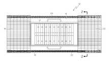
- FIG. 1is a top plan view of a convertible stadium that is constructed according to a preferred embodiment of the invention
- FIG. 2is a cross-sectional view of the convertible stadium depicted in FIG. 1 , shown in a closed position;
- FIG. 3is a cross-sectional view of the convertible stadium depicted in FIG. 1 , shown in an open position;
- FIG. 4is a fragmentary perspective view of a portion of the convertible stadium
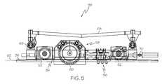
- FIG. 5is a cross-sectional view depicting a carrier unit according to the preferred embodiment
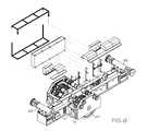
- FIG. 6is an exploded view depicting details of a carrier unit according to the preferred embodiment
- FIG. 7is a cross-sectional view depicting a rail clamp assembly according to the preferred embodiment.
- FIG. 8is a schematic diagram depicting a control system for the convertible stadium according to the preferred embodiment.
- FIG. 9is a schematic diagram depicting more details of the control system that is shown in FIG. 8 ;
- FIG. 10is a diagrammatical depiction of an anemometer constructed according to a preferred embodiment of the invention.
- a convertible stadium 10according to a preferred embodiment of the invention includes a playing field 12 which in the preferred embodiment is an American football field, and a seating area 14 for spectators.
- Convertible stadium 10is preferably what is generally considered to be a large stadium, i.e. a stadium that can accommodate over 40,000 spectators and that is suitable for professional sporting events such as National Football League games.
- Convertible stadium 10further preferably includes stationary roof structure 16 , a first movable roof panel 18 and a second movable roof panel 20 .
- the first and second movable roof panels 18 , 20are large, relatively heavy structures in engineering terms, having a length and a width of at least 100 feet in each dimension and a weight of at least 100 tons.
- both the first and second movable roof panels 18 , 20are constructed as a lenticular truss as taught in U.S. Pat. No. 4,789,360 to Silberman et al., the disclosure of which is incorporated by reference as if set forth fully herein.
- first and second movable roof panels 18 , 20are both movably mounted on the stationary roof structure 16 so as to be movable along a path between a first fully open position as is depicted in FIGS. 1 and 3 and a second fully closed position as is depicted in FIG. 2 , or in any of an infinite number of intermediate positions therebetween.
- convertible stadium 10In the fully open position, convertible stadium 10 is effectively an outdoor stadium, while in the fully closed position convertible stadium 10 is effectively an indoor stadium.
- the first and second movable roof panels 18 , 20are constructed and arranged to travel a distance of at least 50 feet between the fully open position and the fully closed position. In the preferred embodiment, the first and second movable roof panels 18 , 20 are constructed and arranged to travel a distance of approximately 182 feet between the fully open and fully closed positions.
- first and second movable roof panels 18 , 20are both mounted for movement along the path with respect to the stationary roof structure 16 by means of first and second parallel guide track assemblies 22 , 24 that are provided at opposite lateral sides of the top of the stationary roof structure 16 .
- first guide track assembly 22is supported by framework 26 that is part of the stationary roof structure 16 and that includes a plurality of struts 28 and tension rods 30 .
- the guide track assembly 22is supported and protected by a longitudinally extending box frame 32 .
- a longitudinally extending rail member 36is provided which, as is shown in FIG. 4 , is rigidly secured to an upper end of box frame 32 .
- rail member 36is inclined or curved so that the movable roof panels 18 , 20 are biased by gravity and their own weight toward the fully open position.
- rail member 36is convexly curved, and has a radius of curvature of at least 750 feet. In the most preferred embodiment, rail member 36 has a radius of curvature of approximately 1500 feet.
- the slope of the rail member 36preferably varies within a range of about 0° to about 45°, and is more preferably within range of about 0° to about 25°. Most preferably, the slope of the rail member 36 varies within a range of about 0° to about 15°.
- a carrier assembly 34is mounted to travel along the path on each rail member 36 .
- Carrier assembly 34includes a first carrier unit 38 , a second carrier unit 40 , a third carrier unit 42 and a fourth carrier unit 44 .
- a first linkage assembly 46 , a second linkage assembly 48 and a third linkage assembly 50are provided to securely link the carrier units 38 , 40 , 42 , 44 to each other.
- the carrier units 38 , 40 , 42 , 44are secured to the lenticular roof panel 64 via linkages including linear bearings 66 , 68 , as is best shown in FIG. 5 .
- carrier unit 38includes first and second rail follower wheels 50 , 52 that are configured to ride upon the rail 36 , a bumper assembly 54 , a rail clamp assembly 56 and a cable drum assembly 58 having a cable drum 60 for paying out and retracting a cable 62 in controlled fashion as will be described in greater detail below.
- a coupling 70is provided for coupling the carrier unit 38 to the linkage assembly 46 and to the other entrained carrier units 40 , 42 , 44 described above and that are depicted in FIG. 4 .
- each cable drum 60is provided with four drive motors 72 , 74 , 76 , 78 .
- Each cable drum 60will preferably drive one cable 62 , with one end of the cable 62 being anchored to the cable drum 60 and a second end of the cable drum 62 preferably being anchored to an anchor location 80 that is near the top of the maximum height of vertical travel of the respective movable roof panel 18 , 20 , near the parting line between the roof panels 18 , 20 when the roof panels 18 , 20 are in the closed position.
- the anchor location 80is best shown in FIGS. 2 and 3 .
- each drive motoris preferably equipped with fail-safe electric brakes that, when engaged, will prevent the operable roof panel 18 , 20 from moving under its own weight.
- An example of commercially available electric brakes that would be considered acceptable for this purposeis 45 ft-lb torque Kebco electric brakes.
- the expected maximum load on two cable and drum drive systems during operation or when holding the roof in placeis about 85 kips.
- the roofis preferably designed to be operational with up to one quarter of its motors failing, and to be stoppable with as many as nine out of 16 brakes failing.
- Each motor brakeis equipped with a brake switch, a mechanically activated switch that changes state according to the position of the brake discs. This switch is monitored by the central control system and is used to report any mechanical failure of the brake to operate.
- the brake torque value or its ability to hold and stop the loadis measured by briefly activating the motors against closed brakes and monitor the roof (via the absolute encoders mounted on each roof side) for any motion. Motion would indicate wear of the brake discs; the more motion or slip, the greater wear. This is used in the maintenance program to monitor brake wear and to signal a need for replacement.
- each powered carrier unit 38 , 40 , 42 , 44will be equipped with one operable rail clamp assembly 92 , which will engage after the movable roof panel 18 , 20 comes to a complete stop and will prevent unwanted movement of the roof panel 18 , 20 .
- a machine screw jack 94 driven by an electric motor 96will compress a stack 98 of seven 2009212, reduced thickness Belleville Springs stacked in a guide assembly.
- An inner guide tube 100 attached to the top plate 102will provide alignment for the spring stack 98 , and two hardened washers 104 , 106 (one on top and one on the bottom) will provide a durable contact point during spring compression in release.
- the springswill distribute their load through the operable rail clamp assembly 92 and cause the tongs 108 to clamp on to the railhead 110 .
- a spreader beam 112will actuate a proximity sensor 114 , which will in turn stop rail clamp movement.
- the friction connection between the operable rail clamp tongs 108 and the railhead 110will prevent the movable roof panel 18 , 20 from moving laterally, and will also provide some uplift load resistance.
- FIGS. 8 and 9schematically depict an electronic control system 84 that is provided in the preferred embodiment for monitoring and controlling movement of the first and second movable roof panels 18 , 20 .
- the electronic control systemis constructed and arranged to compare movement of the first and second cable drums in order to maintain alignment of the roof panel with respect to the stationary roof structure as the roof panel travels thereover.
- Each roof quadrantwill have eight variable frequency drives (VFD) V, each controlling the motor speed in the starting and stopping ramps for two motors.
- VFDvariable frequency drives
- a Variable Frequency Drivecaptures conventional AC current and converts it to DC current, then reconstructs the sine wave of the current back to a regulated AC sine form. This feature is very useful in the acceleration/deceleration phase.
- the VFDwill start at 0 Hz and ramp up to full running speed (60 Hz or above) following a linear ramp or an ‘S’-curve, thus protecting the structure from undue stress.
- Most 3-phase AC motorsare 4-pole motors.
- conventional 3-phase 4-pole motorsare utilized, primarily because they are extremely economical to purchase.
- a conventional 4-pole motor when powered with 60 Hertz currentalways turns at about 1750 RPM.
- the relationship of the 4-poles and the alternating current at 60 Hertzis fundamental, and the machine will always seek to run at 1750 RPM. At these low speeds it is required to inject a higher voltage to maintain the torque output, which is also a function of the micro-processor within the VFD.
- This micro-processorcan be adjusted to output frequency on a sliding scale.
- the micro-processoris programmed based on predetermined calculations regarding the maximum torque and inertia that collateral equipment can withstand. It is a function of the stiffness of the building structure, the weight of the retractable roof, and the stiffness of the collateral machinery. The point is that the VFD is adjustable, and that by calculation the most favorable acceleration and/or deceleration curve may be determined.
- VFD'sallows movement of the equipment to be commenced at a very slow speed, as well as to permit eventual acceleration of the equipment up to twice the normal speed of a standard 3-phase motor, thereby completing the cycle time at a much faster speed than a conventional arrangement.
- the VFD with the application of the Programmable Logic Controller (PLC)can also react to the wind in and around the stadium. If it is found that the wind is of an excessive speed the VFD may be prevented from accelerating past a slower speed, thus protecting all of the machinery.
- PLCProgrammable Logic Controller
- This application of both the VFD and the PLCallows the mechanism to complete the opening cycle most of the time in half the speed of a conventional machine, while still maintaining the capability to slow down to 60 Hertz where it has its optimal torque during high wind conditions to maintain safety. This arrangement is a significant improvement over conventional drives.
- VFDV 1 , V 2 in FIG. 9
- the Masterreceives a speed command from the central system and starts turning its cable drum while simultaneously feeding its own torque value as a command to the seven follower VFDs. If a motor or a VFD on the Master Drum should fail, the roof will stop and the Master duties are transferred automatically to one of the other drums, after which an operator can restart the move. If a single motor on a VFD fails, the VFD is reset on the fly to half capacity, so as not to overload the remaining motor.
- Each of the follower VFDswill maintain a motor torque equal to that of its lead, which will ensure that all cables in each quadrant share the roof load equally.
- Each movable roof panel 18 , 20will be equipped with its own programmable logic controller (PLC) 86 , 88 that will work with the VFDs in that roof panel and control roof operation.
- PLCprogrammable logic controller
- Each cable drum 60will have an incremental encoder E I that will measure speed and direction of movement, as well as the incremental length of cable.
- Each roof quadrantwill have an absolute encoder E A located on the lead carrier, which will track the respective roof panel's position on the rail, and will remember the position when the roof is powered down and back up again.
- Control system 84will also preferably have a central controller 90 with an operator interface and that is in two way communication with each of the PLCs 86 , 88 .
- the PLC's 86 , 88control practically every aspect of operation of the opening and closing of the roof panels 18 , 20 , including operation of the rail clamps 96 , the motors, the brakes and the monitoring of operating conditions.
- a sensor 126is provided for enabling the PLC 86 to determine when the roof panel 18 , 20 has reached the fully closed position, and a second sensor 128 is provided for enabling the PLC 86 to determine when the roof panel 18 , 20 has reached the fully open position.
- Warning sirens and lights 122are provided that are actuatable by the PLC to warn humans of dangerous or irregular conditions.
- the PLCcoupled to the VFD, is the ability for the operator to continuously monitor the motor voltage, the motor frequency, and the motor output torque.
- the motor thermostat T M for each motoris also in data communication with the PLC. This may permit estimation of the dynamic tension in each of the cables during operation.
- These figuresare displayed on the operator's information screen and recorded continuously for historic reference and troubleshooting. These diagnostic features allow the operator confidence that the mechanism is functioning as intended and offer an early warning as soon as an inconsistency develops in the mechanism long before a serious failure would occur.
- the historical data loggingis programmed to download through the internet on a high-speed communications link to a remote facility, thus enabling engineers at that facility to monitor all systems in the field to be sure they are working properly.
- the combination of these devicesallows an unsophisticated owner with no engineering staff to operate highly technical equipment that heretofore could not be operated without a staff of engineers on-site, thereby significantly reducing the cost of ownership.
- Each of the two sides of a stadium roof panel 18 , 20will preferably have its own local Emergency Stop (E-Stop) circuit 124 to cut off power to the drive systems and reset the motor brakes in case of an E-Stop condition.
- E-StopEmergency Stop
- the control systems on the two roof sidesare galvanically isolated from each other by a fiber-optic cable connecting the two data LANs. This is done for two reasons:
- An E-Stop systemconsists of two redundant channels so that each E-Stop button has two contacts in the safety system. These channels are constantly monitored by a safety controller and a failure of either channel will result in an E-Stop condition. These two channels are carried between the two independent E-Stop systems as dual emitter-receiver fiber systems. If an E-Stop system is OK, it sends two independent light signals (different frequencies) through a single fiber to a pair of receivers on the other roof side. The two receivers each have an output contact which is part of the local E-Stop system. An identical, but opposite system, makes the second side part of the first side's E-Stop system.
- the installed roofwill have an emergency stop system that will bypass the PLC's and VFDs and when activated, will disconnect all power to the motors and brakes, causing the failsafe, spring-set brakes to engage and stop the movable roof panel 18 , 20 from moving.
- Each quadrantwill have one overspeed sensing system S O independent of the control system 84 that will stop the roof panel 18 , 20 if it moves over the allowed speed.
- a disk with magnets embedded in the outer edgewill be driven by a carrier wheel and will generate a pulse train as a drives past the sensor. If the pulse train goes above the allowed speed, power to the motors and brakes will be cut, causing the failsafe electric brakes to engage.
- the overspeed sensing system S Ois independent of the control system 84 it still reports data to the responsible PLC for the particular roof panel 18 , 20 to which it is attached.
- the stadium roofis preferably equipped with an anemometer 120 to monitor the wind speed and to prevent roof motion when the wind speed exceeds the design values.
- an anemometer 120Given the nature of the anemometer 120 it is generally mounted on to a very tall structure and as such is exposed to lightning strikes or, even in the absence of actual lightning strikes, to elevated electrostatic surges, which can destroy sensitive electronic circuits in modern anemometers. To eliminate this risk, an anemometer was designed which is entirely based on fiber-optic signals. An emitter/receiver pair is located below the roof line and the connected fiber-optic cable 132 runs up the anemometer mast to a pair of lenses separated by a small air gap.
- a mechanical “flag” 134mounted on the shaft 136 that also holds the three anemometer cups 138 that are driven by the wind.
- the flag 134interrupts the light beam every time the anemometer rotates one revolution.
- the receiver below the roof line (and out of harms way)sends the resulting electrical pulses to a counter which is part of the central control system 90 .
Landscapes
- Engineering & Computer Science (AREA)
- Architecture (AREA)
- Physics & Mathematics (AREA)
- Electromagnetism (AREA)
- Civil Engineering (AREA)
- Structural Engineering (AREA)
- Buildings Adapted To Withstand Abnormal External Influences (AREA)
Abstract
Description
Claims (33)
Priority Applications (1)
| Application Number | Priority Date | Filing Date | Title |
|---|---|---|---|
| US11/367,563US8186107B2 (en) | 2005-03-09 | 2006-03-03 | Cable drive and control system for movable stadium roof panels |
Applications Claiming Priority (2)
| Application Number | Priority Date | Filing Date | Title |
|---|---|---|---|
| US65979205P | 2005-03-09 | 2005-03-09 | |
| US11/367,563US8186107B2 (en) | 2005-03-09 | 2006-03-03 | Cable drive and control system for movable stadium roof panels |
Publications (2)
| Publication Number | Publication Date |
|---|---|
| US20070017163A1 US20070017163A1 (en) | 2007-01-25 |
| US8186107B2true US8186107B2 (en) | 2012-05-29 |
Family
ID=37677781
Family Applications (1)
| Application Number | Title | Priority Date | Filing Date |
|---|---|---|---|
| US11/367,563Expired - Fee RelatedUS8186107B2 (en) | 2005-03-09 | 2006-03-03 | Cable drive and control system for movable stadium roof panels |
Country Status (1)
| Country | Link |
|---|---|
| US (1) | US8186107B2 (en) |
Cited By (5)
| Publication number | Priority date | Publication date | Assignee | Title |
|---|---|---|---|---|
| US20110107688A1 (en)* | 2008-07-14 | 2011-05-12 | Francois Delaney | Self-supporting pier for a retractable roof system for a large building structure |
| US20120204497A1 (en)* | 2011-02-16 | 2012-08-16 | Advanced Technical Solutions Gmbh | Airstream deflection system for outdoor areas |
| US20150375074A1 (en)* | 2013-02-07 | 2015-12-31 | Atlantic Recreation, Inc. | System and method for retractable tennis court shade device |
| US11434634B2 (en)* | 2018-12-11 | 2022-09-06 | Morgan Engineering Systems, Inc. | Method and apparatus for supporting and moving a long-span structure on a rail system |
| US12276430B2 (en) | 2023-09-05 | 2025-04-15 | Schwab-Vollhaber-Lubratt, Inc. | HVAC equipment screening systems |
Families Citing this family (7)
| Publication number | Priority date | Publication date | Assignee | Title |
|---|---|---|---|---|
| US8186107B2 (en)* | 2005-03-09 | 2012-05-29 | Uni-Systems, Llc | Cable drive and control system for movable stadium roof panels |
| US8202047B2 (en)* | 2007-06-07 | 2012-06-19 | Hewlett-Packard Development Company, L.P. | Fan module latching device |
| WO2011088113A1 (en)* | 2010-01-12 | 2011-07-21 | Cabreeco Companies Llc | Movable enclosure |
| US8950308B2 (en)* | 2011-03-23 | 2015-02-10 | Advanced Materials And Devices, Inc. | Forward closure system |
| US8505246B1 (en) | 2011-10-06 | 2013-08-13 | Cadorath Leisure Products Ltd. | Screen room with pivoting roof panels |
| DE102016201816B4 (en)* | 2016-02-05 | 2022-01-13 | Delta-X Gmbh Ingenieurgesellschaft | Device for locking a retractable roof |
| CN112095882A (en)* | 2020-08-28 | 2020-12-18 | 中冶(上海)钢结构科技有限公司 | Folding roof structure adopting overhanging structure and folding method |
Citations (92)
| Publication number | Priority date | Publication date | Assignee | Title |
|---|---|---|---|---|
| US1559261A (en)* | 1925-08-07 | 1925-10-27 | Arthur R Konsalik | Skylight |
| US2052217A (en) | 1933-06-20 | 1936-08-25 | Sibour Jules H De | All weather stadium |
| US2603171A (en) | 1947-03-26 | 1952-07-15 | H W Martin | Building structure |
| US2642162A (en) | 1948-05-24 | 1953-06-16 | Herrmann B Tobias | Collapsible metal shelter |
| US2921592A (en)* | 1957-07-10 | 1960-01-19 | Cid Air Structures Company | Support for air-inflated building structure |
| US3009211A (en) | 1959-04-20 | 1961-11-21 | Leo R Hansen | Building structure |
| US3135296A (en)* | 1960-10-12 | 1964-06-02 | Flexonics Corp | Laminated tubing |
| US3213571A (en) | 1961-08-08 | 1965-10-26 | Irvin E Olson | Observatory dome |
| US3261133A (en)* | 1963-02-05 | 1966-07-19 | Happich Gmbh Gebr | Sliding roof arrangement |
| US3266328A (en)* | 1962-06-09 | 1966-08-16 | H T Golde G M B H & Co Kg | Driving device for a sliding roof |
| US3277619A (en)* | 1963-08-13 | 1966-10-11 | David S Miller | Movable roof device |
| US3288158A (en) | 1963-05-31 | 1966-11-29 | Gugliotta Paul | Movable roof structure |
| US3436132A (en)* | 1966-05-02 | 1969-04-01 | Teledyne Inc | Slide assembly |
| US3465483A (en)* | 1968-01-19 | 1969-09-09 | Rollamatic Roofs Inc | Movable roof |
| US3534511A (en) | 1968-04-08 | 1970-10-20 | Michael Cappella | Retractable cover for outdoor areas |
| US3579932A (en)* | 1969-04-28 | 1971-05-25 | Ross T Atkinson | Cable-suspended roof structure |
| US3608252A (en) | 1969-11-05 | 1971-09-28 | Joseph R Bisson | Combination hatchway-hothouse |
| US3766691A (en) | 1971-12-02 | 1973-10-23 | G Ray | Convertible pool enclosure |
| US4175361A (en) | 1977-10-13 | 1979-11-27 | Kiyomitsu Tanaka | Openable canopy housing |
| US4177973A (en)* | 1978-03-06 | 1979-12-11 | Ederer Incorporated | Cable drum safety brake |
| US4257199A (en) | 1979-05-31 | 1981-03-24 | Kazuo Kuboyama | Stadium cover |
| NL8006712A (en) | 1980-12-10 | 1982-07-01 | Gerrit Jan Dollen | Enclosure for e.g. sports hall - has portal sections telescopically movable on rails to two ends from transverse mid plane |
| US4347993A (en)* | 1979-11-06 | 1982-09-07 | W. J. Industries, Incorporated | Tension monitor means and system |
| US4348833A (en) | 1981-02-18 | 1982-09-14 | Seiwa Kagaku Kabushiki Kaisha | Opening and closing a flexible screen in a greenhouse or the like |
| US4515416A (en)* | 1983-05-13 | 1985-05-07 | Hiroshi Teramachi | Linear slide bearing |
| US4569164A (en)* | 1983-04-08 | 1986-02-11 | Advanced Equipment Corp. | Operable wall system |
| US4581860A (en)* | 1985-06-20 | 1986-04-15 | Berger Horst L | Saddle-shaped cable dome system for large span lightweight roof structures |
| US4587775A (en) | 1984-07-18 | 1986-05-13 | Earl & Wright | Retractable closure for roof opening |
| US4616451A (en) | 1985-06-03 | 1986-10-14 | Glick Sidney E | Telescoping roof structure |
| US4636962A (en)* | 1983-05-24 | 1987-01-13 | Columbus Mckinnon Corporation | Microprocessor-controlled hoist system |
| US4676033A (en) | 1986-05-01 | 1987-06-30 | Allen Christopher M | Stadium building |
| US4682449A (en)* | 1986-09-30 | 1987-07-28 | Berger Horst L | Retractable stadium roof system with rectangular opening |
| US4706419A (en) | 1985-04-09 | 1987-11-17 | Ohbayashi-Gumi, Ltd. | Openable dome-shaped roof structure |
| US4716691A (en) | 1986-05-01 | 1988-01-05 | Allen Christopher M | Stadium building |
| US4727688A (en)* | 1986-04-08 | 1988-03-01 | Ohbayashi-Gumi, Ltd. | Retractable roof structure |
| US4738057A (en) | 1986-04-14 | 1988-04-19 | Logan Kenneth C | Arch supported retractable inflatable roof |
| US4751800A (en) | 1985-01-23 | 1988-06-21 | Ohbayashi-Gumi, Ltd. | Openable dome-shaped roof structure |
| US4802314A (en) | 1987-11-24 | 1989-02-07 | Schildge Jr Adam T | Cable-stay roof for stadium or arena and method of construction of same |
| US4804095A (en)* | 1985-10-12 | 1989-02-14 | Rohr Gmbh | Cutoff device for crane systems |
| US4831792A (en)* | 1986-09-30 | 1989-05-23 | Berger Horst L | Retractable stadium roof system with rectangular opening |
| US4833837A (en) | 1986-02-07 | 1989-05-30 | Societe D'etudes Techniques Et D'entreprises Generales Sodeteg | Folding radome |
| US4920707A (en) | 1988-10-07 | 1990-05-01 | Wiktor Moskaliuk | Interior canopy for stadium |
| US4936060A (en) | 1988-10-14 | 1990-06-26 | J. W. Welsh & Associates, Inc. | Flexible roof control system |
| US4942698A (en) | 1988-11-22 | 1990-07-24 | Shimizu Construction Co., Ltd. | Openable roof and structure therewith |
| JPH02217539A (en) | 1989-02-20 | 1990-08-30 | Fujita Corp | retractable dome roof |
| JPH02269237A (en) | 1989-04-10 | 1990-11-02 | Ohbayashi Corp | Opening/closing type roof |
| US4995203A (en)* | 1990-02-02 | 1991-02-26 | Stadium Consultants International Inc. | Retractable roof for stadium structure |
| US5007214A (en) | 1989-04-10 | 1991-04-16 | Ohbayashi Corporation | Openable dome-shaped roof structure |
| US5010695A (en) | 1990-01-10 | 1991-04-30 | Schildge Jr Adam T | Cable-stay roof for stadium or arena and method of construction of same |
| JPH03115632A (en) | 1989-09-28 | 1991-05-16 | Ohbayashi Corp | Openable roof |
| US5027565A (en) | 1989-08-16 | 1991-07-02 | Shimizu Construction Co., Ltd. | Openable roof |
| US5035093A (en) | 1990-03-05 | 1991-07-30 | Blenkhorn And Sawle Limited | Building structure with fixed center and movable perimeter roof sections |
| US5058332A (en) | 1989-02-09 | 1991-10-22 | Tobishima Corporation | Domed structures having retractable roofs |
| US5062243A (en) | 1988-11-24 | 1991-11-05 | Shimizu Construction Co., Ltd. | Openable roof |
| US5063730A (en)* | 1989-03-30 | 1991-11-12 | Mitsubishi Jukogyo Kabushiki Kaisha | Openable roof apparatus |
| US5070659A (en)* | 1990-02-02 | 1991-12-10 | Stadium Consultants International, Inc. | Retractable roof for stadium structure |
| US5103600A (en) | 1989-05-31 | 1992-04-14 | Geiger David H | Multi-purpose stadium |
| US5115127A (en)* | 1990-01-03 | 1992-05-19 | The United States Of America As Represented By The Secretary Of The Navy | Optical fiber sensor for measuring physical properties of fluids |
| US5117594A (en) | 1989-03-30 | 1992-06-02 | Mitsubishi Jukogyo Kabushiki Kaisha Shimizu Construction Co. | Openable roof apparatus |
| JPH04323446A (en) | 1991-02-14 | 1992-11-12 | Zenitakagumi:Kk | retractable roof |
| US5167097A (en) | 1989-01-31 | 1992-12-01 | Robbie Roderick G | Retractable stadium roof |
| US5187894A (en) | 1990-10-09 | 1993-02-23 | The Greenway Services, Inc. | Turfing systems for stadia |
| US5189851A (en)* | 1989-01-24 | 1993-03-02 | Kajima Corporation | Movable dome-type roof for structure |
| US5203125A (en) | 1989-08-16 | 1993-04-20 | Shimizu Construction Co., Ltd. | Openable roof |
| US5257481A (en) | 1989-01-25 | 1993-11-02 | George S. Reppas | Retractable dome |
| US5257485A (en) | 1991-02-22 | 1993-11-02 | Mamoru Kawaguchi | Openable and closeable roof construction |
| US5355641A (en)* | 1990-11-02 | 1994-10-18 | Weidlinger Associates, Inc. | Triangulated cable dome with retractable roof |
| US5371983A (en) | 1992-04-08 | 1994-12-13 | Mamoru Kawaguchi And Maeda Corporation | Dome shaped roof structure |
| US5394660A (en) | 1993-12-02 | 1995-03-07 | Haris; Ali A. K. | Segmented retractable steel roofs |
| US5522192A (en)* | 1993-08-16 | 1996-06-04 | Frantl; Erich | Hangar |
| US5622013A (en)* | 1994-03-07 | 1997-04-22 | Kajima Corporation | Structure of multipurpose suspended roof arena capable of changing space volume and construction method thereof |
| US5653066A (en) | 1995-10-17 | 1997-08-05 | Schildge, Jr.; Adam T. | Cable-stay retractable skylight roof for stadium or arena or other structure and method of construction of same |
| US5682711A (en) | 1996-04-25 | 1997-11-04 | Warczak; Russell C. | Game field |
| US5746028A (en) | 1997-06-26 | 1998-05-05 | Dibenedetto; John | Moveable grass field |
| US5778603A (en) | 1996-10-29 | 1998-07-14 | Reppas; George S. | Retractable dome |
| US5857294A (en)* | 1994-08-05 | 1999-01-12 | Castro; Gerardo | Dome roof structure and method of designing and constructing same |
| US5875281A (en)* | 1997-07-24 | 1999-02-23 | Cableform, Inc. | DC solid state series wound motor drive |
| US5896708A (en) | 1996-12-02 | 1999-04-27 | Mitsubishi Heavy Industries, Ltd. | Movable support for a retractable roof |
| US5904003A (en)* | 1998-04-09 | 1999-05-18 | Stephen; John W. | Retractable stadium cover |
| US5927022A (en) | 1996-08-09 | 1999-07-27 | Kawasaki Jukogyo Kabushiki | Multipurpose field moving method and apparatus |
| US6003269A (en)* | 1997-04-07 | 1999-12-21 | Mcree; Richard T. | Retractable covering for spaces |
| US6082054A (en)* | 1998-08-27 | 2000-07-04 | Silberman; Cyril J. | Retractable stadium roofs and transport mechanism therefor |
| US6145254A (en)* | 1998-11-05 | 2000-11-14 | Silva; Maria Leticia | Retractable roof panel |
| US6385912B1 (en)* | 1997-12-18 | 2002-05-14 | Schiess-Defries Engineering Immobilien-Und Bautrager Gmbh | Construction substructure |
| US6415556B1 (en)* | 2000-07-03 | 2002-07-09 | Uni-Systems, Inc. | Transport mechanism for large structures such as retractable stadium rooves |
| US20020129565A1 (en)* | 2001-01-23 | 2002-09-19 | Cyril Silberman | Retractable roof system for stadium |
| US6698141B2 (en)* | 2001-01-23 | 2004-03-02 | Uni-Systems, Llc | Convertible stadium and method of operating |
| US6718696B2 (en)* | 2001-01-23 | 2004-04-13 | Uni-Systems, Llc | Movable wall for stadium |
| US6754994B2 (en)* | 2000-03-01 | 2004-06-29 | Farahmand Jahanpour | Retractable roof |
| US6768321B2 (en)* | 2002-01-16 | 2004-07-27 | Ctex Seat Comfort Limited | Component position indicating apparatus |
| US6851227B1 (en)* | 2001-06-05 | 2005-02-08 | Adam T. Schildge, Jr. | Retractable roof for a mall or other space |
| US20070017163A1 (en)* | 2005-03-09 | 2007-01-25 | Cyril Silberman | Cable drive and control system for movable stadium roof panels |
- 2006
- 2006-03-03USUS11/367,563patent/US8186107B2/ennot_activeExpired - Fee Related
Patent Citations (97)
| Publication number | Priority date | Publication date | Assignee | Title |
|---|---|---|---|---|
| US1559261A (en)* | 1925-08-07 | 1925-10-27 | Arthur R Konsalik | Skylight |
| US2052217A (en) | 1933-06-20 | 1936-08-25 | Sibour Jules H De | All weather stadium |
| US2603171A (en) | 1947-03-26 | 1952-07-15 | H W Martin | Building structure |
| US2642162A (en) | 1948-05-24 | 1953-06-16 | Herrmann B Tobias | Collapsible metal shelter |
| US2921592A (en)* | 1957-07-10 | 1960-01-19 | Cid Air Structures Company | Support for air-inflated building structure |
| US3009211A (en) | 1959-04-20 | 1961-11-21 | Leo R Hansen | Building structure |
| US3135296A (en)* | 1960-10-12 | 1964-06-02 | Flexonics Corp | Laminated tubing |
| US3213571A (en) | 1961-08-08 | 1965-10-26 | Irvin E Olson | Observatory dome |
| US3266328A (en)* | 1962-06-09 | 1966-08-16 | H T Golde G M B H & Co Kg | Driving device for a sliding roof |
| US3261133A (en)* | 1963-02-05 | 1966-07-19 | Happich Gmbh Gebr | Sliding roof arrangement |
| US3288158A (en) | 1963-05-31 | 1966-11-29 | Gugliotta Paul | Movable roof structure |
| US3277619A (en)* | 1963-08-13 | 1966-10-11 | David S Miller | Movable roof device |
| US3436132A (en)* | 1966-05-02 | 1969-04-01 | Teledyne Inc | Slide assembly |
| US3465483A (en)* | 1968-01-19 | 1969-09-09 | Rollamatic Roofs Inc | Movable roof |
| US3534511A (en) | 1968-04-08 | 1970-10-20 | Michael Cappella | Retractable cover for outdoor areas |
| US3579932A (en)* | 1969-04-28 | 1971-05-25 | Ross T Atkinson | Cable-suspended roof structure |
| US3608252A (en) | 1969-11-05 | 1971-09-28 | Joseph R Bisson | Combination hatchway-hothouse |
| US3766691A (en) | 1971-12-02 | 1973-10-23 | G Ray | Convertible pool enclosure |
| US4175361A (en) | 1977-10-13 | 1979-11-27 | Kiyomitsu Tanaka | Openable canopy housing |
| US4177973A (en)* | 1978-03-06 | 1979-12-11 | Ederer Incorporated | Cable drum safety brake |
| US4257199A (en) | 1979-05-31 | 1981-03-24 | Kazuo Kuboyama | Stadium cover |
| US4347993A (en)* | 1979-11-06 | 1982-09-07 | W. J. Industries, Incorporated | Tension monitor means and system |
| NL8006712A (en) | 1980-12-10 | 1982-07-01 | Gerrit Jan Dollen | Enclosure for e.g. sports hall - has portal sections telescopically movable on rails to two ends from transverse mid plane |
| US4348833A (en) | 1981-02-18 | 1982-09-14 | Seiwa Kagaku Kabushiki Kaisha | Opening and closing a flexible screen in a greenhouse or the like |
| US4569164A (en)* | 1983-04-08 | 1986-02-11 | Advanced Equipment Corp. | Operable wall system |
| US4515416A (en)* | 1983-05-13 | 1985-05-07 | Hiroshi Teramachi | Linear slide bearing |
| US4636962A (en)* | 1983-05-24 | 1987-01-13 | Columbus Mckinnon Corporation | Microprocessor-controlled hoist system |
| US4587775A (en) | 1984-07-18 | 1986-05-13 | Earl & Wright | Retractable closure for roof opening |
| US4751800A (en) | 1985-01-23 | 1988-06-21 | Ohbayashi-Gumi, Ltd. | Openable dome-shaped roof structure |
| US4706419A (en) | 1985-04-09 | 1987-11-17 | Ohbayashi-Gumi, Ltd. | Openable dome-shaped roof structure |
| US4616451A (en) | 1985-06-03 | 1986-10-14 | Glick Sidney E | Telescoping roof structure |
| US4581860A (en)* | 1985-06-20 | 1986-04-15 | Berger Horst L | Saddle-shaped cable dome system for large span lightweight roof structures |
| US4804095A (en)* | 1985-10-12 | 1989-02-14 | Rohr Gmbh | Cutoff device for crane systems |
| US4833837A (en) | 1986-02-07 | 1989-05-30 | Societe D'etudes Techniques Et D'entreprises Generales Sodeteg | Folding radome |
| US4727688A (en)* | 1986-04-08 | 1988-03-01 | Ohbayashi-Gumi, Ltd. | Retractable roof structure |
| US4738057A (en) | 1986-04-14 | 1988-04-19 | Logan Kenneth C | Arch supported retractable inflatable roof |
| US4716691A (en) | 1986-05-01 | 1988-01-05 | Allen Christopher M | Stadium building |
| US4676033A (en) | 1986-05-01 | 1987-06-30 | Allen Christopher M | Stadium building |
| US4682449A (en)* | 1986-09-30 | 1987-07-28 | Berger Horst L | Retractable stadium roof system with rectangular opening |
| US4831792A (en)* | 1986-09-30 | 1989-05-23 | Berger Horst L | Retractable stadium roof system with rectangular opening |
| US4802314A (en) | 1987-11-24 | 1989-02-07 | Schildge Jr Adam T | Cable-stay roof for stadium or arena and method of construction of same |
| US4920707A (en) | 1988-10-07 | 1990-05-01 | Wiktor Moskaliuk | Interior canopy for stadium |
| US4936060A (en) | 1988-10-14 | 1990-06-26 | J. W. Welsh & Associates, Inc. | Flexible roof control system |
| US4942698A (en) | 1988-11-22 | 1990-07-24 | Shimizu Construction Co., Ltd. | Openable roof and structure therewith |
| US5062243A (en) | 1988-11-24 | 1991-11-05 | Shimizu Construction Co., Ltd. | Openable roof |
| US5189851A (en)* | 1989-01-24 | 1993-03-02 | Kajima Corporation | Movable dome-type roof for structure |
| US5257481A (en) | 1989-01-25 | 1993-11-02 | George S. Reppas | Retractable dome |
| US5167097A (en) | 1989-01-31 | 1992-12-01 | Robbie Roderick G | Retractable stadium roof |
| US5058332A (en) | 1989-02-09 | 1991-10-22 | Tobishima Corporation | Domed structures having retractable roofs |
| JPH02217539A (en) | 1989-02-20 | 1990-08-30 | Fujita Corp | retractable dome roof |
| US5117594A (en) | 1989-03-30 | 1992-06-02 | Mitsubishi Jukogyo Kabushiki Kaisha Shimizu Construction Co. | Openable roof apparatus |
| US5063730A (en)* | 1989-03-30 | 1991-11-12 | Mitsubishi Jukogyo Kabushiki Kaisha | Openable roof apparatus |
| US5007214A (en) | 1989-04-10 | 1991-04-16 | Ohbayashi Corporation | Openable dome-shaped roof structure |
| JPH02269237A (en) | 1989-04-10 | 1990-11-02 | Ohbayashi Corp | Opening/closing type roof |
| US5103600A (en) | 1989-05-31 | 1992-04-14 | Geiger David H | Multi-purpose stadium |
| US5203125A (en) | 1989-08-16 | 1993-04-20 | Shimizu Construction Co., Ltd. | Openable roof |
| US5027565A (en) | 1989-08-16 | 1991-07-02 | Shimizu Construction Co., Ltd. | Openable roof |
| JPH03115632A (en) | 1989-09-28 | 1991-05-16 | Ohbayashi Corp | Openable roof |
| US5115127A (en)* | 1990-01-03 | 1992-05-19 | The United States Of America As Represented By The Secretary Of The Navy | Optical fiber sensor for measuring physical properties of fluids |
| US5010695A (en) | 1990-01-10 | 1991-04-30 | Schildge Jr Adam T | Cable-stay roof for stadium or arena and method of construction of same |
| US4995203A (en)* | 1990-02-02 | 1991-02-26 | Stadium Consultants International Inc. | Retractable roof for stadium structure |
| US5070659A (en)* | 1990-02-02 | 1991-12-10 | Stadium Consultants International, Inc. | Retractable roof for stadium structure |
| US5035093A (en) | 1990-03-05 | 1991-07-30 | Blenkhorn And Sawle Limited | Building structure with fixed center and movable perimeter roof sections |
| US5187894A (en) | 1990-10-09 | 1993-02-23 | The Greenway Services, Inc. | Turfing systems for stadia |
| US5355641A (en)* | 1990-11-02 | 1994-10-18 | Weidlinger Associates, Inc. | Triangulated cable dome with retractable roof |
| JPH04323446A (en) | 1991-02-14 | 1992-11-12 | Zenitakagumi:Kk | retractable roof |
| US5257485A (en) | 1991-02-22 | 1993-11-02 | Mamoru Kawaguchi | Openable and closeable roof construction |
| US5394659A (en)* | 1991-02-22 | 1995-03-07 | Mamoru Kawaguchi | Openable and closeable roof construction |
| US5371983A (en) | 1992-04-08 | 1994-12-13 | Mamoru Kawaguchi And Maeda Corporation | Dome shaped roof structure |
| US5522192A (en)* | 1993-08-16 | 1996-06-04 | Frantl; Erich | Hangar |
| US5394660A (en) | 1993-12-02 | 1995-03-07 | Haris; Ali A. K. | Segmented retractable steel roofs |
| US5622013A (en)* | 1994-03-07 | 1997-04-22 | Kajima Corporation | Structure of multipurpose suspended roof arena capable of changing space volume and construction method thereof |
| US5857294A (en)* | 1994-08-05 | 1999-01-12 | Castro; Gerardo | Dome roof structure and method of designing and constructing same |
| US5848499A (en)* | 1995-10-17 | 1998-12-15 | Schildge, Jr.; Adam T. | Cable-stay retractable skylight roof for stadium or arena or other structure and method of construction of same |
| US5653066A (en) | 1995-10-17 | 1997-08-05 | Schildge, Jr.; Adam T. | Cable-stay retractable skylight roof for stadium or arena or other structure and method of construction of same |
| US5682711A (en) | 1996-04-25 | 1997-11-04 | Warczak; Russell C. | Game field |
| US5927022A (en) | 1996-08-09 | 1999-07-27 | Kawasaki Jukogyo Kabushiki | Multipurpose field moving method and apparatus |
| US5778603A (en) | 1996-10-29 | 1998-07-14 | Reppas; George S. | Retractable dome |
| US5983575A (en)* | 1996-10-29 | 1999-11-16 | Reppas; George S. | Retractable dome |
| US5896708A (en) | 1996-12-02 | 1999-04-27 | Mitsubishi Heavy Industries, Ltd. | Movable support for a retractable roof |
| US6003269A (en)* | 1997-04-07 | 1999-12-21 | Mcree; Richard T. | Retractable covering for spaces |
| US5746028A (en) | 1997-06-26 | 1998-05-05 | Dibenedetto; John | Moveable grass field |
| US5875281A (en)* | 1997-07-24 | 1999-02-23 | Cableform, Inc. | DC solid state series wound motor drive |
| US6385912B1 (en)* | 1997-12-18 | 2002-05-14 | Schiess-Defries Engineering Immobilien-Und Bautrager Gmbh | Construction substructure |
| US5904003A (en)* | 1998-04-09 | 1999-05-18 | Stephen; John W. | Retractable stadium cover |
| US6082054A (en)* | 1998-08-27 | 2000-07-04 | Silberman; Cyril J. | Retractable stadium roofs and transport mechanism therefor |
| US6367206B1 (en)* | 1998-08-27 | 2002-04-09 | Uni-Systems, Inc. | Retractable stadium roofs and transport mechanism therefor |
| US6145254A (en)* | 1998-11-05 | 2000-11-14 | Silva; Maria Leticia | Retractable roof panel |
| US6754994B2 (en)* | 2000-03-01 | 2004-06-29 | Farahmand Jahanpour | Retractable roof |
| US6415556B1 (en)* | 2000-07-03 | 2002-07-09 | Uni-Systems, Inc. | Transport mechanism for large structures such as retractable stadium rooves |
| US20020129565A1 (en)* | 2001-01-23 | 2002-09-19 | Cyril Silberman | Retractable roof system for stadium |
| US6698141B2 (en)* | 2001-01-23 | 2004-03-02 | Uni-Systems, Llc | Convertible stadium and method of operating |
| US6718696B2 (en)* | 2001-01-23 | 2004-04-13 | Uni-Systems, Llc | Movable wall for stadium |
| US6789360B2 (en)* | 2001-01-23 | 2004-09-14 | Uni-Systems, Llc | Retractable roof system for stadium |
| US6851227B1 (en)* | 2001-06-05 | 2005-02-08 | Adam T. Schildge, Jr. | Retractable roof for a mall or other space |
| US6768321B2 (en)* | 2002-01-16 | 2004-07-27 | Ctex Seat Comfort Limited | Component position indicating apparatus |
| US20070017163A1 (en)* | 2005-03-09 | 2007-01-25 | Cyril Silberman | Cable drive and control system for movable stadium roof panels |
Cited By (6)
| Publication number | Priority date | Publication date | Assignee | Title |
|---|---|---|---|---|
| US20110107688A1 (en)* | 2008-07-14 | 2011-05-12 | Francois Delaney | Self-supporting pier for a retractable roof system for a large building structure |
| US9976302B2 (en)* | 2008-07-14 | 2018-05-22 | François Delaney | Self-supporting pier for a retractable roof system for a large building structure |
| US20120204497A1 (en)* | 2011-02-16 | 2012-08-16 | Advanced Technical Solutions Gmbh | Airstream deflection system for outdoor areas |
| US20150375074A1 (en)* | 2013-02-07 | 2015-12-31 | Atlantic Recreation, Inc. | System and method for retractable tennis court shade device |
| US11434634B2 (en)* | 2018-12-11 | 2022-09-06 | Morgan Engineering Systems, Inc. | Method and apparatus for supporting and moving a long-span structure on a rail system |
| US12276430B2 (en) | 2023-09-05 | 2025-04-15 | Schwab-Vollhaber-Lubratt, Inc. | HVAC equipment screening systems |
Also Published As
| Publication number | Publication date |
|---|---|
| US20070017163A1 (en) | 2007-01-25 |
Similar Documents
| Publication | Publication Date | Title |
|---|---|---|
| US8186107B2 (en) | Cable drive and control system for movable stadium roof panels | |
| US6789360B2 (en) | Retractable roof system for stadium | |
| US4342539A (en) | Retractable wind machine | |
| US7818920B2 (en) | Barrier gate with torque limiter | |
| RU2396998C2 (en) | Preventer | |
| EP1879780B1 (en) | Platform door system | |
| AU659987B2 (en) | Power mine door system | |
| CN104727725B (en) | Driving for overhead door and control system | |
| CN106938619A (en) | Cargo handling sidesway contact net system | |
| US6698141B2 (en) | Convertible stadium and method of operating | |
| CN102343913A (en) | Cable car assembly and method for its operation | |
| CN109944451A (en) | Across both wired construction safety protection device and its construction method in one kind | |
| US8636265B1 (en) | Winch for raising and lowering theater scenery | |
| CN103818797A (en) | Speed limiter and safety gear linkage system based on elevator | |
| US6367206B1 (en) | Retractable stadium roofs and transport mechanism therefor | |
| US4736641A (en) | Self-supporting, trackless, rectilinear load transporter | |
| CN102963699B (en) | Operation control method and control system of multi-drive chain conveying line | |
| CZ305310B6 (en) | Method of controlling and checking mechanical caution of light level crossing warning systems employing electromechanical drive of barrier and apparatus for making the same | |
| CN111071900A (en) | Elevator without pit | |
| CN216251945U (en) | Novel assembled strideing across equipment | |
| WO1995022502A1 (en) | Security and monitoring system of a working platform system | |
| CN201517470U (en) | Automatic speed regulation mechanism of a vertical axle type wind driven generator | |
| JP4795751B2 (en) | Branch line type ground collapse prediction device | |
| CN211920561U (en) | Elevator without pit | |
| KR102865864B1 (en) | Automated control play swing apparatus with curved lifting assembly |
Legal Events
| Date | Code | Title | Description |
|---|---|---|---|
| AS | Assignment | Owner name:UNI-SYSTEMS, LLC, MINNESOTA Free format text:ASSIGNMENT OF ASSIGNORS INTEREST;ASSIGNORS:SILBERMAN, MR. CYRIL J;RIBERICH, MR. BARTON L.;NIELSEN, MR. LENNART;AND OTHERS;REEL/FRAME:017722/0483 Effective date:20060425 Owner name:UNI-SYSTEMS, LLC, MINNESOTA Free format text:ASSIGNMENT OF ASSIGNORS INTEREST;ASSIGNOR:SILBERMAN, MR. CYRIL J;REEL/FRAME:017721/0886 Effective date:20060425 | |
| ZAAA | Notice of allowance and fees due | Free format text:ORIGINAL CODE: NOA | |
| ZAAB | Notice of allowance mailed | Free format text:ORIGINAL CODE: MN/=. | |
| STCF | Information on status: patent grant | Free format text:PATENTED CASE | |
| FPAY | Fee payment | Year of fee payment:4 | |
| MAFP | Maintenance fee payment | Free format text:PAYMENT OF MAINTENANCE FEE, 8TH YR, SMALL ENTITY (ORIGINAL EVENT CODE: M2552); ENTITY STATUS OF PATENT OWNER: SMALL ENTITY Year of fee payment:8 | |
| FEPP | Fee payment procedure | Free format text:MAINTENANCE FEE REMINDER MAILED (ORIGINAL EVENT CODE: REM.); ENTITY STATUS OF PATENT OWNER: SMALL ENTITY | |
| STCH | Information on status: patent discontinuation | Free format text:PATENT EXPIRED DUE TO NONPAYMENT OF MAINTENANCE FEES UNDER 37 CFR 1.362 | |
| FP | Lapsed due to failure to pay maintenance fee | Effective date:20240529 |