US8185957B2 - Peripheral device - Google Patents
Peripheral deviceDownload PDFInfo
- Publication number
- US8185957B2 US8185957B2US11/554,313US55431306AUS8185957B2US 8185957 B2US8185957 B2US 8185957B2US 55431306 AUS55431306 AUS 55431306AUS 8185957 B2US8185957 B2US 8185957B2
- Authority
- US
- United States
- Prior art keywords
- code input
- valid
- input
- user
- code
- Prior art date
- Legal status (The legal status is an assumption and is not a legal conclusion. Google has not performed a legal analysis and makes no representation as to the accuracy of the status listed.)
- Active, expires
Links
Images


Classifications
- G—PHYSICS
- G06—COMPUTING OR CALCULATING; COUNTING
- G06K—GRAPHICAL DATA READING; PRESENTATION OF DATA; RECORD CARRIERS; HANDLING RECORD CARRIERS
- G06K15/00—Arrangements for producing a permanent visual presentation of the output data, e.g. computer output printers
- G—PHYSICS
- G06—COMPUTING OR CALCULATING; COUNTING
- G06F—ELECTRIC DIGITAL DATA PROCESSING
- G06F21/00—Security arrangements for protecting computers, components thereof, programs or data against unauthorised activity
- G06F21/60—Protecting data
- G06F21/606—Protecting data by securing the transmission between two devices or processes
- G06F21/608—Secure printing
- G—PHYSICS
- G06—COMPUTING OR CALCULATING; COUNTING
- G06K—GRAPHICAL DATA READING; PRESENTATION OF DATA; RECORD CARRIERS; HANDLING RECORD CARRIERS
- G06K15/00—Arrangements for producing a permanent visual presentation of the output data, e.g. computer output printers
- G06K15/002—Interacting with the operator
- G06K15/005—Interacting with the operator only locally
- G—PHYSICS
- G09—EDUCATION; CRYPTOGRAPHY; DISPLAY; ADVERTISING; SEALS
- G09B—EDUCATIONAL OR DEMONSTRATION APPLIANCES; APPLIANCES FOR TEACHING, OR COMMUNICATING WITH, THE BLIND, DEAF OR MUTE; MODELS; PLANETARIA; GLOBES; MAPS; DIAGRAMS
- G09B21/00—Teaching, or communicating with, the blind, deaf or mute
- G—PHYSICS
- G06—COMPUTING OR CALCULATING; COUNTING
- G06K—GRAPHICAL DATA READING; PRESENTATION OF DATA; RECORD CARRIERS; HANDLING RECORD CARRIERS
- G06K2215/00—Arrangements for producing a permanent visual presentation of the output data
- G06K2215/0082—Architecture adapted for a particular function
Definitions
- the present inventionrelates generally to printers and multi-function peripheral (MFP) devices, and more particularly to a peripheral device adapted to disabled or physically impaired users.
- MFPmulti-function peripheral
- a user interfacetypically enables a selection of a function and related attributes to be entered for the selected function.
- Section 508was enacted to eliminate barriers in information technology, to make available new opportunities for people with disabilities, and to encourage the development of technologies that will help achieve these goals. The law applies to all Federal agencies when they develop, procure, maintain, or use electronic and information technology. Under Section 508 (29 U.S.C. ⁇ 794d), agencies must give disabled employees and members of the public access to information that is comparable to the access available to others.
- the present inventionprovides methods and apparatuses, including computer program products, for a peripheral device user interface for users.
- the present inventionfeatures a method for controlling a peripheral device including receiving a key-value pair input from a user, determining whether the key-value pair input is valid for a desired function, and executing a job generated from the valid key-value pair input.
- the key-value pair inputcan be alphanumeric characters representing a desired feature and its associated value.
- One method for controlling a peripheral devicemay include signaling the user whether the key-value pair input is valid. Signaling can include a first audio sound signifying valid key-value input, and a second audio sound signifying invalid key-value input.
- the jobcan include a request for the peripheral device to perform a desired function including one or more desired features.
- the present inventionfeatures a method for a user to control a peripheral device including receiving input from the user, determining whether the received input is valid, signaling in response to the determining, receiving a completion indication from the user, and executing a job generated from valid received input.
- the inputcan include a key-value pair.
- the inputcan also include one or more alphanumeric characters representing a desired attribute and its associated value. Determining can include checking that one input represents a valid peripheral device function and an associated attribute.
- One method for controlling a peripheral devicemay include signaling the user whether the input is valid. Signaling can include a first audio sound signifying valid received input, and a second audio sound signifying invalid received input.
- the completion indicationcan be a special function key on an operational panel linked to the peripheral device.
- the jobcan include a request for the peripheral device to perform a function including a desired attribute.
- the present inventioncan be implemented to realize one or more of the following advantages.
- the methodenables a user to locate and distinguish an input device without activating it.
- the methodenables the impaired user to ascertain that a peripheral device is in a ready state and enables the impaired user to select a function and associated attributes, all without a need to see or discern information presented visually on the device's standard user interface.
- FIG. 1is a block diagram of an exemplary multifunction peripheral (MFP) device.
- MFPmultifunction peripheral
- FIG. 2is a block diagram of an exemplary operation panel adapted to the MFP device of FIG. 1 .
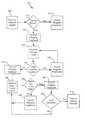
- FIG. 3is a flow diagram of a process for generating and executing a job in accordance with the present invention.
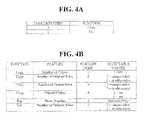
- FIG. 4Ais a table of exemplary function codes.
- FIG. 4Bis a table of exemplary key-value pairs.
- embodiments of the present inventionmay include both hardware and electronic components or modules that, for purposes of discussion, may be illustrated and described as if the majority of the components were implemented solely in hardware.
- the electronic based aspects of the present inventionmay be implemented in software.
- a plurality of hardware and software-based devices, as well as a plurality of different structural componentsmay be utilized to implement the present invention.
- the specific mechanical configurations illustrated in the drawingsare intended to exemplify embodiments of the present invention, and other alternative mechanical configurations are possible.
- an exemplary multi-function peripheral (MFP) device 100includes a scanner, scanning unit or scanning system 105 and an image signal processor 110 .
- the MFP device 100includes a printer or printing unit 115 including a printing processor 120 , an optical system 125 , and an image forming system 130 .
- MFP device 100also includes a memory 135 , a document transporting unit 140 , a duplex unit 145 and an exemplary operation (e.g., input/output) panel 150 .
- the operation panel 150is attached, for example, on top of MFP device 100 for executing operations or functions, such as copying, faxing, scanning, or e-mailing and for displaying device options or conditions, such as duplex copying or stapling.
- operation panel 150may be integrated or housed within MFP device 100 .
- Scanning system 105reads a document and converts the obtained data into an image data.
- Memory unit 135transmits image data and color data, if applicable, to the printing unit 115 either directly, or through a memory installed therein.
- the image data and color datamay also be transmitted to a user's workstation or computer for further processing or storage.
- the image data and color datamay also be transmitted to a desired destination by facsimile or electronic mail.
- operation panel 150can include, for example, a signaling device 200 , such as a sound generating or audio signaling device (e.g., beeper, tone generator, audio speaker, and so forth) and a display screen or touch panel 205 for indicating a warning, such as jamming, a service man call, and paper empty, or other information, attributes or conditions such as a threshold level, magnification ratio, and copy sheet size.
- a signaling device 200such as a sound generating or audio signaling device (e.g., beeper, tone generator, audio speaker, and so forth) and a display screen or touch panel 205 for indicating a warning, such as jamming, a service man call, and paper empty, or other information, attributes or conditions such as a threshold level, magnification ratio, and copy sheet size.
- the MFP devicemay include a data communication device, such as a Bluetooth or Wireless USB transceiver, instead of or in addition to the sound generating or audio signaling device, for communicating with a user's digital receiver, such as may be contained in a Bluetooth-enabled cell phone, over a short-range data communication network, such as a Bluetooth or USB network.
- the MFP devicemay be able to transmit feedback to the user in the form of tones or voice messages over the communication network via equipment already used by the user for other purposes, such as a Bluetooth-enabled cell phone.
- Operation panel 150may also include a keypad or key group 210 for entering input such as the desired number of copies and magnification ratio; a “Clear” key 215 for clearing the input entered at keypad 210 ; a panel “Reset” key 220 for clearing all of the set conditions; a “Stop” key 225 for stopping or halting operation of MFP device 100 ; a “Ready” key 230 for starting or commencing the current or desired operation; a “Copy” key 235 for setting a desired copying mode (e.g., one of single-single side, double-single side, single-double side, double-double side modes, and so forth); and a “Sort” key 240 for setting an electronic sorting mode.
- the functions associated with the keyscan also be communicated through display 205 .
- process 300allows a user to key in functions and associated attributes, instructions and features using keys located on MFP device 100 , without the use of special technology for impaired users, such as an interactive voice response (IVR) system, large viewing screen, screen radar, touch screen or voice recognition system.
- IVRinteractive voice response
- Process 300treats received input as function codes or key-value pairs, associating the received feature and value input with feature, attribute, parameter or instructions associated with the desired function to execute.
- the function codes or key-value pairsare preset or predetermined by the manufacturer.
- the function codes or key-value pairsmay also be set by a system administrator or other person authorized to set up MFP device 100 . For example, as shown in table FIG. 4A , if MFP device 100 is a combined photocopy/facsimile machine, a function code of “1” may represent the “copy” function, and a function code of “2” may represent the “fax” function.
- a copy function feature code of “1”may represent the feature of how many copies to make; a copy function feature code of “2” may represent the number of original sides of the document to be copied; a copy function feature code of “3” may represent the number of output sides of the document to be copied; a copy function feature code of “4” may represent whether the output copies are to be stapled; a fax function feature code of “1” may represent the phone number to which the document is to be faxed; and a fax function feature code of “2” may represent the number of original sides of the document to be faxed.
- the value entered after the function feature codemay represent the actual value associated with the desired feature, attribute or instruction, and acceptable values for such desired feature, attribution or instruction may be preset or predetermined.
- acceptable values for the number of copies featuremay be 1 through 999
- acceptable values for the number of original sides for the document to be copiedmay be “1” or “2,” where “1” equals a single-sided document and “2” equals a double-sided document.
- acceptable values for the number of output sidesmay be “1” or “2,” where “1” equals a single-sided copy and “2” equals a double-sided copy.
- Acceptable values for stapled output copies featuremay be “0” or “1”, where “0” equals no stapled output and “1” equals stapled output.
- Acceptable values for the fax phone number featuremay be numbers only, and acceptable values for the number of original sides of the document to be faxed may be “1” or “2,” where “1” equals a single-sided document and “2” equals a double-sided document.
- FIGS. 4A and 4Bare exemplary, and there may be may other functions and associated features, attributes or instructions that may be preset or predetermined. Additionally, the function code, feature code, and acceptable feature values may vary and be represented in other manners.
- an initiation input signalis received from a user (block 305 ) to return MFP device 100 to a pre-defined home state ready for input.
- the usercan generate such signal by locating and activating or pressing any key or on the operation panel 150 of MFP device 100 or a preset or predetermined button or key, such as an idle or “Ready” key 230 , to begin the job setup and execution process.
- the initiation input signalmay also be numeric input entered at operation panel 150 using keypad 210 or a touchscreen display.
- the initiation input signalmay be the picking up (i.e., off-hook signal) of a telephone headset connected to the operation panel 150 .
- the activation signalmay be a signal generated from a portable auxiliary device being connected to MFP device 150 , such as a flash memory device.
- MFP device 100may verify whether MFP device 100 is ready to receive and perform requested functions. MFP device 100 may also provide the appropriate ready state feedback (blocks 315 , 320 ) to the user, such as through an audio signal or visual display on operation panel 290 . For example, if MFP device 100 is not in a ready state, it may provide negative feedback, such as a “razz” sound, to indicate that a job request cannot be honored, possibly due to, for example, MFP device 100 being in an intervention required state (e.g., out of paper or network down) and that further input is futile.
- MFP device 100may verify whether MFP device 100 is ready to receive and perform requested functions. MFP device 100 may also provide the appropriate ready state feedback (blocks 315 , 320 ) to the user, such as through an audio signal or visual display on operation panel 290 . For example, if MFP device 100 is not in a ready state, it may provide negative feedback, such as a “razz” sound, to indicate that a job request cannot be honored,
- MFP device 100may provide positive feedback, such as a “ding” sound, to indicate that requests can be honored and that MFP device 100 is ready to solicit user selections or input and perform desired functions.
- the display screen 205may flash a certain color, such as red, indicating negative feedback and another color, such as green, indicating positive feedback.
- feedbackmay be provided through a tone or voice message through a user's digital receiver.
- MFP device 100receives a function code, and possibly a delimiter to indicate that the entry of the desired function code is complete, from a user. For example, if a user wishes to perform a copy function, MFP device 100 may receive a “1” and a delimiter, such as an asterisk or pound symbol.
- MFP device 100determines whether the function code received is valid. Validation includes verifying that the function requested will be recognized by MFP device 100 .
- feedbackmay be provided to the user (blocks 335 , 340 ).
- Positive feedbacksuch as sounding a “ding” or voicing a success, indicates that a valid function has been selected (block 335 ), and negative feedback, such as sounding a “razz” or voicing an error, may be signaled an invalid function call (block 340 ). If the function code is invalid, MFP device 100 does not generate a job request.
- MFP device 100may receive key-value pairs representing features, attributes, instructions or parameters associated with the valid function code (block 350 ). Continuing with the copy function example, if a user wishes to make multiple copies, such as 23, MFP device 100 may receive a “1” and first delimiter, such as an asterisk, which indicates that the entry of the desired feature code is complete, and a “23”, and a second delimiter, which indicates that the entry of the value associated with the desired feature code is complete.
- first delimitersuch as an asterisk
- MFP device 100determines whether the key-value pair or feature code and associated feature value received are valid. For example, validation may help ensure that the feature code can be associated with the desired function and recognized by MFP device 100 and that the feature value inputted is valid for the desired feature, attribute, parameter or instruction. Validation may further include checking to make sure that required parameters have been set.
- feedbackmay be provided to the user (blocks 360 , 365 ).
- Positive feedbacksuch as sounding a “ding”, voicing a success or flashing a certain color on display screen 205 , indicates that a valid feature has been selected (block 360 )
- negative feedbacksuch as sounding a “razz”, voicing an error or flashing a different color on display screen 205 , may be signaled for an invalid feature call or if an invalid value is associated with the feature call (block 365 ). If the feature key-value pair is invalid, MFP device 100 ignores the key-value pair.
- the input, validation and feedback processesmay be repeated until all required and desired features, attributes, instructions or parameters have been defined or an indication that the job creation or setup operation is complete, such as an end of input indicator or job creation indicator, a perform function signal, or a job submission indicator, is received (block 370 ).
- an indication that the job creation or setup operation is completesuch as an end of input indicator or job creation indicator, a perform function signal, or a job submission indicator, is received (block 370 ).
- the jobmay also be known as a job program or job ticket. It will be appreciated by one of ordinary skill in the art that validation of the job may also occur after a predetermined number of key-value pair inputs or after an end of input indication is received rather than after each individual key-value pair input.
- the jobis executed using valid received key-value pair inputs.
- a request for a copymay occur as follows.
- the userpresses “Ready” key 230 on operation panel 150 .
- MFP device 100verifies that MFP device is in a ready state, it may provide positive feedback.
- the userthen inputs the desired function code, such a “1” to indicate the copy function, and a delimiter, such as an asterisk or pound symbol, to indicate the function code input is complete.
- MFP device 100verifies that a valid function has been selected, it may provide positive feedback.
- the usermay then enter feature key-value pairs in any format acceptable to MFP device 100 , such as in the format of a feature code, a first delimiter, a feature value and a second delimiter.
- a first delimitersuch as an asterisk
- a second delimitersuch as a pound symbol
- the delimitersmay be any symbol or sequence of symbols recognized by the MFP as an end of input indicator.
- key-value pairsmay be inputted in any order or sequence and that all of the feature key-value pairs associated with a particular function may not be used for in every job request (i.e., only the desired features associated with the desired function need to be inputted).
- MFP device 100After MFP device 100 verifies whether a valid feature key-value pair has been entered, it may provide positive or negative feedback, as appropriate. The user may then attempt to input another key-value pair. Once input a job submission indicator is received, MFP device 100 executes the job request, which is formed from valid key-value pairs received.
- MFP device 100verifies job request upon the receipt of a job submission indicator and executes the job request using only the valid key-value pairs inputted. For example, input by the user of 1*1*23#2*2#4*1## after pressing “Ready” Key 230 would generate a job request for 23 copies of a stapled double-sided document.
- method 300is device 100 .
- method 300is resident in memory of a portable device, such as a flash memory device that can be connected to the MFP device 100 , such as through a Universal Serial Bus (USB).
- a portable devicesuch as a flash memory device that can be connected to the MFP device 100 , such as through a Universal Serial Bus (USB).
- USBUniversal Serial Bus
- plugging the portable device into the MFP device 100initiates process 100 residing in the portable device.
- Embodiments of the present inventioncan be implemented in digital electronic circuitry, or in computer hardware, firmware, software, or in combinations of thereof.
- Embodiments of the present inventioncan be implemented as a computer program product, i.e., a computer program tangibly embodied in an information carrier, e.g., in a machine readable storage device or in a propagated signal, for execution by, or to control the operation of, data processing apparatus, e.g., a programmable processor, a computer, or multiple computers.
- a computer programcan be written in any form of programming language, including compiled or interpreted languages, and it can be deployed in any form, including as a stand alone program or as a module, component, subroutine, or other unit suitable for use in a computing environment.
- a computer programcan be deployed to be executed on one computer or on multiple computers at one site or distributed across multiple sites and interconnected by a communication network.
- the exemplary embodiments of the present inventioncan be performed by one or more programmable processors executing a computer program to perform functions of the present invention by operating on input data and generating output.
- the exemplary embodimentscan also be performed by, and apparatus of the present invention can be implemented as, special purpose logic circuitry, e.g., an FPGA (field programmable gate array) or an ASIC (application specific integrated circuit).
- processors suitable for the execution of a computer programinclude, by way of example, both general and special purpose microprocessors, and any one or more processors of any kind of digital computer.
- a processorwill receive instructions and data from a read only memory or a random access memory or both.
- the essential elements of a computerare a processor for executing instructions and one or more memory devices for storing instructions and data.
- a computerwill also include, or be operatively coupled to receive data from or transfer data to, or both, one or more mass storage devices for storing data, e.g., magnetic, magneto optical disks, or optical disks.
- Information carriers suitable for embodying computer program instructions and datainclude all forms of non volatile memory, including by way of example semiconductor memory devices, e.g., EPROM, EEPROM, and flash memory devices; magnetic disks, e.g., internal hard disks or removable disks; magneto optical disks; and CD ROM and DVD-ROM disks.
- semiconductor memory devicese.g., EPROM, EEPROM, and flash memory devices
- magnetic diskse.g., internal hard disks or removable disks
- magneto optical diskse.g., CD ROM and DVD-ROM disks.
- the processor and the memorycan be supplemented by, or incorporated in special purpose logic circuitry.
Landscapes
- Engineering & Computer Science (AREA)
- Theoretical Computer Science (AREA)
- Physics & Mathematics (AREA)
- General Physics & Mathematics (AREA)
- General Engineering & Computer Science (AREA)
- General Health & Medical Sciences (AREA)
- Health & Medical Sciences (AREA)
- Computer Hardware Design (AREA)
- Bioethics (AREA)
- Computer Security & Cryptography (AREA)
- Software Systems (AREA)
- Audiology, Speech & Language Pathology (AREA)
- Business, Economics & Management (AREA)
- Educational Administration (AREA)
- Educational Technology (AREA)
- Facsimiles In General (AREA)
Abstract
Description
Claims (19)
Priority Applications (1)
| Application Number | Priority Date | Filing Date | Title |
|---|---|---|---|
| US11/554,313US8185957B2 (en) | 2006-10-30 | 2006-10-30 | Peripheral device |
Applications Claiming Priority (1)
| Application Number | Priority Date | Filing Date | Title |
|---|---|---|---|
| US11/554,313US8185957B2 (en) | 2006-10-30 | 2006-10-30 | Peripheral device |
Publications (2)
| Publication Number | Publication Date |
|---|---|
| US20080115222A1 US20080115222A1 (en) | 2008-05-15 |
| US8185957B2true US8185957B2 (en) | 2012-05-22 |
Family
ID=39370745
Family Applications (1)
| Application Number | Title | Priority Date | Filing Date |
|---|---|---|---|
| US11/554,313Active2030-03-29US8185957B2 (en) | 2006-10-30 | 2006-10-30 | Peripheral device |
Country Status (1)
| Country | Link |
|---|---|
| US (1) | US8185957B2 (en) |
Cited By (1)
| Publication number | Priority date | Publication date | Assignee | Title |
|---|---|---|---|---|
| US20080144077A1 (en)* | 2006-10-31 | 2008-06-19 | Mohamed Nooman Ahmed | Access to networked peripheral device for impaired users |
Families Citing this family (3)
| Publication number | Priority date | Publication date | Assignee | Title |
|---|---|---|---|---|
| US20080144134A1 (en)* | 2006-10-31 | 2008-06-19 | Mohamed Nooman Ahmed | Supplemental sensory input/output for accessibility |
| JP2016035514A (en)* | 2014-08-04 | 2016-03-17 | キヤノン株式会社 | Printer, control method of printer, and program |
| CN114398033B (en)* | 2021-12-22 | 2024-05-14 | 陕西法士特齿轮有限责任公司 | Interface and data stripping design method |
Citations (26)
| Publication number | Priority date | Publication date | Assignee | Title |
|---|---|---|---|---|
| US4414537A (en) | 1981-09-15 | 1983-11-08 | Bell Telephone Laboratories, Incorporated | Digital data entry glove interface device |
| US4937762A (en)* | 1987-03-19 | 1990-06-26 | Kabushiki Kaisha Toshiba | Method and apparatus for combination information display and input operations |
| US5589855A (en)* | 1992-08-14 | 1996-12-31 | Transaction Technology, Inc. | Visually impaired customer activated terminal method and system |
| US5642131A (en) | 1992-05-07 | 1997-06-24 | Kensington Microware Limited | Method and apparatus for cursor positioning |
| US5734923A (en) | 1993-09-22 | 1998-03-31 | Hitachi, Ltd. | Apparatus for interactively editing and outputting sign language information using graphical user interface |
| US5736978A (en) | 1995-05-26 | 1998-04-07 | The United States Of America As Represented By The Secretary Of The Air Force | Tactile graphics display |
| US5896129A (en) | 1996-09-13 | 1999-04-20 | Sony Corporation | User friendly passenger interface including audio menuing for the visually impaired and closed captioning for the hearing impaired for an interactive flight entertainment system |
| US6061666A (en) | 1996-12-17 | 2000-05-09 | Citicorp Development Center | Automatic bank teller machine for the blind and visually impaired |
| US6267598B1 (en) | 1996-06-21 | 2001-07-31 | Robert H. Allen, Jr. | Touch activated audio module and sign |
| US6278441B1 (en) | 1997-01-09 | 2001-08-21 | Virtouch, Ltd. | Tactile interface system for electronic data display system |
| US6464135B1 (en) | 1999-06-30 | 2002-10-15 | Citicorp Development Center, Inc. | Method and system for assisting the visually impaired in performing financial transactions |
| US6496182B1 (en) | 1995-06-07 | 2002-12-17 | Microsoft Corporation | Method and system for providing touch-sensitive screens for the visually impaired |
| US20030036909A1 (en)* | 2001-08-17 | 2003-02-20 | Yoshinaga Kato | Methods and devices for operating the multi-function peripherals |
| US6549789B1 (en) | 2000-04-28 | 2003-04-15 | Motorola Inc. | Portable electronic device with an adaptable user interface |
| US6636202B2 (en) | 2001-04-27 | 2003-10-21 | International Business Machines Corporation | Interactive tactile display for computer screen |
| US6760408B2 (en) | 2002-10-03 | 2004-07-06 | Cingular Wireless, Llc | Systems and methods for providing a user-friendly computing environment for the hearing impaired |
| US6856333B2 (en) | 2001-04-30 | 2005-02-15 | International Business Machines Corporation | Providing a user interactive interface for physically impaired users dynamically modifiable responsive to preliminary user capability testing |
| US6883981B2 (en) | 2002-12-05 | 2005-04-26 | Canon Kabushiki Kaisha | Printing control method and apparatus |
| US6917437B1 (en) | 1999-06-29 | 2005-07-12 | Xerox Corporation | Resource management for a printing system via job ticket |
| US6918091B2 (en) | 2000-11-09 | 2005-07-12 | Change Tools, Inc. | User definable interface system, method and computer program product |
| US6950205B2 (en) | 2002-04-19 | 2005-09-27 | Canon Kabushiki Kaisha | Peripheral device managing system, job sending method and storing medium |
| US6952577B2 (en) | 2002-04-16 | 2005-10-04 | Avaya Technology Corp. | Auditory methods for providing information about a telecommunication system's settings and status |
| US7162685B2 (en)* | 2000-07-24 | 2007-01-09 | Fujitsu Limited | Key-input correcting device |
| US20070076241A1 (en)* | 2005-09-30 | 2007-04-05 | Brother Kogyo Kabushiki Kaisha | Multi function peripheral |
| US7440709B2 (en)* | 2005-01-14 | 2008-10-21 | Canon Kabushiki Kaisha | Printing system, job processing method, and storage medium |
| US7494050B1 (en)* | 2004-06-29 | 2009-02-24 | Diebold Self-Service Systems Division Of Diebold, Incorporated | Automated banking machine audible user interface method |
- 2006
- 2006-10-30USUS11/554,313patent/US8185957B2/enactiveActive
Patent Citations (26)
| Publication number | Priority date | Publication date | Assignee | Title |
|---|---|---|---|---|
| US4414537A (en) | 1981-09-15 | 1983-11-08 | Bell Telephone Laboratories, Incorporated | Digital data entry glove interface device |
| US4937762A (en)* | 1987-03-19 | 1990-06-26 | Kabushiki Kaisha Toshiba | Method and apparatus for combination information display and input operations |
| US5642131A (en) | 1992-05-07 | 1997-06-24 | Kensington Microware Limited | Method and apparatus for cursor positioning |
| US5589855A (en)* | 1992-08-14 | 1996-12-31 | Transaction Technology, Inc. | Visually impaired customer activated terminal method and system |
| US5734923A (en) | 1993-09-22 | 1998-03-31 | Hitachi, Ltd. | Apparatus for interactively editing and outputting sign language information using graphical user interface |
| US5736978A (en) | 1995-05-26 | 1998-04-07 | The United States Of America As Represented By The Secretary Of The Air Force | Tactile graphics display |
| US6496182B1 (en) | 1995-06-07 | 2002-12-17 | Microsoft Corporation | Method and system for providing touch-sensitive screens for the visually impaired |
| US6267598B1 (en) | 1996-06-21 | 2001-07-31 | Robert H. Allen, Jr. | Touch activated audio module and sign |
| US5896129A (en) | 1996-09-13 | 1999-04-20 | Sony Corporation | User friendly passenger interface including audio menuing for the visually impaired and closed captioning for the hearing impaired for an interactive flight entertainment system |
| US6061666A (en) | 1996-12-17 | 2000-05-09 | Citicorp Development Center | Automatic bank teller machine for the blind and visually impaired |
| US6278441B1 (en) | 1997-01-09 | 2001-08-21 | Virtouch, Ltd. | Tactile interface system for electronic data display system |
| US6917437B1 (en) | 1999-06-29 | 2005-07-12 | Xerox Corporation | Resource management for a printing system via job ticket |
| US6464135B1 (en) | 1999-06-30 | 2002-10-15 | Citicorp Development Center, Inc. | Method and system for assisting the visually impaired in performing financial transactions |
| US6549789B1 (en) | 2000-04-28 | 2003-04-15 | Motorola Inc. | Portable electronic device with an adaptable user interface |
| US7162685B2 (en)* | 2000-07-24 | 2007-01-09 | Fujitsu Limited | Key-input correcting device |
| US6918091B2 (en) | 2000-11-09 | 2005-07-12 | Change Tools, Inc. | User definable interface system, method and computer program product |
| US6636202B2 (en) | 2001-04-27 | 2003-10-21 | International Business Machines Corporation | Interactive tactile display for computer screen |
| US6856333B2 (en) | 2001-04-30 | 2005-02-15 | International Business Machines Corporation | Providing a user interactive interface for physically impaired users dynamically modifiable responsive to preliminary user capability testing |
| US20030036909A1 (en)* | 2001-08-17 | 2003-02-20 | Yoshinaga Kato | Methods and devices for operating the multi-function peripherals |
| US6952577B2 (en) | 2002-04-16 | 2005-10-04 | Avaya Technology Corp. | Auditory methods for providing information about a telecommunication system's settings and status |
| US6950205B2 (en) | 2002-04-19 | 2005-09-27 | Canon Kabushiki Kaisha | Peripheral device managing system, job sending method and storing medium |
| US6760408B2 (en) | 2002-10-03 | 2004-07-06 | Cingular Wireless, Llc | Systems and methods for providing a user-friendly computing environment for the hearing impaired |
| US6883981B2 (en) | 2002-12-05 | 2005-04-26 | Canon Kabushiki Kaisha | Printing control method and apparatus |
| US7494050B1 (en)* | 2004-06-29 | 2009-02-24 | Diebold Self-Service Systems Division Of Diebold, Incorporated | Automated banking machine audible user interface method |
| US7440709B2 (en)* | 2005-01-14 | 2008-10-21 | Canon Kabushiki Kaisha | Printing system, job processing method, and storage medium |
| US20070076241A1 (en)* | 2005-09-30 | 2007-04-05 | Brother Kogyo Kabushiki Kaisha | Multi function peripheral |
Cited By (2)
| Publication number | Priority date | Publication date | Assignee | Title |
|---|---|---|---|---|
| US20080144077A1 (en)* | 2006-10-31 | 2008-06-19 | Mohamed Nooman Ahmed | Access to networked peripheral device for impaired users |
| US8743388B2 (en)* | 2006-10-31 | 2014-06-03 | Lexmark International, Inc. | Access to networked peripheral device for impaired users |
Also Published As
| Publication number | Publication date |
|---|---|
| US20080115222A1 (en) | 2008-05-15 |
Similar Documents
| Publication | Publication Date | Title |
|---|---|---|
| EP2182714B1 (en) | Image processing apparatus and image processing apparatus control method | |
| US20120075658A1 (en) | Image forming apparatus, image forming system, and image forming method that cause a job execution screen to be displayed on a display of a terminal apparatus | |
| JP4321604B2 (en) | MFP, password setting system and password setting program | |
| JP4009568B2 (en) | Device management system and device management method | |
| US20110051179A1 (en) | Facsimile device, image forming device, communication system, communication method and program storage medium | |
| US8743388B2 (en) | Access to networked peripheral device for impaired users | |
| US8185957B2 (en) | Peripheral device | |
| JP2019201282A (en) | Image processing apparatus and control program therefor | |
| US20160182761A1 (en) | Image forming apparatus | |
| US10791230B2 (en) | Image forming apparatus, instruction acceptance method, and computer readable program | |
| JP6045533B2 (en) | Document management apparatus and document management program | |
| JP2010176701A (en) | Authentication agent, device customizing system, and program | |
| US20080144134A1 (en) | Supplemental sensory input/output for accessibility | |
| US10956094B2 (en) | Systems and methods for providing assistance through one or more voice-based instructions via multi-function device | |
| CN103095950A (en) | Operation Device, Operation Method And Image Formation Device | |
| US9699333B2 (en) | Image forming system including a portable terminal device | |
| JP5358490B2 (en) | Image forming system and user manager server device | |
| JP6558342B2 (en) | Image forming system, communication terminal apparatus, image forming apparatus, and server | |
| JP2009284194A (en) | Information processor and information processing program | |
| JP2007316739A (en) | Document management device | |
| JP6711190B2 (en) | Information processing device, information processing system, and information processing program | |
| JP2013012042A (en) | Image processing device, image processing system, and authentication device | |
| JP2019185606A (en) | Job information display system, job information display device, job information display method, and computer program | |
| JP4420129B2 (en) | Password setting system and password setting program | |
| US20200036851A1 (en) | Image Forming Apparatus, Medium Storing Program for Controlling Image Forming Apparatus, and Method of Controlling Image Forming Apparatus |
Legal Events
| Date | Code | Title | Description |
|---|---|---|---|
| AS | Assignment | Owner name:LEXMARK INTERNATIONAL, INC., KENTUCKY Free format text:ASSIGNMENT OF ASSIGNORS INTEREST;ASSIGNORS:AHMED, MOHAMED N.;BRIDGES, AMANDA KAY;DANIEL, STUART WILLARD;AND OTHERS;REEL/FRAME:018464/0332 Effective date:20061004 | |
| STCF | Information on status: patent grant | Free format text:PATENTED CASE | |
| FPAY | Fee payment | Year of fee payment:4 | |
| AS | Assignment | Owner name:CHINA CITIC BANK CORPORATION LIMITED, GUANGZHOU BR Free format text:PATENT SECURITY AGREEMENT;ASSIGNOR:LEXMARK INTERNATIONAL, INC.;REEL/FRAME:046989/0396 Effective date:20180402 | |
| AS | Assignment | Owner name:CHINA CITIC BANK CORPORATION LIMITED, GUANGZHOU BR Free format text:CORRECTIVE ASSIGNMENT TO CORRECT THE INCORRECT U.S. PATENT NUMBER PREVIOUSLY RECORDED AT REEL: 046989 FRAME: 0396. ASSIGNOR(S) HEREBY CONFIRMS THE PATENT SECURITY AGREEMENT;ASSIGNOR:LEXMARK INTERNATIONAL, INC.;REEL/FRAME:047760/0795 Effective date:20180402 | |
| MAFP | Maintenance fee payment | Free format text:PAYMENT OF MAINTENANCE FEE, 8TH YEAR, LARGE ENTITY (ORIGINAL EVENT CODE: M1552); ENTITY STATUS OF PATENT OWNER: LARGE ENTITY Year of fee payment:8 | |
| FEPP | Fee payment procedure | Free format text:MAINTENANCE FEE REMINDER MAILED (ORIGINAL EVENT CODE: REM.); ENTITY STATUS OF PATENT OWNER: LARGE ENTITY | |
| AS | Assignment | Owner name:LEXMARK INTERNATIONAL, INC., KENTUCKY Free format text:RELEASE BY SECURED PARTY;ASSIGNOR:CHINA CITIC BANK CORPORATION LIMITED, GUANGZHOU BRANCH, AS COLLATERAL AGENT;REEL/FRAME:066345/0026 Effective date:20220713 | |
| FEPP | Fee payment procedure | Free format text:11.5 YR SURCHARGE- LATE PMT W/IN 6 MO, LARGE ENTITY (ORIGINAL EVENT CODE: M1556); ENTITY STATUS OF PATENT OWNER: LARGE ENTITY | |
| MAFP | Maintenance fee payment | Free format text:PAYMENT OF MAINTENANCE FEE, 12TH YEAR, LARGE ENTITY (ORIGINAL EVENT CODE: M1553); ENTITY STATUS OF PATENT OWNER: LARGE ENTITY Year of fee payment:12 |