US8184938B2 - Rear-installable fiber optic modules and equipment - Google Patents
Rear-installable fiber optic modules and equipmentDownload PDFInfo
- Publication number
- US8184938B2 US8184938B2US12/323,423US32342308AUS8184938B2US 8184938 B2US8184938 B2US 8184938B2US 32342308 AUS32342308 AUS 32342308AUS 8184938 B2US8184938 B2US 8184938B2
- Authority
- US
- United States
- Prior art keywords
- fiber optic
- module
- chassis
- tray
- disposed
- Prior art date
- Legal status (The legal status is an assumption and is not a legal conclusion. Google has not performed a legal analysis and makes no representation as to the accuracy of the status listed.)
- Active, expires
Links
Images


Classifications
- G—PHYSICS
- G02—OPTICS
- G02B—OPTICAL ELEMENTS, SYSTEMS OR APPARATUS
- G02B6/00—Light guides; Structural details of arrangements comprising light guides and other optical elements, e.g. couplings
- G02B6/44—Mechanical structures for providing tensile strength and external protection for fibres, e.g. optical transmission cables
- G02B6/4439—Auxiliary devices
- G02B6/444—Systems or boxes with surplus lengths
- G02B6/4452—Distribution frames
- G02B6/44526—Panels or rackmounts covering a whole width of the frame or rack
- G—PHYSICS
- G02—OPTICS
- G02B—OPTICAL ELEMENTS, SYSTEMS OR APPARATUS
- G02B6/00—Light guides; Structural details of arrangements comprising light guides and other optical elements, e.g. couplings
- G02B6/44—Mechanical structures for providing tensile strength and external protection for fibres, e.g. optical transmission cables
- G02B6/4439—Auxiliary devices
- G02B6/4471—Terminating devices ; Cable clamps
- G—PHYSICS
- G02—OPTICS
- G02B—OPTICAL ELEMENTS, SYSTEMS OR APPARATUS
- G02B6/00—Light guides; Structural details of arrangements comprising light guides and other optical elements, e.g. couplings
- G02B6/44—Mechanical structures for providing tensile strength and external protection for fibres, e.g. optical transmission cables
- G02B6/4439—Auxiliary devices
- G02B6/444—Systems or boxes with surplus lengths
- G02B6/4453—Cassettes
- G02B6/4455—Cassettes characterised by the way of extraction or insertion of the cassette in the distribution frame, e.g. pivoting, sliding, rotating or gliding
- G—PHYSICS
- G02—OPTICS
- G02B—OPTICAL ELEMENTS, SYSTEMS OR APPARATUS
- G02B6/00—Light guides; Structural details of arrangements comprising light guides and other optical elements, e.g. couplings
- G02B6/24—Coupling light guides
- G02B6/36—Mechanical coupling means
- G02B6/38—Mechanical coupling means having fibre to fibre mating means
- G02B6/3807—Dismountable connectors, i.e. comprising plugs
- G02B6/3897—Connectors fixed to housings, casing, frames or circuit boards
- G—PHYSICS
- G02—OPTICS
- G02B—OPTICAL ELEMENTS, SYSTEMS OR APPARATUS
- G02B6/00—Light guides; Structural details of arrangements comprising light guides and other optical elements, e.g. couplings
- G02B6/44—Mechanical structures for providing tensile strength and external protection for fibres, e.g. optical transmission cables
- G02B6/4439—Auxiliary devices
- G02B6/444—Systems or boxes with surplus lengths
- G02B6/4452—Distribution frames
- G—PHYSICS
- G02—OPTICS
- G02B—OPTICAL ELEMENTS, SYSTEMS OR APPARATUS
- G02B6/00—Light guides; Structural details of arrangements comprising light guides and other optical elements, e.g. couplings
- G02B6/44—Mechanical structures for providing tensile strength and external protection for fibres, e.g. optical transmission cables
- G02B6/4439—Auxiliary devices
- G02B6/444—Systems or boxes with surplus lengths
- G02B6/4453—Cassettes
Definitions
- the technology of the disclosurerelates to fiber optic modules provided in fiber optic equipment to support fiber optic connections.
- optical fiber useincludes extremely wide bandwidth and low noise operation. Because of these advantages, optical fiber is increasingly being used for a variety of applications, including but not limited to broadband voice, video, and data transmission. Fiber optic networks employing optical fiber are being developed and used to deliver voice, video, and data transmissions to subscribers over both private and public networks. These fiber optic networks often include separated connection points at which it is necessary to link optical fibers in order to provide “live fiber” from one connection point to another connection point. In this regard, fiber optic equipment is located in data distribution centers or central offices to support interconnections.
- the fiber optic equipmentis customized based on the application need.
- the fiber optic equipmentis typically included in housings that are mounted in equipment racks to maximize space.
- One example of such fiber optic equipmentis a fiber optic module.
- a fiber optic moduleis designed to provide cable-to-cable fiber optic connections and manage the polarity of fiber optic cable connections.
- the fiber optic moduleis typically mounted to a chassis which is then mounted inside an equipment rack or housing.
- the chassismay be provided in the form of a tray that is extendable from the equipment rack like a drawer. This allows a technician access to fiber optic adapters disposed in the fiber optic module and any fiber optic cables connected to the fiber optic adapters without removing the fiber optic module from the equipment rack.
- the field techniciantypically loads trunk cables in the rear section of a fiber optic equipment rack.
- the field technicianthen feeds the connectorized fanout legs from the trunk cable to the front of the equipment rack.
- the field technicianthen walks around to the front of the equipment rack to connect the fanout legs to a fiber optic module.
- data distribution centersare typically large facilities with significant numbers of equipment racks, walking back and forth from the rear section to the front section of the equipment rack during an installation can take significant time.
- a second technicianmay work in tandem with the first technician, where the first technician manages loading of fiber optic cables in the rear section of the equipment rack.
- the second technicianremains in the front of the rack to install the fiber optic modules and establish optical connections between the fiber optic cables and the fiber optic modules.
- fiber optic cablesare installed in the rear section of the equipment rack and the fiber optic modules and connections are installed from the front of the equipment rack thereby requiring extensive labor.
- Embodiments disclosed in the detailed descriptioninclude fiber optic equipment that supports one or more rear-installable fiber optic modules.
- the fiber optic modulesare configured to support fiber optic connections.
- the fiber optic equipmentis comprised of a chassis defining a front end and a rear section.
- At least one guide systemis disposed in the chassis and configured to receive at least one fiber optic module.
- the guide systemmay be provided in the form of a rail guide system.
- the guide systemreceives a fiber optic module from the rear section of the chassis and is configured to guide the fiber optic module toward the front end of the chassis. In this manner, a technician can make fiber optic connections to fiber optic modules and also install the fiber optic modules into the fiber optic equipment from the rear section of the chassis to reduce time and/or labor in making fiber optic connections.
- the guide systemis comprised of at least one tray guide that receives at least one fiber optic equipment tray.
- the tray guidesare disposed in the chassis of the fiber optic equipment.
- the tray guidessupport fiber optic equipment trays within the fiber optic equipment.
- At least one module guideis disposed in the fiber optic equipment trays to support one or more fiber optic modules. In this manner, the fiber optic equipment tray can translate within the chassis to move the fiber optic modules supported by the fiber optic equipment tray about the chassis.
- the module guidesalso allow fiber optic modules to be rear-installable into the fiber optic equipment tray to be rear-installable in the fiber optic equipment.
- the tray guides disposed in the fiber optic equipment trayalso allow the fiber optic modules disposed therein to be independently translated within the fiber optic equipment tray.
- the guide systemis comprised of at least one module guide that receives at least one fiber optic module.
- the module guidesare disposed in the chassis without intermediate fiber optic equipment trays.
- the module guidessupport one or more fiber optic modules. In this manner, the fiber optic modules translate within the chassis to move the fiber optic modules about the chassis.
- the module rail guidesalso allow fiber optic modules to be rear-installable into the chassis to be rear-installable in the fiber optic equipment.
- Module guides disposed in the chassisalso allow the fiber optic modules to be independently translated within the module guides within the chassis.
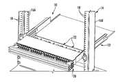
- FIG. 1is a front perspective view of an exemplary fiber optic equipment rack with exemplary fiber optic equipment supporting rear-installable fiber optic modules according to one embodiment
- FIG. 2Ais a rear perspective view of the fiber optic equipment supporting the rear-installable fiber optic modules of FIG. 1 ;
- FIG. 2Bis a perspective view of fiber optic equipment tray guides disposed in the fiber optic equipment of FIG. 1 ;
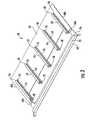
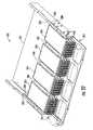
- FIG. 3is a front perspective view of an individual fiber optic equipment tray in the fiber optic equipment of FIG. 1 without rear-installable fiber optic modules installed in module guides disposed in the fiber optic equipment tray;
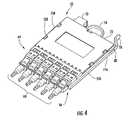
- FIG. 4is a front perspective view of a fiber optic module that is rear-installable in the fiber optic equipment tray of FIG. 3 ;
- FIG. 5is a rear perspective close-up view of the rear-installable fiber optic module of FIG. 4 installed in the fiber optic equipment tray of FIG. 3 ;
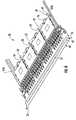
- FIG. 6is a front perspective view of the fiber optic equipment tray of FIG. 3 with rear-installable fiber optic modules installed in the module guides;
- FIG. 7is a front perspective close-up view of the fiber optic equipment tray of FIG. 3 with rear-installable fiber optic modules installed in the module guides;
- FIG. 8is a front perspective view of a fiber optic equipment tray extended from the fiber optic equipment
- FIG. 9is a front perspective view of a fiber routing guide tray of a fiber optic equipment tray lowered to obtain front access to the fiber optic modules supported in the fiber optic equipment tray;
- FIG. 10is a front perspective view of another exemplary fiber optic equipment supporting rear-installable fiber optic modules disposed in module guides;
- FIG. 11is a rear perspective view of the fiber optic equipment supporting the rear-installable fiber optic modules of FIG. 10 ;
- FIG. 12is a front perspective view of an individual fiber optic equipment tray in the fiber optic equipment of FIG. 10 ;
- FIG. 13is a rear perspective view of the rear-installable fiber optic module installed in the module guides disposed in the fiber optic equipment of FIG. 10 ;
- FIG. 14is a rear perspective close-up view of the rear-installable fiber optic module disposed within module guides in the fiber optic equipment of FIG. 10 and locked into the fiber optic equipment tray of FIG. 12 when the fiber optic module is pulled forward;
- FIG. 15is a rear perspective view of the fiber optic module in FIG. 14 ;
- FIG. 16Ais a perspective close-up view of a front locking latch in the fiber optic module of FIG. 15 ;
- FIG. 16Bis a perspective close-up view of a rear lock in the fiber optic module of FIG. 15 ;
- FIG. 17is a rear perspective close-up view of the rear-installable fiber optic modules installed in module guides;
- FIG. 18is a perspective view of the locking features to lock fiber optic modules to fiber optic equipment tray and the fiber optic equipment trays to the chassis of the fiber optic equipment of FIG. 10 ;
- FIG. 19is a front perspective view of the fiber optic equipment of FIG. 10 with rear-installable fiber optic modules disposed in the module guides;
- FIG. 20is a side cross-sectional view of the fiber optic equipment of FIG. 10 with rear-installable fiber optic modules disposed in the module guides and interlocked with the fiber optic equipment trays, with one fiber optic equipment tray extended forward;
- FIG. 21is a front perspective view of the fiber optic equipment of FIG. 20 ;
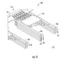
- FIG. 22is a front perspective view of another exemplary fiber optic equipment supporting rear-installable fiber optic modules
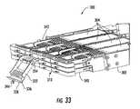
- FIG. 23is a rear perspective view of the fiber optic equipment supporting the rear-installable fiber optic modules of FIG. 22 ;
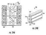
- FIG. 24Ais a front view of a module guide supporting rear-installable fiber optic modules in the fiber optic equipment of FIG. 22 ;
- FIG. 24Bis a perspective view of the module guide illustrated in FIG. 24A ;
- FIG. 25is a front perspective view of the fiber optic modules disposed in the module guides provided in the fiber optic equipment of FIG. 22 ;
- FIGS. 26A and 26Bare a front view of the fiber optic equipment of FIG. 22 with fiber optic modules installed in all module guides and a locking feature to prevent the fiber optic modules from being pulled forward beyond a front end of the fiber optic equipment;
- FIG. 27is a top view of a fiber optic module supported by module guides disposed in the fiber optic equipment of FIG. 22 ;
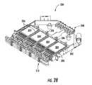
- FIG. 28is a front perspective view of another exemplary fiber optic equipment supporting rear-installable fiber optic modules
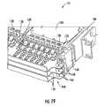
- FIG. 29is a rear perspective view of the fiber optic equipment supporting the rear-installable fiber optic modules of FIG. 28 ;
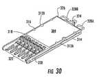
- FIG. 30is a front perspective view of the fiber optic modules provided in the fiber optic equipment of FIG. 22 ;
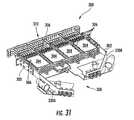
- FIG. 31is another rear perspective view of the fiber optic equipment supporting the rear-installable fiber optic modules of FIG. 28 ;
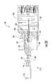
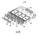
- FIG. 32is another front perspective view of the fiber optic equipment supporting the rear-installable fiber optic modules of FIG. 28 with a fiber routing tray extended and tilted downward to provide access to certain fiber optic modules;
- FIG. 33is another front perspective view of the fiber optic equipment supporting the rear-installable fiber optic modules of FIG. 28 with the fiber routing tray extended and tilted downward;
- FIG. 34is a front perspective view of another exemplary fiber optic equipment supporting rear-installable fiber optic modules.
- FIG. 35is another front perspective view of another exemplary fiber optic equipment supporting rear-installable fiber optic modules.
- Embodiments disclosed in the detailed descriptioninclude fiber optic equipment that supports one or more rear-installable fiber optic modules.
- the fiber optic modulesare configured to support fiber optic connections.
- the fiber optic equipmentis comprised of a chassis defining a front end and a rear section.
- At least one guide systemis disposed in the chassis and configured to receive at least one fiber optic module.
- the guide systemmay be provided in the form of a rail guide system.
- the guide systemreceives a fiber optic module from the rear section of the chassis and is configured to guide the fiber optic module toward the front end of the chassis. In this manner, a technician can make fiber optic connections to fiber optic modules and also install the fiber optic modules into the fiber optic equipment from the rear section of the chassis to reduce time and/or labor in making fiber optic connections.
- the guide systemis comprised of at least one tray guide that receives at least one fiber optic equipment tray.
- the tray guidesare disposed in the chassis of the fiber optic equipment.
- the tray guidessupport fiber optic equipment trays within the fiber optic equipment.
- At least one module guideis disposed in the fiber optic equipment trays to support one or more fiber optic modules. In this manner, the fiber optic equipment tray can translate within the chassis to move the fiber optic modules supported by the fiber optic equipment tray about the chassis.
- the module guidesalso allow fiber optic modules to be rear-installable into the fiber optic equipment tray to be rear-installable in the fiber optic equipment.
- the tray guides disposed in the fiber optic equipment trayalso allow the fiber optic modules disposed therein to be independently translated within the fiber optic equipment tray.
- FIG. 1illustrates an exemplary fiber optic equipment 10 in this regard.
- the exemplary fiber optic equipment 10may be provided at a data distribution center or central office to support cable-to-cable fiber optic connections and to manage a plurality of fiber optic cable connections.
- the fiber optic equipment 10has one or more fiber optic equipment trays that each support one or more rear-installable fiber optic modules.
- the fiber optic modulescan be fiber optic adapter modules or any other type of fiber optic modules or fiber optic apparatuses, including those that support fiber optic connections. Both the fiber optic modules and the fiber optic equipment trays are rear-installable, meaning they can be installed from a rear section of the fiber optic equipment 10 . Further, both the fiber optic equipment trays and the fiber optic modules supported therein are independently translatable about the chassis for installation, access, and/or removal.
- the fiber optic equipment 10includes a fiber optic equipment chassis 12 (“chassis 12 ”).
- the chassis 12is shown as being installed in a fiber optic equipment rack 14 .
- the fiber optic equipment rack 14contains two vertical rails 16 A, 16 B that extend vertically and include a series of apertures 18 for facilitating attachment of the fiber optic equipment 10 inside the fiber optic equipment rack 14 .
- the fiber optic equipment 10is attached and supported by the fiber optic equipment rack 14 in the form of shelves that are stacked on top of each other within the vertical rails 16 A, 16 B. As illustrated, the fiber optic equipment 10 is attached to the vertical rails 16 A, 16 B.
- the fiber optic equipment rack 14may support 1U-sized shelves, with “U” equal a standard 1.75 inches in height.
- the fiber optic equipment 10includes a plurality of extendable fiber optic equipment trays 20 that each carries one or more rear-installable fiber optic modules 22 .
- the fiber optic equipment 10provides a density of 144 fibers, although it is not limited to this density.
- each fiber optic equipment tray 20is independently translatable and accessible to access the fiber optic modules supported therein.
- FIG. 2Aillustrates a rear perspective view of the fiber optic equipment 10 illustrated in FIG. 1 .
- the fiber optic equipment 10is provided in the chassis 12 that defines a front end 24 , a rear section 26 , a first end 28 , and a second end 30 .
- the first end 28 of the chassis 12is disposed on the opposite side of the second end 30 of the chassis 12 .
- a guide system in the form of a rail guide system 32is provided to support the rear-installable fiber optic modules 22 .
- the rail guide system 32comprises two tray rail guides 32 A, 32 B attached to the chassis 12 on the first end 28 and the second end 30 , respectively.
- the tray rail guides 32 A, 32 Bare configured to support one or more fiber optic equipment trays that support the fiber optic modules 22 , which will be illustrated in FIG.
- the tray rail guides 32 A, 32 Ballow each fiber optic equipment tray 20 installed therein to be translated about the chassis 12 .
- the chassis 12supports three (3) fiber optic equipment trays 20 with each one stacked on top of each other.
- a tray cover 34is disposed on top of the top fiber optic equipment tray 20 disposed in the chassis 12 and within the tray rail guides 32 A, 32 B.
- each fiber optic equipment tray 20contains a fiber routing tray 36 attached thereto to support routing of optical fibers connected to the fiber optic modules 22 .
- the fiber routing tray 36can be extended and lowered as desired to obtain access to the fiber optic modules 22 from the front end 24 of the fiber optic equipment 10 .
- FIG. 2Billustrates the tray rail guides 32 A, 32 B in more detail.
- the tray rail guides 32 A, 32 Bform a series of channels 38 A- 38 C, wherein each channel 38 A- 38 C is configured to receive a fiber optic equipment tray 20 .
- the tray rail guides 32 A, 32 Ballow a plurality of fiber optic trays 20 arranged in a column format.
- the tray rail guides 32 A, 32 Bcomprise an end portion 40 by which the channels 38 A- 38 C stop and the fiber optic equipment trays 20 cannot extend beyond. This end portion 40 is disposed in an orientation such that it is adjacent the rear section 26 of the fiber optic equipment 10 .
- the tray rail guides 32 A, 32 Balso contain an entry portion 42 through which the fiber optic equipment trays 20 can be inserted into the channels 38 A- 38 C. Note that the entry portion 42 does not close off the channels 38 A- 38 C such that the fiber optic equipment trays 20 can be extended beyond the entry portion 42 back towards the rear section 26 of the chassis 12 . In this manner, the tray rail guides 32 A, 32 B support rear installation of fiber optic equipment trays 20 into the chassis 12 from the rear section 26 .
- FIG. 3illustrates an individual fiber optic equipment tray 20 not disposed in the chassis 12 or contained within the tray rail guides 32 A, 32 B for further discussion and illustration.
- the fiber optic equipment tray 20contains a main tray portion 44 and the fiber routing tray 36 attached thereto.
- the fiber routing tray 36is attached to the main tray portion 44 via hinge mechanisms in the form of hinges 46 A, 46 B disposed on each end 48 A, 48 B of the main tray portion 44 .
- the main tray portion 44contains a plurality of module guides in the form of module rail guides 50 that support the fiber optic modules 22 . More specifically, the fiber optic modules 22 contain rails (elements 52 A, 52 B in FIG. 4 ) that couple to tray channels 54 disposed within the module rail guides 50 .
- the fiber optic modules 22are disposed in a row arrangement if at least one intermediate module rail guide 50 is disposed in the fiber optic equipment tray 20 .
- Providing a plurality of tray channels 54 in each module rail guide 50allows a plurality of fiber optic modules 22 to be stacked on top of each other in a column arrangement.
- the fiber optic modules 22can be moved within the module rail guides 50 in the fiber optic equipment tray 20 either towards the front end 24 of the chassis 12 or the rear section 26 or the chassis 12 .
- the fiber optic equipment trays 20can also be moved about the tray rail guides 32 A, 32 B. In this manner, the fiber optic equipment trays 20 can be translated independently of each other about the tray rail guides 32 A, 32 B, and each of the fiber optic modules 22 within a given fiber optic equipment tray 20 can be independently translated within their respective module rail guides 50 .
- the fiber optic equipment tray 20contains five (5) module rail guides 50 , which means that the fiber optic equipment tray 20 can support four (4) individual fiber optic modules 22 .
- Four (4) fiber optic modules 22can be installed in the fiber optic equipment tray 20 of FIG. 3 , or less than four as desired or as required according to installation requirements.
- the module rail guides 50are configured such that the tray channels 54 are open on a rear end 56 of the module rail guides 50 . This allows the fiber optic modules 22 to be rear-installable into the fiber optic equipment trays 20 from the rear section 26 of the chassis 12 .
- the fiber optic equipment tray 20is disposed in the chassis 12 such that the rear ends 56 of the module rail guides 50 are oriented towards the rear section 26 of the chassis 12 .
- the fiber optic modules 22can be inserted into the rear ends 56 of the module rail guides 50 and pushed forward within the module rail guides 50 until the fiber optic modules 22 reach a front end 58 of each module rail guide 50 .
- a locking feature not illustrated in FIG. 3can be provided to prevent the fiber optic module 22 from extending beyond the front end 58 of the module rail guides 50 unless a release is engaged. In this manner, the fiber optic modules 22 can be installed from the rear of the chassis 12 , but can also be extended and removed from the front end 24 of the chassis 12 as well.
- the fiber routing tray 36is formed from sheet metal or other material that is bent on top of itself in a U-shape on a front end 60 of the fiber routing tray 36 .
- optic fibers extending from the fiber optic modules 22 installed in the fiber optic equipment tray 20can be routed underneath a lip section 23 contained in the fiber routing tray 36 and disposed to either end 48 A, 48 B of the fiber optic equipment tray 20 to be routed for connection to other fiber optic equipment.
- FIG. 4illustrates an example of a fiber optic module 22 that is supported in the fiber optic equipment tray 20 in FIGS. 1-3 .
- the fiber optic module 22is comprised of a number of fiber optic adapters 64 disposed on a front end 66 of the fiber optic module 22 .
- the fiber optic adapters 64accept duplex LC fiber optic connectors 68 .
- any fiber optic connection type desiredcan be provided in the fiber optic modules 22 .
- Fiber optic cables(not shown) extend from the fiber optic connectors 68 to establish fiber optic connections with other equipment.
- Another fiber optic adapter 70is disposed on a rear end 72 of the fiber optic module 22 .
- the fiber optic adapter 70is an MTP fiber optic adapter equipped to establish connections to up to twelve (12) optical fibers.
- the fiber optic module 22may also manage polarity between the fiber optic connectors 68 and the fiber optic adapters 64 disposed on the front end 66 of the fiber optic module 22 and the fiber optic adapter 70 disposed on the rear end 72 of the fiber optic module 22 .
- Module rails 52 A, 52 Bare disposed on each side 74 A, 74 B of the fiber optic module 22 .
- the module rails 52 A, 52 Bare configured to be inserted within the tray channels 54 of the module rail guides 50 in the fiber optic equipment tray 20 as illustrated in FIG. 3 .
- the front end 66 of the fiber optic module 22can be inserted from the rear section 26 of the chassis 12 . More specifically, the front end 66 of the fiber optic module 22 is inserted into the tray channels 54 of the module rail guides 50 at their rear ends 56 . In this manner, the fiber optic module 22 is rear-installable in the fiber optic equipment tray 20 and the chassis 12 .
- the fiber optic module 22can then be pushed forward within the tray channels 54 until the fiber optic module 22 reaches the front end 58 of the module rail guides 50 . In this manner, a technician can install a fiber optic connection to the fiber optic adapter 70 disposed on the rear end 72 of the fiber optic module 22 and can then install the fiber optic module 22 from the rear section 26 of the chassis 12 into the fiber optic equipment tray 20 .
- FIG. 5illustrates a rear perspective view of the fiber optic modules 22 installed in the fiber optic equipment trays 20 and the module rail guides 50 disposed therein.
- the module rails 52 A, 52 B of the fiber optic module 22move towards the front end 24 within the tray channels 54 .
- the fiber optic module 22can be moved towards the front end 24 until the fiber optic modules 22 reach a stop or locking feature disposed in the front end 24 as will described later in this application.
- a locking feature in the form of a locking latch 78 and a protrusion 80FIG.
- the locking latch 78is inwardly biased such that the fiber optic module 22 can be installed in the tray rail guides 32 , but cannot be pulled back towards the rear section 26 of the chassis 12 until the locking latch 78 is disengaged to prevent the protrusion 80 from engaging with the module rail guides 50 .
- the locking latch 78is disengaged by pushing it inward towards the fiber optic module 22 to release the protrusion 80 from the tray channel 54 .
- the fiber optic module 22can be removed from either the rear section 26 of the chassis 12 or from the front end 24 of the chassis 12 .
- a pulling loop 76 disposed in the rear end 72 of the fiber optic module 22can be pulled once the locking latch 78 is disengaged inward.
- the locking latch 78controls the position of the protrusion 80 extending outward from the module rail 52 A such that when the fiber optic module 22 is extended along a certain portion of the module rail guides 50 , the protrusion 80 prevents the fiber optic module 22 from moving backwards along the tray channels 54 towards the rear section 26 of the chassis 12 .
- FIG. 6illustrates the fiber optic equipment tray 20 of FIG. 3 ; however, with the rear-installable fiber optic modules 22 installed therein.
- the fiber optic modules 22are installed in the module rail guides 50 disposed in the fiber optic equipment tray rails 82 A, 82 B.
- These fiber optic equipment tray rails 82 A, 82 Bare configured to be disposed in the module rail guides 32 A, 32 B attached to the chassis 12 as illustrated in FIG. 2A such that the fiber optic equipment tray 20 is translatable with respect to the chassis 12 .
- FIG. 7illustrates a front perspective view of the fiber optic equipment tray 20 in FIG. 6 in more detail.
- three (3) fiber optic equipment trays 20are disposed within the tray rail guides 32 A, 32 B of the chassis 12 .
- the hinges 46 A, 46 B that hingedly attach the fiber routing tray 36 to the fiber optic equipment trays 20are provided in the form of position hinges 47 .
- the position hinges 47are configured to engage with the module rail guides 50 such that the fiber optic module 22 cannot be extended forward when the position hinges 47 are engaged. If it is desired to access the fiber optic module 22 , the pulling tab 25 attached to the fiber routing tray 36 can be pulled forward to cause the fiber optic equipment tray 20 to extend forward from the front end 24 of the chassis 12 as illustrated in FIG. 8 .
- the fiber routing tray 36can be tilted downward as illustrated in FIG. 9 .
- the position hinges 47 on each side of the fiber optic equipment tray 20are disengaged with the module rail guides 50 for that particular fiber optic equipment tray 20 such that the fiber optic modules 22 supported by that fiber optic equipment tray 20 can be removed from the front end 24 of the chassis 12 .
- unobstructed accesscan be obtained to the fiber optic module adapter 70 and fiber optic connectors 68 for establishing or disconnecting fiber optic connections.
- FIG. 10illustrates another embodiment of fiber optic equipment 100 .
- Fiber optic equipment 100includes a module guide system disposed in a chassis 102 that supports rear-installable fiber optic modules. As will be described later in this application, the fiber optic equipment 100 provides an alternative guide system for rear-installable fiber optic modules.
- fiber optic modules 104are supported within module rail guides 106 disposed in a chassis 102 of the fiber optic equipment 100 . This is opposed to the fiber optic equipment 10 in FIGS.
- the fiber optic equipment 100allows fiber optic modules 104 to be inserted into module rail guides 106 disposed in the chassis 102 and independently translated about the module rail guides 106 .
- a plurality of rear installable fiber optic modules 104are installed in the fiber optic equipment 100 .
- the fiber optic modules 104are supported by a plurality of module rail guides 106 .
- the module rail guides 106are attached directly to the chassis 102 .
- Fiber optic equipment trays 108are still provided to support the forward translation of the fiber optic modules 104 from the fiber optic equipment 100 .
- the fiber optic modules 104can then be moved forward within the module rail guides 106 to a front end 112 of the chassis 102 .
- the fiber optic modules 104will then engage with a latch (not shown) that will then attach the fiber optic modules 104 to fiber optic equipment trays 108 .
- a latch(not shown) that will then attach the fiber optic modules 104 to fiber optic equipment trays 108 .
- the fiber optic module 104will also move outward with the fiber optic equipment tray 108 due to the interlock between the fiber optic modules 104 and the fiber optic equipment tray 108 , although is still supported by the module rail guides 106 .
- the fiber optic equipment trays 108are independently movable with respect to the chassis 102 ; however, the fiber optic modules 104 are not independently movable within the fiber optic equipment tray 108 like provided in the fiber optic equipment 10 of FIG. 1 .
- the chassis 102also comprises a first end 114 and a second end 116 , wherein the second end 116 is disposed on the opposite side from the first end 114 .
- a plurality of module rail guides 106are disposed within the chassis 102 between the first end 114 and the second end 116 .
- a minimum of two (2) module rail guides 106are required to support at least one (1) fiber optic module 104 .
- five (5) module rail guides 106are provided to support four (4) fiber optic modules 104 per level.
- the module rail guides 106can contain a plurality of channels 118 to support more than one level or plane of fiber optic modules 104 . In the example of the fiber optic equipment 100 in FIG.
- the fiber optic equipment trays 108each contain a routing tray 120 that can be pulled in order to remove a fiber optic equipment tray 108 from the chassis 102 .
- FIG. 11illustrates a rear perspective view of the module rail guides 106 disposed within the chassis 102 and how the fiber optic module 104 is installed from the rear section 110 of the chassis 102 . Further, FIG. 11 illustrates how the fiber optic equipment trays 108 are also supported by the module rail guides 106 and how the fiber optic modules 104 attach to the fiber optic equipment trays 108 when pulled forward. As illustrated in FIG. 11 , the module rail guides 106 are provided wherein a fiber optic module 104 can be inserted from the rear section 110 into the channels 118 . The fiber optic module 104 can then be pushed forward with the module rail guides 106 towards the front end 112 of the chassis 102 . The module rail guides 106 also contain a series of tray guides 122 disposed in the plane substantially orthogonal to the channels 118 to receive fiber optic equipment trays 108 , although any orientation is possible.
- the fiber optic equipment tray 108contains a series of elongated sections 124 .
- the elongated sections 124are configured to be inserted into the tray guides 122 disposed inside the module rail guides 106 along the longitudinal axis of the channels 118 .
- a locking feature in the form of a front module latch 128interlocks with a detent feature 130 disposed adjacent the front end 112 of the chassis 102 .
- the detent feature 130is secured to the fiber optic equipment tray 108 .
- the fiber optic module 104becomes interlocked with the fiber optic equipment tray 108 such that when the fiber optic equipment tray 108 is translated forward on the first end 114 of the chassis 102 , the fiber optic module 104 travels forward with the fiber optic equipment tray 108 .
- the elongated sections 124 and the fiber optic modules 104 interlocked with the fiber optic equipment tray 108translate together about the tray guides 122 even though the fiber optic module 104 is still supported by the module rail guides 106 .
- FIG. 15illustrates the fiber optic module 104 and more detail regarding the front module latch 128 in particular.
- the fiber optic module 104is comprised of a plurality of fiber optic adapters 132 configured to support fiber optic connectors 134 on a front end 136 of the fiber optic module 104 .
- a fiber optic adapter 138is disposed on a rear end 140 of the fiber optic module 104 .
- the fiber optic adapters 132are duplex LC fiber optic adapters
- the fiber optic adapter 138 disposed in the rear end 140 of the fiber optic module 104is an MTP fiber optic adapter, although any fiber connection type is possible.
- Fiber optic connectionsare established between the fiber optic connectors 134 and an MTP fiber optic connector 142 connected to the MTP fiber optic adapter 138 .
- Optical fibers establishing connections between the fiber optic adapters 132 , 138are provided inside the fiber optic module 104 .
- the fiber optic module 104also contains two (2) module rails 144 A, 144 B on a first side 146 and a second side 148 , respectively, of the fiber optic module 104 .
- the module rails 144 A, 144 Bare configured to be inserted into the channels 118 of the module rail guides 106 such that the fiber optic module 104 can be translated within the module rail guides 106 .
- the fiber optic modules 104are rear-installable into the fiber optic equipment 100 .
- the fiber optic module 104can then be translated forward within the channels 118 until the front module latch 128 reaches the detent feature 130 .
- the front module latch 128is biased inward such that when it reaches the detent feature 130 , the front module latch 128 flexes inward and is retained in the detent feature 130 . Once the front module latch 128 is retained in the detent feature 130 , the fiber optic module 104 cannot be pulled back towards the rear section 110 or towards the front end 112 independent of the fiber optic equipment tray 108 unless the front module latch 128 is released from the detent features 130 . In this manner, the front module latch 128 releasably retains the fiber optic module 104 .
- FIG. 16Aillustrates the front module latch 128 for the fiber optic module 104 in more detail.
- FIG. 16Billustrates a locking feature in the form of a rear module lock 150 that may be provided in the rear end 140 of the fiber optic module 104 to lock the fiber optic module 104 within the module rail guides 106 .
- the fiber optic module 104cannot be removed towards the rear section 110 of the fiber optic equipment 100 unless the rear module lock 150 is unlocked by pushing a rear module lock button 152 to the right as illustrated.
- a latch 154is disengaged from the channel 118 of the module rail guide 106 such that the fiber optic module 104 can be removed from the rear section 110 .
- the fiber optic module 104may be removed from the rear section 110 by pulling on a pulling loop 156 (as shown in FIG. 15 ) attached to the rear end 140 of the fiber optic module 104 .
- FIGS. 17 and 18illustrate the detent feature 130 and how the fiber optic equipment trays 108 are interlocked into the chassis 102 .
- the fiber optic equipment tray 108contains an upwardly extending tab 158 that is secured to a bracket 160 wherein the bracket 160 is attached to the chassis 102 .
- the bracket 160contains a series of apertures 162 that are adapted to receive flanges 164 from plungers 166 .
- Each fiber optic equipment tray 108contains a plunger 166 disposed through the upwardly extending tab 158 that is adapted to engage with the aperture 162 .
- the plunger 166is engaged in the aperture 162 .
- FIG. 17illustrates the bracket 160 disposed on the second end 116 of the chassis 102 .
- the bracket 160is also disposed on the first end 114 of the chassis 102 as illustrated in FIG. 10 .
- the plunger 166is pulled and disengaged from the corresponding aperture 162 in the bracket 160 .
- each fiber optic equipment tray 108is free to independently translate outwardly towards the front end 112 wherein the elongated sections 124 are moved forward about the tray guides 122 within the module rail guides 106 .
- FIG. 19illustrates a front perspective view of the fiber optic equipment 100 and the fiber optic modules 104 locked into the fiber optic equipment trays 108 via the front module latch 128 engaging with the detent feature 130 .
- each of the fiber optic equipment trays 108are secured to the chassis 102 via their plungers 166 being engaged with the bracket 160 .
- the plunger 166is pulled to disengage the plunger 166 from the aperture 162 in the bracket 160 . In this manner, the pulling force applied towards the front end 112 will translate the fiber optic equipment tray 108 forward. This is illustrated in FIGS. 20 and 21 .
- FIG. 20 and 21illustrates a front perspective view of the fiber optic equipment 100 and the fiber optic modules 104 locked into the fiber optic equipment trays 108 via the front module latch 128 engaging with the detent feature 130 .
- each of the fiber optic equipment trays 108are secured to the chassis 102 via their plungers 166 being engaged with the bracket 160 .
- the plunger 166is pulled to disengage the plunger 166 from the
- FIG. 20is a side cross-sectional view of the fiber optic equipment 100 shown in perspective view in FIG. 21 with a middle fiber optic equipment tray 108 extended. As illustrated therein, the middle fiber optic equipment tray 108 is extended from the chassis 102 . The plunger 166 for the middle fiber optic equipment tray 108 is disengaged from the bracket 160 and the aperture 162 therein.
- FIG. 22illustrates yet another example of fiber optic equipment 200 that also provides for rear-installable fiber optic modules.
- each fiber optic module supported in the fiber optic equipment 200 of FIG. 22is supported in module rails disposed in the chassis.
- the fiber optic modulesare also independently translatable within the module rails.
- the fiber optic equipment 200is provided, which includes a chassis 202 configured to hold one or more fiber optic modules 204 .
- the fiber optic modules 204are supported on a guide system in the form of module rail guides 206 that are disposed within and attached to the chassis 202 similar to the fiber optic equipment 100 in FIGS. 10-21 .
- the module rail guides 206are attached to the chassis 202 . Only two module rail guides 206 are required to be provided on a first end 208 of the chassis 202 and a second end 210 of the chassis 202 such that a fiber optic module 204 can be installed in a rear section 212 of the chassis 202 and moved along the module rail guides 206 to a front end 214 of the chassis 202 .
- the module rail guides 206contain one or more channels 216 (shown in FIGS. 24A and 24B ) that are adapted to receive rails (element 215 in FIG. 25 ) disposed on each side of the fiber optic modules 204 .
- the channels 216are open in the rear section 212 such that the rails of the fiber optic module 204 can be inserted into the module rail guides 206 in the rear section 212 of the chassis 202 and moved forward within the module rail guides 206 until the fiber optic module 204 reaches the front end 214 of the chassis 202 . This is further illustrated in FIG. 23 .
- a fiber optic module 204is shown as being inserted partially into the module rail guides 206 .
- Module rails 215 A, 215 Bare disposed on each side of the fiber optic module 204 such that the module rails 215 A, 215 B mate with the channels 216 in the module rail guides 206 so that the fiber optic module 204 may be slid from the rear section 212 to the front end 214 of the chassis 202 .
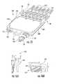
- FIGS. 24A and 24Billustrate more detail regarding the module rail guides 206 that are disposed in the fiber optic equipment 200 of FIGS. 22 and 23 .
- a module rail guide 206is disclosed that is provided between the first end 208 and the second end 210 .
- the channels 216are disposed on a first side 218 of the module rail guides 206 .
- Channels 220are also provided on a second side 224 of the module rail guides 206 .
- the module rail guide 206can support rails of fiber optic modules 204 on each side.
- 24Awould be provided as an intermediate module rail guide if more than one fiber optic module 204 in a given plane is supported by the fiber optic equipment 200 .
- at least one intermediate module rail guide 206is provided with channels 216 , 220 disposed on each side 218 , 224 .
- the module rail guide 206is attached to the chassis 202 such that when the module rails 215 A, 215 B of the fiber optic modules 204 are disposed within the channels 216 , 220 , the fiber optic modules 204 are supported by the chassis 202 . Also, as will be described in greater detail below with regard to FIGS.
- the module rail guides 206also contain a series of internal apertures 219 that support attaching module locks or stops to the chassis 202 .
- the module locks or stopsprevent the fiber optic modules 204 from translating beyond the front end 214 of the chassis 202 .
- FIG. 25illustrates the rear-installable fiber optic module 204 that is adapted to be supported by the module rail guides 206 of the fiber optic equipment 200 .
- module rails 215 A, 215 Bare disposed on sides 226 , 228 , respectively, of the fiber optic module 204 .
- These module rails 215 A, 215 Bcan be inserted into the module rail guides 206 to insert the fiber optic module 204 into the fiber optic equipment 200 .
- the channels 220 in the module rail guides 206are open in the rear section 212 of the chassis 202
- the fiber optic modules 204are rear-installable, meaning they can be installed from the rear section 212 of the chassis 202 .
- the fiber optic module 204contains a series of fiber optic adapters 230 disposed on a front end 232 of the fiber optic module 204 .
- One or more fiber optic adapters 230 optically connected to the fiber optic adapters 230are disposed on a rear end 234 of the fiber optic module 204 .
- connectorized fiber optic cables (not shown) connected to the fiber optic adapters 230establish a fiber optic connection with fiber optic cables (not shown) installed in the fiber optic adapters 230 in the rear end 234 of the fiber optic module 204 .
- FIG. 26Aillustrates a front view of the fiber optic equipment 200 with fiber optic modules 204 installed in the module rail guides 206 as previously described.
- stop or lock features 236are disposed between the rows of fiber optic modules 204 on the intermediate module rail guides 206 .
- FIG. 26Billustrates the stop or lock features 236 in more detail wherein front and rear perspective views are illustrated.
- the stop or lock features 236contain a series of apertures 238 that align with the apertures 219 disposed in the module rail guides 206 as illustrated previously in FIG. 24B .
- a fastener(not shown) can be inserted into the apertures 238 to fasten the stop or lock features 236 to the module rail guides 206 .
- the stop features 236contain opposing flared portions 240 on each side of the stop or lock feature 236 which contain platforms 242 of which the front end 232 of the fiber optic modules 204 abut against to prevent the fiber optic modules 204 from extending forward from the first end 208 of the chassis 202 .
- FIG. 27illustrates a top view of the fiber optic equipment 200 with the fiber optic module 204 installed therein between two module rail guides 206 .
- the fiber optic module 204is extended forward to the front end 214 of the chassis 202 wherein the front end 232 of the fiber optic module 204 abut against the platforms 242 in the stop or lock features 236 to prevent the fiber optic modules 204 from being extended beyond the front end 214 of the fiber optic equipment 200 .
- FIG. 28illustrates yet another embodiment of fiber optic equipment that is configured to allow and support rear-installable fiber optic modules.
- the fiber optic equipment 300contains a chassis 302 that supports one or more fiber optic modules 304 .
- the fiber optic modules 304are supported by a guide system in the form of module rail guides 306 that are attached to the chassis 302 such that each of the fiber optic modules 304 can translate about the module rail guides 306 .
- the fiber optic modules 304can be rear-installable from a rear section 308 of the chassis 302 into the module rail guides 306 and extended forward within the module rail guides 306 to a front end 310 of the chassis 302 .
- FIG. 29illustrates a rear perspective view of the fiber optic equipment 300 illustrated in FIG. 28 showing a series of rear-installable fiber optic modules 304 installed therein.
- the module rail guides 306can be provided that support more than one plane or row of fiber optic modules 304 . In such a case, a plurality of channels will be provided in the module rail guides 306 to support more than one row of fiber optic modules 304 .
- FIG. 30illustrates the fiber optic module 304 illustrated in FIGS. 28 and 29 in more detail.
- the fiber optic module 304contains module rails 312 A, 312 B disposed on each side 314 , 316 of the fiber optic module 304 .
- the module rails 312 A, 312 Bare adapted to be received into channels of the module rail guides 306 to support the fiber optic modules 304 .
- Each fiber optic module 304is independently movable about the module rail guides 306 . Intermediate fiber optic equipment trays are not provided.
- the fiber optic module 304contains a series of fiber optic adapters 318 disposed on a front end 320 of the fiber optic module 304 .
- a series of fiber optic connectors 322may be connected to the fiber optic adapters 318 to establish fiber optic connections.
- a fiber optic adapter 324is disposed in a rear end 326 of the fiber optic module 304 such that a fiber optic connector 322 connected to the fiber optic adapter 324 will establish an optical connection with optical fibers connected to the fiber optic connectors 322 .
- the fiber optic module 304also contains a series of pulling loops 328 A, 328 B disposed on each side of the fiber optic adapter 324 that may assist in removing the fiber optic module 304 from the rear section 308 of the fiber optic equipment 300 .
- hinged portions 330 A, 330 B of the rear section 308 of the chassis 302are pulled outward such that the module rail guides 306 are accessible to a technician. Thereafter, the fiber optic module 304 and its module rails 312 A, 312 B are inserted into channels in the module rail guides 306 as illustrated in FIG. 31 . The fiber optic module 304 is then pushed forward within the module rail guides 306 until the fiber optic module 304 reaches the front end 310 of the chassis 302 . Once the fiber optic modules 304 are installed as desired, the hinged portions 330 A, 330 B are closed.
- a module guide tray 332which is hingedly attached via hinges to the module rail guides 306 , can be pulled forward and tilted downward as illustrated in FIG. 32 .
- Each fiber optic module 304has its own module guide tray 332 such that each fiber optic module 304 is individually accessible and independently movable about the module rail guides 306 .
- the module guide tray 332may contain a series of fiber routing guides 336 that support routing of connectorized fiber optic cables (not shown) connected to the fiber optic adapters 318 of the fiber optic module 304 .
- FIG. 33illustrates a side perspective view illustrating more detail regarding the module guide tray 332 .
- the module guide tray 332is pulled forward and hingably tilted via hinge 334 downward to access the fiber optic adapters 318 of the fiber optic modules 304 .
- the module guide tray 332may contain a U-shaped flange 338 to allow optical fibers to be routed therein to either the left or right of the tray to the sides 340 , 342 of the chassis 302 .
- a handle 344may be provided and attached to the module guide tray 332 to allow for pulling and pushing for easy translation of the fiber optic module 304 .
- FIGS. 34 and 35illustrate yet another embodiment of fiber optic equipment 400 .
- a module guide systemis provided to allow fiber optic modules 402 to translate independently of each other about a chassis 404 outward in the Z-axis direction.
- two (2) fiber optic modules 402are provided.
- Each fiber optic module 402contains a series of fiber optic adapters 406 disposed in a front end 408 of the fiber optic module 402 .
- a module rail guide 410is disposed in the fiber optic equipment 400 for each fiber optic module 402 .
- two fiber optic modules 402are provided that expand the entire width of the chassis 404 . Thus, no intermediate module rail guides 410 are necessary or provided in the fiber optic equipment 400 .
- Each fiber optic module 402comprises a module rail 416 that is configured to be disposed within a channel 420 of the module rail guides 410 .
- the fiber optic modules 402may be rear-installable and may be independently movable from each other along their dedicated module rail 416 so they can be pulled out towards a front end 422 of the fiber optic equipment 400 and chassis 404 .
- FIGS. 34 and 35wherein the bottom fiber optic module 402 is pulled forward along its module rail 416 to provide access. After any access desired is completed, the bottom fiber optic module 402 can be pushed back in along its module rail 216 into the chassis 404 such that the front end 422 of the fiber optic module 402 will be disposed within the front end 408 of the chassis 404 .
Landscapes
- Physics & Mathematics (AREA)
- General Physics & Mathematics (AREA)
- Optics & Photonics (AREA)
- Light Guides In General And Applications Therefor (AREA)
- Mechanical Coupling Of Light Guides (AREA)
Abstract
Description
Claims (21)
Priority Applications (11)
| Application Number | Priority Date | Filing Date | Title |
|---|---|---|---|
| US12/323,423US8184938B2 (en) | 2008-08-29 | 2008-11-25 | Rear-installable fiber optic modules and equipment |
| EP09789091.7AEP2335108B1 (en) | 2008-08-29 | 2009-08-07 | Rear-installable fiber optic modules and equipment |
| CN201710264711.3ACN107367805B (en) | 2008-08-29 | 2009-08-07 | Rear-mountable fiber optic module and apparatus |
| ES09789091.7TES2613879T3 (en) | 2008-08-29 | 2009-08-07 | Fiber optic modules and equipment installed at the rear |
| CN200980134013.5ACN102138092B (en) | 2008-08-29 | 2009-08-07 | Rear-mountable fiber optic modules and devices |
| PCT/US2009/004549WO2010024847A2 (en) | 2008-08-29 | 2009-08-07 | Rear-installable fiber optic modules and equipment |
| EP16173431.4AEP3104205B1 (en) | 2008-08-29 | 2009-08-07 | Equipment for rear-installable fiber optic modules |
| CA2734718ACA2734718C (en) | 2008-08-29 | 2009-08-07 | Rear-installable fiber optic modules and equipment |
| AU2009286118AAU2009286118A1 (en) | 2008-08-29 | 2009-08-07 | Rear-installable fiber optic modules and equipment |
| JP2011524964AJP2012501467A (en) | 2008-08-29 | 2009-08-07 | Rear-mounting optical fiber module and equipment |
| JP2014231503AJP5967671B2 (en) | 2008-08-29 | 2014-11-14 | Rear-mounting optical fiber module and equipment |
Applications Claiming Priority (3)
| Application Number | Priority Date | Filing Date | Title |
|---|---|---|---|
| US19053808P | 2008-08-29 | 2008-08-29 | |
| US19706808P | 2008-10-23 | 2008-10-23 | |
| US12/323,423US8184938B2 (en) | 2008-08-29 | 2008-11-25 | Rear-installable fiber optic modules and equipment |
Publications (2)
| Publication Number | Publication Date |
|---|---|
| US20100054683A1 US20100054683A1 (en) | 2010-03-04 |
| US8184938B2true US8184938B2 (en) | 2012-05-22 |
Family
ID=41466804
Family Applications (1)
| Application Number | Title | Priority Date | Filing Date |
|---|---|---|---|
| US12/323,423Active2029-07-08US8184938B2 (en) | 2008-08-29 | 2008-11-25 | Rear-installable fiber optic modules and equipment |
Country Status (8)
| Country | Link |
|---|---|
| US (1) | US8184938B2 (en) |
| EP (2) | EP3104205B1 (en) |
| JP (2) | JP2012501467A (en) |
| CN (2) | CN102138092B (en) |
| AU (1) | AU2009286118A1 (en) |
| CA (1) | CA2734718C (en) |
| ES (1) | ES2613879T3 (en) |
| WO (1) | WO2010024847A2 (en) |
Cited By (60)
| Publication number | Priority date | Publication date | Assignee | Title |
|---|---|---|---|---|
| US20110129186A1 (en)* | 2009-11-30 | 2011-06-02 | Lewallen C Paul | Fiber Optic Module Assembly and Associated Methods |
| US20120314357A1 (en)* | 2011-06-10 | 2012-12-13 | Hon Hai Precision Industry Co., Ltd. | Server enclosure |
| US8731364B2 (en) | 2011-11-21 | 2014-05-20 | Ortronics, Inc. | Breakout assemblies and associated mounting members for fiber optic applications |
| US8879881B2 (en) | 2010-04-30 | 2014-11-04 | Corning Cable Systems Llc | Rotatable routing guide and assembly |
| US8913866B2 (en) | 2010-03-26 | 2014-12-16 | Corning Cable Systems Llc | Movable adapter panel |
| US8953924B2 (en) | 2011-09-02 | 2015-02-10 | Corning Cable Systems Llc | Removable strain relief brackets for securing fiber optic cables and/or optical fibers to fiber optic equipment, and related assemblies and methods |
| US8965168B2 (en) | 2010-04-30 | 2015-02-24 | Corning Cable Systems Llc | Fiber management devices for fiber optic housings, and related components and methods |
| US20150071597A1 (en)* | 2013-09-06 | 2015-03-12 | Corning Optical Communications LLC | Optical fiber cassette systems with fiber retaining covers |
| US8985862B2 (en) | 2013-02-28 | 2015-03-24 | Corning Cable Systems Llc | High-density multi-fiber adapter housings |
| US8989547B2 (en) | 2011-06-30 | 2015-03-24 | Corning Cable Systems Llc | Fiber optic equipment assemblies employing non-U-width-sized housings and related methods |
| US8995812B2 (en) | 2012-10-26 | 2015-03-31 | Ccs Technology, Inc. | Fiber optic management unit and fiber optic distribution device |
| US8992099B2 (en) | 2010-02-04 | 2015-03-31 | Corning Cable Systems Llc | Optical interface cards, assemblies, and related methods, suited for installation and use in antenna system equipment |
| US9008485B2 (en) | 2011-05-09 | 2015-04-14 | Corning Cable Systems Llc | Attachment mechanisms employed to attach a rear housing section to a fiber optic housing, and related assemblies and methods |
| US9020320B2 (en) | 2008-08-29 | 2015-04-28 | Corning Cable Systems Llc | High density and bandwidth fiber optic apparatuses and related equipment and methods |
| US9022814B2 (en) | 2010-04-16 | 2015-05-05 | Ccs Technology, Inc. | Sealing and strain relief device for data cables |
| US9038832B2 (en) | 2011-11-30 | 2015-05-26 | Corning Cable Systems Llc | Adapter panel support assembly |
| US9042702B2 (en) | 2012-09-18 | 2015-05-26 | Corning Cable Systems Llc | Platforms and systems for fiber optic cable attachment |
| US9075217B2 (en) | 2010-04-30 | 2015-07-07 | Corning Cable Systems Llc | Apparatuses and related components and methods for expanding capacity of fiber optic housings |
| US9116324B2 (en) | 2010-10-29 | 2015-08-25 | Corning Cable Systems Llc | Stacked fiber optic modules and fiber optic equipment configured to support stacked fiber optic modules |
| US9213161B2 (en) | 2010-11-05 | 2015-12-15 | Corning Cable Systems Llc | Fiber body holder and strain relief device |
| US20150370025A1 (en)* | 2014-06-23 | 2015-12-24 | Adc Telecommunications, Inc. | Bladed chassis systems |
| US9250409B2 (en) | 2012-07-02 | 2016-02-02 | Corning Cable Systems Llc | Fiber-optic-module trays and drawers for fiber-optic equipment |
| US9279951B2 (en) | 2010-10-27 | 2016-03-08 | Corning Cable Systems Llc | Fiber optic module for limited space applications having a partially sealed module sub-assembly |
| US20160085042A1 (en)* | 2014-09-24 | 2016-03-24 | Champion Optical Network Engineering, Llc | High-density modular wdm system - high density passive fiber module (pfm), tray and chassis interchangeable solution |
| US9488788B2 (en) | 2012-09-28 | 2016-11-08 | Commscope Technologies Llc | Fiber optic cassette |
| US9519118B2 (en) | 2010-04-30 | 2016-12-13 | Corning Optical Communications LLC | Removable fiber management sections for fiber optic housings, and related components and methods |
| EP3104205A2 (en) | 2008-08-29 | 2016-12-14 | Corning Optical Communications LLC | Rear-installable fiber optic modules and equipment |
| US9606318B2 (en) | 2014-06-17 | 2017-03-28 | Ortronics, Inc. | Cable management plate assembly and associated systems and methods |
| US20170090137A1 (en)* | 2015-09-24 | 2017-03-30 | Diversified Materials Specialists, Inc. | Fiber Optic Equipment Chassis And Modules |
| US9645317B2 (en) | 2011-02-02 | 2017-05-09 | Corning Optical Communications LLC | Optical backplane extension modules, and related assemblies suitable for establishing optical connections to information processing modules disposed in equipment racks |
| US9690065B2 (en) | 2014-09-12 | 2017-06-27 | Panduit Corp. | High density fiber enclosure and method |
| US9784936B2 (en) | 2014-06-17 | 2017-10-10 | Ortronics, Inc. | Media patching system with door assembly |
| USRE46780E1 (en) | 2009-06-08 | 2018-04-10 | Commscope, Inc. Of North Carolina | High density patching system for cable and optical fiber |
| US9997899B2 (en) | 2014-06-13 | 2018-06-12 | Ortronics, Inc. | Modular cable management spools |
| US10031295B2 (en) | 2011-09-12 | 2018-07-24 | Commscope Technologies Llc | Flexible lensed optical interconnect device for signal distribution |
| US10094996B2 (en) | 2008-08-29 | 2018-10-09 | Corning Optical Communications, Llc | Independently translatable modules and fiber optic equipment trays in fiber optic equipment |
| US10168502B2 (en) | 2017-01-12 | 2019-01-01 | Ortronics, Inc. | Fiber cassette and adapter module with slide lock |
| US10187706B2 (en) | 2016-07-12 | 2019-01-22 | Ortronics, Inc. | Snap clip fastener assembly |
| US10215944B2 (en) | 2016-06-30 | 2019-02-26 | Panduit Corp. | Modular fiber optic tray |
| EP3617762A1 (en) | 2018-08-31 | 2020-03-04 | Ortronics, Inc. | Detachable bezel for cassette mounting |
| US10606012B1 (en) | 2018-12-07 | 2020-03-31 | Ortronics, Inc. | Fiber optic cassette assembly |
| US10670822B2 (en) | 2017-06-28 | 2020-06-02 | Afl Telecommunications Llc | High density patch panel with modular cassettes |
| US10705306B2 (en) | 2016-09-08 | 2020-07-07 | CommScope Connectivity Belgium BVBA | Telecommunications distribution elements |
| US10859782B2 (en) | 2017-12-21 | 2020-12-08 | Ortronics, Inc. | Fiber enclosure |
| US11022770B2 (en) | 2015-07-29 | 2021-06-01 | Commscope Technologies Llc | Bladed chassis systems |
| US11175470B2 (en) | 2019-08-20 | 2021-11-16 | DMSI International | Enclosure assemblies for handling MDC connectors and associated cabling |
| EP3933472A1 (en) | 2020-07-01 | 2022-01-05 | Rosenberger Hochfrequenztechnik GmbH & Co. KG | Fiber optic module, fiber optic module kit, and optical patch panel |
| US11237348B2 (en) | 2019-04-17 | 2022-02-01 | Afl Ig Llc | Patch panel with lifting cassette removal |
| US11294136B2 (en) | 2008-08-29 | 2022-04-05 | Corning Optical Communications LLC | High density and bandwidth fiber optic apparatuses and related equipment and methods |
| US11369034B2 (en) | 2019-09-18 | 2022-06-21 | Ortronics, Inc. | Ejectable cassette, guide column, and ejectable cassette system |
| US11372186B2 (en) | 2017-04-04 | 2022-06-28 | Commscope Technologies Llc | Optical splice and termination module |
| US11409068B2 (en) | 2017-10-02 | 2022-08-09 | Commscope Technologies Llc | Fiber optic circuit and preparation method |
| US11467347B2 (en) | 2012-09-28 | 2022-10-11 | Commscope Connectivity Uk Limited | Manufacture and testing of fiber optic cassette |
| US11573389B2 (en) | 2012-10-05 | 2023-02-07 | Commscope Asia Holdings B.V. | Flexible optical circuit, cassettes, and methods |
| US20230073414A1 (en)* | 2021-09-03 | 2023-03-09 | Panduit Corp. | High density fiber cassette and enclosure |
| US11686912B1 (en) | 2020-08-06 | 2023-06-27 | DMSI International | Optical fiber assemblies for accommodating mini duplex connectors |
| US11971600B2 (en) | 2020-06-12 | 2024-04-30 | viaPhoton, Inc. | Fiber organizer |
| US12075592B2 (en) | 2022-06-02 | 2024-08-27 | Legrand DPC, LLC | Modular cable management device |
| US12298574B2 (en) | 2020-08-20 | 2025-05-13 | viaPhoton, Inc. | Optical fiber management system |
| US12339511B2 (en) | 2020-03-31 | 2025-06-24 | Commscope Technologies Llc | Fiber optic cable management systems and methods |
Families Citing this family (24)
| Publication number | Priority date | Publication date | Assignee | Title |
|---|---|---|---|---|
| US11251608B2 (en) | 2010-07-13 | 2022-02-15 | Raycap S.A. | Overvoltage protection system for wireless communication systems |
| WO2012068013A2 (en)* | 2010-11-15 | 2012-05-24 | Adc Telecommunications, Inc. | Cable management in rack systems |
| US9383537B2 (en) | 2013-08-28 | 2016-07-05 | Corning Optical Communications LLC | Cassette and drop handle with flexible radius controller |
| CN105705976A (en)* | 2013-09-23 | 2016-06-22 | 泰科电子英国有限公司 | Telecommunications chassis |
| WO2016012295A1 (en) | 2014-07-22 | 2016-01-28 | Tyco Electronics Raychem Bvba | Door hinge mechanism for telecommunicatons panel |
| EP3192274A4 (en) | 2014-09-11 | 2018-05-16 | ADC Telecommunications, Inc. | Door hinge mechanism for telecommunications panel |
| WO2016168337A1 (en) | 2015-04-13 | 2016-10-20 | Commscope Technologies Llc | Telecommunications chassis and module |
| CH710988A1 (en)* | 2015-04-22 | 2016-10-31 | Bks Eng Ag | Stop system for electrical unit. |
| EP3286588B1 (en)* | 2015-04-23 | 2020-01-29 | CommScope Connectivity Belgium BVBA | Telecommunications panel assembly with movable adapters |
| US10802237B2 (en) | 2015-11-03 | 2020-10-13 | Raycap S.A. | Fiber optic cable management system |
| US9971119B2 (en) | 2015-11-03 | 2018-05-15 | Raycap Intellectual Property Ltd. | Modular fiber optic cable splitter |
| US10585258B2 (en) | 2015-11-10 | 2020-03-10 | Commscope Technologies Llc | Bladed chassis systems and removable cassettes |
| WO2017184501A1 (en) | 2016-04-19 | 2017-10-26 | Commscope, Inc. Of North Carolina | Door assembly for a telecommunications chassis with a combination hinge structure |
| ES2851948T3 (en) | 2016-04-19 | 2021-09-09 | Commscope Inc North Carolina | Telecom rack with slide out trays |
| WO2018136812A1 (en) | 2017-01-20 | 2018-07-26 | Raycap S.A. | Power transmission system for wireless communication systems |
| DE102018106262A1 (en) | 2018-03-17 | 2019-09-19 | Zellner Gmbh | Slide-in module system with front release |
| US10971928B2 (en) | 2018-08-28 | 2021-04-06 | Raycap Ip Assets Ltd | Integrated overvoltage protection and monitoring system |
| CN109375324A (en)* | 2018-10-23 | 2019-02-22 | 浙江舟电子科技股份有限公司 | A kind of pre-terminated high-density optical-fiber distribution frame |
| CN110673282A (en)* | 2019-09-25 | 2020-01-10 | 深圳长飞智连技术有限公司 | Ultrahigh-density modular optical fiber distribution frame system |
| US11677164B2 (en) | 2019-09-25 | 2023-06-13 | Raycap Ip Assets Ltd | Hybrid antenna distribution unit |
| JP7457206B2 (en)* | 2021-04-23 | 2024-03-27 | 株式会社フジクラ | optical termination box |
| EP4388356A1 (en)* | 2021-08-20 | 2024-06-26 | Viaphoton, Inc. | Optical fiber management system |
| US12237134B2 (en) | 2021-12-28 | 2025-02-25 | Raycap Ip Assets Ltd | Circuit protection for hybrid antenna distribution units |
| EP4350409B1 (en)* | 2022-10-07 | 2024-07-24 | Rosenberger-OSI GmbH & Co. OHG | Module assembly, support unit and support assembly for optical fibre distribution technology |
Citations (191)
| Publication number | Priority date | Publication date | Assignee | Title |
|---|---|---|---|---|
| US620013A (en) | 1899-02-21 | Medicine-case | ||
| US3175873A (en) | 1961-06-09 | 1965-03-30 | Fmc Corp | Panel locking mechanism for console type structures |
| US4792203A (en) | 1985-09-17 | 1988-12-20 | Adc Telecommunications, Inc. | Optical fiber distribution apparatus |
| US4798432A (en) | 1985-09-11 | 1989-01-17 | U.S. Philips Corp. | Storage container for a section of a light conducting fibre |
| US4824196A (en) | 1987-05-26 | 1989-04-25 | Minnesota Mining And Manufacturing Company | Optical fiber distribution panel |
| US4898448A (en) | 1988-05-02 | 1990-02-06 | Gte Products Corporation | Fiber distribution panel |
| US4971421A (en) | 1989-09-29 | 1990-11-20 | Reliance Comm/Tec Corporation | Fiber optic splice and patch enclosure |
| US5001602A (en) | 1988-11-28 | 1991-03-19 | Reliance Comm/Tec Corporation | Network interface cabinet for large pair count telephone terminations |
| WO1991005281A1 (en) | 1989-09-29 | 1991-04-18 | Northern Telecom Limited | Connector holders and distribution frame and connector holder assemblies for optical cable |
| JPH03172806A (en) | 1989-12-01 | 1991-07-26 | Nippon Telegr & Teleph Corp <Ntt> | Optical connector |
| GB2241591A (en) | 1990-02-28 | 1991-09-04 | Optical Data Communications Li | Mounting frames for fibre optic or electrical cable organiser trays |
| US5066149A (en) | 1990-09-11 | 1991-11-19 | Adc Telecommunications, Inc. | Splice tray with slack take-up |
| US5067784A (en) | 1990-11-19 | 1991-11-26 | George Debortoli | Connector holders |
| US5071211A (en) | 1988-12-20 | 1991-12-10 | Northern Telecom Limited | Connector holders and distribution frame and connector holder assemblies for optical cable |
| US5080459A (en) | 1987-12-23 | 1992-01-14 | British Telecommunications Public Limited Company | Mounting assembly for optical equipment |
| DE4030301A1 (en) | 1990-09-25 | 1992-03-26 | Siemens Ag | DISTRIBUTION DEVICE FOR LIGHTWAVE GUIDE |
| US5100221A (en) | 1990-01-22 | 1992-03-31 | Porta Systems Corp. | Optical fiber cable distribution frame and support |
| US5127082A (en) | 1991-03-22 | 1992-06-30 | The Siemon Company | Fiber optic patch panel |
| US5133039A (en) | 1990-10-29 | 1992-07-21 | At&T Bell Laboratories | Aerial fiber optic cable case |
| US5138688A (en) | 1990-11-09 | 1992-08-11 | Northern Telecom Limited | Optical connector holder assembly |
| US5142607A (en) | 1990-03-20 | 1992-08-25 | Rittal-Werk Rudolf Loh Gmbh & Co. Kg | Splice box for optical wave guide |
| US5150277A (en) | 1990-05-04 | 1992-09-22 | At&T Bell Laboratories | Cooling of electronic equipment cabinets |
| US5167001A (en) | 1991-09-03 | 1992-11-24 | Northern Telecom Limited | Optical fiber storage and connector tray and shelf and tray assembly |
| US5231687A (en) | 1990-06-04 | 1993-07-27 | Bicc Plc | Termination system for optical fibres |
| US5253320A (en) | 1991-11-29 | 1993-10-12 | Fujitsu Limited | Optical fiber cable lead-in structure |
| US5265187A (en) | 1992-10-28 | 1993-11-23 | Northern Telecom Limited | Distribution frame and optical connector holder combination |
| US5274731A (en) | 1992-12-24 | 1993-12-28 | Adc Telecommunications, Inc. | Optical fiber cabinet |
| US5285515A (en) | 1992-02-21 | 1994-02-08 | Mars Actel | Adaptable cassette for coiling and splicing optical fibers |
| US5323478A (en) | 1992-02-21 | 1994-06-21 | Mars Actel | Assembly of stacked and hinged modules |
| US5339379A (en) | 1993-06-18 | 1994-08-16 | Telect, Inc. | Telecommunication fiber optic cable distribution apparatus |
| US5363466A (en) | 1992-02-21 | 1994-11-08 | Mars Actel | Assembly of hinged flat modules |
| US5412751A (en) | 1993-08-31 | 1995-05-02 | The Siemon Company | Retrofittable multimedia patch management system |
| US5442725A (en) | 1993-08-30 | 1995-08-15 | At&T Corp. | Pivotally mounted tray for organizing optical fibers |
| US5497444A (en) | 1994-01-21 | 1996-03-05 | Adc Telecommunications, Inc. | High-density fiber distribution frame |
| US5511144A (en) | 1994-06-13 | 1996-04-23 | Siecor Corporation | Optical distribution frame |
| US5519804A (en) | 1994-06-22 | 1996-05-21 | At&T Corp. | Universal splice tray |
| US5572617A (en) | 1994-04-26 | 1996-11-05 | Krone Aktiengesellschaft | Housing for optical components |
| US5577151A (en) | 1995-08-15 | 1996-11-19 | The Whitaker Corporation | Optical fiber splice tray and cover |
| US5613030A (en) | 1995-05-15 | 1997-03-18 | The Whitaker Corporation | High density fiber optic interconnection enclosure |
| CH688705A5 (en) | 1997-04-16 | 1998-01-15 | Alsthom Cge Alcatel | Cover for protecting optical fibre cable distributor in slide-in tray from mechanical damage |
| CA2029592C (en) | 1990-11-08 | 1998-03-31 | George Debortoli | Optical connector holder assembly |
| US5740300A (en) | 1996-05-01 | 1998-04-14 | Scientific-Atlanta, Inc. | Transceiver module support apparatus with fiber management features |
| JPH10227919A (en) | 1997-02-14 | 1998-08-25 | Fujikura Ltd | Optical distribution frame and optical branch module |
| US5835657A (en) | 1995-12-08 | 1998-11-10 | Psi Telecommunications, Inc. | Fiber optic splice tray |
| JPH10339817A (en) | 1997-06-09 | 1998-12-22 | Kansai Electric Power Co Inc:The | Optical wiring board and tray unit therefor |
| JPH1123858A (en) | 1997-07-08 | 1999-01-29 | Tokyo Electric Power Co Inc:The | Cable wiring equipment |
| US5887106A (en) | 1996-04-12 | 1999-03-23 | Telephone Cables Limited | Management of optical fiber |
| US5894540A (en) | 1997-05-22 | 1999-04-13 | Lucent Technologies Inc. | Optical Fiber take-up assembly |
| US5946440A (en) | 1997-11-17 | 1999-08-31 | Adc Telecommunications, Inc. | Optical fiber cable management device |
| US5945633A (en) | 1996-05-23 | 1999-08-31 | The Siemon Company | Rack mountable cable distribution enclosure having an angled adapter plate bracket |
| US5966492A (en) | 1997-12-19 | 1999-10-12 | Antec Corporation | Apparatus for storing and splicing optical fibers |
| US5978540A (en) | 1998-04-23 | 1999-11-02 | Antec Corporation | Apparatus for interconnecting optical fibers |
| US5975769A (en) | 1997-07-08 | 1999-11-02 | Telect, Inc. | Universal fiber optic module system |
| US6009224A (en) | 1997-11-06 | 1999-12-28 | Allen; Barry Wayne | Fiber optic organizer with lockable trays and method of accessing a tray |
| JP2000098139A (en) | 1998-09-18 | 2000-04-07 | Sumitomo Electric Ind Ltd | Light termination |
| JP2000098138A (en) | 1998-09-18 | 2000-04-07 | Sumitomo Electric Ind Ltd | Light termination |
| US6058235A (en) | 1998-06-23 | 2000-05-02 | Fujitsu Limited | Line terminating device |
| JP2001004849A (en) | 1999-04-22 | 2001-01-12 | Fujikura Ltd | Optical distribution frame |
| US6215938B1 (en) | 1998-09-21 | 2001-04-10 | Adc Telecommunications, Inc. | Fiber optic cabinet and tray |
| JP3160322B2 (en) | 1991-08-14 | 2001-04-25 | 日本電信電話株式会社 | Optical connector structure |
| JP2001133636A (en) | 1999-11-09 | 2001-05-18 | Fujikura Ltd | Optical module storage unit |
| JP3173962B2 (en) | 1995-03-13 | 2001-06-04 | 株式会社フジクラ | Optical distribution frame |
| JP2001154030A (en) | 1999-11-26 | 2001-06-08 | Fujikura Ltd | Optical wiring unit |
| JP2001159714A (en) | 1999-12-03 | 2001-06-12 | Furukawa Electric Co Ltd:The | Optical fiber extra length storage device |
| US6263141B1 (en) | 1998-09-09 | 2001-07-17 | Adc Telecommunications, Inc. | Optical fiber cable management device including storage tray |
| US6301424B1 (en) | 2000-04-13 | 2001-10-09 | Lucent Technologies Inc. | Distribution frame cable routing apparatus |
| US6322279B1 (en) | 1997-11-04 | 2001-11-27 | Sports Carriers, Inc. | Adjustable attachment device |
| JP2002022974A (en) | 2000-07-05 | 2002-01-23 | Fujikura Ltd | Optical distribution frame and optical module |
| US6370309B1 (en) | 1999-07-30 | 2002-04-09 | Lucent Technologies, Inc. | Splice holder with a self-mounting feature |
| JP3279474B2 (en) | 1996-03-21 | 2002-04-30 | 株式会社フジクラ | Optical branch module |
| WO2002042818A1 (en) | 2000-11-21 | 2002-05-30 | Euromicron Werkzeuge Gmbh | Connector for optical waveguides comprising a connector housing |
| JP2002169035A (en) | 2000-12-05 | 2002-06-14 | Japan Recom Ltd | Cabinet for storing cable connections |
| US6427045B1 (en) | 2000-03-08 | 2002-07-30 | Marconi Communications, Inc. | Splice tray for use in splicing fiber optic cables and housing therefor |
| US6438310B1 (en) | 2000-01-24 | 2002-08-20 | Adc Telecommunications, Inc. | Cable management panel with sliding drawer |
| US6456773B1 (en) | 1999-04-26 | 2002-09-24 | Ciena Corporation | Dispersion compensation module |
| JP2002305389A (en) | 2001-04-06 | 2002-10-18 | Fujitsu Ltd | Transmission equipment |
| US6484958B1 (en) | 2001-11-20 | 2002-11-26 | Dowslake Microsystems Corporation | Patch cord caddy |
| US20020181922A1 (en) | 2001-06-01 | 2002-12-05 | Xin Xin | High density fiber optic splitter/connector tray system |
| US6504988B1 (en) | 2000-01-24 | 2003-01-07 | Adc Telecommunications, Inc. | Cable management panel with sliding drawer |
| US6507980B2 (en) | 2000-08-21 | 2003-01-21 | Abus August Bremicker Sohne Kg | Holder |
| JP2003029054A (en) | 2001-07-18 | 2003-01-29 | Nec Corp | Optical fiber cord surplus processing device, and optical fiber cable storage device incorporated with the same |
| JP3403573B2 (en) | 1996-03-21 | 2003-05-06 | 株式会社フジクラ | Optical branch module |
| JP2003169026A (en) | 2001-12-03 | 2003-06-13 | Mitsubishi Electric Corp | Optical communication package |
| US6600866B2 (en) | 2001-03-13 | 2003-07-29 | 3M Innovative Properties Company | Filament organizer |
| JP2003215353A (en) | 2002-01-28 | 2003-07-30 | Fujikura Ltd | Optical module |
| US6647197B1 (en) | 2000-06-02 | 2003-11-11 | Panduit Corp. | Modular latch and guide rail arrangement for use in fiber optic cable management systems |
| JP2003344701A (en) | 2002-05-22 | 2003-12-03 | Yazaki Corp | Optical connector |
| US6677520B1 (en) | 2002-07-22 | 2004-01-13 | Adc Telecommunications, Inc. | Fanning tray |
| JP3487946B2 (en) | 1995-03-15 | 2004-01-19 | 株式会社フジクラ | Optical distribution frame |
| JP3516765B2 (en) | 1995-03-08 | 2004-04-05 | 株式会社フジクラ | Optical distribution frame |
| US6715619B2 (en) | 2002-07-22 | 2004-04-06 | Adc Telecommunications, Inc. | Fiber management drawer and patch panel |
| US6719149B2 (en) | 2001-09-04 | 2004-04-13 | Allied Telesis Kabushiki Kaisha | Accommodation apparatus for communication devices |
| JP2004514931A (en) | 2000-11-21 | 2004-05-20 | オイロミクロン・ベルクツォイゲ・ゲゼルシャフト・ミット・ベシュレンクテル・ハフツング | Connector for optical waveguide with connector housing |
| JP2004144808A (en) | 2002-10-22 | 2004-05-20 | Nippon Tsushin Denzai Kk | Optical junction box |
| US6741785B2 (en) | 2002-04-19 | 2004-05-25 | Plexus Corporation | Optical fiber management system and method |
| US6748154B2 (en) | 2002-03-28 | 2004-06-08 | Nortel Networks Limited | Optical module access tray |
| US6748155B2 (en) | 2002-07-22 | 2004-06-08 | Adc Telecommunications, Inc. | Fiber management drawer and sliding cable slack limiter |
| WO2004052066A1 (en) | 2002-11-29 | 2004-06-17 | Fujitsu Limited | Unit mounted on electronic device and connection mechanism of transmission line of the electronic device |
| US6768860B2 (en) | 2002-12-05 | 2004-07-27 | Jds Uniphase Inc. | High density fiber optic module |
| JP2004246147A (en) | 2003-02-14 | 2004-09-02 | Fujikura Ltd | Optical connection unit |
| US6788871B2 (en) | 2000-09-27 | 2004-09-07 | Krone Gmbh | Optical fiber connection housing with an outlet connector element and a splice connection to an optical line group |
| US20040175090A1 (en) | 2001-04-02 | 2004-09-09 | Kristof Vastmans | Optical fibre organiser |
| US6804447B2 (en) | 2002-11-05 | 2004-10-12 | Adc Telecommunications, Inc. | Fiber panel with integrated couplers |
| JP2004361652A (en) | 2003-06-04 | 2004-12-24 | Fujikura Ltd | Optical fiber connection unit and optical module |
| JP2004361893A (en) | 2003-06-09 | 2004-12-24 | Kawamura Electric Inc | Splicing unit |
| US6840815B2 (en) | 2001-09-28 | 2005-01-11 | Adc Telecommunications, Inc. | Front access DSX assembly |
| JP3107704U (en) | 2004-09-13 | 2005-02-03 | 株式会社昭電 | cabinet |
| JP2005055748A (en) | 2003-08-06 | 2005-03-03 | Nippon Tsushin Denzai Kk | Optical connection box |
| US6865331B2 (en) | 2003-01-15 | 2005-03-08 | Adc Telecommunications, Inc. | Rotating radius limiter for cable management panel and methods |
| JP2005062569A (en) | 2003-08-15 | 2005-03-10 | Fujitsu Ltd | Optical fiber cable wiring accommodation structure, optical connector accommodation case, optical connector accommodation method, and optical connector connection method |
| US6870734B2 (en) | 2003-05-30 | 2005-03-22 | Adc Telecommunications, Inc. | Fiber containment system |
| JP2005084241A (en) | 2003-09-05 | 2005-03-31 | Mitsubishi Cable Ind Ltd | Optical fiber connection box |
| US6920274B2 (en) | 2003-12-23 | 2005-07-19 | Adc Telecommunications, Inc. | High density optical fiber distribution frame with modules |
| US6925241B2 (en) | 2002-10-11 | 2005-08-02 | 3M Innovative Properties Company | Drawer for the management of optical fibers |
| US6937807B2 (en) | 2002-04-24 | 2005-08-30 | Adc Telecommunications, Inc. | Cable management panel with sliding drawer |
| US6944389B2 (en)* | 2003-11-26 | 2005-09-13 | Corning Cable Systems Llc | Connector housing having a sliding tray with a hingeable portion |
| US6944383B1 (en) | 2004-04-12 | 2005-09-13 | Adc Telecommunications, Inc. | Cable management panel with sliding drawer and methods |
| US20060018622A1 (en) | 2004-07-22 | 2006-01-26 | Caveney Jack E | Front access punch down patch panel |
| US6993237B2 (en) | 2003-11-26 | 2006-01-31 | Corning Cable Systems Llc | Pulling grip for installing pre-connectorized fiber optic cable |
| US7031588B2 (en) | 2004-04-27 | 2006-04-18 | Commscope Solutions Properties, Llc | Articulated high density fiber optic splice and termination shelf |
| JP2006126516A (en) | 2004-10-28 | 2006-05-18 | Fujikura Ltd | Optical distribution board |
| JP2006126513A (en) | 2004-10-28 | 2006-05-18 | Fujikura Ltd | Alignment element, alignment board, optical distribution board |
| US7068907B2 (en) | 2001-02-12 | 2006-06-27 | Fiber Optic Network Solutions, Corp. | Optical fiber enclosure system |
| US7079744B2 (en) | 2001-07-06 | 2006-07-18 | Adc Telecommunications, Inc. | Cable management panel with sliding drawer and methods |
| JP2006227041A (en) | 2005-02-15 | 2006-08-31 | Osaki Electric Co Ltd | Optical fiber storage tray drawing position lock structure, optical fiber storage unit, and optical distribution board |
| US7101093B2 (en) | 2004-08-06 | 2006-09-05 | Industrial Technology Research | Extending latch mechanism for a pluggable optical module |
| US20060198098A1 (en) | 2005-03-02 | 2006-09-07 | Adc Telecommunications, Inc. | Patch panel chassis |
| US7113686B2 (en) | 2002-04-12 | 2006-09-26 | Tyco Electronics Raychem Nv | Optical circuit enclosure |
| US7113687B2 (en) | 2004-05-06 | 2006-09-26 | Commscope Solutions Properties Llc | Carrier for multiple splice trays |
| US7116883B2 (en) | 2004-11-19 | 2006-10-03 | Fiber Optic Protection Systems, Inc. | Fiber optic protective carrier |
| US7118281B2 (en) | 2002-08-09 | 2006-10-10 | Jds Uniphase Corporation | Retention and release mechanisms for fiber optic modules |
| US7171099B2 (en) | 2003-07-31 | 2007-01-30 | Adc Telecommunications, Inc. | Slide arrangement for cable drawer |
| JP2007067458A (en) | 2005-08-29 | 2007-03-15 | Chugoku Electric Power Co Inc:The | Distribution optical coupler module and coupler module storage rack |
| US7200316B2 (en) | 2003-11-26 | 2007-04-03 | Corning Cable Systems Llc | Connector housing for a communication network |
| US7236677B2 (en) | 2004-11-24 | 2007-06-26 | Corning Cable Systems Llc | Optical fiber distribution apparatus |
| US7245809B1 (en) | 2005-12-28 | 2007-07-17 | Adc Telecommunications, Inc. | Splitter modules for fiber distribution hubs |
| US7259325B2 (en) | 2004-03-15 | 2007-08-21 | Powerdsine, Ltd.-Microsemi Corporation | High density front access device |
| US7272291B2 (en) | 2005-08-25 | 2007-09-18 | Adc Telecommunications, Inc. | Splice chip device |
| US7274852B1 (en) | 2005-12-02 | 2007-09-25 | Adc Telecommunications, Inc. | Splice tray arrangement |
| US7298950B2 (en) | 2003-09-17 | 2007-11-20 | Corning Cable Systems Llc | Distribution cabinet for optical fibers |
| US7302149B2 (en) | 2004-09-09 | 2007-11-27 | Adc Telecommunications, Inc. | WDM systems and methods |
| US20080025683A1 (en) | 2006-07-26 | 2008-01-31 | Adam Murano | Secure fiber optic network cassette assembly |
| US7325975B2 (en) | 2003-05-16 | 2008-02-05 | Nec Corporation | Optical module with lever that abuts case to release latch from locking state with cage which accommodates optical module |
| US7330626B2 (en) | 2005-08-31 | 2008-02-12 | Adc Telecommunications, Inc. | Cabinet including optical bulkhead plate for blown fiber system |
| US7340145B2 (en) | 2005-10-24 | 2008-03-04 | Tyco Electronics Corporation | Fiber optic splice storage apparatus and methods for using the same |
| US20080068788A1 (en) | 2005-05-31 | 2008-03-20 | Fujio Ozawa | Communication apparatus, information processing device, and external cable connection method |
| US7349615B2 (en) | 2006-08-25 | 2008-03-25 | Corning Cable Systems Llc | Fiber optic housing assembly for fiber optic connections comprising pivotable portion |
| US20080080827A1 (en) | 2006-10-02 | 2008-04-03 | Eduardo Leon | Universal splitter module holder for an optic fiber distribution hub |
| US20080080826A1 (en) | 2006-10-02 | 2008-04-03 | Eduardo Leon | Distribution module for an optic fiber distribution hub |
| US20080080828A1 (en) | 2006-10-02 | 2008-04-03 | Eduardo Leon | Slack limiting fiber management system for an optic fiber distribution hub |
| US20080089656A1 (en) | 2006-10-11 | 2008-04-17 | Panduit Corp. | Release Latch for Pre-Terminated Cassette |
| US7376323B2 (en) | 2005-05-25 | 2008-05-20 | Adc Telecommunications, Inc. | Fiber optic adapter module |
| US20080118207A1 (en) | 2005-01-24 | 2008-05-22 | Sumitomo Electric Industries, Ltd. | Optical Fiber Module |
| US7391952B1 (en) | 2006-08-31 | 2008-06-24 | Corning Cable Systems Llc | Pre-connectorized fiber optic cable network interconnection apparatus |
| US20080152294A1 (en) | 2006-10-26 | 2008-06-26 | Sumitomo Electric Industries, Ltd. | Container for accommodating optical fiber coil and optical fiber module having the container |
| US7397996B2 (en) | 2005-08-02 | 2008-07-08 | Adc Telecommunications, Inc. | Cable management panel with rear entry |
| US7400813B2 (en) | 2005-05-25 | 2008-07-15 | Adc Telecommunications, Inc. | Fiber optic splitter module |
| US20080175552A1 (en) | 2007-01-19 | 2008-07-24 | Mark Smrha | Adapter panel with lateral sliding adapter arrays |
| US20080175551A1 (en) | 2007-01-19 | 2008-07-24 | Mark Smrha | Adapter panel with lateral sliding adapter arrays |
| JP2008176118A (en) | 2007-01-19 | 2008-07-31 | Kawamura Electric Inc | Optical path device |
| US7409137B2 (en) | 2006-10-04 | 2008-08-05 | Adc Telecommunications, Inc. | Slide arrangement for cable drawer |
| JP2008180817A (en) | 2007-01-23 | 2008-08-07 | Hata Kensaku:Kk | Optical branch connection device |
| US7418184B1 (en) | 2007-03-15 | 2008-08-26 | Curtis Paul Gonzales | Fiber optic categorization and management tray |
| US7418182B2 (en) | 2006-10-10 | 2008-08-26 | Adc Telecommunications, Inc. | Cable management drawer with access panel |
| US20080205844A1 (en) | 2007-02-28 | 2008-08-28 | Guy Castonguay | Fiber optic splice trays |
| US20080219632A1 (en) | 2007-03-09 | 2008-09-11 | Smith Trevor D | Telecommunication rack unit tray |
| US7437049B2 (en) | 2006-10-10 | 2008-10-14 | Adc Telecommunications, Inc. | Cable management drawer with access panel |
| US7439453B2 (en) | 2006-05-09 | 2008-10-21 | Ortronics, Inc. | Hinge system for low-profile cabinet assemblies |
| US20080292261A1 (en) | 2007-05-07 | 2008-11-27 | Kowalczyk Scott C | Fiber optic enclosure with external cable spool |
| US7460758B2 (en) | 2005-06-03 | 2008-12-02 | Telect Inc. | Fiber management system |
| US20080310810A1 (en) | 2007-06-17 | 2008-12-18 | Telect, Inc. | Expandable fiber management |
| JP2009503582A (en) | 2005-07-26 | 2009-01-29 | エーディーシー テレコミュニケーションズ,インコーポレイティド | Fiber optic connector holder |
| US7493002B2 (en) | 2007-01-19 | 2009-02-17 | Adc Telecommunications, Inc. | Fiber optic adapter cassette and panel |
| US7499622B2 (en) | 2007-02-28 | 2009-03-03 | Corning Cable Systems Llc | Fiber optic drop terminals for multiple dwelling units |
| US20090060439A1 (en) | 2007-09-05 | 2009-03-05 | Terry Dean Cox | Fiber optic terminal assembly |
| US20090067800A1 (en)* | 2007-09-07 | 2009-03-12 | Mariano Perez Vazquez | Fiber optic adapter module and tray |
| US20090097813A1 (en) | 2007-10-01 | 2009-04-16 | John Paul Hill | Modular optical fiber cassettes and fiber management methods |
| US7567744B2 (en) | 2007-06-06 | 2009-07-28 | Adc Telecommunications, Inc. | Rear drawer latch |
| US7577331B2 (en) | 2003-04-16 | 2009-08-18 | Adc Gmbh | Optical fiber coupler module |
| US20090220204A1 (en) | 2008-02-28 | 2009-09-03 | Gil Ruiz | Splice revolver, splice module and method of organizing fiber strands in the splice module |
| US20090245743A1 (en) | 2008-03-27 | 2009-10-01 | Cote Monique L | Compact, high-density adapter module, housing assembly and frame assembly for optical fiber telecommunications |
| US20090252472A1 (en) | 2008-02-15 | 2009-10-08 | Adc Telecommunications, Inc. | Fiber Optic Splice Enclosure |
| US20090290842A1 (en) | 2008-04-21 | 2009-11-26 | Bran De Leon Oscar Fernando | Fiber optic splice tray |
| US20090304342A1 (en) | 2008-06-09 | 2009-12-10 | Adc Gmbh | Terminal box for fiberoptic cables and panel |
| US20090324189A1 (en) | 2007-10-01 | 2009-12-31 | Clearfield, Inc. | Modular optical fiber cassette |
| US20100054682A1 (en)* | 2008-08-29 | 2010-03-04 | Cooke Terry L | Independently Translatable Modules and Fiber Optic Equipment Trays in Fiber Optic Equipment |
| US20100054685A1 (en) | 2008-08-29 | 2010-03-04 | Cooke Terry L | Telescoping Fiber Optic Module and Related Equipment |
| US20100061693A1 (en) | 2008-09-09 | 2010-03-11 | Bran De Leon Oscar Fernando | Fiber Optic Splice Tray |
| US20100074587A1 (en) | 2008-09-16 | 2010-03-25 | Todd Loeffelholz | Modular fiber optic enclosure with external cable spool |
| US20100086274A1 (en) | 2008-10-07 | 2010-04-08 | Scott Martin Keith | Telecommunications Patching Systems with Vertically-Oriented Patching Modules |
| US7853112B2 (en)* | 2006-02-13 | 2010-12-14 | Adc Telecommunications, Inc. | Fiber optic splitter module |
Family Cites Families (13)
| Publication number | Priority date | Publication date | Assignee | Title |
|---|---|---|---|---|
| EP0530325B1 (en) | 1990-05-21 | 1997-03-05 | Minnesota Mining And Manufacturing Company | Optical fiber distribution center |
| DE4112871A1 (en)* | 1991-04-19 | 1992-10-22 | Oberspree Habelwerk Gmbh | Holder for optical fibre splice and storage cassettes - accepts stack of cassettes slid into parallel grooves and retained by trapezoidal heads of resilient catches |
| JPH09178998A (en)* | 1995-12-21 | 1997-07-11 | Fujitsu Ltd | Optical adapter unit |
| JPH09197139A (en)* | 1996-01-18 | 1997-07-31 | Sumitomo Electric Ind Ltd | Optical cable connection module |
| US5701380A (en)* | 1996-06-24 | 1997-12-23 | Telect, Inc. | Fiber optic module for high density supply of patching and splicing |
| US6049709A (en)* | 1996-12-06 | 2000-04-11 | Adc Telecommunications, Inc. | RF circuit module |
| US6208796B1 (en)* | 1998-07-21 | 2001-03-27 | Adc Telecommunications, Inc. | Fiber optic module |
| JP2004086060A (en)* | 2002-08-28 | 2004-03-18 | Nippon Tsushin Denzai Kk | Optical module and optical termination box |
| JP4159977B2 (en)* | 2003-12-18 | 2008-10-01 | 株式会社フジクラ | Optical module |
| JP4237079B2 (en)* | 2004-02-27 | 2009-03-11 | 株式会社フジクラ | Optical fiber cable connection method |
| US7376321B2 (en)* | 2004-08-09 | 2008-05-20 | Adc Telecommunications, Inc. | Modules including multiple rows of adapters for high density optical fiber distribution frame |
| KR100699907B1 (en) | 2005-04-25 | 2007-03-27 | 주식회사 케이티엔티 | Optical distribution box for high speed information and communication building |
| US8184938B2 (en) | 2008-08-29 | 2012-05-22 | Corning Cable Systems Llc | Rear-installable fiber optic modules and equipment |
- 2008
- 2008-11-25USUS12/323,423patent/US8184938B2/enactiveActive
- 2009
- 2009-08-07CNCN200980134013.5Apatent/CN102138092B/enactiveActive
- 2009-08-07ESES09789091.7Tpatent/ES2613879T3/enactiveActive
- 2009-08-07EPEP16173431.4Apatent/EP3104205B1/enactiveActive
- 2009-08-07WOPCT/US2009/004549patent/WO2010024847A2/enactiveApplication Filing
- 2009-08-07AUAU2009286118Apatent/AU2009286118A1/ennot_activeAbandoned
- 2009-08-07CNCN201710264711.3Apatent/CN107367805B/enactiveActive
- 2009-08-07CACA2734718Apatent/CA2734718C/enactiveActive
- 2009-08-07JPJP2011524964Apatent/JP2012501467A/enactivePending
- 2009-08-07EPEP09789091.7Apatent/EP2335108B1/enactiveActive
- 2014
- 2014-11-14JPJP2014231503Apatent/JP5967671B2/enactiveActive
Patent Citations (252)
| Publication number | Priority date | Publication date | Assignee | Title |
|---|---|---|---|---|
| US620013A (en) | 1899-02-21 | Medicine-case | ||
| US3175873A (en) | 1961-06-09 | 1965-03-30 | Fmc Corp | Panel locking mechanism for console type structures |
| US4798432A (en) | 1985-09-11 | 1989-01-17 | U.S. Philips Corp. | Storage container for a section of a light conducting fibre |
| US4792203A (en) | 1985-09-17 | 1988-12-20 | Adc Telecommunications, Inc. | Optical fiber distribution apparatus |
| US4824196A (en) | 1987-05-26 | 1989-04-25 | Minnesota Mining And Manufacturing Company | Optical fiber distribution panel |
| US5080459A (en) | 1987-12-23 | 1992-01-14 | British Telecommunications Public Limited Company | Mounting assembly for optical equipment |
| US4898448A (en) | 1988-05-02 | 1990-02-06 | Gte Products Corporation | Fiber distribution panel |
| US5001602A (en) | 1988-11-28 | 1991-03-19 | Reliance Comm/Tec Corporation | Network interface cabinet for large pair count telephone terminations |
| US5071211A (en) | 1988-12-20 | 1991-12-10 | Northern Telecom Limited | Connector holders and distribution frame and connector holder assemblies for optical cable |
| US4971421A (en) | 1989-09-29 | 1990-11-20 | Reliance Comm/Tec Corporation | Fiber optic splice and patch enclosure |
| WO1991005281A1 (en) | 1989-09-29 | 1991-04-18 | Northern Telecom Limited | Connector holders and distribution frame and connector holder assemblies for optical cable |
| JPH03172806A (en) | 1989-12-01 | 1991-07-26 | Nippon Telegr & Teleph Corp <Ntt> | Optical connector |
| JP2771870B2 (en) | 1989-12-01 | 1998-07-02 | 日本電信電話株式会社 | Optical connector |
| US5100221A (en) | 1990-01-22 | 1992-03-31 | Porta Systems Corp. | Optical fiber cable distribution frame and support |
| GB2241591A (en) | 1990-02-28 | 1991-09-04 | Optical Data Communications Li | Mounting frames for fibre optic or electrical cable organiser trays |
| US5142607A (en) | 1990-03-20 | 1992-08-25 | Rittal-Werk Rudolf Loh Gmbh & Co. Kg | Splice box for optical wave guide |
| US5150277A (en) | 1990-05-04 | 1992-09-22 | At&T Bell Laboratories | Cooling of electronic equipment cabinets |
| US5231687A (en) | 1990-06-04 | 1993-07-27 | Bicc Plc | Termination system for optical fibres |
| US5066149A (en) | 1990-09-11 | 1991-11-19 | Adc Telecommunications, Inc. | Splice tray with slack take-up |
| DE4030301A1 (en) | 1990-09-25 | 1992-03-26 | Siemens Ag | DISTRIBUTION DEVICE FOR LIGHTWAVE GUIDE |
| US5133039A (en) | 1990-10-29 | 1992-07-21 | At&T Bell Laboratories | Aerial fiber optic cable case |
| CA2029592C (en) | 1990-11-08 | 1998-03-31 | George Debortoli | Optical connector holder assembly |
| US5138688A (en) | 1990-11-09 | 1992-08-11 | Northern Telecom Limited | Optical connector holder assembly |
| US5067784A (en) | 1990-11-19 | 1991-11-26 | George Debortoli | Connector holders |
| US5127082A (en) | 1991-03-22 | 1992-06-30 | The Siemon Company | Fiber optic patch panel |
| JP3160322B2 (en) | 1991-08-14 | 2001-04-25 | 日本電信電話株式会社 | Optical connector structure |
| US5167001A (en) | 1991-09-03 | 1992-11-24 | Northern Telecom Limited | Optical fiber storage and connector tray and shelf and tray assembly |
| US5253320A (en) | 1991-11-29 | 1993-10-12 | Fujitsu Limited | Optical fiber cable lead-in structure |
| US5323478A (en) | 1992-02-21 | 1994-06-21 | Mars Actel | Assembly of stacked and hinged modules |
| US5285515A (en) | 1992-02-21 | 1994-02-08 | Mars Actel | Adaptable cassette for coiling and splicing optical fibers |
| US5363466A (en) | 1992-02-21 | 1994-11-08 | Mars Actel | Assembly of hinged flat modules |
| US5265187A (en) | 1992-10-28 | 1993-11-23 | Northern Telecom Limited | Distribution frame and optical connector holder combination |
| US5337400A (en) | 1992-10-28 | 1994-08-09 | Northern Telecom Limited | Distribution frame and optical connector holder combination |
| US5274731A (en) | 1992-12-24 | 1993-12-28 | Adc Telecommunications, Inc. | Optical fiber cabinet |
| US5339379A (en) | 1993-06-18 | 1994-08-16 | Telect, Inc. | Telecommunication fiber optic cable distribution apparatus |
| US5442725A (en) | 1993-08-30 | 1995-08-15 | At&T Corp. | Pivotally mounted tray for organizing optical fibers |
| US5412751A (en) | 1993-08-31 | 1995-05-02 | The Siemon Company | Retrofittable multimedia patch management system |
| USRE38311E1 (en) | 1994-01-21 | 2003-11-11 | Adc Telecommunications, Inc. | High-density cable distribution frame |
| US5497444A (en) | 1994-01-21 | 1996-03-05 | Adc Telecommunications, Inc. | High-density fiber distribution frame |
| US5717810A (en) | 1994-01-21 | 1998-02-10 | Adc Telecommunications, Inc. | High-density fiber distribution frame |
| US5572617A (en) | 1994-04-26 | 1996-11-05 | Krone Aktiengesellschaft | Housing for optical components |
| US5511144A (en) | 1994-06-13 | 1996-04-23 | Siecor Corporation | Optical distribution frame |
| US5519804A (en) | 1994-06-22 | 1996-05-21 | At&T Corp. | Universal splice tray |
| JP3516765B2 (en) | 1995-03-08 | 2004-04-05 | 株式会社フジクラ | Optical distribution frame |
| JP3173962B2 (en) | 1995-03-13 | 2001-06-04 | 株式会社フジクラ | Optical distribution frame |
| JP3487946B2 (en) | 1995-03-15 | 2004-01-19 | 株式会社フジクラ | Optical distribution frame |
| US5613030A (en) | 1995-05-15 | 1997-03-18 | The Whitaker Corporation | High density fiber optic interconnection enclosure |
| US5577151A (en) | 1995-08-15 | 1996-11-19 | The Whitaker Corporation | Optical fiber splice tray and cover |
| US5835657A (en) | 1995-12-08 | 1998-11-10 | Psi Telecommunications, Inc. | Fiber optic splice tray |
| JP3403573B2 (en) | 1996-03-21 | 2003-05-06 | 株式会社フジクラ | Optical branch module |
| JP3279474B2 (en) | 1996-03-21 | 2002-04-30 | 株式会社フジクラ | Optical branch module |
| US5887106A (en) | 1996-04-12 | 1999-03-23 | Telephone Cables Limited | Management of optical fiber |
| US5740300A (en) | 1996-05-01 | 1998-04-14 | Scientific-Atlanta, Inc. | Transceiver module support apparatus with fiber management features |
| US5945633A (en) | 1996-05-23 | 1999-08-31 | The Siemon Company | Rack mountable cable distribution enclosure having an angled adapter plate bracket |
| JPH10227919A (en) | 1997-02-14 | 1998-08-25 | Fujikura Ltd | Optical distribution frame and optical branch module |
| JP3448448B2 (en) | 1997-02-14 | 2003-09-22 | 株式会社フジクラ | Optical wiring rack |
| CH688705A5 (en) | 1997-04-16 | 1998-01-15 | Alsthom Cge Alcatel | Cover for protecting optical fibre cable distributor in slide-in tray from mechanical damage |
| US5894540A (en) | 1997-05-22 | 1999-04-13 | Lucent Technologies Inc. | Optical Fiber take-up assembly |
| JP3478944B2 (en) | 1997-06-09 | 2003-12-15 | 関西電力株式会社 | Optical distribution board and its tray unit |
| JPH10339817A (en) | 1997-06-09 | 1998-12-22 | Kansai Electric Power Co Inc:The | Optical wiring board and tray unit therefor |
| JPH1123858A (en) | 1997-07-08 | 1999-01-29 | Tokyo Electric Power Co Inc:The | Cable wiring equipment |
| JP3763645B2 (en) | 1997-07-08 | 2006-04-05 | 東京電力株式会社 | Optical fiber wiring equipment |
| US5975769A (en) | 1997-07-08 | 1999-11-02 | Telect, Inc. | Universal fiber optic module system |
| US6322279B1 (en) | 1997-11-04 | 2001-11-27 | Sports Carriers, Inc. | Adjustable attachment device |
| US6009224A (en) | 1997-11-06 | 1999-12-28 | Allen; Barry Wayne | Fiber optic organizer with lockable trays and method of accessing a tray |
| US5946440A (en) | 1997-11-17 | 1999-08-31 | Adc Telecommunications, Inc. | Optical fiber cable management device |
| US5966492A (en) | 1997-12-19 | 1999-10-12 | Antec Corporation | Apparatus for storing and splicing optical fibers |
| US5978540A (en) | 1998-04-23 | 1999-11-02 | Antec Corporation | Apparatus for interconnecting optical fibers |
| US6058235A (en) | 1998-06-23 | 2000-05-02 | Fujitsu Limited | Line terminating device |
| US6263141B1 (en) | 1998-09-09 | 2001-07-17 | Adc Telecommunications, Inc. | Optical fiber cable management device including storage tray |
| JP4029494B2 (en) | 1998-09-18 | 2008-01-09 | 住友電気工業株式会社 | Optical termination |
| JP2000098138A (en) | 1998-09-18 | 2000-04-07 | Sumitomo Electric Ind Ltd | Light termination |
| JP4026244B2 (en) | 1998-09-18 | 2007-12-26 | 住友電気工業株式会社 | Optical termination |
| JP2000098139A (en) | 1998-09-18 | 2000-04-07 | Sumitomo Electric Ind Ltd | Light termination |
| US6215938B1 (en) | 1998-09-21 | 2001-04-10 | Adc Telecommunications, Inc. | Fiber optic cabinet and tray |
| JP2001004849A (en) | 1999-04-22 | 2001-01-12 | Fujikura Ltd | Optical distribution frame |
| JP3176906B2 (en) | 1999-04-22 | 2001-06-18 | 株式会社フジクラ | Optical distribution frame |
| US6456773B1 (en) | 1999-04-26 | 2002-09-24 | Ciena Corporation | Dispersion compensation module |
| US6370309B1 (en) | 1999-07-30 | 2002-04-09 | Lucent Technologies, Inc. | Splice holder with a self-mounting feature |
| JP2001133636A (en) | 1999-11-09 | 2001-05-18 | Fujikura Ltd | Optical module storage unit |
| JP3542939B2 (en) | 1999-11-09 | 2004-07-14 | 株式会社フジクラ | Optical module storage unit |
| JP2001154030A (en) | 1999-11-26 | 2001-06-08 | Fujikura Ltd | Optical wiring unit |
| JP3312893B2 (en) | 1999-11-26 | 2002-08-12 | 株式会社フジクラ | Optical wiring unit |
| JP2001159714A (en) | 1999-12-03 | 2001-06-12 | Furukawa Electric Co Ltd:The | Optical fiber extra length storage device |
| JP3794540B2 (en) | 1999-12-03 | 2006-07-05 | 古河電気工業株式会社 | Optical fiber extra length accommodation device |
| US6438310B1 (en) | 2000-01-24 | 2002-08-20 | Adc Telecommunications, Inc. | Cable management panel with sliding drawer |
| US7463811B2 (en) | 2000-01-24 | 2008-12-09 | Adc Telecommunications, Inc. | Cable management panel with sliding drawer |
| US20090136196A1 (en) | 2000-01-24 | 2009-05-28 | Adc Telecommunications, Inc. | Cable management panel with sliding drawer |
| US6968111B2 (en) | 2000-01-24 | 2005-11-22 | Adc Telecommunications, Inc. | Cable management panel with sliding drawer |
| US6504988B1 (en) | 2000-01-24 | 2003-01-07 | Adc Telecommunications, Inc. | Cable management panel with sliding drawer |
| US20080063350A1 (en) | 2000-01-24 | 2008-03-13 | Adc Telecommunications, Inc. | Cable management panel with sliding drawer |
| US7302154B2 (en) | 2000-01-24 | 2007-11-27 | Adc Telecommunications, Inc. | Cable management panel with sliding drawer |
| US7120348B2 (en) | 2000-01-24 | 2006-10-10 | Adc Telecommunications, Inc. | Cable management panel with sliding drawer |
| US6427045B1 (en) | 2000-03-08 | 2002-07-30 | Marconi Communications, Inc. | Splice tray for use in splicing fiber optic cables and housing therefor |
| US6301424B1 (en) | 2000-04-13 | 2001-10-09 | Lucent Technologies Inc. | Distribution frame cable routing apparatus |
| US6647197B1 (en) | 2000-06-02 | 2003-11-11 | Panduit Corp. | Modular latch and guide rail arrangement for use in fiber optic cable management systems |
| JP2002022974A (en) | 2000-07-05 | 2002-01-23 | Fujikura Ltd | Optical distribution frame and optical module |
| JP3847533B2 (en) | 2000-07-05 | 2006-11-22 | 株式会社フジクラ | Optical distribution board and optical module |
| US6507980B2 (en) | 2000-08-21 | 2003-01-21 | Abus August Bremicker Sohne Kg | Holder |
| US6788871B2 (en) | 2000-09-27 | 2004-09-07 | Krone Gmbh | Optical fiber connection housing with an outlet connector element and a splice connection to an optical line group |
| JP3934052B2 (en) | 2000-11-21 | 2007-06-20 | オイロミクロン・ベルクツォイゲ・ゲゼルシャフト・ミット・ベシュレンクテル・ハフツング | Connector for optical waveguide with connector housing |
| JP2004514931A (en) | 2000-11-21 | 2004-05-20 | オイロミクロン・ベルクツォイゲ・ゲゼルシャフト・ミット・ベシュレンクテル・ハフツング | Connector for optical waveguide with connector housing |
| WO2002042818A1 (en) | 2000-11-21 | 2002-05-30 | Euromicron Werkzeuge Gmbh | Connector for optical waveguides comprising a connector housing |
| JP2002169035A (en) | 2000-12-05 | 2002-06-14 | Japan Recom Ltd | Cabinet for storing cable connections |
| US7068907B2 (en) | 2001-02-12 | 2006-06-27 | Fiber Optic Network Solutions, Corp. | Optical fiber enclosure system |
| US6600866B2 (en) | 2001-03-13 | 2003-07-29 | 3M Innovative Properties Company | Filament organizer |
| US20040175090A1 (en) | 2001-04-02 | 2004-09-09 | Kristof Vastmans | Optical fibre organiser |
| JP2002305389A (en) | 2001-04-06 | 2002-10-18 | Fujitsu Ltd | Transmission equipment |
| US6792190B2 (en) | 2001-06-01 | 2004-09-14 | Telect, Inc. | High density fiber optic splitter/connector tray system |
| US20020181922A1 (en) | 2001-06-01 | 2002-12-05 | Xin Xin | High density fiber optic splitter/connector tray system |
| US7373071B2 (en) | 2001-07-06 | 2008-05-13 | Adc Telecommunications, Inc. | Cable management panel with sliding drawer and methods |
| US20090180749A1 (en) | 2001-07-06 | 2009-07-16 | Adc Telecommunications, Inc. | Cable management panel with sliding drawer and methods |
| US7079744B2 (en) | 2001-07-06 | 2006-07-18 | Adc Telecommunications, Inc. | Cable management panel with sliding drawer and methods |
| US7231125B2 (en) | 2001-07-06 | 2007-06-12 | Adc Telecommunications, Inc. | Cable management panel with sliding drawer and methods |
| US20080267573A1 (en) | 2001-07-06 | 2008-10-30 | Adc Telecommunications, Inc. | Cable Management panel with sliding drawer and methods |
| US7480438B2 (en) | 2001-07-06 | 2009-01-20 | Adc Telecommunications, Inc. | Cable management panel with sliding drawer and methods |
| JP2003029054A (en) | 2001-07-18 | 2003-01-29 | Nec Corp | Optical fiber cord surplus processing device, and optical fiber cable storage device incorporated with the same |
| JP3778021B2 (en) | 2001-07-18 | 2006-05-24 | 日本電気株式会社 | Optical fiber cord surplus length processing apparatus and optical fiber cable housing apparatus incorporating the same |
| US6719149B2 (en) | 2001-09-04 | 2004-04-13 | Allied Telesis Kabushiki Kaisha | Accommodation apparatus for communication devices |
| US7195521B2 (en) | 2001-09-28 | 2007-03-27 | Adc Telecommunications, Inc. | Front access DSX assembly |
| US6840815B2 (en) | 2001-09-28 | 2005-01-11 | Adc Telecommunications, Inc. | Front access DSX assembly |
| US6484958B1 (en) | 2001-11-20 | 2002-11-26 | Dowslake Microsystems Corporation | Patch cord caddy |
| JP3964191B2 (en) | 2001-12-03 | 2007-08-22 | 三菱電機株式会社 | Optical communication package |
| JP2003169026A (en) | 2001-12-03 | 2003-06-13 | Mitsubishi Electric Corp | Optical communication package |
| JP2003215353A (en) | 2002-01-28 | 2003-07-30 | Fujikura Ltd | Optical module |
| US6748154B2 (en) | 2002-03-28 | 2004-06-08 | Nortel Networks Limited | Optical module access tray |
| US7113686B2 (en) | 2002-04-12 | 2006-09-26 | Tyco Electronics Raychem Nv | Optical circuit enclosure |
| US6741785B2 (en) | 2002-04-19 | 2004-05-25 | Plexus Corporation | Optical fiber management system and method |
| US6937807B2 (en) | 2002-04-24 | 2005-08-30 | Adc Telecommunications, Inc. | Cable management panel with sliding drawer |
| JP3896035B2 (en) | 2002-05-22 | 2007-03-22 | 矢崎総業株式会社 | Optical connector |
| JP2003344701A (en) | 2002-05-22 | 2003-12-03 | Yazaki Corp | Optical connector |
| US6715619B2 (en) | 2002-07-22 | 2004-04-06 | Adc Telecommunications, Inc. | Fiber management drawer and patch panel |
| US6677520B1 (en) | 2002-07-22 | 2004-01-13 | Adc Telecommunications, Inc. | Fanning tray |
| US6748155B2 (en) | 2002-07-22 | 2004-06-08 | Adc Telecommunications, Inc. | Fiber management drawer and sliding cable slack limiter |
| US7118281B2 (en) | 2002-08-09 | 2006-10-10 | Jds Uniphase Corporation | Retention and release mechanisms for fiber optic modules |
| US6925241B2 (en) | 2002-10-11 | 2005-08-02 | 3M Innovative Properties Company | Drawer for the management of optical fibers |
| JP3841344B2 (en) | 2002-10-22 | 2006-11-01 | 日本通信電材株式会社 | Optical connection box |
| JP2004144808A (en) | 2002-10-22 | 2004-05-20 | Nippon Tsushin Denzai Kk | Optical junction box |
| US6804447B2 (en) | 2002-11-05 | 2004-10-12 | Adc Telecommunications, Inc. | Fiber panel with integrated couplers |
| WO2004052066A1 (en) | 2002-11-29 | 2004-06-17 | Fujitsu Limited | Unit mounted on electronic device and connection mechanism of transmission line of the electronic device |
| JP4105696B2 (en) | 2002-11-29 | 2008-06-25 | 富士通株式会社 | Unit mounted on electronic device and transmission line connection mechanism of electronic device |
| US6768860B2 (en) | 2002-12-05 | 2004-07-27 | Jds Uniphase Inc. | High density fiber optic module |
| US6865331B2 (en) | 2003-01-15 | 2005-03-08 | Adc Telecommunications, Inc. | Rotating radius limiter for cable management panel and methods |
| JP2004246147A (en) | 2003-02-14 | 2004-09-02 | Fujikura Ltd | Optical connection unit |
| JP3989853B2 (en) | 2003-02-14 | 2007-10-10 | 株式会社フジクラ | Optical connection unit |
| US20090257727A1 (en) | 2003-04-16 | 2009-10-15 | Adc Gmbh | Optical fiber coupler module |
| US7577331B2 (en) | 2003-04-16 | 2009-08-18 | Adc Gmbh | Optical fiber coupler module |
| US7325975B2 (en) | 2003-05-16 | 2008-02-05 | Nec Corporation | Optical module with lever that abuts case to release latch from locking state with cage which accommodates optical module |
| US7102884B2 (en) | 2003-05-30 | 2006-09-05 | Adc Telecommunications, Inc. | Fiber containment system |
| US6870734B2 (en) | 2003-05-30 | 2005-03-22 | Adc Telecommunications, Inc. | Fiber containment system |
| JP2004361652A (en) | 2003-06-04 | 2004-12-24 | Fujikura Ltd | Optical fiber connection unit and optical module |
| JP4112437B2 (en) | 2003-06-04 | 2008-07-02 | 株式会社フジクラ | Optical fiber connection unit and optical module |
| JP4093475B2 (en) | 2003-06-09 | 2008-06-04 | 河村電器産業株式会社 | Splice unit |
| JP2004361893A (en) | 2003-06-09 | 2004-12-24 | Kawamura Electric Inc | Splicing unit |
| US7171099B2 (en) | 2003-07-31 | 2007-01-30 | Adc Telecommunications, Inc. | Slide arrangement for cable drawer |
| US20080069512A1 (en) | 2003-07-31 | 2008-03-20 | Adc Telecommunications, Inc. | Slide arrangement for cable drawer |
| US20090226142A1 (en) | 2003-07-31 | 2009-09-10 | Adc Telecommunications, Inc | Slide arragement for cable drawer |
| US7308184B2 (en) | 2003-07-31 | 2007-12-11 | Adc Telecommunications, Inc. | Slide arrangement for cable drawer |
| US7499623B2 (en) | 2003-07-31 | 2009-03-03 | Adc Telecommunications, Inc. | Slide arrangement for cable drawer |
| JP2005055748A (en) | 2003-08-06 | 2005-03-03 | Nippon Tsushin Denzai Kk | Optical connection box |
| JP3833638B2 (en) | 2003-08-06 | 2006-10-18 | 日本通信電材株式会社 | Optical connection box |
| JP2005062569A (en) | 2003-08-15 | 2005-03-10 | Fujitsu Ltd | Optical fiber cable wiring accommodation structure, optical connector accommodation case, optical connector accommodation method, and optical connector connection method |
| JP4065223B2 (en) | 2003-09-05 | 2008-03-19 | 三菱電線工業株式会社 | Optical fiber connection box |
| JP2005084241A (en) | 2003-09-05 | 2005-03-31 | Mitsubishi Cable Ind Ltd | Optical fiber connection box |
| US7298950B2 (en) | 2003-09-17 | 2007-11-20 | Corning Cable Systems Llc | Distribution cabinet for optical fibers |
| US6993237B2 (en) | 2003-11-26 | 2006-01-31 | Corning Cable Systems Llc | Pulling grip for installing pre-connectorized fiber optic cable |
| US7200316B2 (en) | 2003-11-26 | 2007-04-03 | Corning Cable Systems Llc | Connector housing for a communication network |
| US6944389B2 (en)* | 2003-11-26 | 2005-09-13 | Corning Cable Systems Llc | Connector housing having a sliding tray with a hingeable portion |
| US7555193B2 (en) | 2003-12-23 | 2009-06-30 | Adc Telecommunications, Inc. | Fiber optic termination module with retention mechanism |
| US20060193591A1 (en) | 2003-12-23 | 2006-08-31 | Adc Telecommunications, Inc. | High density optical fiber distribution frame with modules |
| US6920274B2 (en) | 2003-12-23 | 2005-07-19 | Adc Telecommunications, Inc. | High density optical fiber distribution frame with modules |
| US7259325B2 (en) | 2004-03-15 | 2007-08-21 | Powerdsine, Ltd.-Microsemi Corporation | High density front access device |
| US6944383B1 (en) | 2004-04-12 | 2005-09-13 | Adc Telecommunications, Inc. | Cable management panel with sliding drawer and methods |
| US7031588B2 (en) | 2004-04-27 | 2006-04-18 | Commscope Solutions Properties, Llc | Articulated high density fiber optic splice and termination shelf |
| US7200314B2 (en) | 2004-05-06 | 2007-04-03 | Commscope Solutions Properties, Llc | Carrier for multiple splice trays |
| US7113687B2 (en) | 2004-05-06 | 2006-09-26 | Commscope Solutions Properties Llc | Carrier for multiple splice trays |
| US20060018622A1 (en) | 2004-07-22 | 2006-01-26 | Caveney Jack E | Front access punch down patch panel |
| US7101093B2 (en) | 2004-08-06 | 2006-09-05 | Industrial Technology Research | Extending latch mechanism for a pluggable optical module |
| US7302149B2 (en) | 2004-09-09 | 2007-11-27 | Adc Telecommunications, Inc. | WDM systems and methods |
| JP3107704U (en) | 2004-09-13 | 2005-02-03 | 株式会社昭電 | cabinet |
| JP2006126513A (en) | 2004-10-28 | 2006-05-18 | Fujikura Ltd | Alignment element, alignment board, optical distribution board |
| JP4184329B2 (en) | 2004-10-28 | 2008-11-19 | 株式会社フジクラ | Alignment element, alignment board, optical distribution board |
| JP4118862B2 (en) | 2004-10-28 | 2008-07-16 | 株式会社フジクラ | Optical distribution board |
| JP2006126516A (en) | 2004-10-28 | 2006-05-18 | Fujikura Ltd | Optical distribution board |
| US7116883B2 (en) | 2004-11-19 | 2006-10-03 | Fiber Optic Protection Systems, Inc. | Fiber optic protective carrier |
| US7236677B2 (en) | 2004-11-24 | 2007-06-26 | Corning Cable Systems Llc | Optical fiber distribution apparatus |
| US20080118207A1 (en) | 2005-01-24 | 2008-05-22 | Sumitomo Electric Industries, Ltd. | Optical Fiber Module |
| JP2006227041A (en) | 2005-02-15 | 2006-08-31 | Osaki Electric Co Ltd | Optical fiber storage tray drawing position lock structure, optical fiber storage unit, and optical distribution board |
| US20060198098A1 (en) | 2005-03-02 | 2006-09-07 | Adc Telecommunications, Inc. | Patch panel chassis |
| US7400813B2 (en) | 2005-05-25 | 2008-07-15 | Adc Telecommunications, Inc. | Fiber optic splitter module |
| US7376323B2 (en) | 2005-05-25 | 2008-05-20 | Adc Telecommunications, Inc. | Fiber optic adapter module |
| US20080068788A1 (en) | 2005-05-31 | 2008-03-20 | Fujio Ozawa | Communication apparatus, information processing device, and external cable connection method |
| US7460758B2 (en) | 2005-06-03 | 2008-12-02 | Telect Inc. | Fiber management system |
| JP2009503582A (en) | 2005-07-26 | 2009-01-29 | エーディーシー テレコミュニケーションズ,インコーポレイティド | Fiber optic connector holder |
| US7397996B2 (en) | 2005-08-02 | 2008-07-08 | Adc Telecommunications, Inc. | Cable management panel with rear entry |
| US20080247723A1 (en) | 2005-08-02 | 2008-10-09 | Adc Telecommunications, Inc. | Cable management panel with rear entry |
| US7272291B2 (en) | 2005-08-25 | 2007-09-18 | Adc Telecommunications, Inc. | Splice chip device |
| US7463810B2 (en) | 2005-08-25 | 2008-12-09 | Adc Telecommunications, Inc. | Splice chip device |
| JP2007067458A (en) | 2005-08-29 | 2007-03-15 | Chugoku Electric Power Co Inc:The | Distribution optical coupler module and coupler module storage rack |
| US7330626B2 (en) | 2005-08-31 | 2008-02-12 | Adc Telecommunications, Inc. | Cabinet including optical bulkhead plate for blown fiber system |
| US20080212928A1 (en) | 2005-08-31 | 2008-09-04 | Scott Kowalczyk | Cabinet including optical bulkhead plate for blown fiber system |
| US7340145B2 (en) | 2005-10-24 | 2008-03-04 | Tyco Electronics Corporation | Fiber optic splice storage apparatus and methods for using the same |
| US7274852B1 (en) | 2005-12-02 | 2007-09-25 | Adc Telecommunications, Inc. | Splice tray arrangement |
| US7245809B1 (en) | 2005-12-28 | 2007-07-17 | Adc Telecommunications, Inc. | Splitter modules for fiber distribution hubs |
| US7526172B2 (en) | 2005-12-28 | 2009-04-28 | Adc Telecommunications, Inc. | Splitter modules for fiber distribution hubs |
| US7853112B2 (en)* | 2006-02-13 | 2010-12-14 | Adc Telecommunications, Inc. | Fiber optic splitter module |
| US7439453B2 (en) | 2006-05-09 | 2008-10-21 | Ortronics, Inc. | Hinge system for low-profile cabinet assemblies |
| US7509015B2 (en) | 2006-07-26 | 2009-03-24 | Ortronics, Inc. | Secure fiber optic network cassette assembly |
| US20080025683A1 (en) | 2006-07-26 | 2008-01-31 | Adam Murano | Secure fiber optic network cassette assembly |
| US7349615B2 (en) | 2006-08-25 | 2008-03-25 | Corning Cable Systems Llc | Fiber optic housing assembly for fiber optic connections comprising pivotable portion |
| US7391952B1 (en) | 2006-08-31 | 2008-06-24 | Corning Cable Systems Llc | Pre-connectorized fiber optic cable network interconnection apparatus |
| US20080080827A1 (en) | 2006-10-02 | 2008-04-03 | Eduardo Leon | Universal splitter module holder for an optic fiber distribution hub |
| US20080080826A1 (en) | 2006-10-02 | 2008-04-03 | Eduardo Leon | Distribution module for an optic fiber distribution hub |
| US20080080828A1 (en) | 2006-10-02 | 2008-04-03 | Eduardo Leon | Slack limiting fiber management system for an optic fiber distribution hub |
| US7526174B2 (en) | 2006-10-02 | 2009-04-28 | Emerson Network Power, Energy Systems, North America, Inc. | Universal splitter module holder for an optic fiber distribution hub |
| US7474828B2 (en) | 2006-10-02 | 2009-01-06 | Emerson Network Power, Energy Systems, North America, Inc. | Slack limiting fiber management system for an optic fiber distribution hub |
| US7409137B2 (en) | 2006-10-04 | 2008-08-05 | Adc Telecommunications, Inc. | Slide arrangement for cable drawer |
| US20090022470A1 (en) | 2006-10-10 | 2009-01-22 | Adc Telecommunications, Inc. | Cable management drawer with access panel |
| US7437049B2 (en) | 2006-10-10 | 2008-10-14 | Adc Telecommunications, Inc. | Cable management drawer with access panel |
| US7418182B2 (en) | 2006-10-10 | 2008-08-26 | Adc Telecommunications, Inc. | Cable management drawer with access panel |
| US20080089656A1 (en) | 2006-10-11 | 2008-04-17 | Panduit Corp. | Release Latch for Pre-Terminated Cassette |
| US20080152294A1 (en) | 2006-10-26 | 2008-06-26 | Sumitomo Electric Industries, Ltd. | Container for accommodating optical fiber coil and optical fiber module having the container |
| US20100119201A1 (en) | 2007-01-19 | 2010-05-13 | Adc Telecommunications,Inc. | Adapter panel with lateral sliding adapter arrays |
| US7493002B2 (en) | 2007-01-19 | 2009-02-17 | Adc Telecommunications, Inc. | Fiber optic adapter cassette and panel |
| US7570861B2 (en) | 2007-01-19 | 2009-08-04 | Adc Telecommunications, Inc. | Adapter panel with lateral sliding adapter arrays |
| JP2008176118A (en) | 2007-01-19 | 2008-07-31 | Kawamura Electric Inc | Optical path device |
| US20080175551A1 (en) | 2007-01-19 | 2008-07-24 | Mark Smrha | Adapter panel with lateral sliding adapter arrays |
| US20080175552A1 (en) | 2007-01-19 | 2008-07-24 | Mark Smrha | Adapter panel with lateral sliding adapter arrays |
| JP2008180817A (en) | 2007-01-23 | 2008-08-07 | Hata Kensaku:Kk | Optical branch connection device |
| US7499622B2 (en) | 2007-02-28 | 2009-03-03 | Corning Cable Systems Llc | Fiber optic drop terminals for multiple dwelling units |
| US20080205844A1 (en) | 2007-02-28 | 2008-08-28 | Guy Castonguay | Fiber optic splice trays |
| US20080219632A1 (en) | 2007-03-09 | 2008-09-11 | Smith Trevor D | Telecommunication rack unit tray |
| US7509016B2 (en) | 2007-03-09 | 2009-03-24 | Adc Telecommunications, Inc. | Telecommunication rack unit tray |
| US7418184B1 (en) | 2007-03-15 | 2008-08-26 | Curtis Paul Gonzales | Fiber optic categorization and management tray |
| US7613377B2 (en) | 2007-03-15 | 2009-11-03 | Curtis Paul Gonzales | Hinge for fiber optic categorization and management tray |
| US20080292261A1 (en) | 2007-05-07 | 2008-11-27 | Kowalczyk Scott C | Fiber optic enclosure with external cable spool |
| US7567744B2 (en) | 2007-06-06 | 2009-07-28 | Adc Telecommunications, Inc. | Rear drawer latch |
| US20080310810A1 (en) | 2007-06-17 | 2008-12-18 | Telect, Inc. | Expandable fiber management |
| US20090060439A1 (en) | 2007-09-05 | 2009-03-05 | Terry Dean Cox | Fiber optic terminal assembly |
| US20090067800A1 (en)* | 2007-09-07 | 2009-03-12 | Mariano Perez Vazquez | Fiber optic adapter module and tray |
| US20090324189A1 (en) | 2007-10-01 | 2009-12-31 | Clearfield, Inc. | Modular optical fiber cassette |
| US20090097813A1 (en) | 2007-10-01 | 2009-04-16 | John Paul Hill | Modular optical fiber cassettes and fiber management methods |
| US20090252472A1 (en) | 2008-02-15 | 2009-10-08 | Adc Telecommunications, Inc. | Fiber Optic Splice Enclosure |
| US20090220204A1 (en) | 2008-02-28 | 2009-09-03 | Gil Ruiz | Splice revolver, splice module and method of organizing fiber strands in the splice module |
| US20090245743A1 (en) | 2008-03-27 | 2009-10-01 | Cote Monique L | Compact, high-density adapter module, housing assembly and frame assembly for optical fiber telecommunications |
| US20090290842A1 (en) | 2008-04-21 | 2009-11-26 | Bran De Leon Oscar Fernando | Fiber optic splice tray |
| US20090304342A1 (en) | 2008-06-09 | 2009-12-10 | Adc Gmbh | Terminal box for fiberoptic cables and panel |
| US20100054682A1 (en)* | 2008-08-29 | 2010-03-04 | Cooke Terry L | Independently Translatable Modules and Fiber Optic Equipment Trays in Fiber Optic Equipment |
| US20100054685A1 (en) | 2008-08-29 | 2010-03-04 | Cooke Terry L | Telescoping Fiber Optic Module and Related Equipment |
| US20100061693A1 (en) | 2008-09-09 | 2010-03-11 | Bran De Leon Oscar Fernando | Fiber Optic Splice Tray |
| US20100074587A1 (en) | 2008-09-16 | 2010-03-25 | Todd Loeffelholz | Modular fiber optic enclosure with external cable spool |
| US20100086274A1 (en) | 2008-10-07 | 2010-04-08 | Scott Martin Keith | Telecommunications Patching Systems with Vertically-Oriented Patching Modules |
Non-Patent Citations (27)
| Title |
|---|
| Annex to Form PCT/ISA/2006, Communication Relating to the Results of the Partial International Search, for PCT/US2009/004549 mailed Feb. 10, 2010, 2 pages. |
| Annex to Form PCT/ISA/206, Communication Relating to the Results of the Partial International Search, for PCT/US2009/004548 mailed Jan. 19, 2010, 2 pages. |
| Examiner's Answer mailed Mar. 4, 2011, for U.S. Appl. No. 12/323,415, 11 pages. |
| Final Rejection mailed Jun. 25, 2010, for U.S. Appl. No. 12/323,415, 10 pages. |
| Non-Final Rejection mailed Aug. 5, 2011, for U.S. Appl. No. 12/323,415, 41 pages. |
| Non-Final Rejection mailed Dec. 10, 2009, for U.S. Appl. No. 12/323,415, 7 pages. |
| Patent Cooperation Treaty, Annex to the Invitation to Pay Additional Fees, Partial Search Report for International Application No. PCT/US2009/004549, Feb. 10, 2010, 2 pages. |
| Unknown, "Corning Cable Systems Products for BellSouth High Density Shelves," Corning Cable Systems, TEL-108A, Jun. 2000, 2 pages. |
| Unknown, "Corning Cable Systems Quick Reference Guide for Verizon FTTP FDH Products," Corning Cable Systems, EVO-479-EN, Jun. 2005, 4 pages. |
| Unknown, "Eclipse Hardware Family," Corning Evolant Solutions, Corning Cable Systems, EVO-998-EN, Nov. 2009, 1 page. |
| Unknown, "Enhanced Management Frame (EMF): An Evolant Solutions Product," Corning Evolant Solutions, Corning Cable Systems, EVO-278-EN, Nov. 2009, pp. 1-24. |
| Unknown, "Enhanced Management Frame," Corning Evolant Solutions, Corning Cable Systems, EVO-1001-EN, Dec. 2009, 1 page. |
| Unknown, "Evolant Solutions for Evolving Networks: Fiber Optic Hardware," Corning Cable Systems, EVO-03-EN, Oct. 2002, 2 pages. |
| Unknown, "Fiber Optic Hardware with Factory-Installed Pigtails: An Evolant Solutions Product," Corning Cable Systems, EVO-379-EN, Nov. 2010, 12 pages. |
| Unknown, "FiberManager Frame Cross-connect Configuration Fiber Tracing Option: Installation and Maintenance," Siecor Corporation, A0402884, Release 04.00, Jul. 1995, 80 pages. |
| Unknown, "FiberManager System 1- and 3-Position Compact Shelves: An Evolant Solutions Product," Corning Cable Systems, EVO-358-EN, Jan. 2003, 4 pages. |
| Unknown, "FiberManager System Frame and Components: An Evolant Solutions Product," Corning Cable Systems, EVO-356-EN, Jan. 2003, 12 pages. |
| Unknown, "FOS-FDF", Corning Cable Systems, SRP-003-305, Issue 4, Mar. 2001, 17 pages. |
| Unknown, "High Density Frame (HDF) Installation," Standard Recommended Procedure (SRP) 003-355, Corning Cable Systems, Issue 4, Sep. 2002, pp. 1-18. |
| Unknown, "High Density Frame," Corning Cable Systems, ICH.106B.EN, Jul. 2001, 2 pages. |
| Unknown, "High-Density Frame (HDF) Connector-Splice Shelves and Housings: An Evolant Solutions Product," Corning Cable Systems, EVO-384-EN, May 2003, 1 page. |
| Unknown, "Mass Termination Xchange (MTX) Frame System: Equipment Office Planning and Application Guide," Standard Recommended Procedure (SRP) 003-664, Issue 1, Mar. 2005, 57 pages. |
| Unknown, "Mass Termination Xchange (MTX): Equipment Patch Cord Interbay Vertical Channel," Standard Recommended Procedure (SRP) 003-684, Corning Cable Systems, Issue 1, Mar. 2005, pp. 1-8. |
| Unknown, "MTX Frames and Accessories, An Evolant Solutions Product," Corning Cable Systems, EVO-397-EN, Feb. 2006, 4 pages. |
| Unknown, "Optical Management Shelf (OMS)," Corning Cable Systems, Standard Recommended Procedure (SRP) 003-600, Issue 3, Apr. 2004, 9 pages. |
| Unknown, "Single Shelf HDF Installation," Standard Recommended Procedure (SRP) 003-377, Corning Cable Systems, Issue 5, Aug. 2001, pp. 1-12. |
| Unknown, "Single Shelf HDF w/ Slack Storage and Heat Shield (HH1-CSH-1238-1V-BS)," Siecor Recommended Procedure (SRP) 003-475, Issue 1, Jan. 1998, pp. 1-12. |
Cited By (132)
| Publication number | Priority date | Publication date | Assignee | Title |
|---|---|---|---|---|
| US10444456B2 (en) | 2008-08-29 | 2019-10-15 | Corning Optical Communications LLC | High density and bandwidth fiber optic apparatuses and related equipment and methods |
| US10422971B2 (en) | 2008-08-29 | 2019-09-24 | Corning Optical Communicatinos LLC | High density and bandwidth fiber optic apparatuses and related equipment and methods |
| US12072545B2 (en) | 2008-08-29 | 2024-08-27 | Corning Optical Communications LLC | High density and bandwidth fiber optic apparatuses and related equipment and methods |
| US11294135B2 (en) | 2008-08-29 | 2022-04-05 | Corning Optical Communications LLC | High density and bandwidth fiber optic apparatuses and related equipment and methods |
| US10120153B2 (en) | 2008-08-29 | 2018-11-06 | Corning Optical Communications, Llc | Independently translatable modules and fiber optic equipment trays in fiber optic equipment |
| US11609396B2 (en) | 2008-08-29 | 2023-03-21 | Corning Optical Communications LLC | High density and bandwidth fiber optic apparatuses and related equipment and methods |
| US11754796B2 (en) | 2008-08-29 | 2023-09-12 | Corning Optical Communications LLC | Independently translatable modules and fiber optic equipment trays in fiber optic equipment |
| US10126514B2 (en) | 2008-08-29 | 2018-11-13 | Corning Optical Communications, Llc | Independently translatable modules and fiber optic equipment trays in fiber optic equipment |
| US10606014B2 (en) | 2008-08-29 | 2020-03-31 | Corning Optical Communications LLC | Independently translatable modules and fiber optic equipment trays in fiber optic equipment |
| US11092767B2 (en) | 2008-08-29 | 2021-08-17 | Corning Optical Communications LLC | High density and bandwidth fiber optic apparatuses and related equipment and methods |
| EP3104205A2 (en) | 2008-08-29 | 2016-12-14 | Corning Optical Communications LLC | Rear-installable fiber optic modules and equipment |
| US10459184B2 (en) | 2008-08-29 | 2019-10-29 | Corning Optical Communications LLC | High density and bandwidth fiber optic apparatuses and related equipment and methods |
| US11086089B2 (en) | 2008-08-29 | 2021-08-10 | Corning Optical Communications LLC | High density and bandwidth fiber optic apparatuses and related equipment and methods |
| US10094996B2 (en) | 2008-08-29 | 2018-10-09 | Corning Optical Communications, Llc | Independently translatable modules and fiber optic equipment trays in fiber optic equipment |
| US11294136B2 (en) | 2008-08-29 | 2022-04-05 | Corning Optical Communications LLC | High density and bandwidth fiber optic apparatuses and related equipment and methods |
| US9020320B2 (en) | 2008-08-29 | 2015-04-28 | Corning Cable Systems Llc | High density and bandwidth fiber optic apparatuses and related equipment and methods |
| US10564378B2 (en) | 2008-08-29 | 2020-02-18 | Corning Optical Communications LLC | High density and bandwidth fiber optic apparatuses and related equipment and methods |
| US10222570B2 (en) | 2008-08-29 | 2019-03-05 | Corning Optical Communications LLC | Independently translatable modules and fiber optic equipment trays in fiber optic equipment |
| US10852499B2 (en) | 2008-08-29 | 2020-12-01 | Corning Optical Communications LLC | High density and bandwidth fiber optic apparatuses and related equipment and methods |
| US10416405B2 (en) | 2008-08-29 | 2019-09-17 | Corning Optical Communications LLC | Independently translatable modules and fiber optic equipment trays in fiber optic equipment |
| US9910236B2 (en) | 2008-08-29 | 2018-03-06 | Corning Optical Communications LLC | High density and bandwidth fiber optic apparatuses and related equipment and methods |
| USRE46780E1 (en) | 2009-06-08 | 2018-04-10 | Commscope, Inc. Of North Carolina | High density patching system for cable and optical fiber |
| US20110129186A1 (en)* | 2009-11-30 | 2011-06-02 | Lewallen C Paul | Fiber Optic Module Assembly and Associated Methods |
| US8992099B2 (en) | 2010-02-04 | 2015-03-31 | Corning Cable Systems Llc | Optical interface cards, assemblies, and related methods, suited for installation and use in antenna system equipment |
| US8913866B2 (en) | 2010-03-26 | 2014-12-16 | Corning Cable Systems Llc | Movable adapter panel |
| US9022814B2 (en) | 2010-04-16 | 2015-05-05 | Ccs Technology, Inc. | Sealing and strain relief device for data cables |
| US9075217B2 (en) | 2010-04-30 | 2015-07-07 | Corning Cable Systems Llc | Apparatuses and related components and methods for expanding capacity of fiber optic housings |
| US9519118B2 (en) | 2010-04-30 | 2016-12-13 | Corning Optical Communications LLC | Removable fiber management sections for fiber optic housings, and related components and methods |
| US8965168B2 (en) | 2010-04-30 | 2015-02-24 | Corning Cable Systems Llc | Fiber management devices for fiber optic housings, and related components and methods |
| US8879881B2 (en) | 2010-04-30 | 2014-11-04 | Corning Cable Systems Llc | Rotatable routing guide and assembly |
| US9279951B2 (en) | 2010-10-27 | 2016-03-08 | Corning Cable Systems Llc | Fiber optic module for limited space applications having a partially sealed module sub-assembly |
| US9116324B2 (en) | 2010-10-29 | 2015-08-25 | Corning Cable Systems Llc | Stacked fiber optic modules and fiber optic equipment configured to support stacked fiber optic modules |
| US9213161B2 (en) | 2010-11-05 | 2015-12-15 | Corning Cable Systems Llc | Fiber body holder and strain relief device |
| US9645317B2 (en) | 2011-02-02 | 2017-05-09 | Corning Optical Communications LLC | Optical backplane extension modules, and related assemblies suitable for establishing optical connections to information processing modules disposed in equipment racks |
| US10481335B2 (en) | 2011-02-02 | 2019-11-19 | Corning Optical Communications, Llc | Dense shuttered fiber optic connectors and assemblies suitable for establishing optical connections for optical backplanes in equipment racks |
| US9008485B2 (en) | 2011-05-09 | 2015-04-14 | Corning Cable Systems Llc | Attachment mechanisms employed to attach a rear housing section to a fiber optic housing, and related assemblies and methods |
| US8822819B2 (en)* | 2011-06-10 | 2014-09-02 | Hong Fu Jin Precision Industry (Wuhan) Co., Ltd. | Server enclosure |
| US20120314357A1 (en)* | 2011-06-10 | 2012-12-13 | Hon Hai Precision Industry Co., Ltd. | Server enclosure |
| US8989547B2 (en) | 2011-06-30 | 2015-03-24 | Corning Cable Systems Llc | Fiber optic equipment assemblies employing non-U-width-sized housings and related methods |
| US8953924B2 (en) | 2011-09-02 | 2015-02-10 | Corning Cable Systems Llc | Removable strain relief brackets for securing fiber optic cables and/or optical fibers to fiber optic equipment, and related assemblies and methods |
| US11372165B2 (en) | 2011-09-12 | 2022-06-28 | Commscope Technologies Llc | Flexible lensed optical interconnect device for signal distribution |
| US10031295B2 (en) | 2011-09-12 | 2018-07-24 | Commscope Technologies Llc | Flexible lensed optical interconnect device for signal distribution |
| US10451809B2 (en) | 2011-09-12 | 2019-10-22 | Commscope Technologies Llc | Flexible lensed optical interconnect device for signal distribution |
| US10782483B2 (en) | 2011-09-12 | 2020-09-22 | Commscope Technologies Llc | Flexible lensed optical interconnect device for signal distribution |
| US8731364B2 (en) | 2011-11-21 | 2014-05-20 | Ortronics, Inc. | Breakout assemblies and associated mounting members for fiber optic applications |
| US9038832B2 (en) | 2011-11-30 | 2015-05-26 | Corning Cable Systems Llc | Adapter panel support assembly |
| US9250409B2 (en) | 2012-07-02 | 2016-02-02 | Corning Cable Systems Llc | Fiber-optic-module trays and drawers for fiber-optic equipment |
| US9042702B2 (en) | 2012-09-18 | 2015-05-26 | Corning Cable Systems Llc | Platforms and systems for fiber optic cable attachment |
| US12019277B2 (en) | 2012-09-28 | 2024-06-25 | Commscope Technologies Llc | Manufacture and testing of fiber optic cassette |
| US10295761B2 (en) | 2012-09-28 | 2019-05-21 | Commscope Technologies Llc | Fiber optic cassette |
| US10739534B2 (en) | 2012-09-28 | 2020-08-11 | Commscope Technologies Llc | Fiber optic cassette |
| US11592628B2 (en) | 2012-09-28 | 2023-02-28 | Commscope Technologies Llc | Fiber optic cassette |
| US9488788B2 (en) | 2012-09-28 | 2016-11-08 | Commscope Technologies Llc | Fiber optic cassette |
| US11036012B2 (en) | 2012-09-28 | 2021-06-15 | Commscope Technologies Llc | Fiber optic cassette |
| US11467347B2 (en) | 2012-09-28 | 2022-10-11 | Commscope Connectivity Uk Limited | Manufacture and testing of fiber optic cassette |
| US9897767B2 (en) | 2012-09-28 | 2018-02-20 | Commscope Technologies Llc | Fiber optic cassette |
| US11573389B2 (en) | 2012-10-05 | 2023-02-07 | Commscope Asia Holdings B.V. | Flexible optical circuit, cassettes, and methods |
| US12130487B2 (en)* | 2012-10-05 | 2024-10-29 | Commscope Asia Holdings B.V. | Flexible optical circuit, cassettes, and methods |
| US8995812B2 (en) | 2012-10-26 | 2015-03-31 | Ccs Technology, Inc. | Fiber optic management unit and fiber optic distribution device |
| US8985862B2 (en) | 2013-02-28 | 2015-03-24 | Corning Cable Systems Llc | High-density multi-fiber adapter housings |
| US20150071597A1 (en)* | 2013-09-06 | 2015-03-12 | Corning Optical Communications LLC | Optical fiber cassette systems with fiber retaining covers |
| US9997899B2 (en) | 2014-06-13 | 2018-06-12 | Ortronics, Inc. | Modular cable management spools |
| US20170199346A1 (en)* | 2014-06-17 | 2017-07-13 | Ortronics, Inc. | Modularly Mountable Cable Management Systems and Associated Methods |
| US9606318B2 (en) | 2014-06-17 | 2017-03-28 | Ortronics, Inc. | Cable management plate assembly and associated systems and methods |
| US9632271B2 (en) | 2014-06-17 | 2017-04-25 | Ortronics, Inc. | Modularly mountable cable management systems and associated methods |
| US9784936B2 (en) | 2014-06-17 | 2017-10-10 | Ortronics, Inc. | Media patching system with door assembly |
| US9846291B2 (en)* | 2014-06-17 | 2017-12-19 | Ortronics, Inc. | Modularly mountable cable management systems and associated methods |
| US9606317B2 (en) | 2014-06-17 | 2017-03-28 | Ortronics, Inc. | Media patching system |
| US9879800B2 (en) | 2014-06-17 | 2018-01-30 | Ortronics, Inc. | Bracket assembly for media patching system |
| US10126513B2 (en) | 2014-06-23 | 2018-11-13 | Commscope Technologies Llc | Bladed chassis systems |
| US11294134B2 (en) | 2014-06-23 | 2022-04-05 | Commscope Technologies Llc | Bladed chassis systems |
| US20150370025A1 (en)* | 2014-06-23 | 2015-12-24 | Adc Telecommunications, Inc. | Bladed chassis systems |
| US12164169B2 (en) | 2014-06-23 | 2024-12-10 | Commscope Technologies Llc | Bladed chassis systems |
| US9709765B2 (en)* | 2014-06-23 | 2017-07-18 | Commscope Technologies Llc | Bladed chassis systems |
| US11815727B2 (en) | 2014-06-23 | 2023-11-14 | Commscope Technologies Llc | Bladed chassis systems |
| US10852500B2 (en) | 2014-06-23 | 2020-12-01 | Commscope Technologies Llc | Bladed chassis systems |
| US10359593B2 (en) | 2014-06-23 | 2019-07-23 | Commscope Technologies Llc | Bladed chassis systems |
| US10606013B2 (en) | 2014-09-12 | 2020-03-31 | Panduit Corp. | High density fiber enclosure and method |
| US11105995B2 (en) | 2014-09-12 | 2021-08-31 | Panduit Corp. | High density fiber enclosure and method |
| US10317637B2 (en) | 2014-09-12 | 2019-06-11 | Panduit Corp. | High density fiber enclosure and method |
| US10268013B2 (en) | 2014-09-12 | 2019-04-23 | Panduit Corp. | High density fiber enclosure and method |
| US10698171B2 (en) | 2014-09-12 | 2020-06-30 | Panduit Corp. | High density fiber enclosure and method |
| US9690065B2 (en) | 2014-09-12 | 2017-06-27 | Panduit Corp. | High density fiber enclosure and method |
| US11624888B2 (en) | 2014-09-12 | 2023-04-11 | Panduit Corp. | High density fiber enclosure and method |
| US10768385B2 (en) | 2014-09-12 | 2020-09-08 | Panduit Corp. | High density fiber enclosure and method |
| US12228782B2 (en) | 2014-09-12 | 2025-02-18 | Panduit Corp. | High density fiber enclosure and method |
| US9864158B2 (en) | 2014-09-12 | 2018-01-09 | Panduit Corp. | High density fiber enclosure and method |
| US20160085042A1 (en)* | 2014-09-24 | 2016-03-24 | Champion Optical Network Engineering, Llc | High-density modular wdm system - high density passive fiber module (pfm), tray and chassis interchangeable solution |
| US9921383B2 (en)* | 2014-09-24 | 2018-03-20 | Champion Optical Network Engineering, Llc | High-density modular WDM system—high density passive fiber module (PFM), tray and chassis interchangeable solution |
| US11022770B2 (en) | 2015-07-29 | 2021-06-01 | Commscope Technologies Llc | Bladed chassis systems |
| US11635579B2 (en) | 2015-07-29 | 2023-04-25 | Commscope Technologies Llc | Bladed chassis systems |
| US9933588B2 (en)* | 2015-09-24 | 2018-04-03 | Diversified Materials Specialists, Inc. | Fiber optic equipment chassis and modules |
| US20170090137A1 (en)* | 2015-09-24 | 2017-03-30 | Diversified Materials Specialists, Inc. | Fiber Optic Equipment Chassis And Modules |
| US11709331B2 (en) | 2016-06-30 | 2023-07-25 | Panduit Corp. | Modular fiber optic tray |
| US11372185B2 (en) | 2016-06-30 | 2022-06-28 | Panduit Corp. | Modular fiber optic tray |
| US10215944B2 (en) | 2016-06-30 | 2019-02-26 | Panduit Corp. | Modular fiber optic tray |
| US10725258B2 (en) | 2016-06-30 | 2020-07-28 | Panduit Corp. | Modular fiber optic tray |
| US12105338B2 (en) | 2016-06-30 | 2024-10-01 | Panduit Corp. | Modular fiber optic tray |
| US10187706B2 (en) | 2016-07-12 | 2019-01-22 | Ortronics, Inc. | Snap clip fastener assembly |
| US10705306B2 (en) | 2016-09-08 | 2020-07-07 | CommScope Connectivity Belgium BVBA | Telecommunications distribution elements |
| US11340416B2 (en) | 2016-09-08 | 2022-05-24 | CommScope Connectivity Belgium BVBA | Telecommunications distribution elements |
| US11846820B2 (en) | 2016-09-08 | 2023-12-19 | CommScope Connectivity Belgium BVBA | Telecommunications distribution elements |
| US10168502B2 (en) | 2017-01-12 | 2019-01-01 | Ortronics, Inc. | Fiber cassette and adapter module with slide lock |
| US11372186B2 (en) | 2017-04-04 | 2022-06-28 | Commscope Technologies Llc | Optical splice and termination module |
| US11860433B2 (en) | 2017-04-04 | 2024-01-02 | Commscope Technologies Llc | Optical splice and termination module |
| US11169347B2 (en) | 2017-06-28 | 2021-11-09 | Afl Telecommunications Llc | High density patch panel with modular cassettes |
| US12265275B2 (en) | 2017-06-28 | 2025-04-01 | Afl Telecommunications Llc | High density patch panel with modular cassettes |
| US10670822B2 (en) | 2017-06-28 | 2020-06-02 | Afl Telecommunications Llc | High density patch panel with modular cassettes |
| US10823928B2 (en) | 2017-06-28 | 2020-11-03 | AFL Telecommuncations LLC | High density patch panel with modular cassettes |
| US11822140B2 (en) | 2017-06-28 | 2023-11-21 | Afl Telecommunications Llc | High density patch panel with modular cassettes |
| US11609400B2 (en) | 2017-10-02 | 2023-03-21 | Commscope Technologies Llc | Fiber optic circuit and preparation method |
| US11409068B2 (en) | 2017-10-02 | 2022-08-09 | Commscope Technologies Llc | Fiber optic circuit and preparation method |
| US12276858B2 (en) | 2017-10-02 | 2025-04-15 | Commscope Technologies Llc | Fiber optic circuit and preparation method |
| US10859782B2 (en) | 2017-12-21 | 2020-12-08 | Ortronics, Inc. | Fiber enclosure |
| US10591682B1 (en) | 2018-08-31 | 2020-03-17 | Ortronics, Inc. | Detachable bezel for cassette mounting |
| EP3617762A1 (en) | 2018-08-31 | 2020-03-04 | Ortronics, Inc. | Detachable bezel for cassette mounting |
| EP4266103A2 (en) | 2018-12-07 | 2023-10-25 | Ortronics, Inc. | Fiber optic connector assembly |
| EP3663820A1 (en) | 2018-12-07 | 2020-06-10 | Ortronics, Inc. | Fiber optic connector assembly |
| US10606012B1 (en) | 2018-12-07 | 2020-03-31 | Ortronics, Inc. | Fiber optic cassette assembly |
| US12169319B2 (en) | 2019-04-17 | 2024-12-17 | Afl Telecommunications Llc | Patch panel with lifting cassette removal |
| US11726288B2 (en) | 2019-04-17 | 2023-08-15 | Afl Telecommunications Llc | Patch panel with lifting cassette removal |
| US11237348B2 (en) | 2019-04-17 | 2022-02-01 | Afl Ig Llc | Patch panel with lifting cassette removal |
| US11175470B2 (en) | 2019-08-20 | 2021-11-16 | DMSI International | Enclosure assemblies for handling MDC connectors and associated cabling |
| US11369034B2 (en) | 2019-09-18 | 2022-06-21 | Ortronics, Inc. | Ejectable cassette, guide column, and ejectable cassette system |
| US12339511B2 (en) | 2020-03-31 | 2025-06-24 | Commscope Technologies Llc | Fiber optic cable management systems and methods |
| US11971600B2 (en) | 2020-06-12 | 2024-04-30 | viaPhoton, Inc. | Fiber organizer |
| EP3933472A1 (en) | 2020-07-01 | 2022-01-05 | Rosenberger Hochfrequenztechnik GmbH & Co. KG | Fiber optic module, fiber optic module kit, and optical patch panel |
| US11796752B2 (en) | 2020-07-01 | 2023-10-24 | Rosenberger Hochfrequenztechnik Gmbh & Co. Kg | Fiber optic module, fiber optic module kit, and optical patch panel |
| US11686912B1 (en) | 2020-08-06 | 2023-06-27 | DMSI International | Optical fiber assemblies for accommodating mini duplex connectors |
| US12298574B2 (en) | 2020-08-20 | 2025-05-13 | viaPhoton, Inc. | Optical fiber management system |
| US20230073414A1 (en)* | 2021-09-03 | 2023-03-09 | Panduit Corp. | High density fiber cassette and enclosure |
| US12075592B2 (en) | 2022-06-02 | 2024-08-27 | Legrand DPC, LLC | Modular cable management device |
Also Published As
| Publication number | Publication date |
|---|---|
| EP2335108A2 (en) | 2011-06-22 |
| EP3104205A2 (en) | 2016-12-14 |
| CA2734718C (en) | 2017-04-25 |
| EP3104205A3 (en) | 2017-03-22 |
| JP2012501467A (en) | 2012-01-19 |
| AU2009286118A1 (en) | 2010-03-04 |
| CN102138092A (en) | 2011-07-27 |
| US20100054683A1 (en) | 2010-03-04 |
| CN107367805B (en) | 2020-03-10 |
| JP5967671B2 (en) | 2016-08-10 |
| EP2335108B1 (en) | 2016-11-16 |
| CN102138092B (en) | 2017-04-26 |
| JP2015057661A (en) | 2015-03-26 |
| WO2010024847A3 (en) | 2010-06-03 |
| ES2613879T3 (en) | 2017-05-26 |
| CN107367805A (en) | 2017-11-21 |
| WO2010024847A2 (en) | 2010-03-04 |
| EP3104205B1 (en) | 2024-12-11 |
| CA2734718A1 (en) | 2010-03-04 |
Similar Documents
| Publication | Publication Date | Title |
|---|---|---|
| US11754796B2 (en) | Independently translatable modules and fiber optic equipment trays in fiber optic equipment | |
| US8184938B2 (en) | Rear-installable fiber optic modules and equipment | |
| AU2017204515B2 (en) | Rear-installable fiber optic modules and equipment |
Legal Events
| Date | Code | Title | Description |
|---|---|---|---|
| AS | Assignment | Owner name:CORNING CABLE SYSTEMS LLC,NORTH CAROLINA Free format text:ASSIGNMENT OF ASSIGNORS INTEREST;ASSIGNORS:COOKE, TERRY L.;KLAVUHN, TORY A.;DEAN, DAVID L., JR.;AND OTHERS;SIGNING DATES FROM 20081124 TO 20081125;REEL/FRAME:021892/0450 Owner name:CORNING CABLE SYSTEMS LLC, NORTH CAROLINA Free format text:ASSIGNMENT OF ASSIGNORS INTEREST;ASSIGNORS:COOKE, TERRY L.;KLAVUHN, TORY A.;DEAN, DAVID L., JR.;AND OTHERS;SIGNING DATES FROM 20081124 TO 20081125;REEL/FRAME:021892/0450 | |
| STCF | Information on status: patent grant | Free format text:PATENTED CASE | |
| AS | Assignment | Owner name:CORNING OPTICAL COMMUNICATIONS LLC, NORTH CAROLINA Free format text:CHANGE OF NAME;ASSIGNOR:CORNING CABLE SYSTEMS LLC;REEL/FRAME:035265/0271 Effective date:20140114 | |
| FPAY | Fee payment | Year of fee payment:4 | |
| IPR | Aia trial proceeding filed before the patent and appeal board: inter partes review | Free format text:TRIAL NO: IPR2016-01709 Opponent name:PANDUIT CORP. Effective date:20160831 | |
| MAFP | Maintenance fee payment | Free format text:PAYMENT OF MAINTENANCE FEE, 8TH YEAR, LARGE ENTITY (ORIGINAL EVENT CODE: M1552); ENTITY STATUS OF PATENT OWNER: LARGE ENTITY Year of fee payment:8 | |
| IPRC | Trial and appeal board: inter partes review certificate | Kind code of ref document:K1 Free format text:INTER PARTES REVIEW CERTIFICATE; TRIAL NO. IPR2016-01709, AUG. 31, 2016 INTER PARTES REVIEW CERTIFICATE FOR PATENT 8,184,938, ISSUED MAY 22, 2012, APPL. NO. 12/323,423, NOV. 25, 2008 INTER PARTES REVIEW CERTIFICATE ISSUED DEC. 30, 2019 Effective date:20191230 | |
| MAFP | Maintenance fee payment | Free format text:PAYMENT OF MAINTENANCE FEE, 12TH YEAR, LARGE ENTITY (ORIGINAL EVENT CODE: M1553); ENTITY STATUS OF PATENT OWNER: LARGE ENTITY Year of fee payment:12 |