US8184935B2 - Flat drop cable with center strength member - Google Patents
Flat drop cable with center strength memberDownload PDFInfo
- Publication number
- US8184935B2 US8184935B2US12/909,541US90954110AUS8184935B2US 8184935 B2US8184935 B2US 8184935B2US 90954110 AUS90954110 AUS 90954110AUS 8184935 B2US8184935 B2US 8184935B2
- Authority
- US
- United States
- Prior art keywords
- outer jacket
- transverse cross
- sectional profile
- passages
- major axis
- Prior art date
- Legal status (The legal status is an assumption and is not a legal conclusion. Google has not performed a legal analysis and makes no representation as to the accuracy of the status listed.)
- Expired - Fee Related
Links
Images


Classifications
- G—PHYSICS
- G02—OPTICS
- G02B—OPTICAL ELEMENTS, SYSTEMS OR APPARATUS
- G02B6/00—Light guides; Structural details of arrangements comprising light guides and other optical elements, e.g. couplings
- G02B6/44—Mechanical structures for providing tensile strength and external protection for fibres, e.g. optical transmission cables
- G02B6/4401—Optical cables
- G02B6/4429—Means specially adapted for strengthening or protecting the cables
- G02B6/4434—Central member to take up tensile loads
- G—PHYSICS
- G02—OPTICS
- G02B—OPTICAL ELEMENTS, SYSTEMS OR APPARATUS
- G02B6/00—Light guides; Structural details of arrangements comprising light guides and other optical elements, e.g. couplings
- G02B6/44—Mechanical structures for providing tensile strength and external protection for fibres, e.g. optical transmission cables
- G02B6/4401—Optical cables
- G02B6/441—Optical cables built up from sub-bundles
- G—PHYSICS
- G02—OPTICS
- G02B—OPTICAL ELEMENTS, SYSTEMS OR APPARATUS
- G02B6/00—Light guides; Structural details of arrangements comprising light guides and other optical elements, e.g. couplings
- G02B6/44—Mechanical structures for providing tensile strength and external protection for fibres, e.g. optical transmission cables
- G02B6/4401—Optical cables
- G02B6/4429—Means specially adapted for strengthening or protecting the cables
- G02B6/443—Protective covering
- G02B6/4432—Protective covering with fibre reinforcements
Definitions
- a fiber optic cabletypically includes: (1) an optical fiber; (2) a buffer layer that surrounds the optical fiber; (3) a plurality of reinforcing members loosely surrounding the buffer layer; and (4) an outer jacket.
- Optical fibersfunction to carry optical signals.
- a typical optical fiberincludes an inner core surrounded by a cladding that is protected by a coating.
- the buffer layerfunctions to surround and protect the coated optical fibers.
- Reinforcing membersadd mechanical reinforcement to fiber optic cables to protect the internal optical fibers against stresses applied to the cables during installation and thereafter. Outer jackets also provide protection against chemical damage.
- Drop cables used in fiber optic networkscan be constructed having a jacket with a flat transverse profile.
- Such cablestypically include a central buffer tube containing a plurality of optical fibers, and reinforcing members such as rods made of glass reinforced epoxy embedded in the jacket on opposite sides of the buffer tube.
- U.S. Pat. No. 6,542,674discloses a drop cable of a type described above.
- Flat drop cables of the type described aboveare designed to be quite robust. However, as a result of such cables being strong and robust, such cables are typically quite stiff, inflexible and difficult to handle. Additionally, such cables can be expensive to manufacture.
- the present disclosurerelates to a fiber optic cable including an outer jacket having an elongated transverse cross-sectional profile defining a major axis and a minor axis.
- the transverse cross-sectional profilehas a maximum width that extends along the major axis and a maximum thickness that extends along the minor axis.
- the maximum width of the transverse cross-sectional profileis longer than the maximum thickness of the transverse cross-sectional profile.
- the outer jacketalso defines first, second and third separate passages that extend through the outer jacket along a lengthwise axis of the outer jacket.
- the third passagehas a transverse cross-sectional profile that is elongated in an orientation extending along the major axis of the outer jacket.
- the first, second and third passagesare generally aligned along the major axis with the third passage being positioned between the first and second passages.
- the fiber optic cablealso includes a plurality of optical fibers positioned within each of the first and second passages and a tensile strength member positioned within the third passage.
- the tensile strength memberhas a transverse cross-sectional profile that is elongated in the orientation extending along the major axis.
- FIG. 1is a plan view of another fiber optic cable in accordance with the principles of the present disclosure.
- FIG. 2is a transverse cross-sectional view of the fiber optic cable of FIG. 1 taken along section line 2 - 2 .
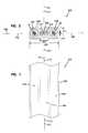
- FIG. 3is an end view of a test system for testing the flexibility of the strength members of the fiber optic cables of FIGS. 1 and 2 .
- FIG. 4is a top view of the test system of FIG. 9 .
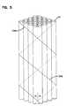
- FIG. 5is a perspective view of contrahelical separating members that can be used to group together the optical fibers of the fiber optic cable of FIGS. 1 and 1 and can also be used to separate the optical fibers from the cable jacket material enclosing the fibers.
- FIG. 6is a plan view of another fiber optic cable in accordance with the principles of the present disclosure.
- FIG. 7is a transverse cross-sectional view of the fiber optic cable of FIG. 6 taken along section line 7 - 7 .
- FIGS. 1 and 2depict another fiber optic cable 100 in accordance with the principles of the present disclosure.
- the cable 100includes an outer jacket 102 defining first, second and third generally parallel passages 104 , 105 and 106 .
- the cable 100also includes a plurality of optical fibers 12 positioned within the first and second passages 104 , 105 and a strength member 107 (i.e., a tensile reinforcing member) positioned within the third passage 106 .
- a strength member 107i.e., a tensile reinforcing member
- the optical fibers 12are manufactured to reduce the sensitivity of the optical fiber 12 to micro or macro-bending (hereinafter referred to as “bend-insensitive”).
- An exemplary bend insensitive optical fiberhas been described in U.S. Pat. Application Publication Nos. 2007/0127878 and 2007/0280615 that are hereby incorporated by reference in their entirety.
- An exemplary bend-insensitive optical fiberis commercially available from Draka Comteq under the name BendBright XS.
- the cable 100has an elongated transverse cross-sectional profile (e.g., a flattened cross-sectional profile, an oblong cross-sectional profile, an obround cross-sectional profile, etc.) defined by the outer jacket 102 .
- the cable 100defines a major axis 108 and a minor axis 110 .
- a width W 1 of the outer jacket 102extends along the major axis 108 and a thickness T 1 of the outer jacket 102 extends along the minor axis 110 .
- the width W 1is longer than the thickness T 1 .
- the width W 1is at least 100% longer than the thickness.
- the width W 1is a maximum width of the outer jacket 102 and the thickness T 1 is a maximum thickness of the outer jacket 102 .
- the transverse cross-sectional profile defined by the outer jacket 102is generally rectangular with rounded ends.
- the major axis 108 and the minor axis 110intersect perpendicularly at a lengthwise axis 112 of the cable 100 .
- the construction of the cable 100allows the cable 100 to be bent more easily along a plane P 1 that coincides with the minor axis 110 than along a plane P 2 that coincides with the major axis 108 .
- the cable 100is preferably bent along the plane P 1 .
- the outer jacket 102defines the elongate transverse cross-sectional profile of the cable 100 .
- the passages 104 - 106are aligned along the major axis 108 of the cable 100 with the passage 106 located between the passages 104 , 105 .
- the first and second passages 104 , 105have generally circular transverse cross-sectional profiles while the passage 106 has an elongate transverse cross-sectional profile.
- the passage 106is elongated in an orientation that extends along the major axis 108 of the cable 100 .
- the first and second passages 104 , 105are not lined with buffer tubes. However, in other embodiments, buffer tubes may be used.
- the outer jacket 102 of the cable 100can be shaped through an extrusion process and can be made by any number of different types of polymeric materials.
- the outer jacket 102can have a construction the resists post-extrusion shrinkage of the outer jacket 102 .
- the outer jacket 102can include a shrinkage reduction material disposed within a polymeric base material (e.g., polyethylene).
- a polymeric base materiale.g., polyethylene
- the shrinkage reduction materialis a liquid crystal polymer (LCP).
- LCPliquid crystal polymer
- the concentration of shrinkage materiale.g. LCP
- the shrinkage reduction materialconstitutes less than about 10% of the total weight of the outer jacket 102 .
- the shrinkage reduction materialconstitutes less than about 5% of the total weight of the outer jacket 102 . In another embodiment, the shrinkage reduction material constitutes less than about 2% of the total weight of the outer jacket 102 . In another embodiment, shrinkage reduction material constitutes less than about 1.9%, less than about 1.8%, less than 1.7%, less than about 1.6%, less than about 1.5%, less than about 1.4%, less than about 1.3%, less than about 1.2%, less than about 1.1%, or less than about 1.0% of the total weight of the outer jacket 102 .
- Example base materials for the outer jacket 102include low-smoke zero halogen materials such as low-smoke zero halogen polyolefin and polycarbon.
- the base materialcan include thermal plastic materials such as polyethylene, polypropylene, ethylene-propylene, copolymers, polystyrene and styrene copolymers, polyvinyl chloride, polyamide (nylon), polyesters such as polyethylene terephthalate, polyetheretherketone, polyphenylene sulfide, polyetherimide, polybutylene terephthalate, as well as other plastic materials.
- the outer jacket 102can be made of low density, medium density or high density polyethylene materials.
- Such polyethylene materialscan include low density, medium density or high density ultra-high molecular weight polyethylene materials.
- the first and second passages 104 , 105 of the outer jacket 102are each sized to receive one or more of the bend insensitive fibers 12 .
- the bend insensitive fibersare preferably unbuffered and in certain embodiments have outer diameters in the range of 230-270 ⁇ m.
- the first and second passages 104 , 105are each sized to receive at least 16 of the bend insensitive fibers 12 .
- passages 104 , 105it is preferred for the passages 104 , 105 to be dry and not to be filled with a water-blocking gel. Instead, to prevent water from migrating along the passages 104 , 105 , structures such water-swellable fibers, water-swellable tape, or water-swellable yarn can be provided within the passages 104 , 105 along with the fibers 12 . However, in certain embodiments water-blocking gel may be used.
- the strength member 107 of the cable 100preferably has a transverse cross-sectional profile that matches the transverse cross-sectional profile of the third passage 106 . As shown at FIG. 2 , the strength member 107 has a transverse cross-sectional width W 2 that is greater than a transverse cross-sectional thickness T 2 of the strength member 107 .
- the width W 2extends along the major axis 108 of the cable while the thickness T 2 extends along the minor axis 110 of the cable 100 . In the depicted embodiment, the thickness T 2 is bisected by the major axis 108 .
- the width W 2 of the strength member 107is at least 50% longer than the thickness T 2 , or the width W 2 of the strength member 107 is at least 75% longer than the thickness T 2 , or the width W 2 of the strength member 107 is at least 100% longer than the thickness T 2 , or the width W 2 of the strength member 107 is at least 200% longer than the thickness T 2 , or the width W 2 of the strength member 107 is at least 300% longer than the thickness T 2 , or the width W 2 of the strength member 107 is at least 400% longer than the thickness T 2 .
- the width W 2is a maximum width of the strength member 107 and the thickness T 2 is a maximum thickness of the strength member 107 .
- the strength member 107is bonded to the outer jacket 102 .
- the bonding between the strength member 107 and the outer jacket 102can be chemical bonding or thermal bonding.
- the strength member 107may be coated with or otherwise provided with a material having bonding characteristics (e.g., ethylene acetate) to bond the strength member 107 to the outer jacket 102 .
- the strength member 107preferably has a construction that is highly flexible and highly strong in tension.
- the strength member 107provides the vast majority of the tensile load capacity of the cable 100 .
- the strength member 107carries at least 95% of a 150 pound tensile load applied to the cable 100 in a direction along the lengthwise axis 112 .
- the strength member 107can carry a 150 pound tensile load applied in an orientation extending along a central longitudinal axis of the strength member 107 without undergoing meaningful deterioration of the tensile properties of the strength member 107 .
- the strength member 107can carry a 200 pound tensile load applied in an orientation extending along the central longitudinal axis of the strength member 107 without undergoing meaningful deterioration in its tensile properties. In still another embodiment, the strength member 107 can carry a 300 pound tensile load applied in an orientation that extends along the central longitudinal axis of the strength member 107 without experiencing meaningful deterioration of its tensile properties.
- the strength member 107it is preferred for the strength member 107 to be able to provide the tensile strengths described above while concurrently being highly flexible.
- tensile loadis applied to the cable 102 in a direction that extends along the lengthwise axis 112 of the cable 100 .
- tensile loadis applied to the strength member 107 in a direction that extends along central longitudinal axis 114 of the strength member 107 .
- a strength member 107 having tensile strength characteristics as described abovealso has a flexibility that allows the strength member 107 to be wrapped at least 360 degrees around a mandrel 300 (see FIGS. 3 and 4 ) having a 10 millimeter outer diameter for one hour without undergoing/experiencing meaningful deterioration/degradation of the tensile strength properties of the strength member 107 .
- the 360 degree wrapis aligned generally along a single plane P 3 (i.e., the 360 degree wrap does not form a helix having an extended axial length). In this way, the strength member 107 conforms to the outer diameter of the mandrel and generally forms a circle having an inner diameter of 10 millimeters.
- the strength member 107maintains at least 95% of its pre-mandrel wrap test tensile strength after having been subjected to the mandrel wrap test. In certain embodiments, the strength member 107 does not “broom stick” when subjected to the mandrel wrap test described. As used herein, the term “broom stick” means to have reinforcing elements of the strength member visually separate from the main body of the strength member 107 . In certain embodiments, the strength member 107 does not generate any audible cracking when exposed to the mandrel wrap test.
- the strength member 107is formed by a generally flat layer of reinforcing elements (e.g., fibers or yarns such as aramid fibers or yarns) embedded or otherwise integrated within a binder to form a flat reinforcing structure (e.g., a structure such as a sheet-like structure, a film-like structure, or a tape-like structure).
- the binderis a polymeric material such ethylene acetate acrylite (e.g., UV-cured, etc.), silicon (e.g., RTV, etc.), polyester films (e.g., biaxially oriented polyethylene terephthalate polyester film, etc.), and polyisobutylene.
- the bindermay be a matrix material, an adhesive material, a finish material, or another type of material that binds, couples or otherwise mechanically links together reinforcing elements.
- the strength member 107can have a glass reinforced polymer (GRP) construction.
- the glass reinforced polymercan include a polymer base material reinforced by a plurality of glass fibers such as E-glass, S-glass or other types of glass fiber.
- the polymer used in the glass reinforced polymeris preferably relatively soft and flexible after curing.
- the polymerhas a Shore A hardness less than 50 after curing.
- the polymerhas a Shore A hardness less than 46 after curing.
- the polymerhas a Shore A hardness in the range of about 34-46.
- the strength member 107can have a width of about 0.085 inches and a thickness of about 0.045 inches. In another embodiment, such a strength member may have a width of about 0.125 inches and a thickness of about 0.030 inches. In still further embodiments, the strength member has a thickness in the range of 0.020-0.040 inches, or in the range of 0.010-0.040 inches, or in the range of 0.025-0.035 inches. Of course, other dimensions could be used as well. In additional embodiments, the strength member may have a width in the range of 0.070-0.150 inches. Of course, other sizes could be used as well.
- the strength member 107preferably does not provide the cable 100 with meaningful resistance to compression loading in an orientation extending along the lengthwise axis 112 .
- the outer jacket 102provides greater resistance to compression than the strength member 107 in an orientation extending along the lengthwise axis 112 .
- the reinforcing member 107does not provide the cable 100 with meaningful compressive reinforcement in an orientation that extends along the lengthwise axis 112 .
- resistance to shrinkage or other compression of the cable 100 along the lengthwise axis 112can be provided by the outer jacket 102 itself through the provision of the shrinkage reduction material within the base material of the outer jacket 102 .
- a compressive loadis applied to the cable 100 along the lengthwise axis 112 , a vast majority of the compressive load will be carried by the outer jacket 102 as compared to the strength member 107 .
- first and second sets of separating members 120 a , 120 bcan be contra-helically served about the group of fibers 12 .
- first and second sets of separating members 120 a , 120 bcan be contra-helically served about the group of fibers 12 .
- the first set of separating members 120 ais disposed about the fibers 12 in a generally right-handed helical wrap configuration while the second set of separating members 120 b is disposed about the optical fibers 12 in a generally left-handed helical wrap configuration.
- the separating members 120 a , 120 bcan have helical wrap angles ⁇ less than 20 degrees or less than 15 degrees.
- the separating memberscan be yarns.
- the separating membersare formed by aramid yarn.
- water swellable materialcan be coated on or otherwise incorporated into the binding members.
- the contra-helical serve of separating membersextends around the entire group of optical fibers 12 .
- contra-helical servingcan be used to divide the fibers 12 into separate groups.
- the fibers 12can be separated into four groups of 4 optical fibers 12 with contra-helical serving provided around each of the groups of 4 fibers 12 .
- FIGS. 6 and 7depict another cable 200 in accordance with the principles of the present disclosure.
- the cable 200includes many of the same components as the as the cable 100 (e.g., the strength member 107 , the optical fibers 12 , the passages 104 - 106 ).
- the cable 200includes an outer jacket 202 having a transverse cross-sectional profile that has been modified to include a variable thickness (e.g., a dual thickness) to improve the crush-resistance of the cable 200 .
- Crush resistancecan be significant when the cable is used with a cable clamp such as a “P-clamp.”
- the outer jacket 202 of the cable 200has an elongated transverse cross-sectional profile.
- the cable 200defines a major axis 208 and a minor axis 210 .
- a width W 3 of the outer jacket 202extends along the major axis 208 and thicknesses T 3 , T 4 of the outer jacket 202 extend along the minor axis 210 .
- the thickness T 3is smaller than the thickness T 4
- the width W 3is greater than the thickness T 4 .
- the thickness T 3is defined by first and second portions 230 , 231 of the jacket 202 in which the first and second passages 104 , 105 containing the optical fibers 12 are formed.
- the thickness T 4is defined by a third portion 232 (i.e., a middle or intermediate portion) of the jacket 202 in which the third passage 106 containing the strength member 107 is formed.
- the first and second portions 230 , 231define end regions of the transverse cross-sectional profile of the cable 200 and the third portion 232 defines a mid region of the transverse cross-sectional profile of the cable 200 .
- the thickness T 3coincides with centers of the passages 104 , 105 and the thickness T 4 coincides with a center of the third passage 106 .
- the increased thickness T 4 provided by the third portion 232 of the jacket 202carries most of the compressive load thereby preventing the passages 104 , 105 from being deformed. In this way, the fibers 12 within the passage 104 , 105 are prevented from being damaged by the compressive action.
Landscapes
- Physics & Mathematics (AREA)
- General Physics & Mathematics (AREA)
- Optics & Photonics (AREA)
- Insulated Conductors (AREA)
Abstract
Description
Claims (17)
Priority Applications (1)
| Application Number | Priority Date | Filing Date | Title |
|---|---|---|---|
| US12/909,541US8184935B2 (en) | 2009-10-21 | 2010-10-21 | Flat drop cable with center strength member |
Applications Claiming Priority (3)
| Application Number | Priority Date | Filing Date | Title |
|---|---|---|---|
| US25375409P | 2009-10-21 | 2009-10-21 | |
| US25575609P | 2009-10-28 | 2009-10-28 | |
| US12/909,541US8184935B2 (en) | 2009-10-21 | 2010-10-21 | Flat drop cable with center strength member |
Publications (2)
| Publication Number | Publication Date |
|---|---|
| US20110091174A1 US20110091174A1 (en) | 2011-04-21 |
| US8184935B2true US8184935B2 (en) | 2012-05-22 |
Family
ID=43879364
Family Applications (1)
| Application Number | Title | Priority Date | Filing Date |
|---|---|---|---|
| US12/909,541Expired - Fee RelatedUS8184935B2 (en) | 2009-10-21 | 2010-10-21 | Flat drop cable with center strength member |
Country Status (2)
| Country | Link |
|---|---|
| US (1) | US8184935B2 (en) |
| WO (1) | WO2011050181A2 (en) |
Cited By (10)
| Publication number | Priority date | Publication date | Assignee | Title |
|---|---|---|---|---|
| US20110217010A1 (en)* | 2010-03-02 | 2011-09-08 | Adc Telecommunications, Inc. | Fiber optic cable assembly |
| US20130009018A1 (en)* | 2011-07-10 | 2013-01-10 | John Palahnuk | Method of cable fabrication |
| US20150129751A1 (en)* | 2013-11-12 | 2015-05-14 | Baker Hughes Incorporated | Distributed sensing system employing a film adhesive |
| US9472314B2 (en) | 2013-05-14 | 2016-10-18 | Commscope Technologies Llc | Power/fiber hybrid cable |
| US9557505B2 (en) | 2013-03-18 | 2017-01-31 | Commscope Technologies Llc | Power and optical fiber interface |
| WO2017166163A1 (en)* | 2016-03-31 | 2017-10-05 | Corning Optical Fiber Cable (Chengdu) Co., Ltd. | Optical fiber drop cable |
| US9893811B2 (en) | 2013-03-18 | 2018-02-13 | Commscope Technologies Llc | Architecture for a wireless network |
| US10151899B2 (en) | 2014-01-22 | 2018-12-11 | Commscope Technologies Llc | Flat drop cable with features for enhancing stripability |
| US10649165B2 (en) | 2017-04-13 | 2020-05-12 | Commscope Technologies Llc | Flat drop cable with features for enhanced gel retention and stripability |
| US11119546B2 (en) | 2016-11-09 | 2021-09-14 | Commscope, Inc. Of North Carolina | Exchangeable powered infrastructure module |
Families Citing this family (4)
| Publication number | Priority date | Publication date | Assignee | Title |
|---|---|---|---|---|
| EP4071532A1 (en)* | 2008-05-28 | 2022-10-12 | Commscope Technologies LLC | Fiber optic cable |
| US8107781B2 (en)* | 2009-11-20 | 2012-01-31 | Adc Telecommunications, Inc. | Fiber optic cable |
| AU2012285834B2 (en)* | 2011-07-21 | 2016-02-25 | Commscope Technologies Llc | Method for extruding a drop cable |
| FR2991964B1 (en)* | 2012-06-14 | 2014-12-12 | Decathlon Sa | FLEXIBLE ANTI-THEFT DEVICE |
Citations (86)
| Publication number | Priority date | Publication date | Assignee | Title |
|---|---|---|---|---|
| DE2513723A1 (en) | 1975-03-25 | 1976-10-07 | Siemens Ag | Flexible optical cable - has steel wire reinforcement in common sheath to accept strains |
| US3991014A (en) | 1974-05-10 | 1976-11-09 | E. I. Du Pont De Nemours And Company | Polyesters of derivatives of hydroquinone and bis(carboxyphenyl)ether |
| GB1483845A (en) | 1975-08-14 | 1977-08-24 | Standard Telephones Cables Ltd | Land lines |
| US4067852A (en) | 1976-05-13 | 1978-01-10 | Celanese Corporation | Melt processable thermotropic wholly aromatic polyester containing polybenzoyl units |
| US4083829A (en) | 1976-05-13 | 1978-04-11 | Celanese Corporation | Melt processable thermotropic wholly aromatic polyester |
| US4089585A (en) | 1974-12-18 | 1978-05-16 | Bicc Limited | Optical guides |
| US4130545A (en) | 1977-09-12 | 1978-12-19 | Celanese Corporation | Melt processable thermotropic wholly aromatic polyester comprising both para-oxybenzoyl and meta-oxybenzoyl moieties |
| US4161470A (en) | 1977-10-20 | 1979-07-17 | Celanese Corporation | Polyester of 6-hydroxy-2-naphthoic acid and para-hydroxy benzoic acid capable of readily undergoing melt processing |
| US4199225A (en) | 1978-04-07 | 1980-04-22 | Bicc Limited | Optical guides |
| US4304462A (en) | 1980-04-16 | 1981-12-08 | The United States Of America As Represented By The Secretary Of The Army | Thermal hardened fiber optic cables |
| US4318842A (en) | 1980-10-06 | 1982-03-09 | Celanese Corporation | Polyester of 6-hydroxy-2-naphthoic acid, aromatic diol, and 1,4-cyclohexanedicarboxylic acid capable of undergoing melt processing |
| GB2096343A (en) | 1981-04-01 | 1982-10-13 | Pirelli General Plc | Optical fibre cable |
| US4359598A (en) | 1977-05-13 | 1982-11-16 | Bicc Limited | Overhead electric transmission systems |
| US4401361A (en)* | 1972-06-06 | 1983-08-30 | Bicc Limited | Optical guides |
| US4420220A (en) | 1979-06-25 | 1983-12-13 | Bicc Public Limited Company | Optical guides |
| US4468364A (en) | 1983-04-28 | 1984-08-28 | Celanese Corporation | Process for extruding thermotropic liquid crystalline polymers |
| US4515435A (en) | 1982-08-10 | 1985-05-07 | Cooper Industries, Inc. | Thermally stabilized fiber optic cable |
| US4553815A (en) | 1983-02-04 | 1985-11-19 | Westinghouse Electric Corp. | Optical fiber cable construction |
| US4569420A (en) | 1982-12-13 | 1986-02-11 | Pickett Wiley J | Lubricating method and system for use in cable pulling |
| US4659174A (en) | 1983-05-19 | 1987-04-21 | U.S. Philips Corporation | Optical cable element and cable, respectively, and method of manufacturing same |
| US4715677A (en)* | 1985-12-24 | 1987-12-29 | Sumitomo Electric Research Triangle, Inc. | Ruggedized optical fiber cable |
| US4729628A (en) | 1986-11-14 | 1988-03-08 | Siecor Corporation | Fiber optic dropwire |
| US4761053A (en) | 1985-08-28 | 1988-08-02 | American Telephone And Telegraph Company, At&T Bell Laboratories | Communications transmission media |
| US4807962A (en) | 1986-03-06 | 1989-02-28 | American Telephone And Telegraph Company, At&T Bell Laboratories | Optical fiber cable having fluted strength member core |
| US4818060A (en) | 1987-03-31 | 1989-04-04 | American Telephone And Telegraph Company, At&T Bell Laboratories | Optical fiber building cables |
| US4844575A (en) | 1987-04-10 | 1989-07-04 | American Telephone And Telegraph Company, At&T Bell Laboratories | Optical fiber cable |
| US4852965A (en) | 1987-02-27 | 1989-08-01 | American Telephone And Telegraph Company At&T Bell Laboratories | Composite service and distribution communications media |
| US4895427A (en) | 1984-11-13 | 1990-01-23 | Siecor Corporation | Fiber optic cable |
| US4909592A (en) | 1988-09-29 | 1990-03-20 | American Telephone And Telegraph Company, At&T Bell Laboratories | Communication cable having water blocking provisions in core |
| US5015063A (en) | 1989-10-25 | 1991-05-14 | At&T Bell Laboratories | Optical fiber cable core |
| US5125063A (en) | 1990-11-08 | 1992-06-23 | At&T Bell Laboratories | Lightweight optical fiber cable |
| US5157752A (en) | 1991-10-24 | 1992-10-20 | Northern Telecom Limited | Optical fiber cable with intermingled water blocking means and method of making same |
| US5214730A (en) | 1991-05-13 | 1993-05-25 | Nippon Telegraph And Telephone Corporation | Multifiber optical connector plug with low reflection and low insertion loss |
| US5229851A (en) | 1992-04-02 | 1993-07-20 | Pirelli Cable Corporation | Optical fiber cable with large number of ribbon units containing optical fibers and enclosed in tubes |
| US5345526A (en) | 1993-02-11 | 1994-09-06 | Comm/Scope | Fiber optic cable having buffer tubes with optical fiber bundles therein and method for making same |
| US5345525A (en) | 1992-01-28 | 1994-09-06 | At&T Bell Laboratories | Utility optical fiber cable |
| US5448670A (en) | 1994-06-10 | 1995-09-05 | Commscope, Inc. | Elliptical aerial self-supporting fiber optic cable and associated apparatus and methods |
| WO1996015466A1 (en) | 1994-11-11 | 1996-05-23 | Metal Manufactures Limited | Optical fibre cable |
| GB2296575A (en) | 1994-12-22 | 1996-07-03 | France Telecom | Fibre optic cable ,manufacturing process and plant |
| US5557698A (en) | 1994-08-19 | 1996-09-17 | Belden Wire & Cable Company | Coaxial fiber optical cable |
| US5627932A (en) | 1995-08-23 | 1997-05-06 | Siecor Corporation | Reduced diameter indoor fiber optic cable |
| US5668912A (en) | 1996-02-07 | 1997-09-16 | Alcatel Na Cable Systems, Inc. | Rectangular optical fiber cable |
| US5737470A (en) | 1996-03-12 | 1998-04-07 | Nippon Telegraph And Telephone Corporation | Flat optical fiber cable |
| US5802231A (en)* | 1996-03-12 | 1998-09-01 | Nippon Telegraph And Telephone Corporation | Flat optical fiber cable |
| US5838864A (en) | 1997-04-30 | 1998-11-17 | Lucent Technologies Inc. | Optical cable having an improved strength system |
| US5970196A (en) | 1997-09-22 | 1999-10-19 | Siecor Corporation | Fiber optic protective member with removable section to facilitate separation thereof |
| US5978536A (en) | 1996-09-16 | 1999-11-02 | Pirelli Cavi E Sistemi S.P.A. | Optical cable with core decoupled from sheath and yarn strands uniformly adhering to sheath |
| US5982966A (en) | 1996-12-19 | 1999-11-09 | Alcatel | Asymmetric structure fiber optic cable |
| US6014487A (en) | 1997-06-30 | 2000-01-11 | Siecor Corporation | Fiber optic cable |
| US6088499A (en) | 1997-09-30 | 2000-07-11 | Siecor Corporation | Fiber optic cable with ripcord |
| US6137936A (en) | 1999-07-22 | 2000-10-24 | Pirelli Cables And Systems Llc | Optical fiber cable with single strength member in cable outer jacket |
| US6249628B1 (en) | 1999-06-10 | 2001-06-19 | Siecor Operations, Llc | Fiber optic cable units |
| US6256438B1 (en) | 1999-10-29 | 2001-07-03 | Siecor Operations, Llc | Fiber optic drop cable |
| US6321012B1 (en) | 1999-08-30 | 2001-11-20 | Alcatel | Optical fiber having water swellable material for identifying grouping of fiber groups |
| US6347172B1 (en) | 2000-06-28 | 2002-02-12 | Alcatel | Cable having side-emitting fiber under transparent or translucent cable jacket |
| US6356690B1 (en) | 1999-10-20 | 2002-03-12 | Corning Cable Systems Llc | Self-supporting fiber optic cable |
| US6370303B1 (en) | 2000-10-20 | 2002-04-09 | Pirelli Cables And Systems Llc | Optical fiber cable with support member for indoor and outdoor use |
| US6434307B1 (en)* | 2000-08-15 | 2002-08-13 | Alcoa Fujikura Ltd. | Low profile optical fiber ribbon cable |
| US6493491B1 (en) | 1999-09-28 | 2002-12-10 | Alcatel | Optical drop cable for aerial installation |
| US6501888B2 (en) | 1999-09-16 | 2002-12-31 | Corning Cable Systems Llc | Fiber optic cables with strength members and an apparatus for making the same |
| US6542674B1 (en) | 2000-08-25 | 2003-04-01 | Corning Cable Systems Llc | Fiber optic cables with strength members |
| US6546175B1 (en) | 2000-05-26 | 2003-04-08 | Corning Cable Systems Llc | Self-supporting fiber optic cable |
| US6621964B2 (en)* | 2001-05-21 | 2003-09-16 | Corning Cable Systems Llc | Non-stranded high strength fiber optic cable |
| US6701047B1 (en) | 1999-03-31 | 2004-03-02 | Corning Cable Systems Llc | Fiber optic buffer unit and cables including the same |
| US6744954B1 (en) | 1998-11-20 | 2004-06-01 | Sumitomo Electric Industries, Ltd. | Submarine optical cable, optical fiber unit employed in the submarine optical cable, and method of making optical fiber unit |
| US6807347B2 (en) | 2001-06-25 | 2004-10-19 | Corning Cable Systems Llc | High density fiber optic cable |
| US6813422B1 (en) | 2003-06-23 | 2004-11-02 | Alcoa Fujikura Limited | Flexible fiber optic cable |
| US6836603B1 (en) | 2003-08-14 | 2004-12-28 | Furukawa Electric North America, Inc. | Optical fiber cables |
| US6901191B2 (en) | 2001-11-12 | 2005-05-31 | Corning Cable Systems Llc | High density fiber optic cable |
| US6928217B2 (en) | 2003-07-18 | 2005-08-09 | Corning Cable Systems Llc | Fiber optic cable having a strength member |
| US20060140557A1 (en) | 2001-03-30 | 2006-06-29 | Parris Donald R | Fiber optic cable with strength member formed from a sheet |
| US20060159407A1 (en) | 2005-01-18 | 2006-07-20 | Adc Telecommunications, Inc. | Low shrink telecommunications cable and methods for manufacturing the same |
| US20060291787A1 (en) | 2005-06-27 | 2006-12-28 | Seddon David A | Fiber optic cable having strength component |
| WO2007016479A2 (en) | 2005-07-29 | 2007-02-08 | Corning Cable Systems Llc | Fiber optic cables and assemblies for fiber to the subscriber applications |
| US7197215B2 (en) | 2004-12-15 | 2007-03-27 | Corning Cable Systems, Llc. | Fiber optic cables with easy access features |
| US7218821B2 (en) | 2004-08-20 | 2007-05-15 | Furukawa Electric North America Inc. | Optical fiber cables |
| US20070127878A1 (en) | 2005-11-10 | 2007-06-07 | Draka Comteq B.V. | Single mode optical fiber |
| DE202007006658U1 (en) | 2007-05-10 | 2007-07-19 | Nexans | Cable with fiber optic cables |
| US20070280615A1 (en) | 2006-04-10 | 2007-12-06 | Draka Comteq B.V. | Single-mode Optical Fiber |
| US7349642B2 (en) | 2004-03-10 | 2008-03-25 | Matsushita Electric Industrial Co., Ltd. | Image heating apparatus including PID control |
| US20080187276A1 (en) | 2007-02-02 | 2008-08-07 | Reginald Roberts | Flexible optical fiber tape and distribution cable assembly using same |
| US7458103B2 (en) | 2003-05-08 | 2008-12-02 | Teijin Aramid Gmbh | Flexible penetration-resistant package and use thereof |
| US20090297104A1 (en) | 2008-05-28 | 2009-12-03 | Kachmar Wayne M | Fiber optic cable |
| US20090317047A1 (en) | 2008-06-19 | 2009-12-24 | Adc Telecommunications, Inc. | Methods and systems for distributing fiber optic telecommunications services to local area |
| US20090317039A1 (en) | 2008-06-19 | 2009-12-24 | Blazer Bradley J | Fiber optic cable having armor with easy access features |
| US7693375B2 (en) | 2002-12-19 | 2010-04-06 | Corning Cable Systems Llc | Fiber optic cable having a dry insert |
- 2010
- 2010-10-21USUS12/909,541patent/US8184935B2/ennot_activeExpired - Fee Related
- 2010-10-21WOPCT/US2010/053580patent/WO2011050181A2/enactiveApplication Filing
Patent Citations (92)
| Publication number | Priority date | Publication date | Assignee | Title |
|---|---|---|---|---|
| US4401361A (en)* | 1972-06-06 | 1983-08-30 | Bicc Limited | Optical guides |
| US3991014A (en) | 1974-05-10 | 1976-11-09 | E. I. Du Pont De Nemours And Company | Polyesters of derivatives of hydroquinone and bis(carboxyphenyl)ether |
| US4089585A (en) | 1974-12-18 | 1978-05-16 | Bicc Limited | Optical guides |
| DE2513723A1 (en) | 1975-03-25 | 1976-10-07 | Siemens Ag | Flexible optical cable - has steel wire reinforcement in common sheath to accept strains |
| GB1483845A (en) | 1975-08-14 | 1977-08-24 | Standard Telephones Cables Ltd | Land lines |
| US4067852A (en) | 1976-05-13 | 1978-01-10 | Celanese Corporation | Melt processable thermotropic wholly aromatic polyester containing polybenzoyl units |
| US4083829A (en) | 1976-05-13 | 1978-04-11 | Celanese Corporation | Melt processable thermotropic wholly aromatic polyester |
| US4359598A (en) | 1977-05-13 | 1982-11-16 | Bicc Limited | Overhead electric transmission systems |
| US4130545A (en) | 1977-09-12 | 1978-12-19 | Celanese Corporation | Melt processable thermotropic wholly aromatic polyester comprising both para-oxybenzoyl and meta-oxybenzoyl moieties |
| US4161470A (en) | 1977-10-20 | 1979-07-17 | Celanese Corporation | Polyester of 6-hydroxy-2-naphthoic acid and para-hydroxy benzoic acid capable of readily undergoing melt processing |
| US4199225A (en) | 1978-04-07 | 1980-04-22 | Bicc Limited | Optical guides |
| US4420220A (en) | 1979-06-25 | 1983-12-13 | Bicc Public Limited Company | Optical guides |
| US4304462A (en) | 1980-04-16 | 1981-12-08 | The United States Of America As Represented By The Secretary Of The Army | Thermal hardened fiber optic cables |
| US4318842A (en) | 1980-10-06 | 1982-03-09 | Celanese Corporation | Polyester of 6-hydroxy-2-naphthoic acid, aromatic diol, and 1,4-cyclohexanedicarboxylic acid capable of undergoing melt processing |
| GB2096343A (en) | 1981-04-01 | 1982-10-13 | Pirelli General Plc | Optical fibre cable |
| US4515435A (en) | 1982-08-10 | 1985-05-07 | Cooper Industries, Inc. | Thermally stabilized fiber optic cable |
| US4569420A (en) | 1982-12-13 | 1986-02-11 | Pickett Wiley J | Lubricating method and system for use in cable pulling |
| US4553815A (en) | 1983-02-04 | 1985-11-19 | Westinghouse Electric Corp. | Optical fiber cable construction |
| US4468364A (en) | 1983-04-28 | 1984-08-28 | Celanese Corporation | Process for extruding thermotropic liquid crystalline polymers |
| US4659174A (en) | 1983-05-19 | 1987-04-21 | U.S. Philips Corporation | Optical cable element and cable, respectively, and method of manufacturing same |
| US4895427A (en) | 1984-11-13 | 1990-01-23 | Siecor Corporation | Fiber optic cable |
| US4761053A (en) | 1985-08-28 | 1988-08-02 | American Telephone And Telegraph Company, At&T Bell Laboratories | Communications transmission media |
| US4715677A (en)* | 1985-12-24 | 1987-12-29 | Sumitomo Electric Research Triangle, Inc. | Ruggedized optical fiber cable |
| US4807962A (en) | 1986-03-06 | 1989-02-28 | American Telephone And Telegraph Company, At&T Bell Laboratories | Optical fiber cable having fluted strength member core |
| US4729628A (en) | 1986-11-14 | 1988-03-08 | Siecor Corporation | Fiber optic dropwire |
| US4852965A (en) | 1987-02-27 | 1989-08-01 | American Telephone And Telegraph Company At&T Bell Laboratories | Composite service and distribution communications media |
| US4818060A (en) | 1987-03-31 | 1989-04-04 | American Telephone And Telegraph Company, At&T Bell Laboratories | Optical fiber building cables |
| US4844575A (en) | 1987-04-10 | 1989-07-04 | American Telephone And Telegraph Company, At&T Bell Laboratories | Optical fiber cable |
| US4909592A (en) | 1988-09-29 | 1990-03-20 | American Telephone And Telegraph Company, At&T Bell Laboratories | Communication cable having water blocking provisions in core |
| US5015063A (en) | 1989-10-25 | 1991-05-14 | At&T Bell Laboratories | Optical fiber cable core |
| US5125063A (en) | 1990-11-08 | 1992-06-23 | At&T Bell Laboratories | Lightweight optical fiber cable |
| US5214730A (en) | 1991-05-13 | 1993-05-25 | Nippon Telegraph And Telephone Corporation | Multifiber optical connector plug with low reflection and low insertion loss |
| US5157752A (en) | 1991-10-24 | 1992-10-20 | Northern Telecom Limited | Optical fiber cable with intermingled water blocking means and method of making same |
| US5345525A (en) | 1992-01-28 | 1994-09-06 | At&T Bell Laboratories | Utility optical fiber cable |
| US5229851A (en) | 1992-04-02 | 1993-07-20 | Pirelli Cable Corporation | Optical fiber cable with large number of ribbon units containing optical fibers and enclosed in tubes |
| US5345526A (en) | 1993-02-11 | 1994-09-06 | Comm/Scope | Fiber optic cable having buffer tubes with optical fiber bundles therein and method for making same |
| US5448670A (en) | 1994-06-10 | 1995-09-05 | Commscope, Inc. | Elliptical aerial self-supporting fiber optic cable and associated apparatus and methods |
| US5557698A (en) | 1994-08-19 | 1996-09-17 | Belden Wire & Cable Company | Coaxial fiber optical cable |
| WO1996015466A1 (en) | 1994-11-11 | 1996-05-23 | Metal Manufactures Limited | Optical fibre cable |
| GB2296575A (en) | 1994-12-22 | 1996-07-03 | France Telecom | Fibre optic cable ,manufacturing process and plant |
| US5627932A (en) | 1995-08-23 | 1997-05-06 | Siecor Corporation | Reduced diameter indoor fiber optic cable |
| US5668912A (en) | 1996-02-07 | 1997-09-16 | Alcatel Na Cable Systems, Inc. | Rectangular optical fiber cable |
| US5737470A (en) | 1996-03-12 | 1998-04-07 | Nippon Telegraph And Telephone Corporation | Flat optical fiber cable |
| US5802231A (en)* | 1996-03-12 | 1998-09-01 | Nippon Telegraph And Telephone Corporation | Flat optical fiber cable |
| US5978536A (en) | 1996-09-16 | 1999-11-02 | Pirelli Cavi E Sistemi S.P.A. | Optical cable with core decoupled from sheath and yarn strands uniformly adhering to sheath |
| US5982966A (en) | 1996-12-19 | 1999-11-09 | Alcatel | Asymmetric structure fiber optic cable |
| US5838864A (en) | 1997-04-30 | 1998-11-17 | Lucent Technologies Inc. | Optical cable having an improved strength system |
| US6014487A (en) | 1997-06-30 | 2000-01-11 | Siecor Corporation | Fiber optic cable |
| US5970196A (en) | 1997-09-22 | 1999-10-19 | Siecor Corporation | Fiber optic protective member with removable section to facilitate separation thereof |
| US6088499A (en) | 1997-09-30 | 2000-07-11 | Siecor Corporation | Fiber optic cable with ripcord |
| US6744954B1 (en) | 1998-11-20 | 2004-06-01 | Sumitomo Electric Industries, Ltd. | Submarine optical cable, optical fiber unit employed in the submarine optical cable, and method of making optical fiber unit |
| US6701047B1 (en) | 1999-03-31 | 2004-03-02 | Corning Cable Systems Llc | Fiber optic buffer unit and cables including the same |
| US6249628B1 (en) | 1999-06-10 | 2001-06-19 | Siecor Operations, Llc | Fiber optic cable units |
| US6137936A (en) | 1999-07-22 | 2000-10-24 | Pirelli Cables And Systems Llc | Optical fiber cable with single strength member in cable outer jacket |
| US6321012B1 (en) | 1999-08-30 | 2001-11-20 | Alcatel | Optical fiber having water swellable material for identifying grouping of fiber groups |
| US6501888B2 (en) | 1999-09-16 | 2002-12-31 | Corning Cable Systems Llc | Fiber optic cables with strength members and an apparatus for making the same |
| US6493491B1 (en) | 1999-09-28 | 2002-12-10 | Alcatel | Optical drop cable for aerial installation |
| US6356690B1 (en) | 1999-10-20 | 2002-03-12 | Corning Cable Systems Llc | Self-supporting fiber optic cable |
| US6256438B1 (en) | 1999-10-29 | 2001-07-03 | Siecor Operations, Llc | Fiber optic drop cable |
| US6546175B1 (en) | 2000-05-26 | 2003-04-08 | Corning Cable Systems Llc | Self-supporting fiber optic cable |
| US6347172B1 (en) | 2000-06-28 | 2002-02-12 | Alcatel | Cable having side-emitting fiber under transparent or translucent cable jacket |
| US6434307B1 (en)* | 2000-08-15 | 2002-08-13 | Alcoa Fujikura Ltd. | Low profile optical fiber ribbon cable |
| US6542674B1 (en) | 2000-08-25 | 2003-04-01 | Corning Cable Systems Llc | Fiber optic cables with strength members |
| US6714710B2 (en) | 2000-08-25 | 2004-03-30 | Corning Cable Systems, Llc | Fiber optic cables with strength members |
| US6370303B1 (en) | 2000-10-20 | 2002-04-09 | Pirelli Cables And Systems Llc | Optical fiber cable with support member for indoor and outdoor use |
| US20060140557A1 (en) | 2001-03-30 | 2006-06-29 | Parris Donald R | Fiber optic cable with strength member formed from a sheet |
| US6621964B2 (en)* | 2001-05-21 | 2003-09-16 | Corning Cable Systems Llc | Non-stranded high strength fiber optic cable |
| US6807347B2 (en) | 2001-06-25 | 2004-10-19 | Corning Cable Systems Llc | High density fiber optic cable |
| US6937801B2 (en) | 2001-06-25 | 2005-08-30 | Corning Cable Systems Llc | High density fiber optic cable |
| US6901191B2 (en) | 2001-11-12 | 2005-05-31 | Corning Cable Systems Llc | High density fiber optic cable |
| US7113680B2 (en) | 2001-11-12 | 2006-09-26 | Corning Cable Systems, Llc | High density fiber optic cable |
| US7693375B2 (en) | 2002-12-19 | 2010-04-06 | Corning Cable Systems Llc | Fiber optic cable having a dry insert |
| US7458103B2 (en) | 2003-05-08 | 2008-12-02 | Teijin Aramid Gmbh | Flexible penetration-resistant package and use thereof |
| US6813422B1 (en) | 2003-06-23 | 2004-11-02 | Alcoa Fujikura Limited | Flexible fiber optic cable |
| US6928217B2 (en) | 2003-07-18 | 2005-08-09 | Corning Cable Systems Llc | Fiber optic cable having a strength member |
| US6836603B1 (en) | 2003-08-14 | 2004-12-28 | Furukawa Electric North America, Inc. | Optical fiber cables |
| US7349642B2 (en) | 2004-03-10 | 2008-03-25 | Matsushita Electric Industrial Co., Ltd. | Image heating apparatus including PID control |
| US7218821B2 (en) | 2004-08-20 | 2007-05-15 | Furukawa Electric North America Inc. | Optical fiber cables |
| US7197215B2 (en) | 2004-12-15 | 2007-03-27 | Corning Cable Systems, Llc. | Fiber optic cables with easy access features |
| US20100046894A1 (en) | 2005-01-18 | 2010-02-25 | Adc Telecommunications, Inc. | Low shrink telecommunications cable and methods for manufacturing the same |
| US7379642B2 (en) | 2005-01-18 | 2008-05-27 | Adc Telecommunications, Inc. | Low shrink telecommunications cable and methods for manufacturing the same |
| US7566474B2 (en) | 2005-01-18 | 2009-07-28 | Adc Telecommunications, Inc. | Low shrink telecommunications cable and methods for manufacturing the same |
| US20060159407A1 (en) | 2005-01-18 | 2006-07-20 | Adc Telecommunications, Inc. | Low shrink telecommunications cable and methods for manufacturing the same |
| US20060291787A1 (en) | 2005-06-27 | 2006-12-28 | Seddon David A | Fiber optic cable having strength component |
| WO2007016479A2 (en) | 2005-07-29 | 2007-02-08 | Corning Cable Systems Llc | Fiber optic cables and assemblies for fiber to the subscriber applications |
| US20070127878A1 (en) | 2005-11-10 | 2007-06-07 | Draka Comteq B.V. | Single mode optical fiber |
| US20070280615A1 (en) | 2006-04-10 | 2007-12-06 | Draka Comteq B.V. | Single-mode Optical Fiber |
| US20080187276A1 (en) | 2007-02-02 | 2008-08-07 | Reginald Roberts | Flexible optical fiber tape and distribution cable assembly using same |
| DE202007006658U1 (en) | 2007-05-10 | 2007-07-19 | Nexans | Cable with fiber optic cables |
| US20090297104A1 (en) | 2008-05-28 | 2009-12-03 | Kachmar Wayne M | Fiber optic cable |
| US20090317039A1 (en) | 2008-06-19 | 2009-12-24 | Blazer Bradley J | Fiber optic cable having armor with easy access features |
| US20090317047A1 (en) | 2008-06-19 | 2009-12-24 | Adc Telecommunications, Inc. | Methods and systems for distributing fiber optic telecommunications services to local area |
Non-Patent Citations (6)
| Title |
|---|
| ADC Spec Sheet, Fiber Optic Cable, Ruggedized Simplex and Duplex Cables, ADC®, Oct. 2005, 4 pages. |
| ADC Spec Sheet, Fiber Optic Cable, Tactical Cables, ADC®, Oct. 2005, 4 pages. |
| Fiber Optic Cable LCF(TM) Microcable: Plenum, ADC Telecommunications, Inc., 4 pages (Copyright 2005). |
| Fiber Optic Cable LCF™ Microcable: Plenum, ADC Telecommunications, Inc., 4 pages (Copyright 2005). |
| International Search Report and Written Opinion mailed Jun. 30, 2011. |
| Superior Essex, FTTP Tight Buffered Indoor/Outdoor Drop, Series W7, RoHS, Product Bulletin, OSP Fiber Produtcs, Nov. 2008, 2 pages. |
Cited By (23)
| Publication number | Priority date | Publication date | Assignee | Title |
|---|---|---|---|---|
| USRE50314E1 (en) | 2010-03-02 | 2025-02-25 | Commscope Technologies Llc | Fiber optic cable assembly and method |
| US8363994B2 (en) | 2010-03-02 | 2013-01-29 | Adc Telecommunications, Inc. | Fiber optic cable assembly |
| US20110217010A1 (en)* | 2010-03-02 | 2011-09-08 | Adc Telecommunications, Inc. | Fiber optic cable assembly |
| US20130009018A1 (en)* | 2011-07-10 | 2013-01-10 | John Palahnuk | Method of cable fabrication |
| US11215776B2 (en) | 2013-03-18 | 2022-01-04 | Commscope Technologies Llc | Power and optical fiber interface |
| US11656418B2 (en) | 2013-03-18 | 2023-05-23 | Commscope Technologies Llc | Power and optical fiber interface |
| US9557505B2 (en) | 2013-03-18 | 2017-01-31 | Commscope Technologies Llc | Power and optical fiber interface |
| US12405435B2 (en) | 2013-03-18 | 2025-09-02 | Commscope Technologies Llc | Power and optical fiber interface |
| US10502912B2 (en) | 2013-03-18 | 2019-12-10 | Commscope Technologies Llc | Power and optical fiber interface |
| US9893811B2 (en) | 2013-03-18 | 2018-02-13 | Commscope Technologies Llc | Architecture for a wireless network |
| US9977208B2 (en) | 2013-03-18 | 2018-05-22 | Commscope Technologies Llc | Power and optical fiber interface |
| US9472314B2 (en) | 2013-05-14 | 2016-10-18 | Commscope Technologies Llc | Power/fiber hybrid cable |
| US10163548B2 (en) | 2013-05-14 | 2018-12-25 | Commscope Technologies Llc | Power/fiber hybrid cable |
| US9837186B2 (en) | 2013-05-14 | 2017-12-05 | Commscope Technologies Llc | Power/fiber hybrid cable |
| US10892068B2 (en) | 2013-05-14 | 2021-01-12 | Commscope Technologies Llc | Power/fiber hybrid cable |
| US20150129751A1 (en)* | 2013-11-12 | 2015-05-14 | Baker Hughes Incorporated | Distributed sensing system employing a film adhesive |
| US10668706B2 (en) | 2013-11-12 | 2020-06-02 | Baker Hughes, A Ge Company, Llc | Distributed sensing system employing a film adhesive |
| US10151899B2 (en) | 2014-01-22 | 2018-12-11 | Commscope Technologies Llc | Flat drop cable with features for enhancing stripability |
| US10545308B2 (en) | 2014-01-22 | 2020-01-28 | Commscope Technologies Llc | Flat drop cable with features for enhancing stripability |
| CN109073845A (en)* | 2016-03-31 | 2018-12-21 | 成都康宁光缆有限公司 | Optical fibre drop cables |
| WO2017166163A1 (en)* | 2016-03-31 | 2017-10-05 | Corning Optical Fiber Cable (Chengdu) Co., Ltd. | Optical fiber drop cable |
| US11119546B2 (en) | 2016-11-09 | 2021-09-14 | Commscope, Inc. Of North Carolina | Exchangeable powered infrastructure module |
| US10649165B2 (en) | 2017-04-13 | 2020-05-12 | Commscope Technologies Llc | Flat drop cable with features for enhanced gel retention and stripability |
Also Published As
| Publication number | Publication date |
|---|---|
| WO2011050181A2 (en) | 2011-04-28 |
| WO2011050181A3 (en) | 2011-09-09 |
| US20110091174A1 (en) | 2011-04-21 |
Similar Documents
| Publication | Publication Date | Title |
|---|---|---|
| US8897613B2 (en) | Flat drop cable | |
| US8184935B2 (en) | Flat drop cable with center strength member | |
| US8238706B2 (en) | Flat drop cable with medial bump | |
| USRE50314E1 (en) | Fiber optic cable assembly and method | |
| AU2018236787B2 (en) | Armored optical fiber cable | |
| US7382955B1 (en) | Optical fiber cable with system and method for mid-span access | |
| US10473872B2 (en) | Fiber optic cable with large-diameter optical fibers | |
| CN100449344C (en) | Improved fiber optic cable | |
| CN105637397A (en) | Optical communication cable | |
| CN108738359B (en) | Fiber Optic Cables and Assemblies | |
| US20130022325A1 (en) | Drop Cable with Fiber Ribbon Conforming to Fiber Passage | |
| US10036863B2 (en) | Optical fiber cables with flat ribbon fibers | |
| AU2012285834B2 (en) | Method for extruding a drop cable | |
| US8781281B2 (en) | Drop cable with angled reinforcing member configurations | |
| US8544171B2 (en) | Method of terminating a fiber optic cable | |
| US8870473B2 (en) | Method of terminating a fiber optic cable | |
| NZ620028B2 (en) | Method for extruding a drop cable |
Legal Events
| Date | Code | Title | Description |
|---|---|---|---|
| AS | Assignment | Owner name:ADC TELECOMMUNICATIONS, INC., MINNESOTA Free format text:ASSIGNMENT OF ASSIGNORS INTEREST;ASSIGNOR:KACHMAR, WAYNE M.;REEL/FRAME:025583/0017 Effective date:20101116 | |
| STCF | Information on status: patent grant | Free format text:PATENTED CASE | |
| AS | Assignment | Owner name:TYCO ELECTRONICS SERVICES GMBH, SWITZERLAND Free format text:ASSIGNMENT OF ASSIGNORS INTEREST;ASSIGNOR:ADC TELECOMMUNICATIONS, INC.;REEL/FRAME:036060/0174 Effective date:20110930 | |
| AS | Assignment | Owner name:COMMSCOPE EMEA LIMITED, IRELAND Free format text:ASSIGNMENT OF ASSIGNORS INTEREST;ASSIGNOR:TYCO ELECTRONICS SERVICES GMBH;REEL/FRAME:036956/0001 Effective date:20150828 | |
| AS | Assignment | Owner name:COMMSCOPE TECHNOLOGIES LLC, NORTH CAROLINA Free format text:ASSIGNMENT OF ASSIGNORS INTEREST;ASSIGNOR:COMMSCOPE EMEA LIMITED;REEL/FRAME:037012/0001 Effective date:20150828 | |
| FPAY | Fee payment | Year of fee payment:4 | |
| AS | Assignment | Owner name:JPMORGAN CHASE BANK, N.A., AS COLLATERAL AGENT, ILLINOIS Free format text:PATENT SECURITY AGREEMENT (TERM);ASSIGNOR:COMMSCOPE TECHNOLOGIES LLC;REEL/FRAME:037513/0709 Effective date:20151220 Owner name:JPMORGAN CHASE BANK, N.A., AS COLLATERAL AGENT, ILLINOIS Free format text:PATENT SECURITY AGREEMENT (ABL);ASSIGNOR:COMMSCOPE TECHNOLOGIES LLC;REEL/FRAME:037514/0196 Effective date:20151220 Owner name:JPMORGAN CHASE BANK, N.A., AS COLLATERAL AGENT, IL Free format text:PATENT SECURITY AGREEMENT (ABL);ASSIGNOR:COMMSCOPE TECHNOLOGIES LLC;REEL/FRAME:037514/0196 Effective date:20151220 Owner name:JPMORGAN CHASE BANK, N.A., AS COLLATERAL AGENT, IL Free format text:PATENT SECURITY AGREEMENT (TERM);ASSIGNOR:COMMSCOPE TECHNOLOGIES LLC;REEL/FRAME:037513/0709 Effective date:20151220 | |
| AS | Assignment | Owner name:ALLEN TELECOM LLC, ILLINOIS Free format text:RELEASE BY SECURED PARTY;ASSIGNOR:JPMORGAN CHASE BANK, N.A.;REEL/FRAME:048840/0001 Effective date:20190404 Owner name:COMMSCOPE TECHNOLOGIES LLC, NORTH CAROLINA Free format text:RELEASE BY SECURED PARTY;ASSIGNOR:JPMORGAN CHASE BANK, N.A.;REEL/FRAME:048840/0001 Effective date:20190404 Owner name:REDWOOD SYSTEMS, INC., NORTH CAROLINA Free format text:RELEASE BY SECURED PARTY;ASSIGNOR:JPMORGAN CHASE BANK, N.A.;REEL/FRAME:048840/0001 Effective date:20190404 Owner name:ANDREW LLC, NORTH CAROLINA Free format text:RELEASE BY SECURED PARTY;ASSIGNOR:JPMORGAN CHASE BANK, N.A.;REEL/FRAME:048840/0001 Effective date:20190404 Owner name:COMMSCOPE, INC. OF NORTH CAROLINA, NORTH CAROLINA Free format text:RELEASE BY SECURED PARTY;ASSIGNOR:JPMORGAN CHASE BANK, N.A.;REEL/FRAME:048840/0001 Effective date:20190404 Owner name:COMMSCOPE, INC. OF NORTH CAROLINA, NORTH CAROLINA Free format text:RELEASE BY SECURED PARTY;ASSIGNOR:JPMORGAN CHASE BANK, N.A.;REEL/FRAME:049260/0001 Effective date:20190404 Owner name:ANDREW LLC, NORTH CAROLINA Free format text:RELEASE BY SECURED PARTY;ASSIGNOR:JPMORGAN CHASE BANK, N.A.;REEL/FRAME:049260/0001 Effective date:20190404 Owner name:REDWOOD SYSTEMS, INC., NORTH CAROLINA Free format text:RELEASE BY SECURED PARTY;ASSIGNOR:JPMORGAN CHASE BANK, N.A.;REEL/FRAME:049260/0001 Effective date:20190404 Owner name:ALLEN TELECOM LLC, ILLINOIS Free format text:RELEASE BY SECURED PARTY;ASSIGNOR:JPMORGAN CHASE BANK, N.A.;REEL/FRAME:049260/0001 Effective date:20190404 Owner name:COMMSCOPE TECHNOLOGIES LLC, NORTH CAROLINA Free format text:RELEASE BY SECURED PARTY;ASSIGNOR:JPMORGAN CHASE BANK, N.A.;REEL/FRAME:049260/0001 Effective date:20190404 | |
| AS | Assignment | Owner name:JPMORGAN CHASE BANK, N.A., NEW YORK Free format text:TERM LOAN SECURITY AGREEMENT;ASSIGNORS:COMMSCOPE, INC. OF NORTH CAROLINA;COMMSCOPE TECHNOLOGIES LLC;ARRIS ENTERPRISES LLC;AND OTHERS;REEL/FRAME:049905/0504 Effective date:20190404 Owner name:JPMORGAN CHASE BANK, N.A., NEW YORK Free format text:ABL SECURITY AGREEMENT;ASSIGNORS:COMMSCOPE, INC. OF NORTH CAROLINA;COMMSCOPE TECHNOLOGIES LLC;ARRIS ENTERPRISES LLC;AND OTHERS;REEL/FRAME:049892/0396 Effective date:20190404 Owner name:WILMINGTON TRUST, NATIONAL ASSOCIATION, AS COLLATE Free format text:PATENT SECURITY AGREEMENT;ASSIGNOR:COMMSCOPE TECHNOLOGIES LLC;REEL/FRAME:049892/0051 Effective date:20190404 Owner name:WILMINGTON TRUST, NATIONAL ASSOCIATION, AS COLLATERAL AGENT, CONNECTICUT Free format text:PATENT SECURITY AGREEMENT;ASSIGNOR:COMMSCOPE TECHNOLOGIES LLC;REEL/FRAME:049892/0051 Effective date:20190404 | |
| FEPP | Fee payment procedure | Free format text:MAINTENANCE FEE REMINDER MAILED (ORIGINAL EVENT CODE: REM.); ENTITY STATUS OF PATENT OWNER: LARGE ENTITY | |
| LAPS | Lapse for failure to pay maintenance fees | Free format text:PATENT EXPIRED FOR FAILURE TO PAY MAINTENANCE FEES (ORIGINAL EVENT CODE: EXP.); ENTITY STATUS OF PATENT OWNER: LARGE ENTITY | |
| STCH | Information on status: patent discontinuation | Free format text:PATENT EXPIRED DUE TO NONPAYMENT OF MAINTENANCE FEES UNDER 37 CFR 1.362 | |
| FP | Lapsed due to failure to pay maintenance fee | Effective date:20200522 | |
| AS | Assignment | Owner name:RUCKUS WIRELESS, LLC (F/K/A RUCKUS WIRELESS, INC.), NORTH CAROLINA Free format text:RELEASE OF SECURITY INTEREST AT REEL/FRAME 049905/0504;ASSIGNOR:JPMORGAN CHASE BANK, N.A., AS COLLATERAL AGENT;REEL/FRAME:071477/0255 Effective date:20241217 Owner name:COMMSCOPE TECHNOLOGIES LLC, NORTH CAROLINA Free format text:RELEASE OF SECURITY INTEREST AT REEL/FRAME 049905/0504;ASSIGNOR:JPMORGAN CHASE BANK, N.A., AS COLLATERAL AGENT;REEL/FRAME:071477/0255 Effective date:20241217 Owner name:COMMSCOPE, INC. OF NORTH CAROLINA, NORTH CAROLINA Free format text:RELEASE OF SECURITY INTEREST AT REEL/FRAME 049905/0504;ASSIGNOR:JPMORGAN CHASE BANK, N.A., AS COLLATERAL AGENT;REEL/FRAME:071477/0255 Effective date:20241217 Owner name:ARRIS SOLUTIONS, INC., NORTH CAROLINA Free format text:RELEASE OF SECURITY INTEREST AT REEL/FRAME 049905/0504;ASSIGNOR:JPMORGAN CHASE BANK, N.A., AS COLLATERAL AGENT;REEL/FRAME:071477/0255 Effective date:20241217 Owner name:ARRIS TECHNOLOGY, INC., NORTH CAROLINA Free format text:RELEASE OF SECURITY INTEREST AT REEL/FRAME 049905/0504;ASSIGNOR:JPMORGAN CHASE BANK, N.A., AS COLLATERAL AGENT;REEL/FRAME:071477/0255 Effective date:20241217 Owner name:ARRIS ENTERPRISES LLC (F/K/A ARRIS ENTERPRISES, INC.), NORTH CAROLINA Free format text:RELEASE OF SECURITY INTEREST AT REEL/FRAME 049905/0504;ASSIGNOR:JPMORGAN CHASE BANK, N.A., AS COLLATERAL AGENT;REEL/FRAME:071477/0255 Effective date:20241217 |