US8184793B2 - Multi-line telephone calling - Google Patents
Multi-line telephone callingDownload PDFInfo
- Publication number
- US8184793B2 US8184793B2US10/894,698US89469804AUS8184793B2US 8184793 B2US8184793 B2US 8184793B2US 89469804 AUS89469804 AUS 89469804AUS 8184793 B2US8184793 B2US 8184793B2
- Authority
- US
- United States
- Prior art keywords
- telephone
- call
- central office
- data network
- office switch
- Prior art date
- Legal status (The legal status is an assumption and is not a legal conclusion. Google has not performed a legal analysis and makes no representation as to the accuracy of the status listed.)
- Active, expires
Links
- 238000004891communicationMethods0.000claimsabstractdescription65
- 238000000034methodMethods0.000claimsabstractdescription42
- 230000011664signalingEffects0.000claimsdescription11
- 230000004044responseEffects0.000claimsdescription9
- 230000005540biological transmissionEffects0.000claimsdescription7
- 230000000903blocking effectEffects0.000claimsdescription5
- 230000000977initiatory effectEffects0.000claims7
- 230000008569processEffects0.000description10
- RYGMFSIKBFXOCR-UHFFFAOYSA-NCopperChemical compound[Cu]RYGMFSIKBFXOCR-UHFFFAOYSA-N0.000description6
- 230000003287optical effectEffects0.000description5
- 230000007704transitionEffects0.000description4
- 229910052802copperInorganic materials0.000description3
- 239000010949copperSubstances0.000description3
- 230000006855networkingEffects0.000description3
- 230000002093peripheral effectEffects0.000description3
- 238000011144upstream manufacturingMethods0.000description3
- 238000005516engineering processMethods0.000description2
- 239000007787solidSubstances0.000description2
- 230000009286beneficial effectEffects0.000description1
- 230000001419dependent effectEffects0.000description1
- 239000000835fiberSubstances0.000description1
- 230000006870functionEffects0.000description1
- 230000010354integrationEffects0.000description1
- 230000007246mechanismEffects0.000description1
- 230000007723transport mechanismEffects0.000description1
- 230000001960triggered effectEffects0.000description1
Images


Classifications
- H—ELECTRICITY
- H04—ELECTRIC COMMUNICATION TECHNIQUE
- H04M—TELEPHONIC COMMUNICATION
- H04M9/00—Arrangements for interconnection not involving centralised switching
- H—ELECTRICITY
- H04—ELECTRIC COMMUNICATION TECHNIQUE
- H04M—TELEPHONIC COMMUNICATION
- H04M7/00—Arrangements for interconnection between switching centres
- H04M7/0024—Services and arrangements where telephone services are combined with data services
- H04M7/0057—Services where the data services network provides a telephone service in addition or as an alternative, e.g. for backup purposes, to the telephone service provided by the telephone services network
- H—ELECTRICITY
- H04—ELECTRIC COMMUNICATION TECHNIQUE
- H04M—TELEPHONIC COMMUNICATION
- H04M7/00—Arrangements for interconnection between switching centres
- H04M7/006—Networks other than PSTN/ISDN providing telephone service, e.g. Voice over Internet Protocol (VoIP), including next generation networks with a packet-switched transport layer
- H04M7/0066—Details of access arrangements to the networks
- H04M7/0069—Details of access arrangements to the networks comprising a residential gateway, e.g. those which provide an adapter for POTS or ISDN terminals
- H—ELECTRICITY
- H04—ELECTRIC COMMUNICATION TECHNIQUE
- H04M—TELEPHONIC COMMUNICATION
- H04M7/00—Arrangements for interconnection between switching centres
- H04M7/006—Networks other than PSTN/ISDN providing telephone service, e.g. Voice over Internet Protocol (VoIP), including next generation networks with a packet-switched transport layer
- H04M7/0066—Details of access arrangements to the networks
Definitions
- the described subject matterrelates to electronic communication, and more particularly to telephone call routing.
- a conventional POTS network architectureconnects one or more telephones at a customer premise to a central office switch, sometimes referred to as a Class 5 switch, using a dedicated communication line such as e.g., a twisted pair of copper wires.
- the central office switchis connected to the Public Switched Telephone Network (PSTN).
- PSTNPublic Switched Telephone Network
- a telephoneis removed from its cradle (i.e., taken off-hook)
- a signalis transmitted to the central office switch across the dedicated communication line.
- the central office switchIn response to the signal, the central office switch generates and transmits an electrical signal that generates a dial tone at the telephone, indicating that the user can input digits to generate an outbound call.
- the phone(s) at the customer premiseare identified by the conventional North America Numbering Plan (NANP) which specifies a ten-digit (NXX-NXX-XXX) telephone number.
- NANPNorth America Numbering Plan
- Inbound calls destined for a specified telephone numberare routed to the central office switch connected to the customer premise.
- the central office switchreceives the call, rings the identified telephone number by transmitting an electrical signal across the dedicated communication line, and connects the call if a telephone at the specified telephone number transitions to an off-hook state in response to the ring signal.
- overlay signaling networkssuch as, e.g., the SS7 network into the PSTN has made slight changes in the operation of the PSTN, but the basic network architecture and operations remain intact.
- Broadband networkssuch as Digital Subscriber Line (DSL) networks allow distribution of combined broadband data and video services with traditional narrowband voice transmissions.
- DSLDigital Subscriber Line
- a customer premiseincludes a conventional POTS dedicated communication line to a central office switch and a broadband connection to a data network.
- the central office switch and the data networkare connected by a communication link.
- a first telephone call originated at the customer premisemay be connected via the dedicated communication link.
- a second or subsequent call originated at the customer premisemay be connected via the data network.
- FIG. 1is a schematic illustration of an exemplary network architecture.
- FIG. 2is a schematic illustration of an exemplary customer premise network architecture.
- FIG. 3is a flowchart illustrating call routing operations performed by a central office switch.
- FIG. 4is a flowchart illustrating call routing operations performed by a data network service provider.
- FIG. 5is a flowchart illustrating call routing operations performed by a central office switch.
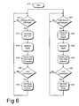
- FIG. 6is a flowchart illustrating operations in an exemplary process for originating calls from a customer premise.
- FIG. 7is a schematic illustration of an exemplary computing system.
- Described hereinare exemplary network architectures and methods for telephone call routing.
- the methods described hereinmay be embodied as logic instructions on a computer-readable medium. When executed on a processor, the logic instructions cause a general purpose computing device to be programmed as a special-purpose machine that implements the described methods.
- the processorwhen configured by the logic instructions to execute the methods recited herein, constitutes structure for performing the described methods.
- FIG. 1is a schematic illustration of an exemplary network architecture for telephone call routing.
- a customer premise 150is connected to the PSTN 112 by a dedicated communication line 124 with a central office switch 122 .
- PSTN 112generally represents the circuit-switched public switched telephone network that carries the vast majority of voice communication.
- the central office 120represents a central office facility operated by a local exchange carrier, i.e., an ILEC or a CLEC.
- the dedicated communication line 124may be a POTS telephone line embodied as a conventional copper wire “local loop” or may include multiple segments of differing physical media.
- Central office switch 122may be implemented as a Class 5 (CL5) switch.
- CL5 switchesare typically owned and operated by the Local Exchange Carrier (LEC).
- LECLocal Exchange Carrier
- a CL5 switchhas a plurality of physical ports that are referred to as interface Directory Numbers (iDNs).
- the portsrepresent telephone numbers (or lines) provisioned on the Class 5 switch. These lines may be grouped into Feature Groups based on the services that are provisioned in the respective switch 122 , such as call-waiting, three-way calling, etc.
- the CL5 switch 122may be connected to other CL5 switches via transmission circuits so that inter-office trunking between the switches is possible.
- Central Office 120may also include an Intelligent Service Control Point (ISCP) that provides call signaling via, e.g., Signaling System No. 7 (SS7) signaling.
- ISCPIntelligent Service Control Point
- SS7Signaling System No. 7
- Customer premise 150also includes a broadband gateway 152 that provides a broadband connection to a data network 140 , which may be embodied as the public Internet or a private data network.
- Broadband gateway 152may be implemented as a Digital Subscriber Link (DSL) gateway.
- DSLDigital Subscriber Link
- broadband gateway 152may be embodied as a cable modem.
- DSL signal architecturesgenerally denoted as xDSL, allow digital distribution of combined broadband video and data services using physical plant conventionally used for traditional narrowband voice transmissions.
- ADSLAsymmetric digital subscriber line
- UDPunshielded twisted pair
- ADSLis capable of providing a downstream bandwidth of about 1.5 Mbps-8 Mbps, and an upstream bandwidth of about 16 Kbps-64 Kbps across loop distances ranging from about 3.7 km-5.5 km.
- High bit rate digital subscriberprovides a symmetric, high-performance connection over a shorter loop, and typically require two or three copper twisted pairs.
- HDSLis capable of providing both upstream and downstream bandwidth of about 1.5 Mbps, over loop distances of up to about 3.7 km.
- Single line digital subscriber lineprovides a symmetric connection that matches HDSL performance using a single twisted pair, but operates over a shorter loop of up to about 3.0 km.
- VDSLVery high speed Digital Subscriber Line
- VDSL servicesare typically implemented in an asymmetric form having a downstream transmission capability of about 52 Mbps over twisted pair copper wire arranged in local loops of 300 meters, 26 Mbps at 1,000 meters, and 13 Mbps at 1,500 meters. Upstream data rates in asymmetric implementations tend to range from about 1.6 Mbps to about 2.3 Mbps.
- a typical distribution systemincludes a central office equipped with a host digital terminal (HDT) and arranged to operate as a hub between multiple video information providers (VIPs)/digital service providers (DSPs) and customer residential dwellings.
- VIPsvideo information providers
- DSPsdigital service providers
- optic fibere.g., OC-3c and OC-12c
- USAMuniversal system access multiplexer
- NIDnetwork interface device
- a dedicated VDSL loopextends between the NID and an individual customer residence using an existing POTS or telephone system twisted pair wire, and a customer interface device, such as a residential gateway or set top box, provides a connection point for a customer television or personal computer.
- a fiber-to-the-curb (FTTC) type distribution systemis similar except that a broadband network unit (BNU) is used in place of the USAM, and coaxial cable is used to connect the BNU, NID, and set top box.
- BNUbroadband network unit
- a data network service provider 130 connected to the central office switch 122 via a communication link 126operates a voice over internet protocol (VoIP) service.
- communication link 126may be embodied as a dedicated data link such as, e.g., a local area network (LAN) or a wide area network (WAN).
- Data network service provider 130operates a VoIP gateway 132 that is connected to the central office switch 122 .
- the VoIP gatewayprovides the interface between the VoIP communications devices and the PSTN network.
- the VoIP gateway 132receives calls from the central office switch 122 over data connection 126 and routes the calls over data network 140 .
- callsmay be routed over a local IP network 134 before routing to data network 140 .
- Data network service provider 130may also operate a feature server 136 .
- dedicated communication line 124is connected to a plurality telephones 158 a , 158 b , 158 c , 158 d .
- broadband gateway 152enables data connections 154 a , 154 b , 154 c with a plurality of telephones 158 a , 158 b , 158 c .
- the data connections 154 a , 154 b , 154 cmay be implemented using the existing telephone wiring using, e.g, an HPNA network, a LAN, or the like.
- the data connections 154 a , 154 b , 154 cmay be implemented over a wireless interface such as, e.g., an 802.11a, 802.11b, 802.11g, or Bluetooth network.
- a wireless interfacesuch as, e.g., an 802.11a, 802.11b, 802.11g, or Bluetooth network.
- the particular transmission medium used to implement data connections 154 a , 154 b , 154 cis not critical.
- FIG. 2is a schematic illustration of an exemplary customer premise network architecture.
- a conventional POTS telephone local loop 230is connected to the customer premise Network Interface device (NID) 210 .
- NIDNetwork Interface device
- Within the customer premise internal wiring 232connects a plurality of phone jacks 212 a , 212 b , 212 c , 212 d to the NID 210 .
- ADSL gateway 214is connected to phone jack 212 a .
- DSL gateway 214may be used to provide a broadband connection to one or more personal computers 220 .
- One or more conventional telephones 222may be connected to one or more phone jacks 212 b via a conventional DSL filter 216 .
- VoIP phones 224 a , 224 bmay be connected to one or more phone jacks 212 c , 212 d via respective VoIP adapters 218 a , 218 b .
- VoIP phones 224 a , 224 b and VoIP adapters 218 a , 218 bare commercially available from multiple vendors (e.g., 2Wire).
- the architecture illustrated in FIG. 2provides data connections between DSL gateway 214 and VoIP phones 224 a , 224 b that enable VoIP phones to conduct VoIP telephone calls.
- the data connectionmay be established over a HPNA Ethernet network.
- Many VoIP phones 224 a , 224 bare also capable of conducting POTS telephone calls.
- VoIP phones 224 a , 224 bmay include logic circuitry that enables a user to select POTS telephone service, rather than VoIP service.
- VoIP adapters 218 a , 218 bmay include logic circuitry that detects a failure in the data network and, in response thereto, fails-over to POTS telephony.
- FIG. 3is a flowchart illustrating call routing operations performed by a central office switch 122 .
- the call routing operationsmay be used to transmit one or more POTS telephone call received from the PSTN 110 to the customer premise. Further, the call routing operations may be used to transmit multiple calls to the same telephone number at the customer premise, such that two or more telephones having the same telephone number at the customer premise can conduct separate phone calls simultaneously.
- FIG. 3enable a central office switch 122 to connect a POTS telephone call from the PSTN to a telephone at a subscriber premise 150 .
- the central office switchreceives the POTS telephone call directed to a telephone number associated with dedicated communication line 124 and routes the POTS call to a telephone connected to the dedicated communication line 124 if the dedicated communication line 124 is available. If the dedicated communication line 124 is unavailable, then the central office switch forwards the call to a data network for routing to a VoIP telephone connected to the dedicated voice connection.
- the central office switch 122receives an incoming call from the PSTN 110 that is directed to the telephone number associated with the dedicated communication line 124 .
- an incoming callmay be preceded by call signaling pursuant to an intelligent signaling system such as, e.g., the SS7 signaling system.
- the operations of FIG. 3may be initiated by receipt of call signaling, rather than the call itself.
- the central office switchdetermines whether all phones associated with the telephone number are unavailable. A phone may be unavailable if it is off-hook, disconnected from the network, or without electrical power. If all phones associated with the telephone number are busy, then at operation 314 the central office switch returns a busy signal to the calling party, and at operation 316 the central office switch 122 returns to normal operations to process another call.
- Central office switch 122may transmit an electrical signal (e.g., a voltage pulse) across dedicated communication line 124 that causes the telephone(s) connected to dedicated communication line 124 to ring. If, at operation 322 , the call is answered then the central office switch sets the status of the dedicated communication line to busy. By contrast, if at operation 322 the call is not answered, then control passes to operation 332 and the central office switch 122 returns to normal operations to process another call.
- an electrical signale.g., a voltage pulse
- central office switch 122transmits a signal via communication link 126 to data network service provider 130 requesting that the call be completed via the data network service provider 130 .
- the signalincludes the telephone number associated with the dedicated voice connection. Operational details of connecting the call over the data network are described below in FIG. 4 and the accompanying text.
- the controlsimply passes to operation 332 or forwards to voice mail and the central office switch 122 returns to normal operations to process another call.
- FIG. 3enable the central office switch 122 to complete a call from the PSTN 110 to the user premise 150 via the dedicated communication line 124 , if the dedicated communication line 124 is available. If it is unavailable, then the call is routed to the user premise 150 via the data network service provider 130 .
- FIG. 4is a flowchart illustrating call routing operations performed by data network service provider 130 .
- the operations of FIG. 4enable a data network service provider to connect a POTS telephone call transmitted across the PSTN 112 .
- the data networkreceives a signal from the telephone network that identifies the telephone number associated with the dedicated communication line 124 .
- the data network service provider 130establishes a data connection between a VoIP gateway in the data network and a VoIP telephone connected to the dedicated communication line 124 and transmits a ring signal to the VoIP telephone.
- the data network service providerreceives a call signal from the central office switch identifying the telephone number at the customer premise 150 and requesting the data network service provider 130 to complete the call.
- the call signalmay be processed by the VoIP gateway 132 .
- the call signalmay be processed by feature server 136 , or another server operated by the data network service provider 130 .
- the data network service providerdetermines whether one or more VoIP phones such as VoIP phones 224 a , 224 b are available. If no VoIP phones are available, then control passes to operation 414 and the data network service provider returns a signal to the central office switch 122 indicating that no phones are available, i.e., a busy signal. The central office switch 122 may then return a busy signal to the calling party.
- the data network service provider 130returns to normal operations to process another call or otherwise establish another data connection.
- the data network service providerpasses the call status back to the central office switch 122 .
- the central office switch 122(or a computing device associated with the central office switch 122 ) records the status of the VoIP phone(s) in a suitable memory location.
- the central office switch(or associated computing device) may consult this table in operation 312 to determine whether all phones associated with a particular telephone number are available.
- the data network service provider 130monitors the call status to determine whether the call has been terminated (operation 426 ). When the call is terminated, the data network service provider 130 sets resets the flag to indicate that the VoIP phone is now available. In an exemplary implementation this flag is forwarded to the central office switch 122 for recordation in a memory location, as described above.
- the data network service provider 130returns to normal operations to process another call or otherwise establish another data connection.
- the network architecture of FIGS. 1-2 and the methods of FIGS. 3-4enable a traditional POTS telephone service provider and a data network service provider to cooperate to provide expanded telephony service to a subscriber premise 150 .
- the servicepermits a subscriber to leverage the traditional POTS telephone number associated with the dedicated communication line 124 between the central office switch and the customer premise to virtually any number of additional telephones.
- a first incoming callis routed to the subscriber premise over the dedicated communication line 124 in accordance with conventional POTS telephony.
- a second (or subsequent) call directed to the telephone number associated with the dedicated communication line 124 received while the dedicated communication line 124 is busymay be routed to one or more available VoIP phones 224 a , 224 b at the customer premise via the data network service provider 130 . Accordingly, a call placed to the telephone number associated with the dedicated communication line 124 will not receive a busy signal, provided at least one telephone at the customer premise 150 is available.
- FIG. 5is a flowchart illustrating alternate call routing operations performed by a central office switch 122 .
- the central office switch 122receives an incoming call from the PSTN 110 that is directed to the telephone number associated with the dedicated communication line 124 .
- Operations 510 - 516are analogous to operations 310 - 316 . The reader is referred to the text above describing these operations.
- central office switch 122transmits a signal via communication link 126 to data network service provider 130 requesting that the call be completed via the data network service provider 130 .
- the signalincludes the telephone number associated with the dedicated voice connection.
- the data network service provider 130may connect the call over the data network as described above in FIG. 4 and the accompanying text.
- Central office switch 122may transmit an electrical signal (e.g., a voltage pulse) across dedicated communication line 124 that causes the telephone(s) connected to dedicated communication line 124 to ring. If, at operation 528 , the call is answered then the central office switch sets the status of the dedicated communication line to busy (operation 530 ). By contrast, if at operation 528 the call is not answered, then control passes to operation 532 and the central office switch 122 returns to normal operations to process another call.
- an electrical signale.g., a voltage pulse
- the network architecture depicted in FIGS. 1-2also enables a subscriber to leverage the dedicated communication line 124 to originate multiple telephone calls from the single telephone number associated with the dedicated communication line 124 .
- the data network service providershares VoIP telephone status information with the central office switch 112 to allow the central office switch to monitor the status of the VoIP telephones at the subscriber premise.
- FIG. 6is a flowchart illustrating operations in an exemplary process for originating calls from a customer premise, such as customer premise 150 .
- the processstarts at operation 610 , and at operation 612 the central office switch 122 monitors the dedicated communication line 124 to determine whether a telephone connected to the dedicated communication line 124 transitioned from an on-hook state to an off-hook state.
- a telephone connected to the dedicated communication line 124is termed a “primary” telephone.
- VoIP telephones capable of operating in a conventional POTS modemay function as a primary telephone for the purposes of FIG. 6 .
- the central office switch 122receives a plurality of digits from the primary telephone (e.g., as DTMF signals) and at operation 618 the central office switch 122 originates a call over the PSTN using the received digits.
- the central office switch 122may also execute conventional error processing routines to determine whether the received digits correspond to a valid telephone number.
- the VoIP telephonesare blocked from accessing the call originated from the primary telephone. This implementation is particularly useful when the VoIP phones are also capable of operating as conventional POTS telephones. This blocking may be accomplished in the VoIP adapter 218 a , 218 b by severing a logical connection between the VoIP telephone(s) and the dedicated communication line 124 .
- the central office switchsets the status of the dedicated voice line to busy. The status may be stored in a suitable memory location associated with the central office switch, or with a computing device (e.g., a server) associated therewith.
- the data network service provider 130monitors the VoIP phone(s) for a call request.
- a call requestmay be embodied as a service request from a VoIP telephone. If the VoIP phone is designed to emulate a conventional POTS telephone, then the service request may be triggered by a transition of the VoIP phone from an on-hook state to an off-hook state.
- the active signalmay emulate a conventional POTS telephony dial tone, while in other implementations the active signal may comprise a pre-recorded message indicating that the VoIP phone is operational or other signaling indicia.
- the data network service providerreceives digits that the caller enters into the VoIP telephone and at operation 630 the data network service provider initiates the call over the data network 140 using the received digits.
- the callmay be routed to the called number via the PSTN 112 .
- the data network service providermay forward the call to the central office switch 122 via communication link 126 .
- the callmay be carried to the destination entirely by a data network such as data network 140 .
- the data network service providersets the status of the VoIP phone to busy.
- this status informationis forwarded to the central office switch 122 , which may record the status in a suitable memory location.
- This central office switchuses this status information when routing incoming calls, as described in connection with operations 312 , 318 , and 412 .
- the data network service providerresets the VoIP phone status to available.
- This status informationmay also be passed to the central office switch 112 , which can update its data tables accordingly.
- the data network service provider 130cooperates with the telephone network central office 120 to enable a subscriber at customer premise 150 to leverage the single telephone number associated with the dedicated communication line 124 to originate multiple telephone calls from the subscriber premise 150 .
- FIG. 7shows components of an exemplary server computer, referred by to reference numeral 700 .
- the components shown in FIG. 7are only examples, and are not intended to suggest any limitation as to the scope of the functionality of the invention; the invention is not necessarily dependent on the features shown in FIG. 7 .
- various different general purpose or special purpose computing system configurationscan be used.
- Examples of well known computing systems, environments, and/or configurations that may be suitable for use with the inventioninclude, but are not limited to, personal computers, server computers, hand-held or laptop devices, multiprocessor systems, microprocessor-based systems, set top boxes, programmable consumer electronics, network PCs, minicomputers, mainframe computers, distributed computing environments that include any of the above systems or devices, and the like.
- program modulesinclude routines, programs, objects, components, data structures, etc. that perform particular tasks or implement particular abstract data types. Tasks might also be performed by remote processing devices that are linked through a communications network.
- program modulesmay be located in both local and remote computer storage media.
- the instructions and/or program modulesare stored at different times in the various computer-readable media that are either part of the computer or that can be read by the computer.
- Programsare typically distributed, for example, on floppy disks, CD-ROMs, DVD, or some form of communication media such as a modulated signal. From there, they are installed or loaded into the secondary memory of a computer. At execution, they are loaded at least partially into the computer's primary electronic memory.
- the invention described hereinincludes these and other various types of computer-readable media when such media contain instructions programs, and/or modules for implementing the steps described below in conjunction with a microprocessor or other data processors.
- the inventionalso includes the computer itself when programmed according to the methods and techniques described below.
- programs and other executable program componentssuch as the operating system are illustrated herein as discrete blocks, although it is recognized that such programs and components reside at various times in different storage components of the computer, and are executed by the data processor(s) of the computer.
- the components of computer 700may include, but are not limited to, a processing unit 704 , a system memory 706 , and a system bus 708 that couples various system components including the system memory to the processing unit 704 .
- the system bus 708may be any of several types of bus structures including a memory bus or memory controller, a peripheral bus, and a local bus using any of a variety of bus architectures.
- bus architecturesinclude Industry Standard Architecture (ISA) bus, Micro Channel Architecture (MCA) bus, Enhanced ISA (EISAA) bus, Video Electronics Standards Association (VESA) local bus, and Peripheral Component Interconnect (PCI) bus also known as the Mezzanine bus.
- Computer 700typically includes a variety of computer-readable media.
- Computer-readable mediacan be any available media that can be accessed by computer 700 and includes both volatile and nonvolatile media, removable and non-removable media.
- Computer-readable mediamay comprise computer storage media and communication media.
- Computer storage mediaincludes volatile and nonvolatile, removable and non-removable media implemented in any method or technology for storage of information such as computer-readable instructions, data structures, program modules, or other data.
- Computer storage mediaincludes, but is not limited to, RAM, ROM, EEPROM, flash memory or other memory technology, CD-ROM, digital versatile disks (DVD) or other optical disk storage, magnetic cassettes, magnetic tape, magnetic disk storage or other magnetic storage devices, or any other medium which can be used to store the desired information and which can be accessed by computer 700 .
- Communication mediatypically embodies computer-readable instructions, data structures, program modules or other data in a modulated data signal such as a carrier wave or other transport mechanism and includes any information delivery media.
- modulated data signalmeans a signal that has one or more if its characteristics set or changed in such a manner as to encode information in the signal.
- communication mediaincludes wired media such as a wired network or direct-wired connection and wireless media such as acoustic, RF, infrared and other wireless media. Combinations of any of the above should also be included within the scope of computer readable media.
- the system memory 706includes computer storage media in the form of volatile and/or nonvolatile memory such as read only memory (ROM) 710 and random access memory (RAM) 712 .
- ROMread only memory
- RAMrandom access memory
- BIOSbasic input/output system
- RAM 712typically contains data and/or program modules that are immediately accessible to and/or presently being operated on by processing unit 704 .
- FIG. 7illustrates operating system 716 , application programs 718 , other program modules 720 , and program data 722 .
- the computer 700may also include other removable/non-removable, volatile/nonvolatile computer storage media.
- FIG. 7illustrates a hard disk drive 724 that reads from or writes to non-removable, nonvolatile magnetic media, a magnetic disk drive 726 that reads from or writes to a removable, nonvolatile magnetic disk 728 , and an optical disk drive 730 that reads from or writes to a removable, nonvolatile optical disk 732 such as a CD ROM or other optical media.
- removable/non-removable, volatile/nonvolatile computer storage mediathat can be used in the exemplary operating environment include, but are not limited to, magnetic tape cassettes, flash memory cards, digital versatile disks, digital video tape, solid state RAM, solid state ROM, and the like.
- the hard disk drive 724is typically connected to the system bus 708 through a non-removable memory interface such as data media interface 734 , and magnetic disk drive 726 and optical disk drive 730 are typically connected to the system bus 708 by a removable memory interface.
- hard disk drive 724is illustrated as storing operating system 716 ′, application programs 718 ′, other program modules 720 ′, and program data 722 ′. Note that these components can either be the same as or different from operating system 716 , application programs 718 , other program modules 720 , and program data 722 . Operating system 716 , application programs 718 , other program modules 720 , and program data 722 are given different numbers here to illustrate that, at a minimum, they are different copies.
- a usermay enter commands and information into the computer 700 through input devices such as a keyboard 736 , a mouse, trackball, or touch pad.
- Other input devicesmay include a microphone, joystick, game pad, satellite dish, scanner, or the like.
- I/Oinput/output
- a monitor 744 or other type of display deviceis also connected to the system bus 708 via an interface, such as a video adapter 746 .
- computersmay also include other peripheral output devices (e.g., speakers) and one or more printers, which may be connected through the I/O interface 742 .
- the computermay operate in a networked environment using logical connections to one or more remote computers, such as a remote computing device 750 .
- the remote computing device 750may be a personal computer, a server, a router, a network PC, a peer device or other common network node, and typically includes many or all of the elements described above relative to computer 700 .
- the logical connections depicted in FIG. 7include a local area network (LAN) 752 and a wide area network (WAN) 754 .
- LANlocal area network
- WANwide area network
- the WAN 754 shown in FIG. 7is the Internet, the WAN 754 may also include other networks.
- Such networking environmentsare commonplace in offices, enterprise-wide computer networks, intranets, and the like.
- the computer 700When used in a LAN networking environment, the computer 700 is connected to the LAN 752 through a network interface or adapter 756 . When used in a WAN networking environment, the computer 700 typically includes a modem 758 or other means for establishing communications over the Internet 754 .
- the modem 758which may be internal or external, may be connected to the system bus 708 via the I/O interface 742 , or other appropriate mechanism.
- program modules depicted relative to the computer 700may be stored in the remote computing device 750 .
- FIG. 7illustrates remote application programs 760 as residing on remote computing device 750 . It will be appreciated that the network connections shown are exemplary and other means of establishing a communications link between the computers may be used.
Landscapes
- Engineering & Computer Science (AREA)
- Signal Processing (AREA)
- General Engineering & Computer Science (AREA)
- Computer Networks & Wireless Communication (AREA)
- Telephonic Communication Services (AREA)
Abstract
Description
Claims (20)
Priority Applications (2)
| Application Number | Priority Date | Filing Date | Title |
|---|---|---|---|
| US10/894,698US8184793B2 (en) | 2004-07-20 | 2004-07-20 | Multi-line telephone calling |
| US13/451,416US9042538B2 (en) | 2004-07-20 | 2012-04-19 | Multi-line telephone calling |
Applications Claiming Priority (1)
| Application Number | Priority Date | Filing Date | Title |
|---|---|---|---|
| US10/894,698US8184793B2 (en) | 2004-07-20 | 2004-07-20 | Multi-line telephone calling |
Related Child Applications (1)
| Application Number | Title | Priority Date | Filing Date |
|---|---|---|---|
| US13/451,416ContinuationUS9042538B2 (en) | 2004-07-20 | 2012-04-19 | Multi-line telephone calling |
Publications (2)
| Publication Number | Publication Date |
|---|---|
| US20060018452A1 US20060018452A1 (en) | 2006-01-26 |
| US8184793B2true US8184793B2 (en) | 2012-05-22 |
Family
ID=35657127
Family Applications (2)
| Application Number | Title | Priority Date | Filing Date |
|---|---|---|---|
| US10/894,698Active2029-07-08US8184793B2 (en) | 2004-07-20 | 2004-07-20 | Multi-line telephone calling |
| US13/451,416Expired - LifetimeUS9042538B2 (en) | 2004-07-20 | 2012-04-19 | Multi-line telephone calling |
Family Applications After (1)
| Application Number | Title | Priority Date | Filing Date |
|---|---|---|---|
| US13/451,416Expired - LifetimeUS9042538B2 (en) | 2004-07-20 | 2012-04-19 | Multi-line telephone calling |
Country Status (1)
| Country | Link |
|---|---|
| US (2) | US8184793B2 (en) |
Cited By (1)
| Publication number | Priority date | Publication date | Assignee | Title |
|---|---|---|---|---|
| US9042538B2 (en) | 2004-07-20 | 2015-05-26 | Qwest Communications International Inc. | Multi-line telephone calling |
Families Citing this family (9)
| Publication number | Priority date | Publication date | Assignee | Title |
|---|---|---|---|---|
| US20070036325A1 (en)* | 2005-07-19 | 2007-02-15 | Sbc Knowledge Ventures, L.P. | SS7 network having wireline and failover wireless SS7 links |
| US20070027891A1 (en)* | 2005-08-01 | 2007-02-01 | Christiane Schauerte | System and method for providing listing check functionality |
| US11769010B2 (en)* | 2005-10-06 | 2023-09-26 | Celcorp, Inc. | Document management workflow for redacted documents |
| US20070195752A1 (en)* | 2006-02-22 | 2007-08-23 | Lucent Technologies Inc. | System and method for handling call redirection and multi call destination failures |
| US8165135B2 (en)* | 2006-05-05 | 2012-04-24 | At&T Intellectual Property I, L.P. | Methods, computer networks, and computer program products that facilitate providing broadband services wirelessly to third party users via a mesh network of customer premise equipment |
| US8533078B2 (en)* | 2007-12-21 | 2013-09-10 | Celcorp, Inc. | Virtual redaction service |
| WO2016044332A1 (en)* | 2014-09-15 | 2016-03-24 | Reliance Jio Infocomm Usa, Inc. | Extending communication services to a consumption device using a proxy device |
| CN106506878B (en)* | 2016-10-17 | 2019-11-19 | 深圳震有科技股份有限公司 | A realization method and realization system for directly initiating a new call without hanging up |
| US11113800B2 (en)* | 2017-01-18 | 2021-09-07 | Nvidia Corporation | Filtering image data using a neural network |
Citations (77)
| Publication number | Priority date | Publication date | Assignee | Title |
|---|---|---|---|---|
| US5206901A (en) | 1991-12-23 | 1993-04-27 | At&T Bell Laboratories | Method and apparatus for alerting multiple telephones for an incoming call |
| US5572583A (en) | 1992-04-17 | 1996-11-05 | Bell Atlantic | Advanced intelligent network with intelligent peripherals interfaced to the integrated services control point |
| US5583920A (en) | 1992-04-17 | 1996-12-10 | Bell Atlantic | Intelligent peripheral in video dial tone network |
| US5732130A (en) | 1994-10-27 | 1998-03-24 | Ericsson Inc. | System and method of providing enhanced subscriber services in a multi-node telecommunications network |
| US5764743A (en)* | 1995-10-20 | 1998-06-09 | Motorola, Inc. | Method of controlling operation of a multi-line telephone apparatus |
| US5805587A (en) | 1995-11-27 | 1998-09-08 | At&T Corp. | Call notification feature for a telephone line connected to the internet |
| US5848132A (en) | 1996-03-14 | 1998-12-08 | British Telecommunications Public Limited Company | Telecommunications network having resident ability to pre-book scheduled call back services |
| US5905792A (en) | 1997-02-10 | 1999-05-18 | Genesys Telecommunications Laboratories, Inc. | External positivistic forward transfer in call routing systems |
| US5930338A (en) | 1996-02-20 | 1999-07-27 | Solopoint, Inc. | Method for handling incoming calls on a pots telephone line to a user's premises |
| US5953322A (en) | 1997-01-31 | 1999-09-14 | Qualcomm Incorporated | Cellular internet telephone |
| US6055306A (en) | 1997-03-19 | 2000-04-25 | International Business Machines Corp. | Suppression of call answer supervision in a telephone network by an intelligent peripheral |
| US6075783A (en) | 1997-03-06 | 2000-06-13 | Bell Atlantic Network Services, Inc. | Internet phone to PSTN cellular/PCS system |
| US6118864A (en) | 1997-12-31 | 2000-09-12 | Carmel Connection, Inc. | System and method for providing communication on a wide area network |
| US6125177A (en) | 1997-09-15 | 2000-09-26 | Nortel Networks Corporation | Telephone communications network with enhanced signaling and call routing |
| US6141341A (en)* | 1998-09-09 | 2000-10-31 | Motorola, Inc. | Voice over internet protocol telephone system and method |
| US6175562B1 (en) | 1997-04-29 | 2001-01-16 | Intervoice Limited Partnership | Switchless call processing |
| US6205211B1 (en) | 1998-08-04 | 2001-03-20 | Transnexus, Llc | Internet telephony call pricing center |
| US6282192B1 (en) | 2000-01-27 | 2001-08-28 | Cisco Technology, Inc. | PSTN fallback using dial on demand routing scheme |
| US20010028642A1 (en) | 2000-03-29 | 2001-10-11 | Veschi Robert A. | Method and system for routing calls from a standard telephone device to a voice over internet protocol network |
| US6304565B1 (en) | 1998-05-20 | 2001-10-16 | At&T Corp. | Method of completing long distance pots calls with IP telephony endpoints |
| US20010032270A1 (en) | 2000-03-20 | 2001-10-18 | Chan-Kyu Koo | System and method for multi-telecommunication local IP network |
| US20020002041A1 (en) | 2000-04-15 | 2002-01-03 | Lindgren Hans Ake | Telecommunications system |
| US6351464B1 (en) | 1999-09-20 | 2002-02-26 | Mci Worldcom, Inc. | Virtual second line hybrid network communication system |
| US6353611B1 (en) | 1995-11-27 | 2002-03-05 | At&T Corp. | Call waiting feature for a telephone line connected to the internet |
| US6363424B1 (en) | 1999-09-01 | 2002-03-26 | Lucent Technologies, Inc. | Reuse of services between different domains using state machine mapping techniques |
| US6381459B1 (en) | 1998-10-22 | 2002-04-30 | Telefonaktiebolaget Lm Ericsson (Publ) | Mobile communication system, method and alternative network gateway unit for processing a call |
| US6404782B1 (en)* | 1998-09-21 | 2002-06-11 | Lucent Technologies Inc. | Method and apparatus for signaling over packet-based systems |
| US6421424B1 (en) | 2000-06-05 | 2002-07-16 | International Business Machines Corp. | Client simulator and method of operation for testing PSTN-to-IP network telephone services for individual & group internet clients prior to availability of the services |
| US6426955B1 (en) | 1997-09-16 | 2002-07-30 | Transnexus, Inc. | Internet telephony call routing engine |
| US6430281B1 (en) | 1996-03-14 | 2002-08-06 | British Telecommunications Public Limited Company | Intelligent telecommunications network providing automated call booking, call reconnection and diary booking services |
| US6438220B1 (en) | 2000-03-30 | 2002-08-20 | Worldcom, Inc. | Method and apparatus for internet-based telephone access to prepaid card and pin systems |
| US6480588B1 (en) | 1999-11-08 | 2002-11-12 | Worldcom, Inc. | Methods for providing prepaid telephony service via an internet protocol network system |
| US6487283B2 (en) | 1998-08-04 | 2002-11-26 | Transnexus, Inc. | Pricing center for internet protocol routed transactions |
| US20030012178A1 (en) | 2001-04-06 | 2003-01-16 | Mussman Harry Edward | Alternate routing of voice communication in a packet-based network |
| US6519252B2 (en) | 1997-12-31 | 2003-02-11 | Ericsson Inc. | System and method for connecting a call to a mobile subscriber connected to the Internet |
| US20030048795A1 (en) | 2001-09-13 | 2003-03-13 | Alcatel | Gateway between digital signal transmission networks |
| US6535521B1 (en) | 1999-06-29 | 2003-03-18 | 3Com Corporation | Distributed speech coder pool system with front-end idle mode processing for voice-over-IP communications |
| US20030072272A1 (en) | 2001-10-17 | 2003-04-17 | Atsuko Koide | IP network communication device with facsimile communication function |
| US20030095539A1 (en) | 2000-01-07 | 2003-05-22 | Feuer Donald S | Method and Apparatus for Interfacing a Public Switched Telephone Network and an Internet Protocol Network for Multi-Media Communication |
| US20030095541A1 (en)* | 1997-07-25 | 2003-05-22 | Chang Gordon K. | Apparatus and method for integrated voice gateway |
| US6574469B1 (en) | 2000-05-09 | 2003-06-03 | Telefonaktiebolaget L M Ericsson (Publ) | System and method of minimizing the number of voice transcodings during a conference call in a packet-switched network |
| US6584108B1 (en) | 1998-09-30 | 2003-06-24 | Cisco Technology, Inc. | Method and apparatus for dynamic allocation of multiple signal processing resources among multiple channels in voice over packet-data-network systems (VOPS) |
| US6594253B1 (en) | 1998-09-29 | 2003-07-15 | Ericsson Inc. | System and method for mobility management for an internet telephone call to a mobile terminal |
| US20030143978A1 (en) | 2002-01-18 | 2003-07-31 | Boston Communications Group, Inc. | Wireless telephone call processing |
| US6606668B1 (en) | 1994-02-16 | 2003-08-12 | Priority Call Management, Inc. | System and method for least cost routing and managing multiple gatekeepers on a packet switched network |
| US20030154408A1 (en) | 2002-02-13 | 2003-08-14 | Yanong Zhu | Method and apparatus for secured unified public communication network based on IP and common channel signaling |
| US20030154083A1 (en) | 2002-02-11 | 2003-08-14 | Paul Kobylevsky | Method and apparatus for providing prescription services using voice recognition |
| US6614774B1 (en) | 1998-12-04 | 2003-09-02 | Lucent Technologies Inc. | Method and system for providing wireless mobile server and peer-to-peer services with dynamic DNS update |
| US6614781B1 (en)* | 1998-11-20 | 2003-09-02 | Level 3 Communications, Inc. | Voice over data telecommunications network architecture |
| US6625258B1 (en) | 1999-12-27 | 2003-09-23 | Nortel Networks Ltd | System and method for providing unified communication services support |
| US20030179743A1 (en) | 2001-12-18 | 2003-09-25 | Bosik Barry S. | Call management method responsive to network presence |
| US20030187926A1 (en) | 2000-12-18 | 2003-10-02 | Juha Karjanlahti | Ip based voice communication in a mobile communications system |
| US20030191647A1 (en) | 2002-04-05 | 2003-10-09 | Kam David M. | Method & system for managing web pages, and telecommunications via multilingual keywords and domains |
| US20030193696A1 (en) | 2002-01-24 | 2003-10-16 | Dominic Walker | Voice and fax over IP call establishment in a communications network |
| US20030202507A1 (en) | 2002-04-30 | 2003-10-30 | Minoru Nishida | VoIP network system |
| US20030210697A1 (en) | 2000-09-29 | 2003-11-13 | Mathieu Mercier | Auto encapsulation detection |
| US20030210677A1 (en) | 2002-05-10 | 2003-11-13 | Grove Vincent T. | Host-based device to terminate a modem relay channel directly to an IP network |
| US6650740B1 (en) | 1999-02-26 | 2003-11-18 | Bellsouth Intellectual Property Cororation | Methods and systems for enabling a reply call to a voice mail message |
| US6654348B1 (en) | 1999-12-27 | 2003-11-25 | Cisco Technology, Inc. | Modem pass through for remote testing |
| US20030219011A1 (en) | 2002-05-24 | 2003-11-27 | Dong-Sik Han | Head end apparatus for media gateway control protocol type voice over internet protocol call service |
| US20030227907A1 (en) | 2002-06-08 | 2003-12-11 | Gil-Young Choi | Apparatus for providing QoS of VoIP traffic on IP router and forwarding method therefor |
| US6665395B1 (en) | 1998-12-11 | 2003-12-16 | Avaya Technology Corp. | Automatic call distribution system using computer network-based communication |
| US20030235182A1 (en) | 2002-06-21 | 2003-12-25 | Mcmullin Rick | Virtual key system |
| US20040008717A1 (en) | 2002-07-12 | 2004-01-15 | Baypackets, Inc. | Fault tolerant correlation engine method and system for telecommunications networks |
| US20040008824A1 (en) | 2001-05-10 | 2004-01-15 | General Instrument Corporation | Extendable call agent simulator |
| US20040017802A1 (en) | 2002-05-07 | 2004-01-29 | Globespan Virata Inc. | Method and system for preventing data loss in a real-time computer system |
| US20040030785A1 (en) | 2002-08-07 | 2004-02-12 | Allied Telesis K.K. | Voice communication system and its method |
| US6792097B2 (en)* | 1999-04-14 | 2004-09-14 | Vocaldata, Inc. | System and method for implementing telephony call control via a set of components that communicate with each other via a unique telephony protocol |
| US20050190756A1 (en) | 2004-02-26 | 2005-09-01 | Mundra Satish Kumar M. | RTP payload for voice band data transmission |
| US20060018448A1 (en) | 2004-07-20 | 2006-01-26 | Qwest Communications International Inc. | Routing telephone calls via a data network |
| US20060018449A1 (en) | 2004-07-20 | 2006-01-26 | Qwest Communications International Inc. | Telephone call routing |
| US20060018310A1 (en) | 2004-07-20 | 2006-01-26 | Qwest Communications International Inc. | Data network call routing |
| US7016675B1 (en) | 1999-09-27 | 2006-03-21 | 3Com Corporation | System and method for controlling telephone service using a wireless personal information device |
| US20060077971A1 (en) | 2003-02-14 | 2006-04-13 | Brian Fowler | Internet telephony network and methods for using the same |
| US7061901B1 (en) | 1997-03-04 | 2006-06-13 | Way2Call Communications Ltd. | Data network and PSTN telephony system |
| US7103167B2 (en) | 2002-05-20 | 2006-09-05 | Callwave, Inc. | Systems and methods for call screening |
| US7336649B1 (en) | 1995-12-20 | 2008-02-26 | Verizon Business Global Llc | Hybrid packet-switched and circuit-switched telephony system |
Family Cites Families (7)
| Publication number | Priority date | Publication date | Assignee | Title |
|---|---|---|---|---|
| US6633635B2 (en)* | 1999-12-30 | 2003-10-14 | At&T Corp. | Multiple call waiting in a packetized communication system |
| JP4068780B2 (en)* | 2000-02-24 | 2008-03-26 | 富士通株式会社 | COMMUNICATION STATUS NOTIFICATION DEVICE, COMMUNICATION STATUS DISPLAY DEVICE, COMMUNICATION STATUS NOTIFICATION METHOD, AND MEDIUM CONTAINING COMMUNICATION STATUS NOTIFICATION PROGRAM IN VoIP COMMUNICATION SYSTEM |
| US6956933B2 (en)* | 2002-01-11 | 2005-10-18 | Thomson Licensing | Directory delivery system and method for a digital subscriber line modem |
| US20030167926A1 (en)* | 2002-03-06 | 2003-09-11 | Littrell Dennis Albert | Portable air cleaning, heating, and cooling apparatus |
| US20040006717A1 (en)* | 2002-07-08 | 2004-01-08 | Gunter Plappert | Data preservation |
| CA2483123A1 (en)* | 2003-09-30 | 2005-03-30 | At&T Corp. | Enhanced call notification service |
| US8184793B2 (en) | 2004-07-20 | 2012-05-22 | Qwest Communications International Inc. | Multi-line telephone calling |
- 2004
- 2004-07-20USUS10/894,698patent/US8184793B2/enactiveActive
- 2012
- 2012-04-19USUS13/451,416patent/US9042538B2/ennot_activeExpired - Lifetime
Patent Citations (82)
| Publication number | Priority date | Publication date | Assignee | Title |
|---|---|---|---|---|
| US5206901A (en) | 1991-12-23 | 1993-04-27 | At&T Bell Laboratories | Method and apparatus for alerting multiple telephones for an incoming call |
| US5572583A (en) | 1992-04-17 | 1996-11-05 | Bell Atlantic | Advanced intelligent network with intelligent peripherals interfaced to the integrated services control point |
| US5583920A (en) | 1992-04-17 | 1996-12-10 | Bell Atlantic | Intelligent peripheral in video dial tone network |
| US6606668B1 (en) | 1994-02-16 | 2003-08-12 | Priority Call Management, Inc. | System and method for least cost routing and managing multiple gatekeepers on a packet switched network |
| US5732130A (en) | 1994-10-27 | 1998-03-24 | Ericsson Inc. | System and method of providing enhanced subscriber services in a multi-node telecommunications network |
| US5764743A (en)* | 1995-10-20 | 1998-06-09 | Motorola, Inc. | Method of controlling operation of a multi-line telephone apparatus |
| US5805587A (en) | 1995-11-27 | 1998-09-08 | At&T Corp. | Call notification feature for a telephone line connected to the internet |
| US6353611B1 (en) | 1995-11-27 | 2002-03-05 | At&T Corp. | Call waiting feature for a telephone line connected to the internet |
| US7336649B1 (en) | 1995-12-20 | 2008-02-26 | Verizon Business Global Llc | Hybrid packet-switched and circuit-switched telephony system |
| US5930338A (en) | 1996-02-20 | 1999-07-27 | Solopoint, Inc. | Method for handling incoming calls on a pots telephone line to a user's premises |
| US5848132A (en) | 1996-03-14 | 1998-12-08 | British Telecommunications Public Limited Company | Telecommunications network having resident ability to pre-book scheduled call back services |
| US6430281B1 (en) | 1996-03-14 | 2002-08-06 | British Telecommunications Public Limited Company | Intelligent telecommunications network providing automated call booking, call reconnection and diary booking services |
| US5953322A (en) | 1997-01-31 | 1999-09-14 | Qualcomm Incorporated | Cellular internet telephone |
| US5905792A (en) | 1997-02-10 | 1999-05-18 | Genesys Telecommunications Laboratories, Inc. | External positivistic forward transfer in call routing systems |
| US7061901B1 (en) | 1997-03-04 | 2006-06-13 | Way2Call Communications Ltd. | Data network and PSTN telephony system |
| US6185204B1 (en) | 1997-03-06 | 2001-02-06 | Bell Atlantic Network Services, Inc. | Internet phone to PSTN cellular/PCS system |
| US6075783A (en) | 1997-03-06 | 2000-06-13 | Bell Atlantic Network Services, Inc. | Internet phone to PSTN cellular/PCS system |
| US6055306A (en) | 1997-03-19 | 2000-04-25 | International Business Machines Corp. | Suppression of call answer supervision in a telephone network by an intelligent peripheral |
| US6175562B1 (en) | 1997-04-29 | 2001-01-16 | Intervoice Limited Partnership | Switchless call processing |
| US20030095541A1 (en)* | 1997-07-25 | 2003-05-22 | Chang Gordon K. | Apparatus and method for integrated voice gateway |
| US20030095542A1 (en) | 1997-07-25 | 2003-05-22 | Chang Gordon K. | Apparatus and method for integrated voice gateway |
| US6125177A (en) | 1997-09-15 | 2000-09-26 | Nortel Networks Corporation | Telephone communications network with enhanced signaling and call routing |
| US6426955B1 (en) | 1997-09-16 | 2002-07-30 | Transnexus, Inc. | Internet telephony call routing engine |
| US6519252B2 (en) | 1997-12-31 | 2003-02-11 | Ericsson Inc. | System and method for connecting a call to a mobile subscriber connected to the Internet |
| US6118864A (en) | 1997-12-31 | 2000-09-12 | Carmel Connection, Inc. | System and method for providing communication on a wide area network |
| US6304565B1 (en) | 1998-05-20 | 2001-10-16 | At&T Corp. | Method of completing long distance pots calls with IP telephony endpoints |
| US6487283B2 (en) | 1998-08-04 | 2002-11-26 | Transnexus, Inc. | Pricing center for internet protocol routed transactions |
| US6205211B1 (en) | 1998-08-04 | 2001-03-20 | Transnexus, Llc | Internet telephony call pricing center |
| US6141341A (en)* | 1998-09-09 | 2000-10-31 | Motorola, Inc. | Voice over internet protocol telephone system and method |
| US6404782B1 (en)* | 1998-09-21 | 2002-06-11 | Lucent Technologies Inc. | Method and apparatus for signaling over packet-based systems |
| US6594253B1 (en) | 1998-09-29 | 2003-07-15 | Ericsson Inc. | System and method for mobility management for an internet telephone call to a mobile terminal |
| US6584108B1 (en) | 1998-09-30 | 2003-06-24 | Cisco Technology, Inc. | Method and apparatus for dynamic allocation of multiple signal processing resources among multiple channels in voice over packet-data-network systems (VOPS) |
| US6381459B1 (en) | 1998-10-22 | 2002-04-30 | Telefonaktiebolaget Lm Ericsson (Publ) | Mobile communication system, method and alternative network gateway unit for processing a call |
| US6614781B1 (en)* | 1998-11-20 | 2003-09-02 | Level 3 Communications, Inc. | Voice over data telecommunications network architecture |
| US20040022237A1 (en) | 1998-11-20 | 2004-02-05 | Level 3 Communications, Inc. | Voice over data telecommunications network architecture |
| US6614774B1 (en) | 1998-12-04 | 2003-09-02 | Lucent Technologies Inc. | Method and system for providing wireless mobile server and peer-to-peer services with dynamic DNS update |
| US6665395B1 (en) | 1998-12-11 | 2003-12-16 | Avaya Technology Corp. | Automatic call distribution system using computer network-based communication |
| US6650740B1 (en) | 1999-02-26 | 2003-11-18 | Bellsouth Intellectual Property Cororation | Methods and systems for enabling a reply call to a voice mail message |
| US20040037402A1 (en) | 1999-02-26 | 2004-02-26 | Maria Adamczyk | Methods and systems for enabling a reply call to voice mail message |
| US6792097B2 (en)* | 1999-04-14 | 2004-09-14 | Vocaldata, Inc. | System and method for implementing telephony call control via a set of components that communicate with each other via a unique telephony protocol |
| US6535521B1 (en) | 1999-06-29 | 2003-03-18 | 3Com Corporation | Distributed speech coder pool system with front-end idle mode processing for voice-over-IP communications |
| US6363424B1 (en) | 1999-09-01 | 2002-03-26 | Lucent Technologies, Inc. | Reuse of services between different domains using state machine mapping techniques |
| US6351464B1 (en) | 1999-09-20 | 2002-02-26 | Mci Worldcom, Inc. | Virtual second line hybrid network communication system |
| US7016675B1 (en) | 1999-09-27 | 2006-03-21 | 3Com Corporation | System and method for controlling telephone service using a wireless personal information device |
| US6480588B1 (en) | 1999-11-08 | 2002-11-12 | Worldcom, Inc. | Methods for providing prepaid telephony service via an internet protocol network system |
| US6625258B1 (en) | 1999-12-27 | 2003-09-23 | Nortel Networks Ltd | System and method for providing unified communication services support |
| US6654348B1 (en) | 1999-12-27 | 2003-11-25 | Cisco Technology, Inc. | Modem pass through for remote testing |
| US20030095539A1 (en) | 2000-01-07 | 2003-05-22 | Feuer Donald S | Method and Apparatus for Interfacing a Public Switched Telephone Network and an Internet Protocol Network for Multi-Media Communication |
| US6282192B1 (en) | 2000-01-27 | 2001-08-28 | Cisco Technology, Inc. | PSTN fallback using dial on demand routing scheme |
| US6542499B1 (en) | 2000-01-27 | 2003-04-01 | Cisco Technology, Inc. | PSTN fallback using dial on demand routing scheme |
| US20010032270A1 (en) | 2000-03-20 | 2001-10-18 | Chan-Kyu Koo | System and method for multi-telecommunication local IP network |
| US20010028642A1 (en) | 2000-03-29 | 2001-10-11 | Veschi Robert A. | Method and system for routing calls from a standard telephone device to a voice over internet protocol network |
| US6438220B1 (en) | 2000-03-30 | 2002-08-20 | Worldcom, Inc. | Method and apparatus for internet-based telephone access to prepaid card and pin systems |
| US20020002041A1 (en) | 2000-04-15 | 2002-01-03 | Lindgren Hans Ake | Telecommunications system |
| US6574469B1 (en) | 2000-05-09 | 2003-06-03 | Telefonaktiebolaget L M Ericsson (Publ) | System and method of minimizing the number of voice transcodings during a conference call in a packet-switched network |
| US6421424B1 (en) | 2000-06-05 | 2002-07-16 | International Business Machines Corp. | Client simulator and method of operation for testing PSTN-to-IP network telephone services for individual & group internet clients prior to availability of the services |
| US20030210697A1 (en) | 2000-09-29 | 2003-11-13 | Mathieu Mercier | Auto encapsulation detection |
| US20030187926A1 (en) | 2000-12-18 | 2003-10-02 | Juha Karjanlahti | Ip based voice communication in a mobile communications system |
| US20030012178A1 (en) | 2001-04-06 | 2003-01-16 | Mussman Harry Edward | Alternate routing of voice communication in a packet-based network |
| US20040008824A1 (en) | 2001-05-10 | 2004-01-15 | General Instrument Corporation | Extendable call agent simulator |
| US20030048795A1 (en) | 2001-09-13 | 2003-03-13 | Alcatel | Gateway between digital signal transmission networks |
| US20030072272A1 (en) | 2001-10-17 | 2003-04-17 | Atsuko Koide | IP network communication device with facsimile communication function |
| US20030179743A1 (en) | 2001-12-18 | 2003-09-25 | Bosik Barry S. | Call management method responsive to network presence |
| US20030143978A1 (en) | 2002-01-18 | 2003-07-31 | Boston Communications Group, Inc. | Wireless telephone call processing |
| US20030193696A1 (en) | 2002-01-24 | 2003-10-16 | Dominic Walker | Voice and fax over IP call establishment in a communications network |
| US20030154083A1 (en) | 2002-02-11 | 2003-08-14 | Paul Kobylevsky | Method and apparatus for providing prescription services using voice recognition |
| US20030154408A1 (en) | 2002-02-13 | 2003-08-14 | Yanong Zhu | Method and apparatus for secured unified public communication network based on IP and common channel signaling |
| US20030191647A1 (en) | 2002-04-05 | 2003-10-09 | Kam David M. | Method & system for managing web pages, and telecommunications via multilingual keywords and domains |
| US20030202507A1 (en) | 2002-04-30 | 2003-10-30 | Minoru Nishida | VoIP network system |
| US20040017802A1 (en) | 2002-05-07 | 2004-01-29 | Globespan Virata Inc. | Method and system for preventing data loss in a real-time computer system |
| US20030210677A1 (en) | 2002-05-10 | 2003-11-13 | Grove Vincent T. | Host-based device to terminate a modem relay channel directly to an IP network |
| US7103167B2 (en) | 2002-05-20 | 2006-09-05 | Callwave, Inc. | Systems and methods for call screening |
| US20030219011A1 (en) | 2002-05-24 | 2003-11-27 | Dong-Sik Han | Head end apparatus for media gateway control protocol type voice over internet protocol call service |
| US20030227907A1 (en) | 2002-06-08 | 2003-12-11 | Gil-Young Choi | Apparatus for providing QoS of VoIP traffic on IP router and forwarding method therefor |
| US20030235182A1 (en) | 2002-06-21 | 2003-12-25 | Mcmullin Rick | Virtual key system |
| US20040008717A1 (en) | 2002-07-12 | 2004-01-15 | Baypackets, Inc. | Fault tolerant correlation engine method and system for telecommunications networks |
| US20040030785A1 (en) | 2002-08-07 | 2004-02-12 | Allied Telesis K.K. | Voice communication system and its method |
| US20060077971A1 (en) | 2003-02-14 | 2006-04-13 | Brian Fowler | Internet telephony network and methods for using the same |
| US20050190756A1 (en) | 2004-02-26 | 2005-09-01 | Mundra Satish Kumar M. | RTP payload for voice band data transmission |
| US20060018310A1 (en) | 2004-07-20 | 2006-01-26 | Qwest Communications International Inc. | Data network call routing |
| US20060018449A1 (en) | 2004-07-20 | 2006-01-26 | Qwest Communications International Inc. | Telephone call routing |
| US20060018448A1 (en) | 2004-07-20 | 2006-01-26 | Qwest Communications International Inc. | Routing telephone calls via a data network |
Non-Patent Citations (6)
| Title |
|---|
| U.S. Appl. No. 10/894,634, Final Office Action dated Dec. 2, 2008, 16 pgs. |
| U.S. Appl. No. 10/894,634, Office Action dated May 21, 2008, 14 pgs. |
| U.S. Appl. No. 10/894,635, Final Office Action dated May 22, 2008, 13 pgs. |
| U.S. Appl. No. 10/894,635, Final Office Action dated Nov. 14, 2008, 11 pgs. |
| U.S. Appl. No. 10/894,682, Office Action dated Jun. 12, 2008, 14 pgs. |
| U.S. Appl. No. 10/894,682, Office Action dated Nov. 28, 2008, 8 pgs. |
Cited By (1)
| Publication number | Priority date | Publication date | Assignee | Title |
|---|---|---|---|---|
| US9042538B2 (en) | 2004-07-20 | 2015-05-26 | Qwest Communications International Inc. | Multi-line telephone calling |
Also Published As
| Publication number | Publication date |
|---|---|
| US20060018452A1 (en) | 2006-01-26 |
| US9042538B2 (en) | 2015-05-26 |
| US20120201239A1 (en) | 2012-08-09 |
Similar Documents
| Publication | Publication Date | Title |
|---|---|---|
| US20060018448A1 (en) | Routing telephone calls via a data network | |
| US9042538B2 (en) | Multi-line telephone calling | |
| US9118510B2 (en) | Voice over network (VoN)/voice over internet protocol (VoIP) architect having hotline and optional tie line | |
| US6738470B1 (en) | Distributed gateway system for telephone communications | |
| US6188688B1 (en) | Method and apparatus for placing telephone calls while connected to the internet | |
| US20050232243A1 (en) | Voice-over Network (VoN)/voice-Over Internet Protocol (VoIP) architect using advance intelligent network alternatives | |
| US6487197B1 (en) | Method and apparatus for connecting to a packet based communication system | |
| US20070025539A1 (en) | Enhanced services provided using communication redirection and processing | |
| US8675638B2 (en) | Method and apparatus for enabling dual tone multi-frequency signal processing in the core voice over internet protocol network | |
| US20080056245A1 (en) | Method and system for automatic language negotiation on voice (over ip) calls | |
| US8594078B2 (en) | Method and apparatus for stand-alone voice over internet protocol with POTS telephone support | |
| US8107479B2 (en) | Method and system for telephony and high-speed data access on a broadband access network | |
| US20060018310A1 (en) | Data network call routing | |
| US20100008355A1 (en) | Method And System For Computer-Based Private Branch Exchange | |
| US20060018449A1 (en) | Telephone call routing | |
| US7013000B2 (en) | MTA intercom feature | |
| US8315359B2 (en) | Method and system for enabling emergency calling from nomadic VoIP extension telephones | |
| JP2001333185A (en) | Multimedia message transmission based on internet protocol standards | |
| US7978685B1 (en) | System and method for packet-based voice telephony for use in receiving calls during dial-up internet sessions | |
| US9042539B2 (en) | Method and apparatus for sending alerts to internet protocol phones | |
| US6483904B1 (en) | Method and system for high-speed interface access to a computer network using a subscriber telephone line | |
| US7778402B1 (en) | Method and apparatus for routing incoming calls to active network endpoints | |
| US7042996B1 (en) | Method and apparatus for cas-based ring limiting of FXS ports | |
| US6853720B2 (en) | Software call control agent | |
| KR20020092547A (en) | Intelligent Phone Exchange System |
Legal Events
| Date | Code | Title | Description |
|---|---|---|---|
| AS | Assignment | Owner name:QWEST COMMUNICATIONS, COLORADO Free format text:ASSIGNMENT OF ASSIGNORS INTEREST;ASSIGNORS:STEVENS, CLARKE J.;GLYNN, JOSEPH F.;REEL/FRAME:015614/0076 Effective date:20040712 | |
| STCF | Information on status: patent grant | Free format text:PATENTED CASE | |
| FPAY | Fee payment | Year of fee payment:4 | |
| AS | Assignment | Owner name:QWEST COMMUNICATIONS INTERNATIONAL INC., COLORADO Free format text:CORRECTIVE ASSIGNMENT TO CORRECT THE ASSIGNEE NAME PREVIOUSLY RECORDED AT REEL: 015614 FRAME: 0076. ASSIGNOR(S) HEREBY CONFIRMS THE ASSIGNMENT;ASSIGNORS:STEVENS, CLARKE J.;GLYNN, JOSEPH F.;REEL/FRAME:044141/0950 Effective date:20040712 | |
| AS | Assignment | Owner name:BANK OF AMERICA, N.A., AS COLLATERAL AGENT, NORTH CAROLINA Free format text:SECURITY INTEREST;ASSIGNOR:QWEST COMMUNICATIONS INTERNATIONAL INC.;REEL/FRAME:044652/0829 Effective date:20171101 Owner name:BANK OF AMERICA, N.A., AS COLLATERAL AGENT, NORTH Free format text:SECURITY INTEREST;ASSIGNOR:QWEST COMMUNICATIONS INTERNATIONAL INC.;REEL/FRAME:044652/0829 Effective date:20171101 | |
| MAFP | Maintenance fee payment | Free format text:PAYMENT OF MAINTENANCE FEE, 8TH YEAR, LARGE ENTITY (ORIGINAL EVENT CODE: M1552); ENTITY STATUS OF PATENT OWNER: LARGE ENTITY Year of fee payment:8 | |
| AS | Assignment | Owner name:WELLS FARGO BANK, NATIONAL ASSOCIATION, NEW YORK Free format text:NOTES SECURITY AGREEMENT;ASSIGNOR:QWEST COMMUNICATIONS INTERNATIONAL INC.;REEL/FRAME:051692/0646 Effective date:20200124 | |
| MAFP | Maintenance fee payment | Free format text:PAYMENT OF MAINTENANCE FEE, 12TH YEAR, LARGE ENTITY (ORIGINAL EVENT CODE: M1553); ENTITY STATUS OF PATENT OWNER: LARGE ENTITY Year of fee payment:12 | |
| AS | Assignment | Owner name:BANK OF AMERICA, N.A., AS COLLATERAL AGENT, NORTH CAROLINA Free format text:SECURITY AGREEMENT (FIRST LIEN);ASSIGNOR:QWEST COMMUNICATIONS INTERNATIONAL INC.;REEL/FRAME:066874/0793 Effective date:20240322 | |
| AS | Assignment | Owner name:QWEST COMMUNICATIONS INTERNATIONAL INC., LOUISIANA Free format text:RELEASE BY SECURED PARTY;ASSIGNOR:COMPUTERSHARE TRUST COMPANY, N.A, AS SUCCESSOR TO WELLS FARGO BANK, NATIONAL ASSOCIATION, AS NOTES COLLATERAL AGENT;REEL/FRAME:066885/0917 Effective date:20240322 |