US8184070B1 - Method and system for selecting a user interface for a wearable computing device - Google Patents
Method and system for selecting a user interface for a wearable computing deviceDownload PDFInfo
- Publication number
- US8184070B1 US8184070B1US13/177,152US201113177152AUS8184070B1US 8184070 B1US8184070 B1US 8184070B1US 201113177152 AUS201113177152 AUS 201113177152AUS 8184070 B1US8184070 B1US 8184070B1
- Authority
- US
- United States
- Prior art keywords
- user
- interface
- user activity
- display
- wearable computing
- Prior art date
- Legal status (The legal status is an assumption and is not a legal conclusion. Google has not performed a legal analysis and makes no representation as to the accuracy of the status listed.)
- Active
Links
Images


Classifications
- G—PHYSICS
- G06—COMPUTING OR CALCULATING; COUNTING
- G06F—ELECTRIC DIGITAL DATA PROCESSING
- G06F3/00—Input arrangements for transferring data to be processed into a form capable of being handled by the computer; Output arrangements for transferring data from processing unit to output unit, e.g. interface arrangements
- G06F3/01—Input arrangements or combined input and output arrangements for interaction between user and computer
- G06F3/011—Arrangements for interaction with the human body, e.g. for user immersion in virtual reality
- G06F3/013—Eye tracking input arrangements
- G—PHYSICS
- G02—OPTICS
- G02B—OPTICAL ELEMENTS, SYSTEMS OR APPARATUS
- G02B27/00—Optical systems or apparatus not provided for by any of the groups G02B1/00 - G02B26/00, G02B30/00
- G02B27/01—Head-up displays
- G02B27/017—Head mounted
- G—PHYSICS
- G06—COMPUTING OR CALCULATING; COUNTING
- G06F—ELECTRIC DIGITAL DATA PROCESSING
- G06F1/00—Details not covered by groups G06F3/00 - G06F13/00 and G06F21/00
- G06F1/16—Constructional details or arrangements
- G06F1/1613—Constructional details or arrangements for portable computers
- G06F1/163—Wearable computers, e.g. on a belt
- G—PHYSICS
- G06—COMPUTING OR CALCULATING; COUNTING
- G06F—ELECTRIC DIGITAL DATA PROCESSING
- G06F3/00—Input arrangements for transferring data to be processed into a form capable of being handled by the computer; Output arrangements for transferring data from processing unit to output unit, e.g. interface arrangements
- G06F3/01—Input arrangements or combined input and output arrangements for interaction between user and computer
- G06F3/011—Arrangements for interaction with the human body, e.g. for user immersion in virtual reality
- G06F3/012—Head tracking input arrangements
- G—PHYSICS
- G02—OPTICS
- G02B—OPTICAL ELEMENTS, SYSTEMS OR APPARATUS
- G02B27/00—Optical systems or apparatus not provided for by any of the groups G02B1/00 - G02B26/00, G02B30/00
- G02B27/01—Head-up displays
- G02B27/017—Head mounted
- G02B2027/0178—Eyeglass type
- G—PHYSICS
- G09—EDUCATION; CRYPTOGRAPHY; DISPLAY; ADVERTISING; SEALS
- G09G—ARRANGEMENTS OR CIRCUITS FOR CONTROL OF INDICATING DEVICES USING STATIC MEANS TO PRESENT VARIABLE INFORMATION
- G09G2380/00—Specific applications
- G09G2380/02—Flexible displays
Definitions
- Computing devicessuch as personal computers, laptop computers, tablet computers, cellular phones, and countless types of Internet-capable devices are increasingly prevalent in numerous aspects of modern life.
- augmented-reality deviceswhich blend computer-generated information with the user's perception of the physical world, are expected to become more prevalent.
- an example methodinvolves: (i) an accelerometer system determining a user activity of a user wearing a wearable computing device; (ii) based on the user activity determined by the accelerometer system, selecting a user interface for the wearable computing device such that the user interface is appropriate for the determined user activity (iii) wherein, if the user activity comprises traveling upstairs, the selected user interface comprises a display where the display is, compared to a standard display, shifted towards a top of a display screen of the wearable computing device; and (iv) wherein, if the user activity comprises traveling downstairs, the selected user interface comprises a display where the display is, compared to a standard display, shifted towards a bottom of a display screen of the wearable computing device.
- the determined user activityis selected from the group consisting of sitting, walking, running, traveling upstairs, and traveling downstairs.
- the user interfacemay include at least one visual user-interface setting appropriate for the determined user activity and/or at least one audio user-interface setting appropriate for the determined user activity.
- a non-transitory computer readable mediumhaving instructions stored thereon that, in response to execution by a processor, cause the processor to perform operations.
- the instructionsinclude: (i) instructions for determining a user activity of a user wearing a wearable computing device; and (ii) instructions for, based on the determined user activity, selecting a user interface for the wearable computing device such that the user interface is appropriate for the determined user activity; wherein, if the user activity comprises traveling upstairs, the selected user interface comprises a display where the display is, compared to a standard display, shifted towards a top of a display screen of the wearable computing device; and wherein, if the user activity comprises traveling downstairs, the selected user interface comprises a display where the display is, compared to a standard display, shifted towards a bottom of a display screen of the wearable computing device.
- a wearable computing systemincludes: (i) a head-mounted display, wherein the head-mounted display is configured to display computer-generated information in accordance with a user interface and to allow visual perception of the physical world; (ii) an accelerometer system configured to determine a user activity of a user wearing the head-mounted display; and (iii) a controller, wherein the controller is configured to, based on the user activity determined by the accelerometer system, select the user interface for the head-mounted display such that the selected user interface is appropriate for the determined user activity; wherein, if the user activity comprises traveling upstairs, the selected user interface comprises a display where the display is, compared to a standard display, shifted towards a top of a display screen of the head mounted display; and wherein, if the user activity comprises traveling downstairs, the selected user interface comprises a display where the display is, compared to a standard display, shifted towards a bottom of a display screen of the head mounted display.
- FIG. 1is a first view of a wearable computing device for receiving, transmitting, and displaying data, in accordance with an example embodiment.
- FIG. 2is a second view of the wearable computing device of FIG. 1 , in accordance with an example embodiment.
- FIG. 3is a simplified block diagram of a computer network infrastructure, in accordance with an example embodiment.
- FIG. 4is a flow chart illustrating a method according to an example embodiment.
- FIG. 5 ais an illustration of a user interface according to an example embodiment.
- FIG. 5 bis an illustration of a user interface according to another example embodiment.
- FIG. 5 cis an illustration of a user interface according to yet another example embodiment.
- FIG. 6is a schematic diagram of a user-interface profile according to an example embodiment.
- a wearable computing devicemay be configured to display computer-generated information in accordance with a user interface and to allow visual perception of the physical world.
- the computer-generated informationmay be integrated with a user's perception of the physical world.
- the computer-generated informationmay supplement a user's perception of the physical world with useful computer-generated information related to what the user is perceiving or experiencing at a given moment.
- a usermay be engaged in a variety of activities while a user is wearing and using a wearable computing device. For instance, the user may be standing, sitting, walking, running, traveling upstairs, or traveling downstairs.
- a given user interface provided by the wearable computing devicemay be more appropriate for one type of user activity than another type of user activity.
- the wearable computing devicemay be configured to provide different user interfaces when a user is standing, sitting, walking, running, traveling upstairs, or traveling downstairs.
- the methods and systems described hereincan facilitate the selection of a user interface for a wearable computing device such that the user interface is appropriate for the activity in which the user of the wearable computing device is engaged.
- An example methodmay involve: (i) an accelerometer system determining a user activity of a user wearing a wearable computing device; and (ii) based on the user activity determined by the accelerometer system, selecting a user interface for the wearable computing device such that the user interface is appropriate for the determined user activity.
- the accelerometer systemmay detect changes in the user activity. Responsive to detecting a change in the activity of the user, the wearable computing device may select a new user interface based on the new user activity such that the new user interface is appropriate for the new user activity. In this way, the user interface of the wearable computing device may adapt to the various activities of the user of the wearable computing device.
- FIG. 1illustrates an example system 100 for receiving, transmitting, and displaying data.
- the system 100is shown in the form of a wearable computing device. While FIG. 1 illustrates eyeglasses 102 as an example of a wearable computing device, other types of wearable computing devices could additionally or alternatively be used.
- the eyeglasses 102comprise frame elements including lens-frames 104 and 106 and a center frame support 108 , lens elements 110 and 112 , and extending side-arms 114 and 116 .
- the center frame support 108 and the extending side-arms 114 and 116are configured to secure the eyeglasses 102 to a user's face via a user's nose and ears, respectively.
- Each of the frame elements 104 , 106 , and 108 and the extending side-arms 114 and 116may be formed of a solid structure of plastic and/or metal, or may be formed of a hollow structure of similar material so as to allow wiring and component interconnects to be internally routed through the eyeglasses 102 .
- Each of the lens elements 110 and 112may be formed of any material that can suitably display a projected image or graphic. In addition, at least a portion of each of the lens elements 110 and 112 may also be sufficiently transparent to allow a user to see through the lens element. Combining these two features of the lens elements can facilitate an augmented reality or heads-up display where the projected image or graphic is superimposed over or provided in conjunction with a real-world view as perceived by the user through the lens elements.
- the extending side-arms 114 and 116are each projections that extend away from the frame elements 104 and 106 , respectively, and can be positioned behind a user's ears to secure the eyeglasses 102 to the user.
- the extending side-arms 114 and 116may further secure the eyeglasses 102 to the user by extending around a rear portion of the user's head.
- the system 100may connect to or be affixed within a head-mounted helmet structure. Other possibilities exist as well.
- the system 100may also include an on-board computing system 118 , a video camera 120 , a sensor 122 , and finger-operable touch pads 124 and 126 .
- the on-board computing system 118is shown to be positioned on the extending side-arm 114 of the eyeglasses 102 ; however, the on-board computing system 118 may be provided on other parts of the eyeglasses 102 or even remote from the glasses (e.g., computing system 118 could be connected wirelessly or wired to eyeglasses 102 ).
- the on-board computing system 118may include a processor and memory, for example.
- the on-board computing system 118may be configured to receive and analyze data from the video camera 120 , the finger-operable touch pads 124 and 126 , the sensor 122 (and possibly from other sensory devices, user-interface elements, or both) and generate images for output to the lens elements 110 and 112 .
- the video camera 120is shown positioned on the extending side-arm 114 of the eyeglasses 102 ; however, the video camera 120 may be provided on other parts of the eyeglasses 102 .
- the video camera 120may be configured to capture images at various resolutions or at different frame rates. Many video cameras with a small form-factor, such as those used in cell phones or webcams, for example, may be incorporated into an example of the system 100 .
- FIG. 1illustrates one video camera 120 , more video cameras may be used, and each may be configured to capture the same view, or to capture different views.
- the video camera 120may be forward facing to capture at least a portion of the real-world view perceived by the user. This forward facing image captured by the video camera 120 may then be used to generate an augmented reality where computer-generated images appear to interact with the real-world view perceived by the user.
- the sensor 122is shown mounted on the extending side-arm 116 of the eyeglasses 102 ; however, the sensor 122 may be provided on other parts of the eyeglasses 102 .
- the sensor 122may include one or more of an accelerometer or a gyroscope, for example. Other sensing devices may be included within the sensor 122 or other sensing functions may be performed by the sensor 122 .
- the finger-operable touch pads 124 and 126are shown mounted on the extending side-arms 114 , 116 of the eyeglasses 102 . Each of finger-operable touch pads 124 and 126 may be used by a user to input commands.
- the finger-operable touch pads 124 and 126may sense at least one of a position and a movement of a finger via capacitive sensing, resistance sensing, or a surface acoustic wave process, among other possibilities.
- the finger-operable touch pads 124 and 126may be capable of sensing finger movement in a direction parallel or planar to the pad surface, in a direction normal to the pad surface, or both, and may also be capable of sensing a level of pressure applied.
- the finger-operable touch pads 124 and 126may be formed of one or more translucent or transparent insulating layers and one or more translucent or transparent conducting layers. Edges of the finger-operable touch pads 124 and 126 may be formed to have a raised, indented, or roughened surface, so as to provide tactile feedback to a user when the user's finger reaches the edge of the finger-operable touch pads 124 and 126 . Each of the finger-operable touch pads 124 and 126 may be operated independently, and may provide a different function.
- system 100may include a microphone configured to receive voice commands from the user.
- system 100may include one or more communication interfaces that allow various types of external user-interface devices to be connected to the wearable computing device. For instance, system 100 may be configured for connectivity with various hand-held keyboards and/or pointing devices.
- FIG. 2illustrates an alternate view of the system 100 of FIG. 1 .
- the lens elements 110 and 112may act as display elements.
- the eyeglasses 102may include a first projector 128 coupled to an inside surface of the extending side-arm 116 and configured to project a display 130 onto an inside surface of the lens element 112 .
- a second projector 132may be coupled to an inside surface of the extending side-arm 114 and configured to project a display 134 onto an inside surface of the lens element 110 .
- the lens elements 110 and 112may act as a combiner in a light-projection system and may include a coating that reflects the light projected onto them from the projectors 128 and 132 .
- the projectors 128 and 132could be scanning laser devices that interact directly with the user's retinas.
- the lens elements 110 , 112themselves may include: a transparent or semi-transparent matrix display, such as an electroluminescent display or a liquid crystal display, one or more waveguides for delivering an image to the user's eyes, or other optical elements capable of delivering an in-focus near-to-eye image to the user.
- a corresponding display drivermay be disposed within the frame elements 104 and 106 for driving such a matrix display.
- a laser or LED source and scanning systemcould be used to draw a raster display directly onto the retina of one or more of the user's eyes. Other possibilities exist as well.
- FIG. 3illustrates an example schematic drawing of a computer network infrastructure.
- a device 138communicates using a communication link 140 (e.g., a wired or wireless connection) to a remote device 142 .
- the device 138may be any type of device that can receive data and display information corresponding to or associated with the data.
- the device 138may be a heads-up display system, such as the eyeglasses 102 described with reference to FIGS. 1 and 2 .
- the device 138may include a display system 144 comprising a processor 146 and a display 148 .
- the display 148may be, for example, an optical see-through display, an optical see-around display, or a video see-through display.
- the processor 146may receive data from the remote device 142 , and configure the data for display on the display 148 .
- the processor 146may be any type of processor, such as a micro-processor or a digital signal processor, for example.
- the device 138may further include on-board data storage, such as memory 150 coupled to the processor 146 .
- the memory 150may store software that can be accessed and executed by the processor 146 , for example.
- the remote device 142may be any type of computing device or transmitter including a laptop computer, a mobile telephone, etc., that is configured to transmit data to the device 138 .
- the remote device 142could also be a server or a system of servers.
- the remote device 142 and the device 138may contain hardware to enable the communication link 140 , such as processors, transmitters, receivers, antennas, etc.
- the remote device 142could be a remote accelerometer mounted on the user separate from the head-mounted display of the wearable computing system.
- the communication link 140is illustrated as a wireless connection; however, wired connections may also be used.
- the communication link 140may be a wired link via a serial bus such as a universal serial bus or a parallel bus.
- a wired connectionmay be a proprietary connection as well.
- the communication link 140may also be a wireless connection using, e.g., Bluetooth® radio technology, communication protocols described in IEEE 802.11 (including any IEEE 802.11 revisions), Cellular technology (such as GSM, CDMA, UMTS, EV-DO, WiMAX, or LTE), or Zigbee® technology, among other possibilities.
- the remote device 142may be accessible via the Internet and may comprise a computing cluster associated with a particular web service (e.g., social-networking, photo sharing, address book, etc.).
- Exemplary methodsmay involve a wearable computing device, such as system 100 , determining what type of user activity a user of the wearable computing device is engaged in, and responsively selecting a user interface for the wearable computing device that is appropriate for the determined user activity.
- FIG. 4is a flow chart illustrating a method according to an example embodiment. More specifically, example method 400 involves an accelerometer system determining a user activity of a user wearing a wearable computing device, as shown by block 402 . The wearable computing device then selects, based on the user activity determined by the accelerometer system, a user interface for the wearable computing device such that the user interface is appropriate for the determined user activity, as shown by block 404 .
- exemplary method 400is described by way of example as being carried out by the wearable computing device 100 , it should be understood that an example method may be carried out by a wearable computing device in combination with one or more other entities, such as a remote accelerometer and/or one or more servers.
- the accelerometer systemmay determine a user activity of a user wearing a wearable computing device.
- the accelerometer systemmay comprise, for example, sensor 122 and on-board computing system 118 .
- the accelerometer systemmay collect acceleration data from the accelerometer 122 .
- Any suitable accelerometer now known in the art or later developedcould be used in the accelerometer system.
- a single axis (e.g., up-down axis) accelerometercould be used.
- a multi-axis accelerometercould be used.
- the accelerometer systemcould include additional movement or motion detection components, such as a gyroscope and/or a compass. Such additional components may provide additional movement or motion data for the accelerometer system to use in order to determine the user activity of the user of the wearable computing device.
- Other movement-detection devicesmay be included in the accelerometer system as well.
- the accelerometer systemmay determine the activity in which a user of the wearable computing device is engaged. For example, the accelerometer system may determine whether the user is sitting, walking, running, traveling upstairs, and traveling downstairs. It should be understood that determining other types of user activities is possible as well. Each user activity may have a different acceleration pattern associated with the activity. For instance, sitting has a first acceleration pattern, walking has a second acceleration pattern, running has a third acceleration pattern, traveling upstairs has a fourth acceleration pattern, and traveling downstairs has a fifth acceleration pattern. In addition, the acceleration patterns for various activities may be unique to individual users.
- the on-board computing system 118may analyze the data collected by accelerometer 122 to determine the activity in which the user is engaged. In general, the on-board computing system 118 may determine which activity the collected data most closely matches, and then the on-board computing system 118 may treat the most closely matched activity as the activity in which the user is engaged. In order to determine the most closely matched activity, the on-board computing system 118 may perform calculations suitable for pattern-recognition problems. For instance, the on-board computing system 118 may utilize a nearest-neighbor-model algorithm or a hidden-Markov-model (HMM) algorithm in order to determine the most closely matched activity. Other algorithms are possible as well.
- HMMhidden-Markov-model
- the accelerometer systemis part of the wearable computing device.
- the accelerometer systemmay be mounted on the user separate from the wearable computing device.
- the accelerometer systemmay be mounted on a user's arm, hip, leg, or foot.
- the accelerometer systemcould be configured to communicate (e.g., wirelessly) the accelerometer data to the wearable computing device.
- different components of the accelerometer systemmay be located at different locations.
- the accelerometermay be located on a user's arm, hip, leg, ankle, or foot, while the computing system of the accelerometer system may be located on the wearable computing device.
- the accelerometer systemmay include a plurality of accelerometers, where each accelerometer is located on a different part of the user's body.
- acceleration datamay be different for the same activities depending on where the accelerometer system is mounted.
- the acceleration patterns associated with a given user activitymay differ depending on where the accelerometer is located, and the computing system that analyzes the accelerometer data can take the location of the accelerometer into account when determining the user activity in which the user is engaged.
- the acceleration data recorded for various activitieswill be different for an accelerometer mounted on a user's ankle than for an accelerometer located on the user's head (e.g., an accelerometer in the wearable computing device).
- an accelerometer mounted on a user's anklewould likely move forward and up (and then forward and down) with each step.
- the accelerometerwould remain somewhat stationary.
- an accelerometer on a user's headwould generally move forward, while perhaps oscillating up and down slightly with each step of the user. Therefore, the accelerometer data recorded by each of these accelerometers would differ when a user is walking.
- an accelerometer on a user's anklewould likely remain somewhat stationary, while occasionally shifting location slightly if the user shifts the user's stance.
- a usermay typically sway their head slightly or turn their head, and thus an accelerometer on a user's head may move in accordance with how the user sways or turns their head.
- an accelerometer on a user's anklemay move in accordance with how a user shifts their ankle when sitting (e.g., a user may cross their legs, tap their toes, etc.)
- a usermay typically sway their head slightly or turn their head, and thus an accelerometer on a user's head may move in accordance with how the user sways or turns their head.
- an accelerometer on a user's anklewould likely move forward and up with each step. Further, as a user is taking a step with the other foot, the accelerometer would remain somewhat stationary. However, an accelerometer on a user's head would generally move both forward and up. As still yet another example, when a user is traveling downstairs, an accelerometer on a user's ankle would likely move forward and down with each step. Further, as a user is taking a step with the other foot, the accelerometer would remain somewhat stationary. However, an accelerometer on a user's head would generally move both forward and down.
- the accelerometer systemmay be configured to recognize the movement patterns of each particular user, and to determine the activity each user is engaged in based on the recorded acceleration data.
- the wearable computing device 100may select, based on the user activity determined by the accelerometer system, a user interface for the wearable computing device such that the user interface is appropriate for the determined user activity.
- a controller of the wearable computing devicesuch as on-board computing system 118 , may make this user-interface selection.
- the user interfacemay include how the user perceives the computer-generated information and/or how the user is able to interact with the wearable computing device. For example, a given user interface may be appropriate for a first activity while being inappropriate (or less appropriate) for a second user activity.
- the user interfacemay include visual user-interface settings, and some settings may be appropriate for a given activity but not appropriate (or less appropriate) for another activity.
- the user interfacemay include audio user-interface settings, and some audio settings may be appropriate for a given activity but not appropriate (or less appropriate) for another activity.
- FIGS. 5 a - cExample user interfaces appropriate for different user activities are shown in FIGS. 5 a - c .
- FIG. 5 adepicts an example user interface that is appropriate for running
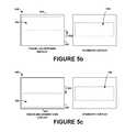
- FIG. 5 bdepicts an example user interface that is appropriate for traveling upstairs
- FIG. 5 cdepicts an example user interface that is appropriate for traveling downstairs. It should be understood that these example user interfaces are illustrative examples, and other example user interfaces appropriate for various user activities are possible as well.
- a standard user interfacemay be a user interface that is appropriate for when a user is standing. For instance, when a user is standing, the user may be capable of processing a standard amount of computer-generated information. When a user is standing, the user may typically be looking forward. Thus, in a standard user interface, the display of the computer-generated information may be confined to a certain portion of the display screen of the wearable computing device such that the computer-generated information is in the user's main line of sight. As an example, FIGS.
- a standard user interfacemay include a display that has an appropriate visual density of computer-generated information.
- the wearable computing device 100may make changes from the standard user interface in accordance with the activity in which the user is engaged. In particular, changes can be made to the standard user interface in order to make the user interface more appropriate for the given user activity.
- User interface 502comprises a display 506 that includes running-related statistics of the user.
- Statistics 504 a - care example running statistics that could be displayed in user interface 502 .
- statistic 504 ashows the time elapsed since the user began running
- statistic 504 bshows the user's pace (e.g., MPH)
- statistic 504 cshows the user's remaining distance.
- the usercould instruct the wearable computing device regarding the distance the user plans to run.
- the wearable computing devicecould have a preset distance goal for when the wearable computing device detects that the user is running (e.g., a preset distance goal of three miles).
- the user interface 502comprises a display 506 with a visual density that is appropriate for running.
- the visual density that is appropriate for runningcomprises a visual density that is less dense that a visual density that is appropriate for walking, sitting, or standing. That is, the computer-generated information shown in display 504 is not as dense as computer-generated information shown in a display that is appropriate for walking, sitting, or standing. For instance, the display appropriate for running may have less computer-generated information shown in the display.
- a less dense visual density for a user that is running as opposed to walking or sittingmay be beneficial for the user of the wearable computing device. For instance, the less dense visual density would likely lead to fewer interruptions and distractions to the user's perception of the visual world. Fewer interruptions and distractions may help to prevent distraction to the user while the user is running, which may limit or prevent injuries to the user as the user is running.
- a user interface that is appropriate for runningmay comprise a visual display that is less dense visually in the main line of sight of the user than in a visual display appropriate for walking, standing, or sitting.
- the running related statistics 504 a - care located in the periphery of the display 506 , which would also be in the periphery of the user's field of vision.
- a usercan concentrate primarily on the physical world as the user is running, and the user's primary field of vision is not interrupted by the computer-generated information.
- a user interface that is suitable for runningmay include an audio user-interface setting that is appropriate for running.
- the settingmay be that the wearable computing device automatically plays music that is correlated with the running pace of the user.
- the user interface 540comprises a display 542 where the display is, compared to a standard display (such as the user interface display 550 ), shifted towards a top 544 of a display screen 546 of the wearable computing device.
- the display 542 of the computer-generated informationwill beneficially be more in line with the user's line of sight, since the user is likely looking up as a user is traveling upstairs.
- the computer-generated informationmay be displayed in the display area 550 , which may be in the user's main line of sight. Areas outside the display area may be in the user's peripheral vision.
- This example user-interfacemay also be appropriate for a user traveling (e.g., walking or running) uphill. Further, this example user-interface may also be appropriate for a user that is elevating in any manner at an angle. For instance, the user may be elevating at an angle between 10 degrees and 80 degrees; however, other angles are possible as well.
- the wearable computing devicemay shift the entire display up a given amount, such as the amount indicated by arrow 552 .
- the wearable computing devicecould shift some of the computer-generated information towards the top 544 of the display screen, so that the computer-generated information is more in line with the user's line of sight.
- a user interface 560that is appropriate for a user traveling downstairs is shown.
- the user interface 560comprises display 542 where the display is, compared to a standard display (such as the user interface display 550 ), shifted towards a bottom 562 of a display screen 546 of the wearable computing device.
- the display 542 of the computer-generated informationwill beneficially be more in line with the user's line of sight, since the user is likely looking down as a user is traveling downstairs.
- This example user-interfacemay also be appropriate for a user traveling (e.g., walking or running) downhill. Further, this example user-interface may also be appropriate for a user that is descending in any manner at an angle. For instance, the user may be descending at an angle between 10 degrees and 80 degrees; however, other angles are possible as well.
- the wearable computing devicemay shift the entire display down a given amount, such as the amount indicated by arrow 564 .
- the wearable computing devicecould shift some of the computer-generated information towards the bottom 562 of the display screen, so that the computer-generated information is more in line with the user's line of sight.
- the wearable computing devicecan adjust the user interface as the user's activity changes.
- the accelerometer systemmay detect a change in the user activity of the user from the determined user activity to a second user activity different from the determined user activity. Responsive to detecting the change in the user activity of the user, the wearable computing device may select a second user interface based on the second user activity such that the second user interface is appropriate for the second user activity. For instance, if the system detects that a user is no longer traveling upstairs, the wearable computing device may adjust the visual display to a standard display. Other examples are possible as well.
- the wearable computing devicemay access a user-interface profile.
- the user-interface profilemay, for example, be stored on the device or accessed remotely.
- This user-interface profilemay include a plurality of user-interface settings for a plurality of user activities, in which each user-interface setting is customized for a specific user activity. Selecting a user interface for the wearable computing device such that the user interface is appropriate for the determined user activity may then include selecting from the user-interface profile at least one user-interface setting that is customized for the determined user activity.
- a user-interface profilecould include information relating to a single user or to a plurality of users.
- the user-interface profilemay include information for all four users.
- FIG. 6depicts an example user-interface profile 600 for wearable computing device, in which the user-interface profile 600 includes profile information for four users.
- a usermay customize the user's settings for each user activity.
- the wearable computing devicemay have default settings for a given user activity.
- user 1 and user 2each have customized user profiles for a variety of user activities.
- user 1is associated with customized walking profile 610 , customized running profile 612 , customized traveling-upstairs profile 614 , and customized traveling-downstairs profile 616 .
- user 2is associated with customized walking profile 620 , customized running profile 622 , customized traveling-upstairs profile 624 , and customized traveling-downstairs profile 626 .
- users 3 and 4are associated with default walking profile 630 , default running profile 632 , default traveling-upstairs profile 634 , and default traveling-downstairs profile 636 .
- the wearable computing devicemay be configured to prevent unauthorized use of the wearable computing device.
- users 1 - 4may be the only authorized users of the wearable computing device.
- the accelerometer systemmay be configured to identify whether a user wearing the wearable computing device is authorized to use the device.
- the wearable computing devicemay store movement data for each authorized user of the device. In order to store movement data for each authorized user, the wearable computing device may perform a user setup. During the user setup, the wearable computing device could request the user to perform various activities for a given period of time (e.g., walk for 30 second, run for 30 seconds, etc.). The wearable computing device could then record the data and store it in a profile for the user. When users other than users 1 - 4 attempt to use the wearable computing device, the wearable computing device could lock out the unauthorized users.
- Each usermay have a specific movement pattern that enables the wearable computing device to identify the particular user wearing the wearable computing device based on the accelerometer data.
- the on-board computing system 118may perform calculations suitable for a pattern-recognition problem, such as a nearest-neighbor-model algorithm or an HMM algorithm. If the user is identified as an authorized user (i.e., user 1 - 4 ), the wearable computing device may allow the user to use the device, and the device may adjust the user interface according to user-interface profile 600 when different user activities are detected. However, if the user is not identified as an authorized user, the device could automatically lock, preventing the unauthorized user from using the device.
- the wearable computing devicemay be configured to detect other user activities.
- the accelerometer systemmay be configured to detect whether a user is driving in a car or traveling on a train.
- the wearable computing devicemay then select a user interface that is appropriate for those user activities. For instance, if the wearable computing device determines that a user is traveling in a car, the computing device could automatically turn on the wearable computing device's blue-tooth capability, so that the wearable computing device could automatically connect to wireless communication devices in the user's car.
- the accelerometermay be configured to detect the location of a user based on the accelerometer data and/or other data.
- the wearable computing devicewould determine a user's location based on dead-reckoning principles. For example, a user may typically travel in the same manner and direction when a user is traveling to work. The accelerometer system may detect this typical movement pattern, and may thus detect when a user is traveling to work. When the user arrives at work, the wearable computing device may select a user customized work user interface. Similarly, the wearable computing device may be able to detect when a user travels home from work, and when the user reaches home, the wearable computing device may change the user interface to a user customized home user interface.
- the usersmay be provided with an opportunity to opt in/out of programs or features that involve such personal information (e.g., information about a user's preferences).
- certain datamay be anonymized in one or more ways before it is stored or used, so that personally identifiable information is removed.
- a user's identitymay be anonymized so that the no personally identifiable information can be determined for the user and so that any identified user preferences or user interactions are generalized (for example, generalized based on user demographics) rather than associated with a particular user.
Landscapes
- Engineering & Computer Science (AREA)
- Theoretical Computer Science (AREA)
- General Engineering & Computer Science (AREA)
- Physics & Mathematics (AREA)
- General Physics & Mathematics (AREA)
- Human Computer Interaction (AREA)
- Computer Hardware Design (AREA)
- Optics & Photonics (AREA)
- User Interface Of Digital Computer (AREA)
Abstract
Description
Unless otherwise indicated herein, the materials described in this section are not prior art to the claims in this application and are not admitted to be prior art by inclusion in this section.
Computing devices such as personal computers, laptop computers, tablet computers, cellular phones, and countless types of Internet-capable devices are increasingly prevalent in numerous aspects of modern life. As computers become more advanced, augmented-reality devices, which blend computer-generated information with the user's perception of the physical world, are expected to become more prevalent.
In one aspect, an example method involves: (i) an accelerometer system determining a user activity of a user wearing a wearable computing device; (ii) based on the user activity determined by the accelerometer system, selecting a user interface for the wearable computing device such that the user interface is appropriate for the determined user activity (iii) wherein, if the user activity comprises traveling upstairs, the selected user interface comprises a display where the display is, compared to a standard display, shifted towards a top of a display screen of the wearable computing device; and (iv) wherein, if the user activity comprises traveling downstairs, the selected user interface comprises a display where the display is, compared to a standard display, shifted towards a bottom of a display screen of the wearable computing device.
In an example embodiment, the determined user activity is selected from the group consisting of sitting, walking, running, traveling upstairs, and traveling downstairs. Further, the user interface may include at least one visual user-interface setting appropriate for the determined user activity and/or at least one audio user-interface setting appropriate for the determined user activity.
In another aspect, a non-transitory computer readable medium having instructions stored thereon that, in response to execution by a processor, cause the processor to perform operations is disclosed. According to an example embodiment, the instructions include: (i) instructions for determining a user activity of a user wearing a wearable computing device; and (ii) instructions for, based on the determined user activity, selecting a user interface for the wearable computing device such that the user interface is appropriate for the determined user activity; wherein, if the user activity comprises traveling upstairs, the selected user interface comprises a display where the display is, compared to a standard display, shifted towards a top of a display screen of the wearable computing device; and wherein, if the user activity comprises traveling downstairs, the selected user interface comprises a display where the display is, compared to a standard display, shifted towards a bottom of a display screen of the wearable computing device.
In yet another aspect, a wearable computing system is disclosed. An example wearable computing system includes: (i) a head-mounted display, wherein the head-mounted display is configured to display computer-generated information in accordance with a user interface and to allow visual perception of the physical world; (ii) an accelerometer system configured to determine a user activity of a user wearing the head-mounted display; and (iii) a controller, wherein the controller is configured to, based on the user activity determined by the accelerometer system, select the user interface for the head-mounted display such that the selected user interface is appropriate for the determined user activity; wherein, if the user activity comprises traveling upstairs, the selected user interface comprises a display where the display is, compared to a standard display, shifted towards a top of a display screen of the head mounted display; and wherein, if the user activity comprises traveling downstairs, the selected user interface comprises a display where the display is, compared to a standard display, shifted towards a bottom of a display screen of the head mounted display.
These as well as other aspects, advantages, and alternatives, will become apparent to those of ordinary skill in the art by reading the following detailed description, with reference where appropriate to the accompanying drawings.
The following detailed description describes various features and functions of the disclosed systems and methods with reference to the accompanying figures. In the figures, similar symbols typically identify similar components, unless context dictates otherwise. The illustrative system and method embodiments described herein are not meant to be limiting. It will be readily understood that certain aspects of the disclosed systems and methods can be arranged and combined in a wide variety of different configurations, all of which are contemplated herein.
A wearable computing device may be configured to display computer-generated information in accordance with a user interface and to allow visual perception of the physical world. Advantageously, the computer-generated information may be integrated with a user's perception of the physical world. For example, the computer-generated information may supplement a user's perception of the physical world with useful computer-generated information related to what the user is perceiving or experiencing at a given moment.
A user may be engaged in a variety of activities while a user is wearing and using a wearable computing device. For instance, the user may be standing, sitting, walking, running, traveling upstairs, or traveling downstairs. A given user interface provided by the wearable computing device may be more appropriate for one type of user activity than another type of user activity. Thus, it may be beneficial for a wearable computing device to adjust the user interface in accordance with the activity of the user wearing the wearable computing device. For instance, the wearable computing device may be configured to provide different user interfaces when a user is standing, sitting, walking, running, traveling upstairs, or traveling downstairs.
The methods and systems described herein can facilitate the selection of a user interface for a wearable computing device such that the user interface is appropriate for the activity in which the user of the wearable computing device is engaged. An example method may involve: (i) an accelerometer system determining a user activity of a user wearing a wearable computing device; and (ii) based on the user activity determined by the accelerometer system, selecting a user interface for the wearable computing device such that the user interface is appropriate for the determined user activity.
In accordance with an example embodiment, the accelerometer system may detect changes in the user activity. Responsive to detecting a change in the activity of the user, the wearable computing device may select a new user interface based on the new user activity such that the new user interface is appropriate for the new user activity. In this way, the user interface of the wearable computing device may adapt to the various activities of the user of the wearable computing device.
The extending side-arms frame elements eyeglasses 102 to the user. The extending side-arms eyeglasses 102 to the user by extending around a rear portion of the user's head. Additionally or alternatively, for example, thesystem 100 may connect to or be affixed within a head-mounted helmet structure. Other possibilities exist as well.
Thesystem 100 may also include an on-board computing system 118, avideo camera 120, asensor 122, and finger-operable touch pads board computing system 118 is shown to be positioned on the extending side-arm 114 of theeyeglasses 102; however, the on-board computing system 118 may be provided on other parts of theeyeglasses 102 or even remote from the glasses (e.g.,computing system 118 could be connected wirelessly or wired to eyeglasses102). The on-board computing system 118 may include a processor and memory, for example. The on-board computing system 118 may be configured to receive and analyze data from thevideo camera 120, the finger-operable touch pads lens elements
Thevideo camera 120 is shown positioned on the extending side-arm 114 of theeyeglasses 102; however, thevideo camera 120 may be provided on other parts of theeyeglasses 102. Thevideo camera 120 may be configured to capture images at various resolutions or at different frame rates. Many video cameras with a small form-factor, such as those used in cell phones or webcams, for example, may be incorporated into an example of thesystem 100. AlthoughFIG. 1 illustrates onevideo camera 120, more video cameras may be used, and each may be configured to capture the same view, or to capture different views. For example, thevideo camera 120 may be forward facing to capture at least a portion of the real-world view perceived by the user. This forward facing image captured by thevideo camera 120 may then be used to generate an augmented reality where computer-generated images appear to interact with the real-world view perceived by the user.
Thesensor 122 is shown mounted on the extending side-arm 116 of theeyeglasses 102; however, thesensor 122 may be provided on other parts of theeyeglasses 102. Thesensor 122 may include one or more of an accelerometer or a gyroscope, for example. Other sensing devices may be included within thesensor 122 or other sensing functions may be performed by thesensor 122.
The finger-operable touch pads arms eyeglasses 102. Each of finger-operable touch pads operable touch pads operable touch pads operable touch pads operable touch pads operable touch pads operable touch pads system 100 may include a microphone configured to receive voice commands from the user. In addition,system 100 may include one or more communication interfaces that allow various types of external user-interface devices to be connected to the wearable computing device. For instance,system 100 may be configured for connectivity with various hand-held keyboards and/or pointing devices.
Thelens elements projectors projectors
In alternative embodiments, other types of display elements may also be used. For example, thelens elements frame elements
Thus, thedevice 138 may include adisplay system 144 comprising aprocessor 146 and adisplay 148. Thedisplay 148 may be, for example, an optical see-through display, an optical see-around display, or a video see-through display. Theprocessor 146 may receive data from theremote device 142, and configure the data for display on thedisplay 148. Theprocessor 146 may be any type of processor, such as a micro-processor or a digital signal processor, for example.
Thedevice 138 may further include on-board data storage, such asmemory 150 coupled to theprocessor 146. Thememory 150 may store software that can be accessed and executed by theprocessor 146, for example.
Theremote device 142 may be any type of computing device or transmitter including a laptop computer, a mobile telephone, etc., that is configured to transmit data to thedevice 138. Theremote device 142 could also be a server or a system of servers. Theremote device 142 and thedevice 138 may contain hardware to enable thecommunication link 140, such as processors, transmitters, receivers, antennas, etc. In another example, theremote device 142 could be a remote accelerometer mounted on the user separate from the head-mounted display of the wearable computing system.
InFIG. 3 , thecommunication link 140 is illustrated as a wireless connection; however, wired connections may also be used. For example, thecommunication link 140 may be a wired link via a serial bus such as a universal serial bus or a parallel bus. A wired connection may be a proprietary connection as well. Thecommunication link 140 may also be a wireless connection using, e.g., Bluetooth® radio technology, communication protocols described in IEEE 802.11 (including any IEEE 802.11 revisions), Cellular technology (such as GSM, CDMA, UMTS, EV-DO, WiMAX, or LTE), or Zigbee® technology, among other possibilities. Theremote device 142 may be accessible via the Internet and may comprise a computing cluster associated with a particular web service (e.g., social-networking, photo sharing, address book, etc.).
Exemplary methods may involve a wearable computing device, such assystem 100, determining what type of user activity a user of the wearable computing device is engaged in, and responsively selecting a user interface for the wearable computing device that is appropriate for the determined user activity.FIG. 4 is a flow chart illustrating a method according to an example embodiment. More specifically,example method 400 involves an accelerometer system determining a user activity of a user wearing a wearable computing device, as shown byblock 402. The wearable computing device then selects, based on the user activity determined by the accelerometer system, a user interface for the wearable computing device such that the user interface is appropriate for the determined user activity, as shown byblock 404. Although theexemplary method 400 is described by way of example as being carried out by thewearable computing device 100, it should be understood that an example method may be carried out by a wearable computing device in combination with one or more other entities, such as a remote accelerometer and/or one or more servers.
A. Determining a User Activity of a User Wearing the Wearable Computing Device
As mentioned above, atblock 402 the accelerometer system may determine a user activity of a user wearing a wearable computing device. With reference toFIG. 1 , the accelerometer system may comprise, for example,sensor 122 and on-board computing system 118. In order to determine the user activity, the accelerometer system may collect acceleration data from theaccelerometer 122. Any suitable accelerometer now known in the art or later developed could be used in the accelerometer system. In an example, a single axis (e.g., up-down axis) accelerometer could be used. However, in another example, a multi-axis accelerometer could be used. In addition, the accelerometer system could include additional movement or motion detection components, such as a gyroscope and/or a compass. Such additional components may provide additional movement or motion data for the accelerometer system to use in order to determine the user activity of the user of the wearable computing device. Other movement-detection devices may be included in the accelerometer system as well.
Based on the accelerometer data, the accelerometer system may determine the activity in which a user of the wearable computing device is engaged. For example, the accelerometer system may determine whether the user is sitting, walking, running, traveling upstairs, and traveling downstairs. It should be understood that determining other types of user activities is possible as well. Each user activity may have a different acceleration pattern associated with the activity. For instance, sitting has a first acceleration pattern, walking has a second acceleration pattern, running has a third acceleration pattern, traveling upstairs has a fourth acceleration pattern, and traveling downstairs has a fifth acceleration pattern. In addition, the acceleration patterns for various activities may be unique to individual users.
The on-board computing system 118 may analyze the data collected byaccelerometer 122 to determine the activity in which the user is engaged. In general, the on-board computing system 118 may determine which activity the collected data most closely matches, and then the on-board computing system 118 may treat the most closely matched activity as the activity in which the user is engaged. In order to determine the most closely matched activity, the on-board computing system 118 may perform calculations suitable for pattern-recognition problems. For instance, the on-board computing system 118 may utilize a nearest-neighbor-model algorithm or a hidden-Markov-model (HMM) algorithm in order to determine the most closely matched activity. Other algorithms are possible as well.
As mentioned above, in the example according toFIG. 1 , the accelerometer system is part of the wearable computing device. However, in another example embodiment, the accelerometer system may be mounted on the user separate from the wearable computing device. For instance, the accelerometer system may be mounted on a user's arm, hip, leg, or foot. In such a case, the accelerometer system could be configured to communicate (e.g., wirelessly) the accelerometer data to the wearable computing device. In another example, different components of the accelerometer system may be located at different locations. For instance, the accelerometer may be located on a user's arm, hip, leg, ankle, or foot, while the computing system of the accelerometer system may be located on the wearable computing device. As another example, the accelerometer system may include a plurality of accelerometers, where each accelerometer is located on a different part of the user's body.
It should be understood that acceleration data may be different for the same activities depending on where the accelerometer system is mounted. Thus, the acceleration patterns associated with a given user activity may differ depending on where the accelerometer is located, and the computing system that analyzes the accelerometer data can take the location of the accelerometer into account when determining the user activity in which the user is engaged.
As a particular example, the acceleration data recorded for various activities will be different for an accelerometer mounted on a user's ankle than for an accelerometer located on the user's head (e.g., an accelerometer in the wearable computing device). For instance, when a user is walking, an accelerometer on a user's ankle would likely move forward and up (and then forward and down) with each step. Further, as a user is taking a step with the other foot, the accelerometer would remain somewhat stationary. However, when a user is walking, an accelerometer on a user's head would generally move forward, while perhaps oscillating up and down slightly with each step of the user. Therefore, the accelerometer data recorded by each of these accelerometers would differ when a user is walking.
As another example, when a user is standing, an accelerometer on a user's ankle would likely remain somewhat stationary, while occasionally shifting location slightly if the user shifts the user's stance. However, when a user is standing, a user may typically sway their head slightly or turn their head, and thus an accelerometer on a user's head may move in accordance with how the user sways or turns their head. As yet another example, when a user is sitting, an accelerometer on a user's ankle may move in accordance with how a user shifts their ankle when sitting (e.g., a user may cross their legs, tap their toes, etc.) However, when a user is sitting, a user may typically sway their head slightly or turn their head, and thus an accelerometer on a user's head may move in accordance with how the user sways or turns their head.
As still yet another example, when a user is traveling upstairs, an accelerometer on a user's ankle would likely move forward and up with each step. Further, as a user is taking a step with the other foot, the accelerometer would remain somewhat stationary. However, an accelerometer on a user's head would generally move both forward and up. As still yet another example, when a user is traveling downstairs, an accelerometer on a user's ankle would likely move forward and down with each step. Further, as a user is taking a step with the other foot, the accelerometer would remain somewhat stationary. However, an accelerometer on a user's head would generally move both forward and down.
It should be understood that above descriptions of these different accelerometer movements for the different user activities are intended as examples only. Each user (and each user's body parts) may move differently depending on the user activity. The accelerometer system may be configured to recognize the movement patterns of each particular user, and to determine the activity each user is engaged in based on the recorded acceleration data.
B. Selecting a User Interface for the Wearable Computing Device Such that the User Interface is Appropriate for the Determined User Activity
As mentioned above, atblock 404, thewearable computing device 100 may select, based on the user activity determined by the accelerometer system, a user interface for the wearable computing device such that the user interface is appropriate for the determined user activity. In an example, a controller of the wearable computing device, such as on-board computing system 118, may make this user-interface selection.
The user interface may include how the user perceives the computer-generated information and/or how the user is able to interact with the wearable computing device. For example, a given user interface may be appropriate for a first activity while being inappropriate (or less appropriate) for a second user activity. For example, the user interface may include visual user-interface settings, and some settings may be appropriate for a given activity but not appropriate (or less appropriate) for another activity. As another example, the user interface may include audio user-interface settings, and some audio settings may be appropriate for a given activity but not appropriate (or less appropriate) for another activity.
Example user interfaces appropriate for different user activities are shown inFIGS. 5 a-c. In particular,FIG. 5 adepicts an example user interface that is appropriate for running,FIG. 5 bdepicts an example user interface that is appropriate for traveling upstairs, andFIG. 5 cdepicts an example user interface that is appropriate for traveling downstairs. It should be understood that these example user interfaces are illustrative examples, and other example user interfaces appropriate for various user activities are possible as well.
In addition, these example user interfaces may differ in various ways from a standard user interface for the wearable computing device. In an example, a standard user interface may be a user interface that is appropriate for when a user is standing. For instance, when a user is standing, the user may be capable of processing a standard amount of computer-generated information. When a user is standing, the user may typically be looking forward. Thus, in a standard user interface, the display of the computer-generated information may be confined to a certain portion of the display screen of the wearable computing device such that the computer-generated information is in the user's main line of sight. As an example,FIGS. 5 band5cdepict a standard user-interface display screen 550 where thedisplay screen 550 is in the user's main line of sight, as opposed to the periphery of the user's sight. In addition, a standard user interface may include a display that has an appropriate visual density of computer-generated information. Thewearable computing device 100 may make changes from the standard user interface in accordance with the activity in which the user is engaged. In particular, changes can be made to the standard user interface in order to make the user interface more appropriate for the given user activity.
With reference toFIG. 5 a, anexample user interface 502 appropriate for running is described.User interface 502 comprises adisplay 506 that includes running-related statistics of the user. Statistics504a-care example running statistics that could be displayed inuser interface 502. In particular, statistic504ashows the time elapsed since the user began running, statistic504bshows the user's pace (e.g., MPH), and statistic504cshows the user's remaining distance. In order to determine the user's remaining distance, the user could instruct the wearable computing device regarding the distance the user plans to run. Alternatively, the wearable computing device could have a preset distance goal for when the wearable computing device detects that the user is running (e.g., a preset distance goal of three miles).
In addition, theuser interface 502 comprises adisplay 506 with a visual density that is appropriate for running. In an example, the visual density that is appropriate for running comprises a visual density that is less dense that a visual density that is appropriate for walking, sitting, or standing. That is, the computer-generated information shown in display504 is not as dense as computer-generated information shown in a display that is appropriate for walking, sitting, or standing. For instance, the display appropriate for running may have less computer-generated information shown in the display.
A less dense visual density for a user that is running as opposed to walking or sitting may be beneficial for the user of the wearable computing device. For instance, the less dense visual density would likely lead to fewer interruptions and distractions to the user's perception of the visual world. Fewer interruptions and distractions may help to prevent distraction to the user while the user is running, which may limit or prevent injuries to the user as the user is running.
In addition, a user interface that is appropriate for running may comprise a visual display that is less dense visually in the main line of sight of the user than in a visual display appropriate for walking, standing, or sitting. For instance, in the example ofFIG. 5 a, the running related statistics504a-care located in the periphery of thedisplay 506, which would also be in the periphery of the user's field of vision. Thus, a user can concentrate primarily on the physical world as the user is running, and the user's primary field of vision is not interrupted by the computer-generated information.
In another example, a user interface that is suitable for running may include an audio user-interface setting that is appropriate for running. For instance, the setting may be that the wearable computing device automatically plays music that is correlated with the running pace of the user.
With reference toFIG. 5 b, auser interface 540 that is appropriate for a user traveling upstairs is shown. In particular, theuser interface 540 comprises adisplay 542 where the display is, compared to a standard display (such as the user interface display550), shifted towards a top544 of adisplay screen 546 of the wearable computing device. As such, thedisplay 542 of the computer-generated information will beneficially be more in line with the user's line of sight, since the user is likely looking up as a user is traveling upstairs. In a standard user interface, the computer-generated information may be displayed in thedisplay area 550, which may be in the user's main line of sight. Areas outside the display area may be in the user's peripheral vision. Beneficially, by shifting the display towards the top of the display screen when a user is traveling upstairs, the computer-generated information remains in the user's main line of sight. This example user-interface may also be appropriate for a user traveling (e.g., walking or running) uphill. Further, this example user-interface may also be appropriate for a user that is elevating in any manner at an angle. For instance, the user may be elevating at an angle between 10 degrees and 80 degrees; however, other angles are possible as well.
In the example ofFIG. 5 b, when an accelerometer system detects that a user is traveling upstairs, the wearable computing device may shift the entire display up a given amount, such as the amount indicated byarrow 552. In an alternative embodiment, the wearable computing device could shift some of the computer-generated information towards the top544 of the display screen, so that the computer-generated information is more in line with the user's line of sight.
With reference toFIG. 5 c, auser interface 560 that is appropriate for a user traveling downstairs is shown. In particular, theuser interface 560 comprisesdisplay 542 where the display is, compared to a standard display (such as the user interface display550), shifted towards abottom 562 of adisplay screen 546 of the wearable computing device. As such, thedisplay 542 of the computer-generated information will beneficially be more in line with the user's line of sight, since the user is likely looking down as a user is traveling downstairs. This example user-interface may also be appropriate for a user traveling (e.g., walking or running) downhill. Further, this example user-interface may also be appropriate for a user that is descending in any manner at an angle. For instance, the user may be descending at an angle between 10 degrees and 80 degrees; however, other angles are possible as well.
Similar to the example ofFIG. 5 b, when an accelerometer system detects that a user is traveling downstairs, the wearable computing device may shift the entire display down a given amount, such as the amount indicated byarrow 564. In an alternative embodiment, the wearable computing device could shift some of the computer-generated information towards thebottom 562 of the display screen, so that the computer-generated information is more in line with the user's line of sight.
As mentioned above, the wearable computing device can adjust the user interface as the user's activity changes. In accordance with an example embodiment, the accelerometer system may detect a change in the user activity of the user from the determined user activity to a second user activity different from the determined user activity. Responsive to detecting the change in the user activity of the user, the wearable computing device may select a second user interface based on the second user activity such that the second user interface is appropriate for the second user activity. For instance, if the system detects that a user is no longer traveling upstairs, the wearable computing device may adjust the visual display to a standard display. Other examples are possible as well.
C. User-Interface Profile
In an example embodiment, the wearable computing device may access a user-interface profile. The user-interface profile may, for example, be stored on the device or accessed remotely. This user-interface profile may include a plurality of user-interface settings for a plurality of user activities, in which each user-interface setting is customized for a specific user activity. Selecting a user interface for the wearable computing device such that the user interface is appropriate for the determined user activity may then include selecting from the user-interface profile at least one user-interface setting that is customized for the determined user activity. A user-interface profile could include information relating to a single user or to a plurality of users. For example, in the case that four users (user1 through user4) are authorized to use the wearable computing device, the user-interface profile may include information for all four users. In this regard,FIG. 6 depicts an example user-interface profile 600 for wearable computing device, in which the user-interface profile 600 includes profile information for four users.
In an example, a user may customize the user's settings for each user activity. In another example, the wearable computing device may have default settings for a given user activity. For instance, inprofile 600, user1 and user2 each have customized user profiles for a variety of user activities. In particular, user1 is associated with customized walkingprofile 610, customized runningprofile 612, customized traveling-upstairs profile 614, and customized traveling-downstairs profile 616. Similarly, user2 is associated with customized walkingprofile 620, customized runningprofile 622, customized traveling-upstairs profile 624, and customized traveling-downstairs profile 626. However, users3 and4 are associated withdefault walking profile 630,default running profile 632, default traveling-upstairs profile 634, and default traveling-downstairs profile 636.
In an example embodiment, the wearable computing device may be configured to prevent unauthorized use of the wearable computing device. For instance, in the example ofFIG. 6 , users1-4 may be the only authorized users of the wearable computing device. The accelerometer system may be configured to identify whether a user wearing the wearable computing device is authorized to use the device. The wearable computing device may store movement data for each authorized user of the device. In order to store movement data for each authorized user, the wearable computing device may perform a user setup. During the user setup, the wearable computing device could request the user to perform various activities for a given period of time (e.g., walk for 30 second, run for 30 seconds, etc.). The wearable computing device could then record the data and store it in a profile for the user. When users other than users1-4 attempt to use the wearable computing device, the wearable computing device could lock out the unauthorized users.
Each user may have a specific movement pattern that enables the wearable computing device to identify the particular user wearing the wearable computing device based on the accelerometer data. In order to determine a particular user wearing the wearable computing device, the on-board computing system 118 may perform calculations suitable for a pattern-recognition problem, such as a nearest-neighbor-model algorithm or an HMM algorithm. If the user is identified as an authorized user (i.e., user1-4), the wearable computing device may allow the user to use the device, and the device may adjust the user interface according to user-interface profile 600 when different user activities are detected. However, if the user is not identified as an authorized user, the device could automatically lock, preventing the unauthorized user from using the device.
In addition to the user activities described above, it should be understood that the wearable computing device may be configured to detect other user activities. For example, the accelerometer system may be configured to detect whether a user is driving in a car or traveling on a train. The wearable computing device may then select a user interface that is appropriate for those user activities. For instance, if the wearable computing device determines that a user is traveling in a car, the computing device could automatically turn on the wearable computing device's blue-tooth capability, so that the wearable computing device could automatically connect to wireless communication devices in the user's car.
As another example, the accelerometer may be configured to detect the location of a user based on the accelerometer data and/or other data. For instance, the wearable computing device would determine a user's location based on dead-reckoning principles. For example, a user may typically travel in the same manner and direction when a user is traveling to work. The accelerometer system may detect this typical movement pattern, and may thus detect when a user is traveling to work. When the user arrives at work, the wearable computing device may select a user customized work user interface. Similarly, the wearable computing device may be able to detect when a user travels home from work, and when the user reaches home, the wearable computing device may change the user interface to a user customized home user interface.
It should be understood that arrangements described herein are for purposes of example only. As such, those skilled in the art will appreciate that other arrangements and other elements (e.g. machines, interfaces, functions, orders, and groupings of functions, etc.) can be used instead, and some elements may be omitted altogether according to the desired results. Further, many of the elements that are described are functional entities that may be implemented as discrete or distributed components or in conjunction with other components, in any suitable combination and location.
It should be understood that for situations in which the systems and methods discussed herein collect and/or use any personal information about users or information that might relate to personal information of users, the users may be provided with an opportunity to opt in/out of programs or features that involve such personal information (e.g., information about a user's preferences). In addition, certain data may be anonymized in one or more ways before it is stored or used, so that personally identifiable information is removed. For example, a user's identity may be anonymized so that the no personally identifiable information can be determined for the user and so that any identified user preferences or user interactions are generalized (for example, generalized based on user demographics) rather than associated with a particular user.
While various aspects and embodiments have been disclosed herein, other aspects and embodiments will be apparent to those skilled in the art. The various aspects and embodiments disclosed herein are for purposes of illustration and are not intended to be limiting, with the true scope and spirit being indicated by the following claims, along with the full scope of equivalents to which such claims are entitled. It is also to be understood that the terminology used herein is for the purpose of describing particular embodiments only, and is not intended to be limiting.
Claims (42)
1. A method comprising:
an accelerometer system determining a user activity of a user wearing a wearable computing device;
based on the user activity determined by the accelerometer system, selecting a user interface for the wearable computing device such that the user interface is appropriate for the determined user activity;
wherein, if the user activity comprises traveling upstairs, the selected user interface comprises a display interface area where the display interface area is, compared to a standard display interface area, shifted towards a top of a display screen of the wearable computing device; and
wherein, if the user activity comprises traveling downstairs, the selected user interface comprises a display interface area where the display interface area is, compared to a standard display interface area, shifted towards a bottom of a display screen of the wearable computing device.
2. The method ofclaim 1 , wherein the determined user activity is selected from the group consisting of standing, sitting, walking, running, traveling upstairs, and traveling downstairs.
3. The method ofclaim 1 , wherein the user interface comprises at least one of a visual user-interface setting appropriate for the determined user activity and an audio user-interface setting appropriate for the determined user activity.
4. The method ofclaim 1 , wherein the user activity comprises running, and wherein the user interface comprises a display of running-related statistics of the user.
5. The method ofclaim 2 , wherein the user activity comprises running, and wherein the user interface comprises a display with a visual density that is appropriate for running.
6. The method ofclaim 5 , wherein the visual density that is appropriate for running comprises a visual density that is less dense that a visual density that is appropriate for walking or sitting.
7. The method ofclaim 1 , further comprising:
the wearable computing device storing a user-interface profile, wherein the user-interface profile comprises a plurality of user-interface settings for a plurality of user activities, in which each user-interface setting is customized for a specific user activity; and
wherein selecting a user interface for the wearable computing device such that the user interface is appropriate for the determined user activity comprises selecting from the user-interface profile at least one user-interface setting that is customized for the determined user activity.
8. The method ofclaim 1 , further comprising:
the accelerometer system detecting a change in the user activity of the user from the determined user activity to a second user activity different from the determined user activity; and
responsive to detecting the change in the user activity of the user, selecting a second user interface based on the second user activity such that the second user interface is appropriate for the second user activity.
9. The method ofclaim 1 , wherein the accelerometer system comprises an accelerometer.
10. The method ofclaim 9 , wherein the accelerometer system further comprises at least one of a gyroscope and compass.
11. The method ofclaim 1 , wherein the accelerometer system is part of the wearable computing device.
12. The method ofclaim 1 , wherein the accelerometer system is mounted on the user separate from the wearable computing device.
13. A non-transitory computer readable medium having instructions stored thereon that, in response to execution by a processor, cause the processor to perform operations, the instructions comprising:
instructions for determining a user activity of a user wearing a wearable computing device;
instructions for, based on the determined user activity, selecting a user interface for the wearable computing device such that the user interface is appropriate for the determined user activity;
wherein, if the user activity comprises traveling upstairs, the selected user interface comprises a display interface area where the display interface area is, compared to a standard display interface area, shifted towards a top of a display screen of the wearable computing device; and
wherein, if the user activity comprises traveling downstairs, the selected user interface comprises a display interface area where the display interface area is, compared to a standard display interface area, shifted towards a bottom of a display screen of the wearable computing device.
14. The non-transitory computer readable medium ofclaim 13 , wherein the instructions further comprise:
instructions for detecting a change in the user activity of the user from the determined user activity to a second user activity; and
instructions for, responsive to detecting the change in the user activity of the user, selecting a second user interface based on the second user activity such that the second user interface is appropriate for the determined second user activity.
15. The non-transitory computer readable medium ofclaim 13 , wherein the determined user activity is selected from the group consisting of sitting, walking, running, traveling upstairs, and traveling downstairs.
16. A wearable computing system comprising:
a head-mounted display, wherein the head-mounted display is configured to display computer-generated information in accordance with a user interface and to allow visual perception of the physical world;
an accelerometer system configured to determine a user activity of a user wearing the head-mounted display; and
a controller, wherein the controller is configured to, based on the user activity determined by the accelerometer system, select the user interface for the head-mounted display such that the selected user interface is appropriate for the determined user activity;
wherein, if the user activity comprises traveling upstairs, the selected user interface comprises a display interface area where the display interface area is, compared to a standard display interface area, shifted towards a top of a display screen of the head mounted display; and
wherein, if the user activity comprises traveling downstairs, the selected user interface comprises a display interface area where the display interface area is, compared to a standard display interface area, shifted towards a bottom of a display screen of the head mounted display.
17. The wearable computing system ofclaim 16 , wherein the determined user activity is selected from the group consisting of sitting, walking, running, traveling upstairs, and traveling downstairs.
18. The wearable computing system ofclaim 16 , wherein the accelerometer system is in the head-mounted display.
19. The wearable computing system ofclaim 16 , wherein the accelerometer system is mounted on the user separate from the head-mounted display.
20. The wearable computing system ofclaim 16 , wherein the accelerometer system comprises at least one of a gyroscope and compass.
21. A method comprising:
an accelerometer system determining a user activity of a user wearing a wearable computing device;
based on the user activity determined by the accelerometer system, selecting a user interface for the wearable computing device such that the user interface is appropriate for the determined user activity;
wherein, if the user activity comprises elevating at an angle, the selected user interface comprises a display interface area where the display interface area is, compared to a standard display interface area, shifted towards a top of a display screen of the wearable computing device; and
wherein, if the user activity comprises descending at an angle, the selected user interface comprises a display interface area where the display interface area is, compared to a standard display interface area, shifted towards a bottom of a display screen of the wearable computing device.
22. The method ofclaim 21 , wherein the determined user activity is selected from the group consisting of standing, sitting, walking, running, traveling upstairs, traveling downstairs, traveling uphill, and traveling downhill.
23. The method ofclaim 21 , wherein the user interface comprises at least one of a visual user-interface setting appropriate for the determined user activity and an audio user-interface setting appropriate for the determined user activity.
24. The method ofclaim 21 , wherein the user activity comprises running, and wherein the user interface comprises a display of running-related statistics of the user.
25. The method ofclaim 22 , wherein the user activity comprises running, and wherein the user interface comprises a display with a visual density that is appropriate for running.
26. The method ofclaim 25 , wherein the visual density that is appropriate for running comprises a visual density that is less dense that a visual density that is appropriate for walking or sitting.
27. The method ofclaim 21 , further comprising:
the wearable computing device storing a user-interface profile, wherein the user-interface profile comprises a plurality of user-interface settings for a plurality of user activities, in which each user-interface setting is customized for a specific user activity; and
wherein selecting a user interface for the wearable computing device such that the user interface is appropriate for the determined user activity comprises selecting from the user-interface profile at least one user-interface setting that is customized for the determined user activity.
28. The method ofclaim 21 , further comprising:
the accelerometer system detecting a change in the user activity of the user from the determined user activity to a second user activity different from the determined user activity; and
responsive to detecting the change in the user activity of the user, selecting a second user interface based on the second user activity such that the second user interface is appropriate for the second user activity.
29. The method ofclaim 21 , wherein the accelerometer system comprises an accelerometer.
30. The method ofclaim 29 , wherein the accelerometer system further comprises at least one of a gyroscope and compass.
31. The method ofclaim 21 , wherein the accelerometer system is part of the wearable computing device.
32. The method ofclaim 21 , wherein the accelerometer system is mounted on the user separate from the wearable computing device.
33. The method ofclaim 21 , wherein elevating at an angle comprises elevating at an angle between 10 and 80 degrees, and wherein descending at an angle comprises descending at an angle between 10 and 80 degrees.
34. A non-transitory computer readable medium having instructions stored thereon that, in response to execution by a processor, cause the processor to perform operations, the instructions comprising:
instructions for determining a user activity of a user wearing a wearable computing device;
instructions for, based on the determined user activity, selecting a user interface for the wearable computing device such that the user interface is appropriate for the determined user activity;
wherein, if the user activity comprises elevating at an angle, the selected user interface comprises a display interface area where the display interface area is, compared to a standard display interface area, shifted towards a top of a display screen of the wearable computing device; and
wherein, if the user activity comprises descending at an angle, the selected user interface comprises a display interface area where the display interface area is, compared to a standard display interface area, shifted towards a bottom of a display screen of the wearable computing device.
35. The non-transitory computer readable medium ofclaim 34 , wherein the instructions further comprise:
instructions for detecting a change in the user activity of the user from the determined user activity to a second user activity; and
instructions for, responsive to detecting the change in the user activity of the user, selecting a second user interface based on the second user activity such that the second user interface is appropriate for the determined second user activity.
36. The non-transitory computer readable medium ofclaim 34 , wherein the determined user activity is selected from the group consisting of sitting, walking, running, traveling upstairs, traveling downstairs, traveling uphill, and traveling downhill.
37. The non-transitory computer readable medium ofclaim 34 , wherein elevating at an angle comprises elevating at an angle between 10 and 80 degrees, and wherein descending at an angle comprises descending at an angle between 10 and 80 degrees.
38. A wearable computing system comprising:
a head-mounted display, wherein the head-mounted display is configured to display computer-generated information in accordance with a user interface and to allow visual perception of the physical world;
an accelerometer system configured to determine a user activity of a user wearing the head-mounted display; and
a controller, wherein the controller is configured to, based on the user activity determined by the accelerometer system, select the user interface for the head-mounted display such that the selected user interface is appropriate for the determined user activity;
wherein, if the user activity comprises elevating at an angle, the selected user interface comprises a display interface area where the display interface area is, compared to a standard display interface area, shifted towards a top of a display screen of the head mounted display; and
wherein, if the user activity comprises descending at an angle, the selected user interface comprises a display interface area where the display interface area is, compared to a standard display interface area, shifted towards a bottom of a display screen of the head mounted display.
39. The wearable computing system ofclaim 38 , wherein the determined user activity is selected from the group consisting of sitting, walking, running, traveling upstairs, traveling downstairs, traveling uphill, and traveling downhill.
40. The wearable computing system ofclaim 38 , wherein the accelerometer system is in the head-mounted display.
41. The wearable computing system ofclaim 38 , wherein the accelerometer system is mounted on the user separate from the head-mounted display.
42. The wearable computing system ofclaim 38 , wherein the accelerometer system comprises at least one of a gyroscope and compass.
Priority Applications (1)
| Application Number | Priority Date | Filing Date | Title |
|---|---|---|---|
| US13/177,152US8184070B1 (en) | 2011-07-06 | 2011-07-06 | Method and system for selecting a user interface for a wearable computing device |
Applications Claiming Priority (1)
| Application Number | Priority Date | Filing Date | Title |
|---|---|---|---|
| US13/177,152US8184070B1 (en) | 2011-07-06 | 2011-07-06 | Method and system for selecting a user interface for a wearable computing device |
Publications (1)
| Publication Number | Publication Date |
|---|---|
| US8184070B1true US8184070B1 (en) | 2012-05-22 |
Family
ID=46061275
Family Applications (1)
| Application Number | Title | Priority Date | Filing Date |
|---|---|---|---|
| US13/177,152ActiveUS8184070B1 (en) | 2011-07-06 | 2011-07-06 | Method and system for selecting a user interface for a wearable computing device |
Country Status (1)
| Country | Link |
|---|---|
| US (1) | US8184070B1 (en) |
Cited By (72)
| Publication number | Priority date | Publication date | Assignee | Title |
|---|---|---|---|---|
| US20110224302A1 (en)* | 2008-11-26 | 2011-09-15 | Merck Patent Gesellschaft Mit Beschrankter Haftung | Difluorophenyldiacylhydrazide derivatives |
| US20120198364A1 (en)* | 2011-01-31 | 2012-08-02 | Sap Ag | User interface style guide compliance reporting |
| US20120194550A1 (en)* | 2010-02-28 | 2012-08-02 | Osterhout Group, Inc. | Sensor-based command and control of external devices with feedback from the external device to the ar glasses |
| US20130044130A1 (en)* | 2011-08-17 | 2013-02-21 | Kevin A. Geisner | Providing contextual personal information by a mixed reality device |
| US8467133B2 (en) | 2010-02-28 | 2013-06-18 | Osterhout Group, Inc. | See-through display with an optical assembly including a wedge-shaped illumination system |
| US8472120B2 (en) | 2010-02-28 | 2013-06-25 | Osterhout Group, Inc. | See-through near-eye display glasses with a small scale image source |
| US8477425B2 (en) | 2010-02-28 | 2013-07-02 | Osterhout Group, Inc. | See-through near-eye display glasses including a partially reflective, partially transmitting optical element |
| US8482859B2 (en) | 2010-02-28 | 2013-07-09 | Osterhout Group, Inc. | See-through near-eye display glasses wherein image light is transmitted to and reflected from an optically flat film |
| US8488246B2 (en) | 2010-02-28 | 2013-07-16 | Osterhout Group, Inc. | See-through near-eye display glasses including a curved polarizing film in the image source, a partially reflective, partially transmitting optical element and an optically flat film |
| US20140078175A1 (en)* | 2012-09-18 | 2014-03-20 | Qualcomm Incorporated | Methods and systems for making the use of head-mounted displays less obvious to non-users |
| US20140143785A1 (en)* | 2012-11-20 | 2014-05-22 | Samsung Electronics Companty, Ltd. | Delegating Processing from Wearable Electronic Device |
| US8814691B2 (en) | 2010-02-28 | 2014-08-26 | Microsoft Corporation | System and method for social networking gaming with an augmented reality |
| US8928695B2 (en) | 2012-10-05 | 2015-01-06 | Elwha Llc | Formatting of one or more persistent augmentations in an augmented view in response to multiple input factors |
| US9013264B2 (en) | 2011-03-12 | 2015-04-21 | Perceptive Devices, Llc | Multipurpose controller for electronic devices, facial expressions management and drowsiness detection |
| US9042596B2 (en) | 2012-06-14 | 2015-05-26 | Medibotics Llc | Willpower watch (TM)—a wearable food consumption monitor |
| US9044543B2 (en) | 2012-07-17 | 2015-06-02 | Elwha Llc | Unmanned device utilization methods and systems |
| US9052845B2 (en) | 2011-01-31 | 2015-06-09 | Sap Se | Unified interface for meta model checking, modifying, and reporting |
| US9061102B2 (en) | 2012-07-17 | 2015-06-23 | Elwha Llc | Unmanned device interaction methods and systems |
| US9077647B2 (en) | 2012-10-05 | 2015-07-07 | Elwha Llc | Correlating user reactions with augmentations displayed through augmented views |
| US9091851B2 (en) | 2010-02-28 | 2015-07-28 | Microsoft Technology Licensing, Llc | Light control in head mounted displays |
| US9097890B2 (en) | 2010-02-28 | 2015-08-04 | Microsoft Technology Licensing, Llc | Grating in a light transmissive illumination system for see-through near-eye display glasses |
| US9097891B2 (en) | 2010-02-28 | 2015-08-04 | Microsoft Technology Licensing, Llc | See-through near-eye display glasses including an auto-brightness control for the display brightness based on the brightness in the environment |
| JP2015523026A (en)* | 2012-06-28 | 2015-08-06 | コピン コーポレーション | Headset computer that can enable and disable functions based on real-time image analysis |
| US9105126B2 (en) | 2012-10-05 | 2015-08-11 | Elwha Llc | Systems and methods for sharing augmentation data |
| US9111384B2 (en) | 2012-10-05 | 2015-08-18 | Elwha Llc | Systems and methods for obtaining and using augmentation data and for sharing usage data |
| US9128281B2 (en) | 2010-09-14 | 2015-09-08 | Microsoft Technology Licensing, Llc | Eyepiece with uniformly illuminated reflective display |
| US9129295B2 (en) | 2010-02-28 | 2015-09-08 | Microsoft Technology Licensing, Llc | See-through near-eye display glasses with a fast response photochromic film system for quick transition from dark to clear |
| US9134534B2 (en) | 2010-02-28 | 2015-09-15 | Microsoft Technology Licensing, Llc | See-through near-eye display glasses including a modular image source |
| US9141188B2 (en) | 2012-10-05 | 2015-09-22 | Elwha Llc | Presenting an augmented view in response to acquisition of data inferring user activity |
| US9182596B2 (en) | 2010-02-28 | 2015-11-10 | Microsoft Technology Licensing, Llc | See-through near-eye display glasses with the optical assembly including absorptive polarizers or anti-reflective coatings to reduce stray light |
| US9213185B1 (en)* | 2012-01-06 | 2015-12-15 | Google Inc. | Display scaling based on movement of a head-mounted display |
| US9213405B2 (en) | 2010-12-16 | 2015-12-15 | Microsoft Technology Licensing, Llc | Comprehension and intent-based content for augmented reality displays |
| US9223134B2 (en) | 2010-02-28 | 2015-12-29 | Microsoft Technology Licensing, Llc | Optical imperfections in a light transmissive illumination system for see-through near-eye display glasses |
| US9229227B2 (en) | 2010-02-28 | 2016-01-05 | Microsoft Technology Licensing, Llc | See-through near-eye display glasses with a light transmissive wedge shaped illumination system |
| US20160004084A1 (en)* | 2013-03-11 | 2016-01-07 | Konica Minolta, Inc. | Wearable Computer |
| US9254099B2 (en) | 2013-05-23 | 2016-02-09 | Medibotics Llc | Smart watch and food-imaging member for monitoring food consumption |
| US9285589B2 (en) | 2010-02-28 | 2016-03-15 | Microsoft Technology Licensing, Llc | AR glasses with event and sensor triggered control of AR eyepiece applications |
| US9298283B1 (en) | 2015-09-10 | 2016-03-29 | Connectivity Labs Inc. | Sedentary virtual reality method and systems |
| US20160124501A1 (en)* | 2014-10-31 | 2016-05-05 | The United States Of America As Represented By The Secretary Of The Navy | Secured mobile maintenance and operator system including wearable augmented reality interface, voice command interface, and visual recognition systems and related methods |
| US9341843B2 (en) | 2010-02-28 | 2016-05-17 | Microsoft Technology Licensing, Llc | See-through near-eye display glasses with a small scale image source |
| US9366862B2 (en) | 2010-02-28 | 2016-06-14 | Microsoft Technology Licensing, Llc | System and method for delivering content to a group of see-through near eye display eyepieces |
| US9442100B2 (en) | 2013-12-18 | 2016-09-13 | Medibotics Llc | Caloric intake measuring system using spectroscopic and 3D imaging analysis |
| US9459846B2 (en) | 2011-01-31 | 2016-10-04 | Sap Se | User interface style guide compliance |
| US9477313B2 (en) | 2012-11-20 | 2016-10-25 | Samsung Electronics Co., Ltd. | User gesture input to wearable electronic device involving outward-facing sensor of device |
| US9514463B2 (en) | 2014-04-11 | 2016-12-06 | Bank Of America Corporation | Determination of customer presence based on communication of a mobile communication device digital signature |
| US9529385B2 (en) | 2013-05-23 | 2016-12-27 | Medibotics Llc | Smart watch and human-to-computer interface for monitoring food consumption |
| US9536449B2 (en) | 2013-05-23 | 2017-01-03 | Medibotics Llc | Smart watch and food utensil for monitoring food consumption |
| US9536350B2 (en) | 2011-08-24 | 2017-01-03 | Microsoft Technology Licensing, Llc | Touch and social cues as inputs into a computer |
| US9582035B2 (en) | 2014-02-25 | 2017-02-28 | Medibotics Llc | Wearable computing devices and methods for the wrist and/or forearm |
| US9588342B2 (en) | 2014-04-11 | 2017-03-07 | Bank Of America Corporation | Customer recognition through use of an optical head-mounted display in a wearable computing device |
| US9671863B2 (en) | 2012-10-05 | 2017-06-06 | Elwha Llc | Correlating user reaction with at least an aspect associated with an augmentation of an augmented view |
| EP3067782A4 (en)* | 2013-11-08 | 2017-07-26 | Sony Corporation | Information processing apparatus, control method, and program |
| US9759917B2 (en) | 2010-02-28 | 2017-09-12 | Microsoft Technology Licensing, Llc | AR glasses with event and sensor triggered AR eyepiece interface to external devices |
| US9858773B2 (en) | 2014-02-19 | 2018-01-02 | Microsoft Technology Licensing, Llc | Wearable computer having a skin-stimulating interface |
| US20180031849A1 (en)* | 2016-07-29 | 2018-02-01 | Panasonic Automotive Systems Company Of America, Division Of Panasonic Corporation Of North America | Augmented reality head-up display road correction |
| US10019962B2 (en) | 2011-08-17 | 2018-07-10 | Microsoft Technology Licensing, Llc | Context adaptive user interface for augmented reality display |
| US10121142B2 (en) | 2014-04-11 | 2018-11-06 | Bank Of America Corporation | User authentication by token and comparison to visitation pattern |
| US10180572B2 (en) | 2010-02-28 | 2019-01-15 | Microsoft Technology Licensing, Llc | AR glasses with event and user action control of external applications |
| US10185416B2 (en) | 2012-11-20 | 2019-01-22 | Samsung Electronics Co., Ltd. | User gesture input to wearable electronic device involving movement of device |
| US10194060B2 (en) | 2012-11-20 | 2019-01-29 | Samsung Electronics Company, Ltd. | Wearable electronic device |
| US10269179B2 (en) | 2012-10-05 | 2019-04-23 | Elwha Llc | Displaying second augmentations that are based on registered first augmentations |
| US10314492B2 (en) | 2013-05-23 | 2019-06-11 | Medibotics Llc | Wearable spectroscopic sensor to measure food consumption based on interaction between light and the human body |
| US10360733B2 (en) | 2017-06-20 | 2019-07-23 | Bank Of America Corporation | System controlled augmented resource facility |
| US10429888B2 (en) | 2014-02-25 | 2019-10-01 | Medibotics Llc | Wearable computer display devices for the forearm, wrist, and/or hand |
| CN110618755A (en)* | 2014-07-01 | 2019-12-27 | 谷歌有限责任公司 | User interface control of wearable device |
| US10539787B2 (en) | 2010-02-28 | 2020-01-21 | Microsoft Technology Licensing, Llc | Head-worn adaptive display |
| US10551928B2 (en) | 2012-11-20 | 2020-02-04 | Samsung Electronics Company, Ltd. | GUI transitions on wearable electronic device |
| US10574662B2 (en) | 2017-06-20 | 2020-02-25 | Bank Of America Corporation | System for authentication of a user based on multi-factor passively acquired data |
| US10691332B2 (en) | 2014-02-28 | 2020-06-23 | Samsung Electronics Company, Ltd. | Text input on an interactive display |
| US10860100B2 (en) | 2010-02-28 | 2020-12-08 | Microsoft Technology Licensing, Llc | AR glasses with predictive control of external device based on event input |
| US11237719B2 (en) | 2012-11-20 | 2022-02-01 | Samsung Electronics Company, Ltd. | Controlling remote electronic device with wearable electronic device |
| US11372536B2 (en) | 2012-11-20 | 2022-06-28 | Samsung Electronics Company, Ltd. | Transition and interaction model for wearable electronic device |
Citations (26)
| Publication number | Priority date | Publication date | Assignee | Title |
|---|---|---|---|---|
| US6127990A (en)* | 1995-11-28 | 2000-10-03 | Vega Vista, Inc. | Wearable display and methods for controlling same |
| US6135951A (en) | 1997-07-30 | 2000-10-24 | Living Systems, Inc. | Portable aerobic fitness monitor for walking and running |
| US6323807B1 (en) | 2000-02-17 | 2001-11-27 | Mitsubishi Electric Research Laboratories, Inc. | Indoor navigation with wearable passive sensors |
| US20020105482A1 (en)* | 2000-05-26 | 2002-08-08 | Lemelson Jerome H. | System and methods for controlling automatic scrolling of information on a display or screen |
| US20030046401A1 (en) | 2000-10-16 | 2003-03-06 | Abbott Kenneth H. | Dynamically determing appropriate computer user interfaces |
| US6611789B1 (en) | 1997-10-02 | 2003-08-26 | Personal Electric Devices, Inc. | Monitoring activity of a user in locomotion on foot |
| US6898550B1 (en) | 1997-10-02 | 2005-05-24 | Fitsense Technology, Inc. | Monitoring activity of a user in locomotion on foot |
| US6955542B2 (en) | 2002-01-23 | 2005-10-18 | Aquatech Fitness Corp. | System for monitoring repetitive movement |
| US20060097986A1 (en)* | 2004-11-10 | 2006-05-11 | Denso Corporation | Image display system |
| US7162392B2 (en) | 1994-11-21 | 2007-01-09 | Phatrat Technology, Inc. | Sport performance systems for measuring athletic performance, and associated methods |
| US7172563B2 (en) | 2000-12-27 | 2007-02-06 | Sony Corporation | Gait detection system, gait detection apparatus, device, and gait detection method |
| US20070300185A1 (en) | 2006-06-27 | 2007-12-27 | Microsoft Corporation | Activity-centric adaptive user interface |
| US20090055739A1 (en) | 2007-08-23 | 2009-02-26 | Microsoft Corporation | Context-aware adaptive user interface |
| US7561966B2 (en) | 2003-12-17 | 2009-07-14 | Denso Corporation | Vehicle information display system |
| US20090241171A1 (en) | 2006-08-30 | 2009-09-24 | Sunwoo John | Wearable computer system and method controlling information/service in wearable computer system |
| US7623987B2 (en) | 1994-11-21 | 2009-11-24 | Nike, Inc. | Shoes and garments employing one or more of accelerometers, wireless transmitters, processors, altimeters, to determine information such as speed to persons wearing the shoes or garments |
| US20090290450A1 (en) | 2001-12-20 | 2009-11-26 | Daniel Rioux | Head-mounted display apparatus for profiling system |
| US20100048256A1 (en) | 2005-09-30 | 2010-02-25 | Brian Huppi | Automated Response To And Sensing Of User Activity In Portable Devices |
| US7685433B2 (en) | 2004-09-13 | 2010-03-23 | Valtion Teknillinen Tutkimuskeskus | Recognition of live object in motion |
| US20100079356A1 (en) | 2008-09-30 | 2010-04-01 | Apple Inc. | Head-mounted display apparatus for retaining a portable electronic device with display |
| US7711961B2 (en) | 2003-08-27 | 2010-05-04 | Sony Corporation | Electronic apparatus and authenticating method |
| US20110001699A1 (en) | 2009-05-08 | 2011-01-06 | Kopin Corporation | Remote control of host application using motion and voice commands |
| WO2011003181A1 (en) | 2009-07-06 | 2011-01-13 | Autonomous Identity Management Systems Inc. - Aims | Gait-based authentication system |
| US7872636B1 (en)* | 2005-11-23 | 2011-01-18 | Marvell International Ltd. | Virtual pointing devices for displays |
| US20110112771A1 (en) | 2009-11-09 | 2011-05-12 | Barry French | Wearable sensor system with gesture recognition for measuring physical performance |
| US20110227820A1 (en) | 2010-02-28 | 2011-09-22 | Osterhout Group, Inc. | Lock virtual keyboard position in an augmented reality eyepiece |
- 2011
- 2011-07-06USUS13/177,152patent/US8184070B1/enactiveActive
Patent Citations (27)
| Publication number | Priority date | Publication date | Assignee | Title |
|---|---|---|---|---|
| US7623987B2 (en) | 1994-11-21 | 2009-11-24 | Nike, Inc. | Shoes and garments employing one or more of accelerometers, wireless transmitters, processors, altimeters, to determine information such as speed to persons wearing the shoes or garments |
| US7162392B2 (en) | 1994-11-21 | 2007-01-09 | Phatrat Technology, Inc. | Sport performance systems for measuring athletic performance, and associated methods |
| US20110022357A1 (en) | 1994-11-21 | 2011-01-27 | Nike, Inc. | Location determining system |
| US6127990A (en)* | 1995-11-28 | 2000-10-03 | Vega Vista, Inc. | Wearable display and methods for controlling same |
| US6135951A (en) | 1997-07-30 | 2000-10-24 | Living Systems, Inc. | Portable aerobic fitness monitor for walking and running |
| US6898550B1 (en) | 1997-10-02 | 2005-05-24 | Fitsense Technology, Inc. | Monitoring activity of a user in locomotion on foot |
| US6611789B1 (en) | 1997-10-02 | 2003-08-26 | Personal Electric Devices, Inc. | Monitoring activity of a user in locomotion on foot |
| US6323807B1 (en) | 2000-02-17 | 2001-11-27 | Mitsubishi Electric Research Laboratories, Inc. | Indoor navigation with wearable passive sensors |
| US20020105482A1 (en)* | 2000-05-26 | 2002-08-08 | Lemelson Jerome H. | System and methods for controlling automatic scrolling of information on a display or screen |
| US20030046401A1 (en) | 2000-10-16 | 2003-03-06 | Abbott Kenneth H. | Dynamically determing appropriate computer user interfaces |
| US7172563B2 (en) | 2000-12-27 | 2007-02-06 | Sony Corporation | Gait detection system, gait detection apparatus, device, and gait detection method |
| US20090290450A1 (en) | 2001-12-20 | 2009-11-26 | Daniel Rioux | Head-mounted display apparatus for profiling system |
| US6955542B2 (en) | 2002-01-23 | 2005-10-18 | Aquatech Fitness Corp. | System for monitoring repetitive movement |
| US7711961B2 (en) | 2003-08-27 | 2010-05-04 | Sony Corporation | Electronic apparatus and authenticating method |
| US7561966B2 (en) | 2003-12-17 | 2009-07-14 | Denso Corporation | Vehicle information display system |
| US7685433B2 (en) | 2004-09-13 | 2010-03-23 | Valtion Teknillinen Tutkimuskeskus | Recognition of live object in motion |
| US20060097986A1 (en)* | 2004-11-10 | 2006-05-11 | Denso Corporation | Image display system |
| US20100048256A1 (en) | 2005-09-30 | 2010-02-25 | Brian Huppi | Automated Response To And Sensing Of User Activity In Portable Devices |
| US7872636B1 (en)* | 2005-11-23 | 2011-01-18 | Marvell International Ltd. | Virtual pointing devices for displays |
| US20070300185A1 (en) | 2006-06-27 | 2007-12-27 | Microsoft Corporation | Activity-centric adaptive user interface |
| US20090241171A1 (en) | 2006-08-30 | 2009-09-24 | Sunwoo John | Wearable computer system and method controlling information/service in wearable computer system |
| US20090055739A1 (en) | 2007-08-23 | 2009-02-26 | Microsoft Corporation | Context-aware adaptive user interface |
| US20100079356A1 (en) | 2008-09-30 | 2010-04-01 | Apple Inc. | Head-mounted display apparatus for retaining a portable electronic device with display |
| US20110001699A1 (en) | 2009-05-08 | 2011-01-06 | Kopin Corporation | Remote control of host application using motion and voice commands |
| WO2011003181A1 (en) | 2009-07-06 | 2011-01-13 | Autonomous Identity Management Systems Inc. - Aims | Gait-based authentication system |
| US20110112771A1 (en) | 2009-11-09 | 2011-05-12 | Barry French | Wearable sensor system with gesture recognition for measuring physical performance |
| US20110227820A1 (en) | 2010-02-28 | 2011-09-22 | Osterhout Group, Inc. | Lock virtual keyboard position in an augmented reality eyepiece |
Non-Patent Citations (3)
| Title |
|---|
| Buttussi et al., MOPET: A context-aware and user-adaptive wearable system for fitness training, Artificial Intelligence in Medicine, vol. 42, Issue 2, Wearable Computing and Artificial Intelligence for Healthcare Applications, Feb. 2008, pp. 153-163. |
| Cakmakci, O., et al., "Head-Word Displays: A Review," Journal of Display Technology, vol. 2, pp. 199-216, 2006. |
| Gafurov et al., "Biometric Gait Authentication Using Accelerometer Sensor", Journal of Computers, vol. 1, No. 7, pp. 51-59, Oct./Nov. 2006. |
Cited By (101)
| Publication number | Priority date | Publication date | Assignee | Title |
|---|---|---|---|---|
| US20110224302A1 (en)* | 2008-11-26 | 2011-09-15 | Merck Patent Gesellschaft Mit Beschrankter Haftung | Difluorophenyldiacylhydrazide derivatives |
| US9229227B2 (en) | 2010-02-28 | 2016-01-05 | Microsoft Technology Licensing, Llc | See-through near-eye display glasses with a light transmissive wedge shaped illumination system |
| US9285589B2 (en) | 2010-02-28 | 2016-03-15 | Microsoft Technology Licensing, Llc | AR glasses with event and sensor triggered control of AR eyepiece applications |
| US9223134B2 (en) | 2010-02-28 | 2015-12-29 | Microsoft Technology Licensing, Llc | Optical imperfections in a light transmissive illumination system for see-through near-eye display glasses |
| US8467133B2 (en) | 2010-02-28 | 2013-06-18 | Osterhout Group, Inc. | See-through display with an optical assembly including a wedge-shaped illumination system |
| US8472120B2 (en) | 2010-02-28 | 2013-06-25 | Osterhout Group, Inc. | See-through near-eye display glasses with a small scale image source |
| US8477425B2 (en) | 2010-02-28 | 2013-07-02 | Osterhout Group, Inc. | See-through near-eye display glasses including a partially reflective, partially transmitting optical element |
| US8482859B2 (en) | 2010-02-28 | 2013-07-09 | Osterhout Group, Inc. | See-through near-eye display glasses wherein image light is transmitted to and reflected from an optically flat film |
| US8488246B2 (en) | 2010-02-28 | 2013-07-16 | Osterhout Group, Inc. | See-through near-eye display glasses including a curved polarizing film in the image source, a partially reflective, partially transmitting optical element and an optically flat film |
| US9759917B2 (en) | 2010-02-28 | 2017-09-12 | Microsoft Technology Licensing, Llc | AR glasses with event and sensor triggered AR eyepiece interface to external devices |
| US9366862B2 (en) | 2010-02-28 | 2016-06-14 | Microsoft Technology Licensing, Llc | System and method for delivering content to a group of see-through near eye display eyepieces |
| US8814691B2 (en) | 2010-02-28 | 2014-08-26 | Microsoft Corporation | System and method for social networking gaming with an augmented reality |
| US10860100B2 (en) | 2010-02-28 | 2020-12-08 | Microsoft Technology Licensing, Llc | AR glasses with predictive control of external device based on event input |
| US10539787B2 (en) | 2010-02-28 | 2020-01-21 | Microsoft Technology Licensing, Llc | Head-worn adaptive display |
| US10180572B2 (en) | 2010-02-28 | 2019-01-15 | Microsoft Technology Licensing, Llc | AR glasses with event and user action control of external applications |
| US9341843B2 (en) | 2010-02-28 | 2016-05-17 | Microsoft Technology Licensing, Llc | See-through near-eye display glasses with a small scale image source |
| US9134534B2 (en) | 2010-02-28 | 2015-09-15 | Microsoft Technology Licensing, Llc | See-through near-eye display glasses including a modular image source |
| US9129295B2 (en) | 2010-02-28 | 2015-09-08 | Microsoft Technology Licensing, Llc | See-through near-eye display glasses with a fast response photochromic film system for quick transition from dark to clear |
| US9329689B2 (en) | 2010-02-28 | 2016-05-03 | Microsoft Technology Licensing, Llc | Method and apparatus for biometric data capture |
| US10268888B2 (en) | 2010-02-28 | 2019-04-23 | Microsoft Technology Licensing, Llc | Method and apparatus for biometric data capture |
| US9091851B2 (en) | 2010-02-28 | 2015-07-28 | Microsoft Technology Licensing, Llc | Light control in head mounted displays |
| US9097890B2 (en) | 2010-02-28 | 2015-08-04 | Microsoft Technology Licensing, Llc | Grating in a light transmissive illumination system for see-through near-eye display glasses |
| US9097891B2 (en) | 2010-02-28 | 2015-08-04 | Microsoft Technology Licensing, Llc | See-through near-eye display glasses including an auto-brightness control for the display brightness based on the brightness in the environment |
| US9182596B2 (en) | 2010-02-28 | 2015-11-10 | Microsoft Technology Licensing, Llc | See-through near-eye display glasses with the optical assembly including absorptive polarizers or anti-reflective coatings to reduce stray light |
| US9875406B2 (en) | 2010-02-28 | 2018-01-23 | Microsoft Technology Licensing, Llc | Adjustable extension for temple arm |
| US20120194550A1 (en)* | 2010-02-28 | 2012-08-02 | Osterhout Group, Inc. | Sensor-based command and control of external devices with feedback from the external device to the ar glasses |
| US9128281B2 (en) | 2010-09-14 | 2015-09-08 | Microsoft Technology Licensing, Llc | Eyepiece with uniformly illuminated reflective display |
| US9213405B2 (en) | 2010-12-16 | 2015-12-15 | Microsoft Technology Licensing, Llc | Comprehension and intent-based content for augmented reality displays |
| US9841956B2 (en)* | 2011-01-31 | 2017-12-12 | Sap Se | User interface style guide compliance reporting |
| US9052845B2 (en) | 2011-01-31 | 2015-06-09 | Sap Se | Unified interface for meta model checking, modifying, and reporting |
| US20120198364A1 (en)* | 2011-01-31 | 2012-08-02 | Sap Ag | User interface style guide compliance reporting |
| US9459846B2 (en) | 2011-01-31 | 2016-10-04 | Sap Se | User interface style guide compliance |
| US9013264B2 (en) | 2011-03-12 | 2015-04-21 | Perceptive Devices, Llc | Multipurpose controller for electronic devices, facial expressions management and drowsiness detection |
| US9153195B2 (en)* | 2011-08-17 | 2015-10-06 | Microsoft Technology Licensing, Llc | Providing contextual personal information by a mixed reality device |
| US20130044130A1 (en)* | 2011-08-17 | 2013-02-21 | Kevin A. Geisner | Providing contextual personal information by a mixed reality device |
| US10019962B2 (en) | 2011-08-17 | 2018-07-10 | Microsoft Technology Licensing, Llc | Context adaptive user interface for augmented reality display |
| US10223832B2 (en) | 2011-08-17 | 2019-03-05 | Microsoft Technology Licensing, Llc | Providing location occupancy analysis via a mixed reality device |
| US9536350B2 (en) | 2011-08-24 | 2017-01-03 | Microsoft Technology Licensing, Llc | Touch and social cues as inputs into a computer |
| US11127210B2 (en) | 2011-08-24 | 2021-09-21 | Microsoft Technology Licensing, Llc | Touch and social cues as inputs into a computer |
| US9213185B1 (en)* | 2012-01-06 | 2015-12-15 | Google Inc. | Display scaling based on movement of a head-mounted display |
| US9042596B2 (en) | 2012-06-14 | 2015-05-26 | Medibotics Llc | Willpower watch (TM)—a wearable food consumption monitor |
| JP2015523026A (en)* | 2012-06-28 | 2015-08-06 | コピン コーポレーション | Headset computer that can enable and disable functions based on real-time image analysis |
| US9061102B2 (en) | 2012-07-17 | 2015-06-23 | Elwha Llc | Unmanned device interaction methods and systems |
| US9044543B2 (en) | 2012-07-17 | 2015-06-02 | Elwha Llc | Unmanned device utilization methods and systems |
| US9798325B2 (en) | 2012-07-17 | 2017-10-24 | Elwha Llc | Unmanned device interaction methods and systems |
| US9254363B2 (en) | 2012-07-17 | 2016-02-09 | Elwha Llc | Unmanned device interaction methods and systems |
| US9733644B2 (en) | 2012-07-17 | 2017-08-15 | Elwha Llc | Unmanned device interaction methods and systems |
| US10019000B2 (en) | 2012-07-17 | 2018-07-10 | Elwha Llc | Unmanned device utilization methods and systems |
| US9713675B2 (en) | 2012-07-17 | 2017-07-25 | Elwha Llc | Unmanned device interaction methods and systems |
| US9310611B2 (en)* | 2012-09-18 | 2016-04-12 | Qualcomm Incorporated | Methods and systems for making the use of head-mounted displays less obvious to non-users |
| US20140078175A1 (en)* | 2012-09-18 | 2014-03-20 | Qualcomm Incorporated | Methods and systems for making the use of head-mounted displays less obvious to non-users |
| US10180715B2 (en) | 2012-10-05 | 2019-01-15 | Elwha Llc | Correlating user reaction with at least an aspect associated with an augmentation of an augmented view |
| US9141188B2 (en) | 2012-10-05 | 2015-09-22 | Elwha Llc | Presenting an augmented view in response to acquisition of data inferring user activity |
| US8928695B2 (en) | 2012-10-05 | 2015-01-06 | Elwha Llc | Formatting of one or more persistent augmentations in an augmented view in response to multiple input factors |
| US10713846B2 (en) | 2012-10-05 | 2020-07-14 | Elwha Llc | Systems and methods for sharing augmentation data |
| US10665017B2 (en) | 2012-10-05 | 2020-05-26 | Elwha Llc | Displaying in response to detecting one or more user behaviors one or more second augmentations that are based on one or more registered first augmentations |
| US8941689B2 (en) | 2012-10-05 | 2015-01-27 | Elwha Llc | Formatting of one or more persistent augmentations in an augmented view in response to multiple input factors |
| US10269179B2 (en) | 2012-10-05 | 2019-04-23 | Elwha Llc | Displaying second augmentations that are based on registered first augmentations |
| US9674047B2 (en) | 2012-10-05 | 2017-06-06 | Elwha Llc | Correlating user reactions with augmentations displayed through augmented views |
| US9671863B2 (en) | 2012-10-05 | 2017-06-06 | Elwha Llc | Correlating user reaction with at least an aspect associated with an augmentation of an augmented view |
| US9077647B2 (en) | 2012-10-05 | 2015-07-07 | Elwha Llc | Correlating user reactions with augmentations displayed through augmented views |
| US10254830B2 (en) | 2012-10-05 | 2019-04-09 | Elwha Llc | Correlating user reaction with at least an aspect associated with an augmentation of an augmented view |
| US9448623B2 (en) | 2012-10-05 | 2016-09-20 | Elwha Llc | Presenting an augmented view in response to acquisition of data inferring user activity |
| US9105126B2 (en) | 2012-10-05 | 2015-08-11 | Elwha Llc | Systems and methods for sharing augmentation data |
| US9111384B2 (en) | 2012-10-05 | 2015-08-18 | Elwha Llc | Systems and methods for obtaining and using augmentation data and for sharing usage data |
| US9111383B2 (en) | 2012-10-05 | 2015-08-18 | Elwha Llc | Systems and methods for obtaining and using augmentation data and for sharing usage data |
| US10185416B2 (en) | 2012-11-20 | 2019-01-22 | Samsung Electronics Co., Ltd. | User gesture input to wearable electronic device involving movement of device |
| US20140143785A1 (en)* | 2012-11-20 | 2014-05-22 | Samsung Electronics Companty, Ltd. | Delegating Processing from Wearable Electronic Device |
| US10423214B2 (en)* | 2012-11-20 | 2019-09-24 | Samsung Electronics Company, Ltd | Delegating processing from wearable electronic device |
| US10551928B2 (en) | 2012-11-20 | 2020-02-04 | Samsung Electronics Company, Ltd. | GUI transitions on wearable electronic device |
| US11372536B2 (en) | 2012-11-20 | 2022-06-28 | Samsung Electronics Company, Ltd. | Transition and interaction model for wearable electronic device |
| US10194060B2 (en) | 2012-11-20 | 2019-01-29 | Samsung Electronics Company, Ltd. | Wearable electronic device |
| US11237719B2 (en) | 2012-11-20 | 2022-02-01 | Samsung Electronics Company, Ltd. | Controlling remote electronic device with wearable electronic device |
| US9477313B2 (en) | 2012-11-20 | 2016-10-25 | Samsung Electronics Co., Ltd. | User gesture input to wearable electronic device involving outward-facing sensor of device |
| US9625725B2 (en)* | 2013-03-11 | 2017-04-18 | Konica Minolta, Inc. | Wearable computer |
| US20160004084A1 (en)* | 2013-03-11 | 2016-01-07 | Konica Minolta, Inc. | Wearable Computer |
| US9536449B2 (en) | 2013-05-23 | 2017-01-03 | Medibotics Llc | Smart watch and food utensil for monitoring food consumption |
| US9529385B2 (en) | 2013-05-23 | 2016-12-27 | Medibotics Llc | Smart watch and human-to-computer interface for monitoring food consumption |
| US9254099B2 (en) | 2013-05-23 | 2016-02-09 | Medibotics Llc | Smart watch and food-imaging member for monitoring food consumption |
| US10314492B2 (en) | 2013-05-23 | 2019-06-11 | Medibotics Llc | Wearable spectroscopic sensor to measure food consumption based on interaction between light and the human body |
| EP3067782A4 (en)* | 2013-11-08 | 2017-07-26 | Sony Corporation | Information processing apparatus, control method, and program |
| US9442100B2 (en) | 2013-12-18 | 2016-09-13 | Medibotics Llc | Caloric intake measuring system using spectroscopic and 3D imaging analysis |
| US9858773B2 (en) | 2014-02-19 | 2018-01-02 | Microsoft Technology Licensing, Llc | Wearable computer having a skin-stimulating interface |
| US9582035B2 (en) | 2014-02-25 | 2017-02-28 | Medibotics Llc | Wearable computing devices and methods for the wrist and/or forearm |
| US10429888B2 (en) | 2014-02-25 | 2019-10-01 | Medibotics Llc | Wearable computer display devices for the forearm, wrist, and/or hand |
| US10691332B2 (en) | 2014-02-28 | 2020-06-23 | Samsung Electronics Company, Ltd. | Text input on an interactive display |
| US9588342B2 (en) | 2014-04-11 | 2017-03-07 | Bank Of America Corporation | Customer recognition through use of an optical head-mounted display in a wearable computing device |
| US9514463B2 (en) | 2014-04-11 | 2016-12-06 | Bank Of America Corporation | Determination of customer presence based on communication of a mobile communication device digital signature |
| US10121142B2 (en) | 2014-04-11 | 2018-11-06 | Bank Of America Corporation | User authentication by token and comparison to visitation pattern |
| CN110618755A (en)* | 2014-07-01 | 2019-12-27 | 谷歌有限责任公司 | User interface control of wearable device |
| US9746913B2 (en)* | 2014-10-31 | 2017-08-29 | The United States Of America As Represented By The Secretary Of The Navy | Secured mobile maintenance and operator system including wearable augmented reality interface, voice command interface, and visual recognition systems and related methods |
| US20160124501A1 (en)* | 2014-10-31 | 2016-05-05 | The United States Of America As Represented By The Secretary Of The Navy | Secured mobile maintenance and operator system including wearable augmented reality interface, voice command interface, and visual recognition systems and related methods |
| US11125996B2 (en) | 2015-09-10 | 2021-09-21 | Connectivity Labs Inc. | Sedentary virtual reality method and systems |
| US10345588B2 (en) | 2015-09-10 | 2019-07-09 | Connectivity Labs Inc. | Sedentary virtual reality method and systems |
| US9298283B1 (en) | 2015-09-10 | 2016-03-29 | Connectivity Labs Inc. | Sedentary virtual reality method and systems |
| US9804394B2 (en) | 2015-09-10 | 2017-10-31 | Connectivity Labs Inc. | Sedentary virtual reality method and systems |
| US11803055B2 (en) | 2015-09-10 | 2023-10-31 | Connectivity Labs Inc. | Sedentary virtual reality method and systems |
| US20180031849A1 (en)* | 2016-07-29 | 2018-02-01 | Panasonic Automotive Systems Company Of America, Division Of Panasonic Corporation Of North America | Augmented reality head-up display road correction |
| US10574662B2 (en) | 2017-06-20 | 2020-02-25 | Bank Of America Corporation | System for authentication of a user based on multi-factor passively acquired data |
| US10360733B2 (en) | 2017-06-20 | 2019-07-23 | Bank Of America Corporation | System controlled augmented resource facility |
| US11171963B2 (en) | 2017-06-20 | 2021-11-09 | Bank Of America Corporation | System for authentication of a user based on multi-factor passively acquired data |
Similar Documents
| Publication | Publication Date | Title |
|---|---|---|
| US8184070B1 (en) | Method and system for selecting a user interface for a wearable computing device | |
| US10665205B2 (en) | Determining correlated movements associated with movements caused by driving a vehicle | |
| US10417992B2 (en) | On-head detection with touch sensing and eye sensing | |
| US10114466B2 (en) | Methods and systems for hands-free browsing in a wearable computing device | |
| US9557152B2 (en) | Use of comparative sensor data to determine orientation of head relative to body | |
| US9213185B1 (en) | Display scaling based on movement of a head-mounted display | |
| US9536354B2 (en) | Object outlining to initiate a visual search | |
| US8799810B1 (en) | Stability region for a user interface | |
| US9285872B1 (en) | Using head gesture and eye position to wake a head mounted device | |
| US9041623B2 (en) | Total field of view classification for head-mounted display | |
| US9094677B1 (en) | Head mounted display device with automated positioning | |
| US9405977B2 (en) | Using visual layers to aid in initiating a visual search | |
| US9710056B2 (en) | Methods and systems for correlating movement of a device with state changes of the device | |
| US20130241805A1 (en) | Using Convergence Angle to Select Among Different UI Elements | |
| US9274599B1 (en) | Input detection | |
| US20130021374A1 (en) | Manipulating And Displaying An Image On A Wearable Computing System | |
| US9128283B1 (en) | Dynamically adjustable frame | |
| US20160041048A1 (en) | Detecting a State of a Wearable Device | |
| US20150009309A1 (en) | Optical Frame for Glasses and the Like with Built-In Camera and Special Actuator Feature | |
| US10437882B2 (en) | Object occlusion to initiate a visual search | |
| US20170115736A1 (en) | Photo-Based Unlock Patterns | |
| US20150193977A1 (en) | Self-Describing Three-Dimensional (3D) Object Recognition and Control Descriptors for Augmented Reality Interfaces | |
| US20170090557A1 (en) | Systems and Devices for Implementing a Side-Mounted Optical Sensor | |
| CN116724548A (en) | Electronic device for displaying content and method of operating the same | |
| KR20180045644A (en) | Head mounted display apparatus and method for controlling thereof |
Legal Events
| Date | Code | Title | Description |
|---|---|---|---|
| AS | Assignment | Owner name:GOOGLE INC., CALIFORNIA Free format text:ASSIGNMENT OF ASSIGNORS INTEREST;ASSIGNOR:TAUBMAN, GABRIEL;REEL/FRAME:026550/0250 Effective date:20110630 | |
| STCF | Information on status: patent grant | Free format text:PATENTED CASE | |
| FPAY | Fee payment | Year of fee payment:4 | |
| AS | Assignment | Owner name:GOOGLE LLC, CALIFORNIA Free format text:CHANGE OF NAME;ASSIGNOR:GOOGLE INC.;REEL/FRAME:044101/0405 Effective date:20170929 | |
| MAFP | Maintenance fee payment | Free format text:PAYMENT OF MAINTENANCE FEE, 8TH YEAR, LARGE ENTITY (ORIGINAL EVENT CODE: M1552); ENTITY STATUS OF PATENT OWNER: LARGE ENTITY Year of fee payment:8 | |
| MAFP | Maintenance fee payment | Free format text:PAYMENT OF MAINTENANCE FEE, 12TH YEAR, LARGE ENTITY (ORIGINAL EVENT CODE: M1553); ENTITY STATUS OF PATENT OWNER: LARGE ENTITY Year of fee payment:12 |