US8182525B2 - Methods and systems for endovascular aneurysm treatment - Google Patents
Methods and systems for endovascular aneurysm treatmentDownload PDFInfo
- Publication number
- US8182525B2 US8182525B2US12/421,297US42129709AUS8182525B2US 8182525 B2US8182525 B2US 8182525B2US 42129709 AUS42129709 AUS 42129709AUS 8182525 B2US8182525 B2US 8182525B2
- Authority
- US
- United States
- Prior art keywords
- filling
- filling structure
- aneurysm
- fluid
- medium
- Prior art date
- Legal status (The legal status is an assumption and is not a legal conclusion. Google has not performed a legal analysis and makes no representation as to the accuracy of the status listed.)
- Expired - Fee Related, expires
Links
- 206010002329AneurysmDiseases0.000titleclaimsabstractdescription73
- 238000000034methodMethods0.000titleclaimsdescription40
- 238000011282treatmentMethods0.000titledescription10
- 210000003090iliac arteryAnatomy0.000claimsabstractdescription27
- 239000012530fluidSubstances0.000claimsdescription46
- 230000017531blood circulationEffects0.000claimsdescription13
- 229920000642polymerPolymers0.000claimsdescription8
- FAPWRFPIFSIZLT-UHFFFAOYSA-MSodium chlorideChemical compound[Na+].[Cl-]FAPWRFPIFSIZLT-UHFFFAOYSA-M0.000claimsdescription5
- 239000011780sodium chlorideSubstances0.000claimsdescription5
- 238000011065in-situ storageMethods0.000claimsdescription4
- 238000012544monitoring processMethods0.000claimsdescription3
- 230000009969flowable effectEffects0.000claims2
- 208000007474aortic aneurysmDiseases0.000abstractdescription24
- 208000002223abdominal aortic aneurysmDiseases0.000abstractdescription23
- 230000007246mechanismEffects0.000abstractdescription2
- 239000000463materialSubstances0.000description36
- 210000000709aortaAnatomy0.000description15
- 210000002254renal arteryAnatomy0.000description13
- 238000007789sealingMethods0.000description9
- 239000010410layerSubstances0.000description8
- 230000008439repair processEffects0.000description7
- 238000004873anchoringMethods0.000description6
- 238000012986modificationMethods0.000description6
- 230000004048modificationEffects0.000description6
- 210000004204blood vesselAnatomy0.000description5
- 239000000835fiberSubstances0.000description5
- 201000008982Thoracic Aortic AneurysmDiseases0.000description4
- 239000006260foamSubstances0.000description4
- 230000007704transitionEffects0.000description4
- 239000013543active substanceSubstances0.000description3
- 239000000853adhesiveSubstances0.000description3
- 230000001070adhesive effectEffects0.000description3
- 210000002376aorta thoracicAnatomy0.000description3
- 239000003814drugSubstances0.000description3
- 229940079593drugDrugs0.000description3
- 238000003384imaging methodMethods0.000description3
- 238000013508migrationMethods0.000description3
- 230000005012migrationEffects0.000description3
- 238000002355open surgical procedureMethods0.000description3
- 230000002787reinforcementEffects0.000description3
- 238000007788rougheningMethods0.000description3
- 239000000126substanceSubstances0.000description3
- 206010061307Neck deformityDiseases0.000description2
- 208000007536ThrombosisDiseases0.000description2
- 230000003187abdominal effectEffects0.000description2
- 210000003484anatomyAnatomy0.000description2
- 239000008280bloodSubstances0.000description2
- 210000004369bloodAnatomy0.000description2
- -1flockingSubstances0.000description2
- 210000004013groinAnatomy0.000description2
- 239000007943implantSubstances0.000description2
- 238000004519manufacturing processMethods0.000description2
- 239000004005microsphereSubstances0.000description2
- 239000005020polyethylene terephthalateSubstances0.000description2
- 229920002635polyurethanePolymers0.000description2
- 239000004814polyurethaneSubstances0.000description2
- 239000002356single layerSubstances0.000description2
- 238000012360testing methodMethods0.000description2
- 230000002792vascularEffects0.000description2
- 102000008186CollagenHuman genes0.000description1
- 108010035532CollagenProteins0.000description1
- 229920004934Dacron®Polymers0.000description1
- 208000002251Dissecting AneurysmDiseases0.000description1
- 208000001750EndoleakDiseases0.000description1
- 239000004593EpoxySubstances0.000description1
- 239000004826Synthetic adhesiveSubstances0.000description1
- 210000000702aorta abdominalAnatomy0.000description1
- 230000001174ascending effectEffects0.000description1
- QVGXLLKOCUKJST-UHFFFAOYSA-Natomic oxygenChemical compound[O]QVGXLLKOCUKJST-UHFFFAOYSA-N0.000description1
- 230000008901benefitEffects0.000description1
- 230000036760body temperatureEffects0.000description1
- 230000015556catabolic processEffects0.000description1
- 230000002490cerebral effectEffects0.000description1
- 239000003795chemical substances by applicationSubstances0.000description1
- 238000000576coating methodMethods0.000description1
- 229920001436collagenPolymers0.000description1
- 238000004891communicationMethods0.000description1
- 238000011960computer-aided designMethods0.000description1
- 238000006731degradation reactionMethods0.000description1
- 125000003700epoxy groupChemical group0.000description1
- 239000004744fabricSubstances0.000description1
- 239000000945fillerSubstances0.000description1
- 208000037834fusiform aneurysmDiseases0.000description1
- 239000000499gelSubstances0.000description1
- 230000005484gravityEffects0.000description1
- 230000002008hemorrhagic effectEffects0.000description1
- 230000001788irregularEffects0.000description1
- 229920000126latexPolymers0.000description1
- 239000004816latexSubstances0.000description1
- 239000007788liquidSubstances0.000description1
- 239000012528membraneSubstances0.000description1
- 239000002184metalSubstances0.000description1
- 238000000465mouldingMethods0.000description1
- 229910052760oxygenInorganic materials0.000description1
- 239000001301oxygenSubstances0.000description1
- 230000000149penetrating effectEffects0.000description1
- 229920000052poly(p-xylylene)Polymers0.000description1
- 229920002401polyacrylamidePolymers0.000description1
- 229920000647polyepoxidePolymers0.000description1
- 229920001223polyethylene glycolPolymers0.000description1
- 229920000139polyethylene terephthalatePolymers0.000description1
- 238000006116polymerization reactionMethods0.000description1
- 229920001296polysiloxanePolymers0.000description1
- 239000004810polytetrafluoroethyleneSubstances0.000description1
- 229920001343polytetrafluoroethylenePolymers0.000description1
- 239000000843powderSubstances0.000description1
- 230000001737promoting effectEffects0.000description1
- 238000011084recoveryMethods0.000description1
- 238000000926separation methodMethods0.000description1
- 239000002002slurrySubstances0.000description1
- 238000001356surgical procedureMethods0.000description1
- 230000002885thrombogenetic effectEffects0.000description1
- 230000008467tissue growthEffects0.000description1
- 238000007740vapor depositionMethods0.000description1
- 210000005166vasculatureAnatomy0.000description1
Images


Classifications
- A—HUMAN NECESSITIES
- A61—MEDICAL OR VETERINARY SCIENCE; HYGIENE
- A61F—FILTERS IMPLANTABLE INTO BLOOD VESSELS; PROSTHESES; DEVICES PROVIDING PATENCY TO, OR PREVENTING COLLAPSING OF, TUBULAR STRUCTURES OF THE BODY, e.g. STENTS; ORTHOPAEDIC, NURSING OR CONTRACEPTIVE DEVICES; FOMENTATION; TREATMENT OR PROTECTION OF EYES OR EARS; BANDAGES, DRESSINGS OR ABSORBENT PADS; FIRST-AID KITS
- A61F2/00—Filters implantable into blood vessels; Prostheses, i.e. artificial substitutes or replacements for parts of the body; Appliances for connecting them with the body; Devices providing patency to, or preventing collapsing of, tubular structures of the body, e.g. stents
- A61F2/02—Prostheses implantable into the body
- A61F2/04—Hollow or tubular parts of organs, e.g. bladders, tracheae, bronchi or bile ducts
- A61F2/06—Blood vessels
- A61F2/07—Stent-grafts
- A61F2002/075—Stent-grafts the stent being loosely attached to the graft material, e.g. by stitching
- A—HUMAN NECESSITIES
- A61—MEDICAL OR VETERINARY SCIENCE; HYGIENE
- A61F—FILTERS IMPLANTABLE INTO BLOOD VESSELS; PROSTHESES; DEVICES PROVIDING PATENCY TO, OR PREVENTING COLLAPSING OF, TUBULAR STRUCTURES OF THE BODY, e.g. STENTS; ORTHOPAEDIC, NURSING OR CONTRACEPTIVE DEVICES; FOMENTATION; TREATMENT OR PROTECTION OF EYES OR EARS; BANDAGES, DRESSINGS OR ABSORBENT PADS; FIRST-AID KITS
- A61F2/00—Filters implantable into blood vessels; Prostheses, i.e. artificial substitutes or replacements for parts of the body; Appliances for connecting them with the body; Devices providing patency to, or preventing collapsing of, tubular structures of the body, e.g. stents
- A61F2/02—Prostheses implantable into the body
- A61F2/04—Hollow or tubular parts of organs, e.g. bladders, tracheae, bronchi or bile ducts
- A61F2/06—Blood vessels
- A61F2/07—Stent-grafts
- A61F2002/077—Stent-grafts having means to fill the space between stent-graft and aneurysm wall, e.g. a sleeve
- A—HUMAN NECESSITIES
- A61—MEDICAL OR VETERINARY SCIENCE; HYGIENE
- A61F—FILTERS IMPLANTABLE INTO BLOOD VESSELS; PROSTHESES; DEVICES PROVIDING PATENCY TO, OR PREVENTING COLLAPSING OF, TUBULAR STRUCTURES OF THE BODY, e.g. STENTS; ORTHOPAEDIC, NURSING OR CONTRACEPTIVE DEVICES; FOMENTATION; TREATMENT OR PROTECTION OF EYES OR EARS; BANDAGES, DRESSINGS OR ABSORBENT PADS; FIRST-AID KITS
- A61F2230/00—Geometry of prostheses classified in groups A61F2/00 - A61F2/26 or A61F2/82 or A61F9/00 or A61F11/00 or subgroups thereof
- A61F2230/0002—Two-dimensional shapes, e.g. cross-sections
- A61F2230/0028—Shapes in the form of latin or greek characters
- A61F2230/0034—D-shaped
- A—HUMAN NECESSITIES
- A61—MEDICAL OR VETERINARY SCIENCE; HYGIENE
- A61F—FILTERS IMPLANTABLE INTO BLOOD VESSELS; PROSTHESES; DEVICES PROVIDING PATENCY TO, OR PREVENTING COLLAPSING OF, TUBULAR STRUCTURES OF THE BODY, e.g. STENTS; ORTHOPAEDIC, NURSING OR CONTRACEPTIVE DEVICES; FOMENTATION; TREATMENT OR PROTECTION OF EYES OR EARS; BANDAGES, DRESSINGS OR ABSORBENT PADS; FIRST-AID KITS
- A61F2250/00—Special features of prostheses classified in groups A61F2/00 - A61F2/26 or A61F2/82 or A61F9/00 or A61F11/00 or subgroups thereof
- A61F2250/0003—Special features of prostheses classified in groups A61F2/00 - A61F2/26 or A61F2/82 or A61F9/00 or A61F11/00 or subgroups thereof having an inflatable pocket filled with fluid, e.g. liquid or gas
Definitions
- the present inventionrelates generally to medical apparatus and methods for treatment. More particularly, the present invention relates to expandable prosthesis and methods for treating abdominal and other aneurysms.
- Aneurysmsare enlargements or “bulges” in blood vessels which are often prone to rupture and which therefore present a serious risk to the patient. Aneurysms may occur in any blood vessel but are of particular concern when they occur in the cerebral vasculature or the patient's aorta.
- the present inventionis particularly concerned with aneurysms occurring in the aorta, particularly those referred to as aortic aneurysms.
- Abdominal aortic aneurysms(AAA's) are classified based on their location within the aorta as well as their shape and complexity.
- Aneurysms which are found below the renal arteriesare referred to as infrarenal abdominal aortic aneurysms.
- Suprarenal abdominal aortic aneurysmsoccur above the renal arteries, while thoracic aortic aneurysms (TAA's) occur in the ascending, transverse, or descending part of the upper aorta.
- Infrarenal aneurysmsare the most common, representing about seventy percent (70%) of all aortic aneurysms. Suprarenal aneurysms are less common, representing about 20% of the aortic aneurysms. Thoracic aortic aneurysms are the least common and often the most difficult to treat. Most or all present endovascular systems are also too large (above 12 F) for percutaneous introduction.
- aneurysmThe most common form of aneurysm is “fusiform,” where the enlargement extends about the entire aortic circumference. Less commonly, the aneurysms may be characterized by a bulge on one side of the blood vessel attached at a narrow neck. Thoracic aortic aneurysms are often dissecting aneurysms caused by hemorrhagic separation in the aortic wall, usually within the medial layer. The most common treatment for each of these types and forms of aneurysm is open surgical repair. Open surgical repair is quite successful in patients who are otherwise reasonably healthy and free from significant co-morbidities. Such open surgical procedures are problematic, however, since access to the abdominal and thoracic aortas is difficult to obtain and because the aorta must be clamped off, placing significant strain on the patient's heart.
- endoluminal graftshave come into widespread use for the treatment of aortic aneurysm in patients who cannot undergo open surgical procedures.
- endoluminal repairsaccess the aneurysm “endoluminally” through either or both iliac arteries in the groin.
- the graftswhich typically have been fabric or membrane tubes supported and attached by various stent structures are then implanted, typically requiring several pieces or modules to be assembled in situ.
- Successful endoluminal procedureshave a much shorter recovery period than open surgical procedures.
- the multiple component systemsrequire additional time for introducing each piece and even more time for assembling the pieces in situ. Such techniques are not only more time consuming, they are also more technically challenging, increasing the risk of failure.
- Current devicesare also unsuitable for treating many geometrically complex aneurysms, particularly infrarenal aneurysms with little space between the renal arteries and the upper end of the aneurysm, referred to as short-neck or no-neck aneurysms.
- Aneurysms having torturous geometriesare also difficult to treat.
- Such improved methods, systems, and treatmentsshould preferably provide implanted prosthesis which result in minimal or no endoleaks, which resist migration, which are relatively easy to deploy, which have a low introduction profile (preferably below 12 F), and which can treat most or all aneurismal configurations, including short-neck and no-neck aneurysms as well as those with highly irregular and asymmetric geometries. At least some of these objectives will be met by the inventions described hereinafter.
- the present inventionprovides methods, systems, and prosthesis for the endoluminal treatment of aneurysms, particularly aortic aneurysms including both abdominal aortic aneurysms (AAA's) and thoracic aortic aneurysms (TAA's).
- the prosthesiscomprise double-walled filling structures which are pre-shaped and otherwise adapted to substantially fill the enlarged volume of an aneurysm, particularly a fusiform aneurysm, leaving a lumen in place for blood flow.
- the double-walled filling structureswill thus usually have a generally toroidal structure with an outer wall, an inner wall, a potential space or volume between the outer and inner walls to be filled with a filling medium, and a generally tubular lumen inside of the inner wall which provides the blood flow lumen after the prosthesis has been deployed.
- the shape of the filling structurewill be preferably adapted to conform to the aneurysm being treated.
- the filling structurecan be shaped for the aneurismal geometry of a particular patient using imaging and computer-aided design and fabrication techniques.
- a family or collection of filling structureswill be developed having different geometries and sizes so that a treating physician may select a specific filling structure to treat a particular patient based on the size and geometry of that patient's aneurysm.
- the outer wall of the filling structurewill conform or be conformable to the inner surface of the aneurysm being treated. While the inner wall of the structure will be aligned with lumens of the blood vessels on either side of the prosthesis after the prosthesis has been deployed.
- the filling structures of the prosthesiswill usually be formed from a non-compliant material, such as parylene, Dacron, PET, PTFE, a compliant material, such as silicone, polyurethane, latex, or combinations thereof.
- a non-compliant materialsuch as parylene, Dacron, PET, PTFE
- a compliant materialsuch as silicone, polyurethane, latex, or combinations thereof.
- the walls of the filling structuresmay consist of a single layer or may comprise multiple layers which are laminated or otherwise formed together. Different layers may comprise different materials, including both compliant and/or non-compliant materials.
- the structure wallsmay also be reinforced in various ways, including braid reinforcement layers, filament reinforcement layers, and the like. In some instances, it would be possible to include self-expanding scaffolds within the filling structures so that the structures could be initially delivered and be allowed to self-expand at the treatment site, thus obviating the need for an expansion delivery catheter as described as the preferred embodiment below.
- Preferred delivery protocolswill utilize delivery catheters having a balloon or other expandable support for carrying the filling structure.
- the balloonswill preferably be substantially or entirely compliant, although non-compliant and combination compliant/non-compliant balloons may also find use.
- the balloon or other mechanical expansion components of the delivery catheterwill initially be disposed within the inner tubular lumen of the filling structure, with the filling structure generally being collapsed into a low width or low profile configuration over the expansion element.
- the delivery cathetermay then be introduced intraluminally, typically into the iliac artery and upwardly to the region within the aorta to be treated.
- the delivery catheterwill also include one or more lumens, tubes, or other components or structures for delivering the filling medium in a fluid form to an internal filling cavity of the filling structure.
- the delivery cathetercan be used to both initially place and locate the filling structure of the prosthesis at the aneurismal site.
- the internal tubular lumen of the structurecan be expanded using the balloon or other expandable element on the delivery catheter.
- the filling structureitself will be filled and expanded by delivering the filling medium via the catheter into the internal volume of the filling structure. Both expansion and filling operations may be performed simultaneously, or can be performed in either order, i.e. the filling structure may be filled first with the delivery catheter balloon being expanded second, or vice versa.
- the filling structure(s) and/or delivery balloonsmay have radiopaque markers to facilitate placement and/or pressure sensors for monitoring filling and inflation pressures during deployment.
- the filling structurewill be filled with a fluid (prior to hardening as described herein below) at a pressure which is lower than that of the expansion force provided by the delivery catheter, typically the filling pressure of the expandable balloon.
- the filling structurewill be filled with filling medium at a pressure from 80 mm of Hg to 1000 mm of Hg, preferably from 200 mm of Hg to 600 mm of Hg, while the delivery balloon is inflated to a pressure in the range from 100 mm of Hg to 5000 mm of Hg, preferably from 400 mm of Hg to 1000 mm of Hg.
- These pressuresare gage pressures, i.e. measured relative to atmospheric pressure.
- the present inventionincludes delivery of a single prosthesis and filling structure to an aneurysm.
- Delivery of a single filling structurewill be particularly suitable for aneurysms which are remote from a vessel bifurcation so that both ends of the filling structure are in communication with only a single blood vessel lumen.
- aneurysms located adjacent a vessel bifurcationsuch as the most common infrarenal abdominal aortic aneurysms, it will often be preferable to utilize two such filling structures introduced in a generally adjacent, parallel fashion within the aneurismal volume.
- each prosthesiswill usually be delivered separately, one through each of the two iliac arteries. After locating the filling structures of the prosthesis within the aneurismal space, they can be filled simultaneously or sequentially to fill and occupy the entire aneurismal volume, leaving a pair of blood flow lumens.
- Suitable filling materialswill be fluid initially to permit delivery through the delivery catheter and will be curable or otherwise hardenable so that, once in place, the filling structure can be given a final shape which will remain after the delivery catheter is removed.
- the fillable materialswill usually be curable polymers which, after curing, will have a fixed shape with a shore hardness typically in the range from 10 durometer to 140 durometer.
- the polymersmay be delivered as liquids, gels, foams, slurries, or the like. In some instances, the polymers may be epoxies or other curable two-part systems. In other instances, the polymer may comprise a single material which when exposed to the vascular environment within the filling structure changes state over time, typically from zero to ten minutes.
- the filling materialafter curing, will have a specific gravity, typically in the range from 0.1 to 5, more typically from 0.8 to 1.2 which is generally the same as blood or thrombus.
- the filling materialmay also include bulking and other agents to modify density, viscosity, mechanical characteristics or the like, including microspheres, fibers, powders, gasses, radiopaque materials, drugs, and the like.
- Exemplary filling materialsinclude polyurethanes, collagen, polyethylene glycols, microspheres, and the like.
- the filling structures of the prosthesiswill require no additional sealing or anchoring means for holding them in place within the aneurysm.
- additional sealing or anchoring mechanismssuch as stents, scaffolds, hooks, barbs, sealing cuffs, and the like.
- sealing cuffs or stentswhich extend proximately of infrarenal prosthesis, it may be desirable to provide openings or ports to allow the anchoring or sealing devices to extend over the renal ostia while penetrating blood flow into the renal arteries.
- the sealing or anchoring deviceswill typically be attached to and/or overlap with the filling structure of the prosthesis and will provide for a smooth transition from the aortic and/or iliac lumens into the tubular lumens provided by the deployed filling structures.
- the filling structuresmay be modified in a variety of other ways within the scope of the present invention.
- the external surfaces of the filling structuresmay be partially or entirely modified to enhance placement within the aneurismal space, typically by promoting tissue ingrowth or mechanically interlocking with the inner surface of the aneurysm.
- Such surface modificationsinclude surface roughening, surface stippling, surface flocking, fibers disposed over the surface, foam layers disposed over the surface, rings, and the like.
- biologically active substancesover all or a portion of the external surface of the filling structure, such as thrombogenic substances, tissue growth promotants, biological adhesives, and the like.
- synthetic adhesivessuch as polyacrylamides, over the surface to enhance adherence.
- Such surface modificationsmay comprise surface roughening, rings, stipples, flocking, foam layers, fibers, adhesives, and the like.
- the purpose of such surface modificationwill usually be to enhance the filling and bonding to the filling material, and to control the minimum wall thickness when the structure is filled particularly after the filling material has been cured.
- methods for treating an aneurysmcomprise positioning at least one double-walled filling structure across the aneurysm.
- crossing the aneurysmsit is meant generally that the filling structure will extend axially from one anatomical location which has been identified by imaging or otherwise as the beginning of the aneurysm to a space-part location (or locations in the case of bifurcated aneurysm) where it has been established that the aneurysm ends.
- the at least one filling structureis filled with a fluid filling medium so that an out wall of the structure conforms to the inside of the aneurysm and an inner wall of the structure forms a generally tubular lumen to provide for blood flow after the filling structure has been deployed.
- the tubular lumenwill preferably be supported, typically by a balloon or mechanically expansible element, while the filling structure is being filled, after the filling structure has been filled, or during both periods. After the filling structure has been filled, the filling material or medium is hardened while the tubular lumen remains supported.
- the supportwill be provided by a balloon which extends proximally and distally of the filling structure where the balloon may slightly “overexpand” in order to assure the desired smooth transition and conformance of the tubular lumen provided by the filling structure with the native vessel lumens.
- the supportAfter hardening, the support will be removed, leaving the filling structure in place. In some instances, however, prior to hardening, it will be desirable to confirm proper placement of the filling structure. This can be done using imaging techniques or otherwise testing for patency and continuity. In some instances, it may be desirable to first fill the filling structure with saline or other non-hardenable substance to make sure that the geometry of the filling structure is appropriate for the patient being treated. After testing, the saline may be removed and replaced with the hardenable filler.
- abdominal aortic aneurysms and other bifurcated aneurysmsare treated by positioning first and second double-walled filling structures within the aneurismal volume.
- the first and second double-walled filling structuresare positioned across the aneurysm, as defined above, extending from the aorta beneath the renal arteries to each of the iliac arteries, respectively.
- the first fluid filling structureis filled with a fluid filling material
- the second filling structureis also filled with a fluid material
- the outer walls of each filling structurewill conform to the inside surface of the aneurysm as well as to each other, thus providing a pair of tubular lumens for blood flow from the aorta to each of the iliac arteries.
- the tubular lumens of each of the first and second filling structuresare supported while they are being filled or after they have been filled. Still further preferably, the tubular lumens will remain supported while the filling material is hardened, thus assuring that the transitions to the tubular lumens to the native vessel lumens remain properly aligned and conformed.
- systems for treating aneurysmscomprise at least one double-walled filling structure and at least one delivery catheter having an expandable support positionable within a tubular lumen of the filling structure.
- the systemswill usually further comprise a suitable hardenable or curable fluid filling medium.
- a system for treating abdominal aortic aneurysmscomprises a first double-walled filling structure and a second double-walled filling structure.
- the first and second filling structuresare adapted to be filled with a hardenable filling medium while they lie adjacent to each other within the aneurysm.
- the systemsfurther comprise first and second delivery catheters which can be utilized for aligning each of the first and second filling structures properly with the right and left iliacs and the infrarenal aorta as they are being deployed, filled, and hardened.
- FIG. 1illustrates a single prosthesis system comprising a filling structure mounted over a delivery catheter.
- FIG. 2is a cross-sectional view of the filling structure of FIG. 1 illustrating various surface modifications and a filling valve.
- FIGS. 3A-3Cillustrate alternative wall structures for the filling structure.
- FIG. 4illustrates the anatomy of an infrarenal abdominal aortic aneurysm.
- FIGS. 5A-5Dillustrate use of the prosthesis system of FIG. 1 for treating the infrarenal abdominal aortic aneurysm.
- FIG. 6illustrates a system in accordance with the principles of the present invention comprising a pair of prosthesis for delivery to an infrarenal abdominal aortic aneurysm, where each prosthesis comprises a filling structure mounted on a delivery catheter.
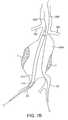
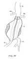
- FIGS. 7A-7Fillustrate use of the prosthesis system of FIG. 6 for treating an infrarenal abdominal aortic aneurysm.
- a system 10 constructed in accordance with the principles of the present invention for delivering a double-walled filling structure 12 to an aneurysmincludes the filling structure and a delivery catheter 14 having an expandable element 16 , typically an inflatable balloon, at its distal end.
- the catheter 14will comprise a guidewire lumen 18 , a balloon inflation lumen (not illustrated) or other structure for expanding other expandable components, and a filling tube 20 for delivering a filling medium or material to an internal space 22 of the double-walled filling structure 12 .
- the internal space 22is defined between an outer wall 24 and inner wall 26 of the filling structure.
- the outer wallUpon inflation with the filling material or medium, the outer wall will expand radially outwardly, as shown in broken line, as will the inner wall 26 , also shown in broken line. Expansion of the inner wall 26 defines an internal lumen 28 .
- the expandable balloon or other structure 16will be expandable to support an inner surface of the lumen 28 , as also in broken line in FIG. 1 .
- the various internal and external surfacesmay be shaped, coated, treated, or otherwise modified, to provide for a number of particular features in accordance with the principles of the present invention.
- the outer wall 24may be shaped to have rings, stipples, or other surface features which are typically formed into the material of the structure at the time of molding, vapor deposition, or other manufacturing process.
- the outer surfacemay also be coated with materials 28 which can be adhesives, drugs, active substances, fibers, flocking, foams, or a variety of other materials. In most cases, such surface features or modifications will be intended to enhance sealing or attachment of the outer wall 24 to the inner surface of the aneurysm being treated.
- the inner surface 30 of the filling volume 22may also be modified by providing features, coatings, surface roughening, or a variety of other modifications.
- the purpose of such internal featuresis typically to enhance adherence of the walls to the filling material or medium as the medium is cured or otherwise hardened.
- materialsmay be coated on all or a portion of the inside surface 30 to induce or catalyze hardening of the filling material as it is being introduced.
- the double-walled filling structure 12will typically comprise at least one valve 40 to permit the introduction of the filling material or medium into the internal volume 22 .
- the valve 40may be a simple flap valve. Other more complex ball valves, and other one-way valve structures may be provided. In other instances, two-way valve structures may be provided to permit both filling and selective emptying of the internal volume 22 .
- the filling tubemay comprise a needle or other filling structure to pass through the valve 40 to permit both filling and removal of filling medium.
- the wall structure of the double-walled filling structuremay be a single layer, typically molded or otherwise conventionally formed.
- the wall structuresmay also be more complex, as illustrated for example, FIGS. 3A-3C .
- FIG. 3Ashows a multi-layered wall comprising layers 42 , 43 and 44 . It will be appreciated that such multiple layer structure can provide for increased strength, puncture resistance, variations in compliance and/or flexibility, differences in resistance to degradation, and the like.
- a single wall or multiple wall structurecan be reinforced by braid, coils, or other metal or non-polymeric reinforcement layers or structures.
- the external surface 24 of the wallmay be covered with drugs, fibers, protrusions, holes, active agents or other substances for a variety of purposes.
- an infrarenal abdominal aortic aneurysmcomprises the thoracic aorta (TA) having renal arteries (RA) at its distal end above the iliac arteries (IA).
- the abdominal aortic aneurysm (AAA)typically forms between the renal arteries (RA) and the iliac arteries (IA) and may have regions of mural thrombus (T) over portions of its inner surface (S).
- the treatment system 10 of FIG. 1may be utilized to treat the complex geometry of the transmural abdominal aortic aneurysm (AAA) of FIG. 4 by first positioning the delivery catheter 14 to place the double-walled filling structure 12 (in its unfilled configuration) generally across the aneurysm from the region of the aorta beneath the renal arteries (RA) to a region over the iliac arteries (IA), as best seen FIG. 5A .
- the delivery catheter 14will be introduced over a guidewire, (GW) through a puncture in the patient's groin accessing the iliac artery by the Seldinger technique.
- GWguidewire
- a hardenable inflation mediumis introduced into the internal space 22 filling of the inner space 22 expands the outer wall 24 of the structure outwardly so that it conforms to the inner surface (S) of the aneurismal space.
- the balloon 16 or other expansible structurewill also be inflated or expanded to open the tubular lumen defined by the interior of the inner wall 26 .
- the balloon 16will be generally non-compliant, typically having a maximum diameter of width which is at or slightly larger than the desired tubular lumen diameter or width through the deployed filling structure 12 .
- the filling structure 12in contrast, will be partially or completely formed from a generally compliant material, thus allowing the non-compliant balloon or other expansible structure 16 to fully open the tubular lumen and conform the ends of the lumens to the aorta and iliac walls, as illustrated in FIG. 5C .
- a lower or proximal end 50 of the tubular lumenwill be flared to a larger diameter so that it can accommodate the openings into both of the iliac arteries (IA) as illustrated.
- IAiliac arteries
- a balloon 16 or other expansible structurewhich will be shaped to preferentially open the lower proximal end 50 of the tubular lumen to a larger diameter than the upper or distal end 52 .
- the fluid filling materialAfter the filling material has been introduced to the filling structure 12 , typically through the filling tube 20 , the fluid filling material must be cured or otherwise hardened to provide for the permanent implant having a generally fixed structure which will remain in place in the particular aneurismal geometry.
- Methods for curing or hardening the filling materialwill depend on the nature of the filling material. For example, certain polymers may be cured by the application of energy, such as heat energy or ultraviolet light. Other polymers may be cured when exposed to body temperature, oxygen, or other conditions which cause polymerization of the fluid filling material. Still others may be mixed immediately prior to use and simply cure after a fixed time, typically minutes. Often, after the filling material has been hardened, the delivery catheter 12 may be removed and the filling structure left in place as the completed prosthetic implant.
- a stent-like structuremay be planted in the upper proximal opening 52 of the tubular lumen of the filling structure 12 in order to help anchor the structure, help prevent intrusion of blood into the region between the outer wall 24 and inner surface (S) of the aneurysm, and to generally improve the transition from the aorta into the tubular lumen.
- the sealing or anchoring structuremay simply comprise a stent-like component, preferably having a port or other access route to allow blood flow into the covered renal arteries (if any).
- the anchor structurecould be another inflatable unit, such as the anchor described in co-pending, commonly owned application Ser. No. 10/668,901 (published as US2004/0116997A1), the full disclosure of which is incorporated herein by reference.
- a pair of double-walled filling structureswill be used to treat infrarenal abdominal aortic aneurysms, instead of only a single filling structure as illustrated in FIGS. 5A-5C .
- a system comprising such a pair of filling structuresis illustrated in FIG. 6 which includes a first filling structure 112 and a second filling structure 212 .
- Each of the filling structures 112 and 212are mounted on delivery catheters 114 and 214 , respectively.
- the components of the filling structures 112 and 212 and delivery catheters 114 and 214are generally the same as those described previously with respect to the single filling structure system 10 of FIG. 1 .
- each of the fillings systems 112 and 212will be given identical numbers with either the 100 base number or 200 base number.
- a principal difference between the filling structures 112 and 212 , on the one hand, and the filling structure 12 of FIG. 1is that the pair of filling structures will generally have asymmetric configurations which are meant to be positioned adjacent to each other within the aneurismal space and to in combination fill that space, as will be described with specific reference to FIG. 7A-7F below.
- a pair of guidewireswill first be introduced, one from each of the iliac arteries (IA). As illustrated in FIG. 7A .
- the first delivery catheter 114will then be positioned over one of the guidewires to position the double-walled filling structure 112 across the aortic aneurysm (AAA), as illustrated in FIG. 7B .
- the second delivery catheter 214is then delivered over the other guidewire (GW) to position the second filling structure 212 adjacent to the first structure 112 within the aneurysm (AAA), as illustrated in FIG. 7C .
- one of the filling structures and associated balloonswill be expanded first, followed by the other of the filling structures and balloon, as illustrated in FIG. 7D where the filling structure 112 and balloon 116 are inflated to fill generally half of the aneurismal volume, as illustrated in FIG. 7D .
- Fillingcan generally be carried out as described above with the one filling structure embodiment, except of course that the filling structure 112 will be expanded to occupy only about one-half of the aneurismal volume.
- the second filling structure 212may be filled, as illustrated in FIG. 7E .
- the upper ends of the balloons 116 and 216will conform the tubular lumens of the filling structures against the walls of the aorta as well as against each other, while the lower ends of the balloons 116 and 216 will conform the tubular lumens into the respective iliac (IA).
- the filling materials or mediumwill be cured or otherwise hardened, and the delivery catheters 114 and 214 removed, respectively.
- the hardened filling structureswill then provide a pair of tubular lumens opening from the aorta beneath the beneath the renal arteries to the right and left iliac arteries, as shown in broken line in FIG. 7 .
- the ability of the filling structures 112 and 212 to conform to the inner surface (S) of the aneurysm, as shown in FIG. 7Fhelps assure that the structures will remain immobilized within the aneurysm with little or no migration.
- Immobilization of the filling structures 112 and 114may be further enhanced by providing any of the surface features described above in connection with the embodiments of FIG. 2 .
- anchoring or sealing structurescould be provided in either of the upper or proximal openings of the tubular lumens into the aorta or from either of the distal or lower openings into the respective iliac arteries.
Landscapes
- Health & Medical Sciences (AREA)
- Heart & Thoracic Surgery (AREA)
- Animal Behavior & Ethology (AREA)
- Cardiology (AREA)
- Oral & Maxillofacial Surgery (AREA)
- Transplantation (AREA)
- Engineering & Computer Science (AREA)
- Biomedical Technology (AREA)
- Gastroenterology & Hepatology (AREA)
- Pulmonology (AREA)
- Vascular Medicine (AREA)
- Life Sciences & Earth Sciences (AREA)
- General Health & Medical Sciences (AREA)
- Public Health (AREA)
- Veterinary Medicine (AREA)
- Prostheses (AREA)
- Surgical Instruments (AREA)
- Materials For Medical Uses (AREA)
- Acyclic And Carbocyclic Compounds In Medicinal Compositions (AREA)
Abstract
Description
Claims (21)
Priority Applications (1)
| Application Number | Priority Date | Filing Date | Title |
|---|---|---|---|
| US12/421,297US8182525B2 (en) | 2004-07-22 | 2009-04-09 | Methods and systems for endovascular aneurysm treatment |
Applications Claiming Priority (3)
| Application Number | Priority Date | Filing Date | Title |
|---|---|---|---|
| US58985004P | 2004-07-22 | 2004-07-22 | |
| US11/187,471US7530988B2 (en) | 2004-07-22 | 2005-07-22 | Methods and systems for endovascular aneurysm treatment |
| US12/421,297US8182525B2 (en) | 2004-07-22 | 2009-04-09 | Methods and systems for endovascular aneurysm treatment |
Related Parent Applications (1)
| Application Number | Title | Priority Date | Filing Date |
|---|---|---|---|
| US11/187,471ContinuationUS7530988B2 (en) | 2004-07-22 | 2005-07-22 | Methods and systems for endovascular aneurysm treatment |
Publications (2)
| Publication Number | Publication Date |
|---|---|
| US20090198267A1 US20090198267A1 (en) | 2009-08-06 |
| US8182525B2true US8182525B2 (en) | 2012-05-22 |
Family
ID=35786748
Family Applications (2)
| Application Number | Title | Priority Date | Filing Date |
|---|---|---|---|
| US11/187,471Active2026-09-08US7530988B2 (en) | 2004-07-22 | 2005-07-22 | Methods and systems for endovascular aneurysm treatment |
| US12/421,297Expired - Fee RelatedUS8182525B2 (en) | 2004-07-22 | 2009-04-09 | Methods and systems for endovascular aneurysm treatment |
Family Applications Before (1)
| Application Number | Title | Priority Date | Filing Date |
|---|---|---|---|
| US11/187,471Active2026-09-08US7530988B2 (en) | 2004-07-22 | 2005-07-22 | Methods and systems for endovascular aneurysm treatment |
Country Status (5)
| Country | Link |
|---|---|
| US (2) | US7530988B2 (en) |
| EP (2) | EP1778131B1 (en) |
| JP (1) | JP4891240B2 (en) |
| AT (1) | ATE540640T1 (en) |
| WO (1) | WO2006012567A2 (en) |
Cited By (8)
| Publication number | Priority date | Publication date | Assignee | Title |
|---|---|---|---|---|
| US9168162B2 (en) | 2011-11-17 | 2015-10-27 | Elgco, Llc | Methods and apparatus for treating a type 2 endoleak from within an endoluminal stent |
| US9289536B2 (en) | 2013-03-14 | 2016-03-22 | Endologix, Inc. | Method for forming materials in situ within a medical device |
| US9730700B2 (en) | 2008-04-25 | 2017-08-15 | Nellix, Inc. | Stent graft delivery system |
| US9737425B2 (en) | 2005-07-07 | 2017-08-22 | Nellix, Inc. | System and methods for endovascular aneurysm treatment |
| US9814612B2 (en) | 2002-09-20 | 2017-11-14 | Nellix, Inc. | Stent-graft with positioning anchor |
| US10022249B2 (en) | 2004-07-22 | 2018-07-17 | Nellix, Inc. | Graft systems having filling structures supported by scaffolds and methods for their use |
| US10058330B2 (en) | 2011-05-11 | 2018-08-28 | Microvention, Inc. | Device for occluding a lumen |
| US10349946B2 (en) | 2011-04-06 | 2019-07-16 | Endologix, Inc. | Method and system for treating aneurysms |
Families Citing this family (58)
| Publication number | Priority date | Publication date | Assignee | Title |
|---|---|---|---|---|
| GB0114918D0 (en)* | 2001-06-19 | 2001-08-08 | Vortex Innovation Ltd | Devices for repairing aneurysms |
| US20060292206A1 (en)* | 2001-11-26 | 2006-12-28 | Kim Steven W | Devices and methods for treatment of vascular aneurysms |
| US7481821B2 (en) | 2002-11-12 | 2009-01-27 | Thomas J. Fogarty | Embolization device and a method of using the same |
| US20040260382A1 (en) | 2003-02-12 | 2004-12-23 | Fogarty Thomas J. | Intravascular implants and methods of using the same |
| US20050015110A1 (en) | 2003-07-18 | 2005-01-20 | Fogarty Thomas J. | Embolization device and a method of using the same |
| ATE540640T1 (en) | 2004-07-22 | 2012-01-15 | Nellix Inc | SYSTEMS FOR THE TREATMENT OF ENDOVASCULAR ANEURYSMS |
| WO2006047747A2 (en)* | 2004-10-26 | 2006-05-04 | University Of Rochester Medical Center | Devices and methods for aneurysm treatment |
| US20060222596A1 (en) | 2005-04-01 | 2006-10-05 | Trivascular, Inc. | Non-degradable, low swelling, water soluble radiopaque hydrogel polymer |
| CA2599460A1 (en) | 2005-04-28 | 2006-11-02 | Nellix, Inc. | Graft systems having filling structures supported by scaffolds and methods for their use |
| US20070150041A1 (en)* | 2005-12-22 | 2007-06-28 | Nellix, Inc. | Methods and systems for aneurysm treatment using filling structures |
| GB0603685D0 (en)* | 2006-02-23 | 2006-04-05 | Angiomed Ag | Vascular prosthesis for aneurysms, set of vascular prostheses, method for manufacturing a vascular prosthesis and method for inserting a vascular prosthesis |
| US20070225799A1 (en)* | 2006-03-24 | 2007-09-27 | Medtronic Vascular, Inc. | Stent, intraluminal stent delivery system, and method of treating a vascular condition |
| US7790273B2 (en)* | 2006-05-24 | 2010-09-07 | Nellix, Inc. | Material for creating multi-layered films and methods for making the same |
| US7872068B2 (en)* | 2006-05-30 | 2011-01-18 | Incept Llc | Materials formable in situ within a medical device |
| US8216297B2 (en)* | 2006-08-14 | 2012-07-10 | Trivascular, Inc. | Dual chamber cuff structure |
| US20080188923A1 (en)* | 2007-02-01 | 2008-08-07 | Jack Fa-De Chu | Endovascular devices to protect aneurysmal wall |
| US20080228259A1 (en)* | 2007-03-16 | 2008-09-18 | Jack Fa-De Chu | Endovascular devices and methods to protect aneurysmal wall |
| US8663309B2 (en) | 2007-09-26 | 2014-03-04 | Trivascular, Inc. | Asymmetric stent apparatus and method |
| US8066755B2 (en) | 2007-09-26 | 2011-11-29 | Trivascular, Inc. | System and method of pivoted stent deployment |
| US8226701B2 (en) | 2007-09-26 | 2012-07-24 | Trivascular, Inc. | Stent and delivery system for deployment thereof |
| US10159557B2 (en) | 2007-10-04 | 2018-12-25 | Trivascular, Inc. | Modular vascular graft for low profile percutaneous delivery |
| US8328861B2 (en) | 2007-11-16 | 2012-12-11 | Trivascular, Inc. | Delivery system and method for bifurcated graft |
| US8083789B2 (en) | 2007-11-16 | 2011-12-27 | Trivascular, Inc. | Securement assembly and method for expandable endovascular device |
| US7862538B2 (en)* | 2008-02-04 | 2011-01-04 | Incept Llc | Surgical delivery system for medical sealant |
| EP2242454A1 (en)* | 2008-02-13 | 2010-10-27 | Nellix, Inc. | Graft endoframe having axially variable characteristics |
| EP2299931B1 (en) | 2008-06-04 | 2020-01-08 | Endologix, Inc. | Sealing apparatus |
| CA2726452A1 (en)* | 2008-06-04 | 2009-12-30 | Nellix, Inc. | Docking apparatus and methods of use |
| US20100016833A1 (en)* | 2008-07-15 | 2010-01-21 | Ogle Matthew F | Devices for the Treatment of Vascular Aneurysm |
| EP2348966A4 (en)* | 2008-10-24 | 2012-08-08 | Innerspace Inc | Catheter with pressure sensor |
| US9427304B2 (en)* | 2008-10-27 | 2016-08-30 | St. Jude Medical, Cardiology Division, Inc. | Multi-layer device with gap for treating a target site and associated method |
| JP2012525239A (en) | 2009-05-01 | 2012-10-22 | エンドロジックス、インク | Transcutaneous methods and devices for treating dissociation (priority information and incorporation by reference) |
| US10772717B2 (en) | 2009-05-01 | 2020-09-15 | Endologix, Inc. | Percutaneous method and device to treat dissections |
| WO2011017123A2 (en) | 2009-07-27 | 2011-02-10 | Endologix, Inc. | Stent graft |
| US8444624B2 (en)* | 2009-10-19 | 2013-05-21 | Vatrix Medical, Inc. | Vascular medical devices with sealing elements and procedures for the treatment of isolated vessel sections |
| EP2506799A4 (en)* | 2009-12-01 | 2014-10-29 | Altura Medical Inc | Modular endograft devices and associated systems and methods |
| US20110276078A1 (en)* | 2009-12-30 | 2011-11-10 | Nellix, Inc. | Filling structure for a graft system and methods of use |
| US8425548B2 (en) | 2010-07-01 | 2013-04-23 | Aneaclose LLC | Occluding member expansion and then stent expansion for aneurysm treatment |
| US8961501B2 (en) | 2010-09-17 | 2015-02-24 | Incept, Llc | Method for applying flowable hydrogels to a cornea |
| US9393100B2 (en)* | 2010-11-17 | 2016-07-19 | Endologix, Inc. | Devices and methods to treat vascular dissections |
| WO2012100059A1 (en)* | 2011-01-19 | 2012-07-26 | Endologix, Inc. | Methods and systems for treating aneurysms |
| US8801768B2 (en) | 2011-01-21 | 2014-08-12 | Endologix, Inc. | Graft systems having semi-permeable filling structures and methods for their use |
| US8978448B2 (en) | 2011-10-11 | 2015-03-17 | Trivascular, Inc. | In vitro testing of endovascular device |
| US8992595B2 (en) | 2012-04-04 | 2015-03-31 | Trivascular, Inc. | Durable stent graft with tapered struts and stable delivery methods and devices |
| US9498363B2 (en) | 2012-04-06 | 2016-11-22 | Trivascular, Inc. | Delivery catheter for endovascular device |
| CA2881535A1 (en) | 2012-08-10 | 2014-02-13 | Altura Medical, Inc. | Stent delivery systems and associated methods |
| US20140180326A1 (en)* | 2012-12-20 | 2014-06-26 | Empire Technology Development Llc | Inflatable balloon for protecting blood vessel |
| US20140194973A1 (en) | 2013-01-10 | 2014-07-10 | Trivascular, Inc. | Sac liner for aneurysm repair |
| WO2014144809A1 (en) | 2013-03-15 | 2014-09-18 | Altura Medical, Inc. | Endograft device delivery systems and associated methods |
| CN106456315B (en) | 2014-03-07 | 2021-06-25 | 恩朵罗杰克斯有限责任公司 | Forming hydrogels and materials for forming hydrogels |
| US10849774B2 (en) | 2014-10-23 | 2020-12-01 | Trivascular, Inc. | Stent graft delivery system with access conduit |
| US10575975B2 (en) | 2015-04-22 | 2020-03-03 | Aneumed, Inc. | Personalized prosthesis and methods of deployment |
| EP3377128A1 (en) | 2015-11-18 | 2018-09-26 | Car Holding B.V. | Curable silicone (pre-)polymer composition comprising a contrast agent |
| WO2017197313A1 (en)* | 2016-05-13 | 2017-11-16 | Endologix, Inc. | Systems and methods with graft body, inflatable fill channel, and filling structure |
| US20180071076A1 (en)* | 2016-09-13 | 2018-03-15 | Lifetech Scientific (Shenzhen) Co., Ltd. | Aneurysm Treatment Method |
| JP6946454B2 (en) | 2017-12-21 | 2021-10-06 | ザ テキサス エーアンドエム ユニバーシティ システムThe Texas A&M University System | Vascular prosthesis to prevent leaks during intravascular aneurysm repair |
| GB2577052B (en) | 2018-09-11 | 2021-04-28 | Strait Access Tech Holdings Pty Ltd | Expandable sleeved stent and method of making such stent |
| FI3941392T3 (en) | 2019-03-20 | 2025-07-28 | Inqb8 Medical Tech Llc | Aortic dissection implant |
| US12246498B2 (en)* | 2021-06-26 | 2025-03-11 | Gabor Matos | Patient specific system and method to repair aortic aneurysms |
Citations (79)
| Publication number | Priority date | Publication date | Assignee | Title |
|---|---|---|---|---|
| US4641653A (en) | 1978-06-02 | 1987-02-10 | Rockey Arthur G | Medical sleeve |
| US4728328A (en) | 1984-10-19 | 1988-03-01 | Research Corporation | Cuffed tubular organic prostheses |
| US5222970A (en)* | 1991-09-06 | 1993-06-29 | William A. Cook Australia Pty. Ltd. | Method of and system for mounting a vascular occlusion balloon on a delivery catheter |
| US5330528A (en) | 1989-12-01 | 1994-07-19 | British Technology Group Limited | Vascular surgical devices |
| US5530528A (en) | 1992-09-28 | 1996-06-25 | Fujitsu Limited | Image forming apparatus having contact type, one-component developing unit |
| US5534024A (en) | 1994-11-04 | 1996-07-09 | Aeroquip Corporation | Intraluminal stenting graft |
| US5665117A (en)* | 1995-11-27 | 1997-09-09 | Rhodes; Valentine J. | Endovascular prosthesis with improved sealing means for aneurysmal arterial disease and method of use |
| US5693088A (en) | 1993-11-08 | 1997-12-02 | Lazarus; Harrison M. | Intraluminal vascular graft |
| US5769882A (en) | 1995-09-08 | 1998-06-23 | Medtronic, Inc. | Methods and apparatus for conformably sealing prostheses within body lumens |
| US5785679A (en) | 1995-07-19 | 1998-07-28 | Endotex Interventional Systems, Inc. | Methods and apparatus for treating aneurysms and arterio-venous fistulas |
| US5824037A (en) | 1995-10-03 | 1998-10-20 | Medtronic, Inc. | Modular intraluminal prostheses construction and methods |
| US5843160A (en) | 1996-04-01 | 1998-12-01 | Rhodes; Valentine J. | Prostheses for aneurysmal and/or occlusive disease at a bifurcation in a vessel, duct, or lumen |
| US5846261A (en) | 1994-07-08 | 1998-12-08 | Aga Medical Corp. | Percutaneous catheter directed occlusion devices |
| US5876448A (en) | 1992-05-08 | 1999-03-02 | Schneider (Usa) Inc. | Esophageal stent |
| US5931866A (en) | 1998-02-24 | 1999-08-03 | Frantzen; John J. | Radially expandable stent featuring accordion stops |
| US5994750A (en) | 1994-11-07 | 1999-11-30 | Canon Kabushiki Kaisha | Microstructure and method of forming the same |
| US6022359A (en) | 1999-01-13 | 2000-02-08 | Frantzen; John J. | Stent delivery system featuring a flexible balloon |
| US6083259A (en) | 1998-11-16 | 2000-07-04 | Frantzen; John J. | Axially non-contracting flexible radially expandable stent |
| US6110198A (en) | 1995-10-03 | 2000-08-29 | Medtronic Inc. | Method for deploying cuff prostheses |
| WO2000051522A1 (en) | 1999-03-03 | 2000-09-08 | Clifford Rowan Murch | Inflatable intraluminal graft |
| US6123715A (en) | 1994-07-08 | 2000-09-26 | Amplatz; Curtis | Method of forming medical devices; intravascular occlusion devices |
| US6168592B1 (en) | 1996-07-26 | 2001-01-02 | Target Therapeutics, Inc. | Aneurysm closure device assembly |
| US6187034B1 (en) | 1999-01-13 | 2001-02-13 | John J. Frantzen | Segmented stent for flexible stent delivery system |
| US6190402B1 (en) | 1996-06-21 | 2001-02-20 | Musc Foundation For Research Development | Insitu formable and self-forming intravascular flow modifier (IFM) and IFM assembly for deployment of same |
| US6196230B1 (en) | 1998-09-10 | 2001-03-06 | Percardia, Inc. | Stent delivery system and method of use |
| WO2001021108A1 (en) | 1999-09-23 | 2001-03-29 | Edwards Lifesciences Corporation | Implants for the use in the treatment of aneurysms |
| US6235050B1 (en) | 1994-05-12 | 2001-05-22 | Endovascular Technologies, Inc. | System and method for intraluminally deploying a bifurcated graft |
| US6261305B1 (en) | 1998-02-12 | 2001-07-17 | Eclips Systems Inc. | Endovascular prothesis with expandable leaf portion |
| US6283991B1 (en) | 1995-12-01 | 2001-09-04 | Medtronics Inc. | Endoluminal prostheses and therapies for highly variable body lumens |
| WO2001066038A2 (en) | 2000-03-03 | 2001-09-13 | Cook Incorporated | Endovascular device having a stent |
| US6296603B1 (en) | 1998-05-26 | 2001-10-02 | Isostent, Inc. | Radioactive intraluminal endovascular prosthesis and method for the treatment of aneurysms |
| US6299597B1 (en) | 1993-09-16 | 2001-10-09 | Scimed Life Systems, Inc. | Percutaneous repair of cardiovascular anomalies and repair compositions |
| US6312463B1 (en) | 2000-02-01 | 2001-11-06 | Endotex Interventional Systems, Inc. | Micro-porous mesh stent with hybrid structure |
| US6312462B1 (en) | 1999-09-22 | 2001-11-06 | Impra, Inc. | Prosthesis for abdominal aortic aneurysm repair |
| US6331184B1 (en) | 1999-12-10 | 2001-12-18 | Scimed Life Systems, Inc. | Detachable covering for an implantable medical device |
| US6334869B1 (en) | 1995-10-30 | 2002-01-01 | World Medical Manufacturing Corporation | Endoluminal prosthesis |
| US20020026217A1 (en) | 2000-04-26 | 2002-02-28 | Steven Baker | Apparatus and method for repair of perigraft flow |
| US6375675B2 (en) | 1998-09-30 | 2002-04-23 | Edwards Lifesciences Corp. | Methods and apparatus for intraluminal placement of a bifurcated intraluminal graft |
| US6409757B1 (en) | 1999-09-15 | 2002-06-25 | Eva Corporation | Method and apparatus for supporting a graft assembly |
| US6463317B1 (en)* | 1998-05-19 | 2002-10-08 | Regents Of The University Of Minnesota | Device and method for the endovascular treatment of aneurysms |
| WO2002102282A1 (en) | 2001-06-19 | 2002-12-27 | Vortex Innovation Limited | Devices for repairing aneurysms |
| US6506204B2 (en) | 1996-01-24 | 2003-01-14 | Aga Medical Corporation | Method and apparatus for occluding aneurysms |
| US20030014075A1 (en) | 2001-07-16 | 2003-01-16 | Microvention, Inc. | Methods, materials and apparatus for deterring or preventing endoleaks following endovascular graft implanation |
| US20030051735A1 (en) | 2001-07-26 | 2003-03-20 | Cook Biotech Incorporated | Vessel closure member, delivery apparatus, and method of inserting the member |
| US6544276B1 (en) | 1996-05-20 | 2003-04-08 | Medtronic Ave. Inc. | Exchange method for emboli containment |
| WO2003037222A2 (en) | 2001-10-26 | 2003-05-08 | Cook Incorporated | Endoluminal graft |
| FR2834199A1 (en) | 2001-12-27 | 2003-07-04 | Doron Carmi | Endoprosthesis for use in endoluminal medium, especially for treatment of aneurysms, comprises tube surrounded by expandable annular pouch |
| US20030130725A1 (en) | 2002-01-08 | 2003-07-10 | Depalma Donald F. | Sealing prosthesis |
| US6592614B2 (en) | 1996-01-05 | 2003-07-15 | Medtronic Ave, Inc. | Cuffed endoluminal prosthesis |
| US20030135269A1 (en) | 2002-01-16 | 2003-07-17 | Swanstrom Lee L. | Laparoscopic-assisted endovascular/endoluminal graft placement |
| US20030204249A1 (en) | 2002-04-25 | 2003-10-30 | Michel Letort | Endovascular stent graft and fixation cuff |
| US20030216802A1 (en) | 1998-02-09 | 2003-11-20 | Trivascular, Inc. | Endovascular graft |
| US6663667B2 (en) | 1999-12-29 | 2003-12-16 | Edwards Lifesciences Corporation | Towel graft means for enhancing tissue ingrowth in vascular grafts |
| US6663607B2 (en) | 1999-07-12 | 2003-12-16 | Scimed Life Systems, Inc. | Bioactive aneurysm closure device assembly and kit |
| US20040016997A1 (en) | 2002-07-24 | 2004-01-29 | Mitsubishi Denki Kabushiki Kaisha | Socket for semiconductor package |
| US6692486B2 (en) | 2000-05-10 | 2004-02-17 | Minnesota Medical Physics, Llc | Apparatus and method for treatment of cerebral aneurysms, arterial-vascular malformations and arterial fistulas |
| US6695833B1 (en) | 2000-09-27 | 2004-02-24 | Nellix, Inc. | Vascular stent-graft apparatus and forming method |
| US20040082989A1 (en) | 2002-08-20 | 2004-04-29 | Cook Incorporated | Stent graft with improved proximal end |
| US6730119B1 (en) | 2000-10-06 | 2004-05-04 | Board Of Regents Of The University Of Texas System | Percutaneous implantation of partially covered stents in aneurysmally dilated arterial segments with subsequent embolization and obliteration of the aneurysm cavity |
| US20040098096A1 (en) | 2002-10-22 | 2004-05-20 | The University Of Miami | Endograft device to inhibit endoleak and migration |
| WO2004045393A2 (en) | 2002-11-20 | 2004-06-03 | Fogarty, Thomas, J. | Devices and methods for treatment of vascular aneurysms |
| US6773454B2 (en) | 2000-08-02 | 2004-08-10 | Michael H. Wholey | Tapered endovascular stent graft and method of treating abdominal aortic aneurysms and distal iliac aneurysms |
| US6843803B2 (en) | 1995-12-01 | 2005-01-18 | Medtronic Vascular, Inc. | Bifurcated intraluminal prostheses construction and methods |
| US20050028484A1 (en) | 2003-06-20 | 2005-02-10 | Littlewood Richard W. | Method and apparatus for sleeving compressed bale materials |
| US20050065592A1 (en) | 2003-09-23 | 2005-03-24 | Asher Holzer | System and method of aneurism monitoring and treatment |
| US6918926B2 (en) | 2002-04-25 | 2005-07-19 | Medtronic Vascular, Inc. | System for transrenal/intraostial fixation of endovascular prosthesis |
| US6960227B2 (en) | 2002-06-24 | 2005-11-01 | Cordis Neurovascular, Inc. | Expandable stent and delivery system |
| US20060025853A1 (en) | 2004-07-22 | 2006-02-02 | Nellix, Inc. | Methods and systems for endovascular aneurysm treatment |
| US20060212112A1 (en) | 2004-07-22 | 2006-09-21 | Nellix, Inc. | Graft systems having filling structures supported by scaffolds and methods for their use |
| US7131991B2 (en) | 2002-04-24 | 2006-11-07 | Medtronic Vascular, Inc. | Endoluminal prosthetic assembly and extension method |
| US7147661B2 (en) | 2001-12-20 | 2006-12-12 | Boston Scientific Santa Rosa Corp. | Radially expandable stent |
| US20070150041A1 (en) | 2005-12-22 | 2007-06-28 | Nellix, Inc. | Methods and systems for aneurysm treatment using filling structures |
| US20070276477A1 (en) | 2006-05-24 | 2007-11-29 | Nellix, Inc. | Material for creating multi-layered films and methods for making the same |
| US20080039923A1 (en) | 2002-09-20 | 2008-02-14 | Nellix, Inc. | Stent-graft with positioning anchor |
| US20090318949A1 (en) | 2008-06-04 | 2009-12-24 | Nellix, Inc. | Sealing apparatus and methods of use |
| US20090319029A1 (en) | 2008-06-04 | 2009-12-24 | Nellix, Inc. | Docking apparatus and methods of use |
| US20100004728A1 (en) | 2008-02-13 | 2010-01-07 | Nellix, Inc. | Graft endoframe having axially variable characteristics |
| US20100036360A1 (en) | 2008-04-25 | 2010-02-11 | Nellix, Inc. | Stent graft delivery system |
| US7666220B2 (en)* | 2005-07-07 | 2010-02-23 | Nellix, Inc. | System and methods for endovascular aneurysm treatment |
Family Cites Families (3)
| Publication number | Priority date | Publication date | Assignee | Title |
|---|---|---|---|---|
| US5316023A (en)* | 1992-01-08 | 1994-05-31 | Expandable Grafts Partnership | Method for bilateral intra-aortic bypass |
| GB9713624D0 (en)* | 1997-06-28 | 1997-09-03 | Anson Medical Ltd | Expandable device |
| US6099497A (en)* | 1998-03-05 | 2000-08-08 | Scimed Life Systems, Inc. | Dilatation and stent delivery system for bifurcation lesions |
- 2005
- 2005-07-22ATAT05773726Tpatent/ATE540640T1/enactive
- 2005-07-22EPEP05773726Apatent/EP1778131B1/ennot_activeCeased
- 2005-07-22JPJP2007522822Apatent/JP4891240B2/ennot_activeExpired - Fee Related
- 2005-07-22USUS11/187,471patent/US7530988B2/enactiveActive
- 2005-07-22EPEP11180827.5Apatent/EP2422745B1/ennot_activeExpired - Lifetime
- 2005-07-22WOPCT/US2005/026175patent/WO2006012567A2/enactiveApplication Filing
- 2009
- 2009-04-09USUS12/421,297patent/US8182525B2/ennot_activeExpired - Fee Related
Patent Citations (92)
| Publication number | Priority date | Publication date | Assignee | Title |
|---|---|---|---|---|
| US4641653A (en) | 1978-06-02 | 1987-02-10 | Rockey Arthur G | Medical sleeve |
| US4728328A (en) | 1984-10-19 | 1988-03-01 | Research Corporation | Cuffed tubular organic prostheses |
| US5330528A (en) | 1989-12-01 | 1994-07-19 | British Technology Group Limited | Vascular surgical devices |
| US5222970A (en)* | 1991-09-06 | 1993-06-29 | William A. Cook Australia Pty. Ltd. | Method of and system for mounting a vascular occlusion balloon on a delivery catheter |
| US5876448A (en) | 1992-05-08 | 1999-03-02 | Schneider (Usa) Inc. | Esophageal stent |
| US5530528A (en) | 1992-09-28 | 1996-06-25 | Fujitsu Limited | Image forming apparatus having contact type, one-component developing unit |
| US6299597B1 (en) | 1993-09-16 | 2001-10-09 | Scimed Life Systems, Inc. | Percutaneous repair of cardiovascular anomalies and repair compositions |
| US5693088A (en) | 1993-11-08 | 1997-12-02 | Lazarus; Harrison M. | Intraluminal vascular graft |
| US6235050B1 (en) | 1994-05-12 | 2001-05-22 | Endovascular Technologies, Inc. | System and method for intraluminally deploying a bifurcated graft |
| US6123715A (en) | 1994-07-08 | 2000-09-26 | Amplatz; Curtis | Method of forming medical devices; intravascular occlusion devices |
| US5846261A (en) | 1994-07-08 | 1998-12-08 | Aga Medical Corp. | Percutaneous catheter directed occlusion devices |
| US5534024A (en) | 1994-11-04 | 1996-07-09 | Aeroquip Corporation | Intraluminal stenting graft |
| US5994750A (en) | 1994-11-07 | 1999-11-30 | Canon Kabushiki Kaisha | Microstructure and method of forming the same |
| US6231562B1 (en) | 1995-07-19 | 2001-05-15 | Endotex Interventional Systems, Inc. | Methods and apparatus for treating aneurysms and arterio-venous fistulas |
| US20040044358A1 (en) | 1995-07-19 | 2004-03-04 | Farhad Khosravi | Methods and apparatus for treating aneurysms and arterio-venous fistulas |
| US5785679A (en) | 1995-07-19 | 1998-07-28 | Endotex Interventional Systems, Inc. | Methods and apparatus for treating aneurysms and arterio-venous fistulas |
| US6613037B2 (en) | 1995-07-19 | 2003-09-02 | Farhad Khosravi | Methods and apparatus for treating aneurysms and arterio-venous fistulas |
| US5769882A (en) | 1995-09-08 | 1998-06-23 | Medtronic, Inc. | Methods and apparatus for conformably sealing prostheses within body lumens |
| US6656214B1 (en) | 1995-09-08 | 2003-12-02 | Medtronic Ave, Inc. | Methods and apparatus for conformably sealing prostheses within body lumens |
| US6193745B1 (en) | 1995-10-03 | 2001-02-27 | Medtronic, Inc. | Modular intraluminal prosteheses construction and methods |
| US6110198A (en) | 1995-10-03 | 2000-08-29 | Medtronic Inc. | Method for deploying cuff prostheses |
| US5824037A (en) | 1995-10-03 | 1998-10-20 | Medtronic, Inc. | Modular intraluminal prostheses construction and methods |
| US6334869B1 (en) | 1995-10-30 | 2002-01-01 | World Medical Manufacturing Corporation | Endoluminal prosthesis |
| US5665117A (en)* | 1995-11-27 | 1997-09-09 | Rhodes; Valentine J. | Endovascular prosthesis with improved sealing means for aneurysmal arterial disease and method of use |
| US6843803B2 (en) | 1995-12-01 | 2005-01-18 | Medtronic Vascular, Inc. | Bifurcated intraluminal prostheses construction and methods |
| US6283991B1 (en) | 1995-12-01 | 2001-09-04 | Medtronics Inc. | Endoluminal prostheses and therapies for highly variable body lumens |
| US6592614B2 (en) | 1996-01-05 | 2003-07-15 | Medtronic Ave, Inc. | Cuffed endoluminal prosthesis |
| US6506204B2 (en) | 1996-01-24 | 2003-01-14 | Aga Medical Corporation | Method and apparatus for occluding aneurysms |
| US5843160A (en) | 1996-04-01 | 1998-12-01 | Rhodes; Valentine J. | Prostheses for aneurysmal and/or occlusive disease at a bifurcation in a vessel, duct, or lumen |
| US6544276B1 (en) | 1996-05-20 | 2003-04-08 | Medtronic Ave. Inc. | Exchange method for emboli containment |
| US6190402B1 (en) | 1996-06-21 | 2001-02-20 | Musc Foundation For Research Development | Insitu formable and self-forming intravascular flow modifier (IFM) and IFM assembly for deployment of same |
| US6168592B1 (en) | 1996-07-26 | 2001-01-02 | Target Therapeutics, Inc. | Aneurysm closure device assembly |
| US20030216802A1 (en) | 1998-02-09 | 2003-11-20 | Trivascular, Inc. | Endovascular graft |
| US6261305B1 (en) | 1998-02-12 | 2001-07-17 | Eclips Systems Inc. | Endovascular prothesis with expandable leaf portion |
| US5931866A (en) | 1998-02-24 | 1999-08-03 | Frantzen; John J. | Radially expandable stent featuring accordion stops |
| US6463317B1 (en)* | 1998-05-19 | 2002-10-08 | Regents Of The University Of Minnesota | Device and method for the endovascular treatment of aneurysms |
| US6296603B1 (en) | 1998-05-26 | 2001-10-02 | Isostent, Inc. | Radioactive intraluminal endovascular prosthesis and method for the treatment of aneurysms |
| US6196230B1 (en) | 1998-09-10 | 2001-03-06 | Percardia, Inc. | Stent delivery system and method of use |
| US6576007B2 (en) | 1998-09-30 | 2003-06-10 | Edwards Lifesciences Corporation | Methods and apparatus for intraluminal placement of a bifurcated intraluminal graft |
| US6375675B2 (en) | 1998-09-30 | 2002-04-23 | Edwards Lifesciences Corp. | Methods and apparatus for intraluminal placement of a bifurcated intraluminal graft |
| US6083259A (en) | 1998-11-16 | 2000-07-04 | Frantzen; John J. | Axially non-contracting flexible radially expandable stent |
| US6022359A (en) | 1999-01-13 | 2000-02-08 | Frantzen; John J. | Stent delivery system featuring a flexible balloon |
| US6187034B1 (en) | 1999-01-13 | 2001-02-13 | John J. Frantzen | Segmented stent for flexible stent delivery system |
| WO2000051522A1 (en) | 1999-03-03 | 2000-09-08 | Clifford Rowan Murch | Inflatable intraluminal graft |
| US6663607B2 (en) | 1999-07-12 | 2003-12-16 | Scimed Life Systems, Inc. | Bioactive aneurysm closure device assembly and kit |
| US6409757B1 (en) | 1999-09-15 | 2002-06-25 | Eva Corporation | Method and apparatus for supporting a graft assembly |
| US6312462B1 (en) | 1999-09-22 | 2001-11-06 | Impra, Inc. | Prosthesis for abdominal aortic aneurysm repair |
| WO2001021108A1 (en) | 1999-09-23 | 2001-03-29 | Edwards Lifesciences Corporation | Implants for the use in the treatment of aneurysms |
| US6331184B1 (en) | 1999-12-10 | 2001-12-18 | Scimed Life Systems, Inc. | Detachable covering for an implantable medical device |
| US6663667B2 (en) | 1999-12-29 | 2003-12-16 | Edwards Lifesciences Corporation | Towel graft means for enhancing tissue ingrowth in vascular grafts |
| US6312463B1 (en) | 2000-02-01 | 2001-11-06 | Endotex Interventional Systems, Inc. | Micro-porous mesh stent with hybrid structure |
| US6827735B2 (en) | 2000-03-03 | 2004-12-07 | Cook Incorporated | Endovascular device having a stent |
| WO2001066038A2 (en) | 2000-03-03 | 2001-09-13 | Cook Incorporated | Endovascular device having a stent |
| US20020026217A1 (en) | 2000-04-26 | 2002-02-28 | Steven Baker | Apparatus and method for repair of perigraft flow |
| US6692486B2 (en) | 2000-05-10 | 2004-02-17 | Minnesota Medical Physics, Llc | Apparatus and method for treatment of cerebral aneurysms, arterial-vascular malformations and arterial fistulas |
| US6773454B2 (en) | 2000-08-02 | 2004-08-10 | Michael H. Wholey | Tapered endovascular stent graft and method of treating abdominal aortic aneurysms and distal iliac aneurysms |
| US20040167607A1 (en) | 2000-09-27 | 2004-08-26 | Frantzen John J. | Vascular stent-graft apparatus |
| US6695833B1 (en) | 2000-09-27 | 2004-02-24 | Nellix, Inc. | Vascular stent-graft apparatus and forming method |
| US6730119B1 (en) | 2000-10-06 | 2004-05-04 | Board Of Regents Of The University Of Texas System | Percutaneous implantation of partially covered stents in aneurysmally dilated arterial segments with subsequent embolization and obliteration of the aneurysm cavity |
| US7682383B2 (en)* | 2001-06-19 | 2010-03-23 | Marie Therese Robin | Devices for repairing aneurysms |
| WO2002102282A1 (en) | 2001-06-19 | 2002-12-27 | Vortex Innovation Limited | Devices for repairing aneurysms |
| US20040204755A1 (en)* | 2001-06-19 | 2004-10-14 | Robin Marie Therese | Devices for repairing aneurysms |
| US20050004660A1 (en) | 2001-07-16 | 2005-01-06 | Microvention, Inc. | Methods, materials and apparatus for deterring or preventing endoleaks following endovascular graft implantation |
| US20030014075A1 (en) | 2001-07-16 | 2003-01-16 | Microvention, Inc. | Methods, materials and apparatus for deterring or preventing endoleaks following endovascular graft implanation |
| US20030051735A1 (en) | 2001-07-26 | 2003-03-20 | Cook Biotech Incorporated | Vessel closure member, delivery apparatus, and method of inserting the member |
| WO2003037222A2 (en) | 2001-10-26 | 2003-05-08 | Cook Incorporated | Endoluminal graft |
| US7147661B2 (en) | 2001-12-20 | 2006-12-12 | Boston Scientific Santa Rosa Corp. | Radially expandable stent |
| FR2834199A1 (en) | 2001-12-27 | 2003-07-04 | Doron Carmi | Endoprosthesis for use in endoluminal medium, especially for treatment of aneurysms, comprises tube surrounded by expandable annular pouch |
| US20030130725A1 (en) | 2002-01-08 | 2003-07-10 | Depalma Donald F. | Sealing prosthesis |
| US20030135269A1 (en) | 2002-01-16 | 2003-07-17 | Swanstrom Lee L. | Laparoscopic-assisted endovascular/endoluminal graft placement |
| US7131991B2 (en) | 2002-04-24 | 2006-11-07 | Medtronic Vascular, Inc. | Endoluminal prosthetic assembly and extension method |
| US6918926B2 (en) | 2002-04-25 | 2005-07-19 | Medtronic Vascular, Inc. | System for transrenal/intraostial fixation of endovascular prosthesis |
| US20030204249A1 (en) | 2002-04-25 | 2003-10-30 | Michel Letort | Endovascular stent graft and fixation cuff |
| US6960227B2 (en) | 2002-06-24 | 2005-11-01 | Cordis Neurovascular, Inc. | Expandable stent and delivery system |
| US20040016997A1 (en) | 2002-07-24 | 2004-01-29 | Mitsubishi Denki Kabushiki Kaisha | Socket for semiconductor package |
| US20040082989A1 (en) | 2002-08-20 | 2004-04-29 | Cook Incorporated | Stent graft with improved proximal end |
| US20080039923A1 (en) | 2002-09-20 | 2008-02-14 | Nellix, Inc. | Stent-graft with positioning anchor |
| US20040098096A1 (en) | 2002-10-22 | 2004-05-20 | The University Of Miami | Endograft device to inhibit endoleak and migration |
| WO2004045393A2 (en) | 2002-11-20 | 2004-06-03 | Fogarty, Thomas, J. | Devices and methods for treatment of vascular aneurysms |
| US20050028484A1 (en) | 2003-06-20 | 2005-02-10 | Littlewood Richard W. | Method and apparatus for sleeving compressed bale materials |
| US20050065592A1 (en) | 2003-09-23 | 2005-03-24 | Asher Holzer | System and method of aneurism monitoring and treatment |
| US20060212112A1 (en) | 2004-07-22 | 2006-09-21 | Nellix, Inc. | Graft systems having filling structures supported by scaffolds and methods for their use |
| US20060025853A1 (en) | 2004-07-22 | 2006-02-02 | Nellix, Inc. | Methods and systems for endovascular aneurysm treatment |
| US7530988B2 (en)* | 2004-07-22 | 2009-05-12 | Nellix, Inc. | Methods and systems for endovascular aneurysm treatment |
| US20090198267A1 (en) | 2004-07-22 | 2009-08-06 | Nellix, Inc. | Methods and systems for endovascular aneurysm treatment |
| US7666220B2 (en)* | 2005-07-07 | 2010-02-23 | Nellix, Inc. | System and methods for endovascular aneurysm treatment |
| US20070150041A1 (en) | 2005-12-22 | 2007-06-28 | Nellix, Inc. | Methods and systems for aneurysm treatment using filling structures |
| US20070276477A1 (en) | 2006-05-24 | 2007-11-29 | Nellix, Inc. | Material for creating multi-layered films and methods for making the same |
| US20100004728A1 (en) | 2008-02-13 | 2010-01-07 | Nellix, Inc. | Graft endoframe having axially variable characteristics |
| US20100036360A1 (en) | 2008-04-25 | 2010-02-11 | Nellix, Inc. | Stent graft delivery system |
| US20090318949A1 (en) | 2008-06-04 | 2009-12-24 | Nellix, Inc. | Sealing apparatus and methods of use |
| US20090319029A1 (en) | 2008-06-04 | 2009-12-24 | Nellix, Inc. | Docking apparatus and methods of use |
Non-Patent Citations (3)
| Title |
|---|
| Carmi et al., "Endovascular stent-graft adapted to the endoluminal environment: prototype of a new endoluminal approach," J Endovasc Ther. Jun. 2002;9(3):380-381. |
| Gilling-Smith, "Stent Graft Migration After Endovascular Aneurysm Repair," presented at 25th International Charing Cross Symposium, Apr. 13, 2003 [Power Point Presentation and Transcript], 56 pages total. |
| Supplementary European Search Report and Search Opinion of EP Patent Application No. 05773726, mailed Apr. 23, 2010, 6 pages total. |
Cited By (12)
| Publication number | Priority date | Publication date | Assignee | Title |
|---|---|---|---|---|
| US9814612B2 (en) | 2002-09-20 | 2017-11-14 | Nellix, Inc. | Stent-graft with positioning anchor |
| US10022249B2 (en) | 2004-07-22 | 2018-07-17 | Nellix, Inc. | Graft systems having filling structures supported by scaffolds and methods for their use |
| US10905571B2 (en) | 2004-07-22 | 2021-02-02 | Nellix, Inc. | Graft systems having filling structures supported by scaffolds and methods for their use |
| US11957608B2 (en) | 2004-07-22 | 2024-04-16 | Nellix, Inc. | Graft systems having filling structures supported by scaffolds and methods for their use |
| US9737425B2 (en) | 2005-07-07 | 2017-08-22 | Nellix, Inc. | System and methods for endovascular aneurysm treatment |
| US9730700B2 (en) | 2008-04-25 | 2017-08-15 | Nellix, Inc. | Stent graft delivery system |
| US10898201B2 (en) | 2008-04-25 | 2021-01-26 | Nellix, Inc. | Stent graft delivery system |
| US12193676B2 (en) | 2008-04-25 | 2025-01-14 | Nellix, Inc. | Stent graft delivery system |
| US10349946B2 (en) | 2011-04-06 | 2019-07-16 | Endologix, Inc. | Method and system for treating aneurysms |
| US10058330B2 (en) | 2011-05-11 | 2018-08-28 | Microvention, Inc. | Device for occluding a lumen |
| US9168162B2 (en) | 2011-11-17 | 2015-10-27 | Elgco, Llc | Methods and apparatus for treating a type 2 endoleak from within an endoluminal stent |
| US9289536B2 (en) | 2013-03-14 | 2016-03-22 | Endologix, Inc. | Method for forming materials in situ within a medical device |
Also Published As
| Publication number | Publication date |
|---|---|
| EP2422745A1 (en) | 2012-02-29 |
| JP4891240B2 (en) | 2012-03-07 |
| US20090198267A1 (en) | 2009-08-06 |
| EP1778131B1 (en) | 2012-01-11 |
| EP1778131A2 (en) | 2007-05-02 |
| US20060025853A1 (en) | 2006-02-02 |
| ATE540640T1 (en) | 2012-01-15 |
| JP2008510502A (en) | 2008-04-10 |
| EP1778131A4 (en) | 2010-05-26 |
| WO2006012567A2 (en) | 2006-02-02 |
| WO2006012567A3 (en) | 2007-12-13 |
| EP2422745B1 (en) | 2014-04-02 |
| US7530988B2 (en) | 2009-05-12 |
Similar Documents
| Publication | Publication Date | Title |
|---|---|---|
| US11957608B2 (en) | Graft systems having filling structures supported by scaffolds and methods for their use | |
| US8182525B2 (en) | Methods and systems for endovascular aneurysm treatment | |
| EP1874231B1 (en) | Graft systems having filling structures supported by scaffolds | |
| US11596413B2 (en) | Methods and systems for aneurysm treatment using filling structures | |
| US10864098B2 (en) | Systems and methods for endovascular aneurysm treatment | |
| US11065006B2 (en) | Dual inflatable arterial prosthesis | |
| US11723668B2 (en) | Systems and methods with anchor device for fixation of filling structures in blood vessels |
Legal Events
| Date | Code | Title | Description |
|---|---|---|---|
| AS | Assignment | Owner name:NELLIX, INC., CALIFORNIA Free format text:ASSIGNMENT OF ASSIGNORS INTEREST;ASSIGNORS:HERBOWY, STEVEN L.;HELLEWELL, MATTHEW R.;RAO, K.T. VENKATESWARA;AND OTHERS;SIGNING DATES FROM 20090423 TO 20090514;REEL/FRAME:024887/0665 | |
| AS | Assignment | Owner name:ENDOLOGIX, INC., CALIFORNIA Free format text:ASSIGNMENT OF ASSIGNORS INTEREST;ASSIGNOR:NELLIX, INC.;REEL/FRAME:026456/0171 Effective date:20110523 | |
| ZAAA | Notice of allowance and fees due | Free format text:ORIGINAL CODE: NOA | |
| ZAAB | Notice of allowance mailed | Free format text:ORIGINAL CODE: MN/=. | |
| STCF | Information on status: patent grant | Free format text:PATENTED CASE | |
| FEPP | Fee payment procedure | Free format text:PAT HOLDER NO LONGER CLAIMS SMALL ENTITY STATUS, ENTITY STATUS SET TO UNDISCOUNTED (ORIGINAL EVENT CODE: STOL); ENTITY STATUS OF PATENT OWNER: LARGE ENTITY | |
| REFU | Refund | Free format text:REFUND - SURCHARGE, PETITION TO ACCEPT PYMT AFTER EXP, UNINTENTIONAL (ORIGINAL EVENT CODE: R2551); ENTITY STATUS OF PATENT OWNER: LARGE ENTITY | |
| FPAY | Fee payment | Year of fee payment:4 | |
| AS | Assignment | Owner name:DEERFIELD PRIVATE DESIGN FUND IV, L.P., AS AGENT, Free format text:SECURITY INTEREST;ASSIGNORS:ENDOLOGIX, INC.;NELLIX, INC.;TRIVASCULAR, INC.;REEL/FRAME:042141/0354 Effective date:20170403 Owner name:DEERFIELD ELGX REVOLVER, LLC, AS AGENT, NEW YORK Free format text:SECURITY INTEREST;ASSIGNORS:ENDOLOGIX, INC.;NELLIX, INC.;TRIVASCULAR, INC.;REEL/FRAME:042146/0454 Effective date:20170403 Owner name:DEERFIELD PRIVATE DESIGN FUND IV, L.P., AS AGENT, NEW YORK Free format text:SECURITY INTEREST;ASSIGNORS:ENDOLOGIX, INC.;NELLIX, INC.;TRIVASCULAR, INC.;REEL/FRAME:042141/0354 Effective date:20170403 | |
| AS | Assignment | Owner name:TRIVASCULAR, INC., CALIFORNIA Free format text:RELEASE BY SECURED PARTY;ASSIGNOR:DEERFIELD ELGX REVOLVER, LLC, AS AGENT;REEL/FRAME:045059/0971 Effective date:20180112 Owner name:NELLIX, INC., CALIFORNIA Free format text:RELEASE BY SECURED PARTY;ASSIGNOR:DEERFIELD ELGX REVOLVER, LLC, AS AGENT;REEL/FRAME:045059/0971 Effective date:20180112 Owner name:ENDOLOGIX, INC., CALIFORNIA Free format text:RELEASE BY SECURED PARTY;ASSIGNOR:DEERFIELD ELGX REVOLVER, LLC, AS AGENT;REEL/FRAME:045059/0971 Effective date:20180112 | |
| AS | Assignment | Owner name:DEERFIELD ELGX REVOLVER, LLC, AS AGENT, NEW YORK Free format text:SECURITY INTEREST;ASSIGNORS:ENDOLOGIX, INC.;NELLIX, INC.;TRIVASCULAR, INC.;REEL/FRAME:046762/0169 Effective date:20180809 | |
| MAFP | Maintenance fee payment | Free format text:PAYMENT OF MAINTENANCE FEE, 8TH YEAR, LARGE ENTITY (ORIGINAL EVENT CODE: M1552); ENTITY STATUS OF PATENT OWNER: LARGE ENTITY Year of fee payment:8 | |
| AS | Assignment | Owner name:WILMINGTON TRUST, NATIONAL ASSOCIATION, MINNESOTA Free format text:SECURITY INTEREST;ASSIGNOR:ENDOLOGIX, INC.;REEL/FRAME:052918/0530 Effective date:20200224 | |
| AS | Assignment | Owner name:ENDOLOGIX LLC, CALIFORNIA Free format text:CHANGE OF NAME;ASSIGNOR:ENDOLOGIX, INC.;REEL/FRAME:053971/0135 Effective date:20201001 Owner name:DEERFIELD PRIVATE DESIGN FUND IV, L.P., NEW YORK Free format text:SECURITY INTEREST;ASSIGNORS:ENDOLOGIX LLC (F/K/A ENDOLOGIX, INC.);NELLIX, INC.;TRIVASCULAR TECHNOLOGIES, INC.;AND OTHERS;REEL/FRAME:053971/0052 Effective date:20201001 | |
| AS | Assignment | Owner name:SILICON VALLEY BANK, CALIFORNIA Free format text:SECURITY INTEREST;ASSIGNOR:ENDOLOGIX LLC;REEL/FRAME:055794/0911 Effective date:20210330 | |
| FEPP | Fee payment procedure | Free format text:MAINTENANCE FEE REMINDER MAILED (ORIGINAL EVENT CODE: REM.); ENTITY STATUS OF PATENT OWNER: LARGE ENTITY | |
| LAPS | Lapse for failure to pay maintenance fees | Free format text:PATENT EXPIRED FOR FAILURE TO PAY MAINTENANCE FEES (ORIGINAL EVENT CODE: EXP.); ENTITY STATUS OF PATENT OWNER: LARGE ENTITY | |
| STCH | Information on status: patent discontinuation | Free format text:PATENT EXPIRED DUE TO NONPAYMENT OF MAINTENANCE FEES UNDER 37 CFR 1.362 | |
| FP | Lapsed due to failure to pay maintenance fee | Effective date:20240522 |