US8182518B2 - Static and dynamic cervical plates and cervical plate constructs - Google Patents
Static and dynamic cervical plates and cervical plate constructsDownload PDFInfo
- Publication number
- US8182518B2 US8182518B2US11/022,504US2250404AUS8182518B2US 8182518 B2US8182518 B2US 8182518B2US 2250404 AUS2250404 AUS 2250404AUS 8182518 B2US8182518 B2US 8182518B2
- Authority
- US
- United States
- Prior art keywords
- plate
- bone screw
- cervical
- bone
- retention device
- Prior art date
- Legal status (The legal status is an assumption and is not a legal conclusion. Google has not performed a legal analysis and makes no representation as to the accuracy of the status listed.)
- Active, expires
Links
- 230000003068static effectEffects0.000titledescription29
- 210000000988bone and boneAnatomy0.000claimsabstractdescription165
- 230000014759maintenance of locationEffects0.000claimsdescription25
- RTAQQCXQSZGOHL-UHFFFAOYSA-NTitaniumChemical compound[Ti]RTAQQCXQSZGOHL-UHFFFAOYSA-N0.000claimsdescription8
- 239000010936titaniumSubstances0.000claimsdescription8
- 229910052719titaniumInorganic materials0.000claimsdescription8
- 239000004696Poly ether ether ketoneSubstances0.000claimsdescription5
- JUPQTSLXMOCDHR-UHFFFAOYSA-Nbenzene-1,4-diol;bis(4-fluorophenyl)methanoneChemical compoundOC1=CC=C(O)C=C1.C1=CC(F)=CC=C1C(=O)C1=CC=C(F)C=C1JUPQTSLXMOCDHR-UHFFFAOYSA-N0.000claimsdescription5
- 239000000560biocompatible materialSubstances0.000claimsdescription5
- 229920002530polyetherether ketonePolymers0.000claimsdescription5
- 229910001069Ti alloyInorganic materials0.000claimsdescription4
- 229910001092metal group alloyInorganic materials0.000claims2
- 230000037431insertionEffects0.000claims1
- 238000003780insertionMethods0.000claims1
- 230000002265preventionEffects0.000claims1
- 238000012800visualizationMethods0.000abstractdescription3
- 238000010276constructionMethods0.000abstractdescription2
- 230000008602contractionEffects0.000abstractdescription2
- 230000007246mechanismEffects0.000description17
- 108010038764cytoplasmic linker protein 170Proteins0.000description13
- 238000000034methodMethods0.000description12
- 230000009977dual effectEffects0.000description11
- 239000000463materialSubstances0.000description6
- 230000013011matingEffects0.000description6
- 238000001356surgical procedureMethods0.000description5
- 230000004927fusionEffects0.000description4
- 230000000295complement effectEffects0.000description3
- 238000002513implantationMethods0.000description3
- 239000011800void materialSubstances0.000description3
- 229910045601alloyInorganic materials0.000description2
- 239000000956alloySubstances0.000description2
- 230000008901benefitEffects0.000description2
- 230000000740bleeding effectEffects0.000description2
- 230000035876healingEffects0.000description2
- 239000007943implantSubstances0.000description2
- 229910052751metalInorganic materials0.000description2
- 239000002184metalSubstances0.000description2
- 150000002739metalsChemical class0.000description2
- 230000007704transitionEffects0.000description2
- 208000010392Bone FracturesDiseases0.000description1
- 206010017076FractureDiseases0.000description1
- 208000002607PseudarthrosisDiseases0.000description1
- 208000007103SpondylolisthesisDiseases0.000description1
- 230000006978adaptationEffects0.000description1
- 230000000712assemblyEffects0.000description1
- 238000000429assemblyMethods0.000description1
- 239000008280bloodSubstances0.000description1
- 210000004369bloodAnatomy0.000description1
- 239000000919ceramicSubstances0.000description1
- 230000008859changeEffects0.000description1
- 230000006378damageEffects0.000description1
- 230000007547defectEffects0.000description1
- AAOVKJBEBIDNHE-UHFFFAOYSA-NdiazepamChemical compoundN=1CC(=O)N(C)C2=CC=C(Cl)C=C2C=1C1=CC=CC=C1AAOVKJBEBIDNHE-UHFFFAOYSA-N0.000description1
- 201000010099diseaseDiseases0.000description1
- 208000037265diseases, disorders, signs and symptomsDiseases0.000description1
- 238000005516engineering processMethods0.000description1
- 230000003100immobilizing effectEffects0.000description1
- 238000011065in-situ storageMethods0.000description1
- 239000003112inhibitorSubstances0.000description1
- 208000014674injuryDiseases0.000description1
- 230000003993interactionEffects0.000description1
- 238000004519manufacturing processMethods0.000description1
- 230000003278mimic effectEffects0.000description1
- 210000003205muscleAnatomy0.000description1
- 230000000399orthopedic effectEffects0.000description1
- 239000004033plasticSubstances0.000description1
- 238000007747platingMethods0.000description1
- 230000002980postoperative effectEffects0.000description1
- 230000008569processEffects0.000description1
- 230000000717retained effectEffects0.000description1
- 208000005198spinal stenosisDiseases0.000description1
- 208000037959spinal tumorDiseases0.000description1
- 230000006641stabilisationEffects0.000description1
- 238000011105stabilizationMethods0.000description1
- 230000000087stabilizing effectEffects0.000description1
- 210000001519tissueAnatomy0.000description1
- 230000008733traumaEffects0.000description1
- 230000000007visual effectEffects0.000description1
Images


Classifications
- A—HUMAN NECESSITIES
- A61—MEDICAL OR VETERINARY SCIENCE; HYGIENE
- A61B—DIAGNOSIS; SURGERY; IDENTIFICATION
- A61B17/00—Surgical instruments, devices or methods
- A61B17/56—Surgical instruments or methods for treatment of bones or joints; Devices specially adapted therefor
- A61B17/58—Surgical instruments or methods for treatment of bones or joints; Devices specially adapted therefor for osteosynthesis, e.g. bone plates, screws or setting implements
- A61B17/68—Internal fixation devices, including fasteners and spinal fixators, even if a part thereof projects from the skin
- A61B17/80—Cortical plates, i.e. bone plates; Instruments for holding or positioning cortical plates, or for compressing bones attached to cortical plates
- A61B17/8033—Cortical plates, i.e. bone plates; Instruments for holding or positioning cortical plates, or for compressing bones attached to cortical plates having indirect contact with screw heads, or having contact with screw heads maintained with the aid of additional components, e.g. nuts, wedges or head covers
- A61B17/8047—Cortical plates, i.e. bone plates; Instruments for holding or positioning cortical plates, or for compressing bones attached to cortical plates having indirect contact with screw heads, or having contact with screw heads maintained with the aid of additional components, e.g. nuts, wedges or head covers wherein the additional element surrounds the screw head in the plate hole
- A—HUMAN NECESSITIES
- A61—MEDICAL OR VETERINARY SCIENCE; HYGIENE
- A61B—DIAGNOSIS; SURGERY; IDENTIFICATION
- A61B17/00—Surgical instruments, devices or methods
- A61B17/56—Surgical instruments or methods for treatment of bones or joints; Devices specially adapted therefor
- A61B17/58—Surgical instruments or methods for treatment of bones or joints; Devices specially adapted therefor for osteosynthesis, e.g. bone plates, screws or setting implements
- A61B17/68—Internal fixation devices, including fasteners and spinal fixators, even if a part thereof projects from the skin
- A61B17/70—Spinal positioners or stabilisers, e.g. stabilisers comprising fluid filler in an implant
- A61B17/7059—Cortical plates
- A—HUMAN NECESSITIES
- A61—MEDICAL OR VETERINARY SCIENCE; HYGIENE
- A61B—DIAGNOSIS; SURGERY; IDENTIFICATION
- A61B17/00—Surgical instruments, devices or methods
- A61B17/56—Surgical instruments or methods for treatment of bones or joints; Devices specially adapted therefor
- A61B17/58—Surgical instruments or methods for treatment of bones or joints; Devices specially adapted therefor for osteosynthesis, e.g. bone plates, screws or setting implements
- A61B17/68—Internal fixation devices, including fasteners and spinal fixators, even if a part thereof projects from the skin
- A61B17/80—Cortical plates, i.e. bone plates; Instruments for holding or positioning cortical plates, or for compressing bones attached to cortical plates
- A61B17/8023—Variable length plates adjustable in both directions
- A—HUMAN NECESSITIES
- A61—MEDICAL OR VETERINARY SCIENCE; HYGIENE
- A61B—DIAGNOSIS; SURGERY; IDENTIFICATION
- A61B17/00—Surgical instruments, devices or methods
- A61B17/56—Surgical instruments or methods for treatment of bones or joints; Devices specially adapted therefor
- A61B17/58—Surgical instruments or methods for treatment of bones or joints; Devices specially adapted therefor for osteosynthesis, e.g. bone plates, screws or setting implements
- A61B17/68—Internal fixation devices, including fasteners and spinal fixators, even if a part thereof projects from the skin
- A61B17/80—Cortical plates, i.e. bone plates; Instruments for holding or positioning cortical plates, or for compressing bones attached to cortical plates
- A61B17/8033—Cortical plates, i.e. bone plates; Instruments for holding or positioning cortical plates, or for compressing bones attached to cortical plates having indirect contact with screw heads, or having contact with screw heads maintained with the aid of additional components, e.g. nuts, wedges or head covers
- A61B17/8042—Cortical plates, i.e. bone plates; Instruments for holding or positioning cortical plates, or for compressing bones attached to cortical plates having indirect contact with screw heads, or having contact with screw heads maintained with the aid of additional components, e.g. nuts, wedges or head covers the additional component being a cover over the screw head
Definitions
- the present inventionrelates generally to devices for the internal fixation of the spine particularly within the fields of orthopedics and/or neurosurgery such as spinal implants for holding vertebral bones fixed relative to one another and, more particularly, to static and/or a dynamic bone fixation implants for use in spinal surgical procedures for stabilizing the relative motion of, temporarily or permanently immobilizing, bones of the spine.
- Cervical plateshave been used for more than 20 years to increase neck stability following single and multi-level cervical surgery. Cervical plates, implanted during surgery for reasons such as disease, trauma, defect, accident or the like, are used to stabilize one or more cervical vertebrae. Stabilization leads to a proper healing or a desired outcome.
- the cervical plateis mounted to one or more vertebrae during the surgery. Typically, screws are used to mount the cervical plate to the one or more vertebrae. It is important during the mounting process that the plate be properly aligned on the vertebrae for receipt of the mounting screws.
- cervical plateswere almost exclusively static, in that they have fixed dimensions. It has been realized that it is desirable in certain situations to allow shifting or slight movement between the plate-mounted vertebrae.
- the prior artis relatively devoid of dynamic cervical plates.
- a bone plateis contoured to conform to the shape of typical vertebra or vertebrae when the bone plate is mounted to the vertebra or vertebrae.
- the bone platein one form, is contoured to conform to contours of one or more vertebrae upon anterior placement of the bone plate onto the one or more vertebrae.
- the bone plateis contoured in two planes.
- a cervical bone plateincludes an opening or window that allows access to and/or viewing of a bone graft area of the spine after attachment of the cervical plate to the vertebrae.
- the windowis preferably, but not necessarily, sized for maximum exposure of the graft area and/or the vertebral body without compromising plate strength, particularly with respect to federal standards for such devices.
- the windowis centrally positioned on the plate.
- the graft windowis also preferably sized to provide alignment of the plate onto the vertebrae at the base of the vertebra fastener or screw holes of the plate.
- the graft windowexpands and contracts with respective expansion and contraction of the dynamic plate after attachment to the vertebrae (i.e. “dynamizes”).
- a three-component dynamic bone plateis configured such that a middle component accepts an identical end component at both ends of the middle component.
- the end componentmay be a 180° interchangeable part.
- the middle component and the end componenthave cooperating configurations and complementarily configured channels that allow sliding movement between the middle component and the end components.
- a two-pillar constructionprovides a central window.
- kits for assembling an n-level dynamic cervical plateincludes an extension component and two, identical end components.
- the end componentsmay be slidingly assembled to each other to provide a dynamic one level (1-L) cervical plate that includes a central window.
- the end componentsmay be slidingly assembled to each end of the extension component to provide a dynamic two level (2-L) cervical plate that includes two central windows, one between each level.
- the extension componentis configured such that two or more extension components may be utilized, 180° rotated each relative to the other. End components may then be assembled to the open ends of the extension component.
- the present inventionalso provides a cervical plate construct comprising a plate formed as a single piece in the case of a static plate, and formed as two or more sections in the case of a dynamic plate, a minimum of four bone screws, and one or more locking covers depending on the level of the cervical plate.
- the present cervical platemay be formed as a single level plate or a multi-level plate while still retaining the characteristics described and shown herein.
- the dynamic platein accordance with the principles of the subject invention provides for pure vertebral body translation without creating guesswork with respect to screw positioning.
- the dynamic platemay be fabricated in 1-L or multi-L configurations.
- the dynamic plateutilizes a dual pillar style of plate adjustment.
- the dynamic plateis formed of two identical sections situated at 180° relative to one another. The section has two legs, one defining a configured channel or bore therein, and the other having a like configured arm that fits into the channel.
- the present inventionprovides advantages over the teachings of the prior art with respect to cervical plating technology.
- the principles accompanying the present inventionallows the fixation plate to be used with greater accuracy. This may ultimately increase the efficacy of an established procedure.
- the present inventionprovides a window within the center area of the plate. This allows viewing of graft material during and after placement. This is accomplished by utilizing a dual pillar configuration for both the static and dynamic plates, and for all levels (1-L, ML) of fixation plates.
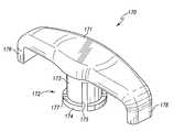
- FIG. 1is a perspective view of an exemplary embodiment of a one-level (1-L) static bone fixation plate fashioned in accordance with the principles of the present invention
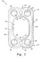
- FIG. 2is a bottom view of the one-level (1-L) static bone fixation plate of FIG. 1 ;
- FIG. 3is a perspective view of the one-level (1-L) static bone fixation plate of FIG. 1 but having a cover thereon fashioned in accordance with an aspect of the present invention
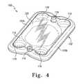
- FIG. 4is a perspective view of the one-level (1-L) static bone fixation plate of FIG. 1 having a contoured cover thereon fashioned in accordance with an aspect of the present invention
- FIG. 5is a perspective view of an exemplary embodiment of a two-level (2-L) static bone fixation plate fashioned in accordance with the principles of the present invention
- FIG. 6is a sectional view of the 2-L static bone fixation plate of FIG. 5 taken along line 6 - 6 thereof;
- FIG. 7is a sectional view of the 2-L static bone fixation plate of FIG. 5 taken along line 7 - 7 thereof;
- FIG. 8is a perspective view of a 2-L construct including the 2-L static bone fixation plate of FIG. 5 with bone plate screws and bone screw retention clips;
- FIG. 9is an enlarged perspective view of the bone screw retention clip depicted in FIG. 8 ;
- FIG. 10is a perspective view of an exemplary embodiment of a one-level (1-L) dynamic bone fixation plate fashioned in accordance with the principles of the present invention, the 1-L dynamic plate shown in an almost fully open or fully dynamic state;
- FIG. 11is a perspective view of an exemplary embodiment of a two-level (2-L) dynamic bone fixation plate fashioned in accordance with the principles of the subject invention, the 2-L dynamic plate shown with each end plate portion of the 2-L dynamic plate in exploded view relative to an intermediate plate portion of the 2-L dynamic plate;
- FIG. 12is a perspective view of an exemplary embodiment of another 2-L dynamic bone fixation plate fashioned in accordance with the principles of the subject invention, the 2-L dynamic plate shown with end plate portions thereof in an exploded position relative to an intermediate plate portion thereof in accordance with the principles of the subject invention; and
- FIG. 13is an enlarged sectional view of an exemplary constraining mechanism that may be utilized in the present dynamic plates.
- FIGS. 1 and 2there is depicted an exemplary one level (1-L), static cervical plate generally designated 100 , of which FIG. 1 is lateral perspective view of the plate 100 and FIG. 2 is a bottom plan view of the plate 100 .
- the plate 100is characterized by a body 102 formed of a suitable material such as is known for the manufacture of cervical plates, for example titanium, a titanium alloy or the like.
- the body 102is generally rectangular in shape and slightly curved on the underside thereof in order to mimic the natural curvature of a vertebra. Such curvature may be in one or two planes.
- the body 102may be manufactured in various sizes to accommodate vertebra of different sizes.
- the body 102has an opening, window, void or the like 104 (collectively hereinafter, window) in a middle, center or central portion of the body 102 bounded by surface 107 .
- windowmay be formed in various configurations, it is preferable that the window extend essentially from proximate to adjacent bone screw bores 106 that are situated on ends 121 , 123 of the 1-L plate 100 .
- the window 104is configured in a somewhat oblong shape defining a first peak 111 and a second peak 113 . As developed more fully below, the elongation of the window allows for better alignment of the plate 100 on the vertebra by the surgeon.
- the window 104itself provides visualization of the bone graft abutment to the posterior section of the plate while in situ.
- the opening 104defines a first leg 103 a and a second leg 103 b to the body 102 that extend between ends 121 and 123 of the body 102 .
- the length (l)is longer then the width (w) of the opening 104 .
- the length (l)is elongated or extended to span essentially between the edges of each screw bore 106 .
- the window/leg configurationcreates a “dual pillar” like support foundation for plate strength as between the first and second ends 121 , 123 , such as against twisting or flexing.
- the size and configuration of the window 104(forming two legs or a dual pillar configuration) provides an easy bone screw placement and/or allows for bone graft viewing.
- Each leg 103 a / 103 bpreferably, but not necessarily, has the same cross-sectional profile.
- the cross-sectional profile of each legis preferably, but not necessarily, consistent throughout its length between ends 121 , 123 .
- the legs 103 a / 103 bhave the same height profile as the overall plate body 102 .
- Each bone screw bore 106has a ledge 105 formed in the interior thereof.
- the ledge 105is configured to capture an undersurface of a head of a bone screw. As such, each ledge 105 is somewhat dish-shaped to accommodate the complementary shape of the undersurface of the bone screw head.
- Each ledge 105is also angled to allow the inserted bone screw to achieve a proper orientation during implantation.
- the bone screw bores 106are configured to utilize various types of bone screws such as fixed angle screws, emergency screws, and variable angle screws, examples of which are incorporated herewith through the parent provisional application.
- the bore/ledgeallows variable bone screw angulation while fixing or mounting the plate to the vertebrae. Such angulation is up to 30° cephalad—caudal, and 20° lateral—medial.
- the body 102further includes two bores 108 each one of which is situated proximate (here shown as between) bone screw bore pairs 106 of each end 121 and 123 .
- Each bore 108is configured to receive a boss or fastening device/portion of a bone screw retainer device, cover plate, retention clip, or the like such as described herein for preventing rotation and/or backout of a bone screw that has been implanted.
- FIG. 3there is depicted the 1-L static cervical plate 100 of FIGS. 1 and 2 , but shown with one embodiment of a bone screw anti-backout, rotation inhibitor and/or releasable locking mechanism, embodied as a cover, plate or the like 110 .
- the cover 110is situated on the plate 100 so as to cover the graft window 104 and at least partially the heads of the implanted bone screws.
- the cover 110is used with the plate 100 to provide an embodiment of a 1-L static cervical plate construct.
- the cover 110may be placed onto the body 102 . This covers the opening 104 , and most of the screw bores 106 .
- the cover 110is essentially flat, thus having a low profile.
- the cover 110moreover surrounds the window 104 and most of each bone screw bore 106 (which would be most of a bone screw head when so installed). This helps to keep, retain or releasably lock the bone screws from backing out and/or turning.
- the coveralso will provide protection against potential graft migrating out of the inter-vertebral space post operatively.
- the coverfurther will allow for post-operative visualization via radiograph.
- the cover 110includes two cover bosses 112 that are configured to provide a snap fit into plate bores 108 when installed, such that the cover 110 is retained on the plate 100 . While normal use will not cause the cover 110 to separate from body 102 , a simple tool may allow removal of the cover 110 .
- the cover 110is exemplary of the type of covers that may be used as bone screw locking mechanisms with the 1-L static cervical plate 100 . As such, covers 110 may be manufactured in various sizes to accommodate various sizes of cervical plates 110 .
- the cover 110is also fabricated from a biocompatible material like the material for the plate 100 .
- the plate 100may also accommodate other styles of covers.
- FIG. 4depicts an alternative cover 114 (bone screw locking mechanism and/or graft window/area cover) for the 1-L static cervical plate 100 of FIG. 1 .
- the cover 114includes two bosses 116 that are configured to be snap fit received in the plate bores 108 thus retaining the cover 114 onto the plate 100 .
- the cover 114extends over the opening 104 of the plate from over the leg 103 a to over the leg 103 b , and over each screw bore 106 of the body 102 .
- the cover 114includes a depression or concavity 120 that is configured like the opening 104 in order to extend into the opening 104 when the cover 114 is installed. Moreover, the cover 114 includes four screw bore depressions or concavities 118 each of which is configured to extend into one of the bone screw bores 106 of the body 102 of the plate 100 .
- the covers or cover platesmay be fashioned from an alloy of metals, titanium, a titanium alloy, PEEK, or suitable biocompatible material.
- FIGS. 1-4show a bone screw in use with the plate 100
- the plate 100is able to utilize various types of bone screws such as were set forth in the corresponding provisional application, incorporated above.
- the plate 100may utilize a polyaxial bone screw, a fixed bone screw, and an emergency bone screw.
- FIGS. 5-7there is depicted an exemplary embodiment of a two level (2-L) static cervical plate, generally designated 150 , incorporating the dual or twin pillar configuration for each level thereof such as described with reference to the 1-L plate 100 .
- the 2-L plateis designed to span between and be anchored to three vertebrae with a central window in accordance with the present principles between each fastening juncture thereof.
- the curved arrow relative to a horizontal lineillustrates two planes of curvature that the plate 100 may have mimicking the curvatures of vertebrae.
- a particular length and/or thickness cervical platemay also be manufactured with varying curvatures.
- the plate 150is defined by a body 152 that may be considered as having a middle portion or section 167 , a first end portion or section 166 on one side of the middle portion 167 , and a second end portion or section 168 on another side of the middle portion 167 .
- the middle portion 167defines a fastening, mounting or attachment portion that is adapted to be attached to a central vertebra of a three vertebrae fusion.
- the end portions 166 and 168also define a fastening, mounting or attachment portion that is adapted to be attached to separate outer vertebra of the three vertebrae fusion.
- the static 2-L plate 150includes dual (two) openings, windows, voids or the like 153 and 155 , one opening for each level or between each end portion 166 , 168 and the middle portion 167 .
- Each window 153 and 155is centrally, located defines leg pairs (pillars) 164 a / 164 b and 165 a / 165 b.
- the opening 153is disposed in the middle, center or central portion of the area between the end portion 166 and the middle portion 167 , being bounded by surface 154 .
- the window 153is configured in an exemplary fashion as an elongated oval that extends from just adjacent to a portion of each screw bore 157 of the end portion 166 (proximate the reception bore 160 of the end portion 166 ) to just adjacent to a portion of each screw bore 161 of the middle portion 167 (proximate the reception bore 160 of the middle portion 167 ).
- the opening 155is disposed in the middle, center or central portion of the area between the end portion 168 and the middle portion 167 , being bounded by surface 156 .
- the opening 155is configured as an elongated oval that extends from just adjacent to a portion of each screw bore 157 of the end portion 168 (proximate the reception bore 160 of the end portion 168 ) to just adjacent to a portion of each screw bore 161 of the middle portion 167 (proximate the reception bore 160 of the middle portion 167 ).
- the elongation of the openings 153 , 155allow for alignment of the plate 150 during surgery and mounting thereof by the surgeon.
- the size and configuration of the openings 153 , 155(forming two legs or a dual pillar configuration) provides easy bone screw placement and/or allows for bone graft viewing.
- Each leg pair 164 a / 164 b and 165 a / 165 bpreferably, but not necessarily, has the same cross-sectional profile.
- each leg 164 a/b and 165 a /bpreferably, but not necessarily has the same cross-sectional profile.
- the cross-sectional profile of each legis preferably, but not necessarily, consistent throughout its length between the middle portion 167 and end portions 166 and 168 .
- the legs 164 a/b and 165 a/bhave the same height profile as the overall plate body 152 .
- the ends 166 and 168each have two bone screw bores 157 each one of which is disposed on corners of the respective ends and at least partially defining the fastening portions.
- the ends 166 and 168each have an outer contour that defines a notch.
- Each bone screw bore 106is sized, configured and/or situated such that a portion thereof is adjacent a proximate portion of its respective opening 153 , 155 .
- Each bone screw bore 157has a ledge 158 formed in the interior thereof.
- Each ledge 158is configured to capture an undersurface of a head of a bone screw. As such, each ledge 158 is somewhat dish-shaped to accommodate the complementary shape of the undersurface of the bone screw head.
- Each ledge 158is also angled to allow the inserted bone screw to achieve a proper orientation during implantation.
- the bone screw bores 157are configured to utilize various types of bone screws as described above. Additionally, the bone screw bores 157 are configured to utilize various types of bone screws such as fixed angle screws, emergency screws, and variable angle screws, examples of which are incorporated herewith through the parent provisional application.
- the bore/ledgeallows variable bone screw angulation while fixing or mounting the plate to the vertebrae. Again, such angulation may be up to 30° cephalad—caudal, and 20° lateral—medial.
- the middle portion 167also has two bone screw bores 161 disposed as pairs of screw bores in like manner to the other screw bores at least partially defining the fastening portion.
- Each bone screw bore 161is sized, configured and/or situated such that a portion thereof is adjacent a proximate portion of an opening 153 , 155 .
- Each bone screw bore 161has a ledge 162 formed around the interior thereof.
- Each ledge 162is configured to capture an undersurface of a head of a bone screw.
- each ledge 158is somewhat dish-shaped to accommodate the complementary shape of the undersurface of the bone screw head.
- Each ledge 158is also designed to receive the inserted bone screw in a fairly straight manner to achieve a proper orientation during implantation.
- the bone screw bores 161are configured to utilize various types of bone screws like those above.
- the body 152further includes two bores 160 each one of which is situated between bone screw bore pairs 157 of each end portion 166 and 168 .
- An additional like bore 160is positioned in the middle portion 167 .
- Each bore 160is configured to receive a boss or fastener of a bone screw retainer device, cover plate, retention clip, or the like.
- the 2-L static cervical plate construct 159includes the 2-L static cervical plate 150 , bone screws 180 , and bone screw locking, retainer or retention clips, tabs or the like 170 (clips). Some of the bone screws 180 are depicted in various orientations relative to the plate 150 to illustrate the ability of the plate 150 to allow such variable orientations.
- the construct 159utilizes releasable bone screw locking means, anti-backing, retainer, retention or retaining clips or tabs 170 that attach onto and between pairs of screws 180 , particularly the pairs of screws for each body section 166 , 167 , 168 .
- the clips 170also attach to the plate body 152 . The clips 170 aid in preventing the backing out or rotation of the bone screws thus providing locking of the bone screws and to the cervical plate.
- the clip 170is depicted.
- the clip 170has been enlarged for clarity.
- the clip 170is formed of a biocompatible material preferably, but not necessarily, the same material as the cervical plates and/or cover plates.
- the clip 170is defined by a body 171 having a first prong 176 on one end thereof, a second prong 178 on a second end thereof, and a boss structure 172 .
- the body 171is sized such that the prongs 176 and 178 span the distance between bone screw heads.
- the boss structure 172is defined by a post 173 that extends from the underside of the body 171 .
- the postterminates in a rim 174 and includes one or more slots 175 .
- the post 173is configured to be received in the clip post (boss) bore 160 of the body 152 of the plate 150 (and other such situated bores in the other plates described herein) thus releasably retaining or locking the clip 170 to the plate 150 .
- Each prong 176 , 178is adapted to be received in a bone screw head socket.
- clips 170is not limited to static 2-L plates as shown, but may be used with static 1-L plates, static multi-level plates, and dynamic plates of all levels.
- the clip 170is provided in various sizes in order to be used with plates of various sizes, since the span between bone screw heads may be different for different size plates.
- the clip 170also has a low profile (thickness) so as to remain relatively flat against the plate 150 .
- the diameter of the post 173is slightly less than the diameter of the receiving bore in the plate (e.g. bore 160 of plate 150 ) so that the receiving bore may receive the post.
- the rim 174defines a diameter that is oversized for the receiving bore in the plate.
- the notches or slots 175allow the ends of the post 173 to slightly compress, reducing the effective diameter of the rim 174 , causing the rim 174 to pass through the receiving bore.
- the post 173returns to its uncompressed state such that the end 177 of the rim 174 contacts the underside of the plate, preventing the clip 170 from pulling out of the receiving bore without a special tool or the like.
- the resilient boss 174is thus configured to be releasably, but snugly snap or press fit received into an appropriate plate bore.
- Each bone screw 180has a head or head portion 181 .
- Each head 181includes a socket 182 formed therein.
- the socket 182is preferably, but not necessarily, configured in a polygonal pattern. Other configurations may be used.
- Each corner 182 of the polygon pattern(socket configuration) is rounded such that the span of the ends of the prongs 176 , 178 fits into two rounded corners 182 . In this manner the prongs 176 and 178 lock the bone screws from rotation.
- rotation of either bone screw of the bone screw pair fitted with a clip 170will slightly rotate the clip in the plane of the plate 150 thus binding the clip against each other.
- the clip 170is also releasably locked to the plate 150 .
- the boss 172 of the clip 170is situated in the bore 157 (snap-fit received).
- One prong 176extends into the socket 182 of the head 181 of the upper bone screw 180 while the other prong 178 extends into the socket 182 of the head 181 of the lower bone screw 180 .
- the prongsinteract with the polygon socket of the head to limit rotation of a screw.
- the first and second configured flanges 176 , 178are configured to be press or snap fit received in the bone screw head socket.
- FIG. 10depicts an exemplary embodiment of a dynamic 1-L cervical plate generally designated 200 , in accordance with the present principles.
- the dynamic 1-L plate 200is shown in exploded form to better illustrate the manner in which the dynamic plate is assembled, joined and/or is dynamic or dynamizes.
- the dynamic 1-L plate 200is characterized by a first section 202 and a second section 204 that when assembled or together provides an opening, void or window 117 .
- the size of the opening 117is variable depending on the position of the two sections 202 , 204 relative to one another.
- Each section 202 , 204defines a U-shape or portion that slidingly mates with one another to provide dynamization when attached.
- the sections 202 , 204each provide a fastening portion, one for each vertebra.
- the window 217exposes an area between the vertebrae. It should be appreciated that the configuration of such mating may be modified and/or deviate from that shown.
- the first section 202has a body 203 supporting two bone screw bores 206 which, while not shown, may include configured ledges such as the configured ledges 158 of bone screw bores 157 of plate 150 (see, e.g. FIG. 5 ) for variable bone screw angulation as described above.
- the first section 202also includes first and second legs 208 and 211 .
- the first leg 208has a configured channel 209 extending therein.
- the second leg 211also has a configured channel 210 extending therein. While not necessary, the first and second channels 209 , 210 are preferably the same configuration, but may be of one each such that the device is 180° rotatable and be the same.
- the second section 204has a body 205 supporting two bone screw bores 218 , which, while not shown, may include configured ledges such as the configured ledges 158 of bone screw bores 157 of plate 150 (see, e.g. FIG. 5 ).
- the second section 204also includes first and second configured arms 214 , 216 .
- the first configured arm 214is configured and/or dimensioned in like manner to the channel 209 and thus to be slidingly receivable into the configured channel 209 .
- the second configured arm 216is also configured and/or dimensioned in like manner to the channel 210 and thus to be slidingly receivable into the configured channel 211 .
- the arms 214 , 216are of a length to be fully received in the respective channel 209 , 211 so the ends of the legs 208 , 210 abut the ends of the arms 214 , 216 .
- the dynamic 1-L plate 200 of FIG. 10provides relative movement between the two sections or components 202 , 204 .
- FIG. 11there is depicted an exemplary embodiment of a dynamic two level (2-L) plate generally designated 230 formed in accordance with an aspect of the subject invention.
- the dynamic 2-L plate 230is shown in exploded form to better illustrate the manner in which the dynamic plate is assembled, joined and/or is dynamic or dynamizes.
- Thisalso illustrates how the middle plate component 250 may be used with itself to form n-levels of cervical plates with end components (i.e. two end plate components 232 for attachment to beginning and end vertebrae, and n middle plate components 250 defining the n-levels for attachment to n number of middle vertebrae), and moreover with each level providing dynamization (internally dynamizing).
- each internal or middle sectionis dynamizing as between themselves, not just the end plate components relative to a middle portion.
- the dynamic 1-L plate 200is characterized by a first section 202 and a second section 204 that when assembled or together provides an opening, void or window 117 .
- the size of the opening 117is variable depending on the position of the two sections 202 , 204 relative to one another.
- Each section 202 , 204defines a U-shape or portion that slidingly mates with one another to provide dynamization when attached. This sliding motion is unconstrained such that it smoothly transitions between various positions without ratchets or the like.
- the sections 202 , 204each provide a fastening portion, one for each vertebra.
- the window 217exposes an area between the vertebrae. It should be appreciated that the configuration of such mating may be modified and/or deviate from that shown.
- the dynamic plate 230has extended windows or openings formed by the dual pillar structure and, more particularly, has two windows formed by two dual pillar structures.
- the dynamic plate 230is a two level (2-L) plate that is composed of three components which are shown in exploded view relative to one another in FIG. 11 .
- the plate 230is formed of a middle plate component 250 and two end plate components 232 a and 232 b .
- the two end plate components 232 a and 232 bare identical.
- a 180° reversal of an end component 232in conjunction with the configuration of the middle component 250 , allows the dynamic 2-L plate to utilize only two different pieces. Therefore, kits to provide n-level plates would come with two end plate components, and a plurality of middle plate components.
- End component 232 ais defined by a body 233 a having bone screw bores 235 a and configured ledges 234 a such as described above.
- a retention bore 236 a for a locking clip 170 or cover plate bossis provided between the two bone screw bores.
- the body 233 adefines a first leg 238 a having a configured channel or cutout 237 a therein.
- the shape of the channel 237 aprovides lateral and up/down stability to a joining or mating piece of the middle component 250 .
- the configuration of the channelmay be changed as appropriate under the present principles.
- the channel 237 ais configured akin to a dovetail.
- a second leg 244 a of the body 233 ais configured akin to the channel 237 a dovetail. It should be observed that the end components 232 a and 232 b may be joined or assembled into a dynamic 1L plate without the use of the middle component 250 since the leg 244 b (identical to leg 244 a ) will be received in leg channel 237 a while the leg 244 a will be received in leg channel 237 b (identical to leg channel 237 a ).
- the end component 234 bis defined by a body 233 b having bone screw bores 235 b and configured ledges 234 b such as described above.
- a retention bore 236 b for a retention clip or cover bossis provided between the two bone screw bores.
- the body 233 bdefines a first leg 238 b having a configured channel or cutout 237 b therein.
- the shape of the channel 237 bprovides lateral and up/down stability to a joining or mating piece of the middle component 250 .
- the configuration of the channelmay be changed as appropriate under the present principles.
- the channel 237 bis configured akin to a dovetail.
- a second leg 244 b of the body 233 bis configured akin to the channel 237 b dovetail.
- the middle or expansion component 250is defined by a body 252 having two bone screw bores 254 having head seats 255 , and a boss bore 256 .
- the body 252also includes a first leg 258 having a configured channel 260 therein.
- the channel 260receives the configured leg 244 a of the section 232 a (or flange 272 of another expansion component) and is thus configured appropriately.
- a second leg 262 of the body 252includes a configured flange 264 that is configured to be received in the channel 237 a of the section 230 (or a channel 268 of another expansion component) and is thus configured appropriately.
- a third leg 270includes the configured flange 272 receivable in the channel 237 b of the section 232 b (or in the channel 260 of another expansion component).
- a fourth leg 266 of the body 252includes the channel 268 that receives the configured flange 244 of the section 230 or the flange 264 of another expansion device.
- This structure and/or interrelationship of the middle component 250 to itself and to the end components 232provides the ability to assemble N-level, dynamic plates.
- the 2-L dynamic plate 230when assembled, defines first and second windows, voids or openings 275 , 277 between the middle component 250 and each end component 232 .
- the legs and flanges when assembledeach have the same cross-section.
- the truncated triangle cross-sectionprovides loading stability.
- FIG. 12depicts another exemplary embodiment of a dynamic two-level cervical plate, generally designated 300 , that is a variation of the dynamic two-level cervical plate 230 but which incorporates the features and/or functions of the plate 230 .
- the 2-L plate 300has components that can be assembled to form a 1-L plate or an n-level plate.
- the plate 300is formed of a middle component 302 and first and second identical end components 304 a , 304 b .
- the dynamic plate 300has extended windows or openings formed by dual pillar structures.
- the dynamic plate 300is a two level (2-L) plate that is composed of three components which are shown assembled in FIG. 11 .
- the plate 300is formed of a middle plate component 302 and two end plate components 304 a and 304 b .
- the two end plate components 304 a and 304 bare identical.
- a 180° reversal of an end component 304in conjunction with the configuration of the middle component 302 , allows the dynamic 2-L plate to utilize only two different pieces.
- End components 304 a/bis defined by a body 333 a/b having bone screw bores 335 a/b and configured ledges 334 a/b such as described above.
- a retention bore 336 a/b for a retention clip or cover bossis provided between the two bone screw bores.
- the body 333 a/bdefines a first leg 338 a/b having a configured mating structure thereon.
- the body 333 a/balso defines a thickened second let 340 a/b that has a channel for receiving a like configured leg portion of the middle component 302 , the shape of which provides lateral and up/down stability to a joining or mating piece of the middle component 302 .
- the configuration of the channelmay be changed as appropriate under the present principles. It should be observed that the end components 304 a and 304 b may be joined or assembled into a dynamic 1L plate without the use of the middle component 302 .
- the middle or expansion component 302is defined by a body 352 having two bone screw bores 354 having head seats 355 , and a boss bore 356 .
- the body 352also includes a first thickened leg 358 having a channel therein that is configured to receive the configured leg 338 a of the end component 304 a (or flange 366 of another middle component 350 ) and is thus configured appropriately.
- a second leg 364 of the body 352includes a flange that is configured to be received in the channel structure 340 a of the end component 304 a (or a channel 366 of another middle component) and is thus configured appropriately.
- a third leg 372includes configured flange receivable in the channel structure 340 b of the end section 232 b (or in the channel of another middle component).
- a fourth leg 366 of the body 352includes a channel structure that receives the configured flange 338 b of the end component 304 b or the flange of another middle component. This structure and/or interrelationship of the middle component 302 to itself and to the end components 304 , provides the ability to assemble N-level, dynamic plates.
- the 2-L dynamic plate 300when assembled, defines first and second windows, voids or openings 308 , 310 between the middle component 302 and each end component 304 .
- the legs and flanges when assembledeach have the same cross-section.
- the various dynamic plates of the present inventionare assembled from a number of end and middle components depending on the desired plate level.
- the various componentsare slidingly interconnected to one another. It should be appreciated that once assembled, the plate components, while slidable with respect to each other, have a disassembly stop or constraining mechanism or device such that the plate components will not disassemble once assembled.
- the disassembly constraining mechanismconstrains or limits the length of travel of the leg assemblies (slidingly connected legs of the plate components) of the two plate components relative to one another in a disassembled direction of travel.
- FIG. 13illustrates an enlarged portion of two slidingly interconnected legs 380 , 382 of any two assembled dynamic plate components according to the principles of the present invention.
- Leg 380may be a configured leg with a channel or groove, while the leg 382 is a configured leg with a flange, or vice versa such as described herein.
- the arm 380will arbitrarily considered a configured channel arm and the arm 382 necessarily considered the configured flange arm. It should also be appreciated that distances and lengths are not necessarily to scale and/or in proportion with one another.
- the channeled arm 380has a detent 384 within the groove (the underside per FIG. 13 ) of the arm 380 .
- the detent 384extends a distance from the groove surface into the are 385 and is preferably, but not necessarily, in the form of a right triangle having a sharp to rounded apex.
- the flanged arm 382includes a notched or cutout area or portion 385 bounded by a ledge 388 .
- a detent 386again preferably, but not necessarily in the form of a right triangle having a sharp to rounded apex, is situated within the area 385 .
- the detent 386is to the left of detent 384 . While the height of the detents are such that the apex of each detent extends beyond the apex of the other detent, as the two detents 384 , 386 meet their angled or ramped surfaces meet. Continued travel allow the ramps to slide relative to another. The small overlap in detent height thus allows the detent 384 to reside in area 385 once full assembly has taken place. In one direction of travel, the detent 384 will contact ledge 388 , while in the other direction the difference in detent height creates a stop. Of course, other types of stop mechanisms may be employed that allow assembly but prevents disassembly or makes disassembly extremely difficult.
- the cervical plates described aboveare intended for anterior screw fixation to the cervical spine (C2 through T1) for various conditions such as at least the conditions of spondylolisthesis, fracture, spinal stenosis, and tumor.
- the configuration(s) and/or principles of the 1-L dynamic plate(s) described hereinare applicable to and/or may be used in the various 2-L dynamic plates also described herein.
- 2-L dynamic plate configurations described hereinmay be used in the 1-L plates described herein. This is particularly true with respect to the various leg or projection configurations and the sliding connectivity thereof.
- Each plateis preferably, but not necessarily, formed from titanium (e.g. titanium 6A1-4V ELI per AASTM F-136). Other suitable metals, ceramics may be used if appropriate.
- the preferred embodiment of the present cervical plateswill embody curvature in two planes (sagittal and coronal) to more closely resemble the anatomical aspects of the spine.
- the cervical platesmay be provided without curvature or with curvature in one plane as necessary.
- the platesare made in various sizes (e.g. 14 mm through 110 mm) to accommodate various spines.
- the plateshave a nominal thickness of about 1.8 mm to 3.0 mm and a width of about 18 mm.
- the platesare configured to accept bone screws having a diameter of about 4.0 through 4.5 mm.
- the bone screw holes of the platesare configured to accommodate both static and variable angle bone screws. This is accomplished by use of a unique pocket design of the bone screw holes.
- the bone screwsare affixed using a typical screw driver (e.g. hexalobullar driver, ⁇ 10).
- a single locking platelocks a pair of screws.
- the locking plateincludes a center post that locks into a cover plate bore in the plate, and which has two configured flanges that are received in the head of the screw.
- the coverincludes integral locking flanges for the bone screws.
- the cover and/or locking flangesare preferably made of PEEK, plastic, alloy or titanium.
- a platemay be utilized as follows. A plate is placed onto the anterior aspect of a vertebral body of the cervical spine by inserting a 4.0 mm cancellous bone screw or a 4.3 mm expansion screw through the cephalad holes and into the vertebral body. The screw or expansion screws are then inserted into the caudal holes in the plate and inserted into the vertebral bodies of the cervical spine. The locking mechanisms are then inserted in a single step over the entire plate (e.g. a cover), or two locking mechanism are inserted over each set of screws (cephalad and caudel). The locking mechanisms will snap into place.
- the present inventionalso provides for dynamically fusing the cervical spine of a patient via various methods, particularly, but not necessarily, utilizing a cervical plate as described herein.
- One such methodincludes the opening of an access aperture in the patient to permit access to an appropriate area of the cervical spine of the patient.
- a vertebral discis removed between each vertebrae (level) as appropriate (e.g. one disc for a 1-L, two discs for a 2-L, etc.). Bone graft is then sized for placement into the space where the spinal disc has been removed.
- a dynamic cervical platesuch as any described herein, is selected for implanting onto the spine (vertabrae).
- the selected dynamic cervical plateis sized to allow for the best anatomical settling (motion), e.g.
- the selected and sized dynamic plateis placed over the inserted bone graft(s) onto the vertebrae.
- the graft(s)is then visualized through the window(s) within the dynamic plate for proper fitment.
- Each sectionis accomplished in sequence for proper fitment.
- the plateis secured onto the spine by bone screws placed through the bone screw bores within the plate components or segments. After each bone screw is attached, a locking mechanism is installed onto/over the bone screws/plate. The aperture is then closed.
- Another method of dynamically fusing the cervical spineincludes providing a dynamic cervical plate wherein the end components of the provided dynamic cervical plate move relative to one another utilizing multiple projections (e.g. legs) sliding into or over one another according to the principles of the present invention.
- Another method of dynamically fusing the cervical spineincludes providing a dynamic cervical plate wherein the end components of the provided dynamic cervical plate move relative to a middle segment/component utilizing multiple projections (e.g. legs) sliding into or over one another according to the principles of the present invention.
- Another method of dynamically fusing the cervical spineincludes providing a dynamic cervical plate wherein the middle segments/components of the provided dynamic cervical plate move relative to one another utilizing multiple projections (e.g. legs) sliding into or over one another according to the principles of the present invention.
- Each plateproviding a central graft window as provided herein for each level thereof.
- any of the methodsmay include the providing of an n-level dynamic cervical plate, plate construct, or plate kit, wherein the end segments are 180° interchangeable, middle segments are 180° interchangeable, the end segments and the middle segments are 180° interchangeable, the end segments and the middle segments move 0 to 4 mm independent of the movement of one another, and/or the movement of the end segments and the middle segments is unconstrained.
- the subject inventionprovides several key attributes that other plates and/or plate systems do not including:
- the screw holeshave a unique geometry allowing a simple change of screws to utilize the plate as a variable angle screw/plate construct or as a fixed angle screw plate construct.
- the plate constructmay utilize an optional bone screw locking mechanism.
- the optional screw locking mechanismis a single-piece, snap on cover that is preferably, but not necessarily, made of PEEK or Titanium.
- the optional screw locking mechanismattaches into the cervical plate by one of the midline holes.
- the locking mechanismwill cover two screws at one time and lock into the plate using a pronged shaft.
- Radial projections(propeller like structures) have teeth on the extended ends that mate with the corresponding screws. The teeth lock into the lobes within the screw preventing them from both turning and backing out. This mechanism, like the other, snaps into place but remains removable with the proper instrument.
- the dynamic plate form of the present inventionwill allow the fused vertebral bodies to settle onto the graft centered between them. This new dynamic plate and technique will allow fused segments to move, settle or subside which will provide for more constant bone-graft-bone contact.
- the present dynamic plate designallows the settling to occur in an anatomical fashion, due to plate curvatures. The bodies will translate in stabilized directions on two separate planes (pure translation).
- the present inventionprovides the ability to control subsidence of the plate. This is important in order to prevent the plate from migrating into the healthy adjacent disc space. Moreover the present invention aids in preventing the destruction of the host endplate or the graft from unmitigated settling that may lead to pseudarthrosis. It should be appreciated that the above description is only exemplary of the principles of the subject invention. Therefore, other embodiments are contemplated and within the present scope.
Landscapes
- Health & Medical Sciences (AREA)
- Orthopedic Medicine & Surgery (AREA)
- Life Sciences & Earth Sciences (AREA)
- Surgery (AREA)
- Neurology (AREA)
- Heart & Thoracic Surgery (AREA)
- Engineering & Computer Science (AREA)
- Biomedical Technology (AREA)
- Nuclear Medicine, Radiotherapy & Molecular Imaging (AREA)
- Medical Informatics (AREA)
- Molecular Biology (AREA)
- Animal Behavior & Ethology (AREA)
- General Health & Medical Sciences (AREA)
- Public Health (AREA)
- Veterinary Medicine (AREA)
- Surgical Instruments (AREA)
- Prostheses (AREA)
Abstract
Description
Claims (15)
Priority Applications (1)
| Application Number | Priority Date | Filing Date | Title |
|---|---|---|---|
| US11/022,504US8182518B2 (en) | 2003-12-22 | 2004-12-21 | Static and dynamic cervical plates and cervical plate constructs |
Applications Claiming Priority (2)
| Application Number | Priority Date | Filing Date | Title |
|---|---|---|---|
| US53165703P | 2003-12-22 | 2003-12-22 | |
| US11/022,504US8182518B2 (en) | 2003-12-22 | 2004-12-21 | Static and dynamic cervical plates and cervical plate constructs |
Publications (2)
| Publication Number | Publication Date |
|---|---|
| US20050149026A1 US20050149026A1 (en) | 2005-07-07 |
| US8182518B2true US8182518B2 (en) | 2012-05-22 |
Family
ID=34738676
Family Applications (3)
| Application Number | Title | Priority Date | Filing Date |
|---|---|---|---|
| US11/022,504Active2028-07-25US8182518B2 (en) | 2003-12-22 | 2004-12-21 | Static and dynamic cervical plates and cervical plate constructs |
| US11/022,461Expired - LifetimeUS7318825B2 (en) | 2003-12-22 | 2004-12-22 | Dynamic cervical plates and cervical plate constructs |
| US12/008,550AbandonedUS20080114361A1 (en) | 2003-12-22 | 2008-01-11 | Dynamic cervical plates and cervical plate constructs |
Family Applications After (2)
| Application Number | Title | Priority Date | Filing Date |
|---|---|---|---|
| US11/022,461Expired - LifetimeUS7318825B2 (en) | 2003-12-22 | 2004-12-22 | Dynamic cervical plates and cervical plate constructs |
| US12/008,550AbandonedUS20080114361A1 (en) | 2003-12-22 | 2008-01-11 | Dynamic cervical plates and cervical plate constructs |
Country Status (6)
| Country | Link |
|---|---|
| US (3) | US8182518B2 (en) |
| EP (3) | EP1711114A4 (en) |
| JP (3) | JP2007515258A (en) |
| AT (1) | ATE520364T1 (en) |
| AU (2) | AU2004308422B2 (en) |
| WO (2) | WO2005062900A2 (en) |
Cited By (13)
| Publication number | Priority date | Publication date | Assignee | Title |
|---|---|---|---|---|
| US9028498B2 (en) | 2013-03-14 | 2015-05-12 | Innovasis, Inc. | Modular bone fixation plate assembly |
| US9468479B2 (en) | 2013-09-06 | 2016-10-18 | Cardinal Health 247, Inc. | Bone plate |
| US9504584B1 (en) | 2011-01-28 | 2016-11-29 | Nuvasive, Inc. | Spinal fusion implant and related methods |
| AU2018202756B2 (en)* | 2015-07-13 | 2019-05-02 | Crossroads Extremity Systems, Llc | Bone plates with dynamic elements |
| US10492841B2 (en) | 2014-07-10 | 2019-12-03 | Crossroads Extremity Systems, Llc | Bone implant and means of insertion |
| US10945725B2 (en) | 2017-02-06 | 2021-03-16 | Crossroads Extremity Systems, Llc | Implant inserter |
| US11179149B2 (en) | 2017-02-07 | 2021-11-23 | Crossroads Extremity Systems, Llc | Counter-torque implant |
| US11202626B2 (en) | 2014-07-10 | 2021-12-21 | Crossroads Extremity Systems, Llc | Bone implant with means for multi directional force and means of insertion |
| US11298244B2 (en) | 2019-01-31 | 2022-04-12 | K2M, Inc. | Interbody implants and instrumentation |
| USD961081S1 (en) | 2020-11-18 | 2022-08-16 | Crossroads Extremity Systems, Llc | Orthopedic implant |
| US11534307B2 (en) | 2019-09-16 | 2022-12-27 | K2M, Inc. | 3D printed cervical standalone implant |
| US11871899B2 (en) | 2013-12-20 | 2024-01-16 | Crossroads Extremity Systems, Llc | Bone plates with dynamic elements |
| US12059183B2 (en) | 2020-07-31 | 2024-08-13 | Crossroads Extremity Systems, Llc | Bone plates with dynamic elements and screws |
Families Citing this family (285)
| Publication number | Priority date | Publication date | Assignee | Title |
|---|---|---|---|---|
| US7833250B2 (en) | 2004-11-10 | 2010-11-16 | Jackson Roger P | Polyaxial bone screw with helically wound capture connection |
| US10729469B2 (en) | 2006-01-09 | 2020-08-04 | Roger P. Jackson | Flexible spinal stabilization assembly with spacer having off-axis core member |
| US7862587B2 (en) | 2004-02-27 | 2011-01-04 | Jackson Roger P | Dynamic stabilization assemblies, tool set and method |
| US8292926B2 (en) | 2005-09-30 | 2012-10-23 | Jackson Roger P | Dynamic stabilization connecting member with elastic core and outer sleeve |
| US8353932B2 (en) | 2005-09-30 | 2013-01-15 | Jackson Roger P | Polyaxial bone anchor assembly with one-piece closure, pressure insert and plastic elongate member |
| US10258382B2 (en) | 2007-01-18 | 2019-04-16 | Roger P. Jackson | Rod-cord dynamic connection assemblies with slidable bone anchor attachment members along the cord |
| US20060129151A1 (en)* | 2002-08-28 | 2006-06-15 | Allen C W | Systems and methods for securing fractures using plates and cable clamps |
| US8876868B2 (en) | 2002-09-06 | 2014-11-04 | Roger P. Jackson | Helical guide and advancement flange with radially loaded lip |
| WO2006052796A2 (en) | 2004-11-10 | 2006-05-18 | Jackson Roger P | Helical guide and advancement flange with break-off extensions |
| US7094238B2 (en)* | 2002-11-22 | 2006-08-22 | Sdgi Holdings, Inc. | Variable angle adaptive plate |
| US7621918B2 (en) | 2004-11-23 | 2009-11-24 | Jackson Roger P | Spinal fixation tool set and method |
| US8540753B2 (en) | 2003-04-09 | 2013-09-24 | Roger P. Jackson | Polyaxial bone screw with uploaded threaded shank and method of assembly and use |
| US8613772B2 (en)* | 2003-04-21 | 2013-12-24 | Rsb Spine Llc | Lateral mount implant device |
| US7377923B2 (en) | 2003-05-22 | 2008-05-27 | Alphatec Spine, Inc. | Variable angle spinal screw assembly |
| US7776067B2 (en) | 2005-05-27 | 2010-08-17 | Jackson Roger P | Polyaxial bone screw with shank articulation pressure insert and method |
| US8092500B2 (en) | 2007-05-01 | 2012-01-10 | Jackson Roger P | Dynamic stabilization connecting member with floating core, compression spacer and over-mold |
| US7967850B2 (en) | 2003-06-18 | 2011-06-28 | Jackson Roger P | Polyaxial bone anchor with helical capture connection, insert and dual locking assembly |
| US8366753B2 (en) | 2003-06-18 | 2013-02-05 | Jackson Roger P | Polyaxial bone screw assembly with fixed retaining structure |
| US8926670B2 (en) | 2003-06-18 | 2015-01-06 | Roger P. Jackson | Polyaxial bone screw assembly |
| US7766915B2 (en) | 2004-02-27 | 2010-08-03 | Jackson Roger P | Dynamic fixation assemblies with inner core and outer coil-like member |
| US20050049595A1 (en)* | 2003-09-03 | 2005-03-03 | Suh Sean S. | Track-plate carriage system |
| US7909860B2 (en) | 2003-09-03 | 2011-03-22 | Synthes Usa, Llc | Bone plate with captive clips |
| US7857839B2 (en) | 2003-09-03 | 2010-12-28 | Synthes Usa, Llc | Bone plate with captive clips |
| US8105367B2 (en) | 2003-09-29 | 2012-01-31 | Smith & Nephew, Inc. | Bone plate and bone plate assemblies including polyaxial fasteners |
| US7255714B2 (en) | 2003-09-30 | 2007-08-14 | Michel H. Malek | Vertically adjustable intervertebral disc prosthesis |
| US7306605B2 (en) | 2003-10-02 | 2007-12-11 | Zimmer Spine, Inc. | Anterior cervical plate |
| US7862586B2 (en) | 2003-11-25 | 2011-01-04 | Life Spine, Inc. | Spinal stabilization systems |
| US11419642B2 (en) | 2003-12-16 | 2022-08-23 | Medos International Sarl | Percutaneous access devices and bone anchor assemblies |
| US7179261B2 (en) | 2003-12-16 | 2007-02-20 | Depuy Spine, Inc. | Percutaneous access devices and bone anchor assemblies |
| US7527638B2 (en) | 2003-12-16 | 2009-05-05 | Depuy Spine, Inc. | Methods and devices for minimally invasive spinal fixation element placement |
| US8182518B2 (en)* | 2003-12-22 | 2012-05-22 | Life Spine, Inc. | Static and dynamic cervical plates and cervical plate constructs |
| US7678137B2 (en) | 2004-01-13 | 2010-03-16 | Life Spine, Inc. | Pedicle screw constructs for spine fixation systems |
| ITRM20040082A1 (en) | 2004-02-16 | 2004-05-16 | Sic Brevetti S R L | POST STERNOTOMY OR STERNAL FRACTURE REINFORCEMENT DEVICE. |
| US9451990B2 (en)* | 2004-02-17 | 2016-09-27 | Globus Medical, Inc. | Facet joint replacement instruments and methods |
| US11241261B2 (en) | 2005-09-30 | 2022-02-08 | Roger P Jackson | Apparatus and method for soft spinal stabilization using a tensionable cord and releasable end structure |
| US8152810B2 (en) | 2004-11-23 | 2012-04-10 | Jackson Roger P | Spinal fixation tool set and method |
| JP2007525274A (en) | 2004-02-27 | 2007-09-06 | ロジャー・ピー・ジャクソン | Orthopedic implant rod reduction instrument set and method |
| US7160300B2 (en) | 2004-02-27 | 2007-01-09 | Jackson Roger P | Orthopedic implant rod reduction tool set and method |
| US8236034B2 (en) | 2004-04-19 | 2012-08-07 | Globus Medical, Inc. | Bone fixation plate |
| US7963981B2 (en)* | 2004-04-19 | 2011-06-21 | Globus Medical, Inc. | Bone fixation plate |
| US7744635B2 (en)* | 2004-06-09 | 2010-06-29 | Spinal Generations, Llc | Spinal fixation system |
| US7938848B2 (en)* | 2004-06-09 | 2011-05-10 | Life Spine, Inc. | Spinal fixation system |
| US7604638B2 (en)* | 2004-06-21 | 2009-10-20 | Depuy Spine, Inc. | Instruments and methods for holding a bone plate |
| WO2006034436A2 (en) | 2004-09-21 | 2006-03-30 | Stout Medical Group, L.P. | Expandable support device and method of use |
| US7651502B2 (en) | 2004-09-24 | 2010-01-26 | Jackson Roger P | Spinal fixation tool set and method for rod reduction and fastener insertion |
| US9615866B1 (en) | 2004-10-18 | 2017-04-11 | Nuvasive, Inc. | Surgical fixation system and related methods |
| US7621914B2 (en)* | 2004-10-28 | 2009-11-24 | Biodynamics, Llc | Adjustable bone plate |
| US8926672B2 (en) | 2004-11-10 | 2015-01-06 | Roger P. Jackson | Splay control closure for open bone anchor |
| US8444681B2 (en) | 2009-06-15 | 2013-05-21 | Roger P. Jackson | Polyaxial bone anchor with pop-on shank, friction fit retainer and winged insert |
| WO2006057837A1 (en) | 2004-11-23 | 2006-06-01 | Jackson Roger P | Spinal fixation tool attachment structure |
| US9216041B2 (en) | 2009-06-15 | 2015-12-22 | Roger P. Jackson | Spinal connecting members with tensioned cords and rigid sleeves for engaging compression inserts |
| US9980753B2 (en) | 2009-06-15 | 2018-05-29 | Roger P Jackson | pivotal anchor with snap-in-place insert having rotation blocking extensions |
| US9168069B2 (en) | 2009-06-15 | 2015-10-27 | Roger P. Jackson | Polyaxial bone anchor with pop-on shank and winged insert with lower skirt for engaging a friction fit retainer |
| WO2006058221A2 (en) | 2004-11-24 | 2006-06-01 | Abdou Samy M | Devices and methods for inter-vertebral orthopedic device placement |
| US10076361B2 (en) | 2005-02-22 | 2018-09-18 | Roger P. Jackson | Polyaxial bone screw with spherical capture, compression and alignment and retention structures |
| US7901437B2 (en) | 2007-01-26 | 2011-03-08 | Jackson Roger P | Dynamic stabilization member with molded connection |
| WO2006096273A2 (en)* | 2005-03-03 | 2006-09-14 | Accelerated Innovation, Llc | Methods and apparatus for providing a retainer for a bone stabilization device |
| US7527641B2 (en)* | 2005-03-11 | 2009-05-05 | Synthes Usa, Llc | Translational hinged door plate system |
| US7749256B2 (en)* | 2005-04-05 | 2010-07-06 | Warsaw Orthopedic, Inc. | Ratcheting fixation plate |
| US8070749B2 (en)* | 2005-05-12 | 2011-12-06 | Stern Joseph D | Revisable anterior cervical plating system |
| WO2006124273A2 (en)* | 2005-05-12 | 2006-11-23 | Stern Joseph D | Revisable anterior cervical plating system |
| US7686806B2 (en)* | 2005-06-15 | 2010-03-30 | Stryker Spine | Anterior cervical plate |
| US20070055250A1 (en)* | 2005-07-11 | 2007-03-08 | Kamran Aflatoon | Cervical plates with spacer mechanism |
| EP1903949A2 (en) | 2005-07-14 | 2008-04-02 | Stout Medical Group, L.P. | Expandable support device and method of use |
| CA2616798C (en) | 2005-07-25 | 2014-01-28 | Smith & Nephew, Inc. | Systems and methods for using polyaxial plates |
| US8382807B2 (en) | 2005-07-25 | 2013-02-26 | Smith & Nephew, Inc. | Systems and methods for using polyaxial plates |
| US8062294B2 (en) | 2005-09-15 | 2011-11-22 | Spineform Llc | Implant with integral fastener retention |
| US8105368B2 (en) | 2005-09-30 | 2012-01-31 | Jackson Roger P | Dynamic stabilization connecting member with slitted core and outer sleeve |
| US20070123881A1 (en)* | 2005-10-26 | 2007-05-31 | Ralph James D | Off-set bone plates |
| FR2894130B1 (en)* | 2005-12-05 | 2012-07-13 | Spineart Sa | CAGES OF CONTENTION AND INTERSOMATIC FUSION OF VERTEBRATES |
| US9119677B2 (en) | 2005-12-09 | 2015-09-01 | DePuy Synthes Products, Inc. | Spinal plate and drill guide |
| US7704271B2 (en) | 2005-12-19 | 2010-04-27 | Abdou M Samy | Devices and methods for inter-vertebral orthopedic device placement |
| US8551145B2 (en)* | 2005-12-19 | 2013-10-08 | Mayo Foundation For Medical Education And Research | Anterior adherent thoracolumbar spine plate |
| EP1962707A1 (en)* | 2005-12-21 | 2008-09-03 | Synthes GmbH | Resorbable anterior cervical plating system with screw retention mechanism |
| EP1971282A2 (en) | 2006-01-10 | 2008-09-24 | Life Spine, Inc. | Pedicle screw constructs and spinal rod attachment assemblies |
| US7695473B2 (en)* | 2006-01-18 | 2010-04-13 | Biodynamics Llc | Adjustable bone plate |
| WO2007098188A2 (en)* | 2006-02-21 | 2007-08-30 | Life Spine, Inc. | Structure for joining and retaining multi-part orthopedic implants |
| US7641675B2 (en)* | 2006-03-08 | 2010-01-05 | Warsaw Orthopedic, Inc. | Flexible bone plates and methods for dynamic spinal stabilization |
| US20070233108A1 (en)* | 2006-03-15 | 2007-10-04 | Stalcup Gregory C | Spine fixation device |
| WO2007123979A2 (en) | 2006-04-18 | 2007-11-01 | University Of South Florida | Cervical plate system |
| GB2437492B (en)* | 2006-04-29 | 2009-06-24 | Dr Ahmad Fahmi Juanroyee | Multifragment plating system (MFPS) |
| EP2023864B1 (en) | 2006-05-01 | 2019-07-10 | Stout Medical Group, L.P. | Expandable support device |
| US20070276490A1 (en)* | 2006-05-15 | 2007-11-29 | Mateyka Richard J | Dynamic Spinal Plate Implant and Method of Use |
| US20120232595A1 (en) | 2011-03-07 | 2012-09-13 | Tyler HOLSCHLAG | Fastener retention system for spinal plates |
| ES2611609T3 (en)* | 2006-06-30 | 2017-05-09 | Alphatec Spine, Inc. | Bone fixation plate systems |
| WO2008014337A2 (en)* | 2006-07-28 | 2008-01-31 | Mmsn Limited Partnership | Bone anchor device |
| US20080039847A1 (en)* | 2006-08-09 | 2008-02-14 | Mark Piper | Implant and system for stabilization of the spine |
| US8317841B2 (en)* | 2006-09-26 | 2012-11-27 | Bray Jr Robert S | Cervical dynamic stabilization system |
| USD582040S1 (en)* | 2006-10-05 | 2008-12-02 | Stryker Spine | Cervical plate |
| USD581535S1 (en)* | 2006-10-05 | 2008-11-25 | Stryker Spine | Cervical plate |
| US7674279B2 (en)* | 2006-10-13 | 2010-03-09 | Spinal U.S.A. | Bone plate |
| US8262710B2 (en)* | 2006-10-24 | 2012-09-11 | Aesculap Implant Systems, Llc | Dynamic stabilization device for anterior lower lumbar vertebral fusion |
| US8206390B2 (en) | 2006-11-02 | 2012-06-26 | Warsaw Orthopedic, Inc. | Uni-directional ratcheting bone plate assembly |
| CA2670988C (en) | 2006-12-08 | 2014-03-25 | Roger P. Jackson | Tool system for dynamic spinal implants |
| US8475498B2 (en) | 2007-01-18 | 2013-07-02 | Roger P. Jackson | Dynamic stabilization connecting member with cord connection |
| US8366745B2 (en) | 2007-05-01 | 2013-02-05 | Jackson Roger P | Dynamic stabilization assembly having pre-compressed spacers with differential displacements |
| US20080234680A1 (en)* | 2007-01-26 | 2008-09-25 | Structure Medical, Inc. | Interlock for dynamic bone fixation plates |
| US8403969B2 (en)* | 2007-01-31 | 2013-03-26 | K2M, Inc. | Anterior vertebral plate with quick lock screw |
| US8012177B2 (en) | 2007-02-12 | 2011-09-06 | Jackson Roger P | Dynamic stabilization assembly with frusto-conical connection |
| US8636779B2 (en)* | 2007-02-26 | 2014-01-28 | Life Spine, Inc. | Spine plate with configured bone screw bores |
| US20080269753A1 (en)* | 2007-04-26 | 2008-10-30 | Blue Fury Consulting, Llc | Dynamic cervical plate |
| US10383660B2 (en) | 2007-05-01 | 2019-08-20 | Roger P. Jackson | Soft stabilization assemblies with pretensioned cords |
| US8979904B2 (en) | 2007-05-01 | 2015-03-17 | Roger P Jackson | Connecting member with tensioned cord, low profile rigid sleeve and spacer with torsion control |
| CA2690038C (en) | 2007-05-31 | 2012-11-27 | Roger P. Jackson | Dynamic stabilization connecting member with pre-tensioned solid core |
| FR2916623B1 (en)* | 2007-05-31 | 2009-07-17 | Phusis Soc Par Actions Simplif | DEVICE AND ASSEMBLY FOR DYNAMIC GUIDANCE AFTER THE RACHIS AND TREATMENT SYSTEM FOR THE RACHIS COMPRISING SUCH A DIPOSITIVE |
| US8273127B2 (en)* | 2007-06-06 | 2012-09-25 | Spinesmith Partners, L.P. | Interbody fusion device and associated methods |
| USD581055S1 (en) | 2007-06-20 | 2008-11-18 | Mateyka Richard M | Dynamic spinal plate implant |
| US8556944B2 (en)* | 2007-07-31 | 2013-10-15 | Stryker Spine | System and method for vertebral body plating |
| US7867263B2 (en)* | 2007-08-07 | 2011-01-11 | Transcorp, Inc. | Implantable bone plate system and related method for spinal repair |
| WO2009021144A2 (en)* | 2007-08-07 | 2009-02-12 | Transcorp, Inc. | Device for variably adjusting intervertebral distraction and lordosis |
| US8709054B2 (en)* | 2007-08-07 | 2014-04-29 | Transcorp, Inc. | Implantable vertebral frame systems and related methods for spinal repair |
| US20090043341A1 (en)* | 2007-08-09 | 2009-02-12 | Aesculap, Inc. | Dynamic extension plate for anterior cervical fusion and method of installation |
| US8343194B2 (en) | 2007-08-20 | 2013-01-01 | Kamran Aflatoon | Anterior cervical staple |
| US8894651B2 (en)* | 2007-09-11 | 2014-11-25 | Kamran Aflatoon | Method of lateral facet approach, decompression and fusion using screws and staples as well as arthroplasty |
| US8430882B2 (en) | 2007-09-13 | 2013-04-30 | Transcorp, Inc. | Transcorporeal spinal decompression and repair systems and related methods |
| US8388663B2 (en) | 2007-09-13 | 2013-03-05 | Stryker Spine | Dynamic cervical plate |
| WO2009036360A1 (en)* | 2007-09-13 | 2009-03-19 | Transcorp, Inc. | Device and method for tissue retraction in spinal surgery |
| WO2009036367A1 (en)* | 2007-09-13 | 2009-03-19 | Transcorp, Inc. | Transcorporeal spinal decompression and repair system and related method |
| WO2009039430A1 (en)* | 2007-09-19 | 2009-03-26 | Stout Medical Group, L.P. | Implantable support device and method of use |
| US8343154B2 (en)* | 2007-09-26 | 2013-01-01 | Biomet C.V. | Modular bone plate system |
| US20090088604A1 (en)* | 2007-09-28 | 2009-04-02 | David Lowry | Vertebrally-mounted tissue retractor and method for use in spinal surgery |
| WO2009055537A1 (en)* | 2007-10-23 | 2009-04-30 | K2M, Inc. | Dynamic cervical plate |
| US8911477B2 (en) | 2007-10-23 | 2014-12-16 | Roger P. Jackson | Dynamic stabilization member with end plate support and cable core extension |
| DE102008039241A1 (en)* | 2007-11-10 | 2009-05-14 | Waldemar Link Gmbh & Co. Kg | Instrumentarium for performing a surgical procedure on a joint |
| EP2224868B1 (en)* | 2007-11-21 | 2014-07-30 | Globus Medical, Inc. | Cervical spine stabilization system with extendable plates |
| EP2227181A1 (en) | 2007-11-27 | 2010-09-15 | Transcorp, Inc. | Methods and systems for repairing an intervertebral disc using a transcorporal approach |
| US8617214B2 (en) | 2008-01-07 | 2013-12-31 | Mmsn Limited Partnership | Spinal tension band |
| USD597673S1 (en)* | 2008-01-08 | 2009-08-04 | Southern Spine, Llc | Shielded spinal stabilization plate |
| US20090187218A1 (en)* | 2008-01-17 | 2009-07-23 | Amedica Corporation | Bone fixation plate with wire members for resisting back out of bone anchors |
| US20090192549A1 (en)* | 2008-01-30 | 2009-07-30 | Ebi, Llc | Bone plating system |
| US7935133B2 (en) | 2008-02-08 | 2011-05-03 | Mmsn Limited Partnership | Interlaminar hook |
| US20090210008A1 (en)* | 2008-02-20 | 2009-08-20 | Life Spine, Inc. | Modular spine plate with projection and socket interface |
| US20090275990A1 (en)* | 2008-05-05 | 2009-11-05 | Rhausler, Inc. | Anterior cervical plate with locking mechanism |
| US20090287257A1 (en)* | 2008-05-16 | 2009-11-19 | Hagen Leslie | Cervical plate |
| USD603503S1 (en)* | 2008-07-03 | 2009-11-03 | Theken Spine, Llc | Cervical plate |
| USD603507S1 (en)* | 2008-07-03 | 2009-11-03 | Theken Spine, Llc | Cervical plate |
| USD603505S1 (en)* | 2008-07-03 | 2009-11-03 | Theken Spine, Llc | Cervical plate |
| USD603964S1 (en)* | 2008-07-03 | 2009-11-10 | Theken Spine, Llc | Cervical plate |
| USD603961S1 (en)* | 2008-07-03 | 2009-11-10 | Theken Spine, Llc | Cervical plate |
| USD603511S1 (en)* | 2008-07-03 | 2009-11-03 | Theken Spine, Llc | Cervical plate |
| USD603508S1 (en)* | 2008-07-03 | 2009-11-03 | Theken Spine, Llc | Cervical plate |
| USD603504S1 (en)* | 2008-07-03 | 2009-11-03 | Theken Spine, Llc | Cervical plate |
| USD603510S1 (en)* | 2008-07-03 | 2009-11-03 | Theken Spine, Llc | Cervical plate |
| USD603962S1 (en)* | 2008-07-03 | 2009-11-10 | Theken Spine, Llc | Cervical plate |
| USD603509S1 (en)* | 2008-07-03 | 2009-11-03 | Theken Spine, Llc | Cervical plate |
| USD603506S1 (en)* | 2008-07-03 | 2009-11-03 | Theken Spine, Llc | Cervical plate |
| USD603963S1 (en)* | 2008-07-03 | 2009-11-10 | Theken Spine, Llc | Cervical plate |
| AU2010260521C1 (en) | 2008-08-01 | 2013-08-01 | Roger P. Jackson | Longitudinal connecting member with sleeved tensioned cords |
| US8287574B2 (en)* | 2008-08-06 | 2012-10-16 | The University Of Toledo | Cervical plate assembly |
| WO2010019514A2 (en)* | 2008-08-11 | 2010-02-18 | Arch Day Design, Llc | Collapsible bone screw apparatus |
| WO2010025405A1 (en)* | 2008-08-29 | 2010-03-04 | Life Spine, Inc. | Single-sided dynamic spine plates |
| US9408649B2 (en)* | 2008-09-11 | 2016-08-09 | Innovasis, Inc. | Radiolucent screw with radiopaque marker |
| US8137405B2 (en) | 2008-10-08 | 2012-03-20 | K2M, Inc. | Spinal interbody spacer |
| US8784458B1 (en) | 2008-10-10 | 2014-07-22 | Greatbatch Medical S.A. | Polyaxial insert for surgical screws |
| WO2010045355A1 (en)* | 2008-10-14 | 2010-04-22 | K2M, Inc. | Semi-constrained screw and spinal plate assembly |
| USD615652S1 (en)* | 2008-11-07 | 2010-05-11 | Globus Medical, Inc. | Vertical inline plate |
| US8821554B2 (en) | 2008-11-10 | 2014-09-02 | Amendia, Inc. | Method, system, and apparatus for mammalian bony segment stabilization |
| US20100121383A1 (en)* | 2008-11-10 | 2010-05-13 | Todd Stanaford | Method, system, and apparatus for mammalian bony segment stabilization |
| US8187304B2 (en)* | 2008-11-10 | 2012-05-29 | Malek Michel H | Facet fusion system |
| WO2010056895A1 (en) | 2008-11-12 | 2010-05-20 | Stout Medical Group, L.P. | Fixation device and method |
| US20100211176A1 (en) | 2008-11-12 | 2010-08-19 | Stout Medical Group, L.P. | Fixation device and method |
| US9492214B2 (en)* | 2008-12-18 | 2016-11-15 | Michel H. Malek | Flexible spinal stabilization system |
| WO2010096773A1 (en)* | 2009-02-20 | 2010-08-26 | Spartan Cage Holding, Llc | Interbody fusion system with intervertebral implant retention assembly |
| US8574270B2 (en) | 2009-03-13 | 2013-11-05 | Spinal Simplicity Llc | Bone plate assembly with bone screw retention features |
| JP5548710B2 (en) | 2009-03-13 | 2014-07-16 | スパイナル シンプリシティ エルエルシー | Dynamic spine plate system |
| US8998959B2 (en) | 2009-06-15 | 2015-04-07 | Roger P Jackson | Polyaxial bone anchors with pop-on shank, fully constrained friction fit retainer and lock and release insert |
| US9668771B2 (en) | 2009-06-15 | 2017-06-06 | Roger P Jackson | Soft stabilization assemblies with off-set connector |
| US11229457B2 (en) | 2009-06-15 | 2022-01-25 | Roger P. Jackson | Pivotal bone anchor assembly with insert tool deployment |
| CN103826560A (en) | 2009-06-15 | 2014-05-28 | 罗杰.P.杰克逊 | Polyaxial Bone Anchor with Socket Stem and Winged Inserts with Friction Fit Compression Collars |
| US8808333B2 (en) | 2009-07-06 | 2014-08-19 | Zimmer Gmbh | Periprosthetic bone plates |
| US8834532B2 (en)* | 2009-07-07 | 2014-09-16 | Zimmer Gmbh | Plate for the treatment of bone fractures |
| US20110054544A1 (en)* | 2009-08-31 | 2011-03-03 | Warsaw Orthopedic, Inc. | System with integral locking mechanism |
| US9433439B2 (en)* | 2009-09-10 | 2016-09-06 | Innovasis, Inc. | Radiolucent stabilizing rod with radiopaque marker |
| WO2011035103A2 (en)* | 2009-09-18 | 2011-03-24 | Depuy Products, Inc. | Disposable orthopaedic surgery kit and components |
| US10390867B2 (en) | 2009-09-18 | 2019-08-27 | Biomet C.V. | Bone plate system and method |
| EP2485654B1 (en) | 2009-10-05 | 2021-05-05 | Jackson P. Roger | Polyaxial bone anchor with non-pivotable retainer and pop-on shank, some with friction fit |
| USD734853S1 (en) | 2009-10-14 | 2015-07-21 | Nuvasive, Inc. | Bone plate |
| WO2011057079A1 (en)* | 2009-11-05 | 2011-05-12 | K2M, Inc. | Semi-constrained bone screw |
| US8764806B2 (en) | 2009-12-07 | 2014-07-01 | Samy Abdou | Devices and methods for minimally invasive spinal stabilization and instrumentation |
| US20110160772A1 (en)* | 2009-12-28 | 2011-06-30 | Arcenio Gregory B | Systems and methods for performing spinal fusion |
| US8540719B2 (en)* | 2010-02-09 | 2013-09-24 | Aesculap Implant Systems, Llc | Percutaneous rod insertion system and method |
| US8801712B2 (en)* | 2010-03-08 | 2014-08-12 | Innovasis, Inc. | Radiolucent bone plate with radiopaque marker |
| JP2011217768A (en)* | 2010-04-02 | 2011-11-04 | Hoya Corp | Fixing member, and fixing member set |
| US8647371B2 (en)* | 2010-04-30 | 2014-02-11 | Globus Medical, Inc. | Locking bone screws and methods of use thereof |
| US8425569B2 (en) | 2010-05-19 | 2013-04-23 | Transcorp, Inc. | Implantable vertebral frame systems and related methods for spinal repair |
| US8858603B1 (en) | 2010-06-09 | 2014-10-14 | Choice Spine, L.P. | Cervical plate with screw retention clip |
| US8377139B2 (en) | 2010-06-17 | 2013-02-19 | Aesculap Implant Systems, Llc | Standalone interbody fusion device with locking and release mechanism |
| US8523861B2 (en)* | 2010-08-30 | 2013-09-03 | Biomet Manufacturing, Llc | Method and apparatus for osteosynthesis |
| AU2011299558A1 (en) | 2010-09-08 | 2013-05-02 | Roger P. Jackson | Dynamic stabilization members with elastic and inelastic sections |
| US9657766B2 (en) | 2010-09-14 | 2017-05-23 | Enduralock, Llc | Tools and ratchet locking mechanisms for threaded fasteners |
| US8784027B2 (en) | 2010-09-14 | 2014-07-22 | Enduralock, Llc | Ratchet locking mechanism for threaded fastener |
| US9301787B2 (en) | 2010-09-27 | 2016-04-05 | Mmsn Limited Partnership | Medical apparatus and method for spinal surgery |
| US10342583B2 (en) | 2010-10-01 | 2019-07-09 | K2M, Inc. | Dynamic plate with inserts |
| AU2011324058A1 (en) | 2010-11-02 | 2013-06-20 | Roger P. Jackson | Polyaxial bone anchor with pop-on shank and pivotable retainer |
| US9149286B1 (en) | 2010-11-12 | 2015-10-06 | Flexmedex, LLC | Guidance tool and method for use |
| US9468535B2 (en) | 2010-12-17 | 2016-10-18 | K2M, Inc. | Interbody spacer |
| CN102551861A (en)* | 2010-12-28 | 2012-07-11 | 北京国人骨科医疗器械有限公司 | Bridge type bone fracture plate for anatomic clavicle |
| CN102551862A (en)* | 2010-12-28 | 2012-07-11 | 北京国人骨科医疗器械有限公司 | Anatomical tibia far-end inner-side bridge-type bone fracture plate |
| CN102551863B (en)* | 2010-12-28 | 2015-04-01 | 北京国人骨科医疗器械有限公司 | Anatomical humerus bridge-type bone fracture plate |
| CN102551865A (en)* | 2010-12-28 | 2012-07-11 | 北京国人骨科医疗器械有限公司 | Anatomical tibia far-end outer-side bridge type bone fracture plate |
| US9358122B2 (en) | 2011-01-07 | 2016-06-07 | K2M, Inc. | Interbody spacer |
| JP5865479B2 (en) | 2011-03-24 | 2016-02-17 | ロジャー・ピー・ジャクソン | Multiaxial bone anchor with compound joint and pop-mounted shank |
| US9095387B2 (en) | 2011-04-13 | 2015-08-04 | Globus Medical, Inc. | Spine stabilization |
| US8771324B2 (en) | 2011-05-27 | 2014-07-08 | Globus Medical, Inc. | Securing fasteners |
| AU2012271441B2 (en) | 2011-06-15 | 2017-02-02 | Smith & Nephew, Inc. | Variable angle locking implant |
| US9149306B2 (en) | 2011-06-21 | 2015-10-06 | Seaspine, Inc. | Spinous process device |
| US8668723B2 (en) | 2011-07-19 | 2014-03-11 | Neurostructures, Inc. | Anterior cervical plate |
| EP2747682A4 (en) | 2011-08-23 | 2015-01-21 | Flexmedex Llc | Tissue removal device and method |
| US10751099B2 (en)* | 2011-09-12 | 2020-08-25 | Dietmar Wolter | Bone plate |
| US8845728B1 (en) | 2011-09-23 | 2014-09-30 | Samy Abdou | Spinal fixation devices and methods of use |
| US11123117B1 (en)* | 2011-11-01 | 2021-09-21 | Nuvasive, Inc. | Surgical fixation system and related methods |
| US8911479B2 (en) | 2012-01-10 | 2014-12-16 | Roger P. Jackson | Multi-start closures for open implants |
| US20130226240A1 (en) | 2012-02-22 | 2013-08-29 | Samy Abdou | Spinous process fixation devices and methods of use |
| EP2830512B1 (en) | 2012-03-28 | 2016-08-03 | Synthes GmbH | Bone fixation member systems |
| US8974504B2 (en) | 2012-05-10 | 2015-03-10 | Spinal Simplicity Llc | Dynamic bone fracture plates |
| WO2013173818A1 (en)* | 2012-05-18 | 2013-11-21 | Curax Scientific, Llc | Distraction and reduction facilitating plate system and method |
| US9265531B2 (en) | 2012-06-05 | 2016-02-23 | Blackstone Medical, Inc. | Orthopedic devices with a locking mechanism |
| US9198767B2 (en) | 2012-08-28 | 2015-12-01 | Samy Abdou | Devices and methods for spinal stabilization and instrumentation |
| US9320617B2 (en) | 2012-10-22 | 2016-04-26 | Cogent Spine, LLC | Devices and methods for spinal stabilization and instrumentation |
| US8911478B2 (en) | 2012-11-21 | 2014-12-16 | Roger P. Jackson | Splay control closure for open bone anchor |
| CA2899167C (en) | 2013-01-25 | 2021-08-31 | DePuy Synthes Products, Inc. | Caps for implants, implant assemblies, and methods of use |
| US10058354B2 (en) | 2013-01-28 | 2018-08-28 | Roger P. Jackson | Pivotal bone anchor assembly with frictional shank head seating surfaces |
| US8852239B2 (en) | 2013-02-15 | 2014-10-07 | Roger P Jackson | Sagittal angle screw with integral shank and receiver |
| US10292832B2 (en) | 2013-03-14 | 2019-05-21 | Ohio State Innovation Foundation | Spinal fixation device |
| US9707096B2 (en) | 2013-03-14 | 2017-07-18 | K2M, Inc. | Spinal fixation device |
| US9693874B2 (en)* | 2013-03-15 | 2017-07-04 | Blackstone Medical, Inc. | Composite spinal interbody device and method |
| US9579128B2 (en) | 2013-07-19 | 2017-02-28 | K2M, Inc. | Translational plate and compressor instrument |
| US9566092B2 (en) | 2013-10-29 | 2017-02-14 | Roger P. Jackson | Cervical bone anchor with collet retainer and outer locking sleeve |
| US9717533B2 (en) | 2013-12-12 | 2017-08-01 | Roger P. Jackson | Bone anchor closure pivot-splay control flange form guide and advancement structure |
| US9451993B2 (en) | 2014-01-09 | 2016-09-27 | Roger P. Jackson | Bi-radial pop-on cervical bone anchor |
| CN103767782A (en)* | 2014-01-17 | 2014-05-07 | 上海市第六人民医院 | Novel locking plate for sacroiliac joints |
| US9629664B2 (en) | 2014-01-20 | 2017-04-25 | Neurostructures, Inc. | Anterior cervical plate |
| US9486250B2 (en) | 2014-02-20 | 2016-11-08 | Mastros Innovations, LLC. | Lateral plate |
| US9055983B1 (en)* | 2014-04-24 | 2015-06-16 | Amendia, Inc. | Self-locking bone screw receiver |
| FR3020940B1 (en)* | 2014-05-16 | 2017-02-10 | Kisco Int | ASSEMBLY FOR OSTEOSYNTHESIS FORMED BY A PLATE AND AT LEAST ONE SCREW |
| US9597119B2 (en) | 2014-06-04 | 2017-03-21 | Roger P. Jackson | Polyaxial bone anchor with polymer sleeve |
| US10064658B2 (en) | 2014-06-04 | 2018-09-04 | Roger P. Jackson | Polyaxial bone anchor with insert guides |
| TWI578951B (en)* | 2014-08-15 | 2017-04-21 | A-Spine Asia Co Ltd | A window plate device which is fixed after rotation |
| US10130487B2 (en)* | 2014-08-22 | 2018-11-20 | Globus Medical, Inc. | Vertebral implants and related methods of use |
| USD779065S1 (en) | 2014-10-08 | 2017-02-14 | Nuvasive, Inc. | Anterior cervical bone plate |
| US11504174B2 (en) | 2014-11-10 | 2022-11-22 | Meditech Spine, Llc | Polyaxial bone plate and locking assembly |
| US10064666B2 (en) | 2014-11-10 | 2018-09-04 | Meditech Spine, Llc | Polyaxial bone plate and locking assembly |
| CN104434286A (en)* | 2014-12-29 | 2015-03-25 | 北京市春立正达医疗器械股份有限公司 | Anterior cervical fixing system |
| US20160213405A1 (en)* | 2015-01-27 | 2016-07-28 | K2M, Inc. | Vertebral plate systems and methods of use |
| US10028841B2 (en) | 2015-01-27 | 2018-07-24 | K2M, Inc. | Interbody spacer |
| AU2016215127B2 (en) | 2015-02-05 | 2020-12-03 | Paragon 28, Inc. | Bone plates, systems, and methods of use |
| USD819209S1 (en) | 2015-08-07 | 2018-05-29 | Paragon 28, Inc. | Calc-slide bone plate |
| EP3283778B1 (en) | 2015-04-17 | 2020-01-15 | Enduralock, LLC | Locking fastener with deflectable lock |
| US10215217B2 (en) | 2015-04-17 | 2019-02-26 | Enduralock, Llc | Locking fastener with deflectable lock |
| US10801540B2 (en) | 2015-04-17 | 2020-10-13 | Enduralock, Llc | Locking mechanisms with deflectable lock member |
| CN104970872B (en)* | 2015-06-02 | 2018-11-27 | 北京纳通科技集团有限公司 | A kind of spinal fixation system |
| CA3033078A1 (en) | 2015-09-08 | 2017-03-16 | Enduralock, Llc | Locking mechanisms with deflectable washer members |
| GB2557840B (en) | 2015-09-18 | 2021-07-21 | Smith & Nephew Inc | Bone plate |
| US10327908B2 (en) | 2015-09-18 | 2019-06-25 | K2M, Inc. | Corpectomy device and methods of use thereof |
| US10857003B1 (en) | 2015-10-14 | 2020-12-08 | Samy Abdou | Devices and methods for vertebral stabilization |
| US10939943B2 (en) | 2016-01-04 | 2021-03-09 | OsteoCertus, LLC | Orthopedic bone plate system |
| US10258402B2 (en) | 2016-01-04 | 2019-04-16 | OsteoCertus, LLC | Orthopedic bone plate system |
| US10478237B2 (en)* | 2016-01-04 | 2019-11-19 | OsteoCertus, LLC | Orthopedic bone plate system |
| GB2546089A (en)* | 2016-01-07 | 2017-07-12 | Veterinary Instr Ltd | A bone stabilisation device and uses thereof |
| US10973648B1 (en) | 2016-10-25 | 2021-04-13 | Samy Abdou | Devices and methods for vertebral bone realignment |
| US10744000B1 (en) | 2016-10-25 | 2020-08-18 | Samy Abdou | Devices and methods for vertebral bone realignment |
| US10512547B2 (en) | 2017-05-04 | 2019-12-24 | Neurostructures, Inc. | Interbody spacer |
| US10980641B2 (en) | 2017-05-04 | 2021-04-20 | Neurostructures, Inc. | Interbody spacer |
| KR101889365B1 (en)* | 2017-05-10 | 2018-08-17 | 안경기 | Structure of plate hybrid cage |
| US11000321B2 (en) | 2017-05-25 | 2021-05-11 | Altus Partners Llc | Secondary screw blocking mechanism |
| WO2019051260A1 (en) | 2017-09-08 | 2019-03-14 | Pioneer Surgical Technology, Inc. | Intervertebral implants, instruments, and methods |
| EP4108194A1 (en) | 2018-03-02 | 2022-12-28 | Stryker European Holdings I, LLC | Bone plates and associated screws |
| US11076892B2 (en) | 2018-08-03 | 2021-08-03 | Neurostructures, Inc. | Anterior cervical plate |
| TW202008968A (en)* | 2018-08-23 | 2020-03-01 | 台灣微創醫療器材股份有限公司 | Vertebral implant and method for manufacturing the same |
| US11179248B2 (en) | 2018-10-02 | 2021-11-23 | Samy Abdou | Devices and methods for spinal implantation |
| US11071629B2 (en) | 2018-10-13 | 2021-07-27 | Neurostructures Inc. | Interbody spacer |
| CN109171935B (en)* | 2018-10-15 | 2024-03-22 | 济南大学 | Magnesium alloy tibia fracture bone fracture plate |
| CN109288571A (en)* | 2018-11-09 | 2019-02-01 | 中国人民解放军第二军医大学第二附属医院 | Cervical vertebra natural height fixing plate |
| US11111950B2 (en) | 2019-04-01 | 2021-09-07 | Enduralock, Llc | Locking mechanisms with deflectable lock member |
| KR102729873B1 (en)* | 2019-05-17 | 2024-11-13 | 현대자동차주식회사 | Driving control method and system for vehicle |
| US11382761B2 (en) | 2020-04-11 | 2022-07-12 | Neurostructures, Inc. | Expandable interbody spacer |
| US11304817B2 (en) | 2020-06-05 | 2022-04-19 | Neurostructures, Inc. | Expandable interbody spacer |
| US11717419B2 (en) | 2020-12-10 | 2023-08-08 | Neurostructures, Inc. | Expandable interbody spacer |
| US11298159B1 (en) | 2021-01-05 | 2022-04-12 | Meditech Spine, Llc | Polyaxial bone plate and locking assembly |
| CN113786234B (en)* | 2021-10-18 | 2025-08-26 | 上海长征医院 | Anterior cervical spine plate, elevator, and internal fixation system for ACAF |
| USD1039696S1 (en) | 2022-09-08 | 2024-08-20 | Mirus Llc | Bone plate |
| USD1041008S1 (en) | 2022-09-06 | 2024-09-03 | Mirus Llc | Bone plate |
| USD1004776S1 (en) | 2022-01-20 | 2023-11-14 | Mirus Llc | Cervical plate |
| US12408953B2 (en)* | 2023-05-08 | 2025-09-09 | Neucen Biomed Co., Ltd. | Spinal lamina protector |
| KR102596974B1 (en)* | 2023-05-23 | 2023-11-02 | (주)서지오젠 | Cervical plate for easy reoperation |
Citations (62)
| Publication number | Priority date | Publication date | Assignee | Title |
|---|---|---|---|---|
| US2401856A (en) | 1943-05-06 | 1946-06-11 | Automotive Prod Co Ltd | Retaining washer and the like |
| US3741205A (en) | 1971-06-14 | 1973-06-26 | K Markolf | Bone fixation plate |
| DE2933141A1 (en) | 1978-10-06 | 1980-04-10 | Sulzer Ag | ANCHORING PIN FOR BONE IMPLANTS |
| US4388921A (en)* | 1980-05-28 | 1983-06-21 | Institut Straumann Ag | Device comprising a plate and screws for fastening a plate to a bone |
| EP0179695A1 (en) | 1984-09-26 | 1986-04-30 | Pierre Kehr | Vertebral prosthesis, in particular for cervical vertebrae |
| US4794918A (en)* | 1985-05-06 | 1989-01-03 | Dietmar Wolter | Bone plate arrangement |
| US4808185A (en) | 1986-02-07 | 1989-02-28 | Penenberg Brad L | Tibial prosthesis, template and reamer |
| EP0313762A1 (en) | 1987-10-28 | 1989-05-03 | GebràDer Sulzer Aktiengesellschaft | Two-piece acetabular cup |
| CH674927A5 (en) | 1988-04-25 | 1990-08-15 | Sulzer Ag | |
| FR2651996A3 (en) | 1989-09-21 | 1991-03-22 | Augoyard Marc | Cemented prosthesis cup |
| WO1991003994A1 (en) | 1989-09-21 | 1991-04-04 | Krasnodarsky Kraevoi Sovet Vsesojuznogo Obschestva Izobretatelei I Ratsionalizatorov | Device for fitting a prosthesis for an extremity |
| US5364399A (en)* | 1993-02-05 | 1994-11-15 | Danek Medical, Inc. | Anterior cervical plating system |
| WO1995030389A1 (en) | 1994-05-09 | 1995-11-16 | Smith & Nephew Richards Inc. | Orthopedic prosthesis |
| WO1996003096A1 (en) | 1994-07-25 | 1996-02-08 | Joint Medical Products Corporation | Acetabular prosthesis |
| US5534027A (en) | 1993-06-21 | 1996-07-09 | Zimmer, Inc. | Method for providing a barrier to the advancement of wear debris in an orthopaedic implant assembly |
| WO1996023457A1 (en) | 1995-01-31 | 1996-08-08 | Howmedica Inc. | Acetabular plug |
| US5951558A (en) | 1998-04-22 | 1999-09-14 | Fiz; Daniel | Bone fixation device |
| US6139550A (en) | 1997-02-11 | 2000-10-31 | Michelson; Gary K. | Skeletal plating system |
| US6152927A (en) | 1997-05-15 | 2000-11-28 | Sdgi Holdings, Inc. | Anterior cervical plating system |
| US6193721B1 (en) | 1997-02-11 | 2001-02-27 | Gary K. Michelson | Multi-lock anterior cervical plating system |
| US6224602B1 (en) | 1999-10-11 | 2001-05-01 | Interpore Cross International | Bone stabilization plate with a secured-locking mechanism for cervical fixation |
| US6228085B1 (en) | 1998-07-14 | 2001-05-08 | Theken Surgical Llc | Bone fixation system |
| US6235034B1 (en) | 1997-10-24 | 2001-05-22 | Robert S. Bray | Bone plate and bone screw guide mechanism |
| US6258089B1 (en) | 1998-05-19 | 2001-07-10 | Alphatec Manufacturing, Inc. | Anterior cervical plate and fixation system |
| US6273889B1 (en) | 1997-05-09 | 2001-08-14 | Spinal Innovations, Llc | Method of fixing a spine with a fixation plate |
| US6306136B1 (en) | 1997-07-28 | 2001-10-23 | Dimso (Distribution Medicales Du Sud-Ouest) | Implant, in particular front cervical plate |
| US6364881B1 (en) | 1997-07-30 | 2002-04-02 | Interpore Cross International | Longitudinally adjustable bone plates and method for use thereof |
| US20020045899A1 (en) | 1995-04-13 | 2002-04-18 | Errico Joseph P. | Anterior cervical plate having polyaxial locking screws and sliding coupling elements |
| US6402756B1 (en) | 2001-02-15 | 2002-06-11 | Third Millennium Engineering, Llc | Longitudinal plate assembly having an adjustable length |
| US6413259B1 (en) | 2000-12-14 | 2002-07-02 | Blackstone Medical, Inc | Bone plate assembly including a screw retaining member |
| US20020111630A1 (en) | 2001-02-15 | 2002-08-15 | Ralph James D. | Longitudinal plate assembly having an adjustable length |
| US20020120273A1 (en) | 1999-10-13 | 2002-08-29 | Needham Dusty Anna | Anterior cervical plating system and method |
| US6454769B2 (en) | 1997-08-04 | 2002-09-24 | Spinal Concepts, Inc. | System and method for stabilizing the human spine with a bone plate |
| US20020143336A1 (en) | 2001-02-23 | 2002-10-03 | Hearn James P. | Sternum fixation device |
| US20020147450A1 (en) | 2001-04-06 | 2002-10-10 | Lehuec Jean-Charles | Anterior plating system and method |
| US20020151899A1 (en) | 2001-04-17 | 2002-10-17 | Bailey Kirk J. | Anterior cervical plating system |
| US20020183756A1 (en) | 2001-06-04 | 2002-12-05 | Michelson Gary K. | Dynamic, modular, single-lock anterior cervical plate system, having assembleable and moveable segments, instrumentation, and method for installation thereof |
| US20020183755A1 (en) | 2001-06-04 | 2002-12-05 | Michelson Gary K. | Dynamic anterior cervical plate system having moveable segments, instrumentation, and method for installation thereof |
| US20020183754A1 (en) | 2001-06-04 | 2002-12-05 | Michelson Gary K. | Anterior cervical plate system having vertebral body engaging anchors, connecting plate, and method for installation thereof |
| US20020183757A1 (en) | 2001-06-04 | 2002-12-05 | Michelson Gary K. | Dynamic single-lock anterior cervical plate system having non-detachably fastened and moveable segments, instrumentation, and method for installation thereof |
| US20020188296A1 (en) | 2001-06-06 | 2002-12-12 | Michelson Gary K. | Dynamic, modular, multilock anterior cervical plate system having detachably fastened assembleable and moveable segments, instrumentation, and method for installation thereof |
| US6503250B2 (en) | 2000-11-28 | 2003-01-07 | Kamaljit S. Paul | Bone support assembly |
| US20030023242A1 (en) | 1999-04-28 | 2003-01-30 | Harrington James Frederick | Modular anterior cervical plate |
| US20030040749A1 (en) | 2001-08-24 | 2003-02-27 | Grabowski John J. | Bone fixation device |
| US20030060828A1 (en) | 2001-06-06 | 2003-03-27 | Michelson Gary K. | Dynamic multilock anterior cervical plate system having non-detachably fastened and moveable segments, instrumentation, and method for installation thereof |
| US20030083658A1 (en) | 2001-10-31 | 2003-05-01 | Ortho Development Corporation | Cervical plate for stabilizing the human spine |
| US20030105462A1 (en) | 2001-11-30 | 2003-06-05 | Haider Thomas T. | Poly axial cervical plate system |
| US6602257B1 (en) | 2002-06-24 | 2003-08-05 | Jeffrey J. Thramann | Cervical plate |
| US20040034356A1 (en) | 2002-07-16 | 2004-02-19 | Lehuec Jean-Charles | Plating system for stabilizing a bony segment |
| US6695846B2 (en) | 2002-03-12 | 2004-02-24 | Spinal Innovations, Llc | Bone plate and screw retaining mechanism |
| US20040068319A1 (en) | 2002-10-04 | 2004-04-08 | Cordaro Nicholas M. | Cervical plate/screw system for immobilizing vertebral bodies |
| US20040087951A1 (en) | 2002-11-04 | 2004-05-06 | Khalili Farid Bruce | Fastener retention system |
| US20040102773A1 (en) | 2002-11-22 | 2004-05-27 | Morrison Matthew M. | Variable angle adaptive plate |
| US20040127896A1 (en) | 2002-10-28 | 2004-07-01 | Alan Lombardo | Bone plate assembly provided with screw locking mechanisms |
| US20040127899A1 (en) | 2002-12-31 | 2004-07-01 | Konieczynski David D. | Bone plate and screw system allowing bi-directional attachment |
| US20040127897A1 (en) | 2000-01-06 | 2004-07-01 | Jim Freid | System and method for stabilizing the human spine with a bone plate |
| US20040204712A1 (en) | 2003-04-09 | 2004-10-14 | Eric Kolb | Bone fixation plates |
| US20040220571A1 (en) | 1998-04-30 | 2004-11-04 | Richard Assaker | Bone plate assembly |
| US20050033298A1 (en) | 2001-10-31 | 2005-02-10 | Ortho Development Corporation | Cervical plate for stabilizing the human spine |
| US20050043732A1 (en) | 2003-08-18 | 2005-02-24 | Dalton Brian E. | Cervical compression plate assembly |
| US20050075633A1 (en) | 2003-10-02 | 2005-04-07 | Thomas Ross | Anterior cervical plate |
| US6974460B2 (en) | 2001-09-14 | 2005-12-13 | Stryker Spine | Biased angulation bone fixation assembly |
Family Cites Families (19)
| Publication number | Priority date | Publication date | Assignee | Title |
|---|---|---|---|---|
| FR2712047B1 (en)* | 1993-11-05 | 1995-12-08 | Jeanson Jean Francois | Self-retention device for assembly and fixing elements such as screws, bolts and nuts. |
| US5616142A (en)* | 1994-07-20 | 1997-04-01 | Yuan; Hansen A. | Vertebral auxiliary fixation device |
| US5520690A (en)* | 1995-04-13 | 1996-05-28 | Errico; Joseph P. | Anterior spinal polyaxial locking screw plate assembly |
| JPH1014935A (en)* | 1996-07-02 | 1998-01-20 | Homuzu Giken:Kk | Cover member for member buried in vivo and member to be buried in vivo |
| US5954722A (en)* | 1997-07-29 | 1999-09-21 | Depuy Acromed, Inc. | Polyaxial locking plate |
| FR2780631B1 (en)* | 1998-07-06 | 2000-09-29 | Dimso Sa | SPINAL OSTEOSYNTHESIS DEVICE FOR ANTERIOR FIXATION WITH PLATE |
| US6302883B1 (en)* | 1998-10-22 | 2001-10-16 | Depuy Acromed, Inc. | Bone plate-ratcheting compression apparatus |
| US20050010227A1 (en)* | 2000-11-28 | 2005-01-13 | Paul Kamaljit S. | Bone support plate assembly |
| CA2443269A1 (en)* | 2001-04-04 | 2002-10-31 | Lawrence G. Rapp | Mobile sleeve structure for maintaining spatial relationship between vertebrae |
| US6932820B2 (en)* | 2002-01-08 | 2005-08-23 | Said G. Osman | Uni-directional dynamic spinal fixation device |
| US20040019353A1 (en)* | 2002-02-01 | 2004-01-29 | Freid James M. | Spinal plate system for stabilizing a portion of a spine |
| AU2003212914A1 (en)* | 2002-02-25 | 2003-09-09 | Dinh, Dzung H | Methods and apparatuses for promoting fusion of vertebrae |
| DE10326643A1 (en)* | 2003-06-11 | 2004-12-30 | Mückter, Helmut, Dr. med. Dipl.-Ing. | Osteosynthesis plate or comparable implant with ball sleeve |
| US7286880B2 (en)* | 2003-10-02 | 2007-10-23 | Medtronic, Inc. | System and method for transcutaneous energy transfer achieving high efficiency |
| US8182518B2 (en)* | 2003-12-22 | 2012-05-22 | Life Spine, Inc. | Static and dynamic cervical plates and cervical plate constructs |
| US7731751B2 (en) | 2005-03-31 | 2010-06-08 | Life Spine, Inc. | Expandable spinal devices and method of insertion |
| WO2007061960A2 (en) | 2005-11-18 | 2007-05-31 | Life Spine, Inc. | Dynamic spinal stabilization devices and systems |
| WO2007098188A2 (en)* | 2006-02-21 | 2007-08-30 | Life Spine, Inc. | Structure for joining and retaining multi-part orthopedic implants |
| US8636779B2 (en)* | 2007-02-26 | 2014-01-28 | Life Spine, Inc. | Spine plate with configured bone screw bores |
- 2004
- 2004-12-21USUS11/022,504patent/US8182518B2/enactiveActive
- 2004-12-22ATAT04815270Tpatent/ATE520364T1/ennot_activeIP Right Cessation
- 2004-12-22AUAU2004308422Apatent/AU2004308422B2/ennot_activeExpired
- 2004-12-22JPJP2006547330Apatent/JP2007515258A/enactivePending
- 2004-12-22JPJP2006547329Apatent/JP2007515257A/enactivePending
- 2004-12-22USUS11/022,461patent/US7318825B2/ennot_activeExpired - Lifetime
- 2004-12-22EPEP04815272Apatent/EP1711114A4/ennot_activeWithdrawn
- 2004-12-22WOPCT/US2004/043170patent/WO2005062900A2/enactiveApplication Filing
- 2004-12-22EPEP10008265Apatent/EP2246002A1/ennot_activeWithdrawn
- 2004-12-22AUAU2004308424Apatent/AU2004308424A1/ennot_activeAbandoned
- 2004-12-22WOPCT/US2004/043172patent/WO2005062902A2/enactiveApplication Filing
- 2004-12-22EPEP04815270Apatent/EP1711113B1/ennot_activeExpired - Lifetime
- 2008
- 2008-01-11USUS12/008,550patent/US20080114361A1/ennot_activeAbandoned
- 2010
- 2010-10-12JPJP2010230034Apatent/JP5039822B2/ennot_activeExpired - Lifetime
Patent Citations (80)
| Publication number | Priority date | Publication date | Assignee | Title |
|---|---|---|---|---|
| US2401856A (en) | 1943-05-06 | 1946-06-11 | Automotive Prod Co Ltd | Retaining washer and the like |
| US3741205A (en) | 1971-06-14 | 1973-06-26 | K Markolf | Bone fixation plate |
| DE2933141A1 (en) | 1978-10-06 | 1980-04-10 | Sulzer Ag | ANCHORING PIN FOR BONE IMPLANTS |
| US4388921A (en)* | 1980-05-28 | 1983-06-21 | Institut Straumann Ag | Device comprising a plate and screws for fastening a plate to a bone |
| EP0179695A1 (en) | 1984-09-26 | 1986-04-30 | Pierre Kehr | Vertebral prosthesis, in particular for cervical vertebrae |
| US4794918A (en)* | 1985-05-06 | 1989-01-03 | Dietmar Wolter | Bone plate arrangement |
| US4808185A (en) | 1986-02-07 | 1989-02-28 | Penenberg Brad L | Tibial prosthesis, template and reamer |
| EP0313762A1 (en) | 1987-10-28 | 1989-05-03 | GebràDer Sulzer Aktiengesellschaft | Two-piece acetabular cup |
| CH674927A5 (en) | 1988-04-25 | 1990-08-15 | Sulzer Ag | |
| FR2651996A3 (en) | 1989-09-21 | 1991-03-22 | Augoyard Marc | Cemented prosthesis cup |
| WO1991003994A1 (en) | 1989-09-21 | 1991-04-04 | Krasnodarsky Kraevoi Sovet Vsesojuznogo Obschestva Izobretatelei I Ratsionalizatorov | Device for fitting a prosthesis for an extremity |
| US5364399A (en)* | 1993-02-05 | 1994-11-15 | Danek Medical, Inc. | Anterior cervical plating system |
| US5534027A (en) | 1993-06-21 | 1996-07-09 | Zimmer, Inc. | Method for providing a barrier to the advancement of wear debris in an orthopaedic implant assembly |
| WO1995030389A1 (en) | 1994-05-09 | 1995-11-16 | Smith & Nephew Richards Inc. | Orthopedic prosthesis |
| WO1996003096A1 (en) | 1994-07-25 | 1996-02-08 | Joint Medical Products Corporation | Acetabular prosthesis |
| WO1996023457A1 (en) | 1995-01-31 | 1996-08-08 | Howmedica Inc. | Acetabular plug |
| US20020045899A1 (en) | 1995-04-13 | 2002-04-18 | Errico Joseph P. | Anterior cervical plate having polyaxial locking screws and sliding coupling elements |
| US20040220572A1 (en) | 1997-02-11 | 2004-11-04 | Michelson Gary K | Skeletal plating system |
| US20020128655A1 (en)* | 1997-02-11 | 2002-09-12 | Michelson Gary K. | Segmentable skeletal plating system |
| US6193721B1 (en) | 1997-02-11 | 2001-02-27 | Gary K. Michelson | Multi-lock anterior cervical plating system |
| US20040122426A1 (en) | 1997-02-11 | 2004-06-24 | Michelson Gary K. | Bone plate having a portion adapted to overlie a fastener |
| US6139550A (en) | 1997-02-11 | 2000-10-31 | Michelson; Gary K. | Skeletal plating system |
| US20040236335A1 (en) | 1997-02-11 | 2004-11-25 | Michelson Gary K. | Plate apparatus for the spine |
| US20050059971A1 (en) | 1997-02-11 | 2005-03-17 | Michelson Gary K. | Plating system having retaining member that permits movement of at least one bone fastener |
| US6398783B1 (en) | 1997-02-11 | 2002-06-04 | Sulzer Spine-Tech Inc. | Multi-lock anterior cervical plate |
| US6620163B1 (en) | 1997-02-11 | 2003-09-16 | Gary K. Michelson | Anterior cervical plating system and bone screw |
| US20020045896A1 (en) | 1997-02-11 | 2002-04-18 | Michelson Gary K. | Anterior cervical plating system, instrumentation, and method of installation |
| US6428542B1 (en) | 1997-02-11 | 2002-08-06 | Gary K. Michelson | Single-lock anterior cervical plate |
| US6273889B1 (en) | 1997-05-09 | 2001-08-14 | Spinal Innovations, Llc | Method of fixing a spine with a fixation plate |
| US6152927A (en) | 1997-05-15 | 2000-11-28 | Sdgi Holdings, Inc. | Anterior cervical plating system |
| US6669700B1 (en) | 1997-05-15 | 2003-12-30 | Sdgi Holdings, Inc. | Anterior cervical plating system |
| US6306136B1 (en) | 1997-07-28 | 2001-10-23 | Dimso (Distribution Medicales Du Sud-Ouest) | Implant, in particular front cervical plate |
| US6364881B1 (en) | 1997-07-30 | 2002-04-02 | Interpore Cross International | Longitudinally adjustable bone plates and method for use thereof |
| US6454769B2 (en) | 1997-08-04 | 2002-09-24 | Spinal Concepts, Inc. | System and method for stabilizing the human spine with a bone plate |
| US6235034B1 (en) | 1997-10-24 | 2001-05-22 | Robert S. Bray | Bone plate and bone screw guide mechanism |
| US5951558A (en) | 1998-04-22 | 1999-09-14 | Fiz; Daniel | Bone fixation device |
| US20040220571A1 (en) | 1998-04-30 | 2004-11-04 | Richard Assaker | Bone plate assembly |
| US20010041894A1 (en) | 1998-05-19 | 2001-11-15 | Campbell Christopher M. | Anterior cervical plate and fixation system |
| US6258089B1 (en) | 1998-05-19 | 2001-07-10 | Alphatec Manufacturing, Inc. | Anterior cervical plate and fixation system |
| US6228085B1 (en) | 1998-07-14 | 2001-05-08 | Theken Surgical Llc | Bone fixation system |
| US20030023242A1 (en) | 1999-04-28 | 2003-01-30 | Harrington James Frederick | Modular anterior cervical plate |
| US6224602B1 (en) | 1999-10-11 | 2001-05-01 | Interpore Cross International | Bone stabilization plate with a secured-locking mechanism for cervical fixation |
| US20020120273A1 (en) | 1999-10-13 | 2002-08-29 | Needham Dusty Anna | Anterior cervical plating system and method |
| US6533786B1 (en) | 1999-10-13 | 2003-03-18 | Sdgi Holdings, Inc. | Anterior cervical plating system |
| US20040127897A1 (en) | 2000-01-06 | 2004-07-01 | Jim Freid | System and method for stabilizing the human spine with a bone plate |
| US6503250B2 (en) | 2000-11-28 | 2003-01-07 | Kamaljit S. Paul | Bone support assembly |
| US6413259B1 (en) | 2000-12-14 | 2002-07-02 | Blackstone Medical, Inc | Bone plate assembly including a screw retaining member |
| US20020111630A1 (en) | 2001-02-15 | 2002-08-15 | Ralph James D. | Longitudinal plate assembly having an adjustable length |
| US6402756B1 (en) | 2001-02-15 | 2002-06-11 | Third Millennium Engineering, Llc | Longitudinal plate assembly having an adjustable length |
| US20020143336A1 (en) | 2001-02-23 | 2002-10-03 | Hearn James P. | Sternum fixation device |
| US20020147450A1 (en) | 2001-04-06 | 2002-10-10 | Lehuec Jean-Charles | Anterior plating system and method |
| US20020151899A1 (en) | 2001-04-17 | 2002-10-17 | Bailey Kirk J. | Anterior cervical plating system |
| US6599290B2 (en) | 2001-04-17 | 2003-07-29 | Ebi, L.P. | Anterior cervical plating system and associated method |
| US20050027297A1 (en) | 2001-06-04 | 2005-02-03 | Michelson Gary K. | Dynamic, modular, single-lock anterior cervical plate system having assembleable and moveable segments and instrumentation for installation thereof |
| US20020183755A1 (en) | 2001-06-04 | 2002-12-05 | Michelson Gary K. | Dynamic anterior cervical plate system having moveable segments, instrumentation, and method for installation thereof |
| US20040181229A1 (en) | 2001-06-04 | 2004-09-16 | Michelson Gary K. | Instrumentation for use with dynamic single-lock anterior cervical plate system having non-detachably fastened and moveable segments |
| US20020183754A1 (en) | 2001-06-04 | 2002-12-05 | Michelson Gary K. | Anterior cervical plate system having vertebral body engaging anchors, connecting plate, and method for installation thereof |
| US20020183757A1 (en) | 2001-06-04 | 2002-12-05 | Michelson Gary K. | Dynamic single-lock anterior cervical plate system having non-detachably fastened and moveable segments, instrumentation, and method for installation thereof |
| US20020183756A1 (en) | 2001-06-04 | 2002-12-05 | Michelson Gary K. | Dynamic, modular, single-lock anterior cervical plate system, having assembleable and moveable segments, instrumentation, and method for installation thereof |
| US20040181226A1 (en) | 2001-06-04 | 2004-09-16 | Michelson Gary K. | Method for installing dynamic, modular, single-lock anterior cervical plate system having assembleable and moveable segments |
| US20020188296A1 (en) | 2001-06-06 | 2002-12-12 | Michelson Gary K. | Dynamic, modular, multilock anterior cervical plate system having detachably fastened assembleable and moveable segments, instrumentation, and method for installation thereof |
| US20030060828A1 (en) | 2001-06-06 | 2003-03-27 | Michelson Gary K. | Dynamic multilock anterior cervical plate system having non-detachably fastened and moveable segments, instrumentation, and method for installation thereof |
| US20050027298A1 (en) | 2001-06-06 | 2005-02-03 | Michelson Gary K. | Dynamic, modular, multilock anterior cervical plate system having detachably fastened assembleable and moveable segments and instrumentation for installation thereof |
| US20040186476A1 (en) | 2001-06-06 | 2004-09-23 | Michelson Gary K. | Method for installing dynamic, modular, multilock anterior cervical plate system having detachably fastened assembleable and moveable segments |
| US20030040749A1 (en) | 2001-08-24 | 2003-02-27 | Grabowski John J. | Bone fixation device |
| US6974460B2 (en) | 2001-09-14 | 2005-12-13 | Stryker Spine | Biased angulation bone fixation assembly |
| US20030083658A1 (en) | 2001-10-31 | 2003-05-01 | Ortho Development Corporation | Cervical plate for stabilizing the human spine |
| US20050033298A1 (en) | 2001-10-31 | 2005-02-10 | Ortho Development Corporation | Cervical plate for stabilizing the human spine |
| US20030105462A1 (en) | 2001-11-30 | 2003-06-05 | Haider Thomas T. | Poly axial cervical plate system |
| US6695846B2 (en) | 2002-03-12 | 2004-02-24 | Spinal Innovations, Llc | Bone plate and screw retaining mechanism |
| US6602257B1 (en) | 2002-06-24 | 2003-08-05 | Jeffrey J. Thramann | Cervical plate |
| US20040034356A1 (en) | 2002-07-16 | 2004-02-19 | Lehuec Jean-Charles | Plating system for stabilizing a bony segment |
| US20040068319A1 (en) | 2002-10-04 | 2004-04-08 | Cordaro Nicholas M. | Cervical plate/screw system for immobilizing vertebral bodies |
| US20040127896A1 (en) | 2002-10-28 | 2004-07-01 | Alan Lombardo | Bone plate assembly provided with screw locking mechanisms |
| US20040087951A1 (en) | 2002-11-04 | 2004-05-06 | Khalili Farid Bruce | Fastener retention system |
| US20040102773A1 (en) | 2002-11-22 | 2004-05-27 | Morrison Matthew M. | Variable angle adaptive plate |
| US20040127899A1 (en) | 2002-12-31 | 2004-07-01 | Konieczynski David D. | Bone plate and screw system allowing bi-directional attachment |
| US20040204712A1 (en) | 2003-04-09 | 2004-10-14 | Eric Kolb | Bone fixation plates |
| US20050043732A1 (en) | 2003-08-18 | 2005-02-24 | Dalton Brian E. | Cervical compression plate assembly |
| US20050075633A1 (en) | 2003-10-02 | 2005-04-07 | Thomas Ross | Anterior cervical plate |
Non-Patent Citations (1)
| Title |
|---|
| PCT International Search Report relating to International Application No. PCT/US04/43172, date of mailing of the International Search Report, Nov. 1, 2005 (4 pgs.). |
Cited By (25)
| Publication number | Priority date | Publication date | Assignee | Title |
|---|---|---|---|---|
| US9504584B1 (en) | 2011-01-28 | 2016-11-29 | Nuvasive, Inc. | Spinal fusion implant and related methods |
| US9913730B1 (en) | 2011-01-28 | 2018-03-13 | Nuvasive, Inc. | Spinal fixation system and related methods |
| US9028498B2 (en) | 2013-03-14 | 2015-05-12 | Innovasis, Inc. | Modular bone fixation plate assembly |
| US9468479B2 (en) | 2013-09-06 | 2016-10-18 | Cardinal Health 247, Inc. | Bone plate |
| US11871899B2 (en) | 2013-12-20 | 2024-01-16 | Crossroads Extremity Systems, Llc | Bone plates with dynamic elements |
| US11202626B2 (en) | 2014-07-10 | 2021-12-21 | Crossroads Extremity Systems, Llc | Bone implant with means for multi directional force and means of insertion |
| US10492841B2 (en) | 2014-07-10 | 2019-12-03 | Crossroads Extremity Systems, Llc | Bone implant and means of insertion |
| US11998191B2 (en) | 2014-07-10 | 2024-06-04 | Crossroads Extremity Systems, Llc | Bone implant with means for multi directional force and means of insertion |
| US11284887B2 (en) | 2014-07-10 | 2022-03-29 | Crossroads Extremity Systems, Llc | Bone implant with means for multi directional force and means of insertion |
| AU2019208253B2 (en)* | 2015-07-13 | 2020-04-09 | Crossroads Extremity Systems, Llc | Bone plates with dynamic elements |
| AU2020201392B2 (en)* | 2015-07-13 | 2021-09-02 | Crossroads Extremity Systems, Llc | Bone plates with dynamic elements |
| AU2018202756B2 (en)* | 2015-07-13 | 2019-05-02 | Crossroads Extremity Systems, Llc | Bone plates with dynamic elements |
| US10945725B2 (en) | 2017-02-06 | 2021-03-16 | Crossroads Extremity Systems, Llc | Implant inserter |
| US11864753B2 (en) | 2017-02-06 | 2024-01-09 | Crossroads Extremity Systems, Llc | Implant inserter |
| US11179149B2 (en) | 2017-02-07 | 2021-11-23 | Crossroads Extremity Systems, Llc | Counter-torque implant |
| US11298244B2 (en) | 2019-01-31 | 2022-04-12 | K2M, Inc. | Interbody implants and instrumentation |
| US11617659B2 (en) | 2019-01-31 | 2023-04-04 | K2M, Inc. | Tritanium Al implants and instrumentation |
| US11918487B2 (en) | 2019-01-31 | 2024-03-05 | K2M, Inc. | Interbody implants and instrumentation |
| US11969357B2 (en) | 2019-01-31 | 2024-04-30 | K2M, Inc. | Tritanium AL implants and instrumentation |
| US12226320B2 (en) | 2019-01-31 | 2025-02-18 | K2M, Inc. | Tritanium AL implants and instrumentation |
| US12303401B2 (en) | 2019-01-31 | 2025-05-20 | K2M, Inc. | Tritanium AL implants and instrumentation |
| US11534307B2 (en) | 2019-09-16 | 2022-12-27 | K2M, Inc. | 3D printed cervical standalone implant |
| US12409045B2 (en) | 2019-09-16 | 2025-09-09 | Vb Spine Us Opco Llc | 3D printed cervical standalone implant |
| US12059183B2 (en) | 2020-07-31 | 2024-08-13 | Crossroads Extremity Systems, Llc | Bone plates with dynamic elements and screws |
| USD961081S1 (en) | 2020-11-18 | 2022-08-16 | Crossroads Extremity Systems, Llc | Orthopedic implant |
Also Published As
| Publication number | Publication date |
|---|---|
| AU2004308422B2 (en) | 2010-10-14 |
| AU2004308424A1 (en) | 2005-07-14 |
| EP1711113A2 (en) | 2006-10-18 |
| WO2005062900A2 (en) | 2005-07-14 |
| ATE520364T1 (en) | 2011-09-15 |
| JP2007515258A (en) | 2007-06-14 |
| WO2005062900A3 (en) | 2006-04-06 |
| JP5039822B2 (en) | 2012-10-03 |
| US20050149026A1 (en) | 2005-07-07 |
| EP1711114A4 (en) | 2009-01-07 |
| JP2007515257A (en) | 2007-06-14 |
| WO2005062902A3 (en) | 2005-12-29 |
| US20050137597A1 (en) | 2005-06-23 |
| EP1711113B1 (en) | 2011-08-17 |
| WO2005062902A2 (en) | 2005-07-14 |
| AU2004308422A1 (en) | 2005-07-14 |
| EP1711113A4 (en) | 2009-01-07 |
| JP2011045734A (en) | 2011-03-10 |
| US20080114361A1 (en) | 2008-05-15 |
| US7318825B2 (en) | 2008-01-15 |
| EP2246002A1 (en) | 2010-11-03 |
| EP1711114A2 (en) | 2006-10-18 |
Similar Documents
| Publication | Publication Date | Title |
|---|---|---|
| US8182518B2 (en) | Static and dynamic cervical plates and cervical plate constructs | |
| US8348949B2 (en) | Single-sided dynamic spine plates | |
| JP2007515258A5 (en) | ||
| US7981142B2 (en) | Bone plate and screw system allowing bi-directional assembly | |
| US9320549B2 (en) | Spinal fixation plates | |
| US9351774B2 (en) | Resilient bone plate and screw system allowing bi-directional assembly | |
| US7651517B2 (en) | Bone plate and resilient screw system allowing bi-directional assembly | |
| JP4195194B2 (en) | Bone plate with bone screw fixation means | |
| CA2569532C (en) | Variable laminoplasty implant | |
| US20100191287A1 (en) | Flexible and Static Interspinous/Inter-Laminar Spinal Spacers | |
| US20090210008A1 (en) | Modular spine plate with projection and socket interface | |
| US20080039847A1 (en) | Implant and system for stabilization of the spine | |
| US9579128B2 (en) | Translational plate and compressor instrument | |
| WO2009105066A1 (en) | Modular spine plate with projection and socket interface |
Legal Events
| Date | Code | Title | Description |
|---|---|---|---|
| AS | Assignment | Owner name:LIFE SPINE, ILLINOIS Free format text:ASSIGNMENT OF ASSIGNORS INTEREST;ASSIGNORS:BUTLER, MICHAEL S.;WANG, JEFFREY C.;REEL/FRAME:016124/0705 Effective date:20041220 | |
| AS | Assignment | Owner name:SILICON VALLEY BANK, COLORADO Free format text:SECURITY AGREEMENT;ASSIGNOR:LIFE SPINE, INC.;REEL/FRAME:025846/0010 Effective date:20110208 | |
| AS | Assignment | Owner name:LIFE SPINE, INC., ILLINOIS Free format text:RELEASE BY SECURED PARTY;ASSIGNOR:SILICON VALLEY BANK;REEL/FRAME:026944/0931 Effective date:20110920 | |
| FEPP | Fee payment procedure | Free format text:PAYOR NUMBER ASSIGNED (ORIGINAL EVENT CODE: ASPN); ENTITY STATUS OF PATENT OWNER: SMALL ENTITY | |
| STCF | Information on status: patent grant | Free format text:PATENTED CASE | |
| AS | Assignment | Owner name:BMO HARRIS BANK N.A., ILLINOIS Free format text:SECURITY INTEREST;ASSIGNOR:LIFE SPINE, INC.;REEL/FRAME:033276/0408 Effective date:20140626 | |
| FPAY | Fee payment | Year of fee payment:4 | |
| AS | Assignment | Owner name:MB FINANCIAL BANK, N.A., ILLINOIS Free format text:SECURITY INTEREST;ASSIGNORS:LIFE SPINE, INC.;GIZMO MEDICAL, LLC;REEL/FRAME:040491/0791 Effective date:20161025 Owner name:ST CLOUD CAPITAL PARTNERS III SBIC, LP, CALIFORNIA Free format text:SECURITY INTEREST;ASSIGNORS:GIZMO MEDICAL, LLC;LIFE SPINE, INC.;REEL/FRAME:040497/0926 Effective date:20161025 | |
| AS | Assignment | Owner name:LIFE SPINE, INC., ILLINOIS Free format text:RELEASE BY SECURED PARTY;ASSIGNOR:BMO HARRIS BANK N.A.;REEL/FRAME:040511/0788 Effective date:20161028 | |
| AS | Assignment | Owner name:ST CLOUD CAPITAL PARTNERS III SBIC, LP, CALIFORNIA Free format text:CORRECTIVE ASSIGNMENT TO CORRECT THE LEGAL DOCUMENT ATTACHED TO THE FILING PREVIOUSLY RECORDED AT REEL: 040497 FRAME: 0926. ASSIGNOR(S) HEREBY CONFIRMS THE SECURITY INTEREST;ASSIGNORS:GIZMO MEDIACL, LLC;LIFE SPINE, INC.;REEL/FRAME:042084/0917 Effective date:20161025 Owner name:ST CLOUD CAPITAL PARTNERS III SBIC, LP, CALIFORNIA Free format text:CORRECTIVE ASSIGNMENT TO CORRECT THE LEGAL DOCUMENT PREVIOUSLY RECORDED AT REEL: 040497 FRAME: 0926. ASSIGNOR(S) HEREBY CONFIRMS THE ASSIGNMENT;ASSIGNORS:GIZMO MEDICAL, LLC;LIFE SPINE, INC.;REEL/FRAME:042243/0607 Effective date:20161025 | |
| FEPP | Fee payment procedure | Free format text:MAINTENANCE FEE REMINDER MAILED (ORIGINAL EVENT CODE: REM.); ENTITY STATUS OF PATENT OWNER: SMALL ENTITY | |
| FEPP | Fee payment procedure | Free format text:7.5 YR SURCHARGE - LATE PMT W/IN 6 MO, SMALL ENTITY (ORIGINAL EVENT CODE: M2555); ENTITY STATUS OF PATENT OWNER: SMALL ENTITY | |
| MAFP | Maintenance fee payment | Free format text:PAYMENT OF MAINTENANCE FEE, 8TH YR, SMALL ENTITY (ORIGINAL EVENT CODE: M2552); ENTITY STATUS OF PATENT OWNER: SMALL ENTITY Year of fee payment:8 | |
| AS | Assignment | Owner name:GIZMO MEDICAL, LLC, ILLINOIS Free format text:RELEASE BY SECURED PARTY;ASSIGNOR:FIFTH THIRD BANK, NATIONAL ASSOCIATION;REEL/FRAME:054843/0755 Effective date:20201218 Owner name:LIFE SPINE, INC., ILLINOIS Free format text:RELEASE BY SECURED PARTY;ASSIGNOR:FIFTH THIRD BANK, NATIONAL ASSOCIATION;REEL/FRAME:054843/0755 Effective date:20201218 Owner name:ST. CLOUD CAPITAL PARTNERS III SBIC, LP, CALIFORNIA Free format text:SECURITY INTEREST;ASSIGNORS:LIFE SPINE, INC.;GIZMO MEDICAL, LLC;REEL/FRAME:054844/0239 Effective date:20201218 | |
| AS | Assignment | Owner name:ASSOCIATED BANK, NATIONAL ASSOCIATION, AS AGENT, ILLINOIS Free format text:SECURITY INTEREST;ASSIGNOR:LIFE SPINE, INC.;REEL/FRAME:056728/0438 Effective date:20210630 | |
| AS | Assignment | Owner name:LIFE SPINE, INC., ILLINOIS Free format text:RELEASE BY SECURED PARTY;ASSIGNOR:ASSOCIATED BANK, NATIONAL ASSOCIATION;REEL/FRAME:064275/0446 Effective date:20230526 | |
| FEPP | Fee payment procedure | Free format text:MAINTENANCE FEE REMINDER MAILED (ORIGINAL EVENT CODE: REM.); ENTITY STATUS OF PATENT OWNER: SMALL ENTITY | |
| FEPP | Fee payment procedure | Free format text:11.5 YR SURCHARGE- LATE PMT W/IN 6 MO, SMALL ENTITY (ORIGINAL EVENT CODE: M2556); ENTITY STATUS OF PATENT OWNER: SMALL ENTITY | |
| MAFP | Maintenance fee payment | Free format text:PAYMENT OF MAINTENANCE FEE, 12TH YR, SMALL ENTITY (ORIGINAL EVENT CODE: M2553); ENTITY STATUS OF PATENT OWNER: SMALL ENTITY Year of fee payment:12 |