US8182494B1 - Minimally-invasive surgical system - Google Patents
Minimally-invasive surgical systemDownload PDFInfo
- Publication number
- US8182494B1 US8182494B1US10/420,551US42055103AUS8182494B1US 8182494 B1US8182494 B1US 8182494B1US 42055103 AUS42055103 AUS 42055103AUS 8182494 B1US8182494 B1US 8182494B1
- Authority
- US
- United States
- Prior art keywords
- tool
- base
- heart
- anastomosis
- anvil
- Prior art date
- Legal status (The legal status is an assumption and is not a legal conclusion. Google has not performed a legal analysis and makes no representation as to the accuracy of the status listed.)
- Active, expires
Links
Images


Classifications
- A—HUMAN NECESSITIES
- A61—MEDICAL OR VETERINARY SCIENCE; HYGIENE
- A61B—DIAGNOSIS; SURGERY; IDENTIFICATION
- A61B17/00—Surgical instruments, devices or methods
- A61B17/11—Surgical instruments, devices or methods for performing anastomosis; Buttons for anastomosis
- A—HUMAN NECESSITIES
- A61—MEDICAL OR VETERINARY SCIENCE; HYGIENE
- A61B—DIAGNOSIS; SURGERY; IDENTIFICATION
- A61B1/00—Instruments for performing medical examinations of the interior of cavities or tubes of the body by visual or photographical inspection, e.g. endoscopes; Illuminating arrangements therefor
- A61B1/00131—Accessories for endoscopes
- A—HUMAN NECESSITIES
- A61—MEDICAL OR VETERINARY SCIENCE; HYGIENE
- A61B—DIAGNOSIS; SURGERY; IDENTIFICATION
- A61B17/00—Surgical instruments, devices or methods
- A61B17/11—Surgical instruments, devices or methods for performing anastomosis; Buttons for anastomosis
- A61B17/115—Staplers for performing anastomosis, e.g. in a single operation
- A—HUMAN NECESSITIES
- A61—MEDICAL OR VETERINARY SCIENCE; HYGIENE
- A61B—DIAGNOSIS; SURGERY; IDENTIFICATION
- A61B34/00—Computer-aided surgery; Manipulators or robots specially adapted for use in surgery
- A61B34/70—Manipulators specially adapted for use in surgery
- A—HUMAN NECESSITIES
- A61—MEDICAL OR VETERINARY SCIENCE; HYGIENE
- A61B—DIAGNOSIS; SURGERY; IDENTIFICATION
- A61B17/00—Surgical instruments, devices or methods
- A61B2017/00017—Electrical control of surgical instruments
- A61B2017/00199—Electrical control of surgical instruments with a console, e.g. a control panel with a display
- A—HUMAN NECESSITIES
- A61—MEDICAL OR VETERINARY SCIENCE; HYGIENE
- A61B—DIAGNOSIS; SURGERY; IDENTIFICATION
- A61B17/00—Surgical instruments, devices or methods
- A61B17/00234—Surgical instruments, devices or methods for minimally invasive surgery
- A61B2017/00238—Type of minimally invasive operation
- A61B2017/00243—Type of minimally invasive operation cardiac
- A—HUMAN NECESSITIES
- A61—MEDICAL OR VETERINARY SCIENCE; HYGIENE
- A61B—DIAGNOSIS; SURGERY; IDENTIFICATION
- A61B17/00—Surgical instruments, devices or methods
- A61B17/00234—Surgical instruments, devices or methods for minimally invasive surgery
- A61B2017/00292—Surgical instruments, devices or methods for minimally invasive surgery mounted on or guided by flexible, e.g. catheter-like, means
- A61B2017/003—Steerable
- A61B2017/00318—Steering mechanisms
- A61B2017/00323—Cables or rods
- A—HUMAN NECESSITIES
- A61—MEDICAL OR VETERINARY SCIENCE; HYGIENE
- A61B—DIAGNOSIS; SURGERY; IDENTIFICATION
- A61B17/00—Surgical instruments, devices or methods
- A61B17/02—Surgical instruments, devices or methods for holding wounds open, e.g. retractors; Tractors
- A61B2017/0237—Surgical instruments, devices or methods for holding wounds open, e.g. retractors; Tractors for heart surgery
- A61B2017/0243—Surgical instruments, devices or methods for holding wounds open, e.g. retractors; Tractors for heart surgery for immobilizing local areas of the heart, e.g. while it beats
- A—HUMAN NECESSITIES
- A61—MEDICAL OR VETERINARY SCIENCE; HYGIENE
- A61B—DIAGNOSIS; SURGERY; IDENTIFICATION
- A61B17/00—Surgical instruments, devices or methods
- A61B17/064—Surgical staples, i.e. penetrating the tissue
- A61B2017/0641—Surgical staples, i.e. penetrating the tissue having at least three legs as part of one single body
- A—HUMAN NECESSITIES
- A61—MEDICAL OR VETERINARY SCIENCE; HYGIENE
- A61B—DIAGNOSIS; SURGERY; IDENTIFICATION
- A61B17/00—Surgical instruments, devices or methods
- A61B17/068—Surgical staplers, e.g. containing multiple staples or clamps
- A61B17/072—Surgical staplers, e.g. containing multiple staples or clamps for applying a row of staples in a single action, e.g. the staples being applied simultaneously
- A61B2017/07214—Stapler heads
- A61B2017/07285—Stapler heads characterised by its cutter
- A—HUMAN NECESSITIES
- A61—MEDICAL OR VETERINARY SCIENCE; HYGIENE
- A61B—DIAGNOSIS; SURGERY; IDENTIFICATION
- A61B17/00—Surgical instruments, devices or methods
- A61B17/11—Surgical instruments, devices or methods for performing anastomosis; Buttons for anastomosis
- A61B2017/1107—Surgical instruments, devices or methods for performing anastomosis; Buttons for anastomosis for blood vessels
- A—HUMAN NECESSITIES
- A61—MEDICAL OR VETERINARY SCIENCE; HYGIENE
- A61B—DIAGNOSIS; SURGERY; IDENTIFICATION
- A61B17/00—Surgical instruments, devices or methods
- A61B17/11—Surgical instruments, devices or methods for performing anastomosis; Buttons for anastomosis
- A61B2017/1135—End-to-side connections, e.g. T- or Y-connections
- A—HUMAN NECESSITIES
- A61—MEDICAL OR VETERINARY SCIENCE; HYGIENE
- A61B—DIAGNOSIS; SURGERY; IDENTIFICATION
- A61B17/00—Surgical instruments, devices or methods
- A61B17/30—Surgical pincettes, i.e. surgical tweezers without pivotal connections
- A61B2017/306—Surgical pincettes, i.e. surgical tweezers without pivotal connections holding by means of suction
- A61B2017/308—Surgical pincettes, i.e. surgical tweezers without pivotal connections holding by means of suction with suction cups
- A—HUMAN NECESSITIES
- A61—MEDICAL OR VETERINARY SCIENCE; HYGIENE
- A61B—DIAGNOSIS; SURGERY; IDENTIFICATION
- A61B34/00—Computer-aided surgery; Manipulators or robots specially adapted for use in surgery
- A61B34/70—Manipulators specially adapted for use in surgery
- A61B34/74—Manipulators with manual electric input means
- A61B2034/742—Joysticks
- A—HUMAN NECESSITIES
- A61—MEDICAL OR VETERINARY SCIENCE; HYGIENE
- A61B—DIAGNOSIS; SURGERY; IDENTIFICATION
- A61B34/00—Computer-aided surgery; Manipulators or robots specially adapted for use in surgery
- A61B34/30—Surgical robots
- A—HUMAN NECESSITIES
- A61—MEDICAL OR VETERINARY SCIENCE; HYGIENE
- A61B—DIAGNOSIS; SURGERY; IDENTIFICATION
- A61B90/00—Instruments, implements or accessories specially adapted for surgery or diagnosis and not covered by any of the groups A61B1/00 - A61B50/00, e.g. for luxation treatment or for protecting wound edges
- A61B90/36—Image-producing devices or illumination devices not otherwise provided for
- A61B90/361—Image-producing devices, e.g. surgical cameras
Definitions
- the present inventionrelates generally to anastomosis, and more particularly to minimally-invasive anastomosis.
- a coronary artery bypass graft (CABG) procedureis a common surgical procedure in which a graft vessel, such as a saphenous vein or mammary artery, is connected surgically to a target vessel, or between two target vessels.
- a graft vesselsuch as a saphenous vein or mammary artery
- the patient's chestis opened in order to perform this procedure, whether it is performed as a stopped-heart or beating-heart procedure. Opening the chest creates a major trauma from which it takes the patient some time to heal. Additionally, the patient is left with a large scar, and may have lasting pain.
- Attemptshave been made to perform the CABG procedure in a minimally-invasive manner, using tools inserted through incisions in the thoracic cavity and/or percutaneously.
- Such robotic devicesmay be capable of compensating for the motion of the heart by using software that measures the motion of the heart and adds a motion component to a robotic manipulator that cancels out at least some of the motion of that manipulator relative to the heart.
- compensationis complex, and adds to the complexity and expense of the robotic device.
- the manipulators used to perform the surgeryare typically complex and expensive.
- surgeonstypically require a significant amount of training time on them to become proficient, time which takes them away from their practices.
- a baseis configured to be attached to tissue, such as by suction, while allowing substantially unrestricted motion of that tissue.
- the tissuemay be heart tissue, such that the base is configured for attachment to the heart while allowing the heart to move substantially freely during the duration of that attachment.
- the baseincludes one or more contact elements that contact tissue such as the heart.
- the contact elementsmay be spaced apart from one another, arranged symmetrically about a point or axis, arranged asymmetrically, arranged substantially linearly and/or parallel to one another, or otherwise oriented and/or configured.
- At least one contact elementmay be sized and/or shaped differently from at least one other contact element.
- At least one contact elementmay include at least one chamber therein. Vacuum may be applied to the chamber to hold the contact element and thereby the base to the exterior of the heart, while allowing substantially unrestricted heart movement. Redundancy is provided in two ways.
- the use of more than one contact elementallows at least one contact element to remain in positive contact with tissue even if vacuum completely fails in one or more other contact elements.
- At least one sensoris connected to the base.
- Each sensormay be an endoscopic camera, an ultrasonic array, an infrared detector, a thermal sensor, or other type of sensor.
- Each sensoris connected to a display or similar device viewable by the surgeon.
- virtual stabilization of the image data output from the sensoris provided. Because the base moves along with the heart, the sensor connected to the base moves along with the heart as well, and thus is substantially fixed relative to the surface of the beating heart. Thus, even as the heart moves, the base moves along with the surface of the heart, maintaining a substantially fixed distance between the sensor and the surface of the heart. As a result, the view of the surgical field remains substantially steady. That is, by substantially fixing the distance between the sensor and the moving surface of the heart, virtual stabilization of the image data obtained by that sensor is obtained without the need to resort to expensive and complex computer-based or mechanical motion compensation. Such virtual stabilization allows a surgical procedure to be performed on the beating heart, without the need for a traditional stabilizer that immobilizes a portion of the heart.
- a toolis connected to the base.
- the combination of the tool and the basemay be referred to as an effector.
- the toolmay be a surgical tool that interacts with the tissue to which the base is connected, or with different tissue.
- the toolmay be moveable relative to the base in at least one degree of freedom.
- the toolmay be rigidly connected to the base, or formed as an integral unit with the base.
- the toolmay be connected to the control unit in a non-rigid manner, such as by one or more cables.
- at least one sensormay be connected to the tool, in addition to or instead of at least one sensor connected to the base.
- the toolmay be connected to the base indirectly by a mount, or directly to the surface or structure of the base.
- the toolis steerable relative to the base. That is, the orientation of the tool relative to the base may be controlled. In this way, the tool may engage tissue more effectively for surgical intervention.
- the toolis an anastomosis tool. That is, the tool is configured to deliver at least one device used to connect a graft vessel to a target vessel.
- the anastomosis toolmay include an anvil, a delivery mechanism for a unitary connector, a delivery mechanism for a number of separate and independent connectors, and/or any other appropriate mechanism.
- the anastomosis toolmay be used to place and deploy a unitary anastomosis connector and/or a plurality of independent connectors. Further, the anastomosis tool may be configured to perform an arteriotomy on the target vessel before or after deployment of an anastomosis connector or connectors.
- the anastomosis toolincludes an anvil.
- the anvil, or the anastomosis tool as a whole,may be connected to a mount on the base or directly to the base itself by a spring or other compliant structure.
- the compliant structureallows the anvil to be gradually moved toward a coronary artery on the heart until the force exerted on the anvil is substantially equal to the force required to penetrate that artery.
- the compliant structuremay be movable relative to the mount connected to the base. Where the compliant structure is moveable substantially linearly relative to the mount, the compliance of the compliant structure may be lower in the linear direction of motion and higher in a direction perpendicular to or otherwise angled away from the linear direction of motion. Motion and orientation of the anvil is controlled by the control unit.
- An incising element that is slidable within the anvilmay also be provided, and may be controlled by the control unit to puncture the arterial wall, then retract proximally into the anvil.
- the anastomosis toolmay also include a staple holder moveable relative to the anvil.
- the staple holderalso may be connected to the control unit in a non-rigid manner, such as by one or more cables.
- the staple holderholds at least one connector, such as a staple. When the operator actuates at least one control on the control unit, the staple holder deploys one or more connectors.
- the effectoris connected to a control unit in a non-rigid manner, such as by a flexible tube and/or one or more cables.
- the control unitis used to position and operate the effector.
- the control unitmay include a joystick, handle, dial, lever, switch, trigger, console, information handling system such as a computer, a combination of one or more of those mechanisms, or any other appropriate structure, mechanism or combination thereof.
- the control unitmay control the effector mechanically, such as via cables or other force transmission members; electrically and/or via software commands, such as via analog signals or digital commands transmitted to stepper motors or other actuators; by a combination of mechanical and/or electrical devices, and/or software commands, or by another or additional type of mechanism and/or structure.
- control unitoptionally includes a display connected to the sensor on the base.
- control unitoptionally includes output connectors that are connectable to a monitor, display or other device.
- image datacan be passed from the sensor through the control unit to a separate display device.
- image datais transmitted directly from the sensor to a display device unconnected to the control unit, such as by one or more cables or by wireless transmission.
- At least one incisionis made in the chest of a patient between two adjacent ribs preparatory to an anastomosis procedure.
- a single incisionis made in the chest of the patient, because no separate incision is required for an endoscope or other sensor.
- the patientmay be oriented appropriately for the intended anastomosis site. Such orientation may include rolling the patient onto his or her side for better access to the heart. By doing so, the heart naturally moves partially through an incision made in the pericardium, facilitating access.
- the patientmay be rolled onto his or her right side; if the anastomosis is to be performed on the right side or back of the heart, the patient may be rolled onto his or her left side.
- a measurement deviceis inserted through the incision and utilized to measure a graft length between the aorta or other source vessel and the coronary artery having a blockage to be bypassed, while the heart is beating.
- the measurement devicemay be a clip that is temporarily attached to the aorta, with a flexible tail attached thereto that is moved to the coronary artery to determine the distance that will be traversed by a graft vessel.
- the graft vesselis harvested from the patient in a conventional manner, then cut to the length measured with the measurement device.
- the graft vesselmay be prepared inside or outside the patient. This preparation may include attaching at least one end of the graft vessel to an anastomosis tool.
- one of the lungs of the patientmay be deflated while leaving the other lung inflated.
- the choice of lung for deflationdepends on the side of the heart on which the anastomosis is to be performed. For example, where the anastomosis is to be performed on the left side of the heart, the left lung is deflated. Where the anastomosis is to be performed on the right side of the heart, the right lung is deflated.
- the surface of the deflated lungmay be used as a working surface.
- a graft vessel prepared outside the patient, or one or more tools used to prepare the graft vessel and/or connect it to a target vesselmay be rested temporarily on the surface of the lung during the CABG procedure.
- a protective elementsuch as a plastic sheet may be placed between the deflated lung and any items rested on the lung.
- an effector that includes an anastomosis toolis inserted through the incision in the chest and placed in contact with the exterior of the heart, positioned in proximity to a coronary artery.
- This positioningmay be performed by first coarsely positioning the effector, then finely positioning the anastomosis tool.
- the basemay be moved relative to the heart with endoscopic forceps, by one or more mechanisms connected to the control unit, or by one or more other or additional mechanisms, structures or methods.
- the vacuum applied to the chambers of the contact elementsmay be controlled such that the base can be moved or slid along the exterior of the heart to a desired position.
- the anastomosis toolis steerable relative to the base.
- the anastomosis toolmay be connected to a movable stage that in turn is connected to the base.
- the movable stageis controllable in at least one degree of freedom. Motion of the moveable stage is controlled via the control unit.
- the anvilis positioned close to and oriented substantially parallel to a portion of the coronary artery.
- coarse and fine positioningare combined into a single step and/or a single mechanism for positioning the anastomosis tool.
- the anvilis gradually moved toward a coronary artery on the heart until the force exerted on the anvil is substantially equal to the force required to penetrate that artery. At that time, the anvil gently penetrates the arterial wall and enters the lumen of the artery. If an incising element is provided, it may be controlled such that it punctures the arterial wall, then retracts proximally into the anvil after the anvil enters the lumen of the artery.
- the staple holderpresses the end of the graft vessel against the side of the coronary artery after the anvil has penetrated the arterial wall.
- the end of the graft vesselmay be incised to form one or more flaps, such that pressing the end of the graft vessel against the side of the coronary artery presses one or more flaps of the graft vessel against the side of the coronary artery.
- the staple holderdeploys one or more connectors into the graft vessel and the coronary artery, thereby connecting the two together.
- the anvilmay include an element to create an incision at the connection between the graft vessel and the coronary artery, completing the anastomosis. This element may be combined with or separate from the incising element.
- a parameter indicative of pressure within at least one lungoptionally may be sensed and utilized to control inflation of at least one lung.
- at least one pressure sensormay be located in a portion of a bifurcated tube introduced into the bronchial passages of the patient. In this way, unexpected overinflation of the lungs, and resultant motion of the heart and/or other organs of the patient, can be reduced or eliminated.
- the anastomosis toolmay be connected to a surgical robot, directly or indirectly. If so, the base optionally may not be utilized. If so, the surgical robot may utilize active stabilization to position the anastomosis tool at the desired position relative to the heart. The surgical robot performs some or all of the functions that would otherwise be performed by the control unit.
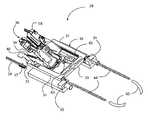
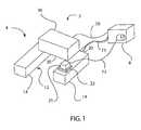
- FIG. 1is a schematic view of a minimally-invasive surgical system.
- FIG. 2is a perspective view of a base of an effector used in the system of FIG. 1 .
- FIG. 3is a bottom view of the base of FIG. 2 .
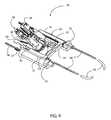
- FIG. 4is a perspective partially-exploded view of a portion of an exemplary effector used in the system of FIG. 1 .
- FIG. 5is a detail view of the distal end of an anvil of FIG. 4 .
- FIG. 6is a top view of a spring utilized in the effector of FIG. 4 .
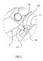
- FIG. 7is a detail perspective view of the connection between the base and a mount of FIG. 4 .
- FIG. 8is an exploded view of the anvil of FIG. 4 and connected structure.
- FIG. 9is a perspective view of an anvil control mechanism optionally utilized in the system of FIG. 1 .
- FIG. 10is a perspective view of an embodiment of a portion of the effector of FIG. 4 .
- FIG. 11is a perspective view of a control unit of the system of FIG. 1 .
- the surgical system 2includes an effector 4 configured to engage tissue.
- the effector 4includes a base 12 that is configured to be attached to tissue, such as by suction, while allowing substantially unrestricted motion of that tissue.
- the tissuemay be heart tissue, such that the base 12 is configured for attachment to the exterior of the heart while allowing the heart to move substantially freely during the duration of that attachment.
- the term “heart”may refer to the heart itself, as well as the heart in combination with one or more layers of tissue that are present on its exterior, such as the epicardium, pericardium, myocardium, coronary arteries and/or fatty tissue.
- the base 12may be at least partially flexible, and/or substantially conformable to the heart.
- the base 12may be composed at least partially of silicone.
- the base 12 shown in FIG. 1is merely exemplary; the base 12 can be shaped in any appropriate manner.
- the base 12may be unitary, have multiple independent components, or have a uniform cross-section or a cross-section that varies over at least a part of the base 12 .
- the base 12may be symmetrical, at least in part, or asymmetrical.
- the effector 4may be detachable from the remainder of the system 2 , such that effectors 4 may be interchanged on the system. This interchangeability allows the system to be used for multiple procedures on the same patient.
- the base 12may include one or more contact elements 14 that are configured to contact tissue, such as heart tissue.
- the contact element or elements 14may form the entire base 12 , or may be connected to a frame and/or other structure (not shown) to form the base 12 . Where multiple contact elements 14 are used, they may be spaced apart from one another, arranged symmetrically about a point or axis, arranged asymmetrically, arranged substantially linearly and/or parallel to one another, or otherwise oriented and/or configured. At least one contact element 14 may be sized and/or shaped differently from at least one other contact element 14 .
- This exemplary base 12includes two contact elements 14 spaced apart from one another.
- the contact elements 14are spaced apart from one another by a distance at least as wide as the maximum width of the average coronary artery.
- the contact elements 14are substantially rectangular, and are substantially the same size and shape as one another.
- the contact elements 14may be shaped in a different manner.
- the contact elements 14may have one or more rounded ends, or may be shaped elliptically, trapezoidally, or in a different way. Further, the contact elements 14 need not be the same size and shape as one another.
- the contact elements 14may be at least partially flexible.
- the contact elements 14may be fabricated from silicone or other flexible biocompatible material.
- the contact elements 14may be fabricated at least in part from rigid biocompatible material such as stainless steel.
- more than two contact elements 14may be used.
- a single contact element 14may be used, with at least two spaced-apart segments. Such a single contact element 14 may have a “U” shape or similar shape.
- the contact elements 14are connected to one another by a bridge 16 .
- the bridge 16may be formed integrally with the contact elements 14 to form a one-piece unitary structure, or may be connected to the contact elements 14 via adhesive, connectors, or any other appropriate structure, mechanism or method.
- the bridge 16allows the contact elements 14 to move relative to one another.
- the bridge 16may be formed from silicone or other flexible biocompatible material, such that it can flex and allow the contact elements 14 to move. This motion allows the contact elements 14 to be placed in substantial contact with the exterior of the heart 10 .
- the bridge 16may be made from stainless steel or other rigid biocompatible material, and connected to at least one contact element 14 by a hinge or other mechanism that allows motion of at least one contact element 14 relative to the bridge 16 and/or at least one other contact element 14 .
- Each contact element 14includes at least one chamber 24 defined therein, and is substantially open on its underside.
- the use of the terms “under,” “underside,” “lower,” and “upper” in this documentdo not limit the orientation in which the effector 4 or other elements of the surgical system 2 may be used, but rather are utilized for convenience and clarity in describing the structure of the surgical system 2 .
- each contact element 14has an underside that is completely open.
- at least one contact element 14may have a lower surface that is partially open.
- the lower surface of at least one contact element 14may be a smooth plane having one or more apertures or holes defined therein.
- the lower surface of at least one contact element 14may be a screen or mesh.
- the contact element 14may have any other suitable configuration of underside or lower surface.
- At least one contact element 14may have more than one chamber 24 defined therein. If so, one or more dividers 28 may separate those chambers 24 from one another. Each divider 28 may extend downward from the upper surface of the corresponding contact element 14 , and may be formed integrally with that contact element 14 . Each divider 28 is oriented substantially longitudinally along the corresponding contact element 14 . Alternately, at least one divider 28 is oriented in a different manner relative to the corresponding contact element 14 . The divider 28 has a zig-zag or sawtooth shape. However, at least one divider 28 may be shaped differently. For example, at least one divider 28 may be substantially linear, or substantially curved. The dividers 28 within different contact elements 14 and/or the same contact element 14 may be shaped and/or oriented differently from one another.
- At least one connector 20is attached to or formed integrally with at least one contact element 14 .
- the connector 20is used to connect the corresponding contact element 14 to a vacuum source.
- the connector 20may be any connector suitable for this purpose.
- the connector 20may be a simple pass-through, threaded or not, suitable for connection to a vacuum hose 71 .
- the connector 20is not used. Instead, a port or aperture is provided in at least one contact element 14 , where vacuum is applied in another manner to that port or aperture. Vacuum may be provided independently to two or more different chambers 24 in the base 12 , thereby providing redundancy in the event that one chamber 24 does not secure to tissue or becomes unsecured from tissue.
- vacuummay be provided independently to two or more different contact elements 14 , providing redundancy in the event that vacuum fails in an entire contact element 14 ; if so, the remaining contact element or elements 14 can still secure to tissue.
- An orifice(not shown) may be provided for each chamber 24 , sized and positioned to restrict flow into and out of that chamber 24 . In this way, any loss of vacuum in one chamber 24 does not substantially propagate back to the vacuum source and result in a loss of vacuum for the other chambers 24 supplied by that vacuum source.
- At least one contact element 14includes a bay (not shown) that is thicker than the remainder of the contact element 14 , where at least one connector 20 is attached to or extends from the bay.
- the bayprovides additional thickness at an area of the contact element 14 , where the connector or connectors 20 that are attached to the bay 20 are large enough to require such additional thickness for adequate mounting to the contact element 14 .
- At least one bayincludes a chamber therein that is connected to at least one chamber 24 in the corresponding contact element 14 by a port 26 defined in a surface of that chamber 24 . That is, vacuum is applied to each chamber 24 by at least one port 26 defined through a surface of that chamber 24 .
- the effector 4may include at least one sensor 21 .
- the sensor 21is oriented such that it has a view of the area of tissue to be surgically treated, which may be referred to as the surgical field.
- the sensor 21may be any type of sensing device, or a component of a larger sensing device.
- the sensor 21may be connected to the base 12 and/or to a different part of the effector 4 , directly or indirectly.
- the sensor 21may be connected to the base 12 and/or other part of the effector 4 , in a detachable or a permanent way.
- the sensor 21is substantially fixed relative to the base 12 .
- the sensor 21may be a type that is configured to detect electromagnetic radiation in the visible light portion of the spectrum, such as an endoscope, a camera, or any other type of imaging sensor.
- the senor 21may be a part or component of an imaging sensor, such as a CCD chip, a lens or lens assembly, fiber optic cables, or other component of an imaging sensor.
- the sensor 21may instead or additionally be of a type configured to detect electromagnetic radiation outside the visible light portion of the spectrum, such as an infrared sensor, an ultraviolet sensor or other sensor.
- An infrared sensormay be useful in detecting the precise location of a coronary artery and/or of a blockage in a coronary artery, because blood flow through the coronary artery and blockage of the coronary artery typically have different temperatures from one another and from surrounding tissue.
- any other sensor that is useful in detecting contrast between a blocked area and an unblocked area of a coronary artery, or between a coronary artery and the remainder of the heartmay be used.
- the sensor 21itself, or a separate emitter (not shown) emits energy that is modulated or otherwise altered by its interaction with tissue, and the modulated or altered energy is sensed by the sensor 21 .
- a sensor 21may be an ultrasound array that emits ultrasonic energy and detects the ultrasonic energy that is reflected from tissue.
- More than one sensor 21may be connected to the base 12 , if desired.
- an endoscope and an infrared sensor bothmay be connected to the base 12 .
- Sensor datais transmitted from each sensor 21 to a display or similar device that is viewable by the surgeon.
- This sensor datamay be handled in any suitable manner.
- a display 11may be included in a control unit 8 connected to the sensor 21 , as described in greater detail below.
- the connection between each sensor and the display 11may be made through a wire 73 , or through a wireless connection.
- Standard componentssuch as video interface cards, switches, and/or other equipment may be provided between the sensor 21 and the display 11 , as is standard in the art.
- eachmay be connected to the same display 11 , and the sensor output may be shown on that display with a split screen, by switching between inputs, or in any other manner.
- control unit 8includes output connectors (not shown) that are connectable to a monitor, an information handling system, or other device. If so, the control unit 8 need not include the display 11 ; rather, sensor data can be passed through the control unit 8 to a monitor of the user's choice; in this way, the control unit 8 can be made smaller and less complex.
- the control unit 8may contain at least one display 11 and at least one set of output connectors.
- the control unit 8includes a wireless transmitter that is configured to transmit sensor data from the control unit 8 to another device, such as a monitor or an information handling system. Alternately, sensor data is transmitted directly from the sensor 21 to a display that is unconnected to the control unit, such as by one or more cables or by wireless transmission.
- the effector 4includes a sensor mount 22 to which at least one corresponding sensor 21 is connected.
- the sensor mount 22is oriented in a direction that provides the corresponding sensor or sensors 21 with a view of the surgical field, as described in greater detail below.
- the sensor mount 22is fixed to the base 12 .
- Each sensor 21may be connected to the corresponding sensor mount 22 in a detachable or a permanent way.
- the sensor mount 22is shaped in any appropriate manner to hold a sensor 21 substantially fixed relative to the base 12 . Further, the connection between the sensor mount 22 and the corresponding sensor 23 may be accomplished by any appropriate structure, mechanism or method.
- the sensor mount 22may be a tubular element configured to hold at least a portion of that cylindrical body via a friction fit or other fit.
- the sensor 21may screw into threads provided on the sensor mount 22 .
- the sensor 21may be fixed to the sensor mount 22 with adhesive.
- the sensor 21may be welded or otherwise permanently fixed to the sensor mount 22 .
- the base 12is configured to contact tissue, such as by one or more contact elements 14 .
- the contact elements 14 and/or other components of the base 12are substantially secured to the tissue that they contact, while allowing that tissue to move. That is, the base 12 is connected to and rides on the surface of moving tissue, without substantially restricting the motion of that tissue.
- the contact elements 14 of the base 12may be secured to the exterior of the heart, while allowing the heart to beat substantially normally.
- the effector 4includes a tool 36 that is connected to the base 12 .
- the tool 36may be connected to the base 12 directly, or indirectly via a mount 30 .
- the mount 30may be any structure or mechanism that is appropriate for holding and/or moving the tool 36 relative to a remainder of the effector 4 .
- the tool 36is a surgical structure or mechanism that is configured to interact with the tissue to which the base 12 may be connected, or other tissue.
- the tool 36is movable relative to the base 12 in at least one degree of freedom.
- the tool 36may be rigidly connected to the base 12 , or may be formed along with the base 12 as a single, integral unit.
- the tool 36may be connected to the control unit 8 , such as by one or more cables 70 .
- the tool 36may be connected to the control unit 8 indirectly, such as through a cable extending between the base 12 and the control unit 8 .
- the tool 36is operationally connected to the control unit 8 via standard wireless communication hardware and protocols.
- at least one sensor 21may be connected to the tool 36 , instead of or in addition to being connected to the base 21 .
- the effector 4 as a wholeis connected to the control unit 8 non-rigidly. That is, the mechanism or mechanisms, or structure or structures, between the effector 4 and the control unit 8 are non-rigid. Such mechanisms and structures may include cables, hoses, flexible tubes and/or other flexible entities. Thus, the effector 4 is not rigidly connected to any portion of the body of the patient. Because the effector 4 is connected to the control unit 8 non-rigidly, the connection between the effector 4 and the control unit 8 substantially does not restrict any moving tissue to which the effector 4 may be attached. As a result, the effector 4 does not immobilize moving tissue to which it is attached.
- the control unit 8may be used to position and operate the effector 4 .
- the control unitmay include a joystick, handle, dial, lever, switch, trigger, console, information handling system such as a computer, a combination of one or more of those mechanisms, or any other appropriate structure, mechanism or combination thereof.
- the control unit 8may control the effector 4 mechanically, such as via cables or other force transmission members; electrically and/or via software commands, such as via analog signals or digital commands transmitted to stepper motors or other actuators; by a combination of mechanical and/or electrical devices, and/or software commands, or by another or additional type of mechanism and/or structure.
- the tool 36may be steerable relative to the base 12 . That is, the orientation of the tool 36 relative to the base 12 may be controlled, such as via the control unit 8 . Further, the position of the tool 36 on the base 12 may be controllable as well, such as via the control unit 8 . Thus, the tool 36 may be steered remotely via the control unit 8 . A surgeon may utilize the image data or other data transmitted from the sensor 21 to the display 11 to steer the tool 36 within the surgical field such that it engages tissue more effectively for surgical intervention.
- the tool 36may be an anastomosis tool. That is, the tool 36 may be configured to connect a graft vessel to a target vessel, such as by deploying a plurality of staples, clips or other independent connectors, or a unitary anastomosis device.
- the anastomosis toolmay include an anvil, a delivery mechanism for a unitary connector, a delivery mechanism for a number of separate and independent connectors, and/or any other appropriate mechanism. Further, the anastomosis tool may be configured to perform an arteriotomy on the target vessel before or after deployment of an anastomosis connector or connectors.
- the effector 4 of FIG. 4is configured to perform anastomosis, such as a CABG procedure, on moving tissue such as a beating heart 10 .
- a beating heart 10may refer to the heart itself, as well as the heart in combination with one or more layers of tissue that are present on its exterior, such as the epicardium, pericardium, and/or fatty tissue.
- the control unit 8is located outside of the body of the patient, and the interface extends through a port (not shown) in the chest of the patient.
- the control unit 8is connected to the effector 4 via one or more force and/or information transmission mechanisms, which are described in greater detail below.
- the base 12is substantially as described above.
- a tool 36is connected to the base 12 , where the tool 36 is an anastomosis tool 36 .
- the anastomosis tool 36may be any appropriate mechanism for deploying one or more anastomosis devices.
- the anastomosis tool 36may deploy a unitary anastomosis device, one or more clips, one or more staples, a combination thereof, or a different type of anastomosis device.
- the anastomosis tool 36is a suturing mechanism or an assisted suturing mechanism.
- the anastomosis tool 36may be as described in U.S. patent application Ser. No.
- anastomosis tool 36may be utilized, if desired.
- the anastomosis tool 36may be configured to hold and deploy at least one staple to connect a graft vessel to a target vessel.
- the staple or staplesmay be as described in U.S. patent application Ser. No. 10/309,519 filed on Dec. 4, 2002, “Anastomosis Staple,” which is hereby incorporated by reference in its entirety.
- the anastomosis tool 36may be configured to deploy one or more clips to connect a graft vessel to a target vessel.
- such clipsmay be as described in U.S. Pat. No. 6,193,734 to Bolduc et. al.
- such clipsmay be as described in U.S. Pat. No. 6,503,260 to Schaller et. al.
- the anastomosis toolmay be configured to deploy a unitary anastomosis device to connect a graft vessel to a target vessel.
- a unitary anastomosis devicemay be as described in U.S. patent application Ser. No.
- such a unitary anastomosis devicemay be as described in U.S. Pat. No. 5,695,504 to Gifford III et. al.
- such a unitary anastomosis devicemay be as described in U.S. Pat. No. 6,152,937 to Peterson et. al.
- such a unitary anastomosis devicemay be as described in U.S. Pat. No. 6,113,612 to Swanson et. al.
- such a unitary anastomosis devicemay be as described in U.S.
- such a unitary anastomosis devicemay be as described in International Publication No. 00/56228 of Loshakove et. al.
- such a unitary anastomosis devicemay be as described in U.S. Pat. No. 6,251,116 to Shennib et. al.
- such a unitary anastomosis devicemay be the Symmetry device of St. Jude Medical or the CorLink device of Johnson & Johnson.
- the anastomosis toolmay be configured to deploy a multi-piece anastomosis device to connect a graft vessel to a target vessel.
- such a multi-piece anastomosis devicemay be as described in U.S. Pat. No. 6,352,543 to Cole.
- such a multi-piece anastomosis devicemay be as described in U.S. Patent Application Publication No. 2003/0023252 of Whayne.
- such a multi-piece anastomosis devicemay be as described in International Publication No. 02/30172 of Loshakove et. al.
- anastomosis tool 36is substantially as disclosed in U.S. patent application Ser. No. 10/392,336, “System for Performing Anastomosis.”
- Such an anastomosis tool 36includes an anvil 38 configured to penetrate the wall of a target vessel, such as a coronary artery.
- a cutter 40is movable relative to the anvil 38 .
- the cutter 40translates along a channel 64 in the anvil 38 .
- the cutter 40includes a first incising element 66 at its distal end, and a second incising element 68 on its upper surface.
- the direction substantially perpendicular to the longitudinal centerline of the anvil 38 toward the wall of the target vesselmay be referred to as “upward”, and the direction substantially perpendicular to the longitudinal centerline of the anvil 38 away from the wall of the target vessel may be referred to as “downward”.
- the positioning of the anvil 38 in useis not limited to an orientation in which these directions correspond to absolute directions measured relative to the ground.
- the second incising element 68may be spaced apart from and proximal to the first incising element 66 .
- the second incising element 68includes a proximally-facing cutting edge (not shown) to facilitate the creation of an arteriotomy in the wall of the target vessel.
- the anvil 38may include an opening 48 at its distal end through which the first incising element 66 extends initially, in order to penetrate the wall of the target vessel.
- the anvil 38includes an upper opening 76 in its upper surface 78 through which the second incising element 68 can be moved to create an arteriotomy in the wall of the target vessel.
- the distal portion of the anvil 38includes an anvil arm 39 for insertion into the lumen of the target vessel.
- the cross-sectional area of the anvil arm 39is small enough such that withdrawal of the anvil arm 39 from the wall of the target vessel substantially does not result in leakage through that wall.
- the distal tip of the anvil arm 39may be sharp in order to facilitate penetration of the wall of the target vessel.
- the cutter 40has a sharp distal end 46
- the distal end of the anvil 39has an aperture 41 therein that allows the distal end 46 of the cutter 40 to protrude outward through the aperture 41 and penetrate the wall of the target vessel.
- a stop 92is located on the anvil 38 , at the proximal end of the anvil arm 39 .
- the stop 92extends upward from the anvil 38 to increase its cross-sectional area, such that the anvil arm 39 substantially cannot penetrate the wall of the target vessel any further than the position defined by the stop 92 .
- the stop 92is substantially blunt, such that its contact with the wall of the target vessel is substantially atraumatic and substantially does not increase the size of the incision made in the wall of the target vessel by the anvil arm 39 .
- the anvil 38includes a widened segment 56 at its proximal end, which is wider than the anvil arm 39 .
- the widened segment 56is no wider than the anvil arm 39 .
- the widened segment 56may be open along at least a portion of its length.
- a driver 48is configured to be positioned at least partly within the widened segment 56 .
- the driver 48is held at least partly within a guide 50 that also is located at least partly within the widened segment 56 .
- the driver 48is a threaded rod or screw; where the guide 50 is used, that guide 50 is threaded to match.
- the driver 48is unthreaded, and is configured to be urged relative to the anvil 38 under the influence of compressed gas or vacuum, or by a different force.
- the driver 48may be made of any appropriate material.
- a drive shaft 52is connected to the proximal end of the driver 48 .
- the drive shaft 52may be a thin-walled tube formed of polyetheretherketone (PEEK) plastic or other suitable material, which is connected at one end to a portion of the proximal end of the driver 48 and at the other end to the control unit 8 .
- PEEKpolyetheretherketone
- the drive shaft 52rotates, it causes the threaded driver 48 to rotate as well. This rotation of the threaded driver 48 advances it relative to the correspondingly-threaded guide 50 .
- the drive shaft 52is a tube that transmits compressed gas or vacuum to the driver 48 .
- the drive shaft 52transmits force to the driver 48 in a different way.
- An interface 47is connected to or formed into the cutter 40 at its proximal end. Alternately, the interface 47 is positioned at a different location on the cutter 40 .
- the interface 47is shown connected to the upper portion of the proximal end of the cutter 40 , but could be located to the lower portion or on either side of the proximal end of the cutter 40 instead.
- the interface 47is configured to engage the driver 48 .
- the driver 48may be a threaded rod or screw, and the interface 47 includes a correspondingly-threaded opening therein. The opening may extend completely through the interface 47 .
- both the driver 48 and the interface 47are unthreaded, and the driver 48 is urged relative to the interface 47 under the influence of compressed gas or vacuum, or by a different force. Both the interface 47 and the driver 48 may be made of any appropriate material.
- the cutter 40may be biased downward, such as by a spring 58 held in place by a bracket 62 .
- the spring 58may be connected to the bracket 62 .
- the spring 58is configured to exert a downward force on the cutter 40 . That is, the spring 58 is in compression, such that it biases the cutter 40 downward. This biasing is performed during substantially all of the travel of the cutter 40 . Alternately, the cutter 40 is only biased downward during a portion of the travel of the cutter 40 . Alternately, the cutter 40 may be biased upward.
- the anastomosis tool 36also includes a staple holder 18 .
- the staple holder 18is moveable relative to the anvil 38 , between an open position and a closed position.
- the staple holder 18is configured to hold staples (not shown).
- the staplesare substantially as disclosed in U.S. patent application Ser. No. 10/309,519 filed on Dec. 4, 2002, “Anastomosis Staple.”
- the staple holder 18is operationally connected to the control unit 8 non-rigidly, such as by a cable 70 .
- the anastomosis tool 36is connected to a mount 30 to form an assembly 28 .
- the mount 30may include two spaced-apart members 31 connected at their proximal ends to a cross member 33 , forming an open-ended configuration.
- the cross member 33may be at a substantially right angle to at least one of the members 31 , or may be oriented at a different angle to at least one of the members 31 .
- the mount 30may be a unitary structure, wherein the members 31 and cross member 33 form an integral unit.
- the members 31 and the cross member 33all lie in substantially the same plane. Alternately, the members 31 and the cross member 33 do not all lie in substantially the same plane.
- the mount 30may be constructed from stainless steel or other suitable biocompatible material or materials.
- the interface structure 32is a leaf spring, advantageously is composed of nickel-titanium alloy or other superelastic alloy, at least in part. Alternately, the interface structure 32 is constructed from stainless steel or other suitable biocompatible material having an appropriate spring constant.
- the interface structure 32includes two arms 96 . Alternately, the interface structure 32 includes one arm 96 , or more than two arms 96 . A proximal segment 102 of the leaf spring 32 connects the arms 96 to one another.
- the leaf spring 32is unitary, with the arms 96 and the proximal segment 102 being components thereof.
- a tab 98extends proximally from the proximal segment 102 , at approximately the center of the proximal segment 102 .
- the tab 98may be positioned differently relative to the proximal segment 102 , if desired.
- at least one tongue 100may extend distally from the proximal segment 102 of the interface structure 32 .
- the tongue or tongues 100may engage the staple holder 18 (not shown) and bias it to an open position relative to the anvil 38 .
- the tongue or tongues 100 of the leaf spring 32may be connected in any appropriate manner to the anastomosis tool 36 , such as by welding, adhesive, connectors, or any other or additional structure, mechanism or method. Alternately, the anastomosis tool 36 is connected also, or instead, to a different part of the leaf spring 32 .
- At least one arm 96 of the interface structure 32has a distal end 94 that is oriented substantially laterally and connected to a corresponding slider 34 .
- the connection between the distal end 94 of an arm 96 and the slider 34may be accomplished with any appropriate structure, mechanism or method.
- the distal end 94 of an arm 96may be pressure-fit into a slot (not shown) on a side of the corresponding slider 34 ; welded to the corresponding slider 34 ; attached with adhesive to the corresponding slider 34 , or otherwise connected thereto.
- a different part of each arm 96is connected to a corresponding slider 34 , or the distal end 94 of at least one arm 96 is configured differently and attached to the corresponding slider 34 .
- An actuator 44may extend into each passage 35 within the mount 30 .
- Each actuator 44may be connected to the corresponding slider 34 , directly or operatively, in any appropriate manner.
- Each actuator 44may be any suitable mechanism or structure for transmitting force.
- each actuator 44may be a threaded drive screw.
- a portion of each slider 34may include a threaded surface 37 .
- a portion of the surface of at least one passage 35instead, or additionally, may include a threaded surface.
- Each threaded surface 37is shaped and threaded to match the size, shape and threading of the corresponding actuator 44 . Rotation of the actuator 44 causes the corresponding slider 34 to move proximally or distally, depending on the direction of rotation of the actuator 44 .
- This motionmay be caused by direct engagement between the actuator 44 and a threaded surface 37 of the corresponding slider 34 .
- the distal end of the actuator 44may press the corresponding slider 34 distally as the actuator 44 advances.
- a flexible drive shaft 45is connected to the proximal end of each actuator 44 .
- at least one drive shaft 45may be a thin-walled tube formed of PEEK plastic or other suitable material, which is connected at one end to a portion of the proximal end of the corresponding actuator 44 and at the other end to the control unit 8 .
- the drive shaft 45rotates, it causes the corresponding threaded actuator 44 to rotate as well. This rotation of the threaded actuator 44 advances it relative to the correspondingly-threaded passage 35 in the corresponding member 31 .
- the drive shaft 45is a tube that transmits compressed gas or vacuum to the actuator 44 .
- the drive shaft 45transmits force to the actuator 44 in a different way.
- a single drive shaft 45engages all of the actuators 44 , such as by a gear assembly (not shown).
- a ledge 43extends distally from the cross member 33 of the mount 30 .
- the ledge 43may be formed into the cross member 33 , or connected to the cross member 33 , such as by welding, adhesive, one or more fasteners, or any other appropriate structure, mechanism or method.
- a bracket 42may include the ledge 43 , where the bracket 42 is attached to the cross member 33 .
- the mount 30may be connected to the base 12 in any appropriate manner. Referring to FIG. 7 , an exemplary connection between the mount 30 and the base 12 is shown. Three posts 102 extend downward from the mount 30 . A ball 104 is formed into or connected to the bottom of each post 102 . A receiver 106 corresponds to each post 102 , and is configured to receive the ball 104 of the corresponding post 102 . Each receiver 106 is connected to the base, such as by adhesive, welding, one or more fasteners, or any other appropriate mechanism, structure or method.
- Each ball 104is free to rotate relative to the corresponding receiver 106 .
- each post 102is free to pivot relative to the corresponding receiver 106 , limited by contact between the post 102 and the opening 108 at the top of the receiver 106 through which the post 102 extends.
- the three balls 104define a plane, relative to which the base 12 can curve. Alternately, more or fewer than three balls 104 and posts 102 are utilized. Alternately, the posts 102 extend, upward from the base 12 , and the receivers 106 are connected to the mount 30 .
- the mount 30is instead connected to the base 12 via a stage (not shown) or other mechanism that is movable relative to the base 12 .
- the stagemay be configured to move with one or more degrees of freedom relative to the base 12 to provide more controllability of the orientation of the mount 30 relative to the base 12 .
- the mount 30is rigidly connected to the base 12 .
- anvil control 112is shown.
- the anvil control 112may be a part of the control unit 8 , or may be separate from the control unit 8 .
- the anvil control 112includes a base 114 from which a pylon 116 extends substantially upward.
- the base 114may be substantially disc-shaped, and the pylon 116 may be substantially cylindrical.
- the base 114 and/or pylon 116may be shaped differently.
- the pylon 116is substantially centered on the base 114 , but may be positioned differently relative to the base 114 .
- the base 114is not a separate component, but instead is a portion of the control unit 8 .
- a pedestal 118is connected to the top of the pylon 116 in such a manner that it can bend relative to the longitudinal centerline of the pylori 116 .
- the pedestal 118may be connected to the pylon 116 via a flexible shaft 120 .
- the pedestal 118may be gimbaled relative to the pylon 116 .
- the pedestal 118may include one or more notches 122 along its perimeter.
- a joystick 124is connected to the pedestal 118 , such as through a joystick base 126 .
- the joystick base 126may be positioned immediately adjacent to the pedestal 118 , or spaced apart from the pedestal 118 and connected thereto via a post or other intermediate structure.
- the joystick 124is connected to the pedestal 118 in such a way that the joystick 124 and the pylon 116 substantially share a longitudinal centerline. Alternately, the joystick 124 may be offset from the pylon 116 .
- the joystick base 126may include one or more notches 128 along its perimeter.
- a shell 130shown in FIG. 9 with phantom lines, is cylindrical, with a cavity at its center. The shell 130 is connected to the base 114 such that the pylon 116 extends into the cavity of the shell 130 .
- the shell 130includes one or more passages 132 longitudinally therethrough, extending substantially parallel to the longitudinal centerline of the pylon 116 . Alternately, the passages 132 are oriented differently. Alternately, the shell 130 is configured differently.
- At least one cable 134extends through each passage 132 in the shell.
- Each cable 134may be made of stainless steel or any other appropriate material.
- Each cable 134is connected to the joystick 124 directly or indirectly. For example, each cable 134 extends through the corresponding passage 132 , out of the proximal end of the passage 132 , then radially toward the joystick base 126 . At the joystick base 126 , each cable 134 then passes through a notch 128 therein, which is narrow enough to hold the cable 134 firmly therein. Each cable 134 then extends distally through a notch 122 in the pedestal 118 , and is anchored to the pedestal 118 by any appropriate structure, mechanism or method.
- a bead(not shown) or similar structure may be fixed to the cable 134 , where the bead is larger than the notch 122 in the pedestal 118 , such that the bead cannot be pulled through the notch 122 .
- each cable 134may be fixed to the pedestal, such as by welding, soldering or adhesive. Any other structure, mechanism or method may be used to connect each cable 134 to the pedestal 118 .
- the anvil control 112is part of the control unit 8 or otherwise configured such that it is spaced apart from the effector 4 .
- Each cable 134extends from the anvil control 112 to the effector 4 .
- the anvil 38is connected to a bracket 136 , which in turn is connected to the interface mechanism 32 .
- An interface ring 138is connected to the bracket 136 by a ball joint 140 , and the anvil 38 is connected to the interface ring 138 .
- the interface ring 138may be shaped differently, if desired.
- the interface ring 138includes one or more apertures 142 therein, where the number of apertures 142 is equal to the number of cables 134 .
- Each cable 134passes through the corresponding aperture 142 and is then anchored to the interface ring 142 by any appropriate structure, mechanism or method. Alternately, the apertures 142 are not used, and the cables 134 are connected to the interface ring 138 differently. Alternately, the numbers of apertures 142 and cables 134 may be different.
- the apertures 142are advantageously spaced substantially evenly about the interface ring 138 .
- the notches 128are spaced substantially evenly about the joystick base 126 , in a similar manner to the spacing of the apertures 142 about the interface ring 138 .
- the cables 134 connected to the joystick base 126are selectively tensioned and loosened. This tensioning and loosening of selected cables 134 transmits force to the interface ring 138 .
- This forcemoves the interface ring 138 , and thus moves the anvil 38 to a position analogous to that of the joystick 124 .
- the anvil 38is steerable by the anvil control 112 .
- the staple holder 37may be connected to the anvil 38 , or may be separated completely from the anvil 38 .
- control unit 8is shown.
- the control unit 8 described hereis mechanical.
- the control unit 8may control the effector 4 via electromechanical actuation, by hardware and/or software control of motors and/or other components, by controlling the pressure and flow of a fluid such as carbon dioxide gas, by a combination of these methods, or by a different method.
- the control unit 8may include more, fewer or different controls than described below, where those controls may be configured to perform functions other than those described below.
- the knobs described belowmay be any other appropriate control mechanisms.
- the control unit 8includes a first knob 144 operationally connected to the effector 4 via a cable 70 .
- the first knob 144is configured to close the anastomosis tool 36 after the anvil 38 has entered the lumen of a target vessel.
- the anastomosis tool 36may be closed by applying tension to a cable 70 , where that cable 70 is routed through the anastomosis tool 36 in such a manner that the tension causes the anastomosis tool 36 to close.
- the control unit 8also includes a second knob 146 operationally connected to the effector 4 via the drive shaft 52 , which extends from the effector 4 to the control unit 8 .
- the second knob 146is configured to rotate the drive shaft 52 as the second knob 146 is rotated, thereby causing the retraction of the cutter 40 after the anvil 38 has entered the lumen of the target vessel.
- the control unit 8includes a third knob 148 that is operationally connected to the effector 4 via a cable 70 .
- the third knob 148is configured to deploy connectors from the staple holder 18 after the anastomosis tool 36 has been closed. The connectors may be deployed by applying tension to a cable 70 , where that cable 70 is routed into the anastomosis tool in such a manner that the tension causes connectors to deploy.
- the control unit 8includes a fourth knob 150 that is operationally connected to the effector 4 via a drive shaft 52 , which extends from the effector 4 to the control unit. The fourth knob 150 is configured to advance the interface mechanism 32 for insertion of the anvil 38 into a target vessel.
- the fourth knob 150does so by rotating the drive shaft or shafts 45 , which in turn advances the drive screws 44 as described above.
- the control unit 8also includes one or more switches 152 configured to control the vacuum applied to the base 12 .
- One or more vacuum hoses 71extend from the control unit 8 to the base 12 , and the switches 152 are configured to apply vacuum to the base 12 when they are in the open position.
- the switches 152may have multiple toggle positions, or may be dials or other controls, such that the amount of vacuum applied can be controlled.
- the control unit 8itself is connected to a vacuum source, such as a vacuum connector provided at a hospital operating room, or a vacuum tank, such that the control unit 8 is able to provide vacuum through the one or more vacuum hoses 71 .
- the control unit 8also includes a joystick 112 , configured substantially as described above.
- a sheath(not shown) or other structure may collect one or more cables, drive tubes, vacuum hoses and/or wires extending between the effector 4 and the control unit 8 , in order to prevent external interference with them, ease insertion through the port in the patient, facilitate the surgical procedure, and improve the aesthetics of the surgical system 2 .
- the sheathit may be a flexible tube having one or more lumens extending therethrough, wherein each lumen is configured to receive one or more items extending between the effector 4 and the control unit 8 .
- the surgical system 2may be used to perform a CABG procedure on a stopped heart instead. Further, the surgical system 2 can be used to perform surgical procedures on other organs, and is not limited to the performance of anastomosis, much less a CABG procedure.
- the sequence of events in the example belowis purely exemplary, and may be varied at the discretion of the surgeon.
- the use of the surgical system 2does not require delivery of any medical device or tool to the surgical site by a catheter-based delivery system or instrument. That is, no femoral access is required for the use of the surgical system 2 .
- a catheter-based delivery system or instrumentmay be used in conjunction with the surgical system 2 if desired.
- At least one incisionis made in the chest of a patient between two adjacent ribs, such that an intercostal approach to the heart may be taken.
- This incisionmay be referred to as a port.
- at least one incisionis made at a different location on the patient.
- at least one incisionmay be made below the rib cage of the patient, such that a sub-xyphoid approach to the heart may be taken.
- only a single incisionis made in the patient, because a separate incision is not needed for an endoscope or other sensor to be inserted into the patient; rather, the sensor 21 is attached to the effector 4 which will be inserted through the single incision.
- the surgeonthen makes an incision in the pericardium.
- the tools and procedures for such an incisionare standard.
- the patientthen may be oriented appropriately for the intended anastomosis site. Such orientation may include rolling the patient onto his or her side for better access to the heart. By doing so, the heart naturally moves partially through the incision in the pericardium, facilitating access. For example, if the anastomosis is to be performed on the left side of the heart, the patient may be rolled onto his or her right side; if the anastomosis is to be performed on the right side or back of the heart, the patient may be rolled onto his or her left side.
- a measurement deviceis then inserted through the incision and utilized to measure a graft length between the aorta or other source vessel and the coronary artery having a blockage to be bypassed, while the heart is beating.
- the measurement devicemay be a clip that is temporarily attached to the aorta, with a flexible tail attached thereto that is moved to the coronary artery to determine the distance that will be traversed by a graft vessel.
- Such a measurement devicemay be substantially as described in U.S. patent application Ser. No. 10/041,542, filed on Jan. 7, 2002, which is hereby incorporated by reference in its entirety. Any other measurement device may be utilized, if desired.
- the surgeonneed not physically measure the graft length at all, and instead estimates the length using X-rays, angiograms, visual inspection of the chest cavity, and his or her judgment and experience.
- the coronary artery that is treated with the surgical system 2may be the left anterior descending (LAD) artery or any other coronary artery that can be reached through the approach chosen by the surgeon.
- LADleft anterior descending
- a graft vesselis harvested from the patient.
- the graft vesselmay be a saphenous vein, radial artery, or any other appropriate graft vessel.
- the selection and harvest of a graft vesselis well-known to those skill in the art.
- the graft vesselis then cut to the graft length determined above.
- a graft vesselis not harvested at all. Rather, a mammary artery is taken down, meaning that one end of a mammary artery is cut and clamped, and the other end of the mammary artery is left in place.
- the use of the mammary arterysimplifies the CABG procedure, because the graft vessel only needs to be connected to the coronary artery, rather than to the coronary artery and the aorta or other source of blood.
- the graft vesselis then prepared for anastomosis. This preparation may take place inside the chest cavity, outside the chest cavity, or both. As an example of preparation, one or more flaps are incised in an end of the graft vessel, and those flaps are then connected to the staple holder 18 .
- the connection between the graft vessel and the staple holder 18is substantially as described in U.S. patent application Ser. No. 10/392,336.
- the graft vesselmay be prepared for anastomosis in any other appropriate way, if desired.
- the other end of the graft vesselalso can be prepared for anastomosis to the aorta or other blood source.
- One of the lungs of the patientmay then be deflated, if it has not been deflated already. By deflating one of the lungs, additional working space within the chest cavity is created.
- the choice of lung for deflationdepends on the side of the heart on which the anastomosis is to be performed. For example, where the anastomosis is to be performed on the left side of the heart, the left lung is deflated. Where the anastomosis is to be performed on the right side of the heart, the right lung is deflated.
- the surface of the deflated lungmay be used as a working surface. That is, a portion of the graft vessel, or the effector 4 or one or more tools used to prepare the graft vessel and/or connect it to a target vessel, may be rested temporarily on the surface of the lung during the CABG procedure.
- a protective elementsuch as a plastic sheet may be placed between the deflated lung and any items rested on the lung.
- a parameter indicative of pressure in at least one lungmay be sensed and utilized to control inflation of at least one lung.
- at least one pressure sensormay be located in a portion of a bifurcated tube (not shown) introduced into the bronchial passages of the patient.
- two separate tubesare utilized, one for each bronchial passage; if so, two separate pressure sensors may be used, one for each tube.
- the pressure sensormay be connected to the control unit 8 via a wire, a wireless connection, or other structure, mechanism or method.
- the pressure sensoris connected to a mechanism or monitoring device other than the control unit 8 .
- the surgeon or anesthesiologistcan react to this change and change the ventilation of the patient to prevent over- or under-inflation.
- the connection between the pressure sensor and the control unit 8 or other mechanism or monitoring devicemay allow for an automated change of the ventilation of the patient, if desired. As a result, unexpected motion of the lung and/or heart can be reduced or eliminated.
- the epicardiumis dissected at the intended anastomosis site, through the incision in the patient.
- Such dissectionis performed in approximately 30% of all CABG patients, due to the amount of fatty tissue or other tissue present on the exterior of the heart at the anastomosis site.
- the epicardial dissection procedureis well-known to those skilled in the art.
- Such dissectionmay be performed manually, or with a dissection tool (not shown) that is included in the effector 4 .
- a second effector 4is provided, where the tool 36 is a dissection tool. That effector 4 is placed on the heart and actuated in a similar manner to that described below for the actuation of the anastomosis tool 36 .
- the effector 4is inserted through the incision in the patient. This insertion may be performed by hand, with a forceps, or with any other appropriate tool or in any other appropriate way.
- the base 12 of the effector 4is placed in contact with the exterior of the heart.
- the surgeonpositions the effector 4 in proximity to a coronary artery, and in proximity to the location where the anastomosis between the graft vessel and the coronary artery is to be performed.
- the coronary arteryis referred to as the target vessel with regard to anastomosis.
- the base 12is connected to and rides on the exterior of the beating heart, without substantially restricting the motion of the beating heart. That is, the connection of the base 12 to the exterior of the heart is such that the motion of the heart is substantially unrestricted by the base 12 . Further, the shape of the heart and the rate and volume of blood flow through the heart are substantially unaffected by the connection of the base 12 to the exterior of the heart.
- the patientis stationary on a substantially fixed operating table, gurney or similar structure or mechanism; the base 12 is free to move relative to that operating table or other structure.
- the base 12moves along with that tissue.
- the sensor 21is substantially fixed relative to the base 12 , regardless of whether the sensor 21 is connected directly to the base 12 or whether the sensor mount 22 is used. Because the sensor 21 is substantially fixed relative to the base 12 , the sensor 21 also moves along with that tissue. Thus, as the tissue moves and the base 12 and sensor 21 move along with it, the sensor 21 maintains a substantially fixed distance from the tissue, and a substantially fixed orientation relative to that tissue. As a result, the view of the surgical field from the sensor 21 remains substantially steady and motionless.
- the visible image of the surgical fieldremains substantially steady. That is, by substantially fixing the distance between the sensor 21 and moving tissue such as the exterior of the heart, and by placing the base 12 on a specific location on the moving tissue in such a manner as allows the tissue to move freely, virtual stabilization of the image data obtained by that sensor is obtained without the need to resort to expensive and complex computer-based or mechanical motion compensation. Further, the moving tissue need not be immobilized to obtain virtual stabilization.
- Positioning the effector 4 relative to the coronary arterymay be performed in any appropriate manner. As one example, the surgeon first coarsely positions the effector 4 relative to the coronary artery, then finely positions the effector 4 relative to the coronary artery. Coarse positioning refers to gross positioning of the effector 4 relative to the coronary artery, and fine positioning refers to detailed positioning of the anastomosis tool 36 relative to the coronary artery. At the end of the coarse positioning, the contact elements 14 may straddle the coronary artery to be acted upon by the effector. Vacuum may be applied to the exterior of the heart through the base 12 before coarse positioning, or between coarse positioning and fine positioning.
- the surgeonmoves the effector 4 with forceps along the exterior of the heart.
- the surgeonthen actuates one or both of the switches 152 on the control unit 8 , thereby applying vacuum to the exterior of the heart via the base 12 .
- one or both of the switches 152are actuated before the effector 4 is placed on the exterior of the heart, and the amount of vacuum applied through the base 12 is controlled to a first level.
- the base 12can be moved or slid along the exterior of the heart, while still being held to the exterior of the heart.
- the base 12is moved to the desired position, in which the contact elements 14 straddle the coronary artery, in proximity to the anastomosis site.
- the amount of vacuum applied through the base 12is controlled to a second level, which is greater than the first level.
- the base 12is then securely affixed to the exterior of the heart.
- the surgeonmay use the display 11 to view the exterior of the heart via the sensor 21 and determine whether the base 12 is in the desired position relative to the coronary artery.
- the displayrather than a direct view of the anastomosis site, the incision in the patient may be made as small as possible; it does not need to be large enough to allow visual observation of the anastomosis site.
- the surgeonalso uses the display 11 to perform fine positioning of the anastomosis tool 36 .
- the anvil 38is steerable relative to the remainder of the effector 4 , as described above.
- the surgeonviews the surgical field on the display 11 and moves the joystick 112 to steer the anvil 38 to a position in which it is substantially parallel to a portion of the coronary artery.
- the surgeonthen releases the joystick 112 , leaving the anvil 38 in place.
- a lock or clamp(not shown) is actuated from the control unit 8 , locking the cables 134 into place and providing positive confirmation that the anvil 38 will not move relative to the mount 30 after it has been finely positioned.
- the coarse and fine positioning described aboveis merely exemplary. Such positioning could be performed in a different way.
- a coarse positioning mechanism and a fine positioning mechanismmay be provided, where those mechanisms are connected to one another in series or in parallel.
- a coarse positioning mechanism and a fine positioning mechanismmay be provided independently from one another.
- coarse and fine positioningare combined into a single step and/or a single mechanism for positioning the anastomosis tool.
- the anvilis positioned close to and oriented substantially parallel to a portion of the coronary artery. Further, the effector 4 is moving along with the motion of the heart.
- the anastomosis procedurecan begin.
- the surgeonactuates the fourth knob 150 , thereby actuating the drive screws 44 and urging them distally.
- this motion of the drive screws 44urges the interface mechanism 32 distally, such as by interacting with threads on corresponding sliders 34 .
- the tab 98 of the interface mechanism 32initially is in contact with the ledge 43 of the mount 30 .
- the interface mechanism 32is a spring, it is in compression initially; the contact between the tab 98 and the ledge 43 prevents the interface mechanism 32 from moving downward.
- the tab 98moves out of contact with the ledge 43 . At that time, the interface mechanism 32 is released from compression and moves downward and distally.
- the motion of the interface mechanism 32is controlled by selecting its shape and the amount of compression applied to it. Motion of the interface mechanism impels the distal end of the anvil 38 through the wall of the coronary artery and into the lumen of the coronary artery.
- the cutter 40is initially in a distally-extended position such that the first incising element 66 contacts the wall of the coronary artery first and facilitates entry of the anvil 38 into the tissue of the wall of the coronary artery.
- the anvil 38is made to penetrate the wall of the coronary artery in a different way.
- the anvil 38may be rested gently on the surface of the coronary artery, and the interface structure 32 is gradually moved relative to the coronary artery until the force exerted on the anvil 38 is substantially equal to the force required to penetrate the coronary artery. At that point, the anvil 38 penetrates the wall of the coronary artery and enters the lumen of that coronary artery.
- the surgeonmay retract the cutter 40 a small amount to protect the wall of the target vessel by withdrawing the first incising element 66 into the anvil 38 . This retraction is performed by actuating the second knob 146 . The surgeon then closes the anastomosis tool by actuating the first knob 144 . The staple holder 18 thus presses the flap or flaps at the end of the graft vessel against the side of the coronary artery.
- the surgeonactuates the third knob 148 to deploy connectors from the staple holder 18 through the flap or flaps of the graft vessel and into the wall of the coronary artery, securing the graft vessel to the coronary artery.
- the surgeonthen actuates the second knob 146 to rotate the drive shaft 52 and cause the retraction of the cutter 40 after the anvil 38 has entered the lumen of the target vessel.
- the second incising element 68moves upward, above the upper surface 50 of the anvil 38 , and creates an arteriotomy in the wall of the coronary artery, within the perimeter of the end of the graft vessel.
- the second incising element 68has a proximally-facing cutting edge, that edge facilitates the creation of the arteriotomy as the second incising element 28 moves proximally.
- bloodcan flow between the graft vessel and the coronary artery.
- the incision in the wall of the coronary arteryis made prior to or during the deployment of connectors from the staple holder 18 .
- the anastomosis between the graft vessel and the coronary arteryis now complete.
- Vacuumis released from the base 12 by actuating the switch or switches 152 , and forceps or another tool or tools are used to move the effector 4 away from the heart.
- the effector 4is moved in such a way that the anvil 38 is slid outward from the coronary artery. As described above, the cross-section of the anvil 38 is small enough that the hole in the coronary artery through which the anvil 38 is removed is self-sealing. The surgeon then removes the effector 4 from the patient. If the proximal anastomosis has not yet been performed, and one is required, the surgeon can then perform that procedure.
- the effector 4can be utilized in conjunction with a surgical robot, such as the da Vinci surgical robot of Intuitive Surgical, Inc. or the Zeus surgical robot of Computer Motion. If so, the effector 4 may be connected to an arm or an end effector of the surgical robot, or may be placed on tissue such as the exterior of the heart by a gripper or similar end effector of the surgical robot.
- the effector 4is not rigidly connected to the surgical robot, such that the heart is allowed to move freely during the anastomosis procedure, and the data from the sensor 21 is virtually stabilized as described above. In this way, special motion compensation for the manipulators and/or robotic arms is not needed, and the complexity of the manipulators may be reduced.
- the base 12is not utilized, and the surgical robot may utilize active stabilization to position the anastomosis tool at the desired position relative to the heart.
- the surgical robotmay be configured to perform the control functions that otherwise would have been performed by the control unit 8 , such that the control unit 8 can be omitted as a separate mechanism.
Landscapes
- Health & Medical Sciences (AREA)
- Life Sciences & Earth Sciences (AREA)
- Surgery (AREA)
- Engineering & Computer Science (AREA)
- General Health & Medical Sciences (AREA)
- Heart & Thoracic Surgery (AREA)
- Veterinary Medicine (AREA)
- Public Health (AREA)
- Nuclear Medicine, Radiotherapy & Molecular Imaging (AREA)
- Animal Behavior & Ethology (AREA)
- Biomedical Technology (AREA)
- Molecular Biology (AREA)
- Medical Informatics (AREA)
- Optics & Photonics (AREA)
- Biophysics (AREA)
- Physics & Mathematics (AREA)
- Radiology & Medical Imaging (AREA)
- Pathology (AREA)
- Robotics (AREA)
- Surgical Instruments (AREA)
Abstract
Description
Claims (35)
Priority Applications (3)
| Application Number | Priority Date | Filing Date | Title |
|---|---|---|---|
| US10/420,551US8182494B1 (en) | 2002-07-31 | 2003-04-21 | Minimally-invasive surgical system |
| US10/439,382US7270670B1 (en) | 2003-04-21 | 2003-05-16 | Minimally-invasive surgical system utilizing a stabilizer |
| US11/776,524US20080015638A1 (en) | 2003-04-21 | 2007-07-11 | Minimally-Invasive Surgical Method |
Applications Claiming Priority (2)
| Application Number | Priority Date | Filing Date | Title |
|---|---|---|---|
| US39988002P | 2002-07-31 | 2002-07-31 | |
| US10/420,551US8182494B1 (en) | 2002-07-31 | 2003-04-21 | Minimally-invasive surgical system |
Related Child Applications (1)
| Application Number | Title | Priority Date | Filing Date |
|---|---|---|---|
| US10/439,382Continuation-In-PartUS7270670B1 (en) | 2003-04-21 | 2003-05-16 | Minimally-invasive surgical system utilizing a stabilizer |
Publications (1)
| Publication Number | Publication Date |
|---|---|
| US8182494B1true US8182494B1 (en) | 2012-05-22 |
Family
ID=46061216
Family Applications (1)
| Application Number | Title | Priority Date | Filing Date |
|---|---|---|---|
| US10/420,551Active2028-11-06US8182494B1 (en) | 2002-07-31 | 2003-04-21 | Minimally-invasive surgical system |
Country Status (1)
| Country | Link |
|---|---|
| US (1) | US8182494B1 (en) |
Cited By (151)
| Publication number | Priority date | Publication date | Assignee | Title |
|---|---|---|---|---|
| US20110125138A1 (en)* | 2009-11-20 | 2011-05-26 | Donald Malinouskas | Surgical console and hand-held surgical device |
| US20110174099A1 (en)* | 2009-12-02 | 2011-07-21 | Ross Adam J | Adapters for use between surgical handle assembly and surgical end effector |
| EP2684528A1 (en)* | 2012-07-09 | 2014-01-15 | Covidien LP | Surgical adapter assemblies for use between surgical handle assembly and surgical end effectors |
| US8690816B2 (en) | 2007-08-02 | 2014-04-08 | Bioconnect Systems, Inc. | Implantable flow connector |
| WO2014005139A3 (en)* | 2012-06-29 | 2014-05-08 | Children's National Medical Center | Automated surgical and interventional procedures |
| US8851355B2 (en) | 2011-10-25 | 2014-10-07 | Covidien Lp | Apparatus for endoscopic procedures |
| US8888762B2 (en) | 2004-07-30 | 2014-11-18 | Covidien Lp | Flexible shaft extender and method of using same |
| US8899462B2 (en) | 2011-10-25 | 2014-12-02 | Covidien Lp | Apparatus for endoscopic procedures |
| US8960519B2 (en) | 1999-06-02 | 2015-02-24 | Covidien Lp | Shaft, e.g., for an electro-mechanical surgical device |
| US8968276B2 (en) | 2007-09-21 | 2015-03-03 | Covidien Lp | Hand held surgical handle assembly, surgical adapters for use between surgical handle assembly and surgical end effectors, and methods of use |
| US9023014B2 (en) | 2007-09-21 | 2015-05-05 | Covidien Lp | Quick connect assembly for use between surgical handle assembly and surgical accessories |
| US9055943B2 (en) | 2007-09-21 | 2015-06-16 | Covidien Lp | Hand held surgical handle assembly, surgical adapters for use between surgical handle assembly and surgical end effectors, and methods of use |
| US9216013B2 (en) | 2013-02-18 | 2015-12-22 | Covidien Lp | Apparatus for endoscopic procedures |
| US9282963B2 (en) | 2010-11-02 | 2016-03-15 | Covidien Lp | Adapter for powered surgical devices |
| US9282967B2 (en) | 2007-08-02 | 2016-03-15 | Bioconnect Systems, Inc. | Implantable flow connector |
| US9295522B2 (en) | 2013-11-08 | 2016-03-29 | Covidien Lp | Medical device adapter with wrist mechanism |
| US9301691B2 (en) | 2014-02-21 | 2016-04-05 | Covidien Lp | Instrument for optically detecting tissue attributes |
| US9364220B2 (en) | 2012-06-19 | 2016-06-14 | Covidien Lp | Apparatus for endoscopic procedures |
| US9402604B2 (en) | 2012-07-20 | 2016-08-02 | Covidien Lp | Apparatus for endoscopic procedures |
| US9421003B2 (en) | 2013-02-18 | 2016-08-23 | Covidien Lp | Apparatus for endoscopic procedures |
| US9421014B2 (en) | 2012-10-18 | 2016-08-23 | Covidien Lp | Loading unit velocity and position feedback |
| US9480492B2 (en) | 2011-10-25 | 2016-11-01 | Covidien Lp | Apparatus for endoscopic procedures |
| US9492146B2 (en) | 2011-10-25 | 2016-11-15 | Covidien Lp | Apparatus for endoscopic procedures |
| US9492189B2 (en) | 2013-03-13 | 2016-11-15 | Covidien Lp | Apparatus for endoscopic procedures |
| US9597104B2 (en) | 2012-06-01 | 2017-03-21 | Covidien Lp | Handheld surgical handle assembly, surgical adapters for use between surgical handle assembly and surgical end effectors, and methods of use |
| US9655616B2 (en) | 2014-01-22 | 2017-05-23 | Covidien Lp | Apparatus for endoscopic procedures |
| US9700318B2 (en) | 2013-04-09 | 2017-07-11 | Covidien Lp | Apparatus for endoscopic procedures |
| US9713466B2 (en) | 2014-05-16 | 2017-07-25 | Covidien Lp | Adaptor for surgical instrument for converting rotary input to linear output |
| US9763661B2 (en) | 2014-06-26 | 2017-09-19 | Covidien Lp | Adapter assembly for interconnecting electromechanical surgical devices and surgical loading units, and surgical systems thereof |
| US9775610B2 (en) | 2013-04-09 | 2017-10-03 | Covidien Lp | Apparatus for endoscopic procedures |
| US9782187B2 (en) | 2013-01-18 | 2017-10-10 | Covidien Lp | Adapter load button lockout |
| US9797486B2 (en) | 2013-06-20 | 2017-10-24 | Covidien Lp | Adapter direct drive with manual retraction, lockout and connection mechanisms |
| US9801646B2 (en) | 2013-05-30 | 2017-10-31 | Covidien Lp | Adapter load button decoupled from loading unit sensor |
| US9808245B2 (en) | 2013-12-13 | 2017-11-07 | Covidien Lp | Coupling assembly for interconnecting an adapter assembly and a surgical device, and surgical systems thereof |
| US9839424B2 (en) | 2014-01-17 | 2017-12-12 | Covidien Lp | Electromechanical surgical assembly |
| US9839425B2 (en) | 2014-06-26 | 2017-12-12 | Covidien Lp | Adapter assembly for interconnecting electromechanical surgical devices and surgical loading units, and surgical systems thereof |
| US9861366B2 (en) | 2014-05-06 | 2018-01-09 | Covidien Lp | Ejecting assembly for a surgical stapler |
| US9868198B2 (en) | 2012-06-01 | 2018-01-16 | Covidien Lp | Hand held surgical handle assembly, surgical adapters for use between surgical handle assembly and surgical loading units, and methods of use |
| US9918713B2 (en) | 2013-12-09 | 2018-03-20 | Covidien Lp | Adapter assembly for interconnecting electromechanical surgical devices and surgical loading units, and surgical systems thereof |
| US9937626B2 (en) | 2013-12-11 | 2018-04-10 | Covidien Lp | Wrist and jaw assemblies for robotic surgical systems |
| US9949737B2 (en) | 2014-10-22 | 2018-04-24 | Covidien Lp | Adapter assemblies for interconnecting surgical loading units and handle assemblies |
| US9955966B2 (en) | 2013-09-17 | 2018-05-01 | Covidien Lp | Adapter direct drive with manual retraction, lockout, and connection mechanisms for improper use prevention |
| US9962157B2 (en) | 2013-09-18 | 2018-05-08 | Covidien Lp | Apparatus and method for differentiating between tissue and mechanical obstruction in a surgical instrument |
| US9974540B2 (en) | 2013-10-18 | 2018-05-22 | Covidien Lp | Adapter direct drive twist-lock retention mechanism |
| US9987095B2 (en) | 2014-06-26 | 2018-06-05 | Covidien Lp | Adapter assemblies for interconnecting electromechanical handle assemblies and surgical loading units |
| US10022123B2 (en) | 2012-07-09 | 2018-07-17 | Covidien Lp | Surgical adapter assemblies for use between surgical handle assembly and surgical end effectors |
| US10041822B2 (en) | 2007-10-05 | 2018-08-07 | Covidien Lp | Methods to shorten calibration times for powered devices |
| US10080563B2 (en) | 2012-06-01 | 2018-09-25 | Covidien Lp | Loading unit detection assembly and surgical device for use therewith |
| US10080552B2 (en) | 2014-04-21 | 2018-09-25 | Covidien Lp | Adapter assembly with gimbal for interconnecting electromechanical surgical devices and surgical loading units, and surgical systems thereof |
| US10085750B2 (en) | 2014-10-22 | 2018-10-02 | Covidien Lp | Adapter with fire rod J-hook lockout |
| US10111665B2 (en) | 2015-02-19 | 2018-10-30 | Covidien Lp | Electromechanical surgical systems |
| US10164466B2 (en) | 2014-04-17 | 2018-12-25 | Covidien Lp | Non-contact surgical adapter electrical interface |
| US10163589B2 (en) | 2014-06-26 | 2018-12-25 | Covidien Lp | Adapter assemblies for interconnecting surgical loading units and handle assemblies |
| US10190888B2 (en) | 2015-03-11 | 2019-01-29 | Covidien Lp | Surgical stapling instruments with linear position assembly |
| US10220522B2 (en) | 2013-12-12 | 2019-03-05 | Covidien Lp | Gear train assemblies for robotic surgical systems |
| US10219869B2 (en) | 2014-02-12 | 2019-03-05 | Covidien Lp | Surgical end effectors and pulley assemblies thereof |
| US10226254B2 (en) | 2014-10-21 | 2019-03-12 | Covidien Lp | Adapter, extension, and connector assemblies for surgical devices |
| US10226239B2 (en) | 2015-04-10 | 2019-03-12 | Covidien Lp | Adapter assembly with gimbal for interconnecting electromechanical surgical devices and surgical loading units, and surgical systems thereof |
| US10236616B2 (en) | 2013-12-04 | 2019-03-19 | Covidien Lp | Adapter assembly for interconnecting surgical devices and surgical attachments, and surgical systems thereof |
| US10253847B2 (en) | 2015-12-22 | 2019-04-09 | Covidien Lp | Electromechanical surgical devices with single motor drives and adapter assemblies therfor |
| US10285694B2 (en) | 2001-10-20 | 2019-05-14 | Covidien Lp | Surgical stapler with timer and feedback display |
| US10292705B2 (en) | 2015-11-06 | 2019-05-21 | Covidien Lp | Surgical apparatus |
| US10299790B2 (en) | 2017-03-03 | 2019-05-28 | Covidien Lp | Adapter with centering mechanism for articulation joint |
| US10314579B2 (en) | 2016-01-07 | 2019-06-11 | Covidien Lp | Adapter assemblies for interconnecting surgical loading units and handle assemblies |
| US10327779B2 (en) | 2015-04-10 | 2019-06-25 | Covidien Lp | Adapter, extension, and connector assemblies for surgical devices |
| US10371238B2 (en) | 2015-10-09 | 2019-08-06 | Covidien Lp | Adapter assembly for surgical device |
| US10390858B2 (en) | 2017-05-02 | 2019-08-27 | Covidien Lp | Powered surgical device with speed and current derivative motor shut off |
| US10398439B2 (en) | 2016-02-10 | 2019-09-03 | Covidien Lp | Adapter, extension, and connector assemblies for surgical devices |
| US10413298B2 (en) | 2015-10-14 | 2019-09-17 | Covidien Lp | Adapter assembly for surgical devices |
| US10420554B2 (en) | 2015-12-22 | 2019-09-24 | Covidien Lp | Personalization of powered surgical devices |
| US10426466B2 (en) | 2015-04-22 | 2019-10-01 | Covidien Lp | Handheld electromechanical surgical system |
| US10434293B2 (en) | 2012-04-15 | 2019-10-08 | Tva Medical, Inc. | Implantable flow connector |
| US10433841B2 (en) | 2015-12-10 | 2019-10-08 | Covidien Lp | Adapter assembly for surgical device |
| US10463374B2 (en) | 2016-05-17 | 2019-11-05 | Covidien Lp | Adapter assembly for a flexible circular stapler |
| US10498269B2 (en) | 2007-10-05 | 2019-12-03 | Covidien Lp | Powered surgical stapling device |
| US10492814B2 (en) | 2012-07-09 | 2019-12-03 | Covidien Lp | Apparatus for endoscopic procedures |
| US10508720B2 (en) | 2016-01-21 | 2019-12-17 | Covidien Lp | Adapter assembly with planetary gear drive for interconnecting electromechanical surgical devices and surgical loading units, and surgical systems thereof |
| US10524797B2 (en) | 2016-01-13 | 2020-01-07 | Covidien Lp | Adapter assembly including a removable trocar assembly |
| US10561418B2 (en) | 2014-06-26 | 2020-02-18 | Covidien Lp | Adapter assemblies for interconnecting surgical loading units and handle assemblies |
| US10588610B2 (en) | 2016-05-10 | 2020-03-17 | Covidien Lp | Adapter assemblies for surgical devices |
| US10603035B2 (en) | 2017-05-02 | 2020-03-31 | Covidien Lp | Surgical loading unit including an articulating end effector |
| US10603128B2 (en) | 2014-10-07 | 2020-03-31 | Covidien Lp | Handheld electromechanical surgical system |
| US10617411B2 (en) | 2015-12-01 | 2020-04-14 | Covidien Lp | Adapter assembly for surgical device |
| US10632293B2 (en) | 2012-04-15 | 2020-04-28 | Tva Medical, Inc. | Delivery system for implantable flow connector |
| US10631945B2 (en) | 2017-02-28 | 2020-04-28 | Covidien Lp | Autoclavable load sensing device |
| US10653398B2 (en) | 2016-08-05 | 2020-05-19 | Covidien Lp | Adapter assemblies for surgical devices |
| US10660623B2 (en) | 2016-01-15 | 2020-05-26 | Covidien Lp | Centering mechanism for articulation joint |
| US10660641B2 (en) | 2017-03-16 | 2020-05-26 | Covidien Lp | Adapter with centering mechanism for articulation joint |
| US10660626B2 (en) | 2007-10-05 | 2020-05-26 | Covidien Lp | Hand-held surgical devices |
| US10660713B2 (en) | 2014-03-31 | 2020-05-26 | Covidien Lp | Wrist and jaw assemblies for robotic surgical systems |
| US10702302B2 (en) | 2016-05-17 | 2020-07-07 | Covidien Lp | Adapter assembly including a removable trocar assembly |
| US10729443B2 (en) | 2014-10-21 | 2020-08-04 | Covidien Lp | Adapter, extension, and connector assemblies for surgical devices |
| US10729435B2 (en) | 2015-11-06 | 2020-08-04 | Covidien Lp | Adapter assemblies for interconnecting surgical loading units and handle assemblies |
| US10736637B2 (en) | 2016-05-10 | 2020-08-11 | Covidien Lp | Brake for adapter assemblies for surgical devices |
| US10751058B2 (en) | 2015-07-28 | 2020-08-25 | Covidien Lp | Adapter assemblies for surgical devices |
| US10772631B2 (en) | 2013-12-09 | 2020-09-15 | Covidien Lp | Adapter assembly for interconnecting electromechanical surgical devices and surgical loading units, and surgical systems thereof |
| US10772700B2 (en) | 2017-08-23 | 2020-09-15 | Covidien Lp | Contactless loading unit detection |
| US10779818B2 (en) | 2007-10-05 | 2020-09-22 | Covidien Lp | Powered surgical stapling device |
| US10799239B2 (en) | 2016-05-09 | 2020-10-13 | Covidien Lp | Adapter assembly with pulley system and worm gear drive for interconnecting electromechanical surgical devices and surgical end effectors |
| US10806454B2 (en) | 2015-09-25 | 2020-10-20 | Covidien Lp | Robotic surgical assemblies and instrument drive connectors thereof |
| US10881397B2 (en) | 2007-09-21 | 2021-01-05 | Covidien Lp | Surgical device having a rotatable jaw portion |
| US10918364B2 (en) | 2013-01-24 | 2021-02-16 | Covidien Lp | Intelligent adapter assembly for use with an electromechanical surgical system |
| US10939952B2 (en) | 2015-11-06 | 2021-03-09 | Covidien Lp | Adapter, extension, and connector assemblies for surgical devices |
| US11051805B2 (en) | 2011-10-27 | 2021-07-06 | Covidien Lp | System and method of using simulation reload to optimize staple formation |
| US11058429B2 (en) | 2019-06-24 | 2021-07-13 | Covidien Lp | Load sensing assemblies and methods of manufacturing load sensing assemblies |
| US11076858B2 (en) | 2018-08-14 | 2021-08-03 | Covidien Lp | Single use electronics for surgical devices |
| US11076850B2 (en) | 2019-11-26 | 2021-08-03 | Covidien Lp | Surgical instrument including an adapter assembly and an articulating surgical loading unit |
| US11116594B2 (en) | 2016-11-08 | 2021-09-14 | Covidien Lp | Surgical systems including adapter assemblies for interconnecting electromechanical surgical devices and end effectors |
| US11123101B2 (en) | 2019-07-05 | 2021-09-21 | Covidien Lp | Retaining mechanisms for trocar assemblies |
| US11129685B2 (en) | 2016-05-26 | 2021-09-28 | Covidien Lp | Robotic surgical assemblies |
| US11160556B2 (en) | 2018-04-23 | 2021-11-02 | Covidien Lp | Threaded trocar for adapter assemblies |
| US11207089B2 (en) | 2011-10-25 | 2021-12-28 | Covidien Lp | Apparatus for endoscopic procedures |
| US11241228B2 (en) | 2019-04-05 | 2022-02-08 | Covidien Lp | Surgical instrument including an adapter assembly and an articulating surgical loading unit |
| US11241233B2 (en) | 2018-07-10 | 2022-02-08 | Covidien Lp | Apparatus for ensuring strain gauge accuracy in medical reusable device |
| US11272929B2 (en) | 2017-03-03 | 2022-03-15 | Covidien Lp | Dynamically matching input and output shaft speeds of articulating adapter assemblies for surgical instruments |
| US11278286B2 (en) | 2015-04-22 | 2022-03-22 | Covidien Lp | Handheld electromechanical surgical system |
| US11291446B2 (en) | 2019-12-18 | 2022-04-05 | Covidien Lp | Surgical instrument including an adapter assembly and an articulating surgical loading unit |
| US11291443B2 (en) | 2005-06-03 | 2022-04-05 | Covidien Lp | Surgical stapler with timer and feedback display |
| US11311291B2 (en) | 2003-10-17 | 2022-04-26 | Covidien Lp | Surgical adapter assemblies for use between surgical handle assembly and surgical end effectors |
| US11311295B2 (en) | 2017-05-15 | 2022-04-26 | Covidien Lp | Adaptive powered stapling algorithm with calibration factor |
| US11324502B2 (en) | 2017-05-02 | 2022-05-10 | Covidien Lp | Surgical loading unit including an articulating end effector |
| US11369378B2 (en) | 2019-04-18 | 2022-06-28 | Covidien Lp | Surgical instrument including an adapter assembly and an articulating surgical loading unit |
| US11399839B2 (en) | 2018-05-07 | 2022-08-02 | Covidien Lp | Surgical devices including trocar lock and trocar connection indicator |
| US11426168B2 (en) | 2019-07-05 | 2022-08-30 | Covidien Lp | Trocar coupling assemblies for a surgical stapler |
| US11432902B2 (en) | 2015-04-10 | 2022-09-06 | Covidien Lp | Surgical devices with moisture control |
| US11446035B2 (en) | 2019-06-24 | 2022-09-20 | Covidien Lp | Retaining mechanisms for trocar assemblies |
| US11464541B2 (en) | 2019-06-24 | 2022-10-11 | Covidien Lp | Retaining mechanisms for trocar assembly |
| US11490975B2 (en)* | 2016-06-24 | 2022-11-08 | Versitech Limited | Robotic catheter system for MRI-guided cardiovascular interventions |
| US11504117B2 (en) | 2020-04-02 | 2022-11-22 | Covidien Lp | Hand-held surgical instruments |
| US11510669B2 (en) | 2020-09-29 | 2022-11-29 | Covidien Lp | Hand-held surgical instruments |
| US11533435B2 (en) | 2018-04-06 | 2022-12-20 | Board Of Trustees Of Southern Illinois University | Multifunctional camera system for video assisted thoracic surgery |
| US11534172B2 (en) | 2018-05-07 | 2022-12-27 | Covidien Lp | Electromechanical surgical stapler including trocar assembly release mechanism |
| US11571192B2 (en) | 2020-09-25 | 2023-02-07 | Covidien Lp | Adapter assembly for surgical devices |
| US11583275B2 (en) | 2019-12-27 | 2023-02-21 | Covidien Lp | Surgical instruments including sensor assembly |
| US11583358B2 (en) | 2017-09-06 | 2023-02-21 | Covidien Lp | Boundary scaling of surgical robots |
| US11596496B2 (en) | 2018-08-13 | 2023-03-07 | Covidien Lp | Surgical devices with moisture control |
| US11660091B2 (en) | 2020-09-08 | 2023-05-30 | Covidien Lp | Surgical device with seal assembly |
| US11717276B2 (en) | 2018-10-30 | 2023-08-08 | Covidien Lp | Surgical devices including adapters and seals |
| US11730552B2 (en) | 2018-01-04 | 2023-08-22 | Covidien Lp | Robotic surgical instrument including high articulation wrist assembly with torque transmission and mechanical manipulation |
| US11737747B2 (en) | 2019-12-17 | 2023-08-29 | Covidien Lp | Hand-held surgical instruments |
| US11751874B2 (en) | 2018-06-21 | 2023-09-12 | Coviden Lp | Powered surgical devices including strain gauges incorporated into flex circuits |
| US11786248B2 (en) | 2021-07-09 | 2023-10-17 | Covidien Lp | Surgical stapling device including a buttress retention assembly |
| US11819209B2 (en) | 2021-08-03 | 2023-11-21 | Covidien Lp | Hand-held surgical instruments |
| US11862884B2 (en) | 2021-08-16 | 2024-01-02 | Covidien Lp | Surgical instrument with electrical connection |
| US11896230B2 (en) | 2018-05-07 | 2024-02-13 | Covidien Lp | Handheld electromechanical surgical device including load sensor having spherical ball pivots |
| US12016557B2 (en) | 2020-06-10 | 2024-06-25 | Covidien Lp | Sealed electrical connection between surgical loading unit and adapter |
| US12023060B2 (en) | 2018-03-29 | 2024-07-02 | Covidien Lp | Robotic surgical systems and instrument drive assemblies |
| US12029507B2 (en) | 2018-07-26 | 2024-07-09 | Covidien Lp | Surgical robotic systems |
| US12102305B2 (en) | 2020-01-15 | 2024-10-01 | Covidien Lp | Adapter assemblies and surgical loading units |
| US12193774B2 (en) | 2018-01-09 | 2025-01-14 | Covidien Lp | Sterile interface module for robotic surgical assemblies |
| US12207894B2 (en) | 2017-09-08 | 2025-01-28 | Covidien Lp | Energy disconnect for robotic surgical assemblies |
Citations (78)
| Publication number | Priority date | Publication date | Assignee | Title |
|---|---|---|---|---|
| US5104393A (en) | 1989-08-30 | 1992-04-14 | Angelase, Inc. | Catheter |
| US5119983A (en) | 1987-05-26 | 1992-06-09 | United States Surgical Corporation | Surgical stapler apparatus |
| US5197648A (en)* | 1988-11-29 | 1993-03-30 | Gingold Bruce S | Surgical stapling apparatus |
| US5203776A (en) | 1992-10-09 | 1993-04-20 | Durfee Paul J | Catheter |
| US5250038A (en) | 1992-10-09 | 1993-10-05 | Cook Incorporated | Multiple lumen vascular access introducer sheath |
| US5275622A (en) | 1983-12-09 | 1994-01-04 | Harrison Medical Technologies, Inc. | Endovascular grafting apparatus, system and method and devices for use therewith |
| US5336252A (en)* | 1992-06-22 | 1994-08-09 | Cohen Donald M | System and method for implanting cardiac electrical leads |
| US5411508A (en) | 1991-10-29 | 1995-05-02 | The Trustees Of Columbia University In The City Of New York | Gastrointestinal approximating and tissue attaching device |
| US5433700A (en) | 1992-12-03 | 1995-07-18 | Stanford Surgical Technologies, Inc. | Method for intraluminally inducing cardioplegic arrest and catheter for use therein |
| US5452733A (en) | 1993-02-22 | 1995-09-26 | Stanford Surgical Technologies, Inc. | Methods for performing thoracoscopic coronary artery bypass |
| US5695504A (en) | 1995-02-24 | 1997-12-09 | Heartport, Inc. | Devices and methods for performing a vascular anastomosis |
| US5702412A (en) | 1995-10-03 | 1997-12-30 | Cedars-Sinai Medical Center | Method and devices for performing vascular anastomosis |
| US5727569A (en) | 1996-02-20 | 1998-03-17 | Cardiothoracic Systems, Inc. | Surgical devices for imposing a negative pressure to fix the position of cardiac tissue during surgery |
| US5735290A (en) | 1993-02-22 | 1998-04-07 | Heartport, Inc. | Methods and systems for performing thoracoscopic coronary bypass and other procedures |
| US5782746A (en) | 1996-02-15 | 1998-07-21 | Wright; John T. M. | Local cardiac immobilization surgical device |
| US5836311A (en) | 1995-09-20 | 1998-11-17 | Medtronic, Inc. | Method and apparatus for temporarily immobilizing a local area of tissue |
| US5865730A (en) | 1997-10-07 | 1999-02-02 | Ethicon Endo-Surgery, Inc. | Tissue stabilization device for use during surgery having remotely actuated feet |
| US5885271A (en) | 1997-03-14 | 1999-03-23 | Millennium Cardiac Strategies, Inc. | Device for regional immobilization of a compliant body |
| US5888247A (en) | 1995-04-10 | 1999-03-30 | Cardiothoracic Systems, Inc | Method for coronary artery bypass |
| US5891017A (en) | 1997-01-31 | 1999-04-06 | Baxter Research Medical, Inc. | Surgical stabilizer and method for isolating and immobilizing cardiac tissue |
| US5894843A (en) | 1996-02-20 | 1999-04-20 | Cardiothoracic Systems, Inc. | Surgical method for stabilizing the beating heart during coronary artery bypass graft surgery |
| WO1999021491A1 (en) | 1997-10-24 | 1999-05-06 | Suyker Wilhelmus Jospeh Leonar | Mechanical anastomosis system for hollow structures |
| US5947896A (en) | 1996-04-26 | 1999-09-07 | United States Surgical Corporation | Heart stabilizer apparatus and method for use |
| US5957835A (en) | 1997-05-16 | 1999-09-28 | Guidant Corporation | Apparatus and method for cardiac stabilization and arterial occlusion |
| US5967972A (en) | 1997-03-28 | 1999-10-19 | Kapp Surgical Instrument, Inc. | Minimally invasive surgical retractor and method of operation |
| US5976080A (en) | 1996-09-20 | 1999-11-02 | United States Surgical | Surgical apparatus and method |
| US5993464A (en)* | 1998-01-23 | 1999-11-30 | Ethicon Endo-Surgery, Inc. | Surgical stapling instrument |
| US6019722A (en) | 1997-09-17 | 2000-02-01 | Guidant Corporation | Device to permit offpump beating heart coronary bypass surgery |
| US6026814A (en) | 1997-03-06 | 2000-02-22 | Scimed Life Systems, Inc. | System and method for percutaneous coronary artery bypass |
| US6036641A (en) | 1996-02-20 | 2000-03-14 | Cardiothoracic System, Inc. | Surgical instruments for stabilizing the beating heart during coronary artery bypass graft surgery |
| US6066144A (en) | 1997-10-07 | 2000-05-23 | Ethicon Endo-Surgery, Inc. | Surgical anastomosis method |
| US6068637A (en) | 1995-10-03 | 2000-05-30 | Cedar Sinai Medical Center | Method and devices for performing vascular anastomosis |
| US6071295A (en) | 1997-02-27 | 2000-06-06 | Medivas Opcab, Inc. | Device to hold an anastomotic site of coronary artery motionless and bloodless for the bypass operation |
| US6083153A (en) | 1998-01-23 | 2000-07-04 | Rultract, Inc. | Xiphoid retraction system and method of performing reoperative midsternotomy |
| US6110187A (en) | 1995-02-24 | 2000-08-29 | Heartport, Inc. | Device and method for minimizing heart displacements during a beating heart surgical procedure |
| US6113612A (en) | 1998-11-06 | 2000-09-05 | St. Jude Medical Cardiovascular Group, Inc. | Medical anastomosis apparatus |
| WO2000056228A1 (en) | 1999-03-19 | 2000-09-28 | By-Pass, Inc. | Low profile anastomosis connector |
| US6149583A (en) | 1994-08-31 | 2000-11-21 | Heartport, Inc. | Device and method for isolating a surgical site |
| US6152937A (en) | 1998-11-06 | 2000-11-28 | St. Jude Medical Cardiovascular Group, Inc. | Medical graft connector and methods of making and installing same |
| US6193734B1 (en) | 1998-01-23 | 2001-02-27 | Heartport, Inc. | System for performing vascular anastomoses |
| US6193652B1 (en) | 1997-10-07 | 2001-02-27 | Ethicon Endo-Surgery, Inc. | Tissue stabilization device for use during surgery having spherical curved feet |
| US6199556B1 (en) | 1998-05-01 | 2001-03-13 | Cardiothoracic Systems, Inc. | Xyphoid access for cardiac surgical procedures |
| US6231585B1 (en) | 1997-11-20 | 2001-05-15 | Medivas, Llc | Device for stabilizing a treatment site and method of use |
| US6248119B1 (en) | 2000-02-28 | 2001-06-19 | Jan Otto Solem | Device and method for endoscopic vascular surgery |
| US6251116B1 (en) | 1999-07-28 | 2001-06-26 | Vasconnect, Inc. | Device for interconnecting vessels in a patient |
| US6254535B1 (en) | 1996-04-26 | 2001-07-03 | Genzyme Corporation | Ball and socket coronary stabilizer |
| US6290644B1 (en) | 1996-02-20 | 2001-09-18 | Cardiothoracic Systems, Inc. | Surgical instruments and procedures for stabilizing a localized portion of a beating heart |
| US6296630B1 (en) | 1998-04-08 | 2001-10-02 | Biocardia, Inc. | Device and method to slow or stop the heart temporarily |
| US6309349B1 (en) | 1996-04-10 | 2001-10-30 | Endoscopic Technologies, Inc. | Surgical retractor and stabilizing device and method for use |
| US6325067B1 (en) | 1992-12-03 | 2001-12-04 | Wesley D. Sterman | Methods and systems for performing thoracoscopic coronary bypass and other procedures |
| US6331158B1 (en) | 1999-05-04 | 2001-12-18 | Cardiothoracic Systems, Inc. | Surgical retractor apparatus for operating on the heart through an incision |
| US6338712B2 (en) | 1997-09-17 | 2002-01-15 | Origin Medsystems, Inc. | Device to permit offpump beating heart coronary bypass surgery |
| US6352543B1 (en) | 2000-04-29 | 2002-03-05 | Ventrica, Inc. | Methods for forming anastomoses using magnetic force |
| US6354994B1 (en) | 1998-01-23 | 2002-03-12 | Rultract, Inc. | Surgical support apparatus with specialized rakes and method of xiphoid retraction |
| WO2002030172A2 (en) | 2000-09-28 | 2002-04-18 | By-Pass, Inc. | Anastomotic connection system |
| US20020082470A1 (en) | 2000-04-27 | 2002-06-27 | Devries James H. | Suction retractor for attaching to an organ within a body |
| US20020095067A1 (en) | 2001-01-13 | 2002-07-18 | Guenst Gary W. | Method and device for organ positioning |
| US6447443B1 (en)* | 2001-01-13 | 2002-09-10 | Medtronic, Inc. | Method for organ positioning and stabilization |
| US20020147406A1 (en) | 2001-04-02 | 2002-10-10 | Von Segesser Ludwig K. | Cardiac stabilizers and methods of use thereof |
| US6475222B1 (en) | 1998-11-06 | 2002-11-05 | St. Jude Medical Atg, Inc. | Minimally invasive revascularization apparatus and methods |
| US6478728B1 (en) | 2000-03-31 | 2002-11-12 | Genesee Biomedical, Inc. | Vacuum cardiac stabilizer with geometrically stable porous plug |
| US6478028B1 (en) | 1999-01-21 | 2002-11-12 | Coroneo, Inc. | Surgical apparatus and method for performing transabdominal cardiac surgery |
| US6494211B1 (en) | 1993-02-22 | 2002-12-17 | Hearport, Inc. | Device and methods for port-access multivessel coronary artery bypass surgery |
| US20030009182A1 (en) | 2001-07-05 | 2003-01-09 | Whayne James G. | Distal anastomosis system |
| US6511491B2 (en) | 1999-03-09 | 2003-01-28 | St. Jude Medical Atg, Inc. | Medical grafting methods and apparatus |
| US6511416B1 (en) | 1999-08-03 | 2003-01-28 | Cardiothoracic Systems, Inc. | Tissue stabilizer and methods of use |
| US6537323B2 (en) | 2000-04-28 | 2003-03-25 | Genzyme Corporation | Low profile cardiac stabilization device and method of use therefore |
| US20030078471A1 (en) | 2001-10-18 | 2003-04-24 | Foley Frederick J. | Manipulation of an organ |
| US20030167064A1 (en) | 1999-09-01 | 2003-09-04 | Whayne James G. | Advanced anastomosis systems (II) |
| US6626921B2 (en) | 1999-04-16 | 2003-09-30 | Integrated Vascular Interventional Technologies, L.C. | Externally positioned anvil apparatus for cutting anastomosis |
| US6758808B2 (en)* | 2001-01-24 | 2004-07-06 | Cardiothoracic System, Inc. | Surgical instruments for stabilizing a localized portion of a beating heart |
| WO2004064646A1 (en) | 2003-01-15 | 2004-08-05 | Medtronic, Inc. | Methods and apparatus for accessing and stabilizing an area of the heart |
| US20040162570A1 (en)* | 2002-01-22 | 2004-08-19 | Dave Hitendu H. | Coronary inflow occlusion and anastomotic assist device |
| US6786898B2 (en) | 2003-01-15 | 2004-09-07 | Medtronic, Inc. | Methods and tools for accessing an anatomic space |
| US6818001B2 (en)* | 2000-04-05 | 2004-11-16 | Pathway Medical Technologies, Inc. | Intralumenal material removal systems and methods |
| US6869437B1 (en) | 2000-11-13 | 2005-03-22 | Cardica, Inc. | Method and system for performing closed-chest bypass |
| US6899670B2 (en)* | 1999-09-07 | 2005-05-31 | Origin Medsystems Inc. | Organ manipulator having suction member supported with freedom to move relative to its support |
| US20050228410A1 (en) | 2002-04-02 | 2005-10-13 | Eric Berreklouw | Assebly comprising a stabiliser and an instrument to be positioned in or around a passage surrounded by body tissue |
- 2003
- 2003-04-21USUS10/420,551patent/US8182494B1/enactiveActive
Patent Citations (92)
| Publication number | Priority date | Publication date | Assignee | Title |
|---|---|---|---|---|
| US5275622A (en) | 1983-12-09 | 1994-01-04 | Harrison Medical Technologies, Inc. | Endovascular grafting apparatus, system and method and devices for use therewith |
| US5119983A (en) | 1987-05-26 | 1992-06-09 | United States Surgical Corporation | Surgical stapler apparatus |
| US5197648A (en)* | 1988-11-29 | 1993-03-30 | Gingold Bruce S | Surgical stapling apparatus |
| US5104393A (en) | 1989-08-30 | 1992-04-14 | Angelase, Inc. | Catheter |
| US5411508A (en) | 1991-10-29 | 1995-05-02 | The Trustees Of Columbia University In The City Of New York | Gastrointestinal approximating and tissue attaching device |
| US5336252A (en)* | 1992-06-22 | 1994-08-09 | Cohen Donald M | System and method for implanting cardiac electrical leads |
| US5203776A (en) | 1992-10-09 | 1993-04-20 | Durfee Paul J | Catheter |
| US5250038A (en) | 1992-10-09 | 1993-10-05 | Cook Incorporated | Multiple lumen vascular access introducer sheath |
| US5433700A (en) | 1992-12-03 | 1995-07-18 | Stanford Surgical Technologies, Inc. | Method for intraluminally inducing cardioplegic arrest and catheter for use therein |
| US6325067B1 (en) | 1992-12-03 | 2001-12-04 | Wesley D. Sterman | Methods and systems for performing thoracoscopic coronary bypass and other procedures |
| US5452733A (en) | 1993-02-22 | 1995-09-26 | Stanford Surgical Technologies, Inc. | Methods for performing thoracoscopic coronary artery bypass |
| US5735290A (en) | 1993-02-22 | 1998-04-07 | Heartport, Inc. | Methods and systems for performing thoracoscopic coronary bypass and other procedures |
| US6494211B1 (en) | 1993-02-22 | 2002-12-17 | Hearport, Inc. | Device and methods for port-access multivessel coronary artery bypass surgery |
| US6149583A (en) | 1994-08-31 | 2000-11-21 | Heartport, Inc. | Device and method for isolating a surgical site |
| US5695504A (en) | 1995-02-24 | 1997-12-09 | Heartport, Inc. | Devices and methods for performing a vascular anastomosis |
| US6110187A (en) | 1995-02-24 | 2000-08-29 | Heartport, Inc. | Device and method for minimizing heart displacements during a beating heart surgical procedure |
| US5888247A (en) | 1995-04-10 | 1999-03-30 | Cardiothoracic Systems, Inc | Method for coronary artery bypass |
| US6167889B1 (en) | 1995-04-10 | 2001-01-02 | Cardiothoracic Systems, Inc. | Method for coronary artery bypass |
| US5836311A (en) | 1995-09-20 | 1998-11-17 | Medtronic, Inc. | Method and apparatus for temporarily immobilizing a local area of tissue |
| US6334843B1 (en) | 1995-09-20 | 2002-01-01 | Medtronic, Inc. | Method and apparatus for temporarily immobilizing a local area of tissue |
| US6015378A (en) | 1995-09-20 | 2000-01-18 | Medtronic, Inc. | Method and apparatus for temporarily immobilizing a local area tissue |
| US6394948B1 (en) | 1995-09-20 | 2002-05-28 | Medtronic, Inc. | Method and apparatus for temporarily immobilizing a local area of tissue |
| US5702412A (en) | 1995-10-03 | 1997-12-30 | Cedars-Sinai Medical Center | Method and devices for performing vascular anastomosis |
| US6068637A (en) | 1995-10-03 | 2000-05-30 | Cedar Sinai Medical Center | Method and devices for performing vascular anastomosis |
| US5782746A (en) | 1996-02-15 | 1998-07-21 | Wright; John T. M. | Local cardiac immobilization surgical device |
| US5906607A (en)* | 1996-02-20 | 1999-05-25 | Cardiothoracic Systems, Inc. | Surgical devices for imposing a negative pressure to stabilize cardiac tissue during surgery |
| US6290644B1 (en) | 1996-02-20 | 2001-09-18 | Cardiothoracic Systems, Inc. | Surgical instruments and procedures for stabilizing a localized portion of a beating heart |
| US6036641A (en) | 1996-02-20 | 2000-03-14 | Cardiothoracic System, Inc. | Surgical instruments for stabilizing the beating heart during coronary artery bypass graft surgery |
| US5894843A (en) | 1996-02-20 | 1999-04-20 | Cardiothoracic Systems, Inc. | Surgical method for stabilizing the beating heart during coronary artery bypass graft surgery |
| US5727569A (en) | 1996-02-20 | 1998-03-17 | Cardiothoracic Systems, Inc. | Surgical devices for imposing a negative pressure to fix the position of cardiac tissue during surgery |
| US6346077B1 (en)* | 1996-02-20 | 2002-02-12 | Cardiothoracic Systems, Inc. | Surgical instrument for stabilizing the beating heart during coronary artery bypass graft surgery |
| US6309349B1 (en) | 1996-04-10 | 2001-10-30 | Endoscopic Technologies, Inc. | Surgical retractor and stabilizing device and method for use |
| US5947896A (en) | 1996-04-26 | 1999-09-07 | United States Surgical Corporation | Heart stabilizer apparatus and method for use |
| US6254535B1 (en) | 1996-04-26 | 2001-07-03 | Genzyme Corporation | Ball and socket coronary stabilizer |
| US5976080A (en) | 1996-09-20 | 1999-11-02 | United States Surgical | Surgical apparatus and method |
| US5891017A (en) | 1997-01-31 | 1999-04-06 | Baxter Research Medical, Inc. | Surgical stabilizer and method for isolating and immobilizing cardiac tissue |
| US6338710B1 (en) | 1997-02-27 | 2002-01-15 | Medivas, Llc | Device for stabilizing a treatment site and method of use |
| US6071295A (en) | 1997-02-27 | 2000-06-06 | Medivas Opcab, Inc. | Device to hold an anastomotic site of coronary artery motionless and bloodless for the bypass operation |
| US6026814A (en) | 1997-03-06 | 2000-02-22 | Scimed Life Systems, Inc. | System and method for percutaneous coronary artery bypass |
| US6253769B1 (en) | 1997-03-06 | 2001-07-03 | Scimed Life Systems, Inc. | Method for percutaneous coronary artery bypass |
| US5885271A (en) | 1997-03-14 | 1999-03-23 | Millennium Cardiac Strategies, Inc. | Device for regional immobilization of a compliant body |
| US6361492B1 (en) | 1997-03-28 | 2002-03-26 | Kapp Surgical Instrument, Inc. | Surgical stabilizer |
| US5967972A (en) | 1997-03-28 | 1999-10-19 | Kapp Surgical Instrument, Inc. | Minimally invasive surgical retractor and method of operation |
| US5957835A (en) | 1997-05-16 | 1999-09-28 | Guidant Corporation | Apparatus and method for cardiac stabilization and arterial occlusion |
| US6338712B2 (en) | 1997-09-17 | 2002-01-15 | Origin Medsystems, Inc. | Device to permit offpump beating heart coronary bypass surgery |
| US6019722A (en) | 1997-09-17 | 2000-02-01 | Guidant Corporation | Device to permit offpump beating heart coronary bypass surgery |
| US6066144A (en) | 1997-10-07 | 2000-05-23 | Ethicon Endo-Surgery, Inc. | Surgical anastomosis method |
| US5865730A (en) | 1997-10-07 | 1999-02-02 | Ethicon Endo-Surgery, Inc. | Tissue stabilization device for use during surgery having remotely actuated feet |
| US6193652B1 (en) | 1997-10-07 | 2001-02-27 | Ethicon Endo-Surgery, Inc. | Tissue stabilization device for use during surgery having spherical curved feet |
| WO1999021491A1 (en) | 1997-10-24 | 1999-05-06 | Suyker Wilhelmus Jospeh Leonar | Mechanical anastomosis system for hollow structures |
| US6231585B1 (en) | 1997-11-20 | 2001-05-15 | Medivas, Llc | Device for stabilizing a treatment site and method of use |
| US5993464A (en)* | 1998-01-23 | 1999-11-30 | Ethicon Endo-Surgery, Inc. | Surgical stapling instrument |
| US6193734B1 (en) | 1998-01-23 | 2001-02-27 | Heartport, Inc. | System for performing vascular anastomoses |
| US6083153A (en) | 1998-01-23 | 2000-07-04 | Rultract, Inc. | Xiphoid retraction system and method of performing reoperative midsternotomy |
| US6354994B1 (en) | 1998-01-23 | 2002-03-12 | Rultract, Inc. | Surgical support apparatus with specialized rakes and method of xiphoid retraction |
| US6296630B1 (en) | 1998-04-08 | 2001-10-02 | Biocardia, Inc. | Device and method to slow or stop the heart temporarily |
| US6199556B1 (en) | 1998-05-01 | 2001-03-13 | Cardiothoracic Systems, Inc. | Xyphoid access for cardiac surgical procedures |
| US6113612A (en) | 1998-11-06 | 2000-09-05 | St. Jude Medical Cardiovascular Group, Inc. | Medical anastomosis apparatus |
| US6475222B1 (en) | 1998-11-06 | 2002-11-05 | St. Jude Medical Atg, Inc. | Minimally invasive revascularization apparatus and methods |
| US6152937A (en) | 1998-11-06 | 2000-11-28 | St. Jude Medical Cardiovascular Group, Inc. | Medical graft connector and methods of making and installing same |
| US6478028B1 (en) | 1999-01-21 | 2002-11-12 | Coroneo, Inc. | Surgical apparatus and method for performing transabdominal cardiac surgery |
| US20030010346A1 (en) | 1999-01-21 | 2003-01-16 | Anthony Paolitto | Surgical apparatus and method for performing transabdominal cardiac surgery |
| US6511491B2 (en) | 1999-03-09 | 2003-01-28 | St. Jude Medical Atg, Inc. | Medical grafting methods and apparatus |
| WO2000056228A1 (en) | 1999-03-19 | 2000-09-28 | By-Pass, Inc. | Low profile anastomosis connector |
| US6626921B2 (en) | 1999-04-16 | 2003-09-30 | Integrated Vascular Interventional Technologies, L.C. | Externally positioned anvil apparatus for cutting anastomosis |
| US6331158B1 (en) | 1999-05-04 | 2001-12-18 | Cardiothoracic Systems, Inc. | Surgical retractor apparatus for operating on the heart through an incision |
| US6251116B1 (en) | 1999-07-28 | 2001-06-26 | Vasconnect, Inc. | Device for interconnecting vessels in a patient |
| US6511416B1 (en) | 1999-08-03 | 2003-01-28 | Cardiothoracic Systems, Inc. | Tissue stabilizer and methods of use |
| US20030167064A1 (en) | 1999-09-01 | 2003-09-04 | Whayne James G. | Advanced anastomosis systems (II) |
| US6899670B2 (en)* | 1999-09-07 | 2005-05-31 | Origin Medsystems Inc. | Organ manipulator having suction member supported with freedom to move relative to its support |
| US6248119B1 (en) | 2000-02-28 | 2001-06-19 | Jan Otto Solem | Device and method for endoscopic vascular surgery |
| US6478728B1 (en) | 2000-03-31 | 2002-11-12 | Genesee Biomedical, Inc. | Vacuum cardiac stabilizer with geometrically stable porous plug |
| US6818001B2 (en)* | 2000-04-05 | 2004-11-16 | Pathway Medical Technologies, Inc. | Intralumenal material removal systems and methods |
| US20020082470A1 (en) | 2000-04-27 | 2002-06-27 | Devries James H. | Suction retractor for attaching to an organ within a body |
| US6537323B2 (en) | 2000-04-28 | 2003-03-25 | Genzyme Corporation | Low profile cardiac stabilization device and method of use therefore |
| US6352543B1 (en) | 2000-04-29 | 2002-03-05 | Ventrica, Inc. | Methods for forming anastomoses using magnetic force |
| WO2002030172A2 (en) | 2000-09-28 | 2002-04-18 | By-Pass, Inc. | Anastomotic connection system |
| US20050182431A1 (en) | 2000-11-13 | 2005-08-18 | Cardica, Inc. | Tool and method for minimally invasive bypass surgery |
| US6869437B1 (en) | 2000-11-13 | 2005-03-22 | Cardica, Inc. | Method and system for performing closed-chest bypass |
| US6447443B1 (en)* | 2001-01-13 | 2002-09-10 | Medtronic, Inc. | Method for organ positioning and stabilization |
| US20020095067A1 (en) | 2001-01-13 | 2002-07-18 | Guenst Gary W. | Method and device for organ positioning |
| US6676597B2 (en) | 2001-01-13 | 2004-01-13 | Medtronic, Inc. | Method and device for organ positioning |
| US6758808B2 (en)* | 2001-01-24 | 2004-07-06 | Cardiothoracic System, Inc. | Surgical instruments for stabilizing a localized portion of a beating heart |
| US20020147406A1 (en) | 2001-04-02 | 2002-10-10 | Von Segesser Ludwig K. | Cardiac stabilizers and methods of use thereof |
| US6626920B2 (en) | 2001-07-05 | 2003-09-30 | Converge Medical, Inc. | Distal anastomosis system |
| US20030009182A1 (en) | 2001-07-05 | 2003-01-09 | Whayne James G. | Distal anastomosis system |
| US20030078471A1 (en) | 2001-10-18 | 2003-04-24 | Foley Frederick J. | Manipulation of an organ |
| US20040162570A1 (en)* | 2002-01-22 | 2004-08-19 | Dave Hitendu H. | Coronary inflow occlusion and anastomotic assist device |
| US20050228410A1 (en) | 2002-04-02 | 2005-10-13 | Eric Berreklouw | Assebly comprising a stabiliser and an instrument to be positioned in or around a passage surrounded by body tissue |
| WO2004064646A1 (en) | 2003-01-15 | 2004-08-05 | Medtronic, Inc. | Methods and apparatus for accessing and stabilizing an area of the heart |
| US6786898B2 (en) | 2003-01-15 | 2004-09-07 | Medtronic, Inc. | Methods and tools for accessing an anatomic space |
| WO2004064647A1 (en) | 2003-01-15 | 2004-08-05 | Medtronic, Inc. | Methods and apparatus for accessing and stabilizing an area of the heart |
Non-Patent Citations (34)
| Title |
|---|
| 1999, Off-Pump Coronary Artery Bypass Surgery: Wave of the Future, Article, www.ccf.org. |
| Boyd, W et al, Feb. 2001, RAVECAB: Inproving Outcome in Off-Pump Minimal Access Surgery with Robotic Assistance and Video Enhancement, pp. 45-50, Canadian Journal of Surgery. |
| Boyd, W et al, Jan. 31, 2000, A Comparison of Robot-Assisted Versus Manually Constructed Endoscopic Coronary Anastomosis, pp. 1-9, The Annals of Thoracic Surgery. |
| Boyd, W et al, Oct. 2000, Closed-Chest Coronary Artery Bypass Grafting on the Beating Heart with the Use of a Computer-Enhanced Surgical Robotic System, pp. 807-809, The Journal of Thoracic and Cardiovascular Surgery. |
| Chiu, Adeline et al, Jun. 8, 2000, 3-D Image Guidance for Minimally Invasive Robotic Coronary Artery Bypass, pp. 224-231, The Heart Surgery Forum. |
| Cichon, Romuald et al, Jan. 27, 2000, Robotic-Enhanced Arterial Revascularization for Multivessel Coronary Artery Disease, pp. 1060-1062, The Annals of Thoracic Surgery. |
| Damiano, Jr. et al, Jan. 2000, Initial US Clinical Trial of Robotically Assisted Endoscopic Coronary Artery Bypass Grafting, pp. 77-82, Journal of Thoracic and Cardiovascular Surgery. |
| Damiano, Ralph et al, Jan. 2000, Initial US Clinical Trial of Robotically Assisted Endoscopic Coronary Artery Bypass Grafting, pp. 77-82, The Journal of Thoracic and Cardiovascular Surgery. |
| Falk, V et al, 1999, Quality of Computer Enhanced Totally Endoscopic Coronary Bypass Graft Anastomosis, pp. 260-265, European Journal of Cardio-thoracic Surgery. |
| Falk, Volkmar et al, 2000, Total Endoscopic Computer Enhanced Coroanry Artery Bypass Grafting, pp. 38-45, European Journal of Cardio-thoracic Surgery. |
| Falk, Volkmar et al, 2000, Total Endoscopic Computer Enhanced Coronary Artery Bypass Grafting, pp. 1-15, European Journal of Cardio-Thoracic Surgery. |
| Falk, Volkmar et al, Feb. 21, 2000, Total Endoscopic Off-Pump Coronary Artery Bypass Grafting, pp. 29-31, The Heart Surgery Forum. |
| Falk, Volkmar et al, Feb. 21, 2000, Total Endoscopic Off-Pump, Coronary Artery Bypass Grafting, pp. 1-4, The Heart Surgery Forum. |
| Falk, Volkmar et al, Jul. 7, 1999, Endoscopic Coronary Artery Bypass Grafting on the Beating Heart Using a Computer Enhanced Telemanipulation System, pp. 1/8, The Heart Surgery Forum. |
| Falk, Volkmar et al, Jun. 24, 2000, Endoscopic Doppler for Detecting Vessels in Closed Chest Bypass Grafting, pp. 1-5, The Heart Surgery Forum. |
| Farrar, David, Jan. 13, 2000, Development of a Prosthetic Coronary Artery Bypass Graft, pp. 1-6, The Heart Surgery Forum. |
| Kappert, Utz et al, 2000, Closed Chest Bilateral Mammary Artery Grafting in Double-Vessel Coronary Artery Disease, pp. 1-4, The Annals of Thoracic Surgery. |
| Kappert, Utz et al, Jan. 27, 2000, Wrist Enhanced Instrumentation: Moving Toward Totally Endoscopic Coronary Artery Bypass Grafting, pp. 1-8, The Annals of Thoracic Surgery. |
| Kappert, Utz et al, Jun. 8, 2000, Closed Chest Coronary Artery Bypass on the Beating Heart, pp. 1-4, The Heart Surgery Forum. |
| Kappert, Utz et al, Jun. 8, 2000, Robotic-Enhanced Dredsden Technique for Minimally Invasive Bilateral Internal Mammary Artery Grafting, pp. 319-321, The Heart Surgery Forum. |
| Kappert, Utz et al, Oct. 2000, Closed-Chest Coronary Artery Surgery on the Beating Heart with the Use of a Robotic System, pp. 809-811, The Journal of Thoracic and Cardiovascular Surgery. |
| Kiaii, Bob et al, May 28, 2000, Robot-Assisted Computer Enhanced Closed-Chest Coronary Surgery, pp. 194-197, The Heart Surgery Forum. |
| Korkola, S et al, 2000, A Novel Automated Interrupted Suturing Device for Coronary Artery Bypass Grafting, Abstract, The Heart Surgery Forum. |
| Loulmet, Didier et al, Jul. 1999, Endoscopic Coronary Artery Bypass Grafting with the Aid of Robotic Assisted Instruments, pp. 4-10, The Journal of Thoracic and Cardiovascular Surgery. |
| Mandke, NV et al, 2000, Three Year Follow Up of Minimally Invasive Coronary Artery Surgery, Abstract, Heart Surgery Forum. |
| Matheny, Robert, 1999, A Perspective on MIDCAB, Editorial, Heart Surgery Forum. |
| Mohr, Friedrich et al, May 2001, Computer-Enhanced "Robotic" Cardiac Surgery: Experience in 148 Patients, pp. 842-853, The Journal of Thoracic and Cardiovascular Surgery. |
| Morota, T et al, 2000, Proximal One-Shot Anastomotic Device: Short-Term Results, Abstract, The Heart Surgery Forum. |
| Reichenspurner, Hermann et al, Nov. 1999, Robotically Assisted Endoscopic Coronary Artery Bypass Procedures Without Cardiopulmonary Bypass, pp. 1-4, The Journal of Thoracic and Cardiovascular Surgery. |
| Solem, Jan et al, Mar. 1, 2000, European Journal of Cardio-Thoracic Surgery, Abstract, European Journal of Cardio-Thoracic Surgery. |
| Tabaie, Harold et al, Sep. 7, 1999, Endoscopic Coronary Artery Bypass Graft Procedure with Robotic Assistance, pp. 1-9, The Heart Surgery Forum. |
| Tabaie, Harold et al, Sep. 7, 1999, Endoscopic Coronary Artery Bypass Graft Procedure with Robotic Assistance, pp. 310-316, The Heart Surgery Forum. |
| US 6,503,260, 01/2003, Schaller et al. (withdrawn) |
| Zamvar, Vipin, et al, Nov. 30, 2000, Bleeding from the Lung Surface: A Unique Complication of Off-Pump CABG Operation, pp. 1-2, The Heart Surgery Forum. |
Cited By (284)
| Publication number | Priority date | Publication date | Assignee | Title |
|---|---|---|---|---|
| US10582978B2 (en) | 1999-06-02 | 2020-03-10 | Covidien Lp | Shaft, E.G., for an electro-mechanical surgical device |
| US9504455B2 (en) | 1999-06-02 | 2016-11-29 | Covidien Lp | Shaft for an electro-mechanical surgical device |
| US8960519B2 (en) | 1999-06-02 | 2015-02-24 | Covidien Lp | Shaft, e.g., for an electro-mechanical surgical device |
| US10285694B2 (en) | 2001-10-20 | 2019-05-14 | Covidien Lp | Surgical stapler with timer and feedback display |
| US11311291B2 (en) | 2003-10-17 | 2022-04-26 | Covidien Lp | Surgical adapter assemblies for use between surgical handle assembly and surgical end effectors |
| US10561416B2 (en) | 2003-10-17 | 2020-02-18 | Covidien Lp | Surgical adapter assemblies for use between surgical handle assembly and surgical end effectors |
| US8888762B2 (en) | 2004-07-30 | 2014-11-18 | Covidien Lp | Flexible shaft extender and method of using same |
| US9955967B2 (en) | 2004-07-30 | 2018-05-01 | Covidien Lp | Flexible shaft extender and method of using same |
| US11291443B2 (en) | 2005-06-03 | 2022-04-05 | Covidien Lp | Surgical stapler with timer and feedback display |
| US8690816B2 (en) | 2007-08-02 | 2014-04-08 | Bioconnect Systems, Inc. | Implantable flow connector |
| US10987106B2 (en) | 2007-08-02 | 2021-04-27 | Tva Medical, Inc. | Implantable flow connector |
| US9345485B2 (en) | 2007-08-02 | 2016-05-24 | Bioconnect Systems, Inc. | Implantable flow connector |
| US8961446B2 (en) | 2007-08-02 | 2015-02-24 | Bioconnect Systems Inc. | Implantable flow connector |
| US12232730B2 (en) | 2007-08-02 | 2025-02-25 | Tva Medical, Inc. | Implantable flow connector |
| US9282967B2 (en) | 2007-08-02 | 2016-03-15 | Bioconnect Systems, Inc. | Implantable flow connector |
| US9023014B2 (en) | 2007-09-21 | 2015-05-05 | Covidien Lp | Quick connect assembly for use between surgical handle assembly and surgical accessories |
| US11033265B2 (en) | 2007-09-21 | 2021-06-15 | Covidien Lp | Hand held surgical handle assembly, surgical adapters for use between surgical handle assembly and surgical end effectors, and methods of use |
| US10881397B2 (en) | 2007-09-21 | 2021-01-05 | Covidien Lp | Surgical device having a rotatable jaw portion |
| US8968276B2 (en) | 2007-09-21 | 2015-03-03 | Covidien Lp | Hand held surgical handle assembly, surgical adapters for use between surgical handle assembly and surgical end effectors, and methods of use |
| US9820740B2 (en) | 2007-09-21 | 2017-11-21 | Covidien Lp | Hand held surgical handle assembly, surgical adapters for use between surgical handle assembly and surgical end effectors, and methods of use |
| US9055943B2 (en) | 2007-09-21 | 2015-06-16 | Covidien Lp | Hand held surgical handle assembly, surgical adapters for use between surgical handle assembly and surgical end effectors, and methods of use |
| US10760932B2 (en) | 2007-10-05 | 2020-09-01 | Covidien Lp | Methods to shorten calibration times for powered devices |
| US10779818B2 (en) | 2007-10-05 | 2020-09-22 | Covidien Lp | Powered surgical stapling device |
| US10041822B2 (en) | 2007-10-05 | 2018-08-07 | Covidien Lp | Methods to shorten calibration times for powered devices |
| US10660626B2 (en) | 2007-10-05 | 2020-05-26 | Covidien Lp | Hand-held surgical devices |
| US10498269B2 (en) | 2007-10-05 | 2019-12-03 | Covidien Lp | Powered surgical stapling device |
| US20110125138A1 (en)* | 2009-11-20 | 2011-05-26 | Donald Malinouskas | Surgical console and hand-held surgical device |
| US10105140B2 (en) | 2009-11-20 | 2018-10-23 | Covidien Lp | Surgical console and hand-held surgical device |
| US8806973B2 (en) | 2009-12-02 | 2014-08-19 | Covidien Lp | Adapters for use between surgical handle assembly and surgical end effector |
| US20110174099A1 (en)* | 2009-12-02 | 2011-07-21 | Ross Adam J | Adapters for use between surgical handle assembly and surgical end effector |
| US11389144B2 (en) | 2010-04-16 | 2022-07-19 | Covidien Lp | Hand-held surgical devices |
| US9282963B2 (en) | 2010-11-02 | 2016-03-15 | Covidien Lp | Adapter for powered surgical devices |
| US10004504B2 (en) | 2010-11-02 | 2018-06-26 | Covidien Lp | Adapter for powered surgical devices |
| US10758235B2 (en) | 2010-11-02 | 2020-09-01 | Covidien Lp | Adapter for powered surgical devices |
| US11540851B2 (en) | 2011-10-25 | 2023-01-03 | Covidien Lp | Apparatus for endoscopic procedures |
| US12035933B2 (en) | 2011-10-25 | 2024-07-16 | Covidien Lp | Apparatus for endoscopic procedures |
| US11497517B2 (en) | 2011-10-25 | 2022-11-15 | Covidien Lp | Apparatus for endoscopic procedures |
| US9492146B2 (en) | 2011-10-25 | 2016-11-15 | Covidien Lp | Apparatus for endoscopic procedures |
| US10568651B2 (en) | 2011-10-25 | 2020-02-25 | Covidien Lp | Apparatus for endoscopic procedures |
| US9480492B2 (en) | 2011-10-25 | 2016-11-01 | Covidien Lp | Apparatus for endoscopic procedures |
| US8851355B2 (en) | 2011-10-25 | 2014-10-07 | Covidien Lp | Apparatus for endoscopic procedures |
| US8899462B2 (en) | 2011-10-25 | 2014-12-02 | Covidien Lp | Apparatus for endoscopic procedures |
| US10543009B2 (en) | 2011-10-25 | 2020-01-28 | Covidien Lp | Apparatus for endoscopic procedures |
| US11207089B2 (en) | 2011-10-25 | 2021-12-28 | Covidien Lp | Apparatus for endoscopic procedures |
| US12207833B2 (en) | 2011-10-25 | 2025-01-28 | Covidien Lp | Apparatus for endoscopic procedures |
| US9016545B2 (en) | 2011-10-25 | 2015-04-28 | Covidien Lp | Apparatus for endoscopic procedures |
| US11957372B2 (en) | 2011-10-25 | 2024-04-16 | Covidien Lp | Apparatus for endoscopic procedures |
| US11051805B2 (en) | 2011-10-27 | 2021-07-06 | Covidien Lp | System and method of using simulation reload to optimize staple formation |
| US10632293B2 (en) | 2012-04-15 | 2020-04-28 | Tva Medical, Inc. | Delivery system for implantable flow connector |
| US10434293B2 (en) | 2012-04-15 | 2019-10-08 | Tva Medical, Inc. | Implantable flow connector |
| US11666737B2 (en) | 2012-04-15 | 2023-06-06 | Tva Medical, Inc. | Implantable flow connector |
| US11541213B2 (en) | 2012-04-15 | 2023-01-03 | Tva Medical, Inc. | Delivery system for implantable flow connector |
| US10661422B2 (en) | 2012-06-01 | 2020-05-26 | Covidien Lp | Hand held surgical handle assembly, surgical adapters for use between surgical handle assembly and surgical loading units, and methods of use |
| US10080563B2 (en) | 2012-06-01 | 2018-09-25 | Covidien Lp | Loading unit detection assembly and surgical device for use therewith |
| US9868198B2 (en) | 2012-06-01 | 2018-01-16 | Covidien Lp | Hand held surgical handle assembly, surgical adapters for use between surgical handle assembly and surgical loading units, and methods of use |
| US11071546B2 (en) | 2012-06-01 | 2021-07-27 | Covidien Lp | Handheld surgical handle assembly, surgical adapters for use between surgical handle assembly and surgical end effectors, and methods of use |
| US9597104B2 (en) | 2012-06-01 | 2017-03-21 | Covidien Lp | Handheld surgical handle assembly, surgical adapters for use between surgical handle assembly and surgical end effectors, and methods of use |
| US10874390B2 (en) | 2012-06-01 | 2020-12-29 | Covidien Lp | Loading unit detection assembly and surgical device for use therewith |
| US12053180B2 (en) | 2012-06-01 | 2024-08-06 | Covidien Lp | Handheld surgical handle assembly, surgical adapters for use between surgical handle assembly and surgical end effectors, and methods of use |
| US11633844B2 (en) | 2012-06-01 | 2023-04-25 | Covidien Lp | Hand held surgical handle assembly, surgical adapters for use between surgical handle assembly and surgical loading units, and methods of use |
| US10542984B2 (en) | 2012-06-01 | 2020-01-28 | Covidien Lp | Handheld surgical handle assembly, surgical adapters for use between surgical handle assembly and surgical end effectors, and methods of use |
| US11006953B2 (en) | 2012-06-19 | 2021-05-18 | Covidien Lp | Apparatus for endoscopic procedures |
| US10390824B2 (en) | 2012-06-19 | 2019-08-27 | Covidien Lp | Apparatus for endoscopic procedures |
| US9364220B2 (en) | 2012-06-19 | 2016-06-14 | Covidien Lp | Apparatus for endoscopic procedures |
| US10675040B2 (en) | 2012-06-29 | 2020-06-09 | Children's National Medical Center | Automated surgical and interventional procedures |
| US9220570B2 (en) | 2012-06-29 | 2015-12-29 | Children's National Medical Center | Automated surgical and interventional procedures |
| WO2014005139A3 (en)* | 2012-06-29 | 2014-05-08 | Children's National Medical Center | Automated surgical and interventional procedures |
| US10022123B2 (en) | 2012-07-09 | 2018-07-17 | Covidien Lp | Surgical adapter assemblies for use between surgical handle assembly and surgical end effectors |
| US11490918B2 (en) | 2012-07-09 | 2022-11-08 | Covidien Lp | Apparatus for endoscopic procedures |
| CN103536325B (en)* | 2012-07-09 | 2017-07-25 | 柯惠Lp公司 | The surgical fastener component used between surgical handle component and surgical end effector |
| US12303158B2 (en) | 2012-07-09 | 2025-05-20 | Covidien Lp | Apparatus for endoscopic procedures |
| US10492814B2 (en) | 2012-07-09 | 2019-12-03 | Covidien Lp | Apparatus for endoscopic procedures |
| EP2942021A1 (en)* | 2012-07-09 | 2015-11-11 | Covidien LP | Surgical adapter assemblies for use between surgical handle assembly and surgical end effectors |
| US10806528B2 (en) | 2012-07-09 | 2020-10-20 | Covidien Lp | Surgical adapter assemblies for use between surgical handle assembly and surgical end effectors |
| US9839480B2 (en) | 2012-07-09 | 2017-12-12 | Covidien Lp | Surgical adapter assemblies for use between surgical handle assembly and surgical end effectors |
| CN103536325A (en)* | 2012-07-09 | 2014-01-29 | 柯惠Lp公司 | Surgical adapter assemblies for use between surgical handle assembly and surgical end effectors |
| EP2684528A1 (en)* | 2012-07-09 | 2014-01-15 | Covidien LP | Surgical adapter assemblies for use between surgical handle assembly and surgical end effectors |
| US10251644B2 (en) | 2012-07-09 | 2019-04-09 | Covidien Lp | Surgical adapter assemblies for use between surgical handle assembly and surgical end effectors |
| US10342536B2 (en) | 2012-07-20 | 2019-07-09 | Covidien Lp | Apparatus for endoscopic procedures |
| US9402604B2 (en) | 2012-07-20 | 2016-08-02 | Covidien Lp | Apparatus for endoscopic procedures |
| US9421014B2 (en) | 2012-10-18 | 2016-08-23 | Covidien Lp | Loading unit velocity and position feedback |
| US11141152B2 (en) | 2012-10-18 | 2021-10-12 | Covidien Lp | Loading unit velocity and position feedback |
| US10201347B2 (en) | 2012-10-18 | 2019-02-12 | Covidien Lp | Loading unit velocity and position feedback |
| US9782187B2 (en) | 2013-01-18 | 2017-10-10 | Covidien Lp | Adapter load button lockout |
| US11786229B2 (en) | 2013-01-24 | 2023-10-17 | Covidien Lp | Intelligent adapter assembly for use with an electromechanical surgical system |
| US10918364B2 (en) | 2013-01-24 | 2021-02-16 | Covidien Lp | Intelligent adapter assembly for use with an electromechanical surgical system |
| US11154282B2 (en) | 2013-02-18 | 2021-10-26 | Covidien Lp | Apparatus for endoscopic procedures |
| US10299772B2 (en) | 2013-02-18 | 2019-05-28 | Covidien Lp | Apparatus for endoscopic procedures |
| US9216013B2 (en) | 2013-02-18 | 2015-12-22 | Covidien Lp | Apparatus for endoscopic procedures |
| US9421003B2 (en) | 2013-02-18 | 2016-08-23 | Covidien Lp | Apparatus for endoscopic procedures |
| US12127735B2 (en) | 2013-02-18 | 2024-10-29 | Covidien Lp | Apparatus for endoscopic procedures |
| US9987008B2 (en) | 2013-02-18 | 2018-06-05 | Covidien Lp | Apparatus for endoscopic procedures |
| US9492189B2 (en) | 2013-03-13 | 2016-11-15 | Covidien Lp | Apparatus for endoscopic procedures |
| US10085752B2 (en) | 2013-03-13 | 2018-10-02 | Covidien Lp | Apparatus for endoscopic procedures |
| US9700318B2 (en) | 2013-04-09 | 2017-07-11 | Covidien Lp | Apparatus for endoscopic procedures |
| US9775610B2 (en) | 2013-04-09 | 2017-10-03 | Covidien Lp | Apparatus for endoscopic procedures |
| US10646224B2 (en) | 2013-04-09 | 2020-05-12 | Covidien Lp | Apparatus for endoscopic procedures |
| US11589866B2 (en) | 2013-04-09 | 2023-02-28 | Covidien Lp | Apparatus for endoscopic procedures |
| US10874392B2 (en) | 2013-04-09 | 2020-12-29 | Covidien Lp | Apparatus for endoscopic procedures |
| US11844522B2 (en) | 2013-04-09 | 2023-12-19 | Covidien Lp | Apparatus for endoscopic procedures |
| US9801646B2 (en) | 2013-05-30 | 2017-10-31 | Covidien Lp | Adapter load button decoupled from loading unit sensor |
| US9797486B2 (en) | 2013-06-20 | 2017-10-24 | Covidien Lp | Adapter direct drive with manual retraction, lockout and connection mechanisms |
| US9955966B2 (en) | 2013-09-17 | 2018-05-01 | Covidien Lp | Adapter direct drive with manual retraction, lockout, and connection mechanisms for improper use prevention |
| US9962157B2 (en) | 2013-09-18 | 2018-05-08 | Covidien Lp | Apparatus and method for differentiating between tissue and mechanical obstruction in a surgical instrument |
| US10271840B2 (en) | 2013-09-18 | 2019-04-30 | Covidien Lp | Apparatus and method for differentiating between tissue and mechanical obstruction in a surgical instrument |
| US10966715B2 (en) | 2013-09-18 | 2021-04-06 | Covidien Lp | Apparatus and method for differentiating between tissue and mechanical obstruction in a surgical instrument |
| US9974540B2 (en) | 2013-10-18 | 2018-05-22 | Covidien Lp | Adapter direct drive twist-lock retention mechanism |
| US10390897B2 (en) | 2013-11-08 | 2019-08-27 | Covidien Lp | Medical device adapter with wrist mechanism |
| US11497572B2 (en) | 2013-11-08 | 2022-11-15 | Covidien Lp | Medical device adapter with wrist mechanism |
| US9295522B2 (en) | 2013-11-08 | 2016-03-29 | Covidien Lp | Medical device adapter with wrist mechanism |
| US10236616B2 (en) | 2013-12-04 | 2019-03-19 | Covidien Lp | Adapter assembly for interconnecting surgical devices and surgical attachments, and surgical systems thereof |
| US10772631B2 (en) | 2013-12-09 | 2020-09-15 | Covidien Lp | Adapter assembly for interconnecting electromechanical surgical devices and surgical loading units, and surgical systems thereof |
| US10561417B2 (en) | 2013-12-09 | 2020-02-18 | Covidien Lp | Adapter assembly for interconnecting electromechanical surgical devices and surgical loading units, and surgical systems thereof |
| US10849624B2 (en) | 2013-12-09 | 2020-12-01 | Covidien Lp | Adapter assembly for interconnecting electromechanical surgical devices and surgical loading units, and surgical systems thereof |
| US10123799B2 (en) | 2013-12-09 | 2018-11-13 | Covidien Lp | Adapter assembly for interconnecting electromechanical surgical devices and surgical loading units, and surgical systems thereof |
| US9918713B2 (en) | 2013-12-09 | 2018-03-20 | Covidien Lp | Adapter assembly for interconnecting electromechanical surgical devices and surgical loading units, and surgical systems thereof |
| US11618171B2 (en) | 2013-12-11 | 2023-04-04 | Covidien Lp | Wrist and jaw assemblies for robotic surgical systems |
| US9937626B2 (en) | 2013-12-11 | 2018-04-10 | Covidien Lp | Wrist and jaw assemblies for robotic surgical systems |
| US10179413B2 (en) | 2013-12-11 | 2019-01-15 | Covidien Lp | Wrist and jaw assemblies for robotic surgical systems |
| US10220522B2 (en) | 2013-12-12 | 2019-03-05 | Covidien Lp | Gear train assemblies for robotic surgical systems |
| US9808245B2 (en) | 2013-12-13 | 2017-11-07 | Covidien Lp | Coupling assembly for interconnecting an adapter assembly and a surgical device, and surgical systems thereof |
| US9839424B2 (en) | 2014-01-17 | 2017-12-12 | Covidien Lp | Electromechanical surgical assembly |
| US11337692B2 (en) | 2014-01-22 | 2022-05-24 | Covidien Lp | Apparatus for endoscopic procedures |
| US10542973B2 (en) | 2014-01-22 | 2020-01-28 | Covidien Lp | Apparatus for endoscopic procedures |
| US9655616B2 (en) | 2014-01-22 | 2017-05-23 | Covidien Lp | Apparatus for endoscopic procedures |
| US11219492B2 (en) | 2014-02-12 | 2022-01-11 | Covidien Lp | Surgical end effectors and pulley assemblies thereof |
| US10226305B2 (en) | 2014-02-12 | 2019-03-12 | Covidien Lp | Surgical end effectors and pulley assemblies thereof |
| US11173001B2 (en) | 2014-02-12 | 2021-11-16 | Covidien Lp | Surgical end effectors and pulley assemblies thereof |
| US10219869B2 (en) | 2014-02-12 | 2019-03-05 | Covidien Lp | Surgical end effectors and pulley assemblies thereof |
| US10660724B2 (en) | 2014-02-21 | 2020-05-26 | Covidien Lp | Instrument for optically detecting tissue attributes |
| US9301691B2 (en) | 2014-02-21 | 2016-04-05 | Covidien Lp | Instrument for optically detecting tissue attributes |
| US10660713B2 (en) | 2014-03-31 | 2020-05-26 | Covidien Lp | Wrist and jaw assemblies for robotic surgical systems |
| US11670964B2 (en) | 2014-04-17 | 2023-06-06 | Covidien Lp | Non-contact surgical adapter electrical interface |
| US10164466B2 (en) | 2014-04-17 | 2018-12-25 | Covidien Lp | Non-contact surgical adapter electrical interface |
| US11005291B2 (en) | 2014-04-17 | 2021-05-11 | Covidien Lp | Non-contact surgical adapter electrical interface |
| US10080552B2 (en) | 2014-04-21 | 2018-09-25 | Covidien Lp | Adapter assembly with gimbal for interconnecting electromechanical surgical devices and surgical loading units, and surgical systems thereof |
| US11911013B2 (en) | 2014-04-21 | 2024-02-27 | Covidien Lp | Interconnecting electromechanical surgical devices and surgical loading units, and surgical systems thereof |
| US11141140B2 (en) | 2014-04-21 | 2021-10-12 | Covidien Lp | Adapter assembly with gimbal for interconnecting electromechanical surgical devices and surgical loading units, and surgical systems thereof |
| US11426166B2 (en) | 2014-05-06 | 2022-08-30 | Covidien Lp | Ejecting assembly for a surgical stapler |
| US9861366B2 (en) | 2014-05-06 | 2018-01-09 | Covidien Lp | Ejecting assembly for a surgical stapler |
| US10751054B2 (en) | 2014-05-06 | 2020-08-25 | Covidien Lp | Ejecting assembly for a surgical stapler |
| US9713466B2 (en) | 2014-05-16 | 2017-07-25 | Covidien Lp | Adaptor for surgical instrument for converting rotary input to linear output |
| US11517303B2 (en) | 2014-05-16 | 2022-12-06 | Covidien Lp | Adaptor for surgical instrument for converting rotary input to linear output |
| US10478174B2 (en) | 2014-05-16 | 2019-11-19 | Covidien Lp | Adaptor for surgical instrument for converting rotary input to linear output |
| US9839425B2 (en) | 2014-06-26 | 2017-12-12 | Covidien Lp | Adapter assembly for interconnecting electromechanical surgical devices and surgical loading units, and surgical systems thereof |
| US11026685B2 (en) | 2014-06-26 | 2021-06-08 | Covidien Lp | Adapter assemblies for interconnecting surgical loading units and handle assemblies |
| US10098637B2 (en) | 2014-06-26 | 2018-10-16 | Covidien Lp | Adapter assembly for interconnecting electromechanical surgical devices and surgical loading units, and surgical systems thereof |
| US10163589B2 (en) | 2014-06-26 | 2018-12-25 | Covidien Lp | Adapter assemblies for interconnecting surgical loading units and handle assemblies |
| US10548595B2 (en) | 2014-06-26 | 2020-02-04 | Covidien Lp | Adapter assembly for interconnecting electromechanical surgical devices and surgical loading units, and surgical systems thereof |
| US11266404B2 (en) | 2014-06-26 | 2022-03-08 | Covidien Lp | Adapter assembly for interconnecting electromechanical surgical devices and surgical loading units, and surgical systems thereof |
| US12156652B2 (en) | 2014-06-26 | 2024-12-03 | Covidien Lp | Adapter assembly for interconnecting electromechanical surgical devices and surgical loading units, and surgical systems thereof |
| US11666333B2 (en) | 2014-06-26 | 2023-06-06 | Covidien Lp | Adapter assemblies for interconnecting surgical loading units and handle assemblies |
| US10561418B2 (en) | 2014-06-26 | 2020-02-18 | Covidien Lp | Adapter assemblies for interconnecting surgical loading units and handle assemblies |
| US9987095B2 (en) | 2014-06-26 | 2018-06-05 | Covidien Lp | Adapter assemblies for interconnecting electromechanical handle assemblies and surgical loading units |
| US11547394B2 (en) | 2014-06-26 | 2023-01-10 | Covidien Lp | Adapter assemblies for interconnecting surgical loading units and handle assemblies |
| US10973514B2 (en) | 2014-06-26 | 2021-04-13 | Covidien Lp | Adapter assembly for interconnecting electromechanical surgical devices and surgical loading units, and surgical systems thereof |
| US10548596B2 (en) | 2014-06-26 | 2020-02-04 | Covidien Lp | Adapter assembly for interconnecting electromechanical surgical devices and surgical loading units, and surgical systems thereof |
| US9763661B2 (en) | 2014-06-26 | 2017-09-19 | Covidien Lp | Adapter assembly for interconnecting electromechanical surgical devices and surgical loading units, and surgical systems thereof |
| US11464592B2 (en) | 2014-10-07 | 2022-10-11 | Covidien Lp | Handheld electromechanical surgical system |
| US10603128B2 (en) | 2014-10-07 | 2020-03-31 | Covidien Lp | Handheld electromechanical surgical system |
| US10226254B2 (en) | 2014-10-21 | 2019-03-12 | Covidien Lp | Adapter, extension, and connector assemblies for surgical devices |
| US11399836B2 (en) | 2014-10-21 | 2022-08-02 | Covidien Lp | Adapter, extension, and connector assemblies for surgical devices |
| US10729443B2 (en) | 2014-10-21 | 2020-08-04 | Covidien Lp | Adapter, extension, and connector assemblies for surgical devices |
| US12262893B2 (en) | 2014-10-21 | 2025-04-01 | Covidien Lp | Adapter, extension, and connector assemblies for surgical devices |
| US10085750B2 (en) | 2014-10-22 | 2018-10-02 | Covidien Lp | Adapter with fire rod J-hook lockout |
| US9949737B2 (en) | 2014-10-22 | 2018-04-24 | Covidien Lp | Adapter assemblies for interconnecting surgical loading units and handle assemblies |
| US10111665B2 (en) | 2015-02-19 | 2018-10-30 | Covidien Lp | Electromechanical surgical systems |
| US10190888B2 (en) | 2015-03-11 | 2019-01-29 | Covidien Lp | Surgical stapling instruments with linear position assembly |
| US11432902B2 (en) | 2015-04-10 | 2022-09-06 | Covidien Lp | Surgical devices with moisture control |
| US11083462B2 (en) | 2015-04-10 | 2021-08-10 | Covidien Lp | Adapter, extension, and connector assemblies for surgical devices |
| US10327779B2 (en) | 2015-04-10 | 2019-06-25 | Covidien Lp | Adapter, extension, and connector assemblies for surgical devices |
| US11877733B2 (en) | 2015-04-10 | 2024-01-23 | Covidien Lp | Adapter assembly with gimbal for interconnecting electromechanical surgical devices and surgical loading units, and surgical systems thereof |
| US12004749B2 (en) | 2015-04-10 | 2024-06-11 | Covidien Lp | Adapter, extension, and connector assemblies for surgical devices |
| US11298114B2 (en) | 2015-04-10 | 2022-04-12 | Covidien Lp | Adapter assembly with gimbal for interconnecting electromechanical surgical devices and surgical loading units, and surgical systems thereof |
| US11950971B2 (en) | 2015-04-10 | 2024-04-09 | Covidien Lp | Surgical devices with moisture control |
| US10226239B2 (en) | 2015-04-10 | 2019-03-12 | Covidien Lp | Adapter assembly with gimbal for interconnecting electromechanical surgical devices and surgical loading units, and surgical systems thereof |
| US10426468B2 (en) | 2015-04-22 | 2019-10-01 | Covidien Lp | Handheld electromechanical surgical system |
| US10426466B2 (en) | 2015-04-22 | 2019-10-01 | Covidien Lp | Handheld electromechanical surgical system |
| US11278286B2 (en) | 2015-04-22 | 2022-03-22 | Covidien Lp | Handheld electromechanical surgical system |
| US11382623B2 (en) | 2015-04-22 | 2022-07-12 | Covidien Lp | Handheld electromechanical surgical system |
| US11918216B2 (en) | 2015-04-22 | 2024-03-05 | Covidien Lp | Handheld electromechanical surgical system |
| US10751058B2 (en) | 2015-07-28 | 2020-08-25 | Covidien Lp | Adapter assemblies for surgical devices |
| US12137995B2 (en) | 2015-09-25 | 2024-11-12 | Covidien Lp | Robotic surgical assemblies and instrument drive connectors thereof |
| US10806454B2 (en) | 2015-09-25 | 2020-10-20 | Covidien Lp | Robotic surgical assemblies and instrument drive connectors thereof |
| US11529203B2 (en) | 2015-09-25 | 2022-12-20 | Covidien Lp | Robotic surgical assemblies and instrument drive connectors thereof |
| US10371238B2 (en) | 2015-10-09 | 2019-08-06 | Covidien Lp | Adapter assembly for surgical device |
| US11406391B2 (en) | 2015-10-14 | 2022-08-09 | Covidien Lp | Adapter assembly for surgical devices |
| US10413298B2 (en) | 2015-10-14 | 2019-09-17 | Covidien Lp | Adapter assembly for surgical devices |
| US10292705B2 (en) | 2015-11-06 | 2019-05-21 | Covidien Lp | Surgical apparatus |
| US10939952B2 (en) | 2015-11-06 | 2021-03-09 | Covidien Lp | Adapter, extension, and connector assemblies for surgical devices |
| US10729435B2 (en) | 2015-11-06 | 2020-08-04 | Covidien Lp | Adapter assemblies for interconnecting surgical loading units and handle assemblies |
| US10617411B2 (en) | 2015-12-01 | 2020-04-14 | Covidien Lp | Adapter assembly for surgical device |
| US10433841B2 (en) | 2015-12-10 | 2019-10-08 | Covidien Lp | Adapter assembly for surgical device |
| US10420554B2 (en) | 2015-12-22 | 2019-09-24 | Covidien Lp | Personalization of powered surgical devices |
| US10968981B2 (en) | 2015-12-22 | 2021-04-06 | Covidien Lp | Electromechanical surgical devices with single motor drives and adapter assemblies therfor |
| US10253847B2 (en) | 2015-12-22 | 2019-04-09 | Covidien Lp | Electromechanical surgical devices with single motor drives and adapter assemblies therfor |
| US10314579B2 (en) | 2016-01-07 | 2019-06-11 | Covidien Lp | Adapter assemblies for interconnecting surgical loading units and handle assemblies |
| US11026683B2 (en) | 2016-01-07 | 2021-06-08 | Covidien Lp | Adapter assemblies for interconnecting surgical loading units and handle assemblies |
| US11129614B2 (en) | 2016-01-07 | 2021-09-28 | Covidien Lp | Adapter assemblies for interconnecting surgical loading units and handle assemblies |
| US11129620B2 (en) | 2016-01-13 | 2021-09-28 | Covidien Lp | Adapter assembly including a removable trocar assembly |
| US10524797B2 (en) | 2016-01-13 | 2020-01-07 | Covidien Lp | Adapter assembly including a removable trocar assembly |
| US10660623B2 (en) | 2016-01-15 | 2020-05-26 | Covidien Lp | Centering mechanism for articulation joint |
| US10508720B2 (en) | 2016-01-21 | 2019-12-17 | Covidien Lp | Adapter assembly with planetary gear drive for interconnecting electromechanical surgical devices and surgical loading units, and surgical systems thereof |
| US10398439B2 (en) | 2016-02-10 | 2019-09-03 | Covidien Lp | Adapter, extension, and connector assemblies for surgical devices |
| US11864763B2 (en) | 2016-05-09 | 2024-01-09 | Covidien Lp | Adapter assembly with pulley system and worm gear drive for interconnecting electromechanical surgical devices and surgical end effectors |
| US11504123B2 (en) | 2016-05-09 | 2022-11-22 | Covidien Lp | Adapter assembly with pulley system and worm gear drive for interconnecting electromechanical surgical devices and surgical end effectors |
| US12303128B2 (en) | 2016-05-09 | 2025-05-20 | Covidien Lp | Surgical system including adapter assembly with worm gear assembly |
| US10799239B2 (en) | 2016-05-09 | 2020-10-13 | Covidien Lp | Adapter assembly with pulley system and worm gear drive for interconnecting electromechanical surgical devices and surgical end effectors |
| US10736637B2 (en) | 2016-05-10 | 2020-08-11 | Covidien Lp | Brake for adapter assemblies for surgical devices |
| US11452510B2 (en) | 2016-05-10 | 2022-09-27 | Covidien Lp | Adapter assemblies for surgical devices |
| US10588610B2 (en) | 2016-05-10 | 2020-03-17 | Covidien Lp | Adapter assemblies for surgical devices |
| US10463374B2 (en) | 2016-05-17 | 2019-11-05 | Covidien Lp | Adapter assembly for a flexible circular stapler |
| US10702302B2 (en) | 2016-05-17 | 2020-07-07 | Covidien Lp | Adapter assembly including a removable trocar assembly |
| US11191600B2 (en) | 2016-05-26 | 2021-12-07 | Covidien Lp | Robotic surgical assemblies |
| US11406465B2 (en) | 2016-05-26 | 2022-08-09 | Covidien Lp | Robotic surgical assemblies |
| US11129685B2 (en) | 2016-05-26 | 2021-09-28 | Covidien Lp | Robotic surgical assemblies |
| US11284956B2 (en) | 2016-05-26 | 2022-03-29 | Covidien Lp | Robotic surgical assemblies |
| US11547508B2 (en) | 2016-05-26 | 2023-01-10 | Covidien Lp | Robotic surgical assemblies |
| US11607284B2 (en) | 2016-05-26 | 2023-03-21 | Covidien Lp | Robotic surgical assemblies |
| US11179211B2 (en) | 2016-05-26 | 2021-11-23 | Covidien Lp | Robotic surgical assemblies |
| US11490975B2 (en)* | 2016-06-24 | 2022-11-08 | Versitech Limited | Robotic catheter system for MRI-guided cardiovascular interventions |
| US11883013B2 (en) | 2016-08-05 | 2024-01-30 | Covidien Lp | Adapter assemblies for surgical devices |
| US10653398B2 (en) | 2016-08-05 | 2020-05-19 | Covidien Lp | Adapter assemblies for surgical devices |
| US11116594B2 (en) | 2016-11-08 | 2021-09-14 | Covidien Lp | Surgical systems including adapter assemblies for interconnecting electromechanical surgical devices and end effectors |
| US12064203B2 (en) | 2016-11-08 | 2024-08-20 | Covidien Lp | Surgical systems including adapter assemblies for interconnecting electromechanical surgical devices and end effectors |
| US10631945B2 (en) | 2017-02-28 | 2020-04-28 | Covidien Lp | Autoclavable load sensing device |
| US11812959B2 (en) | 2017-03-03 | 2023-11-14 | Covidien Lp | Dynamically matching input and output shaft speeds of articulating adapter assemblies for surgical instruments |
| US11337697B2 (en) | 2017-03-03 | 2022-05-24 | Covidien Lp | Adapter with centering mechanism for articulation joint |
| US10667813B2 (en) | 2017-03-03 | 2020-06-02 | Covidien Lp | Adapter with centering mechanism for articulation joint |
| US11272929B2 (en) | 2017-03-03 | 2022-03-15 | Covidien Lp | Dynamically matching input and output shaft speeds of articulating adapter assemblies for surgical instruments |
| US10299790B2 (en) | 2017-03-03 | 2019-05-28 | Covidien Lp | Adapter with centering mechanism for articulation joint |
| US10660641B2 (en) | 2017-03-16 | 2020-05-26 | Covidien Lp | Adapter with centering mechanism for articulation joint |
| US11490927B2 (en) | 2017-05-02 | 2022-11-08 | Covidien Lp | Powered surgical device with speed and current derivative motor shut off |
| US11723660B2 (en) | 2017-05-02 | 2023-08-15 | Covidien Lp | Surgical loading unit including an articulating end effector |
| US10390858B2 (en) | 2017-05-02 | 2019-08-27 | Covidien Lp | Powered surgical device with speed and current derivative motor shut off |
| US11324502B2 (en) | 2017-05-02 | 2022-05-10 | Covidien Lp | Surgical loading unit including an articulating end effector |
| US10603035B2 (en) | 2017-05-02 | 2020-03-31 | Covidien Lp | Surgical loading unit including an articulating end effector |
| US11311295B2 (en) | 2017-05-15 | 2022-04-26 | Covidien Lp | Adaptive powered stapling algorithm with calibration factor |
| US11478324B2 (en) | 2017-08-23 | 2022-10-25 | Covidien Lp | Contactless loading unit detection |
| US10772700B2 (en) | 2017-08-23 | 2020-09-15 | Covidien Lp | Contactless loading unit detection |
| US11583358B2 (en) | 2017-09-06 | 2023-02-21 | Covidien Lp | Boundary scaling of surgical robots |
| US12207894B2 (en) | 2017-09-08 | 2025-01-28 | Covidien Lp | Energy disconnect for robotic surgical assemblies |
| US11730552B2 (en) | 2018-01-04 | 2023-08-22 | Covidien Lp | Robotic surgical instrument including high articulation wrist assembly with torque transmission and mechanical manipulation |
| US12053253B2 (en) | 2018-01-04 | 2024-08-06 | Covidien Lp | Robotic surgical instrument including high articulation wrist assembly with torque transmission and mechanical manipulation |
| US12433705B2 (en) | 2018-01-04 | 2025-10-07 | Covidien Lp | Robotic surgical instrument including high articulation wrist assembly with torque transmission and mechanical manipulation |
| US12193774B2 (en) | 2018-01-09 | 2025-01-14 | Covidien Lp | Sterile interface module for robotic surgical assemblies |
| US12023060B2 (en) | 2018-03-29 | 2024-07-02 | Covidien Lp | Robotic surgical systems and instrument drive assemblies |
| US11533435B2 (en) | 2018-04-06 | 2022-12-20 | Board Of Trustees Of Southern Illinois University | Multifunctional camera system for video assisted thoracic surgery |
| US11160556B2 (en) | 2018-04-23 | 2021-11-02 | Covidien Lp | Threaded trocar for adapter assemblies |
| US11399839B2 (en) | 2018-05-07 | 2022-08-02 | Covidien Lp | Surgical devices including trocar lock and trocar connection indicator |
| US11534172B2 (en) | 2018-05-07 | 2022-12-27 | Covidien Lp | Electromechanical surgical stapler including trocar assembly release mechanism |
| US11896230B2 (en) | 2018-05-07 | 2024-02-13 | Covidien Lp | Handheld electromechanical surgical device including load sensor having spherical ball pivots |
| US12185948B2 (en) | 2018-06-21 | 2025-01-07 | Covidien Lp | Powered surgical devices including strain gauges incorporated into flex circuits |
| US11751874B2 (en) | 2018-06-21 | 2023-09-12 | Coviden Lp | Powered surgical devices including strain gauges incorporated into flex circuits |
| US11241233B2 (en) | 2018-07-10 | 2022-02-08 | Covidien Lp | Apparatus for ensuring strain gauge accuracy in medical reusable device |
| US12029507B2 (en) | 2018-07-26 | 2024-07-09 | Covidien Lp | Surgical robotic systems |
| US11596496B2 (en) | 2018-08-13 | 2023-03-07 | Covidien Lp | Surgical devices with moisture control |
| US11690626B2 (en) | 2018-08-14 | 2023-07-04 | Covidien Lp | Single use electronics for surgical devices |
| US11076858B2 (en) | 2018-08-14 | 2021-08-03 | Covidien Lp | Single use electronics for surgical devices |
| US11717276B2 (en) | 2018-10-30 | 2023-08-08 | Covidien Lp | Surgical devices including adapters and seals |
| US11925348B2 (en) | 2019-04-05 | 2024-03-12 | Covidien Lp | Surgical instrument including an adapter assembly and an articulating surgical loading unit |
| US11241228B2 (en) | 2019-04-05 | 2022-02-08 | Covidien Lp | Surgical instrument including an adapter assembly and an articulating surgical loading unit |
| US11369378B2 (en) | 2019-04-18 | 2022-06-28 | Covidien Lp | Surgical instrument including an adapter assembly and an articulating surgical loading unit |
| US11446035B2 (en) | 2019-06-24 | 2022-09-20 | Covidien Lp | Retaining mechanisms for trocar assemblies |
| US11058429B2 (en) | 2019-06-24 | 2021-07-13 | Covidien Lp | Load sensing assemblies and methods of manufacturing load sensing assemblies |
| US11464541B2 (en) | 2019-06-24 | 2022-10-11 | Covidien Lp | Retaining mechanisms for trocar assembly |
| US11426168B2 (en) | 2019-07-05 | 2022-08-30 | Covidien Lp | Trocar coupling assemblies for a surgical stapler |
| US11123101B2 (en) | 2019-07-05 | 2021-09-21 | Covidien Lp | Retaining mechanisms for trocar assemblies |
| US11766255B2 (en) | 2019-11-26 | 2023-09-26 | Covidien Lp | Surgical instrument including an adapter assembly and an articulating surgical loading unit |
| US11076850B2 (en) | 2019-11-26 | 2021-08-03 | Covidien Lp | Surgical instrument including an adapter assembly and an articulating surgical loading unit |
| US12268387B2 (en) | 2019-12-17 | 2025-04-08 | Covidien Lp | Hand-held surgical instruments |
| US11737747B2 (en) | 2019-12-17 | 2023-08-29 | Covidien Lp | Hand-held surgical instruments |
| US11291446B2 (en) | 2019-12-18 | 2022-04-05 | Covidien Lp | Surgical instrument including an adapter assembly and an articulating surgical loading unit |
| US11583275B2 (en) | 2019-12-27 | 2023-02-21 | Covidien Lp | Surgical instruments including sensor assembly |
| US12102305B2 (en) | 2020-01-15 | 2024-10-01 | Covidien Lp | Adapter assemblies and surgical loading units |
| US11504117B2 (en) | 2020-04-02 | 2022-11-22 | Covidien Lp | Hand-held surgical instruments |
| US12016557B2 (en) | 2020-06-10 | 2024-06-25 | Covidien Lp | Sealed electrical connection between surgical loading unit and adapter |
| US11660091B2 (en) | 2020-09-08 | 2023-05-30 | Covidien Lp | Surgical device with seal assembly |
| US11571192B2 (en) | 2020-09-25 | 2023-02-07 | Covidien Lp | Adapter assembly for surgical devices |
| US11510669B2 (en) | 2020-09-29 | 2022-11-29 | Covidien Lp | Hand-held surgical instruments |
| US11786248B2 (en) | 2021-07-09 | 2023-10-17 | Covidien Lp | Surgical stapling device including a buttress retention assembly |
| US11819209B2 (en) | 2021-08-03 | 2023-11-21 | Covidien Lp | Hand-held surgical instruments |
| US11862884B2 (en) | 2021-08-16 | 2024-01-02 | Covidien Lp | Surgical instrument with electrical connection |
| US12334665B2 (en) | 2021-08-16 | 2025-06-17 | Covidien Lp | Surgical instrument with electrical connection |
Similar Documents
| Publication | Publication Date | Title |
|---|---|---|
| US8182494B1 (en) | Minimally-invasive surgical system | |
| US20080015638A1 (en) | Minimally-Invasive Surgical Method | |
| US6817972B2 (en) | Heart stabilizer | |
| US7217240B2 (en) | Heart stabilizer | |
| US6406424B1 (en) | Tissue stabilizer having an articulating lift element | |
| JP4259865B2 (en) | Segment arm assembly for use with a surgical retractor and related instruments and methods | |
| US6936001B1 (en) | Heart stabilizer | |
| US9554790B2 (en) | Robotic endoscopic retractor for use in minimally invasive surgery | |
| EP1189538B1 (en) | Device for stabilizing a treatment site | |
| EP1139881B1 (en) | Stabilizer for robotic beating-heart surgery | |
| EP0908138B1 (en) | Surgical tissue stabilization device having remotely actuated feet | |
| US8919348B2 (en) | System and method for multi-instrument surgical access | |
| CA2249494C (en) | A tissue stabilization device for use during surgery | |
| CA2249203C (en) | A tissue stabilization device for use during surgery having spherical curved feet | |
| US6869437B1 (en) | Method and system for performing closed-chest bypass | |
| JP2002537884A (en) | Method and apparatus for performing minimally invasive surgical procedures | |
| AU2007254247A1 (en) | A surgical port system and method of performing a minimally invasive medical procedure | |
| WO2007075903A2 (en) | Endoscopic cardiac retractors with folding components configured for insertion using minimally invasive access ports and related methods | |
| WO2007075882A2 (en) | Atraumatic curvilinear atrial retractors and related methods | |
| WO2003049659A1 (en) | A heart stabilizer |
Legal Events
| Date | Code | Title | Description |
|---|---|---|---|
| AS | Assignment | Owner name:CARDICA, INC., CALIFORNIA Free format text:ASSIGNMENT OF ASSIGNORS INTEREST;ASSIGNORS:YENCHO, STEPHEN A.;HAUSEN, BERNARD A.;REEL/FRAME:014008/0008 Effective date:20030421 | |
| AS | Assignment | Owner name:DALE ARAKI, ESQ., CALIFORNIA Free format text:SECURITY AGREEMENT;ASSIGNOR:CARDICA, INC.;REEL/FRAME:014154/0925 Effective date:20030619 Owner name:CEMTURY MEDICAL, JAPAN Free format text:SECURITY AGREEMENT;ASSIGNOR:CARDICA, INC.;REEL/FRAME:014154/0925 Effective date:20030619 | |
| AS | Assignment | Owner name:GUIDANT INVESTMENT CORPORATION, CALIFORNIA Free format text:SECURITY INTEREST;ASSIGNOR:CARDICA, INC.;REEL/FRAME:013901/0091 Effective date:20030819 | |
| AS | Assignment | Owner name:CARDICA, INC., CALIFORNIA Free format text:RELEASE BY SECURED PARTY;ASSIGNOR:GUIDANT INVESTMENT CORPORATION;REEL/FRAME:021912/0073 Effective date:20081023 | |
| AS | Assignment | Owner name:CARDICA, INC., CALIFORNIA Free format text:RELEASE BY SECURED PARTY;ASSIGNOR:CENTURY MEDICAL, INC.;REEL/FRAME:025311/0890 Effective date:20100928 | |
| STCF | Information on status: patent grant | Free format text:PATENTED CASE | |
| FPAY | Fee payment | Year of fee payment:4 | |
| AS | Assignment | Owner name:DEXTERA SURGICAL INC., CALIFORNIA Free format text:CHANGE OF NAME;ASSIGNOR:CARDICA, INC.;REEL/FRAME:040590/0152 Effective date:20160518 | |
| AS | Assignment | Owner name:AESDEX, LLC, PENNSYLVANIA Free format text:ASSIGNMENT OF ASSIGNORS INTEREST;ASSIGNOR:DEXTERA SURGICAL INC.;REEL/FRAME:045870/0478 Effective date:20180214 Owner name:AESCULAP AG, GERMANY Free format text:ASSET PURCHASE AGREEMENT;ASSIGNOR:AESDEX, LLC;REEL/FRAME:045870/0567 Effective date:20180220 | |
| MAFP | Maintenance fee payment | Free format text:PAYMENT OF MAINTENANCE FEE, 8TH YEAR, LARGE ENTITY (ORIGINAL EVENT CODE: M1552); ENTITY STATUS OF PATENT OWNER: LARGE ENTITY Year of fee payment:8 | |
| MAFP | Maintenance fee payment | Free format text:PAYMENT OF MAINTENANCE FEE, 12TH YEAR, LARGE ENTITY (ORIGINAL EVENT CODE: M1553); ENTITY STATUS OF PATENT OWNER: LARGE ENTITY Year of fee payment:12 |