US8182137B2 - Mixing bag or vessel with a fluid-agitating element - Google Patents
Mixing bag or vessel with a fluid-agitating elementDownload PDFInfo
- Publication number
- US8182137B2 US8182137B2US11/829,194US82919407AUS8182137B2US 8182137 B2US8182137 B2US 8182137B2US 82919407 AUS82919407 AUS 82919407AUS 8182137 B2US8182137 B2US 8182137B2
- Authority
- US
- United States
- Prior art keywords
- fluid
- agitating element
- assembly
- bag
- receiver
- Prior art date
- Legal status (The legal status is an assumption and is not a legal conclusion. Google has not performed a legal analysis and makes no representation as to the accuracy of the status listed.)
- Expired - Fee Related, expires
Links
- 239000012530fluidSubstances0.000claimsabstractdescription59
- 230000005291magnetic effectEffects0.000claimsdescription57
- 230000008878couplingEffects0.000claimsdescription46
- 238000010168coupling processMethods0.000claimsdescription46
- 238000005859coupling reactionMethods0.000claimsdescription46
- 230000005294ferromagnetic effectEffects0.000claimsdescription13
- 239000000463materialSubstances0.000claimsdescription11
- 239000000696magnetic materialSubstances0.000claimsdescription4
- 230000006872improvementEffects0.000claimsdescription3
- 238000005086pumpingMethods0.000claims5
- 238000000034methodMethods0.000description13
- 230000002093peripheral effectEffects0.000description10
- 238000005339levitationMethods0.000description9
- 238000013019agitationMethods0.000description7
- 230000008901benefitEffects0.000description7
- 239000008186active pharmaceutical agentSubstances0.000description6
- 239000000853adhesiveSubstances0.000description6
- 230000001070adhesive effectEffects0.000description6
- 210000002445nippleAnatomy0.000description6
- 230000009471actionEffects0.000description4
- 238000012986modificationMethods0.000description4
- 230000004048modificationEffects0.000description4
- 238000011109contaminationMethods0.000description3
- 239000003814drugSubstances0.000description3
- 239000003302ferromagnetic materialSubstances0.000description3
- 238000003780insertionMethods0.000description3
- 230000037431insertionEffects0.000description3
- 238000004519manufacturing processMethods0.000description3
- 239000004033plasticSubstances0.000description3
- 229920003023plasticPolymers0.000description3
- 238000003860storageMethods0.000description3
- 239000000725suspensionSubstances0.000description3
- XEEYBQQBJWHFJM-UHFFFAOYSA-NIronChemical compound[Fe]XEEYBQQBJWHFJM-UHFFFAOYSA-N0.000description2
- 239000004698PolyethyleneSubstances0.000description2
- 230000002939deleterious effectEffects0.000description2
- 239000007789gasSubstances0.000description2
- 239000011521glassSubstances0.000description2
- 229920001903high density polyethylenePolymers0.000description2
- 239000004700high-density polyethyleneSubstances0.000description2
- 239000007788liquidSubstances0.000description2
- 239000002184metalSubstances0.000description2
- 229910052751metalInorganic materials0.000description2
- -1polyethylenePolymers0.000description2
- 229920000573polyethylenePolymers0.000description2
- 230000008569processEffects0.000description2
- 238000003756stirringMethods0.000description2
- 238000003466weldingMethods0.000description2
- 241000251468ActinopterygiiSpecies0.000description1
- 241000894006BacteriaSpecies0.000description1
- 229910000831SteelInorganic materials0.000description1
- 239000004809TeflonSubstances0.000description1
- 229920006362Teflon®Polymers0.000description1
- 238000003491arrayMethods0.000description1
- 238000005452bendingMethods0.000description1
- 238000010364biochemical engineeringMethods0.000description1
- 239000008280bloodSubstances0.000description1
- 210000004369bloodAnatomy0.000description1
- 239000010836blood and blood productSubstances0.000description1
- 229940125691blood productDrugs0.000description1
- 230000015556catabolic processEffects0.000description1
- 238000004113cell cultureMethods0.000description1
- 239000006285cell suspensionSubstances0.000description1
- 239000000356contaminantSubstances0.000description1
- 238000001816coolingMethods0.000description1
- 229940127089cytotoxic agentDrugs0.000description1
- 239000002254cytotoxic agentSubstances0.000description1
- 231100000599cytotoxic agentToxicity0.000description1
- 238000006731degradation reactionMethods0.000description1
- 230000001419dependent effectEffects0.000description1
- 229940079593drugDrugs0.000description1
- 230000009977dual effectEffects0.000description1
- 238000005516engineering processMethods0.000description1
- 230000007613environmental effectEffects0.000description1
- 239000012467final productSubstances0.000description1
- 229920002457flexible plasticPolymers0.000description1
- 235000013305foodNutrition0.000description1
- 231100001261hazardousToxicity0.000description1
- 239000000383hazardous chemicalSubstances0.000description1
- 230000036512infertilityEffects0.000description1
- 239000004615ingredientSubstances0.000description1
- 230000003993interactionEffects0.000description1
- 238000001990intravenous administrationMethods0.000description1
- 229910052742ironInorganic materials0.000description1
- 210000001503jointAnatomy0.000description1
- 239000006194liquid suspensionSubstances0.000description1
- 239000011553magnetic fluidSubstances0.000description1
- 230000013011matingEffects0.000description1
- 244000052769pathogenSpecies0.000description1
- 230000000149penetrating effectEffects0.000description1
- 239000003186pharmaceutical solutionSubstances0.000description1
- 239000007971pharmaceutical suspensionSubstances0.000description1
- 238000012545processingMethods0.000description1
- 239000000047productSubstances0.000description1
- 238000002407reformingMethods0.000description1
- 230000000284resting effectEffects0.000description1
- 238000009420retrofittingMethods0.000description1
- 238000005096rolling processMethods0.000description1
- 239000000565sealantSubstances0.000description1
- 238000007789sealingMethods0.000description1
- 239000002904solventSubstances0.000description1
- 239000010959steelSubstances0.000description1
- 239000008174sterile solutionSubstances0.000description1
- 230000001954sterilising effectEffects0.000description1
- 238000004659sterilization and disinfectionMethods0.000description1
- 239000000126substanceSubstances0.000description1
- BFKJFAAPBSQJPD-UHFFFAOYSA-NtetrafluoroetheneChemical compoundFC(F)=C(F)FBFKJFAAPBSQJPD-UHFFFAOYSA-N0.000description1
- 231100000331toxicToxicity0.000description1
- 230000002588toxic effectEffects0.000description1
- 238000012546transferMethods0.000description1
- 238000009827uniform distributionMethods0.000description1
- 238000007666vacuum formingMethods0.000description1
- 238000004804windingMethods0.000description1
Images


Classifications
- B—PERFORMING OPERATIONS; TRANSPORTING
- B01—PHYSICAL OR CHEMICAL PROCESSES OR APPARATUS IN GENERAL
- B01F—MIXING, e.g. DISSOLVING, EMULSIFYING OR DISPERSING
- B01F27/00—Mixers with rotary stirring devices in fixed receptacles; Kneaders
- B01F27/80—Mixers with rotary stirring devices in fixed receptacles; Kneaders with stirrers rotating about a substantially vertical axis
- B01F27/808—Mixers with rotary stirring devices in fixed receptacles; Kneaders with stirrers rotating about a substantially vertical axis with stirrers driven from the bottom of the receptacle
- B—PERFORMING OPERATIONS; TRANSPORTING
- B01—PHYSICAL OR CHEMICAL PROCESSES OR APPARATUS IN GENERAL
- B01F—MIXING, e.g. DISSOLVING, EMULSIFYING OR DISPERSING
- B01F27/00—Mixers with rotary stirring devices in fixed receptacles; Kneaders
- B01F27/80—Mixers with rotary stirring devices in fixed receptacles; Kneaders with stirrers rotating about a substantially vertical axis
- B01F27/88—Mixers with rotary stirring devices in fixed receptacles; Kneaders with stirrers rotating about a substantially vertical axis with a separate receptacle-stirrer unit that is adapted to be coupled to a drive mechanism
- B—PERFORMING OPERATIONS; TRANSPORTING
- B01—PHYSICAL OR CHEMICAL PROCESSES OR APPARATUS IN GENERAL
- B01F—MIXING, e.g. DISSOLVING, EMULSIFYING OR DISPERSING
- B01F33/00—Other mixers; Mixing plants; Combinations of mixers
- B01F33/45—Magnetic mixers; Mixers with magnetically driven stirrers
- B01F33/452—Magnetic mixers; Mixers with magnetically driven stirrers using independent floating stirring elements
- B—PERFORMING OPERATIONS; TRANSPORTING
- B01—PHYSICAL OR CHEMICAL PROCESSES OR APPARATUS IN GENERAL
- B01F—MIXING, e.g. DISSOLVING, EMULSIFYING OR DISPERSING
- B01F33/00—Other mixers; Mixing plants; Combinations of mixers
- B01F33/45—Magnetic mixers; Mixers with magnetically driven stirrers
- B01F33/453—Magnetic mixers; Mixers with magnetically driven stirrers using supported or suspended stirring elements
- B01F33/4534—Magnetic mixers; Mixers with magnetically driven stirrers using supported or suspended stirring elements using a rod for supporting the stirring element, e.g. stirrer sliding on a rod or mounted on a rod sliding in a tube
- B—PERFORMING OPERATIONS; TRANSPORTING
- B01—PHYSICAL OR CHEMICAL PROCESSES OR APPARATUS IN GENERAL
- B01F—MIXING, e.g. DISSOLVING, EMULSIFYING OR DISPERSING
- B01F33/00—Other mixers; Mixing plants; Combinations of mixers
- B01F33/45—Magnetic mixers; Mixers with magnetically driven stirrers
- B01F33/453—Magnetic mixers; Mixers with magnetically driven stirrers using supported or suspended stirring elements
- B01F33/4535—Magnetic mixers; Mixers with magnetically driven stirrers using supported or suspended stirring elements using a stud for supporting the stirring element
- B—PERFORMING OPERATIONS; TRANSPORTING
- B01—PHYSICAL OR CHEMICAL PROCESSES OR APPARATUS IN GENERAL
- B01F—MIXING, e.g. DISSOLVING, EMULSIFYING OR DISPERSING
- B01F35/00—Accessories for mixers; Auxiliary operations or auxiliary devices; Parts or details of general application
- B01F35/50—Mixing receptacles
- B01F35/513—Flexible receptacles, e.g. bags supported by rigid containers
Definitions
- the present inventionrelates generally to vessels in which fluids are agitated and, more particularly, to a vessel or bag including at least one receiver for receiving and holding a fluid-agitating element at a home location.
- the bagis relatively large (e.g., capable of holding 100 liters or more) or formed of an opaque material (e.g., black), achieving the proper positioning of the fluid-agitating element relative to the external motive device is at a minimum difficult, and in many cases, impossible. In the absence of fortuity, a significant amount of time and effort is required to lift and blindly reposition the bag relative to the motive device, without ever truly knowing that the coupling is properly formed.
- the fluid-agitating elementmay become accidentally decoupled or disconnected from the motive device during the mixing operation.
- the ultimate resting place of the fluid-agitating elementis unknown and, in cases where the fluid is opaque (e.g., blood) or cloudy (e.g. cell suspensions), not easily determined. If the coupling ultimately cannot be established in the proper fashion, the desired fluid agitation cannot be achieved in a satisfactory manner, which essentially renders the set up useless.
- a rigid vesselis used with a fluid-agitating element directly supported by a post carrying a roller bearing, with the rotational force being supplied by an external device (see, e.g., U.S. Pat. No. 4,209,259 to Rains et al., the disclosure of which is incorporated herein by reference).
- an external devicesee, e.g., U.S. Pat. No. 4,209,259 to Rains et al., the disclosure of which is incorporated herein by reference.
- this direct support arrangementprevents the fluid-agitating element from being lost in the event of an accidental decoupling
- the use of such post or like structure in a bag for receiving and holding a fluid-agitating elementhas not been proposed.
- the primary reason for thisis that, in a typical flexible bag, neither the sidewalls nor any other structure is capable of providing the direct support for the fluid-agitating element or a corresponding bearing.
- a needis identified for an improved manner of ensuring that the desired coupling may be reliably achieved between a fluid-agitating element in a vessel such as a bag and an external motive device, such as one supplying the rotational force that causes the element to agitate the fluid, even in large, industrial scale mixing bags or vessels (greater than 100 liters), opaque bags or vessels, or where the fluid to be agitated is not sufficiently clear, and even after an accidental decoupling occurs.
- the improvement provided by the inventionwould be easy to implement using existing manufacturing techniques and without significant additional expense. Overall, a substantial gain in efficiency and ease of use would be realized as a result of the improvement, and would greatly expand the potential applications for which advanced mixing systems may be used.
- a vessel intended for receiving a fluid and a fluid-agitating elementcomprises a bag capable of receiving and holding the fluid.
- the bagincludes a rigid portion having a first receiver for receiving and holding the fluid-agitating element at a home location when positioned in the vessel.
- the first receiveris a first inwardly-projecting post for positioning in an opening or recess in the fluid-agitating element.
- the first postmay include an oversized portion for capturing the fluid-agitating element.
- the oversized portionis preferably the head of the first post and is T-shaped, cross-shaped, Y-shaped, L-shaped, spherical, cubic, or otherwise formed having a shape that confines the fluid-agitating element to adjacent the post.
- the bagmay further include a second receiver projecting outwardly from the bag.
- the second receiverfacilitates aligning the fluid-agitating element with an external structure, such as a motive device for levitating or rotating the fluid-agitating element.
- the first receiveris a first, inwardly-projecting post and the second receiver is a second, outwardly-projecting post coaxial with the first inwardly-projecting post.
- the first receivermay include a peripheral flange mating with a portion of the bag to create an interface along which a seal is formed.
- the first receivermay be cap-shaped and include a cavity facing the interior of the bag.
- the first receivermay include an generally upstanding peripheral sidewall over which the fluid-agitating element is received and a cavity adapted for receiving a portion of an external structure for rotating the fluid-agitating element.
- the first receivermay also include a bearing for directly engaging and supporting the fluid-agitating element in a non-levitating fashion.
- a vesselintended for use in receiving a fluid and a fluid-agitating element, such as a magnetic impeller, positioned adjacent to an external structure, such as a housing of a motive device for levitating and/or rotating the fluid-agitating element, is disclosed.
- the vesselcomprises a bag capable of receiving and holding the fluid.
- the bagincludes a first inwardly-projecting post for receiving and holding the fluid-agitating element at a home location when positioned in the bag and a receiver adapted for receiving at least a portion of the external structure and aligning the fluid-agitating element relative thereto.
- the bodycomprises a flexible portion and a rigid portion in which the first post and the receiver are formed.
- the receivermay take the form of a second outwardly projecting post, with the first and second posts being coaxial.
- the receivermay be defined by a rigid, cap-shaped portion having a cavity and a peripheral flange connected to the flexible portion, with the cavity facing an interior of the body for receiving the fluid-agitating element when positioned therein.
- the first inwardly directed postmay be positioned at least partially in the cavity of the receiver or may include a bearing for directly supporting the fluid-agitating element.
- the combination of a vessel and a fluid-agitating elementcomprises a flexible portion and a rigid portion including a receiver for receiving and holding a fluid-agitating element at a home location or expected position within the vessel.
- the combinationmay further include a motive device for at least rotating the fluid-agitating element in the vessel.
- the fluid-agitating element used in the combinationmay be at least partially magnetic and may also include at least one blade or vane.
- the vesselmay be at least initially hermetically sealed with the fluid-agitating element positioned therein.
- the combination of a vessel and a fluid-agitating elementis disclosed, with the vessel comprising a first receiver for receiving the fluid-agitating element.
- the first receiverincludes an oversized portion for capturing the fluid-agitating element on the receiver, but the fluid-agitating element is free of direct attachment to the receiver.
- the vesselmay further include a second receiver for receiving a portion of an external structure to assist in aligning the fluid-agitating element relative thereto.
- the first receiveris preferably a post and the oversized portion is a head end of the post that is T-shaped.
- a vessel for receiving a fluid and a fluid-agitating elementsuch as an impeller
- the vesselcomprises a bag capable of receiving and holding the fluid and a rigid receiver connected to the bag.
- the receiverreceives and holds the fluid-agitating element at a home location when positioned in the bag.
- the rigid receiveris cap-shaped and includes a peripheral flange connected to the bag to form a seal.
- the rigid receiveris positioned in contact with an interior surface of the bag.
- Still another alternativeis to position the rigid receiver in contact with an exterior surface of the bag.
- a system for agitating a fluidcomprises a fluid-agitating element and a vessel for receiving the fluid, the vessel including a flexible portion and a rigid portion.
- the rigid portionincludes a receiver for receiving and holding the fluid-agitating element at a home location in the vessel.
- a motive device for at least rotating the fluid-agitating elementmay also form part of the system.
- the motive devicealso levitates the fluid-agitating element in the vessel.
- the fluid-agitating elementis at least partially magnetic or ferromagnetic and the motive device includes a rotating drive magnet structure for forming a magnetic coupling with the fluid-agitating element, an electromagnetic structure for rotating and levitating the fluid-agitating element, or a superconducting element for both levitating and rotating the fluid-agitating element.
- a method of positioning a fluid-agitating element in a bag intended for receiving a fluid in need of agitationcomprises the step of providing the bag with a rigid portion including a receiver for receiving and holding the fluid-agitating element at a home location when positioned in the bag.
- the receiverincludes a post projecting toward an interior of the bag
- the fluid-agitating elementincludes an opening
- the providing stepcomprises inserting the post through the opening.
- the receivermay include a peripheral sidewall and a cavity facing an interior of the bag, in which case the providing step comprises positioning the fluid-agitating element in the cavity.
- the receivermay include a peripheral sidewall and a cavity facing an exterior of the bag, in which case the fluid agitating element includes an opening or recess and the providing step comprises positioning the peripheral sidewall of the receiver in the opening or recess.
- a method of agitating a fluidcomprises providing a bag with a receiver for receiving and holding a fluid-agitating element at a home location within the bag, placing a fluid in the bag, and rotating the fluid-agitating element.
- the bagcomprises a flexible portion and a rigid portion including the receiver, and the providing step includes connecting the rigid portion to the flexible portion.
- the step of placing a fluid in the bagis completed after the fluid-agitating element is received in the receiver.
- the fluid-agitating elementmay be at least partially magnetic or ferromagnetic, and the step of rotating may include forming a non-contact coupling with a motive device external to the bag.
- the providing stepmay include providing a bearing on the receiver for directly engaging and supporting the fluid-agitating element.
- the methodmay further include the steps of folding the bag for storage or shipping with the fluid-agitating element in the receiver and unfolding the bag before the placing step, or hermetically sealing the bag after the providing step.
- the placing stepmay also comprise introducing the fluid through a sterile fitting provided in the bag.
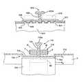
- FIG. 1is a partially schematic, partially cross-sectional side view of one embodiment of the present invention including a vessel in the form of a bag having a flexible portion and a rigid portion;
- FIG. 1 ais a partially schematic, partially cross-sectional, enlarged cutaway side view of the rigid portion of the vessel in the embodiment of FIG. 1 ;
- FIG. 1 bis a partially schematic, partially cross-sectional, enlarged cutaway side view of the fluid-agitating element in the embodiment of FIG. 1 ;
- FIG. 1 cis an enlarged partially cutaway side view showing one possible manner of attaching a first receiver in the form of a post to the rigid portion of the vessel;
- FIG. 2is a partially schematic, partially cross-sectional side view showing the vessel of FIG. 1 positioned in a rigid vessel, with the fluid-agitating element aligned with and levitated/rotated by an adjacent motive device;
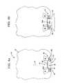
- FIG. 3 ais partially schematic, partially cross-sectional side view showing another embodiment of the vessel, including a hat or cap-shaped rigid portion having a cavity facing inwardly;
- FIG. 3 bis a side view similar to FIG. 3 a;
- FIG. 4 ais partially schematic, partially cross-sectional side view showing another embodiment of the vessel, including a hat or cap-shaped rigid portion having a cavity facing outwardly;
- FIG. 4 bis a side view similar to FIG. 4 a;
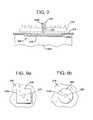
- FIGS. 5 a , 5 b , 6 a , 6 b , and 7 a , 7 bare each partially schematic, partially cross-sectional side views of a vessel with a rigid portion for aligning a fluid-agitating element with a external structure, wherein the fluid-agitating element is directly supported by a slide bearing;
- FIGS. 8 a and 8 bare enlarged, partially cross-sectional, partially cutaway side views of yet another embodiment of the vessel of the present invention.
- FIG. 9is an enlarged, partially cross-sectional, partially cutaway side view of yet another embodiment of the vessel of the present invention.
- FIGS. 9 a and 9 bare cutaway bottom views of the vessel of FIG. 9 a showing two different embodiments
- FIG. 10is an enlarged, partially cross-sectional, partially cutaway side view of still another embodiment of the vessel of the present invention.
- FIGS. 10 a and 10 bare cutaway bottom views of the vessel of FIG. 10 showing two different embodiments
- FIG. 11is an enlarged, partially cross-sectional, partially cutaway side view of another embodiment of the vessel of the present invention.
- FIGS. 11 a and 11 bare cutaway bottom views of the vessel of FIG. 11 showing two different embodiments
- FIG. 12is an enlarged, partially cross-sectional, partially cutaway side view of still another embodiment of the vessel of the present invention.
- FIG. 13is an enlarged, partially cross-sectional, partially cutaway side view of still another embodiment of the vessel of the present invention.
- FIGS. 13 a and 13 bare cutaway bottom views of the vessel of FIG. 13 showing two different embodiments
- FIG. 14is an enlarged, partially cross-sectional, partially cutaway side view of yet another embodiment of the vessel of the present invention.
- FIG. 15is an enlarged, partially cross-sectional, partially cutaway side view of a further embodiment of the vessel of the present invention.
- FIG. 15 ais a bottom view of the vessel of FIG. 15 showing two different embodiments.
- FIGS. 16 a and 16 bare enlarged, cross-sectional cutaway side views showing two different ways in which the rigid receiver may be connected to the bag forming the vessel;
- FIG. 17illustrates an alternative embodiment of a mixing bag with a coupler according to one aspect of the invention.
- FIG. 18is a schematic side view illustrating an embodiment of a mixing bag with a coupler according to one aspect of the invention.
- FIG. 1discloses one embodiment of the vessel of the present invention in the form of a bag 10 .
- the bag 10includes a body having a flexible or non-rigid portion 12 , which is illustrated schematically, and a rigid or stiff portion 14 , which is shown in cross-section.
- a flexible or non-rigid portion 12which is illustrated schematically
- a rigid or stiff portion 14which is shown in cross-section.
- the use of the many of the present inventive concepts disclosed herein with vessels that are completely rigidis also possible.
- the bag 10may be hermetically sealed and may have one or more openings or fittings (not shown) for introducing or recovering a fluid. Alternatively, the bag 10 may be unsealed or open-ended.
- the particular geometry of the bag 10 employednormally depends on the application and is not considered critical to the invention. For example, in the case of a sterile fluid, a hermetically sealed, pre-sterilized bag with an aseptic fitting might be desirable; whereas, in the case where sterility is not important, an open-ended or unsealed bag might be suitable.
- the main important pointis that the bag 10 is capable of receiving and at least temporarily holding a fluid (which is used herein to denote any substance capable of flowing, as may include liquids, liquid suspensions, gases, gaseous suspensions, or the like, without limitation).
- the rigid portion 14includes a first receiver 16 for receiving and holding a fluid-agitating element 18 at a home location (or expected position), when positioned in the bag 10 .
- “holding” as used hereindefines both the case where the fluid-agitating element 18 is directly held and supported by the first receiver 16 (see below) against any significant side-to-side movement (save tolerances), as well as where the first receiver 16 merely limits the fluid-agitating element to a certain degree of side-to-side movement within the bag 10 .
- an opening 18 ais provided in the fluid-agitating element 18 and the first receiver 16 is a post 20 projecting toward the interior of the bag 10 (see FIGS. 1 a and 1 b ).
- the post 20is sized for receiving the fluid-agitating element 18 bar extending through the opening 18 a formed in the body 18 b thereof (which is depicted as being annular, but not necessarily circular in cross-section). As illustrated in FIG. 1 , it is preferable that the size of the opening 18 a is such that the fluid-agitating element 18 may freely rotate and move in the axial direction along the post 20 without contacting the outer surface thereof. Despite this freedom of movement, the post 20 serving as the first receiver 16 is still considered to hold, confine, or keep the fluid-agitating element 18 at a home location or expected position within the vessel 20 by contacting the surface adjacent to the opening 18 a as a result of any side-to-side movement (the boundaries of which are defined by the dimensions of the opening).
- the flexible portion 12 of the bag 10may be made of thin (e.g., having a thickness of between 0.1 and 0.2 millimeters) polyethylene film.
- the filmis preferably clear or translucent, although the use of opaque or colored films is also possible.
- the rigid portion 14 including the post 20may be formed of plastic materials, such as high density polyethylene (HDPE), ultrahigh molecular weight (UHMW) polyethylene, or like materials. Of course, these materials do have some inherent flexibility when used to form relatively thin components or when a moderate amount of bending force is applied thereto. Despite this flexibility, the rigid portion 14 is distinguished from the flexible portion 12 , in that it generally maintains its shape under the weight of any fluid introduced in the bag 10 .
- HDPEhigh density polyethylene
- UHMWultrahigh molecular weight
- the post 20may include a portion 20 a for capturing the fluid-agitating element 18 and assisting in holding it thereon.
- the portion 20 ais preferably oversized and forms the head or end of the post 20 .
- oversizedit is meant that at least one dimension (length, width, diameter) of this portion 20 a of the post 20 is greater than the corresponding dimension of the opening 18 a in the fluid-agitating element 18 .
- the portion 20 ais shown in FIG. 1 as being disc-shaped, such that it provides the head end of the post 20 with a generally T-shaped cross section.
- the oversized portion 20 ais strategically positioned at a certain distance along the post 20 .
- the post 20may be removably attached to the rigid portion 14 through the opening 18 a in the fluid-agitating element 18 (such as by providing a threaded bore in the rigid portion for receiving a threaded end of the post, or as shown in FIG. 1 c a bore 14 a having a groove 14 b for establishing a snap-fit engagement with a corresponding projection 20 b on a tapered end portion 20 c of the post).
- this portionshould be sufficiently thin such that it flexes or temporarily deforms to allow the fluid-agitating element 18 to pass initially (see FIG. 1 b and note action arrow A, which demonstrates the direction of force for deforming the oversized head 20 a such that it passes through the opening 18 a ).
- this portion 20 a of the post 20need not be oversized, as defined above, but instead may simply be sufficiently close in size to that of the opening 15 a such that the fluid-agitating element 18 must be precisely aligned and register with the post 20 in order to be received or removed. In any case, it is again important to note that the fluid-agitating element 18 is held in place in the vicinity of the post 20 , but remains free of direct attachment.
- first receiver 16(post 20 ) confines or holds the fluid-agitating element 18 at a home location or expected position within the bag 10 , it is still free to move side-to-side to some degree (which in this case is defined by the size of the opening 18 a ), and to move along the first receiver 16 in the axial direction (vertical, in the embodiment shown in FIG. 1 ), as is necessary for levitation.
- the rigid portion 14 in this embodimentfurther includes a substantially planar peripheral flange 22 .
- the flange 22may be any shape or size, and is preferably attached or connected directly to the bag 10 at the interface I between the two structures (which may be created by overlapping the material forming the flexible portion 12 of the bag on an inside or outside surface of the flange 22 to form an overlapping joint, or possibly in some cases by forming a butt joint).
- the connectionmay be made using well-known techniques, such as ultrasonic or thermal welding (heat or laser) at the interface to form a seal (which is at least liquid-impervious and preferably hermetic).
- connectione.g., adhesives
- the judicious use of inert sealantsmay be made along the joint thus formed to ensure that a leak-proof, hermetic seal results.
- the need for such an interfacemay be altogether eliminated by simply affixing the rigid portion 14 to an inside or outside surface of the bag 10 (see FIGS. 16 a and 16 b ).
- the bag 10 shown in FIG. 1may be manufactured as described above, with the fluid-agitating element 18 received on the post 20 (which may be accomplished using the techniques shown in FIGS. 1 b and 1 c ).
- the empty bag 10may then be sealed and folded for shipping, with the fluid-agitating element 18 held at the home location by the post 20 .
- Holding in the axial directioni.e., the vertical direction in FIG. 1 ) may be accomplished by folding the bag 10 over the post 20 , or by providing the portion 20 a that is oversized or very close in size to the opening 18 a in the fluid-agitating element 18 .
- the bag 10When ready for use, the bag 10 is then unfolded. It may then be placed in a rigid or semi-rigid support structure, such as a container C, partially open along at least one end such that at least the rigid portion 14 remains exposed (see FIG. 2 ). Fluid F may then be introduced into the bag 10 , such as through an opening or fitting (which may be a sterile or aseptic fitting, in the case where the bag 10 is pre-sterilized or otherwise used in a sterile environment). As should be appreciated, in view of the flexible or non-rigid nature of the bag 10 , it will generally occupy any adjacent space provided in an adjacent support structure or container C when a fluid F (liquid or gas under pressure) is introduced therein (see FIG. 2 ).
- a fluid Fliquid or gas under pressure
- An external motive device 24is then used to cause the fluid-agitating element 18 (which is at least partially magnetic or ferromagnetic) to at least rotate to agitate any fluid F in the bag 10 .
- the fluid-agitating element 18is at least partially magnetic and is shown as being levitated by the motive device 24 , which is optional but desirable.
- the levitationmay be provided by a field-cooled, thermally isolated superconducting element SE (shown in phantom in FIG. 2 ) positioned within the motive device 24 and thermally linked to a cooling source (not shown).
- the fluid-agitating element 18may then be rotated by rotating the superconducting element SE (in which case the fluid-agitating element 18 should produce an asymmetric magnetic field, such as by using at least two spaced magnets having alternating polarities).
- a separate drive structuree.g., an electromagnetic coil
- a couplingcapable of transmitting torque to the particular fluid-agitating element (which may be “levitated” by a hydrodynamic bearing; see, e.g., U.S. Pat. No. 5,141,327 to Shiobara).
- the fluid-agitating element 18is also depicted as including a plurality of vanes or blades B to improve the degree of fluid agitation. If present, the vanes or blades B preferably project in a direction opposite the corresponding surface of the rigid portion 14 .
- the particular number, type, and form of the vanes or blades Bis not considered important, as long as the desired degree of fluid agitation for the particular application is provided. Indeed, in applications where only gentle agitation is required, such as to prevent damage to delicate suspensions or to merely prevent stagnation of the fluid F in the bag 10 , the vanes or blades B need not be provided, as a rotating smooth-walled annular element 18 still provides some degree of agitation.
- the rigid portion 14may be provided with a second receiver 26 to facilitate the correct positioning of the motive device 24 relative to the fluid-agitating element 18 when held at the home location.
- the second receiver 26takes the form of a second post 28 projecting in a direction opposite the first post 20 .
- the second post 28is essentially coaxial with the first post 20 (although the post 20 may be a separate component that fits into a receiver 14 a defined by the second post 28 ; see FIG.
- the second post 28helps to assure that the alignment between the fluid-agitating element 18 (which is generally held in the vicinity of the first receiver 16 /post 20 , which is the home location) and the motive device 14 is proper such that the desired coupling for transmitting the levitation or rotational force may be formed.
- the second receiver 26such as second post 28
- the second post 28may be square in cross-section for fitting in a correspondingly-shaped opening 24 a or locator bore.
- the second post 28could have a triangular cross-sectional shape, in which case the opening 28 would be triangular.
- Myriad other shapescould also be used, as long as the shape of the second receiver 26 compliments that of the opening 24 a such that it may be freely received therein.
- a system of matching receivers and openingsmay be used to ensure that the fluid-agitating element 18 in the bag 10 corresponds to a particular motive device 24 .
- the second receiver 26may be provided with a certain shape that corresponds only to the opening 24 in the motive device 24 having that type of superconducting element or drive structure.
- a similar resultcould also be achieved using the relative sizes of the second receiver 26 and the opening 24 a , as well as by making the size of the opening 18 a in the fluid-agitating element 18 such that it only fits on a first receiver 16 having a smaller width or diameter, and then making the second receiver 26 correspond only to an opening 24 a in a motive device 24 corresponding to that fluid-agitating element 18 .
- the motive device 24 in the embodiments disclosed herein for use with a vessel in the form of a bag 10is generally supported from a stable support structure (not shown), such as the floor, a wheeled, height adjustable platform, or the like. Since there is thus no direct attachment with the bag 10 , the function performed by the second receiver 26 in aligning this device with the fluid-agitating element 18 is an important one.
- FIGS. 3 a and 3 bAnother embodiment of the vessel forming one aspect of the present invention is shown in FIGS. 3 a and 3 b .
- the vesselis again a bag 10 including a flexible portion 12 and a rigid portion 14 .
- the rigid portion 14is cap or hat-shaped with a peripheral flange 22 for attachment to the flexible portion 12 of the bag 10 .
- the connection between the two structuresmay be formed using the various techniques described above, and preferably results in a fluid-impervious, hermetic seal.
- the rigid portion 14includes a first receiver 16 in the form of a recess or cavity facing the interior of the bag (see action arrow B) for receiving a correspondingly-shaped portion of the fluid-agitating element 18 in the bag 10 and holding it at a home location, at least when oriented as shown in FIG. 3 a .
- the portion of the fluid-agitating element 18 received in the cavity 30is preferably the body 18 b , which as described above is at least partially magnetic or ferromagnetic and may optionally support a plurality of vanes or blades B.
- the body 18 b of the fluid-agitating element 18is circular in cross-section and the cavity 30 is sized and shaped such that the body (which need not include opening 18 a in view of the absence of post 20 ) may freely be inserted, rotate, and levitate therein.
- the fluid-agitating element 18could also be in the form of a conventional magnetic stirrer (which of course would not be levitated), such as a bar having a major dimension less than the corresponding dimension (e.g., the diameter) of the cavity 30 .
- the fluid-agitating element 18 in this embodimentis again free of direct attachment from the first receiver 16 , but is held at a home location, even in the event of accidental decoupling.
- the fluid-agitating element 18may be positioned in the first receiver 16 in the bag 10 .
- the bag 10may then be sealed, folded for storage or shipping, stored or shipped, and ultimately unfolded for use.
- the foldingis preferably completed such that the fluid-agitating element 18 is captured in the cavity 30 and remains held in place during shipping by an adjacent portion of the bag 10 . Consequently, upon unfolding the bag 10 , the fluid-agitating element 18 is at the expected or home location, but remains free of direct attachment and ready to be rotated (and possibly levitated).
- the levitation height established by the superconducting bearing or hydrodynamic bearingis preferably such that least a portion of the body 18 b of the fluid-agitating element 18 remains within the confines of the cavity 30 .
- the fluid-agitating element 18will engage the sidewall of the cavity 30 and simply come to rest therein, which defines the home location. This not only improves the chance of an automatic recoupling, but also makes the task of manually reforming the coupling an easy one.
- An option to assure that a magnetic fluid agitating element 18 remains associated with the first receiver 16 , even if inverted,is to attach an attractive structure, such as a magnet 32 (shown in phantom in FIG. 3 a ), to the exterior of the rigid portion 14 .
- the non-contact coupling thus establishedhelps ensure that the fluid-agitating element 18 remains in the home location prior to being coupled to an external motive device.
- the magnet 32is removed once the bag 10 is positioned on or in a support structure, such as a container C (see FIG. 2 ).
- a magnet 32may also be used with the embodiment of FIG. 1 , which eliminates the need for providing the post 20 with portion 20 a .
- the magnet 32is preferably annular with an opening that is received by the second receiver 26 , which advantageously helps to ensure that the alignment is proper for forming the coupling.
- any adhesive usedis preferably such that the bond is easily broken when the fluid-agitating element 18 is levitated in the first receiver 16 .
- the use of such an adhesivemight not be possible in situations where strict regulations govern the purity of the fluid being mixed.
- the first receiver 16 in this embodimentalso serves the dual function of helping to align the fluid-agitating element 18 relative to an external motive device 24 .
- the periphery of the sidewall 34 and the end wall 36 defining the cavity 30 in the rigid portion 14define a second receiver 26 adapted to receive an opening 24 a formed in an adjacent face of a motive device 24 .
- the opening 24 ais preferably sized and shaped for being received by the second receiver 26 , and may even help to ensure that the bag 10 is used only with a motive device 24 having the correct superconducting element or magnetic structure(s) for levitating and/or rotating the fluid-agitating element 18 .
- the opening 24 ais also cylindrical.
- the opening 24 aalso has a depth such that the end wall 36 rests on the corresponding face 24 c of the motive device 24 .
- This featuremay be important to ensure that the gap between the superconducting element and/or drive structure in the motive device 24 and the at least partially magnetic or ferromagnetic body 18 b of the fluid-agitating element 18 is minimized, which helps to ensure that the strongest possible coupling is established and that the maximum amount of driving torque is transferred.
- the gapsare shown as being oversized in FIG. 3 b merely to provide a clear depiction of the relative interaction of the structures shown.
- FIGS. 4 a and 4 bshow an embodiment similar in some respects to the one shown in FIGS. 3 a and 3 b .
- the rigid portion 14includes a peripheral flange 22 connected to the flexible portion 12 of the bag 10 to form a seal.
- the rigid portion 14includes a sidewall 34 and end wall 26 that together define a cavity 30 .
- a major differenceis that the cavity 30 of the rigid portion 14 essentially faces outwardly, or toward the exterior of the bag 10 (e.g., in a direction opposite action arrow B).
- the sidewall 34 and end wall 36define the first receiver 16 for receiving the fluid-agitating element 18 , which is shown having an annular body 18 b that is at least partially magnetic or ferromagnetic and may support a plurality of vanes or blades B.
- the first receiver 16 in the form of the periphery of the sidewall 34provides a similar receiving function as both the post 20 and the cavity 30 of the other embodiments, since it is capable of maintaining, holding, or confining the fluid-agitating element 18 substantially in a home or expected position within the bag 10 .
- the maximum amount of side-to-side movementis of course dependent on the size of the opening 15 a in the fluid-agitating element.
- the outwardly-facing cavity 30is adapted to serve as the second receiver 26 for receiving a portion of a motive device 24 used to levitate and rotate the fluid-agitating element 18 and serving to align the two.
- the motive device 24may include a head end 24 d adapted for insertion in the cavity 30 to form the desired coupling with the fluid-agitating element 18 positioned adjacent thereto.
- the spacing between the head end 24 d and at least the sidewall 34is preferably minimized to maximize the strength of the coupling between the motive device 24 and the fluid-agitating element 18 .
- the end face 24 b of the head end 24 dmay rest against and assist in supporting the bag 10 (which, as described above, may be positioned in a separate, semi-rigid container (not shown)).
- an added advantage of the use of the first receiver 16 in each of the above-referenced embodimentsis that, despite being free from direct attachment, it still serves the function of holding the fluid-agitating element 18 at the home location in instances where accidental decoupling occurs. This significantly reduces the downtime associated with such an event, since the general position of the fluid-agitating element 18 is known.
- the use of a first receiver in the bag 10also improves the chances of automatic recoupling, since the fluid-agitating element 18 remains generally centered relative to the motive device 14 and held generally at the home location, even when decoupling occurs.
- a related advantageis provided by forming the first receiver 16 in or on a rigid portion 14 of the bag 10 .
- the contact over timecould result in damage and could even lead to an accidental perforation, which is deleterious for obvious reasons.
- the possibility for such damage or perforationalso exists when a levitating fluid-agitating element 18 accidentally decouples.
- the potential for such damage or perforationis substantially eliminated in the foregoing embodiments, since the first receiver 16 helps to keep the fluid-agitating element 18 adjacent to the flange 22 of the rigid portion 14 , which is generally thicker and less susceptible to being damaged or perforated.
- the fluid-agitating element 18becomes decoupled, it only engages or contacts the rigid portion 14 of the bag 10 .
- the flange 22it is preferable for the flange 22 to be oversized relative to the fluid-agitating element 18
- FIGS. 1-4are described as bags 10 including both a flexible portion 12 and a rigid portion 14 , it should be appreciated that the present invention extends to a completely rigid vessel (that is, one made of metal, glass, rigid plastics, or the like).
- the post 20preferably includes a portion 20 a for capturing the fluid-agitating element 18 thereon, but without any other means of direct attachment or bearing.
- the inventions described hereinmay also be applied to a bag 10 in combination with a fluid-agitating element 18 directly supported by one or more bearings.
- the first receiver 16 associated with the rigid portion 14 of the bag 10may be in the form of an inwardly-projecting post 20 including a slide bearing 40 for providing direct support for the fluid-agitating element 18 .
- the bearing 40is preferably sized and shaped such that it fits into an opening 18 a forming in the fluid-agitating element 18 , which may rest on the adjacent surface of the post 20 or may be elevated slightly above it. In either case, it should be appreciated that the first receiver 16 receives and holds the fluid-agitating element 18 in a home location, both during shipping and later use.
- the material forming the slide bearing 40is preferably highly wear-resistant with good tribological characteristics.
- the use of a slide bearing 40is preferred in applications where the bag 10 is disposable and is merely discarded, since it is less expensive than a corresponding type of mechanical roller bearing (and is actually preferred even in the case where the bag 10 is reused, since it is easier to clean).
- it is within the broadest aspects of the invention to provide the first receiver 16 with a conventional roller bearing for providing direct, low-friction, rolling support for the rotating fluid-agitating element 18although this increases the manufacturing expense and may not be acceptable in certain applications.
- the rigid portion 14 of the bag 10 in this embodimentmay further include a second receiver 26 in the form of a second post 28 coextensive and coaxial with the first post 20 .
- the second post 28is received in an opening 24 a formed in an end face 24 b of a motive device 24 .
- the motive device 24in this case includes only a drive structure DS (shown in phantom in FIG. 5 b ) for forming a coupling with the body 18 b , which is magnetic or ferromagnetic (iron, magnetic steel, etc.).
- the drive structure DSmay be a permanent magnet or may be ferromagnetic, as necessary for forming the coupling with the fluid-agitating element 18 , which may be disc-shaped, cross-shaped, an elongated bar, or have any other suitable shape.
- the drive structure DSmay be rotated by a direct connection with a motor (not shown), such as a variable speed electric motor, to induce rotation in the fluid-agitating element 18 .
- the drive structure DSmay be an electromagnet with windings to which current is supplied to cause the magnetic fluid-agitating element 18 rotate and possibly levitate slightly to create a hydrodynamic bearing (see, e.g., U.S. Pat. No. 5,141,327, the disclosure of which is incorporated herein by reference).
- the particular type of motive device 24 employedis not considered critical to the present invention.
- FIGS. 6 a and 6 bshow an embodiment of the bag 10 in which the first receiver 16 is in the form of a cavity 30 formed in the rigid portion 14 and facing inwardly.
- a bearing 40is provided in the cavity 30 for providing direct support for a fluid-agitating element 18 positioned therein.
- the bearing 40may be a slide bearing adapted for insertion in the opening 15 a of the fluid-agitating element 18 formed on the head end of a post 42 .
- the post 42may be supported by or unitarily formed with the end wall 36 .
- the body 18 b of the fluid-agitating element 18which is at least partially magnetic or ferromagnetic, is sized to fit within the sidewall 34 defining the cavity 30 and, thus, is capable of rotating therein as the result of an externally-applied, non-contact motive force.
- the periphery of the sidewall 34also defines a second receiver 26 for receiving a corresponding opening 24 a in a motive device 24 , which in view of the direct support provided by bearing 40 need only provide the force necessary to rotate the fluid-agitating element 18 in a non-contact fashion.
- the rigid portion 14again includes a cavity 30 facing outwardly or toward the exterior of the bag 10 and a first receiver 16 for receiving and defining a home location for a fluid-agitating element 18 .
- the first receiver 16includes a bearing 40 for supporting the fluid-agitating element 18 , which again is at least partially magnetic or ferromagnetic.
- the bearing 40may be a slide bearing formed on the head end of a post 44 integral with the end wall 36 of the rigid portion 14 and adapted for fitting into an opening or recess 18 a in the fluid-agitating element 18 , or may be a different type of bearing for providing support therefor.
- the motive device 24includes a head end 24 d adapted for insertion in a second receiver 26 defined by the cavity 30 .
- This head end 24 dpreferably includes the drive structure DS that provides the force for causing the at least partially magnetic or ferromagnetic fluid-agitating element 18 to rotate about bearing 40 .
- the fluid-agitating element 18includes an optional depending portion 18 b that extends over the sidewall 34 . As should be appreciated, this portion may also be magnetized or ferromagnetic such that a coupling is formed with the drive structure DS.
- a similar type of fluid-agitating element 18could also be used in the levitation scheme of FIGS. 4 a and 4 b.
- FIGS. 8 a and 8 bshow another possible embodiment of a vessel of the present invention for use in a fluid-agitating or mixing system.
- the vessel for holding the fluidis shown as being a bag 110 having a flexible portion 112 , generally cylindrical in shape, and substantially or hermetically sealed from the ambient environment.
- the bag 110includes a first receiver 116 for receiving and holding the fluid-agitating element 118 at a home location.
- the first receiver 116is in the form of a post 120 adapted to receive the fluid-agitating element 118 , which has a corresponding opening 118 a .
- the post 120preferably includes an oversized head portion 120 a that captures the fluid-agitating element 118 , both before and after a fluid is introduced into the bag 110 .
- the bag 110may be manufactured, sealed (if desired), shipped, or stored prior to use with the fluid-agitating element 118 held in place on the post 120 .
- the vessel 110may also be sterilized as necessary for a particular application, and in the case of a flexible bag, may even be folded for compact storage.
- the post 120also serves the advantageous function of keeping, holding, maintaining, or confining the fluid-agitating element 118 substantially at a home location or “centered,” should it accidentally become decoupled from the adjacent motive device, which as described above may include a rotating superconducting element SE for not only providing the rotational force, but also a levitation force.
- the post 120is shown as being defined by an elongated, rigid or semi-rigid, rod-like structure inserted through an opening typically found in the flexible plastic bags frequently used in the bioprocessing industry (pharmaceuticals, food products, cell cultures, etc.), such as a rigid or semi-rigid fitting or nipple 134 .
- the oversized portion 120 awhich is shown as being T-shaped in cross-section, is preferably sufficiently thin and/or formed of a material that may flex or deform to easily pass through the opening in the nipple 134 , as well as through the opening 118 a in the fluid-agitating element 118 .
- a conventional clamp 136such as a cable tie, may be used to form a fluid-impervious seal between the nipple 134 and the post 120 .
- Any other nipples or fittings presentmay be used for introducing the fluid F prior to mixing, retrieving a fluid during mixing or after mixing is complete, or circulating the fluid.
- the use of the rod/nipple combinationallows for easy retrofitting.
- the oversized head portion 120 amay be cross-shaped, L-shaped, Y-shaped, spherical, cubic, or may have any other shape, as long as the corresponding function of capturing the fluid-agitating element 118 is provided.
- the head portion 120 amay be integrally formed, or may be provided as a separate component clamped or fastened to the post 120 .
- the bag 110may also include a second receiver 126 that helps to ensure that proper alignment is achieved between the fluid-agitating element 118 and an adjacent structure, such as a support structure or a device for rotating and/or levitating the element.
- this second receiver 126is shown as the opposite end 128 of the rod forming post 120 .
- This end 128 of the rodmay be inserted in a bore or opening 124 a in an adjacent surface of a motive device 124 to assure proper alignment with the fluid-agitating element 113 .
- assuranceis thus provided that the fluid-agitating element 118 is in the desired home or expected position for forming a coupling with an adjacent motive device 124 .
- FIG. 8 aalso shows the post 120 forming the first receiver 116 as projecting upwardly from a bottom wall of the vessel 110 , but as should be appreciated, it could extend from any wall or other portion thereof.
- the rod serving as both the first and second receivers 116 , 126may be positioned substantially perpendicular to a vertical plane.
- the bag 110is positioned in a rigid or semi-rigid support container C having an opening O.
- the end 128 of the rodis positioned in the opening O such that it projects therefrom and may be inserted in the opening 124 a formed in the motive device 124 , which includes a superconducting element SE and may still levitate, and possibly rotate the at least partially magnetic fluid-agitating element 118 in this position.
- the portion of the rod extending outside the bag 110 and forming the second receiver 126is greater in length than that in the embodiment shown in FIG.
- the depth of the opening 124 a in the motive device 124corresponds to this length. This in combination with the rigid or semi-rigid nature of the nipple 134 helps to ensure that the other end of the rod forming post 120 is properly aligned with the fluid-agitating element 118 when the magnetic coupling is formed.
- a first receiver 216 in the form of a post 220includes an oversized spherical head 220 a that serves to mechanically capture an adjacent fluid-agitating element 218 (shown in phantom).
- the post 220is integrally formed with the vessel, which is preferably a bag 210 but may be partially or completely rigid.
- a low-profile second receiver 226 in the form of an outwardly-directed projection 228is provided for receiving a corresponding portion 224 a of the adjacent motive device 224 .
- the projection 228may have any shape desired, including square, circular, or the like (see FIGS.
- the vessel 310may be rigid or at least partially flexible.
- the first receiver 316is a post 320 which is shown merely for purposes of illustration as having an L-shaped head portion 320 a for mechanically capturing an adjacent fluid-agitating element 318 (shown in phantom).
- the second receiver 326is in the form of at least one projection 328 substantially concentric with the post 320 .
- the projection 328may be square, circular, or may have any other desired shape.
- the projectionmay also be continuous, as shown in FIG. 10 a , or interrupted to form segments 328 a , 328 b . . . 328 n , as shown in FIG. 10 b .
- the corresponding portion 324 a of the motive device 324 that is received by the second receiver 326is similarly shaped and preferably continuous, but could also have one or more segments matching the segments in the vessel 310 (including a single offset bore).
- the vessel 410includes a first receiver 416 in the form of a post 420 , again shown with an oversized T-shaped head 420 a .
- the second receiver 426includes at least one channel, recess, or groove 428 formed in the vessel 410 .
- a corresponding projection 425is provided in the motive device 424 for engaging the channel, recess or groove 428 to provide the desired alignment function, such as between driving magnets and driven magnets, between driven magnets and a rotating superconducting element, or between any other driver and a driven structure associated with a fluid-agitating element.
- the channel, groove, or recess 428is preferably continuous (see FIG. 11 a , with the projection 425 shown in phantom), but may be segmented as well (see FIG. 11 b ).
- the vessel 510again includes a first receiver 516 in the form of a post 520 , which is shown for purposes of illustration as having a frusto-conical head to create a Y-shaped cross-section.
- the second receiver 526is in the form of a low-profile recessed portion 528 formed in the vessel 510 .
- This recessed portion 528is sized and shaped for receiving a portion of the motive device 510 , and thus ensures that the proper alignment is achieved between a fluid-agitating element 518 concentric with the post 520 and any structure for levitating and/or rotating the element.
- the recessed portion 528may have any shape desired, including square, circular, triangular, rectangular, polygonal, or the like.
- FIG. 13illustrates an embodiment wherein the vessel 610 is provided with a first receiver 616 in the form of a post 620 having a head 620 a (shown as disc-shaped), as well as a plurality of structures 628 defining second receivers 626 adapted for receiving a portion of an external structure, such as a projection 625 formed on an end face of a motive device 624 .
- the second receivers 626may be in the form of concentric ring-shaped recesses 628 , as illustrated in FIG. 13 a , but could also comprise concentric squares or even arrays of straight lines, as shown in FIG. 13 b . Three second receivers 626 are shown in FIGS.
- FIG. 14shows an embodiment wherein the vessel 710 , which again may be rigid or partially flexible, includes a first receiver 716 in the form of a post 720 having an oversized head portion 720 a and a second receiver 726 in the form of a hat or cup-shaped projection 728 (which may be integrally formed or a separate rigid portion).
- the second receiver 726receives a portion of an intermediate support structure T including a first recess R 1 on one side and a second recess R 2 on the opposite side.
- the second recess R 2is adapted for receiving at least a portion of the motive device 724 , which is shown as a cryostat including a rotating, thermally isolated superconducting element SE for coupling with at least two alternating polarity magnets M (or alternatively, the head of the cryostat may be attached to a bearing positioned in recess R 2 and rotated).
- This particular embodimentdispenses with the need for forming a locator bore in the motive device 724 to align the fluid-agitating element 718 therewith (although it remains possible to provide such a bore for receiving a projection on the support structure T to achieve the alignment function).
- FIG. 15shows an embodiment where a second receiver 826 in the form of a slightly raised projection 828 is provided in the vessel 810 that corresponds to a dimple 825 formed in an external structure, such as the end face of the motive device 824 .
- the opposite arrangementcould also be used, with the dimple formed in the vessel 810 and serving as a second receiver 826 .
- at least one indiciamay be provided to allow an observer to determine the proper location of the structure such as motive device 824 relative to the vessel 810 .
- the indiciais shown as a darkened ring 866 formed in the outer wall of the vessel 810 , which could be a bag or a rigid or semi-rigid container. However, it should be appreciated that the indicia could be in the form of one or more marks placed on or formed in the outer surface of the vessel 810 (including even possibly a weld or seal line), or even marks placed on the opposite sides of an intermediate support surface (not shown).
- the indicia 866is preferably designed such that it helps to align the motive device 824 relative to a first receiver 816 in the vessel 810 for receiving and defining a home location for a fluid agitating element, such as the post 820 (which is shown having a cross-shaped head 820 a ). The indicia 866 thus helps to ensure that the fluid-agitating element is aligned with any driving or levitating structure held therein.
- This coupler 922is thus attracted to and forms a magnetic coupling with the magnetic fluid-agitating element 902 when the attachment 920 is in place.
- the attachment 920should be fabricated of a non-magnetic material, such as rubber.
- the coupler 922 when made of a ferromagnetic materialwill shield the magnetic field created by the fluid-agitating element 902 .
- the attachment 920may simply be removed from the bag 900 to break the magnetic coupling between the fluid-agitating element 902 and the coupler 922 , such that the arrangement is ready for agitating any fluid F provided.
- FIG. 18shows an embodiment in which the coupler 32 forming the attachment is associated with the container C for purposes of holding a magnetic fluid-agitating element 18 (which is shown as a magnetic impeller with blades B) in place.
- the coupler 32holds or retains the element 18 at a home location within a mixing bag 10 having a flexible portion 12 (sidewall) received in the interior compartment of the container C.
- the bag 10is shown in FIG. 18 as being oversized and spaced relative to the sidewalls defining the interior compartment of the container C. However, this is for purposes of illustration only.
- the container Cmay be a shipping box or like structure for receiving and delivering the bag 10 and fluid-agitating element 18 to a site for use in mixing a fluid.
- the material forming the container Cis more rigid that the relatively thin, flexible material used to form at least a portion of the bag 10 .
- the bag 10is shown without any rigid portion or like structure for receiving the fluid-agitating element 18 , it should be appreciated that one may be provided.
- the coupler 32may comprise a magnet (e.g., a permanent magnet or a ferromagnetic material), for forming a magnetic coupling with the magnetic field of the fluid-agitating element.
- the coupler 32is preferably affixed to the interior surface of a wall of the container C using an adhesive, strap, magnet, or like structure. Hence, as shown, the arrangement may be such that the coupler 32 is positioned between an external surface of the bag 10 and an interior surface of the container C when the two are nested.
- the fluid-agitating element 18may be anchored in place by the coupler 32 during shipping of the bag 10 with the container C, which helps to reduce the chance of deleterious perforation that might otherwise result.
- the coupling with coupler 32is simply broken, and the magnetic fluid-agitating element 18 associated with a suitable motive device external to the container C, as shown for example in FIG. 2 . Mixing of a fluid introduced to the bag 12 may then proceed in the desired fashion.
- the rigid portion 14as part of the bag 10 by forming a seal at an interface between the two, it could also be positioned in contact to an inner or outer surface of the bag and attached using vacuum-forming techniques, adhesives, or the like.
- the bag 10would essentially line the inside surfaces of the sidewall 34 and end wall 36 (see FIG. 16 a ).
- the bag 10would cover the sidewall 34 and end wall 36 (see FIG. 16 b ). In both cases, the need for the flange 22 may be eliminated.
- any of the first receiverswith a tapered or frusto-conical engagement surface that mates with a corresponding surface on the fluid-agitating element, as disclosed in my co-pending patent application Ser. No. PCT/US01/31459.
Landscapes
- Chemical & Material Sciences (AREA)
- Chemical Kinetics & Catalysis (AREA)
- Mixers With Rotating Receptacles And Mixers With Vibration Mechanisms (AREA)
Abstract
Description
Claims (33)
Priority Applications (2)
| Application Number | Priority Date | Filing Date | Title |
|---|---|---|---|
| US11/829,194US8182137B2 (en) | 2000-10-09 | 2007-07-27 | Mixing bag or vessel with a fluid-agitating element |
| US13/476,200US9221024B2 (en) | 2000-10-09 | 2012-05-21 | Mixing bag or vessel with a fluid-agitating element |
Applications Claiming Priority (15)
| Application Number | Priority Date | Filing Date | Title |
|---|---|---|---|
| US23918700P | 2000-10-09 | 2000-10-09 | |
| US09/724,815US6758593B1 (en) | 2000-10-09 | 2000-11-28 | Pumping or mixing system using a levitating magnetic element, related system components, and related methods |
| US28292701P | 2001-04-10 | 2001-04-10 | |
| US31857901P | 2001-09-11 | 2001-09-11 | |
| US32683301P | 2001-10-03 | 2001-10-03 | |
| US10/398,946US7086778B2 (en) | 2000-10-09 | 2001-10-09 | System using a levitating, rotating pumping or mixing element and related methods |
| PCT/US2001/031459WO2002041484A2 (en) | 2000-10-09 | 2001-10-09 | Systems using a levitating, rotating pumping or mixing element and related methods |
| US10/120,006US6837613B2 (en) | 2001-04-10 | 2002-04-10 | Sterile fluid pumping or mixing system and related method |
| PCT/US2002/031478WO2003028869A2 (en) | 2001-10-03 | 2002-10-02 | Mixing bag or vessel having a receiver for a fluid-agitating element |
| US10/491,512US7481572B2 (en) | 2001-10-03 | 2002-10-02 | Mixing bag or vessel having a receiver for a fluid-agitating element |
| US10/863,910US6899454B2 (en) | 2000-10-09 | 2004-06-09 | Set-up kit for a pumping or mixing system using a levitating magnetic element |
| US11/028,777US7357567B2 (en) | 2001-04-10 | 2005-01-04 | Sterile fluid pumping or mixing system and related method |
| US11/113,677US7267479B2 (en) | 2000-10-09 | 2005-04-25 | Magnetic coupler for holding a magnetic pumping or mixing element in a vessel |
| US11/496,702US7434983B2 (en) | 2000-10-09 | 2006-07-31 | Systems using a levitating, rotating pumping or mixing element and related methods |
| US11/829,194US8182137B2 (en) | 2000-10-09 | 2007-07-27 | Mixing bag or vessel with a fluid-agitating element |
Related Parent Applications (9)
| Application Number | Title | Priority Date | Filing Date |
|---|---|---|---|
| US10/398,946Continuation-In-PartUS7086778B2 (en) | 2000-10-09 | 2001-10-09 | System using a levitating, rotating pumping or mixing element and related methods |
| PCT/US2001/031459Continuation-In-PartWO2002041484A2 (en) | 2000-10-09 | 2001-10-09 | Systems using a levitating, rotating pumping or mixing element and related methods |
| US10/491,512Continuation-In-PartUS7481572B2 (en) | 2000-10-09 | 2002-10-02 | Mixing bag or vessel having a receiver for a fluid-agitating element |
| PCT/US2002/031478Continuation-In-PartWO2003028869A2 (en) | 2000-10-09 | 2002-10-02 | Mixing bag or vessel having a receiver for a fluid-agitating element |
| US10491512Continuation-In-Part | 2002-10-02 | ||
| US11/028,777Continuation-In-PartUS7357567B2 (en) | 2000-10-09 | 2005-01-04 | Sterile fluid pumping or mixing system and related method |
| US11/113,677Continuation-In-PartUS7267479B2 (en) | 2000-10-09 | 2005-04-25 | Magnetic coupler for holding a magnetic pumping or mixing element in a vessel |
| US11/496,702Continuation-In-PartUS7434983B2 (en) | 2000-10-09 | 2006-07-31 | Systems using a levitating, rotating pumping or mixing element and related methods |
| US11/829,194Continuation-In-PartUS8182137B2 (en) | 2000-10-09 | 2007-07-27 | Mixing bag or vessel with a fluid-agitating element |
Related Child Applications (4)
| Application Number | Title | Priority Date | Filing Date |
|---|---|---|---|
| US10/863,910DivisionUS6899454B2 (en) | 2000-10-09 | 2004-06-09 | Set-up kit for a pumping or mixing system using a levitating magnetic element |
| US11/496,702ContinuationUS7434983B2 (en) | 2000-10-09 | 2006-07-31 | Systems using a levitating, rotating pumping or mixing element and related methods |
| US11/829,194Continuation-In-PartUS8182137B2 (en) | 2000-10-09 | 2007-07-27 | Mixing bag or vessel with a fluid-agitating element |
| US13/476,200ContinuationUS9221024B2 (en) | 2000-10-09 | 2012-05-21 | Mixing bag or vessel with a fluid-agitating element |
Publications (2)
| Publication Number | Publication Date |
|---|---|
| US20070263484A1 US20070263484A1 (en) | 2007-11-15 |
| US8182137B2true US8182137B2 (en) | 2012-05-22 |
Family
ID=38684963
Family Applications (2)
| Application Number | Title | Priority Date | Filing Date |
|---|---|---|---|
| US11/829,194Expired - Fee RelatedUS8182137B2 (en) | 2000-10-09 | 2007-07-27 | Mixing bag or vessel with a fluid-agitating element |
| US13/476,200Expired - Fee RelatedUS9221024B2 (en) | 2000-10-09 | 2012-05-21 | Mixing bag or vessel with a fluid-agitating element |
Family Applications After (1)
| Application Number | Title | Priority Date | Filing Date |
|---|---|---|---|
| US13/476,200Expired - Fee RelatedUS9221024B2 (en) | 2000-10-09 | 2012-05-21 | Mixing bag or vessel with a fluid-agitating element |
Country Status (1)
| Country | Link |
|---|---|
| US (2) | US8182137B2 (en) |
Cited By (11)
| Publication number | Priority date | Publication date | Assignee | Title |
|---|---|---|---|---|
| US20140334249A1 (en)* | 2013-05-08 | 2014-11-13 | Roxi Group, Inc. | Beverage mixing, storing and dispensing apparatus |
| US9010993B1 (en) | 2010-06-25 | 2015-04-21 | Bradford D. Overton | Apparatus, system and method for mixing and dispensing dental impression materials |
| US9221024B2 (en)* | 2000-10-09 | 2015-12-29 | Pall Technology Uk Limited | Mixing bag or vessel with a fluid-agitating element |
| EP3034108A1 (en)* | 2014-12-18 | 2016-06-22 | B. Braun Avitum AG | Concentrate container for an extracorporeal blood treatment machine, and a concentrate supplying system for extracorporeal blood treatment machine |
| US20170259228A1 (en)* | 2014-03-17 | 2017-09-14 | Advanced Scientifics, Inc. | Transportable mixing system for biological and pharmaceutical materials |
| US10260036B2 (en) | 2014-10-17 | 2019-04-16 | Sani-Tech West, Inc. | Mixing and filtering system and method |
| US10583409B2 (en) | 2016-03-31 | 2020-03-10 | General Electric Company | Axial flux stator |
| US11097236B2 (en) | 2016-03-31 | 2021-08-24 | Global Life Sciences Solutions Usa Llc | Magnetic mixers |
| WO2022175938A1 (en)* | 2021-02-17 | 2022-08-25 | Shalev Evyatar | System for mixing liquid |
| US11958026B2 (en) | 2021-09-15 | 2024-04-16 | Sanisure, Inc. | Low volume magnetic mixing system |
| DE102024127973B3 (en)* | 2024-09-26 | 2025-07-17 | Wolfgang Pätzold | Device with cooling function |
Families Citing this family (20)
| Publication number | Priority date | Publication date | Assignee | Title |
|---|---|---|---|---|
| US7086778B2 (en)* | 2000-10-09 | 2006-08-08 | Levtech, Inc. | System using a levitating, rotating pumping or mixing element and related methods |
| AU2002362448A1 (en)* | 2001-10-03 | 2003-04-14 | Levtech, Inc. | Mixing bag or vessel having a receiver for a fluid-agitating element |
| EP1701780B8 (en)* | 2004-01-07 | 2014-09-24 | Pall Technology UK limited | Bioprocessing vessel with integral sparger, and method of its manufacture |
| DE502006008592D1 (en)* | 2005-07-29 | 2011-02-10 | Zeta Biopharma Gmbh | magnetic |
| WO2008040567A1 (en)* | 2006-10-03 | 2008-04-10 | Artelis | Flexible mixing bag, mixing device and mixing system |
| SG166108A1 (en)* | 2005-10-26 | 2010-11-29 | Levtech Inc | Bioreactor with mixer and sparger |
| WO2007134267A2 (en) | 2006-05-13 | 2007-11-22 | Advanced Technology Materials, Inc. | Disposable bioreactor |
| US8814422B2 (en) | 2011-05-17 | 2014-08-26 | Tol-O-Matic, Inc. | Eddy current motor, eddy current coupling system, and method of use |
| US9339026B2 (en) | 2012-06-14 | 2016-05-17 | Therapeutic Proteins International, LLC | Pneumatically agitated and aerated single-use bioreactor |
| US9321558B2 (en)* | 2012-09-19 | 2016-04-26 | Perimeter Brand Packaging, Llc | Insert assembly for beverage container |
| US9815035B2 (en) | 2013-06-28 | 2017-11-14 | Saint-Gobain Performance Plastics Corporation | Mixing assemblies including magnetic impellers |
| US11944946B2 (en) | 2013-06-28 | 2024-04-02 | Saint-Gobain Performance Plastics Corporation | Mixing assemblies including magnetic impellers |
| CN105451615B (en)* | 2013-08-05 | 2018-02-16 | 夏普株式会社 | Stirring blades, stirring devices, beverage making devices and stirring sections |
| JP6797417B2 (en) | 2015-04-16 | 2020-12-09 | グローバル・ライフ・サイエンシズ・ソリューションズ・ユーエスエー・エルエルシー | Bio process mixer |
| JP6068709B2 (en)* | 2015-05-18 | 2017-01-25 | シャープ株式会社 | Stirrer and stirrer |
| EP3115103B1 (en)* | 2015-07-06 | 2021-04-21 | Levitronix GmbH | Mixing device and disposable device for a mixing device |
| BR112018014583A2 (en)* | 2016-01-22 | 2018-12-11 | Saint Gobain Performance Plastics Corp | fluid mixing system |
| WO2019050976A1 (en) | 2017-09-06 | 2019-03-14 | Access Medical Systems, Ltd. | Ferromagnetic rotors for agitating the liquid in a microwell |
| US20190184353A1 (en)* | 2017-12-20 | 2019-06-20 | Sartorius Stedim Biotech Gmbh | Insertable components for single-use containers |
| US12384995B2 (en) | 2017-12-20 | 2025-08-12 | Sartorius Stedim Biotech Gmbh | Insertable components for single-use containers |
Citations (84)
| Publication number | Priority date | Publication date | Assignee | Title |
|---|---|---|---|---|
| DE1082122B (en) | 1952-03-26 | 1960-05-19 | Edmund Buehler | Circulation and mixing pump for submersible operation |
| US3002895A (en) | 1957-02-11 | 1961-10-03 | Freedman David | Incubator-shaker apparatus |
| US3362692A (en)* | 1966-01-13 | 1968-01-09 | Edmund F. Iannone | Container with stirring means |
| US3583682A (en) | 1969-03-19 | 1971-06-08 | Alwin Berents | Mixing machine |
| US3647397A (en) | 1969-11-19 | 1972-03-07 | Charles M Coleman | Reagent solution preparation |
| US3940052A (en) | 1971-11-03 | 1976-02-24 | Mchugh Vincent Kenneth | Unitary container liner |
| US3962892A (en) | 1973-05-29 | 1976-06-15 | Garlinghouse Leslie H | Machine for controlled conditioning of liquids and mixtures |
| US4162855A (en) | 1974-11-18 | 1979-07-31 | Spectroderm International, Inc. | Magnetic stirrer apparatus |
| US4209259A (en)* | 1978-11-01 | 1980-06-24 | Rains Robert L | Magnetic mixer |
| EP0033292A1 (en) | 1980-01-25 | 1981-08-05 | Dubernard Hospital S.A. | Device for artificial feeding |
| US4290300A (en)* | 1978-10-18 | 1981-09-22 | Joseph Carver | Sucrose density gradient system |
| GB2076677A (en) | 1980-04-23 | 1981-12-09 | Thomas Thomas Ronal | Magnetic stirring elements |
| US4356967A (en) | 1980-09-15 | 1982-11-02 | Lunaire Environmental, Inc. | Laboratory incubator chamber system |
| DE3246330A1 (en) | 1982-12-15 | 1984-06-20 | Haagen & Rinau, 2800 Bremen | Device for mixing at least two substances |
| US4498785A (en) | 1982-06-09 | 1985-02-12 | Techne Corporation | Floating magnetic stirrer for culture medium |
| JPS6167476A (en) | 1984-09-10 | 1986-04-07 | Shibata Hario Glass Kk | Apparatus for vegetable cell culture |
| JPS61212275A (en) | 1985-03-16 | 1986-09-20 | Shibaura Eng Works Co Ltd | Bioreactor furnished with actuator |
| US4621521A (en)* | 1984-02-25 | 1986-11-11 | Th. Goldschmidt Ag | Apparatus for determining foam formation of crude petroleum |
| EP0200792A1 (en) | 1985-02-01 | 1986-11-12 | Herbert Prof. Dr.-Ing. Märkl | Foil fermenter |
| US4649118A (en)* | 1984-04-05 | 1987-03-10 | The Virtis Company, Inc. | Cell culturing apparatus with improved stirring and filter means |
| US4668632A (en) | 1985-02-06 | 1987-05-26 | Vxr, Inc. | Sparger and apparatus for and method of growing cells |
| US4711582A (en) | 1986-11-07 | 1987-12-08 | Kennedy Richard B | Rotary mixing of two component resins in disposable plastic bag |
| JPS6336825A (en) | 1986-07-28 | 1988-02-17 | Satake Kagaku Kikai Kogyo Kk | Agitation device |
| GB2202549A (en)* | 1987-03-20 | 1988-09-28 | Philip John Whitney | Foldable fermenter |
| US4783172A (en) | 1985-10-03 | 1988-11-08 | Garg Raj P | Respirometer |
| US4808348A (en) | 1987-05-14 | 1989-02-28 | The Coca-Cola Company | Microgravity carbonator |
| US4836826A (en)* | 1987-12-18 | 1989-06-06 | The United States Of America As Represented By The Administrator Of The National Aeronautics And Space Administration | Magnetic drive coupling |
| EP0343885A1 (en) | 1988-05-19 | 1989-11-29 | P.B. Ind. Plant Biotech Industries Ltd. | Air lift fermentor formed from flexible plastic sheets |
| DE3818776A1 (en) | 1988-06-02 | 1989-12-07 | Maerkl Herbert | Process for the cultivation of cells in a fermenter, and fermenter intended for carrying out the process |
| EP0375413A1 (en) | 1988-12-22 | 1990-06-27 | Robbins, Edward S., III | Thin film container with a removable lid, and process for forming the same |
| US4978616A (en) | 1985-02-28 | 1990-12-18 | Verax Corporation | Fluidized cell cultivation process |
| EP0433463A1 (en) | 1989-06-26 | 1991-06-26 | Meiji Milk Products Company Limited | Rotary culture device |
| JPH03242297A (en) | 1990-02-19 | 1991-10-29 | Komatsu Ltd | Fine bubble generation air diffuser |
| US5061448A (en) | 1988-04-29 | 1991-10-29 | Barnstead Thermolyne Corporation | Incubator |
| US5141327A (en)* | 1989-03-10 | 1992-08-25 | Satake Chemical Equipment Mfg., Ltd. | Stirrer |
| US5176446A (en)* | 1989-10-16 | 1993-01-05 | Shigeru Chiba | Magnetic type agitator which is capable of generating ultrasonic wave |
| JPH0631626A (en) | 1992-07-19 | 1994-02-08 | Daikin Ind Ltd | Polishing device |
| EP0590473A1 (en) | 1992-10-01 | 1994-04-06 | Mavag Verfahrenstechnik Ag | Impeller for stirring sterile liquids |
| JPH06153902A (en) | 1992-11-19 | 1994-06-03 | Shibata Hario Glass Kk | Culture tank |
| US5362642A (en)* | 1993-02-10 | 1994-11-08 | Hyclone Laboratories | Methods and containment system for storing, reconstituting, dispensing and harvesting cell culture media |
| US5407272A (en)* | 1992-10-01 | 1995-04-18 | Mavag Verfahrenstechnik Ag. | Double impeller for stirring sterile liquids |
| US5501971A (en) | 1993-01-29 | 1996-03-26 | New Brunswick Scientific Co., Inc. | Method and apparatus for anchorage and suspension cell culture |
| US5533804A (en)* | 1992-03-19 | 1996-07-09 | Gambro Kk | Process for preparing a stock solution composition for a medical treatment, and a soft bag having a magnetic stirrer to be used in the preparation of said stock solution composition |
| DE19542227A1 (en) | 1995-11-13 | 1997-05-15 | Norman Kunz | Packaging for materials sensitive to air contact |
| US5750440A (en)* | 1995-11-20 | 1998-05-12 | Motorola, Inc. | Apparatus and method for dynamically mixing slurry for chemical mechanical polishing |
| US5779359A (en) | 1996-12-05 | 1998-07-14 | General Signal Corporation | Mixer having exposed clean-in-place bearing assemblies |
| WO1998033538A1 (en) | 1997-02-04 | 1998-08-06 | Novo Nordisk A/S | A device for the administration of a liquid medicament suspension |
| US5803137A (en)* | 1995-07-24 | 1998-09-08 | Beldex Corporation | Liquid crystal delivering apparatus |
| JPH10314569A (en) | 1997-05-16 | 1998-12-02 | Hiroshi Miyauchi | Agitating device |
| JPH10313718A (en) | 1997-05-22 | 1998-12-02 | Toshiba Eng & Constr Co Ltd | Apparatus and method for culturing plant pieces |
| US5941635A (en) | 1997-06-11 | 1999-08-24 | Hyclone Labortories, Inc. | Mixing block for resuspension system |
| US5988422A (en) | 1998-07-16 | 1999-11-23 | Stedim, Z.I. Des Paluds | Sachets for bio-pharmaceutical fluid products |
| WO2000011953A1 (en) | 1998-09-01 | 2000-03-09 | Penn State Research Foundation | Method and apparatus for aseptic growth or processing of biomass |
| US6071005A (en) | 1996-06-11 | 2000-06-06 | Merck & Co., Inc. | Disposable storage, transport and resuspension system |
| US6247840B1 (en) | 1998-01-15 | 2001-06-19 | Shaik A. Gaffar | Dialysis container with sample saver |
| DE20114076U1 (en) | 2001-08-29 | 2001-10-25 | Hebold Gmbh & Co Kg App Und An | Homogenizer, especially for the bottom of a mixing and stirring tank |
| US20010039369A1 (en) | 1999-12-14 | 2001-11-08 | Terentiev Alexandre N. | Blood pump system |
| US20020082173A1 (en) | 1999-01-04 | 2002-06-27 | Terentiev Alexandre N. | Pumping or mixing system using a levitating magnetic element |
| US20020091371A1 (en) | 2001-01-08 | 2002-07-11 | Ritter Franz Peter | Salt container system for dialysis apparatus |
| US20020105856A1 (en) | 2001-02-06 | 2002-08-08 | Alexandre Terentiev | Apparatus and method for mixing materials sealed in a container under sterile conditions |
| US20020145940A1 (en) | 2001-04-10 | 2002-10-10 | Terentiev Alexandre N. | Sterile fluid pumping or mixing system and related method |
| US20030226857A1 (en) | 2002-04-12 | 2003-12-11 | Hyclone Laboratories, Inc. | Systems for forming sterile fluid connections and methods of use |
| US6670171B2 (en) | 2001-07-09 | 2003-12-30 | Wheaton Usa, Inc. | Disposable vessel |
| US20040047232A1 (en) | 2000-10-09 | 2004-03-11 | Terentiev Alexandre N. | System using a levitating, rotating pumping or mixing element and related methods |
| US20040062140A1 (en) | 2002-09-27 | 2004-04-01 | Cadogan David Phillip | Bioprocess container, bioprocess container mixing device and method of use thereof |
| EP1462155A1 (en) | 2003-03-28 | 2004-09-29 | Hyclone Laboratories, Inc. | Container systems for mixing fluids with a magnetic stir bar |
| US20040218468A1 (en) | 2000-10-09 | 2004-11-04 | Terentiev Alexandre N. | Set-up kit for a pumping or mixing system using a levitating magnetic element |
| US20040221897A1 (en) | 2003-05-09 | 2004-11-11 | Stedim | Disposable container for use in fluid processing |
| US20040252582A1 (en) | 2001-02-22 | 2004-12-16 | Bucher Franz G | Device for mixing and homogenizing materials in laboratory test container with a stirring element |
| US20050002274A1 (en) | 2001-10-03 | 2005-01-06 | Terentiev Alexandre N. | Mixing bag or vessel having a receiver for a fluid-agitating element |
| WO2005037658A2 (en) | 2003-10-14 | 2005-04-28 | Advanced Technology Materials, Inc. | A flexible mixing bag for mixing solids, liquids and gases |
| US20050127215A1 (en) | 2003-11-24 | 2005-06-16 | Roche Diagnostics Operations, Inc. | Device for comminuting agglomerates, in particular by breaking up microparticles by piston movement in a container |
| WO2005082508A1 (en) | 2004-03-01 | 2005-09-09 | Novaseptic Ab | Processing unit |
| WO2005118771A2 (en) | 2004-06-04 | 2005-12-15 | Xcellerex, Inc. | Disposable bioreactor systems and methods |
| WO2006002091A2 (en) | 2004-06-23 | 2006-01-05 | Levtech, Inc. | Mixing vessel alignment systems, devices, and related methods |
| US20060092761A1 (en) | 2000-10-09 | 2006-05-04 | Terentiev Alexandre N | Mixing vessel with a fluid-agitating element supported by a roller bearing |
| WO2006063087A2 (en) | 2004-12-09 | 2006-06-15 | Levtech, Inc. | Mixing vessel with a fluid-agitating element supported by a roller bearing |
| US20060131765A1 (en) | 2004-01-07 | 2006-06-22 | Terentiev Alexandre N | Mixing bag with integral sparger and sensor receiver |
| WO2007039600A1 (en) | 2005-10-04 | 2007-04-12 | Artelis | Method of cell cultures and device for implementing it |
| US20070201993A1 (en) | 2006-02-28 | 2007-08-30 | Terentiev Alexandre N | Disposable pumping apparatus based on flexible vessels in pressurized containers |
| US20070220956A1 (en) | 2006-03-22 | 2007-09-27 | Terentiev Alexandre N | Apparatus and methods for leak detection in bioprocessing bags |
| US20070263484A1 (en)* | 2000-10-09 | 2007-11-15 | Terentiev Alexandre N | Mixing bag or vessel with a fluid-agitating element |
| WO2008040568A1 (en) | 2006-10-03 | 2008-04-10 | Artelis | Mixing system including a flexible bag, specific flexible bag and locating system for the mixing system |
| WO2008040567A1 (en) | 2006-10-03 | 2008-04-10 | Artelis | Flexible mixing bag, mixing device and mixing system |
Family Cites Families (10)
| Publication number | Priority date | Publication date | Assignee | Title |
|---|---|---|---|---|
| DE7031863U (en)* | 1970-08-26 | 1971-01-14 | Ippen Heiko Arlac Werk | STORAGE AND REMOVAL TANK FOR MAGNETIZABLE OBJECTS. |
| US3868016A (en)* | 1973-03-05 | 1975-02-25 | Medicotech Company | Magnetized surgical instrument tray restraint |
| US4150746A (en)* | 1977-10-19 | 1979-04-24 | Buglione Victor A | Tool box appliance |
| US4214874A (en)* | 1979-02-08 | 1980-07-29 | American Hospital Supply Corporation | Combination and method for mixing the contents of a blood collection tube and thereafter removing the mixing element |
| US4830511A (en)* | 1986-10-29 | 1989-05-16 | The Coca-Cola Company | Postmix juice dispensing system |
| US5356373A (en)* | 1991-11-15 | 1994-10-18 | Miles Inc. | Method and apparatus for autologous transfusions in premature infants |
| US5760668A (en)* | 1996-01-16 | 1998-06-02 | Testa; Joseph F. | Magnetic tool and object holder |
| US5941867A (en)* | 1997-07-15 | 1999-08-24 | Kao; Ti | Formulation of pharmaceutical solutions in free fall |
| US6520335B2 (en)* | 2001-02-20 | 2003-02-18 | Daniel E. Moran | Method and container for packaging multi-component polymer coatings and adhesives |
| US6786349B2 (en)* | 2002-11-18 | 2004-09-07 | Fadi Najd | Tip-resistant refuse container |
- 2007
- 2007-07-27USUS11/829,194patent/US8182137B2/ennot_activeExpired - Fee Related
- 2012
- 2012-05-21USUS13/476,200patent/US9221024B2/ennot_activeExpired - Fee Related
Patent Citations (97)
| Publication number | Priority date | Publication date | Assignee | Title |
|---|---|---|---|---|
| DE1082122B (en) | 1952-03-26 | 1960-05-19 | Edmund Buehler | Circulation and mixing pump for submersible operation |
| US3002895A (en) | 1957-02-11 | 1961-10-03 | Freedman David | Incubator-shaker apparatus |
| US3362692A (en)* | 1966-01-13 | 1968-01-09 | Edmund F. Iannone | Container with stirring means |
| US3583682A (en) | 1969-03-19 | 1971-06-08 | Alwin Berents | Mixing machine |
| US3647397A (en) | 1969-11-19 | 1972-03-07 | Charles M Coleman | Reagent solution preparation |
| US3940052A (en) | 1971-11-03 | 1976-02-24 | Mchugh Vincent Kenneth | Unitary container liner |
| US3962892A (en) | 1973-05-29 | 1976-06-15 | Garlinghouse Leslie H | Machine for controlled conditioning of liquids and mixtures |
| US4162855A (en) | 1974-11-18 | 1979-07-31 | Spectroderm International, Inc. | Magnetic stirrer apparatus |
| US4290300A (en)* | 1978-10-18 | 1981-09-22 | Joseph Carver | Sucrose density gradient system |
| US4209259A (en)* | 1978-11-01 | 1980-06-24 | Rains Robert L | Magnetic mixer |
| EP0033292A1 (en) | 1980-01-25 | 1981-08-05 | Dubernard Hospital S.A. | Device for artificial feeding |
| GB2076677A (en) | 1980-04-23 | 1981-12-09 | Thomas Thomas Ronal | Magnetic stirring elements |
| US4356967A (en) | 1980-09-15 | 1982-11-02 | Lunaire Environmental, Inc. | Laboratory incubator chamber system |
| US4498785A (en) | 1982-06-09 | 1985-02-12 | Techne Corporation | Floating magnetic stirrer for culture medium |
| DE3246330A1 (en) | 1982-12-15 | 1984-06-20 | Haagen & Rinau, 2800 Bremen | Device for mixing at least two substances |
| US4621521A (en)* | 1984-02-25 | 1986-11-11 | Th. Goldschmidt Ag | Apparatus for determining foam formation of crude petroleum |
| US4649118A (en)* | 1984-04-05 | 1987-03-10 | The Virtis Company, Inc. | Cell culturing apparatus with improved stirring and filter means |
| JPS6167476A (en) | 1984-09-10 | 1986-04-07 | Shibata Hario Glass Kk | Apparatus for vegetable cell culture |
| EP0200792A1 (en) | 1985-02-01 | 1986-11-12 | Herbert Prof. Dr.-Ing. Märkl | Foil fermenter |
| US4668632A (en) | 1985-02-06 | 1987-05-26 | Vxr, Inc. | Sparger and apparatus for and method of growing cells |
| US4978616A (en) | 1985-02-28 | 1990-12-18 | Verax Corporation | Fluidized cell cultivation process |
| JPS61212275A (en) | 1985-03-16 | 1986-09-20 | Shibaura Eng Works Co Ltd | Bioreactor furnished with actuator |
| US4783172A (en) | 1985-10-03 | 1988-11-08 | Garg Raj P | Respirometer |
| JPS6336825A (en) | 1986-07-28 | 1988-02-17 | Satake Kagaku Kikai Kogyo Kk | Agitation device |
| US4711582A (en) | 1986-11-07 | 1987-12-08 | Kennedy Richard B | Rotary mixing of two component resins in disposable plastic bag |
| GB2202549A (en)* | 1987-03-20 | 1988-09-28 | Philip John Whitney | Foldable fermenter |
| US4808348A (en) | 1987-05-14 | 1989-02-28 | The Coca-Cola Company | Microgravity carbonator |
| US4836826A (en)* | 1987-12-18 | 1989-06-06 | The United States Of America As Represented By The Administrator Of The National Aeronautics And Space Administration | Magnetic drive coupling |
| US5061448A (en) | 1988-04-29 | 1991-10-29 | Barnstead Thermolyne Corporation | Incubator |
| EP0343885A1 (en) | 1988-05-19 | 1989-11-29 | P.B. Ind. Plant Biotech Industries Ltd. | Air lift fermentor formed from flexible plastic sheets |
| DE3818776A1 (en) | 1988-06-02 | 1989-12-07 | Maerkl Herbert | Process for the cultivation of cells in a fermenter, and fermenter intended for carrying out the process |
| EP0375413A1 (en) | 1988-12-22 | 1990-06-27 | Robbins, Edward S., III | Thin film container with a removable lid, and process for forming the same |
| US5141327A (en)* | 1989-03-10 | 1992-08-25 | Satake Chemical Equipment Mfg., Ltd. | Stirrer |
| EP0433463A1 (en) | 1989-06-26 | 1991-06-26 | Meiji Milk Products Company Limited | Rotary culture device |
| US5270207A (en) | 1989-06-26 | 1993-12-14 | Meiji Milk Products Company Limited | Circulatory culture equipment |
| US5176446A (en)* | 1989-10-16 | 1993-01-05 | Shigeru Chiba | Magnetic type agitator which is capable of generating ultrasonic wave |
| JPH03242297A (en) | 1990-02-19 | 1991-10-29 | Komatsu Ltd | Fine bubble generation air diffuser |
| US5533804A (en)* | 1992-03-19 | 1996-07-09 | Gambro Kk | Process for preparing a stock solution composition for a medical treatment, and a soft bag having a magnetic stirrer to be used in the preparation of said stock solution composition |
| JPH0631626A (en) | 1992-07-19 | 1994-02-08 | Daikin Ind Ltd | Polishing device |
| EP0590473A1 (en) | 1992-10-01 | 1994-04-06 | Mavag Verfahrenstechnik Ag | Impeller for stirring sterile liquids |
| US5407272A (en)* | 1992-10-01 | 1995-04-18 | Mavag Verfahrenstechnik Ag. | Double impeller for stirring sterile liquids |
| JPH06153902A (en) | 1992-11-19 | 1994-06-03 | Shibata Hario Glass Kk | Culture tank |
| US5501971A (en) | 1993-01-29 | 1996-03-26 | New Brunswick Scientific Co., Inc. | Method and apparatus for anchorage and suspension cell culture |
| US5362642A (en)* | 1993-02-10 | 1994-11-08 | Hyclone Laboratories | Methods and containment system for storing, reconstituting, dispensing and harvesting cell culture media |
| US5803137A (en)* | 1995-07-24 | 1998-09-08 | Beldex Corporation | Liquid crystal delivering apparatus |
| DE19542227A1 (en) | 1995-11-13 | 1997-05-15 | Norman Kunz | Packaging for materials sensitive to air contact |
| US5750440A (en)* | 1995-11-20 | 1998-05-12 | Motorola, Inc. | Apparatus and method for dynamically mixing slurry for chemical mechanical polishing |
| US6071005A (en) | 1996-06-11 | 2000-06-06 | Merck & Co., Inc. | Disposable storage, transport and resuspension system |
| US5779359A (en) | 1996-12-05 | 1998-07-14 | General Signal Corporation | Mixer having exposed clean-in-place bearing assemblies |
| WO1998033538A1 (en) | 1997-02-04 | 1998-08-06 | Novo Nordisk A/S | A device for the administration of a liquid medicament suspension |
| JPH10314569A (en) | 1997-05-16 | 1998-12-02 | Hiroshi Miyauchi | Agitating device |
| JPH10313718A (en) | 1997-05-22 | 1998-12-02 | Toshiba Eng & Constr Co Ltd | Apparatus and method for culturing plant pieces |
| US5941635A (en) | 1997-06-11 | 1999-08-24 | Hyclone Labortories, Inc. | Mixing block for resuspension system |
| US6247840B1 (en) | 1998-01-15 | 2001-06-19 | Shaik A. Gaffar | Dialysis container with sample saver |
| US5988422A (en) | 1998-07-16 | 1999-11-23 | Stedim, Z.I. Des Paluds | Sachets for bio-pharmaceutical fluid products |
| WO2000011953A1 (en) | 1998-09-01 | 2000-03-09 | Penn State Research Foundation | Method and apparatus for aseptic growth or processing of biomass |
| US6245555B1 (en) | 1998-09-01 | 2001-06-12 | The Penn State Research Foundation | Method and apparatus for aseptic growth or processing of biomass |
| US20020082173A1 (en) | 1999-01-04 | 2002-06-27 | Terentiev Alexandre N. | Pumping or mixing system using a levitating magnetic element |
| US20010039369A1 (en) | 1999-12-14 | 2001-11-08 | Terentiev Alexandre N. | Blood pump system |
| US20050201201A1 (en) | 2000-10-09 | 2005-09-15 | Terentiev Alexandre N. | Magnetic coupler for holding a magnetic pumping or mixing element in a vessel |
| US7695186B2 (en)* | 2000-10-09 | 2010-04-13 | Levtech, Inc. | Systems using a levitating, rotating pumping or mixing element and related methods |
| US20090129201A1 (en)* | 2000-10-09 | 2009-05-21 | Terentiev Alexandre N | Mixing Bag or Vessel Having a Fluid-Agitating Element |
| US20090034364A1 (en)* | 2000-10-09 | 2009-02-05 | Terentiev Alexandre N | Systems using a levitating, rotating pumping or mixing element and related methods |
| US20070263484A1 (en)* | 2000-10-09 | 2007-11-15 | Terentiev Alexandre N | Mixing bag or vessel with a fluid-agitating element |
| US20040047232A1 (en) | 2000-10-09 | 2004-03-11 | Terentiev Alexandre N. | System using a levitating, rotating pumping or mixing element and related methods |
| US20070030759A1 (en) | 2000-10-09 | 2007-02-08 | Terentiev Alexandre N | Systems using a levitating, rotating pumping or mixing element and related methods |
| US20060092761A1 (en) | 2000-10-09 | 2006-05-04 | Terentiev Alexandre N | Mixing vessel with a fluid-agitating element supported by a roller bearing |
| US20040218468A1 (en) | 2000-10-09 | 2004-11-04 | Terentiev Alexandre N. | Set-up kit for a pumping or mixing system using a levitating magnetic element |
| US20020091371A1 (en) | 2001-01-08 | 2002-07-11 | Ritter Franz Peter | Salt container system for dialysis apparatus |
| US20020105856A1 (en) | 2001-02-06 | 2002-08-08 | Alexandre Terentiev | Apparatus and method for mixing materials sealed in a container under sterile conditions |
| US20040252582A1 (en) | 2001-02-22 | 2004-12-16 | Bucher Franz G | Device for mixing and homogenizing materials in laboratory test container with a stirring element |
| US20050117449A1 (en) | 2001-04-10 | 2005-06-02 | Terentiev Alexandre N. | Sterile fluid pumping or mixing system and related method |
| US20020145940A1 (en) | 2001-04-10 | 2002-10-10 | Terentiev Alexandre N. | Sterile fluid pumping or mixing system and related method |
| US6670171B2 (en) | 2001-07-09 | 2003-12-30 | Wheaton Usa, Inc. | Disposable vessel |
| DE20114076U1 (en) | 2001-08-29 | 2001-10-25 | Hebold Gmbh & Co Kg App Und An | Homogenizer, especially for the bottom of a mixing and stirring tank |
| US20050002274A1 (en) | 2001-10-03 | 2005-01-06 | Terentiev Alexandre N. | Mixing bag or vessel having a receiver for a fluid-agitating element |
| US7481572B2 (en)* | 2001-10-03 | 2009-01-27 | Levtech, Inc. | Mixing bag or vessel having a receiver for a fluid-agitating element |
| US20030226857A1 (en) | 2002-04-12 | 2003-12-11 | Hyclone Laboratories, Inc. | Systems for forming sterile fluid connections and methods of use |
| US20040062140A1 (en) | 2002-09-27 | 2004-04-01 | Cadogan David Phillip | Bioprocess container, bioprocess container mixing device and method of use thereof |
| US7153021B2 (en) | 2003-03-28 | 2006-12-26 | Hyclone Laboratories, Inc. | Container systems for mixing fluids with a magnetic stir bar |
| EP1462155A1 (en) | 2003-03-28 | 2004-09-29 | Hyclone Laboratories, Inc. | Container systems for mixing fluids with a magnetic stir bar |
| US7278780B2 (en) | 2003-03-28 | 2007-10-09 | Hyclone Laboratories, Inc. | Container systems for mixing fluids with a magnetic stir bar |
| US20040221897A1 (en) | 2003-05-09 | 2004-11-11 | Stedim | Disposable container for use in fluid processing |
| WO2005037658A2 (en) | 2003-10-14 | 2005-04-28 | Advanced Technology Materials, Inc. | A flexible mixing bag for mixing solids, liquids and gases |
| US20050127215A1 (en) | 2003-11-24 | 2005-06-16 | Roche Diagnostics Operations, Inc. | Device for comminuting agglomerates, in particular by breaking up microparticles by piston movement in a container |
| US20060131765A1 (en) | 2004-01-07 | 2006-06-22 | Terentiev Alexandre N | Mixing bag with integral sparger and sensor receiver |
| US20070252290A1 (en) | 2004-01-07 | 2007-11-01 | Terentiev Alexandre N | Mixing bag with integral sparger and sensor receiver |
| WO2005082508A1 (en) | 2004-03-01 | 2005-09-09 | Novaseptic Ab | Processing unit |
| WO2005118771A2 (en) | 2004-06-04 | 2005-12-15 | Xcellerex, Inc. | Disposable bioreactor systems and methods |
| WO2006002091A2 (en) | 2004-06-23 | 2006-01-05 | Levtech, Inc. | Mixing vessel alignment systems, devices, and related methods |
| US20080008028A1 (en) | 2004-06-23 | 2008-01-10 | Levtech, Inc. | Mixing vessel alignment systems, devices, and related methods |
| WO2006063087A2 (en) | 2004-12-09 | 2006-06-15 | Levtech, Inc. | Mixing vessel with a fluid-agitating element supported by a roller bearing |
| WO2007039600A1 (en) | 2005-10-04 | 2007-04-12 | Artelis | Method of cell cultures and device for implementing it |
| US20070201993A1 (en) | 2006-02-28 | 2007-08-30 | Terentiev Alexandre N | Disposable pumping apparatus based on flexible vessels in pressurized containers |
| US20070220956A1 (en) | 2006-03-22 | 2007-09-27 | Terentiev Alexandre N | Apparatus and methods for leak detection in bioprocessing bags |
| WO2008040567A1 (en) | 2006-10-03 | 2008-04-10 | Artelis | Flexible mixing bag, mixing device and mixing system |
| WO2008040568A1 (en) | 2006-10-03 | 2008-04-10 | Artelis | Mixing system including a flexible bag, specific flexible bag and locating system for the mixing system |
Non-Patent Citations (17)
| Title |
|---|
| ATMI Newmix® -Levtech® Disposable Mixing and Storage Systems, ATMI, Danbury, CT downloaded from www.atmi-lifesciences.com/html/newmix.html on Jan. 4, 2010. |
| ATMI, Inc., ATMI LifeSciences Newmix(TM) Jet-Drive(TM) is Your Benchmark for Disposable, Contained, Ultra-Clean Mixing, Launch of Revolutionary Mixing Technology, Apr. 16, 2007, pp. 1-2, Hoegaarden, Belgium. |
| ATMI, Inc., ATMI LifeSciences Newmix™ Jet-Drive™ is Your Benchmark for Disposable, Contained, Ultra-Clean Mixing, Launch of Revolutionary Mixing Technology, Apr. 16, 2007, pp. 1-2, Hoegaarden, Belgium. |
| Bosco et al., ATMI completes its Newmix(TM) range with ARTELIS(TM) single-use mixing technology, pp. 1, posted publicly exhibited at Bioproduction Dublin Conference, Dublin, Ireland, Oct. 24, 2006. |
| Bosco et al., ATMI completes its Newmix™ range with ARTELIS™ single-use mixing technology, pp. 1, posted publicly exhibited at Bioproduction Dublin Conference, Dublin, Ireland, Oct. 24, 2006. |
| Disposable Bioreactors Gaining Favor, New Components and Systems Improve Process Reliability and Reduce Cost, Genetic Engineering & biotechnology News, Jun. 15, 2006, vol. 26, No. 12, pp. 1-8. |
| GE Healthcare Life Sciences-WAVE Bioreactor Home, WAVE Bioreactor Systems, http://www4.gelifesciences.com/APTRIX/upp01077.nsf/Content/wave-bioreactor-home, pp. 1-2, downloaded Jan. 4, 2010, General Electric Co., Schenectady, New York. |
| GE Healthcare Life Sciences—WAVE Bioreactor Home, WAVE Bioreactor Systems, http://www4.gelifesciences.com/APTRIX/upp01077.nsf/Content/wave—bioreactor—home, pp. 1-2, downloaded Jan. 4, 2010, General Electric Co., Schenectady, New York. |
| Hyclone Americas, Mixtainer(TM), An integrated single-use sterile system for mixing and maintaining homogenous aqueous solutions, pp. 1-2, believed to be available at least as early as Jul. 12, 2007. |
| Hyclone Americas, Mixtainer™, An integrated single-use sterile system for mixing and maintaining homogenous aqueous solutions, pp. 1-2, believed to be available at least as early as Jul. 12, 2007. |
| LevTech, Inc. Business Plan, Sep. 5, 2000, pp. 1, 8-9, 11-13, 25. |
| Mechanical drawing of Bottom Drain Barrel believed to have been sold by Hyclone Laboratories, Inc., at least as early as Jan. 2002, as cited in US 7,278,780. |
| Pending claims in U.S. Appl. No. 12/444,040, filed Apr. 2, 2009 (national stage of PCT/EPC7/53998). |
| Russ Musch, Product Brief Form for HyClone Bioprocess Containers, May 31, 2001, pp. 1-3. |
| Schoeb, A Bearingless Motor for a Left Ventricular Assist Device, 7th International Symposium on Magnetic Bearings, Zurich, Switzerland, Aug. 23-25, 2000. |
| United States Postal Service, Mailing Standards of the United States Postal Service Publication 52-Hazardous, Restricted, and Perishable Mail, Jul. 1999, p. 315. |
| United States Postal Service, Mailing Standards of the United States Postal Service Publication 52—Hazardous, Restricted, and Perishable Mail, Jul. 1999, p. 315. |
Cited By (19)
| Publication number | Priority date | Publication date | Assignee | Title |
|---|---|---|---|---|
| US9221024B2 (en)* | 2000-10-09 | 2015-12-29 | Pall Technology Uk Limited | Mixing bag or vessel with a fluid-agitating element |
| US9010993B1 (en) | 2010-06-25 | 2015-04-21 | Bradford D. Overton | Apparatus, system and method for mixing and dispensing dental impression materials |
| US20140334249A1 (en)* | 2013-05-08 | 2014-11-13 | Roxi Group, Inc. | Beverage mixing, storing and dispensing apparatus |
| US12343695B2 (en) | 2014-03-17 | 2025-07-01 | Advanced Scientifics, Inc. | Transportable mixing system for biological and pharmaceutical materials |
| US20170259228A1 (en)* | 2014-03-17 | 2017-09-14 | Advanced Scientifics, Inc. | Transportable mixing system for biological and pharmaceutical materials |
| US10399049B2 (en)* | 2014-03-17 | 2019-09-03 | Advanced Scientifics, Inc. | Transportable mixing system for biological and pharmaceutical materials |
| US11179687B2 (en) | 2014-03-17 | 2021-11-23 | Advanced Scientifics, Inc. | Transportable mixing system for biological and pharmaceutical materials |
| US10501720B2 (en) | 2014-10-17 | 2019-12-10 | Sani-Tech West, Inc. | Mixing and filtering system |
| US10260036B2 (en) | 2014-10-17 | 2019-04-16 | Sani-Tech West, Inc. | Mixing and filtering system and method |
| DE102014119106A1 (en)* | 2014-12-18 | 2016-07-07 | B. Braun Avitum Ag | Concentrate container for an extracorporeal blood treatment machine, and concentrate delivery system for an extracorporeal blood treatment machine |
| US10449287B2 (en) | 2014-12-18 | 2019-10-22 | B. Braun Avitum Ag | Concentrate container for an extracorporeal blood treatment machine and a concentrate supply system for an extracorporeal blood treatment machine |
| EP3034108A1 (en)* | 2014-12-18 | 2016-06-22 | B. Braun Avitum AG | Concentrate container for an extracorporeal blood treatment machine, and a concentrate supplying system for extracorporeal blood treatment machine |
| US10583409B2 (en) | 2016-03-31 | 2020-03-10 | General Electric Company | Axial flux stator |
| US11097236B2 (en) | 2016-03-31 | 2021-08-24 | Global Life Sciences Solutions Usa Llc | Magnetic mixers |
| US11969701B2 (en) | 2016-03-31 | 2024-04-30 | Global Life Sciences Solutions Usa Llc | Magnetic mixers |
| WO2022175938A1 (en)* | 2021-02-17 | 2022-08-25 | Shalev Evyatar | System for mixing liquid |
| US11958026B2 (en) | 2021-09-15 | 2024-04-16 | Sanisure, Inc. | Low volume magnetic mixing system |
| US12377392B2 (en) | 2021-09-15 | 2025-08-05 | Sanisure, Inc. | Low volume magnetic mixing system |
| DE102024127973B3 (en)* | 2024-09-26 | 2025-07-17 | Wolfgang Pätzold | Device with cooling function |
Also Published As
| Publication number | Publication date |
|---|---|
| US20070263484A1 (en) | 2007-11-15 |
| US20120281494A1 (en) | 2012-11-08 |
| US9221024B2 (en) | 2015-12-29 |
Similar Documents
| Publication | Publication Date | Title |
|---|---|---|
| US8182137B2 (en) | Mixing bag or vessel with a fluid-agitating element | |
| US8282269B2 (en) | Mixing bag or vessel having a fluid-agitating element | |
| US7762716B2 (en) | Mixing vessel with a fluid-agitating element supported by a roller bearing | |
| CA2552717C (en) | Mixing bag with integral sparger and sensor receiver | |
| US20120118885A1 (en) | Mixing Vessel Alignment Systems, Devices, and Related Methods | |
| US7357567B2 (en) | Sterile fluid pumping or mixing system and related method | |
| US20100157725A1 (en) | Roller Bearing for a Fluid-Agitating Element and Associated Vessel | |
| WO2006063087A2 (en) | Mixing vessel with a fluid-agitating element supported by a roller bearing |
Legal Events
| Date | Code | Title | Description |
|---|---|---|---|
| AS | Assignment | Owner name:LEVTECH, INC., KENTUCKY Free format text:ASSIGNMENT OF ASSIGNORS INTEREST;ASSIGNOR:TERENTIEV, ALEXANDRE N.;REEL/FRAME:025557/0208 Effective date:20071015 | |
| AS | Assignment | Owner name:ATMI PACKAGING, INC., CONNECTICUT Free format text:MERGER;ASSIGNOR:LEVTECH, INC.;REEL/FRAME:025767/0332 Effective date:20101221 | |
| ZAAA | Notice of allowance and fees due | Free format text:ORIGINAL CODE: NOA | |
| ZAAB | Notice of allowance mailed | Free format text:ORIGINAL CODE: MN/=. | |
| ZAAA | Notice of allowance and fees due | Free format text:ORIGINAL CODE: NOA | |
| ZAAB | Notice of allowance mailed | Free format text:ORIGINAL CODE: MN/=. | |
| ZAAA | Notice of allowance and fees due | Free format text:ORIGINAL CODE: NOA | |
| STCF | Information on status: patent grant | Free format text:PATENTED CASE | |
| AS | Assignment | Owner name:PALL TECHNOLOGY UK LIMITED, UNITED KINGDOM Free format text:ASSIGNMENT OF ASSIGNORS INTEREST;ASSIGNOR:ATMI PACKAGING, INC.;REEL/FRAME:036388/0899 Effective date:20140220 | |
| FPAY | Fee payment | Year of fee payment:4 | |
| MAFP | Maintenance fee payment | Free format text:PAYMENT OF MAINTENANCE FEE, 8TH YEAR, LARGE ENTITY (ORIGINAL EVENT CODE: M1552); ENTITY STATUS OF PATENT OWNER: LARGE ENTITY Year of fee payment:8 | |
| FEPP | Fee payment procedure | Free format text:MAINTENANCE FEE REMINDER MAILED (ORIGINAL EVENT CODE: REM.); ENTITY STATUS OF PATENT OWNER: LARGE ENTITY | |
| LAPS | Lapse for failure to pay maintenance fees | Free format text:PATENT EXPIRED FOR FAILURE TO PAY MAINTENANCE FEES (ORIGINAL EVENT CODE: EXP.); ENTITY STATUS OF PATENT OWNER: LARGE ENTITY | |
| STCH | Information on status: patent discontinuation | Free format text:PATENT EXPIRED DUE TO NONPAYMENT OF MAINTENANCE FEES UNDER 37 CFR 1.362 | |
| FP | Lapsed due to failure to pay maintenance fee | Effective date:20240522 |