US8181973B2 - Clamping apparatus for a reciprocating tool - Google Patents
Clamping apparatus for a reciprocating toolDownload PDFInfo
- Publication number
- US8181973B2 US8181973B2US12/151,176US15117608AUS8181973B2US 8181973 B2US8181973 B2US 8181973B2US 15117608 AUS15117608 AUS 15117608AUS 8181973 B2US8181973 B2US 8181973B2
- Authority
- US
- United States
- Prior art keywords
- collar
- spindle
- sleeve
- clamping apparatus
- tool
- Prior art date
- Legal status (The legal status is an assumption and is not a legal conclusion. Google has not performed a legal analysis and makes no representation as to the accuracy of the status listed.)
- Expired - Fee Related, expires
Links
- 239000000463materialSubstances0.000claimsdescription6
- 239000011236particulate materialSubstances0.000claimsdescription3
- 230000007246mechanismEffects0.000description19
- 239000000428dustSubstances0.000description8
- 238000013461designMethods0.000description3
- 239000002184metalSubstances0.000description3
- 229910000831SteelInorganic materials0.000description2
- 238000004140cleaningMethods0.000description2
- 238000010276constructionMethods0.000description2
- 238000004519manufacturing processMethods0.000description2
- 238000012986modificationMethods0.000description2
- 230000004048modificationEffects0.000description2
- 239000002245particleSubstances0.000description2
- 239000010959steelSubstances0.000description2
- 238000006467substitution reactionMethods0.000description2
- 230000002411adverseEffects0.000description1
- 230000002153concerted effectEffects0.000description1
- 238000011109contaminationMethods0.000description1
- 238000009499grossingMethods0.000description1
- 238000003780insertionMethods0.000description1
- 230000037431insertionEffects0.000description1
- 239000002923metal particleSubstances0.000description1
- 239000013618particulate matterSubstances0.000description1
- 239000011505plasterSubstances0.000description1
- 238000005498polishingMethods0.000description1
- 238000012827research and developmentMethods0.000description1
- 239000012858resilient materialSubstances0.000description1
- 239000007787solidSubstances0.000description1
- 239000002023woodSubstances0.000description1
Images


Classifications
- B—PERFORMING OPERATIONS; TRANSPORTING
- B23—MACHINE TOOLS; METAL-WORKING NOT OTHERWISE PROVIDED FOR
- B23D—PLANING; SLOTTING; SHEARING; BROACHING; SAWING; FILING; SCRAPING; LIKE OPERATIONS FOR WORKING METAL BY REMOVING MATERIAL, NOT OTHERWISE PROVIDED FOR
- B23D51/00—Sawing machines or sawing devices working with straight blades, characterised only by constructional features of particular parts; Carrying or attaching means for tools, covered by this subclass, which are connected to a carrier at both ends
- B23D51/08—Sawing machines or sawing devices working with straight blades, characterised only by constructional features of particular parts; Carrying or attaching means for tools, covered by this subclass, which are connected to a carrier at both ends of devices for mounting straight saw blades or other tools
- B23D51/10—Sawing machines or sawing devices working with straight blades, characterised only by constructional features of particular parts; Carrying or attaching means for tools, covered by this subclass, which are connected to a carrier at both ends of devices for mounting straight saw blades or other tools for hand-held or hand-operated devices
- Y—GENERAL TAGGING OF NEW TECHNOLOGICAL DEVELOPMENTS; GENERAL TAGGING OF CROSS-SECTIONAL TECHNOLOGIES SPANNING OVER SEVERAL SECTIONS OF THE IPC; TECHNICAL SUBJECTS COVERED BY FORMER USPC CROSS-REFERENCE ART COLLECTIONS [XRACs] AND DIGESTS
- Y10—TECHNICAL SUBJECTS COVERED BY FORMER USPC
- Y10T—TECHNICAL SUBJECTS COVERED BY FORMER US CLASSIFICATION
- Y10T279/00—Chucks or sockets
- Y10T279/17—Socket type
- Y10T279/17666—Radially reciprocating jaws
- Y10T279/17692—Moving-cam actuator
- Y10T279/17717—Rotary eccentric-cam sleeve
- Y—GENERAL TAGGING OF NEW TECHNOLOGICAL DEVELOPMENTS; GENERAL TAGGING OF CROSS-SECTIONAL TECHNOLOGIES SPANNING OVER SEVERAL SECTIONS OF THE IPC; TECHNICAL SUBJECTS COVERED BY FORMER USPC CROSS-REFERENCE ART COLLECTIONS [XRACs] AND DIGESTS
- Y10—TECHNICAL SUBJECTS COVERED BY FORMER USPC
- Y10T—TECHNICAL SUBJECTS COVERED BY FORMER US CLASSIFICATION
- Y10T279/00—Chucks or sockets
- Y10T279/17—Socket type
- Y10T279/17761—Side detent
- Y10T279/17769—Pivoted or rotary
- Y10T279/17777—Sleeved
- Y—GENERAL TAGGING OF NEW TECHNOLOGICAL DEVELOPMENTS; GENERAL TAGGING OF CROSS-SECTIONAL TECHNOLOGIES SPANNING OVER SEVERAL SECTIONS OF THE IPC; TECHNICAL SUBJECTS COVERED BY FORMER USPC CROSS-REFERENCE ART COLLECTIONS [XRACs] AND DIGESTS
- Y10—TECHNICAL SUBJECTS COVERED BY FORMER USPC
- Y10T—TECHNICAL SUBJECTS COVERED BY FORMER US CLASSIFICATION
- Y10T279/00—Chucks or sockets
- Y10T279/17—Socket type
- Y10T279/17761—Side detent
- Y10T279/17803—Rotary cam sleeve
- Y—GENERAL TAGGING OF NEW TECHNOLOGICAL DEVELOPMENTS; GENERAL TAGGING OF CROSS-SECTIONAL TECHNOLOGIES SPANNING OVER SEVERAL SECTIONS OF THE IPC; TECHNICAL SUBJECTS COVERED BY FORMER USPC CROSS-REFERENCE ART COLLECTIONS [XRACs] AND DIGESTS
- Y10—TECHNICAL SUBJECTS COVERED BY FORMER USPC
- Y10T—TECHNICAL SUBJECTS COVERED BY FORMER US CLASSIFICATION
- Y10T279/00—Chucks or sockets
- Y10T279/17—Socket type
- Y10T279/17923—Transverse pin
- Y—GENERAL TAGGING OF NEW TECHNOLOGICAL DEVELOPMENTS; GENERAL TAGGING OF CROSS-SECTIONAL TECHNOLOGIES SPANNING OVER SEVERAL SECTIONS OF THE IPC; TECHNICAL SUBJECTS COVERED BY FORMER USPC CROSS-REFERENCE ART COLLECTIONS [XRACs] AND DIGESTS
- Y10—TECHNICAL SUBJECTS COVERED BY FORMER USPC
- Y10T—TECHNICAL SUBJECTS COVERED BY FORMER US CLASSIFICATION
- Y10T279/00—Chucks or sockets
- Y10T279/34—Accessory or component
- Y10T279/3493—Protection means; e.g., cover, seal, overstress prevention, air blast
Definitions
- the present inventiongenerally relates to tools, and more particularly, to mechanisms for clamping tool accessories to such tools.
- Reciprocating toolssuch as jigsaws, saber saws and the like have been the subject of extensive research and development efforts over the years.
- a focus of many designersis the mechanisms for attaching a tool attachment such as a cutting blade, a saw blade, an abrasive, polishing or smoothing member or the like to the reciprocating portion of such tools.
- the preferred embodimentdiscloses a clamping apparatus for a reciprocating tool having a reciprocating spindle having a center axis and at least one radially oriented aperture and a receiving slot at its forward end for receiving a tool accessory that has a shank portion with a hole at one end and a working portion, the shank being configured to be inserted in the slot, the apparatus being configured to be attached to the spindle, the apparatus having an unclamped position and a clamped position, and comprises:
- a hollow generally cylindrical collarconfigured to fit on the sleeve and being rotatable relative to the spindle and the sleeve, the collar having an inner cam surface that increases in radius from the axis through a first predetermined circumferential arc in a first direction, a spring operatively connected to provide a biasing force to the collar in a second direction opposite the first direction, and
- a detent pinpositioned in the spindle aperture and configured to engage the hole in the tool accessory and thereby firmly hold the tool accessory in the apparatus when urged into contact with the tool accessory, the collar being biased by the spring to rotate the collar to its clamped position when the tool accessory is inserted in the slot, the rotation causing the cam surface to engage the detent pin and move it into the hole in the tool accessory and firmly hold the tool accessory in the apparatus.
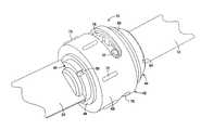
- FIG. 1is a perspective view of a preferred embodiment of the clamping apparatus shown with a blade inserted in the apparatus in its clamped position;
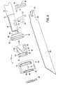
- FIG. 2is an exploded perspective illustrating the components of the apparatus shown in FIG. 1 ;
- FIG. 3is a cross-section taken generally along a line perpendicular to the orientation of the slot of the spindle at a location through the center of a detent pin;
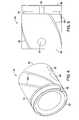
- FIG. 4is a perspective view of the sleeve of the apparatus shown in FIG. 1 ;
- FIG. 5is a side view of the sleeve of the apparatus shown in FIGS. 1 and 4 ;
- FIG. 6is a perspective view of the collar of the apparatus shown in FIG. 1 ;
- FIG. 7is another perspective view of the collar shown in the FIGS. 1 and 6 .
- clamping apparatusis certainly susceptible for use in applications other than these. It is contemplated that the clamping apparatus may be used in the medical field, particular with surgical instruments that are used with reciprocal saw and cutting blades. Also, while the embodiments of the present invention are particularly suited for use with power hand tools, they could be used with a non-power hand tool as well as larger stationary power tools that employ tool attachments in a reciprocating manner and where such tool attachments are replaced. The detailed description of the preferred embodiments are described with regard to saber and reciprocating saws which use commercially available saw blades. The present invention should not be limited to the described applications.
- the embodiments of the clamping apparatus of the present inventionare particularly suited for use with a saber saw which has a generally cylindrical plunger rod or spindle, although spindles or structure may be utilized which are other than the circular cross-section. However, if it is other than a circular cross-section throughout a significant part of its length, the spindle necessarily requires a generally cylindrical distal end portion in which the embodiments of the present invention are installed.
- the blade described herein in which the clamping mechanism of the embodiments of the present invention are to be usedis of conventional design for saber saw blades, but it should be understood that the various embodiments could be modified to operate with other styles of blades if desired.
- the preferred embodiments of the present inventionexhibit reliable operation and are not adversely affected by particulate contamination, such as dust from wood, plaster and drywall or metal particles that are often produced in significant quantities during use. It is also effective to retain the blade in jam situations or when scroll cutting which often applies side and twisting forces to the blade.
- the clean designalso utilizes a small number of parts and has a relatively low weight of the assembly which is desirable in order to minimize vibrations.
- a tool-less locking mechanismis indicated generally at 10 that has a relatively few number of parts that collaborate with a reciprocating spindle or plunger that is part of a reciprocating tool such as a jigsaw or reciprocating saw that is not shown in the drawings.
- the spindle 12has a preferably cylindrical shape with a slightly reduced diameter front portion 14 that forms an annular shoulder 16 .
- the front portion 14has an axially oriented slot 18 that is configured to receive a blade such as blade 20 .
- the blade 20has a shank portion 22 that has a hole 24 which the mechanism 10 engages to retain the blade in the slot 18 of the spindle 12 .
- the shank portionhas an elongated extension 26 which is helpful to hold the blade 20 at a constant angle in the slot 18 when the mechanism is in a clamped position.
- the front portion 14has an aperture 28 that extends from the near side of the spindle to the slot 18 , and may extend completely through the entire spindle if desired. However, it is preferred that the aperture extending to the other side of the slot 18 have a reduced diameter as shown in FIG. 3 so that the a detent pin 34 cannot fall through the other side. Alternatively, the other side of the slot could merely have a recess of sufficient depth that it would securely hold the blade 20 as shown in FIG. 3 .
- a second aperture 30is also provided and it extends completely through the entire spindle and is sized to receive a roll or solid pin 32 that is force fit therein when the mechanism is finally assembled.
- the aperture 28is sized to receive a detent pin 34 , which is slidable in the aperture 28 and has a truncated conical inner end portion 36 as best shown in FIG. 3 .
- the detent pin 34is sized so that the conical end portion 36 will penetrate into the aperture 24 and engage the blade 20 .
- the opposite end of the detent pin 34preferably has a slightly rounded surface 38 .
- the mechanism 10also has a sleeve, indicated generally at 40 , a rotatable collar, indicated generally at 42 , a cover, indicated generally at 44 , a spring, indicated generally at 46 , and in some of the embodiments also a clip 48 .
- Embodiments of the mechanismmay not include the cover 44 , inasmuch as it is an aesthetic component that does not perform an important operational function.
- the sleeve 40also has an aperture 50 and a second smaller aperture 52 .
- the aperture 50is substantially the same size as the aperture 28 of the spindle portion 14 , but may be slightly larger if desired.
- the aperture 52is substantially the same size as the aperture 30 in the spindle front portion 14 , but it too may be slightly larger if desired. It is important that the aperture 50 be sized to enable the detent pin 34 to slide within it and the aperture 52 must be sufficiently large that the roll pin 32 may be inserted into it.
- the inside diameter of the sleeve 40be substantially the same size as the front portion 14 of the spindle 12 and in fact may be slightly smaller than the diameter. It is preferred that the sleeve 40 be pressed onto the front portion 14 and if it is slightly smaller than the diameter of this front portion 14 , it will slightly narrow the width of the slot 18 by flexing the two sides together and thereby control the width of the blade gap or slot 18 . If the size of the apertures 52 are substantially the same size as the aperture 30 , then the roll pin 32 will engage the sleeve 40 on opposite sides. Since the sleeve 40 is preferably press fit on the spindle front portion 14 , the extreme front edge is preferably chamfered or otherwise rounded to more easily assemble the cover as well as the sleeve 40
- the sleeve 40may include an annular recess 54 that has a width preferably slightly larger than the thickness of the clip 48 so that the clip can be installed in the recess 54 .
- the recess 54may not be present.
- the preferred embodiments of the mechanismalso have a plurality of spiral grooves 58 in the outer surface of the sleeve 40 . While there are four of such grooves 58 shown in the drawings, it should be understood that a greater or lesser number of grooves can be provided. It is also contemplated that the grooves may not have the spiral angle as shown, but may be at a different angle, including a 0 degree angle (parallel to the axis of the sleeve 40 ) or a 90 degree angle or they may intersect one another. Also, as is best shown in FIGS. 4 and 5 , the spiral grooves 58 extend from the annular groove 54 rearwardly to the back end surface 60 .
- the groovesmay desirably extend from the front surface 62 to the rear surface 60 so that during operation, dust can be more effectively expelled from the front of the sleeve.
- the groovescan also have a width greater than that shown and may be somewhat deeper as well. It is preferred that the depth and width not be excessive relative to the thickness of the sleeve itself so as to compromise its structural rigidity and strength.
- the groovesare provided to improve the reliability of operation of the mechanism in an environment that produces large amounts of dust, such as dust or particulate material and the like.
- the collar 42When the collar 42 is rotated during insertion of the blade 20 in the slot 18 , the rotating movement of the collar will move dust particles into the grooves 58 .
- the reciprocating movement of the spindle 12When the tool is operated, the reciprocating movement of the spindle 12 will eject the dust particles from the grooves 58 and the blade holder mechanism thereby achieves a self-cleaning capability.
- Such self-cleaning capabilitymay be improved by embodiments that do not include the clip 48 .
- the collar 42is designed and configured to fit over the sleeve 40 , with an inside surface 64 being slightly larger than the outside surface of the sleeve 40 .
- the collar 42has an inner member 66 which is preferably made of steel or other strong material and also has an outer layer 68 that is preferably made of a resilient material such as rubber, plastic or other flexible material.
- the outer layer 68has a number of raised ribs 70 that provide a gripping surface for a user. Alternatively, recesses rather than ribs may be formed in the outer layer 68 .
- the inner member 66has an aperture 72 that is sized and configured to receive an axially oriented end 74 of the spring 46 , an opposite end 76 of the spring being perpendicular to the end 74 and being inwardly directed relative to the coils of the spring so that it will fit within the end of the slot 18 .
- the collar 42is rotatable on the sleeve 40 and it has a pair of opposed slots 78 that extend through an angular arc of approximately 60-90°. These slots 78 are sized to receive respective ends of the roll pin 32 .
- the roll pin 32has a length so that it extends slightly beyond the inner member 66 but does not extend beyond the outer surface of the outer layer 68 .
- the roll pin 32that extends through the entire assembly, provides limits for the collar rotation and securely mounts the mechanism to the spindle 12 .
- the inner member 66also has a cam surface 80 that gradually changes from the center axis of rotation from a maximum radius at location 82 to a minimum radius at location 84 .
- the cam surfaceis axially positioned on the collar 42 so that it is positioned to contact the rounded end 38 of the detent pin 34 .
- the fact that the roll pin 32 extends through both sides of the collar 42provides added stability to the cam surface 80 controlling the detent pin 34 .
- the spring 46is a torsion spring and it is twisted relative to the end 76 so that when the end 74 is placed in the aperture 72 a biasing force is produced which tends to move collar toward its clamped position, i.e., counterclockwise as shown in FIG. 6 .
- the roll pin 32effectively retains the collar 42 in place in an axial direction, even though it is free to rotate through the arc defined by the slots 78 .
- the clip 48can be employed.
- the illustrated mechanismalso includes the cover 44 which has an outer conical shaped portion 86 , an end portion 88 having an outer surface that engages the shoulder 16 of the spindle 12 and an inner portion 90 that has a diameter approximating the outside diameter of the reduced front portion 14 . It is hollow inside and fits around the spring 46 . The outside diameter of a front end portion 92 is slightly less than the diameter of the inner member 66 of the collar 42 .
- the cover 44also has a slot 94 through which the spring end can pass to enter the slot 18 of the spindle front portion 14 .
- the materials from which the present apparatus are madeis preferably steel or other hard metal, with the exception that the spring retainers do not normally experience excessive stresses and therefore may be fabricated from plastic or plastic-like material.
Landscapes
- Engineering & Computer Science (AREA)
- Mechanical Engineering (AREA)
- Sawing (AREA)
Abstract
Description
Claims (21)
Priority Applications (1)
| Application Number | Priority Date | Filing Date | Title |
|---|---|---|---|
| US12/151,176US8181973B2 (en) | 2008-05-05 | 2008-05-05 | Clamping apparatus for a reciprocating tool |
Applications Claiming Priority (1)
| Application Number | Priority Date | Filing Date | Title |
|---|---|---|---|
| US12/151,176US8181973B2 (en) | 2008-05-05 | 2008-05-05 | Clamping apparatus for a reciprocating tool |
Publications (2)
| Publication Number | Publication Date |
|---|---|
| US20090273146A1 US20090273146A1 (en) | 2009-11-05 |
| US8181973B2true US8181973B2 (en) | 2012-05-22 |
Family
ID=41256598
Family Applications (1)
| Application Number | Title | Priority Date | Filing Date |
|---|---|---|---|
| US12/151,176Expired - Fee RelatedUS8181973B2 (en) | 2008-05-05 | 2008-05-05 | Clamping apparatus for a reciprocating tool |
Country Status (1)
| Country | Link |
|---|---|
| US (1) | US8181973B2 (en) |
Cited By (10)
| Publication number | Priority date | Publication date | Assignee | Title |
|---|---|---|---|---|
| KR101440815B1 (en)* | 2012-12-28 | 2014-09-23 | 주식회사 다인정공 | Holder unit for installing tap adapter unit and holder unit-tap adapter unit assembly having the same |
| US20160214243A1 (en)* | 2013-10-21 | 2016-07-28 | Shanghai Easy-Use Tools Enterprise Co., Ltd | Rotary clamping mechanism and methods for using the same |
| US9545699B2 (en) | 2012-02-03 | 2017-01-17 | Makita Corporation | Work tool |
| US20170361428A1 (en)* | 2016-06-21 | 2017-12-21 | Globe Food Equipment Company | Blade mounting and removal tool, system, and product slicer |
| US11045939B2 (en) | 2018-03-28 | 2021-06-29 | Makita Corporation | Power tool |
| US11364545B2 (en) | 2019-12-26 | 2022-06-21 | Makita Corporation | Power tool |
| US11590593B2 (en) | 2019-11-28 | 2023-02-28 | Makita Corporation | Power tool |
| US11660690B2 (en) | 2019-11-28 | 2023-05-30 | Makita Corporation | Power tool |
| US11738397B2 (en) | 2019-06-12 | 2023-08-29 | Black & Decker Inc. | Reciprocating saw |
| US11772171B2 (en) | 2020-02-13 | 2023-10-03 | Makita Corporation | Power tool |
Families Citing this family (18)
| Publication number | Priority date | Publication date | Assignee | Title |
|---|---|---|---|---|
| US7871080B2 (en)* | 2004-01-16 | 2011-01-18 | Robert Bosch Gmbh | Tool-less blade clamping apparatus for a reciprocating tool |
| CN101676055B (en)* | 2008-09-19 | 2011-09-21 | 车王电子股份有限公司 | Knife saw joint for knife saw machine |
| US8292150B2 (en) | 2010-11-02 | 2012-10-23 | Tyco Healthcare Group Lp | Adapter for powered surgical devices |
| US8801713B2 (en)* | 2011-04-07 | 2014-08-12 | DePuy Synthes Products, LLC | Surgical drill instrument with motor and locking mechanism to receive an attachment and a cutting burr |
| US8690876B2 (en) | 2011-04-07 | 2014-04-08 | DePuy Synthes Products, LLC | Cutting burr shank configuration |
| DE102011075228B4 (en)* | 2011-05-04 | 2025-02-06 | Robert Bosch Gmbh | oscillating tool clamping device |
| WO2013020115A2 (en) | 2011-08-04 | 2013-02-07 | Milwaukee Electric Tool Corporation | Reciprocating saw blade |
| US8641336B1 (en)* | 2011-08-12 | 2014-02-04 | Charles A. Van Horssen | Tool holder and cutting tool |
| CN103203497B (en)* | 2012-01-16 | 2017-05-03 | 博世电动工具(中国)有限公司 | Saw blade clamping device |
| USD688543S1 (en) | 2012-03-20 | 2013-08-27 | Milwaukee Electric Tool Corporation | Saw blade |
| USD687275S1 (en) | 2012-03-20 | 2013-08-06 | Milwaukee Electric Tool Corporation | Saw blade |
| US9156097B2 (en) | 2012-03-20 | 2015-10-13 | Milwaukee Electric Tool Corporation | Reciprocating saw blade clamp |
| USD729600S1 (en) | 2014-05-06 | 2015-05-19 | Milwaukee Electric Tool Corporation | Saw blade |
| US9839425B2 (en) | 2014-06-26 | 2017-12-12 | Covidien Lp | Adapter assembly for interconnecting electromechanical surgical devices and surgical loading units, and surgical systems thereof |
| US10333459B2 (en) | 2016-09-01 | 2019-06-25 | Sunpower Corporation | Photovoltaic module mounting assembly having a pin constraint |
| CN111579002B (en)* | 2020-06-05 | 2020-11-10 | 武义义蓝日用金属制品有限公司 | A metal characteristic analysis device |
| CN111940834B (en)* | 2020-07-09 | 2025-04-22 | 浙江亚特电器股份有限公司 | A chain saw with rapid braking |
| US11862884B2 (en) | 2021-08-16 | 2024-01-02 | Covidien Lp | Surgical instrument with electrical connection |
Citations (14)
| Publication number | Priority date | Publication date | Assignee | Title |
|---|---|---|---|---|
| US3583716A (en)* | 1969-02-06 | 1971-06-08 | Singer Co | Chuck assembly for power tools |
| US3823473A (en)* | 1970-11-09 | 1974-07-16 | S Hoffman | Blade attachment means for saber saw assembly |
| US4020555A (en)* | 1976-04-12 | 1977-05-03 | Pevrick Engineering Co., Inc. | Connecting mechanism for a saw blade |
| US4502824A (en)* | 1978-03-16 | 1985-03-05 | Robert Bosch Gmbh | Tool chuck |
| US5566595A (en)* | 1993-08-24 | 1996-10-22 | Socket Retainer Systems, Inc. | Socket mounting arrangement |
| US6209208B1 (en)* | 1998-10-09 | 2001-04-03 | Milwaukee Electric Tool Corporarion | Keyless blade clamp mechanism |
| US6612039B2 (en)* | 2000-05-16 | 2003-09-02 | Makita Corporation | Blade mounting devices |
| US6725548B1 (en)* | 1996-03-01 | 2004-04-27 | Milwaukee Electric Tool Corporation | Keyless blade clamp mechanism |
| US20040194324A1 (en) | 2003-04-07 | 2004-10-07 | Liao Youn-Chyuan | Tool head fixer |
| US6851194B1 (en)* | 2003-10-06 | 2005-02-08 | Motomax Electric Co., Ltd. | Reciprocating saw having a blade holding device |
| US6863280B2 (en)* | 2002-11-20 | 2005-03-08 | Li Jiun Chiu | Tool fixing structure |
| US20050156390A1 (en)* | 2004-01-16 | 2005-07-21 | Credo Technology Corporation | Tool-less blade clamping apparatus for a reciprocating tool |
| US7040023B2 (en) | 2002-11-25 | 2006-05-09 | Eastway Fair Company Limited | Toolless blade holder for a reciprocating tool |
| US7251897B2 (en) | 2003-04-14 | 2007-08-07 | Positec Power Tools (Suzhou) Co., Ltd. | Blade clamping device |
- 2008
- 2008-05-05USUS12/151,176patent/US8181973B2/ennot_activeExpired - Fee Related
Patent Citations (15)
| Publication number | Priority date | Publication date | Assignee | Title |
|---|---|---|---|---|
| US3583716A (en)* | 1969-02-06 | 1971-06-08 | Singer Co | Chuck assembly for power tools |
| US3823473A (en)* | 1970-11-09 | 1974-07-16 | S Hoffman | Blade attachment means for saber saw assembly |
| US4020555A (en)* | 1976-04-12 | 1977-05-03 | Pevrick Engineering Co., Inc. | Connecting mechanism for a saw blade |
| US4502824A (en)* | 1978-03-16 | 1985-03-05 | Robert Bosch Gmbh | Tool chuck |
| US5566595A (en)* | 1993-08-24 | 1996-10-22 | Socket Retainer Systems, Inc. | Socket mounting arrangement |
| US6725548B1 (en)* | 1996-03-01 | 2004-04-27 | Milwaukee Electric Tool Corporation | Keyless blade clamp mechanism |
| US6209208B1 (en)* | 1998-10-09 | 2001-04-03 | Milwaukee Electric Tool Corporarion | Keyless blade clamp mechanism |
| US6612039B2 (en)* | 2000-05-16 | 2003-09-02 | Makita Corporation | Blade mounting devices |
| US20040035010A1 (en) | 2000-05-16 | 2004-02-26 | Makita Corporation | Blade mounting devices |
| US6863280B2 (en)* | 2002-11-20 | 2005-03-08 | Li Jiun Chiu | Tool fixing structure |
| US7040023B2 (en) | 2002-11-25 | 2006-05-09 | Eastway Fair Company Limited | Toolless blade holder for a reciprocating tool |
| US20040194324A1 (en) | 2003-04-07 | 2004-10-07 | Liao Youn-Chyuan | Tool head fixer |
| US7251897B2 (en) | 2003-04-14 | 2007-08-07 | Positec Power Tools (Suzhou) Co., Ltd. | Blade clamping device |
| US6851194B1 (en)* | 2003-10-06 | 2005-02-08 | Motomax Electric Co., Ltd. | Reciprocating saw having a blade holding device |
| US20050156390A1 (en)* | 2004-01-16 | 2005-07-21 | Credo Technology Corporation | Tool-less blade clamping apparatus for a reciprocating tool |
Cited By (16)
| Publication number | Priority date | Publication date | Assignee | Title |
|---|---|---|---|---|
| US9545699B2 (en) | 2012-02-03 | 2017-01-17 | Makita Corporation | Work tool |
| US10144110B2 (en) | 2012-02-03 | 2018-12-04 | Makita Corporation | Work tool |
| KR101440815B1 (en)* | 2012-12-28 | 2014-09-23 | 주식회사 다인정공 | Holder unit for installing tap adapter unit and holder unit-tap adapter unit assembly having the same |
| US20160214243A1 (en)* | 2013-10-21 | 2016-07-28 | Shanghai Easy-Use Tools Enterprise Co., Ltd | Rotary clamping mechanism and methods for using the same |
| US10195725B2 (en)* | 2013-10-21 | 2019-02-05 | Shanghai Easy-Use Tools Enterprise Co., Ltd | Rotary clamping mechanism and methods for using the same |
| US20170361428A1 (en)* | 2016-06-21 | 2017-12-21 | Globe Food Equipment Company | Blade mounting and removal tool, system, and product slicer |
| US10589439B2 (en)* | 2016-06-21 | 2020-03-17 | Globe Food Equipment Company | Blade mounting and removal tool, system, and product slicer |
| US11045939B2 (en) | 2018-03-28 | 2021-06-29 | Makita Corporation | Power tool |
| US11759873B2 (en) | 2019-06-12 | 2023-09-19 | Black & Decker Inc. | Reciprocating saw |
| US11738397B2 (en) | 2019-06-12 | 2023-08-29 | Black & Decker Inc. | Reciprocating saw |
| US11590593B2 (en) | 2019-11-28 | 2023-02-28 | Makita Corporation | Power tool |
| US11660690B2 (en) | 2019-11-28 | 2023-05-30 | Makita Corporation | Power tool |
| US12290868B2 (en) | 2019-11-28 | 2025-05-06 | Makita Corporation | Power tool |
| US12290867B2 (en) | 2019-11-28 | 2025-05-06 | Makita Corporation | Power tool |
| US11364545B2 (en) | 2019-12-26 | 2022-06-21 | Makita Corporation | Power tool |
| US11772171B2 (en) | 2020-02-13 | 2023-10-03 | Makita Corporation | Power tool |
Also Published As
| Publication number | Publication date |
|---|---|
| US20090273146A1 (en) | 2009-11-05 |
Similar Documents
| Publication | Publication Date | Title |
|---|---|---|
| US8181973B2 (en) | Clamping apparatus for a reciprocating tool | |
| EP1555078B1 (en) | Tool-less blade clamping apparatus for a reciprocating tool | |
| EP1745889B1 (en) | Accessory for a rotary tool | |
| US9067293B2 (en) | Accessory clamp for a power tool | |
| GB2483008A (en) | Removable cutting blade comprising locking surface between first and second cutting edges | |
| US20250214160A1 (en) | Blade clamp for reciprocating saw | |
| GB2398540A (en) | Hand saw | |
| EP0810050B1 (en) | Saw blade clamping arrangement for a power tool | |
| WO2014014768A1 (en) | Collet fan for a rotary tool | |
| EP3765226B1 (en) | Blade clamp for power tool, reciprocating power tool, and method of operating such a blade clamp | |
| EP3538310A1 (en) | Blade clamp for a reciprocating power tool | |
| CA2874809C (en) | Collet retention mechanism for a rotary tool | |
| CA2874855C (en) | Collet positioning mechanism for a rotary tool | |
| CA2874868C (en) | Quick change collet chuck assembly and manufacturing thereof | |
| US9162293B2 (en) | Release mechanism for a rotary tool | |
| CN217492914U (en) | Multifunctional saw blade clamping device |
Legal Events
| Date | Code | Title | Description |
|---|---|---|---|
| AS | Assignment | Owner name:CREDO TECHNOLOGY CORPORATION, ILLINOIS Free format text:ASSIGNMENT OF ASSIGNORS INTEREST;ASSIGNORS:DEZHENG, ZHENG;MICHEL, TIMOTHY P.;KRONDORFER, HARALD;REEL/FRAME:020962/0456;SIGNING DATES FROM 20071221 TO 20080107 Owner name:ROBERT BOSCH GMBH, GERMANY Free format text:ASSIGNMENT OF ASSIGNORS INTEREST;ASSIGNORS:DEZHENG, ZHENG;MICHEL, TIMOTHY P.;KRONDORFER, HARALD;REEL/FRAME:020962/0456;SIGNING DATES FROM 20071221 TO 20080107 Owner name:CREDO TECHNOLOGY CORPORATION, ILLINOIS Free format text:ASSIGNMENT OF ASSIGNORS INTEREST;ASSIGNORS:DEZHENG, ZHENG;MICHEL, TIMOTHY P.;KRONDORFER, HARALD;SIGNING DATES FROM 20071221 TO 20080107;REEL/FRAME:020962/0456 Owner name:ROBERT BOSCH GMBH, GERMANY Free format text:ASSIGNMENT OF ASSIGNORS INTEREST;ASSIGNORS:DEZHENG, ZHENG;MICHEL, TIMOTHY P.;KRONDORFER, HARALD;SIGNING DATES FROM 20071221 TO 20080107;REEL/FRAME:020962/0456 | |
| ZAAA | Notice of allowance and fees due | Free format text:ORIGINAL CODE: NOA | |
| ZAAB | Notice of allowance mailed | Free format text:ORIGINAL CODE: MN/=. | |
| STCF | Information on status: patent grant | Free format text:PATENTED CASE | |
| FPAY | Fee payment | Year of fee payment:4 | |
| MAFP | Maintenance fee payment | Free format text:PAYMENT OF MAINTENANCE FEE, 8TH YEAR, LARGE ENTITY (ORIGINAL EVENT CODE: M1552); ENTITY STATUS OF PATENT OWNER: LARGE ENTITY Year of fee payment:8 | |
| FEPP | Fee payment procedure | Free format text:MAINTENANCE FEE REMINDER MAILED (ORIGINAL EVENT CODE: REM.); ENTITY STATUS OF PATENT OWNER: LARGE ENTITY | |
| LAPS | Lapse for failure to pay maintenance fees | Free format text:PATENT EXPIRED FOR FAILURE TO PAY MAINTENANCE FEES (ORIGINAL EVENT CODE: EXP.); ENTITY STATUS OF PATENT OWNER: LARGE ENTITY | |
| STCH | Information on status: patent discontinuation | Free format text:PATENT EXPIRED DUE TO NONPAYMENT OF MAINTENANCE FEES UNDER 37 CFR 1.362 | |
| FP | Lapsed due to failure to pay maintenance fee | Effective date:20240522 |