US8181543B2 - CVS system sample water vapor management - Google Patents
CVS system sample water vapor managementDownload PDFInfo
- Publication number
- US8181543B2 US8181543B2US12/501,767US50176709AUS8181543B2US 8181543 B2US8181543 B2US 8181543B2US 50176709 AUS50176709 AUS 50176709AUS 8181543 B2US8181543 B2US 8181543B2
- Authority
- US
- United States
- Prior art keywords
- sample
- gas
- fill gas
- fill
- test procedure
- Prior art date
- Legal status (The legal status is an assumption and is not a legal conclusion. Google has not performed a legal analysis and makes no representation as to the accuracy of the status listed.)
- Active, expires
Links
Images


Classifications
- G—PHYSICS
- G01—MEASURING; TESTING
- G01N—INVESTIGATING OR ANALYSING MATERIALS BY DETERMINING THEIR CHEMICAL OR PHYSICAL PROPERTIES
- G01N1/00—Sampling; Preparing specimens for investigation
- G01N1/02—Devices for withdrawing samples
- G01N1/22—Devices for withdrawing samples in the gaseous state
- G01N1/2247—Sampling from a flowing stream of gas
- G01N1/2252—Sampling from a flowing stream of gas in a vehicle exhaust
- G—PHYSICS
- G01—MEASURING; TESTING
- G01M—TESTING STATIC OR DYNAMIC BALANCE OF MACHINES OR STRUCTURES; TESTING OF STRUCTURES OR APPARATUS, NOT OTHERWISE PROVIDED FOR
- G01M15/00—Testing of engines
- G01M15/04—Testing internal-combustion engines
- G01M15/10—Testing internal-combustion engines by monitoring exhaust gases or combustion flame
- G01M15/102—Testing internal-combustion engines by monitoring exhaust gases or combustion flame by monitoring exhaust gases
- G—PHYSICS
- G01—MEASURING; TESTING
- G01N—INVESTIGATING OR ANALYSING MATERIALS BY DETERMINING THEIR CHEMICAL OR PHYSICAL PROPERTIES
- G01N1/00—Sampling; Preparing specimens for investigation
- G01N1/02—Devices for withdrawing samples
- G01N1/22—Devices for withdrawing samples in the gaseous state
- G01N1/2247—Sampling from a flowing stream of gas
- G01N1/2252—Sampling from a flowing stream of gas in a vehicle exhaust
- G01N2001/2255—Sampling from a flowing stream of gas in a vehicle exhaust with dilution of the sample
- G—PHYSICS
- G01—MEASURING; TESTING
- G01N—INVESTIGATING OR ANALYSING MATERIALS BY DETERMINING THEIR CHEMICAL OR PHYSICAL PROPERTIES
- G01N1/00—Sampling; Preparing specimens for investigation
- G01N1/02—Devices for withdrawing samples
- G01N1/22—Devices for withdrawing samples in the gaseous state
- G01N1/2247—Sampling from a flowing stream of gas
- G01N2001/2264—Sampling from a flowing stream of gas with dilution
Definitions
- CVSconstant volume samplers
- engine exhaustis diluted with ambient air, and a small sample of the diluted exhaust is proportionally extracted and stored in one or more sample bags.
- the CVS total flow ratewhich includes both ambient air and engine exhaust, is selected to ensure the sample collected does not condense water when stored in the bags, or during subsequent analysis. This flow rate is determined by calculating the average dew point in the bag sample.
- condensation of waterimpacts the accuracy of the exhaust analysis. Some substances in the exhaust become soluble in water. These substances can be effectively “pulled out” of the exhaust so that they are not measured at the conclusion of the test. Also, the water vapor that becomes condensed is not measured and included in the test results. Second, the condensation can cause the collection of substances on the inside of the bag as the water subsequently evaporates thereby leaving an undesirable residue that will be present during future tests. Finally, new legislation requires no condensation in the sample bags.
- the cycleis 600 seconds long and the second sample bag used in the test will start filling 133 seconds into the drive cycle.
- the traditional desired flow rateis 1050 scfm when diluting a gas with a dew point of 18 deg C.
- the ending dew point in the bagwill be just above 23 deg C., with a peak dew point at the beginning of the second bag fill of 27 deg C. This is often higher than ambient conditions in a test cell.
- the CVS flow ratewould typically be selected to dilute for the average bag dew point of 23 deg C., which would result in the sample condensing in the second sample bag due to the initial high peak.
- the CVS flow rateIn order to avoid condensation in the bag, the CVS flow rate would have to be raised to 2000 scfm to avoid the initial peak, which is undesirable. Increasing the CVS flow rate would reduce the already low concentration of exhaust within the sample making it more difficult to analyze.
- One approach that can be used to avoid condensationis to heat the bags, which would maintain the sample gas temperature above the maximum dew point and avoid the initial dew point peak.
- additional equipmentmust be employed for such an approach leading to a higher cost CVS.
- Current test proceduresrequire bag sampling using either a CVS method or a bag mini-diluter (BMD) method.
- Hybrid vehicles that produce exhaust gas from internal combustion enginesmay not be in operation or may operate for a brief period of time over the test cycle.
- CVS methodthe CVS bag sample is overdiluted and determination of mass emissions is difficult since the dilution factor from the CVS method is very high.
- BMD methodthe bag sample is diluted at a fixed rate so the dilution factor issue is resolved but the sample is collected proportional to the exhaust flow. Since there are periods of operation where either no exhaust flow is expelled out of the hybrid vehicle or the vehicle exhaust is expelled intermittently very little exhaust may be emitted during the sample phase. Therefore, very little sample will be collected in the sample bag making accurate analysis more difficult.
- a disclosed method of collecting an exhaust gas sampleincludes pre-filling a sample bag with a pre-fill gas. An exhaust sample is collected in the sample bag with the pre-fill gas remaining in the sample bag.
- An exhaust sampling systemincludes a pre-fill gas source having a pre-fill gas.
- a sampling conduitis configured to collect exhaust gas and make-up gas.
- a sample bagis fluidly connected to the sampling conduit and the pre-fill gas source.
- a controlleris programmed to run a test procedure in which a sample of exhaust gas and make-up gas is collected in the sample bag. The controller is configured to send a command that fills the sample bag with pre-fill gas prior to the test procedure. The pre-fill gas remains in the sample bag during the test procedure.
- the amount of pre-fill gasis selected to prevent the sample from condensing in the sample bag during the test procedure.
- the amount of pre-fill gasis selected to provide a sufficient volume of gases for analysis during the test procedure.
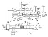
- FIG. 1is a schematic view of an example CVS including an example pre-fill gas system.
- FIG. 2is a flow chart depicting an example pre-fill procedure.
- FIG. 3is a schematic view of an example BMD including an example pre-fill gas system.
- FIG. 4is a flow chart depicting an example pre-fill procedure.
- FIG. 1A schematic view of an exhaust sampling system 10 is shown in FIG. 1 .
- the system 10includes a make-up air inlet 12 that includes a filter 14 .
- the inlet 12provides make-up air 32 to a sampling conduit that also receives exhaust from a tailpipe 16 of an engine 18 .
- the make-up air 32 and exhaust Epass through a mixing plate 20 to promote homogeneous mixing of the make-up air 32 and exhaust E as it flows through a tunnel 22 prior to sampling.
- a constant volume of the mixtureis drawn through the sampling conduit by a pump 28 .
- a heat exchanger 24is used, in one example, to maintain the mixture at a desired temperature.
- the mixtureis measured by a measuring device 26 , prior to being expelled by the pump 28 through a discharge 30 , to determine the quantity of mixture flowing through the sampling conduit. It should be understood that the system 10 is only exemplary and that many modifications can be made and still fall within the scope of the claims.
- the engine 18is run through a test procedure to determine the quantity of exhaust byproducts that the engine 18 produces. For the example system 10 shown, only a small portion of the exhaust E is sampled for subsequent analysis. As the amount of exhaust E produced by the engine 18 during the test procedure fluctuates, the make-up air 32 provides the remainder of the volume. The amount of byproducts in the sample is so small at times, that the components in the make-up air can impact the test results. To this end, a pump 34 draws an amount of make-up air into background bags 42 during the test procedure so that the effects of the make-up air can be taken into account. Valves 36 , 40 regulate the flow of make-up air 32 into the background bags 42 , and the flow meter 38 measures the amount of make-up air collected within the background bags 42 .
- a sampler 43collects a small sample of the mixture for collecting into sample bags 52 .
- One or more sample bags 52may be used, and filling of the sample bags may be scheduled during various periods of the test procedure.
- a pump 44draws the sample through a valve 46 and flow meter 48 .
- Valves 50regulate the filling of the sample bags 52 .
- an analyzer 60analyzes the contents of the sample bags 52 and 42 to determine the amount of various combustion byproducts.
- a pump 54flows the sample through valve 56 and flow meter 58 . It should be understood that more or fewer pumps, valves and flow meters than shown could be used.
- a controller 70communicates during the test procedure with the various pumps 28 , 34 , 54 , 64 , 72 , valves 36 , 40 46 , 50 , 56 , 66 , 74 and flow meters 38 , 48 , 58 , 68 to obtain readings and direct their operation. All of the connections between the controller 70 and these components are not shown for clarity.
- one or more of the sample bags 52is pre-filled with dry gas to prevent any peaks in dew point during the test procedure that would lead to undesired condensation.
- a source of pre-fill gas 62is shown schematically in FIG. 1 .
- An amount of pre-fill gasis pumped into one or more of the sample bags 52 prior to the collection of the exhaust sample.
- the controller 70commands the pump 64 and valve 66 to fill a desired amount of pre-fill gas to a desired sample bag 52 to prevent condensation in the sample bag 52 .
- the pre-fillmay also incorporate other means to fill the bag such as a compressed air source.
- the flow meter 68measures the amount of pre-fill gas.
- An example test procedure 78 according to the disclosureis shown in FIG. 2 .
- the amount of pre-fill gas needed to prevent condensationis calculated at block 84 based upon one or more of the following (indicated at block 86 ): CVS test flow rate, dew point of the pre-fill gas, dew point of the make-up air, and anticipated test dew point within the sample bag 52 . Calculations are performed based upon the various factors of each test to determine the minimum amount of pre-fill gas required to avoid condensation. This approach is desirable to minimize further dilution of the sample.
- the bags susceptible to condensationwould be filled with dry clean air prior to the sampling (filling of the bag). According to this disclosure, the initial peak of wet gas is compensated for by the dry air, thus preventing condensation.
- the sample bags 52 and ambient bags 42are evacuated through vent 74 using pump 72 ( FIG. 1 ), as indicated at block 80 .
- the system 10is leak checked (block 82 ), and the sample bag 52 is filled with a predetermined amount of pre-fill gas, as indicated at block 88 .
- the amount of pre-fill gasis measured.
- the exhaust sampleis collected and its mass and/or volume measured in the sample bag 52 during the test procedure with the pre-fill gas remaining in the sample bag 52 , as indicated at block 92 .
- the dew point of the predetermined amount of pre-fill gasprevents the exhaust sample from condensing within the sample bag 52 .
- the contents of the sample bag 52 and ambient bag 42can then be analyzed to determine the amount of byproducts within the sample, as indicated at block 94 .
- the same “zero grade” or “instrument grade” air that is typically used to initially calibrate the system 10can be used to pre-fill the sample bag 52 .
- the pre-fill featurecan be incorporated into a traditional CVS with very little modification and expense.
- ambient aircan be used to pre-fill the sample bag 52 .
- ambient airmay be desirable since it makes accounting for the pre-fill air's affects at the analysis stage of the test simpler.
- the analytical equations set forth in the Code of Federal Regulations for test proceduresare such that accounting for pre-fill ambient air is more straightforward.
- Using zero grade air instead of ambient airrequires modifications to those equations, which may be undesired by some customers. For example, using zero air requires using dilution ratio equations similar to those used for a BMD to determine the concentration necessary to use traditional CVS equations. It should be understood that any number of suitable substances may be used to pre-fill the sample bags 52 .
- FIG. 3A schematic view of another exhaust sampling system 110 is shown in FIG. 3 .
- the system 110illustrates a BMD sampling system in which the exhaust sample is diluted at a fixed rate and the exhaust gas sample is collected in proportion to the exhaust flow from the engine 118 .
- the engine 118includes an internal combustion engine 96 and another engine 98 (such as an electric motor) that together comprise the propulsion unit for a hybrid vehicle.
- the other engine 98may be used to propel the vehicle in varying degrees throughout vehicle operation. As a result, there may be periods of operation when the engine 118 expels little or no exhaust through its tailpipe 116 when the other engine 98 is in use.
- the system 110includes a “mini-diluter” having a probe or sampler 143 .
- the sampler 143collects a small sample of exhaust gas from the tailpipe 116 .
- the sample exhaust gasis drawn into a sampling unit 102 by a pump 144 .
- the sampling unit 102includes a mixer 104 .
- a diluent 112is introduced to the sampling unit 102 at the mixer 104 where it commingles with the sample exhaust gas to produce a diluted exhaust gas that is supplied to a diluted exhaust gas outlet 108 .
- the diluent 112is nitrogen or zero air.
- the diluent 112is measured by a flowmeter 106 .
- the sample exhaust gas flowcorresponds to a difference between a total exhaust gas flow measured by a flowmeter 148 , which receives the diluted exhaust gas from the outlet 108 , and the flowmeter 106 .
- the exhaust gas sampleis measured directly by a flowmeter 141 .
- the engine 118is run through a test procedure to determine the quantity of exhaust byproducts that the engine 118 produces. For the example system 110 shown, only a small portion of the exhaust is sampled for subsequent analysis. As the amount of exhaust produced by the engine 118 during the test procedure fluctuates, the diluent 112 provides the remainder of the volume.
- the sampler 143collects a small sample of the mixture for collecting into sample bags 152 .
- One or more sample bags 152may be used, and filling of the sample bags may be scheduled during various periods of the test procedure.
- Valves 150regulate the filling of the sample bags 152 .
- an analyzer 160analyzes the contents of the sample bags 152 to determine the amount of various combustion byproducts.
- a pump 154flows the sample through valve 156 and flow meter 158 . It should be understood that more or fewer pumps, valves and flow meters than shown could be used.
- a controller 170communicates during the test procedure with the various pumps 128 , 154 , 164 , 172 , valves 150 , 156 , 174 and flow meters 106 , 148 , 158 to obtain readings and direct their operation. All of the connections between the controller 170 and these components are not shown for clarity.
- one or more of the sample bags 152is pre-filled with dry gas to provide a sufficient volume of gases in the bags 152 for subsequent analysis.
- a source of pre-fill gas 162is shown schematically in FIG. 3 .
- a common nitrogen sourcecan be used for both the diluent 112 and the pre-fill gas 162 .
- the pre-fill gas 162is nitrogen.
- An amount of pre-fill gasis pumped into one or more of the sample bags 152 prior to the collection of the exhaust sample.
- the controller 170commands the pump 164 to fill a desired amount of pre-fill gas to a desired sample bag 152 to sufficiently fill the sample bag 152 , discussed in more detail below.
- the pre-fillmay also incorporate other means to fill the bag such as a compressed air source.
- the flow meter 106measures the amount of pre-fill gas. Using the same flow meter 106 to measure the pre-fill gas and the diluent during the test procedure minimizes calibration error.
- the amount of pre-fill gas needed to provide a sufficient volume of gases in the bags 152is calculated at block 184 based upon one or more of the following (indicated at block 186 ): time for the sample to stabilize (time period for the sample to fully reach the analyzer 160 ), the flow rate of gases within the analytical system and the analysis time required.
- time for the sample to stabilizetime period for the sample to fully reach the analyzer 160
- the flow rate of gases within the analytical systemthe analysis time required.
- the amount of sample collected within the bags 152should be enough to provide the analytical system with approximately 3 minutes of analysis time. This is based upon the typical scenario in which a typical analysis by the analyzer 160 takes approximately 30 seconds to 1 minute.
- three or four analysesare conducted with the contents of a given bag 152 in connection with the steps described in relation to block 192 . Calculations are performed based upon the various factors of each test to determine the minimum amount of pre-fill gas required for analysis. Pre-filling one or more of the bags 152 is desirable to ensure that enough sample is available for analysis even if the hybrid vehicle produces no exhaust during the sampling period.
- the sample bags 152are evacuated through vent 174 using pump 172 ( FIG. 3 ), as indicated at block 180 .
- the system 110is leak checked (block 182 ), and the sample bag 152 is filled with a predetermined amount of pre-fill gas, as indicated at block 88 .
- the amount of pre-fill gasis measured.
- the exhaust sampleis collected and its mass and/or volume measured in the sample bag 152 during the test procedure with the pre-fill gas remaining in the sample bag 152 , as indicated at block 192 .
- the collect/measure sample step in block 192requires a sufficient volume of gases within each sample bag 152 in order to perform the measuring steps.
- the measuring stepsfirst includes “sniffing” the sample bag 152 to determine the concentration of byproducts that will be analyzed.
- the analyzer 160typically includes multiple analyzers, each corresponding to a different concentration range. A particular analyzer having a range corresponding to the “sniffed” range is selected for use in subsequent analysis of each byproduct in the contents of sample bag 152 .
- a calibration of the analytical systemis performed, including zeroing the instruments, which may be performed by flowing nitrogen through the instruments.
- an analysis of the contents of the sample bag 152is then performed to determine the amount of byproducts collected within the bag, such as carbon dioxide, carbon monoxide, hydrocarbons, and oxides of nitrogen. Finally, a zero check is performed to ensure that none of the instruments have drifted during the analysis. Any of the measuring steps above may be repeated if the system fails the calibration check.
- the system 10 and method 78 shown in FIGS. 1 and 2also employ the above collect/measure sample step in block 92 .
- the dilution ratiois measured as the ratio sample flow to total flow of the BMD and integrated over the test procedure.
- the dilution ratiointegrates the amount of dilution gas in a given bag 152 from the pre-filled process plus the amount of diluent used during the test procedure.
- the dilution ratio for the system 110is as follows (block 190 ):
- PrefillBagVol, DilutionVol and SampleVolrespectively correspond to the pre-fill gas, diluent and sample exhaust gas volumes relating to a given sample bag 152 .
- the contents of the sample bag 152 and ambient bag 142can then be analyzed to determine the amount of byproducts within the sample, as indicated at block 194 .
- the same “zero grade” or “instrument grade” air that is typically used to initially calibrate the system 110can be used to pre-fill the sample bag 152 .
- the pre-fill featurecan be incorporated into a traditional BMD with very little modification and expense.
- ambient aircan be used to pre-fill the sample bag 152 .
- ambient airmay be desirable since it makes accounting for the pre-fill air's affects at the analysis stage of the test simpler.
- the analytical equations set forth in the Code of Federal Regulations for test proceduresare such that accounting for pre-fill ambient air is more straightforward. Using zero grade air instead of ambient air requires modifications to those equations, which may be undesired by some customers. It should be understood, however, that any number of suitable substances may be used to pre-fill the sample bags 152 .
Landscapes
- Chemical & Material Sciences (AREA)
- Engineering & Computer Science (AREA)
- Combustion & Propulsion (AREA)
- Physics & Mathematics (AREA)
- General Physics & Mathematics (AREA)
- Health & Medical Sciences (AREA)
- Life Sciences & Earth Sciences (AREA)
- Biomedical Technology (AREA)
- Molecular Biology (AREA)
- Analytical Chemistry (AREA)
- Biochemistry (AREA)
- General Health & Medical Sciences (AREA)
- Immunology (AREA)
- Pathology (AREA)
- Sampling And Sample Adjustment (AREA)
Abstract
Description
where PrefillBagVol, DilutionVol and SampleVol respectively correspond to the pre-fill gas, diluent and sample exhaust gas volumes relating to a given
Claims (25)
Priority Applications (3)
| Application Number | Priority Date | Filing Date | Title |
|---|---|---|---|
| US12/501,767US8181543B2 (en) | 2006-09-15 | 2009-07-13 | CVS system sample water vapor management |
| US13/463,226US9097623B2 (en) | 2006-09-15 | 2012-05-03 | CVS system sample water vapor management |
| US14/816,304US10151670B2 (en) | 2006-09-15 | 2015-08-03 | CVS system sample water vapor management |
Applications Claiming Priority (3)
| Application Number | Priority Date | Filing Date | Title |
|---|---|---|---|
| US84527106P | 2006-09-15 | 2006-09-15 | |
| US11/855,246US7559262B2 (en) | 2006-09-15 | 2007-09-14 | CVS system sample water vapor management |
| US12/501,767US8181543B2 (en) | 2006-09-15 | 2009-07-13 | CVS system sample water vapor management |
Related Parent Applications (1)
| Application Number | Title | Priority Date | Filing Date |
|---|---|---|---|
| US11/855,246Continuation-In-PartUS7559262B2 (en) | 2006-09-15 | 2007-09-14 | CVS system sample water vapor management |
Related Child Applications (1)
| Application Number | Title | Priority Date | Filing Date |
|---|---|---|---|
| US13/463,226ContinuationUS9097623B2 (en) | 2006-09-15 | 2012-05-03 | CVS system sample water vapor management |
Publications (2)
| Publication Number | Publication Date |
|---|---|
| US20100000339A1 US20100000339A1 (en) | 2010-01-07 |
| US8181543B2true US8181543B2 (en) | 2012-05-22 |
Family
ID=41463319
Family Applications (3)
| Application Number | Title | Priority Date | Filing Date |
|---|---|---|---|
| US12/501,767Active2028-12-27US8181543B2 (en) | 2006-09-15 | 2009-07-13 | CVS system sample water vapor management |
| US13/463,226Active2028-12-01US9097623B2 (en) | 2006-09-15 | 2012-05-03 | CVS system sample water vapor management |
| US14/816,304Active2028-10-10US10151670B2 (en) | 2006-09-15 | 2015-08-03 | CVS system sample water vapor management |
Family Applications After (2)
| Application Number | Title | Priority Date | Filing Date |
|---|---|---|---|
| US13/463,226Active2028-12-01US9097623B2 (en) | 2006-09-15 | 2012-05-03 | CVS system sample water vapor management |
| US14/816,304Active2028-10-10US10151670B2 (en) | 2006-09-15 | 2015-08-03 | CVS system sample water vapor management |
Country Status (1)
| Country | Link |
|---|---|
| US (3) | US8181543B2 (en) |
Cited By (5)
| Publication number | Priority date | Publication date | Assignee | Title |
|---|---|---|---|---|
| CN104380077A (en)* | 2012-05-29 | 2015-02-25 | Avl测试系统公司 | Intelligent bag filling for exhaust sampling system |
| US9243983B2 (en) | 2010-04-09 | 2016-01-26 | Mark Guenther | Emissions test system and method |
| US9297726B2 (en) | 2012-05-23 | 2016-03-29 | Avl Test Systems, Inc. | Exhaust sampling system and method for water vapor management |
| US20170074145A1 (en)* | 2015-09-11 | 2017-03-16 | Avl Test Systems, Inc. | Exhaust Sampling System Including A Mixer That Mixes Exhaust Gas And Dilution Gas |
| US10151670B2 (en) | 2006-09-15 | 2018-12-11 | Avl Test Systems, Inc. | CVS system sample water vapor management |
Families Citing this family (10)
| Publication number | Priority date | Publication date | Assignee | Title |
|---|---|---|---|---|
| JP5752037B2 (en)* | 2009-07-31 | 2015-07-22 | 株式会社堀場製作所 | Exhaust gas sampling analysis system |
| CN103808533A (en)* | 2012-11-12 | 2014-05-21 | 洛阳凯美胜石化设备有限公司 | Gas sampling device |
| JP6093607B2 (en)* | 2013-03-11 | 2017-03-08 | 株式会社堀場製作所 | Exhaust gas analyzer |
| DE102015100567B3 (en)* | 2015-01-15 | 2015-12-10 | Avl Emission Test Systems Gmbh | Exhaust gas sampling system and method of operating such an exhaust sampling system |
| WO2016146683A1 (en)* | 2015-03-16 | 2016-09-22 | Horiba Europe Gmbh | Exhaust emission measurement system and method |
| US20160328943A1 (en)* | 2015-05-04 | 2016-11-10 | Moutain Optech, Inc. d/b/a Mountain Secure Systems | Oil and gas production facility emissions sensing and alerting device, system and method |
| US10366594B2 (en)* | 2015-05-04 | 2019-07-30 | Mountain Optech, Inc. | Oil and gas production facility emissions sensing and alerting device, system and method |
| JP2017133925A (en)* | 2016-01-27 | 2017-08-03 | 富士電機株式会社 | Particle analyzer |
| JP6956002B2 (en)* | 2017-12-27 | 2021-10-27 | 株式会社堀場製作所 | Exhaust gas sampling device, exhaust gas analysis system, exhaust gas sampling method, and exhaust gas sampling program |
| CN113776841B (en)* | 2021-11-12 | 2022-03-01 | 苏州英特模汽车科技有限公司 | Take tail gas collection device's engine on-line testing system |
Citations (23)
| Publication number | Priority date | Publication date | Assignee | Title |
|---|---|---|---|---|
| US3603155A (en)* | 1970-02-02 | 1971-09-07 | Chromalloy American Corp | Method and apparatus for mass emission sampling of motor vehicle exhaust gases |
| US3610047A (en)* | 1969-03-20 | 1971-10-05 | Hans List | Waste gas sampler |
| US3793887A (en)* | 1972-12-05 | 1974-02-26 | Ford Motor Co | Isokinetic sampling probe |
| US4040783A (en)* | 1974-03-05 | 1977-08-09 | Collin Consult Ab Lars | Method of and apparatus for analysis of the exhaust gases from internal combustion engines |
| EP0042800A1 (en)* | 1980-06-19 | 1981-12-30 | Union de Syndicats dite: UNION TECHNIQUE DE L'AUTOMOBILE, DU MOTOCYCLE ET DU CYCLE -U.T.A.C.- | Device for collecting a gas mixture and for sampling with the intent of analysing the components of the mixture |
| JPH0735660A (en)* | 1993-07-16 | 1995-02-07 | G L Sci Kk | Apparatus for collecting exhaust gas of automobile or the like |
| US5456124A (en)* | 1994-03-28 | 1995-10-10 | Ford Motor Company | Probe for exhaust gas sampling |
| US5650565A (en)* | 1995-07-05 | 1997-07-22 | Enviromental Sciences Research And Development Partnership | Mini-dilution apparatus and method for exhaust emission testing |
| US5821435A (en) | 1995-08-07 | 1998-10-13 | Mitsubishi Jidosha Kogyo Kabushiki Kaisha | Exhaust gas measuring apparatus |
| JPH10318810A (en)* | 1997-05-16 | 1998-12-04 | Toyota Motor Corp | Exhaust gas flow measurement device |
| JPH11344425A (en)* | 1998-06-02 | 1999-12-14 | Horiba Ltd | Device for analyzing exhaust gas of internal combustion engine using gas trace method |
| JP2000180315A (en)* | 1998-12-14 | 2000-06-30 | Toyota Motor Corp | Exhaust gas sampling device |
| JP2001004504A (en)* | 2000-01-01 | 2001-01-12 | Horiba Ltd | Gas sampling device |
| US6282944B1 (en)* | 1998-12-16 | 2001-09-04 | Pierburg Ag | Apparatus and process for the analysis of exhaust gas components |
| US6405577B2 (en) | 1998-07-09 | 2002-06-18 | Honda Giken Kogyo Kabushiki Kaisha And Kabushiki Kaisha Tsukasa Sokken | Flow rate detector mechanism with variable venturi and exhaust gas sampling method using the same |
| US6412333B2 (en)* | 1999-12-06 | 2002-07-02 | Horiba, Ltd. | Exhaust gas analyzing system |
| US6443021B2 (en) | 1998-05-12 | 2002-09-03 | Honda Giken Kogyo Kabushiki Kaisha | Exhaust gas sampling apparatus |
| US6497156B2 (en)* | 1999-12-28 | 2002-12-24 | Horiba Instruments, Inc. | Method for collecting exhaust gases |
| US20030093943A1 (en)* | 2001-03-22 | 2003-05-22 | Jordan Frederick L. | Method and composition for using organic, plant-derived, oil-extracted materials in diesel fuel additives for reduced emissions |
| US6578440B2 (en)* | 2000-09-28 | 2003-06-17 | Horiba Instruments, Inc. | Sample bag |
| US20030149536A1 (en)* | 2002-02-04 | 2003-08-07 | Silvis William Martin | Engine exhaust emissions measurement correction |
| US20050160838A1 (en)* | 1998-09-09 | 2005-07-28 | Christopher Weaver | System for extracting samples from a stream |
| JP2006105024A (en)* | 2004-10-05 | 2006-04-20 | Toyota Motor Corp | Evaporative fuel measuring device |
Family Cites Families (23)
| Publication number | Priority date | Publication date | Assignee | Title |
|---|---|---|---|---|
| US3699814A (en)* | 1972-03-09 | 1972-10-24 | Philco Ford Corp | Gas sampler |
| DE9005477U1 (en)* | 1990-05-14 | 1990-08-16 | Siemens AG, 1000 Berlin und 8000 München | Exhaust particle measuring device |
| US5058440A (en)* | 1990-09-04 | 1991-10-22 | Caterpillar Inc. | Gas sampling device and dilution tunnel used therewith |
| US5184501A (en)* | 1991-05-03 | 1993-02-09 | Horiba Instruments Incorporated | Exhaust sampler and control means |
| DE4404947A1 (en)* | 1994-02-17 | 1995-08-24 | Pierburg Gmbh | Measuring system for internal combustion engine exhaust particles (soot) |
| US5756360A (en)* | 1995-09-29 | 1998-05-26 | Horiba Instruments Inc. | Method and apparatus for providing diluted gas to exhaust emission analyzer |
| JP3285313B2 (en)* | 1996-09-27 | 2002-05-27 | 日野自動車株式会社 | Exhaust gas measurement device |
| US5846831A (en)* | 1997-04-01 | 1998-12-08 | Horiba Instuments, Inc. | Methods and systems for controlling flow of a diluted sample and determining pollutants based on water content in engine exhaust emissions |
| US6016711A (en)* | 1997-11-21 | 2000-01-25 | Southwest Research Institute | Mobile vehicle emissions sampling system |
| US6470732B1 (en)* | 1998-01-05 | 2002-10-29 | The United States Of America As Represented By The Administrator Of The National Aeronautics And Space Administration | Real-time exhaust gas modular flowmeter and emissions reporting system for mobile apparatus |
| JP3374077B2 (en)* | 1998-05-12 | 2003-02-04 | 株式会社堀場製作所 | Exhaust gas sampling device |
| FR2780507B1 (en)* | 1998-06-26 | 2000-09-01 | Inst Francais Du Petrole | SYSTEM FOR SAMPLING SPECIFIC POLLUTANTS CONTAINED IN DILUTED EXHAUST GASES FROM THERMAL MACHINES |
| DE69917837T2 (en)* | 1998-07-17 | 2005-06-23 | Horiba Ltd. | Device for regulating the flow of a gas |
| US6062092A (en)* | 1998-09-09 | 2000-05-16 | Engine, Fuel, And Emissions Engineering, Incorporated | System for extracting samples from a stream |
| JP2000292321A (en)* | 1999-04-02 | 2000-10-20 | Ono Sokki Co Ltd | Extraction dilution equipment and sample collection equipment |
| ATE330221T1 (en)* | 2000-05-25 | 2006-07-15 | Her Majesty The Queen In The R | DEVICE AND METHOD FOR EMISSION SAMPLING |
| US6796165B2 (en)* | 2002-11-18 | 2004-09-28 | Southwest Research Institute | Apparatus and method for real-time measurement of mass, size and number of solid particles of particulate matter in engine exhaust |
| ATE304703T1 (en)* | 2003-05-14 | 2005-09-15 | Pierburg Instr Gmbh | METHOD AND DEVICE FOR MEASUREMENT OF EXHAUST GAS FROM INTERNAL COMBUSTION ENGINE |
| FR2862386B1 (en)* | 2003-11-14 | 2006-03-03 | Inst Francais Du Petrole | METHOD AND DEVICE FOR REMOVING GASEOUS COMPOUNDS FROM A GAS CURRENT, IN PARTICULAR IN EXHAUST GASES DILUTED FROM AN INTERNAL COMBUSTION ENGINE |
| US7281440B2 (en)* | 2005-04-29 | 2007-10-16 | Caterpillar Inc. | Particulate sampling system having flow check device |
| US8181543B2 (en)* | 2006-09-15 | 2012-05-22 | Avl North America Inc. | CVS system sample water vapor management |
| US7559262B2 (en) | 2006-09-15 | 2009-07-14 | Avl North America Inc. | CVS system sample water vapor management |
| US8272248B2 (en) | 2010-04-09 | 2012-09-25 | Guenther Mark T | Emissions test system and method |
- 2009
- 2009-07-13USUS12/501,767patent/US8181543B2/enactiveActive
- 2012
- 2012-05-03USUS13/463,226patent/US9097623B2/enactiveActive
- 2015
- 2015-08-03USUS14/816,304patent/US10151670B2/enactiveActive
Patent Citations (24)
| Publication number | Priority date | Publication date | Assignee | Title |
|---|---|---|---|---|
| US3610047A (en)* | 1969-03-20 | 1971-10-05 | Hans List | Waste gas sampler |
| US3603155A (en)* | 1970-02-02 | 1971-09-07 | Chromalloy American Corp | Method and apparatus for mass emission sampling of motor vehicle exhaust gases |
| US3793887A (en)* | 1972-12-05 | 1974-02-26 | Ford Motor Co | Isokinetic sampling probe |
| US4040783A (en)* | 1974-03-05 | 1977-08-09 | Collin Consult Ab Lars | Method of and apparatus for analysis of the exhaust gases from internal combustion engines |
| EP0042800A1 (en)* | 1980-06-19 | 1981-12-30 | Union de Syndicats dite: UNION TECHNIQUE DE L'AUTOMOBILE, DU MOTOCYCLE ET DU CYCLE -U.T.A.C.- | Device for collecting a gas mixture and for sampling with the intent of analysing the components of the mixture |
| JPH0735660A (en)* | 1993-07-16 | 1995-02-07 | G L Sci Kk | Apparatus for collecting exhaust gas of automobile or the like |
| US5456124A (en)* | 1994-03-28 | 1995-10-10 | Ford Motor Company | Probe for exhaust gas sampling |
| US5650565A (en)* | 1995-07-05 | 1997-07-22 | Enviromental Sciences Research And Development Partnership | Mini-dilution apparatus and method for exhaust emission testing |
| US5821435A (en) | 1995-08-07 | 1998-10-13 | Mitsubishi Jidosha Kogyo Kabushiki Kaisha | Exhaust gas measuring apparatus |
| JPH10318810A (en)* | 1997-05-16 | 1998-12-04 | Toyota Motor Corp | Exhaust gas flow measurement device |
| US6443021B2 (en) | 1998-05-12 | 2002-09-03 | Honda Giken Kogyo Kabushiki Kaisha | Exhaust gas sampling apparatus |
| US6490937B2 (en) | 1998-05-12 | 2002-12-10 | Honda Giken Kogyo Kabushiki Kaisha | Exhaust gas sampling apparatus |
| JPH11344425A (en)* | 1998-06-02 | 1999-12-14 | Horiba Ltd | Device for analyzing exhaust gas of internal combustion engine using gas trace method |
| US6405577B2 (en) | 1998-07-09 | 2002-06-18 | Honda Giken Kogyo Kabushiki Kaisha And Kabushiki Kaisha Tsukasa Sokken | Flow rate detector mechanism with variable venturi and exhaust gas sampling method using the same |
| US20050160838A1 (en)* | 1998-09-09 | 2005-07-28 | Christopher Weaver | System for extracting samples from a stream |
| JP2000180315A (en)* | 1998-12-14 | 2000-06-30 | Toyota Motor Corp | Exhaust gas sampling device |
| US6282944B1 (en)* | 1998-12-16 | 2001-09-04 | Pierburg Ag | Apparatus and process for the analysis of exhaust gas components |
| US6412333B2 (en)* | 1999-12-06 | 2002-07-02 | Horiba, Ltd. | Exhaust gas analyzing system |
| US6497156B2 (en)* | 1999-12-28 | 2002-12-24 | Horiba Instruments, Inc. | Method for collecting exhaust gases |
| JP2001004504A (en)* | 2000-01-01 | 2001-01-12 | Horiba Ltd | Gas sampling device |
| US6578440B2 (en)* | 2000-09-28 | 2003-06-17 | Horiba Instruments, Inc. | Sample bag |
| US20030093943A1 (en)* | 2001-03-22 | 2003-05-22 | Jordan Frederick L. | Method and composition for using organic, plant-derived, oil-extracted materials in diesel fuel additives for reduced emissions |
| US20030149536A1 (en)* | 2002-02-04 | 2003-08-07 | Silvis William Martin | Engine exhaust emissions measurement correction |
| JP2006105024A (en)* | 2004-10-05 | 2006-04-20 | Toyota Motor Corp | Evaporative fuel measuring device |
Cited By (9)
| Publication number | Priority date | Publication date | Assignee | Title |
|---|---|---|---|---|
| US10151670B2 (en) | 2006-09-15 | 2018-12-11 | Avl Test Systems, Inc. | CVS system sample water vapor management |
| US9243983B2 (en) | 2010-04-09 | 2016-01-26 | Mark Guenther | Emissions test system and method |
| US9297726B2 (en) | 2012-05-23 | 2016-03-29 | Avl Test Systems, Inc. | Exhaust sampling system and method for water vapor management |
| CN104380077A (en)* | 2012-05-29 | 2015-02-25 | Avl测试系统公司 | Intelligent bag filling for exhaust sampling system |
| US9518897B2 (en) | 2012-05-29 | 2016-12-13 | Avl Test Systems, Inc. | Intelligent bag filling for exhaust sampling system |
| CN104380077B (en)* | 2012-05-29 | 2018-03-27 | Avl测试系统公司 | Intelligent bag for exhaust gas sampling system is filled |
| US10422726B2 (en) | 2012-05-29 | 2019-09-24 | Avl Test Systems, Inc. | Intelligent bag filling for exhaust sampling system |
| US10921220B2 (en) | 2012-05-29 | 2021-02-16 | Avl Test Systems, Inc. | Intelligent bag filling for exhaust sampling system |
| US20170074145A1 (en)* | 2015-09-11 | 2017-03-16 | Avl Test Systems, Inc. | Exhaust Sampling System Including A Mixer That Mixes Exhaust Gas And Dilution Gas |
Also Published As
| Publication number | Publication date |
|---|---|
| US10151670B2 (en) | 2018-12-11 |
| US20150338320A1 (en) | 2015-11-26 |
| US20120210803A1 (en) | 2012-08-23 |
| US20100000339A1 (en) | 2010-01-07 |
| US9097623B2 (en) | 2015-08-04 |
Similar Documents
| Publication | Publication Date | Title |
|---|---|---|
| US8181543B2 (en) | CVS system sample water vapor management | |
| US9243983B2 (en) | Emissions test system and method | |
| US7559262B2 (en) | CVS system sample water vapor management | |
| US6721649B2 (en) | Engine emission analyzer | |
| US9297726B2 (en) | Exhaust sampling system and method for water vapor management | |
| CN108181432B (en) | Method for testing full-component emission of motor vehicle exhaust pollutants | |
| KR101381042B1 (en) | Particulate Matter Measurement Device | |
| US5968452A (en) | System for controlling flow of a diluted sample and determining pollutants based on water content in engine exhaust emissions | |
| EP3480593B1 (en) | Method and system for calibrating a gas analysis apparatus | |
| JPH0795019B2 (en) | Method for calibrating an exhaust gas mass flow measuring device for an internal combustion engine, device therefor and proportional sampling method | |
| US7281440B2 (en) | Particulate sampling system having flow check device | |
| JP4176309B2 (en) | Gas mixing system and method | |
| CN109425489B (en) | Exhaust gas analyzing apparatus, exhaust gas analyzing method, and storage medium | |
| US8280645B2 (en) | Method and apparatus of measuring particulate matters | |
| JP2021517967A (en) | Method for calibrating a mass flow meter in a constant volume sampling (CVS) exhaust gas analysis system | |
| JP4390737B2 (en) | Exhaust gas measuring device and exhaust gas measuring method | |
| JP4300350B2 (en) | Exhaust gas measuring device and exhaust gas measuring method | |
| CA2363378C (en) | Engine emission analyzer | |
| EP3683563B1 (en) | Dilution tunnel internal aqueous condensation monitoring system and method for vehicle emission tests | |
| JP2006214957A (en) | Instrument for measuring exhaust gas | |
| Drühe | Exhaust-gas measuring techniques |
Legal Events
| Date | Code | Title | Description |
|---|---|---|---|
| AS | Assignment | Owner name:AVL NORTH AMERICA INC., MICHIGAN Free format text:ASSIGNMENT OF ASSIGNORS INTEREST;ASSIGNORS:SILVIS, WILLIAM MARTIN;WILLIAMSON, JAMES;REEL/FRAME:023244/0150;SIGNING DATES FROM 20090803 TO 20090820 Owner name:AVL NORTH AMERICA INC., MICHIGAN Free format text:ASSIGNMENT OF ASSIGNORS INTEREST;ASSIGNORS:SILVIS, WILLIAM MARTIN;WILLIAMSON, JAMES;SIGNING DATES FROM 20090803 TO 20090820;REEL/FRAME:023244/0150 | |
| STCF | Information on status: patent grant | Free format text:PATENTED CASE | |
| AS | Assignment | Owner name:RBS CITIZENS, N.A., AS AGENT, MICHIGAN Free format text:SECURITY INTEREST;ASSIGNORS:AVL MICHIGAN HOLDING CORPORATION;AVL POWERTRAIN ENGINEERING, INC.;AVL TEST SYSTEMS, INC.;AND OTHERS;REEL/FRAME:033549/0585 Effective date:20140620 | |
| FPAY | Fee payment | Year of fee payment:4 | |
| MAFP | Maintenance fee payment | Free format text:PAYMENT OF MAINTENANCE FEE, 8TH YEAR, LARGE ENTITY (ORIGINAL EVENT CODE: M1552); ENTITY STATUS OF PATENT OWNER: LARGE ENTITY Year of fee payment:8 | |
| AS | Assignment | Owner name:AVL TEST SYSTEMS, INC., MICHIGAN Free format text:CHANGE OF NAME;ASSIGNOR:AVL NORTH AMERICA, INC.;REEL/FRAME:051509/0349 Effective date:20151022 | |
| AS | Assignment | Owner name:CITIZENS BANK, FORMERLY KNOWN AS RBS CITIZENS, N.A., MICHIGAN Free format text:SECURITY INTEREST;ASSIGNORS:AVL MICHIGAN HOLDING CORPORATION;AVL NORTH AMERICA CORPORATE SERVICES, INC.;AVL POWERTRAIN ENGINEERING, INC.;AND OTHERS;REEL/FRAME:051620/0524 Effective date:20191218 | |
| MAFP | Maintenance fee payment | Free format text:PAYMENT OF MAINTENANCE FEE, 12TH YEAR, LARGE ENTITY (ORIGINAL EVENT CODE: M1553); ENTITY STATUS OF PATENT OWNER: LARGE ENTITY Year of fee payment:12 |