US8181540B2 - Measurement of sliding friction-induced vibrations for biomimetic tactile sensing - Google Patents
Measurement of sliding friction-induced vibrations for biomimetic tactile sensingDownload PDFInfo
- Publication number
- US8181540B2 US8181540B2US12/417,532US41753209AUS8181540B2US 8181540 B2US8181540 B2US 8181540B2US 41753209 AUS41753209 AUS 41753209AUS 8181540 B2US8181540 B2US 8181540B2
- Authority
- US
- United States
- Prior art keywords
- skin
- fluid
- core
- sensor
- pressure
- Prior art date
- Legal status (The legal status is an assumption and is not a legal conclusion. Google has not performed a legal analysis and makes no representation as to the accuracy of the status listed.)
- Active, expires
Links
Images


Classifications
- G—PHYSICS
- G01—MEASURING; TESTING
- G01L—MEASURING FORCE, STRESS, TORQUE, WORK, MECHANICAL POWER, MECHANICAL EFFICIENCY, OR FLUID PRESSURE
- G01L5/00—Apparatus for, or methods of, measuring force, work, mechanical power, or torque, specially adapted for specific purposes
- G01L5/22—Apparatus for, or methods of, measuring force, work, mechanical power, or torque, specially adapted for specific purposes for measuring the force applied to control members, e.g. control members of vehicles, triggers
- G01L5/226—Apparatus for, or methods of, measuring force, work, mechanical power, or torque, specially adapted for specific purposes for measuring the force applied to control members, e.g. control members of vehicles, triggers to manipulators, e.g. the force due to gripping
- G01L5/228—Apparatus for, or methods of, measuring force, work, mechanical power, or torque, specially adapted for specific purposes for measuring the force applied to control members, e.g. control members of vehicles, triggers to manipulators, e.g. the force due to gripping using tactile array force sensors
Definitions
- This applicationrelates generally to devices and methods to provide tactile sensory information from robotic or prosthetic finger tips comparable to the tactile sensing provided by human skin.
- Tactile recognitionthe ability to recognize objects by manipulation
- tactile sensorscan be put in contact with the object to extract information about and, even more, such contact should be competently organized in order to extract the maximum degree of information from manipulative acts.
- prosthetic limbsHumans who have suffered amputations of their hands and arms are generally provided with prosthetic limbs. Increasingly these prosthetics incorporate electromechanical actuators to operate articulations similar to biological joints, particularly to control the fingers to grasp and hold objects. Recent research has revealed how arrays of biological tactile receptors distributed throughout the soft tissues of the human finger tip are used normally by the nervous system to provide rapid adjustments of grip force when incipient slip is detected. Due to limitations in currently available tactile sensing technology discussed below, currently available prosthetic fingers provide little or no sensing capabilities and cannot make use of these highly effective biological control strategies.
- Engineered tactile sensors detecting mechanical stimulican be grouped into a number of different categories depending upon their construction. The most common groups are piezoresistive, piezoelectric, capacitive and elastoresistive structures. The common feature of all of these devices is the transduction of mechanical strains or deformations into electrical signals. Tactile sensors are commonly used in the field of robotics and in particular with those robotic devices that pick up and place objects in accordance with programmed instructions; the so-called “pick and place” class of robot. Unfortunately, while it would be desirable for the above-listed groups of tactile sensors to respond in much the same way that the human finger does, many of them can provide only limited information about contact with an object whose position, orientation and mechanical properties are highly predictable.
- More generalized sensingrequires a multiplicity of sensors and extensive electrical connections and signal processing circuitry. It is difficult to integrate these components into the tactile surfaces of manipulators, which are often required to have contoured, compliant surfaces to facilitate handling of various objects. In order to achieve the requisite sensitivity, the individual sensors tend to be relatively fragile and subject to mechanical damage over the wide dynamic range of forces to which they may be exposed. The large number of electrical connections between sensors and signal processing circuitry tend to be difficult and expensive to assemble, difficult to protect from environmental hazards such as water and grit, and difficult or impossible to repair if damaged.
- MEMSmicro-electromechanical system
- the skincontains multiple types of mechanoreceptors to transduce a variety of mechanical events that occur during contact with physical objects. These receptors are concentrated in sites such as the finger tips, where their sensitivity is enhanced by the mechanical properties of the skin, underlying pulp and bone, and adjacent fingernails.
- the input-output properties of these biological transducersdiffer generally from engineered transducers.
- Engineered transducersare usually designed to produce a linear response to a single mechanical variable such as normal or tangential force at a single point.
- the signals from arrays of such transducerscan be combined according to simple, analytical algorithms to extract orthogonal physical parameters of touch such as total force, center of force, directional force vector and two-point resolution.
- Biological touch receptorsare highly nonlinear and non-orthogonal. Their signals are combined by adaptive neural networks to provide subconscious adjustment of motor output as well as high level conscious perception associated with haptic identification of objects.
- Engineered sensors and their signal processing systemsuse linear, orthogonal representations because the downstream control systems generally have been based on such inputs.
- This strategymay work well for engineered systems such as industrial robots that can perform accurately for highly constrained and predictable tasks. It is difficult to apply to anthropomorphic robots and prosthetic limbs that can perform a broad and unpredictable range of tasks associated with activities of daily living. The problem may further be complicated by environmental factors in such environments (e.g. temperature, moisture, sharp edges etc.), which tend to damage or bias sensitive and/or physically exposed transducers.
- Johansson R., et al.Somatosensory control of precision grip during unpredictable pulling loads, Changes in load force amplitude, Experimental Brain Research 89: 181-191, 1992. Birznieks I., et al, Encoding of direction of fingertip forces by human tactile afferents, Journal of Neuroscience. 21:8222-8237, 2001. Flanagan J. R., et al. Control of fingertip forces in multi-digit manipulation, Journal of Neurophysiology. 81:1706-1717, 1999. Johansson R. S., Westling G., Roles of glabrous skin receptors and sensorimotor memory in automatic control of precision grip when lifting rougher or more slippery objects, Experimental Brain Research. 56:550-564, 1984.
- Johansson R. S.Westling G., Signals in tactile afferents from the fingers eliciting adaptive motor responses during precision grip, Experimental Brain Research, 66:141-154, 1987. Westling G., Johansson R. S., Responses in glabrous skin mechanoreceptors during precision grip in humans, Experimental Brain Research. 66:128-140, 1987.
- K. Hornik, et al., Multilayer feed forward networksare universal approximators, Neural Networks, 2(5):359-366, 1989. Park, J. and I. Sandberg, Approximation and radial-basis-function networks, Neural Computation 5, 305-316, 1993.
- Embodiments of the present disclosureare directed to biomimetic sensors, and related structures and processes.
- Exemplary embodiments of the present disclosureinclude sensory devices that have features comparable to features found in biological systems.
- theymay use biomimetic mechanical structures similar to those found in the finger tip to endow a set of simple, robust electronic sensors with a wide range of modalities and sensitivities similar to those found in biological mechanoreceptors.
- Exemplary sensory devicesinclude a sensor assembly whose basic form and function are similar to that of a human finger tip.
- the sensory devicemay have a biomimetic shape of a core with covering skin and pulp (fluid reservoir) that results in distinctive and readily detectable patterns of impedance changes across an array of electrodes disposed on the core, to take advantage of the various distortions of the pulp produced by the contact parameters to be detected and discriminated.
- High detection sensitivity and wide dynamic rangecan be achieved for monitoring and/controlling the forces between a manipulator and objects being manipulated.
- the biomimetic designs of such sensor assembliescan allow for detection of stimulus features, e.g., by feature extraction circuitry, including those features that may be most useful for automatic adjustment of contact force to achieve and maintain stable and efficient grasp of an object.
- An exemplary embodimentcomprises a device through which a set of information is generated concerning tactile interaction between a manipulator and an object to be manipulated and recognized.
- a devicecan be incorporated into autonomous robots, telerobots or prosthetic limbs.
- the tactile informationmay be generated either by robot or prosthetic finger tips.
- Biomimetic tactile sensors taught hereinmay possess softness, elasticity, and some mechanical resistance that mimics natural human skin. Such sensors can detect and discriminate various aspects of contact with external objects, including the direction and magnitude of force, the location, extent and shape of the contacting object, and small movements associated with impending slip. Furthermore, such sensors may discriminate thermal properties of contacted objects through heat-flow sensing.
- Exemplary embodimentsmay employ a number of small, local electrodes, e.g., deployed in a curved array, as part of a sensing modality having a shape and mechanical properties to mimic those of a biological finger tip. Such electrodes can be used to detect changes in impedance of a fluid within the sensor. Each sensing electrode may be energized to provide an independent measure of the local mechanical deformations of the overlying membrane based on its impedance with respect to a remote common electrode. Further improvements are described to enhance the sensitivity and dynamic range of each sensing electrode by contouring the inner surface of the overlying membrane.
- neural networksmay compute directly the actuator adjustments required to maintain stable grip of objects with a variety of shapes and force vectors in a manner similar to that employed by neural control of the human hand.
- Exemplary embodimentscan include one or more temperature sensors, e.g., thermocouple or thermistor, mounted to the surface of the core.
- the surrounding coreis heated by the supporting electronics above ambient; when objects are contacted, they will cause temperature changes in the temperature sensor (e.g., thermistor) consummate with their thermal properties.
- These detected voltage changescan be exported to logic for analysis.
- Exemplary embodiments of biomimetic sensors and related techniquesmay employ a fluid pressure sensor either stand-alone or in addition to other types of sensor modalities, e.g., a number of small, local electrodes deployed in a curved array to detect fluid impedance changes.
- a fluid pressure sensorto detect the static and dynamic pressure of a fluid trapped between an elastomeric skin and a rigid core allows for the detection of dynamic vibrations that arise as a device of this design is slid across a textured surface mimicking the function of known biological transducers.
- static pressure levels of the fluidcan be used to enhance the ability to extract the normal forces as detected by impedance electrodes.
- Such fluid pressure sensingcan confer a very high sensitivity to vibrations associated with dynamic friction-induced vibrations at the contact surface in a uniquely robust package.
- the pressure sensormay be located inside a rigid core where it is displaced from the contact region of the finger. From this location it can be coupled with the fluid via a small pathway. A fluid with low compressibility and low viscosity can be used to reduce the attenuation as the pressure waves travel to the transducer in this remote location.
- Embodimentscan include a biomimetic tactile sensor that is sensitive to the wide range of normal and shear forces encountered in robotic and prosthetic applications. Spatially resolved force distributions can be detected through electrode impedance fluctuations as the conductive fluid profile deforms. A useful force range for biomimetic impedance sensors can be extended by internally texturing their elastomeric skin.
- One or more temperature sensorse.g., a thermistor
- the temperature sensors (thermistor) or the core material around itcan be heated above ambient to detect heat flow to extract thermal features of contacted objects. Heat produced of dissipated by a microprocessor within control electronics can, for exemplary embodiments, be controlled (e.g., by appropriate software/firmware instructions), which is used to affect thermal characterization of contacted objects.
- One embodiment of the present devicemay consist of a set of sensors that work by measuring static and dynamic pressure in a fluid or gel that is trapped by the elastomeric skin.
- the pressure transducermay be deployed inside a substantially rigid core that is protected from direct contact with external objects.
- a feature of this designmay be the location of mechanically vulnerable pressure transducer and signal processing circuitry, which can be wholly contained within the substantially rigid core.
- a related featuremay be that this design enables methods of manufacture and repair that are simple and efficient.
- the plurality of sensors and their associated mechanical structureshave similarities to the biological relationships among the cutaneous neural receptors, the distal phalanx, overlying finger pulp and covering skin and nail.
- Informationmay be extracted from such a plurality of sensors whereby such information can be related to canonical physical representations used to describe stimuli to be sensed, and/or used to control automatic adjustments of grip forces similar to the neural reflexes whereby humans maintain stable grip on complex objects.
- One embodiment of present devicemay consist of a biomimetic tactile sensor that includes a dynamic pressure sensor to measure fluid pressure changes due to sliding motion of the device skin over a surface encountered in robotic and prosthetic applications.
- the fluidcan have a low viscosity and low compressibility such that these dynamic pressures are transmitted with little attenuation through the fluid allowing for the pressure detection circuitry to be housed far away from the contact surface where it can be protected from damage while still maintaining sensitivity to dynamic tactile events.
- Another embodiment of the present devicemay consist of a biomimetic tactile sensor capable of detecting vibrations relating to the onset of slip.
- Another embodimentmay consist of a biomimetic tactile sensor with signal processing electronics for rapid extraction of spectral information of these vibrations for real-time slip detection and automated grip control.
- Another embodimentmay consist of a biomimetic tactile sensor with signal processing electronics which also adds normal and tangential force sensing to determine the true coefficient of friction between the interface between the finger and the object.
- Another embodimentmay consist of a method of controlling grip force based on the accurate measure of grip force as detected by the biomimetic tactile sensor and signal processing electronics.
- Another embodimentmay consist of a method of controlling grip force that reduces power by relaxing grip force until slip is detected and then increasing grip force to maintain grasp.
- Another embodiment of the present devicemay consist of a biomimetic tactile sensor capable of detecting vibrations characteristic of surface texture.
- Another embodimentmay consist of a biomimetic tactile sensor with signal processing electronics for extraction of spectral information related to texture for texture identification.
- Another preferred embodimentmay consist of a biomimetic tactile sensor capable of sensing normal and shear forces that are used in conjunction with an actuator to control the exploration of a surface in an optimal pattern to identify texture.
- Another embodimentmay consist of a biomimetic tactile sensor capable of sensing friction-induced vibrations in conjunction with a haptic display to replay this information on human skin to take advantage of biological mechanisms of slip detection and texture identification.
- Another embodimentmay consist of a biomimetic tactile sensor with external texturing similar to fingerprints or bumps which further enhances the response of the sensor to friction induced vibrations.
- biomimetic tactile sensor systems and methodsaccording to the present disclosure will become readily apparent to those skilled in the art from the following detailed description, wherein exemplary embodiments are shown and described by way of illustration.
- the biomimetic tactile sensor systems and methodsare capable of other and different embodiments, and details of such are capable of modification in various other respects. Accordingly, the drawings and detailed description are to be regarded as illustrative in nature and not as restrictive.
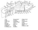
- FIG. 1depicts a longitudinal cross-section of a tactile sensor in the form of a finger pad, in accordance with exemplary embodiments of the present disclosure
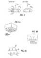
- FIG. 2depicts several views including a detail of a fill-port disassembled (A) and assembled (B), and detail of resealing forces present on the fill-port (C), in accordance with exemplary embodiments of the present disclosure;
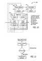
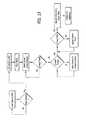
- FIG. 3depicts a schematic of the electronic system for signal detection and processing, in accordance with exemplary embodiments of the present disclosure
- FIG. 4depicts forces diagrams of a tactile sensor, showing measurement of both normal and shear forces, at a cross section of the tactile sensor subjected to low shear force (A), and a cross section of the tactile sensor subjected to high shear force (B), in accordance with exemplary embodiments of the present disclosure;
- FIG. 5depicts an internally textured skin with asperities; a perspective view is shown (A), a side view depicts an uncompressed state, (B) and a side view is shown depicting an applied force that compresses the textured rubber and narrows the flow path of the fluid to the electrode surface (C), in accordance with exemplary embodiments of the present disclosure;
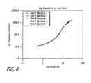
- FIG. 6illustrates a five-times-repeatability log-log plot of force versus impedance for a skin incorporating inner-surface asperities with dimensions 0.25 tall ⁇ 0.25 mm diameter, in accordance with exemplary embodiments of the present disclosure
- FIG. 7demonstrates pressure signals associated with contact and sliding for a variety of contact events: tapping (A), pushing (B), sliding (C), and poking (D), along with an AC pressure signal (E) on the same time scale as normal and tangential forces as recorded by a force plate (F), in accordance with exemplary embodiments of the present disclosure;
- FIG. 8shows spectrograms of vibration signals used to discriminate textured surfaces, in accordance with exemplary embodiments of the present disclosure
- FIG. 9illustrates a cross section of synthetic skin with ridges performing the function of fingerprints to enhance vibrations, in accordance with exemplary embodiments of the present disclosure
- FIG. 10depicts a block diagram of a system with a manipulator, display, control features, and signal processing features, in accordance with exemplary embodiments of the present disclosure
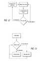
- FIG. 11depicts a flow chart for detecting friction coefficient, in accordance with exemplary embodiments of the present disclosure
- FIG. 12depicts a flow chart for controlling grip force with a known friction coefficient while also checking for slip, in accordance with exemplary embodiments of the present disclosure
- FIG. 13depicts a flow chart for controlling grip force using only slip detection, in accordance with exemplary embodiments of the present disclosure
- FIG. 14depicts a flow chart for controlling exploratory movements for discriminating textures using vibration sensing, in accordance with exemplary embodiments of the present disclosure.
- FIG. 15depicts a flow chart for controlling exploratory movements and signal processing related to characterizing thermal properties of contacted objects, in accordance with exemplary embodiments of the present disclosure.
- a prosthetic hand or anthropomorphic robotic manipulator in accordance with the present disclosurecan combine several sensor assemblies at the ends of appendages controlled by actuators, similar to the individual finger tips of a biological hand or foot.
- Pad-like structures with sensorscan be deployed on grip contact surfaces akin to the palmar eminences over the heads of the metacarpal bones etc.
- One or more such sensor assembliescould be built with various sizes and shapes and mounted in varying numbers and positions on a variety of hand-like or foot-like locomotor supports to interact with external objects while utilizing information derived from a plurality of contact sensors having one or more types of sensing modalities.
- the plurality of sensors and their associated mechanical structurescan have similarities to the biological relationships among the cutaneous neural receptors, the distal phalanx, overlying finger pulp and covering skin and nail.
- Informationmay be extracted from such a plurality of sensors whereby such information can be related to canonical physical representations used to describe stimuli to be sensed, and/or used to control automatic adjustments of grip forces similar to the neural reflexes whereby humans maintain stable grip on complex objects.
- a sensor assembly 100can consist of mechanical elements corresponding to a biological fingertip, namely a molded, rigid core 1 corresponding to the bone, a molded, elastomeric skin 16 corresponding to the biological skin, a fluid-filled space 2 corresponding to the deformable pulp of a biological finger, and a plate 22 affixing the skin 16 to the top surface of the fingertip corresponding to a fingernail.
- One embodiment of the present devicemay consist of a set of sensors that work by measuring electrical impedances through a weakly conductive fluid in contact with a plurality of electrodes.
- the electrodesmay be deployed on a substantially rigid core that is protected from direct contact with external objects by overlying deformable structures.
- a feature of this designmay be the location of mechanically vulnerable connections between the electrodes and the signal processing circuitry, which are wholly contained within the substantially rigid core.
- a related featuremay be that this design enables methods of manufacture and repair that are simple and efficient.
- sensorsmay be incorporated alone or in various combinations:
- Impedance Sensingelectrodes 6 on the surface of the core 1 that are used to detect changes in the impedance through the weakly conductive fluid that arise as a result of deformation of the overlying skin 16 ;
- Pressure Sensingone or more pressure sensors 10 that detect pressure changes and vibrations conveyed through a fluidic path 4 from the skin 16 to the pressure sensors 10 ;
- Temperature Sensinga temperature sensor (e.g., thermistor 15 ) capable of detecting temperature and temperature fluctuations.
- one or more sensor assemblies 100 and their associated signal conditioning circuitry 9can be incorporated into actuated manipulators 500 that perform exploratory movements that both rely on the signals from the sensors 100 to control their movements and interactions with external objects and surfaces and utilize signals from the sensors 100 to identify various properties of external objects and surfaces.
- a sensor assembly 100consists of a substantially rigid central core 1 covered by an elastomeric skin 16 .
- the surface of core 1contains a multiplicity of electrodes 6 .
- a weakly conductive fluidis introduced into space 2 thereby separating skin 16 from that region of the core 1 where electrodes 6 are located.
- the edge of skin 16is shaped and dimensioned into collar 20 which provides a seal to core 1 to prevent leakage of the fluid; the force affecting this seal may be augmented by shrinking band 21 .
- the portion of skin 16 that lies on the top portion of sensor assembly 100is compressed against core 1 by plate 22 , which is held in place by screws 23 tightened into threaded inserts 24 in core 1 .
- the overall structureis similar to a human fingertip with a fingernail.
- the weakly conductive fluidcan be introduced into space 2 via hypodermic needle 26 during manufacture or servicing. Plates 19 molded into skin 16 create pressure seals around screws 23 and hole 25 where the pressurized region of skin 16 forms a resealable injection port when punctured by hypodermic needle 26 . This process can be aided by monitoring the fluidic pressure as sensed by a pressure sensor 10 to inflate to a prescribed hydraulic pressure level.
- the choice of the weakly conductive fluidis a solution of 0.4M Nal in propylene glycol.
- One choice of the inert fluid in contact with the pressure sensoris mineral oil. It is desirable to protect the transductive electronic elements of pressure sensor 10 from contact with the salt ions that provide the electrical conductivity of the weakly conductive fluid, hence the requirement that these two fluids be immiscible in each other. It is also desirable the weakly conductive fluid not lose substantial volume by outward diffusion through skin 16 or gain substantial volume by inward diffusion of water if the sensor is used in a humid or wet environment. This can be achieved by the selection of propylene glycol as the solvent base of the weakly conductive fluid and silicone elastomer for the skin 16 . These examples are illustrative only; other combinations of fluids and elastomers meeting these general requirements can be practiced within the scope of the present disclosure.
- core 1The components that are contained within core 1 can be preassembled mechanically and electrically via flex circuit 5 and loaded into the injection mold used to form core 1 . These mechanical and electrical connections can be made by conventional techniques well-known to practitioners of the art, including soldering and conductive epoxy. These components include electrodes 6 , which can be made from disks of conductive, inert metals such as gold or platinum, thermistor 15 , pressure sensor 10 in housing 11 , and electronic components 9 as required for signal conditioning and processing as described later.
- electrodes 6which can be made from disks of conductive, inert metals such as gold or platinum, thermistor 15 , pressure sensor 10 in housing 11 , and electronic components 9 as required for signal conditioning and processing as described later.
- the sensor assembly 100has been designed with many features such that the sensing mechanisms are robust and protected by the rigid core 1 . This permits for the sensor assembly 100 to have a prolonged useful life before needing replacement.
- the elastic skin 16however through normal operation will wear down at a much faster rate and will need to be replaced in more frequent service intervals.
- the design of this tactile sensorconsisting of a homogeneous elastic skin which contains no electronics provides a unique advantage of low repair costs as the materials for casting skins are comparatively cheap than skins used in competing technologies.
- injecting fluid into the devicemay be made possible by inserting a hypodermic needle 26 through hole 25 in plate 22 which was designed to reseal after the hypodermic needle 26 is removed.
- Novel aspects of this designinclude forming the elastic skin 16 , rigid plate 22 and rigid core in such a way that once compressed and held together with screws 23 the resulting pressure produces adequate sealing properties, this is illustrated in FIGS. 2 (A) and (B).
- the skin 16is thickened to permit for the development of compression forces from the rigid surfaces it contacts once assembled.
- the core 1 and plate 22are made of a material of higher stiffness than the skin to ensure that the skin absorbs the deformation. As shown in FIG.
- the rigid surfaces on the core 1 and the place 22 that come into contact with the deformable skin 16are angled such that the resultant forces produce compression perpendicular to the axis in which the hypodermic needle 26 will be inserted. Once the syringe is removed these forces act to reseal the tiny hole that was created when the hypodermic needle 26 was inserted. This allows for the skin 16 to have a longer lifetime over more inflation cycles before needing to be replaced.
- Impedance Sensingmay be accomplished by measuring changes in the electrical impedance among electrodes 6 whose distribution and location on the contoured surface of the core 1 may be a key factor in the sensing properties of the sensor assembly 100 .
- detection circuitry 9is illustrated schematically in FIG. 3 and described in more detail below.
- the electrical impedances Z 0-15 so measuredcan be dominated by the dimensions and electrical properties of the weakly conductive fluid in space 2 . These dimensions are changed by forces applied to skin 16 , which result in deformation of the skin 16 and displacement of the weakly conductive fluid.
- Multiplexer 215selects each electrode in turn for connection to the measurement circuitry under the control of microcontroller 230 .
- the impedance Z of a selected electrode 6can be measured by applying a voltage to a circuit consisting of one or more excitation electrodes 6 located elsewhere on the surface of core 1 in series with selected electrode 6 and the intervening weakly conductive fluid path between them plus a fixed reference resistor 220 labeled R load .
- the applied voltageis an alternating or pulsatile voltage that does not result in net direct current flow through the electrodes 6 which would tend to damage them by inducing electrolysis and corrosion. In the preferred embodiment in FIG. 3 , this is achieved by using a clock signal CLK in series with a DC blocking capacitor, but other configurations would be obvious to someone normally skilled in the art.
- R loadplus the selected one of Z 0-15 constitute a voltage divider such that the voltage measured across R load varies inversely with the selected impedance from Z 0-15 .
- Pressure Sensingmay be accomplished by one or more pressure sensors 10 , whose transductive elements are represented by the variable resistors in the bridge circuits P AC and P DC in FIG. 2 .
- Pressure Sensingcan be usefully divided into the relatively large, quasistatic pressures P DC in the fluids, which are measured by pressure sensing subsystem 205 , and the much smaller, audio frequency vibrations P AC arising as the skin 16 slides over objects in contact with sensor assembly 100 , which are measured by vibration sensing subsystem 205 .
- the sensitivity and dynamic range of a pressure sensor 10depends on the nature of the material contained within its associated reference channel 13 within its housing 11 .
- pressure sensing subsystem 205includes a wide dynamic range pressure sensor 10 and its reference channel 13 is filled with an air pocket that is trapped there by cap 14 .
- the vibration sensing subsystem 205includes a narrow dynamic range pressure sensor 10 that needs only to be sensitive to alternating fluctuations in pressure. This is achieved by trapping an air pocket in its reference channel 13 but connecting the other side of the reference channel via a small gage tube (not illustrated) back to its inlet channel 12 .
- the combination of an incompressible fluid path in the inlet channel 12 and a compressible air bubble in series with the high fluidic resistance of the small gage tubeconstitutes a mechanical high pass filter, protecting pressure sensor 10 from large hydrostatic pressures that may arise in the fluid during the initial inflation of space 2 or firm contact with external objects. This allows for use of a more sensitive transducer with smaller dynamic range but larger signal-to-noise ratio. Alternatively, if a single pressure sensor 10 is available with sufficient dynamic range and signal-to-noise values, both pressure and vibration information may be extracted from it using analog or digital signal conditioning means as would be obvious to one normally skilled in the art.
- the signals from the one or more pressure sensors 10are suitably amplified by ⁇ 100 and digitized by ADC channels in microcontroller 230 .
- Temperature Sensingmay be accomplished via thermistor 15 and associated circuitry described in FIG. 3 . Temperature Sensing may be usefully divided into i) quasistatic sensing of ambient temperature T DC by thermistor 15 in DC temperature subsystem 240 ; and ii) dynamic sensing of local fluctuations in temperature T AC by AC temperature subsystem 235 . Such fluctuations in temperature that may be induced by contact between the region of the skin 16 overlying thermistor 15 (as illustrated mechanically in FIG. 1 ) and an external object at a temperature different from the ambient temperature. The ambient temperature in sensor assembly 100 depends on the equilibrium between heat energy generated through the operation of all of its electronic components 9 and the heat energy conducted away by various conductive, convective, and radiative losses.
- the heat energy generatedwill tend to be dominated by the contribution from microcontroller 230 , whose power dissipation can be controlled dynamically by its software, for example by changing its clock rate or sleep intervals.
- the ambient temperature in the environment around sensor assembly 100can thus be inferred by the amount of heat energy that can be generated to keep thermistor 15 at a desired temperature, such as the 37 C core temperature of the human body.
- T DCis sensed by a voltage divider and amplifier, one of many measurement circuits that would be well-known to practitioners of the art.
- the fluctuations T ACwill depend on the difference between the temperature of the core 1 and the temperature of a contacting object, the thermal conductivity of that contacting object, and the location, extent and force of contact between sensor assembly 100 and the contacting object. These fluctuations can be high-pass filtered and amplified to generate T AC .
- the signals from DC temperature subsystem 240 and AC temperature subsystem 235are digitized by ADC channels in microcontroller 230 .
- a manipulator 500(described in more detail below in FIG. 10 ) to the one or more sensor assemblies 100 incorporated into a manipulator 500 .
- Thiscan be done by multiplexing the data derived from all of the sensing functions in each sensor assembly 100 into a serial stream of digital bits.
- the circuitry required for energizing the sensors, analog signal conditioning, digitization and serialization into a standard protocol (e.g., SPI or I2C)may be located physically in the fingertip, along with the various electrodes 6 , other transducers and their electrical connections.
- a simple circuitcan be built from off-the-shelf components, including integrated circuits that could be procured as surface-mount packages or bare dies and incorporated onto flex circuit 5 .
- FIG. 4illustrates a cross-sectional view of sensor assembly 100 that is orthogonal to the view in FIG. 1 .
- the positioning of the electrodes 6 with respect to the contours of the core 1 and overlying fluid-filled space 2 and skin 16may cause distinct patterns of change in the various impedances Z 0-15 measured by electronic components 9 as the sensor assembly 100 contacts various objects and surfaces with various force vectors. It may be useful to identify how different aspects of any particular stimulus parameter to be sensed will influence the array of electrodes comprising the sensor assembly 100 .
- a single point of contactmay experience various combinations of normal and tangential force components (labeled Fnorm and Ftang, respectively), which result in distributed changes in the impedances measured at each of the electrodes 6 as a result of sliding and deformation of skin 16 with respect to core 1 and plate 22 .
- Fnorm and Ftangnormal and tangential force components
- Sensor assembly 100can have properties similar to the biological fingertip, however, so it may likely require non-analytical signal processing methods similar to those employed by the biological nervous system.
- the temporospatial distribution of activity in the biological touch sensorsdepends complexly on the inherent sensitivity of the sensors, their distributions throughout the tissues of the fingertip and the forces that the fingers apply to external object, as well as on the nature of the external object itself.
- force magnitude and locationinteract with each other. For example, the same force vector applied close to the nail bed may create a different amount of net impedance change than if applied to the fingertip; the total change in impedance may not be used as a measure of the applied force unless corrected for the position.
- the information about positionmay be blurred because of nonlinear changes in electrode impedance as the inside surface of the skin makes contact with the electrodes. This is similar to the saturation of light touch receptors and the need to incorporate information from deep touch and nociceptors in biological skin.
- the characterization experiments described abovemay produce a rich data set consisting of pairs of input vectors (describing location and components of applied force) and output vectors (voltages related to impedances of the electrode array). These may be used to train neural networks for various tasks. This approach can be used to determine the discriminability of various input conditions or, conversely, to determine the ability to generalize a single parameter such as magnitude of forces applied to different portions of the finger tip.
- a multi-layer perceptron (MLP) and radial-basis neural networkmay be used initially because both have proven to be able to approximate any given non-linear relation when a sufficient number of neurons are provided in the hidden layer.
- Two-point discriminationmay likely be possible but may depend critically on the thickness and viscoelastic properties of the skin. It may be feasible to employ algorithms known as neural networks that may function similar to those embodied in the nervous system in order to identify the nature of the contact state in terms of feature of contacted objects and spatiotemporal distribution of contact forces. That is, neural networks can be trained by learning to respond in a useful manner to those features of any stimulus that can be discriminated, as would be obvious to one normally skilled in the art. Active feature extraction is described in more detail in FIGS. 10-15 and related text.
- the dynamic range of forces that can be measured usefully by Impedance Sensingdepends on the rate at which space 2 over a given electrode 6 tends to be occluded by increasing force applied to the overlying skin 16 .
- the measured electrical impedance of the sensing electrodemay rise abruptly and to saturate when the skin is pressed against it, forming a tight seal.
- the inner surface of skin 16can include asperities 18 molded into the contour of the skin, for example, by forming skin 16 in an injection mold whose corresponding surface is a negative of the desired pattern of asperities 18 .
- Other methods of fabrication of textureswould be obvious to one normally skilled in the art, including photolithography, incorporation of soluble particles, plasma etching, etc.
- Related U.S. patent application Ser. No. 11/692,718teaches that it may be desirable to have the inside surface of the skin patterned with “bumps and/or ridges”.
- FIG. 5Aillustrates one advantageous embodiment of a useful surface textural feature consisting of a repeated pattern of closely spaced asperities 18 , each of which is a pyramidal or columnar protrusions from the inner surface of skin 16 .
- Such a patterntends to leave channels of conductive fluid on the surface of core 1 and electrodes 6 , which channels may be gradually compressed and narrowed with increasing compressive force applied to the skin, as illustrated in cross-sectional views in FIGS. 5B and 5C .
- FIG. 6illustrates a wide dynamic range of input normal forces (log scale on abscissa) that result in a wide dynamic range of output electrode impedance (log scale on ordinate) for a pattern of cylindrical asperities 0.25 mm tall, 0.25 mm in diameter and 0.5 mm apart in a regular, square grid.
- the dynamic rangecan be extended by texturing the inner surface of the elastomeric skin.
- a suitable sensor corecan be fabricated by creating a negative mold of the desired core shape, advantageously using a relatively soft material such as machinist's wax.
- Components that need to be present on the surface of the moldcan be affixed in the desired locations by pressing them onto the surface of the mold. Any desired mechanical or electrical connections from those components can be made to electronic circuits or connector pins in the open mold. All of the components and their interconnections are then embedded in the core material that is poured into the mold around the components and cured in place.
- High density polyurethanecan be used to form the core. This method lends itself well to rescaling the tactile array for different applications, changing the curvature of its surface, and/or changing the number and distribution of electrode contacts.
- the above-described method of forming the core by pouring and polymerizing the core materialmay be particularly well-suited for creating a rugged protective enclosure around such signal conditioning circuitry, which may obviate the need for bulky and expensive hermetic packaging and feedthroughs for the electronic circuitry.
- the material chosen for the coreshould be relatively impermeable to the fluid chosen to inflate the fingertip.
- FIG. 7illustrates the signals produced by a pressure sensor 10 connected to the incompressible fluid occupying space 2 of a sensor assembly 31 as it contacts a flat, hard surface with different patterns of force and motion.
- the output of pressure sensing subsystem 210 reflecting P DCis provided as a function of time during various contact events.
- the output of vibration sensing subsystem 205 reflecting P ACis provided as a function of time, along with the normal and tangential reaction forces ( FIG. 7F ) recorded by a commercial force-plate under the surface being contacted. Friction-induced vibrations in skin 16 are sensed as fluctuations in fluid-pressure by pressure sensor 10 having a bandwidth of approximately 0-1000 Hz.
- An exemplary embodimentincluded a commercially available pressure transducer (Honeywell Model #40PC015G1A) and based on the vibration sensitivity of the human finger an analog first-order low-pass filter with center frequency at 1000 Hz and a digital sampling rate of 2500 samples/sec were used.
- Fidelity of transmission of acoustic signalsis a concern when measuring dynamic fluctuations in pressure from a signal source at a remote location.
- Important parameters to considerare the geometries of pathways involved between the signal source and recording site as well as the wavelengths of signals being recorded.
- the wavelength of a signal ( ⁇ )can be calculated from the speed of sound in a media (c) and the frequency of the signal (f) from the following formula
- pressure sensor 10provides easily detected audio frequency signals when skin 16 starts to slip over a contact object.
- Dynamic information correlated with sliphas been shown to lie in frequencies between 50-700 Hz using this approach. This correlates well with what is known of biological slip detection mechanisms. Presence of frequency content within this band is not unique to slip and is also common to other dynamic events such as shock or contact. However, slip events are unique in that they have significantly less spectral information in low frequency bands (0-50 Hz) with respect to these other dynamic events, as shown in FIGS. 7 (A), (B) and (D). In experiments conducted by the inventors, the absence of low-frequency vibrations combined with the presence of high-frequency vibrations tended to occur only during slip when contacting passive objects.
- the sensordetects different spectral patterns as it is slid across surfaces of different texture.
- the sensoris capable of performing texture discrimination tasks when used in conjunction with mechanical means to slide the sensor over textures to be discriminated.
- Textureshave been shown to provide characteristic, repeatable, and identifiable frequency patterns when observed visually on short-time Fourier transform spectrograms or when listened to acoustically.
- One such signal processing method for extracting this in an automated fashionis to use a short-time Fourier transform with a wide time window. This wide time window is desired to improve the frequency resolution of this transform and improve the ability to discriminate between different textures.
- a regular pattern of ridges 17 similar to those found on human fingers or bumps similar to those found on the fingerpads of raccoonscan be incorporated onto the exterior of the elastic skin as depicted in FIG. 9 .
- the cantilever structure of the elastic ridges 17allows for energy to be stored in the bending of these structures as tangential movements are applied. This stored elastic potential produces a force at the contact surface which is maintained by the friction between the ridges 17 and the object being contacted.
- these vibrations in the skin 16are conveyed through the incompressible fluid occupying space 2 and detected by the pressure sensor 10 .
- these ridges 17are incorporated into the surface of skin 16 during its manufacture by injection molding into a cavity whose surface includes a negative of the desired ridge pattern. Other methods of forming or attaching ridges 17 or other textural patterns performing a similar function would be obvious to one normally skilled in the art.
- Impedance Sensingdepends on the conductivity of the weakly conductive fluid, which tends to vary directly with the temperature of the fluid.
- the ambient core temperature detected as T DCcan be measured and stabilized via a feedback control algorithm that adjusts the power dissipation of electronic components 9 .
- Pressure Sensing of vibrations produced by slippage between sensor assembly 100 and the contacting objectdepend on the location, extent and force of contact between them. These mechanical factors can all be extracted from the Impedance Sensing and used in a feedback control scheme to adjust the nature of the contact to standardized values, much as humans tend to standardize their exploratory movements when trying to identify the texture of an unknown surface.
- Temperature Sensing of fluctuations produced by contact with an external objectdepend on the location, extent and force of contact between sensor assembly 100 and the contacting object. These mechanical factors can all be extracted from the Impedance Sensing and used in a feedback control scheme to adjust the nature of the contact to standardize values, much as humans tend to standardize their exploratory movements when trying to identify an unknown object.
- FIG. 10provides a block diagram of a complete system 1000 for control and sensing in a multi-articulated manipulator, in accordance with an exemplary embodiment of the present disclosure.
- a manipulatorcan include one or more sensor assemblies 100 and one or more powered actuators 600 responsive to a controller 400 .
- Sensor signals from conditioning circuitry 9 in each sensor assembly 100is transmitted to feature extraction means 300 and may be used to provide sensory feedback to controller 400 according to the requirements of various applications described below.
- the functions performed by controller 400are partially or wholly under the command of an external operator 900 which may be a human operator or other source of commands such as would be generated in an autonomous robot.
- sensory information from feature extractor 300may be advantageously provided to operator 900 by one or more of the many haptic display interfaces now available or under development, including tactors for generating force, vibration and temperature stimuli on an innervated skin surface of the operator 900 .
- sensor assembly 100produces broadband responses to slip and texture that are similar to the signals available to the nervous system from biological tactile receptors, it enables a particularly realistic haptic display as follows.
- the signals produced by vibration sensing subsystem 205 and pressure sensing subsystem 210can be combined and applied more or less directly onto the skin of a human operator 800 with a haptic display 700 in order to produce realistic illusions of contact, slip and texture. This would be an advance over vibrotactile information currently delivered from tactors in other applications which typically stimulate at a single frequency with modulated amplitude.
- FIGS. 7 and 8illustrated that slip and texture vibrations are a combination of multiple frequency components and amplitudes. Presenting some or all of the complete set of force, vibration and temperature information sensed by biomimetic sensor assembly 100 to the skin of an operator 900 via a multimodal haptic display 700 would produce more realistic illusions of contact, slip and texture. For human user interaction such as telerobotics and prosthetics, this would be expected to improve haptic perception and dexterous manipulation of objects.
- Stabilizing a gripmay be a function whose requirements and natural strategies are starting to be well understood.
- the grip stabilitymay be affected by an object's size and shape, its mass and weight distribution, and by the coefficient of friction between the fingertips and surface of the object.
- the central nervous systemusually may adjust the grip force so that the friction force developed between the fingertips and the object surface may have a small margin over the external forces that would otherwise cause the object to slip.
- This strategymay energetically be efficient and suitable for manipulating delicate objects that might be crushed, but it demands continuous tactile sensing and adjustment of grip forces according to the perceived properties of the gripped object.
- Each finger's grip forcemay be adjusted independently based on the sensory information from that finger only and on the local conditions in terms of weight distribution and friction. At least some of this adjustment may occur so rapidly that it appears to be mediated reflexively in the spinal cord rather than via the brain. This is important for prosthetic limbs because it suggests that tactile information can serve a useful function even if communication channels to provide conscious perception of touch to the operator remain nonexistent or primitive, as they are now. Algorithms for the automatic adjustment of grip using biomimetic strategies are likely to be valuable also in telerobotic and purely robotic manipulators.
- the proposed feature extraction 300determines the static friction coefficient as outlined in the flowchart in FIG. 11 .
- Thiscan be accomplished by using an actuator 600 to deliver a fixed amount of normal contact force and a second actuator 600 to gradually increase tangential forces.
- the tangential forceis increased eventually the sensor will begin to slip along the contact surface. This moment of slip can be determined from the slip-detection feature extraction 300 .
- the ratio of normal to tangential contact forcescan be used to calculate the static friction coefficient ( ⁇ ) from the formula
- a secondary method for controlling gripcan be implemented by using the slip-detection derived from feature extraction 300 circuitry to constantly check for slip and adjust this static coefficient when slip is detected as depicted in the flow-chart in FIG. 12 .
- This active method of reevaluating the static coefficientcan reduce errors that may have occurred due to noise in sensing components and errors in evaluating the static friction coefficient. Because this strategy is more effective at maintaining grip the safety factor used in grip force from the equation above can be reduced which is advantageous for reducing the power required in the gripping actuator.
- An additional method of controlling gripwould be to slowly reduce contact force while holding an object and make small increases in force when a slip is detected as depicted in the flow-chart in FIG. 13 .
- the grip controlleris able to continuously survey if it is possible to maintain grasp of an object with a lower grip force yet maintain grasp when grip force becomes critical, thus reducing power required in the gripping actuator.
- Thisalso offers the additional advantage of not needing to determine the static friction coefficient as well as not requiring any sensors to detect normal and shear forces as described in the methods presented above.
- One proposed method for signal processing to determine slip from feature extraction 300 utilizing the acoustic fluid-pressure data as recorded by pressure sensor 10is to use a set of band-pass filters and logic that check for the characteristic signatures of slip, which are the existence of high frequency fluid-pressure fluctuations and the relative absence of low-frequency fluid-pressure fluctuations. In order to reduce false positives when using this approach it is desirable to ensure that these criteria are met and maintained for a short period of time, but not excessively long as the object may slip from grasp.
- this 60-80 ms delay as found in the biological systemcan be used to determine the confidence in slip as detected using the aforementioned methods with no loss in performance when compared to the gold standard of biological reaction times for grip adjustments. Additional methods to accomplish this digitally would to be to use short-time Fourier transforms to analyze the frequency content. When converting to the frequency domain with a time window of this size the frequency resolution is also sufficient to distinguish between low-frequency content and high-frequency content as describe above and required for accurate determination of slip. The ability to automate the detection of slip would allow for advanced biomimetic grip control mechanisms.
- an objectcan be located using robotic vision, proximity sensing, or through other means and a mechanical actuator 500 with the sensor assembly 100 attached can be moved towards the object until a contact is detected.
- Utilizing force and contact information extracted from impedance data using feature extraction 300 commandscan be delivered to the controller 400 such that the desired contact force and location are optimized in the sensor assembly 100 .
- the manipulator 500 and sensor assembly 100can be stroked along the surface while maintaining desired contacting forces and locations while recording spectral content from the pressure sensor 10 .
- At the end of the movement spectral analysiscan be performed on the recorded content and it can be compared to a library of materials for texture identification.
- thermistor 15As ionic fluids decrease in temperature, their conductivity tends to decrease. Without temperature compensation, this decrease in conductivity would result in an increase in sensed impedance, which would be interpreted as an increase in force applied between an electrode 6 and the overlying skin 16 . Referring to FIG. 1 , this problem is overcome by including in core 1 a thermistor 15 with a sufficiently short time constant relative to temperature changes to be measured.
- the sensor assembly 100If the sensor assembly 100 is heated, and contacted with an external object, its temperature will change appropriately with the mass, temperature, contact surface area, thermal conductivity and heat capacity of the object.
- One method of heating the fingerwould be through the use of a heater. These tend to be bulky and would require a controller for proper operation. Instead of using a heater, the power dissipation energy from the electronics of the control board, 9 , could be used to heat the finger.
- the heat dissipated by the microcontroller 230depends on its clock frequency and duty cycle of active use as opposed to “sleep states”. By utilizing a feedback signal from the thermistor 15 , controller 400 can adjust the clock frequency or operation duty cycle of microcontroller 230 to heat the finger to the desired temperature. By keeping track of the amount of energy so applied, it is possible to estimate the ambient temperature around sensor assembly 100 according to principles of thermodynamics that would be obvious to one ordinarily skilled in the art.
- one useful piece of informationconcerns its thermal properties.
- objects made of plastics, ceramics and metalstend to have differences in their thermal conductivity and heat capacity. Humans detect such differences as they are reflected in the time-varying rate of temperature change of the skin when it comes into contact with an object at a different temperature than that of the skin.
- the rate of heat flow between the skin and objectwill depend on many factors including the amount of pressure the object exerts on the sensor assembly 100 . As the pressure increases, the amount of surface area increases, causing an increase in the rate of heat transfer.
- humanscarefully control the location and amount of force of contact with an object when attempting to extract information about its thermal properties.
- FIG. 15illustrates an algorithm for determining thermal properties of objects based on the combination of temperature and force sensing capabilities of exemplary embodiments of the present disclosure.
- a sensor assemblye.g., sensor assembly 100 of FIG. 1
- controller 400adjusts the amount of power dissipated as heat by microcontroller 230 by changing its clock frequency or duty cycle. In the event that the measured temperature deviates from the desired value, a negative feedback loop within the heat control software will compensate for this to adjust the temperature back to the desired value.
- controller 400initiates an exploratory movement by sending commands to actuators 600 .
- Information about the timing and nature of the contact with the objectis obtained from impedance sensing electrodes 6 in order to adjust actuators 600 so that the contact conforms to a standardized exploratory behavior for determining thermal properties of objects. This behavior will generally require that the contact be centered over thermistor 15 and that normal force of contact be sufficient to displace fluid in space 2 allowing skin 16 to make firm contact directly with thermistor 15 .
- Thermal properties of materialsprovide useful information about the identity of the materials and the identity of the object, particularly when combined with visual and other information commonly available from other sensing modalities.
- embodiments and/or portions of embodiments of the present disclosurecan be implemented in/with computer-readable storage media (e.g., hardware, software, firmware, or any combinations of such), and can be distributed and/or practiced over one or more networks. Steps or operations (or portions of such) as described herein, including processing functions to derive, learn, or calculate formula and/or mathematical models utilized and/or produced by the embodiments of the present disclosure, can be processed by one or more suitable processors, e.g., central processing units (“CPUs) implementing suitable code/instructions in any suitable language (machine dependent on machine independent).
- CPUscentral processing units
Landscapes
- Chemical & Material Sciences (AREA)
- Analytical Chemistry (AREA)
- Physics & Mathematics (AREA)
- General Physics & Mathematics (AREA)
- Manipulator (AREA)
Abstract
Description
- 1.
Core 1 is designed to be injection molded around all of the internal components illustrated inFIG. 1 . - 2. At the time of molding,
tube 4 andinlet channel 12 will have already been filled with inert fluid and plugged withsoluble keeper 3 made from a material that dissolved readily upon contact with the weakly conductive fluid but not the inert fluid.Soluble keeper 3 contacts the walls of the mold so that it forms a continuous path from the location of the resealable injection port to thespace 2 to be inflated with weakly conductive fluid. - 3.
Core 1 can be inserted intoskin 16 without introducing air pockets by performing this step while submerged in a fluid. - 4.
Soluble keeper 3 can be made from a material such as polyvinyl alcohol that can be softened by heating and then displaced and dissolved by the weakly conductive fluid when it is introduced viahypodermic needle 26.
Given the inherently long wavelengths of these frequencies in candidate fluids, even the shortest wavelength of interest is on the order of 1 meter. This makes it possible to displace the
This friction coefficient is unique to the coupling of the skin and the object it is touching.
However, without a suitable method of determining the static friction coefficient between a the gripping surface and an unknown object the assumed friction coefficient can be combined with an unnecessarily high safety factor to maintain grasp on objects with a wide range of friction properties, which is undesirable for the handling of fragile objects.
Claims (30)
Priority Applications (1)
| Application Number | Priority Date | Filing Date | Title |
|---|---|---|---|
| US12/417,532US8181540B2 (en) | 2006-03-28 | 2009-04-02 | Measurement of sliding friction-induced vibrations for biomimetic tactile sensing |
Applications Claiming Priority (10)
| Application Number | Priority Date | Filing Date | Title |
|---|---|---|---|
| US78660706P | 2006-03-28 | 2006-03-28 | |
| US11/692,718US7658119B2 (en) | 2006-03-28 | 2007-03-28 | Biomimetic tactile sensor |
| US93900907P | 2007-05-18 | 2007-05-18 | |
| US4186108P | 2008-04-02 | 2008-04-02 | |
| US4186708P | 2008-04-02 | 2008-04-02 | |
| US4186508P | 2008-04-02 | 2008-04-02 | |
| US4186808P | 2008-04-02 | 2008-04-02 | |
| US4218208P | 2008-04-03 | 2008-04-03 | |
| US12/122,569US7878075B2 (en) | 2007-05-18 | 2008-05-16 | Biomimetic tactile sensor for control of grip |
| US12/417,532US8181540B2 (en) | 2006-03-28 | 2009-04-02 | Measurement of sliding friction-induced vibrations for biomimetic tactile sensing |
Related Parent Applications (1)
| Application Number | Title | Priority Date | Filing Date |
|---|---|---|---|
| US11/692,718Continuation-In-PartUS7658119B2 (en) | 2006-03-28 | 2007-03-28 | Biomimetic tactile sensor |
Publications (2)
| Publication Number | Publication Date |
|---|---|
| US20100139418A1 US20100139418A1 (en) | 2010-06-10 |
| US8181540B2true US8181540B2 (en) | 2012-05-22 |
Family
ID=42229578
Family Applications (1)
| Application Number | Title | Priority Date | Filing Date |
|---|---|---|---|
| US12/417,532Active2028-10-29US8181540B2 (en) | 2006-03-28 | 2009-04-02 | Measurement of sliding friction-induced vibrations for biomimetic tactile sensing |
Country Status (1)
| Country | Link |
|---|---|
| US (1) | US8181540B2 (en) |
Cited By (16)
| Publication number | Priority date | Publication date | Assignee | Title |
|---|---|---|---|---|
| US20130238129A1 (en)* | 2012-03-08 | 2013-09-12 | Quality Manufacturing Inc. | Touch sensitive robotic gripper |
| US20140026682A1 (en)* | 2012-07-27 | 2014-01-30 | Seda Chemical Products Co., Ltd. | Imperceptible motion sensing device having conductive elastomer |
| WO2014043037A1 (en) | 2012-09-11 | 2014-03-20 | SynTouch, LLC | Compliant tactile sensor with fluid-filled, sponge-like material |
| US20150019013A1 (en)* | 2012-03-08 | 2015-01-15 | Quality Manufacturing Inc. | Touch sensitive robotic gripper |
| US9218565B2 (en) | 2013-12-18 | 2015-12-22 | International Business Machines Corporation | Haptic-based artificial neural network training |
| US9477909B2 (en) | 2013-01-09 | 2016-10-25 | SynTouch, LLC | Object investigation and classification |
| US10559377B2 (en) | 2013-01-09 | 2020-02-11 | Biomed Concepts Inc. | Graphical user interface for identifying diagnostic and therapeutic options for medical conditions using electronic health records |
| US10687753B2 (en)* | 2015-09-30 | 2020-06-23 | 3M Innovative Properties Company | System and method for optimizing body and object interactions |
| US10718359B2 (en) | 2015-08-21 | 2020-07-21 | Quality Manufacturing Inc. | Devices and systems for producing rotational actuation |
| US20210129347A1 (en)* | 2018-06-22 | 2021-05-06 | Sony Corporation | Controller, control method, and program |
| US20230126506A1 (en)* | 2021-10-21 | 2023-04-27 | Auris Health, Inc. | Drift detection of a haptic input device in a robotic surgical system |
| US11737896B2 (en) | 2012-07-31 | 2023-08-29 | Purdue Research Foundation | Wirelessly-powered implantable EMG recording system |
| US11860048B2 (en) | 2017-07-10 | 2024-01-02 | The Board Of Trustees Of The Leland Stanford Junior University | Capacitive and tactile sensors and related sensing methods |
| US11867574B1 (en) | 2023-05-23 | 2024-01-09 | Sanctuary Cognitive Systems Corporation | Fluidic tactile sensor |
| US12103182B1 (en) | 2023-10-20 | 2024-10-01 | Tacta Systems Inc. | Tactile robotic training platform |
| US12410053B1 (en) | 2024-07-29 | 2025-09-09 | Tacta Systems Inc. | Embedded digital sensor structure |
Families Citing this family (21)
| Publication number | Priority date | Publication date | Assignee | Title |
|---|---|---|---|---|
| US8033189B2 (en)* | 2005-12-28 | 2011-10-11 | Honda Motor Co., Ltd. | Robot skin |
| US8272278B2 (en)* | 2007-03-28 | 2012-09-25 | University Of Southern California | Enhancements to improve the function of a biomimetic tactile sensor |
| JP4678550B2 (en)* | 2008-11-19 | 2011-04-27 | ソニー株式会社 | Control apparatus and method, and program |
| JP5445065B2 (en) | 2009-11-25 | 2014-03-19 | セイコーエプソン株式会社 | Shear force detection element, tactile sensor, and gripping device |
| JP5821322B2 (en) | 2010-07-26 | 2015-11-24 | セイコーエプソン株式会社 | Detection device, electronic device and robot |
| US20120092286A1 (en)* | 2010-10-19 | 2012-04-19 | Microsoft Corporation | Synthetic Gesture Trace Generator |
| US9613180B1 (en)* | 2011-06-02 | 2017-04-04 | Hrl Laboratories, Llc | Robotic control device and method for manipulating a hand-held tool |
| US10222279B1 (en)* | 2014-06-19 | 2019-03-05 | Amazon Technologies, Inc. | Force measurement device |
| USD783820S1 (en)* | 2015-03-18 | 2017-04-11 | University Of Houston System | Finger tip shaped enclosure |
| US9744677B2 (en) | 2015-11-05 | 2017-08-29 | Irobot Corporation | Robotic fingers and end effectors including same |
| DE102016226136A1 (en)* | 2016-12-23 | 2018-06-28 | Robert Bosch Gmbh | Method for operating a sensor device, sensor device |
| US11199460B2 (en) | 2017-03-21 | 2021-12-14 | University Of Washington | Soft shear force resistive sensor embedded in artificial skin |
| CN108932084B (en)* | 2017-05-24 | 2022-05-27 | 苹果公司 | Systems and methods for acoustic touch and force sensing |
| CN107255535B (en)* | 2017-05-31 | 2019-05-21 | 广西医科大学 | A kind of vibrating wire sensor frequency measuring method, device and equipment |
| CN108072464B (en)* | 2017-11-30 | 2019-10-29 | 东南大学 | A kind of imitation human finger end sliding touch sensor |
| US11273555B2 (en)* | 2018-09-20 | 2022-03-15 | Rios Intelligent Machines, Inc. | Multimodal sensor array for robotic systems |
| GB2577680B (en)* | 2018-09-25 | 2021-05-05 | Covvi Ltd | A mechanical hand |
| US20220357225A1 (en)* | 2019-10-24 | 2022-11-10 | The Board Of Trustees Of The Leland Stanford Junior University | Devices and methods involving sensing in response to an applied touch or other force |
| CN113029321B (en)* | 2021-02-26 | 2023-08-04 | 中国兵器工业集团第二一四研究所苏州研发中心 | Capacitive MEMS vector acoustic wave sensor capable of inhibiting vibration interference and processing method thereof |
| CN113310607B (en)* | 2021-06-24 | 2022-05-24 | 华中科技大学 | A flexible tactile sensing array, preparation method and application thereof |
| CN116749217A (en)* | 2023-05-12 | 2023-09-15 | 苏州大学 | A bionic tactile mechanism, robot dexterous hand and robot |
Citations (127)
| Publication number | Priority date | Publication date | Assignee | Title |
|---|---|---|---|---|
| US4014217A (en) | 1975-11-28 | 1977-03-29 | Agence Nationale De Valorisation De La Recherche Etablissement Public De Droit | Tactile pick-up |
| US4306148A (en) | 1980-01-21 | 1981-12-15 | General Electric Company | Tactile sensor |
| US4481815A (en) | 1982-12-23 | 1984-11-13 | Overton Kenneth J | Tactile sensor |
| US4492949A (en) | 1983-03-18 | 1985-01-08 | Barry Wright Corporation | Tactile sensors for robotic gripper and the like |
| US4521685A (en) | 1982-03-01 | 1985-06-04 | Lord Corporation | Tactile sensor for an industrial robot or the like |
| US4526043A (en) | 1983-05-23 | 1985-07-02 | At&T Bell Laboratories | Conformable tactile sensor |
| US4555953A (en) | 1984-04-16 | 1985-12-03 | Paolo Dario | Composite, multifunctional tactile sensor |
| US4555954A (en) | 1984-12-21 | 1985-12-03 | At&T Technologies, Inc. | Method and apparatus for sensing tactile forces |
| US4574438A (en) | 1982-09-29 | 1986-03-11 | Siemens Aktiengesellschaft | Method of making pressure-sensitive transducer |
| US4581491A (en)* | 1984-05-04 | 1986-04-08 | Research Corporation | Wearable tactile sensory aid providing information on voice pitch and intonation patterns |
| US4584625A (en) | 1984-09-11 | 1986-04-22 | Kellogg Nelson R | Capacitive tactile sensor |
| US4616511A (en) | 1985-02-20 | 1986-10-14 | Eaton Corporation | Tactile sensor |
| US4621533A (en) | 1984-11-19 | 1986-11-11 | Eaton Corporation | Tactile load sensing transducer |
| US4634917A (en) | 1984-12-26 | 1987-01-06 | Battelle Memorial Institute | Active multi-layer piezoelectric tactile sensor apparatus and method |
| US4640137A (en) | 1985-05-31 | 1987-02-03 | Lord Corporation | Tactile sensor |
| US4694231A (en) | 1986-04-18 | 1987-09-15 | Mecanotron Corporation | Robotic skin |
| US4709342A (en)* | 1983-08-03 | 1987-11-24 | Hitachi, Ltd. | Tactile sensing apparatus |
| US4712037A (en) | 1985-07-03 | 1987-12-08 | Nederlandse Centrale Organisatie Voor Toegepast-Natuurwetenschappelijk Onderzoek | Resonant piezoelectric sensor |
| US4715235A (en) | 1985-03-04 | 1987-12-29 | Asahi Kasei Kogyo Kabushiki Kaisha | Deformation sensitive electroconductive knitted or woven fabric and deformation sensitive electroconductive device comprising the same |
| US4745812A (en) | 1987-03-25 | 1988-05-24 | The United States Of America As Represented By The Secretary Of The Army | Triaxial tactile sensor |
| US4747313A (en) | 1986-01-13 | 1988-05-31 | Agency Of Industrial Science And Technology | Tactile sensor |
| US4813732A (en) | 1985-03-07 | 1989-03-21 | Epsilon Technology, Inc. | Apparatus and method for automated wafer handling |
| US4814562A (en) | 1987-11-13 | 1989-03-21 | University Of Arkansas | Electro-optic force and pressure transducer and sensor |
| US4817440A (en) | 1985-10-18 | 1989-04-04 | The Board Of Governors For Higher Education, State Of Rhode Island And Providence Plantations | Compliant tactile sensor |
| US4866412A (en)* | 1986-08-14 | 1989-09-12 | The Microelectronics Applications Research Institute Limited | Tactile sensor device |
| US4886361A (en) | 1987-05-12 | 1989-12-12 | Versuchsanstalt fur Luft | Flat tactile sensor |
| US4945305A (en) | 1986-10-09 | 1990-07-31 | Ascension Technology Corporation | Device for quantitatively measuring the relative position and orientation of two bodies in the presence of metals utilizing direct current magnetic fields |
| US4964302A (en) | 1984-09-25 | 1990-10-23 | Grahn Allen R | Tactile sensor |
| US4980646A (en) | 1988-03-30 | 1990-12-25 | The Trustees Of The University Of Pennsylvania | Impedance tomographic tactile sensor |
| US5010774A (en) | 1987-11-05 | 1991-04-30 | The Yokohama Rubber Co., Ltd. | Distribution type tactile sensor |
| US5014224A (en) | 1988-07-14 | 1991-05-07 | Blomberg Robotertecknik Gmbh | Tactile sensor |
| US5033291A (en) | 1989-12-11 | 1991-07-23 | Tekscan, Inc. | Flexible tactile sensor for measuring foot pressure distributions and for gaskets |
| US5060527A (en) | 1990-02-14 | 1991-10-29 | Burgess Lester E | Tactile sensing transducer |
| US5138216A (en) | 1989-01-13 | 1992-08-11 | Digital Equipment Corporation | Micro-beam tactile sensor for the measurement of vertical position displacement |
| US5193539A (en) | 1991-12-18 | 1993-03-16 | Alfred E. Mann Foundation For Scientific Research | Implantable microstimulator |
| US5193540A (en) | 1991-12-18 | 1993-03-16 | Alfred E. Mann Foundation For Scientific Research | Structure and method of manufacture of an implantable microstimulator |
| US5200679A (en) | 1990-02-22 | 1993-04-06 | Graham Douglas F | Artificial hand and digit therefor |
| US5209126A (en) | 1991-01-04 | 1993-05-11 | Bonneville Scientific | Force sensor |
| US5225959A (en) | 1991-10-15 | 1993-07-06 | Xerox Corporation | Capacitive tactile sensor array and method for sensing pressure with the array |
| US5237879A (en) | 1991-10-11 | 1993-08-24 | At&T Bell Laboratories | Apparatus for dynamically varying the resolution of a tactile sensor array |
| US5255345A (en) | 1988-02-17 | 1993-10-19 | The Rowland Institute For Science, Inc. | Genetic algorithm |
| US5261266A (en) | 1990-01-24 | 1993-11-16 | Wisconsin Alumni Research Foundation | Sensor tip for a robotic gripper and method of manufacture |
| US5311779A (en)* | 1992-01-03 | 1994-05-17 | Inabagomu Co., Ltd. | Pressure-sensitive sensor |
| US5312439A (en) | 1991-12-12 | 1994-05-17 | Loeb Gerald E | Implantable device having an electrolytic storage electrode |
| US5313840A (en) | 1992-10-30 | 1994-05-24 | At&T Bell Laboratories | Tactile shear sensor using anisotropically conductive material |
| US5373747A (en) | 1991-03-30 | 1994-12-20 | Kabushiki Kaisha Toshiba | Robot hand and robot |
| US5501498A (en) | 1988-08-31 | 1996-03-26 | The Trustees Of The University Of Pennsylvania | Methods and apparatus for mechanically intelligent grasping |
| US5510812A (en) | 1994-04-22 | 1996-04-23 | Hasbro, Inc. | Piezoresistive input device |
| US5563354A (en) | 1995-04-03 | 1996-10-08 | Force Imaging Technologies, Inc. | Large area sensing cell |
| US5604314A (en) | 1994-10-26 | 1997-02-18 | Bonneville Scientific Incorporated | Triaxial normal and shear force sensor |
| US5744953A (en) | 1996-08-29 | 1998-04-28 | Ascension Technology Corporation | Magnetic motion tracker with transmitter placed on tracked object |
| US5760530A (en) | 1992-12-22 | 1998-06-02 | The United States Of America As Represented By The Secretary Of The Air Force | Piezoelectric tactile sensor |
| US5871248A (en) | 1995-09-26 | 1999-02-16 | University Of South Florida | Robot gripper |
| US5886615A (en) | 1995-04-27 | 1999-03-23 | Burgess; Lester E. | Pressure activated switching device with piezoresistive material |
| US5905485A (en) | 1997-02-13 | 1999-05-18 | Breed Automotive Technology, Inc. | Controller with tactile sensors and method of fabricating same |
| US5905430A (en) | 1996-06-21 | 1999-05-18 | Honda Giken Kogyo Kabushiki Kaisha | Tactile sensor device |
| US5953683A (en) | 1997-10-09 | 1999-09-14 | Ascension Technology Corporation | Sourceless orientation sensor |
| US5965880A (en) | 1995-07-29 | 1999-10-12 | Forschungszentrum Karlsruhe Gmbh | Tactile opto-electronic pressure sensor |
| US5983725A (en) | 1996-04-27 | 1999-11-16 | Forschungszenlrum Karlsruhe Gmbh | Tactile pressure sensor |
| US6003390A (en) | 1996-07-17 | 1999-12-21 | Legrand | Tactile sensor, in particular for electrical equipment |
| US6007728A (en) | 1997-08-14 | 1999-12-28 | Institute Of Micoelectronics | Design of a novel tactile sensor |
| WO2000026626A1 (en) | 1998-11-04 | 2000-05-11 | I.E.E. International Electronics & Engineering S.A.R.L. | Passenger detector |
| US6067862A (en) | 1994-11-09 | 2000-05-30 | Amada Company, Ltd. | Fingerpad force sensing system |
| US6154580A (en) | 1997-07-28 | 2000-11-28 | Nec Corporation | Tactile sensor and fingerprint sensor using same |
| US6163739A (en) | 1997-05-03 | 2000-12-19 | Korea Institute Of Science & Tech. | Tactile feedback apparatus using electromagnetic attraction for remote control robot |
| US6175764B1 (en) | 1996-02-20 | 2001-01-16 | Advanced Bionics Corporation | Implantable microstimulator system for producing repeatable patterns of electrical stimulation |
| US6188331B1 (en) | 1996-04-19 | 2001-02-13 | Fokker Space Bv | Tactile sensor and method for determining a shear force and slip with such a tactile sensor |
| US6231520B1 (en) | 1998-06-02 | 2001-05-15 | Olympus Optical Co., Ltd. | Tactile sensor signal processing device capable of obtaining detailed living body information in short time |
| US6286226B1 (en) | 1999-09-24 | 2001-09-11 | Agere Systems Guardian Corp. | Tactile sensor comprising nanowires and method for making the same |
| US6400139B1 (en) | 1999-11-01 | 2002-06-04 | Polhemus Inc. | Methods and apparatus for electromagnetic position and orientation tracking with distortion compensation |
| US6445284B1 (en) | 2000-05-10 | 2002-09-03 | Juan Manuel Cruz-Hernandez | Electro-mechanical transducer suitable for tactile display and article conveyance |
| US6443509B1 (en) | 2000-03-21 | 2002-09-03 | Friendly Robotics Ltd. | Tactile sensor |
| US6528991B2 (en) | 2001-07-03 | 2003-03-04 | Ascension Technology Corporation | Magnetic position measurement system with field containment means |
| US6529122B1 (en) | 1999-12-10 | 2003-03-04 | Siemens Technology-To-Business Center, Llc | Tactile sensor apparatus and methods |
| US20030051561A1 (en) | 2001-09-14 | 2003-03-20 | Weiss Roger E. | Flexible tactile sensor |
| US6584217B1 (en) | 1995-06-05 | 2003-06-24 | E Y Laboratories, Inc. | Reflectometry system with compensation for specimen holder topography and with lock-rejection of system noise |
| US6593756B1 (en) | 1998-12-23 | 2003-07-15 | Rubitec Gesellschaft für Innovation und Technologie der Ruhruniversität Bochum mbH | Tactile sensor |
| US20030158487A1 (en)* | 2002-02-21 | 2003-08-21 | Medwave, Inc. | Disposable non-invasive blood pressure sensor |
| US6622575B1 (en) | 1999-07-07 | 2003-09-23 | Agency Of Industrial Science And Technology | Fingertip-mounted six-axis force sensor |
| US6624626B2 (en) | 1999-11-01 | 2003-09-23 | Polhemus Inc. | Method and apparatus for electromagnetic position and orientation tracking with distortion compensation employing modulated signal |
| US6690963B2 (en) | 1995-01-24 | 2004-02-10 | Biosense, Inc. | System for determining the location and orientation of an invasive medical instrument |
| US20040187071A1 (en)* | 2003-03-20 | 2004-09-23 | Yan Zhang | Low complexity encoder and decoder |
| WO2004112609A1 (en) | 2003-06-14 | 2004-12-29 | University Of Dundee | Tactile sensor assembly |
| US20050021154A1 (en)* | 2001-08-27 | 2005-01-27 | Stellan Brimalm | Drive device for a finger prosthesis |
| US6848320B2 (en) | 2002-07-19 | 2005-02-01 | Matsushita Electric Works, Ltd. | Mechanical deformation amount sensor |
| US6871395B2 (en) | 2001-08-06 | 2005-03-29 | Siemens Technology-To-Business Center, Llc. | Methods for manufacturing a tactile sensor using an electrically conductive elastomer |
| US6888537B2 (en) | 2002-02-13 | 2005-05-03 | Siemens Technology-To-Business Center, Llc | Configurable industrial input devices that use electrically conductive elastomer |
| US6886415B1 (en) | 2004-08-03 | 2005-05-03 | Toshiba Electric Engineering Corporation | Tactile sensor and gripping robot using the same |
| US6898299B1 (en) | 1998-09-11 | 2005-05-24 | Juliana H. J. Brooks | Method and system for biometric recognition based on electric and/or magnetic characteristics |
| US20050134562A1 (en)* | 2003-12-22 | 2005-06-23 | Grant Danny A. | System and method for controlling haptic devices having multiple operational modes |
| US6915701B1 (en) | 2003-07-18 | 2005-07-12 | Cleveland Medical Devices Inc. | Composite material for a sensor for measuring shear forces |
| US6955094B1 (en) | 2003-07-18 | 2005-10-18 | Cleveland Medical Devices Inc. | Sensor for measuring shear forces |
| US20050234292A1 (en) | 2003-08-25 | 2005-10-20 | Faulkner Roger W | Hydraulically driven vibrating massagers |
| US20050239191A1 (en) | 2002-06-19 | 2005-10-27 | Koninklijke Philips Electronics N.V. | Tactile device |
| US20050253206A1 (en)* | 2002-08-26 | 2005-11-17 | Alchimer S.A. | Microstructure comprising a surface which is functionalised through the localised deposit of a thin layer and production method thereof |
| US20060010090A1 (en)* | 2004-07-12 | 2006-01-12 | Marina Brockway | Expert system for patient medical information analysis |
| US20060014912A1 (en)* | 2003-03-26 | 2006-01-19 | Daikin Industries, Ltd. | Method of forming thin film |
| US6996456B2 (en) | 2002-10-21 | 2006-02-07 | Fsi International, Inc. | Robot with tactile sensor device |
| US7004039B1 (en) | 2004-02-17 | 2006-02-28 | The United States Of America As Represented By The Secretary Of The Navy | Ambient pressure compensated tactile sensor |
| US7006895B2 (en)* | 1992-01-21 | 2006-02-28 | Sri International | Computed pivotal center surgical robotic system and method |
| US7016560B2 (en) | 2001-02-28 | 2006-03-21 | Lightwave Microsystems Corporation | Microfluidic control for waveguide optical switches, variable attenuators, and other optical devices |
| US20060115348A1 (en) | 1990-02-02 | 2006-06-01 | Kramer James F | Force feedback and texture simulating interface device |
| US7069791B2 (en) | 2004-07-08 | 2006-07-04 | Omron Healthcare Co., Ltd. | Array-type capacitive pressure pulse wave sensor, and pulse wave measuring apparatus having the same |
| US20060161225A1 (en)* | 1998-09-04 | 2006-07-20 | Wolfe Research Pty Ltd | Medical implant system |
| US7087025B2 (en)* | 2002-01-29 | 2006-08-08 | Empirical Technologies Corporation | Blood pressure determination based on delay times between points on a heartbeat pulse |
| US20060175770A1 (en) | 2000-04-20 | 2006-08-10 | Ball Burnishing Machine Tools Ltd. | Mechanical coupling devices |
| US7103447B2 (en) | 2002-09-02 | 2006-09-05 | Sony Corporation | Robot apparatus, and behavior controlling method for robot apparatus |
| US7112755B2 (en) | 2003-05-21 | 2006-09-26 | Nitta Corporation | Pressure-sensitive sensor |
| US20070060815A1 (en)* | 2005-08-31 | 2007-03-15 | The Regents Of The University Of Michigan | Biologically integrated electrode devices |
| US7198908B2 (en) | 2001-02-20 | 2007-04-03 | Mitsuo Ochi | Method for measuring stiffness of a cultured tissue, using a stiffness measurement device having a vibration detective unit |
| US7209028B2 (en) | 2001-06-27 | 2007-04-24 | Immersion Corporation | Position sensor with resistive element |
| US20070207903A1 (en)* | 2006-03-02 | 2007-09-06 | Csabai Julius S | Elastic exercise device |
| US20070227267A1 (en)* | 2006-03-28 | 2007-10-04 | Alfred E. Mann Institute For Biomedical Engineering At The Univ. Of Southern California | Biomimetic Tactile Sensor |
| US20070265515A1 (en) | 2004-07-13 | 2007-11-15 | Mark Brister | Transcutaneous analyte sensor |
| US7324872B2 (en) | 2005-07-22 | 2008-01-29 | Sony Corporation | Robot apparatus |
| US7347110B1 (en) | 2006-12-19 | 2008-03-25 | Industrial Technology Research Institute | Tactile sensing device and an apparatus using the same |
| US7357035B2 (en) | 2003-06-06 | 2008-04-15 | The Board Of Trustees Of The University Of Illinois | Sensor chip and apparatus for tactile and/or flow sensing |
| US7361919B2 (en) | 2003-09-05 | 2008-04-22 | Authentec, Inc. | Multi-biometric finger sensor having different selectivities and associated methods |
| US7366332B2 (en) | 2003-08-26 | 2008-04-29 | Nippon Telegraph And Telephone Corporation | Surface shape recognition sensor |
| US7367232B2 (en) | 2004-01-24 | 2008-05-06 | Vladimir Vaganov | System and method for a three-axis MEMS accelerometer |
| US7373843B2 (en) | 2005-06-02 | 2008-05-20 | Fidelica Microsystems | Flexible imaging pressure sensor |
| WO2009023334A9 (en) | 2007-05-18 | 2009-04-02 | Univ Southern California | Biomimetic tactile sensor for control of grip |
| US20090241954A1 (en)* | 2008-04-01 | 2009-10-01 | Kai Karlsson | Controlling the operation of a respiratory gas monitor |
| WO2009124209A1 (en) | 2008-04-02 | 2009-10-08 | University Of Southern California | Robust measurement of sliding friction-induced vibrations for biomimetic tactile sensing |
| US20090272201A1 (en)* | 2007-03-28 | 2009-11-05 | University Of Southern California | Enhancements to improve the function of a biomimetic tactile sensor |
| US7762956B2 (en)* | 2003-10-28 | 2010-07-27 | A & D Company, Ltd. | Electronic blood pressure meter |
| US7777137B2 (en)* | 2006-03-13 | 2010-08-17 | Korea Advanced Institute Of Science And Technology | Device and method for transmitting shape information of image through tactile sensation using rheological fluid |
Family Cites Families (1)
| Publication number | Priority date | Publication date | Assignee | Title |
|---|---|---|---|---|
| US7066895B2 (en)* | 2003-06-30 | 2006-06-27 | Ethicon, Inc. | Ultrasonic radial focused transducer for pulmonary vein ablation |
- 2009
- 2009-04-02USUS12/417,532patent/US8181540B2/enactiveActive
Patent Citations (140)
| Publication number | Priority date | Publication date | Assignee | Title |
|---|---|---|---|---|
| US4014217A (en) | 1975-11-28 | 1977-03-29 | Agence Nationale De Valorisation De La Recherche Etablissement Public De Droit | Tactile pick-up |
| US4306148A (en) | 1980-01-21 | 1981-12-15 | General Electric Company | Tactile sensor |
| US4521685A (en) | 1982-03-01 | 1985-06-04 | Lord Corporation | Tactile sensor for an industrial robot or the like |
| US4574438A (en) | 1982-09-29 | 1986-03-11 | Siemens Aktiengesellschaft | Method of making pressure-sensitive transducer |
| US4481815A (en) | 1982-12-23 | 1984-11-13 | Overton Kenneth J | Tactile sensor |
| US4492949A (en) | 1983-03-18 | 1985-01-08 | Barry Wright Corporation | Tactile sensors for robotic gripper and the like |
| US4526043A (en) | 1983-05-23 | 1985-07-02 | At&T Bell Laboratories | Conformable tactile sensor |
| US4709342A (en)* | 1983-08-03 | 1987-11-24 | Hitachi, Ltd. | Tactile sensing apparatus |
| US4555953A (en) | 1984-04-16 | 1985-12-03 | Paolo Dario | Composite, multifunctional tactile sensor |
| US4581491A (en)* | 1984-05-04 | 1986-04-08 | Research Corporation | Wearable tactile sensory aid providing information on voice pitch and intonation patterns |
| US4584625A (en) | 1984-09-11 | 1986-04-22 | Kellogg Nelson R | Capacitive tactile sensor |
| US4964302A (en) | 1984-09-25 | 1990-10-23 | Grahn Allen R | Tactile sensor |
| US4621533A (en) | 1984-11-19 | 1986-11-11 | Eaton Corporation | Tactile load sensing transducer |
| US4555954A (en) | 1984-12-21 | 1985-12-03 | At&T Technologies, Inc. | Method and apparatus for sensing tactile forces |
| US4634917A (en) | 1984-12-26 | 1987-01-06 | Battelle Memorial Institute | Active multi-layer piezoelectric tactile sensor apparatus and method |
| US4616511A (en) | 1985-02-20 | 1986-10-14 | Eaton Corporation | Tactile sensor |
| US4715235A (en) | 1985-03-04 | 1987-12-29 | Asahi Kasei Kogyo Kabushiki Kaisha | Deformation sensitive electroconductive knitted or woven fabric and deformation sensitive electroconductive device comprising the same |
| US4813732A (en) | 1985-03-07 | 1989-03-21 | Epsilon Technology, Inc. | Apparatus and method for automated wafer handling |
| US4640137A (en) | 1985-05-31 | 1987-02-03 | Lord Corporation | Tactile sensor |
| US4712037A (en) | 1985-07-03 | 1987-12-08 | Nederlandse Centrale Organisatie Voor Toegepast-Natuurwetenschappelijk Onderzoek | Resonant piezoelectric sensor |
| US4817440A (en) | 1985-10-18 | 1989-04-04 | The Board Of Governors For Higher Education, State Of Rhode Island And Providence Plantations | Compliant tactile sensor |
| US4747313A (en) | 1986-01-13 | 1988-05-31 | Agency Of Industrial Science And Technology | Tactile sensor |
| US4694231A (en) | 1986-04-18 | 1987-09-15 | Mecanotron Corporation | Robotic skin |
| US4866412A (en)* | 1986-08-14 | 1989-09-12 | The Microelectronics Applications Research Institute Limited | Tactile sensor device |
| US4945305A (en) | 1986-10-09 | 1990-07-31 | Ascension Technology Corporation | Device for quantitatively measuring the relative position and orientation of two bodies in the presence of metals utilizing direct current magnetic fields |
| US4745812A (en) | 1987-03-25 | 1988-05-24 | The United States Of America As Represented By The Secretary Of The Army | Triaxial tactile sensor |
| US4886361A (en) | 1987-05-12 | 1989-12-12 | Versuchsanstalt fur Luft | Flat tactile sensor |
| US5010774A (en) | 1987-11-05 | 1991-04-30 | The Yokohama Rubber Co., Ltd. | Distribution type tactile sensor |
| US4814562A (en) | 1987-11-13 | 1989-03-21 | University Of Arkansas | Electro-optic force and pressure transducer and sensor |
| US5255345A (en) | 1988-02-17 | 1993-10-19 | The Rowland Institute For Science, Inc. | Genetic algorithm |
| US4980646A (en) | 1988-03-30 | 1990-12-25 | The Trustees Of The University Of Pennsylvania | Impedance tomographic tactile sensor |
| US5014224A (en) | 1988-07-14 | 1991-05-07 | Blomberg Robotertecknik Gmbh | Tactile sensor |
| US5501498A (en) | 1988-08-31 | 1996-03-26 | The Trustees Of The University Of Pennsylvania | Methods and apparatus for mechanically intelligent grasping |
| US5138216A (en) | 1989-01-13 | 1992-08-11 | Digital Equipment Corporation | Micro-beam tactile sensor for the measurement of vertical position displacement |
| US5033291A (en) | 1989-12-11 | 1991-07-23 | Tekscan, Inc. | Flexible tactile sensor for measuring foot pressure distributions and for gaskets |
| US5261266A (en) | 1990-01-24 | 1993-11-16 | Wisconsin Alumni Research Foundation | Sensor tip for a robotic gripper and method of manufacture |
| US20060115348A1 (en) | 1990-02-02 | 2006-06-01 | Kramer James F | Force feedback and texture simulating interface device |
| US5060527A (en) | 1990-02-14 | 1991-10-29 | Burgess Lester E | Tactile sensing transducer |
| US5200679A (en) | 1990-02-22 | 1993-04-06 | Graham Douglas F | Artificial hand and digit therefor |
| US5209126A (en) | 1991-01-04 | 1993-05-11 | Bonneville Scientific | Force sensor |
| US5373747A (en) | 1991-03-30 | 1994-12-20 | Kabushiki Kaisha Toshiba | Robot hand and robot |
| US5237879A (en) | 1991-10-11 | 1993-08-24 | At&T Bell Laboratories | Apparatus for dynamically varying the resolution of a tactile sensor array |
| US5225959A (en) | 1991-10-15 | 1993-07-06 | Xerox Corporation | Capacitive tactile sensor array and method for sensing pressure with the array |
| US5312439A (en) | 1991-12-12 | 1994-05-17 | Loeb Gerald E | Implantable device having an electrolytic storage electrode |
| US5193540A (en) | 1991-12-18 | 1993-03-16 | Alfred E. Mann Foundation For Scientific Research | Structure and method of manufacture of an implantable microstimulator |
| US5324316A (en) | 1991-12-18 | 1994-06-28 | Alfred E. Mann Foundation For Scientific Research | Implantable microstimulator |
| US5405367A (en) | 1991-12-18 | 1995-04-11 | Alfred E. Mann Foundation For Scientific Research | Structure and method of manufacture of an implantable microstimulator |
| US5193539A (en) | 1991-12-18 | 1993-03-16 | Alfred E. Mann Foundation For Scientific Research | Implantable microstimulator |
| US5311779A (en)* | 1992-01-03 | 1994-05-17 | Inabagomu Co., Ltd. | Pressure-sensitive sensor |
| US7006895B2 (en)* | 1992-01-21 | 2006-02-28 | Sri International | Computed pivotal center surgical robotic system and method |
| US7107124B2 (en) | 1992-01-21 | 2006-09-12 | Sri International | Roll-pitch-roll wrist methods for minimally invasive robotic surgery |
| US5313840A (en) | 1992-10-30 | 1994-05-24 | At&T Bell Laboratories | Tactile shear sensor using anisotropically conductive material |
| US5760530A (en) | 1992-12-22 | 1998-06-02 | The United States Of America As Represented By The Secretary Of The Air Force | Piezoelectric tactile sensor |
| US5510812A (en) | 1994-04-22 | 1996-04-23 | Hasbro, Inc. | Piezoresistive input device |
| US5604314A (en) | 1994-10-26 | 1997-02-18 | Bonneville Scientific Incorporated | Triaxial normal and shear force sensor |
| USRE37065E1 (en) | 1994-10-26 | 2001-02-27 | Bonneville Scientific Incorporated | Triaxial normal and shear force sensor |
| US6067862A (en) | 1994-11-09 | 2000-05-30 | Amada Company, Ltd. | Fingerpad force sensing system |
| US6690963B2 (en) | 1995-01-24 | 2004-02-10 | Biosense, Inc. | System for determining the location and orientation of an invasive medical instrument |
| US5563354A (en) | 1995-04-03 | 1996-10-08 | Force Imaging Technologies, Inc. | Large area sensing cell |
| US5886615A (en) | 1995-04-27 | 1999-03-23 | Burgess; Lester E. | Pressure activated switching device with piezoresistive material |
| US6584217B1 (en) | 1995-06-05 | 2003-06-24 | E Y Laboratories, Inc. | Reflectometry system with compensation for specimen holder topography and with lock-rejection of system noise |
| US5965880A (en) | 1995-07-29 | 1999-10-12 | Forschungszentrum Karlsruhe Gmbh | Tactile opto-electronic pressure sensor |
| US5871248A (en) | 1995-09-26 | 1999-02-16 | University Of South Florida | Robot gripper |
| US6175764B1 (en) | 1996-02-20 | 2001-01-16 | Advanced Bionics Corporation | Implantable microstimulator system for producing repeatable patterns of electrical stimulation |
| US6188331B1 (en) | 1996-04-19 | 2001-02-13 | Fokker Space Bv | Tactile sensor and method for determining a shear force and slip with such a tactile sensor |
| US5983725A (en) | 1996-04-27 | 1999-11-16 | Forschungszenlrum Karlsruhe Gmbh | Tactile pressure sensor |
| US5905430A (en) | 1996-06-21 | 1999-05-18 | Honda Giken Kogyo Kabushiki Kaisha | Tactile sensor device |
| US6003390A (en) | 1996-07-17 | 1999-12-21 | Legrand | Tactile sensor, in particular for electrical equipment |
| US5744953A (en) | 1996-08-29 | 1998-04-28 | Ascension Technology Corporation | Magnetic motion tracker with transmitter placed on tracked object |
| US5905485A (en) | 1997-02-13 | 1999-05-18 | Breed Automotive Technology, Inc. | Controller with tactile sensors and method of fabricating same |
| US6163739A (en) | 1997-05-03 | 2000-12-19 | Korea Institute Of Science & Tech. | Tactile feedback apparatus using electromagnetic attraction for remote control robot |
| US6154580A (en) | 1997-07-28 | 2000-11-28 | Nec Corporation | Tactile sensor and fingerprint sensor using same |
| US6007728A (en) | 1997-08-14 | 1999-12-28 | Institute Of Micoelectronics | Design of a novel tactile sensor |
| US5953683A (en) | 1997-10-09 | 1999-09-14 | Ascension Technology Corporation | Sourceless orientation sensor |
| US6231520B1 (en) | 1998-06-02 | 2001-05-15 | Olympus Optical Co., Ltd. | Tactile sensor signal processing device capable of obtaining detailed living body information in short time |
| US20060161225A1 (en)* | 1998-09-04 | 2006-07-20 | Wolfe Research Pty Ltd | Medical implant system |
| US6898299B1 (en) | 1998-09-11 | 2005-05-24 | Juliana H. J. Brooks | Method and system for biometric recognition based on electric and/or magnetic characteristics |
| WO2000026626A1 (en) | 1998-11-04 | 2000-05-11 | I.E.E. International Electronics & Engineering S.A.R.L. | Passenger detector |
| US6593756B1 (en) | 1998-12-23 | 2003-07-15 | Rubitec Gesellschaft für Innovation und Technologie der Ruhruniversität Bochum mbH | Tactile sensor |
| US6622575B1 (en) | 1999-07-07 | 2003-09-23 | Agency Of Industrial Science And Technology | Fingertip-mounted six-axis force sensor |
| US6286226B1 (en) | 1999-09-24 | 2001-09-11 | Agere Systems Guardian Corp. | Tactile sensor comprising nanowires and method for making the same |
| US6400139B1 (en) | 1999-11-01 | 2002-06-04 | Polhemus Inc. | Methods and apparatus for electromagnetic position and orientation tracking with distortion compensation |
| US6624626B2 (en) | 1999-11-01 | 2003-09-23 | Polhemus Inc. | Method and apparatus for electromagnetic position and orientation tracking with distortion compensation employing modulated signal |
| US6529122B1 (en) | 1999-12-10 | 2003-03-04 | Siemens Technology-To-Business Center, Llc | Tactile sensor apparatus and methods |
| US6443509B1 (en) | 2000-03-21 | 2002-09-03 | Friendly Robotics Ltd. | Tactile sensor |
| US20060175770A1 (en) | 2000-04-20 | 2006-08-10 | Ball Burnishing Machine Tools Ltd. | Mechanical coupling devices |
| US6445284B1 (en) | 2000-05-10 | 2002-09-03 | Juan Manuel Cruz-Hernandez | Electro-mechanical transducer suitable for tactile display and article conveyance |
| US7198908B2 (en) | 2001-02-20 | 2007-04-03 | Mitsuo Ochi | Method for measuring stiffness of a cultured tissue, using a stiffness measurement device having a vibration detective unit |
| US7016560B2 (en) | 2001-02-28 | 2006-03-21 | Lightwave Microsystems Corporation | Microfluidic control for waveguide optical switches, variable attenuators, and other optical devices |
| US7209028B2 (en) | 2001-06-27 | 2007-04-24 | Immersion Corporation | Position sensor with resistive element |
| US6528991B2 (en) | 2001-07-03 | 2003-03-04 | Ascension Technology Corporation | Magnetic position measurement system with field containment means |
| US6871395B2 (en) | 2001-08-06 | 2005-03-29 | Siemens Technology-To-Business Center, Llc. | Methods for manufacturing a tactile sensor using an electrically conductive elastomer |
| US7066376B2 (en) | 2001-08-06 | 2006-06-27 | Siemens Technology-To-Business Center Lllc. | Methods for manufacturing a tactile sensor using an electrically conductive elastomer |
| US20050021154A1 (en)* | 2001-08-27 | 2005-01-27 | Stellan Brimalm | Drive device for a finger prosthesis |
| US6769313B2 (en) | 2001-09-14 | 2004-08-03 | Paricon Technologies Corporation | Flexible tactile sensor |
| US20030051561A1 (en) | 2001-09-14 | 2003-03-20 | Weiss Roger E. | Flexible tactile sensor |
| US7087025B2 (en)* | 2002-01-29 | 2006-08-08 | Empirical Technologies Corporation | Blood pressure determination based on delay times between points on a heartbeat pulse |
| US6888537B2 (en) | 2002-02-13 | 2005-05-03 | Siemens Technology-To-Business Center, Llc | Configurable industrial input devices that use electrically conductive elastomer |
| US20030158487A1 (en)* | 2002-02-21 | 2003-08-21 | Medwave, Inc. | Disposable non-invasive blood pressure sensor |
| US20050239191A1 (en) | 2002-06-19 | 2005-10-27 | Koninklijke Philips Electronics N.V. | Tactile device |
| US6848320B2 (en) | 2002-07-19 | 2005-02-01 | Matsushita Electric Works, Ltd. | Mechanical deformation amount sensor |
| US20050253206A1 (en)* | 2002-08-26 | 2005-11-17 | Alchimer S.A. | Microstructure comprising a surface which is functionalised through the localised deposit of a thin layer and production method thereof |
| US7103447B2 (en) | 2002-09-02 | 2006-09-05 | Sony Corporation | Robot apparatus, and behavior controlling method for robot apparatus |
| US6996456B2 (en) | 2002-10-21 | 2006-02-07 | Fsi International, Inc. | Robot with tactile sensor device |
| US20040187071A1 (en)* | 2003-03-20 | 2004-09-23 | Yan Zhang | Low complexity encoder and decoder |
| US20060014912A1 (en)* | 2003-03-26 | 2006-01-19 | Daikin Industries, Ltd. | Method of forming thin film |
| US7112755B2 (en) | 2003-05-21 | 2006-09-26 | Nitta Corporation | Pressure-sensitive sensor |
| US7357035B2 (en) | 2003-06-06 | 2008-04-15 | The Board Of Trustees Of The University Of Illinois | Sensor chip and apparatus for tactile and/or flow sensing |
| WO2004112609A1 (en) | 2003-06-14 | 2004-12-29 | University Of Dundee | Tactile sensor assembly |
| US6955094B1 (en) | 2003-07-18 | 2005-10-18 | Cleveland Medical Devices Inc. | Sensor for measuring shear forces |
| US6915701B1 (en) | 2003-07-18 | 2005-07-12 | Cleveland Medical Devices Inc. | Composite material for a sensor for measuring shear forces |
| US20050234292A1 (en) | 2003-08-25 | 2005-10-20 | Faulkner Roger W | Hydraulically driven vibrating massagers |
| US7366332B2 (en) | 2003-08-26 | 2008-04-29 | Nippon Telegraph And Telephone Corporation | Surface shape recognition sensor |
| US7361919B2 (en) | 2003-09-05 | 2008-04-22 | Authentec, Inc. | Multi-biometric finger sensor having different selectivities and associated methods |
| US7762956B2 (en)* | 2003-10-28 | 2010-07-27 | A & D Company, Ltd. | Electronic blood pressure meter |
| US20050134562A1 (en)* | 2003-12-22 | 2005-06-23 | Grant Danny A. | System and method for controlling haptic devices having multiple operational modes |
| US7367232B2 (en) | 2004-01-24 | 2008-05-06 | Vladimir Vaganov | System and method for a three-axis MEMS accelerometer |
| US7004039B1 (en) | 2004-02-17 | 2006-02-28 | The United States Of America As Represented By The Secretary Of The Navy | Ambient pressure compensated tactile sensor |
| US7069791B2 (en) | 2004-07-08 | 2006-07-04 | Omron Healthcare Co., Ltd. | Array-type capacitive pressure pulse wave sensor, and pulse wave measuring apparatus having the same |
| US20060010090A1 (en)* | 2004-07-12 | 2006-01-12 | Marina Brockway | Expert system for patient medical information analysis |
| US20070265515A1 (en) | 2004-07-13 | 2007-11-15 | Mark Brister | Transcutaneous analyte sensor |
| US6886415B1 (en) | 2004-08-03 | 2005-05-03 | Toshiba Electric Engineering Corporation | Tactile sensor and gripping robot using the same |
| US7373843B2 (en) | 2005-06-02 | 2008-05-20 | Fidelica Microsystems | Flexible imaging pressure sensor |
| US7324872B2 (en) | 2005-07-22 | 2008-01-29 | Sony Corporation | Robot apparatus |
| US20070060815A1 (en)* | 2005-08-31 | 2007-03-15 | The Regents Of The University Of Michigan | Biologically integrated electrode devices |
| US20070207903A1 (en)* | 2006-03-02 | 2007-09-06 | Csabai Julius S | Elastic exercise device |
| US7777137B2 (en)* | 2006-03-13 | 2010-08-17 | Korea Advanced Institute Of Science And Technology | Device and method for transmitting shape information of image through tactile sensation using rheological fluid |
| US20070227267A1 (en)* | 2006-03-28 | 2007-10-04 | Alfred E. Mann Institute For Biomedical Engineering At The Univ. Of Southern California | Biomimetic Tactile Sensor |
| EP2010868A2 (en) | 2006-03-28 | 2009-01-07 | Alfred E. Mann Institute for Biomedical Engineering at the University of Southern California | Biomimetic tactile sensor |
| US7658119B2 (en)* | 2006-03-28 | 2010-02-09 | University Of Southern California | Biomimetic tactile sensor |
| WO2007126854A2 (en) | 2006-03-28 | 2007-11-08 | Alfred E. Mann Institute For Biomedical Engineering At The University Of Southern California | Biomimetic tactile sensor |
| US7347110B1 (en) | 2006-12-19 | 2008-03-25 | Industrial Technology Research Institute | Tactile sensing device and an apparatus using the same |
| US20090272201A1 (en)* | 2007-03-28 | 2009-11-05 | University Of Southern California | Enhancements to improve the function of a biomimetic tactile sensor |
| WO2009023334A9 (en) | 2007-05-18 | 2009-04-02 | Univ Southern California | Biomimetic tactile sensor for control of grip |
| US20090133508A1 (en)* | 2007-05-18 | 2009-05-28 | University Of Southern California | Biomimetic Tactile Sensor for Control of Grip |
| EP2158454A2 (en) | 2007-05-18 | 2010-03-03 | University Of Southern California | Biomimetic tactile sensor for control of grip |
| US7878075B2 (en)* | 2007-05-18 | 2011-02-01 | University Of Southern California | Biomimetic tactile sensor for control of grip |
| US20090241954A1 (en)* | 2008-04-01 | 2009-10-01 | Kai Karlsson | Controlling the operation of a respiratory gas monitor |
| WO2009124209A1 (en) | 2008-04-02 | 2009-10-08 | University Of Southern California | Robust measurement of sliding friction-induced vibrations for biomimetic tactile sensing |
| WO2009124211A1 (en) | 2008-04-02 | 2009-10-08 | University Of Southern California | Enhancements to improve the function of a biomimetic tactile sensor |
Non-Patent Citations (79)
| Title |
|---|
| Beccai, L. Design and fabrication of a hybrid silicon three-axial force sensor for biomechanical applications Sensors and Actuators A: Physical. vol. A120, No. 2: 370-382. May 17, 2005. |
| Beebe, D. et al. A silicon force sensor for robotics and medicine. Sensors and Actuators A 50:55-65, 1995. |
| Birznieks, I., et al. Encoding of direction of fingertip forces by human tactile afferents. Journal of Neuroscience. 21:8222-8237, 2001. |
| Bloor, D. et al. A metal-polymer composite with unusual properties. Journal of Physics D: Applied Physics, 38: 2851-2860, 2005. |
| Brockett, R.W. Robotic Hands With Rheological Surfaces. Proceedings of the IEEE Conference on Robotics and Automaton, Philadelphia, PA, pp. 942-946 (1985). |
| Butterfass, J. et al. DLR-Hand II: Next generation of a dexterous robot hand. Proceedings of the IEEE International Conference on Robotics and Automation. pp. 109-114, 2001. |
| Cameron, T. et al. Micromodular implants to provide electrical stimulation of paralyzed muscles and limbs, IEEE Trans Biomed Eng 1997; 44: pp. 781-790. |
| Charlton, S. et al. 2002. Extracting Contact Parameters from Tactile Data Using Artificial Neural Networks. In Systems, Man and Cybernetics, 1995, Intelligent Systems for the 21st Century, IEEE International Conference on, Oct. 22-25, 1995., pp. 3954-3959. Published Aug. 6, 2002. |
| Cole, K.J. et al. Friction at the digit-object interface scales the sensory-motor transformation for grip responses to pulling loads. Experimental Brain Research, 95: 523-532, 1993. |
| Dalmia, A. et al. Electrochemical behavior of gold electrodes modified with self-assembled monolayers with an acidic end group for selective detection of dopamine. Journal of Electrochemistry, 430: 205-214, 1997. |
| Dario P. et al. Ferroelectric polymer tactile sensors with anthropomorphic features. Proceedings IEEE International Conference on Robotics and Automation, Washington DC, 1:332-340, 1984. |
| DML. 2002. Telemanipulation-Dexterous Manipulation Laboratory: Ongoing Research: Tactile Sensing. Mar. 22, 2002. . |
| DML. 2002. Telemanipulation—Dexterous Manipulation Laboratory: Ongoing Research: Tactile Sensing. Mar. 22, 2002. <http://www-cdr.stanford.edu/DML/tele—projects/res—tacsens.htm>. |
| Extended European Search Report, dated Aug. 16, 2011, for European Application No. 07754188.6, entitled "Biomimetic Tactile Sensor," filed Mar. 28, 2007 (PCT Filing date), Published Jan. 7, 2009 as EP2010868A2 (based on WO2007/126854 A1). |
| Extended European Search Report, dated Oct. 21, 2011, for European Application No. 08827237.2, entitled "Biomimetic Tactile Sensor for Control of Grip," filed May 16, 2008 (PCT Filing date), Published Mar. 3, 2010 as EP2158454A2 (based on WO2009/023334 A1). |
| Falcon, C. Inside implantable Devices. Medical Design Technology, Oct. 2004. pp. 24-27. |
| Fishel et al. "A Robust Micro-Vibration Sensor for Biomimetic Fingertips". Proceedings of the 2nd Biennial IEEE/RAS-EMBS Internation Conference on Biomedical Robotics and Biomechatronics. Oct. 19-22, 2008. [Online] .* |
| Fishel et al. "A Robust Micro-Vibration Sensor for Biomimetic Fingertips". Proceedings of the 2nd Biennial IEEE/RAS-EMBS Internation Conference on Biomedical Robotics and Biomechatronics. Oct. 19-22, 2008. [Online] <http://ieeexplore.ieee.org/stamp/stamp.jsp?arnumber=04762917>.* |
| Flanagan J.R., et al. Control of Fingertip Forces in Multi-Digit Manipulation. Journal of Neurophysiology. 81:1706-1717, 1999. |
| Gordon, A. et al. Memory representation underlying motor commands used during manipulation of common and novel objects, Journal of Neurophysiology 69: 1789-1796, 1993. |
| Grupen R.A., et al. A Survey of General-Purpose Manipulation the International Journal of Robotics Research; 8; 38 (1989). |
| Gudnason, G. et al. A chip for an implantable neural stimulator. Analog Integrated Circuits and Signal processing 22 (1999), pp. 81-89. |
| Gudnason, G. et al. A distributed transducer system for functional electrical stimulation. Proc. ICECS, Malta, vol. 1, (2001) pp. 397-400. |
| Helsel, M et al. An impedance tomographic tactile sensor. Sensor and Actuators. vol. 14, No. 1, pp. 93-98. 1988. |
| Hornik, K. et al. Multilayer feed forward networks are universal approximators. Neural Networks, 2(5):359-366, 1989. |
| Howe R.D. et al. Dynamic tactile sensing: perception of fine surface features with stress rate sensing. IEEE Transactions on Robotics and Automation, 9(2):140:151, 1993. |
| Howe R.D. et al. Sensing skin acceleration for texture and slip perception. Proceedings IEEE International Conference on Robotics and Automation, Scotsdale, AZ, 1:145-150, 1989. |
| Howe, R.D. Tactile Sensing and Control of Robotic Manipulation. in Journal of Advanced Robotics, vol. 8, No. 3, pp. 1-30 (1994). |
| Hristu, D. et al. The performance of a deformable membrane tactile sensor: basic results on geometrically-defined tasks. Proc of the IEEE International Conference on Robotics & Automation San Francisco, CA (2000). |
| International Search Report for PCT Application Serial No. PCT/US07/07631, mailed on Jun. 3, 2008. |
| International Search Report for PCT Application Serial No. PCT/US08/63985, mailed on Jan. 16, 2009. |
| International Search Report for PCT Application Serial No. PCT/US09/39354, mailed on May 28, 2009. |
| International Search Report for PCT Application Serial No. PCT/US09/39357, mailed on May 29, 2009. |
| Johansson R.S. et al. Responses of mechanoreceptive afferent units in the glabrous skin of the human hand to sinusoidal skin displacements. Brain Research, 244(1):17-25, 1982. |
| Johansson, R.S. et al. First spikes in ensembles of human tactile afferents code complex spatial fingertip events. Nature Neuroscience 7:170-177, 2004. |
| Johansson, R.S. et al. Roles of glabrous skin receptors and sensorimotor memory in automatic control of precision grip when lifting rougher or more slippery objects. Experimental Brain Research. 56:550-564, 1984. |
| Johansson, R.S. et al. Signals in tactile afferents from the fingers eliciting adaptive motor responses during precision grip. Experimental Brain Research. 66:141-154, 1987. |
| Johansson, R.S. et al. Somatosensory control of precision grip during unpredictable pulling loads. II Changes in load force rate, Experimental Brain Research 89: 192-203, 1992. |
| Johansson, R.S. et at. Somatosensory control of precision grip during unpredictable pulling loads. I Changes in load force amplitude, Experimental Brain Research 89: 181-191, 1992. |
| Johnson K.O. Neural mechanisms of tactual form and texture discrimination, Annual Review Neruroscience, 15:277-50, 1992. Howe R., Tactile Sensing and Control of Robotic Manipulation. Journal of Advanced Robotics, 8(3):245-261, 1994. |
| Kageyama, R. et al. 1999. Development of Soft and Distributed Tactile Sensors and the Application to a Humanoid Robot. In Systems, Man, and Cybernetics, 1999. IEEE SMC '99 Conference Proceedings. 1999 IEEE International Conference on. 1999, pp. 981-986, vol. 2. |
| Kaliki, .RR. et al. The Effects of Training Set on Prediction of Elbow Trajectory from Shoulder Trajectory during Reaching to Targets. 28th Annual International conference IEEE Engineering in Medicine and Biological Society (EMBS), pp. 5483-5486. |
| Kenaley, G. et al. Electrorheological Fluid-Based Robotic Fingers with Tactile Sensing. Proceedings of IEEE International Conference on Robotics and Automation 1:132-136, 1989. |
| Lee, M.H. et al. Tactile sensing for mechatronics-a state of the art survey. Mechatronics 9:1-31 1999. |
| Lee, S.Y. An implantable wireless bidirectional communication microstimulator for neuromuscular stimulation. IEEE Transactions on circuits and systems, vol. 52, Dec. 2005, pp. 2526-2538. |
| Lee, Y.K. et al. Mechanical properties of calcium phosphate based dental filling and regeneration materials Journal of Oral Rehabilitation 30; 418-425, 2003. |
| Liu, W. et al. A Neuro-Stimulus Chip with Telemetry Unit for Retinal Prosthetic Device. IEEE Journal of Solid-State Circuits, vol. 35 Oct. 2000, pp. 1487-1497. |
| Loeb, G. E. et al. The Motor Unit and Muscle Action. Principles of Neural Science, 4th Ed Mc Graw Hill 2000, Chapter 34, pp. 674-694. |
| Loeb, G.E. et al. Design and fabrication of an experimental cochlear prosthesis. Med. & Biol. Engng. & Comput. 21:241-254, 1983. |
| Loeb, G.E. et al. Microminiature molding techniques for cochlear electrode arrays. J. Neurosci. Meth. 63:85:92, 1995. |
| Loeb. G. E. et al. BION Injectable Interfaces with Peripheral Nerves and Muscles. Neurosurgical Focus, vol. 20, May 2006, pp. 1-9. |
| Mei, T. et al. An integrated MEMS three-dimensional tactile sensor with large force range. Sensor and Actuators 80:155-162, 2000. |
| Melchiorri, C. Tactile Sensing for Robotic Manipulation. in Ramsete: Lecture Notes in Control and Information Sciences vol. 270, pp. 75-102, Springer Berlin (2001). |
| Merrill, D. et al. Electrical stimulation of excitable tissue: design of efficacious and safe protocols. Journal of Neuroscience Methods, 141: 171-198, 2005. |
| Mountcastle V.B. et al. Detection thresholds for stimuli in humans and monkeys: comparison with threshold events in mechanoreceptive afferent nerve fibers innervating the monkey hand. Journal of Neurophysiology, 35:122-136, 1972. |
| Mukaibo, Y. et al. Development of a texture sensor emulating the tissue structure and perceptual mechanism of human fingers. Proc. of the 2005 IEEE International Conference on Robotics and Automation, pp. 2576-2581, 2005. |
| Office Action, dated Oct. 11, 2011, for U.S. Appl. No. 12/417,535, filed Apr. 2, 2009, entitled "Enhancements to Improve the Function of a Biomimetic Tactile Sensor," published Nov. 5, 2009, as US 2009-0272201 A1. |
| Piela, B. et al. Capacitance of the gold electrode in 0.5 M sulfuric acid solution: AC impedance studies. Journal of Electrochemistry, 388: 69-79, 1994. |
| Russell et al. Sensing Surface Shape by Touch. Robotics and Automation, 1993. Proceedings., 1993 IEEE International Conference on. May 2-6, 1993, pp. 423-428 vol. 1. |
| Russell, R. A. A Tactile Sensor Skin for Measuring Surface Contours. in: Proc. IEEE Region 10 Int. Conf. on Technology Enabling Tomorrow: Computers, Communications and Automation towards the 21st Century, Melbourne, pp. 262-266 (1992). |
| Sachs, N.A. et al. Development of a BIONic Muscle Spindle for Prosthetic Proprioception. IEEE Trans. Biomedical Engineering, vol. 54, No. 6, Jun. 2007, pp. 1031-1041. |
| Shimojo, M. et al. A Tactile Sensor Sheet Using Pressure Conductive Rubber With Electrical-Wires Stitched Method. IEEE Sensor Journal, vol. 4, No. 5, pp. 589-596, (2004). |
| Sivard, A. et al. Challenges of in-body communications. Embedded Systems Europe, Mar. 2005, pp. 34-37. |
| Son J.S. et al. A tactile sensor for localizing transient events in manipulation. Proceedings of IEEE International Conference on Robotics and Automation, 1:471-476, 1994. |
| Son, J.S. et al. 1994. A Tactile Sensor for Localizing Transient Events in Manipulation. Robotics and Automation, 1994, Proceedings, 1994 IEEE International Conference on, May 8-13, 1994, vol. 1. |
| Son, J.S. et al. 2002. Comparison of Contact Sensor Localization Abilities During Manipulation. In Intelligent Robots and Systems 95, Human Robot Interaction and Cooperative Robots, Proceedings, 1995 IEE, RSJ International Conference on, Aug. 5-9, 1995, pp. 96-103, vol. 2. Published Aug. 6, 2002. |
| Suaning, G.J. et al. CMOS Neurostimulation ASIC with 100 Channels, Scaleable Output and Bidirectional Radio-Frequency; Telemetry. IEEE Transactions on Biomedical Engineering, vol. 48, Feb. 2001, pp. 248-260. |
| Tan, W. et al. Feasibility of Prosthetic Posture Sensing via Injectable Electronic Modules. IEEE Trans. Neural Systems & Rehab. Engineering, vol. 15, No. 2, Jun. 2007, pp. 295-309. |
| Tremblay et al. "Estimating friction using incipient slip sensing during a manipulation task". Proceedings of the 1993 IEEE Internation Conference on Robotics and Automation. pp. 429-434 (1993). [Online] .* |
| Tremblay et al. "Estimating friction using incipient slip sensing during a manipulation task". Proceedings of the 1993 IEEE Internation Conference on Robotics and Automation. pp. 429-434 (1993). [Online] <http://ieeexplore.ieee.org/xpls/abs—all.jsp?arnumber=292018&tag=1>.* |
| Vasarhelyi ,G. et al. Effects of the elastic cover on tactile sensor arrays. Sensors and Actuators 132:245-251, 2006. |
| Voyles, R. et al. Design of a modular tactile sensor and actuator based on an electrorheological gel. Proceedings of IEEE International Conference on Robotics and Automation 1:13-17, 1989. |
| Westling G. et al. Factors influencing the force control during precision grip. Experimental Brain Research, 53(2):277-84,1984. |
| Westling, G. et al. Responses in glabrous skin mechanoreceptors during precision grip in humans. Experimental Brain Research. 66:128-140, 1987. |
| Worth, A.J. et al. 1992. A Neural network for Tactile Sensing: The Hertzian Contact Problem. In IEEE Transactions on Systems, Man, and Cybernetics, vol. 22, No. 1, Jan./Feb. 1991, pp. 177-182. |
| Yamada Y. et al. Tactile sensor with three-axis force and vibration sensing functions and its application to detect rotational slip. Proceedings IEEE International Conference on Robotics and Automation, San Diego, 4:3550-3557, 1994. |
| Yamada, D. et al. Artificial Finger Skin having ridges and distributed tactile sensors used for grasp force control, Proc. IEEE/RSJ International Conference on Intelligent Robots and Systems, pp. 686-691, 2001. |
| Yamada, Y. et al. Tactile Sensor with 3-Axis Force and Vibration Sensing Functions and Its Application to Detect Rotational Slip. Proc of International Conference on Robotics and Automation, pp. 3550-3557, San Diego, CA (1994). |
| Zou, Q. et al. Single- and Triaxis Piezoelectric-Bimorph Accelerometer. IEEE/ASME Journal of Microelectromechanical Systems, vol. 17, No. 1, Feb. 2008, pp. 45-57. |
Cited By (29)
| Publication number | Priority date | Publication date | Assignee | Title |
|---|---|---|---|---|
| US9156172B2 (en) | 2012-03-08 | 2015-10-13 | Quality Manufacturing Inc. | Robot skeletal components |
| US9375852B2 (en) | 2012-03-08 | 2016-06-28 | Quality Manufacturing Inc. | Rotational hydraulic joints |
| US9605952B2 (en)* | 2012-03-08 | 2017-03-28 | Quality Manufacturing Inc. | Touch sensitive robotic gripper |
| US20150019013A1 (en)* | 2012-03-08 | 2015-01-15 | Quality Manufacturing Inc. | Touch sensitive robotic gripper |
| US9205567B2 (en)* | 2012-03-08 | 2015-12-08 | Quality Manufacturing Inc. | Touch sensitive robotic gripper |
| US10576626B2 (en) | 2012-03-08 | 2020-03-03 | Quality Manufacturing Inc. | Touch sensitive robotic gripper |
| US20130238129A1 (en)* | 2012-03-08 | 2013-09-12 | Quality Manufacturing Inc. | Touch sensitive robotic gripper |
| US10065309B2 (en) | 2012-03-08 | 2018-09-04 | Quality Manufacturing Inc. | Touch sensitive robotic gripper |
| US20140026682A1 (en)* | 2012-07-27 | 2014-01-30 | Seda Chemical Products Co., Ltd. | Imperceptible motion sensing device having conductive elastomer |
| US8943908B2 (en)* | 2012-07-27 | 2015-02-03 | Seda Chemical Products Co., Ltd. | Imperceptible motion sensing device having conductive elastomer |
| US11737896B2 (en) | 2012-07-31 | 2023-08-29 | Purdue Research Foundation | Wirelessly-powered implantable EMG recording system |
| US20240225862A1 (en)* | 2012-07-31 | 2024-07-11 | Purdue Research Foundation | Wirelessly-powered implantable emg recording system |
| US9080918B2 (en) | 2012-09-11 | 2015-07-14 | Syntouch Llc | Compliant tactile sensor with fluid-filled, sponge-like material |
| WO2014043037A1 (en) | 2012-09-11 | 2014-03-20 | SynTouch, LLC | Compliant tactile sensor with fluid-filled, sponge-like material |
| US9690906B2 (en) | 2013-01-09 | 2017-06-27 | SynTouch, LLC | Living object investigation and diagnosis using a database of probabilities pertaining to ranges of results |
| US10559377B2 (en) | 2013-01-09 | 2020-02-11 | Biomed Concepts Inc. | Graphical user interface for identifying diagnostic and therapeutic options for medical conditions using electronic health records |
| US9477909B2 (en) | 2013-01-09 | 2016-10-25 | SynTouch, LLC | Object investigation and classification |
| US9218565B2 (en) | 2013-12-18 | 2015-12-22 | International Business Machines Corporation | Haptic-based artificial neural network training |
| US9530092B2 (en) | 2013-12-18 | 2016-12-27 | International Business Machines Corporation | Haptic-based artificial neural network training |
| US9230208B2 (en) | 2013-12-18 | 2016-01-05 | International Business Machines Corporation | Haptic-based artificial neural network training |
| US10718359B2 (en) | 2015-08-21 | 2020-07-21 | Quality Manufacturing Inc. | Devices and systems for producing rotational actuation |
| US10687753B2 (en)* | 2015-09-30 | 2020-06-23 | 3M Innovative Properties Company | System and method for optimizing body and object interactions |
| US11860048B2 (en) | 2017-07-10 | 2024-01-02 | The Board Of Trustees Of The Leland Stanford Junior University | Capacitive and tactile sensors and related sensing methods |
| US20210129347A1 (en)* | 2018-06-22 | 2021-05-06 | Sony Corporation | Controller, control method, and program |
| US12109684B2 (en)* | 2018-06-22 | 2024-10-08 | Sony Corporation | Controller, control method, and program |
| US20230126506A1 (en)* | 2021-10-21 | 2023-04-27 | Auris Health, Inc. | Drift detection of a haptic input device in a robotic surgical system |
| US11867574B1 (en) | 2023-05-23 | 2024-01-09 | Sanctuary Cognitive Systems Corporation | Fluidic tactile sensor |
| US12103182B1 (en) | 2023-10-20 | 2024-10-01 | Tacta Systems Inc. | Tactile robotic training platform |
| US12410053B1 (en) | 2024-07-29 | 2025-09-09 | Tacta Systems Inc. | Embedded digital sensor structure |
Also Published As
| Publication number | Publication date |
|---|---|
| US20100139418A1 (en) | 2010-06-10 |
Similar Documents
| Publication | Publication Date | Title |
|---|---|---|
| US8181540B2 (en) | Measurement of sliding friction-induced vibrations for biomimetic tactile sensing | |
| US8272278B2 (en) | Enhancements to improve the function of a biomimetic tactile sensor | |
| WO2009124209A1 (en) | Robust measurement of sliding friction-induced vibrations for biomimetic tactile sensing | |
| US7878075B2 (en) | Biomimetic tactile sensor for control of grip | |
| Wettels et al. | Biomimetic tactile sensor array | |
| Chen et al. | Tactile sensors for friction estimation and incipient slip detection—Toward dexterous robotic manipulation: A review | |
| EP2010868B1 (en) | Biomimetic tactile sensor | |
| Navaraj et al. | Fingerprint‐enhanced capacitive‐piezoelectric flexible sensing skin to discriminate static and dynamic tactile stimuli | |
| Fishel et al. | A robust micro-vibration sensor for biomimetic fingertips | |
| da Silva et al. | A strain gauge tactile sensor for finger-mounted applications | |
| Wettels et al. | Multimodal tactile sensor | |
| Yi et al. | Biomimetic tactile sensors and signal processing with spike trains: A review | |
| Oddo et al. | Roughness encoding for discrimination of surfaces in artificial active-touch | |
| Dahiya et al. | Tactile sensing—from humans to humanoids | |
| Yin et al. | Measuring dynamic shear force and vibration with a bioinspired tactile sensor skin | |
| Ke et al. | Fingertip tactile sensor with single sensing element based on FSR and PVDF | |
| Cabibihan et al. | Towards humanlike social touch for sociable robotics and prosthetics: Comparisons on the compliance, conformance and hysteresis of synthetic and human fingertip skins | |
| Fishel | Design and use of a biomimetic tactile microvibration sensor with human-like sensitivity and its application in texture discrimination using Bayesian exploration | |
| De Rossi | Artificial tactile sensing and haptic perception | |
| Edin et al. | Bio-inspired approach for the design and characterization of a tactile sensory system for a cybernetic prosthetic hand | |
| Ma et al. | Sensor embedded soft fingertip for precise manipulation and softness recognition | |
| Wettels et al. | Biomimetic tactile sensor for control of grip | |
| Atieh | Design, modeling, fabrication and testing of a piezoresistive-based tactile sensor for minimally invasive surgery applications | |
| Wettels | Biomimetic tactile sensor for object identification and grasp control | |
| Caldwell et al. | ‘Dynamic’multi-functional tactile sensing |
Legal Events
| Date | Code | Title | Description |
|---|---|---|---|
| AS | Assignment | Owner name:UNIVERSITY OF SOUTHERN CALIFORNIA,CALIFORNIA Free format text:ASSIGNMENT OF ASSIGNORS INTEREST;ASSIGNORS:LOEB, GERALD E.;FISHEL, JEREMY;WETTELS, NICHOLAS;AND OTHERS;SIGNING DATES FROM 20090508 TO 20090515;REEL/FRAME:022762/0298 Owner name:UNIVERSITY OF SOUTHERN CALIFORNIA, CALIFORNIA Free format text:ASSIGNMENT OF ASSIGNORS INTEREST;ASSIGNORS:LOEB, GERALD E.;FISHEL, JEREMY;WETTELS, NICHOLAS;AND OTHERS;SIGNING DATES FROM 20090508 TO 20090515;REEL/FRAME:022762/0298 | |
| AS | Assignment | Owner name:NATIONAL SCIENCE FOUNDATION,VIRGINIA Free format text:CONFIRMATORY LICENSE;ASSIGNOR:UNIVERSITY OF SOUTHERN CALIFORNIA;REEL/FRAME:023030/0829 Effective date:20090416 Owner name:NATIONAL SCIENCE FOUNDATION, VIRGINIA Free format text:CONFIRMATORY LICENSE;ASSIGNOR:UNIVERSITY OF SOUTHERN CALIFORNIA;REEL/FRAME:023030/0829 Effective date:20090416 | |
| STCF | Information on status: patent grant | Free format text:PATENTED CASE | |
| FPAY | Fee payment | Year of fee payment:4 | |
| MAFP | Maintenance fee payment | Free format text:PAYMENT OF MAINTENANCE FEE, 8TH YR, SMALL ENTITY (ORIGINAL EVENT CODE: M2552); ENTITY STATUS OF PATENT OWNER: SMALL ENTITY Year of fee payment:8 | |
| MAFP | Maintenance fee payment | Free format text:PAYMENT OF MAINTENANCE FEE, 12TH YR, SMALL ENTITY (ORIGINAL EVENT CODE: M2553); ENTITY STATUS OF PATENT OWNER: SMALL ENTITY Year of fee payment:12 |