US8181318B2 - Buckle assembly - Google Patents
Buckle assemblyDownload PDFInfo
- Publication number
- US8181318B2 US8181318B2US12/807,384US80738410AUS8181318B2US 8181318 B2US8181318 B2US 8181318B2US 80738410 AUS80738410 AUS 80738410AUS 8181318 B2US8181318 B2US 8181318B2
- Authority
- US
- United States
- Prior art keywords
- actuating device
- housing
- buckle
- cable
- portions
- Prior art date
- Legal status (The legal status is an assumption and is not a legal conclusion. Google has not performed a legal analysis and makes no representation as to the accuracy of the status listed.)
- Active
Links
Images


Classifications
- A—HUMAN NECESSITIES
- A44—HABERDASHERY; JEWELLERY
- A44B—BUTTONS, PINS, BUCKLES, SLIDE FASTENERS, OR THE LIKE
- A44B11/00—Buckles; Similar fasteners for interconnecting straps or the like, e.g. for safety belts
- A44B11/25—Buckles; Similar fasteners for interconnecting straps or the like, e.g. for safety belts with two or more separable parts
- A44B11/2592—Buckles; Similar fasteners for interconnecting straps or the like, e.g. for safety belts with two or more separable parts fastening by sliding in the main plane or a plane parallel to the main plane of the buckle
- A—HUMAN NECESSITIES
- A44—HABERDASHERY; JEWELLERY
- A44B—BUTTONS, PINS, BUCKLES, SLIDE FASTENERS, OR THE LIKE
- A44B11/00—Buckles; Similar fasteners for interconnecting straps or the like, e.g. for safety belts
- A44B11/25—Buckles; Similar fasteners for interconnecting straps or the like, e.g. for safety belts with two or more separable parts
- A44B11/26—Buckles; Similar fasteners for interconnecting straps or the like, e.g. for safety belts with two or more separable parts with push-button fastenings
- A44B11/266—Buckles; Similar fasteners for interconnecting straps or the like, e.g. for safety belts with two or more separable parts with push-button fastenings with at least one push-button acting parallel to the main plane of the buckle and perpendicularly to the direction of the fastening action
- Y—GENERAL TAGGING OF NEW TECHNOLOGICAL DEVELOPMENTS; GENERAL TAGGING OF CROSS-SECTIONAL TECHNOLOGIES SPANNING OVER SEVERAL SECTIONS OF THE IPC; TECHNICAL SUBJECTS COVERED BY FORMER USPC CROSS-REFERENCE ART COLLECTIONS [XRACs] AND DIGESTS
- Y10—TECHNICAL SUBJECTS COVERED BY FORMER USPC
- Y10T—TECHNICAL SUBJECTS COVERED BY FORMER US CLASSIFICATION
- Y10T24/00—Buckles, buttons, clasps, etc.
- Y10T24/45—Separable-fastener or required component thereof [e.g., projection and cavity to complete interlock]
- Y10T24/45225—Separable-fastener or required component thereof [e.g., projection and cavity to complete interlock] including member having distinct formations and mating member selectively interlocking therewith
- Y10T24/45602—Receiving member includes either movable connection between interlocking components or variable configuration cavity
- Y10T24/45623—Receiving member includes either movable connection between interlocking components or variable configuration cavity and operator therefor
- Y10T24/45628—Receiving member includes either movable connection between interlocking components or variable configuration cavity and operator therefor for plural, oppositely shifting, similar interlocking components or segments
- Y—GENERAL TAGGING OF NEW TECHNOLOGICAL DEVELOPMENTS; GENERAL TAGGING OF CROSS-SECTIONAL TECHNOLOGIES SPANNING OVER SEVERAL SECTIONS OF THE IPC; TECHNICAL SUBJECTS COVERED BY FORMER USPC CROSS-REFERENCE ART COLLECTIONS [XRACs] AND DIGESTS
- Y10—TECHNICAL SUBJECTS COVERED BY FORMER USPC
- Y10T—TECHNICAL SUBJECTS COVERED BY FORMER US CLASSIFICATION
- Y10T24/00—Buckles, buttons, clasps, etc.
- Y10T24/45—Separable-fastener or required component thereof [e.g., projection and cavity to complete interlock]
- Y10T24/45225—Separable-fastener or required component thereof [e.g., projection and cavity to complete interlock] including member having distinct formations and mating member selectively interlocking therewith
- Y10T24/45602—Receiving member includes either movable connection between interlocking components or variable configuration cavity
- Y10T24/45623—Receiving member includes either movable connection between interlocking components or variable configuration cavity and operator therefor
- Y10T24/4566—Receiving member includes either movable connection between interlocking components or variable configuration cavity and operator therefor including slidably connected and guided element on receiving member
Definitions
- This inventionrelates to a buckle assembly having a female buckle portion that can be secured to a corresponding male buckle portion.
- the female buckle portion according to the inventioncan accommodate multiple male buckle portions at once, and has a release mechanism for releasing all of the attached male buckle portions with a single movement.
- a male portionis snapped into a female portion and is then released, either by pushing a central button, pulling a lever, or squeezing locking legs of the male portion together.
- This systemwould be of particular advantage with cut-away tactical vests worn by the military and law enforcement, where a cummerbund or hip belt needs to be disassembled from the back but the release mechanism can be placed in a more accessible area. It is important that all of the buckles be released simultaneously to free the wearer from the vest, but the system must be secure enough so that the buckles are not inadvertently released while the wearer is moving through obstacles.
- a buckle assemblycomprising a female buckle portion formed by a housing with a hollow interior and at least one opening, and at least one male buckle portion having at least one locking leg.
- the actuating devicehas latching mechanisms for cooperating with the locking legs for locking the male buckle portions within the female buckle portion when the locking legs of the male portions are inserted through the openings of the housing. Pulling the actuating device toward the aperture moves the latching mechanisms away from the male buckle portions and releases the male buckle portions from the housing.
- the actuating devicecan be connected to a cable having a handle on one end, so that the handle can be disposed in a remote location from the female buckle portion.
- the actuating devicehas sliding surfaces that slide against the male buckle portions when the actuating device is pulled, to push the male buckle portions out of the female buckle portion.
- These sliding surfacescan be located on an opposite side of the male buckle portions from the at least one latching mechanism, so that while the latching mechanism is releasing the male buckle portion on one side, it is being pushed out via pressure on the other side as well.
- the locking legs on the male portionhave a locking pawl on a free end
- the latching mechanismcomprises a protrusion that interacts with the locking pawl to prevent the male buckle portion from exiting the female buckle portion. Pulling on the actuating device pulls the protrusion away from the locking pawl to release the male buckle portion.
- the male buckle portionsthere can be two additional latching mechanisms disposed in the housing opposite the latching mechanisms on the actuating device, such that inserting the male buckle portions through the openings causes the latching mechanisms on the actuating device to engage one side of the male buckle portions, and the latching mechanism on the housing to engage an opposite side of the male buckle portions.
- Thisis particularly effective if the male buckle portions each have two locking legs. This way, the latching mechanism on the actuating device engages one locking leg, and the latching mechanism on the housing engages the other locking leg of each male portion.
- the sliding surfacespush the male buckle portions out of engagement with these additional latching mechanisms when the actuating device is pulled.
- the latching mechanismsare located only on the housing, and not on the actuating device. Pulling upward on the actuating device causes sliding surfaces on the actuating device to free the male locking legs from the latching mechanisms on the housing, and release the male buckle portions.
- the actuating devicethere can be at least one spring disposed within the housing and which presses the actuating device away from the aperture, so that the male buckle portions snap into the actuating device when the male buckle portions are inserted through the openings.
- the upward pressure on the actuating device from pulling the actuating devicemust be sufficient to overcome the force of the springs in order to release the male buckle portions. This prevents inadvertent release of the male portions.
- the buckle assembly according to the inventionis particularly suited for attaching to additional similar buckle assemblies, to create a “daisy chain”, where pulling on a single actuating mechanism pulls the actuating mechanisms of all attached buckle assemblies. This works by attaching a front end of one actuating device on one buckle assembly, to a rear end of an actuating device on an adjacent buckle assembly, so that pulling on one actuating device pulls the second actuating device also.
- the actuating devicecan be equipped with a central channel through which guidance pins on the housing extend. These guidance pins allow the actuating device to slide in a single axial direction to allow the actuating device to release the male buckle portions, but prevent any lateral movement within the female buckle portion.
- the actuating deviceis disposed entirely within the female portion, and is attached to a cable that extends through the aperture in the female portion. Pulling the cable pulls the actuating device.
- the actuating deviceacts on additional mechanisms within the female portion to release additional buckles.
- the leverhas a fulcrum and two free ends; one free end is connected to a cable and the other free end is disposed so that the actuating device contacts this other free end and pivots the lever when the actuating device is pulled, thus pulling the cable.
- the cableis connected to a male buckle portion, so that pulling the actuating device pulls the male buckle portion connected to the cable and releases it from a corresponding female portion.
- there are two of these leverseach lever being connected to a cable that is connected to a male buckle portion.
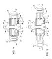
- FIG. 1shows a front cross-sectional view of one embodiment of the buckle assembly according to the invention
- FIG. 2shows the buckle assembly of FIG. 1 in a released position
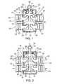
- FIG. 3shows a front cross-sectional view of another embodiment of the buckle assembly according to the invention.
- FIG. 4shows the buckle assembly of FIG. 3 in a released position
- FIG. 5shows a front cross-sectional view of another embodiment of the buckle assembly according to the invention.
- FIG. 6shows the buckle assembly of FIG. 5 in a released position
- FIG. 7shows a front cross-sectional view of another embodiment of the buckle assembly according to the invention.
- FIG. 8shows the buckle assembly of FIG. 7 in a released position
- FIG. 9shows a front cross-sectional view of another embodiment of the buckle assembly according to the invention.
- FIG. 10shows the buckle assembly of FIG. 9 in a released position
- FIG. 11shows a front cross-sectional view of another embodiment of the buckle assembly according to the invention.
- FIG. 12shows the buckle assembly of FIG. 11 in a released position.
- FIG. 1shows a first embodiment of the buckle assembly according to the invention.
- Buckle assembly 10comprises a housing 11 with four side openings 12 through which four male buckle portions 20 are inserted.
- Each male buckle portion 20has strap retaining bars 22 , 23 and a locking leg 24 .
- Each locking leg 24has a locking pawl 25 located on its distal end.
- Inside housing 11is an actuating device 30 , which is held in place by springs 36 .
- Actuating device 30consists of four latching mechanisms in the form of arms 33 which have catches 34 . Catches 34 interact with locking pawls 25 to lock male buckle portions 20 inside housing 11 when male buckle portions 20 are inserted through side openings 12 .
- FIGS. 3 and 4An alternative embodiment of the buckle assembly is shown in FIGS. 3 and 4 .
- there are two male buckle portions 50each with strap securing bars 51 , 52 .
- Male buckle portions 50each have two locking legs 53 with a locking pawl 54 on the end of each locking leg.
- Actuating device 42is mounted inside housing 40 and protrudes through both the bottom and top of housing 40 .
- Actuating device 42has a central leg 47 onto which side arms with latching mechanism 43 are disposed on the top side, and shoulder elements 46 are disposed on the bottom side.
- a handle 44is located at the top of actuating device 42 .
- Inserting male buckle portions 50 into housing 40causes locking pawls 54 to snap into engagement with latching mechanism 43 on the top, and catch 41 on housing 40 to engage on the bottom, as shown in FIG. 3 .
- handle 44is pulled upward, as shown in FIG. 4 , which moves latching mechanism 43 out of engagement with the upper locking leg 53 .
- shoulder elements 46press upward on locking pawl 54 on the lower locking leg 53 and force male buckle portions 50 outward and away from housing 40 .
- Actuating device 42is maintained within housing 40 via guide rails 48 on housing 40 . Actuating device 42 can slide up and down but is prevented from lateral movement by guide rails 48 .
- FIGS. 3 and 4One advantage of the embodiment shown in FIGS. 3 and 4 is that multiple buckle assemblies can be connected together and actuated simultaneously with a single pull.
- handle 44 on one actuating mechanismis connected to a bottom of an adjacent actuating mechanism via aperture 45 by any conventional means, such as a screw. This way, pulling upward on a first actuating mechanism will also pull any connected actuating mechanisms and release all male buckle portions for any of the connected assemblies.
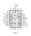
- FIGS. 5 and 6Yet another embodiment of the buckle assembly is shown in FIGS. 5 and 6 .
- Actuating device 65is mounted entirely within housing 60 and is actuated by pulling a cable 80 that extends through an aperture in the top of housing 60 .
- Cable 80is covered by a cable sheath 81 on the exterior of housing 60 and slides within cable sheath 81 when cable 80 is pulled.
- Springs 61keeps actuating device 65 biased in housing 60 so that male buckle portions 70 snap into actuating device 65 and are retained there until cable 80 is pulled.
- Latching mechanisms 67 on arms 66interact with locking pawls 74 on the upper legs of male buckle portions 70 and stops 62 catch on locking pawls 74 of the lower legs of male buckle portions 70 .
- Male buckle portions 70are guided into housing 60 via guides 78 , which receive central leg 77 of each of male buckle portions 70 . This prevents male buckle portions 70 from being inserted in a tilted or off-center manner, and ensures secure locking of male buckle portions 70 in housing 60 .
- Actuating device 65is retained in place inside housing 60 by a set of guide pins 63 that extend through a slot 82 in actuating device 65 . Actuating device 65 can slide along guide pins 63 , but is prevented from lateral movement.
- Pulling cable 80causes actuating device to move upward, thus freeing locking pawls 74 from latching mechanisms 67 and stops 62 .
- shoulders 68slide along locking pawls 74 and push male buckle portions out of housing 60 , as shown in FIG. 6 .
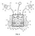
- FIGS. 7 and 8Another embodiment is shown in FIGS. 7 and 8 .
- two male buckle portions 70are inserted into housing 60 , and are held in place by latching mechanisms 89 on the top and catches 41 on the bottom, which interact with locking pawls 74 on locking legs 73 of male buckle portions 70 .
- Pulling upward on handle 32pulls cable 80 disposed inside cable sheath 81 and moves actuating device 85 upward.
- Thiscauses locking legs 73 of male buckle portions 70 inside housing 60 to be released from latching mechanisms 89 and catches 41 , in the same manner as described above with respect to the embodiment of FIGS. 5 and 6 .
- shoulders 86slide along locking pawls 74 of the lower locking leg and force male buckle portions 70 out of housing 60 .
- Guide pins 63which extend through slot 82 in actuating device 85 keep actuating device 85 oriented properly in housing 60 .
- two additional male buckle portions 170are also moved by pulling on handle 32 .
- male buckle portions 170are connected to a cable 92 inside cable sheath 93 .
- Cable 92is connected to one end of a lever 90 mounted on a fulcrum 91 inside housing 60 .
- Pulling handle 32causes shoulders 95 of actuating mechanism 85 to press against levers 90 and cause levers 90 to rotate, thus forcing the distal ends of levers 90 downward, as shown in FIG. 8 .
- Buckle 170can be configured so that pulling on cable 92 acts to release buckles 170 from a corresponding female buckle portion. The exact mechanism for this release is described in U.S.
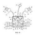
- FIGS. 9 and 10Yet another embodiment of the invention is shown in FIGS. 9 and 10 .
- This embodimentis similar to the embodiment shown in FIGS. 7 and 8 , except that instead of levers 90 , curved cable guides 99 are mounted inside housing 60 . Cables 92 are connected directly to actuating device 85 and extend around cable guides 99 . Pulling upward on handle 32 forces male buckle portions 70 out of housing 60 in the same manner as described above with respect to the previous embodiments. In addition, pulling upward on handle 32 also pulls cables 92 , which slide around cable guides 99 . This pulling motion thus also pulls male buckle portions 170 and allows them to be released from a corresponding female buckle portion.
- FIGS. 7-10are useful on items like a tactical cut-away vest that must be removed quickly and easily.
- male buckle portions 70could hold the lower part of the vest together via straps on male buckle portions 70
- male buckle portions 170could be used to secure the shoulder sections of the vest together when attached to corresponding female buckle portions. Pulling on handle 32 would then release all four buckle portions at the same time to allow the two sides of the vest to separate from each other.
- FIGS. 11 and 12Yet another embodiment is shown in FIGS. 11 and 12 .
- This embodimentis similar to the embodiment shown in FIGS. 3 and 4 , except that there are no latching mechanisms on actuating device 42 .
- there are two male buckle portions 50each with strap securing bars 51 , 52 .
- Male buckle portions 50each have two locking legs 53 with a locking pawl 54 on the end of only the bottom locking leg, which interacts with catch 41 on housing 40 .
- Actuating device 42is mounted inside housing 40 and protrudes through both the bottom and top of housing 40 .
- Actuating device 42has a central leg 47 onto which side arms are disposed on the top side, and shoulder elements 46 are disposed on the bottom side.
- a handle 44is located at the top of actuating device 42 .
- Inserting male buckle portions 50 into housing 40causes locking pawls 54 on the bottom legs 53 to snap into engagement with catch 41 on housing 40 , as shown in FIG. 11 .
- handle 44is pulled upward, as shown in FIG. 12 , which moves shoulder elements 46 press upward on locking pawl 54 on the lower locking leg 53 to clear catch 41 and force male buckle portions 50 outward and away from housing 40 .
Landscapes
- Buckles (AREA)
Abstract
Description
Claims (16)
Priority Applications (1)
| Application Number | Priority Date | Filing Date | Title |
|---|---|---|---|
| US12/807,384US8181318B2 (en) | 2010-09-03 | 2010-09-03 | Buckle assembly |
Applications Claiming Priority (1)
| Application Number | Priority Date | Filing Date | Title |
|---|---|---|---|
| US12/807,384US8181318B2 (en) | 2010-09-03 | 2010-09-03 | Buckle assembly |
Publications (2)
| Publication Number | Publication Date |
|---|---|
| US20120054993A1 US20120054993A1 (en) | 2012-03-08 |
| US8181318B2true US8181318B2 (en) | 2012-05-22 |
Family
ID=45769561
Family Applications (1)
| Application Number | Title | Priority Date | Filing Date |
|---|---|---|---|
| US12/807,384ActiveUS8181318B2 (en) | 2010-09-03 | 2010-09-03 | Buckle assembly |
Country Status (1)
| Country | Link |
|---|---|
| US (1) | US8181318B2 (en) |
Cited By (13)
| Publication number | Priority date | Publication date | Assignee | Title |
|---|---|---|---|---|
| US20110126387A1 (en)* | 2008-05-22 | 2011-06-02 | Paul Carter | Release Mechanism |
| US20120000004A1 (en)* | 2009-03-13 | 2012-01-05 | THF Innovation Pty Ltd. | Quick release garment |
| US20120030852A1 (en)* | 2010-08-03 | 2012-02-09 | Joseph Anscher | Multiple buckle release system |
| US20130307255A1 (en)* | 2011-04-02 | 2013-11-21 | Suzhou Eagle Electric Vehicle Manafacturing Co., Ltd. | Five-point safety belt and safety belt unlocking mechanism |
| USD717694S1 (en) | 2013-09-05 | 2014-11-18 | National Molding, Llc | Release mechanism for a buckle assembly |
| US9003947B1 (en) | 2013-11-20 | 2015-04-14 | National Molding, Llc | Holder for body mounted armor |
| US9038251B1 (en)* | 2013-10-02 | 2015-05-26 | National Molding, Llc. | Quick release buckle |
| US9354023B1 (en)* | 2013-11-20 | 2016-05-31 | National Molding, Llc. | Holder for body mounted armor |
| US9743719B2 (en) | 2013-10-02 | 2017-08-29 | National Molding, Llc. | Quick release buckle |
| US9752854B1 (en) | 2013-11-20 | 2017-09-05 | National Molding, Llc. | Holding for body mounted armor |
| US10104943B2 (en)* | 2014-07-07 | 2018-10-23 | Abbas Haider | Pull and release latch |
| US10485306B1 (en) | 2018-05-10 | 2019-11-26 | Duraflex Hong Kong Limited | Quick release system for body armor |
| US11814124B1 (en)* | 2019-06-03 | 2023-11-14 | Jelani Nkosi James | Securement apparatus for connecting riders together on a vehicle |
Families Citing this family (4)
| Publication number | Priority date | Publication date | Assignee | Title |
|---|---|---|---|---|
| US8732918B2 (en)* | 2008-05-22 | 2014-05-27 | Paul Carter | System and method for quick release |
| US9125458B2 (en)* | 2012-06-06 | 2015-09-08 | Illinois Tool Works Inc. | Multi-directional buckle assembly |
| US11369087B2 (en)* | 2019-06-20 | 2022-06-28 | Jason Smith | Remote release buckle |
| WO2024080944A1 (en)* | 2022-10-12 | 2024-04-18 | Samsun Yurt Savunma Sanayi̇ Ve Ti̇caret Anoni̇m Şi̇rketi̇ | A multi-purpose tactical uniform lock that is easily attached and detached |
Citations (30)
| Publication number | Priority date | Publication date | Assignee | Title |
|---|---|---|---|---|
| DE1849648U (en) | 1961-10-11 | 1962-04-05 | Tig Tech Industrieprodukte G M | BULLETPROOF FLYING VEST. |
| US3200463A (en) | 1962-12-10 | 1965-08-17 | Capewell Mfg Company | Quick-release connector |
| US5086548A (en)* | 1989-09-11 | 1992-02-11 | Kabushiki Kaisha Tokai-Rika-Denki-Seisakusho | Buckle device for seatbelt system |
| US5275437A (en)* | 1991-02-20 | 1994-01-04 | Trw Repa Gmbh | Actuating means for a buckle in a safety belt system |
| US5465472A (en) | 1993-10-16 | 1995-11-14 | Ykk Corporation | Buckle |
| US5511856A (en)* | 1992-06-12 | 1996-04-30 | Indiana Mills & Manufacturing, Inc. | Cable activated harness retractor for child seat |
| US5604964A (en)* | 1995-03-28 | 1997-02-25 | Nifco, Inc. | Buckle |
| US5832573A (en) | 1996-11-14 | 1998-11-10 | Down East, Inc. | Quick release buckle assembly |
| US6148486A (en)* | 1997-12-24 | 2000-11-21 | Uehara; Ryoichiro | Belt mounting structure of synthetic resin buckle |
| US6170133B1 (en)* | 1998-03-20 | 2001-01-09 | Ykk Corporation | Buckle |
| US6363590B1 (en)* | 1999-12-16 | 2002-04-02 | Taiwan Industrial Fastener Corporation | Safety buckle with buffer means |
| US6487761B2 (en) | 2001-01-17 | 2002-12-03 | Charles E. Van Tassel | Quick release buckle for divers |
| US6769137B2 (en) | 2001-10-24 | 2004-08-03 | D'annunzio Timothy B. | Cutaway vests |
| US6796007B1 (en)* | 2003-04-29 | 2004-09-28 | Joseph Anscher | Buckle assembly |
| US7047570B2 (en) | 2003-07-08 | 2006-05-23 | Eagle Industries Unlimited, Inc. | Cut away vest |
| US7073234B2 (en) | 2002-02-14 | 2006-07-11 | Aqua Lung America, Inc. | Quick-release buckle |
| US7096545B2 (en) | 2003-04-11 | 2006-08-29 | Ykk Corporation | Buckle |
| US20070283539A1 (en)* | 2006-06-13 | 2007-12-13 | Elsa Angelina Caterina Pezza | Safety strap buckle, in particular for automotive child safety seats |
| US7360287B2 (en)* | 2003-06-26 | 2008-04-22 | Sabelt S.P.A. | Coupling device for restraining belts, particularly for children's safety seats for motor vehicles |
| WO2008094280A2 (en) | 2006-06-09 | 2008-08-07 | Dovner Edward R | Protective garment system with weight transfer elements |
| US7424748B1 (en) | 2006-06-06 | 2008-09-16 | Eagle Industries Unlimited, Inc. | Quick release system for armor plates in a ballistic resistant vest and method |
| US20090038126A1 (en)* | 2007-08-08 | 2009-02-12 | Key Safety Systems, Inc. | Seat belt buckle |
| US20090038125A1 (en)* | 2007-08-07 | 2009-02-12 | Wu Wen-Yuan | Seatbelt Buckle for Use in Vehicle |
| WO2009047790A2 (en) | 2007-10-08 | 2009-04-16 | Mku Pvt Ltd | Quickly releasable vest |
| US7520036B1 (en)* | 2003-07-11 | 2009-04-21 | Amsafe Commercial Products, Inc. | Multi-point buckle for restraint system |
| DE102007058124A1 (en) | 2007-11-30 | 2009-06-04 | Mehler Vario System Gmbh | Lock for connecting e.g. strap with connecting piece in protection vest, has actuation unit designed as remote actuation unit and in actuation connection with locking element by traction unlocking mechanism |
| US20100101060A1 (en)* | 2008-10-24 | 2010-04-29 | Tk Holdings Inc. | Remotely actuated seat belt buckle |
| US20100237112A1 (en)* | 2009-03-20 | 2010-09-23 | Bp Children's Products Hk Co., Limited | Harness Fastener System for Child Carrier Device |
| US20110162177A1 (en)* | 2009-12-23 | 2011-07-07 | Bae Systems Aerospace & Defense Group Inc. | Quick Release Buckle with Dual Release |
| US20110247180A1 (en)* | 2010-04-07 | 2011-10-13 | Ykk Corporation Of America | Release System |
- 2010
- 2010-09-03USUS12/807,384patent/US8181318B2/enactiveActive
Patent Citations (31)
| Publication number | Priority date | Publication date | Assignee | Title |
|---|---|---|---|---|
| DE1849648U (en) | 1961-10-11 | 1962-04-05 | Tig Tech Industrieprodukte G M | BULLETPROOF FLYING VEST. |
| US3200463A (en) | 1962-12-10 | 1965-08-17 | Capewell Mfg Company | Quick-release connector |
| US5086548A (en)* | 1989-09-11 | 1992-02-11 | Kabushiki Kaisha Tokai-Rika-Denki-Seisakusho | Buckle device for seatbelt system |
| US5275437A (en)* | 1991-02-20 | 1994-01-04 | Trw Repa Gmbh | Actuating means for a buckle in a safety belt system |
| US5511856A (en)* | 1992-06-12 | 1996-04-30 | Indiana Mills & Manufacturing, Inc. | Cable activated harness retractor for child seat |
| US5465472A (en) | 1993-10-16 | 1995-11-14 | Ykk Corporation | Buckle |
| US5604964A (en)* | 1995-03-28 | 1997-02-25 | Nifco, Inc. | Buckle |
| US5832573A (en) | 1996-11-14 | 1998-11-10 | Down East, Inc. | Quick release buckle assembly |
| US6148486A (en)* | 1997-12-24 | 2000-11-21 | Uehara; Ryoichiro | Belt mounting structure of synthetic resin buckle |
| US6170133B1 (en)* | 1998-03-20 | 2001-01-09 | Ykk Corporation | Buckle |
| US6363590B1 (en)* | 1999-12-16 | 2002-04-02 | Taiwan Industrial Fastener Corporation | Safety buckle with buffer means |
| US6487761B2 (en) | 2001-01-17 | 2002-12-03 | Charles E. Van Tassel | Quick release buckle for divers |
| US6769137B2 (en) | 2001-10-24 | 2004-08-03 | D'annunzio Timothy B. | Cutaway vests |
| US7073234B2 (en) | 2002-02-14 | 2006-07-11 | Aqua Lung America, Inc. | Quick-release buckle |
| US7096545B2 (en) | 2003-04-11 | 2006-08-29 | Ykk Corporation | Buckle |
| US6796007B1 (en)* | 2003-04-29 | 2004-09-28 | Joseph Anscher | Buckle assembly |
| US7360287B2 (en)* | 2003-06-26 | 2008-04-22 | Sabelt S.P.A. | Coupling device for restraining belts, particularly for children's safety seats for motor vehicles |
| US7047570B2 (en) | 2003-07-08 | 2006-05-23 | Eagle Industries Unlimited, Inc. | Cut away vest |
| US7243376B2 (en) | 2003-07-08 | 2007-07-17 | Eagle Industries Unlimited, Inc. | Cut away vest |
| US7520036B1 (en)* | 2003-07-11 | 2009-04-21 | Amsafe Commercial Products, Inc. | Multi-point buckle for restraint system |
| US7424748B1 (en) | 2006-06-06 | 2008-09-16 | Eagle Industries Unlimited, Inc. | Quick release system for armor plates in a ballistic resistant vest and method |
| WO2008094280A2 (en) | 2006-06-09 | 2008-08-07 | Dovner Edward R | Protective garment system with weight transfer elements |
| US20070283539A1 (en)* | 2006-06-13 | 2007-12-13 | Elsa Angelina Caterina Pezza | Safety strap buckle, in particular for automotive child safety seats |
| US20090038125A1 (en)* | 2007-08-07 | 2009-02-12 | Wu Wen-Yuan | Seatbelt Buckle for Use in Vehicle |
| US20090038126A1 (en)* | 2007-08-08 | 2009-02-12 | Key Safety Systems, Inc. | Seat belt buckle |
| WO2009047790A2 (en) | 2007-10-08 | 2009-04-16 | Mku Pvt Ltd | Quickly releasable vest |
| DE102007058124A1 (en) | 2007-11-30 | 2009-06-04 | Mehler Vario System Gmbh | Lock for connecting e.g. strap with connecting piece in protection vest, has actuation unit designed as remote actuation unit and in actuation connection with locking element by traction unlocking mechanism |
| US20100101060A1 (en)* | 2008-10-24 | 2010-04-29 | Tk Holdings Inc. | Remotely actuated seat belt buckle |
| US20100237112A1 (en)* | 2009-03-20 | 2010-09-23 | Bp Children's Products Hk Co., Limited | Harness Fastener System for Child Carrier Device |
| US20110162177A1 (en)* | 2009-12-23 | 2011-07-07 | Bae Systems Aerospace & Defense Group Inc. | Quick Release Buckle with Dual Release |
| US20110247180A1 (en)* | 2010-04-07 | 2011-10-13 | Ykk Corporation Of America | Release System |
Non-Patent Citations (1)
| Title |
|---|
| European Search Report dated Aug. 20, 2010. |
Cited By (18)
| Publication number | Priority date | Publication date | Assignee | Title |
|---|---|---|---|---|
| US20110126387A1 (en)* | 2008-05-22 | 2011-06-02 | Paul Carter | Release Mechanism |
| US8490256B2 (en)* | 2008-05-22 | 2013-07-23 | Paul Carter | Release mechanism |
| US20120000004A1 (en)* | 2009-03-13 | 2012-01-05 | THF Innovation Pty Ltd. | Quick release garment |
| US9115959B2 (en)* | 2009-03-13 | 2015-08-25 | Thf Innovation Pty Ltd | Quick release garment |
| US20120030852A1 (en)* | 2010-08-03 | 2012-02-09 | Joseph Anscher | Multiple buckle release system |
| US20130307255A1 (en)* | 2011-04-02 | 2013-11-21 | Suzhou Eagle Electric Vehicle Manafacturing Co., Ltd. | Five-point safety belt and safety belt unlocking mechanism |
| US8979130B2 (en)* | 2011-04-02 | 2015-03-17 | Suzhou Eagle Electric Vehicle Manufacturing Co., Ltd. | Five-point safety belt and safety belt unlocking mechanism |
| USD717694S1 (en) | 2013-09-05 | 2014-11-18 | National Molding, Llc | Release mechanism for a buckle assembly |
| US9038251B1 (en)* | 2013-10-02 | 2015-05-26 | National Molding, Llc. | Quick release buckle |
| US9743719B2 (en) | 2013-10-02 | 2017-08-29 | National Molding, Llc. | Quick release buckle |
| US9003947B1 (en) | 2013-11-20 | 2015-04-14 | National Molding, Llc | Holder for body mounted armor |
| US9354023B1 (en)* | 2013-11-20 | 2016-05-31 | National Molding, Llc. | Holder for body mounted armor |
| US9752854B1 (en) | 2013-11-20 | 2017-09-05 | National Molding, Llc. | Holding for body mounted armor |
| US10104943B2 (en)* | 2014-07-07 | 2018-10-23 | Abbas Haider | Pull and release latch |
| US10485306B1 (en) | 2018-05-10 | 2019-11-26 | Duraflex Hong Kong Limited | Quick release system for body armor |
| CN112236642A (en)* | 2018-05-10 | 2021-01-15 | 力顿钮扣配件(深圳)有限公司 | Rapid release system for body armor |
| CN112236642B (en)* | 2018-05-10 | 2021-09-14 | 力顿钮扣配件(深圳)有限公司 | Rapid release system for body armor |
| US11814124B1 (en)* | 2019-06-03 | 2023-11-14 | Jelani Nkosi James | Securement apparatus for connecting riders together on a vehicle |
Also Published As
| Publication number | Publication date |
|---|---|
| US20120054993A1 (en) | 2012-03-08 |
Similar Documents
| Publication | Publication Date | Title |
|---|---|---|
| US8181318B2 (en) | Buckle assembly | |
| US8572820B2 (en) | Dual release buckle | |
| US8191213B2 (en) | Quick release buckle assembly | |
| US5774956A (en) | High-security buckle | |
| US6311374B1 (en) | High security buckle assembly | |
| US8196273B2 (en) | Quick release buckle assembly | |
| US8281464B2 (en) | Buckle | |
| US20100313392A1 (en) | Quick release buckle assembly | |
| US7600302B2 (en) | Safety buckle for child seat and the like | |
| US20070137009A1 (en) | Buckle assembly | |
| US9332811B2 (en) | Webbing buckle with release mechanism | |
| AU2016201891B2 (en) | Quick release garment | |
| US20180049522A1 (en) | Non-Directional Instant locking fastner | |
| US9468781B2 (en) | Fastening device for straps | |
| US10791803B2 (en) | Release lever buckle | |
| US8464406B2 (en) | Quick release buckle assembly | |
| EP3752788B1 (en) | Quick release system for body armor | |
| US10349706B2 (en) | Releasable connecting device | |
| US7681288B1 (en) | Structure and material for a child resistant buckle | |
| KR102069786B1 (en) | Locking of device | |
| US20110197399A1 (en) | Release System | |
| TWM675591U (en) | Buckles and buckle assemblies |
Legal Events
| Date | Code | Title | Description |
|---|---|---|---|
| AS | Assignment | Owner name:NATIONAL MOLDING LLC, FLORIDA Free format text:ASSIGNMENT OF ASSIGNORS INTEREST;ASSIGNOR:ANSCHER, JOSEPH;REEL/FRAME:028024/0949 Effective date:20120404 | |
| STCF | Information on status: patent grant | Free format text:PATENTED CASE | |
| AS | Assignment | Owner name:NATIONAL MOLDING-DURAFLEX, LLC, FLORIDA Free format text:ASSIGNMENT OF ASSIGNORS INTEREST;ASSIGNOR:NATIONAL MOLDING LLC;REEL/FRAME:028457/0390 Effective date:20120627 | |
| AS | Assignment | Owner name:TEXAS CAPITAL BANK, NATIONAL ASSOCIATION, TEXAS Free format text:SECURITY AGREEMENT;ASSIGNOR:NATIONAL MOLDING, LLC;REEL/FRAME:029990/0001 Effective date:20130311 | |
| FPAY | Fee payment | Year of fee payment:4 | |
| AS | Assignment | Owner name:TEXAS CAPITAL BANK, NATIONAL ASSOCIATION, TEXAS Free format text:SECURITY INTEREST;ASSIGNOR:NATIONAL MOLDING, LLC;REEL/FRAME:039417/0697 Effective date:20160715 | |
| MAFP | Maintenance fee payment | Free format text:PAYMENT OF MAINTENANCE FEE, 8TH YR, SMALL ENTITY (ORIGINAL EVENT CODE: M2552); ENTITY STATUS OF PATENT OWNER: SMALL ENTITY Year of fee payment:8 | |
| AS | Assignment | Owner name:NATIONAL MOLDING, LLC, FLORIDA Free format text:RELEASE BY SECURED PARTY;ASSIGNOR:TEXAS CAPITAL BANK;REEL/FRAME:064740/0031 Effective date:20230828 Owner name:TAGLICH PRIVATE EQUITY, LLC, NEW YORK Free format text:SECURITY INTEREST;ASSIGNORS:NATIONAL MOLDING, LLC;NATIONAL MOLDING - DURAFLEX, LLC;REEL/FRAME:064739/0644 Effective date:20230828 | |
| AS | Assignment | Owner name:BYLINE BANK, ILLINOIS Free format text:SECURITY INTEREST;ASSIGNORS:NATIONAL MOLDING, LLC;NATIONAL MOLDING - DURAFLEX, LLC;REEL/FRAME:064758/0314 Effective date:20230828 | |
| AS | Assignment | Owner name:SOUTHFIELD MEZZANINE CAPITAL LP, CONNECTICUT Free format text:SECURITY INTEREST;ASSIGNOR:NATIONAL MOLDING - DURAFLEX, LLC;REEL/FRAME:064793/0897 Effective date:20230828 | |
| MAFP | Maintenance fee payment | Free format text:PAYMENT OF MAINTENANCE FEE, 12TH YR, SMALL ENTITY (ORIGINAL EVENT CODE: M2553); ENTITY STATUS OF PATENT OWNER: SMALL ENTITY Year of fee payment:12 |