US8180712B2 - Methods and apparatus for determining whether a media presentation device is in an on state or an off state - Google Patents
Methods and apparatus for determining whether a media presentation device is in an on state or an off stateDownload PDFInfo
- Publication number
- US8180712B2 US8180712B2US12/242,337US24233708AUS8180712B2US 8180712 B2US8180712 B2US 8180712B2US 24233708 AUS24233708 AUS 24233708AUS 8180712 B2US8180712 B2US 8180712B2
- Authority
- US
- United States
- Prior art keywords
- fuzzy
- state
- score
- contribution
- value
- Prior art date
- Legal status (The legal status is an assumption and is not a legal conclusion. Google has not performed a legal analysis and makes no representation as to the accuracy of the status listed.)
- Active, expires
Links
Images


Classifications
- G—PHYSICS
- G06—COMPUTING OR CALCULATING; COUNTING
- G06N—COMPUTING ARRANGEMENTS BASED ON SPECIFIC COMPUTATIONAL MODELS
- G06N5/00—Computing arrangements using knowledge-based models
- G06N5/04—Inference or reasoning models
- G06N5/048—Fuzzy inferencing
- G—PHYSICS
- G06—COMPUTING OR CALCULATING; COUNTING
- G06F—ELECTRIC DIGITAL DATA PROCESSING
- G06F7/00—Methods or arrangements for processing data by operating upon the order or content of the data handled
- G06F7/02—Comparing digital values
- G06F7/023—Comparing digital values adaptive, e.g. self learning
- H—ELECTRICITY
- H04—ELECTRIC COMMUNICATION TECHNIQUE
- H04H—BROADCAST COMMUNICATION
- H04H60/00—Arrangements for broadcast applications with a direct linking to broadcast information or broadcast space-time; Broadcast-related systems
- H04H60/29—Arrangements for monitoring broadcast services or broadcast-related services
- H04H60/32—Arrangements for monitoring conditions of receiving stations, e.g. malfunction or breakdown of receiving stations
- H—ELECTRICITY
- H04—ELECTRIC COMMUNICATION TECHNIQUE
- H04H—BROADCAST COMMUNICATION
- H04H2201/00—Aspects of broadcast communication
- H04H2201/90—Aspects of broadcast communication characterised by the use of signatures
- H—ELECTRICITY
- H04—ELECTRIC COMMUNICATION TECHNIQUE
- H04H—BROADCAST COMMUNICATION
- H04H60/00—Arrangements for broadcast applications with a direct linking to broadcast information or broadcast space-time; Broadcast-related systems
- H04H60/56—Arrangements characterised by components specially adapted for monitoring, identification or recognition covered by groups H04H60/29-H04H60/54
- H04H60/58—Arrangements characterised by components specially adapted for monitoring, identification or recognition covered by groups H04H60/29-H04H60/54 of audio
Definitions
- the present disclosurerelates generally to audience measurement, and more particularly, to methods and apparatus for determining whether a media presentation device is in an on state or an off state.
- Media ratings and other audience metering informationare typically generated by collecting media exposure information from a group of statistically selected households.
- Each of the statistically selected householdstypically has a data logging and processing unit commonly referred to as a “home unit,” “meter” or “audience measurement device.”
- the data logging and processing functionalitymay be distributed among a single home unit and multiple site units, where one site unit may be provided for each media presentation device or media presentation area.
- the home unit(or the combination of the home unit and the site units) includes sensors to gather data from the monitored media presentation devices (e.g., audio-video (AV) devices) at the selected site.
- AVaudio-video
- HDMI-CECHigh-Definition Multimedia Interface-Consumer Electronic Control
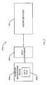
- FIG. 1is a block diagram of an example media monitoring system to detect an on state or an off state of a media presentation device.
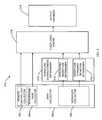
- FIG. 2is a block diagram of an example on/off identifier implemented in an example back office as illustrated in FIG. 1 .
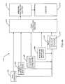
- FIG. 3is a more detailed illustration of the example on/off identifier of FIGS. 1 and 2 .
- FIG. 4Ais a detailed illustration of an example fuzzy logic engine that may be used to implement the example on/off identifier of FIG. 3
- FIG. 4Bis a representation of data flow through an example buffer during operation of an example fuzzy contribution analyzer implemented in the example fuzzy logic engine of FIG. 4A .
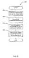
- FIG. 5is a flow diagram representative of example machine readable instructions that may be executed to implement the example on/off identifier of FIGS. 1-3 and/or 4 .
- FIG. 6is a flow diagram representative of example machine readable instructions that may be executed to implement an example standard deviation determiner for inclusion in the example on/off identifier of FIG. 3 .
- FIG. 7is a flow diagram representative of example machine readable instructions that may be executed to implement an example integrated magnitude determiner for inclusion in the example on/off identifier of FIG. 3 .
- FIG. 8is a flow diagram representative of example machine readable instructions that may be executed to implement an example gain evaluator for inclusion in the example fuzzy logic engine of FIG. 4A .
- FIG. 9is a flow diagram representative of example machine readable instructions that may be executed to implement an example remote control hint evaluator for inclusion in the example fuzzy logic engine of FIG. 4A .
- FIG. 10is a flow diagram representative of example machine readable instructions that may be executed to implement an example magnitude standard deviation evaluator for inclusion in the example fuzzy logic engine of FIG. 4A .
- FIG. 11is a flow diagram representative of example machine readable instructions that may be executed to implement an example integrated magnitude evaluator for inclusion in the example fuzzy logic engine of FIG. 4A .
- FIGS. 12A and 12Bare collectively flow diagrams representative of example machine readable instructions that may be executed to implement an example input convergence evaluator for inclusion in the example fuzzy logic engine of FIG. 4A .
- FIG. 13is a flow diagram representative of example machine readable instructions that may be executed to implement an example stage one fuzzy logic evaluator for inclusion in the example fuzzy logic engine of FIG. 4A .
- FIGS. 14A and 14Bare flow diagrams representative of example machine readable instructions that may be executed to implement an example stage two fuzzy logic evaluator for inclusion in the example fuzzy logic engine of FIG. 4A .
- FIG. 15is a flow diagram representative of example machine readable instructions that may be further executed in conjunction with the example machine readable instructions of FIGS. 13 and 14 to implement an example outlier removal method within the fuzzy logic engine of FIG. 4A .
- FIG. 16is a representation of an example output generated by an example microphone gain evaluator implemented in the example on/off identifier of FIG. 3 .
- FIG. 17is a representation of an example output generated by the example standard deviation determiner of FIG. 3 executing the example machine accessible instructions of FIG. 9 .
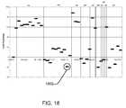
- FIG. 18is a representation of an example output generated by the example integrated magnitude determiner of FIG. 3 executing the example machine accessible instructions of FIG. 10 .
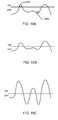
- FIGS. 19A-19Care representations of example outputs generated by the example fuzzy logic engine of FIG. 3 executing the example machine accessible instructions of FIGS. 13-15 .
- FIG. 20is a representation of an example output generated by the example on/off identifier of FIGS. 1-2 executing the example machine accessible instructions of FIGS. 5-15 .
- FIG. 21is a block diagram of an example processor system that may be used to execute the example machine accessible instructions of FIGS. 5-15 to implement the example system and/or apparatus of FIGS. 1-4A .
- Metering dataproviding an accurate representation of the exposure to media content of persons in metered households is useful in generating media ratings of value to advertisers and/or producers of media content. Generating accurate metering data has become difficult as the media presentation devices have become more complex in functionality and interoperability. Manufacturers are developing standardized interfaces to ease the set-up and connection of these devices (e.g., such as HDMI-CEC). However, the media presentation devices may still be powered independently. For example, a media source device (e.g., a set top box) may be in an on state and providing media content to a media presentation device (e.g., a television) that is in an off state.
- a media source devicee.g., a set top box
- a media presentation devicee.g., a television
- the sensorsmay detect audio signals associated with the operation of televisions (e.g., 15.75 kHz signals from the power unit (e.g., the flyback converter) of a CRT display), video signals (e.g. light levels), electromagnetic fields associated with a media presentation device and/or remote control signals (e.g., radio frequency or infrared signals).
- audio signals associated with the operation of televisionse.g., 15.75 kHz signals from the power unit (e.g., the flyback converter) of a CRT display
- video signalse.g. light levels
- electromagnetic fields associated with a media presentation devicee.g., radio frequency or infrared signals.
- Audience measurement devicesutilizing these methods require additional components designed to detect the on state or the off state of the media devices (e.g., light level detectors, electromagnetic field detectors, etc.), additional processor capacity to process the additional data (e.g., detecting and filtering a 15.75 kHz signal from an audio signal) and/or additional memory to store a greater amount of data.
- additional processor capacityto process the additional data (e.g., detecting and filtering a 15.75 kHz signal from an audio signal) and/or additional memory to store a greater amount of data.
- Such metering devicesmay be large, contain multiple sensing units, and/or be expensive to build, resulting from the need for additional sensors, processing power and memory.
- portable audience measurement devicesconfigured to capture data regarding media exposure (e.g., television viewing habits of person(s) in metered households) without the use of additional components (e.g., sensors, additional memory, etc) dedicated to sense the on state or off state of media presentation devices are disclosed herein. More specifically, the example methods and apparatus described herein may be used to identify the on state or the off state of media presentation devices (e.g., televisions, stereo receivers, etc.) from existing data collected by an audience measurement device over a time period of interest.
- media presentation devicese.g., televisions, stereo receivers, etc.
- Portable metering devicese.g., mailable meters which are the audience measurement devices designed to be sent to metering sites (e.g., households where at least one person elects to participate in an audience measurement panel)
- metering sitese.g., households where at least one person elects to participate in an audience measurement panel
- the meter and/or the data collected by the meterare sent to a back office where the collected data is processed to identify the media content detected in the metered household and to determine if such detected media content should be credited as having been presented to one or more audience members.
- One method of crediting media content as being presented to one or more audience membersis accomplished through examining signatures of captured signals (e.g., a captured audio signal and/or a captured video signal).
- a signaturemay be determined from an audio signal captured via a microphone of a meter regardless of whether a media presentation device was actively presenting media content.
- any audio signalsuch as the audio content of a television program or a conversation in a room containing the meter, may be processed to determine a signature.
- the signaturemay be used for crediting media content as having been presented in a metered environment if a match is found between the determined signature and an entry in a reference database.
- Crediting information corresponding to such signature matchesmay be used to determine whether a media presentation device is in the on state or the off state, but signature matches alone does not provide accurate results.
- a televisionmay be on and presenting media content without a signature match being found with the reference database, such as when the media content is being provided by a digital versatile disc (DVD).
- DVDdigital versatile disc
- an unmatched signaturee.g., corresponding to people talking in the room
- valid crediting informationprovides a strong inference that a media presentation device is in the on state or the off state
- factorse.g., signature characteristics, remote control hints and/or a gain of a microphone in a meter
- the example methods and apparatus described hereinobtain a signature, a gain associated with a microphone and/or hints associated with remote control events associated with the media presentation device as detected by an audience measurement device.
- a characteristic associated with the signatureis determined and analyzed to identify the on state or the off state of the monitored media presentation device.
- theis determined by (1) deriving a magnitude associated with the signature and integrating the derived magnitude over a period of time and/or (2) determining a standard deviation of a magnitude associated with the signature over a period of time.
- the example methods and apparatus described hereinmay identify whether the monitored media presentation device is in the on state or the off state based on the determined characteristic of the signature and/or a gain in a microphone of the audience measurement device that detected the media content. Alternatively or additionally, the example methods and apparatus may identify whether the media presentation device is in the on or the off state based on a hint from a remote control device monitored by the audience measurement device that detected the media content or by a second audience measurement device.
- the gain in the microphone of the audience measurement device, the hints derived from events reflecting the operation of a remote control device and/or the characteristic(s) of the signature magnitudeare analyzed with a fuzzy logic engine within an on/off identifier.
- the fuzzy logic enginestores a record representing the on state or the off state of the media presentation device over the metered period in an output database.
- a media content provider 102provides content to an audience via one or more information presentation devices, such as a set top box 104 and a television 106 .
- the components of the media presentation systemmay be coupled in any manner.
- the television 106is positioned in a monitored area 120 located within a household occupied by one or more people, represented by a person 110 , some or all of whom have agreed to participate in an audience measurement research study.
- the monitored area 120includes the area in which the television 106 is located and from which the one or more household member(s) 110 located in the monitored area 120 may view the television 106 .
- an audience measurement system 100is used to collect audience measurement data concerning media activity associated with the metered household.
- an audience measurement device 108is configured to collect media exposure information associated with one or more a media device(s) (e.g., the set top box 104 and the television 106 ) in the monitored area 120 .
- the exposure informationmay be collected via wired connection(s) to the media device(s) and/or without such wired connection(s) (e.g., by monitoring audio and/or other detectible events in the viewing area).
- the audience measurement device 108provides this exposure information, which may include detected codes associated with audio content, detected audio signals, collected signatures representative of detected audio signals, tuning and/or demographic information, etc. for evaluation in a back office 114 .
- the information collected by the audience measurement device 108may be conveyed to the back office 114 for evaluation by physically sending the audience measurement device 108 to the back office 114 for evaluation (e.g., transporting via a courier or the United States Postal Service) or, alternatively, via any other networking connection (e.g., an Ethernet connection, the Internet, a telephone line, etc.).
- the information collected in the audience measurement device 108is processed and stored in the back office 114 to produce ratings information.
- the back office 114includes an on/off identifier 116 to determine whether the media presentation device (e.g., the television 106 ) is in the on state or the off state and, thus, to determine whether media detected by the audience measurement device 108 should be counted as an audience exposure.
- the media content provider 102may convey the media content to a metered household via a cable network, a radio transmitter or one or more satellites.
- the media content providermay be a cable television provider distributing the television programs exclusively via a cable network or a satellite provider distributing media via satellite.
- the media content provider 102may transmit media signals in any suitable format, such as a National Television Standards Committee (NTSC) television signal format, a high definition television (HDTV) signal format, an Association of Radio Industries and Businesses (ARIB) television signal format, etc.
- NTSCNational Television Standards Committee
- HDMIhigh definition television
- ARIBAssociation of Radio Industries and Businesses
- One or more user-operated remote control devices 112allow a viewer (e.g., the household member 110 ) to send commands to the television 106 and/or STB 104 requesting presentation of specific media content or broadcast channels provided by the media content provider 102 .
- the remote control device(s) 112may be designed to communicate with only a subset of the media devices (e.g., the television 106 and/or the set top box 104 ) from a single manufacturer, or the remote control device(s) 112 may be a universal remote control configured to communicate with some or all of the media devices in the metered household.
- a universal remote control device 112may allow an audience member 110 to cause both the television 106 and the set top box 104 to enter an on state and to configure themselves such that the television 106 displays media content supplied via the set top box 104 .
- the audience measurement device 108is configured to collect information regarding the viewing behaviors of household members 110 by monitoring a non-acoustic signal (e.g., a video signal, an audio signal, an infrared remote control signal, etc.) and/or an acoustic signal (e.g., sound) within the monitored area 120 .
- a non-acoustic signale.g., a video signal, an audio signal, an infrared remote control signal, etc.
- an acoustic signale.g., sound
- the information collectedmay comprise an audio signal reflecting humanly audible and/or humanly inaudible sounds within the household recorded via a microphone coupled to or included in the audience measurement device 108 .
- the collected informationmay include signals (e.g., infrared, radio frequency, etc.) generated by a remote control device 112 .
- the audio recorded via the microphone of the audience measurement device 108may comprise audio signals from the monitored media presentation device (e.g., the television 106 ) and/or background noise from within the monitored area 120 .
- the remote control signals captured from the remote control device 112may contain control information (e.g., channel tuning commands, power on/off commands, etc.) to control the monitored media device(s) (e.g., the set top box 104 and/or the television 106 ).
- the captured audience measurement device datais conveyed (e.g., the audience measurement device 108 is physically sent to the back office, the data collected is transmitted electronically via an Ethernet connection, etc.) to the back office 114 for processing.
- the back office 114 of the illustrated exampleextracts a signature from the audio captured via the microphone of the audience measurement device 108 .
- One or more characteristics of the signaturesare then analyzed alone or in conjunction with other data as explained below to produce crediting information regarding programs presented by a monitored media presentation device (e.g., a radio, a stereo, a STB 104 , a television 106 , a game console, etc.).
- a monitored media presentation devicee.g., a radio, a stereo, a STB 104 , a television 106 , a game console, etc.
- the on/off identifier 116is implemented in the back office 114 and is configured to identify whether a media presentation device (e.g., the STB 104 and/or the television 106 ) is in an on state capable of actively presenting media content, or in an off state.
- a media presentation devicee.g., the STB 104 and/or the television 106
- the information regarding the on state or off state of the televisionis helpful in accurately processing the data captured by the audience measurement device 108 .
- the set top box 104may be in an on state such that the set top box 104 continues to receive and output media content provided by the media content provider 102 , while the television 106 may have been placed in an off state.
- the on/off identifier 116may be used to improve the accuracy of media exposure measurements and ratings derived therefrom by determining whether the media content was actually presented to the person 110 within the monitored area 120 .
- FIG. 2is a block diagram of an example system 200 implemented within the back office 114 for processing data when the example audience measurement device 108 and/or the data collected thereby is returned from a monitored area 120 .
- the example system 200allows the example on/off identifier 116 to access data gathered by the audience measurement device 108 to determine whether the media presentation device 104 , 106 was in the on state or the off state at the time the data was gathered.
- the audience measurement device 108collects data (e.g., ambient audio, audio signals, video signals, remote control signals, etc.) in the metered monitored area 120 . Subsequently the data is conveyed to the back office 114 to be utilized to generate media ratings information.
- datae.g., ambient audio, audio signals, video signals, remote control signals, etc.
- the audience measurement device 108 of the illustrated examplestores the captured data within a data file 202 and then transfers the captured data file 202 to an input database 204 implemented in the back office 114 .
- the datamay, for example, be conveyed to the back office 114 via electronic means (e.g., transferring via an Ethernet connection) or physical means (e.g., transporting the audience measurement device to the back office 114 ).
- the data stored within the input database 204is processed to create, for example, an audio signature for use in identifying media presented to the meter 108 and/or other information (e.g., tuning information, program identification codes, etc.) used to identify the media.
- audio signaturesmay be determined by the audience measurement device 108 and included in the data file 202 .
- the on/off identifier 116obtains data (e.g., the audio signal, the signature, a characteristic of the signature, the remote control event record(s), etc.) from the input database 204 to determine whether the media presentation device (e.g., the television 106 ) is in the on state or the off state.
- datae.g., the audio signal, the signature, a characteristic of the signature, the remote control event record(s), etc.
- the data captured by the audience measurement device 108may be stored in the data file 202 in any format (e.g., an American Standard Code for Information Interchange (ASCII) format, a binary format, a raw data format, etc.) for storing data on an electronic medium (e.g., a memory or a mass storage device).
- the electronic mediummay be a non-volatile memory (e.g., flash memory), a mass storage device (e.g., a disk drive), a volatile memory (e.g., static or dynamic random access memory) and/or any combination of the memory types.
- the data file 202may be stored in binary format on a random access memory 2108 communicatively coupled to a processor 2102 within a processor system 2100 , such as the processor system 2100 described in detail below in conjunction with FIG. 21 .
- the data captured by the audience measurement device 108may undergo some or all of the on/off detection processing (e.g., determining an audio signature) within the audience measurement device 108 itself, with the results being stored within the data file 202 within the audience measurement device 108 .
- the on/off detection processinge.g., determining an audio signature
- the example on/off identifier 116includes a data collector 306 , a signature characteristic determiner 310 , a fuzzy logic engine 316 and an output database 318 .
- the example data collector 306collects data (e.g., audio gain data, remote control hints, audio signatures, etc.) from the example input database 204 containing data obtained from, for example, the metered household 120 with the audience measurement device 108 .
- the signature characteristic determiner 310determines a characteristic of a signature obtained or determined from data in the input database 204 . For example, while the signature may be created during analysis in the back office 114 , the signature generation functionality may alternatively be integrated into the audience measurement device 108 and the resulting determined signature transferred to the example input database 204 (e.g., in the data file 202 ).
- the example fuzzy logic engine 316 of FIG. 3identifies whether the monitored media presentation device 104 , 106 is in the on state or the off state. An example implementation of the fuzzy logic engine 316 is described in detail below in conjunction with FIG. 4A .
- the on/off states identified by the fuzzy logic engine 316are stored in the output database 318 and made available for further analysis (e.g., of the data collected with the audience measurement device 108 ).
- the input database 204 and the output database 318are depicted as separate blocks within the back office 116 , their respective functionality may be incorporated within a single database or implemented with two or more databases.
- the input database 204 of FIG. 2 and the output database 318 of FIG. 3may be implemented as any type of database (e.g., a delimited flat file database or a structured query language (SQL) relational database) and stored utilizing any data storage method (e.g., a flash memory, a mass storage device, static or dynamic random access memory, etc.).
- SQLstructured query language
- the example data collector 306 of FIG. 3includes a remote control hint collector 302 , a microphone gain collector 304 and a signature collector 308 .
- the remote control hint collector 302collects hints associated with the operation of a remote control device (e.g., the remote control 112 ) within a metered viewing area (e.g., the metered monitored area 120 ) from the data file 202 .
- the hintsmay comprise any communication between the remote control device 112 and a monitored media device (e.g., the television 106 or the set top box 104 ) collected by an audience measurement device (e.g., the audience measurement device 108 ).
- the remote control 112may transmit commands entered by a person 110 to a television 106 via infrared signals.
- the audience measurement device 108 of the illustrated exampleis configured to capture the infrared commands and store the captured commands in the data file 202 ( FIG. 2 ) along with a time stamp indicating when the data was captured and stored.
- the remote control hint collector 302 of FIG. 3collects hints from the stored data to be analyzed by the fuzzy logic engine 316 .
- the microphone gain collector 304 of the illustrated examplecollects the gain information associated with a microphone of the audience measurement device 108 from the input database 204 for analysis by the fuzzy logic engine 316 .
- the microphonecaptures ambient audio present in the monitored area 120 .
- This audioincludes any audio output of the monitored media presentation device (e.g., the television 106 , a stereo (not shown), etc.) and other background noise (e.g., noise generated inside or outside the monitored area 120 , conversations among the household members, etc.).
- the gain applied to the microphoneis inversely proportional to the amplitude of the audio captured by the microphone. A high level of gain corresponds with a low level of ambient audio captured by the microphone. Conversely, a low level of gain corresponds with a high level of audio captured by the microphone.
- the audio signal output by the microphonemay be analyzed either in the audience measurement device 108 or in the back office 114 to determine an audio signature associated with media content presented by, for example, the television 106 .
- the signatureis then compared to reference signatures related to known programming provided by the media content provider 102 .
- the program associated with the reference signatureis identified as the media content presented by the television 108 and used in generating the media ratings data.
- the signature collector 308 of FIG. 3collects the audio signature from the input database 204 or from a signature generator (not shown) configured to process audio data stored in the input data base 204 .
- the signature characteristic determiner 310 of the illustrated exampledetermines a characteristic associated with the signature for analysis by the fuzzy logic engine 316 .
- the example signature characteristic determiner 310determines and/or derives the magnitude associated with the signature.
- the magnitude of a signaturewill vary over time, depending on the type of signature employed.
- the signaturereflects, for example, time domain variations of the audio signal captured by the audience measurement device 108 . Accordingly, the magnitude of the signature reflects variations of the audio amplitude.
- the signature characteristic determiner 310includes an integrated magnitude determiner 312 .
- the integrated magnitude determiner 312integrates the magnitude of the signature over the period of time.
- the integrated magnitudemay serve as the characteristic of the system utilized by the fuzzy logic engine 315 as described below.
- the signature magnitudemay be analyzed by the magnitude standard deviation determiner 314 to determine a standard deviation of the magnitude associated with the signature over the period of time.
- the standard deviationmay serve as the characteristic used by the fuzzy logic engine 316 .
- the fuzzy logic engine 316analyzes the data (e.g., the remote control hints, the microphone gain, the integrated magnitude of the signature and/or the standard deviation of the magnitude of the signature) collected by the data collector 306 and/or determined by the signature characteristic determiner 310 to identify whether the monitored media presentation device 104 , 106 is in the on state or the off state. Once the on state or off state is determined by the fuzzy logic engine 316 , the states are stored in the output database 318 . The states are stored in association with timestamps reflecting the time at which the corresponding signature occurred.
- the example on/off identifier 118utilizes a fuzzy logic engine 316 to determine the on state or the off state, but any other analysis method may be used.
- FIG. 3While an example manner of implementing the on/off identifier 116 of FIGS. 1-2 has been illustrated in FIG. 3 , one or more of the elements, blocks and/or devices illustrated in FIG. 3 may be combined, divided, re-arranged, omitted, eliminated and/or implemented in any other way. Further, the example data collector 306 , the example remote control hint collector 302 , the example microphone gain collector 304 , the example signature collector 308 , the example signature characteristic determiner 310 , the example integrated magnitude determiner 312 , the example magnitude standard deviation determiner 314 , the example fuzzy logic engine 316 , and/or the example output database 318 and/or, more generally, the on/off identifier 116 of FIGS.
- any of the example data collector 306 , the example remote control hint collector 302 , the example microphone gain collector 304 , the example signature collector 308 , the example signature characteristic determiner 310 , the example integrated magnitude determiner 312 , the example magnitude standard deviation determiner 314 , the example fuzzy logic engine 316 , the example output database 318 and/or, more generally, the example on/off identifier 116could be implemented by one or more circuit(s), programmable processor(s), application specific integrated circuit(s) (ASIC(s)), programmable logic device(s) (PLD(s)) and/or field programmable logic device(s) (FPLD(s)), etc.
- ASICapplication specific integrated circuit
- PLDprogrammable logic device
- FPLDfield programmable logic device
- At least one of the example data collector 306 , the example remote control hint collector 302 , the example microphone gain collector 304 , the example signature collector 308 , the example signature characteristic determiner 310 , the example integrated magnitude determiner 312 , the example magnitude standard deviation determiner 314 the example fuzzy logic engine 316 , and/or the example output database 318are hereby expressly defined to include a tangible medium such as a memory, DVD, CD, etc. storing the software and/or firmware.
- the on/off identifier of FIGS. 1-3may include one or more elements, processes and/or devices in addition to, or instead of, those illustrated in FIG. 3 , and/or may include more than one of any or all of the illustrated elements, processes and devices.
- FIG. 4AA block diagram depicting an example implementation of the example fuzzy logic engine 316 of FIG. 3 is illustrated in FIG. 4A .
- the example implementation of the fuzzy logic engine 316comprises a gain evaluator 402 , a remote control hint evaluator 404 , a standard deviation evaluator 406 , an integrated magnitude evaluator 408 , an input convergence evaluator 410 , a fuzzy contribution analyzer 412 and a crediting contribution analyzer 414 .
- the example fuzzy logic engine 316may be implemented using any desired combination of hardware, firmware and/or software. For example, one or more integrated circuits, processing devices, discrete semiconductor components and/or passive electronic components may be used to implement the example fuzzy logic engine 316 .
- the fuzzy logic engine 316is designed to analyze data collected via the audience measurement device 108 to determine whether a monitored media presentation device 104 , 106 was in an on state or an off state during time intervals within a monitored period. More specifically, the example audience measurement device 108 captures data (e.g., ambient audio, an audio signal, a remote control event record, etc.) at specific intervals (e.g., at 0.5 second increments) within the sampling period (e.g., one month) and stores the data in the data file 202 along with a timestamp corresponding with the time and date the data was captured. When transferred to the input database 204 , the timestamps remain associated with the corresponding captured data and, preferably, with the data derived therefrom.
- the fuzzy logic engine 316operates at an engine cycle corresponding to a time interval of, for example, 2 seconds, and separately evaluates the data captured for each engine cycle.
- each of the gain evaluator 402 , the remote control hint evaluator 404 , the standard deviation evaluator 406 , and the integrated magnitude evaluator 408evaluates the corresponding data collected by the data collector 306 and/or the signature characteristic(s) determined by the signature characteristic determiner 310 to generate a fuzzy contribution value.
- the gain evaluator 402generates a first fuzzy contribution value
- the remote control hint evaluator 404generates a second fuzzy contribution value
- the standard deviation evaluator 406generates a third fuzzy contribution value
- the input convergence evaluator 408generates a fourth fuzzy contribution value.
- the input convergence evaluator 410further evaluates each of the generated fuzzy contribution values (e.g., the first fuzzy contribution value, the second fuzzy contribution value, the third fuzzy contribution value and the fourth fuzzy contribution value) to determine whether the first, second, third and fourth fuzzy contribution values converge toward an indication of an on state (e.g., a positive value).
- the input convergence evaluator 410increments an audio test score value by the number of fuzzy contribution values that converge toward an on state. If the input convergence evaluator 410 determines that the evaluated first, second, third and fourth fuzzy contribution value converges towards an indication of an off state (e.g., a negative value), the audio test score is not incremented.
- the input convergence evaluator 410also analyzes the audio test score value to determine a fifth fuzzy contribution value associated with the number of evaluators that converge to (e.g., indicate) an on state.
- a new audio test scoreis calculated for each engine cycle.
- the audio test score and the first through fifth fuzzy contribution valuesare specific to each engine cycle.
- the first, second, third, fourth and fifth fuzzy contribution values generated by the gain evaluator 402 , the remote control hint evaluator 404 , the standard deviation evaluator 406 , the integrated magnitude evaluator 408 , and the input convergence evaluator 410 , respectively,are further analyzed to generate a record corresponding to the operating state(s) (e.g., the on state or the off state) of the monitored media presentation device during the example twenty four hour period.
- the operating state(s)e.g., the on state or the off state
- the example gain evaluator 402to evaluates a gain signal collected by the microphone gain collector 304 from the input database 204 ( FIG. 2 ).
- the gain evaluator 402outputs the first fuzzy contribution value to be analyzed by the fuzzy contribution analyzer 412 and by the input convergence evaluator 410 .
- the gain signal evaluated by the gain evaluator 402 of the illustrated examplemay comprise a range of values corresponding to a decibel (dB) range captured by a microphone over a period of time.
- a mailable meterprovided by The Nielsen Company, Inc., includes a microphone and is capable of applying a gain in the range of 0 dB to a maximum of 59.5 dB to the microphone in step increments of 0.5 dB per step.
- the gain evaluator 402examines the gain value for the engine cycle and generates a first fuzzy contribution value associated with the same engine cycle.
- the first fuzzy contribution valueis proportional to the gain input value in decibels.
- the gain evaluator 402generates a positive first fuzzy contribution value for small gain values, because small gain values imply a high volume audio signal. Conversely, a large gain value implies a low volume audio signal and, thus, the gain evaluator 402 generates a negative first fuzzy contribution value proportional to the gain input value in decibels.
- a microphonemay capture a high volume level when a person or persons are speaking within a metered viewing area (e.g., the monitored area 120 ) or when a media device (e.g., the television 106 ) is producing a high volume audio output. Consequently, the positive contribution of the gain value is limited to a maximum first fuzzy contribution value.
- a negative first fuzzy contribution value, corresponding to low volume levels,is not limited to a minimum value
- the remote control hint evaluator 404 of the illustrated exampleevaluates a series of remote control hints collected by the remote control hint collector 302 .
- the remote control hintscorrespond with, for example, commands issued by the participating viewer 110 to a monitored media device 104 and/or 106 via the remote control device 112 .
- Hintscontribute to the second fuzzy contribution value when a hint implies that the household member 110 was exposed to media content presented via the monitored media presentation device 104 , 106 .
- a hintimplies that the household member was exposed to media content presented via the media presentation device 104 , 106 when the hint occurs (1) within fifteen minutes of a second hint and (2) the second hint occurs within (plus or minus) fifteen minutes of the current evaluated time (e.g., the time associated with the current engine cycle).
- This ruleassumes that an active audience member will use the remote control to adjust the monitored media presentation device(s) 104 and/or 106 at least twice every 30 minutes.
- the standard deviation evaluator 406 of the illustrated exampleevaluates a standard deviation of a magnitude of a signature, as determined by, for example, the magnitude standard deviation determiner 314 over a time period (e.g., 15 seconds).
- the standard deviation of the magnitude of a signaturemay be highly variable, so the values output from the magnitude standard deviation determiner 314 represent lower bound standard deviation (LBSD) values calculated (e.g., filtered) over a period of time.
- LBSDlower bound standard deviation
- the standard deviation value of the current engine cycleis inserted into a lower bound filter.
- the example filtermay be implemented via a circular buffer (e.g., a first-in-first-out buffer with 120 elements) that outputs the minimum value contained within the buffer as the LBSD.
- the filtered output from the magnitude standard deviation determiner 314i.e., the LBSD
- the standard deviation evaluator 406determines the third fuzzy contribution value via an equation that may be determined through an examination of experimental results. For example, experimental results have indicated that an off state corresponds to very low standard deviation values (e.g., under 10) and an on state correlates to standard deviation values within an intermediate range (e.g., between 10 and 20).
- an example equationmay be inferred where an LBSD value greater than a threshold within the indication range of an on state, (e.g., +15) generate a positive third fuzzy contribution value, and an LBSD value less that the threshold generates a negative third fuzzy contribution value. Additionally, the experimental results demonstrated that an off state also corresponded to very high standard deviation values (e.g., greater than 35), so another example equation may incorporate this experimental result as an additional way to determine the third fuzzy contribution value.
- the integrated magnitude evaluator 408 of the illustrated exampleevaluates the signal output by the integrated magnitude determiner 312 .
- the output signal of the integrated magnitude determiner 312represents an integrated magnitude of a signature over a period of time.
- the integrated magnitude evaluator 408generates the fourth fuzzy contribution value by evaluating an first equation corresponding to the integrated magnitude value, for example, subtracting a first constant (e.g., 55) from the integrated magnitude value
- the first constantrepresents a threshold value of the integrated magnitude representing the lowest end of a range of experimentally determined values that indicate an on state of a media presentation device. For example, experimental results from an example implementation depicted in FIG.
- the fourth fuzzy contribution valueis set equal to the value of the integrated magnitude less the first constant if that difference is positive.
- a negative fourth fuzzy contribution valueis also possible.
- the difference between the integrated magnitude and the first constantis negative, the difference may be multiplied by a second constant value (e.g., 2) and/or evaluated with a second equation to cause the negative fourth fuzzy contribution of the integrated magnitude evaluator 408 to have a greater influence in the analysis performed by the fuzzy contribution analyzer 412 .
- a negative fourth fuzzy contribution valuemay be due to, for example, a change in gain of the audio signal used to create the signature or a change in, or occurring during, a normalization process for the signature.
- Each of the first fuzzy contribution value, the second fuzzy contribution value, the third fuzzy contribution value and the fourth fuzzy contribution valueis evaluated in the input convergence evaluator 410 to generate a fifth fuzzy contribution.
- the fifth fuzzy contribution valueindicates the number of evaluators that generated a positive fuzzy contribution value (e.g., converged to the on state indication) for the evaluated engine cycle. More specifically, at the start of each engine cycle an audio test score counter 416 within the input convergence engine 410 is initialized (e.g., set to a null value). Next, the example input convergence evaluator 410 examines the first fuzzy contribution value output from the gain evaluator 402 .
- the first fuzzy contribution valueis positive (e.g., a value greater than 0), then the first fuzzy contribution value converges towards the on state indication and the audio test score counter 416 is incremented. Conversely, if the first fuzzy contribution value is a value of zero or less (e.g., a negative value), the audio test score counter 416 is not incremented due to the evaluation of the first fuzzy contribution value.
- the example input convergence evaluator 410then examines the second fuzzy contribution value output from the remote control hint evaluator 404 . If the second fuzzy contribution value is positive (e.g., a value greater than 0), then the second fuzzy contribution value converges towards the on state indication and the audio test score counter 416 is incremented. Conversely, if the second fuzzy contribution value is a value of zero or less (e.g., a negative value), the audio test score counter 416 is not incremented due to the evaluation of the second fuzzy contribution value.
- the second fuzzy contribution valueis positive (e.g., a value greater than 0)
- the second fuzzy contribution valueconverges towards the on state indication and the audio test score counter 416 is incremented. Conversely, if the second fuzzy contribution value is a value of zero or less (e.g., a negative value), the audio test score counter 416 is not incremented due to the evaluation of the second fuzzy contribution value.
- the example input convergence evaluator 410then examines the third fuzzy contribution value output from the standard deviation evaluator 406 . If the third fuzzy contribution value is positive (e.g., a value greater than 0), then the third fuzzy contribution value converges towards the on state indication and the audio test counter 416 is incremented. Conversely, if the third fuzzy contribution value is a value of zero or less (e.g., a negative value), the audio test score counter is not incremented as a result of the evaluation of the third fuzzy contribution value.
- the example input convergence evaluator 410then examines the fourth fuzzy contribution value output from the integrated magnitude evaluator 408 . If the fourth fuzzy contribution value is positive (e.g., a value greater than 0), then the fourth fuzzy contribution value converges towards the on state indication and the audio test score counter 416 is incremented. Conversely, if the fourth fuzzy contribution value is a value of zero or less (e.g., a negative value), the audio test score counter 416 is not incremented as a result of the evaluation of the fourth fuzzy contribution value.
- the value in the audio score counter 416is then analyzed by the input convergence evaluator 410 to identify the number of evaluators that generated a positive fuzzy contribution value for the evaluated engine cycle.
- the input convergence evaluator 410generates a fifth fuzzy contribution value that is proportional to the number of evaluators that incremented the audio test score value (e.g., the number of evaluators that had positive fuzzy contribution values).
- the input convergence evaluator 410generates the fifth fuzzy contribution value by assigning a negative value to the fifth fuzzy contribution value when two or less evaluators incremented the audio test score counter 416 (i.e., the counter 416 has a value of 2 or less) or a positive value to the fifth fuzzy contribution value when three or more evaluators incremented the audio test score counter 416 (i.e., the counter 416 has a value of 3 or more).
- the fifth fuzzy contribution valueis assigned a value of ⁇ 40, if the value in the audio test score counter 416 is 1, the fifth fuzzy contribution value is assigned a value of ⁇ 30, if the value in the audio test score counter 416 is three, then the fifth fuzzy contribution value is assigned a value of +10, and if the value in the audio test score counter 416 is four, then the fifth fuzzy contribution value is assigned a value of +30.
- the fuzzy contribution analyzer 412 of the example fuzzy logic engine 316analyzes the first, second, third, fourth and fifth fuzzy contribution values produced by the aforementioned evaluators 402 - 410 . For each engine cycle, the fuzzy contribution analyzer 412 sums or otherwise combines the first, second, third, fourth and fifth fuzzy contribution values from the gain evaluator 402 , the remote control hint evaluator 404 , the standard deviation evaluator 406 , the integrated magnitude evaluator 408 and the input convergence evaluator 410 , respectively, and stores the combined value as an intermediate fuzzy score.
- the intermediate fuzzy scoremay be positive or negative and represents a sum of the first, second, third, fourth and fifth fuzzy contributions for the engine cycle.
- the intermediate fuzzy scoreis stored, for example, in a buffer or in any other manner with the intermediate fuzzy score values of previous engine cycles. Subsequently, the fuzzy contribution analyzer 412 processes the stored intermediate fuzzy score values for a specified first time period (e.g., 15 seconds) to discard outliers, (e.g., with any outlier determination algorithm). Following the removal of the outliers, the remaining intermediate fuzzy score values are averaged to determine a final fuzzy score value that correlates with either an on state (e.g., a positive value) or an off state (e.g., a negative value) of the evaluated engine cycle.
- a specified first time periode.g. 15 seconds
- the remaining intermediate fuzzy score valuesare averaged to determine a final fuzzy score value that correlates with either an on state (e.g., a positive value) or an off state (e.g., a negative value) of the evaluated engine cycle.
- FIG. 4Bdepicts data flow through the circular buffer 456 during operation of the example fuzzy contribution analyzer 412 to determine the final fuzzy score value.
- the fuzzy contribution analyzer 412sums and/or combines the first, second, third, fourth, and fifth fuzzy contribution values each engine cycle into an intermediate fuzzy score.
- the intermediate fuzzy score produced by each engine(e.g., intermediate fuzzy score 30 for engine cycle 30) is inserted into the circular buffer 456 .
- the circular buffer 456stores 30 elements.
- the intermediate fuzz scores for engine cycles 1-30are shown in the buffer 456 .
- the most recent intermediate fuzzy scoreoverwrites or otherwise replaces the oldest value within the buffer 456 .
- the intermediate fuzzy score 30would have replaced the intermediate fuzzy score from engine cycle 0 (i.e., the engine cycle that occurred 30 cycles ago).
- the example circular buffer 456contains thirty elements. Each of the elements contains an intermediate fuzzy score determined during an individual engine cycle (e.g., a first engine cycle corresponds with a first intermediate fuzzy score, a second engine cycle corresponds with a second intermediate fuzzy score, etc.). Since in the illustrated example, each engine cycle has an associated time of two seconds, the circular buffer 456 with thirty elements corresponds to sixty seconds of intermediate fuzzy scores.
- the fuzzy contribution analyzer 412 of the illustrated exampleperiodically (e.g., once every ten seconds) processes the intermediate fuzzy scores in the circular buffer 456 to remove outliers 458 .
- the outliersmay be removed, for example, by using the example machine readable instructions discussed in conjunction with FIG. 15 below. For example, three outliers, namely, the intermediate fuzzy score 1, the intermediate fuzzy score 6 and the intermediate fuzzy score 28, are discarded from the buffer 456 upon completion of engine cycle 30. Once the outliers 458 are discarded at the end of engine cycle 30, the remaining intermediate fuzzy scores in the circular buffer 456 are averaged to determine the final fuzzy score 1.
- the final fuzzy score values described aboveare further processed by the fuzzy contribution analyzer 412 in a normalization and filtering process.
- the normalization and filtering process performed by the fuzzy contribution analyzer 412(1) examines the final fuzzy score values determined for a given time (e.g., twenty-four hour) period, (2) determines the minimum final fuzzy score value and maximum final fuzzy score value for the time period, and (3) generates a correction amount value proportional to the difference between the minimum and maximum values that may be applied to each final fuzzy score for the above-mentioned time period.
- the normalized final fuzzy scoresmay then be analyzed with a smoothing filter, an extrema engine, etc.
- An example extrema enginedetermines the largest absolute final fuzzy score value for the time period (e.g., a time period associated with thirty normalized final fuzzy score values) and assigns the determined largest absolute final fuzzy score value to each of the thirty final fuzzy score values within the analyzed time period.
- the crediting contribution analyzer 414employs the program identification data generated based on the information collected via the audience measurement device 108 ( FIG. 1 ) to adjust the final fuzzy contribution values.
- the crediting contribution analyzer 414increases the final fuzzy score by a predetermined amount (e.g., by adding a constant such as 150 to the final fuzzy score).
- the crediting contribution analyzer 414decreases the final fuzzy score by a predetermined amount (e.g., by subtracting a constant such as 150 from the final fuzzy score).
- the example creditor 418examines the final fuzzy score values over a time period (e.g., 10 or 15 seconds) to determine whether or not the monitored information presentation device was in an on state or an off state and, thus, whether a program associated with the time period should be credited as an actual exposure to media content.
- the creditor 418determines a start time (e.g., a time associated with the metered data) and gathers media exposure data, from the data file 202 .
- the creditor 418retrieves a timestamp associated with the gathered media exposure data to determine the final fuzzy value corresponding to the timestamp.
- the creditor 418analyzes the final fuzzy value to determine whether the media presentation device was in an on state or an off state. If the media presentation device was off, then the creditor 418 marks the media exposure data as not being exposed to a viewer to ensure that the data is not credited as a media exposure of the household member 110 prior to loading the next media exposure data to be analyzed.
- FIG. 4AWhile an example manner of implementing the fuzzy logic engine 316 of FIG. 3 has been illustrated in FIG. 4A , one or more of the elements, processes and/or devices illustrated in FIG. 4A may be combined, divided, re-arranged, omitted, eliminated and/or implemented in any other way. Further, the example gain evaluator 402 , the example remote control hint evaluator 404 , the example standard deviation evaluator 406 , the example integrated magnitude evaluator 408 , the example input convergence evaluator 410 , the example fuzzy logic contribution analyzer 412 , the example crediting contribution analyzer 414 and/or the creditor 418 and/or, more generally, the example fuzzy logic engine 316 of FIG.
- any of the example gain evaluator 402 , the example remote control hint evaluator 404 , the example standard deviation evaluator 406 , the example integrated magnitude evaluator 408 , the example input convergence evaluator 410 , the example fuzzy logic contribution analyzer 412 and/or the example crediting contribution analyzer 414 and/or, more generally, the example fuzzy logic engine 316could be implemented by one or more circuit(s), programmable processor(s), application specific integrated circuit(s) (ASIC(s)), programmable logic device(s) (PLD(s)) and/or field programmable logic device(s) (FPLD(s)), etc.
- At least one of the example gain evaluator 402 , example remote control hint evaluator 404 , example standard deviation evaluator 406 , example integrated magnitude evaluator 408 , example input convergence evaluator 410 , example fuzzy logic contribution analyzer 412 and/or the example crediting contribution analyzer 414are hereby expressly defined to include a tangible medium such as a memory, DVD, CD, etc. storing the software and/or firmware.
- the example fuzzy logic engine 316 of FIG. 4Amay include one or more elements, processes and/or devices in addition to, or instead of, those illustrated in FIG. 4A , and/or may include more than one of any or all of the illustrated elements, processes and devices.
- FIGS. 5 through 15Flowcharts representative of example machine readable instructions that may be executed to implement the on/off identifier 116 of FIGS. 1-4A are shown in FIGS. 5 through 15 .
- the machine readable instructions represented by each flowchartmay comprise one or more programs for execution by: (a) a processor, such as the processor 2102 shown in the example processor system 2100 discussed below in connection with FIG. 21 , (b) a controller, and/or (c) any other suitable device.
- the one or more programsmay be embodied in software stored on a tangible medium such as, for example, a flash memory, a CD-ROM, a floppy disk, a hard drive, a DVD, or a memory associated with the processor 2102 , but the entire program or programs and/or portions thereof could alternatively be executed by a device other than the processor 2102 and/or embodied in firmware or dedicated hardware (e.g., implemented by an application specific integrated circuit (ASIC), a programmable logic device (PLD), a field programmable logic device (FPLD), discrete logic, etc.).
- ASICapplication specific integrated circuit
- PLDprogrammable logic device
- FPLDfield programmable logic device
- some or all of the machine readable instructions represented by the flowchart of FIGS. 5 through 15may be implemented manually.
- example machine readable instructionsare described with reference to the flowcharts illustrated in FIGS. 5 through 15 , many other techniques for implementing the example methods and apparatus described herein may alternatively be used.
- order of execution of the blocksmay be changed, and/or some of the blocks described may be changed, eliminated, combined and/or subdivided into multiple blocks.
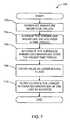
- Example machine readable instructions 500that may be executed to implement the on/off identifier 116 of FIGS. 1-4A , including the example data collector 306 , the example remote control hint collector 302 , the example microphone gain collector 304 , the example signature collector 308 , the example signature characteristic determiner 310 , the example integrated magnitude determiner 312 , the example magnitude standard deviation determiner 314 , the example fuzzy logic engine 316 , and/or the example output database 318 , the example gain evaluator 402 , the example remote control hint evaluator 404 , the example standard deviation evaluator 406 , the example integrated magnitude evaluator 408 , the example input convergence evaluator 410 , the example fuzzy logic contribution analyzer 412 , the example crediting contribution analyzer 414 and/or the creditor 418 are represented by the flowchart shown in FIG.
- the example machine readable instructions 500are executed to determine whether a media presentation device (e.g., the STB 104 and/or the television 106 ) located within a monitored viewing area (e.g., the monitored area 120 ) and monitored via an audience measurement device (e.g., the audience measurement device 108 ) is in an on state or an off state. While the example machine readable instructions 500 are shown to be executed within a back office (e.g., the back office 114 of FIG. 1 ), the instructions may be executed anywhere that the data collected via the audience measurement device 108 may be accessed. For example, the example machine readable instructions 500 may be executed within the audience measurement device 108 . Furthermore, the example machine readable instructions 500 may be executed at periodic or aperiodic intervals, based on an occurrence of a predetermined event (e.g., a full or nearly full memory), etc., or any combination thereof.
- a media presentation devicee.g., the STB 104 and/or the television 106
- the example machine readable instructions 500 of FIG. 5initially cause the data collector 306 of the on/off identifier 116 to extract and/or collect data (e.g., a microphone gain record, a remote control hint record, a signature record, etc.) from the input database 204 containing audience measurement data collected at the monitored area 120 with the audience measurement device 108 (block 502 ).
- the microphone gain collector 304 of the on/off identifier 116then extracts a gain applied to a microphone associated with the audience measurement device 108 from the input database 204 (block 504 ).
- the gain collected from the input database 204may, for example, represent the actual gain applied to the microphone while collecting audio in the metered monitored area 120 or may be additionally processed (e.g., filtered).
- the remote control hint collector 302collects remote control hint(s) corresponding to the remote control commands captured by the audience measurement device 108 corresponding to the remote control 112 operated by a person (e.g., the household member 110 ) (block 506 ).
- the remote control hint collector 302collects the remote control hints from the input database 204 .
- the signature collector 308 of the on/off identifier 116collects a signature from the input database 204 , determines a characteristic of the signature (e.g., the magnitude of the signature) and creates inputs to be analyzed (blocks 508 - 512 ).
- the signature collector 508 of the illustrated examplecollects a signature stored in the input database 204 and extracted from ambient audio recorded by the audience measurement device 108 (block 508 ).
- the signaturecan be extracted from audio obtained from a wired connection to the STB 104 and/or the television 106 .
- the integrated magnitude determiner 312 of the signature characteristic determiner 310integrates the magnitude of the signature over a period of time (e.g., 7.5 seconds) (block 510 ).
- a standard deviation signature characteristic determiner 314determines a value representing the standard deviation of the magnitude for the same or a different period of time (e.g., 15 seconds) (block 512 ).
- the determined at blocks 502 - 512are then analyzed via the example fuzzy logic engine 316 to generate the fuzzy logic values described above (block 514 ).
- the fuzzy logic enginenormalizes (i.e. calculates a correction value) and filters (i.e., applies a filter comprising an extrema engine) to the results of the analysis from block 510 (block 516 ).
- the example on/off identifier 116identifies whether a media presentation device (e.g., such as the television 106 ) is in the on state or the off state during the corresponding periods of time metered with the audience measurement device 108 based on the normalized/filtered final fuzzy logic values (block 518 ).
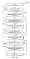
- Example machine readable instructions 600that may be executed to implement the magnitude standard deviation determiner 314 of FIG. 3 and/or used to implement block 512 of FIG. 5 to determine a standard deviation of a magnitude associated with a signature over a specified time period (for brevity hereafter referred to as the standard deviation) are represented by the flowchart shown in FIG. 6 .
- the example machine readable instructionsare executed to calculate the standard deviation for each sample period (e.g., 15 seconds) in the time period during which it is desired to determine the on state and/or off state of the media presentation device. While, the example instructions 600 of FIG.
- the instructionsmay be executed anywhere that the data collected via the audience measurement device 108 may be accessed.
- the example machine readable instructions 600may be executed within the audience measurement device 108 .
- the example machine readable instructions 600may be executed at periodic or aperiodic intervals, based on an occurrence of a predetermined event (e.g., a full or near full memory), etc., or any combination thereof.
- the example machine readable instructions 600 of FIG. 6begin when the magnitude standard deviation determiner 314 determines the magnitude values associated with signature(s) corresponding to a specified time period (e.g., 15 seconds) (block 602 ). Next, the standard deviation determiner 314 calculates a standard deviation for the magnitude values determined in block 602 (block 604 ). Any appropriate method(s) of calculating standard deviations and associated characteristics of standard deviations may be used.
- the standard deviation determiner 314determines the lower bound of a set of standard deviation(s) (block 606 ).
- the standard deviation determiner 314implements a circular buffer to determine a sliding value of standard deviation values.
- the current calculated standard deviationoverwrites the oldest standard deviation in the circular buffer.
- the circular buffermay store, for example, 120 elements storing standard deviation values calculated for a 15-second time period (block 608 ).
- the magnitude standard deviation determiner 314calculates a new lower bound standard deviation value for the elements within the circular buffer (block 608 ).
- any other value associated with a standard deviation(e.g., an upper bound) may alternatively be determined.
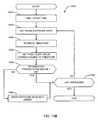
- Example machine readable instructions 700that may be executed to implement the integrated magnitude determiner 312 of FIG. 3 and/or used to implement block 510 of FIG. 5 are represented by the flowchart shown in FIG. 7 .
- the example machine readable instructions 700 of FIG. 7are executed to calculate the integrated magnitude associated with signature(s) corresponding to each sample period (e.g., 7.5 seconds). While the example machine readable instructions 700 are shown to be executed within the example on/off identifier 116 , the instructions may be executed anywhere that data collected via the audience measurement device 108 may be accessed. For example, the example machine readable instructions 700 may be executed within the audience measurement device 108 .
- the example machine readable instructions 600may be executed at periodic or aperiodic intervals, based on an occurrence of a predetermined event (e.g., a full or near full memory), etc., or any combination thereof.
- the example machine readable instructions 700 of FIG. 7begin by causing the integrated magnitude determiner 312 to normalize the magnitude values of the signature(s) taken within the sample time period (e.g., 7.5 seconds) (block 702 ).
- a normalized magnitudeis calculated by the integrated magnitude determiner 312 for each magnitude value associated with the sample period by adding a correction value to each magnitude value.
- the correction valuemay be a constant or a result of an equation based on factors associated with an example implementation. For example, a correction factor may be determined to be the gain of the microphone used to collect the signature at the collection time divided by 5 based on characteristics of the microphone.
- the integrated magnitude determiner 312averages the normalized magnitude data values calculated over the sample time period (e.g., 2 seconds) (block 704 ).
- the integrated magnitude determiner 312then integrates the normalized magnitude values over a sample period (e.g., approximately 7.5 seconds) (block 706 ).
- An example integration calculationis given by the following equation: SUM (M* ⁇ T)/T where M is the average normalized magnitude, ⁇ T is the time between the magnitude data values summed within the time period and T is the time period of the sample.
- the integrated magnitude determinerinserts the result of the integration calculation into a filter (e.g., a lower bound filter) (block 708 ).
- a lower bound filter within the integrated magnitude determiner 312identifies the lowest value of a buffer containing the value to be used as the integrated magnitude of the signature.
- a circular buffer of 12 elementsis sampled, with each element containing an integrated magnitude over the corresponding time period (e.g., 7.5 seconds).
- the integrated magnitude determiner 312selects the lowest value in the buffer to yield an output to represent the integrated magnitude of the signature(s) over, for example, the previous 90 seconds (block 710 ).
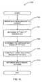
- Example machine readable instructions 800that may be executed to implement the gain evaluator 402 of FIG. 4A and/or used to implement, block 504 of FIG. 5 are represented by the flowchart shown in FIG. 8 .
- the flowchart of FIG. 8also illustrates an example manner of implementing a portion of block 510 of FIG. 5 .
- the example machine readable instructions 800 of FIG. 8are executed to evaluate the gain applied to the microphone of the example audience measurement device 108 to determine a fuzzy contribution value (e.g., a positive or negative value that corresponds to an on state or an off state) and an audio test score value (e.g., a variable that reflects when the analysis corresponds to an on state).
- a fuzzy contribution valuee.g., a positive or negative value that corresponds to an on state or an off state
- an audio test score valuee.g., a variable that reflects when the analysis corresponds to an on state.
- the example machine readable instructions 800are shown to be executed within the example on/off identifier 116 of the back office 114 , the instructions may be executed anywhere that data collected via the audience measurement device 108 may be accessed.
- the example machine readable instructions 800may also be executed within the audience measurement device 108 .
- the example machine readable instructions 800may be executed at periodic or aperiodic intervals, based on an occurrence of a predetermined event (e.g., a full or near full memory), etc., or any combination thereof.
- the example machine readable instructions 800operate on the audio gain data that was collected by the microphone gain collector 302 at block 502 of FIG. 5 .
- the gain evaluator 402then samples the audio gain of the audience measurement device, for example, every 2 seconds (block 802 ).
- the gain evaluator 402analyzes a first sample of the gain to determine whether the gain sample is greater than or equal to a specified gain level (e.g., 52 dB) (block 804 ). If the gain evaluator 402 determines that the sampled gain is greater than or equal to the specified gain level (e.g., 52 dB), the gain evaluator 402 calculates a negative first fuzzy contribution value (block 806 ).
- the gain evaluator 402calculates a positive first fuzzy contribution value (block 808 ).
- the gain evaluator 402further analyzes the first fuzzy contribution value to determine whether the calculated first fuzzy contribution value is less than a specified limit (e.g., a limit of 90) (block 810 ).
- the fuzzy contribution valueis set to the first fuzzy contribution value (block 812 ).
- the gain evaluator 402sets the fuzzy contribution value to a maximum limit (block 814 ).
- the positive first fuzzy contribution valueis limited by the gain evaluator 402 in this manner to reduce the influence of a gain corresponding to audio inputs not associated with an audio output signal from a media device.
- the audio gainmay be low and yield a positive contribution value due to the example household members 110 talking within the monitored area 120 even if the monitored media device is off.
- the example machine readable instructions 800operate to bias first fuzzy contribution values indicative of an off state to have a greater contribution than first fuzzy contribution values indicative of an on state
- Example machine readable instructions 900that may be executed to implement the remote control hint evaluator 404 of FIG. 4A and/or used to implement block 506 of FIG. 5 are represented by the flowchart shown in FIG. 9 .
- the example machine readable instructions 900are executed to evaluate remote control hints corresponding to events generated from the remote control 112 to determine whether a display is in an on state or an off state.
- the example machine readable instructions 900are used to determine a fuzzy contribution value (e.g., a positive or negative value that corresponds to an on state or an off state) and an audio test score value (e.g., a variable that reflects when the analysis corresponds to an on state).
- a fuzzy contribution valuee.g., a positive or negative value that corresponds to an on state or an off state
- an audio test score valuee.g., a variable that reflects when the analysis corresponds to an on state.
- the example machine readable instructions 900may be executed within the example on/off identifier 116 of the back office 115 , the instructions may be executed anywhere that data collected via the audience measurement device 108 may be accessed.
- the example machine readable instructions 900may be executed within the audience measurement device 108 .
- the example machine readable instructions 900may be executed at periodic or aperiodic intervals, based on an occurrence of a predetermined event (e.g., a full or near full memory), etc., or any combination thereof.
- the example machine readable instructions 900operate within the example remote control hint evaluator 404 upon a series of remote control hints (e.g., a series of commands entered via the remote control device 112 ) captured within a specified time period (e.g., thirty minutes) and are sampled around specified time intervals.
- the hintsmay comprise a series of hints fifteen minutes before and after the current sample time and taken at 2-second intervals.
- the instructions of FIG. 9begin when the hints sampled within a time frame at issue are compared by the remote control hint evaluator to determine whether two hints occur within a specified time (e.g., 15 minutes) of each other (block 704 ).
- the remote control hint evaluator 404determines that the hints are not helpful in determining the on state or the off state of the media presentation device and, therefore, the second fuzzy contribution value is assigned a value of zero (block 906 ).
- the remote control hint evaluator 404compares the hints to determine whether the hints occur within the specified time of the current sample times being examined (block 908 ). For example, if the remote control hint evaluator determines that (1) two hints occur within fifteen minutes of each other (block 904 ), (2) the first hint is within 15 minutes of the current sample time, but (3) the second hint occurs 18 minutes before the current time (block 908 ), then control advances to block 906 and the hints do not contribute to the fuzzy logic analysis. However, if the two hints occur within fifteen minutes of the current time (block 908 ), then control advances to block 910 . The hints are assigned a second fuzzy contribution value of +3 (block 910 ).
- Example machine readable instructions 1000that may be executed to implement the standard deviation evaluator 406 of FIG. 4A and/or used to implement, block 514 of FIG. 5 are represented by the flowchart shown in FIG. 10 .
- the example machine readable instructions 1000are used to determine the third fuzzy contribution value (e.g., a positive or negative value that corresponds to an on state or an off state). While, the example machine readable instructions 1000 may be executed within the example on/off identifier 116 , the instructions may be implemented anywhere that data collected via the audience measurement device 108 may be accessed. For example, the example machine readable instructions 1000 may also be executed within the audience measurement device 108 . Furthermore, the example machine readable instructions 1000 may be executed at periodic or aperiodic intervals, based on an occurrence of a predetermined event (e.g., a full or near full memory), etc., or any combination thereof.
- a predetermined evente.g., a full or near full memory
- the example machine readable instructions 1000evaluate a lower bound standard deviation (LBSD) output from the magnitude standard deviation determiner 314 to determine the third fuzzy contribution value to be assigned to the LBSD output (block 1004 ).
- the standard deviation determinercalculates the third fuzzy contribution value by evaluating a function associated with the LBSD, and example being an example function may subtract a constant from the LBSD, where the constant value and/or function utilized in the calculation is implementation specific and varies depending on the application. For example, experimental results have shown that LBSD values less than 10 corresponded to an off state of the television 106 and the television on state corresponded to LBSD values within the range of 10 to 20. For example, an example constant of 15, representing a threshold to determine an on state indication.
- third fuzzy contributionLBSD ⁇ 15.
- the example machine readable instructions 1000operate to bias third fuzzy contribution values indicative of an off state to have a greater contribution than third fuzzy contribution values indicative of an on state
- Example machine readable instructions 1100that may be executed to implement the integrated magnitude evaluator 408 of FIG. 4A and/or used to implement block 510 of FIG. 5 are represented by the flowchart shown in FIG. 11 .
- the example machine readable instructions 1100evaluate the integrated magnitude determined by the example integrated magnitude determiner 312 to determine whether a monitored device is in an on state or an off state. Further, the example machine readable instructions 1100 are used to determine a fuzzy contribution value (e.g., a positive or negative value that corresponds to an on state or an off state) While the example machine readable instructions 1100 are shown to be executed within the example on/off identifier 116 , the instructions may be executed anywhere that data collected via the audience measurement device 108 may be accessed.
- a fuzzy contribution valuee.g., a positive or negative value that corresponds to an on state or an off state
- the example machine readable instructions 1100may be executed within the audience measurement device 108 . Furthermore, the example machine readable instructions 1100 may be executed at periodic or aperiodic intervals, based on an occurrence of a predetermined event (e.g., a full or near full memory), etc., or any combination thereof.
- a predetermined evente.g., a full or near full memory
- the example machine readable instructions 1100 of FIG. 11begin by causing the integrated magnitude evaluator 408 to assign a value to the fourth fuzzy contribution value by evaluating an equation corresponding to the integrated magnitude value, for example, subtracting a constant value from the integrated magnitude value (e.g., an integrated magnitude ⁇ 55) (block 1102 ).
- the constant value and/or function utilized in the calculation of the integrated magnitude valueis implementation specific and varies depending on the application.
- the example constantrepresents a threshold value of the integrated magnitude corresponding with the lowest end of a range of experimentally determined values that indicate an on state of a media presentation device. For example, experimental results from an example implementation depicted in FIG.
- the integrated magnitude evaluator 408then examines the fourth fuzzy contribution value to determine whether it has positive or negative value (block 1104 ). If the fourth fuzzy contribution value is a negative number (block 1104 ), then the integrated magnitude evaluator 408 multiplies the fourth fuzzy contribution value by two (block 1106 ).
- the fourth integrated magnitude evaluator 408does not change the fuzzy contribution value calculated at block 1102 and the instructions of FIG. 11 terminate. In this manner, the example machine readable instructions 1100 operate to bias fourth fuzzy contribution values indicative of an off state to have a greater contribution than fourth fuzzy contribution values indicative of an on state.
- Example machine readable instructions 1200 and 1250 that may be executed to implement the example input convergence evaluator 410 of FIG. 4A and/or used to implement block 514 of FIG. 5are represented by the flowcharts shown in FIGS. 12A-12B .
- the example machine readable instructions 1200 of FIG. 12Aevaluate the number of fuzzy inputs (e.g., fuzzy inputs corresponding to a gain applied to a microphone, remote control hints, an integrated magnitude of a signature over a period of time, a standard deviation value of a signature over a period of time, etc.) having a positive fuzzy contribution value to calculate an audio test score value.
- fuzzy inputse.g., fuzzy inputs corresponding to a gain applied to a microphone, remote control hints, an integrated magnitude of a signature over a period of time, a standard deviation value of a signature over a period of time, etc.
- a fifth fuzzy contribution value(e.g., a positive or negative value that corresponds to an on state or an off state) based on the audio test score value.
- the example machine readable instructions 1200 and 1250may be executed within the example on/off identifier 116 , the instructions may be executed anywhere that data collected via the audience measurement device 108 may be accessed.
- the example machine readable instructions 1200 and 1250may also be executed within the audience measurement device 108 .
- the example machine readable instructions 1200 and 1250may be executed at periodic or aperiodic intervals, based on an occurrence of a predetermined event (e.g., a full or near full memory), etc., or any combination thereof.
- the example machine readable instructions 1200begin when the input convergence evaluator 410 determines if the first fuzzy contribution value output by the gain evaluator 402 is a value greater than zero (block 1202 ). If the first fuzzy contribution value is a positive number (block 1202 ), the output of the gain evaluator 402 indicates that the monitored media presentation device is in the on state and the audio test score value is incremented by one (block 1204 ). If the first fuzzy contribution value is determined to be a negative number (block 1202 ), the output of the gain evaluator 402 indicates that the monitored media presentation device is in the off state and the audio test score value is not incremented by the input convergence evaluator 410 .
- the input convergence evaluator 410evaluates, irrespective of whether control reached block 1206 via block 1204 or directly from block 1202 , the second fuzzy contribution value output by the remote control hint evaluator 404 to determine whether the second fuzzy contribution value is greater than zero (block 1206 ). If the second fuzzy contribution value is a positive number (block 1206 ), the output of the remote control hint evaluator 404 indicates that the monitored media presentation device is in the on state and an audio test score value is incremented by one (block 1208 ). Control then advances to block 1210 .
- the output of the remote control hint evaluator 404indicates that the monitored media presentation device is in the off state and the audio test score value is not incremented by the input convergence evaluator 410 . Control then advances to block 1210 .
- the input convergence evaluator 410evaluates the third fuzzy contribution value output by the standard deviation evaluator 406 to determine whether the third fuzzy contribution value is greater than zero (block 1210 ). If the third fuzzy contribution value is a positive number (block 1210 ), the output of standard deviation evaluator 406 indicates that the monitored media device is in the on state and an audio test score value is incremented by one (block 1212 ). Control then advances to block 1214 .
- the output of the standard deviation evaluator 406indicates that the monitored media device is in the off state and the audio test score value is not incremented by the input convergence evaluator 410 . Control then advances to block 1214 .
- the input convergence evaluator 410evaluates the fourth fuzzy contribution value output by the integrated magnitude evaluator 408 to determine whether the fourth fuzzy contribution value is greater than zero (block 1214 ). If the fourth fuzzy contribution value is a positive number (block 1214 ), the output of integrated magnitude evaluator 408 indicates that the monitored media device is in the on state and an audio test score value is incremented by one (block 1216 ). Control then advances to block 1252 of FIG. 12B .
- the output of the integrated magnitude evaluator 408indicates that the monitored media device is in the off state and the audio test score value is not incremented by the input convergence evaluator. Control then advances to block 1252 of FIG. 12B .
- the input convergence evaluator 410evaluates the audio test score to assign a value to a fifth fuzzy contribution.
- the input convergence evaluator 410evaluates the audio test score to determine if the value is zero (block 1252 ).
- the audio test scorewill be zero if no input evaluators (e.g., the gain evaluator 402 , the remote control hint evaluator 404 , the standard deviation evaluator 406 and the integrated magnitude evaluator 408 ) indicated the on state.
- the fifth fuzzy contribution value for the input convergence evaluator 410is assigned a value of ⁇ 40 by the input convergence evaluator 410 (block 1254 ).
- the instructions of FIG. 12Bthen terminate. If the audio test score is not zero (block 1252 ), the input convergence evaluator 410 evaluates the audio test score to determine if the audio test score is one (block 1256 ), the audio test score equals one if only one of the input evaluators indicates the media presentation device is in the on state (block 1256 ). If the audio test score has a value of one (block 1256 ), then the input convergence evaluator 410 assigns a value of ⁇ 30 to the fifth fuzzy contribution value (block 1258 ). The instructions of FIG. 12B then terminate.
- the input convergence evaluator 410evaluates the audio test score to determine if the value is two (block 1260 ). The audio test score equals two if only two of the input evaluators indicate the media presentation device is in the on state (block 1260 ). If the audio test score has a value of two, then the fifth fuzzy contribution value for the input convergence evaluator 410 is assigned a value of ⁇ 10 (block 1262 ). The instructions of FIG. 12B then terminate.
- the input convergence evaluator 410evaluates the audio test score to determine if the value is three (block 1264 ). The audio test score equals three if only three of the input evaluators indicate the media presentation device is in the on state (block 1264 ). If the audio test score has a value of three, then the fifth fuzzy contribution value for the input convergence evaluator 410 is assigned a value of +10 (block 1266 ). The instructions of FIG. 12B then terminate.
- the input convergence evaluator 410evaluates the audio test score to determine if the value is four (block 1268 ). The audio test score equals four if four of the input evaluators indicate the media presentation device is in the on state (block 1268 ). If the audio test score has a value of four, then the fifth fuzzy contribution value for the input convergence evaluator 410 is assigned a value of +30 (block 1270 ). The instructions of FIG. 12B then terminate. However, if the audio test score is not four (block 1268 ), the audio test score has a value outside the expected range (e.g., 0 through 4) and, therefore the audio test score is reset to 0 (block 1272 ). The instructions of FIG. 12B then terminate.
- the fifth fuzzy contributionis a value assigned a value of ⁇ 40, ⁇ 30, ⁇ 10, 10 or 30 depending on the value of the audio test score.
- assignment valuesare illustrative examples and are not meant to be limiting. For example, other assignment values may be used depending on the range of possible values of the audio test score, different biases desired to be introduced to the fifth fuzzy contribution value, etc.
- Example machine readable instructions 1300that may be executed to implement the fuzzy contribution analyzer 412 of FIG. 4A and/or used to implement the processing at block 516 of FIG. 5 are represented by the flowchart shown in FIG. 13 .
- the example machine readable instructions 1300are executed to analyze the fuzzy contributions provided by the above-mentioned evaluators (e.g., the gain evaluator 402 , the remote control hint evaluator 404 , the standard deviation evaluator 406 , integrated magnitude evaluator 408 and the input convergence evaluator 410 ). Further, the example machine readable instructions 1300 are used to determine a sum (e.g., an intermediate fuzzy score) of all the fuzzy contribution values from the above-mentioned input evaluators.
- a sume.g., an intermediate fuzzy score
- example machine readable instructions 1300may be executed within an on/off identifier (e.g., the example on/off identifier 116 ), a fuzzy logic engine (e.g., the fuzzy logic engine 316 ) and/or within an analyzer (e.g., the fuzzy contribution analyzer 412 ), the instructions may also be executed anywhere data collected via the audience measurement device 108 may be accessed.
- the example machine readable instructions 1300may also be implemented within the audience measurement device 108 .
- the example machine readable instructions 1300may be executed at periodic or aperiodic intervals, based on an occurrence of a predetermined event (e.g., a full or near full memory), etc., or any combination thereof.
- the example machine readable instructions 1300begin, for example, when the fuzzy contribution analyzer 412 sums the fuzzy contribution values provided by each of the example evaluators (e.g., the gain evaluator, the remote control hint evaluator 404 , the standard deviation evaluator 406 and the integrated magnitude evaluator 408 ) at the end of each processing cycle (e.g., every engine cycle of two seconds) of the fuzzy logic engine 316 and stores the sum as an intermediate fuzzy score (block 1302 ).
- the fuzzy contribution analyzer 412sums the fuzzy contribution values provided by each of the example evaluators (e.g., the gain evaluator, the remote control hint evaluator 404 , the standard deviation evaluator 406 and the integrated magnitude evaluator 408 ) at the end of each processing cycle (e.g., every engine cycle of two seconds) of the fuzzy logic engine 316 and stores the sum as an intermediate fuzzy score (block 1302 ).
- the fuzzy contribution analyzer 412places the intermediate fuzzy score in a first-in, first-out (FIFO) circular buffer of, for example, 30 elements which represents data evaluated over a specified time period (e.g., 30 engine cycles), where each element corresponds to one engine cycle (e.g., two seconds) (block 1304 ).
- the fuzzy contribution analyzer 412determines via a timer or counter whether a first specified time period has passed (e.g., 10-15 seconds) (block 1306 ). If the first time period has not passed (block 1306 ), the fuzzy contribution analyzer 412 determines the intermediate fuzzy score for the next engine cycle (block 1302 ).
- the fuzzy contribution analyzer 412examines the entries in the example circular buffer using any outlier removal method (e.g., the example method 1500 of FIG. 15 ) to remove values that lie outside a specified range for valid data (e.g., between a 25 th percentile and a 75 th percentile (block 1308 ). The fuzzy contribution analyzer 412 then averages the remaining values in the circular buffer and stores the average as the final fuzzy score for the first time period (block 1310 ).
- any outlier removal methode.g., the example method 1500 of FIG. 15
- the fuzzy contribution analyzer 412then averages the remaining values in the circular buffer and stores the average as the final fuzzy score for the first time period (block 1310 ).
- the fuzzy contribution analyzer 412determines whether data corresponding to a second specified time period has been collected (e.g., data corresponding to a twenty-four hour period) (block 1312 ). If not, control returns to block 1302 . If, however, the specified time period has elapsed (block 1312 ), the fuzzy contribution analyzer 412 examines the final fuzzy score values collected during the second specified time period and determines the difference between the minimum and maximum values for the second specified time period (block 1314 ). The difference between the minimum and maximum final fuzzy score values for the specified time period are examined to determine whether the difference is greater than a maximum threshold value (e.g., a value of 150) (block 1316 ).
- a maximum threshold valuee.g., a value of 150
- the fuzzy contribution analyzer 412determines a normalization factor (block 1318 ).
- the fuzzy contribution analyzer 412adds the normalization factor to each final fuzzy score value within the time period (block 1320 ).
- the fuzzy contribution analyzer 412filters the normalized fuzzy score values of the time period (e.g., using an example extrema filter) (block 1322 ).
- An example extrema filtermay be implemented within the fuzzy contribution analyzer by determining a maximum final fuzzy score value for a specified number of entries (e.g., thirty entries) and then setting the value for each of the examined entries to the determined maximum value.
- Example machine readable instructions 1400 and 1450 that may be executed to implement the crediting contribution analyzer 414 of FIG. 4A and/or used to implement block 518 of FIG. 5are represented by the flowcharts shown in FIGS. 14A and 14B .
- the crediting contribution analyzer 414analyzes the final fuzzy score values determined by the fuzzy contribution analyzer 412 to determine whether a media device was in an on state or an off state within a specified time period and, thus, to determine whether media detected during the time period should be credited as media exposure.
- the example machine readable instructions 1400may be executed within the example on/off identifier 116 , the instructions may be executed anywhere data collected via the audience measurement device 108 may be accessed.
- the example machine readable instructions 1400may also be implemented within the audience measurement device 108 .
- the example machine readable instructions 1400may be executed at periodic or aperiodic intervals, based on an occurrence of a predetermined event (e.g., a full or near full memory), etc., or any combination thereof.
- the example machine readable instructions 1400begin when the crediting contribution analyzer 414 extracts final fuzzy score values corresponding to particular time periods (e.g., 10 or 15 second intervals beginning at a certain specified time) (block 1402 ).
- the crediting contribution analyzer 414then analyzes signature matching data and/or crediting information corresponding to the same example time period to determine whether a match (e.g., a signature match and/or crediting match) was found within the specified time period (block 1404 ). If the crediting contribution analyzer 414 determines a signature match occurred during the examined time period, each final fuzzy score within the examined time period is adjusted by a specified value (e.g., adding a constant value of +125) (block 1406 ).
- a specified valuee.g., adding a constant value of +125
- each final fuzzy score e within the time periodis adjusted by a second specified value (e.g., a constant value of ⁇ 125) (block 1408 ).
- the first and second specified values used to adjust the final fuzzy scoremay be constant values, as in the illustrated example, and/or determined based on an equation corresponding to the match.
- the constant value and/or equation utilized by the crediting contribution analyzer 414 to increment the final fuzzy scoreis implementation specific and varies depending on the application.
- the crediting contribution analyzer 414determines whether all final fuzzy scores have been evaluated (block 1410 ). If all of the final fuzzy scores have not been evaluated, the crediting contribution analyzer 414 extracts the final fuzzy scores for the next time period to be examined (block 1402 ). If the crediting contribution analyzer 414 has examined and adjusted all of the final fuzzy scores for the current time period, the adjusted final fuzzy score values are processed by an extrema filter to determine time intervals during which a media presentation device may have been in an on state or an off state (block 1412 ). For brevity, an interested reader is referred to the example extrema filter discussed above in conjunction with FIG. 13 .
- the example machine readable instructions 1450begin when the creditor 416 extracts a timestamp associated with a final fuzzy score value associated with a start time of the specified time period (block 1452 ).
- the creditor 416collects media exposure information, including both the signature and any crediting match, found for the specified time period within a database in the back office 116 (block 1454 ).
- the creditor 418then reviews the timestamp associated with the collected media exposure (block 1456 ).
- the creditor 416gathers the final fuzzy score value corresponding to the timestamp associated with the crediting information (block 1458 ).
- the timestamps associated with the media exposure and the timestamp associated with the final fuzzy valueare then analyzed to determine whether the information presentation device was on at the time specified by the associated timestamps (block 1460 ). If the creditor 416 determines that the media presentation device was on (block 1460 ), then the media exposure information is not modified and processing continues until the last of the media exposure data corresponding to the specified time period has been examined (block 1468 ). Conversely, if the media presentation device was determined to be off by the creditor 416 (block 1460 ), then the media exposure information associated to the timestamp is marked to indicate that no valid crediting match occurred during the time (block 1466 ).
- the media exposure informationis examined to determine whether the last of the media exposure data had been examined (block 1468 ). If the creditor 416 determines that no more media exposure information remains, the instructions of FIG. 14B terminate. Conversely, if the creditor 418 determines that more media exposure information remains (block 1468 ), then the instructions return to gather the next media exposure information (block 1454 ).
- Example machine readable instructions 1500that may be executed to identify data points falling outside a specified range of values within an examined time period (e.g., outliers) are represented by the flowchart shown in FIG. 15 .
- the example instructions of FIG. 15may be used to implement, for example, the fuzzy contribution analyzer 412 and/or block 1308 of FIG. 13 .
- the example machine readable instructions 1500determine a data point that lies outside a specified range of values of a data set (e.g., outside the range between a first quartile and a third quartile). While, the example machine readable instructions 1500 of FIG. 15 may be executed by the example on/off identifier 116 , the instructions may be executed anywhere that data collected via the audience measurement device 108 may be accessed.
- the example machine readable instructions 1500may also be implemented within the audience measurement device 108 . Furthermore, the example machine readable instructions 1500 may be executed at periodic or aperiodic intervals, based on an occurrence of a predetermined event (e.g., a full or near full memory), etc., or any combination thereof.
- a predetermined evente.g., a full or near full memory
- the example machine readable instructions 1500begin by ordering the data within the set to be examined (e.g., the data stored within the buffer as explained in conjunction with the instructions 1300 described above) from the smallest to largest value (e.g., an example of an ordered data set comprising nine entries is: 35, 47, 48, 50, 51, 53, 54, 70, 75) (block 1502 ).
- the range containing valid datais determined by calculating indexes associated with the start and end of the valid data range (e.g., calculating an index associated with the 25 th percentile or first quartile and an index associated with the 75 th percentile or third quartile of the examined values) (block 1504 ).
- a percentile valueis determined by multiplying the sample size (e.g., the number of values to be examined) by the percentile to be calculated (e.g., the 25 th or Q1 value and the 75 th percentile or Q3 value) (block 1504 ).
- the fuzzy contribution analyzer 412determines the percentiles (e.g., the 25 th and 75 th percentiles corresponding to the first quartile and third quartiles, respectively)
- a percentile calculatedis not an integer index
- an upper fence value and a lower fence valueare determined for use in determining outliers (block 1508 ).
- a value within a sampled data setis termed an outlier if it lies outside a determined, so-called fence.
- the lower fence valueis determined by Q1 ⁇ 1.5*(Q3 ⁇ Q1) and the upper fence value may be calculated by Q3+1.5*(Q3 ⁇ Q1) (block 1508 ).
- the outliersare identified as the values above the upper fence and below the lower fence and eliminated (block 1510 ). Any value of the example data set that falls outside the range of 39 through 63, is determined to be an outlier (e.g., in the example data set, the values 35, 70 and 75 are outliers).
- FIG. 16is a graph representing example gain levels 1602 of a microphone associated with an audience measurement device 108 of FIG. 1 versus time 1604 .
- the gain levels 1602may be obtained from the data file 204 of FIG. 2 ) by the gain collector 304 and processed by the gain evaluator 402 as explained above.
- Periods of time, such as the example time period 1606are further labeled to indicate the actual operating state (e.g., an on state or an off state) of a media presentation device (e.g., the STB 104 and/or the television 106 ) during the respective period of time 1606 measurement was performed by the audience measurement device 108 .
- a gain threshold 1608(e.g., 52 dB) is defined as the threshold used to determine whether the captured gain (e.g., the gain level 1610 ) generates a positive fuzzy contribution value (e.g., corresponding to a likely on state) or a negative fuzzy contribution value 1612 (e.g., corresponding to a likely off state).
- a gain level below the thresholdcorrespondingly yields a positive fuzzy value and a gain level below the threshold yields a negative fuzzy value.
- a gain level 1614 having a value above the threshold 1608(e.g., 55 dB>52 dB) may occur even when the monitored device is in an on state.
- This conditionmay correspond to a low volume audio output or a mute state of the media presentation device.
- a gain level 1610 associated with an off state of the monitored devicemay have a value below the threshold 1608 as a result of persons (e.g., the household members 110 ) speaking within the metering area 120 .
- FIG. 17depicts example standard deviation data calculated by the magnitude standard deviation determiner 314 and graphed versus time. An examination of these experimental results reveals that standard deviations value between zero and ten (the standard deviation value 1702 ) are associated with a television off condition. Further, the experimental results also revealed that an on state correlated with a standard deviation value within the range of standard deviation values 1704 between 10 and 20. Also, a very high standard deviation, for example the standard deviation value 1706 , also was associated with an off condition and may, thus, also be included in the calculation of a fuzzy contribution value within a the standard deviation evaluator 406 of FIG. 4A .
- FIG. 18is a graph depicting example magnitude values that may be generated by the integrated magnitude determiner 312 .
- the sample outputscorrespond to the integrated magnitude of a signature associated with an audio signal captured by a microphone of the audience measurement device 108 .
- the integrated magnitude valueonly generates a fuzzy contribution value when the integrated magnitude value is determined to be negative (e.g., the data point 1802 ) because values above zero may be associated with either an on state or an off state.
- a negative magnitude valuemay be due to, for example, a change in gain of the audio signal used to create the signature or a change in, or occurring during, a normalization process for the signature.
- FIGS. 19A and 19Bare figures representing example intermediate fuzzy score values that may be calculated by the fuzzy logic engine 316 .
- FIG. 19Cis a figure representing example final fuzzy score values that may be calculated by the fuzzy logic engine 316 .
- FIGS. 19A and Brepresent an example intermediate fuzzy score value that has been calculated in the fuzzy contribution analyzer 412 as discussed in conjunction with FIG. 4A and with FIG. 13 .
- FIG. 19Aalso represents an intermediate fuzzy score record that may be determined prior to the normalization procedure discussed above along with FIG. 13 .
- an intermediate fuzzy value(e.g., the data point 1902 ) indicating an on state may have a value of +10
- another intermediate fuzzy value(e.g., the data point 1904 ) that represents an off state may have a value of ⁇ 200.
- the intermediate fuzzy values included in the fuzzy score recordare preferably centered on zero, so that any positive value is associated with an on state and a negative value is associated with an off state.
- FIG. 19Brepresents the example intermediate fuzzy score value of FIG. 19A after application of a normalization method to the data to center the intermediate fuzzy values resenting an on state and off state around zero (e.g., the normalization procedure described above in conjunction with FIG. 13 ).
- FIG. 19Crepresents example final fuzzy score values corresponding to the intermediate fuzzy values shown in FIG. 19A and normalized as shown in FIG. 19B .
- the final fuzzy scores shown in FIG. 19Creflect adjustment by signature matching contribution determined from processing in the crediting contribution analyzer 414 .
- the crediting and/or signature match contributionmakes a significant impact on the output of the fuzzy logic engine 316 .
- the crediting and/or signature match contributioncan enhance the fuzzy score to differentiate between fuzzy scores representing whether a media presentation device is in an on state or an off state.
- this graphrepresents an example final fuzzy score output from the fuzzy logic engine 316 that can be used to determine time periods where a media presentation device (e.g., the example television 106 ) was in an on state or in an off state and is shown by the signal 2002 .
- the fuzzy logic engine 316is configured to output a positive value to represent when a media presentation device is in an on state and a negative value to represent when a media presentation device is in an off state.
- the actual operating state of a media presentation device during a monitored time periodcan be compared with the example output signal 2002 by referring to the actual operating states 2004 .
- the range between the representations of on state and off state valueswas extended to allow the fuzzy score to experience variations without affecting the overall score, as seen in areas 2006 and 2008 .
- the range extensionwas implemented, for example, by utilizing the input convergence evaluator 410 discussed above in conjunction with FIG. 4A to determine a fifth fuzzy contribution value representative of the number of input evaluators (e.g., the gain evaluator 402 , the remote control hint evaluator 404 , the standard deviation evaluator 406 , and the integrated magnitude evaluator 408 ) that indicated an on state (i.e. had a positive fuzzy contribution score).
- the rangewas extended by utilizing an adjustment value implemented as a step input based on a signature matching contribution factor (e.g., the adjustment of the crediting contribution analyzer 414 ).
- FIG. 21is a schematic diagram of an example processor platform 2100 that may be used and/or programmed to execute any or all of the example machine readable instructions of FIGS. 5-15 to implement the on/off identifier 116 , the remote control hint collector 302 , the microphone gain collector 304 , the data collector 306 , the signature collector 308 , the signature characteristic determiner 310 , the integrated magnitude determiner 312 , the magnitude standard deviation determiner 314 , the fuzzy logic engine 316 , the output database 318 , the gain evaluator 402 , the remote control hint evaluator 404 , the standard deviation evaluator 406 , the integrated magnitude evaluator 408 , the input convergence evaluator 410 , the fuzzy contribution analyzer 412 , crediting contribution analyzer 414 , and/or the creditor 418 of FIGS.
- the processor platform 2100can be implemented by one or more general-purpose processors, microcontrollers, etc.
- the processor platform 2100 of the example of FIG. 21includes at least one general-purpose programmable processor 2102 .
- the processor 2102executes coded instructions 2104 and/or 2106 present in main memory of the processor 2102 (e.g., within a RAM 2108 and/or a ROM 2110 ).
- the processor 2102may be any type of processing unit, such as a processor or a microcontroller.
- the processor 2102may execute, among other things, the example methods and apparatus described herein.
- the processor 2102is in communication with the main memory (including a RAM 2108 and/or a ROM 2110 ) via a bus 2112 .
- the RAM 2108may be implemented by dynamic random-access memory (DRAM), synchronous dynamic random-access memory (SDRAM), and/or any other type of RAM device, and the ROM 2110 may be implemented by flash memory and/or any other desired type of memory device.
- a memory controller 2114may control access to the memory 2108 and the memory 2110 .
- the main memorye.g., RAM 2108 and/or ROM 2110
- the processor platform 2102also includes an interface circuit 2116 .
- the interface circuit 2116may be implemented by any type of interface standard, such as an external memory interface, serial port, general purpose input/output, etc.
- One or more input devices 2118 and one or more output devices 2120are connected to the interface circuit 2116 .
Landscapes
- Engineering & Computer Science (AREA)
- Theoretical Computer Science (AREA)
- General Physics & Mathematics (AREA)
- Physics & Mathematics (AREA)
- General Engineering & Computer Science (AREA)
- Software Systems (AREA)
- Signal Processing (AREA)
- Automation & Control Theory (AREA)
- Pure & Applied Mathematics (AREA)
- Mathematical Optimization (AREA)
- Mathematical Analysis (AREA)
- Fuzzy Systems (AREA)
- Computational Mathematics (AREA)
- Artificial Intelligence (AREA)
- Computational Linguistics (AREA)
- Data Mining & Analysis (AREA)
- Evolutionary Computation (AREA)
- Computing Systems (AREA)
- Mathematical Physics (AREA)
- Testing, Inspecting, Measuring Of Stereoscopic Televisions And Televisions (AREA)
Abstract
Description
Claims (29)
Priority Applications (5)
| Application Number | Priority Date | Filing Date | Title |
|---|---|---|---|
| US12/242,337US8180712B2 (en) | 2008-09-30 | 2008-09-30 | Methods and apparatus for determining whether a media presentation device is in an on state or an off state |
| US13/444,571US9312973B2 (en) | 2008-09-30 | 2012-04-11 | Methods and apparatus for determining whether a media presentation device is in an on state or an off state using fuzzy scores and signature matches |
| US15/082,380US10528881B2 (en) | 2008-09-30 | 2016-03-28 | Methods and apparatus for determining whether a media presentation device is in an on state or an off state |
| US16/734,067US11055621B2 (en) | 2008-09-30 | 2020-01-03 | Methods and apparatus for determining whether a media presentation device is in an on state or an off state |
| US17/365,834US20210326733A1 (en) | 2008-09-30 | 2021-07-01 | Methods and apparatus for determining whether a media presentation device is in an on state or an off state |
Applications Claiming Priority (1)
| Application Number | Priority Date | Filing Date | Title |
|---|---|---|---|
| US12/242,337US8180712B2 (en) | 2008-09-30 | 2008-09-30 | Methods and apparatus for determining whether a media presentation device is in an on state or an off state |
Related Child Applications (1)
| Application Number | Title | Priority Date | Filing Date |
|---|---|---|---|
| US13/444,571ContinuationUS9312973B2 (en) | 2008-09-30 | 2012-04-11 | Methods and apparatus for determining whether a media presentation device is in an on state or an off state using fuzzy scores and signature matches |
Publications (2)
| Publication Number | Publication Date |
|---|---|
| US20100083299A1 US20100083299A1 (en) | 2010-04-01 |
| US8180712B2true US8180712B2 (en) | 2012-05-15 |
Family
ID=42059127
Family Applications (5)
| Application Number | Title | Priority Date | Filing Date |
|---|---|---|---|
| US12/242,337Active2030-09-23US8180712B2 (en) | 2008-09-30 | 2008-09-30 | Methods and apparatus for determining whether a media presentation device is in an on state or an off state |
| US13/444,571Active2031-07-30US9312973B2 (en) | 2008-09-30 | 2012-04-11 | Methods and apparatus for determining whether a media presentation device is in an on state or an off state using fuzzy scores and signature matches |
| US15/082,380Active2031-04-30US10528881B2 (en) | 2008-09-30 | 2016-03-28 | Methods and apparatus for determining whether a media presentation device is in an on state or an off state |
| US16/734,067Expired - Fee RelatedUS11055621B2 (en) | 2008-09-30 | 2020-01-03 | Methods and apparatus for determining whether a media presentation device is in an on state or an off state |
| US17/365,834PendingUS20210326733A1 (en) | 2008-09-30 | 2021-07-01 | Methods and apparatus for determining whether a media presentation device is in an on state or an off state |
Family Applications After (4)
| Application Number | Title | Priority Date | Filing Date |
|---|---|---|---|
| US13/444,571Active2031-07-30US9312973B2 (en) | 2008-09-30 | 2012-04-11 | Methods and apparatus for determining whether a media presentation device is in an on state or an off state using fuzzy scores and signature matches |
| US15/082,380Active2031-04-30US10528881B2 (en) | 2008-09-30 | 2016-03-28 | Methods and apparatus for determining whether a media presentation device is in an on state or an off state |
| US16/734,067Expired - Fee RelatedUS11055621B2 (en) | 2008-09-30 | 2020-01-03 | Methods and apparatus for determining whether a media presentation device is in an on state or an off state |
| US17/365,834PendingUS20210326733A1 (en) | 2008-09-30 | 2021-07-01 | Methods and apparatus for determining whether a media presentation device is in an on state or an off state |
Country Status (1)
| Country | Link |
|---|---|
| US (5) | US8180712B2 (en) |
Cited By (12)
| Publication number | Priority date | Publication date | Assignee | Title |
|---|---|---|---|---|
| US20100114527A1 (en)* | 2008-10-31 | 2010-05-06 | Morris Lee | Probabilistic methods and apparatus to determine the state of a media device |
| US20130241730A1 (en)* | 2012-03-15 | 2013-09-19 | Behavioral Recognition Systems, Inc. | Alert volume normalization in a video surveillance system |
| US20160043818A1 (en)* | 2014-08-06 | 2016-02-11 | The Nielsen Company (Us) Llc | Methods and apparatus to detect a state of media presentation devices |
| US9473795B2 (en) | 2011-12-19 | 2016-10-18 | The Nielsen Company (Us), Llc | Methods and apparatus for crediting a media presentation device |
| US20170093854A1 (en)* | 2015-09-25 | 2017-03-30 | The Nielsen Company (Us), Llc | Methods and apparatus to identify media using hybrid hash keys |
| US9692535B2 (en) | 2012-02-20 | 2017-06-27 | The Nielsen Company (Us), Llc | Methods and apparatus for automatic TV on/off detection |
| US9924224B2 (en) | 2015-04-03 | 2018-03-20 | The Nielsen Company (Us), Llc | Methods and apparatus to determine a state of a media presentation device |
| US9961342B2 (en) | 2005-08-16 | 2018-05-01 | The Nielsen Company (Us), Llc | Display device on/off detection methods and apparatus |
| US10225730B2 (en)* | 2016-06-24 | 2019-03-05 | The Nielsen Company (Us), Llc | Methods and apparatus to perform audio sensor selection in an audience measurement device |
| US10528881B2 (en) | 2008-09-30 | 2020-01-07 | The Nielsen Company (Us), Llc | Methods and apparatus for determining whether a media presentation device is in an on state or an off state |
| US12088875B2 (en) | 2014-04-07 | 2024-09-10 | The Nielsen Company (Us), Llc | Signature retrieval and matching for media monitoring |
| US12301902B2 (en) | 2020-03-27 | 2025-05-13 | The Nielsen Company (Us), Llc | Signature matching with meter data aggregation for media identification |
Families Citing this family (68)
| Publication number | Priority date | Publication date | Assignee | Title |
|---|---|---|---|---|
| US20040162637A1 (en) | 2002-07-25 | 2004-08-19 | Yulun Wang | Medical tele-robotic system with a master remote station with an arbitrator |
| AU2003234420A1 (en) | 2002-12-27 | 2004-07-29 | Nielsen Media Research, Inc. | Methods and apparatus for transcoding metadata |
| US7813836B2 (en) | 2003-12-09 | 2010-10-12 | Intouch Technologies, Inc. | Protocol for a remotely controlled videoconferencing robot |
| US8077963B2 (en) | 2004-07-13 | 2011-12-13 | Yulun Wang | Mobile robot with a head-based movement mapping scheme |
| US9198728B2 (en) | 2005-09-30 | 2015-12-01 | Intouch Technologies, Inc. | Multi-camera mobile teleconferencing platform |
| US8849679B2 (en) | 2006-06-15 | 2014-09-30 | Intouch Technologies, Inc. | Remote controlled robot system that provides medical images |
| GB2445765A (en)* | 2006-12-14 | 2008-07-23 | Media Instr Sa | Movable audience measurement system |
| US9160783B2 (en) | 2007-05-09 | 2015-10-13 | Intouch Technologies, Inc. | Robot system that operates through a network firewall |
| US10875182B2 (en) | 2008-03-20 | 2020-12-29 | Teladoc Health, Inc. | Remote presence system mounted to operating room hardware |
| US8179418B2 (en) | 2008-04-14 | 2012-05-15 | Intouch Technologies, Inc. | Robotic based health care system |
| US8170241B2 (en) | 2008-04-17 | 2012-05-01 | Intouch Technologies, Inc. | Mobile tele-presence system with a microphone system |
| US9193065B2 (en) | 2008-07-10 | 2015-11-24 | Intouch Technologies, Inc. | Docking system for a tele-presence robot |
| US9842192B2 (en) | 2008-07-11 | 2017-12-12 | Intouch Technologies, Inc. | Tele-presence robot system with multi-cast features |
| US8340819B2 (en) | 2008-09-18 | 2012-12-25 | Intouch Technologies, Inc. | Mobile videoconferencing robot system with network adaptive driving |
| US8996165B2 (en) | 2008-10-21 | 2015-03-31 | Intouch Technologies, Inc. | Telepresence robot with a camera boom |
| US8463435B2 (en) | 2008-11-25 | 2013-06-11 | Intouch Technologies, Inc. | Server connectivity control for tele-presence robot |
| US9138891B2 (en) | 2008-11-25 | 2015-09-22 | Intouch Technologies, Inc. | Server connectivity control for tele-presence robot |
| US8849680B2 (en) | 2009-01-29 | 2014-09-30 | Intouch Technologies, Inc. | Documentation through a remote presence robot |
| EP2222002A3 (en)* | 2009-02-24 | 2011-09-14 | Irdeto Access B.V. | Viewer presence detection |
| US8897920B2 (en) | 2009-04-17 | 2014-11-25 | Intouch Technologies, Inc. | Tele-presence robot system with software modularity, projector and laser pointer |
| US10375451B2 (en) | 2009-05-29 | 2019-08-06 | Inscape Data, Inc. | Detection of common media segments |
| US9449090B2 (en) | 2009-05-29 | 2016-09-20 | Vizio Inscape Technologies, Llc | Systems and methods for addressing a media database using distance associative hashing |
| US10116972B2 (en) | 2009-05-29 | 2018-10-30 | Inscape Data, Inc. | Methods for identifying video segments and displaying option to view from an alternative source and/or on an alternative device |
| US10949458B2 (en) | 2009-05-29 | 2021-03-16 | Inscape Data, Inc. | System and method for improving work load management in ACR television monitoring system |
| US9055309B2 (en) | 2009-05-29 | 2015-06-09 | Cognitive Networks, Inc. | Systems and methods for identifying video segments for displaying contextually relevant content |
| US8595781B2 (en) | 2009-05-29 | 2013-11-26 | Cognitive Media Networks, Inc. | Methods for identifying video segments and displaying contextual targeted content on a connected television |
| US8384755B2 (en) | 2009-08-26 | 2013-02-26 | Intouch Technologies, Inc. | Portable remote presence robot |
| US11399153B2 (en) | 2009-08-26 | 2022-07-26 | Teladoc Health, Inc. | Portable telepresence apparatus |
| US8990142B2 (en)* | 2009-10-30 | 2015-03-24 | The Nielsen Company (Us), Llc | Distributed audience measurement systems and methods |
| US11154981B2 (en) | 2010-02-04 | 2021-10-26 | Teladoc Health, Inc. | Robot user interface for telepresence robot system |
| US8670017B2 (en) | 2010-03-04 | 2014-03-11 | Intouch Technologies, Inc. | Remote presence system including a cart that supports a robot face and an overhead camera |
| US10343283B2 (en) | 2010-05-24 | 2019-07-09 | Intouch Technologies, Inc. | Telepresence robot system that can be accessed by a cellular phone |
| US10808882B2 (en) | 2010-05-26 | 2020-10-20 | Intouch Technologies, Inc. | Tele-robotic system with a robot face placed on a chair |
| US10192138B2 (en) | 2010-05-27 | 2019-01-29 | Inscape Data, Inc. | Systems and methods for reducing data density in large datasets |
| US9838753B2 (en) | 2013-12-23 | 2017-12-05 | Inscape Data, Inc. | Monitoring individual viewing of television events using tracking pixels and cookies |
| US9264664B2 (en) | 2010-12-03 | 2016-02-16 | Intouch Technologies, Inc. | Systems and methods for dynamic bandwidth allocation |
| US12093036B2 (en) | 2011-01-21 | 2024-09-17 | Teladoc Health, Inc. | Telerobotic system with a dual application screen presentation |
| US8965579B2 (en) | 2011-01-28 | 2015-02-24 | Intouch Technologies | Interfacing with a mobile telepresence robot |
| US9323250B2 (en) | 2011-01-28 | 2016-04-26 | Intouch Technologies, Inc. | Time-dependent navigation of telepresence robots |
| US11482326B2 (en) | 2011-02-16 | 2022-10-25 | Teladog Health, Inc. | Systems and methods for network-based counseling |
| US9380356B2 (en)* | 2011-04-12 | 2016-06-28 | The Nielsen Company (Us), Llc | Methods and apparatus to generate a tag for media content |
| US10769739B2 (en) | 2011-04-25 | 2020-09-08 | Intouch Technologies, Inc. | Systems and methods for management of information among medical providers and facilities |
| US9204188B1 (en)* | 2011-05-13 | 2015-12-01 | Google Inc. | Determining set-top box tuning events |
| US9098611B2 (en) | 2012-11-26 | 2015-08-04 | Intouch Technologies, Inc. | Enhanced video interaction for a user interface of a telepresence network |
| US20140139616A1 (en) | 2012-01-27 | 2014-05-22 | Intouch Technologies, Inc. | Enhanced Diagnostics for a Telepresence Robot |
| US9210208B2 (en) | 2011-06-21 | 2015-12-08 | The Nielsen Company (Us), Llc | Monitoring streaming media content |
| US8836751B2 (en) | 2011-11-08 | 2014-09-16 | Intouch Technologies, Inc. | Tele-presence system with a user interface that displays different communication links |
| US9219968B2 (en) | 2011-12-29 | 2015-12-22 | The Nielsen Company (Us), Llc. | Methods and systems to monitor a media device using a digital audio signal |
| US8902278B2 (en) | 2012-04-11 | 2014-12-02 | Intouch Technologies, Inc. | Systems and methods for visualizing and managing telepresence devices in healthcare networks |
| US9251313B2 (en) | 2012-04-11 | 2016-02-02 | Intouch Technologies, Inc. | Systems and methods for visualizing and managing telepresence devices in healthcare networks |
| US9361021B2 (en) | 2012-05-22 | 2016-06-07 | Irobot Corporation | Graphical user interfaces including touchpad driving interfaces for telemedicine devices |
| WO2013176760A1 (en) | 2012-05-22 | 2013-11-28 | Intouch Technologies, Inc. | Graphical user interfaces including touchpad driving interfaces for telemedicine devices |
| US9955192B2 (en) | 2013-12-23 | 2018-04-24 | Inscape Data, Inc. | Monitoring individual viewing of television events using tracking pixels and cookies |
| AU2015355209B2 (en)* | 2014-12-01 | 2019-08-29 | Inscape Data, Inc. | System and method for continuous media segment identification |
| CN118138844A (en) | 2015-01-30 | 2024-06-04 | 构造数据有限责任公司 | Method for identifying video clips and displaying options viewed from alternative sources and/or on alternative devices |
| CA2982797C (en) | 2015-04-17 | 2023-03-14 | Inscape Data, Inc. | Systems and methods for reducing data density in large datasets |
| US9762965B2 (en) | 2015-05-29 | 2017-09-12 | The Nielsen Company (Us), Llc | Methods and apparatus to measure exposure to streaming media |
| CA2992319C (en) | 2015-07-16 | 2023-11-21 | Inscape Data, Inc. | Detection of common media segments |
| BR112018000820A2 (en) | 2015-07-16 | 2018-09-04 | Inscape Data Inc | computerized method, system, and product of computer program |
| KR102711752B1 (en) | 2015-07-16 | 2024-09-27 | 인스케이프 데이터, 인코포레이티드 | System and method for dividing a search index for improved efficiency in identifying media segments |
| MX384108B (en) | 2015-07-16 | 2025-03-14 | Inscape Data Inc | SYSTEM AND METHOD FOR IMPROVING WORKLOAD MANAGEMENT IN THE ACR TELEVISION MONITORING SYSTEM. |
| US10080062B2 (en) | 2015-07-16 | 2018-09-18 | Inscape Data, Inc. | Optimizing media fingerprint retention to improve system resource utilization |
| GB2542877B (en)* | 2015-09-29 | 2019-04-10 | tado GmbH | Method and device for controlling an air conditioner |
| CN110546932B (en) | 2017-04-06 | 2022-06-10 | 构造数据有限责任公司 | System and method for improving device map accuracy using media viewing data |
| US11862302B2 (en) | 2017-04-24 | 2024-01-02 | Teladoc Health, Inc. | Automated transcription and documentation of tele-health encounters |
| US10483007B2 (en) | 2017-07-25 | 2019-11-19 | Intouch Technologies, Inc. | Modular telehealth cart with thermal imaging and touch screen user interface |
| US11636944B2 (en) | 2017-08-25 | 2023-04-25 | Teladoc Health, Inc. | Connectivity infrastructure for a telehealth platform |
| US10617299B2 (en) | 2018-04-27 | 2020-04-14 | Intouch Technologies, Inc. | Telehealth cart that supports a removable tablet with seamless audio/video switching |
Citations (148)
| Publication number | Priority date | Publication date | Assignee | Title |
|---|---|---|---|---|
| US3281695A (en) | 1962-03-21 | 1966-10-25 | R & R Res Ltd | Broadcast distribution system with central station indication of total number of energized receivers |
| US3315160A (en) | 1961-06-23 | 1967-04-18 | David M Goodman | Electronic circuit testing method and apparatus employing optical fiber radiation sensors |
| US3483327A (en) | 1965-03-25 | 1969-12-09 | Control Data Corp | Transponder for monitoring t.v. program selections |
| US3633112A (en) | 1970-09-28 | 1972-01-04 | Collins Radio Co | Digital audio squelch |
| US3651471A (en) | 1970-03-02 | 1972-03-21 | Nielsen A C Co | Data storage and transmission system |
| US3733430A (en) | 1970-12-28 | 1973-05-15 | Rca Corp | Channel monitoring system |
| US3803349A (en) | 1971-10-19 | 1974-04-09 | Video Res Ltd | Television audience measurement system |
| US3906454A (en) | 1973-05-18 | 1975-09-16 | Bell Telephone Labor Inc | Computer monitoring system |
| US3947624A (en) | 1974-03-08 | 1976-03-30 | Totsu Co. Ltd. | System for conducting a television audience survey |
| US4027332A (en) | 1975-11-21 | 1977-05-31 | Time And Frequency Technology Inc. | Apparatus for monitoring television receivers |
| US4044376A (en) | 1976-08-13 | 1977-08-23 | Control Data Corporation | TV monitor |
| US4058829A (en) | 1976-08-13 | 1977-11-15 | Control Data Corporation | TV monitor |
| GB1574964A (en) | 1976-03-02 | 1980-09-17 | Infas Inst Fur Angewandte Sozi | Television programme selection monitoring |
| US4245245A (en) | 1975-02-24 | 1981-01-13 | Pioneer Electronic Corporation | Interactive CATV system |
| US4388644A (en) | 1976-10-18 | 1983-06-14 | E-Systems, Inc. | Apparatus for monitoring a multichannel receiver |
| DE3401762A1 (en) | 1984-01-19 | 1985-08-01 | FSG Fernseh - System - Gesellschaft mbH, 8042 Oberschleißheim | System for detecting the operating state of television sets |
| US4546382A (en) | 1983-06-09 | 1985-10-08 | Ctba Associates | Television and market research data collection system and method |
| US4574304A (en) | 1983-04-22 | 1986-03-04 | Video Research Limited | Audience rating measuring system for television and video tape recorder |
| US4613904A (en) | 1984-03-15 | 1986-09-23 | Control Data Corporation | Television monitoring device |
| US4622583A (en) | 1984-07-10 | 1986-11-11 | Video Research Limited | Audience rating measuring system |
| US4642685A (en) | 1983-05-25 | 1987-02-10 | Agb Research | Storing data relating to television viewing |
| US4647964A (en) | 1985-10-24 | 1987-03-03 | Weinblatt Lee S | Technique for testing television commercials |
| US4697209A (en) | 1984-04-26 | 1987-09-29 | A. C. Nielsen Company | Methods and apparatus for automatically identifying programs viewed or recorded |
| US4723302A (en) | 1986-08-05 | 1988-02-02 | A. C. Nielsen Company | Method and apparatus for determining channel reception of a receiver |
| US4764808A (en) | 1987-05-05 | 1988-08-16 | A. C. Nielsen Company | Monitoring system and method for determining channel reception of video receivers |
| US4769697A (en) | 1986-12-17 | 1988-09-06 | R. D. Percy & Company | Passive television audience measuring systems |
| US4779198A (en) | 1986-08-26 | 1988-10-18 | Control Data Corporation | Audience monitoring system |
| US4800437A (en) | 1985-09-30 | 1989-01-24 | Olympus Optical Co., Ltd. | Image photography apparatus having switch in remote control cable for preventing erroneous photography |
| US4807031A (en) | 1987-10-20 | 1989-02-21 | Interactive Systems, Incorporated | Interactive video method and apparatus |
| US4876736A (en) | 1987-09-23 | 1989-10-24 | A. C. Nielsen Company | Method and apparatus for determining channel reception of a receiver |
| US4885632A (en) | 1988-02-29 | 1989-12-05 | Agb Television Research | System and methods for monitoring TV viewing system including a VCR and/or a cable converter |
| US4907079A (en) | 1987-09-28 | 1990-03-06 | Teleview Rating Corporation, Inc. | System for monitoring and control of home entertainment electronic devices |
| US4912552A (en) | 1988-04-19 | 1990-03-27 | Control Data Corporation | Distributed monitoring system |
| US4931865A (en) | 1988-08-24 | 1990-06-05 | Sebastiano Scarampi | Apparatus and methods for monitoring television viewers |
| US4943963A (en) | 1988-01-19 | 1990-07-24 | A. C. Nielsen Company | Data collection and transmission system with real time clock |
| US4965825A (en) | 1981-11-03 | 1990-10-23 | The Personalized Mass Media Corporation | Signal processing apparatus and methods |
| US4972503A (en) | 1989-08-08 | 1990-11-20 | A. C. Nielsen Company | Method and apparatus for determining audience viewing habits by jamming a control signal and identifying the viewers command |
| US5097328A (en) | 1990-10-16 | 1992-03-17 | Boyette Robert B | Apparatus and a method for sensing events from a remote location |
| US5136644A (en) | 1988-04-21 | 1992-08-04 | Telecash | Portable electronic device for use in conjunction with a screen |
| US5165069A (en) | 1990-07-30 | 1992-11-17 | A. C. Nielsen Company | Method and system for non-invasively identifying the operational status of a VCR |
| US5226177A (en) | 1990-03-27 | 1993-07-06 | Viewfacts, Inc. | Real-time wireless audience response system |
| US5235414A (en) | 1990-05-21 | 1993-08-10 | Control Data Corporation | Non-obtrusive programming monitor |
| US5251324A (en) | 1990-03-20 | 1993-10-05 | Scientific-Atlanta, Inc. | Method and apparatus for generating and collecting viewing statistics for remote terminals in a cable television system |
| US5310222A (en) | 1989-10-26 | 1994-05-10 | De La Rue Holographics Limited | Optical device |
| US5319453A (en) | 1989-06-22 | 1994-06-07 | Airtrax | Method and apparatus for video signal encoding, decoding and monitoring |
| US5355161A (en) | 1993-07-28 | 1994-10-11 | Concord Media Systems | Identification system for broadcast program segments |
| US5398055A (en) | 1992-07-23 | 1995-03-14 | Sony Corporation | System for detecting stray light |
| US5404172A (en) | 1992-03-02 | 1995-04-04 | Eeg Enterprises, Inc. | Video signal data and composite synchronization extraction circuit for on-screen display |
| US5404161A (en) | 1993-07-27 | 1995-04-04 | Information Resources, Inc. | Tuned signal detector for use with a radio frequency receiver |
| US5408258A (en) | 1993-04-21 | 1995-04-18 | The Arbitron Company | Method of automatically qualifying a signal reproduction device for installation of monitoring equipment |
| US5425100A (en) | 1992-11-25 | 1995-06-13 | A.C. Nielsen Company | Universal broadcast code and multi-level encoded signal monitoring system |
| US5481294A (en) | 1993-10-27 | 1996-01-02 | A. C. Nielsen Company | Audience measurement system utilizing ancillary codes and passive signatures |
| US5483276A (en) | 1993-08-02 | 1996-01-09 | The Arbitron Company | Compliance incentives for audience monitoring/recording devices |
| US5488408A (en) | 1994-03-22 | 1996-01-30 | A.C. Nielsen Company | Serial data channel metering attachment for metering channels to which a receiver is tuned |
| US5505901A (en) | 1988-03-10 | 1996-04-09 | Scientific-Atlanta, Inc. | CATV pay per view interdiction system method and apparatus |
| US5512933A (en) | 1992-10-15 | 1996-04-30 | Taylor Nelson Agb Plc | Identifying a received programme stream |
| US5550928A (en) | 1992-12-15 | 1996-08-27 | A.C. Nielsen Company | Audience measurement system and method |
| US5659367A (en) | 1994-12-30 | 1997-08-19 | Index Systems, Inc. | Television on/off detector for use in a video cassette recorder |
| US5760760A (en) | 1995-07-17 | 1998-06-02 | Dell Usa, L.P. | Intelligent LCD brightness control system |
| US5767922A (en) | 1996-04-05 | 1998-06-16 | Cornell Research Foundation, Inc. | Apparatus and process for detecting scene breaks in a sequence of video frames |
| US5801747A (en) | 1996-11-15 | 1998-09-01 | Hyundai Electronics America | Method and apparatus for creating a television viewer profile |
| US5874724A (en) | 1997-01-10 | 1999-02-23 | International Business Machines Corporation | Light selectable radio frequency identification tag and method therefor |
| US5889548A (en) | 1996-05-28 | 1999-03-30 | Nielsen Media Research, Inc. | Television receiver use metering with separate program and sync detectors |
| US5896554A (en) | 1996-12-02 | 1999-04-20 | K.K. Video Research | Status monitoring apparatus for car radio |
| EP0946012A2 (en) | 1998-03-23 | 1999-09-29 | Kabushiki Kaisha Video Research | Method and apparatus for monitoring the tuning status of a television receiver |
| US5963844A (en) | 1996-09-18 | 1999-10-05 | At&T Corp. | Hybrid fiber-coax system having at least one digital fiber node and increased upstream bandwidth |
| US6035177A (en) | 1996-02-26 | 2000-03-07 | Donald W. Moses | Simultaneous transmission of ancillary and audio signals by means of perceptual coding |
| US6049286A (en) | 1998-04-24 | 2000-04-11 | Statistical Research, Inc. | Sensor with fall-off detection |
| US6124877A (en) | 1997-12-08 | 2000-09-26 | Soundview Technologies, Inc. | System for monitoring and reporting viewing of television programming |
| US6137539A (en) | 1998-10-09 | 2000-10-24 | Matshushita Electric Industrial Co, Ltd | Digital television status display |
| JP2000307520A (en) | 1999-04-26 | 2000-11-02 | Sony Corp | Optical transmitter-receiver and method for optical transmission and reception |
| US6154548A (en) | 1997-09-27 | 2000-11-28 | Ati Technologies | Audio mute control signal generating circuit |
| US6175634B1 (en) | 1995-08-28 | 2001-01-16 | Intel Corporation | Adaptive noise reduction technique for multi-point communication system |
| US6177931B1 (en) | 1996-12-19 | 2001-01-23 | Index Systems, Inc. | Systems and methods for displaying and recording control interface with television programs, video, advertising information and program scheduling information |
| US6184918B1 (en) | 1997-09-30 | 2001-02-06 | Intel Corporation | Method and apparatus for monitoring viewing of broadcast data |
| US6286140B1 (en) | 1997-11-20 | 2001-09-04 | Thomas P. Ivanyi | System and method for measuring and storing information pertaining to television viewer or user behavior |
| US6297859B1 (en) | 1999-06-30 | 2001-10-02 | Thomson Licensing S.A. | Opto sensor signal detector |
| US6311214B1 (en) | 1995-07-27 | 2001-10-30 | Digimarc Corporation | Linking of computers based on optical sensing of digital data |
| US20020012353A1 (en) | 1997-12-31 | 2002-01-31 | Irwin Gerszberg | Isd controlled set-top box |
| US20020015112A1 (en) | 2000-06-09 | 2002-02-07 | Pioneer Corporation | Infrared remote control device for plasma display device |
| US20020026635A1 (en) | 1997-01-22 | 2002-02-28 | Nielsen Media Research, Inc. | Source detection apparatus and method for audience measurement |
| US20020056087A1 (en) | 2000-03-31 | 2002-05-09 | Berezowski David M. | Systems and methods for improved audience measuring |
| US6388662B2 (en) | 1998-09-25 | 2002-05-14 | Sony Corporation | Method and apparatus for adjusting a monitor display |
| US20020057893A1 (en) | 1998-08-11 | 2002-05-16 | Anthony Wood | Digital recording and playback |
| US20020059577A1 (en) | 1998-05-12 | 2002-05-16 | Nielsen Media Research, Inc. | Audience measurement system for digital television |
| US6400996B1 (en) | 1999-02-01 | 2002-06-04 | Steven M. Hoffberg | Adaptive pattern recognition based control system and method |
| US20020072952A1 (en) | 2000-12-07 | 2002-06-13 | International Business Machines Corporation | Visual and audible consumer reaction collection |
| US20020077880A1 (en) | 2000-11-27 | 2002-06-20 | Gordon Donald F. | Method and apparatus for collecting and reporting consumer trend data in an information distribution system |
| US20020083435A1 (en) | 2000-08-31 | 2002-06-27 | Blasko John P. | Method and system for addressing targeted advertisements using detection of operational status of display device |
| US20020080286A1 (en) | 1998-01-13 | 2002-06-27 | Philips Electronics North America Corporation | System and method for locating program boundaries and commercial boundaries using audio categories |
| US6457010B1 (en) | 1998-12-03 | 2002-09-24 | Expanse Networks, Inc. | Client-server based subscriber characterization system |
| US20020141730A1 (en) | 2001-03-27 | 2002-10-03 | Koninklijke Philips Electronics N.V. | TV recorder with inoperative settop box functions |
| US6463413B1 (en) | 1999-04-20 | 2002-10-08 | Matsushita Electrical Industrial Co., Ltd. | Speech recognition training for small hardware devices |
| US6467089B1 (en) | 1997-12-23 | 2002-10-15 | Nielsen Media Research, Inc. | Audience measurement system incorporating a mobile handset |
| US6477508B1 (en) | 1997-10-09 | 2002-11-05 | Clifford W. Lazar | System and apparatus for broadcasting, capturing, storing, selecting and then forwarding selected product data and viewer choices to vendor host computers |
| US20020174425A1 (en) | 2000-10-26 | 2002-11-21 | Markel Steven O. | Collection of affinity data from television, video, or similar transmissions |
| US20020198762A1 (en) | 2001-06-18 | 2002-12-26 | Paul Donato | Prompting of audience member identification |
| US6519769B1 (en) | 1998-11-09 | 2003-02-11 | General Electric Company | Audience measurement system employing local time coincidence coding |
| US6523175B1 (en) | 1999-08-02 | 2003-02-18 | Nielsen Media Research, Inc. | Methods and apparatus for identifying the source of a user selected signal via an intermediate frequency probe |
| US6529212B2 (en) | 1997-11-14 | 2003-03-04 | Eastman Kodak Company | Automatic luminance and contrast adjustment as functions of ambient/surround luminance for display device |
| US20030046685A1 (en) | 2001-08-22 | 2003-03-06 | Venugopal Srinivasan | Television proximity sensor |
| US20030054757A1 (en) | 2001-09-19 | 2003-03-20 | Kolessar Ronald S. | Monitoring usage of media data with non-program data elimination |
| US20030056215A1 (en) | 1998-11-30 | 2003-03-20 | Rajesh Kanungo | Tv pip using java api classes and java implementation classes |
| US6542878B1 (en) | 1999-04-23 | 2003-04-01 | Microsoft Corporation | Determining whether a variable is numeric or non-numeric |
| US20030067459A1 (en) | 2001-10-04 | 2003-04-10 | Samsung Electronics Co., Ltd. | Apparatus and method for controlling convergence of projection TV |
| US20030093790A1 (en) | 2000-03-28 | 2003-05-15 | Logan James D. | Audio and video program recording, editing and playback systems using metadata |
| US6567978B1 (en) | 1998-10-09 | 2003-05-20 | Adcom Information Services, Inc. | Television audience monitoring system and method employing display of cable converter box |
| US6570559B1 (en) | 1997-05-15 | 2003-05-27 | Sony Corporation | Information display apparatus, and display state detection method, display state adjustment method and maintenance management method therefor |
| US20030101449A1 (en) | 2001-01-09 | 2003-05-29 | Isaac Bentolila | System and method for behavioral model clustering in television usage, targeted advertising via model clustering, and preference programming based on behavioral model clusters |
| US20030110485A1 (en) | 1996-12-11 | 2003-06-12 | Daozheng Lu | Interactive service device metering systems |
| US20030115591A1 (en) | 2001-12-17 | 2003-06-19 | Automated Media Services, Inc. | System and method for verifying content displayed on an electronic visual display |
| US20030131350A1 (en) | 2002-01-08 | 2003-07-10 | Peiffer John C. | Method and apparatus for identifying a digital audio signal |
| US6647548B1 (en) | 1996-09-06 | 2003-11-11 | Nielsen Media Research, Inc. | Coded/non-coded program audience measurement system |
| US20030216120A1 (en) | 2002-05-20 | 2003-11-20 | Ceresoli Carl D. | System for determining satellite radio listener statistics |
| US20040003394A1 (en) | 2002-07-01 | 2004-01-01 | Arun Ramaswamy | System for automatically matching video with ratings information |
| US6681396B1 (en) | 2000-02-11 | 2004-01-20 | International Business Machines Corporation | Automated detection/resumption of interrupted television programs |
| US20040055020A1 (en) | 2002-08-29 | 2004-03-18 | Opentv, Inc. | Method and apparatus for selecting compression for an incoming video signal in an interactive television system |
| US20040073918A1 (en) | 2002-09-30 | 2004-04-15 | Ferman A. Mufit | Automatic user profiling |
| US20040088212A1 (en) | 2002-10-31 | 2004-05-06 | Hill Clarke R. | Dynamic audience analysis for computer content |
| US20040100437A1 (en) | 1999-04-28 | 2004-05-27 | Hunter Charles Eric | Methods and apparatus for ultra-violet stimulated displays |
| US6791472B1 (en) | 1998-01-27 | 2004-09-14 | Steven M. Hoffberg | Mobile communication device |
| US20050054285A1 (en) | 2003-02-10 | 2005-03-10 | Mears Paul M. | Methods and apparatus to adaptively gather audience information data |
| US20050057550A1 (en) | 2003-08-25 | 2005-03-17 | George John Barrett | Video controlled detector sensitivity |
| WO2005032145A1 (en) | 2003-08-29 | 2005-04-07 | Nielsen Media Research, Inc. | Audio based methods and apparatus for detecting a channel change event |
| WO2005041166A1 (en) | 2003-09-25 | 2005-05-06 | Nielsen Media Research, Inc. | Methods and apparatus to detect an operating state of a display based on visible light |
| EP1318679A3 (en) | 2001-12-10 | 2005-06-08 | Thomson Licensing S.A. | Measurement of television audiences by observing user input |
| WO2005055601A1 (en) | 2003-09-25 | 2005-06-16 | Nielsen Media Research, Inc. | Methods and apparatus to detect an operating state of a display |
| US6934508B2 (en) | 2001-03-19 | 2005-08-23 | Navigaug Inc. | System and method for obtaining comprehensive vehicle radio listener statistics |
| WO2005079457A2 (en) | 2004-02-17 | 2005-09-01 | Nielsen Media Research, Inc. Et Al. | Methods and apparatus to determine audience viewing of recorded programs |
| US6946803B2 (en) | 1999-04-26 | 2005-09-20 | Chad Byron Moore | Drive control system for a fiber-based plasma display |
| US20050286860A1 (en) | 2002-11-27 | 2005-12-29 | Nielsen Media Research, Inc. | Apparatus and methods for tracking and analyzing digital recording device event sequences |
| WO2005038625A3 (en) | 2003-10-17 | 2006-01-26 | Nielsen Media Res Inc | Portable multi-purpose audience measurement system |
| CN1244982C (en) | 2001-06-25 | 2006-03-08 | 西伦泽微型器件有限公司 | Thermally distributed darlington amplifier |
| US20060075421A1 (en) | 2004-10-05 | 2006-04-06 | Taylor Nelson Sofres Plc. | Audience analysis |
| US20060093998A1 (en) | 2003-03-21 | 2006-05-04 | Roel Vertegaal | Method and apparatus for communication between humans and devices |
| US7051352B1 (en) | 2000-02-04 | 2006-05-23 | Koninklijke Philips Electronics N.V. | Adaptive TV program recommender |
| WO2005065159A3 (en) | 2003-12-30 | 2006-05-26 | Nielsen Media Res Inc | Methods and apparatus to distinguish a signal originating from a local device from a broadcast signal |
| US20060212895A1 (en) | 2003-09-25 | 2006-09-21 | Johnson Karin A | Methods and apparatus to detect an operating state of a display |
| US20060232575A1 (en) | 2003-09-25 | 2006-10-19 | Nielsen Christen V | Methods and apparatus to detect an operating state of a display based on visible light |
| WO2006012629A3 (en) | 2004-07-23 | 2006-11-02 | Nielsen Media Res Inc | Methods and apparatus for monitoring the insertion of local media content into a program stream |
| US7150030B1 (en) | 1998-12-03 | 2006-12-12 | Prime Research Alliance, Inc. | Subscriber characterization system |
| US20070063850A1 (en) | 2005-09-13 | 2007-03-22 | Devaul Richard W | Method and system for proactive telemonitor with real-time activity and physiology classification and diary feature |
| US20070186228A1 (en) | 2004-02-18 | 2007-08-09 | Nielsen Media Research, Inc. | Methods and apparatus to determine audience viewing of video-on-demand programs |
| US20070192782A1 (en) | 2004-08-09 | 2007-08-16 | Arun Ramaswamy | Methods and apparatus to monitor audio/visual content from various sources |
| WO2007120518A2 (en) | 2006-03-31 | 2007-10-25 | Nielsen Media Research, Inc. | Methods, systems, and apparatus for multi-purpose metering |
| US20080028427A1 (en) | 2004-06-30 | 2008-01-31 | Koninklijke Philips Electronics, N.V. | Method and Apparatus for Intelligent Channel Zapping |
| US20080148307A1 (en) | 2005-08-16 | 2008-06-19 | Nielsen Media Research, Inc. | Display Device on/off Detection Methods and Apparatus |
| US20080276265A1 (en) | 2007-05-02 | 2008-11-06 | Alexander Topchy | Methods and apparatus for generating signatures |
Family Cites Families (18)
| Publication number | Priority date | Publication date | Assignee | Title |
|---|---|---|---|---|
| US5319456A (en) | 1989-10-17 | 1994-06-07 | Mitsubishi Denki Kabushiki Kaisha | Moving vector detecting apparatus |
| US5142690A (en) | 1990-03-20 | 1992-08-25 | Scientific-Atlanta, Inc. | Cable television radio frequency data processor |
| US5425109A (en)* | 1992-10-22 | 1995-06-13 | Mutoh Industries Ltd. | System for identifying freehand drawings |
| JPH08331482A (en) | 1995-06-01 | 1996-12-13 | Sony Corp | Power source on/off detector for television receiver |
| WO2000038360A1 (en) | 1998-12-21 | 2000-06-29 | Adcom Information Services, Inc. | Television audience monitoring system and method detecting light emitted by a display of a cable converter box |
| WO2000072484A1 (en) | 1999-05-20 | 2000-11-30 | Nielsen Media Research, Inc. | Viewer identification apparatus for use in a broadcast audience measurement |
| AUPQ206399A0 (en) | 1999-08-06 | 1999-08-26 | Imr Worldwide Pty Ltd. | Network user measurement system and method |
| WO2001045103A1 (en) | 1999-12-14 | 2001-06-21 | Koninklijke Philips Electronics N.V. | Method and apparatus to identify content stored on a storage medium |
| CA2400210A1 (en) | 2000-02-18 | 2001-08-23 | Ac Nielsen Corporation | Audience measurement system and method for digital broadcasts |
| WO2002019581A1 (en) | 2000-08-31 | 2002-03-07 | Expanse Networks, Inc. | Targeted advertising at the set top box |
| US20020114299A1 (en) | 2000-12-27 | 2002-08-22 | Daozheng Lu | Apparatus and method for measuring tuning of a digital broadcast receiver |
| US9967633B1 (en) | 2001-12-14 | 2018-05-08 | At&T Intellectual Property I, L.P. | System and method for utilizing television viewing patterns |
| DE102004063950B4 (en)* | 2004-08-07 | 2009-02-19 | Tropf, Hermann | channel coding |
| CA2588217C (en) | 2004-11-22 | 2014-04-22 | Nielsen Media Research, Inc. | Methods and apparatus for media source identification and time shifted media consumption measurements |
| US20070250214A1 (en)* | 2006-04-20 | 2007-10-25 | Shu-Yee Lee | Method and apparatus for fuzzy logic control enhancing advanced process control performance |
| US8180712B2 (en) | 2008-09-30 | 2012-05-15 | The Nielsen Company (Us), Llc | Methods and apparatus for determining whether a media presentation device is in an on state or an off state |
| US8311973B1 (en)* | 2011-09-24 | 2012-11-13 | Zadeh Lotfi A | Methods and systems for applications for Z-numbers |
| US9473795B2 (en) | 2011-12-19 | 2016-10-18 | The Nielsen Company (Us), Llc | Methods and apparatus for crediting a media presentation device |
- 2008
- 2008-09-30USUS12/242,337patent/US8180712B2/enactiveActive
- 2012
- 2012-04-11USUS13/444,571patent/US9312973B2/enactiveActive
- 2016
- 2016-03-28USUS15/082,380patent/US10528881B2/enactiveActive
- 2020
- 2020-01-03USUS16/734,067patent/US11055621B2/ennot_activeExpired - Fee Related
- 2021
- 2021-07-01USUS17/365,834patent/US20210326733A1/enactivePending
Patent Citations (164)
| Publication number | Priority date | Publication date | Assignee | Title |
|---|---|---|---|---|
| US3315160A (en) | 1961-06-23 | 1967-04-18 | David M Goodman | Electronic circuit testing method and apparatus employing optical fiber radiation sensors |
| US3281695A (en) | 1962-03-21 | 1966-10-25 | R & R Res Ltd | Broadcast distribution system with central station indication of total number of energized receivers |
| US3483327A (en) | 1965-03-25 | 1969-12-09 | Control Data Corp | Transponder for monitoring t.v. program selections |
| US3651471A (en) | 1970-03-02 | 1972-03-21 | Nielsen A C Co | Data storage and transmission system |
| US3633112A (en) | 1970-09-28 | 1972-01-04 | Collins Radio Co | Digital audio squelch |
| US3733430A (en) | 1970-12-28 | 1973-05-15 | Rca Corp | Channel monitoring system |
| US3803349A (en) | 1971-10-19 | 1974-04-09 | Video Res Ltd | Television audience measurement system |
| US3906454A (en) | 1973-05-18 | 1975-09-16 | Bell Telephone Labor Inc | Computer monitoring system |
| US3947624A (en) | 1974-03-08 | 1976-03-30 | Totsu Co. Ltd. | System for conducting a television audience survey |
| US4245245A (en) | 1975-02-24 | 1981-01-13 | Pioneer Electronic Corporation | Interactive CATV system |
| US4027332A (en) | 1975-11-21 | 1977-05-31 | Time And Frequency Technology Inc. | Apparatus for monitoring television receivers |
| GB1574964A (en) | 1976-03-02 | 1980-09-17 | Infas Inst Fur Angewandte Sozi | Television programme selection monitoring |
| US4044376A (en) | 1976-08-13 | 1977-08-23 | Control Data Corporation | TV monitor |
| US4058829A (en) | 1976-08-13 | 1977-11-15 | Control Data Corporation | TV monitor |
| US4388644A (en) | 1976-10-18 | 1983-06-14 | E-Systems, Inc. | Apparatus for monitoring a multichannel receiver |
| US5335277A (en) | 1981-11-03 | 1994-08-02 | The Personalized Mass Media Corporation | Signal processing appparatus and methods |
| US4965825A (en) | 1981-11-03 | 1990-10-23 | The Personalized Mass Media Corporation | Signal processing apparatus and methods |
| US4574304A (en) | 1983-04-22 | 1986-03-04 | Video Research Limited | Audience rating measuring system for television and video tape recorder |
| US4644393A (en) | 1983-05-25 | 1987-02-17 | Agb Research Plc | Means for monitoring people who are watching a television set |
| US4642685A (en) | 1983-05-25 | 1987-02-10 | Agb Research | Storing data relating to television viewing |
| US4546382A (en) | 1983-06-09 | 1985-10-08 | Ctba Associates | Television and market research data collection system and method |
| US4566030A (en) | 1983-06-09 | 1986-01-21 | Ctba Associates | Television viewer data collection system |
| DE3401762A1 (en) | 1984-01-19 | 1985-08-01 | FSG Fernseh - System - Gesellschaft mbH, 8042 Oberschleißheim | System for detecting the operating state of television sets |
| US4613904A (en) | 1984-03-15 | 1986-09-23 | Control Data Corporation | Television monitoring device |
| US4697209A (en) | 1984-04-26 | 1987-09-29 | A. C. Nielsen Company | Methods and apparatus for automatically identifying programs viewed or recorded |
| US4622583A (en) | 1984-07-10 | 1986-11-11 | Video Research Limited | Audience rating measuring system |
| US4800437A (en) | 1985-09-30 | 1989-01-24 | Olympus Optical Co., Ltd. | Image photography apparatus having switch in remote control cable for preventing erroneous photography |
| US4647964A (en) | 1985-10-24 | 1987-03-03 | Weinblatt Lee S | Technique for testing television commercials |
| US4723302A (en) | 1986-08-05 | 1988-02-02 | A. C. Nielsen Company | Method and apparatus for determining channel reception of a receiver |
| US4779198A (en) | 1986-08-26 | 1988-10-18 | Control Data Corporation | Audience monitoring system |
| US4769697A (en) | 1986-12-17 | 1988-09-06 | R. D. Percy & Company | Passive television audience measuring systems |
| US4764808A (en) | 1987-05-05 | 1988-08-16 | A. C. Nielsen Company | Monitoring system and method for determining channel reception of video receivers |
| US4876736A (en) | 1987-09-23 | 1989-10-24 | A. C. Nielsen Company | Method and apparatus for determining channel reception of a receiver |
| US4907079A (en) | 1987-09-28 | 1990-03-06 | Teleview Rating Corporation, Inc. | System for monitoring and control of home entertainment electronic devices |
| US4807031A (en) | 1987-10-20 | 1989-02-21 | Interactive Systems, Incorporated | Interactive video method and apparatus |
| US4943963A (en) | 1988-01-19 | 1990-07-24 | A. C. Nielsen Company | Data collection and transmission system with real time clock |
| US4885632A (en) | 1988-02-29 | 1989-12-05 | Agb Television Research | System and methods for monitoring TV viewing system including a VCR and/or a cable converter |
| US5505901A (en) | 1988-03-10 | 1996-04-09 | Scientific-Atlanta, Inc. | CATV pay per view interdiction system method and apparatus |
| US4912552A (en) | 1988-04-19 | 1990-03-27 | Control Data Corporation | Distributed monitoring system |
| US5136644A (en) | 1988-04-21 | 1992-08-04 | Telecash | Portable electronic device for use in conjunction with a screen |
| US4931865A (en) | 1988-08-24 | 1990-06-05 | Sebastiano Scarampi | Apparatus and methods for monitoring television viewers |
| US5319453A (en) | 1989-06-22 | 1994-06-07 | Airtrax | Method and apparatus for video signal encoding, decoding and monitoring |
| US4972503A (en) | 1989-08-08 | 1990-11-20 | A. C. Nielsen Company | Method and apparatus for determining audience viewing habits by jamming a control signal and identifying the viewers command |
| US5310222A (en) | 1989-10-26 | 1994-05-10 | De La Rue Holographics Limited | Optical device |
| US5251324A (en) | 1990-03-20 | 1993-10-05 | Scientific-Atlanta, Inc. | Method and apparatus for generating and collecting viewing statistics for remote terminals in a cable television system |
| US5226177A (en) | 1990-03-27 | 1993-07-06 | Viewfacts, Inc. | Real-time wireless audience response system |
| US5235414A (en) | 1990-05-21 | 1993-08-10 | Control Data Corporation | Non-obtrusive programming monitor |
| US5165069A (en) | 1990-07-30 | 1992-11-17 | A. C. Nielsen Company | Method and system for non-invasively identifying the operational status of a VCR |
| US5097328A (en) | 1990-10-16 | 1992-03-17 | Boyette Robert B | Apparatus and a method for sensing events from a remote location |
| US5404172A (en) | 1992-03-02 | 1995-04-04 | Eeg Enterprises, Inc. | Video signal data and composite synchronization extraction circuit for on-screen display |
| US5398055A (en) | 1992-07-23 | 1995-03-14 | Sony Corporation | System for detecting stray light |
| EP0593202B1 (en) | 1992-10-15 | 1997-03-12 | TAYLOR NELSON AGB plc | Method for identifying a programme in an audience measurement system |
| US5512933A (en) | 1992-10-15 | 1996-04-30 | Taylor Nelson Agb Plc | Identifying a received programme stream |
| US5425100A (en) | 1992-11-25 | 1995-06-13 | A.C. Nielsen Company | Universal broadcast code and multi-level encoded signal monitoring system |
| US5771307A (en) | 1992-12-15 | 1998-06-23 | Nielsen Media Research, Inc. | Audience measurement system and method |
| US5550928A (en) | 1992-12-15 | 1996-08-27 | A.C. Nielsen Company | Audience measurement system and method |
| US5408258A (en) | 1993-04-21 | 1995-04-18 | The Arbitron Company | Method of automatically qualifying a signal reproduction device for installation of monitoring equipment |
| US5404161A (en) | 1993-07-27 | 1995-04-04 | Information Resources, Inc. | Tuned signal detector for use with a radio frequency receiver |
| US5355161A (en) | 1993-07-28 | 1994-10-11 | Concord Media Systems | Identification system for broadcast program segments |
| US5483276A (en) | 1993-08-02 | 1996-01-09 | The Arbitron Company | Compliance incentives for audience monitoring/recording devices |
| US5481294A (en) | 1993-10-27 | 1996-01-02 | A. C. Nielsen Company | Audience measurement system utilizing ancillary codes and passive signatures |
| US5488408A (en) | 1994-03-22 | 1996-01-30 | A.C. Nielsen Company | Serial data channel metering attachment for metering channels to which a receiver is tuned |
| US5659367A (en) | 1994-12-30 | 1997-08-19 | Index Systems, Inc. | Television on/off detector for use in a video cassette recorder |
| US5760760A (en) | 1995-07-17 | 1998-06-02 | Dell Usa, L.P. | Intelligent LCD brightness control system |
| US6311214B1 (en) | 1995-07-27 | 2001-10-30 | Digimarc Corporation | Linking of computers based on optical sensing of digital data |
| US6175634B1 (en) | 1995-08-28 | 2001-01-16 | Intel Corporation | Adaptive noise reduction technique for multi-point communication system |
| US6035177A (en) | 1996-02-26 | 2000-03-07 | Donald W. Moses | Simultaneous transmission of ancillary and audio signals by means of perceptual coding |
| US5767922A (en) | 1996-04-05 | 1998-06-16 | Cornell Research Foundation, Inc. | Apparatus and process for detecting scene breaks in a sequence of video frames |
| US5889548A (en) | 1996-05-28 | 1999-03-30 | Nielsen Media Research, Inc. | Television receiver use metering with separate program and sync detectors |
| US20040058675A1 (en) | 1996-09-06 | 2004-03-25 | Nielsen Media Research, Inc. | Coded/non-coded program audience measurement system |
| US6647548B1 (en) | 1996-09-06 | 2003-11-11 | Nielsen Media Research, Inc. | Coded/non-coded program audience measurement system |
| US5963844A (en) | 1996-09-18 | 1999-10-05 | At&T Corp. | Hybrid fiber-coax system having at least one digital fiber node and increased upstream bandwidth |
| US5801747A (en) | 1996-11-15 | 1998-09-01 | Hyundai Electronics America | Method and apparatus for creating a television viewer profile |
| US5896554A (en) | 1996-12-02 | 1999-04-20 | K.K. Video Research | Status monitoring apparatus for car radio |
| US20030110485A1 (en) | 1996-12-11 | 2003-06-12 | Daozheng Lu | Interactive service device metering systems |
| US6177931B1 (en) | 1996-12-19 | 2001-01-23 | Index Systems, Inc. | Systems and methods for displaying and recording control interface with television programs, video, advertising information and program scheduling information |
| US5874724A (en) | 1997-01-10 | 1999-02-23 | International Business Machines Corporation | Light selectable radio frequency identification tag and method therefor |
| US20060195857A1 (en) | 1997-01-22 | 2006-08-31 | Wheeler Henry B | Methods and apparatus to monitor reception of programs and content by broadcast receivers |
| US20040088721A1 (en) | 1997-01-22 | 2004-05-06 | Nielsen Media Research, Inc. | Source detection apparatus and method for audience measurement |
| US6675383B1 (en) | 1997-01-22 | 2004-01-06 | Nielsen Media Research, Inc. | Source detection apparatus and method for audience measurement |
| US20020026635A1 (en) | 1997-01-22 | 2002-02-28 | Nielsen Media Research, Inc. | Source detection apparatus and method for audience measurement |
| US6570559B1 (en) | 1997-05-15 | 2003-05-27 | Sony Corporation | Information display apparatus, and display state detection method, display state adjustment method and maintenance management method therefor |
| US6154548A (en) | 1997-09-27 | 2000-11-28 | Ati Technologies | Audio mute control signal generating circuit |
| US6184918B1 (en) | 1997-09-30 | 2001-02-06 | Intel Corporation | Method and apparatus for monitoring viewing of broadcast data |
| US6477508B1 (en) | 1997-10-09 | 2002-11-05 | Clifford W. Lazar | System and apparatus for broadcasting, capturing, storing, selecting and then forwarding selected product data and viewer choices to vendor host computers |
| US6529212B2 (en) | 1997-11-14 | 2003-03-04 | Eastman Kodak Company | Automatic luminance and contrast adjustment as functions of ambient/surround luminance for display device |
| US6286140B1 (en) | 1997-11-20 | 2001-09-04 | Thomas P. Ivanyi | System and method for measuring and storing information pertaining to television viewer or user behavior |
| US6124877A (en) | 1997-12-08 | 2000-09-26 | Soundview Technologies, Inc. | System for monitoring and reporting viewing of television programming |
| US6467089B1 (en) | 1997-12-23 | 2002-10-15 | Nielsen Media Research, Inc. | Audience measurement system incorporating a mobile handset |
| US20020012353A1 (en) | 1997-12-31 | 2002-01-31 | Irwin Gerszberg | Isd controlled set-top box |
| US20020080286A1 (en) | 1998-01-13 | 2002-06-27 | Philips Electronics North America Corporation | System and method for locating program boundaries and commercial boundaries using audio categories |
| US6791472B1 (en) | 1998-01-27 | 2004-09-14 | Steven M. Hoffberg | Mobile communication device |
| EP0946012A2 (en) | 1998-03-23 | 1999-09-29 | Kabushiki Kaisha Video Research | Method and apparatus for monitoring the tuning status of a television receiver |
| US6487719B1 (en) | 1998-03-23 | 2002-11-26 | K. K. Video Research | Method and apparatus for monitoring TV channel selecting status |
| US6049286A (en) | 1998-04-24 | 2000-04-11 | Statistical Research, Inc. | Sensor with fall-off detection |
| US20020059577A1 (en) | 1998-05-12 | 2002-05-16 | Nielsen Media Research, Inc. | Audience measurement system for digital television |
| US20020057893A1 (en) | 1998-08-11 | 2002-05-16 | Anthony Wood | Digital recording and playback |
| US6388662B2 (en) | 1998-09-25 | 2002-05-14 | Sony Corporation | Method and apparatus for adjusting a monitor display |
| US6137539A (en) | 1998-10-09 | 2000-10-24 | Matshushita Electric Industrial Co, Ltd | Digital television status display |
| US6567978B1 (en) | 1998-10-09 | 2003-05-20 | Adcom Information Services, Inc. | Television audience monitoring system and method employing display of cable converter box |
| US6519769B1 (en) | 1998-11-09 | 2003-02-11 | General Electric Company | Audience measurement system employing local time coincidence coding |
| US20030056215A1 (en) | 1998-11-30 | 2003-03-20 | Rajesh Kanungo | Tv pip using java api classes and java implementation classes |
| US7150030B1 (en) | 1998-12-03 | 2006-12-12 | Prime Research Alliance, Inc. | Subscriber characterization system |
| US6457010B1 (en) | 1998-12-03 | 2002-09-24 | Expanse Networks, Inc. | Client-server based subscriber characterization system |
| US6400996B1 (en) | 1999-02-01 | 2002-06-04 | Steven M. Hoffberg | Adaptive pattern recognition based control system and method |
| US6463413B1 (en) | 1999-04-20 | 2002-10-08 | Matsushita Electrical Industrial Co., Ltd. | Speech recognition training for small hardware devices |
| US6542878B1 (en) | 1999-04-23 | 2003-04-01 | Microsoft Corporation | Determining whether a variable is numeric or non-numeric |
| US6647212B1 (en) | 1999-04-26 | 2003-11-11 | Sony Corporation | Optical transmitter receiver and method of optical transmission and reception |
| JP2000307520A (en) | 1999-04-26 | 2000-11-02 | Sony Corp | Optical transmitter-receiver and method for optical transmission and reception |
| US6946803B2 (en) | 1999-04-26 | 2005-09-20 | Chad Byron Moore | Drive control system for a fiber-based plasma display |
| US20040100437A1 (en) | 1999-04-28 | 2004-05-27 | Hunter Charles Eric | Methods and apparatus for ultra-violet stimulated displays |
| US6297859B1 (en) | 1999-06-30 | 2001-10-02 | Thomson Licensing S.A. | Opto sensor signal detector |
| US6523175B1 (en) | 1999-08-02 | 2003-02-18 | Nielsen Media Research, Inc. | Methods and apparatus for identifying the source of a user selected signal via an intermediate frequency probe |
| US7051352B1 (en) | 2000-02-04 | 2006-05-23 | Koninklijke Philips Electronics N.V. | Adaptive TV program recommender |
| US6681396B1 (en) | 2000-02-11 | 2004-01-20 | International Business Machines Corporation | Automated detection/resumption of interrupted television programs |
| US20030093790A1 (en) | 2000-03-28 | 2003-05-15 | Logan James D. | Audio and video program recording, editing and playback systems using metadata |
| US20020056087A1 (en) | 2000-03-31 | 2002-05-09 | Berezowski David M. | Systems and methods for improved audience measuring |
| US20020015112A1 (en) | 2000-06-09 | 2002-02-07 | Pioneer Corporation | Infrared remote control device for plasma display device |
| US20020083435A1 (en) | 2000-08-31 | 2002-06-27 | Blasko John P. | Method and system for addressing targeted advertisements using detection of operational status of display device |
| US20020174425A1 (en) | 2000-10-26 | 2002-11-21 | Markel Steven O. | Collection of affinity data from television, video, or similar transmissions |
| US20020077880A1 (en) | 2000-11-27 | 2002-06-20 | Gordon Donald F. | Method and apparatus for collecting and reporting consumer trend data in an information distribution system |
| US20020072952A1 (en) | 2000-12-07 | 2002-06-13 | International Business Machines Corporation | Visual and audible consumer reaction collection |
| US20030101449A1 (en) | 2001-01-09 | 2003-05-29 | Isaac Bentolila | System and method for behavioral model clustering in television usage, targeted advertising via model clustering, and preference programming based on behavioral model clusters |
| US20050221774A1 (en) | 2001-03-19 | 2005-10-06 | Ceresoli Carl D | System and method for obtaining comprehensive vehicle radio listener statistics |
| US6934508B2 (en) | 2001-03-19 | 2005-08-23 | Navigaug Inc. | System and method for obtaining comprehensive vehicle radio listener statistics |
| US20020141730A1 (en) | 2001-03-27 | 2002-10-03 | Koninklijke Philips Electronics N.V. | TV recorder with inoperative settop box functions |
| US20020198762A1 (en) | 2001-06-18 | 2002-12-26 | Paul Donato | Prompting of audience member identification |
| CN1244982C (en) | 2001-06-25 | 2006-03-08 | 西伦泽微型器件有限公司 | Thermally distributed darlington amplifier |
| US7100181B2 (en) | 2001-08-22 | 2006-08-29 | Nielsen Media Research, Inc. | Television proximity sensor |
| US20050125820A1 (en) | 2001-08-22 | 2005-06-09 | Nielsen Media Research, Inc. | Television proximity sensor |
| US20030046685A1 (en) | 2001-08-22 | 2003-03-06 | Venugopal Srinivasan | Television proximity sensor |
| US20030054757A1 (en) | 2001-09-19 | 2003-03-20 | Kolessar Ronald S. | Monitoring usage of media data with non-program data elimination |
| US20030067459A1 (en) | 2001-10-04 | 2003-04-10 | Samsung Electronics Co., Ltd. | Apparatus and method for controlling convergence of projection TV |
| EP1318679A3 (en) | 2001-12-10 | 2005-06-08 | Thomson Licensing S.A. | Measurement of television audiences by observing user input |
| US20030115591A1 (en) | 2001-12-17 | 2003-06-19 | Automated Media Services, Inc. | System and method for verifying content displayed on an electronic visual display |
| US20030131350A1 (en) | 2002-01-08 | 2003-07-10 | Peiffer John C. | Method and apparatus for identifying a digital audio signal |
| US20040210922A1 (en) | 2002-01-08 | 2004-10-21 | Peiffer John C. | Method and apparatus for identifying a digital audio dignal |
| US20030216120A1 (en) | 2002-05-20 | 2003-11-20 | Ceresoli Carl D. | System for determining satellite radio listener statistics |
| US20040003394A1 (en) | 2002-07-01 | 2004-01-01 | Arun Ramaswamy | System for automatically matching video with ratings information |
| US20040055020A1 (en) | 2002-08-29 | 2004-03-18 | Opentv, Inc. | Method and apparatus for selecting compression for an incoming video signal in an interactive television system |
| US20040073918A1 (en) | 2002-09-30 | 2004-04-15 | Ferman A. Mufit | Automatic user profiling |
| US20040088212A1 (en) | 2002-10-31 | 2004-05-06 | Hill Clarke R. | Dynamic audience analysis for computer content |
| US20050286860A1 (en) | 2002-11-27 | 2005-12-29 | Nielsen Media Research, Inc. | Apparatus and methods for tracking and analyzing digital recording device event sequences |
| US20050054285A1 (en) | 2003-02-10 | 2005-03-10 | Mears Paul M. | Methods and apparatus to adaptively gather audience information data |
| US20060093998A1 (en) | 2003-03-21 | 2006-05-04 | Roel Vertegaal | Method and apparatus for communication between humans and devices |
| US20050057550A1 (en) | 2003-08-25 | 2005-03-17 | George John Barrett | Video controlled detector sensitivity |
| WO2005032145A1 (en) | 2003-08-29 | 2005-04-07 | Nielsen Media Research, Inc. | Audio based methods and apparatus for detecting a channel change event |
| US20060232575A1 (en) | 2003-09-25 | 2006-10-19 | Nielsen Christen V | Methods and apparatus to detect an operating state of a display based on visible light |
| WO2005041166A1 (en) | 2003-09-25 | 2005-05-06 | Nielsen Media Research, Inc. | Methods and apparatus to detect an operating state of a display based on visible light |
| US20060212895A1 (en) | 2003-09-25 | 2006-09-21 | Johnson Karin A | Methods and apparatus to detect an operating state of a display |
| WO2005055601A1 (en) | 2003-09-25 | 2005-06-16 | Nielsen Media Research, Inc. | Methods and apparatus to detect an operating state of a display |
| WO2005038625A3 (en) | 2003-10-17 | 2006-01-26 | Nielsen Media Res Inc | Portable multi-purpose audience measurement system |
| WO2005065159A3 (en) | 2003-12-30 | 2006-05-26 | Nielsen Media Res Inc | Methods and apparatus to distinguish a signal originating from a local device from a broadcast signal |
| WO2005079457A2 (en) | 2004-02-17 | 2005-09-01 | Nielsen Media Research, Inc. Et Al. | Methods and apparatus to determine audience viewing of recorded programs |
| US20070186228A1 (en) | 2004-02-18 | 2007-08-09 | Nielsen Media Research, Inc. | Methods and apparatus to determine audience viewing of video-on-demand programs |
| US20080028427A1 (en) | 2004-06-30 | 2008-01-31 | Koninklijke Philips Electronics, N.V. | Method and Apparatus for Intelligent Channel Zapping |
| WO2006012629A3 (en) | 2004-07-23 | 2006-11-02 | Nielsen Media Res Inc | Methods and apparatus for monitoring the insertion of local media content into a program stream |
| US7712114B2 (en) | 2004-08-09 | 2010-05-04 | The Nielsen Company (Us), Llc | Methods and apparatus to monitor audio/visual content from various sources |
| US20070192782A1 (en) | 2004-08-09 | 2007-08-16 | Arun Ramaswamy | Methods and apparatus to monitor audio/visual content from various sources |
| US20060075421A1 (en) | 2004-10-05 | 2006-04-06 | Taylor Nelson Sofres Plc. | Audience analysis |
| US20080148307A1 (en) | 2005-08-16 | 2008-06-19 | Nielsen Media Research, Inc. | Display Device on/off Detection Methods and Apparatus |
| US20070063850A1 (en) | 2005-09-13 | 2007-03-22 | Devaul Richard W | Method and system for proactive telemonitor with real-time activity and physiology classification and diary feature |
| WO2007120518A2 (en) | 2006-03-31 | 2007-10-25 | Nielsen Media Research, Inc. | Methods, systems, and apparatus for multi-purpose metering |
| US20080276265A1 (en) | 2007-05-02 | 2008-11-06 | Alexander Topchy | Methods and apparatus for generating signatures |
Non-Patent Citations (73)
| Title |
|---|
| "Bayesian Networks," Machine Learning A, 708.064 07 1sst KU Oregon State University, Oregon [Retrieved from the Internet on Feb. 29, 2008]. Retrieved from the Internet: http://www.igi.tugraz.at.lehre/MLA/WS07/slides3.pdf (17 pages). |
| "Learning Bayesian Networks: Naïve and non-Naïve Bayes" Oregon State University, Oregon [Retrieved from the Internet on Feb. 29, 2008]. Retrieved from the Internet: http://web.engr.oregonstate.edu/~tgd/classess/534/slides/part6.pdf (19 pages). |
| "Learning Bayesian Networks: Naïve and non-Naïve Bayes" Oregon State University, Oregon [Retrieved from the Internet on Feb. 29, 2008]. Retrieved from the Internet: http://web.engr.oregonstate.edu/˜tgd/classess/534/slides/part6.pdf (19 pages). |
| "Lecture 3; Naive Bayes Classification," http://www.cs.utoronto.ca/~strider/CSCD11-f08/NaiveBayes-Zemel.pdf [Retrieved from the Internet on Feb. 29, 2008] (9 pages). |
| "Lecture 3; Naive Bayes Classification," http://www.cs.utoronto.ca/˜strider/CSCD11—f08/NaiveBayes—Zemel.pdf [Retrieved from the Internet on Feb. 29, 2008] (9 pages). |
| "Logical Connective: Philosophy 103: Introduction to Logic Conjunction, Negation, and Disjunction," [Retrieved from the Internet on 200-03-11] Retrieved from the Internet: http://philosophy.lander.edu/logic/conjunct.html (5 pages). |
| "Naïve Bayes Classifier," Wikipedia entry as of Jan. 11, 2008 [Retrieved from the Internet from Wikipedia history pages on Mar. 11, 2009] (7 pages). |
| "Naive Bayes Classifier," Wikipedia entry as of Mar. 11, 2009 [Retrieved from the Internet on Mar. 11, 2009] (7 pages). |
| "The Naïve Bayes Classifier," CS534-Machine Learning, Oregon State University, Oregon [Retrieved from the Internet on Feb. 29, 2008]. Retrieved from the Internet: http://web.engr.oregonstate.edu/~afern/classes/cs534/notes/Naivebayes-10.pdf (19 pages). |
| "The Naïve Bayes Classifier," CS534-Machine Learning, Oregon State University, Oregon [Retrieved from the Internet on Feb. 29, 2008]. Retrieved from the Internet: http://web.engr.oregonstate.edu/˜afern/classes/cs534/notes/Naivebayes-10.pdf (19 pages). |
| "The Peltarion Blog," Jul. 10, 2006 [Retrieved from the Internet on Mar. 11, 2009] Retrieved from the Internet: http//blog.peltarion.com/2006/07/10/classifier-showdown (14 pages). |
| Advisory Action issued by the United States Patent and Trademark Office on Jan. 13, 2009, in connection with U.S. Appl. No. 11/388,555 (4 pages). |
| Australian Intellectual Property Office, Examiner's First Report, issued in connection with Australian application No. 2005273948 on May 22, 2009 (2 pages). |
| Austrian Patent Office Service and Information Center (TRF), Written Opinion issued in connection with Singaporean application No. 200700990-5 on Jun. 23, 2009 (4 pages). |
| Canadian Patent Office, Office Action issued in connection with Canadian application No. 2,576,865 on Jun. 17, 2011 (3 pages). |
| Canadian Patent Office, Office Action issued in connection with Canadian application No. 2,576,865 on Mar. 29, 2010 (5 pages). |
| Dai et al., "Transferring Naive Bayes Classifiers for Text Classification," Proceedings of the Twenty-Second AAAI Conference on Artificial Intelligence, held in Vancouver, British Columbia on Jul. 22-26, 2007 (6 pages). |
| Domingos et al., "On the Optimality of the Simple Bayesian Classifier under Zero-One Loss," Machine Learning, vol. 29, No. 2, pp. 103-130, Nov. 1, 1997 (28 pages). |
| Elkan, Charles, "Naive Bayesian Learning," Adapted from Technical Report No. CS97-557, Department of Computer Science and Engineering, University of California, San Diego, U.S.A., Sep. 1997 (4 pages). |
| English Translation of the First Office Action issued by the State Intellectual Property Office of China in connection with Chinese application No. 200580030202.X on Jun. 5, 2009 (11 pages). |
| European Patent Office, "Extended European Search Report," issued in connection with European Patent Application No. EP05798239.9, on Sep. 9, 2008 (4 pages). |
| European Patent Office, Communication Pursuant to Article 94(3) EPC issued in connection with European application No. 05 798 239.9 on Dec. 8, 2009 (5 pages). |
| European Patent Office, Examination Report issued in connection with European application No. 05 798 239.9 on Dec. 27, 2010 (4 pages). |
| Final Office Action issued by the United States Patent and Trademark Office on Oct. 6, 2008, in connection with U.S. Appl. No. 11/388,555 (18 pages). |
| Intellectual Property Office of New Zealand, Examination Report issued in connection with New Zealand application No. 553385 on Nov. 18, 2009 (2 pages). |
| IP Australia, Examiner's Response issued in connection with Australian application No. 2010201753 on Mar. 23, 2011 (2 pages). |
| Klein, Dan, PowerPoint Presentation of "Lecture 23: Naïve Bayes," CS 188: Artificial Intelligence held on Nov. 15, 2007 (6 pages). |
| Lang, Marcus, "Implementation on Naive Bayesian Classifiers in Java," http://www.iit.edu/~ipro356f03/ipro/documents/naive-bayes.edu [Retrieved from the Internet on Feb. 29, 2008] (4 pages). |
| Lang, Marcus, "Implementation on Naive Bayesian Classifiers in Java," http://www.iit.edu/˜ipro356f03/ipro/documents/naive-bayes.edu [Retrieved from the Internet on Feb. 29, 2008] (4 pages). |
| Liang et al., "Learning Naive Bayes Tree for Conditional Probability Estimation," Proceedings of the Canadian Al-2006 Conference, held in Quebec, Canada, pp. 456-466, on Jun. 7-9, 2006 (13 pages). |
| Lu et al., "Content Analysis for Audio Classification and Segmentation," IEEE Transactions on Speech and Audio Processing, vol. 10, No. 7, Oct. 2002 (13 pages). |
| Mexican Patent Office, Official Action issued in connection with Mexican application No. MX/a/2007/001734 on Jul. 24, 2009 and an English translation (6 pages). |
| Ministry of Economic Development of New Zealand, Examination Report issued in connection with New Zealand application No. 553385 on Oct. 17, 2008 (2 pages). |
| Mitchell, Tom M., "Chapter 1; Generative and Discriminative Classifiers: Naive Bayes and Logistic Regression," Machine Learning, Sep. 21, 2006 (17 pages). |
| Mozina et al., "Nomograms for Visualization of Naive Bayesian Classifier," Proceedings of the Eight European Conference on Principles and Practice of Knowledge Discovery in Databases, held in Pisa, Italy, pp. 337-348, 2004 [Retrieved from the Internet on Feb. 29, 2008] (12 pages). |
| Non-Final Office Action issued by the United States Patent and Trademark Office on Dec. 27, 2007, in connection with U.S. Appl. No. 11/388,555 (12 pages). |
| Non-Final Office Action issued by the United States Patent and Trademark Office on Feb. 5, 2009, in connection with U.S. Appl. No. 11/576,328 (20 pages). |
| Non-Final Office Action issued by the United States Patent and Trademark Office on Mar. 5, 2009, in connection with U.S. Appl. No. 11/388,262 (22 pages). |
| Patent Cooperation Treaty, "International Preliminary Examination Report," issued by the International Preliminary Examining Authority in connection with PCT application No. PCT/US2003/030370, mailed Mar. 7, 2005 (4 pages). |
| Patent Cooperation Treaty, "International Preliminary Report on Patentability," issued by the International Bureau in connection with PCT application No. PCT/US2005/028106, mailed Apr. 5, 2007 (5 pages). |
| Patent Cooperation Treaty, "International Preliminary Report on Patentability," issued by the International Bureau in connection with PCT application No. PCT/US2006/031960, issued Feb. 20, 2008 (4 pages). |
| Patent Cooperation Treaty, "International Search Report," issued by the International Searching Authority in connection with PCT application No. PCT/US2003/030355, mailed May 5, 2004 (6 pages). |
| Patent Cooperation Treaty, "International Search Report," issued by the International Searching Authority in connection with PCT application No. PCT/US2003/030370, mailed Mar. 11, 2004 (7 pages). |
| Patent Cooperation Treaty, "International Search Report," issued by the International Searching Authority in connection with PCT application No. PCT/US2005/028106, mailed Mar. 12, 2007 (2 pages). |
| Patent Cooperation Treaty, "International Search Report," issued by the International Searching Authority in connection with PCT application No. PCT/US2006/031960, mailed Feb. 21, 2007 (2 pages). |
| Patent Cooperation Treaty, "Written Opinion of the International Searching Authority," issued by the International Searching Authority in connection with PCT application No. PCT/US2003/030355, mailed Mar. 21, 2008 (5 pages). |
| Patent Cooperation Treaty, "Written Opinion of the International Searching Authority," issued by the International Searching Authority in connection with PCT application No. PCT/US2003/030370, mailed Nov. 15, 2004 (5 pages). |
| Patent Cooperation Treaty, "Written Opinion of the International Searching Authority," issued by the International Searching Authority in connection with PCT application No. PCT/US2005/028106, mailed Mar. 12, 2007 (4 pages). |
| Patent Cooperation Treaty, "Written Opinion of the International Searching Authority," issued by the International Searching Authority in connection with PCT application No. PCT/US2006/031960, mailed Feb. 21, 2007 (3 pages). |
| Patron-Perez et al., "A Probabilistic Framework for Recognizing Similar Actions using Spatio-Temporal Features," BMVC07, 2007 [Retrieved from the Internet on Feb. 29, 2008] (10 pages). |
| Smith, Leslie S., "Using IIDs to Estimate Sound Source Direction," Proceedings of the Seventh International Conference on Simulation of Adaptive Behavior on from Animals to Animats, pp. 60-61, 2002 (2 pages). |
| The State Intellectual Property of China, Rejection Decision issued in connection with Chinese application No. 200580030202.X on Mar. 24, 2011 (9 pages). |
| The State Intellectual Property of China, The Second Office Action issued in connection with Chinese application No. 200680036510.8 on Aug. 9, 2010 (5 pages). |
| Thomas, William L., "Television Audience Research Technology, Today's Systems and Tomorrow's Challenges," Nielsen Media Research, Jun. 5, 1992 (4 pages). |
| United States Patent and Trademark Office, "Final Office Action," issued in connection with U.S. Appl. No. 11/388,262, on Sep. 2, 2009 (13 pages). |
| United States Patent and Trademark Office, "Non-Final Office Action," issued in connection with U.S. Appl. No. 11/388,555, on Mar. 31, 2009 (10 pages). |
| United States Patent and Trademark Office, "Non-Final Office Action," issued in connection with U.S. Appl. No. 11/576,328, on Aug. 7, 2009 (11 pages). |
| United States Patent and Trademark Office, "Non-Final Office Action," issued in connection with U.S. Appl. No. 11/672,706, on Jul. 23, 2009 (8 pages). |
| United States Patent and Trademark Office, Examiner's answer issued in connection with U.S. Appl. No. 11/388,262 on Aug. 4, 2011. (Not enclosed as part of USPTO records). |
| United States Patent and Trademark Office, Notice of Allowance issued in connection with U.S. Appl. No. 11/388,555 on May 20, 2010. (Not enclosed as part of USPTO records). |
| United States Patent and Trademark Office, Notice of Allowance issued in connection with U.S. Appl. No. 11/576,328 on Apr. 7, 2010. (Not enclosed as part of USPTO records). |
| United States Patent and Trademark Office, Notice of Allowance issued in connection with U.S. Appl. No. 11/672,706 on Dec. 31, 2009 (Not enclosed as part of USPTO records). |
| United States Patent and Trademark Office, Notice of Allowance issued in connection with U.S. Appl. No. 12/725,018 on Jun. 27, 2011 (Not enclosed as part of USPTO records). |
| United States Patent and Trademark Office, Notice of Allowance issued in connection with U.S. Appl. No. 12/725,018 on Sep. 28, 2011 (Not enclosed as part of USPTO records). |
| United States Patent and Trademark Office, Office Action issued in connection with U.S. Appl. No. 11/388,262 on Apr. 28, 2010. (Not enclosed as part of USPTO records). |
| United States Patent and Trademark Office, Office Action issued in connection with U.S. Appl. No. 11/388,262 on Jan. 7, 2010. (Not enclosed as part of USPTO records). |
| United States Patent and Trademark Office, Office Action issued in connection with U.S. Appl. No. 11/388,262 on Oct. 12, 2010. (Not enclosed as part of USPTO records). |
| United States Patent and Trademark Office, Office Action issued in connection with U.S. Appl. No. 11/388,262 on Sep. 2, 2009. (Not enclosed as part of USPTO records). |
| United States Patent and Trademark Office, Office Action issued in connection with U.S. Appl. No. 11/388,555 on Dec. 8, 2009. (Not enclosed as part of USPTO records). |
| United States Patent and Trademark Office, Office Action issued in connection with U.S. Appl. No. 11/388,555 on Mar. 22, 2010. (Not enclosed as part of USPTO records). |
| Vincent et al., "A Tentative Typology of Audio Source Separation Tasks," 4th International Symposium on Independent Component Analysis and Blind Signal Separation (ICA 2003), held in Nara, Japan, Apr. 2003 (6 pages). |
| Zhang, Harry, "The Optimality of Naive Bayes," Proceedings of the Seventeenth International FLAIRS Conference, 2004 (6 pages). |
| Zimmerman, H., "Fuzzy set applications in pattern recognition and data-analysis," 11th IAPR International conference on Pattern Recognition, Aug. 29, 1992 (81 pages). |
Cited By (52)
| Publication number | Priority date | Publication date | Assignee | Title |
|---|---|---|---|---|
| US9961342B2 (en) | 2005-08-16 | 2018-05-01 | The Nielsen Company (Us), Llc | Display device on/off detection methods and apparatus |
| US11831863B2 (en) | 2005-08-16 | 2023-11-28 | The Nielsen Company (Us), Llc | Display device on/off detection methods and apparatus |
| US11546579B2 (en) | 2005-08-16 | 2023-01-03 | The Nielsen Company (Us), Llc | Display device on/off detection methods and apparatus |
| US10911749B2 (en) | 2005-08-16 | 2021-02-02 | The Nielsen Company (Us), Llc | Display device on/off detection methods and apparatus |
| US10506226B2 (en) | 2005-08-16 | 2019-12-10 | The Nielsen Company (Us), Llc | Display device on/off detection methods and apparatus |
| US10306221B2 (en) | 2005-08-16 | 2019-05-28 | The Nielsen Company (Us), Llc | Display device on/off detection methods and apparatus |
| US10110889B2 (en) | 2005-08-16 | 2018-10-23 | The Nielsen Company (Us), Llc | Display device ON/OFF detection methods and apparatus |
| US11055621B2 (en) | 2008-09-30 | 2021-07-06 | The Nielsen Company (Us), Llc | Methods and apparatus for determining whether a media presentation device is in an on state or an off state |
| US10528881B2 (en) | 2008-09-30 | 2020-01-07 | The Nielsen Company (Us), Llc | Methods and apparatus for determining whether a media presentation device is in an on state or an off state |
| US8793717B2 (en)* | 2008-10-31 | 2014-07-29 | The Nielsen Company (Us), Llc | Probabilistic methods and apparatus to determine the state of a media device |
| US9294813B2 (en) | 2008-10-31 | 2016-03-22 | The Nielsen Company (Us), Llc | Probabilistic methods and apparatus to determine the state of a media device |
| US20100114527A1 (en)* | 2008-10-31 | 2010-05-06 | Morris Lee | Probabilistic methods and apparatus to determine the state of a media device |
| US10924788B2 (en) | 2011-12-19 | 2021-02-16 | The Nielsen Company (Us), Llc | Methods and apparatus for crediting a media presentation device |
| US11223861B2 (en) | 2011-12-19 | 2022-01-11 | The Nielsen Company (Us), Llc | Methods and apparatus for crediting a media presentation device |
| US9832496B2 (en) | 2011-12-19 | 2017-11-28 | The Nielsen Company (Us), Llc | Methods and apparatus for crediting a media presentation device |
| US11956486B2 (en) | 2011-12-19 | 2024-04-09 | The Nielsen Company (Us), Llc | Methods and apparatus for crediting a media presentation device |
| US11570495B2 (en) | 2011-12-19 | 2023-01-31 | The Nielsen Company (Us), Llc | Methods and apparatus for crediting a media presentation device |
| US9473795B2 (en) | 2011-12-19 | 2016-10-18 | The Nielsen Company (Us), Llc | Methods and apparatus for crediting a media presentation device |
| US10687098B2 (en) | 2011-12-19 | 2020-06-16 | The Nielsen Company (Us), Llc | Methods and apparatus for crediting a media presentation device |
| US11736681B2 (en) | 2012-02-20 | 2023-08-22 | The Nielsen Company (Us), Llc | Methods and apparatus for automatic TV on/off detection |
| US10757403B2 (en) | 2012-02-20 | 2020-08-25 | The Nielsen Company (Us), Llc | Methods and apparatus for automatic TV on/off detection |
| US10205939B2 (en) | 2012-02-20 | 2019-02-12 | The Nielsen Company (Us), Llc | Methods and apparatus for automatic TV on/off detection |
| US9692535B2 (en) | 2012-02-20 | 2017-06-27 | The Nielsen Company (Us), Llc | Methods and apparatus for automatic TV on/off detection |
| US11399174B2 (en) | 2012-02-20 | 2022-07-26 | The Nielsen Company (Us), Llc | Methods and apparatus for automatic TV on/off detection |
| US12094212B2 (en) | 2012-03-15 | 2024-09-17 | Intellective Ai, Inc. | Alert directives and focused alert directives in a behavioral recognition system |
| US20130241730A1 (en)* | 2012-03-15 | 2013-09-19 | Behavioral Recognition Systems, Inc. | Alert volume normalization in a video surveillance system |
| US20160267777A1 (en)* | 2012-03-15 | 2016-09-15 | Behavioral Recognition Systems, Inc. | Alert volume normalization in a video surveillance system |
| US9349275B2 (en)* | 2012-03-15 | 2016-05-24 | Behavorial Recognition Systems, Inc. | Alert volume normalization in a video surveillance system |
| US11727689B2 (en) | 2012-03-15 | 2023-08-15 | Intellective Ai, Inc. | Alert directives and focused alert directives in a behavioral recognition system |
| US11217088B2 (en) | 2012-03-15 | 2022-01-04 | Intellective Ai, Inc. | Alert volume normalization in a video surveillance system |
| US12088875B2 (en) | 2014-04-07 | 2024-09-10 | The Nielsen Company (Us), Llc | Signature retrieval and matching for media monitoring |
| US20160043818A1 (en)* | 2014-08-06 | 2016-02-11 | The Nielsen Company (Us) Llc | Methods and apparatus to detect a state of media presentation devices |
| US9686031B2 (en)* | 2014-08-06 | 2017-06-20 | The Nielsen Company (Us), Llc | Methods and apparatus to detect a state of media presentation devices |
| US10735809B2 (en) | 2015-04-03 | 2020-08-04 | The Nielsen Company (Us), Llc | Methods and apparatus to determine a state of a media presentation device |
| US11363335B2 (en) | 2015-04-03 | 2022-06-14 | The Nielsen Company (Us), Llc | Methods and apparatus to determine a state of a media presentation device |
| US9924224B2 (en) | 2015-04-03 | 2018-03-20 | The Nielsen Company (Us), Llc | Methods and apparatus to determine a state of a media presentation device |
| US11678013B2 (en) | 2015-04-03 | 2023-06-13 | The Nielsen Company (Us), Llc | Methods and apparatus to determine a state of a media presentation device |
| US20220060587A1 (en)* | 2015-09-25 | 2022-02-24 | The Nielsen Company (Us), Llc | Methods and apparatus to identify media using hybrid hash keys |
| US12316811B2 (en)* | 2015-09-25 | 2025-05-27 | The Nielsen Company (Us), Llc | Methods and apparatus to identify media using hybrid hash keys |
| US20170093854A1 (en)* | 2015-09-25 | 2017-03-30 | The Nielsen Company (Us), Llc | Methods and apparatus to identify media using hybrid hash keys |
| US11665288B2 (en)* | 2015-09-25 | 2023-05-30 | The Nielsen Company (Us), Llc | Methods and apparatus to identify media using hybrid hash keys |
| US10200546B2 (en)* | 2015-09-25 | 2019-02-05 | The Nielsen Company (Us), Llc | Methods and apparatus to identify media using hybrid hash keys |
| US11108915B2 (en)* | 2015-09-25 | 2021-08-31 | The Nielsen Company, (US) LLC | Methods and apparatus to identify media using hybrid hash keys |
| US20230412737A1 (en)* | 2015-09-25 | 2023-12-21 | The Nielsen Company (Us), Llc | Methods and apparatus to identify media using hybrid hash keys |
| US20220312186A1 (en)* | 2016-06-24 | 2022-09-29 | The Nielsen Company (Us), Llc | Methods and apparatus to perform audio sensor selection in an audience measurement device |
| US20230336971A1 (en)* | 2016-06-24 | 2023-10-19 | The Nielsen Company (Us), Llc | Methods and apparatus to perform audio sensor selection in an audience measurement device |
| US20190261162A1 (en)* | 2016-06-24 | 2019-08-22 | The Nielsen Company (Us), Llc | Methods and apparatus to perform audio sensor selection in an audience measurement device |
| US11671821B2 (en)* | 2016-06-24 | 2023-06-06 | The Nielsen Company (Us), Llc | Methods and apparatus to perform audio sensor selection in an audience measurement device |
| US11363448B2 (en)* | 2016-06-24 | 2022-06-14 | The Nielsen Company (Us), Llc | Methods and apparatus to perform audio sensor selection in an audience measurement device |
| US10225730B2 (en)* | 2016-06-24 | 2019-03-05 | The Nielsen Company (Us), Llc | Methods and apparatus to perform audio sensor selection in an audience measurement device |
| US10750354B2 (en)* | 2016-06-24 | 2020-08-18 | The Nielsen Company (Us), Llc | Methods and apparatus to perform audio sensor selection in an audience measurement device |
| US12301902B2 (en) | 2020-03-27 | 2025-05-13 | The Nielsen Company (Us), Llc | Signature matching with meter data aggregation for media identification |
Also Published As
| Publication number | Publication date |
|---|---|
| US20200218997A1 (en) | 2020-07-09 |
| US10528881B2 (en) | 2020-01-07 |
| US20210326733A1 (en) | 2021-10-21 |
| US20100083299A1 (en) | 2010-04-01 |
| US9312973B2 (en) | 2016-04-12 |
| US20120203731A1 (en) | 2012-08-09 |
| US20160210557A1 (en) | 2016-07-21 |
| US11055621B2 (en) | 2021-07-06 |
Similar Documents
| Publication | Publication Date | Title |
|---|---|---|
| US11055621B2 (en) | Methods and apparatus for determining whether a media presentation device is in an on state or an off state | |
| US11956486B2 (en) | Methods and apparatus for crediting a media presentation device | |
| US9294813B2 (en) | Probabilistic methods and apparatus to determine the state of a media device | |
| US9247273B2 (en) | Methods and apparatus to characterize households with media meter data | |
| US8245249B2 (en) | Methods and apparatus to adjust signature matching results for audience measurement | |
| AU2015255256B2 (en) | Methods and apparatus for crediting a media presentation device | |
| HK1206122A1 (en) | Methods and apparatus to characterize households with media meter data | |
| AU2013203704B2 (en) | Methods and apparatus to adjust signature matching results for audience measurement | |
| AU2014203758A1 (en) | Methods and apparatus to characterize households with media meter data |
Legal Events
| Date | Code | Title | Description |
|---|---|---|---|
| AS | Assignment | Owner name:NIELSEN MEDIA RESEARCH, LLC A DELAWARE LIMITED LIA Free format text:CHANGE OF NAME;ASSIGNOR:NIELSEN MEDIA RESEARCH, INC., A DELAWARE CORPORATION;REEL/FRAME:022385/0809 Effective date:20081001 Owner name:NIELSEN COMPANY (US), LLC, THE, A DELAWARE LIMITED Free format text:MERGER;ASSIGNOR:NIELSEN MEDIA RESEARCH, LLC, A DELAWARE LIMITED LIABILITY COMPANY;REEL/FRAME:022386/0155 Effective date:20081001 Owner name:NIELSEN MEDIA RESEARCH, INC., A DELAWARE CORPORATI Free format text:ASSIGNMENT OF ASSIGNORS INTEREST;ASSIGNORS:NELSON, DANIEL J.;MELLO, BRIAN SCOTT;ZIO, LUC;AND OTHERS;REEL/FRAME:022386/0169 Effective date:20080930 | |
| FEPP | Fee payment procedure | Free format text:PAYOR NUMBER ASSIGNED (ORIGINAL EVENT CODE: ASPN); ENTITY STATUS OF PATENT OWNER: LARGE ENTITY | |
| STCF | Information on status: patent grant | Free format text:PATENTED CASE | |
| FPAY | Fee payment | Year of fee payment:4 | |
| AS | Assignment | Owner name:CITIBANK, N.A., AS COLLATERAL AGENT FOR THE FIRST LIEN SECURED PARTIES, DELAWARE Free format text:SUPPLEMENTAL IP SECURITY AGREEMENT;ASSIGNOR:THE NIELSEN COMPANY ((US), LLC;REEL/FRAME:037172/0415 Effective date:20151023 Owner name:CITIBANK, N.A., AS COLLATERAL AGENT FOR THE FIRST Free format text:SUPPLEMENTAL IP SECURITY AGREEMENT;ASSIGNOR:THE NIELSEN COMPANY ((US), LLC;REEL/FRAME:037172/0415 Effective date:20151023 | |
| MAFP | Maintenance fee payment | Free format text:PAYMENT OF MAINTENANCE FEE, 8TH YEAR, LARGE ENTITY (ORIGINAL EVENT CODE: M1552); ENTITY STATUS OF PATENT OWNER: LARGE ENTITY Year of fee payment:8 | |
| AS | Assignment | Owner name:CITIBANK, N.A., NEW YORK Free format text:SUPPLEMENTAL SECURITY AGREEMENT;ASSIGNORS:A. C. NIELSEN COMPANY, LLC;ACN HOLDINGS INC.;ACNIELSEN CORPORATION;AND OTHERS;REEL/FRAME:053473/0001 Effective date:20200604 | |
| AS | Assignment | Owner name:CITIBANK, N.A, NEW YORK Free format text:CORRECTIVE ASSIGNMENT TO CORRECT THE PATENTS LISTED ON SCHEDULE 1 RECORDED ON 6-9-2020 PREVIOUSLY RECORDED ON REEL 053473 FRAME 0001. ASSIGNOR(S) HEREBY CONFIRMS THE SUPPLEMENTAL IP SECURITY AGREEMENT;ASSIGNORS:A.C. NIELSEN (ARGENTINA) S.A.;A.C. NIELSEN COMPANY, LLC;ACN HOLDINGS INC.;AND OTHERS;REEL/FRAME:054066/0064 Effective date:20200604 | |
| AS | Assignment | Owner name:THE NIELSEN COMPANY (US), LLC, NEW YORK Free format text:RELEASE (REEL 037172 / FRAME 0415);ASSIGNOR:CITIBANK, N.A.;REEL/FRAME:061750/0221 Effective date:20221011 | |
| AS | Assignment | Owner name:BANK OF AMERICA, N.A., NEW YORK Free format text:SECURITY AGREEMENT;ASSIGNORS:GRACENOTE DIGITAL VENTURES, LLC;GRACENOTE MEDIA SERVICES, LLC;GRACENOTE, INC.;AND OTHERS;REEL/FRAME:063560/0547 Effective date:20230123 | |
| AS | Assignment | Owner name:CITIBANK, N.A., NEW YORK Free format text:SECURITY INTEREST;ASSIGNORS:GRACENOTE DIGITAL VENTURES, LLC;GRACENOTE MEDIA SERVICES, LLC;GRACENOTE, INC.;AND OTHERS;REEL/FRAME:063561/0381 Effective date:20230427 | |
| AS | Assignment | Owner name:ARES CAPITAL CORPORATION, NEW YORK Free format text:SECURITY INTEREST;ASSIGNORS:GRACENOTE DIGITAL VENTURES, LLC;GRACENOTE MEDIA SERVICES, LLC;GRACENOTE, INC.;AND OTHERS;REEL/FRAME:063574/0632 Effective date:20230508 | |
| AS | Assignment | Owner name:NETRATINGS, LLC, NEW YORK Free format text:RELEASE (REEL 053473 / FRAME 0001);ASSIGNOR:CITIBANK, N.A.;REEL/FRAME:063603/0001 Effective date:20221011 Owner name:THE NIELSEN COMPANY (US), LLC, NEW YORK Free format text:RELEASE (REEL 053473 / FRAME 0001);ASSIGNOR:CITIBANK, N.A.;REEL/FRAME:063603/0001 Effective date:20221011 Owner name:GRACENOTE MEDIA SERVICES, LLC, NEW YORK Free format text:RELEASE (REEL 053473 / FRAME 0001);ASSIGNOR:CITIBANK, N.A.;REEL/FRAME:063603/0001 Effective date:20221011 Owner name:GRACENOTE, INC., NEW YORK Free format text:RELEASE (REEL 053473 / FRAME 0001);ASSIGNOR:CITIBANK, N.A.;REEL/FRAME:063603/0001 Effective date:20221011 Owner name:EXELATE, INC., NEW YORK Free format text:RELEASE (REEL 053473 / FRAME 0001);ASSIGNOR:CITIBANK, N.A.;REEL/FRAME:063603/0001 Effective date:20221011 Owner name:A. C. NIELSEN COMPANY, LLC, NEW YORK Free format text:RELEASE (REEL 053473 / FRAME 0001);ASSIGNOR:CITIBANK, N.A.;REEL/FRAME:063603/0001 Effective date:20221011 Owner name:NETRATINGS, LLC, NEW YORK Free format text:RELEASE (REEL 054066 / FRAME 0064);ASSIGNOR:CITIBANK, N.A.;REEL/FRAME:063605/0001 Effective date:20221011 Owner name:THE NIELSEN COMPANY (US), LLC, NEW YORK Free format text:RELEASE (REEL 054066 / FRAME 0064);ASSIGNOR:CITIBANK, N.A.;REEL/FRAME:063605/0001 Effective date:20221011 Owner name:GRACENOTE MEDIA SERVICES, LLC, NEW YORK Free format text:RELEASE (REEL 054066 / FRAME 0064);ASSIGNOR:CITIBANK, N.A.;REEL/FRAME:063605/0001 Effective date:20221011 Owner name:GRACENOTE, INC., NEW YORK Free format text:RELEASE (REEL 054066 / FRAME 0064);ASSIGNOR:CITIBANK, N.A.;REEL/FRAME:063605/0001 Effective date:20221011 Owner name:EXELATE, INC., NEW YORK Free format text:RELEASE (REEL 054066 / FRAME 0064);ASSIGNOR:CITIBANK, N.A.;REEL/FRAME:063605/0001 Effective date:20221011 Owner name:A. C. NIELSEN COMPANY, LLC, NEW YORK Free format text:RELEASE (REEL 054066 / FRAME 0064);ASSIGNOR:CITIBANK, N.A.;REEL/FRAME:063605/0001 Effective date:20221011 | |
| MAFP | Maintenance fee payment | Free format text:PAYMENT OF MAINTENANCE FEE, 12TH YEAR, LARGE ENTITY (ORIGINAL EVENT CODE: M1553); ENTITY STATUS OF PATENT OWNER: LARGE ENTITY Year of fee payment:12 |