US8180338B1 - Selective call anchoring in a multimedia subsystem - Google Patents
Selective call anchoring in a multimedia subsystemDownload PDFInfo
- Publication number
- US8180338B1 US8180338B1US11/452,743US45274306AUS8180338B1US 8180338 B1US8180338 B1US 8180338B1US 45274306 AUS45274306 AUS 45274306AUS 8180338 B1US8180338 B1US 8180338B1
- Authority
- US
- United States
- Prior art keywords
- call
- multimedia subsystem
- user element
- anchoring
- user
- Prior art date
- Legal status (The legal status is an assumption and is not a legal conclusion. Google has not performed a legal analysis and makes no representation as to the accuracy of the status listed.)
- Active, expires
Links
Images


Classifications
- H—ELECTRICITY
- H04—ELECTRIC COMMUNICATION TECHNIQUE
- H04W—WIRELESS COMMUNICATION NETWORKS
- H04W76/00—Connection management
- H04W76/10—Connection setup
- H04W76/15—Setup of multiple wireless link connections
- H04W76/16—Involving different core network technologies, e.g. a packet-switched [PS] bearer in combination with a circuit-switched [CS] bearer
Definitions
- the present inventionrelates to communications, and in particular to providing a centralized control function for supporting calls over circuit-switched subsystems and packet subsystems as well as selectively anchoring calls in the centralized control function.
- Packet communicationshave evolved to a point where voice sessions, or calls, can be supported with essentially the same quality of service as that provided by circuit-switched communications. Packet communications are generally supported over packet subsystems, which were initially supported by local area networks, but are now supported by wireless local area networks (WLANs). Using WLAN access, user elements can support voice sessions using packet communications while moving throughout the WLAN. As such, WLAN access provides users the same freedom of movement within a WLAN as cellular access provides users within a cellular environment.
- Call control for calls established through WLANsmay be supported by a multimedia subsystem (MS).
- MSmultimedia subsystem
- a MSis generally capable of providing greater multimedia capabilities than a circuit-switched subsystem (CS) of the cellular network.
- CScircuit-switched subsystem
- always anchoring call signaling for CS or MS calls in the MSleads to routing inefficiencies and complications. For example, when a CS supporting a user element is a long distance from the MS to which calls are anchored, all calls for the user element must be diverted a long distance through the MS before reaching the remote party.
- the remote partycould be located in the same CS as the user element or in a CS that is a long distance from both the MS and the CS in which the user element is located.
- the present inventiondynamically determines whether call control for a call from a user element should be anchored in a multimedia subsystem (MS) or in a circuit-switched subsystem (CS) based on the location of the user element. Calls may be anchored in the MS regardless of whether the user element is currently served by a cellular network of the CS or a WLAN of the MS.
- the anchoring decisionis based on whether the user element is within an MS anchoring zone, which defines an area or areas where calls for the user element should be anchored in the MS. Accordingly, when the user element is outside of the MS anchoring zone, calls for the user element are not anchored in the MS. When the user element is within the MS anchoring zone, calls for the user element are anchored in the MS.
- call control for originating and terminating calls in the CS or MS as well as transferring calls between the CS and MSis anchored at a continuity control function (CCF) in the MS.
- CCFcontinuity control function
- all call signaling for the callis passed through the CCF.
- the CCFis a service provided in the user element's home MS and may anchor the user element's CS calls and MS calls to provide call control and enable mobility across the CS and MS while maintaining CS calls or MS sessions.
- calls and sessionsare used interchangeably throughout the specification and claims.
- the CCFFor CS calls, the CCF operates to anchor the bearer path for calls originated or terminated through the CS by the user element at a media gateway, which is controlled by a media gateway controller of the home MS. Although the media gateway belongs to the home MS, the media gateway is preferably located in close proximity to the CS to save backhaul costs.
- the CCFemploys a Third Party Call Control function to provide call control in the CS.
- the CCFprovides call control by interacting with the user element and a remote endpoint to establish a bearer path directly between the user element and the remote endpoint through the MS.
- FIG. 1is a communication environment illustrating circuit-switched subsystem access for a user element according to one embodiment of the present invention.
- FIG. 3is a communication environment illustrating local circuit-switched subsystem access for a user element when call anchoring in the multimedia subsystem is employed according to one embodiment of the present invention.
- FIG. 4is a communication environment illustrating local multimedia subsystem access for a user element when call anchoring in, the multimedia subsystem is employed according to one embodiment of the present invention.
- FIG. 5is a communication environment illustrating remote circuit-switched subsystem access for a user element when call anchoring in the multimedia subsystem is employed according to one embodiment of the present invention.
- FIG. 6is a communication environment illustrating remote circuit-switched subsystem access for a user element when call anchoring in the multimedia subsystem is not employed according to one embodiment of the present invention.
- FIG. 7is a flow diagram illustrating a process for user elements to make call anchoring decisions and initiate outgoing calls according to one embodiment of the present invention.
- FIG. 9is a flow diagram illustrating a process for a continuity control function of the multimedia subsystem to make call anchoring decisions for mobile switching centers, which are supporting user elements that are initiating outgoing calls according to one embodiment of the present invention.
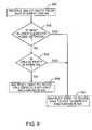
- FIG. 9is a flow diagram illustrating a process for a continuity control function of the multimedia subsystem to make call anchoring decisions for user elements that are initiating outgoing calls, according to one embodiment of the present invention.
- FIGS. 11A and 11Bshow a communication flow illustrating originating a call via the circuit-switched subsystem where call anchoring is provided in the multimedia subsystem according to one embodiment of the present invention.
- FIGS. 12A and 12Bshow a communication flow illustrating originating a call via the multimedia subsystem where call anchoring is provided in the multimedia subsystem according to one embodiment of the present invention.
- FIGS. 13A and 13Bshow a communication flow illustrating originating a call via the circuit-switched subsystem where call anchoring is provided in the multimedia subsystem according to an alternative embodiment of the present invention.
- FIG. 14shows a communication flow illustrating originating a call via the circuit-switched subsystem where call anchoring is not provided in the multimedia subsystem according to an alternative embodiment of the present invention.
- FIG. 15is a block representation of a service node according to one embodiment of the present invention.
- FIG. 16is a block representation of a user element according to one embodiment of the present invention.
- the present inventiondynamically determines whether call control for a call from a user element should be anchored in a multimedia subsystem (MS) or in a circuit-switched subsystem (CS) based on the location of the user element. Calls may be anchored in the MS regardless of whether the user element is currently served by a cellular network of the CS or a WLAN of the MS.
- the anchoring decisionis based on whether the user element is within an MS anchoring zone, which defines an area or areas where calls for the user element should be anchored in the MS. Accordingly, when the user element is outside of the MS anchoring zone, calls for the user element are not anchored in the MS. When the user element is within the MS anchoring zone, calls for the user element are anchored in the MS.
- a cellular network providing circuit-switched communicationsis referred to as a CS
- a WLAN providing packet communicationsis assumed to be part of or associated with the MS, which may be an Internet Protocol (IP) Multimedia Subsystem (IMS).
- IPInternet Protocol
- IMSInternet Multimedia Subsystem
- WLAN techniqueswireless communication techniques having relatively limited range, such as WLAN techniques, are referred to as local wireless communication techniques.
- local wireless communication techniquessupport packet-based communications, wherein cellular communication techniques will generally support circuit-switched communications.
- the wireless access for local wireless techniquesare of a limited range with respect to cellular access techniques.
- call control for originating and terminating calls in the CS or MS as well as transferring calls between the CS and MSis anchored at a continuity control function (CCF) in the MS.
- CCFcontinuity control function
- all call signaling for the callis passed through the CCF.
- the CCFis a service provided in the user element's home MS and may anchor the user element's CS calls and MS calls to provide call control and enable mobility across the CS and MS while maintaining CS calls or MS sessions.
- calls and sessionsare used interchangeably throughout the specification and claims.
- the CCFFor CS calls, the CCF operates to anchor the bearer path for calls originated or terminated through the CS by the user element at a media gateway, which is controlled by a media gateway controller of the home MS. Although the media gateway belongs to the home MS, the media gateway is preferably located in close proximity to the CS to save backhaul costs.
- the CCFemploys a Third Party Call Control function to provide call control in the CS.
- the CCFprovides call control by interacting with the user element and a remote endpoint to establish a bearer path directly between the user element and the remote endpoint through the MS.
- the CCFis addressable using public service identities (PSI).
- PSIpublic service identities
- a directory number associated with the CCFis used for routing call signaling messages within the CS.
- a uniform resource location (URL) associated with the CCFis used for routing call signaling messages within the MS.
- 3GPP TS 24.008(DTAP) is used in the CS, while the Session Initiation Protocol (SIP) is used in the MS to effect origination, termination, and transfer of calls.
- SIPSession Initiation Protocol
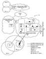
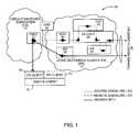
- FIG. 1a communication environment 10 is illustrated wherein a call is anchored in a home MS 12 while a CS 14 is currently serving a roaming user element 16 .
- the home MS 12 and the visited CS 14may support communications for the user element 16 depending on the location of the user element 16 .
- the user element 16includes a CS client 18 and an MS client 20 , which are configured to support circuit-switched communications via the CS 14 as well as packet communications via the MS 12 , respectively.
- a visited mobile switching center (VMSC) 22will support circuit-switched communications for the user element 16 .
- the VMSC 22may interact with the home MS 12 via a media gateway controller (MGC) 24 and an associated media gateway (MG) 26 , both of which are affiliated with the MS 12 .
- MMCmedia gateway controller
- MGmedia gateway
- the home MS 12may include various functions or entities, including an interrogating and serving call/session control function (I/S-CSCF) 28 , a CCF 30 , an application server (AS) 32 , and a home subscriber service (HSS) 34 .
- I/S-CSCFinterrogating and serving call/session control function
- ASapplication server
- HSShome subscriber service
- the interrogating CSCFprovides the standard I-CSCF functions
- the serving CSCFprovides standard S-CSCF functions. These functions are represented in the I/S-CSCF 28 for conciseness.
- the HSS 34may have a presence in both the CS 14 and the MS 12 .
- the HSS 34may include a home location resource component in a home CS.
- Call/session control functionsin the home MS 12 generally act as SIP proxies and provide various functions in association with call control, as will be appreciated by those skilled in the art.
- an interrogating CSCFmay interact with the HSS 34 to identify the serving CSCF (S-CSCF), which will be assigned to support a given user element.
- the HSS 34may maintain an association between a user element 16 and a particular CCF 30 that is assigned to the user element 16 .
- the HSS 34will assist in identifying a serving CSCF for the user element 16 , as well as keep an association between a particular CCF 30 and the user element 16 .
- the CCF PSI for the user element 16may be provisioned in the user element 16 to enable the user element 16 to initiate transfers and the like controlled by the CCF 30 . Alternatively, the CCF PSI may be transferred to the user element 16 upon network registration.
- the user element 16will have an S-CSCF assigned to it, and will use that S-CSCF to access the CCF 30 .
- a temporary S-CSCFmay be assigned to the user element 16 , and the temporary S-CSCF will be used to access the CCF 30 .
- the application servers 32may be invoked and placed within the call signaling path to implement any number of features or services.
- all signaling for the associated call or sessionis passed through the application service, which has the opportunity to process call signaling messages as necessary to implement the desired service.
- the CCF 30acts like a service, and as such, the I/S-CSCF 28 will operate to pass all call signaling messages for the call through the CCF 30 , thereby allowing the CCF 30 to act as an anchor for the call when the user element is within the MS anchoring zone.
- call signaling for the callpasses through the VMSC 22 , media gateway controller 24 , I/S-CSCF 28 , CCF 30 , and perhaps application server 32 , if a service is invoked, on its way toward a remote endpoint 36 .
- the access signaling legwhich is provided by the CS 14 , is anchored at the CCF 30 and extends through the I/S-CSCF 28 , media gateway controller 24 , the VMSC 22 , and CS client 18 of the user element 16 .
- the remote signaling leg toward the remote endpoint 36is anchored in the CCF 30 and extends through the I/S-CSCF 28 and the application server 32 .
- the CCF 30can maintain control of the call and provide any necessary call processing during the call. Further, if a call transfer is required, the CCF 30 maintains the remote signaling leg and establishes a new access signaling leg.
- the bearer path for the call illustrated in FIG. 1extends from the CS client 18 through the VMSC 22 and media gateway 26 on its way toward the remote endpoint 36 .
- the media gateway controller 24cooperates with the media gateway 26 , such that a circuit-switched connection may be established between the media gateway 26 and the CS client 18 via the VMSC 22 .
- the packet sessionmay be established for the call from the media gateway 26 through the home MS 12 toward the remote endpoint 36 .
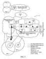
- a call supported by the MS client 20 of the user element 16is represented. Further, the user element 16 is within an MS anchoring zone. In this scenario, the call does not extend through the CS 14 , and will not employ the services of the VMSC 22 , media gateway controller 24 , or media gateway 26 . Instead, the MS client 20 will support call signaling directly with the MS 12 , and in particular with the CCF 30 via a serving-CSCF (S-CSCF) 40 .
- S-CSCFserving-CSCF
- the I/S-CSCF 28 and the S-CSCF 40may represent the same CSCF or different CSCFs, depending on how the user element 16 registers with the MS 12 .
- call signalingis anchored in the CCF 30 , wherein an access signaling leg is provided between the CCF 30 and the MS client 20 via the S-CSCF 40 .
- a remote signaling legis supported between the remote endpoint 36 and the CCF 30 via the S-CSCF 40 and any desired application servers 32 that may provide additional services in association with the call.
- the bearer pathwill extend from the MS client 20 toward the remote endpoint 36 via the MS 12 , without traveling through the CS 14 ( FIG. 1 ).
- the CCF 30anchors the call, such that a transfer is required, the remote signaling leg toward the remote endpoint 36 can be maintained, while the access signaling leg may be changed to facilitate the transfer from the home MS 12 to the CS 14 .
- the access signaling legs illustrated in FIGS. 1 and 2will be changed to support the transfer, while the remote signaling leg is maintained by the CCF 30 .
- Subsystem transfersenable the user element 16 to move between the CS 14 and the MS 12 while maintaining one or more active calls (voice sessions). Call transfers associated with a given call, including initial and subsequent transfers, are executed and controlled in the home MS 12 by the CCF 30 , upon a request received from the user element 16 . To enable such transfers, the CCF 30 is inserted into the signaling path of the calls by an S-CSCF ( 28 or 40 ). To anchor the signaling path, the CCF 30 will employ a back-to-back user agent function (B2BUA), which may operate as follows. When the user element 16 originates a call, the CCF 30 will terminate an access signaling leg from the user element 16 and establish a remote signaling leg toward the remote endpoint 36 .
- B2BUAback-to-back user agent function
- the CCF 30When terminating a call at the user element 16 , the CCF 30 will terminate a remote signaling leg from the remote endpoint 36 and establish an access signaling leg toward the user element 16 . Subsequently, the CCF 30 will coordinate call signaling between the access signaling leg and the remote signaling leg for the call.
- the CCF 30When the user element 16 is originating a call, the CCF 30 appears as a service provided by an application server, such as the application server 32 . In one embodiment, the CCF 30 is invoked as the first service in a chain of services. When the user element 16 is terminating a call, the CCF 30 is invoked as the last service in a chain of services. By locating the CCF 30 with respect to the other services in this manner, other applications associated with the call are anchored by the CCF 30 as part of the remote signaling leg of the call, and are therefore not impacted by transfers affecting the access signaling leg.
- a Mobile Subscriber Integrated Services Digital Network number (MSISDN) or other user element identifieris owned and controlled by the MS 12 to enable anchoring of incoming calls intended for the user element 16 at the CCF 30 .
- MSISDNMobile Subscriber Integrated Services Digital Network number
- PSTNpublic switched telephone network
- the CCF 30can take the necessary steps to find the user element 16 and route the call to the user element 16 , even if the user element 16 is in the CS 14 when the call arrives.
- the HSS 34may store filter criteria associated with the CCF 30 as part of the user element's subscription profile.
- the CCF filter criteriais downloaded to the currently assigned S-CSCF ( 28 or 40 ) as part of the initial filter criteria to use when the user element 16 registers with the MS 12 .
- This filter criteriais generally executed at the S-CSCF 40 (or 28 ) upon initiation of a call or session from the user element 16 or upon receipt of an incoming session intended for the user element 16 .
- This filter criteriawill instruct the S-CSCF 40 (or 28 ) to invoke the CCF 30 to control at least the bearer path for the call or session.
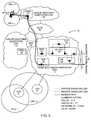
- the CS 14is shown as being associated with two cellular network cells CELL 1 and CELL 2 .
- the MS 12is shown with associated local wireless zones LWZ A and LWZ B.
- cells 1 and 2partially overlap one another.
- Local wireless zone Ais located within the area in which cells 1 and 2 overlap one another, while local wireless zone B is contained within cell 2 but not within cell 1 .
- a public switched telephone network (PSTN) 38is also associated with the MS 12 and the CS 14 .
- the PSTN 38supports an additional CS 14 ′, which is associated with cells 3 and 4 .
- the CS 14 ′may include a VMSC 22 ′.
- an MS anchoring zoneis defined to include all or most of the cells supported by the CS 14 and the local wireless zones supported by the MS 12 .
- the MS anchoring zoneis defined to include cell 1 and cell 2 of the CS 14 , the local wireless zones A and B, and the provider network having the network ID of 12345.
- the CS 14 ′ and the associated cells 3 and 4are not considered within the MS anchoring zone.
- local wireless zones A and Bdo not need to reside within cells 1 and 2 to be part of the MS anchoring zone. There are numerous ways to determine whether or not the user element 16 is within the MS anchoring zone.
- the MS anchoring zonemay be tied to a specific geographic area, wherein the geographic location of the user element 16 may be analyzed to determine whether the user element 16 is within the MS anchoring zone.
- the MS anchoring zoneis generally defined as being service areas for one or more cells ( 1 or 2 ), local wireless zones (A or B), or provider networks. These entities will be associated with IDs, wherein the user element 16 may recognize cell IDs, switch (VMSC) IDs, network IDs, local wireless zone IDs, and the like, and determine whether being served by one of these entities correlates to being within the MS anchoring zone.
- VMSCswitch
- the user element 16is within local wireless zone B, which is within cell 2 .
- callsmay be supported using cellular techniques through the CS client 18 or local wireless techniques through the MS client 20 . Determining whether to user the CS client 18 or the MS client 20 for an incoming or outgoing call is beyond the scope of the present invention.
- anchoring callswhen the user element 16 is within local wireless zone B, a determination is made to anchor calls at the CCF 30 of the MS 12 , because the user element 16 is within the MS anchoring zone, which was defined above.
- the local wireless network provider associated with the network ID 55555is part of the MS anchoring zone definition. Since the user element 16 is within the MS anchoring zone, calls are anchored at the CCF 30 of the MS 12 , even though communications are supported via the MS client 20 of the user element 16 and the resulting call is routed through the MS 12 instead of the CS 14 .
- FIG. 5assume the user element 16 moves to an area where communication access is provided via the VMSC 22 ′ of the CS 14 ′, and in particular, the user element 16 is in an area where cells 3 and 4 overlap.
- callsare anchored at the CCF 30 in the MS 12 .
- Such anchoringwould take place if the MS anchoring zone included cells 3 or 4 , the VMSC 22 ′, or the CS 14 ′ as part of the MS anchoring zone definition.
- callswould be anchored at the CCF 30 of the MS 12 if all calls were required to be anchored at the CCF 30 of the MS 12 , or if dynamic anchoring of the present invention was not employed.
- FIG. 6assume user element 16 is in the same location as that illustrated in FIG. 5 , and therefore the current communication access profile is the same as that of FIG. 5 .
- the MS anchoring zonedoes not include the current location of the user element 16 , and as such, cells 3 and 4 , the VMSC 22 ′, or the CS 14 ′, are not considered within the MS anchoring zone.
- callswill not be anchored at the CCF 30 of the MS 12 when the user element 16 is outside of the MS anchoring zone. Instead, the calls are routed directly between the user element 16 and the remote endpoint 36 without routing the call through the MS 12 or invoking the CCF 30 to play a role in controlling the call signaling associated with the call.
- the present inventionfunctions to determine whether a user element 16 is within an MS anchoring zone. If the user element 16 is within the MS anchoring zone, calls are anchored at the CCF 30 of the MS 12 . If the user element 16 is outside of the MS anchoring zone, calls are routed directly to or from a remote endpoint 36 without invoking the MS 12 , and in particular, the home MS 12 associated with the user element 16 .
- the MS anchoring zoneis defined to meet the desired communication efficiencies of the communication provider and reduce or minimize inefficient routing of calls through the home MS 12 of the user element 16 when the user element 16 is too far from the MS 12 or currently served by a network where such anchoring is undesirable.
- FIG. 7is a flow diagram where a user element 16 operates to determine where to anchor an outgoing call. Initially, the user element 16 may determine whether or not all calls should be anchored in the MS 12 (step 100 ). If all calls should be anchored in the MS 12 , the user element 16 may initiate a call with anchoring in the MS 12 (step 102 ). The details of initiating a call where the call is anchored in the MS 12 are provided further below.
- the user element 16will determine whether it is in the MS anchoring zone (step 104 ). If the user element 16 is within the MS anchoring zone, the user element 16 will initiate a call to be anchored in the MS 12 (step 102 ). If the user element 16 is not within the MS anchoring zone (step 104 ), the user element 16 may determine whether the called party is in the home MS 12 (step 106 ). If the called party is within the home MS 12 , the user element 16 may initiate a call to be anchored in the MS 12 (step 102 ). In this scenario, although the user element 16 is not within the MS anchoring zone, the fact that the called party is serviced by the home MS 12 is sufficient to warrant routing the call through the home MS 12 , because routing the call otherwise would not necessarily provide more efficient call routing.
- the user element 16may initiate the call directly without employing anchoring in the MS 12 (step 108 ). If the user element 16 is within a remote CS 14 ′, the call may be simply initiated and anchored within the remote CS 14 ′. If the user element 16 is supported by a remote MS (not illustrated), the call may be initiated and anchored in the remote MS.
- a flow diagramis provided for identifying and potentially defining an MS anchoring zone.
- This processcould be provided solely in the user element 16 or in the MS 12 with the assistance of the user element 16 .
- the MS anchoring zonemay be defined without involvement by the user element 16 .
- the processbegins when an active user element 16 is switching from a cellular to a local wireless access mode (step 200 ).
- the user element 16may identify and associate with available access nodes in a given area to effectively recognize a communication profile (step 202 ).
- the access nodesmay correspond to the base stations or access points associated with cells and local wireless zones, supporting switches, or recognizable service providers.
- the user element 16will be able to identify cell IDs, local wireless IDs, switch IDs, network IDs, and the like in a given area, such as a local wireless zone.
- the ability to communicate with the various access nodes or receive service from a given service providercan be used to develop a communication signature, which corresponds to anchoring data.
- the user element 16may upload the anchoring data to the CCF 30 for network-based decisioning (step 204 ).
- the CCF 30may look at the anchoring data for a given area to help determine and define an MS anchoring zone based on the current anchoring data and previously received anchoring data (step 206 ).
- the user element 16may process the anchoring data to define the MS anchoring zone, and as such, the CCF 30 need not be responsible for defining the MS anchoring zone or making the decision as to whether the user element 16 is within the MS anchoring zone.
- defining an MS anchoring zone and making the decision as to whether the user element 16 is within the MS anchoring zonemay be provided in the user element 16 or in various nodes within the MS 12 .
- FIGS. 9 and 10provide flow diagrams where the CCF 30 in the MS 12 determines whether calls being initiated from the user element 16 should be anchored at the CCF 30 in the MS 12 .
- the CCF 30will instruct the serving VMSC 22 to route the call to the CCF 30 for anchoring in the MS 12 .
- the CCF 30provides directions directly to the user element 16 , which will respond by initiating the call to the CCF 30 , such that the call can be anchored within the MS 12 .
- the CCF 30will receive the dialed digits from the user element 16 via any number of intelligent networking (IN) elements, such as the VMSC 22 (step 300 ).
- the CCF 30will determine whether the VMSC 22 is in the user element's home network, such as the CS 14 (step 302 ). If the VMSC 22 currently serving the user element 16 is within the CS 14 , the CCF 30 will instruct the VMSC 22 to route the call to the CCF 30 to employ anchoring in the MS 12 (step 304 ).
- the MS anchoring zoneis at least the cellular coverage area supported by the VMSC 22 .
- the CCF 30will determine whether the called party is within the home MS 12 for the user element 16 (step 306 ). If the called party is within the home MS 12 of the user element 16 , the CCF 30 will instruct the VMSC 22 to route the call to the CCF 30 to employ anchoring in the MS 12 (step 304 ).
- the CCF 30will instruct the VMSC 22 to route the call directly toward the endpoint 36 without employing anchoring in the MS 12 (step 308 ).
- the CCF 30will instruct the user element 16 to take the necessary action to invoke anchoring in the MS 12 , when such anchoring is desired.
- the CCF 30will ultimately received the dialed digits and current anchoring data from the user element 16 (step 400 ). This information may be provided using Unstructured Supplementary Service Data (USSD) messaging techniques.
- the CCF 30will analyze the anchoring data to determine if the user element 16 is within the MS anchoring zone (step 402 ). If the user element is within the MS anchoring zone (step 404 ), the CCF 30 will instruct the user element to initiate a call to the CCF 30 to effectively employ anchoring in the MS 12 (step 406 ).
- USSDUnstructured Supplementary Service Data
- the CCF 30will determine whether the called party is in the home MS 12 of the user element 16 (step 408 ). If the called party is in the home MS 12 of the user element 16 , the CCF 30 will instruct the user element 16 to initiate a call to the CCF 30 to employ anchoring in the MS 12 (step 406 ). If the called party is not within the home MS 12 of the user element 16 (step 408 ), the CCF 30 will instruct the user element 16 to initiate a call directly without employing anchoring in the MS 12 (step 410 ). Further details regarding initiating such calls and making decisions as to whether anchoring in the MS 12 is required are provided in the following communication flows.
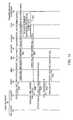
- a communication flowis provided to illustrate origination of a call from the CS client 18 of the user element 16 via the CS 14 , when the user element 16 is within the MS anchoring zone.
- the CS client 18will send a call setup message to its supporting VMSC 22 (step 500 ).
- the call setup messagewill identify the directory number of the remote endpoint 36 .
- An originating IN triggerwill cause the called party address for the remote endpoint 36 to be sent to the CCF 30 (step 502 ), which will store the called party address for later call completion.
- the CCF 30will return an IN routing message, telling the VMSC 22 to route the call toward the CCF PSI (CS) address (step 504 ).
- the VMSC 22will send an Integrated Services User Part (ISUP) Initial Address Message (IAM) to the media gateway controller 24 with the CS PSI for the CCF 30 (step 506 ).
- IAMInitial Address Message
- the VMSC 22will also provide a Call Proceeding message back to the CS client 18 of the user element 16 (step 508 ).
- This exchangeresults in a CS bearer leg being established from the CS client 18 to the media gateway 26 via the VMSC 22 (step 510 ).
- the media gateway controller 24will act as a user agent on behalf of the user element 16 .
- the media gateway controller 24Upon receiving the IAM from the VMSC 22 , the media gateway controller 24 will send an Invite to the I/S-CSCF 28 to initiate establishment of an MS bearer leg toward the CCF 30 from the media gateway 26 (step 512 ).
- the media gateway controller 24When generating the Invite, the media gateway controller 24 will identify the MS-based PSI for the CCF 30 in light of the CS-based PSI received in the IAM.
- the MS-based PSI for the CCF 30is the address to which the Invite is sent.
- the Invitewill also identify the user element 16 as the originator of the call.
- the Invitemay also indicate that the call was originated through the CS 14 .
- the I/S-CSCF 28will send the Invite to the CCF 30 (step 514 ), which will invoke a back-to-back user agent (B2BUA) and then take the necessary steps to complete the call (step 516 ) by associating the call to called party address of the remote endpoint 36 stored previously in step 502 .
- the CCF 30will send an Invite back to the I/S-CSCF 28 to complete the call (step 518 ).
- the Invitewill now include the address of the remote endpoint 36 or a supporting node with which a packet session can be established.
- the Invitewill identify the media gateway controller 24 of the media gateway 26 as the other endpoint for the packet session that will support the call.
- the I/S-CSCF 28will then send the Invite toward the remote endpoint 36 (step 520 ).
- the traditional session message exchange between the remote endpoint 36 and the media gateway controller 24will take place through the CCF 30 , which is the anchor point for call signaling, and the I/S0-CSCF 28 to prepare the respective remote endpoint 36 and media gateway 26 to support the MS bearer leg (step 522 ).
- the I/S-CSCF 28may receive various signaling back from the remote endpoint 36 , such as a 180 Ringing message (step 524 ).
- the 180 Ringing messageindicates that the call is being presented to the remote endpoint 36 .
- the I/S-CSCF 28will route all signaling messages through the CCF 30 , and as such, the 180 Ringing message is sent to the CCF 30 (step 526 ), which will forward the message back to the I/S-CSCF 28 (step 528 ).
- the I/S-CSCF 28will send the 180 Ringing message to the media gateway controller 24 (step 530 ).
- the MS bearer pathis effectively established (step 534 ), which means that the media gateway 26 and the remote endpoint 36 can send packets back and forth in association with the call.
- the media gateway controller 24will send an Address Complete Message (ACM) to the VMSC 22 (step 536 ), which will send an Alerting message to the user element 16 to indicate that call is being presented to the remote endpoint 36 (step 538 ).
- ACMAddress Complete Message
- the I/S-CSCF 28will receive a 200 OK message (step 540 ) and route the 200 OK message to the CCF 30 (step 542 ).
- the CCF 30will process the message if necessary, and then send the message back to the I/S-CSCF 28 (step 544 ), which will forward the 200 OK message to the media gateway controller 24 (step 546 ).
- the media gateway controller 24will send an Answer Message (ANM) to the VMSC 22 (step 548 ), which will send a Connect message to the CS client 18 (step 550 ) to indicate that the call has been answered.
- NAMAnswer Message
- the media gateway controller 24will provide appropriate signaling to the media gateway 26 , as well as send an acknowledgement (ACK) message back to the I/S-CSCF 28 (step 552 ).
- the I/S-CSCF 28will again forward the ACK to the CCF 30 (step 554 ), which will forward the message back to the I/S-CSCF 28 (step 556 ).
- the I/S-CSCF 28will then send the ACK toward the remote endpoint 36 (step 558 ).
- a CS/MS bearer pathis established between the CS client 18 of the user element 16 and the remote endpoint 36 via the media gateway 26 (step 560 ). Further, the call will be anchored in the MS 12 , with all call signaling associated with the call routed through the CCF 30 .
- the back-to-back user agent invoked by the CCF 30is the function that represents an endpoint for signaling associated with the remote signaling leg as well as an endpoint for the access signaling leg. The back-to-back user agent will provide any necessary processing or filtering and then relay messages over the respective access and remote signaling legs.
- a communication flowis provided for originating a call from the MS client 20 of the user element 16 , when the user element 16 is within the MS anchoring zone.
- the MS client 20 of the user element 16will register with the MS 12 , which will result in the user element 16 being assigned to the S-CSCF 40 (step not shown).
- the MS client 20 of the user element 16will send an Invite, which will be directed to the S-CSCF 40 (step 600 ).
- the Invitewill identify the remote endpoint address to which the call is intended, and will include an indication that the call will be supported by the MS client 20 through the MS 12 (without involving the CS 14 ).
- the S-CSCF 40will use the filter criteria associated with the user element 16 to determine that the call should be anchored in the MS 12 and call routing should be sent to the CCF 30 , and as such, will send the Invite to the CCF 30 (step 602 ).
- the CCF 30will invoke the back-to-back user agent and take the necessary steps to complete the session (step 604 ).
- the CCF 30will send an Invite toward the remote endpoint 36 via the S-CSCF 40 (steps 606 and 608 ).
- the MS client 20 of the user element 16 and the remote endpoint 36will provide the requisite session message exchange to support an MS bearer path via the S-CSCF 40 and CCF 30 (step 610 ).
- the S-CSCF 40will receive a 180 Ringing message (step 612 ).
- the 180 Ringing messageis sent to the CCF 30 (step 614 ), which will send the 180 Ringing message back to the S-CSCF 40 (step 616 ).
- the S-CSCF 40will ensure that all call signaling is routed through the CCF 30 .
- the S-CSCF 40will send the 180 Ringing message to the MS client 20 of the user element 16 (step 618 ), wherein the user element 16 and the remote endpoint 36 will exchange the requisite PRACK and 200 OK messages via the S-CSCF 40 and the CCF 30 (step 620 ).
- the S-CSCF 40When the call is answered at the remote endpoint 36 , the S-CSCF 40 will receive a 200 OK message (step 622 ). The S-CSCF 40 will route the 200 OK message through the CCF 30 (steps 624 and 626 ) and then send the 200 OK message to the MS client 20 of the user element 16 (step 628 ). The MS client 20 of the user element 16 will respond with an Acknowledgement message, which is received at the S-CSCF 40 (step 630 ). The S-CSCF 40 will send the Acknowledgement message through the CCF 30 (steps 632 and 634 ) and then forward the Acknowledgement message toward the remote endpoint 36 (step 636 ).
- an MS bearer pathis established between the MS client 20 of the user element 16 and the remote endpoint 36 through the MS 12 , without engaging the CS 14 (step 638 ).
- all call signalingis routed through the CCF 30 by the S-CSCF 40 , such that the CCF 30 may remain an anchor for the call in case additional services are required or a transfer of the bearer path through the CS 14 is necessary or desired.
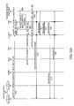
- an alternative techniqueis illustrated where the user element 16 will initiate outgoing calls to the remote endpoint 36 by initiating a call to the CCF 30 , when the user element 16 is within the MS anchoring zone.
- An alternate signaling channelsuch as an USSD channel, is used to provide information identifying anchoring data and the remote endpoint 36 to the CCF 30 .
- the CCF 30includes decision logic to determine if and when to invoke the CCF 30 as an anchoring point for call signaling.
- the user element 16Upon determining a need to initiate a call, the user element 16 will employ a USSD operation to determine if call should be anchored at the CCF 30 .
- the user's identity, called party number, call reference, anchoring data, and any other information required to complete the call to the remote endpoint 36is sent in a USSD message to the VMSC 22 (step 700 ).
- the VMSC 22will forward the USSD message to the CCF 30 or to the user's home location resource (HLR) (not shown), which will forward the message to the CCF 30 (step 702 ).
- the CCF 30will process the information in the USSD message to determine whether the user element 16 is within the MS anchoring zone (step 704 ).
- the CCF 30will send to the VMSC 22 a USSD message including the call reference information and the instructions to initiate the call via the MS 12 using the CCF PSI (step 706 ).
- the VMSC 22will forward the USSD message to the user element 16 (step 708 ).
- the CS client 18 of the user element 16Upon receipt of the USSD message, the CS client 18 of the user element 16 will send a Setup message to the VMSC 22 (step 710 ).
- the Setup messagewill indicate that a call is being originated to the CCF 30 using the CS PSI of the CCF 30 and may include a called party sub-address along with the call reference (CALL REF).
- the VMSC 22will respond with a Call Proceeding message, which is received by the CS client 18 of the user element 16 (step 712 ).
- the VMSC 22Upon establishing resources for the originating leg, the VMSC 22 will attempt to complete the call to the CCF 30 via the media gateway controller 24 . As such, the VMSC 22 will send an IAM to the media gateway controller 24 (step 714 ). The IAM will provide the call reference and identify the CS PSI for the CCF 30 . In response, the media gateway controller 24 will send an Invite intended for the CCF 30 using the MS PSI for the CCF 30 and indicate that a call is being initiated from the CS 14 via the media gateway controller 24 . The Invite will be received by the I/S-CSCF 28 ′ (step 716 ), which will send the Invite to the CCF 30 (step 718 ).
- the CCF 30will use the call reference or other means, such as calling party number as available, to associate the information in the Invite with that provided by the USSD information.
- the CCF 30will terminate the incoming call leg that was originated to the CS PSI of the CCF 30 , and will invoke a back-to-back user agent to originate a session to the remote endpoint 36 , which was the originally called party.
- the CCF 30may access the HSS 34 to obtain the address for the S-CSCF 40 and then route the call toward the remote endpoint 36 via the S-CSCF 40 or the CCF 30 may route the call to the S-CSCF via an I-CSCF.
- a conversionmay be necessary from the directory number associated with the remote endpoint 36 and the address necessary for routing the Invite.
- the CCF 30will provide this functionality. Once the Invite is received by the S-CSCF 40 (step 720 ), the Invite is sent toward the remote endpoint 36 (step 722 ). The media gateway controller 24 and the remote endpoint 36 will then provide the requisite session message exchange, such that an MS bearer path can be established between the media gateway 26 and the remote endpoint 36 (step 724 ). The messages exchanged during the session message exchange will be routed through the CCF 30 and the S-CSCF 40 .
- the S-CSCF 40When the call is presented to the remote endpoint 36 , the S-CSCF 40 will receive a 180 Ringing message (step 726 ), and will forward the 180 Ringing message to the CCF 30 (step 728 ).
- the CCF 30will send the 180 Ringing message to the I/S-CSCF 28 ′ (step 730 ), which will send a 180 Ringing message to the media gateway controller 24 (step 732 ).
- the media gateway controller 24will send an ACM to the VMSC 22 to indicate that the call is being presented to the remote endpoint 36 (step 734 ).
- the VMSC 22will then send an appropriate Alerting message to the CS client of the user element 16 (step 736 ). Meanwhile, the PRACK and 200 OK message exchange will take place between the media gateway controller 24 and the remote endpoint 36 via the S-CSCF 40 and the CCF 30 (step 738 ).
- the S-CSCF 40When the remote endpoint 36 is answered, the S-CSCF 40 will receive a 200 OK message (step 740 ), and send a 200 OK message to the CCF 30 (step 742 ).
- the CCF 30will send a 200 OK message to the I/S-CSCF 28 ′ (step 744 ), which will send the 200 OK message to the media gateway controller 24 (step 746 ).
- the media gateway controller 24will send an ANM to the VMSC 22 (step 748 ), which will send a Connect message to the CS client 18 of the user element 16 (step 750 ).
- the media gateway controller 24will also send an Acknowledgement in response to the 200 OK message to the I/S-CSCF 28 ′ (step 752 ).
- the I/S-CSCF 28 ′will forward the Acknowledgement to the CCF 30 (step 754 ), which will send the Acknowledgement message to the S-CSCF 40 (step 756 ).
- the S-CSCF 40will then send the Acknowledgement message toward the remote endpoint 36 (step 758 ). Again, all messaging is routed through the CCF 30 by the S-CSCF 40 .
- a CS/MS bearer pathis established between the CS client 18 of the user element 16 and the remote endpoint 36 via the media gateway 26 and the VMSC 22 (step 760 ). The call is again anchored in the MS 12 .
- FIG. 14an alternative technique is illustrated where the user element 16 will initiate outgoing calls directly to the remote endpoint 36 without invoking routing the call to the CCF 30 , when the user element 16 is not within the MS anchoring zone.
- the USSD channelis used to provide information identifying anchoring data and the remote endpoint 36 to the CCF 30 .
- the CCF 30determines if and when to invoke the CCF 30 as an anchoring point for call signaling.
- the user element 16Upon determining a need to initiate a call, the user element 16 will employ a USSD operation to determine if call should be anchored at the CCF 30 .
- the user's identity, called party number, call reference, anchoring data, and any other information required to complete the call to the remote endpoint 36is sent in a USSD message to the VMSC 22 (step 800 ).
- the VMSC 22will forward the USSD message to the CCF 30 or to the user's home location resource (HLR) (not shown), which will forward the message to the CCF 30 (step 802 ).
- the CCF 30will process the information in the USSD message to determine whether the user element 16 is within the MS anchoring zone (step 804 ).
- the CCF 30will send to the VMSC 22 a USSD message including the call reference information and the instructions to directly or locally initiate the call to the remote endpoint 36 using the directory number of the called party instead of via the MS 12 using the CCF PSI (step 806 ).
- the VMSC 22will forward the USSD message to the user element 16 (step 808 ).
- the CS client 18 of the user element 16Upon receipt of the USSD message, the CS client 18 of the user element 16 will send a Setup message to the VMSC 22 (step 810 ).
- the Setup messagewill indicate that a call is being directly originated to the remote endpoint 36 using the directory number of the called party.
- the VMSC 22will respond with a Call Proceeding message, which is received by the CS client 18 of the user element 16 (step 812 ).
- the VMSC 22Upon establishing resources for the originating leg, the VMSC 22 will attempt to complete the call to the remote endpoint 36 . As such, the VMSC 22 will send an IAM directly toward the remote endpoint 36 without invoking the services of the CCF 30 (step 814 ).
- a service node 44is provided according to one embodiment of the present invention.
- the service node 44may reside in the MS 12 and include a control system 46 and associated memory 48 to provide the functionality for any one or a combination of the following: the CCF 30 , the S-CSCF 40 , and the I/S-CSCF 28 .
- the control system 46will also be associated with a communication interface 50 to facilitate communications with any entity affiliated with the MS 12 or appropriately associated networks.
- the user element 16may include a control system 52 having sufficient memory 54 to support operation of the CS client 18 and the MS client 20 .
- the control system 52will cooperate closely with a communication interface 56 to allow the CS client 18 and the MS client 20 to facilitate communications over the CS 14 or the MS 12 as described above.
- the control system 52may also be associated with a user interface 58 , which will facilitate interaction with the user.
- the user interface 58may include a microphone and speaker to facilitate voice communications with the user, as well as a keypad and display to allow the user to input and view information.
Landscapes
- Engineering & Computer Science (AREA)
- Computer Networks & Wireless Communication (AREA)
- Signal Processing (AREA)
- Mobile Radio Communication Systems (AREA)
Abstract
Description
Claims (27)
Priority Applications (1)
| Application Number | Priority Date | Filing Date | Title |
|---|---|---|---|
| US11/452,743US8180338B1 (en) | 2006-06-14 | 2006-06-14 | Selective call anchoring in a multimedia subsystem |
Applications Claiming Priority (1)
| Application Number | Priority Date | Filing Date | Title |
|---|---|---|---|
| US11/452,743US8180338B1 (en) | 2006-06-14 | 2006-06-14 | Selective call anchoring in a multimedia subsystem |
Publications (1)
| Publication Number | Publication Date |
|---|---|
| US8180338B1true US8180338B1 (en) | 2012-05-15 |
Family
ID=46033271
Family Applications (1)
| Application Number | Title | Priority Date | Filing Date |
|---|---|---|---|
| US11/452,743Active2028-10-07US8180338B1 (en) | 2006-06-14 | 2006-06-14 | Selective call anchoring in a multimedia subsystem |
Country Status (1)
| Country | Link |
|---|---|
| US (1) | US8180338B1 (en) |
Cited By (9)
| Publication number | Priority date | Publication date | Assignee | Title |
|---|---|---|---|---|
| US20070280162A1 (en)* | 2006-06-02 | 2007-12-06 | Deshpande Manoj M | Method and system for dynamic anchoring of circuit-switched calls |
| US20080160991A1 (en)* | 2006-12-27 | 2008-07-03 | Nortel Networks Limited | Voice continuity among user terminals |
| US20100202447A1 (en)* | 2007-10-25 | 2010-08-12 | Huawei Technologies Co., Ltd. | Call Transfer Method, System and Device |
| US20100216445A1 (en)* | 2007-10-25 | 2010-08-26 | Huawei Technologies Co., Ltd. | Call Transfer Method, System and Device |
| US20110289219A1 (en)* | 2010-05-19 | 2011-11-24 | Avaya Inc. | Sip anchor points to populate common communication logs |
| US8644298B1 (en) | 2007-09-12 | 2014-02-04 | Genband Us Llc | Adding a service control channel after session establishment |
| US20140040350A1 (en)* | 2007-12-21 | 2014-02-06 | Nederlandse Organisatie Voor Toegepast-Natuurwetenschappelijk Onderzoek Tno | Method And System For Transmitting A Multimedia Stream |
| US8811954B1 (en) | 2005-10-31 | 2014-08-19 | Genband Us Llc | Network domain selection |
| US8886789B2 (en)* | 2010-05-19 | 2014-11-11 | Avaya Inc. | SIP monitoring and control anchor points |
Citations (68)
| Publication number | Priority date | Publication date | Assignee | Title |
|---|---|---|---|---|
| US5497411A (en) | 1994-03-14 | 1996-03-05 | Pellerin; Joseph C. E. | Telecommunications card-access system |
| US6067453A (en) | 1996-10-25 | 2000-05-23 | Pt Pasifik Satelit Nusantara | Satellite-based direct access telecommunications systems |
| WO2000060785A1 (en) | 1999-04-01 | 2000-10-12 | Nokia Mobile Phones Limited | Apparatus and associated method for communicating multimedia information upon a communication link |
| WO2001003450A1 (en) | 1999-06-30 | 2001-01-11 | Nokia Corporation | Bearer adapter management at a gateway server |
| US6208627B1 (en) | 1997-12-10 | 2001-03-27 | Xircom, Inc. | Signaling and protocol for communication system with wireless trunk |
| WO2001022657A1 (en) | 1999-09-23 | 2001-03-29 | Nokia Networks Oy | Triggering of intelligent network service |
| US20010055982A1 (en) | 2000-06-26 | 2001-12-27 | Oki Electric Industry Co., Ltd. | Call connection management equipment for wireless mobile communication network |
| US6353596B1 (en) | 1996-04-12 | 2002-03-05 | Lucent Technologies Inc. | System and method for multipoint-to-multipoint multicasting |
| US20020133600A1 (en) | 2001-03-13 | 2002-09-19 | Brian Williams | Method and apparatus for establishing a protocol proxy for a mobile host terminal in a multimedia session |
| US20020188562A1 (en) | 2001-06-07 | 2002-12-12 | Yoichiro Igarashi | Billing system, and device constituting same |
| US20030027569A1 (en) | 2001-07-31 | 2003-02-06 | Ejzak Richard Paul | Communication system for providing roaming between an internet protocol multimedia system and a circuit-switched domain |
| US20030148765A1 (en) | 2002-02-06 | 2003-08-07 | Xiaomin Ma | Methods and systems for improving utilization of traffic channels in a mobile communications network |
| US6614897B1 (en) | 1998-03-20 | 2003-09-02 | British Telecommunications Public Limited Company | Service in a communications network |
| US20030174688A1 (en) | 1998-11-13 | 2003-09-18 | Lucent Technologies Inc. | Subnetwork layer for a multimedia mobile network |
| US20040002335A1 (en) | 2002-06-26 | 2004-01-01 | Pan Shaowei | Method and apparatus for implementing bi-directional soft handovers between wireless networks without carrier control |
| US20040003046A1 (en) | 2001-12-12 | 2004-01-01 | 3Com Corporation | System and methods for providing instant services in an internet protocol network |
| US20040028080A1 (en) | 2002-08-06 | 2004-02-12 | Harish Samarasinghe | Method of defining a SIP message body for communications between core network elements |
| WO2004019173A2 (en) | 2002-08-20 | 2004-03-04 | Ixi Mobile Inc. | A method, system and computer readable medium for providing an output signal having a theme to a device in a short distance wireless network |
| US20040067754A1 (en)* | 2002-10-08 | 2004-04-08 | Docomo Communications Laboratories Usa, Inc. | System and method for supporting quality of service in vertical handovers between heterogeneous networks |
| US6721565B1 (en) | 2000-08-07 | 2004-04-13 | Lucent Technologies Inc. | Handover of wireless calls between systems supporting circuit and packet call models |
| CA2501991A1 (en) | 2002-10-18 | 2004-04-29 | Kineto Wireless, Inc. | Apparatus and method for extending the coverage area of a licensed wireless communication system using an unlicensed wireless communication system |
| US20040157600A1 (en) | 2001-02-13 | 2004-08-12 | Martin Stumpert | Method for determining whether to grant access of a user equipment to a radio access network |
| WO2004073279A1 (en) | 2003-02-15 | 2004-08-26 | Telefonaktiebolaget Lm Ericsson (Publ) | Conversational bearer negotiation |
| US6801615B2 (en) | 2002-12-23 | 2004-10-05 | Siemens Information And Communication Networks, Inc. | Carrier identification codes (CIC) conversion |
| US20040219905A1 (en) | 2003-05-02 | 2004-11-04 | Steven Blumenthal | Authentication of mobile devices via proxy device |
| US20040229469A1 (en) | 2003-05-13 | 2004-11-18 | Marsh Philbert Francis | Photodiode passivation technique |
| US20040246990A1 (en) | 2003-06-04 | 2004-12-09 | Nokia Corporation | System and method for handing over a call from a packet-switched network to a circuit-switched network |
| US20050002407A1 (en) | 2003-05-01 | 2005-01-06 | Interdigital Technology Corporation | Method and apparatus for delivery of data-based/voice services over piconets and wireless LANs (WLANs) coupled to 3GPP devices including protocol architecture and information elements relating to short message services (SMS) over WLANs |
| US20050003797A1 (en) | 2003-07-02 | 2005-01-06 | Baldwin Johnny E. | Localized cellular awareness and tracking of emergencies |
| US20050003821A1 (en) | 2003-05-21 | 2005-01-06 | Nortel Networks Limited | Call transfer for an integrated wireline and wireless service |
| US6961774B1 (en) | 2001-08-02 | 2005-11-01 | Cisco Technology, Inc. | System and method for performing hand-offs between internet protocol (IP) core networks in the wireless domain |
| US20050243870A1 (en) | 2004-04-14 | 2005-11-03 | Balogh Dan A | Method of transferring call transition messages between network controllers of different radio technologies |
| US20050245261A1 (en) | 2004-04-14 | 2005-11-03 | Ejzak Richard P | Method of handing off a packet switched to a circuit switched call |
| US6970459B1 (en) | 1999-05-13 | 2005-11-29 | Intermec Ip Corp. | Mobile virtual network system and method |
| US20050265304A1 (en)* | 2000-03-13 | 2005-12-01 | Dong-Hoon Kim | Common subscriber managing apparatus and method based on functional modeling of a common subscriber server for use in an ALL-IP network |
| US20050286531A1 (en) | 2002-07-16 | 2005-12-29 | Markku Tuohino | Optimized routing between communication networks |
| US20060002355A1 (en) | 2004-07-05 | 2006-01-05 | Samsung Electronics Co., Ltd. | Method and system for providing handoff between mobile communication network and wireless local area network, and switching device therefor |
| US20060002380A1 (en) | 2000-11-03 | 2006-01-05 | Insors Integrated Communications, Inc. | Method and dial plan for packet based voice communications functionality |
| US6999770B2 (en)* | 2003-12-30 | 2006-02-14 | Motorola, Inc. | Selective hairpinning of calls through another network |
| US20060034270A1 (en) | 2004-08-10 | 2006-02-16 | Oliver Haase | Method and apparatus for call routing via gateway brokering |
| US20060083199A1 (en) | 2004-10-15 | 2006-04-20 | Yang Jianhao M | System, method, and device for handing off between voice over internet protocol over wireless access sessions and CDMA circuit switched voice sessions |
| US20060094431A1 (en)* | 2004-11-01 | 2006-05-04 | Nokia Corporation | Method, system and mobile station for handing off communications from a cellular radio access network to an unlicensed mobile access network |
| US20060142004A1 (en) | 2004-12-23 | 2006-06-29 | Haixiang He | Method and apparatus to intelligently perform scanning and assist scanning by profiling scanning history |
| US20060187904A1 (en) | 2005-02-21 | 2006-08-24 | Makoto Oouchi | VoIP gateway apparatus |
| US7099309B2 (en) | 2003-10-10 | 2006-08-29 | Air-Bank Llc | Using a handheld communication device with a hot spot network |
| WO2006097837A1 (en) | 2005-03-17 | 2006-09-21 | Nortel Networks Limited | Circuit-switched and multimedia subsystem voice continuity |
| US20060217112A1 (en) | 2005-03-23 | 2006-09-28 | Richard Mo | System And Method For A Virtual Mobile Network |
| WO2006105732A1 (en) | 2005-04-05 | 2006-10-12 | Huawei Technologies Co., Ltd. | A handoff method of circuit switching call connection |
| US20060268928A1 (en) | 2005-05-17 | 2006-11-30 | Farhad Barzegar | Method and apparatus for routing a call to a dual mode wireless device |
| WO2006126072A1 (en) | 2005-05-27 | 2006-11-30 | Nortel Networks Limited | Circuit-switched and multimedia subsystem voice continuity with bearer path interruption |
| US20070004415A1 (en) | 2003-10-03 | 2007-01-04 | Saied Abedi | Soft handover |
| US20070014281A1 (en) | 2005-06-15 | 2007-01-18 | Azaire Networks | Voice call continuity application server between IP-CAN and CS networks |
| WO2007023358A2 (en) | 2005-08-22 | 2007-03-01 | Nortel Networks Limited | Multimedia subsystem service control for circuit-switched subsystem calls |
| US20070066304A1 (en) | 2005-09-07 | 2007-03-22 | Samsung Electronics Co., Ltd. | Method and apparatus for connecting to stable access point using connection history |
| US20070072605A1 (en) | 2005-09-29 | 2007-03-29 | Poczo Gabriella R | Seamless mobility management with service detail records |
| US7206582B2 (en) | 2004-12-27 | 2007-04-17 | Newstep Networks Inc. | Method, system and apparatus for call path reconfiguration |
| US20070100981A1 (en) | 2005-04-08 | 2007-05-03 | Maria Adamczyk | Application services infrastructure for next generation networks including one or more IP multimedia subsystem elements and methods of providing the same |
| US20070206568A1 (en) | 2006-03-02 | 2007-09-06 | Andrew Silver | Call flow system and method use in legacy telecommunication system |
| US7313666B1 (en) | 2002-08-10 | 2007-12-25 | Cisco Technology, Inc. | Methods and apparatus for longest common prefix based caching |
| US20080025263A1 (en) | 2006-06-16 | 2008-01-31 | Nokia Corporation | Apparatus and method for transferring PDP context information for a terminal in the case of intersystem handover |
| WO2008038101A2 (en) | 2006-09-29 | 2008-04-03 | Nortel Networks Limited | Enterprise mobility |
| US20080160991A1 (en) | 2006-12-27 | 2008-07-03 | Nortel Networks Limited | Voice continuity among user terminals |
| US20080268818A1 (en) | 2005-10-21 | 2008-10-30 | Ralf Keller | System and Method for Selecting a Subsystem for Call Termination |
| US7492886B1 (en) | 1998-08-04 | 2009-02-17 | At&T Intellectual Property Ii, L.P. | Method for allocating network resources |
| US20090190579A1 (en) | 2005-04-27 | 2009-07-30 | Andreas Witzel | Service routing decision entity |
| US7664495B1 (en) | 2005-04-21 | 2010-02-16 | At&T Mobility Ii Llc | Voice call redirection for enterprise hosted dual mode service |
| US20100124897A1 (en) | 2008-01-04 | 2010-05-20 | Edge Stephen W | Support of voice call continuity (VCC) for wireless emergency calls |
| US7729489B2 (en) | 2006-04-12 | 2010-06-01 | Cisco Technology, Inc. | Transferring a communications exchange |
- 2006
- 2006-06-14USUS11/452,743patent/US8180338B1/enactiveActive
Patent Citations (78)
| Publication number | Priority date | Publication date | Assignee | Title |
|---|---|---|---|---|
| US5497411A (en) | 1994-03-14 | 1996-03-05 | Pellerin; Joseph C. E. | Telecommunications card-access system |
| US6353596B1 (en) | 1996-04-12 | 2002-03-05 | Lucent Technologies Inc. | System and method for multipoint-to-multipoint multicasting |
| US6067453A (en) | 1996-10-25 | 2000-05-23 | Pt Pasifik Satelit Nusantara | Satellite-based direct access telecommunications systems |
| US6208627B1 (en) | 1997-12-10 | 2001-03-27 | Xircom, Inc. | Signaling and protocol for communication system with wireless trunk |
| US6614897B1 (en) | 1998-03-20 | 2003-09-02 | British Telecommunications Public Limited Company | Service in a communications network |
| US7492886B1 (en) | 1998-08-04 | 2009-02-17 | At&T Intellectual Property Ii, L.P. | Method for allocating network resources |
| US20030174688A1 (en) | 1998-11-13 | 2003-09-18 | Lucent Technologies Inc. | Subnetwork layer for a multimedia mobile network |
| WO2000060785A1 (en) | 1999-04-01 | 2000-10-12 | Nokia Mobile Phones Limited | Apparatus and associated method for communicating multimedia information upon a communication link |
| US6970459B1 (en) | 1999-05-13 | 2005-11-29 | Intermec Ip Corp. | Mobile virtual network system and method |
| WO2001003450A1 (en) | 1999-06-30 | 2001-01-11 | Nokia Corporation | Bearer adapter management at a gateway server |
| WO2001022657A1 (en) | 1999-09-23 | 2001-03-29 | Nokia Networks Oy | Triggering of intelligent network service |
| US20050265304A1 (en)* | 2000-03-13 | 2005-12-01 | Dong-Hoon Kim | Common subscriber managing apparatus and method based on functional modeling of a common subscriber server for use in an ALL-IP network |
| US20010055982A1 (en) | 2000-06-26 | 2001-12-27 | Oki Electric Industry Co., Ltd. | Call connection management equipment for wireless mobile communication network |
| US6721565B1 (en) | 2000-08-07 | 2004-04-13 | Lucent Technologies Inc. | Handover of wireless calls between systems supporting circuit and packet call models |
| US20060002380A1 (en) | 2000-11-03 | 2006-01-05 | Insors Integrated Communications, Inc. | Method and dial plan for packet based voice communications functionality |
| US20040157600A1 (en) | 2001-02-13 | 2004-08-12 | Martin Stumpert | Method for determining whether to grant access of a user equipment to a radio access network |
| US20020133600A1 (en) | 2001-03-13 | 2002-09-19 | Brian Williams | Method and apparatus for establishing a protocol proxy for a mobile host terminal in a multimedia session |
| US20020188562A1 (en) | 2001-06-07 | 2002-12-12 | Yoichiro Igarashi | Billing system, and device constituting same |
| US20030027569A1 (en) | 2001-07-31 | 2003-02-06 | Ejzak Richard Paul | Communication system for providing roaming between an internet protocol multimedia system and a circuit-switched domain |
| US6961774B1 (en) | 2001-08-02 | 2005-11-01 | Cisco Technology, Inc. | System and method for performing hand-offs between internet protocol (IP) core networks in the wireless domain |
| US20040003046A1 (en) | 2001-12-12 | 2004-01-01 | 3Com Corporation | System and methods for providing instant services in an internet protocol network |
| US20030148765A1 (en) | 2002-02-06 | 2003-08-07 | Xiaomin Ma | Methods and systems for improving utilization of traffic channels in a mobile communications network |
| US20040002335A1 (en) | 2002-06-26 | 2004-01-01 | Pan Shaowei | Method and apparatus for implementing bi-directional soft handovers between wireless networks without carrier control |
| US20050286531A1 (en) | 2002-07-16 | 2005-12-29 | Markku Tuohino | Optimized routing between communication networks |
| US20040028080A1 (en) | 2002-08-06 | 2004-02-12 | Harish Samarasinghe | Method of defining a SIP message body for communications between core network elements |
| US7313666B1 (en) | 2002-08-10 | 2007-12-25 | Cisco Technology, Inc. | Methods and apparatus for longest common prefix based caching |
| WO2004019173A2 (en) | 2002-08-20 | 2004-03-04 | Ixi Mobile Inc. | A method, system and computer readable medium for providing an output signal having a theme to a device in a short distance wireless network |
| US20040067754A1 (en)* | 2002-10-08 | 2004-04-08 | Docomo Communications Laboratories Usa, Inc. | System and method for supporting quality of service in vertical handovers between heterogeneous networks |
| CA2501991A1 (en) | 2002-10-18 | 2004-04-29 | Kineto Wireless, Inc. | Apparatus and method for extending the coverage area of a licensed wireless communication system using an unlicensed wireless communication system |
| US6801615B2 (en) | 2002-12-23 | 2004-10-05 | Siemens Information And Communication Networks, Inc. | Carrier identification codes (CIC) conversion |
| US20040249887A1 (en) | 2003-02-15 | 2004-12-09 | Miguel-Angel Garcia-Martin | Conversational bearer negotiation |
| WO2004073279A1 (en) | 2003-02-15 | 2004-08-26 | Telefonaktiebolaget Lm Ericsson (Publ) | Conversational bearer negotiation |
| US20050002407A1 (en) | 2003-05-01 | 2005-01-06 | Interdigital Technology Corporation | Method and apparatus for delivery of data-based/voice services over piconets and wireless LANs (WLANs) coupled to 3GPP devices including protocol architecture and information elements relating to short message services (SMS) over WLANs |
| US20040219905A1 (en) | 2003-05-02 | 2004-11-04 | Steven Blumenthal | Authentication of mobile devices via proxy device |
| US20040229469A1 (en) | 2003-05-13 | 2004-11-18 | Marsh Philbert Francis | Photodiode passivation technique |
| US20050003821A1 (en) | 2003-05-21 | 2005-01-06 | Nortel Networks Limited | Call transfer for an integrated wireline and wireless service |
| US20040246990A1 (en) | 2003-06-04 | 2004-12-09 | Nokia Corporation | System and method for handing over a call from a packet-switched network to a circuit-switched network |
| US20050003797A1 (en) | 2003-07-02 | 2005-01-06 | Baldwin Johnny E. | Localized cellular awareness and tracking of emergencies |
| US20070004415A1 (en) | 2003-10-03 | 2007-01-04 | Saied Abedi | Soft handover |
| US7099309B2 (en) | 2003-10-10 | 2006-08-29 | Air-Bank Llc | Using a handheld communication device with a hot spot network |
| US6999770B2 (en)* | 2003-12-30 | 2006-02-14 | Motorola, Inc. | Selective hairpinning of calls through another network |
| US20050243870A1 (en) | 2004-04-14 | 2005-11-03 | Balogh Dan A | Method of transferring call transition messages between network controllers of different radio technologies |
| US20050245261A1 (en) | 2004-04-14 | 2005-11-03 | Ejzak Richard P | Method of handing off a packet switched to a circuit switched call |
| US20060002355A1 (en) | 2004-07-05 | 2006-01-05 | Samsung Electronics Co., Ltd. | Method and system for providing handoff between mobile communication network and wireless local area network, and switching device therefor |
| US20060034270A1 (en) | 2004-08-10 | 2006-02-16 | Oliver Haase | Method and apparatus for call routing via gateway brokering |
| US20060083199A1 (en) | 2004-10-15 | 2006-04-20 | Yang Jianhao M | System, method, and device for handing off between voice over internet protocol over wireless access sessions and CDMA circuit switched voice sessions |
| US20060094431A1 (en)* | 2004-11-01 | 2006-05-04 | Nokia Corporation | Method, system and mobile station for handing off communications from a cellular radio access network to an unlicensed mobile access network |
| US20060142004A1 (en) | 2004-12-23 | 2006-06-29 | Haixiang He | Method and apparatus to intelligently perform scanning and assist scanning by profiling scanning history |
| US7206582B2 (en) | 2004-12-27 | 2007-04-17 | Newstep Networks Inc. | Method, system and apparatus for call path reconfiguration |
| US20060187904A1 (en) | 2005-02-21 | 2006-08-24 | Makoto Oouchi | VoIP gateway apparatus |
| WO2006097837A1 (en) | 2005-03-17 | 2006-09-21 | Nortel Networks Limited | Circuit-switched and multimedia subsystem voice continuity |
| US20060209805A1 (en) | 2005-03-17 | 2006-09-21 | Nortel Networks Limited | Circuit-switched and multimedia subsystem voice continuity |
| US20060217112A1 (en) | 2005-03-23 | 2006-09-28 | Richard Mo | System And Method For A Virtual Mobile Network |
| WO2006105732A1 (en) | 2005-04-05 | 2006-10-12 | Huawei Technologies Co., Ltd. | A handoff method of circuit switching call connection |
| EP1816877A1 (en) | 2005-04-05 | 2007-08-08 | Huawei Technologies Co., Ltd. | A handoff method of circuit switching call connection |
| US20070100981A1 (en) | 2005-04-08 | 2007-05-03 | Maria Adamczyk | Application services infrastructure for next generation networks including one or more IP multimedia subsystem elements and methods of providing the same |
| US7664495B1 (en) | 2005-04-21 | 2010-02-16 | At&T Mobility Ii Llc | Voice call redirection for enterprise hosted dual mode service |
| US20090190579A1 (en) | 2005-04-27 | 2009-07-30 | Andreas Witzel | Service routing decision entity |
| US20060268928A1 (en) | 2005-05-17 | 2006-11-30 | Farhad Barzegar | Method and apparatus for routing a call to a dual mode wireless device |
| WO2006126072A1 (en) | 2005-05-27 | 2006-11-30 | Nortel Networks Limited | Circuit-switched and multimedia subsystem voice continuity with bearer path interruption |
| US20070041367A1 (en) | 2005-05-27 | 2007-02-22 | Nortel Networks Limited | Circuit-switched and multimedia subsystem voice continuity with bearer path interruption |
| US20070014281A1 (en) | 2005-06-15 | 2007-01-18 | Azaire Networks | Voice call continuity application server between IP-CAN and CS networks |
| CN101292489A (en) | 2005-08-22 | 2008-10-22 | 北方电讯网络有限公司 | Multimedia Subsystem Service Control for Circuit Switched Subsystem Calls |
| US20070058788A1 (en) | 2005-08-22 | 2007-03-15 | Nortel Networks Limited | Multimedia subsystem service control for circuit-switched subsystem calls |
| WO2007023358A2 (en) | 2005-08-22 | 2007-03-01 | Nortel Networks Limited | Multimedia subsystem service control for circuit-switched subsystem calls |
| EP1920572A2 (en) | 2005-08-22 | 2008-05-14 | Nortel Networks Limited | Multimedia subsystem service control for circuit-switched subsystem calls |
| US20070066304A1 (en) | 2005-09-07 | 2007-03-22 | Samsung Electronics Co., Ltd. | Method and apparatus for connecting to stable access point using connection history |
| US20070072605A1 (en) | 2005-09-29 | 2007-03-29 | Poczo Gabriella R | Seamless mobility management with service detail records |
| US20080268818A1 (en) | 2005-10-21 | 2008-10-30 | Ralf Keller | System and Method for Selecting a Subsystem for Call Termination |
| US20070206568A1 (en) | 2006-03-02 | 2007-09-06 | Andrew Silver | Call flow system and method use in legacy telecommunication system |
| US7729489B2 (en) | 2006-04-12 | 2010-06-01 | Cisco Technology, Inc. | Transferring a communications exchange |
| US20080025263A1 (en) | 2006-06-16 | 2008-01-31 | Nokia Corporation | Apparatus and method for transferring PDP context information for a terminal in the case of intersystem handover |
| US20080144637A1 (en) | 2006-09-29 | 2008-06-19 | Nortel Networks Limited | Enterprise mobility |
| WO2008038101A2 (en) | 2006-09-29 | 2008-04-03 | Nortel Networks Limited | Enterprise mobility |
| US8045568B2 (en) | 2006-09-29 | 2011-10-25 | Genband Us Llc | Enterprise mobility |
| EP1965592A1 (en) | 2006-12-27 | 2008-09-03 | Nortel Networks Limited | Call continuity among user terminals |
| US20080160991A1 (en) | 2006-12-27 | 2008-07-03 | Nortel Networks Limited | Voice continuity among user terminals |
| US20100124897A1 (en) | 2008-01-04 | 2010-05-20 | Edge Stephen W | Support of voice call continuity (VCC) for wireless emergency calls |
Non-Patent Citations (53)
| Title |
|---|
| "3rd Generation Partnership Project; Technical Specification Group Core Network and Terminals; Mobile radio interface Layer 3 specification; Core network protocols; Stage 3 (Release 7)," 3GPP TS 24.008 V7.5.0, pp. 1-538 (Sep. 2006). |
| "3rd Generation Partnership Project; Technical Specification Group Core Network and Terminals; Mobile radio interface Layer 3 specification; Core network protocols; Stage 3 (Release 7)," 3GPP TS 24.008, V7.4.0, pp. 1-534 (Jun. 2006). |
| "3rd Generation Partnership Project; Technical Specification Group Services and System Aspects; IP Multimedia Subsystem (IMS); Stage 2 (Release 7)," 3GPP TS 23.228 V7.5.0, pp. 1-214 (Sep. 2006). |
| 3GPP CT WG1, "3rd Gneration Partnership Project; Technical Specification Group Services and Systems Aspects; voice Call Continuity (VCC) Between Circuit Switched (CS) and IP Multimedia Subsystem (IMS); Stage 2 (Release 7), TS 23.206 V7.1.0," Technical Specification (TS), Dec. 1, 2006, pp. 1-36, vol. 23.206 No. V7.1.0, 3GPP Organizational Partner's Publications Offices. |
| 3GPP SA WG2, "3rd Generation Partnership Project; Technical Specification Group Core Network and Terminals; Voice Call Continuity Between the Circuit-Switched (CS) Domain and the IP Multimedia (IP) Core Network (CN) Subsystem; Stage 3 (Release 7), TS 24.206 V.7.0.0," Technical Specification (TS), Dec. 8, 2006, pp. 1-114, vol. 24.206 No. V7.0.0, 3GPPP Organizational Partners' Publications Offices. |
| 3GPP SA WG2, "Voice Call Continuity Between CS and IMS Study (3GPP TR 23.806 version 7.00.0 Release 7)," Technical Specification (TS), Dec. 1, 2005, pp. 1-153, vol. 23.806 No. V7.0.0, 3GPP Organizational Partners' Publications Offices. |
| 3GPP TSG-SA WG2 Meeting #46, Technical Document: Tdoc S2-050995, Service Continuity-Network Domain Selection (May 13, 2006). |
| 3GPP, "3rd Generation Partnership Project; Technical Specification Group Core Network and Terminals; Mobile Radio Interface Layer 3 Specification; Core Network Protocols; Stage 3 (Release 7)," 3GPP TS 24.008 V7.8.0 (Jun. 2007). |
| 3GPP, "3rd Generation Partnership Project; Technical Specification Group Core Network and Terminals; Mobile Radio Interface Layer 3 Specification; Core Network Protocols; Stage 3 (Release 8)," 3GPP TS 24.008 V8.4.0 (Dec. 2008). (Part 1 of 2, pp. 1-285). |
| 3GPP, "3rd Generation Partnership Project; Technical Specification Group Core Network and Terminals; Mobile Radio Interface Layer 3 Specification; Core Network Protocols; Stage 3 (Release 8)," 3GPP TS 24.008 V8.4.0 (Dec. 2008). (Part 2 of 2, pp. 286-571). |
| 3GPP, "3rd Generation Partnership Project; Technical Specification Group Services and System Aspects; IP Miltimedia Subsystem (IMS) Centralized Services (Release 8)," 3GPP TS 23.892 V8.0.1 (Mar. 2008). |
| 3GPP, "3rd Generation Partnership Project; Technical Specification Group Services and System Aspects; IP Miltimedial Subsystem (IMS); Stage 2 (Release 8)," 3GPP TS 23.228 V8.1.0 (Jun. 2007). |
| 3GPP, "3rd Generation Partnership Project; Technical Specification Group Services and System Aspects; Multimedia Broadcast/Multicast Service (MBMS); Architecture and Functional Description (Release 6)," 3GPP TS 23.246 V6.10.0 (Jun. 2006). |
| 3GPP, "3rd Generation Partnership Project; Technical Specification Group Services and System Aspects; Voice Call Continuity Between CS and IMS Study (Release 7)," 3GPP TR 23.806 V1.4.0 (Aug. 2005). (Part 2 of 2, pp. 91-180). |
| 3GPP, "3rd Generation Partnership Project; Technical Specification Group Services and System Aspects; Voice Call Continuity Between CS and IMS Study (Release 7)," 3GPP TR 23.806 V1.4.0 Aug. 2005). (Part 1 of 2, pp. 1-90). |
| 3GPP, "3rd Generation Partnership Project; Technical Specification Group Services and System Aspects; Voice Call Continuity Between CS and IMS; Stage 2 (Release 7)," 3GPP TS 23.206 V1.1.0 (Jul. 2006). |
| 3GPP, "3rd Generation Partnership Project; Universal Mobile Telecommunications System; Mobile Radio Interface Layer 3 Specification, Core Network Protocols-Stage 3," TS 24.008 V3.0.0 (Jul. 1999). |
| 3RD Generation Partnership Project (3GPP), "IP Multimedia Subsystem (IMS) Centralized Services," Technical Specification 3GPP TS 23.292 v8.0.0, Stage 2, Release 8, 3GPP Organizational Partners (Jun. 2008). |
| Chinese Official Action for Chinese patent application No. 200680039435.0 (Mar. 22, 2011). |
| Commonly-assigned, co-pending U.S. Appl. No. 12/209,829 for "Adding a Service Control Channel After Session Establishment," (Unpublished, filed Sep. 12, 2008). |
| Communication pursuant to Article 94(3) EPC for European Application No. 07024903.2 (Apr. 2, 2009). |
| Decision on Petition to Revive for U.S. Appl. No. 11/466,115 (Jun. 28, 2011). |
| European Search Report for EP 07024903 (Jul. 23, 2008). |
| Final Official Action for U.S. Appl. No. 11/378,776 (Mar. 9, 2011). |
| Final Official Action for U.S. Appl. No. 11/440,165 (Jun. 22, 2011). |
| Final Official Action for U.S. Appl. No. 11/466,115 (Oct. 12, 2010). |
| Final Official Action for U.S. Appl. No. 11/536,921 (Mar. 4, 2010). |
| Final Official Action for U.S. Appl. No. 11/554,930 (Dec. 3, 2010). |
| Final Official Action for U.S. Appl. No. 11/554,930 (Sep. 2, 2009). |
| Final Official Action for U.S. Appl. No. 11/616,679 (Feb. 25, 2011). |
| International Search Report for PCT/IB2006/000607 (Aug. 28, 2006). |
| International Search Report for PCT/IB2006/001362 (Oct. 5, 2006). |
| International Search Report for PCT/IB2006/001564, Mailed Nov. 14, 2006. |
| International Search Report for PCT/IB2006/002282 (Feb. 2, 2007). |
| International Search Report for PCT/IB2007/002787 (Mar. 7, 2008). |
| Interview Summary for U.S. Appl. No. 11/466,115 (Oct. 18, 2011). |
| Non-Final Official Action for U.S. Appl. No. 11/554,930 (Apr. 14, 2010). |
| Non-Final Official Action for U.S. Appl. No. 11/554,930 (Feb. 6, 2009). |
| Non-Final Official Action for U.S. Appl. No. 11/554,930 (Jul. 7, 2011). |
| Notice of Abandonment for U.S. Appl. No. 11/466,115 (May 11, 2011). |
| Notice of Allowance and Fee(s) Due for U.S. Appl. No. 11/536,921 (Jun. 30, 2011). |
| Notice of Panel Decision from Pre-Appeal Brief Review for U.S. Appl. No. 11/554,930 (Apr. 19, 2011). |
| Official Action for U.S. Appl. No. 11/378,776 (Aug. 18, 2010). |
| Official Action for U.S. Appl. No. 11/440,165 (Aug. 4, 2010). |
| Official Action for U.S. Appl. No. 11/440,165 (Feb. 16, 2011). |
| Official Action for U.S. Appl. No. 11/466,115 (Feb. 2, 2010). |
| Official Action for U.S. Appl. No. 11/466,115 (Jul. 12, 2011). |
| Official Action for U.S. Appl. No. 11/466,115 (Jun. 23, 2009). |
| Official Action for U.S. Appl. No. 11/536,921 (Dec. 3, 2010). |
| Official Action for U.S. Appl. No. 11/536,921 (Jul. 21, 2009). |
| Official Action for U.S. Appl. No. 11/616,679 (Aug. 13, 2010). |
| Strater et al., "Seamless Mobility Between Home Networks and Cable Service," Motorola White Paper (May 27, 2005). |
| U.S. Appl. No. 60/690,843 (Jun. 15, 2005). |
Cited By (19)
| Publication number | Priority date | Publication date | Assignee | Title |
|---|---|---|---|---|
| US9692903B2 (en) | 2005-10-31 | 2017-06-27 | Genband Us Llc | Network domain selection |
| US10582061B2 (en) | 2005-10-31 | 2020-03-03 | Genband Us Llc | Network domain selection |
| US8811954B1 (en) | 2005-10-31 | 2014-08-19 | Genband Us Llc | Network domain selection |
| US8665818B2 (en)* | 2006-06-02 | 2014-03-04 | Qualcomm Incorporated | Method and system for dynamic anchoring of circuit-switched calls |
| US20070280162A1 (en)* | 2006-06-02 | 2007-12-06 | Deshpande Manoj M | Method and system for dynamic anchoring of circuit-switched calls |
| US8600006B2 (en) | 2006-12-27 | 2013-12-03 | Genband Us Llc | Voice continuity among user terminals |
| US20080160991A1 (en)* | 2006-12-27 | 2008-07-03 | Nortel Networks Limited | Voice continuity among user terminals |
| US8644298B1 (en) | 2007-09-12 | 2014-02-04 | Genband Us Llc | Adding a service control channel after session establishment |
| US8325681B2 (en)* | 2007-10-25 | 2012-12-04 | Huawei Technologies Co., Ltd. | Call transfer method, system and device |
| US20100216445A1 (en)* | 2007-10-25 | 2010-08-26 | Huawei Technologies Co., Ltd. | Call Transfer Method, System and Device |
| US20100202447A1 (en)* | 2007-10-25 | 2010-08-12 | Huawei Technologies Co., Ltd. | Call Transfer Method, System and Device |
| US9654330B2 (en)* | 2007-12-21 | 2017-05-16 | Koninklijke Kpn N.V. | Method and system for transmitting a multimedia stream |
| US20140040350A1 (en)* | 2007-12-21 | 2014-02-06 | Nederlandse Organisatie Voor Toegepast-Natuurwetenschappelijk Onderzoek Tno | Method And System For Transmitting A Multimedia Stream |
| USRE50541E1 (en)* | 2007-12-21 | 2025-08-19 | Koninklijke Kpn N.V. | Method and system for transmitting a multimedia stream |
| US20110289219A1 (en)* | 2010-05-19 | 2011-11-24 | Avaya Inc. | Sip anchor points to populate common communication logs |
| US9521169B2 (en)* | 2010-05-19 | 2016-12-13 | Avaya Inc. | SIP anchor points to populate common communication logs |
| US9450989B2 (en)* | 2010-05-19 | 2016-09-20 | Avaya Inc. | SIP anchor points to populate common communication logs |
| US20150120944A1 (en)* | 2010-05-19 | 2015-04-30 | Avaya Inc. | Sip anchor points to populate common communication logs |
| US8886789B2 (en)* | 2010-05-19 | 2014-11-11 | Avaya Inc. | SIP monitoring and control anchor points |
Similar Documents
| Publication | Publication Date | Title |
|---|---|---|
| US8873540B2 (en) | Circuit-switched and multimedia subsystem voice continuity | |
| US10582061B2 (en) | Network domain selection | |
| EP1889426B1 (en) | Circuit-switched and multimedia subsystem voice continuity with bearer path interruption | |
| US8542670B2 (en) | Inter-domain call routing | |
| US8600006B2 (en) | Voice continuity among user terminals | |
| US9161101B2 (en) | Bearer path optimization | |
| US8180338B1 (en) | Selective call anchoring in a multimedia subsystem | |
| US20090323656A1 (en) | Circuit-switched and multimedia subsystem voice continuity | |
| HK1238446A1 (en) | Inter-domain call routing | |
| HK1238446B (en) | Inter-domain call routing |
Legal Events
| Date | Code | Title | Description |
|---|---|---|---|
| AS | Assignment | Owner name:NORTEL NETWORKS LIMITED, CANADA Free format text:ASSIGNMENT OF ASSIGNORS INTEREST;ASSIGNOR:SYLVAIN, DANY;REEL/FRAME:017997/0589 Effective date:20060428 | |
| AS | Assignment | Owner name:GENBAND US LLC, TEXAS Free format text:CHANGE OF NAME;ASSIGNOR:GENBAND INC.;REEL/FRAME:024468/0507 Effective date:20100527 | |
| AS | Assignment | Owner name:ONE EQUITY PARTNERS III, L.P., AS COLLATERAL AGENT Free format text:PATENT SECURITY AGREEMENT;ASSIGNOR:GENBAND US LLC;REEL/FRAME:024555/0809 Effective date:20100528 | |
| AS | Assignment | Owner name:GENBAND US LLC, TEXAS Free format text:ASSIGNMENT OF ASSIGNORS INTEREST;ASSIGNOR:NORTEL NETWORKS LIMITED;REEL/FRAME:024879/0475 Effective date:20100527 | |
| AS | Assignment | Owner name:COMERICA BANK, MICHIGAN Free format text:SECURITY AGREEMENT;ASSIGNOR:GENBAND US LLC;REEL/FRAME:025333/0054 Effective date:20101028 | |
| STCF | Information on status: patent grant | Free format text:PATENTED CASE | |
| AS | Assignment | Owner name:GENBAND US LLC, TEXAS Free format text:RELEASE BY SECURED PARTY;ASSIGNOR:ONE EQUITY PARTNERS III, L.P., AS COLLATERAL AGENT;REEL/FRAME:031968/0955 Effective date:20121219 | |
| FPAY | Fee payment | Year of fee payment:4 | |
| AS | Assignment | Owner name:SILICON VALLEY BANK, AS ADMINISTRATIVE AGENT, CALIFORNIA Free format text:PATENT SECURITY AGREEMENT;ASSIGNOR:GENBAND US LLC;REEL/FRAME:039269/0234 Effective date:20160701 Owner name:SILICON VALLEY BANK, AS ADMINISTRATIVE AGENT, CALI Free format text:PATENT SECURITY AGREEMENT;ASSIGNOR:GENBAND US LLC;REEL/FRAME:039269/0234 Effective date:20160701 | |
| AS | Assignment | Owner name:GENBAND US LLC, TEXAS Free format text:RELEASE AND REASSIGNMENT OF PATENTS;ASSIGNOR:COMERICA BANK, AS AGENT;REEL/FRAME:039280/0467 Effective date:20160701 | |
| AS | Assignment | Owner name:SILICON VALLEY BANK, AS ADMINISTRATIVE AGENT, CALIFORNIA Free format text:CORRECTIVE ASSIGNMENT TO CORRECT PATENT NO. 6381239 PREVIOUSLY RECORDED AT REEL: 039269 FRAME: 0234. ASSIGNOR(S) HEREBY CONFIRMS THE PATENT SECURITY AGREEMENT;ASSIGNOR:GENBAND US LLC;REEL/FRAME:041422/0080 Effective date:20160701 Owner name:SILICON VALLEY BANK, AS ADMINISTRATIVE AGENT, CALI Free format text:CORRECTIVE ASSIGNMENT TO CORRECT THE REMOVE PATENT NO. 6381239 PREVIOUSLY RECORDED AT REEL: 039269 FRAME: 0234. ASSIGNOR(S) HEREBY CONFIRMS THE PATENT SECURITY AGREEMENT;ASSIGNOR:GENBAND US LLC;REEL/FRAME:041422/0080 Effective date:20160701 Owner name:SILICON VALLEY BANK, AS ADMINISTRATIVE AGENT, CALI Free format text:CORRECTIVE ASSIGNMENT TO CORRECT PATENT NO. 6381239 PREVIOUSLY RECORDED AT REEL: 039269 FRAME: 0234. ASSIGNOR(S) HEREBY CONFIRMS THE PATENT SECURITY AGREEMENT;ASSIGNOR:GENBAND US LLC;REEL/FRAME:041422/0080 Effective date:20160701 | |
| AS | Assignment | Owner name:GENBAND US LLC, TEXAS Free format text:TERMINATION AND RELEASE OF PATENT SECURITY AGREEMENT;ASSIGNOR:SILICON VALLEY BANK, AS ADMINISTRATIVE AGENT;REEL/FRAME:044986/0303 Effective date:20171221 | |
| AS | Assignment | Owner name:SILICON VALLEY BANK, AS ADMINISTRATIVE AGENT, CALIFORNIA Free format text:SECURITY INTEREST;ASSIGNORS:GENBAND US LLC;SONUS NETWORKS, INC.;REEL/FRAME:044978/0801 Effective date:20171229 Owner name:SILICON VALLEY BANK, AS ADMINISTRATIVE AGENT, CALI Free format text:SECURITY INTEREST;ASSIGNORS:GENBAND US LLC;SONUS NETWORKS, INC.;REEL/FRAME:044978/0801 Effective date:20171229 | |
| MAFP | Maintenance fee payment | Free format text:PAYMENT OF MAINTENANCE FEE, 8TH YEAR, LARGE ENTITY (ORIGINAL EVENT CODE: M1552); ENTITY STATUS OF PATENT OWNER: LARGE ENTITY Year of fee payment:8 | |
| AS | Assignment | Owner name:CITIZENS BANK, N.A., AS ADMINISTRATIVE AGENT, MASSACHUSETTS Free format text:SECURITY INTEREST;ASSIGNOR:RIBBON COMMUNICATIONS OPERATING COMPANY, INC.;REEL/FRAME:052076/0905 Effective date:20200303 | |
| AS | Assignment | Owner name:RIBBON COMMUNICATIONS OPERATING COMPANY, INC. (F/K/A GENBAND US LLC AND SONUS NETWORKS, INC.), MASSACHUSETTS Free format text:TERMINATION AND RELEASE OF PATENT SECURITY AGREEMENT AT R/F 044978/0801;ASSIGNOR:SILICON VALLEY BANK, AS ADMINISTRATIVE AGENT;REEL/FRAME:058949/0497 Effective date:20200303 | |
| MAFP | Maintenance fee payment | Free format text:PAYMENT OF MAINTENANCE FEE, 12TH YEAR, LARGE ENTITY (ORIGINAL EVENT CODE: M1553); ENTITY STATUS OF PATENT OWNER: LARGE ENTITY Year of fee payment:12 | |
| AS | Assignment | Owner name:RIBBON COMMUNICATIONS OPERATING COMPANY, INC. (F/K/A GENBAND US LLC AND SONUS NETWORKS, INC.), MASSACHUSETTS Free format text:RELEASE BY SECURED PARTY;ASSIGNOR:CITIZENS BANK, N.A.;REEL/FRAME:067822/0433 Effective date:20240620 | |
| AS | Assignment | Owner name:RIBBON COMMUNICATIONS OPERATING COMPANY, INC., MASSACHUSETTS Free format text:MERGER AND CHANGE OF NAME;ASSIGNORS:GENBAND US LLC;RIBBON COMMUNICATION OPERATING COMPANY, INC.;REEL/FRAME:068462/0379 Effective date:20191220 | |
| AS | Assignment | Owner name:HPS INVESTMENT PARTNERS, LLC, AS ADMINISTRATIVE AGENT, NEW YORK Free format text:SHORT-FORM PATENTS SECURITY AGREEMENT;ASSIGNOR:RIBBON COMMUNICATIONS OPERATING COMPANY, INC.;REEL/FRAME:068857/0290 Effective date:20240826 |