US8180286B2 - Wireless power and communication system - Google Patents
Wireless power and communication systemDownload PDFInfo
- Publication number
- US8180286B2 US8180286B2US12/425,140US42514009AUS8180286B2US 8180286 B2US8180286 B2US 8180286B2US 42514009 AUS42514009 AUS 42514009AUS 8180286 B2US8180286 B2US 8180286B2
- Authority
- US
- United States
- Prior art keywords
- power
- wireless communication
- communication apparatus
- location data
- control unit
- Prior art date
- Legal status (The legal status is an assumption and is not a legal conclusion. Google has not performed a legal analysis and makes no representation as to the accuracy of the status listed.)
- Expired - Fee Related, expires
Links
- 238000004891communicationMethods0.000titleclaimsabstractdescription402
- 238000012545processingMethods0.000claimsabstractdescription47
- 238000000034methodMethods0.000claimsdescription62
- 230000005540biological transmissionEffects0.000claimsdescription44
- 230000008569processEffects0.000description44
- 238000010586diagramMethods0.000description36
- 230000006870functionEffects0.000description16
- 239000003990capacitorSubstances0.000description11
- 230000005684electric fieldEffects0.000description6
- 238000004590computer programMethods0.000description4
- 230000005674electromagnetic inductionEffects0.000description3
- 230000008859changeEffects0.000description2
- 238000002474experimental methodMethods0.000description2
- 230000004907fluxEffects0.000description2
- 230000004044responseEffects0.000description2
- 230000001960triggered effectEffects0.000description2
- 238000002604ultrasonographyMethods0.000description2
- 230000003044adaptive effectEffects0.000description1
- 230000004075alterationEffects0.000description1
- 230000007423decreaseEffects0.000description1
- 238000013461designMethods0.000description1
- 238000001514detection methodMethods0.000description1
- 239000003989dielectric materialSubstances0.000description1
- 239000004973liquid crystal related substanceSubstances0.000description1
- 238000012986modificationMethods0.000description1
- 230000004048modificationEffects0.000description1
Images


Classifications
- H—ELECTRICITY
- H04—ELECTRIC COMMUNICATION TECHNIQUE
- H04B—TRANSMISSION
- H04B5/00—Near-field transmission systems, e.g. inductive or capacitive transmission systems
- H04B5/40—Near-field transmission systems, e.g. inductive or capacitive transmission systems characterised by components specially adapted for near-field transmission
- H04B5/48—Transceivers
- H—ELECTRICITY
- H02—GENERATION; CONVERSION OR DISTRIBUTION OF ELECTRIC POWER
- H02J—CIRCUIT ARRANGEMENTS OR SYSTEMS FOR SUPPLYING OR DISTRIBUTING ELECTRIC POWER; SYSTEMS FOR STORING ELECTRIC ENERGY
- H02J50/00—Circuit arrangements or systems for wireless supply or distribution of electric power
- H02J50/10—Circuit arrangements or systems for wireless supply or distribution of electric power using inductive coupling
- H02J50/12—Circuit arrangements or systems for wireless supply or distribution of electric power using inductive coupling of the resonant type
- H—ELECTRICITY
- H02—GENERATION; CONVERSION OR DISTRIBUTION OF ELECTRIC POWER
- H02J—CIRCUIT ARRANGEMENTS OR SYSTEMS FOR SUPPLYING OR DISTRIBUTING ELECTRIC POWER; SYSTEMS FOR STORING ELECTRIC ENERGY
- H02J50/00—Circuit arrangements or systems for wireless supply or distribution of electric power
- H02J50/20—Circuit arrangements or systems for wireless supply or distribution of electric power using microwaves or radio frequency waves
- H—ELECTRICITY
- H02—GENERATION; CONVERSION OR DISTRIBUTION OF ELECTRIC POWER
- H02J—CIRCUIT ARRANGEMENTS OR SYSTEMS FOR SUPPLYING OR DISTRIBUTING ELECTRIC POWER; SYSTEMS FOR STORING ELECTRIC ENERGY
- H02J50/00—Circuit arrangements or systems for wireless supply or distribution of electric power
- H02J50/80—Circuit arrangements or systems for wireless supply or distribution of electric power involving the exchange of data, concerning supply or distribution of electric power, between transmitting devices and receiving devices
- H—ELECTRICITY
- H02—GENERATION; CONVERSION OR DISTRIBUTION OF ELECTRIC POWER
- H02J—CIRCUIT ARRANGEMENTS OR SYSTEMS FOR SUPPLYING OR DISTRIBUTING ELECTRIC POWER; SYSTEMS FOR STORING ELECTRIC ENERGY
- H02J50/00—Circuit arrangements or systems for wireless supply or distribution of electric power
- H02J50/90—Circuit arrangements or systems for wireless supply or distribution of electric power involving detection or optimisation of position, e.g. alignment
- H—ELECTRICITY
- H04—ELECTRIC COMMUNICATION TECHNIQUE
- H04B—TRANSMISSION
- H04B5/00—Near-field transmission systems, e.g. inductive or capacitive transmission systems
- H04B5/70—Near-field transmission systems, e.g. inductive or capacitive transmission systems specially adapted for specific purposes
- H04B5/79—Near-field transmission systems, e.g. inductive or capacitive transmission systems specially adapted for specific purposes for data transfer in combination with power transfer
- H—ELECTRICITY
- H04—ELECTRIC COMMUNICATION TECHNIQUE
- H04B—TRANSMISSION
- H04B17/00—Monitoring; Testing
- H04B17/20—Monitoring; Testing of receivers
- H04B17/27—Monitoring; Testing of receivers for locating or positioning the transmitter
Definitions
- the present inventionrelates to a wireless communication apparatus, a method for supplying power, a program, and a wireless communication system.
- wireless power supply techniqueshave been developed that enable power supply without a physical connection or contact between apparatuses.
- a methodthat performs wireless power supply through, for example, an electromagnetic wave such as a microwave, ultrasound, a resonant magnetic field or electric field, or laser light.
- Japanese Patent Application Laid-Open No. 2006-238548discloses a technique in which a unit that wirelessly transmits a detection result of a power reception status to a power transmitting apparatus is provided to a power receiving apparatus and the power reception status is displayed on the power transmitting apparatus, whereby a user is guided to a more efficient location.
- a user who has looked a power reception status displayed on a power transmitting apparatusmay be requested to move carrying the power transmitting apparatus or a power receiving apparatus with himself/herself. Further, when the power receiving apparatus is located outside a power supplyable range from a power transmitting apparatus, power supply itself may not be able to be performed.
- the present inventionhas been made in views of such issues, and it is desirable to provide a new and improved wireless communication apparatus, a method for supplying power, a program, and a wireless communication system that are capable of performing power supply by a plurality of wireless communication apparatuses cooperating with each other.
- a wireless communication apparatusincluding: a communication processing unit that transmits and receives a radio signal; a wireless power transmitting unit that supplies power wirelessly to an apparatus located within a power supplyable range; a location data obtaining unit that obtains location data of a power receiver apparatus; and a control unit that controls a power supply to the power receiver apparatus based on the location data of the power receiver apparatus obtained by the location data obtaining unit.
- the location data obtaining unitobtains location data of a power receiver apparatus and the control unit controls power supply to the power receiver apparatus based on the location data of the power receiver apparatus output from the location data obtaining unit.
- the control unitcontrols power supply to the power receiver apparatus based on the location data of the power receiver apparatus output from the location data obtaining unit.
- powercan be wirelessly supplied to the power receiver apparatus from the wireless power transmitting unit.
- the wireless communication apparatuscan cooperate with the another wireless communication apparatus through the communication processing unit.
- control unitmay transmit a power supply request signal requesting a power supply for the power receiver apparatus to the another wireless communication apparatus.
- control unitmay further transmit the location data to the another wireless communication apparatus.
- control unitmay further let the wireless power transmitting unit supply power to the another wireless communication apparatus.
- control unitmay further let the wireless power transmitting unit supply power to the power receiver apparatus.
- the control unitmay determine whether to perform power supply, using contract data, circuit data, or amount-of-remaining-power data which are transmitted from the power receiver apparatus.
- control unitWhen the control unit received a power supply request signal requesting a power supply for the power receiver apparatus, from another wireless communication apparatus, the control unit may let the wireless power transmitting unit supply power to the power receiver apparatus.
- the wireless communication apparatusmay further include a wireless power receiving unit that receives a power supply from another wireless communication apparatus, and when the control unit received the power supply request signal from the another wireless communication apparatus, the control unit may let the wireless power receiving unit receive a power supply from the another wireless communication apparatus and let the wireless power transmitting unit supply power to the power receiver apparatus.
- the location data obtaining unitmay obtain location data contained in a radio signal received from the another wireless communication apparatus through the communication processing unit.
- the location data obtaining unitmay estimate location data of the power receiver apparatus, using a radio signal received from the power receiver apparatus through the communication processing unit.
- a method for supplying powerincluding the steps of: obtaining location data of a power receiver apparatus, using a radio signal; controlling a power supply to the power receiver apparatus based on the obtained location data of the power receiver apparatus; and supplying power wirelessly to the power receiver apparatus when the power receiver apparatus is located within a power supplyable range from a wireless communication apparatus.
- a programcausing a computer that controls a wireless communication apparatus to function as: a communication processing unit that transmits and receives a radio signal; a power transmission control unit that controls a power supply from a wireless power transmitting unit to an apparatus located within a power supplyable range; a location data obtaining unit that obtains location data of a power receiver apparatus; and a control unit that provides instructions for supplying power to the power receiver apparatus, to the power transmission control unit based on the location data of the power receiver apparatus obtained by the location data obtaining unit.
- a wireless communication systemincluding: a first wireless communication apparatus including: a first communication processing unit that transmits and receives a radio signal; a first wireless power transmitting unit that supplies power wirelessly to an apparatus located within a power supplyable range from the first wireless communication apparatus; a first location data obtaining unit that obtains location data of a power receiver apparatus; and a first control unit that controls a power supply to the power receiver apparatus based on the location data of the power receiver apparatus obtained by the first location data obtaining unit, a second wireless communication apparatus including: a second communication processing unit that transmits and receives a radio signal; and a second wireless power transmitting unit that supplies power to the power receiver apparatus, after receiving a power supply request signal requesting a power supply for the power receiver apparatus, from the first wireless communication apparatus, and the power receiver apparatus including: a wireless power receiving unit that wirelessly receives a power supply from the first wireless power transmitting unit of the first wireless communication apparatus or the second wireless power transmitting unit of the second wireless communication apparatus.
- a method for supplying power, a program, and a wireless communication systemcan be performed by a plurality of wireless communication apparatuses cooperating with each other.
- FIG. 1is an explanatory diagram showing an overview of a wireless communication system according to a first embodiment
- FIG. 2is a block diagram showing an example of a hardware configuration of a first wireless communication apparatus
- FIG. 3is a block diagram showing an example of a hardware configuration of a control apparatus
- FIG. 4is a block diagram showing an example of circuit configurations of a transmitting circuit and a receiving circuit
- FIG. 5is a block diagram showing an example of a hardware configuration of a second wireless communication apparatus
- FIG. 6is a block diagram showing an example of a hardware configuration of a power receiver apparatus
- FIG. 7is a block diagram showing an example of logical, functional arrangement of the first wireless communication apparatus
- FIG. 8is a block diagram showing an example of logical, functional arrangement of the second wireless communication apparatus
- FIG. 9is a block diagram showing an example of logical, functional arrangement of the power receiver apparatus.
- FIG. 10is a flowchart showing the flow of a power supply determination process
- FIG. 11is a block diagram showing a first exemplary configuration of a location data obtaining unit
- FIG. 12is a block diagram showing a second exemplary configuration of the location data obtaining unit
- FIG. 13is a flowchart showing the flow of a process performed by the first wireless communication apparatus according to the first embodiment
- FIG. 14is a flowchart showing the flow of a process performed by the second wireless communication apparatus according to the first embodiment
- FIG. 15is an explanatory diagram showing an overview of a wireless communication system according to a second embodiment
- FIG. 16is a block diagram showing another example of logical, functional arrangement of a second wireless communication apparatus
- FIG. 17is a flowchart showing the flow of a process performed by a first wireless communication apparatus according to the second embodiment
- FIG. 18is a flowchart showing the flow of a process performed by the second wireless communication apparatus according to the second embodiment
- FIG. 19is a block diagram showing a first exemplary configuration of a power transmitting circuit and a power receiving circuit
- FIG. 20is a block diagram showing a second exemplary configuration of the power transmitting circuit and the power receiving circuit
- FIG. 21is a block diagram showing a third exemplary configuration of the power transmitting circuit and the power receiving circuit
- FIG. 22is a block diagram showing a fourth exemplary configuration of the power transmitting circuit and the power receiving circuit.
- FIG. 23is a schematic diagram showing an example of a process of dynamically updating a power supplyable range.
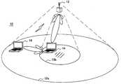
- FIG. 1is an explanatory diagram showing a configuration of a wireless communication system 10 according to a first embodiment of the present invention.
- the wireless communication system 10 shown in FIG. 1includes a first wireless communication apparatus 12 , a second wireless communication apparatus 14 , and a power receiver apparatus 16 .
- the first wireless communication apparatus 12is not limited to a wireless access point.
- the first wireless communication apparatus 12may be, for example, a network apparatus such as a router having a wireless communication function, a data processing apparatus such as a PC (Personal Computer) or workstation, or a household appliance such as a music/video player or phone.
- a network apparatussuch as a router having a wireless communication function
- a data processing apparatussuch as a PC (Personal Computer) or workstation
- a household appliancesuch as a music/video player or phone.
- PCsare shown as the second wireless communication apparatus 14 and the power receiver apparatus 16
- the second wireless communication apparatus 14 and the power receiver apparatus 16are not limited to PCs.
- These apparatusesmay be, for example, portable devices such as mobile phone terminals, personal digital assistants, or game terminals, or the aforementioned apparatuses exemplified in connection with the first wireless communication apparatus 12 .
- the first wireless communication apparatus 12can communicate with the second wireless communication apparatus 14 and the power receiver apparatus 16 , using a radio signal.
- the second wireless communication apparatus 14can also communicate with the power receiver apparatus 16 , using a radio signal.
- These wireless communicationscan be implemented by, for example, a wireless LAN that complies with IEEE802.11a,b,g,n standards.
- the first wireless communication apparatus 12can wirelessly supply power to an apparatus located therearound. Consequently, for the power receiving apparatus, even when the amount of remaining power is short, the operation thereof is kept up without performing a battery change, connection of a power supply cable, or the like.
- Wireless power supply from the first wireless communication apparatus 12is performed through, for example, an electromagnetic wave such as a microwave, ultrasound, a resonant magnetic field or electric field, or laser light.
- an electromagnetic wavesuch as a microwave, ultrasound, a resonant magnetic field or electric field, or laser light.
- a range in which power can be wirelessly suppliedis narrower than a range in which wireless communication can be performed.
- FIG. 1an area 12 a and an area 12 b are shown that are depicted as ellipses under the first wireless communication apparatus 12 .
- the area 12 arepresents a range in which wireless communication can be performed with the first wireless communication apparatus 12 . That is, both the second wireless communication apparatus 14 and the power receiver apparatus 16 within the area 12 a can perform wireless communication with the first wireless communication apparatus 12 .
- the area 12 brepresents a range in which power can be wirelessly supplied from the first wireless communication apparatus 12 . That is, while power can be supplied from the first wireless communication apparatus 12 to the second wireless communication apparatus 14 located within the area 12 b , power may not be able to be supplied from the first wireless communication apparatus 12 to the power receiver apparatus 16 located outside the area 12 b.
- the first wireless communication apparatus 12recognizes a location of the power receiver apparatus 16 and performs power supply to the power receiver apparatus 16 , using the second wireless communication apparatus 14 located near the power receiver apparatus 16 , instead of using the first wireless communication apparatus 12 itself.
- the first wireless communication apparatus 12 , the second wireless communication apparatus 14 , and the power receiver apparatus 16 according to the present embodimentwill be described in detail below with reference to FIGS. 2 to 14 .
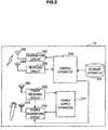
- FIG. 2is a block diagram showing an example of a hardware configuration of the first wireless communication apparatus 12 .
- the first wireless communication apparatus 12includes a control apparatus 150 , a storage apparatus 152 , a transmitting antenna 160 , a transmitting circuit 162 , a receiving antenna 164 , a receiving circuit 166 , a power transmitting antenna 170 , a power transmitting circuit 172 , and a power supply apparatus 174 .
- the control apparatus 150 of the first wireless communication apparatus 12is connected to the storage apparatus 152 , the transmitting circuit 162 , the receiving circuit 166 , and the power transmitting circuit 172 .
- a detailed hardware configuration of the control apparatus 150will be described using FIG. 3 .
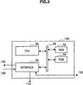
- FIG. 3is a diagram showing a detailed hardware configuration of the control apparatus 150 of the first wireless communication apparatus 12 .
- the control apparatus 150includes a CPU (Central Processing Unit) 50 , a RAM (Random Access Memory) 52 , a ROM (Read Only Memory) 54 , a bus 56 , and an interface 58 .
- CPUCentral Processing Unit
- RAMRandom Access Memory
- ROMRead Only Memory
- the CPU 50functions as an arithmetic processing apparatus and controls overall operations in the first wireless communication apparatus, according to various programs.
- the CPU 50may be a microprocessor.
- the RAM 52temporarily stores a program, data, etc., used by the CPU 50 to perform a computing process.
- the ROM 54a program that describes part or all of a process performed by the first wireless communication apparatus 12 , and the like are stored. These components are interconnected via the bus 56 .
- the interface 58is an interface for connecting the control apparatus 150 to the storage apparatus 152 , the transmitting circuit 162 , the receiving circuit 166 , and the power transmitting circuit 172 .
- data stored in the storage apparatus 152is read by the CPU 50 through the interface 58 .
- a signal generated by the CPU 50is output to the transmitting circuit 162 through the interface 58 .
- a signal demodulated and decoded by the receiving circuit 166is input to the CPU 50 through the interface 58 .
- a signal instructing, by the CPU 50 , the power transmitting circuit 172 to perform power transmissionis output to the power transmitting circuit 172 through the interface 58 .
- an input apparatus and an output apparatusmay be further connected to the CPU 50 through the interface 58 .
- the storage apparatus 152is an apparatus for storing data or programs and is configured by, for example, a hard disk drive or a flash memory.
- the transmitting antenna 160is connected to the transmitting circuit 162 and is used for transmitting a radio signal from the first wireless communication apparatus 12 .
- the transmitting circuit 162performs encoding, modulation, etc., for a transmitted signal based on an instruction from the control apparatus 150 and then outputs a radio signal from the transmitting antenna 160 .
- the receiving antenna 164is connected to the receiving circuit 166 and receives a radio signal in a predetermined frequency band.
- the receiving circuit 166performs demodulation, decoding, etc., for a signal received by the receiving antenna 164 and outputs the processed signal to the control apparatus 150 .
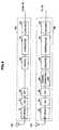
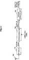
- FIG. 4is a block diagram showing an example of detailed circuit configurations of the transmitting circuit 162 and the receiving circuit 166 .
- the transmitting circuit 162has an encoder 62 , an interleaver 64 , a mapper 66 , an Inverse Fast Fourier Transformer (IFFT) 68 , a Digital-to-Analog Converter (DAC) 70 , and an RF circuit 72 .
- the receiving circuit 166has an RF circuit 82 , an Analog-to-Digital Converter (ADC) 84 , a Fast Fourier Transformer (FFT) 86 , a channel correcting unit 88 , a demapper 90 , a deinterleaver 92 , and a decoder 94 .
- ADCAnalog-to-Digital Converter
- FFTFast Fourier Transformer
- the RF circuit 72 of the transmitting circuit 162is connected to the transmitting antenna 160 and the RF circuit 82 of the receiving circuit 166 is connected to the receiving antenna 164 .
- an antenna and an antenna switchmay be provided and the antenna may be used in a shared manner by switching the switch upon transmission and reception.
- data for transmissionthat is generated as a result of a process performed in hierarchies higher than MAC (Media Access Control) is input to the encoder 62 from the control circuit 150 .
- the input transmitted datais encoded by the encoder 62 and the encoded transmitted data is interleaved by the interleaver 64 .
- the interleaved transmitted datais modulated by the mapper 66 and the modulated transmitted data is inverse-fast-Fourier-transformed by the IFFT 68 .
- An output from the IFFT 68is converted into an analog signal by the DA converter 70 and the analog signal is upconverted by the RF circuit 72 and then the upconverted signal is transmitted from the transmitting antenna 160 .
- a signal received by the receiving antenna 164is modulated by the RF circuit 82 and the modulated signal is converted into a digital signal by the AD converter 84 .
- the digital signalis fast-Fourier-transformed by the FFT 86 and the fast-Fourier-transformed digital signal is sent to the channel correcting unit 88 .
- the channel correcting unit 88performs a process of correcting a channel of the received signal.
- the signal corrected by the channel correcting unit 88is sent to the demapper 90 where the signal is demodulated.
- the demodulated signalis sent to the deinterleaver 92 .
- the deinterleaver 92performs a process of changing the interleaved received signal back to its original form.
- the received signal output from the deinterleaver 92is sent to the decoder 94 where the received signal is decoded.
- An output signal from the decoder 94is sent to the control circuit 150 .
- the power transmitting antenna 170is connected to the power transmitting circuit 172 and is used for supplying power from the first wireless communication apparatus 12 .
- the power transmitting circuit 172converts power received from the power supply apparatus 174 into energy such as an electromagnetic wave, ultrasonic, laser light, etc. based on an instruction from the control apparatus 150 , and outputs the energy from the power transmitting antenna 170 .
- the power supply apparatus 174may be, for example, a power supply apparatus or AC (Alternating Current) adapter that is connected to a commercial power supply, a battery such as a rechargeable battery or dry battery, or a power generator.
- ACAlternating Current
- FIG. 2depiction of wiring used by the components in the first wireless communication apparatus 12 to receive a power supply from the power supply apparatus 174 is omitted for ease of understanding.
- FIG. 5is a block diagram showing an example of a hardware configuration of the second wireless communication apparatus 14 .
- the second wireless communication apparatus 14includes a control apparatus 250 , a storage apparatus 252 , a transmitting antenna 260 , a transmitting circuit 262 , a receiving antenna 264 , a receiving circuit 266 , a power transmitting antenna 270 , a power transmitting circuit 272 , a power supply apparatus 274 , a power receiving antenna 280 , and a power receiving circuit 282 .
- the control apparatus 250 and the storage apparatus 252can be configured in the same manner as the aforementioned control apparatus 150 and storage apparatus 152 of the first wireless communication apparatus 12 , except for the following points.
- the transmitting antenna 260 , the transmitting circuit 262 , the receiving antenna 264 , and the receiving circuit 266can be configured in the same manner as the aforementioned transmitting antenna 160 , transmitting circuit 162 , receiving antenna 164 , and receiving circuit 166 of the first wireless communication apparatus 12 .
- the power receiving antenna 280 of the second wireless communication apparatus 14is connected to the power receiving circuit 282 and is used for receiving a power supply from the first wireless communication apparatus 12 .
- the power receiving circuit 282converts energy received in the form of an electromagnetic wave, ultrasonic, laser light, etc., using the power receiving antenna 280 , into power and accumulates the power in the power supply apparatus 274 .
- the power transmitting antenna 270 of the second wireless communication apparatus 14is connected to the power transmitting circuit 272 and is used for supplying power from the second wireless communication apparatus 14 .
- the power transmitting circuit 272converts power received from the power supply apparatus 274 into energy such as an electromagnetic wave, ultrasonic, laser light, etc., or relays energy to be passed from the power receiving circuit 282 based on an instruction from the control apparatus 250 , and outputs the energy from the power transmitting antenna 270 .
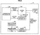
- FIG. 6is a block diagram showing an example of a hardware configuration of the power receiver apparatus 16 .
- the power receiver apparatus 16includes a control apparatus 350 , a storage apparatus 352 , an input apparatus 354 , an output apparatus 356 , a transmitting antenna 360 , a transmitting circuit 362 , a receiving antenna 364 , a receiving circuit 366 , a power supply apparatus 374 , a power receiving antenna 380 , and a power receiving circuit 382 .
- the control apparatus 350 and the storage apparatus 352can be configured in the same manner as the aforementioned control apparatus 150 and storage apparatus 152 of the first wireless communication apparatus 12 , except for the following points.
- the transmitting antenna 360 , the transmitting circuit 362 , the receiving antenna 364 , and the receiving circuit 366can be configured in the same manner as the aforementioned transmitting antenna 160 , transmitting circuit 162 , receiving antenna 164 , and receiving circuit 166 of the first wireless communication apparatus 12 .
- the input apparatus 354 and the output apparatus 356are connected to the control apparatus 350 of the power receiver apparatus 16 .
- the input apparatus 354is an apparatus for providing an instruction, etc., from a user to the power receiver apparatus 16 .
- the input apparatus 354may include, for example, a button, a switch, a lever, a mouse, or a keyboard, or an audio input apparatus.
- the output apparatus 356is an apparatus for presenting data to the user by means of an image, video, audio, etc.
- the output apparatus 356may include, for example, a display apparatus such as a CRT (Cathode Ray Tube), a liquid crystal display, or an OLED (Organic Light Emitting Diode) or an audio output apparatus such as a speaker.
- a display apparatussuch as a CRT (Cathode Ray Tube), a liquid crystal display, or an OLED (Organic Light Emitting Diode) or an audio output apparatus such as a speaker.
- the power receiving antenna 380 of the power receiver apparatus 16is connected to the power receiving circuit 382 and is used for receiving a power supply from the first wireless communication apparatus 12 or the second wireless communication apparatus 14 .
- the power receiving circuit 382converts energy received in the form of an electromagnetic wave, ultrasonic, laser light, etc., via the power receiving antenna 380 , into power and accumulates the power in the power supply apparatus 374 .
- FIGS. 2 , 5 , and 6show, as an example of a configuration for supplying power to a power-receiver-side apparatus from a power-transmitter-side apparatus, a configuration using a power transmitting antenna and a power transmitting circuit and a power receiving antenna and a power receiving circuit.
- the configuration for supplying powervaries in practice, depending on what form of energy the power is to be converted to.
- four exemplary configurations for supplying power to the power-receiver-side apparatus from the power-transmitter-side apparatuswill be described using FIGS. 19 to 22 . Note that although, in the exemplary configurations described in FIGS.
- the reference numerals used for the first wireless communication apparatus 12are provided to the power transmitter side and the reference numerals used for the second wireless communication apparatus 14 are provided to the power receiver side, each exemplary configuration can also be applied to power supply from the second wireless communication apparatus 14 to the power receiver apparatus 16 .
- FIG. 19is an explanatory diagram showing configurations of a power transmitting circuit 172 and a power receiving circuit 282 that operate using an electromagnetic induction.
- the power transmitting circuit 172 that operates using the electromagnetic inductionincludes a power supply apparatus 174 serving as an alternating-current power supply, a capacitor C 1 , and an inductor L 1 .
- the power receiving circuit 282includes an inductor L 2 , a capacitor C 2 , a capacitor C 3 , and a diode D 1 .
- the alternating currentflows through the inductor L 1 , whereby magnetic flux is produced around the inductor L 1 .
- the alternating current flowing through the inductor L 2 by the magnetic fluxis rectified by the diode D 1 and the capacitor C 3 and a resulting direct current is accumulated in a power supply apparatus 274 .
- the inductor L 1 and the inductor L 2respectively act as the power transmitting antenna 170 and the power receiving antenna 280 .
- FIG. 20is an explanatory diagram showing a configuration of a power receiving circuit 282 that operates using a radio wave reception.
- the power receiving circuit 282 that operates using the radio wave receptionincludes a power receiving antenna 280 , a resonant circuit 281 , a capacitor C 4 , a capacitor C 5 , a diode D 2 , a diode D 3 , a capacitor C 6 , and a capacitor C 7 .
- an alternating currentis supplied from the power receiving antenna 280 to the resonant circuit 281 and the resonant circuit 281 amplifies the alternating current by resonance.
- the amplified alternating currentis rectified by a rectifier circuit including the diode D 3 , the capacitor C 6 , etc., and a resulting direct current is accumulated in a power supply apparatus 274 .
- FIG. 21is an explanatory diagram showing configurations of a power transmitting circuit 172 and a power receiving circuit 282 that operate using a magnetic field resonance.
- the power transmitting circuit 172 that operates using the magnetic field resonanceincludes a capacitor C 8 and an inductor L 3
- the power receiving circuit 282includes a capacitor C 9 and an inductor L 4 .
- FIG. 22is an explanatory diagram showing configurations of a power transmitting circuit 172 and a power receiving circuit 282 that operate in using electric field resonance. As shown in FIG. 22 , the power transmitting circuit 172 and the power receiving circuit 282 that operate using the electric field resonance are configured by dielectric materials.
- the above-described magnetic field resonance type and electric field resonance typeuse a resonance principle in which, when two resonators having one unique frequency of vibrations are arranged, vibration applied to one resonator is also transmitted to the other resonator.
- Such a magnetic field resonance type and an electric field resonance typehave high transmission efficiency and thus can transmit power on the order of several kilowatts at a distance of several meters. Note, however, that since an antenna of a size proportional to a transmission distance may be requested, its application to generic systems may be difficult.
- FIG. 7is a block diagram showing logical, functional arrangement of the first wireless communication apparatus 12 according to the present embodiment.
- the first wireless communication apparatus 12includes a control unit 110 , a location data obtaining unit 112 , a power transmission control unit 114 , a storage unit 120 , a communication processing unit 130 , and a wireless power transmitting unit 140 .
- the control unit 110 , the location data obtaining unit 112 and the power transmission control unit 114are typically configured using the control apparatus 150 shown in FIG. 2 .
- the control unit 110controls a power supply to the power receiver apparatus 16 in the wireless communication system 10 based on location data of the power receiver apparatus 16 which is passed from the location data obtaining unit 112 . More specifically, for example, the control unit 110 compares the location data of the power receiver apparatus 16 with data on power provision ranges of the first wireless communication apparatus 12 and another wireless communication apparatus which is stored in advance in the storage unit 120 , to determine whether power supply to the power receiver apparatus 16 from each apparatus can be performed.
- data on a power provision range of another wireless communication apparatusmay be estimated at any point in time, using a location estimation method which will be described later using FIGS. 11 and 12 .
- data on a power provision range of another wireless communication apparatusmay be received and obtained from the another wireless communication apparatus through the communication processing unit 130 .
- control unit 110If, as a result of the determination made by the control unit 110 , power supply to the power receiver apparatus 16 can be performed, for example, from the second wireless communication apparatus 14 , then the control unit 110 generates a power supply request signal and transmits the power supply request signal to the second wireless communication apparatus 14 through the communication processing unit 130 .
- control unit 110may further output a power transmission instruction signal to the power transmission control unit 114 to supply power from the wireless power transmitting unit 140 .
- the control unit 110may determine whether to perform power supply, using one or more pieces of data including contract data, circuit data, and amount-of-remaining-power data which are transmitted from the power receiver apparatus 16 .
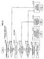
- FIG. 10is a flowchart showing, as an example, the flow of a power supply determination process in which whether to perform power supply is determined using contract data, circuit data, and amount-of-remaining-power data which are transmitted from the power receiver apparatus 16 .
- contract data of the power receiver apparatus 16is obtained (S 604 ).
- the contract data of the power receiver apparatus 16is, for example, data about a service use contract made beforehand by a user of the power receiver apparatus 16 with a power supply service provider in the wireless communication system 10 .
- the contract data of the power receiver apparatus 16may include data indicating, for example, a service use period or an amount of power to be provided.
- Such contract datais stored in advance (at the time of making a contract) in, for example, a storage unit 320 of the power receiver apparatus 16 which will be described later.
- the control unit 110 of the first wireless communication apparatus 12obtains the contract data transmitted from the power receiver apparatus 16 upon power supply.
- control unit 110determines whether content of the obtained contract data is valid (S 608 ). For example, when the transmitted contract data indicates that it is not valid because the service use period has expired, the control unit 110 determines not to perform power supply (S 632 ) and ends the process.
- circuit data of the power receiver apparatus 16is obtained (S 612 ).
- the circuit data of the power receiver apparatus 16is data indicating whether the power receiver apparatus 16 has a power receiving circuit.
- the circuit datais stored in advance in, for example, the storage unit 320 of the power receiver apparatus 16 .
- the control unit 110 of the first wireless communication apparatus 12then obtains the circuit data transmitted from the power receiver apparatus 16 upon power supply.
- control unit 110determines based on the obtained circuit data of the power receiver apparatus 16 whether the power receiver apparatus 16 has a power receiving circuit (S 616 ). If the control unit 110 determines that the power receiver apparatus 16 does not have a power receiving circuit, then the control unit 110 determines not to perform power supply (S 632 ) and ends the process.
- amount-of-remaining-power data of the power receiver apparatus 16is obtained (S 620 ).
- the amount-of-remaining-power datais, for example, data to be output from a wireless power receiving unit 342 to a control unit 310 of the power receiver apparatus 16 which will be described later.
- the amount-of-remaining-power datacan be represented by, for example, a percentage of the power supply capacity of the power receiver apparatus 16 .
- the control unit of the first wireless communication apparatus 12obtains the amount-of-remaining-power data transmitted from the power receiver apparatus 16 upon power supply.
- the control unit 110determines based on the obtained amount-of-remaining-power data of the power receiver apparatus 16 whether the amount of remaining power of the power receiver apparatus 16 is short, by, for example, making a comparison with a predetermined threshold value (S 624 ). If the control unit 110 determines that the amount of remaining power of the power receiver apparatus 16 is not short, then the control unit 110 determines not to perform power supply (S 632 ) and ends the process. On the other hand, if the control unit 110 determines that the amount of remaining power of the power receiver apparatus 16 is short, then the control unit 110 determines to perform power supply (S 628 ) and ends the process.
- the location data obtaining unit 112 of the first wireless communication apparatus 12estimates a location of the power receiver apparatus 16 using a signal received through the communication processing unit 130 and outputs location data to the control unit 110 .
- Location estimation by the location data obtaining unit of the first wireless communication apparatus 12can be performed by, for example, a distance measuring method using a correlator or an arrival direction estimation method as represented by a MUSIC (MUltiple Signal Classification) algorithm.
- the first wireless communication apparatus 12 and another wireless communication apparatusmay cooperate with each other to estimate a location of the power receiver apparatus 16 by a three-point positioning method.
- FIG. 11is a diagram showing a first exemplary configuration of the location data obtaining unit 112 , in which a location is estimated by a distance measuring method using a correlator.
- the location data obtaining unit 112has a receiving antenna 764 , an RF (Radio Frequency) circuit 772 , a cross-correlator 780 , and a distance estimating unit 790 .
- the location data obtaining unit 112may use the receiving antenna 164 and the RF circuit 72 shown in FIGS. 2 and 4 respectively as the receiving antenna 764 and the RF circuit 772 .
- a known radio signal transmitted from the power receiver apparatus 16is received by the receiving antenna 764 .
- a cross-correlation between a received signal output from the RF circuit 772 and a correlation signal held beforehand in the circuitis calculated by the cross-correlator 780 .
- the distance estimating unit 790can estimate a distance between the first wireless communication apparatus 12 and the power receiver apparatus 16 , using a time difference from a predetermined reference time until when a correlation peak of an output signal from the cross-correlator 780 is detected.
- FIG. 12is a diagram showing a second exemplary configuration of the location data obtaining unit 112 , in which a location is estimated using an arrival direction estimation method.
- the location data obtaining unit 112has n branches in parallel, each including a receiving antenna 864 - i , an RF circuit 872 - i , an ADC 874 - i , and an FFT 876 - i which are connected to each other in series (1 ⁇ i ⁇ n).
- Each of the n branchesis connected to an arrival direction estimating unit 890 .
- the arrival direction estimating unit 890estimates an arrival direction (e.g., an angle R shown in FIG. 12 ) of a radio signal from the power receiver apparatus 16 , using a phase difference and an amplitude difference between signals received by the respective branches.
- an arrival direction estimation algorithm by the arrival direction estimating unit 890the MUSIC algorithm which is commonly used by adaptive array antennas, or the like, can be used.
- the location data obtaining unit 112may use a combination of the first exemplary configuration described using FIG. 11 and the second exemplary configuration described using FIG. 12 . By doing so, the location data obtaining unit 112 can estimate a detailed location of the power receiver apparatus 16 , using the estimated distance and direction of the power receiver apparatus 16 .
- the communication processing unit 130transmits a radio signal using the transmitting antenna 160 and the transmitting circuit 162 shown in FIG. 2 , and receives a radio signal using the receiving antenna 164 and the receiving circuit 166 .
- a power supply request signalwhich will be described later is transmitted from the first wireless communication apparatus 12 to the second wireless communication apparatus 14 through the communication processing unit 130 .
- contract data, circuit data, amount-of-remaining-power data, etc., of the power receiver apparatus 16may be received from the power receiver apparatus 16 through the communication processing unit 130 .
- the power transmission control unit 114When the power transmission control unit 114 receives a power transmission instruction signal from the control unit 110 , the power transmission control unit 114 starts or stops power supply from the wireless power transmitting unit 140 .
- the storage unit 120is a storage area for storing data or programs, which is configured by the storage apparatus 152 shown in FIG. 2 , the ROM 54 shown in FIG. 3 , or the like. In the storage unit 120 , for example, the aforementioned data on power supplyable ranges of the first wireless communication apparatus 12 and another wireless communication apparatus is stored.
- the wireless power transmitting unit 140supplies power received from the power supply apparatus 174 , to the second wireless communication apparatus 14 or the power receiver apparatus 16 , using the power transmitting antenna 170 and the power transmitting circuit 172 shown in FIG. 2 . Power supply from the wireless power transmitting unit 140 is performed in response to control by the power transmission control unit 114 .
- FIG. 8is a block diagram showing logical, functional arrangement of the second wireless communication apparatus 14 according to the present embodiment.
- the second wireless communication apparatus 14includes a control unit 210 , a location data obtaining unit 212 , a power transmission control unit 214 , a storage unit 220 , a communication processing unit 230 , a wireless power transmitting unit 240 , and a wireless power receiving unit 242 .
- the control unit 210 , the location data obtaining unit 212 , and the power transmission control unit 214are typically configured using the control apparatus 250 shown in FIG. 5 .
- the control unit 210After the control unit 210 received a power supply request signal from the first wireless communication apparatus 12 through the communication processing unit 230 , the control unit 210 outputs a power transmission instruction signal to the power transmission control unit 214 based on location data to be passed from the location data obtaining unit 212 .
- the power supply request signalincludes, for example, an identifier representing an apparatus serving as a power supply destination.
- the power receiver apparatus 16corresponds to the apparatus serving as a power supply destination.
- a MAC address, an IP address, a host name, etc., of the power receiver apparatus 16can be used.
- the power supply request signalmay include the contract data, circuit data, or amount-of-remaining-power data of the power receiver apparatus 16 which is described using FIG. 10 , and the control unit 210 of the second wireless communication apparatus 14 may perform a power supply determination process. Instead of that, the control unit 210 of the second wireless communication apparatus 14 may directly receive contract data, circuit data, or amount-of-remaining-power data from the power receiver apparatus 16 through the communication processing unit 230 and perform a power supply determination process.
- the power supply request signalmay include location data of the power receiver apparatus 16 obtained by the first wireless communication apparatus 12 .
- the power supply request signalmay include a bit value indicating the start or end of power supply and when the amount of remaining power of the power receiver apparatus 16 is sufficiently recovered, the first wireless communication apparatus 12 may instruct the second wireless communication apparatus 14 to end the power supply.
- the location data obtaining unit 212 of the second wireless communication apparatus 14obtains, for example, location data of the power receiver apparatus 16 which is transmitted from the first wireless communication apparatus 12 and received through the communication processing unit 230 .
- the location data of the power receiver apparatus 16may be transmitted from the first wireless communication apparatus 12 separately from the aforementioned power supply request signal or may be transmitted as part of the power supply request signal.
- the location data obtaining unit 212outputs the obtained location data to the control unit 210 .
- the storage unit 220 and the communication processing unit 230 of the second wireless communication apparatus 14have the same functions as the storage unit 120 and the communication processing unit 130 of the first wireless communication apparatus 12 described using FIG. 7 .
- the power transmission control unit 214After the power transmission control unit 214 received a power transmission instruction signal from the control unit 210 , the power transmission control unit 214 starts or stops power supply from the wireless power transmitting unit 240 .
- the wireless power transmitting unit 240supplies power to the power receiver apparatus 16 using the power transmitting antenna 270 and the power transmitting circuit 272 shown in FIG. 5 .
- the wireless power transmitting unit 240may supply power to the power receiver apparatus 16 by converting power received from the power supply apparatus 274 into energy.
- the wireless power transmitting unit 240may supply power to the power receiver apparatus 16 by relaying energy as it is that is received by the wireless power receiving unit 242 from the first wireless communication apparatus 12 . Power supply from the wireless power transmitting unit 240 is performed in response to control by the power transmission control unit 214 .
- the wireless power transmitting unit 242converts energy received from the first wireless communication apparatus 12 using the power receiving antenna 280 and the power receiving circuit 282 shown in FIG. 5 into power and accumulates the power in the power supply apparatus 274 or relays the power to the wireless power transmitting unit 240 .
- FIG. 9is a block diagram showing logical, functional arrangement of the power receiver apparatus 16 according to the present embodiment.
- the power receiver apparatus 16includes a control unit 310 , a storage unit 320 , an input unit 322 , an output unit 324 , a communication processing unit 330 , and a wireless power receiving unit 342 .
- the control unit 310is typically configured using the control apparatus 350 shown in FIG. 6 and controls overall operations of the power receiver apparatus 16 .
- the input unit 322for example, when a user operates the input apparatus 354 shown in FIG. 6 , converts the operation into an input signal and transmits the input signal to the control unit 310 .
- the output unit 324for example, displays or outputs as audio on the output apparatus 356 shown in FIG. 6 output data such as a power reception status to be passed from the control unit 310 .
- the storage unit 320is a storage area for storing data or programs, which is configured by the storage apparatus 352 shown in FIG. 6 , a ROM in the control apparatus 350 , or the like.
- the storage unit 320stores, as described above, contract data, circuit data, etc., of the power receiver apparatus 16 .
- the function of the communication processing unit 330is the same as the function of the aforementioned communication processing unit 130 of the first wireless communication apparatus 12 .
- the wireless power receiving unit 342converts energy supplied from, for example, the second wireless communication apparatus 14 using the power receiving antenna 380 and the power receiving circuit 382 shown in FIG. 6 into power and accumulates the power in the power supply apparatus 374 . Further, the wireless power receiving unit 342 detects an amount of remaining power of the power supply apparatus 374 and outputs amount-of-remaining-power data to the control unit 310 .
- FIGS. 7 to 9The logical, functional arrangement of the first wireless communication apparatus 12 , the second wireless communication apparatus 14 , and the power receiver apparatus 16 according to the present embodiment has been described so far using FIGS. 7 to 9 .
- the flow of a power supply process according to the present embodimentwill be described using FIGS. 13 and 14 .
- FIG. 13is a flowchart showing, as an example, the flow of a power supply process performed by the first wireless communication apparatus 12 according to the present embodiment.
- a power supply determination process(the process described using FIG. 10 ) by the control unit 110 is performed (S 1104 ).
- the power supply determination process by the control unit 110can be triggered when, for example, a user of the power receiver apparatus 16 operates the input unit 322 , whereby a signal demanding power supply is transmitted to the first wireless communication apparatus 12 .
- the signal demanding power supplymay include contract data, circuit data, or amount-of-remaining-power data of the power receiver apparatus 16 which is used in the power supply determination process.
- the power receiver apparatus 16may periodically send out a signal demanding power supply, to apparatuses therearound.
- the processbranches off according to a result of the power supply determination process (S 1108 ).
- the location data obtaining unit 112estimates a location of the power receiver apparatus 16 using a radio signal received from the power receiver apparatus 16 , and thereby obtains location data.
- the location data of the power receiver apparatus 16 obtained hereis passed to the control unit 110 (S 1112 ).
- the location data in the present embodimentfor example, a distance estimation result obtained in the first exemplary configuration of the location data obtaining unit 112 shown in FIG. 11 , an arrival direction estimation result obtained in the second exemplary configuration of the location data obtaining unit 112 shown in FIG. 12 , a combination thereof, or the like, can be used.
- the control unit 110compares the location data passed from the location data obtaining unit 112 with data on a power supplyable range stored in advance in the storage unit 120 , to determine whether the power receiver apparatus 16 is located within a power supplyable range from the first wireless communication apparatus 12 (S 1116 ).
- the control unit 110then outputs a power transmission instruction signal to the power transmission control unit 114 , whereby power transmission from the wireless power transmitting unit 140 to the power receiver apparatus 16 starts (S 1136 ).
- the control unit 110further determines whether there is another apparatus that can supply power to the power receiver apparatus 16 (S 1120 ).
- the determination at S 1120may be performed such that, for example, the location data obtaining unit 112 obtains location data of another wireless communication apparatus stored in advance in the storage unit 120 and the control unit 110 compares the obtained location data with the location data of the power receiver apparatus 16 .
- the location data obtaining unit 112may estimate a location of another wireless communication apparatus by the techniques described using FIGS. 11 and 12 and the control unit 110 may receive estimated location data of the another wireless communication apparatus from the location data obtaining unit 112 and use the estimated location data for the above-described comparison.
- the control unit 110 of the first wireless communication apparatus 12transmits the aforementioned power supply request signal to the second wireless communication apparatus 14 through the communication processing unit 130 (S 1124 ).
- control unit 110 of the first wireless communication apparatus 12transmits the location data of the power receiver apparatus 16 to the second wireless communication apparatus 14 through the communication processing unit 130 (S 1128 ).
- the second wireless communication apparatus 14also has a location estimation function, as described above, a location data transmission process from the first wireless communication apparatus 12 to the second wireless communication apparatus 14 may be omitted.
- the location data of the power receiver apparatus 16may be transmitted as part of the power supply request signal.
- control unit 110 of the first wireless communication apparatus 12outputs a power transmission instruction signal to the power transmission control unit 114 , whereby power supply from the wireless power transmitting unit 140 to the second wireless communication apparatus 14 starts (S 1132 ).
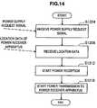
- FIG. 14is a flowchart showing the flow of a power supply process performed by the second wireless communication apparatus 14 during the process described using FIG. 13 , in which the second wireless communication apparatus 14 receives a power transmission request signal transmitted from the first wireless communication apparatus 12 and performs power supply to the power receiver apparatus 16 .
- the communication processing unit 230 of the second wireless communication apparatus 14receives a power supply request signal (S 1204 ).
- the control unit 210recognizes that the power supply target is the power receiver apparatus 16 based on, for example, an identifier included in the power supply request signal.
- the communication processing unit 230further receives location data of the power receiver apparatus 16 transmitted from the first wireless communication apparatus 12 .
- the location datais obtained by the location data obtaining unit 212 and passed to the control unit 210 (S 1208 ).
- power supply from the first wireless communication apparatus 12 to the second wireless communication apparatus 14starts (S 1212 ).
- the control unit 210 of the second wireless communication apparatus 14outputs a power transmission instruction signal to the power transmission control unit 214 , to start power supply from the wireless power transmitting unit 240 to the power receiver apparatus 16 (S 1216 ).
- the second wireless communication apparatus 14may orient the directivity of the power transmitting antenna to a power supply destination apparatus specified by the power supply request signal (which, in this example, corresponds to the power receiver apparatus 16 ) so that power is supplied only to the apparatus to which the directivity is oriented.
- the power supply request signalwhich, in this example, corresponds to the power receiver apparatus 16
- the second wireless communication apparatus 14may orient the directivity of the power transmitting antenna to a power supply destination apparatus specified by the power supply request signal (which, in this example, corresponds to the power receiver apparatus 16 ) so that power is supplied only to the apparatus to which the directivity is oriented.
- the location data obtaining unit 112 of the first wireless communication apparatus 12obtains location data of the power receiver apparatus 16 . Then, using the location data of the power receiver apparatus 16 output from the location data obtaining unit 112 , the control unit 110 determines whether the power receiver apparatus 16 is located within a power supplyable range from the first wireless communication apparatus 12 and another wireless communication apparatus.
- a power supply request signal requesting a power supply for the power receiver apparatus 16is transmitted to the second wireless communication apparatus 14 .
- the second wireless communication apparatus 14receives the power supply request signal from the first wireless communication apparatus 12
- the second wireless communication apparatus 14lets the wireless power transmitting unit 240 supply power to the power receiver apparatus 16 .
- the control unit 110 of the first wireless communication apparatus 12transmits location data obtained by the location data obtaining unit 112 to the second wireless communication apparatus 14 .
- the location data of the power receiver apparatus 16 which is already obtained by the first wireless communication apparatus 12can be shared.
- the control unit 110when the second wireless communication apparatus 14 is within the power supplyable range from the first wireless communication apparatus 12 , the control unit 110 lets the wireless power transmitting unit 140 supply power to the wireless power receiving unit 242 of the second wireless communication apparatus 14 .
- the control unit 210 of the second wireless communication apparatus 14lets the wireless power receiving unit 242 receive the power supply from the first wireless communication apparatus 12 and lets the wireless power transmitting unit 240 supply power to the power receiver apparatus 16 .
- the second wireless communication apparatus 14can relay and supply power held by the first wireless communication apparatus 12 to the power receiver apparatus 16 .
- the functions of the first wireless communication apparatus 12 , the second wireless communication apparatus 14 , and the power receiver apparatus 16 according to the first embodimentmay be implemented as a computer program.
- the programis, for example, stored in the storage unit 120 and loaded into the RAM 52 and then executed by the CPU 50 .
- FIGS. 15 to 18Next, a second embodiment of the present invention will be described using FIGS. 15 to 18 .
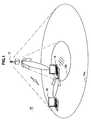
- FIG. 15is an explanatory diagram showing a configuration of a wireless communication system 20 according to the second embodiment of the present invention.
- the wireless communication system 20 shown in FIG. 15includes a first wireless communication apparatus 12 , a second wireless communication apparatus 24 , and a power receiver apparatus 16 .
- a wireless access pointis shown as the second wireless communication apparatus 24
- the second wireless communication apparatus 24is not limited to a wireless access point.
- the second wireless communication apparatus 24may be, for example, a network apparatus, a data processing apparatus, or a household appliance which is exemplified in connection with the first wireless communication apparatus 12 in the description of FIG. 1 .
- an area 24 bis shown around the second wireless communication apparatus 24 .
- the area 24 brepresents a range in which power can be wirelessly supplied from the second wireless communication apparatus 24 . That is, power can be supplied to the power receiver apparatus 16 located within the areas 12 b and 24 b , from the first wireless communication apparatus 12 and the second wireless communication apparatus 24 .
- the first wireless communication apparatus 12recognizes a location of the power receiver apparatus 16 and power supply is performed parallel to the power receiver apparatus 16 from the second wireless communication apparatus 24 located near the power receiver apparatus 16 and the first wireless communication apparatus 12 .
- the second wireless communication apparatus 24can be configured in the same manner as the hardware configuration of the first wireless communication apparatus 12 described using FIG. 2 . That is, in the present embodiment, the second wireless communication apparatus 24 may not need to include a receiving antenna and a receiving circuit.
- FIG. 16is a block diagram showing logical, functional arrangement of the second wireless communication apparatus 24 .
- the second wireless communication apparatus 24has all functions of the second wireless communication apparatus 14 according to the first embodiment, except the function of the wireless power receiving unit 242 .
- a location data obtaining unit 212 of the second wireless communication apparatus 24estimates a location of the power receiver apparatus 16 using a radio signal received from the power receiver apparatus 16 , and outputs location data to a control unit 210 .
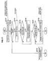
- FIG. 17is a flowchart showing, as an example, the flow of a power supply process performed by the first wireless communication apparatus 12 according to the present embodiment.
- a power supply determination process(the process described using FIG. 10 ) by a control unit 110 is performed (S 2104 ).
- the power supply determination process by the control unit 110can be triggered when, for example, a power supply demand signal including contract data, circuit data, or amount-of-remaining-power data from the power receiver apparatus 16 is received. Thereafter, the process branches off according to a result of the power supply determination process (S 2108 ).
- the location data obtaining unit 212estimates a location of the power receiver apparatus 16 using a radio signal received from the power receiver apparatus 16 , and thereby obtains location data.
- the location data of the power receiver apparatus 16 obtained hereis passed to the control unit 110 (S 2112 ).
- the control unit 110determines based on the passed location data of the power receiver apparatus 16 whether the power receiver apparatus 16 is located within a power supplyable range from the first wireless communication apparatus 12 (S 2116 ). If it is determined that the power receiver apparatus 16 is located within a power supplyable range from the first wireless communication apparatus 12 , then the control unit 110 outputs a power transmission instruction signal to a power transmission control unit 114 , whereby power transmission from a wireless power transmitting unit 140 to the power receiver apparatus 16 starts (S 2120 ). Thereafter, the control unit 110 determines whether the power receiver apparatus 16 is located within a power supplyable range from another wireless communication apparatus (S 2124 ).
- the control unit 110does not perform power transmission from the first wireless communication apparatus 12 but moves to a determination as to whether the power receiver apparatus 16 is located within a power supplyable range from another wireless communication apparatus (S 2124 ).
- the determination at S 2124may be performed such that, for example, a location data obtaining unit 112 obtains location data of another wireless communication apparatus stored in advance in a storage unit 120 and the control unit 110 compares the obtained location data with the location data of the power receiver apparatus 16 .
- the location data obtaining unit 112may estimate a location of another wireless communication apparatus using the techniques described in connection with FIGS. 11 and 12 for estimating a location of a source apparatus of a radio signal.
- the control unit 110transmits a power supply request signal to the second wireless communication apparatus 24 through a communication processing unit 130 (S 2128 ).
- the control unit 110 of the first wireless communication apparatus 12may transmit a power supply request signal to each of a plurality of other wireless communication apparatuses that can supply power to the power receiver apparatus 16 .
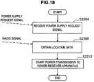
- FIG. 18is a flowchart showing the flow of a power supply process performed by the second wireless communication apparatus 24 during the process described using FIG. 17 , in which the second wireless communication apparatus 24 receives a power transmission request signal transmitted from the first wireless communication apparatus 12 and performs power supply to the power receiver apparatus 16 .
- a communication processing unit 230 of the second wireless communication apparatus 24receives a power supply request signal transmitted from the first wireless communication apparatus 12 (S 2204 ).
- the control unit 210recognizes that the power supply target is the power receiver apparatus 16 based on data included in the power supply request signal.
- the location data obtaining unit 212 of the second wireless communication apparatus 24estimates a location of the power receiver apparatus 16 using a radio signal received from the power receiver apparatus 16 , and thereby obtains location data.
- the location data of the power receiver apparatus 16 obtained hereis passed to the control unit 210 (S 2208 ).
- control unit 210 of the second wireless communication apparatus 24outputs a power transmission instruction signal to a power transmission control unit 214 , to start power supply from a wireless power transmitting unit 240 to the power receiver apparatus 16 (S 2212 ).
- the location data obtaining unit 112 of the first wireless communication apparatus 12obtains location data of the power receiver apparatus 16 . Then, using the location data of the power receiver apparatus 16 , the control unit 110 of the first wireless communication apparatus 12 determines whether the power receiver apparatus 16 is located within a power supplyable range from another wireless communication apparatus. Herein, when, for example, it is determined that the power receiver apparatus 16 is located within a power supplyable range from the second wireless communication apparatus 24 , the first wireless communication apparatus 12 transmits a power supply request signal to the second wireless communication apparatus 24 . Then, after the second wireless communication apparatus 24 received the power supply request signal from the first wireless communication apparatus 12 , the second wireless communication apparatus 24 lets the wireless power transmitting unit 240 supply power to the power receiver apparatus 16 .
- control unit 110 of the first wireless communication apparatus 12determines that the power receiver apparatus 16 is within a power supplyable range from the first wireless communication apparatus 12 .
- the control unit 110further lets the wireless power transmitting unit 140 supply power to the power receiver apparatus 16 .
- the location data obtaining unit 212 of the second wireless communication apparatus 24estimates location data of the power receiver apparatus 16 , using a radio signal received from the power receiver apparatus 16 through the communication processing unit 230 .
- the second wireless communication apparatus 24can recognize location data of the power receiver apparatus 16 and perform, for example, directivity control of a power transmitting antenna which is described above in connection with the first embodiment.
- the first wireless communication apparatus 12determines whether the power receiver apparatus 16 is located within a power supplyable range, using data on a power supplyable range stored in advance in the storage unit 120 .
- the data on a power supplyable range used hereis represented by, for example, the value of a power supplyable distance from the first wireless communication apparatus 12 .
- Such datais typically grasped beforehand through an experiment where power supply is actually performed, or the like, and converted into numbers and the resulting numerical value is held in the storage unit 120 .
- the data on a power supplyable rangemay be dynamically updated. Dynamic update to the data on a power supplyable range can be performed by each terminal reporting a power reception status periodically or at any point in time to the first wireless communication apparatus 12 , using a wireless communication function.
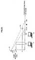
- FIG. 23is a schematic diagram showing an example of a process of dynamically updating data on a power supplyable range.
- a first wireless communication apparatus 12first stores in advance a power supplyable range 12 b figured out through an experiment.
- the power supplyable range 12 bindicates a distance of 2 [m] from the first wireless communication apparatus 12 . It is assumed that thereafter power supply to two power receiver terminals 17 and 18 located within the power supplyable range 12 b starts and the first wireless communication apparatus 12 receives reports about power reception statuses from the respective terminals.
- the power reception status reported from the power receiver terminal 17indicates distance D 1 and power reception level Lv 2 .
- the power reception status reported from the power receiver terminal 18indicates distance D 2 and power reception level Lv 1 .
- the first wireless communication apparatus 12determines a distance at which the power reception level becomes zero, according to an attenuation model of the power reception level.
- the first wireless communication apparatus 12calculates based on the power reception statuses reported from the power receiver terminals 17 and 18 , a current power supplyable range 12 c to be a distance of 1.5 [m], according to a linear model and dynamically updates the data on a power supplyable range (the arrow in the drawing).
- the attenuation model of the power reception leveldepends on the power supply schemes described using FIGS. 19 to 22 .
- the attenuation model of the power reception levelis not limited to the linear model shown in FIG. 23 and may be, for example, a model in which the power reception level and the distance are inversely proportional to each other.
- a received-power value converted to powerthe strength of a magnetic field or the intensity of received laser light, according to a power supply scheme, or the like, may be used.
- Part or all of the functions of the first wireless communication apparatus 12 , the second wireless communication apparatus 24 , and the power receiver apparatus 16 according to the second embodimentmay be implemented as a computer program.
- the programis, for example, stored in a storage unit 220 and loaded into a RAM of the control unit 210 and then executed by a CPU.
- steps of power supply processes according to the first and second embodimentsmay not necessarily need to be performed in the order described in the flowcharts.
- Each step performed by the first wireless communication apparatus 12 and the second wireless communication apparatuses 14 and 24may include operations to be performed parallel or individually.
- the functional blocks of the first wireless communication apparatus 12 and the second wireless communication apparatuses 14 and 24 shown in FIGS. 7 , 8 , and 16can be configured by hardware and a series of processing operations can be implemented by hardware logic.
Landscapes
- Engineering & Computer Science (AREA)
- Computer Networks & Wireless Communication (AREA)
- Power Engineering (AREA)
- Signal Processing (AREA)
- Charge And Discharge Circuits For Batteries Or The Like (AREA)
Abstract
Description
Claims (23)
Applications Claiming Priority (2)
| Application Number | Priority Date | Filing Date | Title |
|---|---|---|---|
| JP2008108135AJP4661900B2 (en) | 2008-04-17 | 2008-04-17 | Wireless communication apparatus, power supply method, program, and wireless communication system |
| JPP2008-108135 | 2008-04-17 |
Publications (2)
| Publication Number | Publication Date |
|---|---|
| US20090264069A1 US20090264069A1 (en) | 2009-10-22 |
| US8180286B2true US8180286B2 (en) | 2012-05-15 |
Family
ID=41201503
Family Applications (1)
| Application Number | Title | Priority Date | Filing Date |
|---|---|---|---|
| US12/425,140Expired - Fee RelatedUS8180286B2 (en) | 2008-04-17 | 2009-04-16 | Wireless power and communication system |
Country Status (2)
| Country | Link |
|---|---|
| US (1) | US8180286B2 (en) |
| JP (1) | JP4661900B2 (en) |
Cited By (214)
| Publication number | Priority date | Publication date | Assignee | Title |
|---|---|---|---|---|
| US20120155558A1 (en)* | 2010-12-20 | 2012-06-21 | Nai-Chien Chang | Integrating device of wireless charging and wireless network function |
| US20130030892A1 (en)* | 2011-07-25 | 2013-01-31 | Xun Liu | System and method for operating a mobile device |
| US20150091508A1 (en)* | 2013-10-01 | 2015-04-02 | Blackberry Limited | Bi-directional communication with a device under charge |
| US9124125B2 (en) | 2013-05-10 | 2015-09-01 | Energous Corporation | Wireless power transmission with selective range |
| US9130397B2 (en) | 2013-05-10 | 2015-09-08 | Energous Corporation | Wireless charging and powering of electronic devices in a vehicle |
| US9143000B2 (en) | 2012-07-06 | 2015-09-22 | Energous Corporation | Portable wireless charging pad |
| US20150326068A1 (en)* | 2014-05-07 | 2015-11-12 | Energous Corporation | Systems and methods for wireless transmission of power |
| US9252628B2 (en) | 2013-05-10 | 2016-02-02 | Energous Corporation | Laptop computer as a transmitter for wireless charging |
| US20160164301A1 (en)* | 2014-12-08 | 2016-06-09 | Disney Enterprises, Inc. | Resonant cavity mode enabled wireless power transfer |
| US9368020B1 (en)* | 2013-05-10 | 2016-06-14 | Energous Corporation | Off-premises alert system and method for wireless power receivers in a wireless power network |
| US9419443B2 (en) | 2013-05-10 | 2016-08-16 | Energous Corporation | Transducer sound arrangement for pocket-forming |
| US20160254695A1 (en)* | 2010-04-06 | 2016-09-01 | Samsung Electronics Co., Ltd. | Robot cleaning system and control method having wireless electric power charge function |
| US9438045B1 (en) | 2013-05-10 | 2016-09-06 | Energous Corporation | Methods and systems for maximum power point transfer in receivers |
| US9450449B1 (en) | 2012-07-06 | 2016-09-20 | Energous Corporation | Antenna arrangement for pocket-forming |
| US9521926B1 (en) | 2013-06-24 | 2016-12-20 | Energous Corporation | Wireless electrical temperature regulator for food and beverages |
| US9538382B2 (en) | 2013-05-10 | 2017-01-03 | Energous Corporation | System and method for smart registration of wireless power receivers in a wireless power network |
| US9537357B2 (en) | 2013-05-10 | 2017-01-03 | Energous Corporation | Wireless sound charging methods and systems for game controllers, based on pocket-forming |
| US9787103B1 (en) | 2013-08-06 | 2017-10-10 | Energous Corporation | Systems and methods for wirelessly delivering power to electronic devices that are unable to communicate with a transmitter |
| US9793758B2 (en) | 2014-05-23 | 2017-10-17 | Energous Corporation | Enhanced transmitter using frequency control for wireless power transmission |
| US9800172B1 (en) | 2014-05-07 | 2017-10-24 | Energous Corporation | Integrated rectifier and boost converter for boosting voltage received from wireless power transmission waves |
| US9806564B2 (en) | 2014-05-07 | 2017-10-31 | Energous Corporation | Integrated rectifier and boost converter for wireless power transmission |
| US9812890B1 (en) | 2013-07-11 | 2017-11-07 | Energous Corporation | Portable wireless charging pad |
| US9819230B2 (en) | 2014-05-07 | 2017-11-14 | Energous Corporation | Enhanced receiver for wireless power transmission |
| US9824815B2 (en) | 2013-05-10 | 2017-11-21 | Energous Corporation | Wireless charging and powering of healthcare gadgets and sensors |
| US9825674B1 (en) | 2014-05-23 | 2017-11-21 | Energous Corporation | Enhanced transmitter that selects configurations of antenna elements for performing wireless power transmission and receiving functions |
| US9831718B2 (en) | 2013-07-25 | 2017-11-28 | Energous Corporation | TV with integrated wireless power transmitter |
| US9838083B2 (en) | 2014-07-21 | 2017-12-05 | Energous Corporation | Systems and methods for communication with remote management systems |
| US9843201B1 (en) | 2012-07-06 | 2017-12-12 | Energous Corporation | Wireless power transmitter that selects antenna sets for transmitting wireless power to a receiver based on location of the receiver, and methods of use thereof |
| US9843763B2 (en) | 2013-05-10 | 2017-12-12 | Energous Corporation | TV system with wireless power transmitter |
| US9843213B2 (en) | 2013-08-06 | 2017-12-12 | Energous Corporation | Social power sharing for mobile devices based on pocket-forming |
| US9847677B1 (en) | 2013-10-10 | 2017-12-19 | Energous Corporation | Wireless charging and powering of healthcare gadgets and sensors |
| US9847679B2 (en) | 2014-05-07 | 2017-12-19 | Energous Corporation | System and method for controlling communication between wireless power transmitter managers |
| US9853458B1 (en) | 2014-05-07 | 2017-12-26 | Energous Corporation | Systems and methods for device and power receiver pairing |
| US9853692B1 (en) | 2014-05-23 | 2017-12-26 | Energous Corporation | Systems and methods for wireless power transmission |
| US9853485B2 (en) | 2015-10-28 | 2017-12-26 | Energous Corporation | Antenna for wireless charging systems |
| US9859797B1 (en) | 2014-05-07 | 2018-01-02 | Energous Corporation | Synchronous rectifier design for wireless power receiver |
| US9859756B2 (en) | 2012-07-06 | 2018-01-02 | Energous Corporation | Transmittersand methods for adjusting wireless power transmission based on information from receivers |
| US9859757B1 (en) | 2013-07-25 | 2018-01-02 | Energous Corporation | Antenna tile arrangements in electronic device enclosures |
| US9867062B1 (en) | 2014-07-21 | 2018-01-09 | Energous Corporation | System and methods for using a remote server to authorize a receiving device that has requested wireless power and to determine whether another receiving device should request wireless power in a wireless power transmission system |
| US9866279B2 (en) | 2013-05-10 | 2018-01-09 | Energous Corporation | Systems and methods for selecting which power transmitter should deliver wireless power to a receiving device in a wireless power delivery network |
| US9871398B1 (en) | 2013-07-01 | 2018-01-16 | Energous Corporation | Hybrid charging method for wireless power transmission based on pocket-forming |
| US9871301B2 (en) | 2014-07-21 | 2018-01-16 | Energous Corporation | Integrated miniature PIFA with artificial magnetic conductor metamaterials |
| US9871387B1 (en) | 2015-09-16 | 2018-01-16 | Energous Corporation | Systems and methods of object detection using one or more video cameras in wireless power charging systems |
| US9876536B1 (en) | 2014-05-23 | 2018-01-23 | Energous Corporation | Systems and methods for assigning groups of antennas to transmit wireless power to different wireless power receivers |
| US9876394B1 (en) | 2014-05-07 | 2018-01-23 | Energous Corporation | Boost-charger-boost system for enhanced power delivery |
| US9876648B2 (en) | 2014-08-21 | 2018-01-23 | Energous Corporation | System and method to control a wireless power transmission system by configuration of wireless power transmission control parameters |
| US9876380B1 (en) | 2013-09-13 | 2018-01-23 | Energous Corporation | Secured wireless power distribution system |
| US9876379B1 (en) | 2013-07-11 | 2018-01-23 | Energous Corporation | Wireless charging and powering of electronic devices in a vehicle |
| US9882427B2 (en) | 2013-05-10 | 2018-01-30 | Energous Corporation | Wireless power delivery using a base station to control operations of a plurality of wireless power transmitters |
| US9882395B1 (en) | 2014-05-07 | 2018-01-30 | Energous Corporation | Cluster management of transmitters in a wireless power transmission system |
| US9887739B2 (en) | 2012-07-06 | 2018-02-06 | Energous Corporation | Systems and methods for wireless power transmission by comparing voltage levels associated with power waves transmitted by antennas of a plurality of antennas of a transmitter to determine appropriate phase adjustments for the power waves |
| US9887584B1 (en) | 2014-08-21 | 2018-02-06 | Energous Corporation | Systems and methods for a configuration web service to provide configuration of a wireless power transmitter within a wireless power transmission system |
| US9893555B1 (en) | 2013-10-10 | 2018-02-13 | Energous Corporation | Wireless charging of tools using a toolbox transmitter |
| US9893535B2 (en) | 2015-02-13 | 2018-02-13 | Energous Corporation | Systems and methods for determining optimal charging positions to maximize efficiency of power received from wirelessly delivered sound wave energy |
| US9891669B2 (en) | 2014-08-21 | 2018-02-13 | Energous Corporation | Systems and methods for a configuration web service to provide configuration of a wireless power transmitter within a wireless power transmission system |
| US9893538B1 (en) | 2015-09-16 | 2018-02-13 | Energous Corporation | Systems and methods of object detection in wireless power charging systems |
| US9893768B2 (en) | 2012-07-06 | 2018-02-13 | Energous Corporation | Methodology for multiple pocket-forming |
| US9893554B2 (en) | 2014-07-14 | 2018-02-13 | Energous Corporation | System and method for providing health safety in a wireless power transmission system |
| US9899861B1 (en) | 2013-10-10 | 2018-02-20 | Energous Corporation | Wireless charging methods and systems for game controllers, based on pocket-forming |
| US9899744B1 (en) | 2015-10-28 | 2018-02-20 | Energous Corporation | Antenna for wireless charging systems |
| US9900057B2 (en) | 2012-07-06 | 2018-02-20 | Energous Corporation | Systems and methods for assigning groups of antenas of a wireless power transmitter to different wireless power receivers, and determining effective phases to use for wirelessly transmitting power using the assigned groups of antennas |
| US9899873B2 (en) | 2014-05-23 | 2018-02-20 | Energous Corporation | System and method for generating a power receiver identifier in a wireless power network |
| US9906275B2 (en) | 2015-09-15 | 2018-02-27 | Energous Corporation | Identifying receivers in a wireless charging transmission field |
| US9906065B2 (en) | 2012-07-06 | 2018-02-27 | Energous Corporation | Systems and methods of transmitting power transmission waves based on signals received at first and second subsets of a transmitter's antenna array |
| US9912199B2 (en) | 2012-07-06 | 2018-03-06 | Energous Corporation | Receivers for wireless power transmission |
| US9917477B1 (en)* | 2014-08-21 | 2018-03-13 | Energous Corporation | Systems and methods for automatically testing the communication between power transmitter and wireless receiver |
| US9923386B1 (en) | 2012-07-06 | 2018-03-20 | Energous Corporation | Systems and methods for wireless power transmission by modifying a number of antenna elements used to transmit power waves to a receiver |
| US9935482B1 (en) | 2014-02-06 | 2018-04-03 | Energous Corporation | Wireless power transmitters that transmit at determined times based on power availability and consumption at a receiving mobile device |
| US9939864B1 (en) | 2014-08-21 | 2018-04-10 | Energous Corporation | System and method to control a wireless power transmission system by configuration of wireless power transmission control parameters |
| US9941707B1 (en) | 2013-07-19 | 2018-04-10 | Energous Corporation | Home base station for multiple room coverage with multiple transmitters |
| US9941752B2 (en) | 2015-09-16 | 2018-04-10 | Energous Corporation | Systems and methods of object detection in wireless power charging systems |
| US9941747B2 (en) | 2014-07-14 | 2018-04-10 | Energous Corporation | System and method for manually selecting and deselecting devices to charge in a wireless power network |
| US9941754B2 (en) | 2012-07-06 | 2018-04-10 | Energous Corporation | Wireless power transmission with selective range |
| US9948135B2 (en) | 2015-09-22 | 2018-04-17 | Energous Corporation | Systems and methods for identifying sensitive objects in a wireless charging transmission field |
| US9954374B1 (en) | 2014-05-23 | 2018-04-24 | Energous Corporation | System and method for self-system analysis for detecting a fault in a wireless power transmission Network |
| US9966765B1 (en)* | 2013-06-25 | 2018-05-08 | Energous Corporation | Multi-mode transmitter |
| US9965009B1 (en) | 2014-08-21 | 2018-05-08 | Energous Corporation | Systems and methods for assigning a power receiver to individual power transmitters based on location of the power receiver |
| US9966784B2 (en) | 2014-06-03 | 2018-05-08 | Energous Corporation | Systems and methods for extending battery life of portable electronic devices charged by sound |
| US9973008B1 (en) | 2014-05-07 | 2018-05-15 | Energous Corporation | Wireless power receiver with boost converters directly coupled to a storage element |
| US9973021B2 (en) | 2012-07-06 | 2018-05-15 | Energous Corporation | Receivers for wireless power transmission |
| US9979440B1 (en)* | 2013-07-25 | 2018-05-22 | Energous Corporation | Antenna tile arrangements configured to operate as one functional unit |
| US9991741B1 (en) | 2014-07-14 | 2018-06-05 | Energous Corporation | System for tracking and reporting status and usage information in a wireless power management system |
| US10003211B1 (en) | 2013-06-17 | 2018-06-19 | Energous Corporation | Battery life of portable electronic devices |
| US20180175672A1 (en)* | 2016-12-19 | 2018-06-21 | Koji Yoden | Smart wireless power transfer between devices |
| US10008875B1 (en) | 2015-09-16 | 2018-06-26 | Energous Corporation | Wireless power transmitter configured to transmit power waves to a predicted location of a moving wireless power receiver |
| US10008889B2 (en) | 2014-08-21 | 2018-06-26 | Energous Corporation | Method for automatically testing the operational status of a wireless power receiver in a wireless power transmission system |
| US10008886B2 (en) | 2015-12-29 | 2018-06-26 | Energous Corporation | Modular antennas with heat sinks in wireless power transmission systems |
| US10020678B1 (en) | 2015-09-22 | 2018-07-10 | Energous Corporation | Systems and methods for selecting antennas to generate and transmit power transmission waves |
| US10021523B2 (en) | 2013-07-11 | 2018-07-10 | Energous Corporation | Proximity transmitters for wireless power charging systems |
| US10027168B2 (en) | 2015-09-22 | 2018-07-17 | Energous Corporation | Systems and methods for generating and transmitting wireless power transmission waves using antennas having a spacing that is selected by the transmitter |
| US10027180B1 (en) | 2015-11-02 | 2018-07-17 | Energous Corporation | 3D triple linear antenna that acts as heat sink |
| US10027159B2 (en) | 2015-12-24 | 2018-07-17 | Energous Corporation | Antenna for transmitting wireless power signals |
| US10027158B2 (en) | 2015-12-24 | 2018-07-17 | Energous Corporation | Near field transmitters for wireless power charging of an electronic device by leaking RF energy through an aperture |
| US10033222B1 (en) | 2015-09-22 | 2018-07-24 | Energous Corporation | Systems and methods for determining and generating a waveform for wireless power transmission waves |
| US10038337B1 (en) | 2013-09-16 | 2018-07-31 | Energous Corporation | Wireless power supply for rescue devices |
| US10038332B1 (en) | 2015-12-24 | 2018-07-31 | Energous Corporation | Systems and methods of wireless power charging through multiple receiving devices |
| US10050470B1 (en) | 2015-09-22 | 2018-08-14 | Energous Corporation | Wireless power transmission device having antennas oriented in three dimensions |
| US10050462B1 (en) | 2013-08-06 | 2018-08-14 | Energous Corporation | Social power sharing for mobile devices based on pocket-forming |
| US10063105B2 (en) | 2013-07-11 | 2018-08-28 | Energous Corporation | Proximity transmitters for wireless power charging systems |
| US10063064B1 (en) | 2014-05-23 | 2018-08-28 | Energous Corporation | System and method for generating a power receiver identifier in a wireless power network |
| US10063108B1 (en) | 2015-11-02 | 2018-08-28 | Energous Corporation | Stamped three-dimensional antenna |
| US10063106B2 (en) | 2014-05-23 | 2018-08-28 | Energous Corporation | System and method for a self-system analysis in a wireless power transmission network |
| US10068703B1 (en) | 2014-07-21 | 2018-09-04 | Energous Corporation | Integrated miniature PIFA with artificial magnetic conductor metamaterials |
| US10075008B1 (en) | 2014-07-14 | 2018-09-11 | Energous Corporation | Systems and methods for manually adjusting when receiving electronic devices are scheduled to receive wirelessly delivered power from a wireless power transmitter in a wireless power network |
| US10075017B2 (en) | 2014-02-06 | 2018-09-11 | Energous Corporation | External or internal wireless power receiver with spaced-apart antenna elements for charging or powering mobile devices using wirelessly delivered power |
| US10079515B2 (en) | 2016-12-12 | 2018-09-18 | Energous Corporation | Near-field RF charging pad with multi-band antenna element with adaptive loading to efficiently charge an electronic device at any position on the pad |
| US10090699B1 (en) | 2013-11-01 | 2018-10-02 | Energous Corporation | Wireless powered house |
| US10090886B1 (en) | 2014-07-14 | 2018-10-02 | Energous Corporation | System and method for enabling automatic charging schedules in a wireless power network to one or more devices |
| US10103552B1 (en) | 2013-06-03 | 2018-10-16 | Energous Corporation | Protocols for authenticated wireless power transmission |
| US10103582B2 (en) | 2012-07-06 | 2018-10-16 | Energous Corporation | Transmitters for wireless power transmission |
| US10116170B1 (en) | 2014-05-07 | 2018-10-30 | Energous Corporation | Methods and systems for maximum power point transfer in receivers |
| US10116143B1 (en) | 2014-07-21 | 2018-10-30 | Energous Corporation | Integrated antenna arrays for wireless power transmission |
| US10122415B2 (en) | 2014-12-27 | 2018-11-06 | Energous Corporation | Systems and methods for assigning a set of antennas of a wireless power transmitter to a wireless power receiver based on a location of the wireless power receiver |
| US10122219B1 (en) | 2017-10-10 | 2018-11-06 | Energous Corporation | Systems, methods, and devices for using a battery as a antenna for receiving wirelessly delivered power from radio frequency power waves |
| US10128686B1 (en) | 2015-09-22 | 2018-11-13 | Energous Corporation | Systems and methods for identifying receiver locations using sensor technologies |
| US10124754B1 (en) | 2013-07-19 | 2018-11-13 | Energous Corporation | Wireless charging and powering of electronic sensors in a vehicle |
| US10128693B2 (en) | 2014-07-14 | 2018-11-13 | Energous Corporation | System and method for providing health safety in a wireless power transmission system |
| US10128695B2 (en) | 2013-05-10 | 2018-11-13 | Energous Corporation | Hybrid Wi-Fi and power router transmitter |
| US10128699B2 (en) | 2014-07-14 | 2018-11-13 | Energous Corporation | Systems and methods of providing wireless power using receiver device sensor inputs |
| US10135295B2 (en) | 2015-09-22 | 2018-11-20 | Energous Corporation | Systems and methods for nullifying energy levels for wireless power transmission waves |
| US10135112B1 (en) | 2015-11-02 | 2018-11-20 | Energous Corporation | 3D antenna mount |
| US10135294B1 (en) | 2015-09-22 | 2018-11-20 | Energous Corporation | Systems and methods for preconfiguring transmission devices for power wave transmissions based on location data of one or more receivers |
| US10141768B2 (en) | 2013-06-03 | 2018-11-27 | Energous Corporation | Systems and methods for maximizing wireless power transfer efficiency by instructing a user to change a receiver device's position |
| US10148097B1 (en) | 2013-11-08 | 2018-12-04 | Energous Corporation | Systems and methods for using a predetermined number of communication channels of a wireless power transmitter to communicate with different wireless power receivers |
| US10153645B1 (en) | 2014-05-07 | 2018-12-11 | Energous Corporation | Systems and methods for designating a master power transmitter in a cluster of wireless power transmitters |
| US10153660B1 (en) | 2015-09-22 | 2018-12-11 | Energous Corporation | Systems and methods for preconfiguring sensor data for wireless charging systems |
| US10153653B1 (en) | 2014-05-07 | 2018-12-11 | Energous Corporation | Systems and methods for using application programming interfaces to control communications between a transmitter and a receiver |
| US10158259B1 (en) | 2015-09-16 | 2018-12-18 | Energous Corporation | Systems and methods for identifying receivers in a transmission field by transmitting exploratory power waves towards different segments of a transmission field |
| US10158257B2 (en) | 2014-05-01 | 2018-12-18 | Energous Corporation | System and methods for using sound waves to wirelessly deliver power to electronic devices |
| US10170917B1 (en) | 2014-05-07 | 2019-01-01 | Energous Corporation | Systems and methods for managing and controlling a wireless power network by establishing time intervals during which receivers communicate with a transmitter |
| US10186893B2 (en) | 2015-09-16 | 2019-01-22 | Energous Corporation | Systems and methods for real time or near real time wireless communications between a wireless power transmitter and a wireless power receiver |
| US10186913B2 (en) | 2012-07-06 | 2019-01-22 | Energous Corporation | System and methods for pocket-forming based on constructive and destructive interferences to power one or more wireless power receivers using a wireless power transmitter including a plurality of antennas |
| US10193396B1 (en) | 2014-05-07 | 2019-01-29 | Energous Corporation | Cluster management of transmitters in a wireless power transmission system |
| US10199849B1 (en) | 2014-08-21 | 2019-02-05 | Energous Corporation | Method for automatically testing the operational status of a wireless power receiver in a wireless power transmission system |
| US10199850B2 (en) | 2015-09-16 | 2019-02-05 | Energous Corporation | Systems and methods for wirelessly transmitting power from a transmitter to a receiver by determining refined locations of the receiver in a segmented transmission field associated with the transmitter |
| US10199835B2 (en) | 2015-12-29 | 2019-02-05 | Energous Corporation | Radar motion detection using stepped frequency in wireless power transmission system |
| US10206185B2 (en) | 2013-05-10 | 2019-02-12 | Energous Corporation | System and methods for wireless power transmission to an electronic device in accordance with user-defined restrictions |
| US10205239B1 (en) | 2014-05-07 | 2019-02-12 | Energous Corporation | Compact PIFA antenna |
| US10211680B2 (en) | 2013-07-19 | 2019-02-19 | Energous Corporation | Method for 3 dimensional pocket-forming |
| US10211685B2 (en) | 2015-09-16 | 2019-02-19 | Energous Corporation | Systems and methods for real or near real time wireless communications between a wireless power transmitter and a wireless power receiver |
| US10211682B2 (en) | 2014-05-07 | 2019-02-19 | Energous Corporation | Systems and methods for controlling operation of a transmitter of a wireless power network based on user instructions received from an authenticated computing device powered or charged by a receiver of the wireless power network |
| US10211674B1 (en) | 2013-06-12 | 2019-02-19 | Energous Corporation | Wireless charging using selected reflectors |
| US10218227B2 (en) | 2014-05-07 | 2019-02-26 | Energous Corporation | Compact PIFA antenna |
| US10224982B1 (en) | 2013-07-11 | 2019-03-05 | Energous Corporation | Wireless power transmitters for transmitting wireless power and tracking whether wireless power receivers are within authorized locations |
| US10224758B2 (en) | 2013-05-10 | 2019-03-05 | Energous Corporation | Wireless powering of electronic devices with selective delivery range |
| US10223717B1 (en) | 2014-05-23 | 2019-03-05 | Energous Corporation | Systems and methods for payment-based authorization of wireless power transmission service |
| US10230266B1 (en) | 2014-02-06 | 2019-03-12 | Energous Corporation | Wireless power receivers that communicate status data indicating wireless power transmission effectiveness with a transmitter using a built-in communications component of a mobile device, and methods of use thereof |
| US10243414B1 (en) | 2014-05-07 | 2019-03-26 | Energous Corporation | Wearable device with wireless power and payload receiver |
| US10256657B2 (en) | 2015-12-24 | 2019-04-09 | Energous Corporation | Antenna having coaxial structure for near field wireless power charging |
| US10256677B2 (en) | 2016-12-12 | 2019-04-09 | Energous Corporation | Near-field RF charging pad with adaptive loading to efficiently charge an electronic device at any position on the pad |
| US10263432B1 (en) | 2013-06-25 | 2019-04-16 | Energous Corporation | Multi-mode transmitter with an antenna array for delivering wireless power and providing Wi-Fi access |
| US10270261B2 (en) | 2015-09-16 | 2019-04-23 | Energous Corporation | Systems and methods of object detection in wireless power charging systems |
| US10291066B1 (en) | 2014-05-07 | 2019-05-14 | Energous Corporation | Power transmission control systems and methods |
| US10291056B2 (en) | 2015-09-16 | 2019-05-14 | Energous Corporation | Systems and methods of controlling transmission of wireless power based on object indentification using a video camera |
| US10291055B1 (en) | 2014-12-29 | 2019-05-14 | Energous Corporation | Systems and methods for controlling far-field wireless power transmission based on battery power levels of a receiving device |
| US10320446B2 (en) | 2015-12-24 | 2019-06-11 | Energous Corporation | Miniaturized highly-efficient designs for near-field power transfer system |
| US10333332B1 (en) | 2015-10-13 | 2019-06-25 | Energous Corporation | Cross-polarized dipole antenna |
| US10341967B2 (en) | 2017-06-06 | 2019-07-02 | Supply, Inc. | Method and system for wireless power delivery |
| US20190237992A1 (en)* | 2016-10-14 | 2019-08-01 | Kyocera Corporation | Power receiver, power transmitter, power transceiver, and power transmission system |
| US10381880B2 (en) | 2014-07-21 | 2019-08-13 | Energous Corporation | Integrated antenna structure arrays for wireless power transmission |
| US10389161B2 (en) | 2017-03-15 | 2019-08-20 | Energous Corporation | Surface mount dielectric antennas for wireless power transmitters |
| US10424973B1 (en) | 2018-03-08 | 2019-09-24 | Supply, Inc. | Method and system for wireless power delivery |
| US10439448B2 (en) | 2014-08-21 | 2019-10-08 | Energous Corporation | Systems and methods for automatically testing the communication between wireless power transmitter and wireless power receiver |
| US10439442B2 (en) | 2017-01-24 | 2019-10-08 | Energous Corporation | Microstrip antennas for wireless power transmitters |
| US10511097B2 (en) | 2017-05-12 | 2019-12-17 | Energous Corporation | Near-field antennas for accumulating energy at a near-field distance with minimal far-field gain |
| US10523033B2 (en) | 2015-09-15 | 2019-12-31 | Energous Corporation | Receiver devices configured to determine location within a transmission field |
| US10615647B2 (en) | 2018-02-02 | 2020-04-07 | Energous Corporation | Systems and methods for detecting wireless power receivers and other objects at a near-field charging pad |
| US10680319B2 (en) | 2017-01-06 | 2020-06-09 | Energous Corporation | Devices and methods for reducing mutual coupling effects in wireless power transmission systems |
| US10734717B2 (en) | 2015-10-13 | 2020-08-04 | Energous Corporation | 3D ceramic mold antenna |
| US10778044B2 (en) | 2018-11-30 | 2020-09-15 | Supply, Inc. | Methods and systems for multi-objective optimization and/or wireless power delivery |
| US10778041B2 (en) | 2015-09-16 | 2020-09-15 | Energous Corporation | Systems and methods for generating power waves in a wireless power transmission system |
| US10798665B2 (en) | 2017-06-06 | 2020-10-06 | Supply, Inc. | Method and system for wireless power delivery |
| US10811908B2 (en) | 2014-09-25 | 2020-10-20 | Supply, Inc. | System and method for wireless power reception |
| US10848853B2 (en) | 2017-06-23 | 2020-11-24 | Energous Corporation | Systems, methods, and devices for utilizing a wire of a sound-producing device as an antenna for receipt of wirelessly delivered power |
| US10923954B2 (en) | 2016-11-03 | 2021-02-16 | Energous Corporation | Wireless power receiver with a synchronous rectifier |
| US10952163B2 (en) | 2018-11-28 | 2021-03-16 | Supply, Inc. | System and method for wireless power delivery |
| US10965164B2 (en) | 2012-07-06 | 2021-03-30 | Energous Corporation | Systems and methods of wirelessly delivering power to a receiver device |
| US10985617B1 (en) | 2019-12-31 | 2021-04-20 | Energous Corporation | System for wirelessly transmitting energy at a near-field distance without using beam-forming control |
| US10992187B2 (en) | 2012-07-06 | 2021-04-27 | Energous Corporation | System and methods of using electromagnetic waves to wirelessly deliver power to electronic devices |
| US10992185B2 (en) | 2012-07-06 | 2021-04-27 | Energous Corporation | Systems and methods of using electromagnetic waves to wirelessly deliver power to game controllers |
| US11011942B2 (en) | 2017-03-30 | 2021-05-18 | Energous Corporation | Flat antennas having two or more resonant frequencies for use in wireless power transmission systems |
| US11018779B2 (en) | 2019-02-06 | 2021-05-25 | Energous Corporation | Systems and methods of estimating optimal phases to use for individual antennas in an antenna array |
| US11081910B2 (en) | 2019-03-30 | 2021-08-03 | AeroCharge Inc. | Methods and apparatus for wireless power transmission and reception |
| US11139699B2 (en) | 2019-09-20 | 2021-10-05 | Energous Corporation | Classifying and detecting foreign objects using a power amplifier controller integrated circuit in wireless power transmission systems |
| US11159057B2 (en) | 2018-03-14 | 2021-10-26 | Energous Corporation | Loop antennas with selectively-activated feeds to control propagation patterns of wireless power signals |
| US20210344232A1 (en)* | 2020-05-04 | 2021-11-04 | Apple Inc. | Wireless Power Relay with Constant Power Controlled Converter |
| US11178625B2 (en) | 2017-06-06 | 2021-11-16 | Supply, Inc. | Method and system for wireless power delivery |
| US11245289B2 (en) | 2016-12-12 | 2022-02-08 | Energous Corporation | Circuit for managing wireless power transmitting devices |
| US11342798B2 (en) | 2017-10-30 | 2022-05-24 | Energous Corporation | Systems and methods for managing coexistence of wireless-power signals and data signals operating in a same frequency band |
| US11355966B2 (en) | 2019-12-13 | 2022-06-07 | Energous Corporation | Charging pad with guiding contours to align an electronic device on the charging pad and efficiently transfer near-field radio-frequency energy to the electronic device |
| US11381118B2 (en) | 2019-09-20 | 2022-07-05 | Energous Corporation | Systems and methods for machine learning based foreign object detection for wireless power transmission |
| US11411441B2 (en) | 2019-09-20 | 2022-08-09 | Energous Corporation | Systems and methods of protecting wireless power receivers using multiple rectifiers and establishing in-band communications using multiple rectifiers |
| US11437735B2 (en) | 2018-11-14 | 2022-09-06 | Energous Corporation | Systems for receiving electromagnetic energy using antennas that are minimally affected by the presence of the human body |
| US11462949B2 (en) | 2017-05-16 | 2022-10-04 | Wireless electrical Grid LAN, WiGL Inc | Wireless charging method and system |
| US11502551B2 (en) | 2012-07-06 | 2022-11-15 | Energous Corporation | Wirelessly charging multiple wireless-power receivers using different subsets of an antenna array to focus energy at different locations |
| US11515732B2 (en) | 2018-06-25 | 2022-11-29 | Energous Corporation | Power wave transmission techniques to focus wirelessly delivered power at a receiving device |
| US11539243B2 (en) | 2019-01-28 | 2022-12-27 | Energous Corporation | Systems and methods for miniaturized antenna for wireless power transmissions |
| US11611242B2 (en) | 2021-04-14 | 2023-03-21 | Reach Power, Inc. | System and method for wireless power networking |
| US11643842B2 (en) | 2018-09-05 | 2023-05-09 | Industrial Technology Research Institute | Electronic lock without active power source, electronic device having the electronic lock, and method of operating the electronic lock thereof |
| US11710321B2 (en) | 2015-09-16 | 2023-07-25 | Energous Corporation | Systems and methods of object detection in wireless power charging systems |
| US11799324B2 (en) | 2020-04-13 | 2023-10-24 | Energous Corporation | Wireless-power transmitting device for creating a uniform near-field charging area |
| US11831361B2 (en) | 2019-09-20 | 2023-11-28 | Energous Corporation | Systems and methods for machine learning based foreign object detection for wireless power transmission |
| US11863001B2 (en) | 2015-12-24 | 2024-01-02 | Energous Corporation | Near-field antenna for wireless power transmission with antenna elements that follow meandering patterns |
| US11916398B2 (en) | 2021-12-29 | 2024-02-27 | Energous Corporation | Small form-factor devices with integrated and modular harvesting receivers, and shelving-mounted wireless-power transmitters for use therewith |
| US12057715B2 (en) | 2012-07-06 | 2024-08-06 | Energous Corporation | Systems and methods of wirelessly delivering power to a wireless-power receiver device in response to a change of orientation of the wireless-power receiver device |
| US12074452B2 (en) | 2017-05-16 | 2024-08-27 | Wireless Electrical Grid Lan, Wigl Inc. | Networked wireless charging system |
| US12074460B2 (en) | 2017-05-16 | 2024-08-27 | Wireless Electrical Grid Lan, Wigl Inc. | Rechargeable wireless power bank and method of using |
| US12142939B2 (en) | 2022-05-13 | 2024-11-12 | Energous Corporation | Integrated wireless-power-transmission platform designed to operate in multiple bands, and multi-band antennas for use therewith |
| US12155231B2 (en) | 2019-04-09 | 2024-11-26 | Energous Corporation | Asymmetric spiral antennas for wireless power transmission and reception |
| US12224599B2 (en) | 2020-08-12 | 2025-02-11 | Energous Corporation | Systems and methods for secure wireless transmission of power using unidirectional communication signals from a wireless-power-receiving device |
| US12283828B2 (en) | 2015-09-15 | 2025-04-22 | Energous Corporation | Receiver devices configured to determine location within a transmission field |
| US12306285B2 (en) | 2020-12-01 | 2025-05-20 | Energous Corporation | Systems and methods for using one or more sensors to detect and classify objects in a keep-out zone of a wireless-power transmission field, and antennas with integrated sensor arrangements |
| US12424880B2 (en)* | 2020-06-26 | 2025-09-23 | Canon Kabushiki Kaisha | Power transmitting apparatus, control method for power transmitting apparatus, and storage medium |
| US12431735B2 (en) | 2019-09-20 | 2025-09-30 | Energous Corporation | Asymmetric spiral antennas with parasitic elements for wireless power transmission |
Families Citing this family (39)
| Publication number | Priority date | Publication date | Assignee | Title |
|---|---|---|---|---|
| JP5365276B2 (en)* | 2009-03-17 | 2013-12-11 | ソニー株式会社 | Power transmission system and power output device |
| JP2010263690A (en)* | 2009-05-01 | 2010-11-18 | Panasonic Electric Works Co Ltd | Transmission system |
| US8554163B2 (en)* | 2009-12-07 | 2013-10-08 | Qualcomm Incorporated | System and method for dynamic cell searching |
| US9472939B1 (en)* | 2010-01-05 | 2016-10-18 | Amazon Technologies, Inc. | Remote display |
| KR101672736B1 (en)* | 2010-05-14 | 2016-11-04 | 삼성전자주식회사 | Apparatus and method for power and data transmission using mobile device |
| US8803370B2 (en)* | 2010-06-17 | 2014-08-12 | Semiconductor Energy Laboratory Co., Ltd. | Wireless power feeding system and wireless power feeding method |
| JP2012064353A (en)* | 2010-09-14 | 2012-03-29 | Sony Corp | Power supply unit |
| JP5611866B2 (en)* | 2011-03-09 | 2014-10-22 | 日立コンシューマエレクトロニクス株式会社 | Transmission system and relay device |
| KR101830737B1 (en)* | 2011-05-17 | 2018-04-04 | 엘지전자 주식회사 | Mobile terminal and method for controlling the same |
| KR101896977B1 (en)* | 2011-08-05 | 2018-09-10 | 삼성전자주식회사 | Communication apparatus and communication method in wireless power transfer system |
| KR101573347B1 (en)* | 2011-09-09 | 2015-12-01 | 쥬코쿠 덴료쿠 가부시키 가이샤 | Non-contact power supply system and non-contact power supply method |
| JPWO2013098947A1 (en)* | 2011-12-27 | 2015-04-30 | 中国電力株式会社 | Non-contact power supply system, power supply device, and control method for non-contact power supply system |
| CN104137387B (en)* | 2012-02-29 | 2016-12-07 | 中国电力株式会社 | Non-contact power supply system, power supply device, power receiving device and control method for non-contact power supply system |
| JP2013188972A (en)* | 2012-03-14 | 2013-09-26 | Ricoh Co Ltd | System and electronic apparatus |
| AU2013241252B2 (en)* | 2012-03-28 | 2016-10-20 | Fujitsu Limited | Wireless power transmission system and wireless power transmission method |
| JP5892234B2 (en)* | 2012-03-30 | 2016-03-23 | 富士通株式会社 | Power transmission device and power transmission / reception system |
| WO2014010295A1 (en)* | 2012-07-10 | 2014-01-16 | 富士フイルム株式会社 | Charging support method, charging support management device, and charging support system |
| WO2014076802A1 (en)* | 2012-11-15 | 2014-05-22 | 中国電力株式会社 | Non-contact power supply system and control method for non-contact power supply system |
| EP2922175A4 (en) | 2012-11-15 | 2016-07-13 | Chugoku Electric Power | Non-contact power supply system and control method for non-contact power supply system |
| KR101455693B1 (en)* | 2012-11-26 | 2014-11-03 | 한국전기연구원 | Wireless power transmission systems that support multiple wireless power receiver |
| US9831705B2 (en)* | 2012-12-12 | 2017-11-28 | Qualcomm Incorporated | Resolving communcations in a wireless power system with co-located transmitters |
| US9660478B2 (en) | 2012-12-12 | 2017-05-23 | Qualcomm Incorporated | System and method for facilitating avoidance of wireless charging cross connection |
| US9197095B2 (en)* | 2013-01-24 | 2015-11-24 | Electronics And Telecommunications Research Institute | Wireless power charging apparatus and method of charging the apparatus |
| EP2985862B1 (en) | 2013-03-26 | 2018-01-17 | Fujitsu Limited | Wireless power transmission system and method |
| KR102083563B1 (en)* | 2013-07-22 | 2020-03-03 | 삼성전자주식회사 | Method of controlloing interference in wireless power transfer system and apparatus thereof |
| JP6289000B2 (en)* | 2013-09-18 | 2018-03-07 | キヤノン株式会社 | Wireless power supply system, control method therefor, and program |
| JP6292887B2 (en)* | 2013-10-02 | 2018-03-14 | キヤノン株式会社 | Power transmission equipment |
| GB2519079B (en)* | 2013-10-08 | 2020-11-04 | Nokia Technologies Oy | Method and apparatus for wireless power transfer |
| JP6521992B2 (en)* | 2013-11-11 | 2019-05-29 | ティーシー1 エルエルシー | Resonance power transmission system having communication |
| WO2015084912A1 (en)* | 2013-12-03 | 2015-06-11 | Energous Corporation | Wireless power distribution system for law enforcement equipment |
| KR101530491B1 (en)* | 2014-08-18 | 2015-06-22 | 숭실대학교산학협력단 | Wireless chip for chip-to-chip wireless transfer |
| JP6337797B2 (en) | 2015-02-13 | 2018-06-06 | オムロン株式会社 | Wireless power supply control system, wireless power supply control device, wireless power supply control method, and directivity information generation method |
| CN105099003A (en)* | 2015-07-28 | 2015-11-25 | 联想(北京)有限公司 | Wireless charging method and corresponding device |
| JP2018059798A (en)* | 2016-10-05 | 2018-04-12 | 株式会社東芝 | Radio wave transmission system and radio wave transmission method |
| CN106451629B (en)* | 2016-10-31 | 2019-10-25 | 上海斐讯数据通信技术有限公司 | The method and router apparatus of the router wireless charging of specified MAC Address |
| JP2018148598A (en)* | 2017-03-01 | 2018-09-20 | 日本電気株式会社 | Charger, charging system, charging method and program |
| CN112740508A (en)* | 2018-10-10 | 2021-04-30 | Oppo广东移动通信有限公司 | Wireless charging request method, device and wireless charging receiving device |
| US20200161889A1 (en)* | 2018-11-16 | 2020-05-21 | T-Mobile Usa, Inc. | Over-the-air wireless charging |
| JP7283689B2 (en)* | 2019-03-25 | 2023-05-30 | 隆二 河野 | wireless power transmission system |
Citations (21)
| Publication number | Priority date | Publication date | Assignee | Title |
|---|---|---|---|---|
| US5963012A (en)* | 1998-07-13 | 1999-10-05 | Motorola, Inc. | Wireless battery charging system having adaptive parameter sensing |
| US6427065B1 (en)* | 1996-09-13 | 2002-07-30 | Hitachi, Ltd. | Power transmission system, IC card and information communication system using IC card |
| JP2003047177A (en) | 2001-07-31 | 2003-02-14 | Hitachi Kokusai Electric Inc | Wireless communication system, portable terminal, wireless base station, and wireless communication method |
| JP2006517378A (en) | 2003-01-28 | 2006-07-20 | ヒューレット−パッカード デベロップメント カンパニー エル.ピー. | Adaptive charger system and method |
| JP2006217393A (en) | 2005-02-04 | 2006-08-17 | Id Solution:Kk | Communication system of rfid tag |
| JP2006238548A (en) | 2005-02-23 | 2006-09-07 | Matsushita Electric Ind Co Ltd | Wireless power supply device |
| JP2007329983A (en) | 2006-06-06 | 2007-12-20 | Oki Electric Ind Co Ltd | Charger and automatic teller's machine incorporating it and charging adapter |
| US20080200119A1 (en)* | 2007-02-16 | 2008-08-21 | Seiko Epson Corporation | Power reception control device, power transmission control device, non-contact power transmission system, power reception device, power transmission device, and electronic instrument |
| US20090146608A1 (en)* | 2007-12-06 | 2009-06-11 | Lg Electronics Inc. | Non-contact charging apparatus having charging information display function and method thereof |
| US20100201204A1 (en)* | 2009-02-09 | 2010-08-12 | Kabushiki Kaisha Toyota Jidoshokki | Non-contact power transmission apparatus |
| US20100201513A1 (en)* | 2009-02-06 | 2010-08-12 | Broadcom Corporation | Efficiency indicator for increasing efficiency of wireless power transfer |
| US20100225172A1 (en)* | 2005-03-03 | 2010-09-09 | Sony Corporation | System, apparatus and method for supplying electric power, apparatus and method for receiving electric power, storage medium and program |
| US20100244580A1 (en)* | 2009-03-31 | 2010-09-30 | Fujitsu Limited | Wireless power supply apparatus |
| US20100259217A1 (en)* | 2009-04-08 | 2010-10-14 | Access Business Group International Llc | Selectable coil array |
| US20110057606A1 (en)* | 2009-09-04 | 2011-03-10 | Nokia Corpation | Safety feature for wireless charger |
| US20110089769A1 (en)* | 2009-10-16 | 2011-04-21 | Kwon Sang Wook | Wireless power transmission device, wireless power transmission control device, and wireless power transmission method |
| US20110109167A1 (en)* | 2009-11-09 | 2011-05-12 | Samsung Electronics Co., Ltd. | Load impedance decision device, wireless power transmission device, and wireless power transmission method |
| US20110115433A1 (en)* | 2009-11-13 | 2011-05-19 | Samsung Electronics Co., Ltd. | Wireless charger for charging control and charging control method therefor |
| US20110115891A1 (en)* | 2009-11-13 | 2011-05-19 | Ethicon Endo-Surgery, Inc. | Energy delivery apparatus, system, and method for deployable medical electronic devices |
| US20110184842A1 (en)* | 2010-01-28 | 2011-07-28 | Roger D Melen | Energy transfer systems and methods for mobile vehicles |
| US20110193688A1 (en)* | 2008-10-10 | 2011-08-11 | Milux Holdings S.A. | Charger for implant |
- 2008
- 2008-04-17JPJP2008108135Apatent/JP4661900B2/ennot_activeExpired - Fee Related
- 2009
- 2009-04-16USUS12/425,140patent/US8180286B2/ennot_activeExpired - Fee Related
Patent Citations (21)
| Publication number | Priority date | Publication date | Assignee | Title |
|---|---|---|---|---|
| US6427065B1 (en)* | 1996-09-13 | 2002-07-30 | Hitachi, Ltd. | Power transmission system, IC card and information communication system using IC card |
| US5963012A (en)* | 1998-07-13 | 1999-10-05 | Motorola, Inc. | Wireless battery charging system having adaptive parameter sensing |
| JP2003047177A (en) | 2001-07-31 | 2003-02-14 | Hitachi Kokusai Electric Inc | Wireless communication system, portable terminal, wireless base station, and wireless communication method |
| JP2006517378A (en) | 2003-01-28 | 2006-07-20 | ヒューレット−パッカード デベロップメント カンパニー エル.ピー. | Adaptive charger system and method |
| JP2006217393A (en) | 2005-02-04 | 2006-08-17 | Id Solution:Kk | Communication system of rfid tag |
| JP2006238548A (en) | 2005-02-23 | 2006-09-07 | Matsushita Electric Ind Co Ltd | Wireless power supply device |
| US20100225172A1 (en)* | 2005-03-03 | 2010-09-09 | Sony Corporation | System, apparatus and method for supplying electric power, apparatus and method for receiving electric power, storage medium and program |
| JP2007329983A (en) | 2006-06-06 | 2007-12-20 | Oki Electric Ind Co Ltd | Charger and automatic teller's machine incorporating it and charging adapter |
| US20080200119A1 (en)* | 2007-02-16 | 2008-08-21 | Seiko Epson Corporation | Power reception control device, power transmission control device, non-contact power transmission system, power reception device, power transmission device, and electronic instrument |
| US20090146608A1 (en)* | 2007-12-06 | 2009-06-11 | Lg Electronics Inc. | Non-contact charging apparatus having charging information display function and method thereof |
| US20110193688A1 (en)* | 2008-10-10 | 2011-08-11 | Milux Holdings S.A. | Charger for implant |
| US20100201513A1 (en)* | 2009-02-06 | 2010-08-12 | Broadcom Corporation | Efficiency indicator for increasing efficiency of wireless power transfer |
| US20100201204A1 (en)* | 2009-02-09 | 2010-08-12 | Kabushiki Kaisha Toyota Jidoshokki | Non-contact power transmission apparatus |
| US20100244580A1 (en)* | 2009-03-31 | 2010-09-30 | Fujitsu Limited | Wireless power supply apparatus |
| US20100259217A1 (en)* | 2009-04-08 | 2010-10-14 | Access Business Group International Llc | Selectable coil array |
| US20110057606A1 (en)* | 2009-09-04 | 2011-03-10 | Nokia Corpation | Safety feature for wireless charger |
| US20110089769A1 (en)* | 2009-10-16 | 2011-04-21 | Kwon Sang Wook | Wireless power transmission device, wireless power transmission control device, and wireless power transmission method |
| US20110109167A1 (en)* | 2009-11-09 | 2011-05-12 | Samsung Electronics Co., Ltd. | Load impedance decision device, wireless power transmission device, and wireless power transmission method |
| US20110115433A1 (en)* | 2009-11-13 | 2011-05-19 | Samsung Electronics Co., Ltd. | Wireless charger for charging control and charging control method therefor |
| US20110115891A1 (en)* | 2009-11-13 | 2011-05-19 | Ethicon Endo-Surgery, Inc. | Energy delivery apparatus, system, and method for deployable medical electronic devices |
| US20110184842A1 (en)* | 2010-01-28 | 2011-07-28 | Roger D Melen | Energy transfer systems and methods for mobile vehicles |
Cited By (324)
| Publication number | Priority date | Publication date | Assignee | Title |
|---|---|---|---|---|
| US20160254695A1 (en)* | 2010-04-06 | 2016-09-01 | Samsung Electronics Co., Ltd. | Robot cleaning system and control method having wireless electric power charge function |
| US10130228B2 (en)* | 2010-04-06 | 2018-11-20 | Samsung Electronics Co., Ltd. | Robot cleaning system and control method having wireless electric power charge function |
| US20120155558A1 (en)* | 2010-12-20 | 2012-06-21 | Nai-Chien Chang | Integrating device of wireless charging and wireless network function |
| US20130030892A1 (en)* | 2011-07-25 | 2013-01-31 | Xun Liu | System and method for operating a mobile device |
| US8823318B2 (en)* | 2011-07-25 | 2014-09-02 | ConvenientPower HK Ltd. | System and method for operating a mobile device |
| US20140344059A1 (en)* | 2011-07-25 | 2014-11-20 | ConvenientPower HK Ltd. | System and method for operating a mobile device |
| US9973239B2 (en) | 2011-07-25 | 2018-05-15 | ConvenientPower HK Ltd. | System and method for operating a mobile device |
| US9087345B2 (en)* | 2011-07-25 | 2015-07-21 | ConvenientPower HK Ltd. | System and method for operating a mobile device |
| US9893768B2 (en) | 2012-07-06 | 2018-02-13 | Energous Corporation | Methodology for multiple pocket-forming |
| US10298024B2 (en) | 2012-07-06 | 2019-05-21 | Energous Corporation | Wireless power transmitters for selecting antenna sets for transmitting wireless power based on a receiver's location, and methods of use thereof |
| US11652369B2 (en) | 2012-07-06 | 2023-05-16 | Energous Corporation | Systems and methods of determining a location of a receiver device and wirelessly delivering power to a focus region associated with the receiver device |
| US12166363B2 (en) | 2012-07-06 | 2024-12-10 | Energous Corporation | System and methods of using electromagnetic waves to wirelessly deliver power to security cameras and adjusting wireless delivery of power to the security cameras as they move |
| US9887739B2 (en) | 2012-07-06 | 2018-02-06 | Energous Corporation | Systems and methods for wireless power transmission by comparing voltage levels associated with power waves transmitted by antennas of a plurality of antennas of a transmitter to determine appropriate phase adjustments for the power waves |
| US11502551B2 (en) | 2012-07-06 | 2022-11-15 | Energous Corporation | Wirelessly charging multiple wireless-power receivers using different subsets of an antenna array to focus energy at different locations |
| US9143000B2 (en) | 2012-07-06 | 2015-09-22 | Energous Corporation | Portable wireless charging pad |
| US9973021B2 (en) | 2012-07-06 | 2018-05-15 | Energous Corporation | Receivers for wireless power transmission |
| US10148133B2 (en) | 2012-07-06 | 2018-12-04 | Energous Corporation | Wireless power transmission with selective range |
| US9450449B1 (en) | 2012-07-06 | 2016-09-20 | Energous Corporation | Antenna arrangement for pocket-forming |
| US10992185B2 (en) | 2012-07-06 | 2021-04-27 | Energous Corporation | Systems and methods of using electromagnetic waves to wirelessly deliver power to game controllers |
| US10992187B2 (en) | 2012-07-06 | 2021-04-27 | Energous Corporation | System and methods of using electromagnetic waves to wirelessly deliver power to electronic devices |
| US9859756B2 (en) | 2012-07-06 | 2018-01-02 | Energous Corporation | Transmittersand methods for adjusting wireless power transmission based on information from receivers |
| US12057715B2 (en) | 2012-07-06 | 2024-08-06 | Energous Corporation | Systems and methods of wirelessly delivering power to a wireless-power receiver device in response to a change of orientation of the wireless-power receiver device |
| US9923386B1 (en) | 2012-07-06 | 2018-03-20 | Energous Corporation | Systems and methods for wireless power transmission by modifying a number of antenna elements used to transmit power waves to a receiver |
| US10965164B2 (en) | 2012-07-06 | 2021-03-30 | Energous Corporation | Systems and methods of wirelessly delivering power to a receiver device |
| US10103582B2 (en) | 2012-07-06 | 2018-10-16 | Energous Corporation | Transmitters for wireless power transmission |
| US10186913B2 (en) | 2012-07-06 | 2019-01-22 | Energous Corporation | System and methods for pocket-forming based on constructive and destructive interferences to power one or more wireless power receivers using a wireless power transmitter including a plurality of antennas |
| US9900057B2 (en) | 2012-07-06 | 2018-02-20 | Energous Corporation | Systems and methods for assigning groups of antenas of a wireless power transmitter to different wireless power receivers, and determining effective phases to use for wirelessly transmitting power using the assigned groups of antennas |
| US9843201B1 (en) | 2012-07-06 | 2017-12-12 | Energous Corporation | Wireless power transmitter that selects antenna sets for transmitting wireless power to a receiver based on location of the receiver, and methods of use thereof |
| US9912199B2 (en) | 2012-07-06 | 2018-03-06 | Energous Corporation | Receivers for wireless power transmission |
| US9941754B2 (en) | 2012-07-06 | 2018-04-10 | Energous Corporation | Wireless power transmission with selective range |
| US9906065B2 (en) | 2012-07-06 | 2018-02-27 | Energous Corporation | Systems and methods of transmitting power transmission waves based on signals received at first and second subsets of a transmitter's antenna array |
| US9537354B2 (en) | 2013-05-10 | 2017-01-03 | Energous Corporation | System and method for smart registration of wireless power receivers in a wireless power network |
| US9419443B2 (en) | 2013-05-10 | 2016-08-16 | Energous Corporation | Transducer sound arrangement for pocket-forming |
| US10206185B2 (en) | 2013-05-10 | 2019-02-12 | Energous Corporation | System and methods for wireless power transmission to an electronic device in accordance with user-defined restrictions |
| US9124125B2 (en) | 2013-05-10 | 2015-09-01 | Energous Corporation | Wireless power transmission with selective range |
| US9843763B2 (en) | 2013-05-10 | 2017-12-12 | Energous Corporation | TV system with wireless power transmitter |
| US9843229B2 (en) | 2013-05-10 | 2017-12-12 | Energous Corporation | Wireless sound charging and powering of healthcare gadgets and sensors |
| US9800080B2 (en) | 2013-05-10 | 2017-10-24 | Energous Corporation | Portable wireless charging pad |
| US9130397B2 (en) | 2013-05-10 | 2015-09-08 | Energous Corporation | Wireless charging and powering of electronic devices in a vehicle |
| US9967743B1 (en) | 2013-05-10 | 2018-05-08 | Energous Corporation | Systems and methods for using a transmitter access policy at a network service to determine whether to provide power to wireless power receivers in a wireless power network |
| US9847669B2 (en) | 2013-05-10 | 2017-12-19 | Energous Corporation | Laptop computer as a transmitter for wireless charging |
| US10134260B1 (en)* | 2013-05-10 | 2018-11-20 | Energous Corporation | Off-premises alert system and method for wireless power receivers in a wireless power network |
| US9537358B2 (en) | 2013-05-10 | 2017-01-03 | Energous Corporation | Laptop computer as a transmitter for wireless sound charging |
| US10128695B2 (en) | 2013-05-10 | 2018-11-13 | Energous Corporation | Hybrid Wi-Fi and power router transmitter |
| US9537357B2 (en) | 2013-05-10 | 2017-01-03 | Energous Corporation | Wireless sound charging methods and systems for game controllers, based on pocket-forming |
| US9824815B2 (en) | 2013-05-10 | 2017-11-21 | Energous Corporation | Wireless charging and powering of healthcare gadgets and sensors |
| US9538382B2 (en) | 2013-05-10 | 2017-01-03 | Energous Corporation | System and method for smart registration of wireless power receivers in a wireless power network |
| US9941705B2 (en) | 2013-05-10 | 2018-04-10 | Energous Corporation | Wireless sound charging of clothing and smart fabrics |
| US10224758B2 (en) | 2013-05-10 | 2019-03-05 | Energous Corporation | Wireless powering of electronic devices with selective delivery range |
| US9866279B2 (en) | 2013-05-10 | 2018-01-09 | Energous Corporation | Systems and methods for selecting which power transmitter should deliver wireless power to a receiving device in a wireless power delivery network |
| US9438046B1 (en) | 2013-05-10 | 2016-09-06 | Energous Corporation | Methods and systems for maximum power point transfer in receivers |
| US9438045B1 (en) | 2013-05-10 | 2016-09-06 | Energous Corporation | Methods and systems for maximum power point transfer in receivers |
| US10056782B1 (en) | 2013-05-10 | 2018-08-21 | Energous Corporation | Methods and systems for maximum power point transfer in receivers |
| US9368020B1 (en)* | 2013-05-10 | 2016-06-14 | Energous Corporation | Off-premises alert system and method for wireless power receivers in a wireless power network |
| US9882427B2 (en) | 2013-05-10 | 2018-01-30 | Energous Corporation | Wireless power delivery using a base station to control operations of a plurality of wireless power transmitters |
| US9252628B2 (en) | 2013-05-10 | 2016-02-02 | Energous Corporation | Laptop computer as a transmitter for wireless charging |
| US10103552B1 (en) | 2013-06-03 | 2018-10-16 | Energous Corporation | Protocols for authenticated wireless power transmission |
| US10141768B2 (en) | 2013-06-03 | 2018-11-27 | Energous Corporation | Systems and methods for maximizing wireless power transfer efficiency by instructing a user to change a receiver device's position |
| US10291294B2 (en) | 2013-06-03 | 2019-05-14 | Energous Corporation | Wireless power transmitter that selectively activates antenna elements for performing wireless power transmission |
| US11722177B2 (en) | 2013-06-03 | 2023-08-08 | Energous Corporation | Wireless power receivers that are externally attachable to electronic devices |
| US10211674B1 (en) | 2013-06-12 | 2019-02-19 | Energous Corporation | Wireless charging using selected reflectors |
| US10003211B1 (en) | 2013-06-17 | 2018-06-19 | Energous Corporation | Battery life of portable electronic devices |
| US9521926B1 (en) | 2013-06-24 | 2016-12-20 | Energous Corporation | Wireless electrical temperature regulator for food and beverages |
| US9966765B1 (en)* | 2013-06-25 | 2018-05-08 | Energous Corporation | Multi-mode transmitter |
| US10263432B1 (en) | 2013-06-25 | 2019-04-16 | Energous Corporation | Multi-mode transmitter with an antenna array for delivering wireless power and providing Wi-Fi access |
| US10396588B2 (en) | 2013-07-01 | 2019-08-27 | Energous Corporation | Receiver for wireless power reception having a backup battery |
| US9871398B1 (en) | 2013-07-01 | 2018-01-16 | Energous Corporation | Hybrid charging method for wireless power transmission based on pocket-forming |
| US10224982B1 (en) | 2013-07-11 | 2019-03-05 | Energous Corporation | Wireless power transmitters for transmitting wireless power and tracking whether wireless power receivers are within authorized locations |
| US10063105B2 (en) | 2013-07-11 | 2018-08-28 | Energous Corporation | Proximity transmitters for wireless power charging systems |
| US9876379B1 (en) | 2013-07-11 | 2018-01-23 | Energous Corporation | Wireless charging and powering of electronic devices in a vehicle |
| US10523058B2 (en) | 2013-07-11 | 2019-12-31 | Energous Corporation | Wireless charging transmitters that use sensor data to adjust transmission of power waves |
| US9812890B1 (en) | 2013-07-11 | 2017-11-07 | Energous Corporation | Portable wireless charging pad |
| US10305315B2 (en) | 2013-07-11 | 2019-05-28 | Energous Corporation | Systems and methods for wireless charging using a cordless transceiver |
| US10021523B2 (en) | 2013-07-11 | 2018-07-10 | Energous Corporation | Proximity transmitters for wireless power charging systems |
| US9941707B1 (en) | 2013-07-19 | 2018-04-10 | Energous Corporation | Home base station for multiple room coverage with multiple transmitters |
| US10211680B2 (en) | 2013-07-19 | 2019-02-19 | Energous Corporation | Method for 3 dimensional pocket-forming |
| US10124754B1 (en) | 2013-07-19 | 2018-11-13 | Energous Corporation | Wireless charging and powering of electronic sensors in a vehicle |
| US9859757B1 (en) | 2013-07-25 | 2018-01-02 | Energous Corporation | Antenna tile arrangements in electronic device enclosures |
| US9979440B1 (en)* | 2013-07-25 | 2018-05-22 | Energous Corporation | Antenna tile arrangements configured to operate as one functional unit |
| US9831718B2 (en) | 2013-07-25 | 2017-11-28 | Energous Corporation | TV with integrated wireless power transmitter |
| US9843213B2 (en) | 2013-08-06 | 2017-12-12 | Energous Corporation | Social power sharing for mobile devices based on pocket-forming |
| US9787103B1 (en) | 2013-08-06 | 2017-10-10 | Energous Corporation | Systems and methods for wirelessly delivering power to electronic devices that are unable to communicate with a transmitter |
| US10050462B1 (en) | 2013-08-06 | 2018-08-14 | Energous Corporation | Social power sharing for mobile devices based on pocket-forming |
| US10498144B2 (en) | 2013-08-06 | 2019-12-03 | Energous Corporation | Systems and methods for wirelessly delivering power to electronic devices in response to commands received at a wireless power transmitter |
| US9876380B1 (en) | 2013-09-13 | 2018-01-23 | Energous Corporation | Secured wireless power distribution system |
| US10038337B1 (en) | 2013-09-16 | 2018-07-31 | Energous Corporation | Wireless power supply for rescue devices |
| US20150091508A1 (en)* | 2013-10-01 | 2015-04-02 | Blackberry Limited | Bi-directional communication with a device under charge |
| US9847677B1 (en) | 2013-10-10 | 2017-12-19 | Energous Corporation | Wireless charging and powering of healthcare gadgets and sensors |
| US9899861B1 (en) | 2013-10-10 | 2018-02-20 | Energous Corporation | Wireless charging methods and systems for game controllers, based on pocket-forming |
| US9893555B1 (en) | 2013-10-10 | 2018-02-13 | Energous Corporation | Wireless charging of tools using a toolbox transmitter |
| US10090699B1 (en) | 2013-11-01 | 2018-10-02 | Energous Corporation | Wireless powered house |
| US10148097B1 (en) | 2013-11-08 | 2018-12-04 | Energous Corporation | Systems and methods for using a predetermined number of communication channels of a wireless power transmitter to communicate with different wireless power receivers |
| US10075017B2 (en) | 2014-02-06 | 2018-09-11 | Energous Corporation | External or internal wireless power receiver with spaced-apart antenna elements for charging or powering mobile devices using wirelessly delivered power |
| US9935482B1 (en) | 2014-02-06 | 2018-04-03 | Energous Corporation | Wireless power transmitters that transmit at determined times based on power availability and consumption at a receiving mobile device |
| US10230266B1 (en) | 2014-02-06 | 2019-03-12 | Energous Corporation | Wireless power receivers that communicate status data indicating wireless power transmission effectiveness with a transmitter using a built-in communications component of a mobile device, and methods of use thereof |
| US10158257B2 (en) | 2014-05-01 | 2018-12-18 | Energous Corporation | System and methods for using sound waves to wirelessly deliver power to electronic devices |
| US10516301B2 (en) | 2014-05-01 | 2019-12-24 | Energous Corporation | System and methods for using sound waves to wirelessly deliver power to electronic devices |
| US10205239B1 (en) | 2014-05-07 | 2019-02-12 | Energous Corporation | Compact PIFA antenna |
| US10396604B2 (en) | 2014-05-07 | 2019-08-27 | Energous Corporation | Systems and methods for operating a plurality of antennas of a wireless power transmitter |
| US10153645B1 (en) | 2014-05-07 | 2018-12-11 | Energous Corporation | Systems and methods for designating a master power transmitter in a cluster of wireless power transmitters |
| US9882395B1 (en) | 2014-05-07 | 2018-01-30 | Energous Corporation | Cluster management of transmitters in a wireless power transmission system |
| US10298133B2 (en) | 2014-05-07 | 2019-05-21 | Energous Corporation | Synchronous rectifier design for wireless power receiver |
| US10170917B1 (en) | 2014-05-07 | 2019-01-01 | Energous Corporation | Systems and methods for managing and controlling a wireless power network by establishing time intervals during which receivers communicate with a transmitter |
| US10014728B1 (en) | 2014-05-07 | 2018-07-03 | Energous Corporation | Wireless power receiver having a charger system for enhanced power delivery |
| US10291066B1 (en) | 2014-05-07 | 2019-05-14 | Energous Corporation | Power transmission control systems and methods |
| US9876394B1 (en) | 2014-05-07 | 2018-01-23 | Energous Corporation | Boost-charger-boost system for enhanced power delivery |
| US10141791B2 (en)* | 2014-05-07 | 2018-11-27 | Energous Corporation | Systems and methods for controlling communications during wireless transmission of power using application programming interfaces |
| US20150326068A1 (en)* | 2014-05-07 | 2015-11-12 | Energous Corporation | Systems and methods for wireless transmission of power |
| US10243414B1 (en) | 2014-05-07 | 2019-03-26 | Energous Corporation | Wearable device with wireless power and payload receiver |
| US9882430B1 (en) | 2014-05-07 | 2018-01-30 | Energous Corporation | Cluster management of transmitters in a wireless power transmission system |
| US9847679B2 (en) | 2014-05-07 | 2017-12-19 | Energous Corporation | System and method for controlling communication between wireless power transmitter managers |
| US9973008B1 (en) | 2014-05-07 | 2018-05-15 | Energous Corporation | Wireless power receiver with boost converters directly coupled to a storage element |
| US9800172B1 (en) | 2014-05-07 | 2017-10-24 | Energous Corporation | Integrated rectifier and boost converter for boosting voltage received from wireless power transmission waves |
| US10211682B2 (en) | 2014-05-07 | 2019-02-19 | Energous Corporation | Systems and methods for controlling operation of a transmitter of a wireless power network based on user instructions received from an authenticated computing device powered or charged by a receiver of the wireless power network |
| US11233425B2 (en) | 2014-05-07 | 2022-01-25 | Energous Corporation | Wireless power receiver having an antenna assembly and charger for enhanced power delivery |
| US9859797B1 (en) | 2014-05-07 | 2018-01-02 | Energous Corporation | Synchronous rectifier design for wireless power receiver |
| US10186911B2 (en) | 2014-05-07 | 2019-01-22 | Energous Corporation | Boost converter and controller for increasing voltage received from wireless power transmission waves |
| US10193396B1 (en) | 2014-05-07 | 2019-01-29 | Energous Corporation | Cluster management of transmitters in a wireless power transmission system |
| US10218227B2 (en) | 2014-05-07 | 2019-02-26 | Energous Corporation | Compact PIFA antenna |
| US9806564B2 (en) | 2014-05-07 | 2017-10-31 | Energous Corporation | Integrated rectifier and boost converter for wireless power transmission |
| US9819230B2 (en) | 2014-05-07 | 2017-11-14 | Energous Corporation | Enhanced receiver for wireless power transmission |
| US10153653B1 (en) | 2014-05-07 | 2018-12-11 | Energous Corporation | Systems and methods for using application programming interfaces to control communications between a transmitter and a receiver |
| US10116170B1 (en) | 2014-05-07 | 2018-10-30 | Energous Corporation | Methods and systems for maximum power point transfer in receivers |
| US9853458B1 (en) | 2014-05-07 | 2017-12-26 | Energous Corporation | Systems and methods for device and power receiver pairing |
| US9859758B1 (en) | 2014-05-14 | 2018-01-02 | Energous Corporation | Transducer sound arrangement for pocket-forming |
| US10223717B1 (en) | 2014-05-23 | 2019-03-05 | Energous Corporation | Systems and methods for payment-based authorization of wireless power transmission service |
| US10063106B2 (en) | 2014-05-23 | 2018-08-28 | Energous Corporation | System and method for a self-system analysis in a wireless power transmission network |
| US9899873B2 (en) | 2014-05-23 | 2018-02-20 | Energous Corporation | System and method for generating a power receiver identifier in a wireless power network |
| US9876536B1 (en) | 2014-05-23 | 2018-01-23 | Energous Corporation | Systems and methods for assigning groups of antennas to transmit wireless power to different wireless power receivers |
| US9793758B2 (en) | 2014-05-23 | 2017-10-17 | Energous Corporation | Enhanced transmitter using frequency control for wireless power transmission |
| US9853692B1 (en) | 2014-05-23 | 2017-12-26 | Energous Corporation | Systems and methods for wireless power transmission |
| US10063064B1 (en) | 2014-05-23 | 2018-08-28 | Energous Corporation | System and method for generating a power receiver identifier in a wireless power network |
| US9954374B1 (en) | 2014-05-23 | 2018-04-24 | Energous Corporation | System and method for self-system analysis for detecting a fault in a wireless power transmission Network |
| US9825674B1 (en) | 2014-05-23 | 2017-11-21 | Energous Corporation | Enhanced transmitter that selects configurations of antenna elements for performing wireless power transmission and receiving functions |
| US9966784B2 (en) | 2014-06-03 | 2018-05-08 | Energous Corporation | Systems and methods for extending battery life of portable electronic devices charged by sound |
| US10090886B1 (en) | 2014-07-14 | 2018-10-02 | Energous Corporation | System and method for enabling automatic charging schedules in a wireless power network to one or more devices |
| US9893554B2 (en) | 2014-07-14 | 2018-02-13 | Energous Corporation | System and method for providing health safety in a wireless power transmission system |
| US10128699B2 (en) | 2014-07-14 | 2018-11-13 | Energous Corporation | Systems and methods of providing wireless power using receiver device sensor inputs |
| US9941747B2 (en) | 2014-07-14 | 2018-04-10 | Energous Corporation | System and method for manually selecting and deselecting devices to charge in a wireless power network |
| US10075008B1 (en) | 2014-07-14 | 2018-09-11 | Energous Corporation | Systems and methods for manually adjusting when receiving electronic devices are scheduled to receive wirelessly delivered power from a wireless power transmitter in a wireless power network |
| US10554052B2 (en) | 2014-07-14 | 2020-02-04 | Energous Corporation | Systems and methods for determining when to transmit power waves to a wireless power receiver |
| US9991741B1 (en) | 2014-07-14 | 2018-06-05 | Energous Corporation | System for tracking and reporting status and usage information in a wireless power management system |
| US10128693B2 (en) | 2014-07-14 | 2018-11-13 | Energous Corporation | System and method for providing health safety in a wireless power transmission system |
| US9882394B1 (en) | 2014-07-21 | 2018-01-30 | Energous Corporation | Systems and methods for using servers to generate charging schedules for wireless power transmission systems |
| US9871301B2 (en) | 2014-07-21 | 2018-01-16 | Energous Corporation | Integrated miniature PIFA with artificial magnetic conductor metamaterials |
| US9867062B1 (en) | 2014-07-21 | 2018-01-09 | Energous Corporation | System and methods for using a remote server to authorize a receiving device that has requested wireless power and to determine whether another receiving device should request wireless power in a wireless power transmission system |
| US10068703B1 (en) | 2014-07-21 | 2018-09-04 | Energous Corporation | Integrated miniature PIFA with artificial magnetic conductor metamaterials |
| US10116143B1 (en) | 2014-07-21 | 2018-10-30 | Energous Corporation | Integrated antenna arrays for wireless power transmission |
| US9838083B2 (en) | 2014-07-21 | 2017-12-05 | Energous Corporation | Systems and methods for communication with remote management systems |
| US10381880B2 (en) | 2014-07-21 | 2019-08-13 | Energous Corporation | Integrated antenna structure arrays for wireless power transmission |
| US10490346B2 (en) | 2014-07-21 | 2019-11-26 | Energous Corporation | Antenna structures having planar inverted F-antenna that surrounds an artificial magnetic conductor cell |
| US10199849B1 (en) | 2014-08-21 | 2019-02-05 | Energous Corporation | Method for automatically testing the operational status of a wireless power receiver in a wireless power transmission system |
| US9939864B1 (en) | 2014-08-21 | 2018-04-10 | Energous Corporation | System and method to control a wireless power transmission system by configuration of wireless power transmission control parameters |
| US10008889B2 (en) | 2014-08-21 | 2018-06-26 | Energous Corporation | Method for automatically testing the operational status of a wireless power receiver in a wireless power transmission system |
| US9917477B1 (en)* | 2014-08-21 | 2018-03-13 | Energous Corporation | Systems and methods for automatically testing the communication between power transmitter and wireless receiver |
| US10439448B2 (en) | 2014-08-21 | 2019-10-08 | Energous Corporation | Systems and methods for automatically testing the communication between wireless power transmitter and wireless power receiver |
| US9965009B1 (en) | 2014-08-21 | 2018-05-08 | Energous Corporation | Systems and methods for assigning a power receiver to individual power transmitters based on location of the power receiver |
| US10790674B2 (en) | 2014-08-21 | 2020-09-29 | Energous Corporation | User-configured operational parameters for wireless power transmission control |
| US9899844B1 (en) | 2014-08-21 | 2018-02-20 | Energous Corporation | Systems and methods for configuring operational conditions for a plurality of wireless power transmitters at a system configuration interface |
| US9876648B2 (en) | 2014-08-21 | 2018-01-23 | Energous Corporation | System and method to control a wireless power transmission system by configuration of wireless power transmission control parameters |
| US9887584B1 (en) | 2014-08-21 | 2018-02-06 | Energous Corporation | Systems and methods for a configuration web service to provide configuration of a wireless power transmitter within a wireless power transmission system |
| US9891669B2 (en) | 2014-08-21 | 2018-02-13 | Energous Corporation | Systems and methods for a configuration web service to provide configuration of a wireless power transmitter within a wireless power transmission system |
| US11211826B2 (en) | 2014-09-25 | 2021-12-28 | Supply, Inc. | System and method for wireless power reception |
| US10811908B2 (en) | 2014-09-25 | 2020-10-20 | Supply, Inc. | System and method for wireless power reception |
| US11742700B2 (en) | 2014-09-25 | 2023-08-29 | Reach Power, Inc. | System and method for wireless power reception |
| US12074453B2 (en) | 2014-09-25 | 2024-08-27 | Reach Power, Inc. | System and method for wireless power reception |
| US12261455B2 (en) | 2014-09-25 | 2025-03-25 | Reach Power, Inc. | System and method for wireless power reception |
| US10707685B2 (en)* | 2014-12-08 | 2020-07-07 | Disney Enterprises, Inc. | Resonant cavity mode enabled wireless power transfer |
| US20160164301A1 (en)* | 2014-12-08 | 2016-06-09 | Disney Enterprises, Inc. | Resonant cavity mode enabled wireless power transfer |
| US10122415B2 (en) | 2014-12-27 | 2018-11-06 | Energous Corporation | Systems and methods for assigning a set of antennas of a wireless power transmitter to a wireless power receiver based on a location of the wireless power receiver |
| US10291055B1 (en) | 2014-12-29 | 2019-05-14 | Energous Corporation | Systems and methods for controlling far-field wireless power transmission based on battery power levels of a receiving device |
| US9893535B2 (en) | 2015-02-13 | 2018-02-13 | Energous Corporation | Systems and methods for determining optimal charging positions to maximize efficiency of power received from wirelessly delivered sound wave energy |
| US11670970B2 (en) | 2015-09-15 | 2023-06-06 | Energous Corporation | Detection of object location and displacement to cause wireless-power transmission adjustments within a transmission field |
| US10523033B2 (en) | 2015-09-15 | 2019-12-31 | Energous Corporation | Receiver devices configured to determine location within a transmission field |
| US9906275B2 (en) | 2015-09-15 | 2018-02-27 | Energous Corporation | Identifying receivers in a wireless charging transmission field |
| US12283828B2 (en) | 2015-09-15 | 2025-04-22 | Energous Corporation | Receiver devices configured to determine location within a transmission field |
| US9871387B1 (en) | 2015-09-16 | 2018-01-16 | Energous Corporation | Systems and methods of object detection using one or more video cameras in wireless power charging systems |
| US10186893B2 (en) | 2015-09-16 | 2019-01-22 | Energous Corporation | Systems and methods for real time or near real time wireless communications between a wireless power transmitter and a wireless power receiver |
| US9893538B1 (en) | 2015-09-16 | 2018-02-13 | Energous Corporation | Systems and methods of object detection in wireless power charging systems |
| US12131546B2 (en) | 2015-09-16 | 2024-10-29 | Energous Corporation | Systems and methods of object detection in wireless power charging systems |
| US11056929B2 (en) | 2015-09-16 | 2021-07-06 | Energous Corporation | Systems and methods of object detection in wireless power charging systems |
| US9941752B2 (en) | 2015-09-16 | 2018-04-10 | Energous Corporation | Systems and methods of object detection in wireless power charging systems |
| US10270261B2 (en) | 2015-09-16 | 2019-04-23 | Energous Corporation | Systems and methods of object detection in wireless power charging systems |
| US10483768B2 (en) | 2015-09-16 | 2019-11-19 | Energous Corporation | Systems and methods of object detection using one or more sensors in wireless power charging systems |
| US11777328B2 (en) | 2015-09-16 | 2023-10-03 | Energous Corporation | Systems and methods for determining when to wirelessly transmit power to a location within a transmission field based on predicted specific absorption rate values at the location |
| US10199850B2 (en) | 2015-09-16 | 2019-02-05 | Energous Corporation | Systems and methods for wirelessly transmitting power from a transmitter to a receiver by determining refined locations of the receiver in a segmented transmission field associated with the transmitter |
| US10291056B2 (en) | 2015-09-16 | 2019-05-14 | Energous Corporation | Systems and methods of controlling transmission of wireless power based on object indentification using a video camera |
| US10211685B2 (en) | 2015-09-16 | 2019-02-19 | Energous Corporation | Systems and methods for real or near real time wireless communications between a wireless power transmitter and a wireless power receiver |
| US10778041B2 (en) | 2015-09-16 | 2020-09-15 | Energous Corporation | Systems and methods for generating power waves in a wireless power transmission system |
| US10158259B1 (en) | 2015-09-16 | 2018-12-18 | Energous Corporation | Systems and methods for identifying receivers in a transmission field by transmitting exploratory power waves towards different segments of a transmission field |
| US10008875B1 (en) | 2015-09-16 | 2018-06-26 | Energous Corporation | Wireless power transmitter configured to transmit power waves to a predicted location of a moving wireless power receiver |
| US10312715B2 (en) | 2015-09-16 | 2019-06-04 | Energous Corporation | Systems and methods for wireless power charging |
| US11710321B2 (en) | 2015-09-16 | 2023-07-25 | Energous Corporation | Systems and methods of object detection in wireless power charging systems |
| US10128686B1 (en) | 2015-09-22 | 2018-11-13 | Energous Corporation | Systems and methods for identifying receiver locations using sensor technologies |
| US10033222B1 (en) | 2015-09-22 | 2018-07-24 | Energous Corporation | Systems and methods for determining and generating a waveform for wireless power transmission waves |
| US10135294B1 (en) | 2015-09-22 | 2018-11-20 | Energous Corporation | Systems and methods for preconfiguring transmission devices for power wave transmissions based on location data of one or more receivers |
| US10020678B1 (en) | 2015-09-22 | 2018-07-10 | Energous Corporation | Systems and methods for selecting antennas to generate and transmit power transmission waves |
| US10027168B2 (en) | 2015-09-22 | 2018-07-17 | Energous Corporation | Systems and methods for generating and transmitting wireless power transmission waves using antennas having a spacing that is selected by the transmitter |
| US10135295B2 (en) | 2015-09-22 | 2018-11-20 | Energous Corporation | Systems and methods for nullifying energy levels for wireless power transmission waves |
| US9948135B2 (en) | 2015-09-22 | 2018-04-17 | Energous Corporation | Systems and methods for identifying sensitive objects in a wireless charging transmission field |
| US10153660B1 (en) | 2015-09-22 | 2018-12-11 | Energous Corporation | Systems and methods for preconfiguring sensor data for wireless charging systems |
| US10050470B1 (en) | 2015-09-22 | 2018-08-14 | Energous Corporation | Wireless power transmission device having antennas oriented in three dimensions |
| US10333332B1 (en) | 2015-10-13 | 2019-06-25 | Energous Corporation | Cross-polarized dipole antenna |
| US10734717B2 (en) | 2015-10-13 | 2020-08-04 | Energous Corporation | 3D ceramic mold antenna |
| US9899744B1 (en) | 2015-10-28 | 2018-02-20 | Energous Corporation | Antenna for wireless charging systems |
| US9853485B2 (en) | 2015-10-28 | 2017-12-26 | Energous Corporation | Antenna for wireless charging systems |
| US10177594B2 (en) | 2015-10-28 | 2019-01-08 | Energous Corporation | Radiating metamaterial antenna for wireless charging |
| US10027180B1 (en) | 2015-11-02 | 2018-07-17 | Energous Corporation | 3D triple linear antenna that acts as heat sink |
| US10135112B1 (en) | 2015-11-02 | 2018-11-20 | Energous Corporation | 3D antenna mount |
| US10063108B1 (en) | 2015-11-02 | 2018-08-28 | Energous Corporation | Stamped three-dimensional antenna |
| US10511196B2 (en) | 2015-11-02 | 2019-12-17 | Energous Corporation | Slot antenna with orthogonally positioned slot segments for receiving electromagnetic waves having different polarizations |
| US10594165B2 (en) | 2015-11-02 | 2020-03-17 | Energous Corporation | Stamped three-dimensional antenna |
| US10320446B2 (en) | 2015-12-24 | 2019-06-11 | Energous Corporation | Miniaturized highly-efficient designs for near-field power transfer system |
| US10027158B2 (en) | 2015-12-24 | 2018-07-17 | Energous Corporation | Near field transmitters for wireless power charging of an electronic device by leaking RF energy through an aperture |
| US10116162B2 (en) | 2015-12-24 | 2018-10-30 | Energous Corporation | Near field transmitters with harmonic filters for wireless power charging |
| US11863001B2 (en) | 2015-12-24 | 2024-01-02 | Energous Corporation | Near-field antenna for wireless power transmission with antenna elements that follow meandering patterns |
| US10141771B1 (en) | 2015-12-24 | 2018-11-27 | Energous Corporation | Near field transmitters with contact points for wireless power charging |
| US10256657B2 (en) | 2015-12-24 | 2019-04-09 | Energous Corporation | Antenna having coaxial structure for near field wireless power charging |
| US10038332B1 (en) | 2015-12-24 | 2018-07-31 | Energous Corporation | Systems and methods of wireless power charging through multiple receiving devices |
| US12272986B2 (en) | 2015-12-24 | 2025-04-08 | Energous Corporation | Near-field wireless power transmission techniques |
| US10218207B2 (en) | 2015-12-24 | 2019-02-26 | Energous Corporation | Receiver chip for routing a wireless signal for wireless power charging or data reception |
| US10516289B2 (en) | 2015-12-24 | 2019-12-24 | Energous Corportion | Unit cell of a wireless power transmitter for wireless power charging |
| US10958095B2 (en) | 2015-12-24 | 2021-03-23 | Energous Corporation | Near-field wireless power transmission techniques for a wireless-power receiver |
| US11689045B2 (en) | 2015-12-24 | 2023-06-27 | Energous Corporation | Near-held wireless power transmission techniques |
| US10186892B2 (en) | 2015-12-24 | 2019-01-22 | Energous Corporation | Receiver device with antennas positioned in gaps |
| US10027159B2 (en) | 2015-12-24 | 2018-07-17 | Energous Corporation | Antenna for transmitting wireless power signals |
| US10277054B2 (en) | 2015-12-24 | 2019-04-30 | Energous Corporation | Near-field charging pad for wireless power charging of a receiver device that is temporarily unable to communicate |
| US10135286B2 (en) | 2015-12-24 | 2018-11-20 | Energous Corporation | Near field transmitters for wireless power charging of an electronic device by leaking RF energy through an aperture offset from a patch antenna |
| US11114885B2 (en) | 2015-12-24 | 2021-09-07 | Energous Corporation | Transmitter and receiver structures for near-field wireless power charging |
| US11451096B2 (en) | 2015-12-24 | 2022-09-20 | Energous Corporation | Near-field wireless-power-transmission system that includes first and second dipole antenna elements that are switchably coupled to a power amplifier and an impedance-adjusting component |
| US10879740B2 (en) | 2015-12-24 | 2020-12-29 | Energous Corporation | Electronic device with antenna elements that follow meandering patterns for receiving wireless power from a near-field antenna |
| US10491029B2 (en) | 2015-12-24 | 2019-11-26 | Energous Corporation | Antenna with electromagnetic band gap ground plane and dipole antennas for wireless power transfer |
| US10263476B2 (en) | 2015-12-29 | 2019-04-16 | Energous Corporation | Transmitter board allowing for modular antenna configurations in wireless power transmission systems |
| US10008886B2 (en) | 2015-12-29 | 2018-06-26 | Energous Corporation | Modular antennas with heat sinks in wireless power transmission systems |
| US10199835B2 (en) | 2015-12-29 | 2019-02-05 | Energous Corporation | Radar motion detection using stepped frequency in wireless power transmission system |
| US10164478B2 (en) | 2015-12-29 | 2018-12-25 | Energous Corporation | Modular antenna boards in wireless power transmission systems |
| US11121584B2 (en)* | 2016-10-14 | 2021-09-14 | Kyocera Corporation | Power receiver, power transmitter, power transceiver, and power transmission system |
| US11469623B2 (en) | 2016-10-14 | 2022-10-11 | Kyocera Corporation | Power receiver, power transmitter, power transceiver, and power transmission system |
| US20190237992A1 (en)* | 2016-10-14 | 2019-08-01 | Kyocera Corporation | Power receiver, power transmitter, power transceiver, and power transmission system |
| US11777342B2 (en) | 2016-11-03 | 2023-10-03 | Energous Corporation | Wireless power receiver with a transistor rectifier |
| US10923954B2 (en) | 2016-11-03 | 2021-02-16 | Energous Corporation | Wireless power receiver with a synchronous rectifier |
| US10256677B2 (en) | 2016-12-12 | 2019-04-09 | Energous Corporation | Near-field RF charging pad with adaptive loading to efficiently charge an electronic device at any position on the pad |
| US10840743B2 (en) | 2016-12-12 | 2020-11-17 | Energous Corporation | Circuit for managing wireless power transmitting devices |
| US11594902B2 (en) | 2016-12-12 | 2023-02-28 | Energous Corporation | Circuit for managing multi-band operations of a wireless power transmitting device |
| US10079515B2 (en) | 2016-12-12 | 2018-09-18 | Energous Corporation | Near-field RF charging pad with multi-band antenna element with adaptive loading to efficiently charge an electronic device at any position on the pad |
| US12027899B2 (en) | 2016-12-12 | 2024-07-02 | Energous Corporation | Circuit for managing wireless power transmitting devices |
| US11245289B2 (en) | 2016-12-12 | 2022-02-08 | Energous Corporation | Circuit for managing wireless power transmitting devices |
| US10790703B2 (en)* | 2016-12-19 | 2020-09-29 | Koji Yoden | Smart wireless power transfer between devices |
| US20180175672A1 (en)* | 2016-12-19 | 2018-06-21 | Koji Yoden | Smart wireless power transfer between devices |
| US10680319B2 (en) | 2017-01-06 | 2020-06-09 | Energous Corporation | Devices and methods for reducing mutual coupling effects in wireless power transmission systems |
| US10439442B2 (en) | 2017-01-24 | 2019-10-08 | Energous Corporation | Microstrip antennas for wireless power transmitters |
| US11063476B2 (en) | 2017-01-24 | 2021-07-13 | Energous Corporation | Microstrip antennas for wireless power transmitters |
| US10389161B2 (en) | 2017-03-15 | 2019-08-20 | Energous Corporation | Surface mount dielectric antennas for wireless power transmitters |
| US11011942B2 (en) | 2017-03-30 | 2021-05-18 | Energous Corporation | Flat antennas having two or more resonant frequencies for use in wireless power transmission systems |
| US11245191B2 (en) | 2017-05-12 | 2022-02-08 | Energous Corporation | Fabrication of near-field antennas for accumulating energy at a near-field distance with minimal far-field gain |
| US10511097B2 (en) | 2017-05-12 | 2019-12-17 | Energous Corporation | Near-field antennas for accumulating energy at a near-field distance with minimal far-field gain |
| US11637456B2 (en) | 2017-05-12 | 2023-04-25 | Energous Corporation | Near-field antennas for accumulating radio frequency energy at different respective segments included in one or more channels of a conductive plate |
| US11462949B2 (en) | 2017-05-16 | 2022-10-04 | Wireless electrical Grid LAN, WiGL Inc | Wireless charging method and system |
| US12074452B2 (en) | 2017-05-16 | 2024-08-27 | Wireless Electrical Grid Lan, Wigl Inc. | Networked wireless charging system |
| US12074460B2 (en) | 2017-05-16 | 2024-08-27 | Wireless Electrical Grid Lan, Wigl Inc. | Rechargeable wireless power bank and method of using |
| US10548099B2 (en) | 2017-06-06 | 2020-01-28 | Supply, Inc. | Method and system for wireless power delivery |
| US11743841B2 (en) | 2017-06-06 | 2023-08-29 | Reach Power, Inc. | Method and system for wireless power delivery |
| US10952162B2 (en) | 2017-06-06 | 2021-03-16 | Supply, Inc. | Method and system for wireless power delivery |
| US11178625B2 (en) | 2017-06-06 | 2021-11-16 | Supply, Inc. | Method and system for wireless power delivery |
| US12127137B2 (en) | 2017-06-06 | 2024-10-22 | Reach Power, Inc. | Method and system for wireless power delivery |
| US10341967B2 (en) | 2017-06-06 | 2019-07-02 | Supply, Inc. | Method and system for wireless power delivery |
| US10827445B2 (en) | 2017-06-06 | 2020-11-03 | Supply, Inc. | Method and system for wireless power delivery |
| US10798665B2 (en) | 2017-06-06 | 2020-10-06 | Supply, Inc. | Method and system for wireless power delivery |
| US11218795B2 (en) | 2017-06-23 | 2022-01-04 | Energous Corporation | Systems, methods, and devices for utilizing a wire of a sound-producing device as an antenna for receipt of wirelessly delivered power |
| US10848853B2 (en) | 2017-06-23 | 2020-11-24 | Energous Corporation | Systems, methods, and devices for utilizing a wire of a sound-producing device as an antenna for receipt of wirelessly delivered power |
| US10714984B2 (en) | 2017-10-10 | 2020-07-14 | Energous Corporation | Systems, methods, and devices for using a battery as an antenna for receiving wirelessly delivered power from radio frequency power waves |
| US10122219B1 (en) | 2017-10-10 | 2018-11-06 | Energous Corporation | Systems, methods, and devices for using a battery as a antenna for receiving wirelessly delivered power from radio frequency power waves |
| US11817721B2 (en) | 2017-10-30 | 2023-11-14 | Energous Corporation | Systems and methods for managing coexistence of wireless-power signals and data signals operating in a same frequency band |
| US11342798B2 (en) | 2017-10-30 | 2022-05-24 | Energous Corporation | Systems and methods for managing coexistence of wireless-power signals and data signals operating in a same frequency band |
| US11710987B2 (en) | 2018-02-02 | 2023-07-25 | Energous Corporation | Systems and methods for detecting wireless power receivers and other objects at a near-field charging pad |
| US12107441B2 (en) | 2018-02-02 | 2024-10-01 | Energous Corporation | Systems and methods for detecting wireless power receivers and other objects at a near-field charging pad |
| US10615647B2 (en) | 2018-02-02 | 2020-04-07 | Energous Corporation | Systems and methods for detecting wireless power receivers and other objects at a near-field charging pad |
| US11183886B2 (en) | 2018-03-08 | 2021-11-23 | Supply, Inc. | Method and system for wireless power delivery |
| US10424973B1 (en) | 2018-03-08 | 2019-09-24 | Supply, Inc. | Method and system for wireless power delivery |
| US11159057B2 (en) | 2018-03-14 | 2021-10-26 | Energous Corporation | Loop antennas with selectively-activated feeds to control propagation patterns of wireless power signals |
| US11515732B2 (en) | 2018-06-25 | 2022-11-29 | Energous Corporation | Power wave transmission techniques to focus wirelessly delivered power at a receiving device |
| US11967760B2 (en) | 2018-06-25 | 2024-04-23 | Energous Corporation | Power wave transmission techniques to focus wirelessly delivered power at a location to provide usable energy to a receiving device |
| US11699847B2 (en) | 2018-06-25 | 2023-07-11 | Energous Corporation | Power wave transmission techniques to focus wirelessly delivered power at a receiving device |
| US11643842B2 (en) | 2018-09-05 | 2023-05-09 | Industrial Technology Research Institute | Electronic lock without active power source, electronic device having the electronic lock, and method of operating the electronic lock thereof |
| US12132261B2 (en) | 2018-11-14 | 2024-10-29 | Energous Corporation | Systems for receiving electromagnetic energy using antennas that are minimally affected by the presence of the human body |
| US11437735B2 (en) | 2018-11-14 | 2022-09-06 | Energous Corporation | Systems for receiving electromagnetic energy using antennas that are minimally affected by the presence of the human body |
| US10952163B2 (en) | 2018-11-28 | 2021-03-16 | Supply, Inc. | System and method for wireless power delivery |
| US10944299B2 (en) | 2018-11-30 | 2021-03-09 | Supply, Inc. | Methods and systems for multi-objective optimization and/or wireless power delivery |
| US10778044B2 (en) | 2018-11-30 | 2020-09-15 | Supply, Inc. | Methods and systems for multi-objective optimization and/or wireless power delivery |
| US11539243B2 (en) | 2019-01-28 | 2022-12-27 | Energous Corporation | Systems and methods for miniaturized antenna for wireless power transmissions |
| US11018779B2 (en) | 2019-02-06 | 2021-05-25 | Energous Corporation | Systems and methods of estimating optimal phases to use for individual antennas in an antenna array |
| US11784726B2 (en) | 2019-02-06 | 2023-10-10 | Energous Corporation | Systems and methods of estimating optimal phases to use for individual antennas in an antenna array |
| US11463179B2 (en) | 2019-02-06 | 2022-10-04 | Energous Corporation | Systems and methods of estimating optimal phases to use for individual antennas in an antenna array |
| US11081910B2 (en) | 2019-03-30 | 2021-08-03 | AeroCharge Inc. | Methods and apparatus for wireless power transmission and reception |
| US12155231B2 (en) | 2019-04-09 | 2024-11-26 | Energous Corporation | Asymmetric spiral antennas for wireless power transmission and reception |
| US11381118B2 (en) | 2019-09-20 | 2022-07-05 | Energous Corporation | Systems and methods for machine learning based foreign object detection for wireless power transmission |
| US12431735B2 (en) | 2019-09-20 | 2025-09-30 | Energous Corporation | Asymmetric spiral antennas with parasitic elements for wireless power transmission |
| US12301020B2 (en) | 2019-09-20 | 2025-05-13 | Energous Corporation | Systems and methods of establishing in-band communications using a communication criterion |
| US11831361B2 (en) | 2019-09-20 | 2023-11-28 | Energous Corporation | Systems and methods for machine learning based foreign object detection for wireless power transmission |
| US11715980B2 (en) | 2019-09-20 | 2023-08-01 | Energous Corporation | Classifying and detecting foreign objects using a power amplifier controller integrated circuit in wireless power transmission systems |
| US12074459B2 (en) | 2019-09-20 | 2024-08-27 | Energous Corporation | Classifying and detecting foreign objects using a power amplifier controller integrated circuit in wireless power transmission systems |
| US11799328B2 (en) | 2019-09-20 | 2023-10-24 | Energous Corporation | Systems and methods of protecting wireless power receivers using surge protection provided by a rectifier, a depletion mode switch, and a coupling mechanism having multiple coupling locations |
| US11411441B2 (en) | 2019-09-20 | 2022-08-09 | Energous Corporation | Systems and methods of protecting wireless power receivers using multiple rectifiers and establishing in-band communications using multiple rectifiers |
| US12418327B2 (en) | 2019-09-20 | 2025-09-16 | Energous Corporation | Systems and methods for machine learning zone-based foreign object detection for wireless power transmission |
| US11139699B2 (en) | 2019-09-20 | 2021-10-05 | Energous Corporation | Classifying and detecting foreign objects using a power amplifier controller integrated circuit in wireless power transmission systems |
| US11355966B2 (en) | 2019-12-13 | 2022-06-07 | Energous Corporation | Charging pad with guiding contours to align an electronic device on the charging pad and efficiently transfer near-field radio-frequency energy to the electronic device |
| US12218519B2 (en) | 2019-12-13 | 2025-02-04 | Energous Corporation | Charging pad with guiding contours to align an electronic device on the charging pad |
| US11817719B2 (en) | 2019-12-31 | 2023-11-14 | Energous Corporation | Systems and methods for controlling and managing operation of one or more power amplifiers to optimize the performance of one or more antennas |
| US11411437B2 (en) | 2019-12-31 | 2022-08-09 | Energous Corporation | System for wirelessly transmitting energy without using beam-forming control |
| US12100971B2 (en) | 2019-12-31 | 2024-09-24 | Energous Corporation | Systems and methods for determining a keep-out zone of a wireless power transmitter |
| US10985617B1 (en) | 2019-12-31 | 2021-04-20 | Energous Corporation | System for wirelessly transmitting energy at a near-field distance without using beam-forming control |
| US11799324B2 (en) | 2020-04-13 | 2023-10-24 | Energous Corporation | Wireless-power transmitting device for creating a uniform near-field charging area |
| US12348055B2 (en) | 2020-04-13 | 2025-07-01 | Energous Corporation | Wireless-power transmitting device for creating a uniform near-field charging area |
| US20210344232A1 (en)* | 2020-05-04 | 2021-11-04 | Apple Inc. | Wireless Power Relay with Constant Power Controlled Converter |
| US12046920B2 (en)* | 2020-05-04 | 2024-07-23 | Apple Inc. | Wireless power relay with constant power controlled converter |
| US12424880B2 (en)* | 2020-06-26 | 2025-09-23 | Canon Kabushiki Kaisha | Power transmitting apparatus, control method for power transmitting apparatus, and storage medium |
| US12224599B2 (en) | 2020-08-12 | 2025-02-11 | Energous Corporation | Systems and methods for secure wireless transmission of power using unidirectional communication signals from a wireless-power-receiving device |
| US12306285B2 (en) | 2020-12-01 | 2025-05-20 | Energous Corporation | Systems and methods for using one or more sensors to detect and classify objects in a keep-out zone of a wireless-power transmission field, and antennas with integrated sensor arrangements |
| US20230187976A1 (en)* | 2021-04-14 | 2023-06-15 | Reach Power, Inc. | System and method for wireless power networking |
| US11955815B2 (en)* | 2021-04-14 | 2024-04-09 | Reach Power, Inc. | System and method for wireless power networking |
| US11611242B2 (en) | 2021-04-14 | 2023-03-21 | Reach Power, Inc. | System and method for wireless power networking |
| US12413097B2 (en) | 2021-12-29 | 2025-09-09 | Energous Corporation | Small form-factor devices with integrated and modular harvesting receivers, and shelving-mounted wireless-power transmitters for use therewith |
| US11916398B2 (en) | 2021-12-29 | 2024-02-27 | Energous Corporation | Small form-factor devices with integrated and modular harvesting receivers, and shelving-mounted wireless-power transmitters for use therewith |
| US12142939B2 (en) | 2022-05-13 | 2024-11-12 | Energous Corporation | Integrated wireless-power-transmission platform designed to operate in multiple bands, and multi-band antennas for use therewith |
Also Published As
| Publication number | Publication date |
|---|---|
| JP4661900B2 (en) | 2011-03-30 |
| US20090264069A1 (en) | 2009-10-22 |
| JP2009261157A (en) | 2009-11-05 |
Similar Documents
| Publication | Publication Date | Title |
|---|---|---|
| US8180286B2 (en) | Wireless power and communication system | |
| JP4572949B2 (en) | Wireless communication apparatus, wireless communication system, wireless communication method, and program | |
| US10601257B2 (en) | Wireless power transmission network and wireless power transmission method | |
| JP2009261156A (en) | Radio communication apparatus, power supply method, program and radio communication system | |
| US8185755B2 (en) | Wireless communication apparatus, wireless communication system, wireless communication method, and program | |
| KR101831993B1 (en) | Apparatus and method for controlling amount of charging current for wireless power receiver | |
| US9680335B2 (en) | Apparatus for transmitting and receiving wireless power | |
| KR20210157384A (en) | Method and apparatus of adjusting coil location in wireless power transfer system | |
| KR101515479B1 (en) | Multi-mode wireless power receiver and wireless power receiving method thereof | |
| US8558670B2 (en) | Electric power communication device, electric power communication system, electric power communication method, and program | |
| CN104348236B (en) | Wireless charging device and method | |
| JP4398927B2 (en) | Frequency usage measurement system | |
| US8219131B2 (en) | Cognitive wireless communication system | |
| EP2766974B1 (en) | Mobile terminal, power transfer system and computer-readable storage medium | |
| US20240146829A1 (en) | Method and device for preventing data transmission collision in wireless power transmission system | |
| US20250240655A1 (en) | Wireless communication device | |
| KR20140011557A (en) | Wireless electric power link transmitter of resonance type comprising battery part | |
| US12081042B2 (en) | Wireless power reception device, wireless power transmission device, and method for transmitting/receiving messages between wireless power reception device and wireless power transmission device using data transmission stream | |
| US20230048919A1 (en) | Wireless power transmission apparatus, wireless power transmission method, wireless power reception apparatus, and wireless power reception method | |
| CN102932894A (en) | Communication system and method for controlling radio frequency output power | |
| CN103607784A (en) | System and method for realizing wireless fidelity (WIFI) connection based on wireless router and magnetic field induction | |
| KR20140136536A (en) | Apparatus for repeater function of receiver in wireless power transfer system and method thereof | |
| KR20150028043A (en) | Wireless power transfer method between devices using NFC | |
| KR101425435B1 (en) | Method of providing guide information related to a wireless charging by a wireless power transfer system | |
| Lee et al. | A Mechanism on Energy Harvesting and Data Communications in Wi-Fi Network |
Legal Events
| Date | Code | Title | Description |
|---|---|---|---|
| AS | Assignment | Owner name:SONY CORPORATION, JAPAN Free format text:ASSIGNMENT OF ASSIGNORS INTEREST;ASSIGNOR:YAMASUGE, HIROYUKI;REEL/FRAME:022601/0194 Effective date:20090227 | |
| FEPP | Fee payment procedure | Free format text:PAYOR NUMBER ASSIGNED (ORIGINAL EVENT CODE: ASPN); ENTITY STATUS OF PATENT OWNER: LARGE ENTITY | |
| ZAAA | Notice of allowance and fees due | Free format text:ORIGINAL CODE: NOA | |
| ZAAB | Notice of allowance mailed | Free format text:ORIGINAL CODE: MN/=. | |
| STCF | Information on status: patent grant | Free format text:PATENTED CASE | |
| FPAY | Fee payment | Year of fee payment:4 | |
| MAFP | Maintenance fee payment | Free format text:PAYMENT OF MAINTENANCE FEE, 8TH YEAR, LARGE ENTITY (ORIGINAL EVENT CODE: M1552); ENTITY STATUS OF PATENT OWNER: LARGE ENTITY Year of fee payment:8 | |
| FEPP | Fee payment procedure | Free format text:MAINTENANCE FEE REMINDER MAILED (ORIGINAL EVENT CODE: REM.); ENTITY STATUS OF PATENT OWNER: LARGE ENTITY | |
| LAPS | Lapse for failure to pay maintenance fees | Free format text:PATENT EXPIRED FOR FAILURE TO PAY MAINTENANCE FEES (ORIGINAL EVENT CODE: EXP.); ENTITY STATUS OF PATENT OWNER: LARGE ENTITY | |
| STCH | Information on status: patent discontinuation | Free format text:PATENT EXPIRED DUE TO NONPAYMENT OF MAINTENANCE FEES UNDER 37 CFR 1.362 | |
| FP | Lapsed due to failure to pay maintenance fee | Effective date:20240515 |