US8180267B2 - Electrophotographically produced barrier images using an intermediate transfer member - Google Patents
Electrophotographically produced barrier images using an intermediate transfer memberDownload PDFInfo
- Publication number
- US8180267B2 US8180267B2US12/396,779US39677909AUS8180267B2US 8180267 B2US8180267 B2US 8180267B2US 39677909 AUS39677909 AUS 39677909AUS 8180267 B2US8180267 B2US 8180267B2
- Authority
- US
- United States
- Prior art keywords
- image
- toner
- color
- barrier
- images
- Prior art date
- Legal status (The legal status is an assumption and is not a legal conclusion. Google has not performed a legal analysis and makes no representation as to the accuracy of the status listed.)
- Expired - Fee Related, expires
Links
Images


Classifications
- G—PHYSICS
- G03—PHOTOGRAPHY; CINEMATOGRAPHY; ANALOGOUS TECHNIQUES USING WAVES OTHER THAN OPTICAL WAVES; ELECTROGRAPHY; HOLOGRAPHY
- G03G—ELECTROGRAPHY; ELECTROPHOTOGRAPHY; MAGNETOGRAPHY
- G03G15/00—Apparatus for electrographic processes using a charge pattern
- G03G15/01—Apparatus for electrographic processes using a charge pattern for producing multicoloured copies
- G03G15/0105—Details of unit
- G03G15/0131—Details of unit for transferring a pattern to a second base
- G—PHYSICS
- G02—OPTICS
- G02B—OPTICAL ELEMENTS, SYSTEMS OR APPARATUS
- G02B30/00—Optical systems or apparatus for producing three-dimensional [3D] effects, e.g. stereoscopic images
- G02B30/20—Optical systems or apparatus for producing three-dimensional [3D] effects, e.g. stereoscopic images by providing first and second parallax images to an observer's left and right eyes
- G02B30/26—Optical systems or apparatus for producing three-dimensional [3D] effects, e.g. stereoscopic images by providing first and second parallax images to an observer's left and right eyes of the autostereoscopic type
- G02B30/27—Optical systems or apparatus for producing three-dimensional [3D] effects, e.g. stereoscopic images by providing first and second parallax images to an observer's left and right eyes of the autostereoscopic type involving lenticular arrays
- G—PHYSICS
- G02—OPTICS
- G02B—OPTICAL ELEMENTS, SYSTEMS OR APPARATUS
- G02B30/00—Optical systems or apparatus for producing three-dimensional [3D] effects, e.g. stereoscopic images
- G02B30/20—Optical systems or apparatus for producing three-dimensional [3D] effects, e.g. stereoscopic images by providing first and second parallax images to an observer's left and right eyes
- G02B30/26—Optical systems or apparatus for producing three-dimensional [3D] effects, e.g. stereoscopic images by providing first and second parallax images to an observer's left and right eyes of the autostereoscopic type
- G02B30/30—Optical systems or apparatus for producing three-dimensional [3D] effects, e.g. stereoscopic images by providing first and second parallax images to an observer's left and right eyes of the autostereoscopic type involving parallax barriers
- G—PHYSICS
- G03—PHOTOGRAPHY; CINEMATOGRAPHY; ANALOGOUS TECHNIQUES USING WAVES OTHER THAN OPTICAL WAVES; ELECTROGRAPHY; HOLOGRAPHY
- G03G—ELECTROGRAPHY; ELECTROPHOTOGRAPHY; MAGNETOGRAPHY
- G03G15/00—Apparatus for electrographic processes using a charge pattern
- G03G15/65—Apparatus which relate to the handling of copy material
- G03G15/6582—Special processing for irreversibly adding or changing the sheet copy material characteristics or its appearance, e.g. stamping, annotation printing, punching
- G03G15/6585—Special processing for irreversibly adding or changing the sheet copy material characteristics or its appearance, e.g. stamping, annotation printing, punching by using non-standard toners, e.g. transparent toner, gloss adding devices
- H—ELECTRICITY
- H04—ELECTRIC COMMUNICATION TECHNIQUE
- H04N—PICTORIAL COMMUNICATION, e.g. TELEVISION
- H04N1/00—Scanning, transmission or reproduction of documents or the like, e.g. facsimile transmission; Details thereof
- H04N1/23—Reproducing arrangements
- H04N1/2307—Circuits or arrangements for the control thereof, e.g. using a programmed control device, according to a measured quantity
- H04N1/2323—Circuits or arrangements for the control thereof, e.g. using a programmed control device, according to a measured quantity according to characteristics of the reproducing medium, e.g. type, size or availability
- H—ELECTRICITY
- H04—ELECTRIC COMMUNICATION TECHNIQUE
- H04N—PICTORIAL COMMUNICATION, e.g. TELEVISION
- H04N1/00—Scanning, transmission or reproduction of documents or the like, e.g. facsimile transmission; Details thereof
- H04N1/23—Reproducing arrangements
- H04N1/2307—Circuits or arrangements for the control thereof, e.g. using a programmed control device, according to a measured quantity
- H04N1/233—Circuits or arrangements for the control thereof, e.g. using a programmed control device, according to a measured quantity according to characteristics of the data to be reproduced, e.g. number of lines
- H—ELECTRICITY
- H04—ELECTRIC COMMUNICATION TECHNIQUE
- H04N—PICTORIAL COMMUNICATION, e.g. TELEVISION
- H04N1/00—Scanning, transmission or reproduction of documents or the like, e.g. facsimile transmission; Details thereof
- H04N1/46—Colour picture communication systems
- G—PHYSICS
- G03—PHOTOGRAPHY; CINEMATOGRAPHY; ANALOGOUS TECHNIQUES USING WAVES OTHER THAN OPTICAL WAVES; ELECTROGRAPHY; HOLOGRAPHY
- G03G—ELECTROGRAPHY; ELECTROPHOTOGRAPHY; MAGNETOGRAPHY
- G03G2215/00—Apparatus for electrophotographic processes
- G03G2215/00362—Apparatus for electrophotographic processes relating to the copy medium handling
- G03G2215/00789—Adding properties or qualities to the copy medium
- G03G2215/00801—Coating device
Definitions
- This inventionrelates in general to printing, and more particularly to producing image products that include barrier images using a single printing process.
- FIG. 1Ais a schematic side view of a typical stereoscopic image reproduction technique using barriers.
- a base image 102 aincludes two interdigitated images, one designed for each of the viewers eyes (i.e., a left eye image and a right eye image).
- a set of barriers 104 a - 104 a nare arranged between the viewer and base image 102 .
- Barriers 104 a 1 - 104 a nare arranged such that a viewer's left eye ( 106 a ) views the left eye images (L) and a viewers right eye ( 106 b ) views the right eye images (R).
- a viewer's left eye ( 106 a )views the left eye images (L)
- a viewers right eye ( 106 b )views the right eye images (R).
- This inventionis directed to producing image products, including stereoscopic, motion, and color shifting image products, by electrographic techniques.
- the inventionis also directed to apparatus for producing such image products and the resultant image products.
- An exemplary methodcomprises applying a base image to an image receiving surface. A clear toner is then applied on the base image, and a second toner is applied on the clear toner to form at least one barrier.
- the barriercan be arranged to form stereoscopic, motion or color shifting image products.
- the image receiving surfacemay be transparent, translucent, or reflective.
- the imagecan also be produced on a portion of a substrate that contains conventional color images and it can contain variable data that can correspond to variable data in the conventional image.
- FIG. 1Ais a schematic side view of a typical stereoscopic image reproduction technique using barriers
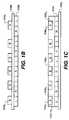
- FIG. 1Bis a schematic side view, in cross section of an improved image product
- FIG. 1Cis a schematic side view, in cross section of an improved stereoscopic image product formed in accordance with the present invention.
- FIGS. 1D and 1Eare schematic side views, in cross section of a color shifting image products formed in accordance with the present invention.
- FIG. 1Fis a schematic side view, in cross section of a motion image product formed in accordance with the present invention.
- FIG. 2Ais a flow chart illustrating an exemplary method in accordance with the present invention.
- FIG. 2Bis a flow chart illustrating another exemplary method in accordance with the present invention.
- FIG. 2Cis a flow chart illustrating another exemplary method in accordance with the present invention.
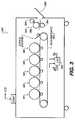
- FIG. 3is a schematic side elevational view, in cross section, of a typical electrographic reproduction apparatus suitable for use with this invention.
- FIG. 4is a schematic side elevational view, in cross section, of the reprographic image-producing portion of the electrographic reproduction apparatus of FIG. 3 , on an enlarged scale;
- FIG. 5is a schematic side elevational view, in cross section, of one printing module of the electrographic reproduction apparatus of FIG. 3 , on an enlarged scale.
- the present inventionis a method of producing an image product including applying a base image to an image receiving surface, applying a clear toner on the base image, and applying a second toner on the clear toner to form at least one barrier in various manners as discussed in detail below.
- FIG. 1Bis a schematic side view, in cross section, of a stereoscopic image product using barriers.
- stereoscopic image products that use barriers to produce the stereoscopic imagesinclude a base image 102 b formed on a backside of a transparent substrate 108 b , and the barriers 104 b 1 - 104 b n are printed on the front side of transparent substrate 108 b .
- the backside of the stereoscopic imagemay be illuminated to increase the three-dimensional effect or the stereoscopic image can be laminated to another substrate.
- Other types of barrier imagesinclude motion images and color-shifting images. Barrier images can appear to move when the viewing angle is changed. These are referred to as motion images. It is possible to print barrier images that produce a color shift when the viewing angle is changed. These are referred to as color-shifting images.
- a receiver member 108 csequentially receives a base image 102 c , a layer of clear toner 110 c and a layer of barrier images 104 c 1 - 104 c n to produce a stereoscopic image.
- the base imagecan be composed of combinations of three colors, such as yellow, magenta and cyan (YMC) or the base image can be composed of combinations of four colors, such as cyan, magenta, yellow, and black (CMYK).
- the term base imagebroadly includes any type of image (e.g., logos, pictoral images), text and/or a combination of both.
- the barriers 104 c 1 - 104 c ncan be printed in recesses 105 c 1 - 105 c i - 105 c n in the layer of clear toner 110 c as shown in FIG. 1C or they can be applied in relief to the outer surface of the layer of clear toner 110 c , similar to the barriers in FIG. 1B .
- FIG. 1Cis a schematic side view, in cross section of an improved stereoscopic image product formed in accordance with the present invention that can be printed on one side of a substrate and in which the barrier is recessed into the transparent layer to produce a smooth outer surface that results in a thinner transparent layer in those areas.
- FIGS. 1D and 1Eare schematic side views, in cross section of a color shifting image products formed in accordance with the present invention.
- the colors 1 - 4 showncould alternately be primary colors or composite colors made up of multiple primaries.
- Color-shifting imagesare illustrated in FIGS. 1D and 1E .
- a base image of, for example, three different colors 102 d 1 - 102 d 3is initially formed on a receiver member 108 d .
- a clear toner 110 dis applied and finally an opaque color 104 d is applied as a barrier.
- a base image of, for example, two different colors 102 e 1 and 102 e 2is initially formed on a receiver member 108 d .
- a clear toner 110 eis applied and finally a translucent or transparent color of barriers 104 e 1 and 104 e n is applied.
- the use of a translucent or transparent color barrier in FIG. 1Ealso provides color shifting in which a viewer sees subtractive colors based on a combination of the barrier color and the base image color.
- the color shifting imagescan be used in a variety of applications.
- the color shifting imagescan be used for security imaging with moiré between the barrier and the underlying image by printing the outer separation at a different screen frequency from the underlying image.
- the underlying image 102 emay also contain characters or other data with regions printed in one or more colors.
- the security imagingcan be used in any type of application, such as currency to allow a background to change colors depending upon viewing angle, make portions of the image appear to move (i.e., a person winking), and/or the like.
- the color shiftingcan be used for any type of element including, but not limited to, text, logos, pictoral images or any other normally halftoned element of an image.
- the arrangement of colors described above in connection with FIGS. 1C-1Eis merely exemplary and that the colors can be provided in different arrangements, so long as the barriers are separated from the base image with a layer of clear toner.
- the particular shapes of the barriersare merely exemplary, and the barriers can take any number of different shapes including, but not limited to, strips, dots, arcs, triangles, square, text or pictographs.
- the receiver membercan be any type of product, including plain paper, clear substrates, reflective substrates (e.g., Mylar) and/or the like.
- FIG. 1Fshows an embodiment of barrier imaging that is used for motion images.
- Image 1 or image 2is visible at different viewing angles. As the viewing angle of an observer changes, for example, by walking past the image, image 1 or image 2 is visible. The image that is not visible is obscured by the barrier.
- image 1 and image 2are interdigitated.
- the thickness of the clear toner layer and the width of the barriers relative to each otherare at a ratio, as shown in Table 2 below that allows the plurality of interdigitated images to be observable in series as a viewing angle of an observer changes, producing a moving image when observed by an observer that is in motion.
- the viewing angle change to obscure one image and allow the other image to be viewedis determined by the arctangent of the ratio of the width of the at least one barrier image, usually one pixel, to the thickness of the clear layer.
- barriers made from tonercan be from 5 to 15 microns thick. In this example, barriers of 11 microns are contemplated. Clear toner layers of 17 to 20 microns thick and up to approximately 60 microns in thickness are used.
- a light ray entering each eye from a point on a substratemakes an angle of approximately 4.76 degrees from perpendicular.
- the thickness of the clear layer between the top of the barrier and the top of the image for common printer resolution in dots per inch (DPI)is given in TABLE 1.
- TABLE 1Clear layer Resolution Pixel width thickness (DPI) (microns) (microns) 600 42.3 254 1200 21.2 127 2400 10.6 63.5 4800 5.3 31.75
- DPIPixel width thickness
- TABLE 2shows for motion images and for color-shifting images the viewing angle for 60 micron and 18 micron thick transparent layers. Here the barrier is aligned with the pixels of the underlying images.
- FIG. 2Ais a flow chart illustrating an exemplary method in accordance with the present invention.
- image datais received (step 205 ) and portions of the received image data that are to include barriers are identified (step 210 ).
- a letter, envelope or other printed productcan include portions that have stereoscopic or color-shifting images and portions that include regular images, and these different portions are identified for use in the printing process.
- Image commandsare then generated based on the received image data and the portions that are to include stereoscopic or color-shifting images (step 215 ) and an image product is printed based on the printer commands (step 220 ).
- Steps 205 - 215can be performed using a general purpose computer with a suitable printer driver and/or using specific purpose hardware and software (e.g., an application specific integrated circuit (ASIC) and/or a field programmable gate array (FPGA).
- ASICapplication specific integrated circuit
- FPGAfield programmable gate array
- Step 220is performed using a printer, and the printing process will be described in more detail in connection with FIG. 2B .
- the printing commandsare received by the printer (step 225 ) and the first, second, third, and any additional toner colors are successively applied to a suitable receiver member in accordance with the printer commands (steps 230 - 240 ).
- a clear toneris applied to the receiver member in accordance with the printer commands (step 245 ) in register with the previous images, and a barrier image toner is then applied to the receiver member in accordance with the printer commands (step 250 ) in register with the previous images.
- the clear tonercan be applied such that portions including barriers have less clear toner than portions that do not include barriers.
- Thisprovides a smooth surface to the resultant image product. This is also an additional security feature that makes images less easily modified.
- This productis described in this embodiment as printed on a substrate or receiver but one skilled in the art understands that the invention could also be printed on a printer intermediate, such as a web and then transferred to a receiver. The print method could be performed in any order, including the one described and others described below, as is appropriate for the printing process used.
- One embodiment of an alternate printing methoduses an intermediate transfer surface, such as a web or roller, to collect the image before it is transferred to a receiver.
- the method of producing an image product using the intermediate transfer surfaceincludes the steps of applying an image to an intermediate image receiving surface wherein the image includes at least one barrier image, applying a clear toner on the at least one barrier image and then applying a second and/or additional images on the clear toner to form a plurality of interdigitated images that can be transferred to a receiver.
- the color of the barrier image tonerwill depend upon whether a stereoscopic image is being applied, in which case the barrier color should be opaque. Additionally, if color shifting is being performed using an opaque barrier (as illustrated in FIG. 1D ), then the barrier image toner will be opaque; and if color shifting is being performed using a translucent or transparent barrier (as illustrated in FIG. 1E ), then the barrier image toner can be any type of translucent or transparent color toner. In the latter case, the interaction between the color of the barrier image and the colors of the underlying should be considered to achieve a desired effect.
- the tonercan be applied, for example, in the order of yellow, magenta, cyan, clear and black (YMCLK) or black, yellow, magenta, cyan, clear and black (KYMCLK).
- the barriercan be black, white, or any other color.
- any number of colors usedsuch as a single color image, such as can be printed on the NexPress Digimatster, or multiple color images, such as can be printed using the NexPress 2100 or similar printers using an intermediate web.
- the tonercan be applied, for example, in the order of black, yellow, magenta, clear and cyan (KYMLC) such that at viewing angles where cyan overlaps yellow the image has a more greenish tint and at viewing angles where cyan overlaps magenta the image has a more bluish tint.
- Color shifting imagescan also have toner applied, for example, in the order of black, yellow, cyan, clear and magenta (KYCLM) such that at viewing angles where magenta overlaps cyan the image will have a bluish tint and where magenta overlaps yellow the image will have a reddish tint.
- Step 255the resultant image product is applied to a fuser in order to fuse the applied toner to the receiving member (step 255 ).
- Steps 220 - 255can be performed using any type of processor in a printer, including an application specific integrated circuit (ASIC) and/or a field programmable gate array (FPGA).
- ASICapplication specific integrated circuit
- FPGAfield programmable gate array
- the resulting image productcan be any type of product, such as a multi-language packaging, warning labels, motion imaging in posters, children's books, compact disc (CD) or digital versatile disc (DVD) cases, trading cards, mouse pads, counter displays, key rings, framed pictures, bank checks, security documents, currency, and/or the like.
- the resulting image productcan be backlit when, for example, the product is a poster.
- FIG. 2Cis a flow chart illustrating another exemplary method in accordance with the present invention.
- image datais received and portions of the received image data that are to include barriers are identified.
- Image commandsare then generated based on the received image data and an image product is printed based on the printer commands.
- the printing commandsare received by the printer (step 266 ) and a barrier image toner is then applied to the intermediate transfer surface, such as a web as shown in FIG. 3 , and then transferred to a receiver in accordance with the printer commands (step 268 ).
- a clear toneris applied to the receiver member in accordance with the printer commands (step 270 ) in registration with the previous images.
- the clear tonercan be applied such that portions including barriers have less clear toner than portions that do not include barriers. This provides a smooth surface to the resultant image product. This is also an additional security feature that makes images less easily modified.
- additional color layersare successively applied to the intermediate receiving surface in accordance with the printer commands (steps 272 - 278 ), such as a first, second, third, and any additional toner colors before these layers are transferred to a receiver (step 280 ) and fused (step 282 ).
- FIGS. 3-5are side elevational views schematically showing portions of a typical electrographic print engine or printer apparatus suitable for printing of pentachrome images.
- FIGS. 3-5are side elevational views schematically showing portions of a typical electrographic print engine or printer apparatus suitable for printing of pentachrome images.
- one embodiment of the inventioninvolves printing using an electrophotographic engine having three sets of single color image producing or printing stations or modules arranged in tandem, the invention contemplates that more or less than three colors may be combined on a single receiver member, or may include other typical electrographic writers or printer apparatus.
- An electrographic printer apparatus 300shows an electrophotograghic printer having an intermediate transfer surface that has a number of tandemly arranged electrostatographic image forming printing modules M 1 , M 2 , M 3 , M 4 , and M 5 .
- Each of the printing modules M 1 , M 3 , M 4 , and M 5generates a single-color toner image and printing module M 2 includes a clear toner for transfer of clear images to a receiver member successively moved through the modules.
- Each receiver memberduring a single pass through the five modules M 1 -M 5 , can have transferred in registration thereto up to four single-color toner images (which can form a CMYK process color image) and one clear toner image.
- process colorimplies that in an image formed on a receiver member combinations of subsets of the four colors are combined to form other colors on the receiver member at various locations on the receiver member, and that all four colors participate to form process colors in at least some of the subsets wherein each of the four colors may be combined with one or more of the other colors at a particular location on the receiver member to form a color different than the specific color toners combined at that location.
- printing modules M 1 , M 3 , M 4 and M 5can each form color separation images using any combination of colors, such as black (K), cyan (C), magenta (M), yellow (Y) and black (K); red (R), green (G) and blue (B); and/or the like.
- printing modules M 3 -M 5can be used to produce yellow (Y), magenta (M), and cyan (C) separations
- module M 2can produce a clear toner layer
- module M 1can produce a barrier using black (K) or another color toner.
- the printerhas receiver members (R n -R (n-6) as shown in FIG. 4 ) are delivered from a paper supply unit (not shown) and transported through the printing modules M 1 -M 5 .
- the receiver membersare adhered (e.g., preferably electrostatically via coupled corona tack-down chargers 324 , 325 ) to an endless transport web 301 entrained and driven about rollers 302 , 303 .
- Each of the printing modules M 1 -M 5similarly includes a photoconductive imaging roller, an intermediate transfer member roller, and a transfer backup roller.
- a first color toner separation imagecan be created on the photoconductive imaging roller PC 1 ( 311 ), transferred to intermediate transfer member roller ITM 1 ( 312 ), and transferred again to a receiver member moving through a transfer station, which transfer station includes ITM 1 forming a pressure nip with a transfer backup roller TR 1 ( 313 ).
- printing modules M 2 , M 3 , M 4 , and M 5include, respectively: PC 2 , ITM 2 , TR 2 ( 321 , 322 , 323 ); PC 3 , ITM 3 , TR 3 ( 331 , 332 , 333 ); PC 4 , ITM 4 , TR 4 ( 341 , 342 , 343 ); and PC 5 , ITM 5 , TR 5 ( 351 , 352 , 353 ).
- a receiver member, R narriving from the supply, is shown passing over roller 302 for subsequent entry into the transfer station of the first printing module, M 1 , in which the preceding receiver member R (n-1) is shown.
- receiver members R (n-2) , R (n-3) , R (n-4) , and R (n-5)are shown moving respectively through the transfer stations of printing modules M 2 , M 3 , M 4 , and M 5 .
- An unfused image formed on receiver member R (n-6)is moving as shown towards a fuser of any well known construction, such as the fuser assembly 360 (shown in FIG. 3 ).
- a power supply unit 305provides individual transfer currents to the transfer backup rollers TR 1 , TR 2 , TR 3 , TR 4 , and TR 5 respectively.
- a logic and control unit 430( FIG. 3 ) includes one or more computers and in response to signals from various sensors associated with the electrophotographic printer apparatus 300 provides timing and control signals to the respective components to provide control of the various components and process control parameters of the apparatus in accordance with well understood and known employments.
- a cleaning station 301 a for transport web 301is also typically provided to allow continued reuse thereof.
- each printing module of the electrographic printer apparatus 300includes a plurality of electrographic imaging subsystems for producing a single color toned image or a clear image (in the case of M 4 ). Included in each printing module is a primary charging subsystem 410 for uniformly electrostatically charging a surface 406 of a photoconductive imaging member (shown in the form of an imaging cylinder 405 ). An exposure subsystem 420 is provided for image-wise modulating the uniform electrostatic charge by exposing the photoconductive imaging member to form a latent electrostatic color separation image of the respective color.
- a primary charging subsystem 410for uniformly electrostatically charging a surface 406 of a photoconductive imaging member (shown in the form of an imaging cylinder 405 ).
- An exposure subsystem 420is provided for image-wise modulating the uniform electrostatic charge by exposing the photoconductive imaging member to form a latent electrostatic color separation image of the respective color.
- a development station subsystem 425serves for toning the image-wise exposed photoconductive imaging member with toner of a respective color (or clear toner).
- An intermediate transfer member 415is provided for transferring the respective color separation image (or clear toner separation image) from the photoconductive imaging member through a transfer nip 401 to the surface 416 of the intermediate transfer member 415 and from the intermediate transfer member 415 to a receiver member (receiver member 436 shown prior to entry into the transfer nip and receiver member 437 shown subsequent to transfer of the toned color or clear separation image) which receives the respective toned color separation images and the clear separation image in superposition to form a composite multicolor image and barrier image thereon.
- the receiver memberis advanced to a fusing assembly to fuse the multicolor and clear toner image to the receiver member.
- Additional necessary components provided for controlmay be assembled about the various process elements of the respective printing modules (e.g., a meter 411 for measuring the uniform electrostatic charge, a meter 412 for measuring the post-exposure surface potential within a patch area of a patch latent image formed from time to time in a non-image area on surface 406 , etc).
- Further details regarding the electrographic printer apparatus 300are provided in U.S. Publication No. 2006/0133870, published on Jun. 22, 2006, in the name of Yee S.
- Ng et al and of the printing processprovided in U.S. Publication No. 2008/0159786, published on Jul. 3, 2008 in the name of Thomas Tombs et al. each of which are hereby incorporated by reference.
- One preferred method of rendering an image in conjunction with these embodimentsis to use a continuous toned image of variable density as described in TechnologE Watch Vol. 11 Fall 2006.
- a main printer apparatus logic and control unit (LCU) 430which receives input signals from the various sensors associated with the printer apparatus and sends control signals to the chargers 410 , the exposure subsystem 420 (e.g., LED writers), and the development stations 425 of the printing modules M 1 -M 5 .
- Each printing modulemay also have its own respective controller coupled to the printer apparatus main LCU 430 .
- the receiver memberis then serially de-tacked from transport web 301 and sent in a direction to the fusing assembly 360 to fuse or fix the dry toner images to the receiver member.
- the transport webis then reconditioned for reuse by cleaning and providing charge to both surfaces 324 , 325 (see FIG. 4 ) which neutralizes charge on the opposed surfaces of the transport web 301 .
- the electrostatic imageis developed by application of pigmented (or non-pigmented) marking particles (toner) to the latent image bearing photoconductive drum by the respective development station 425 .
- Each of the development stations of the respective printing modules M 1 -M 5is electrically biased by a suitable respective voltage to develop the respective latent image, which voltage may be supplied by a power supply or by individual power supplies (not illustrated).
- the respective developeris a two-component developer that includes toner marking particles and magnetic carrier particles.
- the toner marking particlescan be, for example, polyester based.
- Each color development stationhas a particular color of pigmented toner marking particles associated respectively therewith for toning or a clear toner (i.e., non-pigmented) respectively associated therewith.
- each of the five modulescreates a different color marking particle image or a clear toner image on the respective photoconductive drum.
- transport belt 301transports the toner image carrying receiver members to a fusing or fixing assembly 360 , which fixes the toner particles to the respective receiver members by the application of heat and pressure.
- fusing assembly 360includes a heated fusing roller 362 and an opposing pressure roller 364 that form a fusing nip therebetween.
- Fusing assembly 360also includes a release fluid application substation generally designated 368 that applies release fluid, such as, for example, silicone oil, to fusing roller 362 .
- release fluidsuch as, for example, silicone oil
- the logic and control unit (LCU) 430includes a microprocessor incorporating suitable look-up tables and control software, which is executable by the LCU 430 .
- the control softwareis preferably stored in memory associated with the LCU 430 .
- Sensors associated with the fusing assemblyprovide appropriate signals to the LCU 430 .
- the LCU 430issues command and control signals that adjust the heat and/or pressure within fusing nip 366 and otherwise generally nominalizes and/or optimizes the operating parameters of fusing assembly 360 for imaging substrates.
- Image data for writing by the printer apparatus 300may be processed by a raster image processor (RIP), which may include a color separation screen generator or generators.
- the output of the RIPmay be stored in frame or line buffers for transmission of the color separation print data to each of respective LED writers.
- the RIP and/or color separation screen generatormay be a part of the printer apparatus or remote therefrom.
- Image data processed by the RIPmay be obtained from a color document scanner or a digital camera or generated by a computer or from a memory or network which typically includes image data representing a continuous image that needs to be reprocessed into halftone image data in order to be adequately represented by the printer.
- the RIPmay perform image processing processes including color correction, etc. in order to obtain the desired color print.
- Color image datais separated into the respective colors and can be converted by the RIP to halftone dot image data in the respective color using matrices, which comprise desired screen angles and screen rulings.
- the RIPmay be a suitably programmed computer and/or logic devices and is adapted to employ stored or generated matrices and templates for processing separated color image data into rendered image data in the form of halftone information suitable for printing. Portions of the image can also be printed as continuous tone images of variable density.
Landscapes
- Physics & Mathematics (AREA)
- Engineering & Computer Science (AREA)
- Multimedia (AREA)
- Signal Processing (AREA)
- General Physics & Mathematics (AREA)
- Optics & Photonics (AREA)
- Color Electrophotography (AREA)
Abstract
Description
| TABLE 1 | ||
| Clear | ||
| layer | ||
| Resolution | Pixel width | thickness |
| (DPI) | (microns) | (microns) |
| 600 | 42.3 | 254 |
| 1200 | 21.2 | 127 |
| 2400 | 10.6 | 63.5 |
| 4800 | 5.3 | 31.75 |
TABLE 2 shows for motion images and for color-shifting images the viewing angle for 60 micron and 18 micron thick transparent layers. Here the barrier is aligned with the pixels of the underlying images.
| TABLE 2 | |||
| Viewing angle change (degrees from normal) | |||
| Transparent thickness . . . | |||
| 60 micron | 18 micron | 60 micron | 18 micron | |
| Barrier | Barrier | Color-shift | Color-shift | |
| dpi | Image | Image | Image | Image |
| 600 | 35.18384 | 66.9487 | 9.995722 | 30.43424 |
| 1200 | 19.46001 | 49.66686 | 5.048025 | 16.40677 |
| 2400 | 10.01887 | 30.49336 | 2.52892 | 8.37505 |
| 4800 | 5.048025 | 16.40677 | 1.265076 | 4.210013 |
Claims (16)
Priority Applications (2)
| Application Number | Priority Date | Filing Date | Title |
|---|---|---|---|
| US12/396,779US8180267B2 (en) | 2009-03-03 | 2009-03-03 | Electrophotographically produced barrier images using an intermediate transfer member |
| PCT/US2010/000463WO2010101603A1 (en) | 2009-03-03 | 2010-02-18 | Electrophotographically produced barrier images using an intermediate transfer member |
Applications Claiming Priority (1)
| Application Number | Priority Date | Filing Date | Title |
|---|---|---|---|
| US12/396,779US8180267B2 (en) | 2009-03-03 | 2009-03-03 | Electrophotographically produced barrier images using an intermediate transfer member |
Publications (2)
| Publication Number | Publication Date |
|---|---|
| US20100226692A1 US20100226692A1 (en) | 2010-09-09 |
| US8180267B2true US8180267B2 (en) | 2012-05-15 |
Family
ID=42145912
Family Applications (1)
| Application Number | Title | Priority Date | Filing Date |
|---|---|---|---|
| US12/396,779Expired - Fee RelatedUS8180267B2 (en) | 2009-03-03 | 2009-03-03 | Electrophotographically produced barrier images using an intermediate transfer member |
Country Status (2)
| Country | Link |
|---|---|
| US (1) | US8180267B2 (en) |
| WO (1) | WO2010101603A1 (en) |
Families Citing this family (3)
| Publication number | Priority date | Publication date | Assignee | Title |
|---|---|---|---|---|
| US8301062B2 (en)* | 2009-03-03 | 2012-10-30 | Eastman Kodak Company | Electrophotographically produced barrier images |
| CN102802006B (en)* | 2012-08-03 | 2014-08-06 | 梁智伟 | Digital camera, laminated photo printer and stereoscopic color image production system |
| JP6885123B2 (en)* | 2017-03-15 | 2021-06-09 | 富士フイルムビジネスイノベーション株式会社 | Image forming device |
Citations (26)
| Publication number | Priority date | Publication date | Assignee | Title |
|---|---|---|---|---|
| US3161509A (en) | 1962-04-24 | 1964-12-15 | Eastman Kodak Co | Line stereo color pictures |
| JPH01132706A (en)* | 1987-11-18 | 1989-05-25 | Nkk Corp | How to stir slag and molten metal |
| JPH0433880A (en)* | 1990-05-30 | 1992-02-05 | Ookurashiyou Insatsu Kyokucho | Stereoscopic image printing product by use of transparent medium and parallax barrier and manufacture thereof |
| US5178928A (en) | 1988-09-22 | 1993-01-12 | Dai Nippon Insatsu Kabushiki Kaisha | Decorative materials |
| US5260753A (en) | 1990-11-14 | 1993-11-09 | Konica Corporation | Color image forming method |
| US5359454A (en)* | 1992-08-18 | 1994-10-25 | Applied Physics Research, L.P. | Apparatus for providing autostereoscopic and dynamic images |
| US5398131A (en)* | 1992-08-13 | 1995-03-14 | Hall; Dennis R. | Stereoscopic hardcopy methods |
| JPH07244343A (en) | 1994-03-03 | 1995-09-19 | Sanyo Electric Co Ltd | Stereoscopic photograph |
| JPH11327065A (en)* | 1998-05-19 | 1999-11-26 | Fuji Photo Film Co Ltd | Image recording method and thermosensitive recording medium |
| US6103345A (en) | 1995-02-12 | 2000-08-15 | Meiwa Gravure Co., Ltd. | Decorative sheet with changeable color or density |
| JP2002072613A (en) | 2000-08-23 | 2002-03-12 | Konica Corp | Image forming device |
| US6465077B1 (en) | 2000-01-25 | 2002-10-15 | 3M Innovative Properties Company | Black line screens and methods of making same |
| US6464348B1 (en)* | 2000-11-13 | 2002-10-15 | Hewlett-Packard Company | Base materials for a clear protective overcoat on inkjet images |
| JP2004163797A (en)* | 2002-11-15 | 2004-06-10 | Toppan Printing Co Ltd | Anti-counterfeit medium exhibiting polarization and authenticity determination method using the same |
| JP2005099822A (en)* | 2004-10-22 | 2005-04-14 | Matsushita Electric Ind Co Ltd | Stereoscopic image display device |
| US20060133870A1 (en) | 2004-12-22 | 2006-06-22 | Ng Yee S | Method and apparatus for printing using a tandem electrostatographic printer |
| WO2006133512A1 (en)* | 2005-06-17 | 2006-12-21 | Securency Pty Limited | Security documents incorporating colour shifting inks |
| DE102006003311A1 (en) | 2006-01-23 | 2007-07-26 | Man Roland Druckmaschinen Ag | Method for producing printed image effects with directional viewing by applying spatial pattern lacquer layer to form mini lens array |
| JP2007187768A (en)* | 2006-01-12 | 2007-07-26 | Nakagawa Chem:Kk | Method of forming pseudo stereoscopic image, decorating or advertizing method using the pseudo stereoscopic image |
| US20070273142A1 (en)* | 2004-04-03 | 2007-11-29 | Ovd Kinegram Ag | Security element provided in the form of a multilayered film body |
| US20080159786A1 (en) | 2006-12-27 | 2008-07-03 | Thomas Nathaniel Tombs | Selective printing of raised information by electrography |
| US20080171144A1 (en)* | 2002-09-13 | 2008-07-17 | Jds Uniphase Corporation | Printed Magnetic Ink Overt Security Image |
| US20090097114A1 (en)* | 2005-04-11 | 2009-04-16 | Nippon Carbide Kogyo Kabushiki Kaisha | Printed image-set retroreflective sheeting |
| US7688474B2 (en)* | 2005-10-31 | 2010-03-30 | Xerox Corporation | Moiré-based auto-stereoscopic images by duplex printing on transparencies |
| US7699350B2 (en)* | 2002-02-14 | 2010-04-20 | Giesecke & Devrient Gmbh | Security element and security document with one such security element |
| US20100226693A1 (en)* | 2009-03-03 | 2010-09-09 | Stelter Eric C | Electrophotographically produced barrier images |
- 2009
- 2009-03-03USUS12/396,779patent/US8180267B2/ennot_activeExpired - Fee Related
- 2010
- 2010-02-18WOPCT/US2010/000463patent/WO2010101603A1/enactiveApplication Filing
Patent Citations (28)
| Publication number | Priority date | Publication date | Assignee | Title |
|---|---|---|---|---|
| US3161509A (en) | 1962-04-24 | 1964-12-15 | Eastman Kodak Co | Line stereo color pictures |
| JPH01132706A (en)* | 1987-11-18 | 1989-05-25 | Nkk Corp | How to stir slag and molten metal |
| US5178928A (en) | 1988-09-22 | 1993-01-12 | Dai Nippon Insatsu Kabushiki Kaisha | Decorative materials |
| JPH0433880A (en)* | 1990-05-30 | 1992-02-05 | Ookurashiyou Insatsu Kyokucho | Stereoscopic image printing product by use of transparent medium and parallax barrier and manufacture thereof |
| US5260753A (en) | 1990-11-14 | 1993-11-09 | Konica Corporation | Color image forming method |
| US5398131A (en)* | 1992-08-13 | 1995-03-14 | Hall; Dennis R. | Stereoscopic hardcopy methods |
| US5359454A (en)* | 1992-08-18 | 1994-10-25 | Applied Physics Research, L.P. | Apparatus for providing autostereoscopic and dynamic images |
| US5461495A (en)* | 1992-08-18 | 1995-10-24 | Applied Physics Research, L.P. | Apparatus for providing autostereoscopic and dynamic images and method of manufacturing same |
| US5568313A (en)* | 1992-08-18 | 1996-10-22 | Applied Physics Research, L.P. | Apparatus for providing autostereoscopic and dynamic images and method of manufacturing same |
| JPH07244343A (en) | 1994-03-03 | 1995-09-19 | Sanyo Electric Co Ltd | Stereoscopic photograph |
| US6103345A (en) | 1995-02-12 | 2000-08-15 | Meiwa Gravure Co., Ltd. | Decorative sheet with changeable color or density |
| JPH11327065A (en)* | 1998-05-19 | 1999-11-26 | Fuji Photo Film Co Ltd | Image recording method and thermosensitive recording medium |
| US6465077B1 (en) | 2000-01-25 | 2002-10-15 | 3M Innovative Properties Company | Black line screens and methods of making same |
| JP2002072613A (en) | 2000-08-23 | 2002-03-12 | Konica Corp | Image forming device |
| US6464348B1 (en)* | 2000-11-13 | 2002-10-15 | Hewlett-Packard Company | Base materials for a clear protective overcoat on inkjet images |
| US7699350B2 (en)* | 2002-02-14 | 2010-04-20 | Giesecke & Devrient Gmbh | Security element and security document with one such security element |
| US20080171144A1 (en)* | 2002-09-13 | 2008-07-17 | Jds Uniphase Corporation | Printed Magnetic Ink Overt Security Image |
| JP2004163797A (en)* | 2002-11-15 | 2004-06-10 | Toppan Printing Co Ltd | Anti-counterfeit medium exhibiting polarization and authenticity determination method using the same |
| US20070273142A1 (en)* | 2004-04-03 | 2007-11-29 | Ovd Kinegram Ag | Security element provided in the form of a multilayered film body |
| JP2005099822A (en)* | 2004-10-22 | 2005-04-14 | Matsushita Electric Ind Co Ltd | Stereoscopic image display device |
| US20060133870A1 (en) | 2004-12-22 | 2006-06-22 | Ng Yee S | Method and apparatus for printing using a tandem electrostatographic printer |
| US20090097114A1 (en)* | 2005-04-11 | 2009-04-16 | Nippon Carbide Kogyo Kabushiki Kaisha | Printed image-set retroreflective sheeting |
| WO2006133512A1 (en)* | 2005-06-17 | 2006-12-21 | Securency Pty Limited | Security documents incorporating colour shifting inks |
| US7688474B2 (en)* | 2005-10-31 | 2010-03-30 | Xerox Corporation | Moiré-based auto-stereoscopic images by duplex printing on transparencies |
| JP2007187768A (en)* | 2006-01-12 | 2007-07-26 | Nakagawa Chem:Kk | Method of forming pseudo stereoscopic image, decorating or advertizing method using the pseudo stereoscopic image |
| DE102006003311A1 (en) | 2006-01-23 | 2007-07-26 | Man Roland Druckmaschinen Ag | Method for producing printed image effects with directional viewing by applying spatial pattern lacquer layer to form mini lens array |
| US20080159786A1 (en) | 2006-12-27 | 2008-07-03 | Thomas Nathaniel Tombs | Selective printing of raised information by electrography |
| US20100226693A1 (en)* | 2009-03-03 | 2010-09-09 | Stelter Eric C | Electrophotographically produced barrier images |
Non-Patent Citations (1)
| Title |
|---|
| I TechnologE Watch, vol. 11, Fall 2006. |
Also Published As
| Publication number | Publication date |
|---|---|
| WO2010101603A1 (en) | 2010-09-10 |
| US20100226692A1 (en) | 2010-09-09 |
Similar Documents
| Publication | Publication Date | Title |
|---|---|---|
| US8301062B2 (en) | Electrophotographically produced barrier images | |
| US8358957B2 (en) | Selective printing of raised information by electrography | |
| US8064788B2 (en) | Selective printing of raised information using electrography | |
| US4903048A (en) | Simulated color imaging using only two different colorants/toners | |
| US4650421A (en) | Representation of color for blind persons | |
| JP2010533314A (en) | Printing optical elements by electrography | |
| EP2168013A1 (en) | Printing of raised multidimensional toner by electrography | |
| CN102763044B (en) | Embossed printing using small toner particles | |
| US20140004462A1 (en) | Making article with desired profile | |
| EP2539779B1 (en) | Interchanging color printer and related method | |
| US8099024B2 (en) | Systems and methods of producing gradient index optics by sequential printing of toners having different indices of refraction | |
| US8320784B2 (en) | Enhanced fusing of raised toner using electrography | |
| US8180267B2 (en) | Electrophotographically produced barrier images using an intermediate transfer member | |
| US20110200360A1 (en) | System to print raised printing using small toner particles | |
| EP2278411A1 (en) | Scalable printing system having multiple intermediate transfer belts | |
| US8774679B2 (en) | Electrographic tactile image printing system | |
| US20140322380A1 (en) | Digital embossing device | |
| US20140319739A1 (en) | Digital embossing and creasing | |
| US20140056616A1 (en) | Electrographic printing of tactile images | |
| Schein | Color Electrophotography |
Legal Events
| Date | Code | Title | Description |
|---|---|---|---|
| AS | Assignment | Owner name:EASTMAN KODAK COMPANY, NEW YORK Free format text:ASSIGNMENT OF ASSIGNORS INTEREST;ASSIGNOR:STELTER, ERIC C.;REEL/FRAME:022337/0483 Effective date:20090302 | |
| FEPP | Fee payment procedure | Free format text:PAYOR NUMBER ASSIGNED (ORIGINAL EVENT CODE: ASPN); ENTITY STATUS OF PATENT OWNER: LARGE ENTITY Free format text:PAYER NUMBER DE-ASSIGNED (ORIGINAL EVENT CODE: RMPN); ENTITY STATUS OF PATENT OWNER: LARGE ENTITY | |
| ZAAA | Notice of allowance and fees due | Free format text:ORIGINAL CODE: NOA | |
| ZAAB | Notice of allowance mailed | Free format text:ORIGINAL CODE: MN/=. | |
| AS | Assignment | Owner name:CITICORP NORTH AMERICA, INC., AS AGENT, NEW YORK Free format text:SECURITY INTEREST;ASSIGNORS:EASTMAN KODAK COMPANY;PAKON, INC.;REEL/FRAME:028201/0420 Effective date:20120215 | |
| STCF | Information on status: patent grant | Free format text:PATENTED CASE | |
| AS | Assignment | Owner name:WILMINGTON TRUST, NATIONAL ASSOCIATION, AS AGENT, MINNESOTA Free format text:PATENT SECURITY AGREEMENT;ASSIGNORS:EASTMAN KODAK COMPANY;PAKON, INC.;REEL/FRAME:030122/0235 Effective date:20130322 Owner name:WILMINGTON TRUST, NATIONAL ASSOCIATION, AS AGENT, Free format text:PATENT SECURITY AGREEMENT;ASSIGNORS:EASTMAN KODAK COMPANY;PAKON, INC.;REEL/FRAME:030122/0235 Effective date:20130322 | |
| AS | Assignment | Owner name:BANK OF AMERICA N.A., AS AGENT, MASSACHUSETTS Free format text:INTELLECTUAL PROPERTY SECURITY AGREEMENT (ABL);ASSIGNORS:EASTMAN KODAK COMPANY;FAR EAST DEVELOPMENT LTD.;FPC INC.;AND OTHERS;REEL/FRAME:031162/0117 Effective date:20130903 Owner name:BARCLAYS BANK PLC, AS ADMINISTRATIVE AGENT, NEW YORK Free format text:INTELLECTUAL PROPERTY SECURITY AGREEMENT (SECOND LIEN);ASSIGNORS:EASTMAN KODAK COMPANY;FAR EAST DEVELOPMENT LTD.;FPC INC.;AND OTHERS;REEL/FRAME:031159/0001 Effective date:20130903 Owner name:JPMORGAN CHASE BANK, N.A., AS ADMINISTRATIVE, DELAWARE Free format text:INTELLECTUAL PROPERTY SECURITY AGREEMENT (FIRST LIEN);ASSIGNORS:EASTMAN KODAK COMPANY;FAR EAST DEVELOPMENT LTD.;FPC INC.;AND OTHERS;REEL/FRAME:031158/0001 Effective date:20130903 Owner name:JPMORGAN CHASE BANK, N.A., AS ADMINISTRATIVE, DELA Free format text:INTELLECTUAL PROPERTY SECURITY AGREEMENT (FIRST LIEN);ASSIGNORS:EASTMAN KODAK COMPANY;FAR EAST DEVELOPMENT LTD.;FPC INC.;AND OTHERS;REEL/FRAME:031158/0001 Effective date:20130903 Owner name:EASTMAN KODAK COMPANY, NEW YORK Free format text:RELEASE OF SECURITY INTEREST IN PATENTS;ASSIGNORS:CITICORP NORTH AMERICA, INC., AS SENIOR DIP AGENT;WILMINGTON TRUST, NATIONAL ASSOCIATION, AS JUNIOR DIP AGENT;REEL/FRAME:031157/0451 Effective date:20130903 Owner name:PAKON, INC., NEW YORK Free format text:RELEASE OF SECURITY INTEREST IN PATENTS;ASSIGNORS:CITICORP NORTH AMERICA, INC., AS SENIOR DIP AGENT;WILMINGTON TRUST, NATIONAL ASSOCIATION, AS JUNIOR DIP AGENT;REEL/FRAME:031157/0451 Effective date:20130903 Owner name:BARCLAYS BANK PLC, AS ADMINISTRATIVE AGENT, NEW YO Free format text:INTELLECTUAL PROPERTY SECURITY AGREEMENT (SECOND LIEN);ASSIGNORS:EASTMAN KODAK COMPANY;FAR EAST DEVELOPMENT LTD.;FPC INC.;AND OTHERS;REEL/FRAME:031159/0001 Effective date:20130903 | |
| FPAY | Fee payment | Year of fee payment:4 | |
| AS | Assignment | Owner name:KODAK (NEAR EAST), INC., NEW YORK Free format text:RELEASE BY SECURED PARTY;ASSIGNOR:JP MORGAN CHASE BANK, N.A., AS ADMINISTRATIVE AGENT;REEL/FRAME:050239/0001 Effective date:20190617 Owner name:CREO MANUFACTURING AMERICA LLC, NEW YORK Free format text:RELEASE BY SECURED PARTY;ASSIGNOR:JP MORGAN CHASE BANK, N.A., AS ADMINISTRATIVE AGENT;REEL/FRAME:050239/0001 Effective date:20190617 Owner name:KODAK REALTY, INC., NEW YORK Free format text:RELEASE BY SECURED PARTY;ASSIGNOR:JP MORGAN CHASE BANK, N.A., AS ADMINISTRATIVE AGENT;REEL/FRAME:050239/0001 Effective date:20190617 Owner name:NPEC, INC., NEW YORK Free format text:RELEASE BY SECURED PARTY;ASSIGNOR:JP MORGAN CHASE BANK, N.A., AS ADMINISTRATIVE AGENT;REEL/FRAME:050239/0001 Effective date:20190617 Owner name:KODAK PORTUGUESA LIMITED, NEW YORK Free format text:RELEASE BY SECURED PARTY;ASSIGNOR:JP MORGAN CHASE BANK, N.A., AS ADMINISTRATIVE AGENT;REEL/FRAME:050239/0001 Effective date:20190617 Owner name:KODAK AVIATION LEASING LLC, NEW YORK Free format text:RELEASE BY SECURED PARTY;ASSIGNOR:JP MORGAN CHASE BANK, N.A., AS ADMINISTRATIVE AGENT;REEL/FRAME:050239/0001 Effective date:20190617 Owner name:QUALEX, INC., NEW YORK Free format text:RELEASE BY SECURED PARTY;ASSIGNOR:JP MORGAN CHASE BANK, N.A., AS ADMINISTRATIVE AGENT;REEL/FRAME:050239/0001 Effective date:20190617 Owner name:KODAK IMAGING NETWORK, INC., NEW YORK Free format text:RELEASE BY SECURED PARTY;ASSIGNOR:JP MORGAN CHASE BANK, N.A., AS ADMINISTRATIVE AGENT;REEL/FRAME:050239/0001 Effective date:20190617 Owner name:LASER PACIFIC MEDIA CORPORATION, NEW YORK Free format text:RELEASE BY SECURED PARTY;ASSIGNOR:JP MORGAN CHASE BANK, N.A., AS ADMINISTRATIVE AGENT;REEL/FRAME:050239/0001 Effective date:20190617 Owner name:EASTMAN KODAK COMPANY, NEW YORK Free format text:RELEASE BY SECURED PARTY;ASSIGNOR:JP MORGAN CHASE BANK, N.A., AS ADMINISTRATIVE AGENT;REEL/FRAME:050239/0001 Effective date:20190617 Owner name:KODAK AMERICAS, LTD., NEW YORK Free format text:RELEASE BY SECURED PARTY;ASSIGNOR:JP MORGAN CHASE BANK, N.A., AS ADMINISTRATIVE AGENT;REEL/FRAME:050239/0001 Effective date:20190617 Owner name:FPC, INC., NEW YORK Free format text:RELEASE BY SECURED PARTY;ASSIGNOR:JP MORGAN CHASE BANK, N.A., AS ADMINISTRATIVE AGENT;REEL/FRAME:050239/0001 Effective date:20190617 Owner name:KODAK PHILIPPINES, LTD., NEW YORK Free format text:RELEASE BY SECURED PARTY;ASSIGNOR:JP MORGAN CHASE BANK, N.A., AS ADMINISTRATIVE AGENT;REEL/FRAME:050239/0001 Effective date:20190617 Owner name:FAR EAST DEVELOPMENT LTD., NEW YORK Free format text:RELEASE BY SECURED PARTY;ASSIGNOR:JP MORGAN CHASE BANK, N.A., AS ADMINISTRATIVE AGENT;REEL/FRAME:050239/0001 Effective date:20190617 Owner name:PAKON, INC., NEW YORK Free format text:RELEASE BY SECURED PARTY;ASSIGNOR:JP MORGAN CHASE BANK, N.A., AS ADMINISTRATIVE AGENT;REEL/FRAME:050239/0001 Effective date:20190617 | |
| AS | Assignment | Owner name:KODAK (NEAR EAST), INC., NEW YORK Free format text:RELEASE BY SECURED PARTY;ASSIGNOR:JP MORGAN CHASE BANK, N.A., AS ADMINISTRATIVE AGENT;REEL/FRAME:049901/0001 Effective date:20190617 Owner name:QUALEX, INC., NEW YORK Free format text:RELEASE BY SECURED PARTY;ASSIGNOR:JP MORGAN CHASE BANK, N.A., AS ADMINISTRATIVE AGENT;REEL/FRAME:049901/0001 Effective date:20190617 Owner name:KODAK PHILIPPINES, LTD., NEW YORK Free format text:RELEASE BY SECURED PARTY;ASSIGNOR:JP MORGAN CHASE BANK, N.A., AS ADMINISTRATIVE AGENT;REEL/FRAME:049901/0001 Effective date:20190617 Owner name:LASER PACIFIC MEDIA CORPORATION, NEW YORK Free format text:RELEASE BY SECURED PARTY;ASSIGNOR:JP MORGAN CHASE BANK, N.A., AS ADMINISTRATIVE AGENT;REEL/FRAME:049901/0001 Effective date:20190617 Owner name:NPEC, INC., NEW YORK Free format text:RELEASE BY SECURED PARTY;ASSIGNOR:JP MORGAN CHASE BANK, N.A., AS ADMINISTRATIVE AGENT;REEL/FRAME:049901/0001 Effective date:20190617 Owner name:KODAK AVIATION LEASING LLC, NEW YORK Free format text:RELEASE BY SECURED PARTY;ASSIGNOR:JP MORGAN CHASE BANK, N.A., AS ADMINISTRATIVE AGENT;REEL/FRAME:049901/0001 Effective date:20190617 Owner name:PFC, INC., NEW YORK Free format text:RELEASE BY SECURED PARTY;ASSIGNOR:JP MORGAN CHASE BANK, N.A., AS ADMINISTRATIVE AGENT;REEL/FRAME:049901/0001 Effective date:20190617 Owner name:PAKON, INC., NEW YORK Free format text:RELEASE BY SECURED PARTY;ASSIGNOR:JP MORGAN CHASE BANK, N.A., AS ADMINISTRATIVE AGENT;REEL/FRAME:049901/0001 Effective date:20190617 Owner name:FAR EAST DEVELOPMENT LTD., NEW YORK Free format text:RELEASE BY SECURED PARTY;ASSIGNOR:JP MORGAN CHASE BANK, N.A., AS ADMINISTRATIVE AGENT;REEL/FRAME:049901/0001 Effective date:20190617 Owner name:EASTMAN KODAK COMPANY, NEW YORK Free format text:RELEASE BY SECURED PARTY;ASSIGNOR:JP MORGAN CHASE BANK, N.A., AS ADMINISTRATIVE AGENT;REEL/FRAME:049901/0001 Effective date:20190617 Owner name:KODAK IMAGING NETWORK, INC., NEW YORK Free format text:RELEASE BY SECURED PARTY;ASSIGNOR:JP MORGAN CHASE BANK, N.A., AS ADMINISTRATIVE AGENT;REEL/FRAME:049901/0001 Effective date:20190617 Owner name:CREO MANUFACTURING AMERICA LLC, NEW YORK Free format text:RELEASE BY SECURED PARTY;ASSIGNOR:JP MORGAN CHASE BANK, N.A., AS ADMINISTRATIVE AGENT;REEL/FRAME:049901/0001 Effective date:20190617 Owner name:KODAK AMERICAS, LTD., NEW YORK Free format text:RELEASE BY SECURED PARTY;ASSIGNOR:JP MORGAN CHASE BANK, N.A., AS ADMINISTRATIVE AGENT;REEL/FRAME:049901/0001 Effective date:20190617 Owner name:KODAK REALTY, INC., NEW YORK Free format text:RELEASE BY SECURED PARTY;ASSIGNOR:JP MORGAN CHASE BANK, N.A., AS ADMINISTRATIVE AGENT;REEL/FRAME:049901/0001 Effective date:20190617 Owner name:KODAK PORTUGUESA LIMITED, NEW YORK Free format text:RELEASE BY SECURED PARTY;ASSIGNOR:JP MORGAN CHASE BANK, N.A., AS ADMINISTRATIVE AGENT;REEL/FRAME:049901/0001 Effective date:20190617 | |
| MAFP | Maintenance fee payment | Free format text:PAYMENT OF MAINTENANCE FEE, 8TH YEAR, LARGE ENTITY (ORIGINAL EVENT CODE: M1552); ENTITY STATUS OF PATENT OWNER: LARGE ENTITY Year of fee payment:8 | |
| AS | Assignment | Owner name:QUALEX INC., NEW YORK Free format text:RELEASE BY SECURED PARTY;ASSIGNOR:BARCLAYS BANK PLC;REEL/FRAME:052773/0001 Effective date:20170202 Owner name:KODAK (NEAR EAST) INC., NEW YORK Free format text:RELEASE BY SECURED PARTY;ASSIGNOR:BARCLAYS BANK PLC;REEL/FRAME:052773/0001 Effective date:20170202 Owner name:EASTMAN KODAK COMPANY, NEW YORK Free format text:RELEASE BY SECURED PARTY;ASSIGNOR:BARCLAYS BANK PLC;REEL/FRAME:052773/0001 Effective date:20170202 Owner name:KODAK REALTY INC., NEW YORK Free format text:RELEASE BY SECURED PARTY;ASSIGNOR:BARCLAYS BANK PLC;REEL/FRAME:052773/0001 Effective date:20170202 Owner name:NPEC INC., NEW YORK Free format text:RELEASE BY SECURED PARTY;ASSIGNOR:BARCLAYS BANK PLC;REEL/FRAME:052773/0001 Effective date:20170202 Owner name:KODAK PHILIPPINES LTD., NEW YORK Free format text:RELEASE BY SECURED PARTY;ASSIGNOR:BARCLAYS BANK PLC;REEL/FRAME:052773/0001 Effective date:20170202 Owner name:LASER PACIFIC MEDIA CORPORATION, NEW YORK Free format text:RELEASE BY SECURED PARTY;ASSIGNOR:BARCLAYS BANK PLC;REEL/FRAME:052773/0001 Effective date:20170202 Owner name:FPC INC., NEW YORK Free format text:RELEASE BY SECURED PARTY;ASSIGNOR:BARCLAYS BANK PLC;REEL/FRAME:052773/0001 Effective date:20170202 Owner name:FAR EAST DEVELOPMENT LTD., NEW YORK Free format text:RELEASE BY SECURED PARTY;ASSIGNOR:BARCLAYS BANK PLC;REEL/FRAME:052773/0001 Effective date:20170202 Owner name:KODAK AMERICAS LTD., NEW YORK Free format text:RELEASE BY SECURED PARTY;ASSIGNOR:BARCLAYS BANK PLC;REEL/FRAME:052773/0001 Effective date:20170202 | |
| AS | Assignment | Owner name:ALTER DOMUS (US) LLC, ILLINOIS Free format text:INTELLECTUAL PROPERTY SECURITY AGREEMENT;ASSIGNOR:EASTMAN KODAK COMPANY;REEL/FRAME:056733/0681 Effective date:20210226 Owner name:ALTER DOMUS (US) LLC, ILLINOIS Free format text:INTELLECTUAL PROPERTY SECURITY AGREEMENT;ASSIGNOR:EASTMAN KODAK COMPANY;REEL/FRAME:056734/0001 Effective date:20210226 Owner name:ALTER DOMUS (US) LLC, ILLINOIS Free format text:INTELLECTUAL PROPERTY SECURITY AGREEMENT;ASSIGNOR:EASTMAN KODAK COMPANY;REEL/FRAME:056734/0233 Effective date:20210226 Owner name:BANK OF AMERICA, N.A., AS AGENT, MASSACHUSETTS Free format text:NOTICE OF SECURITY INTERESTS;ASSIGNOR:EASTMAN KODAK COMPANY;REEL/FRAME:056984/0001 Effective date:20210226 | |
| FEPP | Fee payment procedure | Free format text:MAINTENANCE FEE REMINDER MAILED (ORIGINAL EVENT CODE: REM.); ENTITY STATUS OF PATENT OWNER: LARGE ENTITY | |
| LAPS | Lapse for failure to pay maintenance fees | Free format text:PATENT EXPIRED FOR FAILURE TO PAY MAINTENANCE FEES (ORIGINAL EVENT CODE: EXP.); ENTITY STATUS OF PATENT OWNER: LARGE ENTITY | |
| STCH | Information on status: patent discontinuation | Free format text:PATENT EXPIRED DUE TO NONPAYMENT OF MAINTENANCE FEES UNDER 37 CFR 1.362 | |
| FP | Lapsed due to failure to pay maintenance fee | Effective date:20240515 |