US8179787B2 - Fault tolerant network utilizing bi-directional point-to-point communications links between nodes - Google Patents
Fault tolerant network utilizing bi-directional point-to-point communications links between nodesDownload PDFInfo
- Publication number
- US8179787B2 US8179787B2US12/360,467US36046709AUS8179787B2US 8179787 B2US8179787 B2US 8179787B2US 36046709 AUS36046709 AUS 36046709AUS 8179787 B2US8179787 B2US 8179787B2
- Authority
- US
- United States
- Prior art keywords
- port
- data frame
- message
- node
- data
- Prior art date
- Legal status (The legal status is an assumption and is not a legal conclusion. Google has not performed a legal analysis and makes no representation as to the accuracy of the status listed.)
- Active, expires
Links
- 230000006854communicationEffects0.000titleabstractdescription83
- 238000004891communicationMethods0.000titleabstractdescription83
- 238000000034methodMethods0.000claimsdescription59
- 230000005540biological transmissionEffects0.000claimsdescription28
- 230000007704transitionEffects0.000claimsdescription6
- 239000013307optical fiberSubstances0.000claims1
- 230000007175bidirectional communicationEffects0.000abstractdescription9
- 239000000872bufferSubstances0.000description19
- 238000010586diagramMethods0.000description15
- 230000001360synchronised effectEffects0.000description14
- 230000003287optical effectEffects0.000description13
- 239000000835fiberSubstances0.000description11
- 239000013308plastic optical fiberSubstances0.000description11
- 229920000729poly(L-lysine) polymerPolymers0.000description11
- 230000015654memoryEffects0.000description10
- 238000005516engineering processMethods0.000description8
- 230000006855networkingEffects0.000description7
- 230000006870functionEffects0.000description6
- 239000003990capacitorSubstances0.000description5
- 230000008569processEffects0.000description5
- 238000011084recoveryMethods0.000description5
- 230000003068static effectEffects0.000description5
- 230000008859changeEffects0.000description4
- 238000013461designMethods0.000description4
- 230000001976improved effectEffects0.000description4
- 238000012986modificationMethods0.000description4
- 230000004048modificationEffects0.000description4
- 239000013078crystalSubstances0.000description3
- 238000004519manufacturing processMethods0.000description3
- 238000005259measurementMethods0.000description3
- 230000002093peripheral effectEffects0.000description3
- 230000035945sensitivityEffects0.000description3
- XUIMIQQOPSSXEZ-UHFFFAOYSA-NSiliconChemical compound[Si]XUIMIQQOPSSXEZ-UHFFFAOYSA-N0.000description2
- 230000006399behaviorEffects0.000description2
- 230000008901benefitEffects0.000description2
- 239000004020conductorSubstances0.000description2
- 230000008878couplingEffects0.000description2
- 238000010168coupling processMethods0.000description2
- 238000005859coupling reactionMethods0.000description2
- 230000007774longtermEffects0.000description2
- 230000007246mechanismEffects0.000description2
- 230000010363phase shiftEffects0.000description2
- 238000012545processingMethods0.000description2
- 238000005070samplingMethods0.000description2
- 229910052710siliconInorganic materials0.000description2
- 239000010703siliconSubstances0.000description2
- 230000008093supporting effectEffects0.000description2
- 230000009897systematic effectEffects0.000description2
- 238000012360testing methodMethods0.000description2
- 238000012546transferMethods0.000description2
- 241000723353ChrysanthemumSpecies0.000description1
- 235000005633Chrysanthemum balsamitaNutrition0.000description1
- 230000003044adaptive effectEffects0.000description1
- 230000003542behavioural effectEffects0.000description1
- 230000008033biological extinctionEffects0.000description1
- 230000003139buffering effectEffects0.000description1
- 238000004364calculation methodMethods0.000description1
- 238000006243chemical reactionMethods0.000description1
- 238000001514detection methodMethods0.000description1
- 238000011161developmentMethods0.000description1
- 239000000446fuelSubstances0.000description1
- 239000003365glass fiberSubstances0.000description1
- 230000006872improvementEffects0.000description1
- 238000002347injectionMethods0.000description1
- 239000007924injectionSubstances0.000description1
- 230000002452interceptive effectEffects0.000description1
- 238000002955isolationMethods0.000description1
- 230000000670limiting effectEffects0.000description1
- 239000003550markerSubstances0.000description1
- 238000004377microelectronicMethods0.000description1
- 230000008520organizationEffects0.000description1
- 230000003071parasitic effectEffects0.000description1
- 230000000135prohibitive effectEffects0.000description1
- 230000001737promoting effectEffects0.000description1
- 230000002829reductive effectEffects0.000description1
- 230000003252repetitive effectEffects0.000description1
- 230000000630rising effectEffects0.000description1
- 239000004065semiconductorSubstances0.000description1
- 238000004088simulationMethods0.000description1
- 238000004513sizingMethods0.000description1
- 238000003860storageMethods0.000description1
- 230000007723transport mechanismEffects0.000description1
- 230000001960triggered effectEffects0.000description1
Images

Classifications
- H—ELECTRICITY
- H04—ELECTRIC COMMUNICATION TECHNIQUE
- H04L—TRANSMISSION OF DIGITAL INFORMATION, e.g. TELEGRAPHIC COMMUNICATION
- H04L12/00—Data switching networks
- H04L12/28—Data switching networks characterised by path configuration, e.g. LAN [Local Area Networks] or WAN [Wide Area Networks]
- H04L12/42—Loop networks
- H04L12/437—Ring fault isolation or reconfiguration
- H—ELECTRICITY
- H04—ELECTRIC COMMUNICATION TECHNIQUE
- H04L—TRANSMISSION OF DIGITAL INFORMATION, e.g. TELEGRAPHIC COMMUNICATION
- H04L1/00—Arrangements for detecting or preventing errors in the information received
- H04L1/0001—Systems modifying transmission characteristics according to link quality, e.g. power backoff
- H04L1/0006—Systems modifying transmission characteristics according to link quality, e.g. power backoff by adapting the transmission format
- H04L1/0007—Systems modifying transmission characteristics according to link quality, e.g. power backoff by adapting the transmission format by modifying the frame length
- H04L1/0008—Systems modifying transmission characteristics according to link quality, e.g. power backoff by adapting the transmission format by modifying the frame length by supplementing frame payload, e.g. with padding bits
- H—ELECTRICITY
- H04—ELECTRIC COMMUNICATION TECHNIQUE
- H04L—TRANSMISSION OF DIGITAL INFORMATION, e.g. TELEGRAPHIC COMMUNICATION
- H04L1/00—Arrangements for detecting or preventing errors in the information received
- H04L1/004—Arrangements for detecting or preventing errors in the information received by using forward error control
- H04L1/0056—Systems characterized by the type of code used
- H04L1/0061—Error detection codes
- H—ELECTRICITY
- H04—ELECTRIC COMMUNICATION TECHNIQUE
- H04L—TRANSMISSION OF DIGITAL INFORMATION, e.g. TELEGRAPHIC COMMUNICATION
- H04L1/00—Arrangements for detecting or preventing errors in the information received
- H04L1/12—Arrangements for detecting or preventing errors in the information received by using return channel
- H04L1/16—Arrangements for detecting or preventing errors in the information received by using return channel in which the return channel carries supervisory signals, e.g. repetition request signals
- H04L1/1607—Details of the supervisory signal
- H—ELECTRICITY
- H04—ELECTRIC COMMUNICATION TECHNIQUE
- H04L—TRANSMISSION OF DIGITAL INFORMATION, e.g. TELEGRAPHIC COMMUNICATION
- H04L12/00—Data switching networks
- H04L12/28—Data switching networks characterised by path configuration, e.g. LAN [Local Area Networks] or WAN [Wide Area Networks]
- H04L12/42—Loop networks
- H04L12/427—Loop networks with decentralised control
- H04L12/43—Loop networks with decentralised control with synchronous transmission, e.g. time division multiplex [TDM], slotted rings
- H—ELECTRICITY
- H04—ELECTRIC COMMUNICATION TECHNIQUE
- H04L—TRANSMISSION OF DIGITAL INFORMATION, e.g. TELEGRAPHIC COMMUNICATION
- H04L41/00—Arrangements for maintenance, administration or management of data switching networks, e.g. of packet switching networks
- H04L41/12—Discovery or management of network topologies
- H—ELECTRICITY
- H04—ELECTRIC COMMUNICATION TECHNIQUE
- H04L—TRANSMISSION OF DIGITAL INFORMATION, e.g. TELEGRAPHIC COMMUNICATION
- H04L45/00—Routing or path finding of packets in data switching networks
- H04L45/28—Routing or path finding of packets in data switching networks using route fault recovery
- H—ELECTRICITY
- H04—ELECTRIC COMMUNICATION TECHNIQUE
- H04L—TRANSMISSION OF DIGITAL INFORMATION, e.g. TELEGRAPHIC COMMUNICATION
- H04L7/00—Arrangements for synchronising receiver with transmitter
- H04L7/0008—Synchronisation information channels, e.g. clock distribution lines
- H—ELECTRICITY
- H04—ELECTRIC COMMUNICATION TECHNIQUE
- H04L—TRANSMISSION OF DIGITAL INFORMATION, e.g. TELEGRAPHIC COMMUNICATION
- H04L12/00—Data switching networks
- H04L12/28—Data switching networks characterised by path configuration, e.g. LAN [Local Area Networks] or WAN [Wide Area Networks]
- H04L12/40—Bus networks
- H04L2012/40267—Bus for use in transportation systems
- H04L2012/40273—Bus for use in transportation systems the transportation system being a vehicle
Definitions
- This inventionrelates to a data communication system that preferably uses bi-directional communication links between network nodes to send frames of data.
- Modern data communication networkingcan be traced back to at least the late 1950s and early 1960s with the introduction of the Telecommunication carrier or T-carrier system by Bell Labs for communicating digitized voice streams around the world.
- the personal computer revolutiontriggered the introduction of a variety of computer network technologies, including ARCNET, Token Ring, Ethernet, and FDDI, in the late 1970s and early 1980s, with Ethernet becoming the dominate computer networking protocol over time.
- ARCNETARCNET
- Token RingEthernet
- FDDIFDDI
- USBUniversal Serial Bus
- IEEE 1394Firewire
- A/VAudio/Video
- CANuses the same shared bus topology as the original coaxial cable based Ethernet; however, arbitration was improved to make it more deterministic.
- FlexRaywhich has been developed and promoted by German and US car makers targeted at next generation “X by wire” applications. These applications refer to systems such as braking and steering being controlled by digital communications instead of traditional mechanics and hydraulics. Such a system needs high throughput and low latency, and must be deterministic and fault tolerant.
- the FlexRay protocolachieves these requirements, but at significant cost, since redundant cabling provides the fault tolerance.
- MOSTwhich was initially introduced with an optical physical layer, traces its roots to the telecom world of T1 and SONET (Synchronous Optical NETwork), which was first proposed to the standards organization ANSI in 1985.
- SONETSynchronous Optical NETwork
- MOSThas a ring topology with uni-directional point to point links and a repetitive frame structure that is time division multiplexed into a number of channels.
- PLLsIn both SONET and MOST all nodes are precisely synchronized by PLLs at the bit level timing to a single timing reference, which is unlike any of the computer or computer peripheral networks mentioned except possibly for IBM's Token Ring, which is not time division multiplexed.
- MOSThas plenty of bandwidth for X-by-wire applications and has the dedicated timeslots that provide guaranteed bandwidth
- FlexRaywas developed primarily because MOST did not provide fault tolerance at the time.
- MOST's TDM channelscommunicate raw streaming data like SONET instead of packets like CAN.
- MOSTcould provide single point fault tolerance with a redundant communication channel traveling in the opposite direction of the main ring, however, like FlexRay, this doubles the cost of the physical layer.
- An improved data communication system in accordance with the present inventionpreferably uses single-channel bi-directional point-to-point links between nodes to send frames of data.
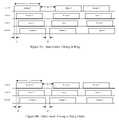
- the network nodescan be connected together in a ring or daisy chain topology with successive data frames sent in alternating directions through the bi-directional links.
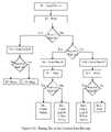
- a network that is initially configured as a ringcan re-configure to a daisy chain when a communication link or network node fails. Nodes adjacent to a faulty link or node can determine that a failure exists and trigger the network to re-configure. When the failing link or node recovers, the network can detect the change and revert back to the ring configuration.
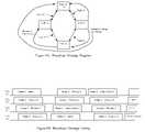
- the timing mastersends a data frame from a first port, which travels around the ring and returns to the second port of the timing master. After the complete data frame has been received, the timing master sends a next data frame from the second port. This data frame travels back around the ring to the first port of the timing master. After the first port receives the entire data frame, the process repeats for successive data frames. Thus, successive data frames bounce back and forth between “end points” of the ring, which in a ring is preferably a single timing master node.
- the inventionprovides a system comprising: a plurality of network nodes, each having at least two bi-directional ports capable of transmitting and receiving data frames; a plurality of bi-directional communication links connecting said plurality of network nodes in a physical topology which includes a serially-connected string of said network nodes; wherein said plurality of network nodes are configured to communicate successive data frames alternately in opposite directions from node to node along the string.
- FIGS. 1A and 1Bare network diagrams of a ring network with no faults and of the resulting daisy chain network when a communication link in a ring fails.
- FIG. 4is an exemplary data frame format.
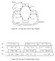
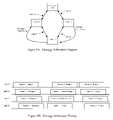
- FIGS. 7A and 7Billustrate an example of how nodes can arbitrate for network bandwidth.
- FIGS. 8A and 8Billustrate an example of low and high priority messages communicated at the same time.
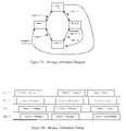
- FIGS. 10A and 10Billustrate an example of how nodes can be assigned addresses based on location in a ring.
- the network timing masteris preferably specified by the user or can be automatically determined.
- the mastermay require more resources such as memory or processor speed than other nodes, so to reduce system cost only one or two nodes need be capable of being a timing master.
- a variety of mechanisms to automatically determine the timing mastercan be used, including each node capable of being a master generating a random number and the node with the highest number becomes the timing master. Once a timing master has been determined, this information could be stored in non-volatile memory.
- the optical data sent through the POFis preferably encoded and/or scrambled in such a way to produce a sufficiently high transition density for the DPLL 42 to lock to.
- a variety of coding schemesincluding the well known biphase, miller, 4b5b, or 8b10b coding, or the proprietary DC adaptive (DCA) coding for MOST® networks could be used.
- the data framepreferably begins with a high transition density sequence or code that the DPLL can lock quickly to.
- the DPLLpreferably has a relatively high bandwidth produced by a relatively large proportional coefficient to lock quickly to the start code.
- the DPLLalso preferably has a relatively small integral coefficient to minimize phase drift during times when not data is being received.
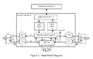
- the transmit buffer 43 and receive buffer 44are preferably FIFO memories that contain one or more messages to be sent or have been received.
- the FIFO memoriesare preferably implemented using random access memory (RAM) and read and write pointers, although other types of FIFO memories may also be used.
- the information preferably stored in RAMincludes the message length, the address, and the message data.
- the first data that the application interface writes to the transmit buffer 43 and reads from the receive buffer 44is the message length.
- the first data that the network interface logic 41 reads from the transmit buffer 43 and writes to the receive bufferis the message length.
- the RAMsare read or written a number of times equal to the value of “length” to transfer a complete message between blocks.
- the application interface logic 45allows an application processor 36 to access the transmit buffer 43 and receive buffer 44 , and to configure and manage the network controller 30 .
- the application interface logic 45can be a simple memory mapped parallel interface that includes a memory address, memory data, and read and write signals, or it could be complete microcontroller that provides a smart interface between the application and the network, or any number of other suitable structures.
- the application processor 36is typically a microcontroller that is performing some function, such as controlling a motor, and managing the interface between that function and other nodes and functions in the network.
- Some network related tasks that the application processor 36 may doinclude discovering the network address of the human machine interface (HMI) that is controlling the motor and helping the HMI discover the motor node's network address.
- Othersmay include managing the network interface controller 30 , buffering additional transmit and receive messages, and performing diagnostics.
- HMIhuman machine interface
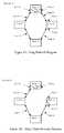
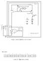
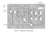
- the LED driver 37includes a current mirror made from p-channel devices 63 and 64 .
- P-channel devices 53 and 57 in conjunction with inverter 65 and control signal 58allow the LED driver 37 to be turned on and off.
- the transmit data signal 52is low, the current from current source 54 is mirrored through device 64 to device 63 to produce the current through LED 50 .
- the n-channel switch 56is conducting and the sum of the current from current sources 54 and 55 is mirrored to the LED 50 .
- the ratio of the currents from current sources 55 and 54is preferably about 10 to 1 respectively to produce roughly a 10 dB extinction ratio in the transmitted light.
- FIG. 4illustrates an exemplary data frame format that includes a start field 71 , message status field (i.e., “acknowledge field”) 72 , arbitration field 73 , message length field 74 , address field 75 , message data field 76 , and a CRC checksum field 77 .
- the start field 71provides a sequence to a receiving node that allows the receiver 38 to stabilize, the DPLL 42 to phase lock, and the network interface logic 41 to synchronize.
- the start field 71preferably includes a series of alternating ones and zeros that is long enough for LED 50 low pass filter to reach its dc operating point and for the phase of the recovered clock signal 48 to move in phase with received data transitions. The length of the start series depends on the receiver 38 architecture and parameters, and the DPLL bandwidth.
- the start fieldpreferably ends with a certain pattern that the network interface logic 41 can identify and synchronize to (i.e., a “frame alignment” marker or pattern).
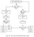
- the node wins arbitrationinserts the priority symbol of the message to be sent into the arbitration field 73 , and sends the new message (thus preempting the received message). If both MSBs are zero, the receiving node continues to compare the next sets of bits until they do not match.
- a hierarchical networkcan be formed by bridges between the ring or daisy chain networks. Such bridges preferably contain two network controllers and four ports to connect to two ring or daisy chain networks. More network controllers with more ports can bridge to more networks.
- a hierarchical networkhas one root timing master connected to nodes in the root network. If one of the nodes in the root network is a bridge to a subnet, the second network controller is the timing master for the subnet. Subnets could have attached bridges to further subnets.
- the delay through the POFis 75 nsec.
- the driver delay in the timing master 11 and the LED receiver and data recovery delay in node 12total roughly one bit period or 1 microsecond.
- the network interface logic 41preferably manages the acknowledge 72 and arbitration 73 fields on a per bit basis, and provided a high speed clock is available, the delay is preferably short, such as 25 nsec. The total delay for T 2 could then be 1.1 microseconds.
- the times T 1 through T 4 and the explanations associated with themare just one example of many possibilities.
- the data frame bit length and bit ratecan be substantially different, which can change T 1 dramatically.
- the propagation delay through the communication linkcould be substantially different if for instance the communication link was miles of long haul glass fiber or short interconnect on a printed circuit board.
- the delay through the network interface logic 41could be substantially different if different priority or acknowledge schemes are used, which could change T 2 significantly.
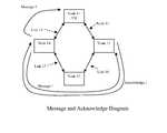
- node 14initially sends the message to node 12 in the wrong direction, which is unnecessary. Every node can learn from the direction of an acknowledgement the direction of every node in the ring or daisy chain and only send future messages in the proper direction.
- FIG. 6is just an example of different possible message transfer timing. In particular, acknowledging receipt of a message can be done at a higher level in the protocol stack.
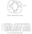
- FIG. 7Aillustrates an example of arbitration between a high priority and low priority message.
- Node 12is trying to send a high priority message 2 to node 13 while timing master 11 is trying to send a low priority message 1 in the clockwise direction to node 14 .
- FIG. 7Billustrates possible data frame and message timing for the example in FIG. 7A .
- timing master 11sends message 1 to node 12 through communication link 15 .
- Node 12replaces message 1 with its higher priority message 2 in data frame 0 and forwards to node 13 through communication link 16 .
- Node 13receives message 2 properly and can forward message 2 to nodes 14 and 11 through communication links 17 and 18 , respectively.
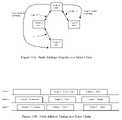
- FIG. 12Ais an illustration of an exemplary hierarchical network with root net 100 , layer 1 subnets 101 and 102 , and layer 2 subnets 110 , 111 , 112 , and 113 .
- the root net 100is connected to the layer 1 subnets 101 and 102 through bridge nodes 120 and 114 respectively.
- the layer 1 subnet 101is connected is connected to the layer 2 subnets 110 and 110 through bridge nodes 121 and 122 respectively.
- the layer 1 subnet 102is connected to the layer 2 subnets 112 and 113 through bridge nodes 123 and 124 , respectively.
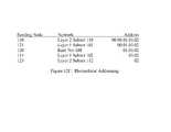
- FIG. 12Cillustrates an exemplary addressing scheme for messages passing through the hierarchy.
- the exampleshows the address field 75 of the data frames comprising a message sent from node 130 in layer 2 subnet 110 to node 131 in layer 2 subnet 112 .
- the addressing scheme shownuses node location addressing, but could have used assigned addressing.
- the location addresses for all nodesare illustrated in FIG. 12A , and show that the address path from node 130 to 131 is through bridge node 121 with address 0x00, bridge node 120 with address 0x00, bridge node 114 with address 0x01, bridge node 123 with address 0x03 and finally to node 131 with address 0x02.
- a link or nodefails, then the timing master does not receive a data frame sent from one port back on the other port.
- the timing masterknows something failed and can reinitialize the network (e.g., per the start up state machines described above). If necessary, the timing master could stop transmitting data frames once it determines there has been a fault. All other nodes could detect no incoming data frames for some period of time and shutdown. The timing master could then re-start the network according to the start up state machine.
- startup and re-initialization proceduresare just examples of many possible procedures. Other techniques may also be utilized. For example, a node could request a network re-start or re-configuration by inserting a special ACK symbol into a data frame, which is eventually received by the timing master and which then initiates a startup procedure.
Landscapes
- Engineering & Computer Science (AREA)
- Computer Networks & Wireless Communication (AREA)
- Signal Processing (AREA)
- Small-Scale Networks (AREA)
- Quality & Reliability (AREA)
- Optical Communication System (AREA)
Abstract
Description
Claims (21)
Priority Applications (21)
| Application Number | Priority Date | Filing Date | Title |
|---|---|---|---|
| US12/360,467US8179787B2 (en) | 2009-01-27 | 2009-01-27 | Fault tolerant network utilizing bi-directional point-to-point communications links between nodes |
| JP2011547972AJP5351285B2 (en) | 2009-01-27 | 2010-01-26 | Method for use with a network node within an interconnected network of nodes |
| EP10746522.1AEP2392104A4 (en) | 2009-01-27 | 2010-01-26 | Fault tolerant network utilizing bi-directional point-to-point communications links between nodes |
| KR1020117019985AKR20110126641A (en) | 2009-01-27 | 2010-01-26 | Fault-tolerant network with bidirectional point-to-point communication link between nodes |
| PCT/US2010/000219WO2010098811A2 (en) | 2009-01-27 | 2010-01-26 | Fault tolerant network utilizing bi-directional point-to-point communications links between nodes |
| US12/803,805US9509525B2 (en) | 2008-09-05 | 2010-07-07 | Intelligent illumination device |
| US12/806,121US8471496B2 (en) | 2008-09-05 | 2010-08-05 | LED calibration systems and related methods |
| US12/806,114US20110063214A1 (en) | 2008-09-05 | 2010-08-05 | Display and optical pointer systems and related methods |
| US12/806,126US8521035B2 (en) | 2008-09-05 | 2010-08-05 | Systems and methods for visible light communication |
| US12/806,117US9276766B2 (en) | 2008-09-05 | 2010-08-05 | Display calibration systems and related methods |
| US12/806,118US8773336B2 (en) | 2008-09-05 | 2010-08-05 | Illumination devices and related systems and methods |
| US12/806,113US8456092B2 (en) | 2008-09-05 | 2010-08-05 | Broad spectrum light source calibration systems and related methods |
| US12/924,628US8674913B2 (en) | 2008-09-05 | 2010-09-30 | LED transceiver front end circuitry and related methods |
| US13/451,908US20120201126A1 (en) | 2009-01-27 | 2012-04-20 | Fault Tolerant Network Utilizing Bi-Directional Point-to-Point Communications Links Between Nodes |
| JP2013118775AJP5600773B2 (en) | 2009-01-27 | 2013-06-05 | System and information communication method |
| JP2013118780AJP5714649B2 (en) | 2009-01-27 | 2013-06-05 | Physical layer interface, system and method |
| US14/305,472US9295112B2 (en) | 2008-09-05 | 2014-06-16 | Illumination devices and related systems and methods |
| US14/305,456US20150022098A1 (en) | 2008-09-05 | 2014-06-16 | Illumination Devices and Related Systems and Methods |
| US15/296,258US9848482B2 (en) | 2008-09-05 | 2016-10-18 | Intelligent illumination device |
| US15/953,202US10847026B2 (en) | 2008-09-05 | 2018-04-13 | Visible light communication system and method |
| US16/721,214USRE50468E1 (en) | 2008-09-05 | 2019-12-19 | Intelligent illumination device |
Applications Claiming Priority (1)
| Application Number | Priority Date | Filing Date | Title |
|---|---|---|---|
| US12/360,467US8179787B2 (en) | 2009-01-27 | 2009-01-27 | Fault tolerant network utilizing bi-directional point-to-point communications links between nodes |
Related Parent Applications (1)
| Application Number | Title | Priority Date | Filing Date |
|---|---|---|---|
| US12/584,143Continuation-In-PartUS8886047B2 (en) | 2008-09-05 | 2009-09-01 | Optical communication device, method and system |
Related Child Applications (4)
| Application Number | Title | Priority Date | Filing Date |
|---|---|---|---|
| US12/584,143Continuation-In-PartUS8886047B2 (en) | 2008-09-05 | 2009-09-01 | Optical communication device, method and system |
| US12/803,805Continuation-In-PartUS9509525B2 (en) | 2008-09-05 | 2010-07-07 | Intelligent illumination device |
| US12/924,628Continuation-In-PartUS8674913B2 (en) | 2008-09-05 | 2010-09-30 | LED transceiver front end circuitry and related methods |
| US13/451,908DivisionUS20120201126A1 (en) | 2009-01-27 | 2012-04-20 | Fault Tolerant Network Utilizing Bi-Directional Point-to-Point Communications Links Between Nodes |
Publications (2)
| Publication Number | Publication Date |
|---|---|
| US20100188972A1 US20100188972A1 (en) | 2010-07-29 |
| US8179787B2true US8179787B2 (en) | 2012-05-15 |
Family
ID=42354069
Family Applications (2)
| Application Number | Title | Priority Date | Filing Date |
|---|---|---|---|
| US12/360,467Active2030-02-16US8179787B2 (en) | 2008-09-05 | 2009-01-27 | Fault tolerant network utilizing bi-directional point-to-point communications links between nodes |
| US13/451,908AbandonedUS20120201126A1 (en) | 2009-01-27 | 2012-04-20 | Fault Tolerant Network Utilizing Bi-Directional Point-to-Point Communications Links Between Nodes |
Family Applications After (1)
| Application Number | Title | Priority Date | Filing Date |
|---|---|---|---|
| US13/451,908AbandonedUS20120201126A1 (en) | 2009-01-27 | 2012-04-20 | Fault Tolerant Network Utilizing Bi-Directional Point-to-Point Communications Links Between Nodes |
Country Status (5)
| Country | Link |
|---|---|
| US (2) | US8179787B2 (en) |
| EP (1) | EP2392104A4 (en) |
| JP (3) | JP5351285B2 (en) |
| KR (1) | KR20110126641A (en) |
| WO (1) | WO2010098811A2 (en) |
Cited By (158)
| Publication number | Priority date | Publication date | Assignee | Title |
|---|---|---|---|---|
| US20090300399A1 (en)* | 2008-05-29 | 2009-12-03 | International Business Machines Corporation | Profiling power consumption of a plurality of compute nodes while processing an application |
| US20090300386A1 (en)* | 2008-05-29 | 2009-12-03 | International Business Machines Corporation | Reducing power consumption during execution of an application on a plurality of compute nodes |
| US20110267197A1 (en)* | 2010-04-29 | 2011-11-03 | International Business Machines Corporation | Monitoring Operating Parameters In A Distributed Computing System With Active Messages |
| US20120201126A1 (en)* | 2009-01-27 | 2012-08-09 | Smsc Holdings S.A.R.L. | Fault Tolerant Network Utilizing Bi-Directional Point-to-Point Communications Links Between Nodes |
| US8458722B2 (en) | 2008-06-09 | 2013-06-04 | International Business Machines Corporation | Thread selection according to predefined power characteristics during context switching on compute nodes |
| US8539270B2 (en) | 2008-07-03 | 2013-09-17 | International Business Machines Corporation | Profiling an application for power consumption during execution on a compute node |
| US20130258906A1 (en)* | 2012-03-29 | 2013-10-03 | Robert Bosch Gmbh | Communication configuration and method for debugging, respectively for programming one or more participants of the communication configuration |
| US20140064740A1 (en)* | 2012-09-06 | 2014-03-06 | Korea Electronics Technology Institute | Vehicle communication system for visible light communication and optical networking and communication method thereof |
| US20150235528A1 (en)* | 2012-05-03 | 2015-08-20 | Abl Ip Holding Llc | Lighting device and apparatus with multiple applications for processing a common sensed condition |
| US20150358178A1 (en)* | 2013-02-15 | 2015-12-10 | Thales | Data transmission architecture, in particular for use in on-board avionics |
| US9538617B2 (en) | 2012-08-01 | 2017-01-03 | Abl Ip Holding Llc | Networked system of intelligent lighting devices with sharing of processing resources of the devices with other entities |
| US9608740B2 (en) | 2015-07-15 | 2017-03-28 | At&T Intellectual Property I, L.P. | Method and apparatus for launching a wave mode that mitigates interference |
| US9615269B2 (en) | 2014-10-02 | 2017-04-04 | At&T Intellectual Property I, L.P. | Method and apparatus that provides fault tolerance in a communication network |
| US9640850B2 (en) | 2015-06-25 | 2017-05-02 | At&T Intellectual Property I, L.P. | Methods and apparatus for inducing a non-fundamental wave mode on a transmission medium |
| US9667317B2 (en) | 2015-06-15 | 2017-05-30 | At&T Intellectual Property I, L.P. | Method and apparatus for providing security using network traffic adjustments |
| US9674711B2 (en) | 2013-11-06 | 2017-06-06 | At&T Intellectual Property I, L.P. | Surface-wave communications and methods thereof |
| US9685992B2 (en) | 2014-10-03 | 2017-06-20 | At&T Intellectual Property I, L.P. | Circuit panel network and methods thereof |
| US9705610B2 (en) | 2014-10-21 | 2017-07-11 | At&T Intellectual Property I, L.P. | Transmission device with impairment compensation and methods for use therewith |
| US9705561B2 (en) | 2015-04-24 | 2017-07-11 | At&T Intellectual Property I, L.P. | Directional coupling device and methods for use therewith |
| US9722318B2 (en) | 2015-07-14 | 2017-08-01 | At&T Intellectual Property I, L.P. | Method and apparatus for coupling an antenna to a device |
| US9729197B2 (en) | 2015-10-01 | 2017-08-08 | At&T Intellectual Property I, L.P. | Method and apparatus for communicating network management traffic over a network |
| US9735833B2 (en) | 2015-07-31 | 2017-08-15 | At&T Intellectual Property I, L.P. | Method and apparatus for communications management in a neighborhood network |
| US9742462B2 (en) | 2014-12-04 | 2017-08-22 | At&T Intellectual Property I, L.P. | Transmission medium and communication interfaces and methods for use therewith |
| US9742521B2 (en) | 2014-11-20 | 2017-08-22 | At&T Intellectual Property I, L.P. | Transmission device with mode division multiplexing and methods for use therewith |
| US9749053B2 (en) | 2015-07-23 | 2017-08-29 | At&T Intellectual Property I, L.P. | Node device, repeater and methods for use therewith |
| US9748626B2 (en) | 2015-05-14 | 2017-08-29 | At&T Intellectual Property I, L.P. | Plurality of cables having different cross-sectional shapes which are bundled together to form a transmission medium |
| US9749013B2 (en) | 2015-03-17 | 2017-08-29 | At&T Intellectual Property I, L.P. | Method and apparatus for reducing attenuation of electromagnetic waves guided by a transmission medium |
| US9762289B2 (en) | 2014-10-14 | 2017-09-12 | At&T Intellectual Property I, L.P. | Method and apparatus for transmitting or receiving signals in a transportation system |
| US9768833B2 (en) | 2014-09-15 | 2017-09-19 | At&T Intellectual Property I, L.P. | Method and apparatus for sensing a condition in a transmission medium of electromagnetic waves |
| US9769020B2 (en) | 2014-10-21 | 2017-09-19 | At&T Intellectual Property I, L.P. | Method and apparatus for responding to events affecting communications in a communication network |
| US9769128B2 (en) | 2015-09-28 | 2017-09-19 | At&T Intellectual Property I, L.P. | Method and apparatus for encryption of communications over a network |
| US9780834B2 (en) | 2014-10-21 | 2017-10-03 | At&T Intellectual Property I, L.P. | Method and apparatus for transmitting electromagnetic waves |
| US9787412B2 (en) | 2015-06-25 | 2017-10-10 | At&T Intellectual Property I, L.P. | Methods and apparatus for inducing a fundamental wave mode on a transmission medium |
| US9788326B2 (en) | 2012-12-05 | 2017-10-10 | At&T Intellectual Property I, L.P. | Backhaul link for distributed antenna system |
| US9793951B2 (en) | 2015-07-15 | 2017-10-17 | At&T Intellectual Property I, L.P. | Method and apparatus for launching a wave mode that mitigates interference |
| US9793954B2 (en) | 2015-04-28 | 2017-10-17 | At&T Intellectual Property I, L.P. | Magnetic coupling device and methods for use therewith |
| US9793955B2 (en) | 2015-04-24 | 2017-10-17 | At&T Intellectual Property I, Lp | Passive electrical coupling device and methods for use therewith |
| US9800327B2 (en) | 2014-11-20 | 2017-10-24 | At&T Intellectual Property I, L.P. | Apparatus for controlling operations of a communication device and methods thereof |
| US9820146B2 (en) | 2015-06-12 | 2017-11-14 | At&T Intellectual Property I, L.P. | Method and apparatus for authentication and identity management of communicating devices |
| US9838078B2 (en) | 2015-07-31 | 2017-12-05 | At&T Intellectual Property I, L.P. | Method and apparatus for exchanging communication signals |
| US9838896B1 (en) | 2016-12-09 | 2017-12-05 | At&T Intellectual Property I, L.P. | Method and apparatus for assessing network coverage |
| US9847566B2 (en) | 2015-07-14 | 2017-12-19 | At&T Intellectual Property I, L.P. | Method and apparatus for adjusting a field of a signal to mitigate interference |
| US9847850B2 (en) | 2014-10-14 | 2017-12-19 | At&T Intellectual Property I, L.P. | Method and apparatus for adjusting a mode of communication in a communication network |
| US9853342B2 (en) | 2015-07-14 | 2017-12-26 | At&T Intellectual Property I, L.P. | Dielectric transmission medium connector and methods for use therewith |
| US9860075B1 (en) | 2016-08-26 | 2018-01-02 | At&T Intellectual Property I, L.P. | Method and communication node for broadband distribution |
| US9866309B2 (en) | 2015-06-03 | 2018-01-09 | At&T Intellectual Property I, Lp | Host node device and methods for use therewith |
| US9865911B2 (en) | 2015-06-25 | 2018-01-09 | At&T Intellectual Property I, L.P. | Waveguide system for slot radiating first electromagnetic waves that are combined into a non-fundamental wave mode second electromagnetic wave on a transmission medium |
| US9866276B2 (en) | 2014-10-10 | 2018-01-09 | At&T Intellectual Property I, L.P. | Method and apparatus for arranging communication sessions in a communication system |
| US9871558B2 (en) | 2014-10-21 | 2018-01-16 | At&T Intellectual Property I, L.P. | Guided-wave transmission device and methods for use therewith |
| US9871282B2 (en) | 2015-05-14 | 2018-01-16 | At&T Intellectual Property I, L.P. | At least one transmission medium having a dielectric surface that is covered at least in part by a second dielectric |
| US9871283B2 (en) | 2015-07-23 | 2018-01-16 | At&T Intellectual Property I, Lp | Transmission medium having a dielectric core comprised of plural members connected by a ball and socket configuration |
| US9876571B2 (en) | 2015-02-20 | 2018-01-23 | At&T Intellectual Property I, Lp | Guided-wave transmission device with non-fundamental mode propagation and methods for use therewith |
| US9876605B1 (en) | 2016-10-21 | 2018-01-23 | At&T Intellectual Property I, L.P. | Launcher and coupling system to support desired guided wave mode |
| US9876264B2 (en) | 2015-10-02 | 2018-01-23 | At&T Intellectual Property I, Lp | Communication system, guided wave switch and methods for use therewith |
| US9882257B2 (en) | 2015-07-14 | 2018-01-30 | At&T Intellectual Property I, L.P. | Method and apparatus for launching a wave mode that mitigates interference |
| US9887447B2 (en) | 2015-05-14 | 2018-02-06 | At&T Intellectual Property I, L.P. | Transmission medium having multiple cores and methods for use therewith |
| US9893795B1 (en) | 2016-12-07 | 2018-02-13 | At&T Intellectual Property I, Lp | Method and repeater for broadband distribution |
| US9906269B2 (en) | 2014-09-17 | 2018-02-27 | At&T Intellectual Property I, L.P. | Monitoring and mitigating conditions in a communication network |
| US9904535B2 (en) | 2015-09-14 | 2018-02-27 | At&T Intellectual Property I, L.P. | Method and apparatus for distributing software |
| US9912033B2 (en) | 2014-10-21 | 2018-03-06 | At&T Intellectual Property I, Lp | Guided wave coupler, coupling module and methods for use therewith |
| US9912382B2 (en) | 2015-06-03 | 2018-03-06 | At&T Intellectual Property I, Lp | Network termination and methods for use therewith |
| US9913139B2 (en) | 2015-06-09 | 2018-03-06 | At&T Intellectual Property I, L.P. | Signal fingerprinting for authentication of communicating devices |
| US9912419B1 (en) | 2016-08-24 | 2018-03-06 | At&T Intellectual Property I, L.P. | Method and apparatus for managing a fault in a distributed antenna system |
| US9912027B2 (en) | 2015-07-23 | 2018-03-06 | At&T Intellectual Property I, L.P. | Method and apparatus for exchanging communication signals |
| US9911020B1 (en) | 2016-12-08 | 2018-03-06 | At&T Intellectual Property I, L.P. | Method and apparatus for tracking via a radio frequency identification device |
| US9917341B2 (en) | 2015-05-27 | 2018-03-13 | At&T Intellectual Property I, L.P. | Apparatus and method for launching electromagnetic waves and for modifying radial dimensions of the propagating electromagnetic waves |
| US9929755B2 (en) | 2015-07-14 | 2018-03-27 | At&T Intellectual Property I, L.P. | Method and apparatus for coupling an antenna to a device |
| US9930668B2 (en) | 2013-05-31 | 2018-03-27 | At&T Intellectual Property I, L.P. | Remote distributed antenna system |
| US9927517B1 (en) | 2016-12-06 | 2018-03-27 | At&T Intellectual Property I, L.P. | Apparatus and methods for sensing rainfall |
| US9948355B2 (en) | 2014-10-21 | 2018-04-17 | At&T Intellectual Property I, L.P. | Apparatus for providing communication services and methods thereof |
| US9948354B2 (en) | 2015-04-28 | 2018-04-17 | At&T Intellectual Property I, L.P. | Magnetic coupling device with reflective plate and methods for use therewith |
| US9948333B2 (en) | 2015-07-23 | 2018-04-17 | At&T Intellectual Property I, L.P. | Method and apparatus for wireless communications to mitigate interference |
| US9954287B2 (en) | 2014-11-20 | 2018-04-24 | At&T Intellectual Property I, L.P. | Apparatus for converting wireless signals and electromagnetic waves and methods thereof |
| US9954286B2 (en) | 2014-10-21 | 2018-04-24 | At&T Intellectual Property I, L.P. | Guided-wave transmission device with non-fundamental mode propagation and methods for use therewith |
| US9967173B2 (en) | 2015-07-31 | 2018-05-08 | At&T Intellectual Property I, L.P. | Method and apparatus for authentication and identity management of communicating devices |
| US9973940B1 (en) | 2017-02-27 | 2018-05-15 | At&T Intellectual Property I, L.P. | Apparatus and methods for dynamic impedance matching of a guided wave launcher |
| US9991580B2 (en) | 2016-10-21 | 2018-06-05 | At&T Intellectual Property I, L.P. | Launcher and coupling system for guided wave mode cancellation |
| US9999038B2 (en) | 2013-05-31 | 2018-06-12 | At&T Intellectual Property I, L.P. | Remote distributed antenna system |
| US9998870B1 (en) | 2016-12-08 | 2018-06-12 | At&T Intellectual Property I, L.P. | Method and apparatus for proximity sensing |
| US9997819B2 (en) | 2015-06-09 | 2018-06-12 | At&T Intellectual Property I, L.P. | Transmission medium and method for facilitating propagation of electromagnetic waves via a core |
| US10009063B2 (en) | 2015-09-16 | 2018-06-26 | At&T Intellectual Property I, L.P. | Method and apparatus for use with a radio distributed antenna system having an out-of-band reference signal |
| US10009067B2 (en) | 2014-12-04 | 2018-06-26 | At&T Intellectual Property I, L.P. | Method and apparatus for configuring a communication interface |
| US10020844B2 (en) | 2016-12-06 | 2018-07-10 | T&T Intellectual Property I, L.P. | Method and apparatus for broadcast communication via guided waves |
| US10027509B2 (en) | 2013-02-15 | 2018-07-17 | Thales | Bridge-based data transmission architecture, in particular for use in on-board avionics |
| US10027398B2 (en) | 2015-06-11 | 2018-07-17 | At&T Intellectual Property I, Lp | Repeater and methods for use therewith |
| US10027397B2 (en) | 2016-12-07 | 2018-07-17 | At&T Intellectual Property I, L.P. | Distributed antenna system and methods for use therewith |
| US10033108B2 (en) | 2015-07-14 | 2018-07-24 | At&T Intellectual Property I, L.P. | Apparatus and methods for generating an electromagnetic wave having a wave mode that mitigates interference |
| US10044409B2 (en) | 2015-07-14 | 2018-08-07 | At&T Intellectual Property I, L.P. | Transmission medium and methods for use therewith |
| US10069535B2 (en) | 2016-12-08 | 2018-09-04 | At&T Intellectual Property I, L.P. | Apparatus and methods for launching electromagnetic waves having a certain electric field structure |
| US10079661B2 (en) | 2015-09-16 | 2018-09-18 | At&T Intellectual Property I, L.P. | Method and apparatus for use with a radio distributed antenna system having a clock reference |
| US10090606B2 (en) | 2015-07-15 | 2018-10-02 | At&T Intellectual Property I, L.P. | Antenna system with dielectric array and methods for use therewith |
| US10090594B2 (en) | 2016-11-23 | 2018-10-02 | At&T Intellectual Property I, L.P. | Antenna system having structural configurations for assembly |
| US10103422B2 (en) | 2016-12-08 | 2018-10-16 | At&T Intellectual Property I, L.P. | Method and apparatus for mounting network devices |
| US10103801B2 (en) | 2015-06-03 | 2018-10-16 | At&T Intellectual Property I, L.P. | Host node device and methods for use therewith |
| US10112606B2 (en) | 2016-01-22 | 2018-10-30 | International Business Machines Corporation | Scalable sensor fusion and autonomous x-by-wire control |
| US10135147B2 (en) | 2016-10-18 | 2018-11-20 | At&T Intellectual Property I, L.P. | Apparatus and methods for launching guided waves via an antenna |
| US10135146B2 (en) | 2016-10-18 | 2018-11-20 | At&T Intellectual Property I, L.P. | Apparatus and methods for launching guided waves via circuits |
| US10136434B2 (en) | 2015-09-16 | 2018-11-20 | At&T Intellectual Property I, L.P. | Method and apparatus for use with a radio distributed antenna system having an ultra-wideband control channel |
| US10135145B2 (en) | 2016-12-06 | 2018-11-20 | At&T Intellectual Property I, L.P. | Apparatus and methods for generating an electromagnetic wave along a transmission medium |
| US10139820B2 (en) | 2016-12-07 | 2018-11-27 | At&T Intellectual Property I, L.P. | Method and apparatus for deploying equipment of a communication system |
| US10144036B2 (en) | 2015-01-30 | 2018-12-04 | At&T Intellectual Property I, L.P. | Method and apparatus for mitigating interference affecting a propagation of electromagnetic waves guided by a transmission medium |
| US10148016B2 (en) | 2015-07-14 | 2018-12-04 | At&T Intellectual Property I, L.P. | Apparatus and methods for communicating utilizing an antenna array |
| US10170840B2 (en) | 2015-07-14 | 2019-01-01 | At&T Intellectual Property I, L.P. | Apparatus and methods for sending or receiving electromagnetic signals |
| US10168695B2 (en) | 2016-12-07 | 2019-01-01 | At&T Intellectual Property I, L.P. | Method and apparatus for controlling an unmanned aircraft |
| US10178445B2 (en) | 2016-11-23 | 2019-01-08 | At&T Intellectual Property I, L.P. | Methods, devices, and systems for load balancing between a plurality of waveguides |
| US10205655B2 (en) | 2015-07-14 | 2019-02-12 | At&T Intellectual Property I, L.P. | Apparatus and methods for communicating utilizing an antenna array and multiple communication paths |
| US10225025B2 (en) | 2016-11-03 | 2019-03-05 | At&T Intellectual Property I, L.P. | Method and apparatus for detecting a fault in a communication system |
| US10224634B2 (en) | 2016-11-03 | 2019-03-05 | At&T Intellectual Property I, L.P. | Methods and apparatus for adjusting an operational characteristic of an antenna |
| US10243270B2 (en) | 2016-12-07 | 2019-03-26 | At&T Intellectual Property I, L.P. | Beam adaptive multi-feed dielectric antenna system and methods for use therewith |
| US10243784B2 (en) | 2014-11-20 | 2019-03-26 | At&T Intellectual Property I, L.P. | System for generating topology information and methods thereof |
| US10264586B2 (en) | 2016-12-09 | 2019-04-16 | At&T Mobility Ii Llc | Cloud-based packet controller and methods for use therewith |
| US10291334B2 (en) | 2016-11-03 | 2019-05-14 | At&T Intellectual Property I, L.P. | System for detecting a fault in a communication system |
| US10291311B2 (en) | 2016-09-09 | 2019-05-14 | At&T Intellectual Property I, L.P. | Method and apparatus for mitigating a fault in a distributed antenna system |
| US10298293B2 (en) | 2017-03-13 | 2019-05-21 | At&T Intellectual Property I, L.P. | Apparatus of communication utilizing wireless network devices |
| US10305190B2 (en) | 2016-12-01 | 2019-05-28 | At&T Intellectual Property I, L.P. | Reflecting dielectric antenna system and methods for use therewith |
| US10312567B2 (en) | 2016-10-26 | 2019-06-04 | At&T Intellectual Property I, L.P. | Launcher with planar strip antenna and methods for use therewith |
| US10320586B2 (en) | 2015-07-14 | 2019-06-11 | At&T Intellectual Property I, L.P. | Apparatus and methods for generating non-interfering electromagnetic waves on an insulated transmission medium |
| US10326689B2 (en) | 2016-12-08 | 2019-06-18 | At&T Intellectual Property I, L.P. | Method and system for providing alternative communication paths |
| US10326494B2 (en) | 2016-12-06 | 2019-06-18 | At&T Intellectual Property I, L.P. | Apparatus for measurement de-embedding and methods for use therewith |
| US10340573B2 (en) | 2016-10-26 | 2019-07-02 | At&T Intellectual Property I, L.P. | Launcher with cylindrical coupling device and methods for use therewith |
| US10341142B2 (en) | 2015-07-14 | 2019-07-02 | At&T Intellectual Property I, L.P. | Apparatus and methods for generating non-interfering electromagnetic waves on an uninsulated conductor |
| US10340983B2 (en) | 2016-12-09 | 2019-07-02 | At&T Intellectual Property I, L.P. | Method and apparatus for surveying remote sites via guided wave communications |
| US10340603B2 (en) | 2016-11-23 | 2019-07-02 | At&T Intellectual Property I, L.P. | Antenna system having shielded structural configurations for assembly |
| US10340601B2 (en) | 2016-11-23 | 2019-07-02 | At&T Intellectual Property I, L.P. | Multi-antenna system and methods for use therewith |
| US10340600B2 (en) | 2016-10-18 | 2019-07-02 | At&T Intellectual Property I, L.P. | Apparatus and methods for launching guided waves via plural waveguide systems |
| US10355367B2 (en) | 2015-10-16 | 2019-07-16 | At&T Intellectual Property I, L.P. | Antenna structure for exchanging wireless signals |
| US10361489B2 (en) | 2016-12-01 | 2019-07-23 | At&T Intellectual Property I, L.P. | Dielectric dish antenna system and methods for use therewith |
| US10359749B2 (en) | 2016-12-07 | 2019-07-23 | At&T Intellectual Property I, L.P. | Method and apparatus for utilities management via guided wave communication |
| US10374316B2 (en) | 2016-10-21 | 2019-08-06 | At&T Intellectual Property I, L.P. | System and dielectric antenna with non-uniform dielectric |
| US10382976B2 (en) | 2016-12-06 | 2019-08-13 | At&T Intellectual Property I, L.P. | Method and apparatus for managing wireless communications based on communication paths and network device positions |
| US10389037B2 (en) | 2016-12-08 | 2019-08-20 | At&T Intellectual Property I, L.P. | Apparatus and methods for selecting sections of an antenna array and use therewith |
| US10389029B2 (en) | 2016-12-07 | 2019-08-20 | At&T Intellectual Property I, L.P. | Multi-feed dielectric antenna system with core selection and methods for use therewith |
| US10411356B2 (en) | 2016-12-08 | 2019-09-10 | At&T Intellectual Property I, L.P. | Apparatus and methods for selectively targeting communication devices with an antenna array |
| US10439675B2 (en) | 2016-12-06 | 2019-10-08 | At&T Intellectual Property I, L.P. | Method and apparatus for repeating guided wave communication signals |
| US10446936B2 (en) | 2016-12-07 | 2019-10-15 | At&T Intellectual Property I, L.P. | Multi-feed dielectric antenna system and methods for use therewith |
| US10498044B2 (en) | 2016-11-03 | 2019-12-03 | At&T Intellectual Property I, L.P. | Apparatus for configuring a surface of an antenna |
| US10530505B2 (en) | 2016-12-08 | 2020-01-07 | At&T Intellectual Property I, L.P. | Apparatus and methods for launching electromagnetic waves along a transmission medium |
| US10535928B2 (en) | 2016-11-23 | 2020-01-14 | At&T Intellectual Property I, L.P. | Antenna system and methods for use therewith |
| US10547348B2 (en) | 2016-12-07 | 2020-01-28 | At&T Intellectual Property I, L.P. | Method and apparatus for switching transmission mediums in a communication system |
| US10601494B2 (en) | 2016-12-08 | 2020-03-24 | At&T Intellectual Property I, L.P. | Dual-band communication device and method for use therewith |
| US10637149B2 (en) | 2016-12-06 | 2020-04-28 | At&T Intellectual Property I, L.P. | Injection molded dielectric antenna and methods for use therewith |
| US10650940B2 (en) | 2015-05-15 | 2020-05-12 | At&T Intellectual Property I, L.P. | Transmission medium having a conductive material and methods for use therewith |
| US10694379B2 (en) | 2016-12-06 | 2020-06-23 | At&T Intellectual Property I, L.P. | Waveguide system with device-based authentication and methods for use therewith |
| US10727599B2 (en) | 2016-12-06 | 2020-07-28 | At&T Intellectual Property I, L.P. | Launcher with slot antenna and methods for use therewith |
| US10755542B2 (en) | 2016-12-06 | 2020-08-25 | At&T Intellectual Property I, L.P. | Method and apparatus for surveillance via guided wave communication |
| US10777873B2 (en) | 2016-12-08 | 2020-09-15 | At&T Intellectual Property I, L.P. | Method and apparatus for mounting network devices |
| US10797781B2 (en) | 2015-06-03 | 2020-10-06 | At&T Intellectual Property I, L.P. | Client node device and methods for use therewith |
| US10811767B2 (en) | 2016-10-21 | 2020-10-20 | At&T Intellectual Property I, L.P. | System and dielectric antenna with convex dielectric radome |
| US10819035B2 (en) | 2016-12-06 | 2020-10-27 | At&T Intellectual Property I, L.P. | Launcher with helical antenna and methods for use therewith |
| US10916969B2 (en) | 2016-12-08 | 2021-02-09 | At&T Intellectual Property I, L.P. | Method and apparatus for providing power using an inductive coupling |
| US10938108B2 (en) | 2016-12-08 | 2021-03-02 | At&T Intellectual Property I, L.P. | Frequency selective multi-feed dielectric antenna system and methods for use therewith |
| US11032819B2 (en) | 2016-09-15 | 2021-06-08 | At&T Intellectual Property I, L.P. | Method and apparatus for use with a radio distributed antenna system having a control channel reference signal |
| US11153956B2 (en) | 2015-08-05 | 2021-10-19 | Lutron Technology Company Llc | Commissioning and controlling load control devices |
| US11431613B2 (en) | 2020-09-02 | 2022-08-30 | Honeywell International Inc. | Compressed and efficient byzantine agreement |
| US11438225B2 (en) | 2019-03-08 | 2022-09-06 | Lutron Technology Company Llc | Commissioning and controlling load control devices |
| US11665112B2 (en) | 2020-09-02 | 2023-05-30 | Honeywell International Inc. | Self-checking node |
| US12081428B2 (en) | 2022-02-18 | 2024-09-03 | HCL America Inc. | Method and system for testbench component lock-up identification during simulation |
| US12445350B2 (en) | 2023-06-07 | 2025-10-14 | Lutron Technology Company Llc | Commissioning and controlling load control devices |
Families Citing this family (106)
| Publication number | Priority date | Publication date | Assignee | Title |
|---|---|---|---|---|
| US7734741B2 (en)* | 2004-12-13 | 2010-06-08 | Intel Corporation | Method, system, and apparatus for dynamic reconfiguration of resources |
| US7738484B2 (en)* | 2004-12-13 | 2010-06-15 | Intel Corporation | Method, system, and apparatus for system level initialization |
| US10210750B2 (en) | 2011-09-13 | 2019-02-19 | Lutron Electronics Co., Inc. | System and method of extending the communication range in a visible light communication system |
| US8456092B2 (en) | 2008-09-05 | 2013-06-04 | Ketra, Inc. | Broad spectrum light source calibration systems and related methods |
| US8471496B2 (en) | 2008-09-05 | 2013-06-25 | Ketra, Inc. | LED calibration systems and related methods |
| US8521035B2 (en)* | 2008-09-05 | 2013-08-27 | Ketra, Inc. | Systems and methods for visible light communication |
| USRE50468E1 (en) | 2008-09-05 | 2025-06-24 | Lutron Technology Company Llc | Intelligent illumination device |
| US9509525B2 (en)* | 2008-09-05 | 2016-11-29 | Ketra, Inc. | Intelligent illumination device |
| US8773336B2 (en) | 2008-09-05 | 2014-07-08 | Ketra, Inc. | Illumination devices and related systems and methods |
| WO2010027459A2 (en)* | 2008-09-05 | 2010-03-11 | Firefly Green Technologies Inc. | Optical communication device, method and system |
| US8674913B2 (en) | 2008-09-05 | 2014-03-18 | Ketra, Inc. | LED transceiver front end circuitry and related methods |
| US9276766B2 (en)* | 2008-09-05 | 2016-03-01 | Ketra, Inc. | Display calibration systems and related methods |
| DE102010031514B4 (en)* | 2009-12-17 | 2018-04-12 | Bayerische Motoren Werke Aktiengesellschaft | Transmission of data via a packet-oriented network in a vehicle |
| DE102010008818A1 (en)* | 2010-02-22 | 2011-08-25 | Continental Automotive GmbH, 30165 | Method for activating a network component of a vehicle network system |
| US9386668B2 (en) | 2010-09-30 | 2016-07-05 | Ketra, Inc. | Lighting control system |
| USRE49454E1 (en) | 2010-09-30 | 2023-03-07 | Lutron Technology Company Llc | Lighting control system |
| US20120166621A1 (en)* | 2010-12-23 | 2012-06-28 | Anish Sharma | Sharing the Status of S-CSCF Nodes Across I-CSCF Nodes in a Communications Network |
| TWI459774B (en)* | 2011-04-29 | 2014-11-01 | Ind Tech Res Inst | Asynchronous master-slave serial communication systam, data transmission method, and control module using the same thereof |
| US9681108B2 (en) | 2011-05-15 | 2017-06-13 | Lighting Science Group Corporation | Occupancy sensor and associated methods |
| US9185783B2 (en) | 2011-05-15 | 2015-11-10 | Lighting Science Group Corporation | Wireless pairing system and associated methods |
| US8729832B2 (en) | 2011-05-15 | 2014-05-20 | Lighting Science Group Corporation | Programmable luminaire system |
| US8674608B2 (en) | 2011-05-15 | 2014-03-18 | Lighting Science Group Corporation | Configurable environmental condition sensing luminaire, system and associated methods |
| US9648284B2 (en) | 2011-05-15 | 2017-05-09 | Lighting Science Group Corporation | Occupancy sensor and associated methods |
| US8749172B2 (en) | 2011-07-08 | 2014-06-10 | Ketra, Inc. | Luminance control for illumination devices |
| US8492995B2 (en) | 2011-10-07 | 2013-07-23 | Environmental Light Technologies Corp. | Wavelength sensing lighting system and associated methods |
| US8515289B2 (en) | 2011-11-21 | 2013-08-20 | Environmental Light Technologies Corp. | Wavelength sensing lighting system and associated methods for national security application |
| US9100210B2 (en)* | 2011-11-15 | 2015-08-04 | Rockwell Automation Technologies, Inc. | Redundant gateway system for device level ring networks |
| JP5987319B2 (en)* | 2012-01-06 | 2016-09-07 | 富士ゼロックス株式会社 | Transmission / reception system and program |
| US9270484B2 (en)* | 2012-01-23 | 2016-02-23 | Microsoft Technology Licensing, Llc | Data center network using circuit switching |
| CN103226208B (en)* | 2012-01-25 | 2018-02-02 | 英洛瓦(天津)物探装备有限责任公司 | It is synchronous by the clock of optical fiber |
| DE102012201669B4 (en)* | 2012-02-10 | 2021-05-06 | Robert Bosch Gmbh | Method and communication controller for data transmission between two data processing units connected by means of transmission links |
| DE102012003515A1 (en)* | 2012-02-24 | 2013-08-29 | Rheinmetall Landsysteme Gmbh | Computer network with an annular bus connection |
| US9402294B2 (en) | 2012-05-08 | 2016-07-26 | Lighting Science Group Corporation | Self-calibrating multi-directional security luminaire and associated methods |
| US9006987B2 (en) | 2012-05-07 | 2015-04-14 | Lighting Science Group, Inc. | Wall-mountable luminaire and associated systems and methods |
| EP2672637B1 (en)* | 2012-06-08 | 2018-03-14 | Knowledge Development for POF, S.L. | Frame Structure for Adaptive Data Communications over a Plastic Optical Fibre |
| DE102012210057A1 (en)* | 2012-06-14 | 2013-12-19 | Continental Automotive Gmbh | Annular network for a vehicle |
| US8861664B2 (en)* | 2012-06-15 | 2014-10-14 | Smsc Holdings S.A.R.L. | Communication system and method for synchronizing a plurality of network nodes after a network lock condition occurs |
| EP2677692B1 (en)* | 2012-06-18 | 2019-07-24 | Renesas Electronics Europe Limited | Communication controller |
| US9088514B2 (en)* | 2012-07-23 | 2015-07-21 | Broadcom Corporation | Flexray communications using ethernet |
| TW201412058A (en)* | 2012-09-07 | 2014-03-16 | Etherwan Systems Inc | Redundant system of a ring network and redundant method thereof |
| US9174067B2 (en) | 2012-10-15 | 2015-11-03 | Biological Illumination, Llc | System for treating light treatable conditions and associated methods |
| US8942108B2 (en) | 2012-12-14 | 2015-01-27 | General Electric Company | Method and system for current differential protection |
| US9303825B2 (en) | 2013-03-05 | 2016-04-05 | Lighting Science Group, Corporation | High bay luminaire |
| EP2797235B1 (en)* | 2013-04-22 | 2015-03-18 | Asahi Kasei Microdevices Corporation | Phase-locked loop device with managed transition to random noise operation mode |
| USRE48956E1 (en) | 2013-08-20 | 2022-03-01 | Lutron Technology Company Llc | Interference-resistant compensation for illumination devices using multiple series of measurement intervals |
| US9237620B1 (en) | 2013-08-20 | 2016-01-12 | Ketra, Inc. | Illumination device and temperature compensation method |
| US9345097B1 (en) | 2013-08-20 | 2016-05-17 | Ketra, Inc. | Interference-resistant compensation for illumination devices using multiple series of measurement intervals |
| USRE48955E1 (en) | 2013-08-20 | 2022-03-01 | Lutron Technology Company Llc | Interference-resistant compensation for illumination devices having multiple emitter modules |
| US9155155B1 (en) | 2013-08-20 | 2015-10-06 | Ketra, Inc. | Overlapping measurement sequences for interference-resistant compensation in light emitting diode devices |
| US9578724B1 (en) | 2013-08-20 | 2017-02-21 | Ketra, Inc. | Illumination device and method for avoiding flicker |
| US9247605B1 (en) | 2013-08-20 | 2016-01-26 | Ketra, Inc. | Interference-resistant compensation for illumination devices |
| US9360174B2 (en) | 2013-12-05 | 2016-06-07 | Ketra, Inc. | Linear LED illumination device with improved color mixing |
| US9332598B1 (en) | 2013-08-20 | 2016-05-03 | Ketra, Inc. | Interference-resistant compensation for illumination devices having multiple emitter modules |
| US9651632B1 (en) | 2013-08-20 | 2017-05-16 | Ketra, Inc. | Illumination device and temperature calibration method |
| US9769899B2 (en) | 2014-06-25 | 2017-09-19 | Ketra, Inc. | Illumination device and age compensation method |
| US9736895B1 (en) | 2013-10-03 | 2017-08-15 | Ketra, Inc. | Color mixing optics for LED illumination device |
| WO2015051945A1 (en)* | 2013-10-11 | 2015-04-16 | Siemens Aktiengesellschaft | Semantic deduplication |
| US9146028B2 (en) | 2013-12-05 | 2015-09-29 | Ketra, Inc. | Linear LED illumination device with improved rotational hinge |
| US9397792B2 (en) | 2013-12-06 | 2016-07-19 | Intel Corporation | Efficient link layer retry protocol utilizing implicit acknowledgements |
| US9325449B2 (en) | 2013-12-06 | 2016-04-26 | Intel Corporation | Lane error detection and lane removal mechanism to reduce the probability of data corruption |
| US9628382B2 (en) | 2014-02-05 | 2017-04-18 | Intel Corporation | Reliable transport of ethernet packet data with wire-speed and packet data rate match |
| IN2014DE00404A (en)* | 2014-02-13 | 2015-08-14 | Netapp Inc | |
| EP3126860B1 (en) | 2014-04-02 | 2019-08-07 | Tesla, Inc. | Functional redundancy of communications and data transmission in energy storage system |
| US9557214B2 (en) | 2014-06-25 | 2017-01-31 | Ketra, Inc. | Illumination device and method for calibrating an illumination device over changes in temperature, drive current, and time |
| US9736903B2 (en) | 2014-06-25 | 2017-08-15 | Ketra, Inc. | Illumination device and method for calibrating and controlling an illumination device comprising a phosphor converted LED |
| US10161786B2 (en) | 2014-06-25 | 2018-12-25 | Lutron Ketra, Llc | Emitter module for an LED illumination device |
| US9392663B2 (en) | 2014-06-25 | 2016-07-12 | Ketra, Inc. | Illumination device and method for controlling an illumination device over changes in drive current and temperature |
| US9510416B2 (en) | 2014-08-28 | 2016-11-29 | Ketra, Inc. | LED illumination device and method for accurately controlling the intensity and color point of the illumination device over time |
| US9392660B2 (en) | 2014-08-28 | 2016-07-12 | Ketra, Inc. | LED illumination device and calibration method for accurately characterizing the emission LEDs and photodetector(s) included within the LED illumination device |
| US9485813B1 (en) | 2015-01-26 | 2016-11-01 | Ketra, Inc. | Illumination device and method for avoiding an over-power or over-current condition in a power converter |
| US9237623B1 (en) | 2015-01-26 | 2016-01-12 | Ketra, Inc. | Illumination device and method for determining a maximum lumens that can be safely produced by the illumination device to achieve a target chromaticity |
| US9237612B1 (en) | 2015-01-26 | 2016-01-12 | Ketra, Inc. | Illumination device and method for determining a target lumens that can be safely produced by an illumination device at a present temperature |
| JP6497142B2 (en) | 2015-03-13 | 2019-04-10 | 富士通株式会社 | Communication monitoring device, communication monitoring program, and communication monitoring method |
| JP2016195373A (en)* | 2015-04-02 | 2016-11-17 | 東芝三菱電機産業システム株式会社 | Ring type optical network system |
| EP3104558B1 (en)* | 2015-06-11 | 2018-12-12 | Airbus Defence and Space GmbH | Network interface, network and method for transferring data within the network |
| DE102015213522A1 (en)* | 2015-07-17 | 2017-01-19 | Robert Bosch Gmbh | Bus system, subscriber station therefor and method for configuring a static bus system for dynamic communication |
| US20170099648A1 (en)* | 2015-10-02 | 2017-04-06 | Qualcomm Incorporated | Device positioning |
| US11196587B2 (en)* | 2016-11-23 | 2021-12-07 | DeGirum Corporation | Permutated ring network |
| KR20180060162A (en)* | 2016-11-28 | 2018-06-07 | 주식회사 바른기술 | Method for improving fault tolerance of ethernet networks |
| DE102016014652A1 (en)* | 2016-12-08 | 2018-06-14 | Inova Semiconductors Gmbh | Measuring arrangement for detecting aging processes of individual light-emitting diodes |
| WO2019006204A1 (en) | 2017-06-30 | 2019-01-03 | Tesla, Inc. | Multi-channel and bi-directional battery management system |
| CN109560864B (en)* | 2017-09-26 | 2021-10-19 | 中兴通讯股份有限公司 | Data transmission method and device |
| KR102610921B1 (en)* | 2018-03-29 | 2023-12-05 | 현대자동차주식회사 | Method and apparatus for setting backup path in automotive network |
| US10476656B2 (en) | 2018-04-13 | 2019-11-12 | DeGirum Corporation | System and method for asynchronous, multiple clock domain data streams coalescing and resynchronization |
| KR102567974B1 (en)* | 2018-05-30 | 2023-08-17 | 삼성전자주식회사 | Memory system and storage device including printed circuit board |
| US10733132B2 (en)* | 2018-06-01 | 2020-08-04 | Hewlett Packard Enterprise Development Lp | Low speed bus interface |
| CN110601941B (en)* | 2018-06-12 | 2021-07-27 | 通号城市轨道交通技术有限公司 | Vehicle-mounted signal transmission system and method based on EtherCAT bus |
| US11272599B1 (en) | 2018-06-22 | 2022-03-08 | Lutron Technology Company Llc | Calibration procedure for a light-emitting diode light source |
| US10439840B1 (en)* | 2018-07-27 | 2019-10-08 | Nxp B.V. | Method and device for communicating data frames on a multi-master bus |
| CN110875797B (en)* | 2018-08-31 | 2022-11-08 | 阿波罗智能技术(北京)有限公司 | Data transmission method, device and equipment for intelligently driving automobile |
| DE102018007141C5 (en)* | 2018-09-10 | 2025-05-15 | Inova Semiconductors Gmbh | Segmented control arrangement |
| JP2020065195A (en)* | 2018-10-18 | 2020-04-23 | 株式会社東海理化電機製作所 | Communication apparatus |
| CN109450765B (en)* | 2018-12-14 | 2020-10-27 | 新华三技术有限公司 | Method and device for collecting topology information |
| CN111698105B (en)* | 2019-03-12 | 2021-07-30 | 宁德时代新能源科技股份有限公司 | Daisy chain communication fault diagnosis method and device, battery management system |
| US10691632B1 (en)* | 2019-03-14 | 2020-06-23 | DeGirum Corporation | Permutated ring network interconnected computing architecture |
| FR3095309B1 (en)* | 2019-04-19 | 2021-10-22 | Thales Sa | RING COMMUNICATION NETWORK WITH REDUNDANCY OF CONNECTIONS BETWEEN NETWORK SWITCHES, ELECTRONIC ENTERTAINMENT SYSTEM AND ASSOCIATED MOBILE TRANSPORT MACHINE |
| GB2586278B (en)* | 2019-08-16 | 2022-11-23 | Siemens Ind Software Inc | Addressing mechanism for a system on chip |
| CN111158810B (en)* | 2019-12-16 | 2023-05-02 | 深圳市显控科技股份有限公司 | HMI human-machine interface data communication method and HMI human-machine interface device |
| CN111555945B (en)* | 2020-05-20 | 2022-01-07 | 四川九州电子科技股份有限公司 | General network communication system based on MQTT protocol |
| US11303504B2 (en)* | 2020-06-09 | 2022-04-12 | T-Mobile Usa, Inc. | Data link error feedback signaling |
| US11249839B1 (en)* | 2020-08-14 | 2022-02-15 | Rockwell Automation Technologies, Inc. | Method and apparatus for memory error detection |
| WO2022155745A1 (en)* | 2021-01-22 | 2022-07-28 | Neutron Automotive Controls Inc. | Redundant electrical communication network and devices for electric energy source management and related methods |
| CN115277286B (en)* | 2022-06-10 | 2023-12-12 | 智己汽车科技有限公司 | CAN bus communication method |
| DE102022127607A1 (en)* | 2022-10-19 | 2024-04-25 | Elmos Semiconductor Se | Electronic module for a daisy chain and for generating a unique ID number |
| CN116365068B (en)* | 2023-06-01 | 2023-08-08 | 苏州精控能源科技有限公司 | Multi-configuration concurrent communication control method and device for large-scale distributed energy storage battery |
| CN118842675B (en)* | 2024-09-20 | 2025-02-14 | 北京国科天迅科技股份有限公司 | A network topology node and communication method thereof, and a bidirectional ring network using the node |
Citations (58)
| Publication number | Priority date | Publication date | Assignee | Title |
|---|---|---|---|---|
| US5299046A (en) | 1989-03-17 | 1994-03-29 | Siemens Aktiengesellschaft | Self-sufficient photon-driven component |
| JPH06302384A (en) | 1993-04-15 | 1994-10-28 | Matsushita Electric Works Ltd | Remote control lighting system |
| JPH1125822A (en) | 1997-06-30 | 1999-01-29 | Matsushita Electric Works Ltd | Wall switch |
| US6016038A (en) | 1997-08-26 | 2000-01-18 | Color Kinetics, Inc. | Multicolored LED lighting method and apparatus |
| US6067595A (en)* | 1997-09-23 | 2000-05-23 | Icore Technologies, Inc. | Method and apparatus for enabling high-performance intelligent I/O subsystems using multi-port memories |
| US6234645B1 (en) | 1998-09-28 | 2001-05-22 | U.S. Philips Cororation | LED lighting system for producing white light |
| US6234648B1 (en) | 1998-09-28 | 2001-05-22 | U.S. Philips Corporation | Lighting system |
| US6250774B1 (en) | 1997-01-23 | 2001-06-26 | U.S. Philips Corp. | Luminaire |
| US20020049933A1 (en)* | 2000-10-24 | 2002-04-25 | Takayuki Nyu | Network device and method for detecting a link failure which would cause network to remain in a persistent state |
| US6384545B1 (en) | 2001-03-19 | 2002-05-07 | Ee Theow Lau | Lighting controller |
| US6396815B1 (en)* | 1997-02-18 | 2002-05-28 | Virata Limited | Proxy-controlled ATM subnetwork |
| US6498440B2 (en) | 2000-03-27 | 2002-12-24 | Gentex Corporation | Lamp assembly incorporating optical feedback |
| US6513949B1 (en) | 1999-12-02 | 2003-02-04 | Koninklijke Philips Electronics N.V. | LED/phosphor-LED hybrid lighting systems |
| US20030122749A1 (en) | 2001-12-31 | 2003-07-03 | Booth Lawrence A. | Energy sensing light emitting diode display |
| US6617795B2 (en) | 2001-07-26 | 2003-09-09 | Koninklijke Philips Electronics N.V. | Multichip LED package with in-package quantitative and spectral sensing capability and digital signal output |
| US6636003B2 (en) | 2000-09-06 | 2003-10-21 | Spectrum Kinetics | Apparatus and method for adjusting the color temperature of white semiconduct or light emitters |
| US6664744B2 (en) | 2002-04-03 | 2003-12-16 | Mitsubishi Electric Research Laboratories, Inc. | Automatic backlight for handheld devices |
| US20040052076A1 (en) | 1997-08-26 | 2004-03-18 | Mueller George G. | Controlled lighting methods and apparatus |
| US6788011B2 (en) | 1997-08-26 | 2004-09-07 | Color Kinetics, Incorporated | Multicolored LED lighting method and apparatus |
| US6831569B2 (en) | 2001-03-08 | 2004-12-14 | Koninklijke Philips Electronics N.V. | Method and system for assigning and binding a network address of a ballast |
| US20050004727A1 (en) | 2003-06-12 | 2005-01-06 | Donald Remboski | Vehicle network and communication method in a vehicle network |
| US6853150B2 (en) | 2001-12-28 | 2005-02-08 | Koninklijke Philips Electronics N.V. | Light emitting diode driver |
| US6879263B2 (en) | 2000-11-15 | 2005-04-12 | Federal Law Enforcement, Inc. | LED warning light and communication system |
| US20050110777A1 (en) | 2003-11-25 | 2005-05-26 | Geaghan Bernard O. | Light-emitting stylus and user input device using same |
| US20050200292A1 (en) | 2004-02-24 | 2005-09-15 | Naugler W. E.Jr. | Emissive display device having sensing for luminance stabilization and user light or touch screen input |
| US6969954B2 (en) | 2000-08-07 | 2005-11-29 | Color Kinetics, Inc. | Automatic configuration systems and methods for lighting and other applications |
| US6975079B2 (en) | 1997-08-26 | 2005-12-13 | Color Kinetics Incorporated | Systems and methods for controlling illumination sources |
| US7014336B1 (en) | 1999-11-18 | 2006-03-21 | Color Kinetics Incorporated | Systems and methods for generating and modulating illumination conditions |
| US7038399B2 (en) | 2001-03-13 | 2006-05-02 | Color Kinetics Incorporated | Methods and apparatus for providing power to lighting devices |
| US20060164291A1 (en) | 2003-03-10 | 2006-07-27 | Staffan Gunnarsson | System for identification using a transponder powered by solar cells |
| US20060227085A1 (en) | 2003-04-25 | 2006-10-12 | Boldt Norton K Jr | Led illumination source/display with individual led brightness monitoring capability and calibration method |
| US20070132592A1 (en) | 2005-12-08 | 2007-06-14 | Palo Alto Research Center Incorporated | Electromagnetic tags |
| US7233115B2 (en) | 2004-03-15 | 2007-06-19 | Color Kinetics Incorporated | LED-based lighting network power control methods and apparatus |
| US7233831B2 (en) | 1999-07-14 | 2007-06-19 | Color Kinetics Incorporated | Systems and methods for controlling programmable lighting systems |
| US20070139957A1 (en) | 2005-12-21 | 2007-06-21 | Honeywell International, Inc. | LED backlight system for LCD displays |
| US7252408B2 (en) | 2004-07-19 | 2007-08-07 | Lamina Ceramics, Inc. | LED array package with internal feedback and control |
| US7255458B2 (en) | 2003-07-22 | 2007-08-14 | Tir Systems, Ltd. | System and method for the diffusion of illumination produced by discrete light sources |
| JP2007266974A (en) | 2006-03-28 | 2007-10-11 | Sony Corp | Optical communication system, optical id reader, and information reading method |
| US20080107029A1 (en)* | 2006-11-08 | 2008-05-08 | Honeywell International Inc. | Embedded self-checking asynchronous pipelined enforcement (escape) |
| US7372859B2 (en) | 2003-11-19 | 2008-05-13 | Honeywell International Inc. | Self-checking pair on a braided ring network |
| US20080222367A1 (en)* | 2006-04-05 | 2008-09-11 | Ramon Co | Branching Memory-Bus Module with Multiple Downlink Ports to Standard Fully-Buffered Memory Modules |
| US20080265799A1 (en) | 2007-04-20 | 2008-10-30 | Sibert W Olin | Illumination control network |
| US20080297070A1 (en) | 2007-05-30 | 2008-12-04 | Udo Kuenzler | Programmable lighting unit and remote control for a programmable lighting unit |
| US20080309255A1 (en) | 2007-05-08 | 2008-12-18 | Cree Led Lighting Solutions, Inc | Lighting devices and methods for lighting |
| US20090049295A1 (en)* | 2005-10-07 | 2009-02-19 | International Business Machines Corporation | Determining a boot image based on a requesting client address |
| US20090196282A1 (en)* | 1998-08-19 | 2009-08-06 | Great Links G.B. Limited Liability Company | Methods and apparatus for providing quality-of-service guarantees in computer networks |
| US20090245101A1 (en)* | 2003-07-01 | 2009-10-01 | Samsung Electronics Co., Ltd. | Apparatus and method for transmitting reverse packet data in mobile communication system |
| US20100061734A1 (en) | 2008-09-05 | 2010-03-11 | Knapp David J | Optical communication device, method and system |
| US20100188972A1 (en) | 2009-01-27 | 2010-07-29 | Knapp David J | Fault tolerant network utilizing bi-directional point-to-point communications links between nodes |
| US20100272437A1 (en)* | 2005-12-09 | 2010-10-28 | Electronics And Telecommunications Research Institute | Tdma passive optical network olt system for broadcast service |
| US20100327764A1 (en) | 2008-09-05 | 2010-12-30 | Knapp David J | Intelligent illumination device |
| US20110044343A1 (en)* | 1998-09-02 | 2011-02-24 | Stratumone Communications, Corp. | Method and Apparatus for Transceiving Multiple Services Data Simultaneously Over SONET/SDH |
| US20110063268A1 (en) | 2008-09-05 | 2011-03-17 | Knapp David J | Display calibration systems and related methods |
| US20110062874A1 (en) | 2008-09-05 | 2011-03-17 | Knapp David J | LED calibration systems and related methods |
| US20110063214A1 (en) | 2008-09-05 | 2011-03-17 | Knapp David J | Display and optical pointer systems and related methods |
| US20110069094A1 (en) | 2008-09-05 | 2011-03-24 | Knapp David J | Illumination devices and related systems and methods |
| US20110069960A1 (en) | 2008-09-05 | 2011-03-24 | Knapp David J | Systems and methods for visible light communication |
| US20110068699A1 (en) | 2008-09-05 | 2011-03-24 | Knapp David J | Broad spectrum light source calibration systems and related methods |
Family Cites Families (15)
| Publication number | Priority date | Publication date | Assignee | Title |
|---|---|---|---|---|
| JPS58130636A (en)* | 1982-01-29 | 1983-08-04 | Niles Parts Co Ltd | Bilateral optical communication controlling circuit |
| JPS6282892A (en)* | 1985-10-08 | 1987-04-16 | Fujitsu Ltd | Optical bidirectional transmission system |
| JPH0693655B2 (en)* | 1986-07-04 | 1994-11-16 | 富士通株式会社 | AGC method for optical two-way communication |
| US4796256A (en)* | 1986-09-16 | 1989-01-03 | Gte Communication Systems Corporation | (MPRT) Mini packet receiver transmitter |
| JPS6444076A (en)* | 1987-08-12 | 1989-02-16 | Matsuya Sangyo Kk | Optical communication system using composite led |
| JPH1043408A (en)* | 1996-08-08 | 1998-02-17 | Stec:Kk | Data communication method for pachinko hall |
| US7069320B1 (en)* | 1999-10-04 | 2006-06-27 | International Business Machines Corporation | Reconfiguring a network by utilizing a predetermined length quiescent state |
| US6696136B2 (en)* | 2001-07-25 | 2004-02-24 | Sara Baldwin Design, Inc. | Mosaic decoration having a planar surface |
| US20040252688A1 (en)* | 2001-08-28 | 2004-12-16 | May George Anthony | Routing packets in frame-based data communication networks |
| JP2003204341A (en)* | 2001-11-01 | 2003-07-18 | Mitsubishi Electric Corp | Data communication system and data communication method |
| JP2006332846A (en)* | 2005-05-24 | 2006-12-07 | Funai Electric Co Ltd | Transmitter of av signal, communication apparatus, and transmission method |
| DE602005025221D1 (en)* | 2005-09-29 | 2011-01-20 | Nokia Siemens Networks Gmbh | Detection of inactive connections in a communication network |
| JP4074631B2 (en)* | 2005-11-07 | 2008-04-09 | 株式会社日立製作所 | Transmission path system, frame transmission apparatus in the system, and transmission path switching method |
| CN102255796B (en)* | 2006-02-17 | 2015-02-11 | 标准微体系有限公司 | System and method for transferring different types of streaming and packetized data across an Ethernet transmission line using a frame and packet structure demarcated with Ethernet coding violations |
| JP5036041B2 (en)* | 2007-04-25 | 2012-09-26 | アズビル株式会社 | RSTP processing method |
- 2009
- 2009-01-27USUS12/360,467patent/US8179787B2/enactiveActive
- 2010
- 2010-01-26WOPCT/US2010/000219patent/WO2010098811A2/enactiveApplication Filing
- 2010-01-26JPJP2011547972Apatent/JP5351285B2/ennot_activeExpired - Fee Related
- 2010-01-26EPEP10746522.1Apatent/EP2392104A4/ennot_activeWithdrawn
- 2010-01-26KRKR1020117019985Apatent/KR20110126641A/ennot_activeWithdrawn
- 2012
- 2012-04-20USUS13/451,908patent/US20120201126A1/ennot_activeAbandoned
- 2013
- 2013-06-05JPJP2013118780Apatent/JP5714649B2/enactiveActive
- 2013-06-05JPJP2013118775Apatent/JP5600773B2/ennot_activeExpired - Fee Related
Patent Citations (69)
| Publication number | Priority date | Publication date | Assignee | Title |
|---|---|---|---|---|
| US5299046A (en) | 1989-03-17 | 1994-03-29 | Siemens Aktiengesellschaft | Self-sufficient photon-driven component |
| JPH06302384A (en) | 1993-04-15 | 1994-10-28 | Matsushita Electric Works Ltd | Remote control lighting system |
| US6250774B1 (en) | 1997-01-23 | 2001-06-26 | U.S. Philips Corp. | Luminaire |
| US6396815B1 (en)* | 1997-02-18 | 2002-05-28 | Virata Limited | Proxy-controlled ATM subnetwork |
| JPH1125822A (en) | 1997-06-30 | 1999-01-29 | Matsushita Electric Works Ltd | Wall switch |
| US6016038A (en) | 1997-08-26 | 2000-01-18 | Color Kinetics, Inc. | Multicolored LED lighting method and apparatus |
| US6150774A (en) | 1997-08-26 | 2000-11-21 | Color Kinetics, Incorporated | Multicolored LED lighting method and apparatus |
| US6975079B2 (en) | 1997-08-26 | 2005-12-13 | Color Kinetics Incorporated | Systems and methods for controlling illumination sources |
| JP2001514432A (en) | 1997-08-26 | 2001-09-11 | カラー・キネティックス・インコーポレーテッド | Multicolor LED lighting method and apparatus |
| US7161311B2 (en) | 1997-08-26 | 2007-01-09 | Color Kinetics Incorporated | Multicolored LED lighting method and apparatus |
| US7135824B2 (en) | 1997-08-26 | 2006-11-14 | Color Kinetics Incorporated | Systems and methods for controlling illumination sources |
| US20040052076A1 (en) | 1997-08-26 | 2004-03-18 | Mueller George G. | Controlled lighting methods and apparatus |
| US6806659B1 (en) | 1997-08-26 | 2004-10-19 | Color Kinetics, Incorporated | Multicolored LED lighting method and apparatus |
| US6788011B2 (en) | 1997-08-26 | 2004-09-07 | Color Kinetics, Incorporated | Multicolored LED lighting method and apparatus |
| US6067595A (en)* | 1997-09-23 | 2000-05-23 | Icore Technologies, Inc. | Method and apparatus for enabling high-performance intelligent I/O subsystems using multi-port memories |
| US20090196282A1 (en)* | 1998-08-19 | 2009-08-06 | Great Links G.B. Limited Liability Company | Methods and apparatus for providing quality-of-service guarantees in computer networks |
| US20110044343A1 (en)* | 1998-09-02 | 2011-02-24 | Stratumone Communications, Corp. | Method and Apparatus for Transceiving Multiple Services Data Simultaneously Over SONET/SDH |
| US6234648B1 (en) | 1998-09-28 | 2001-05-22 | U.S. Philips Corporation | Lighting system |
| US6234645B1 (en) | 1998-09-28 | 2001-05-22 | U.S. Philips Cororation | LED lighting system for producing white light |
| US7233831B2 (en) | 1999-07-14 | 2007-06-19 | Color Kinetics Incorporated | Systems and methods for controlling programmable lighting systems |
| US7014336B1 (en) | 1999-11-18 | 2006-03-21 | Color Kinetics Incorporated | Systems and methods for generating and modulating illumination conditions |
| US6692136B2 (en) | 1999-12-02 | 2004-02-17 | Koninklijke Philips Electronics N.V. | LED/phosphor-LED hybrid lighting systems |
| US6513949B1 (en) | 1999-12-02 | 2003-02-04 | Koninklijke Philips Electronics N.V. | LED/phosphor-LED hybrid lighting systems |
| US6498440B2 (en) | 2000-03-27 | 2002-12-24 | Gentex Corporation | Lamp assembly incorporating optical feedback |
| US6969954B2 (en) | 2000-08-07 | 2005-11-29 | Color Kinetics, Inc. | Automatic configuration systems and methods for lighting and other applications |
| US6636003B2 (en) | 2000-09-06 | 2003-10-21 | Spectrum Kinetics | Apparatus and method for adjusting the color temperature of white semiconduct or light emitters |
| US20020049933A1 (en)* | 2000-10-24 | 2002-04-25 | Takayuki Nyu | Network device and method for detecting a link failure which would cause network to remain in a persistent state |
| US7046160B2 (en) | 2000-11-15 | 2006-05-16 | Pederson John C | LED warning light and communication system |
| US6879263B2 (en) | 2000-11-15 | 2005-04-12 | Federal Law Enforcement, Inc. | LED warning light and communication system |
| US6831569B2 (en) | 2001-03-08 | 2004-12-14 | Koninklijke Philips Electronics N.V. | Method and system for assigning and binding a network address of a ballast |
| US7038399B2 (en) | 2001-03-13 | 2006-05-02 | Color Kinetics Incorporated | Methods and apparatus for providing power to lighting devices |
| US6384545B1 (en) | 2001-03-19 | 2002-05-07 | Ee Theow Lau | Lighting controller |
| US6617795B2 (en) | 2001-07-26 | 2003-09-09 | Koninklijke Philips Electronics N.V. | Multichip LED package with in-package quantitative and spectral sensing capability and digital signal output |
| US6853150B2 (en) | 2001-12-28 | 2005-02-08 | Koninklijke Philips Electronics N.V. | Light emitting diode driver |
| US20030122749A1 (en) | 2001-12-31 | 2003-07-03 | Booth Lawrence A. | Energy sensing light emitting diode display |
| US7072587B2 (en) | 2002-04-03 | 2006-07-04 | Mitsubishi Electric Research Laboratories, Inc. | Communication using bi-directional LEDs |
| US6664744B2 (en) | 2002-04-03 | 2003-12-16 | Mitsubishi Electric Research Laboratories, Inc. | Automatic backlight for handheld devices |
| US20060164291A1 (en) | 2003-03-10 | 2006-07-27 | Staffan Gunnarsson | System for identification using a transponder powered by solar cells |
| US20060227085A1 (en) | 2003-04-25 | 2006-10-12 | Boldt Norton K Jr | Led illumination source/display with individual led brightness monitoring capability and calibration method |
| US20050004727A1 (en) | 2003-06-12 | 2005-01-06 | Donald Remboski | Vehicle network and communication method in a vehicle network |
| US20090245101A1 (en)* | 2003-07-01 | 2009-10-01 | Samsung Electronics Co., Ltd. | Apparatus and method for transmitting reverse packet data in mobile communication system |
| US7255458B2 (en) | 2003-07-22 | 2007-08-14 | Tir Systems, Ltd. | System and method for the diffusion of illumination produced by discrete light sources |
| US7372859B2 (en) | 2003-11-19 | 2008-05-13 | Honeywell International Inc. | Self-checking pair on a braided ring network |
| US20050110777A1 (en) | 2003-11-25 | 2005-05-26 | Geaghan Bernard O. | Light-emitting stylus and user input device using same |
| US20050200292A1 (en) | 2004-02-24 | 2005-09-15 | Naugler W. E.Jr. | Emissive display device having sensing for luminance stabilization and user light or touch screen input |
| US7256554B2 (en) | 2004-03-15 | 2007-08-14 | Color Kinetics Incorporated | LED power control methods and apparatus |
| US7358706B2 (en) | 2004-03-15 | 2008-04-15 | Philips Solid-State Lighting Solutions, Inc. | Power factor correction control methods and apparatus |
| US7233115B2 (en) | 2004-03-15 | 2007-06-19 | Color Kinetics Incorporated | LED-based lighting network power control methods and apparatus |
| US7252408B2 (en) | 2004-07-19 | 2007-08-07 | Lamina Ceramics, Inc. | LED array package with internal feedback and control |
| US20090049295A1 (en)* | 2005-10-07 | 2009-02-19 | International Business Machines Corporation | Determining a boot image based on a requesting client address |
| US20070132592A1 (en) | 2005-12-08 | 2007-06-14 | Palo Alto Research Center Incorporated | Electromagnetic tags |
| US20100272437A1 (en)* | 2005-12-09 | 2010-10-28 | Electronics And Telecommunications Research Institute | Tdma passive optical network olt system for broadcast service |
| US20070139957A1 (en) | 2005-12-21 | 2007-06-21 | Honeywell International, Inc. | LED backlight system for LCD displays |
| US7606451B2 (en) | 2006-03-28 | 2009-10-20 | Sony Corporation | Optical communication system, optical reader, and method of reading information |
| JP2007266974A (en) | 2006-03-28 | 2007-10-11 | Sony Corp | Optical communication system, optical id reader, and information reading method |
| US20080222367A1 (en)* | 2006-04-05 | 2008-09-11 | Ramon Co | Branching Memory-Bus Module with Multiple Downlink Ports to Standard Fully-Buffered Memory Modules |
| US20080107029A1 (en)* | 2006-11-08 | 2008-05-08 | Honeywell International Inc. | Embedded self-checking asynchronous pipelined enforcement (escape) |
| US20080265799A1 (en) | 2007-04-20 | 2008-10-30 | Sibert W Olin | Illumination control network |
| US20080309255A1 (en) | 2007-05-08 | 2008-12-18 | Cree Led Lighting Solutions, Inc | Lighting devices and methods for lighting |
| US20080297070A1 (en) | 2007-05-30 | 2008-12-04 | Udo Kuenzler | Programmable lighting unit and remote control for a programmable lighting unit |
| US20100061734A1 (en) | 2008-09-05 | 2010-03-11 | Knapp David J | Optical communication device, method and system |
| US20100327764A1 (en) | 2008-09-05 | 2010-12-30 | Knapp David J | Intelligent illumination device |
| US20110063268A1 (en) | 2008-09-05 | 2011-03-17 | Knapp David J | Display calibration systems and related methods |
| US20110062874A1 (en) | 2008-09-05 | 2011-03-17 | Knapp David J | LED calibration systems and related methods |
| US20110063214A1 (en) | 2008-09-05 | 2011-03-17 | Knapp David J | Display and optical pointer systems and related methods |
| US20110069094A1 (en) | 2008-09-05 | 2011-03-24 | Knapp David J | Illumination devices and related systems and methods |
| US20110069960A1 (en) | 2008-09-05 | 2011-03-24 | Knapp David J | Systems and methods for visible light communication |
| US20110068699A1 (en) | 2008-09-05 | 2011-03-24 | Knapp David J | Broad spectrum light source calibration systems and related methods |
| US20100188972A1 (en) | 2009-01-27 | 2010-07-29 | Knapp David J | Fault tolerant network utilizing bi-directional point-to-point communications links between nodes |
Non-Patent Citations (14)
| Title |
|---|
| A. Kebemou, "A Partitioning-Centric Approach for the Modeling and the Methodical Design of Automotive Embedded System Architectures," Dissertation of Technical University of Berlin, 2008, See Section 2.2.3. |
| B. Hall et al., "Jet Engine Control Using Ethernet with a Brain (Postprint)," Postprint of the 44th AIAA/ASME/SAE/ASEE Joint Propulsion Conference and Exhibition, Jul. 2008, See Section II.G. |
| D. O'Brien et al., Visible Light Communications and Other Developments in Optical Wireless, Wireless World Research Forum, 2006. |
| J. Zalewski et al., "Safety Issues in Avionics and Automotive Databuses," IFAC World Congress, Jul. 4, 2005. |
| PCT/US2009/004953, "International Preliminary Report on Patentability and Written Opinion," dated Mar. 8, 2011. |
| PCT/US2010/000219, "International Search Report," dated Oct. 12, 2010. |
| PCT/US2010/000219, "Written Opinion of the International Searching Authority," dated Oct. 12, 2010. |
| PCT/US2010/001919, "International Search Report," dated Feb. 24, 2011. |
| PCT/US2010/001919, "Written Opinion of the International Searching Authority," dated Feb. 24, 2011. |
| PCT/US2010/002171, "International Search Report," dated Nov. 24, 2010. |
| PCT/US2010/002171, "Written Opinion of the International Searching Authority," dated Nov. 24, 2010. |
| PCT/US2010/004953, "International Search Report," dated Mar. 22, 2010. |
| Project IEEE P802.15 Working Group for Wireless Personal Area Networks (WPANs), "Visible Light Communication; Tutorial," Mar. 9, 2008. |
| U.S. Appl. No. 12/924,628, "LED Transceiver Front End Circuitry and Related Methods," filed Sep. 30, 2010. |
Cited By (191)
| Publication number | Priority date | Publication date | Assignee | Title |
|---|---|---|---|---|
| US8533504B2 (en) | 2008-05-29 | 2013-09-10 | International Business Machines Corporation | Reducing power consumption during execution of an application on a plurality of compute nodes |
| US20090300386A1 (en)* | 2008-05-29 | 2009-12-03 | International Business Machines Corporation | Reducing power consumption during execution of an application on a plurality of compute nodes |
| US20090300399A1 (en)* | 2008-05-29 | 2009-12-03 | International Business Machines Corporation | Profiling power consumption of a plurality of compute nodes while processing an application |
| US9459917B2 (en) | 2008-06-09 | 2016-10-04 | International Business Machines Corporation | Thread selection according to power characteristics during context switching on compute nodes |
| US8458722B2 (en) | 2008-06-09 | 2013-06-04 | International Business Machines Corporation | Thread selection according to predefined power characteristics during context switching on compute nodes |
| US8539270B2 (en) | 2008-07-03 | 2013-09-17 | International Business Machines Corporation | Profiling an application for power consumption during execution on a compute node |
| US20120201126A1 (en)* | 2009-01-27 | 2012-08-09 | Smsc Holdings S.A.R.L. | Fault Tolerant Network Utilizing Bi-Directional Point-to-Point Communications Links Between Nodes |
| US8436720B2 (en)* | 2010-04-29 | 2013-05-07 | International Business Machines Corporation | Monitoring operating parameters in a distributed computing system with active messages |
| US20110267197A1 (en)* | 2010-04-29 | 2011-11-03 | International Business Machines Corporation | Monitoring Operating Parameters In A Distributed Computing System With Active Messages |
| US8957767B2 (en) | 2010-04-29 | 2015-02-17 | International Business Machines Corporation | Monitoring operating parameters in a distributed computing system with active messages |
| US20130258906A1 (en)* | 2012-03-29 | 2013-10-03 | Robert Bosch Gmbh | Communication configuration and method for debugging, respectively for programming one or more participants of the communication configuration |
| US9065732B2 (en)* | 2012-03-29 | 2015-06-23 | Robert Bosch Gmbh | Communication configuration and method for debugging, respectively for programming one or more participants of the communication configuration |
| US20150235528A1 (en)* | 2012-05-03 | 2015-08-20 | Abl Ip Holding Llc | Lighting device and apparatus with multiple applications for processing a common sensed condition |
| US10089838B2 (en)* | 2012-05-03 | 2018-10-02 | Abl Ip Holding Llc | Lighting device and apparatus with multiple applications for processing a common sensed condition |
| US10332364B2 (en) | 2012-05-03 | 2019-06-25 | Abl Ip Holding Llc | Lighting device and apparatus with multiple applications for processing a common sensed condition |
| US10535236B2 (en) | 2012-05-03 | 2020-01-14 | Abl Ip Holding Llc | Lighting device and apparatus with multiple applications for processing a common sensed condition |
| US9538617B2 (en) | 2012-08-01 | 2017-01-03 | Abl Ip Holding Llc | Networked system of intelligent lighting devices with sharing of processing resources of the devices with other entities |
| US9136945B2 (en)* | 2012-09-06 | 2015-09-15 | Korea Electronics Technology Institute | Vehicle communication system for visible light communication and optical networking and communication method thereof |
| US20140064740A1 (en)* | 2012-09-06 | 2014-03-06 | Korea Electronics Technology Institute | Vehicle communication system for visible light communication and optical networking and communication method thereof |
| US9788326B2 (en) | 2012-12-05 | 2017-10-10 | At&T Intellectual Property I, L.P. | Backhaul link for distributed antenna system |
| US20150358178A1 (en)* | 2013-02-15 | 2015-12-10 | Thales | Data transmission architecture, in particular for use in on-board avionics |
| US10027509B2 (en) | 2013-02-15 | 2018-07-17 | Thales | Bridge-based data transmission architecture, in particular for use in on-board avionics |
| US10051630B2 (en) | 2013-05-31 | 2018-08-14 | At&T Intellectual Property I, L.P. | Remote distributed antenna system |
| US10091787B2 (en) | 2013-05-31 | 2018-10-02 | At&T Intellectual Property I, L.P. | Remote distributed antenna system |
| US9999038B2 (en) | 2013-05-31 | 2018-06-12 | At&T Intellectual Property I, L.P. | Remote distributed antenna system |
| US9930668B2 (en) | 2013-05-31 | 2018-03-27 | At&T Intellectual Property I, L.P. | Remote distributed antenna system |
| US9674711B2 (en) | 2013-11-06 | 2017-06-06 | At&T Intellectual Property I, L.P. | Surface-wave communications and methods thereof |
| US9768833B2 (en) | 2014-09-15 | 2017-09-19 | At&T Intellectual Property I, L.P. | Method and apparatus for sensing a condition in a transmission medium of electromagnetic waves |
| US10063280B2 (en) | 2014-09-17 | 2018-08-28 | At&T Intellectual Property I, L.P. | Monitoring and mitigating conditions in a communication network |
| US9906269B2 (en) | 2014-09-17 | 2018-02-27 | At&T Intellectual Property I, L.P. | Monitoring and mitigating conditions in a communication network |
| US9615269B2 (en) | 2014-10-02 | 2017-04-04 | At&T Intellectual Property I, L.P. | Method and apparatus that provides fault tolerance in a communication network |
| US9973416B2 (en) | 2014-10-02 | 2018-05-15 | At&T Intellectual Property I, L.P. | Method and apparatus that provides fault tolerance in a communication network |
| US9685992B2 (en) | 2014-10-03 | 2017-06-20 | At&T Intellectual Property I, L.P. | Circuit panel network and methods thereof |
| US9866276B2 (en) | 2014-10-10 | 2018-01-09 | At&T Intellectual Property I, L.P. | Method and apparatus for arranging communication sessions in a communication system |
| US9847850B2 (en) | 2014-10-14 | 2017-12-19 | At&T Intellectual Property I, L.P. | Method and apparatus for adjusting a mode of communication in a communication network |
| US9762289B2 (en) | 2014-10-14 | 2017-09-12 | At&T Intellectual Property I, L.P. | Method and apparatus for transmitting or receiving signals in a transportation system |
| US9780834B2 (en) | 2014-10-21 | 2017-10-03 | At&T Intellectual Property I, L.P. | Method and apparatus for transmitting electromagnetic waves |
| US9876587B2 (en) | 2014-10-21 | 2018-01-23 | At&T Intellectual Property I, L.P. | Transmission device with impairment compensation and methods for use therewith |
| US9871558B2 (en) | 2014-10-21 | 2018-01-16 | At&T Intellectual Property I, L.P. | Guided-wave transmission device and methods for use therewith |
| US9960808B2 (en) | 2014-10-21 | 2018-05-01 | At&T Intellectual Property I, L.P. | Guided-wave transmission device and methods for use therewith |
| US9912033B2 (en) | 2014-10-21 | 2018-03-06 | At&T Intellectual Property I, Lp | Guided wave coupler, coupling module and methods for use therewith |
| US9954286B2 (en) | 2014-10-21 | 2018-04-24 | At&T Intellectual Property I, L.P. | Guided-wave transmission device with non-fundamental mode propagation and methods for use therewith |
| US9769020B2 (en) | 2014-10-21 | 2017-09-19 | At&T Intellectual Property I, L.P. | Method and apparatus for responding to events affecting communications in a communication network |
| US9705610B2 (en) | 2014-10-21 | 2017-07-11 | At&T Intellectual Property I, L.P. | Transmission device with impairment compensation and methods for use therewith |
| US9948355B2 (en) | 2014-10-21 | 2018-04-17 | At&T Intellectual Property I, L.P. | Apparatus for providing communication services and methods thereof |
| US9800327B2 (en) | 2014-11-20 | 2017-10-24 | At&T Intellectual Property I, L.P. | Apparatus for controlling operations of a communication device and methods thereof |
| US9749083B2 (en) | 2014-11-20 | 2017-08-29 | At&T Intellectual Property I, L.P. | Transmission device with mode division multiplexing and methods for use therewith |
| US10243784B2 (en) | 2014-11-20 | 2019-03-26 | At&T Intellectual Property I, L.P. | System for generating topology information and methods thereof |
| US9954287B2 (en) | 2014-11-20 | 2018-04-24 | At&T Intellectual Property I, L.P. | Apparatus for converting wireless signals and electromagnetic waves and methods thereof |
| US9742521B2 (en) | 2014-11-20 | 2017-08-22 | At&T Intellectual Property I, L.P. | Transmission device with mode division multiplexing and methods for use therewith |
| US9742462B2 (en) | 2014-12-04 | 2017-08-22 | At&T Intellectual Property I, L.P. | Transmission medium and communication interfaces and methods for use therewith |
| US10009067B2 (en) | 2014-12-04 | 2018-06-26 | At&T Intellectual Property I, L.P. | Method and apparatus for configuring a communication interface |
| US10144036B2 (en) | 2015-01-30 | 2018-12-04 | At&T Intellectual Property I, L.P. | Method and apparatus for mitigating interference affecting a propagation of electromagnetic waves guided by a transmission medium |
| US9876571B2 (en) | 2015-02-20 | 2018-01-23 | At&T Intellectual Property I, Lp | Guided-wave transmission device with non-fundamental mode propagation and methods for use therewith |
| US9876570B2 (en) | 2015-02-20 | 2018-01-23 | At&T Intellectual Property I, Lp | Guided-wave transmission device with non-fundamental mode propagation and methods for use therewith |
| US9749013B2 (en) | 2015-03-17 | 2017-08-29 | At&T Intellectual Property I, L.P. | Method and apparatus for reducing attenuation of electromagnetic waves guided by a transmission medium |
| US10224981B2 (en) | 2015-04-24 | 2019-03-05 | At&T Intellectual Property I, Lp | Passive electrical coupling device and methods for use therewith |
| US9831912B2 (en) | 2015-04-24 | 2017-11-28 | At&T Intellectual Property I, Lp | Directional coupling device and methods for use therewith |
| US9705561B2 (en) | 2015-04-24 | 2017-07-11 | At&T Intellectual Property I, L.P. | Directional coupling device and methods for use therewith |
| US9793955B2 (en) | 2015-04-24 | 2017-10-17 | At&T Intellectual Property I, Lp | Passive electrical coupling device and methods for use therewith |
| US9948354B2 (en) | 2015-04-28 | 2018-04-17 | At&T Intellectual Property I, L.P. | Magnetic coupling device with reflective plate and methods for use therewith |
| US9793954B2 (en) | 2015-04-28 | 2017-10-17 | At&T Intellectual Property I, L.P. | Magnetic coupling device and methods for use therewith |
| US9748626B2 (en) | 2015-05-14 | 2017-08-29 | At&T Intellectual Property I, L.P. | Plurality of cables having different cross-sectional shapes which are bundled together to form a transmission medium |
| US9871282B2 (en) | 2015-05-14 | 2018-01-16 | At&T Intellectual Property I, L.P. | At least one transmission medium having a dielectric surface that is covered at least in part by a second dielectric |
| US9887447B2 (en) | 2015-05-14 | 2018-02-06 | At&T Intellectual Property I, L.P. | Transmission medium having multiple cores and methods for use therewith |
| US10650940B2 (en) | 2015-05-15 | 2020-05-12 | At&T Intellectual Property I, L.P. | Transmission medium having a conductive material and methods for use therewith |
| US9917341B2 (en) | 2015-05-27 | 2018-03-13 | At&T Intellectual Property I, L.P. | Apparatus and method for launching electromagnetic waves and for modifying radial dimensions of the propagating electromagnetic waves |
| US10797781B2 (en) | 2015-06-03 | 2020-10-06 | At&T Intellectual Property I, L.P. | Client node device and methods for use therewith |
| US9967002B2 (en) | 2015-06-03 | 2018-05-08 | At&T Intellectual I, Lp | Network termination and methods for use therewith |
| US9866309B2 (en) | 2015-06-03 | 2018-01-09 | At&T Intellectual Property I, Lp | Host node device and methods for use therewith |
| US10050697B2 (en) | 2015-06-03 | 2018-08-14 | At&T Intellectual Property I, L.P. | Host node device and methods for use therewith |
| US9912382B2 (en) | 2015-06-03 | 2018-03-06 | At&T Intellectual Property I, Lp | Network termination and methods for use therewith |
| US10103801B2 (en) | 2015-06-03 | 2018-10-16 | At&T Intellectual Property I, L.P. | Host node device and methods for use therewith |
| US9912381B2 (en) | 2015-06-03 | 2018-03-06 | At&T Intellectual Property I, Lp | Network termination and methods for use therewith |
| US10812174B2 (en) | 2015-06-03 | 2020-10-20 | At&T Intellectual Property I, L.P. | Client node device and methods for use therewith |
| US9935703B2 (en) | 2015-06-03 | 2018-04-03 | At&T Intellectual Property I, L.P. | Host node device and methods for use therewith |
| US9997819B2 (en) | 2015-06-09 | 2018-06-12 | At&T Intellectual Property I, L.P. | Transmission medium and method for facilitating propagation of electromagnetic waves via a core |
| US9913139B2 (en) | 2015-06-09 | 2018-03-06 | At&T Intellectual Property I, L.P. | Signal fingerprinting for authentication of communicating devices |
| US10027398B2 (en) | 2015-06-11 | 2018-07-17 | At&T Intellectual Property I, Lp | Repeater and methods for use therewith |
| US10142010B2 (en) | 2015-06-11 | 2018-11-27 | At&T Intellectual Property I, L.P. | Repeater and methods for use therewith |
| US9820146B2 (en) | 2015-06-12 | 2017-11-14 | At&T Intellectual Property I, L.P. | Method and apparatus for authentication and identity management of communicating devices |
| US9667317B2 (en) | 2015-06-15 | 2017-05-30 | At&T Intellectual Property I, L.P. | Method and apparatus for providing security using network traffic adjustments |
| US9865911B2 (en) | 2015-06-25 | 2018-01-09 | At&T Intellectual Property I, L.P. | Waveguide system for slot radiating first electromagnetic waves that are combined into a non-fundamental wave mode second electromagnetic wave on a transmission medium |
| US10069185B2 (en) | 2015-06-25 | 2018-09-04 | At&T Intellectual Property I, L.P. | Methods and apparatus for inducing a non-fundamental wave mode on a transmission medium |
| US9787412B2 (en) | 2015-06-25 | 2017-10-10 | At&T Intellectual Property I, L.P. | Methods and apparatus for inducing a fundamental wave mode on a transmission medium |
| US9640850B2 (en) | 2015-06-25 | 2017-05-02 | At&T Intellectual Property I, L.P. | Methods and apparatus for inducing a non-fundamental wave mode on a transmission medium |
| US10033108B2 (en) | 2015-07-14 | 2018-07-24 | At&T Intellectual Property I, L.P. | Apparatus and methods for generating an electromagnetic wave having a wave mode that mitigates interference |
| US10148016B2 (en) | 2015-07-14 | 2018-12-04 | At&T Intellectual Property I, L.P. | Apparatus and methods for communicating utilizing an antenna array |
| US10170840B2 (en) | 2015-07-14 | 2019-01-01 | At&T Intellectual Property I, L.P. | Apparatus and methods for sending or receiving electromagnetic signals |
| US9722318B2 (en) | 2015-07-14 | 2017-08-01 | At&T Intellectual Property I, L.P. | Method and apparatus for coupling an antenna to a device |
| US10044409B2 (en) | 2015-07-14 | 2018-08-07 | At&T Intellectual Property I, L.P. | Transmission medium and methods for use therewith |
| US9882257B2 (en) | 2015-07-14 | 2018-01-30 | At&T Intellectual Property I, L.P. | Method and apparatus for launching a wave mode that mitigates interference |
| US10205655B2 (en) | 2015-07-14 | 2019-02-12 | At&T Intellectual Property I, L.P. | Apparatus and methods for communicating utilizing an antenna array and multiple communication paths |
| US9929755B2 (en) | 2015-07-14 | 2018-03-27 | At&T Intellectual Property I, L.P. | Method and apparatus for coupling an antenna to a device |
| US10320586B2 (en) | 2015-07-14 | 2019-06-11 | At&T Intellectual Property I, L.P. | Apparatus and methods for generating non-interfering electromagnetic waves on an insulated transmission medium |
| US9853342B2 (en) | 2015-07-14 | 2017-12-26 | At&T Intellectual Property I, L.P. | Dielectric transmission medium connector and methods for use therewith |
| US10341142B2 (en) | 2015-07-14 | 2019-07-02 | At&T Intellectual Property I, L.P. | Apparatus and methods for generating non-interfering electromagnetic waves on an uninsulated conductor |
| US9847566B2 (en) | 2015-07-14 | 2017-12-19 | At&T Intellectual Property I, L.P. | Method and apparatus for adjusting a field of a signal to mitigate interference |
| US9608740B2 (en) | 2015-07-15 | 2017-03-28 | At&T Intellectual Property I, L.P. | Method and apparatus for launching a wave mode that mitigates interference |
| US9793951B2 (en) | 2015-07-15 | 2017-10-17 | At&T Intellectual Property I, L.P. | Method and apparatus for launching a wave mode that mitigates interference |
| US10090606B2 (en) | 2015-07-15 | 2018-10-02 | At&T Intellectual Property I, L.P. | Antenna system with dielectric array and methods for use therewith |
| US9749053B2 (en) | 2015-07-23 | 2017-08-29 | At&T Intellectual Property I, L.P. | Node device, repeater and methods for use therewith |
| US9806818B2 (en) | 2015-07-23 | 2017-10-31 | At&T Intellectual Property I, Lp | Node device, repeater and methods for use therewith |
| US9948333B2 (en) | 2015-07-23 | 2018-04-17 | At&T Intellectual Property I, L.P. | Method and apparatus for wireless communications to mitigate interference |
| US9912027B2 (en) | 2015-07-23 | 2018-03-06 | At&T Intellectual Property I, L.P. | Method and apparatus for exchanging communication signals |
| US9871283B2 (en) | 2015-07-23 | 2018-01-16 | At&T Intellectual Property I, Lp | Transmission medium having a dielectric core comprised of plural members connected by a ball and socket configuration |
| US9967173B2 (en) | 2015-07-31 | 2018-05-08 | At&T Intellectual Property I, L.P. | Method and apparatus for authentication and identity management of communicating devices |
| US9838078B2 (en) | 2015-07-31 | 2017-12-05 | At&T Intellectual Property I, L.P. | Method and apparatus for exchanging communication signals |
| US9735833B2 (en) | 2015-07-31 | 2017-08-15 | At&T Intellectual Property I, L.P. | Method and apparatus for communications management in a neighborhood network |
| US11153956B2 (en) | 2015-08-05 | 2021-10-19 | Lutron Technology Company Llc | Commissioning and controlling load control devices |
| US11690157B2 (en) | 2015-08-05 | 2023-06-27 | Lutron Technology Company Llc | Commissioning and controlling load control devices |
| US12010780B2 (en) | 2015-08-05 | 2024-06-11 | Lutron Technology Company Llc | Commissioning and controlling load control devices |
| US9904535B2 (en) | 2015-09-14 | 2018-02-27 | At&T Intellectual Property I, L.P. | Method and apparatus for distributing software |
| US10079661B2 (en) | 2015-09-16 | 2018-09-18 | At&T Intellectual Property I, L.P. | Method and apparatus for use with a radio distributed antenna system having a clock reference |
| US10009063B2 (en) | 2015-09-16 | 2018-06-26 | At&T Intellectual Property I, L.P. | Method and apparatus for use with a radio distributed antenna system having an out-of-band reference signal |
| US10136434B2 (en) | 2015-09-16 | 2018-11-20 | At&T Intellectual Property I, L.P. | Method and apparatus for use with a radio distributed antenna system having an ultra-wideband control channel |
| US9769128B2 (en) | 2015-09-28 | 2017-09-19 | At&T Intellectual Property I, L.P. | Method and apparatus for encryption of communications over a network |
| US9729197B2 (en) | 2015-10-01 | 2017-08-08 | At&T Intellectual Property I, L.P. | Method and apparatus for communicating network management traffic over a network |
| US9876264B2 (en) | 2015-10-02 | 2018-01-23 | At&T Intellectual Property I, Lp | Communication system, guided wave switch and methods for use therewith |
| US10355367B2 (en) | 2015-10-16 | 2019-07-16 | At&T Intellectual Property I, L.P. | Antenna structure for exchanging wireless signals |
| US10112606B2 (en) | 2016-01-22 | 2018-10-30 | International Business Machines Corporation | Scalable sensor fusion and autonomous x-by-wire control |
| US9912419B1 (en) | 2016-08-24 | 2018-03-06 | At&T Intellectual Property I, L.P. | Method and apparatus for managing a fault in a distributed antenna system |
| US9860075B1 (en) | 2016-08-26 | 2018-01-02 | At&T Intellectual Property I, L.P. | Method and communication node for broadband distribution |
| US10291311B2 (en) | 2016-09-09 | 2019-05-14 | At&T Intellectual Property I, L.P. | Method and apparatus for mitigating a fault in a distributed antenna system |
| US11032819B2 (en) | 2016-09-15 | 2021-06-08 | At&T Intellectual Property I, L.P. | Method and apparatus for use with a radio distributed antenna system having a control channel reference signal |
| US10340600B2 (en) | 2016-10-18 | 2019-07-02 | At&T Intellectual Property I, L.P. | Apparatus and methods for launching guided waves via plural waveguide systems |
| US10135146B2 (en) | 2016-10-18 | 2018-11-20 | At&T Intellectual Property I, L.P. | Apparatus and methods for launching guided waves via circuits |
| US10135147B2 (en) | 2016-10-18 | 2018-11-20 | At&T Intellectual Property I, L.P. | Apparatus and methods for launching guided waves via an antenna |
| US10811767B2 (en) | 2016-10-21 | 2020-10-20 | At&T Intellectual Property I, L.P. | System and dielectric antenna with convex dielectric radome |
| US9876605B1 (en) | 2016-10-21 | 2018-01-23 | At&T Intellectual Property I, L.P. | Launcher and coupling system to support desired guided wave mode |
| US9991580B2 (en) | 2016-10-21 | 2018-06-05 | At&T Intellectual Property I, L.P. | Launcher and coupling system for guided wave mode cancellation |
| US10374316B2 (en) | 2016-10-21 | 2019-08-06 | At&T Intellectual Property I, L.P. | System and dielectric antenna with non-uniform dielectric |
| US10340573B2 (en) | 2016-10-26 | 2019-07-02 | At&T Intellectual Property I, L.P. | Launcher with cylindrical coupling device and methods for use therewith |
| US10312567B2 (en) | 2016-10-26 | 2019-06-04 | At&T Intellectual Property I, L.P. | Launcher with planar strip antenna and methods for use therewith |
| US10291334B2 (en) | 2016-11-03 | 2019-05-14 | At&T Intellectual Property I, L.P. | System for detecting a fault in a communication system |
| US10615889B2 (en) | 2016-11-03 | 2020-04-07 | At&T Intellectual Property I, L.P. | System for detecting a fault in a communication system |
| US10224634B2 (en) | 2016-11-03 | 2019-03-05 | At&T Intellectual Property I, L.P. | Methods and apparatus for adjusting an operational characteristic of an antenna |
| US10498044B2 (en) | 2016-11-03 | 2019-12-03 | At&T Intellectual Property I, L.P. | Apparatus for configuring a surface of an antenna |
| US10225025B2 (en) | 2016-11-03 | 2019-03-05 | At&T Intellectual Property I, L.P. | Method and apparatus for detecting a fault in a communication system |
| US10340603B2 (en) | 2016-11-23 | 2019-07-02 | At&T Intellectual Property I, L.P. | Antenna system having shielded structural configurations for assembly |
| US10535928B2 (en) | 2016-11-23 | 2020-01-14 | At&T Intellectual Property I, L.P. | Antenna system and methods for use therewith |
| US10090594B2 (en) | 2016-11-23 | 2018-10-02 | At&T Intellectual Property I, L.P. | Antenna system having structural configurations for assembly |
| US10178445B2 (en) | 2016-11-23 | 2019-01-08 | At&T Intellectual Property I, L.P. | Methods, devices, and systems for load balancing between a plurality of waveguides |
| US10340601B2 (en) | 2016-11-23 | 2019-07-02 | At&T Intellectual Property I, L.P. | Multi-antenna system and methods for use therewith |
| US10305190B2 (en) | 2016-12-01 | 2019-05-28 | At&T Intellectual Property I, L.P. | Reflecting dielectric antenna system and methods for use therewith |
| US10361489B2 (en) | 2016-12-01 | 2019-07-23 | At&T Intellectual Property I, L.P. | Dielectric dish antenna system and methods for use therewith |
| US10135145B2 (en) | 2016-12-06 | 2018-11-20 | At&T Intellectual Property I, L.P. | Apparatus and methods for generating an electromagnetic wave along a transmission medium |
| US10694379B2 (en) | 2016-12-06 | 2020-06-23 | At&T Intellectual Property I, L.P. | Waveguide system with device-based authentication and methods for use therewith |
| US10819035B2 (en) | 2016-12-06 | 2020-10-27 | At&T Intellectual Property I, L.P. | Launcher with helical antenna and methods for use therewith |
| US10020844B2 (en) | 2016-12-06 | 2018-07-10 | T&T Intellectual Property I, L.P. | Method and apparatus for broadcast communication via guided waves |
| US9927517B1 (en) | 2016-12-06 | 2018-03-27 | At&T Intellectual Property I, L.P. | Apparatus and methods for sensing rainfall |
| US10326494B2 (en) | 2016-12-06 | 2019-06-18 | At&T Intellectual Property I, L.P. | Apparatus for measurement de-embedding and methods for use therewith |
| US10755542B2 (en) | 2016-12-06 | 2020-08-25 | At&T Intellectual Property I, L.P. | Method and apparatus for surveillance via guided wave communication |
| US10727599B2 (en) | 2016-12-06 | 2020-07-28 | At&T Intellectual Property I, L.P. | Launcher with slot antenna and methods for use therewith |
| US10382976B2 (en) | 2016-12-06 | 2019-08-13 | At&T Intellectual Property I, L.P. | Method and apparatus for managing wireless communications based on communication paths and network device positions |
| US10637149B2 (en) | 2016-12-06 | 2020-04-28 | At&T Intellectual Property I, L.P. | Injection molded dielectric antenna and methods for use therewith |
| US10439675B2 (en) | 2016-12-06 | 2019-10-08 | At&T Intellectual Property I, L.P. | Method and apparatus for repeating guided wave communication signals |
| US9893795B1 (en) | 2016-12-07 | 2018-02-13 | At&T Intellectual Property I, Lp | Method and repeater for broadband distribution |
| US10389029B2 (en) | 2016-12-07 | 2019-08-20 | At&T Intellectual Property I, L.P. | Multi-feed dielectric antenna system with core selection and methods for use therewith |
| US10446936B2 (en) | 2016-12-07 | 2019-10-15 | At&T Intellectual Property I, L.P. | Multi-feed dielectric antenna system and methods for use therewith |
| US10168695B2 (en) | 2016-12-07 | 2019-01-01 | At&T Intellectual Property I, L.P. | Method and apparatus for controlling an unmanned aircraft |
| US10139820B2 (en) | 2016-12-07 | 2018-11-27 | At&T Intellectual Property I, L.P. | Method and apparatus for deploying equipment of a communication system |
| US10243270B2 (en) | 2016-12-07 | 2019-03-26 | At&T Intellectual Property I, L.P. | Beam adaptive multi-feed dielectric antenna system and methods for use therewith |
| US10027397B2 (en) | 2016-12-07 | 2018-07-17 | At&T Intellectual Property I, L.P. | Distributed antenna system and methods for use therewith |
| US10547348B2 (en) | 2016-12-07 | 2020-01-28 | At&T Intellectual Property I, L.P. | Method and apparatus for switching transmission mediums in a communication system |
| US10359749B2 (en) | 2016-12-07 | 2019-07-23 | At&T Intellectual Property I, L.P. | Method and apparatus for utilities management via guided wave communication |
| US10389037B2 (en) | 2016-12-08 | 2019-08-20 | At&T Intellectual Property I, L.P. | Apparatus and methods for selecting sections of an antenna array and use therewith |
| US10938108B2 (en) | 2016-12-08 | 2021-03-02 | At&T Intellectual Property I, L.P. | Frequency selective multi-feed dielectric antenna system and methods for use therewith |
| US10069535B2 (en) | 2016-12-08 | 2018-09-04 | At&T Intellectual Property I, L.P. | Apparatus and methods for launching electromagnetic waves having a certain electric field structure |
| US9998870B1 (en) | 2016-12-08 | 2018-06-12 | At&T Intellectual Property I, L.P. | Method and apparatus for proximity sensing |
| US10103422B2 (en) | 2016-12-08 | 2018-10-16 | At&T Intellectual Property I, L.P. | Method and apparatus for mounting network devices |
| US10601494B2 (en) | 2016-12-08 | 2020-03-24 | At&T Intellectual Property I, L.P. | Dual-band communication device and method for use therewith |
| US10777873B2 (en) | 2016-12-08 | 2020-09-15 | At&T Intellectual Property I, L.P. | Method and apparatus for mounting network devices |
| US10411356B2 (en) | 2016-12-08 | 2019-09-10 | At&T Intellectual Property I, L.P. | Apparatus and methods for selectively targeting communication devices with an antenna array |
| US9911020B1 (en) | 2016-12-08 | 2018-03-06 | At&T Intellectual Property I, L.P. | Method and apparatus for tracking via a radio frequency identification device |
| US10530505B2 (en) | 2016-12-08 | 2020-01-07 | At&T Intellectual Property I, L.P. | Apparatus and methods for launching electromagnetic waves along a transmission medium |
| US10326689B2 (en) | 2016-12-08 | 2019-06-18 | At&T Intellectual Property I, L.P. | Method and system for providing alternative communication paths |
| US10916969B2 (en) | 2016-12-08 | 2021-02-09 | At&T Intellectual Property I, L.P. | Method and apparatus for providing power using an inductive coupling |
| US9838896B1 (en) | 2016-12-09 | 2017-12-05 | At&T Intellectual Property I, L.P. | Method and apparatus for assessing network coverage |
| US10340983B2 (en) | 2016-12-09 | 2019-07-02 | At&T Intellectual Property I, L.P. | Method and apparatus for surveying remote sites via guided wave communications |
| US10264586B2 (en) | 2016-12-09 | 2019-04-16 | At&T Mobility Ii Llc | Cloud-based packet controller and methods for use therewith |
| US9973940B1 (en) | 2017-02-27 | 2018-05-15 | At&T Intellectual Property I, L.P. | Apparatus and methods for dynamic impedance matching of a guided wave launcher |
| US10298293B2 (en) | 2017-03-13 | 2019-05-21 | At&T Intellectual Property I, L.P. | Apparatus of communication utilizing wireless network devices |
| US11438225B2 (en) | 2019-03-08 | 2022-09-06 | Lutron Technology Company Llc | Commissioning and controlling load control devices |
| US11722366B2 (en) | 2019-03-08 | 2023-08-08 | Lutron Technology Company Llc | Commissioning and controlling load control devices |
| US12166627B2 (en) | 2019-03-08 | 2024-12-10 | Lutron Technology Company | Commissioning and controlling load control devices |
| US11431613B2 (en) | 2020-09-02 | 2022-08-30 | Honeywell International Inc. | Compressed and efficient byzantine agreement |
| US11665112B2 (en) | 2020-09-02 | 2023-05-30 | Honeywell International Inc. | Self-checking node |
| US11991096B2 (en) | 2020-09-02 | 2024-05-21 | Honeywell International Inc. | Unicast addressing for redundant communication paths |
| US12081428B2 (en) | 2022-02-18 | 2024-09-03 | HCL America Inc. | Method and system for testbench component lock-up identification during simulation |
| US12445350B2 (en) | 2023-06-07 | 2025-10-14 | Lutron Technology Company Llc | Commissioning and controlling load control devices |
Also Published As
| Publication number | Publication date |
|---|---|
| US20120201126A1 (en) | 2012-08-09 |
| JP5600773B2 (en) | 2014-10-01 |
| EP2392104A4 (en) | 2015-01-07 |
| JP5714649B2 (en) | 2015-05-07 |
| US20100188972A1 (en) | 2010-07-29 |
| JP5351285B2 (en) | 2013-11-27 |
| JP2012516638A (en) | 2012-07-19 |
| EP2392104A2 (en) | 2011-12-07 |
| WO2010098811A3 (en) | 2010-12-09 |
| KR20110126641A (en) | 2011-11-23 |
| WO2010098811A2 (en) | 2010-09-02 |
| JP2013229891A (en) | 2013-11-07 |
| JP2013192265A (en) | 2013-09-26 |
Similar Documents
| Publication | Publication Date | Title |
|---|---|---|
| US8179787B2 (en) | Fault tolerant network utilizing bi-directional point-to-point communications links between nodes | |
| JP6345755B2 (en) | Two-wire communication system for high-speed data and power distribution | |
| US6212161B1 (en) | Method and apparatus for a fault tolerant software transparent and high data integrity extension to a backplane bus or interconnect | |
| JP5852382B2 (en) | Data transmission method | |
| CN106464559B (en) | High-Speed Embedded Protocols for Distributed Control Systems | |
| EP0859495A2 (en) | High speed multimedia data network | |
| US9672182B2 (en) | High-speed serial ring | |
| Berwanger et al. | FlexRay–the communication system for advanced automotive control systems | |
| US7864078B2 (en) | Method and device for decoding a signal | |
| CN110061795A (en) | A kind of generation method of the high speed insertion agreement for dcs | |
| AU2015369734A1 (en) | Extendable synchronous low power telemetry system for distributed sensors | |
| JP2004535091A (en) | Method and apparatus for synchronizing cycle times of multiple TTCAN-buses and corresponding bus system | |
| CN112422295A (en) | Ethernet interface and related systems, methods and devices | |
| US20100011265A1 (en) | Integrated circuit chip and circuit network | |
| US11722335B2 (en) | User station for a serial bus system, and method for communicating in a serial bus system | |
| WO2008128544A1 (en) | Low cost digital real-time link system | |
| Umehara et al. | Ringing mitigation schemes for controller area network | |
| Kim et al. | High speed ring-based distributed networked control system for real-time multivariable applications | |
| Romanov et al. | Enhanced self-synchronized reduced media-independent interface for robotic and automotive applications | |
| Natale et al. | The CAN 2.0 b standard | |
| Ma et al. | HS-TTP bus design and implementation | |
| Katyarmal et al. | Design of Controller Area Network for Sensor Network Application using Verilog-HDL |
Legal Events
| Date | Code | Title | Description |
|---|---|---|---|
| AS | Assignment | Owner name:FIREFLY GREEN TECHNOLOGIES INC., TEXAS Free format text:ASSIGNMENT OF ASSIGNORS INTEREST;ASSIGNOR:KNAPP, DAVID J.;REEL/FRAME:023703/0026 Effective date:20090928 | |
| AS | Assignment | Owner name:KETRA, INC., TEXAS Free format text:CHANGE OF NAME;ASSIGNOR:FIREFLY GREEN TECHNOLOGIES, INC.;REEL/FRAME:027708/0126 Effective date:20120210 | |
| AS | Assignment | Owner name:SMSC HOLDINGS S.A.R.L., LUXEMBOURG Free format text:ASSIGNMENT OF ASSIGNORS INTEREST;ASSIGNOR:KETRA, INC.;REEL/FRAME:027846/0196 Effective date:20120222 | |
| STCF | Information on status: patent grant | Free format text:PATENTED CASE | |
| AS | Assignment | Owner name:MICROCHIP TECHNOLOGY INC., ARIZONA Free format text:ASSIGNMENT OF ASSIGNORS INTEREST;ASSIGNOR:SMSC HOLDINGS S.A.R.L.;REEL/FRAME:031810/0923 Effective date:20131211 Owner name:KETRA, INC., TEXAS Free format text:ASSIGNMENT OF ASSIGNORS INTEREST;ASSIGNOR:MICROCHIP TECHNOLOGY INC.;REEL/FRAME:031811/0150 Effective date:20131211 | |
| FEPP | Fee payment procedure | Free format text:PAT HOLDER CLAIMS SMALL ENTITY STATUS, ENTITY STATUS SET TO SMALL (ORIGINAL EVENT CODE: LTOS); ENTITY STATUS OF PATENT OWNER: LARGE ENTITY | |
| FPAY | Fee payment | Year of fee payment:4 | |
| FEPP | Fee payment procedure | Free format text:PAYOR NUMBER ASSIGNED (ORIGINAL EVENT CODE: ASPN); ENTITY STATUS OF PATENT OWNER: LARGE ENTITY | |
| AS | Assignment | Owner name:LUTRON KETRA, LLC, PENNSYLVANIA Free format text:ASSIGNMENT OF ASSIGNORS INTEREST;ASSIGNOR:KETRA, INC.;REEL/FRAME:045966/0790 Effective date:20180416 | |
| MAFP | Maintenance fee payment | Free format text:PAYMENT OF MAINTENANCE FEE, 8TH YR, SMALL ENTITY (ORIGINAL EVENT CODE: M2552); ENTITY STATUS OF PATENT OWNER: SMALL ENTITY Year of fee payment:8 | |
| FEPP | Fee payment procedure | Free format text:ENTITY STATUS SET TO UNDISCOUNTED (ORIGINAL EVENT CODE: BIG.); ENTITY STATUS OF PATENT OWNER: LARGE ENTITY | |
| AS | Assignment | Owner name:LUTRON TECHNOLOGY COMPANY LLC, PENNSYLVANIA Free format text:ASSIGNMENT OF ASSIGNORS INTEREST;ASSIGNOR:LUTRON KETRA, LLC;REEL/FRAME:054940/0343 Effective date:20201218 | |
| FEPP | Fee payment procedure | Free format text:MAINTENANCE FEE REMINDER MAILED (ORIGINAL EVENT CODE: REM.); ENTITY STATUS OF PATENT OWNER: LARGE ENTITY | |
| FEPP | Fee payment procedure | Free format text:11.5 YR SURCHARGE- LATE PMT W/IN 6 MO, LARGE ENTITY (ORIGINAL EVENT CODE: M1556); ENTITY STATUS OF PATENT OWNER: LARGE ENTITY | |
| MAFP | Maintenance fee payment | Free format text:PAYMENT OF MAINTENANCE FEE, 12TH YEAR, LARGE ENTITY (ORIGINAL EVENT CODE: M1553); ENTITY STATUS OF PATENT OWNER: LARGE ENTITY Year of fee payment:12 |