US8179684B2 - Sliding adapter panel with living hinge and forward/rearward locking - Google Patents
Sliding adapter panel with living hinge and forward/rearward lockingDownload PDFInfo
- Publication number
- US8179684B2 US8179684B2US12/287,271US28727108AUS8179684B2US 8179684 B2US8179684 B2US 8179684B2US 28727108 AUS28727108 AUS 28727108AUS 8179684 B2US8179684 B2US 8179684B2
- Authority
- US
- United States
- Prior art keywords
- adapter
- sliding
- packs
- panel
- central hub
- Prior art date
- Legal status (The legal status is an assumption and is not a legal conclusion. Google has not performed a legal analysis and makes no representation as to the accuracy of the status listed.)
- Expired - Fee Related, expires
Links
Images


Classifications
- H—ELECTRICITY
- H04—ELECTRIC COMMUNICATION TECHNIQUE
- H04Q—SELECTING
- H04Q1/00—Details of selecting apparatus or arrangements
- H04Q1/02—Constructional details
- H04Q1/14—Distribution frames
- H04Q1/142—Terminal blocks for distribution frames
- H—ELECTRICITY
- H04—ELECTRIC COMMUNICATION TECHNIQUE
- H04Q—SELECTING
- H04Q1/00—Details of selecting apparatus or arrangements
- H04Q1/02—Constructional details
- H04Q1/023—Constructional details using sliding mechanisms for accessing the interior of the apparatus
- H—ELECTRICITY
- H04—ELECTRIC COMMUNICATION TECHNIQUE
- H04Q—SELECTING
- H04Q1/00—Details of selecting apparatus or arrangements
- H04Q1/02—Constructional details
- H04Q1/06—Cable ducts or mountings specially adapted for exchange installations
- H04Q1/068—Cable ducts or mountings specially adapted for exchange installations arranged on the rear side
- G—PHYSICS
- G02—OPTICS
- G02B—OPTICAL ELEMENTS, SYSTEMS OR APPARATUS
- G02B6/00—Light guides; Structural details of arrangements comprising light guides and other optical elements, e.g. couplings
- G02B6/44—Mechanical structures for providing tensile strength and external protection for fibres, e.g. optical transmission cables
- G02B6/4439—Auxiliary devices
- G02B6/444—Systems or boxes with surplus lengths
- G02B6/44528—Patch-cords; Connector arrangements in the system or in the box
- G—PHYSICS
- G02—OPTICS
- G02B—OPTICAL ELEMENTS, SYSTEMS OR APPARATUS
- G02B6/00—Light guides; Structural details of arrangements comprising light guides and other optical elements, e.g. couplings
- G02B6/44—Mechanical structures for providing tensile strength and external protection for fibres, e.g. optical transmission cables
- G02B6/4439—Auxiliary devices
- G02B6/444—Systems or boxes with surplus lengths
- G02B6/4453—Cassettes
Definitions
- FIG. 22is a top perspective view of a retainer of the frame assembly of FIG. 10 , shown in isolation;
- each mounting guide 30further includes corresponding structure 164 (e.g., slots, apertures) sized to receive the feet 162 from another mounting guide so that the guides 30 can be snap-fit to one another in a stacked relationship (as shown in FIG. 4 ).
- Alignment pegs 166 and corresponding apertures 168can be provided to aid in properly orienting and aligning the mounting guides relative to one another.
- the guides 30may utilize fasteners or screws to secure the guides in a stacked relationship.
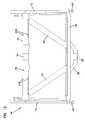
- each of the elongated rail members 72 of the frame assembly 62slide within corresponding rail grooves 170 formed in the mounting guides 30 .
- each of the elongated rail members 72further includes a stop 172 .
- the stopsrides within another groove 174 ( FIG. 17 ) formed in the mounting guides 30 .
- the groove 174 that receives the stop 172has closed ends that limit the travel of the frame assembly 62 relative to the fixed mounting guides 30 .
- the stop 172 and closed-end groove 174prevent the frame assembly 62 from separating from the mounting guide 30 in both a forward direction and a rearward direction.
- the living hinge 70With the living hinge 70 again activated (i.e., the locking tabs disengaged from the forward slot 178 of the mounting guides 30 ) and the shoulder 108 of the lever arm 68 engaged against the edge 195 of the first frame piece 64 , the rail members 72 of the sliding adapter pack slide rearward within the grooves 170 of the mounting guides 30 .
- the locking tabs 140 , 148 of the living hinge 70also slide within the cut-out region 198 ( FIGS. 17 and 19 ) of each mounting guide 30 and eventually contact another ramped surface 197 of the guide 30 .
- the ramped surface 197aids in guiding each locking tabs 140 , 148 into the rearward slot 176 of the mounting guide 30 .
Landscapes
- Engineering & Computer Science (AREA)
- Computer Networks & Wireless Communication (AREA)
- Light Guides In General And Applications Therefor (AREA)
- Connector Housings Or Holding Contact Members (AREA)
Abstract
Description
Claims (19)
Priority Applications (1)
| Application Number | Priority Date | Filing Date | Title |
|---|---|---|---|
| US12/287,271US8179684B2 (en) | 2007-10-29 | 2008-10-07 | Sliding adapter panel with living hinge and forward/rearward locking |
Applications Claiming Priority (2)
| Application Number | Priority Date | Filing Date | Title |
|---|---|---|---|
| US98342507P | 2007-10-29 | 2007-10-29 | |
| US12/287,271US8179684B2 (en) | 2007-10-29 | 2008-10-07 | Sliding adapter panel with living hinge and forward/rearward locking |
Publications (2)
| Publication Number | Publication Date |
|---|---|
| US20090129033A1 US20090129033A1 (en) | 2009-05-21 |
| US8179684B2true US8179684B2 (en) | 2012-05-15 |
Family
ID=40456707
Family Applications (1)
| Application Number | Title | Priority Date | Filing Date |
|---|---|---|---|
| US12/287,271Expired - Fee RelatedUS8179684B2 (en) | 2007-10-29 | 2008-10-07 | Sliding adapter panel with living hinge and forward/rearward locking |
Country Status (2)
| Country | Link |
|---|---|
| US (1) | US8179684B2 (en) |
| WO (1) | WO2009058758A1 (en) |
Cited By (38)
| Publication number | Priority date | Publication date | Assignee | Title |
|---|---|---|---|---|
| US20110228473A1 (en)* | 2010-02-12 | 2011-09-22 | Chad Anderson | Communications bladed panel systems |
| US20120230763A1 (en)* | 2011-03-09 | 2012-09-13 | King Slide Works Co., Ltd. | Locking device for case of portable electronic device |
| US20120248049A1 (en)* | 2011-03-30 | 2012-10-04 | Graham Phillip Moore | Rackmount Laptop Support |
| US20140355217A1 (en)* | 2013-05-29 | 2014-12-04 | Go!Foton Holdings, Inc. | Patch panel assembly |
| US20150131958A1 (en)* | 2007-01-19 | 2015-05-14 | Adc Telecommunications, Inc. | Adapter panel with lateral sliding adapter arrays |
| US20150316738A1 (en)* | 2014-05-05 | 2015-11-05 | Corning Optical Communications LLC | Fiber optic cable holder for a cassette |
| US9329353B2 (en)* | 2011-10-07 | 2016-05-03 | Commscope Technologies Llc | Slidable fiber optic connection module with cable slack management |
| US9435974B2 (en) | 2007-01-19 | 2016-09-06 | Commscope Technologies Llc | Adapter panel with lateral sliding adapter arrays |
| US9494758B2 (en) | 2014-04-03 | 2016-11-15 | Commscope Technologies Llc | Fiber optic distribution system |
| US9523833B2 (en) | 2013-02-05 | 2016-12-20 | Commscope Technologies Llc | Slidable telecommunications tray with cable slack management |
| US9541726B2 (en) | 2013-04-24 | 2017-01-10 | Adc Czech Republic, S.R.O. | Optical fiber distribution system |
| US9568699B2 (en) | 2013-01-29 | 2017-02-14 | CommScope Connectivity Belgium BVBA | Optical fiber distribution system |
| US9581781B2 (en) | 2013-06-24 | 2017-02-28 | Go!Foton Holdings, Inc. | Patch panel pivoting tray cable retention mechanisms |
| US9584879B2 (en) | 2013-05-29 | 2017-02-28 | Go!Foton Holdings, Inc. | Patch panel cable retention mechanisms |
| US9690065B2 (en) | 2014-09-12 | 2017-06-27 | Panduit Corp. | High density fiber enclosure and method |
| US9728945B2 (en) | 2013-03-13 | 2017-08-08 | Go!Foton Holdings, Inc. | Patch panel assembly |
| US10215944B2 (en) | 2016-06-30 | 2019-02-26 | Panduit Corp. | Modular fiber optic tray |
| US10261281B2 (en) | 2015-04-03 | 2019-04-16 | CommScope Connectivity Belgium BVBA | Telecommunications distribution elements |
| US10291969B2 (en) | 2017-02-14 | 2019-05-14 | Go!Foton Holdings, Inc. | Rear cable management |
| US10359593B2 (en) | 2014-06-23 | 2019-07-23 | Commscope Technologies Llc | Bladed chassis systems |
| US10409020B2 (en) | 2013-04-24 | 2019-09-10 | CommScope Connectivity Belgium BVBA | Universal mounting mechanism for mounting a telecommunications chassis to a telecommunciations fixture |
| US10416406B1 (en) | 2018-03-01 | 2019-09-17 | Afl Telecommunications Llc | Communications module housing |
| US10451828B1 (en) | 2018-11-09 | 2019-10-22 | Afl Telecommunications Llc | Communications module housing |
| US20220124931A1 (en)* | 2020-10-20 | 2022-04-21 | Wistron Corporation | Module ejection mechanism and expansion assembly having the same |
| US11409067B2 (en) | 2018-08-31 | 2022-08-09 | CommScope Connectivity Belgium BVBA | Frame assemblies for optical fiber distribution elements |
| US11448831B2 (en) | 2018-08-31 | 2022-09-20 | CommScope Connectivity Belgium BVBA | Frame assemblies for optical fiber distribution elements |
| US11448845B2 (en) | 2018-08-31 | 2022-09-20 | CommScope Connectivity Belgium BVBA | Frame assemblies for optical fiber distribution elements |
| US11448844B2 (en) | 2018-08-31 | 2022-09-20 | CommScope Connectivity Belgium BVBA | Frame assemblies for optical fiber distribution elements |
| US11567281B2 (en) | 2013-09-23 | 2023-01-31 | Commscope Connectivity Uk Limited | Telecommunications chassis |
| US11635578B2 (en) | 2018-04-17 | 2023-04-25 | CommScope Connectivity Belgium BVBA | Telecommunications distribution elements |
| US11852882B2 (en) | 2018-02-28 | 2023-12-26 | Commscope Technologies Llc | Packaging assembly for telecommunications equipment |
| US11947177B2 (en) | 2019-01-25 | 2024-04-02 | CommScope Connectivity Belgium BVBA | Frame assemblies for optical fiber distribution elements |
| US11994732B2 (en) | 2019-04-01 | 2024-05-28 | Afl Telecommunications Llc | Fiber optic tray systems |
| US12007615B2 (en) | 2018-10-23 | 2024-06-11 | CommScope Connectivity Belgium BVBA | Frame assemblies for optical fiber distribution elements |
| US12050358B2 (en) | 2018-08-31 | 2024-07-30 | CommScope Connectivity Belgium BVBA | Frame assemblies for optical fiber distribution elements |
| US12055762B2 (en) | 2020-07-02 | 2024-08-06 | Go!Foton Holdings, Inc. | Intelligent optical switch |
| US12099246B2 (en) | 2020-01-24 | 2024-09-24 | CommScope Connectivity Belgium BVBA | Telecommunications distribution elements |
| US12174443B2 (en) | 2020-01-22 | 2024-12-24 | CommScope Connectivity Belgium BVBA | Cable termination units for optical fiber distribution elements |
Families Citing this family (14)
| Publication number | Priority date | Publication date | Assignee | Title |
|---|---|---|---|---|
| US8452148B2 (en)* | 2008-08-29 | 2013-05-28 | Corning Cable Systems Llc | Independently translatable modules and fiber optic equipment trays in fiber optic equipment |
| US11294136B2 (en) | 2008-08-29 | 2022-04-05 | Corning Optical Communications LLC | High density and bandwidth fiber optic apparatuses and related equipment and methods |
| EP2443497B1 (en) | 2009-06-19 | 2020-03-04 | Corning Cable Systems LLC | High density and bandwidth fiber optic apparatus |
| WO2012068013A2 (en)* | 2010-11-15 | 2012-05-24 | Adc Telecommunications, Inc. | Cable management in rack systems |
| US10082636B2 (en) | 2012-09-21 | 2018-09-25 | Commscope Technologies Llc | Slidable fiber optic connection module with cable slack management |
| US9423579B2 (en)* | 2013-03-05 | 2016-08-23 | Finisar Corporation | Latch mechanism for communication module |
| ES2851948T3 (en) | 2016-04-19 | 2021-09-09 | Commscope Inc North Carolina | Telecom rack with slide out trays |
| WO2017184501A1 (en) | 2016-04-19 | 2017-10-26 | Commscope, Inc. Of North Carolina | Door assembly for a telecommunications chassis with a combination hinge structure |
| CN205787267U (en)* | 2016-05-25 | 2016-12-07 | 连展科技电子(昆山)有限公司 | Optical fiber cassette track structure |
| TWM545913U (en)* | 2017-03-07 | 2017-07-21 | 連展科技股份有限公司 | Fiber cartridge swapping device |
| US11385429B2 (en) | 2017-10-18 | 2022-07-12 | Commscope Technologies Llc | Fiber optic connection cassette |
| CN109843011B (en)* | 2017-11-28 | 2020-07-14 | 台达电子工业股份有限公司 | Latch module and detachable assembling structure suitable for same |
| WO2019204317A1 (en) | 2018-04-16 | 2019-10-24 | Commscope Technologies Llc | Adapter structure |
| US11048055B2 (en) | 2018-11-16 | 2021-06-29 | Panduit Corp. | Fiber optic cassette |
Citations (29)
| Publication number | Priority date | Publication date | Assignee | Title |
|---|---|---|---|---|
| US4765710A (en) | 1985-07-30 | 1988-08-23 | Siemens Aktiengesellschaft | Distributing frame for optical waveguides and the like |
| EP0341027A2 (en) | 1988-05-02 | 1989-11-08 | Gte Control Devices Of Puerto Rico Incorporated | Fiber distribution panel |
| US5129030A (en) | 1991-05-30 | 1992-07-07 | At&T Bell Laboratories | Movable lightguide connector panel |
| US5167001A (en) | 1991-09-03 | 1992-11-24 | Northern Telecom Limited | Optical fiber storage and connector tray and shelf and tray assembly |
| US5497444A (en) | 1994-01-21 | 1996-03-05 | Adc Telecommunications, Inc. | High-density fiber distribution frame |
| US5758003A (en) | 1996-03-15 | 1998-05-26 | Adc Telecommunications, Inc. | High density fiber management |
| US5826922A (en)* | 1997-03-13 | 1998-10-27 | Silicon Graphics, Inc. | Rotary latch assembly for a computer housing |
| US5945633A (en) | 1996-05-23 | 1999-08-31 | The Siemon Company | Rack mountable cable distribution enclosure having an angled adapter plate bracket |
| US6252514B1 (en)* | 1999-06-07 | 2001-06-26 | Convergent Technologies, Inc. | Hot-swap assembly for computers |
| US6424781B1 (en) | 1999-03-01 | 2002-07-23 | Adc Telecommunications, Inc. | Optical fiber distribution frame with pivoting connector panels |
| US6504988B1 (en) | 2000-01-24 | 2003-01-07 | Adc Telecommunications, Inc. | Cable management panel with sliding drawer |
| US6591051B2 (en) | 2001-11-16 | 2003-07-08 | Adc Telecommunications, Inc. | Fiber termination block with angled slide |
| US20030174996A1 (en) | 2002-03-15 | 2003-09-18 | Fiber Optic Network Solutions, Inc. | Optical fiber enclosure system using integrated optical connector and coupler assembly |
| US20030223723A1 (en) | 2002-05-28 | 2003-12-04 | Massey Gaines N. | Reconfigurable fiber optic cable management enclosure |
| US20040062002A1 (en)* | 2002-09-27 | 2004-04-01 | International Business Machines Corporation | High density modular input/output package in a data processing system |
| US6715619B2 (en) | 2002-07-22 | 2004-04-06 | Adc Telecommunications, Inc. | Fiber management drawer and patch panel |
| US20040086252A1 (en) | 2002-11-05 | 2004-05-06 | Smith Trevor D. | Fiber panel with integrated couplers |
| US6760531B1 (en) | 1999-03-01 | 2004-07-06 | Adc Telecommunications, Inc. | Optical fiber distribution frame with outside plant enclosure |
| WO2005051006A1 (en) | 2003-11-13 | 2005-06-02 | Adc Telecommunications, Inc. | Module with interchangeable card |
| US6908342B2 (en)* | 2001-10-02 | 2005-06-21 | Canon Kabushiki Kaisha | Connector, electronic equipment using the connector and information processing unit |
| US6920274B2 (en) | 2003-12-23 | 2005-07-19 | Adc Telecommunications, Inc. | High density optical fiber distribution frame with modules |
| US6937807B2 (en) | 2002-04-24 | 2005-08-30 | Adc Telecommunications, Inc. | Cable management panel with sliding drawer |
| US6944383B1 (en) | 2004-04-12 | 2005-09-13 | Adc Telecommunications, Inc. | Cable management panel with sliding drawer and methods |
| EP1603345A2 (en) | 2004-06-01 | 2005-12-07 | Commscope Solutions Properties, LLC | Modular communications shelf system and methods for using the same |
| US7194181B2 (en) | 2005-03-31 | 2007-03-20 | Adc Telecommunications, Inc. | Adapter block including connector storage |
| US7200316B2 (en) | 2003-11-26 | 2007-04-03 | Corning Cable Systems Llc | Connector housing for a communication network |
| US20080175551A1 (en)* | 2007-01-19 | 2008-07-24 | Mark Smrha | Adapter panel with lateral sliding adapter arrays |
| US20080175552A1 (en) | 2007-01-19 | 2008-07-24 | Mark Smrha | Adapter panel with lateral sliding adapter arrays |
| US7474828B2 (en) | 2006-10-02 | 2009-01-06 | Emerson Network Power, Energy Systems, North America, Inc. | Slack limiting fiber management system for an optic fiber distribution hub |
- 2008
- 2008-10-07USUS12/287,271patent/US8179684B2/ennot_activeExpired - Fee Related
- 2008-10-28WOPCT/US2008/081424patent/WO2009058758A1/enactiveApplication Filing
Patent Citations (31)
| Publication number | Priority date | Publication date | Assignee | Title |
|---|---|---|---|---|
| US4765710A (en) | 1985-07-30 | 1988-08-23 | Siemens Aktiengesellschaft | Distributing frame for optical waveguides and the like |
| EP0341027A2 (en) | 1988-05-02 | 1989-11-08 | Gte Control Devices Of Puerto Rico Incorporated | Fiber distribution panel |
| US5129030A (en) | 1991-05-30 | 1992-07-07 | At&T Bell Laboratories | Movable lightguide connector panel |
| US5167001A (en) | 1991-09-03 | 1992-11-24 | Northern Telecom Limited | Optical fiber storage and connector tray and shelf and tray assembly |
| US5497444A (en) | 1994-01-21 | 1996-03-05 | Adc Telecommunications, Inc. | High-density fiber distribution frame |
| US5717810A (en) | 1994-01-21 | 1998-02-10 | Adc Telecommunications, Inc. | High-density fiber distribution frame |
| US5758003A (en) | 1996-03-15 | 1998-05-26 | Adc Telecommunications, Inc. | High density fiber management |
| US5945633A (en) | 1996-05-23 | 1999-08-31 | The Siemon Company | Rack mountable cable distribution enclosure having an angled adapter plate bracket |
| US5826922A (en)* | 1997-03-13 | 1998-10-27 | Silicon Graphics, Inc. | Rotary latch assembly for a computer housing |
| US6424781B1 (en) | 1999-03-01 | 2002-07-23 | Adc Telecommunications, Inc. | Optical fiber distribution frame with pivoting connector panels |
| US6760531B1 (en) | 1999-03-01 | 2004-07-06 | Adc Telecommunications, Inc. | Optical fiber distribution frame with outside plant enclosure |
| US6252514B1 (en)* | 1999-06-07 | 2001-06-26 | Convergent Technologies, Inc. | Hot-swap assembly for computers |
| US6504988B1 (en) | 2000-01-24 | 2003-01-07 | Adc Telecommunications, Inc. | Cable management panel with sliding drawer |
| US6908342B2 (en)* | 2001-10-02 | 2005-06-21 | Canon Kabushiki Kaisha | Connector, electronic equipment using the connector and information processing unit |
| US6591051B2 (en) | 2001-11-16 | 2003-07-08 | Adc Telecommunications, Inc. | Fiber termination block with angled slide |
| US20030174996A1 (en) | 2002-03-15 | 2003-09-18 | Fiber Optic Network Solutions, Inc. | Optical fiber enclosure system using integrated optical connector and coupler assembly |
| US6937807B2 (en) | 2002-04-24 | 2005-08-30 | Adc Telecommunications, Inc. | Cable management panel with sliding drawer |
| US20030223723A1 (en) | 2002-05-28 | 2003-12-04 | Massey Gaines N. | Reconfigurable fiber optic cable management enclosure |
| US6715619B2 (en) | 2002-07-22 | 2004-04-06 | Adc Telecommunications, Inc. | Fiber management drawer and patch panel |
| US20040062002A1 (en)* | 2002-09-27 | 2004-04-01 | International Business Machines Corporation | High density modular input/output package in a data processing system |
| US20040086252A1 (en) | 2002-11-05 | 2004-05-06 | Smith Trevor D. | Fiber panel with integrated couplers |
| US6804447B2 (en) | 2002-11-05 | 2004-10-12 | Adc Telecommunications, Inc. | Fiber panel with integrated couplers |
| WO2005051006A1 (en) | 2003-11-13 | 2005-06-02 | Adc Telecommunications, Inc. | Module with interchangeable card |
| US7200316B2 (en) | 2003-11-26 | 2007-04-03 | Corning Cable Systems Llc | Connector housing for a communication network |
| US6920274B2 (en) | 2003-12-23 | 2005-07-19 | Adc Telecommunications, Inc. | High density optical fiber distribution frame with modules |
| US6944383B1 (en) | 2004-04-12 | 2005-09-13 | Adc Telecommunications, Inc. | Cable management panel with sliding drawer and methods |
| EP1603345A2 (en) | 2004-06-01 | 2005-12-07 | Commscope Solutions Properties, LLC | Modular communications shelf system and methods for using the same |
| US7194181B2 (en) | 2005-03-31 | 2007-03-20 | Adc Telecommunications, Inc. | Adapter block including connector storage |
| US7474828B2 (en) | 2006-10-02 | 2009-01-06 | Emerson Network Power, Energy Systems, North America, Inc. | Slack limiting fiber management system for an optic fiber distribution hub |
| US20080175551A1 (en)* | 2007-01-19 | 2008-07-24 | Mark Smrha | Adapter panel with lateral sliding adapter arrays |
| US20080175552A1 (en) | 2007-01-19 | 2008-07-24 | Mark Smrha | Adapter panel with lateral sliding adapter arrays |
Non-Patent Citations (5)
| Title |
|---|
| ADC Telecommunications Fiber Outside Plant Systems, 4 pgs.; Aug. 1998. |
| ADC Telecommunications Fiber Panel Products, Second Edition, 6 pgs.; Jul. 1996. |
| Corning Cable Systems; Jumper Routing Procedure for Enhanced Management Frame; dated Apr. 2002; 4 pgs. |
| Drawing of ADC Telecommunications Drawer, 1 page; Aug. 2006. |
| Drawing of ADC Telecommunications Drawer, 2 pages, Nov. 2006. |
Cited By (133)
| Publication number | Priority date | Publication date | Assignee | Title |
|---|---|---|---|---|
| US9638879B2 (en) | 2007-01-19 | 2017-05-02 | Commscope Technologies Llc | Adapter panel with lateral sliding adapter arrays |
| US10739544B2 (en) | 2007-01-19 | 2020-08-11 | Commscope Technologies Llc | Adapter panel with lateral sliding adapter arrays |
| US10969553B2 (en) | 2007-01-19 | 2021-04-06 | Commscope Technologies Llc | Adapter panel with lateral sliding adapter arrays |
| US10473874B2 (en) | 2007-01-19 | 2019-11-12 | Commscope Technologies Llc | Adapter panel with lateral sliding adapter arrays |
| US11262517B2 (en) | 2007-01-19 | 2022-03-01 | Commscope Technologies Llc | Adapter panel with lateral sliding adapter arrays |
| US11269150B2 (en) | 2007-01-19 | 2022-03-08 | Commscope Technologies Llc | Adapter panel with lateral sliding adapter arrays |
| US10310204B2 (en) | 2007-01-19 | 2019-06-04 | Commscope Technologies Llc | Adapter panel with lateral sliding adapter arrays |
| US11300747B2 (en) | 2007-01-19 | 2022-04-12 | Commscope Technologies Llc | Adapter panel with lateral sliding adapter arrays |
| US11314028B2 (en) | 2007-01-19 | 2022-04-26 | Commscope Technologies Llc | Adapter panel with lateral sliding adapter arrays |
| US20150131958A1 (en)* | 2007-01-19 | 2015-05-14 | Adc Telecommunications, Inc. | Adapter panel with lateral sliding adapter arrays |
| US9097871B2 (en)* | 2007-01-19 | 2015-08-04 | Adc Telecommunications, Inc. | Adapter panel with lateral sliding adapter arrays |
| US12164168B2 (en) | 2007-01-19 | 2024-12-10 | Commscope Technologies Llc | Adapter panel with lateral sliding adapter arrays |
| US11333840B2 (en) | 2007-01-19 | 2022-05-17 | Commscope Technologies Llc | Adapter panel with lateral sliding adapter arrays |
| US10203464B1 (en) | 2007-01-19 | 2019-02-12 | Commscope Technologies Llc | Adapter panel with lateral sliding adapter arrays |
| US9995897B2 (en) | 2007-01-19 | 2018-06-12 | Commscope Technologies Llc | Adapter panel with lateral sliding adapter arrays |
| US11789225B2 (en) | 2007-01-19 | 2023-10-17 | Commscope Technologies Llc | Adapter panel with lateral sliding adapter arrays |
| US9709764B2 (en) | 2007-01-19 | 2017-07-18 | Commscope Technologies Llc | Adapter panel with lateral sliding adapter arrays |
| US9703059B2 (en) | 2007-01-19 | 2017-07-11 | Commscope Technologies Llc | Adapter panel with lateral sliding adapter arrays |
| US9690066B2 (en) | 2007-01-19 | 2017-06-27 | Commscope Technologies Llc | Adapter panel with lateral sliding adapter arrays |
| US9435974B2 (en) | 2007-01-19 | 2016-09-06 | Commscope Technologies Llc | Adapter panel with lateral sliding adapter arrays |
| US9435976B2 (en) | 2007-01-19 | 2016-09-06 | Commscope Technologies Llc | Adapter panel with lateral sliding adapter arrays |
| US9448378B2 (en) | 2007-01-19 | 2016-09-20 | Commscope Technologies Llc | Adapter panel with lateral sliding adapter arrays |
| US9448379B2 (en) | 2007-01-19 | 2016-09-20 | Commscope Technologies Llc | Adapter panel with lateral sliding adapter arrays |
| US12111507B2 (en) | 2007-01-19 | 2024-10-08 | Commscope Technologies Llc | Adapter panel with lateral sliding adapter arrays |
| US9488796B2 (en) | 2007-01-19 | 2016-11-08 | Commscope Technologies Llc | Adapter panel with lateral sliding adapter arrays |
| US9645342B2 (en) | 2007-01-19 | 2017-05-09 | Commscope Technologies Llc | Adapter panel with lateral sliding adapter arrays |
| US9638880B2 (en) | 2007-01-19 | 2017-05-02 | Commscope Technologies Llc | Adapter panel with lateral sliding adapter arrays |
| US10123444B2 (en) | 2010-02-12 | 2018-11-06 | Commscope Technologies Llc | Communications bladed panel systems |
| US8934253B2 (en) | 2010-02-12 | 2015-01-13 | Adc Telecommunications, Inc. | Communications bladed panel systems |
| US8923013B2 (en) | 2010-02-12 | 2014-12-30 | Adc Telecommunications, Inc. | Communications bladed panel systems |
| US9549484B2 (en) | 2010-02-12 | 2017-01-17 | Commscope Technologies Llc | Communications bladed panel systems |
| US9532481B2 (en) | 2010-02-12 | 2016-12-27 | Commscope Technologies Llc | Communications bladed panel systems |
| US8934252B2 (en) | 2010-02-12 | 2015-01-13 | Adc Telecommunications, Inc. | Communications bladed panel systems |
| US20110228473A1 (en)* | 2010-02-12 | 2011-09-22 | Chad Anderson | Communications bladed panel systems |
| US9532482B2 (en) | 2010-02-12 | 2016-12-27 | Commscope Technologies Llc | Communications bladed panel systems |
| US9020319B2 (en) | 2010-02-12 | 2015-04-28 | Adc Telecommunications, Inc. | Communications bladed panel systems |
| US9198320B2 (en) | 2010-02-12 | 2015-11-24 | Tyco Electronics Services Gmbh | Communications bladed panel systems |
| US9213363B2 (en) | 2010-02-12 | 2015-12-15 | Tyco Electronics Services Gmbh | Communications bladed panel systems |
| US9223105B2 (en) | 2010-02-12 | 2015-12-29 | Commscope Technologies Llc | Communications bladed panel systems |
| US9265172B2 (en) | 2010-02-12 | 2016-02-16 | Commscope Technologies Llc | Communications bladed panel systems |
| US20120230763A1 (en)* | 2011-03-09 | 2012-09-13 | King Slide Works Co., Ltd. | Locking device for case of portable electronic device |
| US8801050B2 (en)* | 2011-03-09 | 2014-08-12 | King Slide Works Co., Ltd. | Locking device for case of portable electronic device |
| US20120248049A1 (en)* | 2011-03-30 | 2012-10-04 | Graham Phillip Moore | Rackmount Laptop Support |
| US9295179B2 (en)* | 2011-03-30 | 2016-03-22 | Graham Phillip Moore | Rackmount laptop support |
| US9329353B2 (en)* | 2011-10-07 | 2016-05-03 | Commscope Technologies Llc | Slidable fiber optic connection module with cable slack management |
| US9715075B2 (en) | 2011-10-07 | 2017-07-25 | Commscope Technologies Llc | Slidable fiber optic connection module with cable slack management |
| US9354416B2 (en) | 2011-10-07 | 2016-05-31 | Commscope Technologies Llc | Slidable fiber optic connection module with cable slack management |
| US11614594B2 (en) | 2013-01-29 | 2023-03-28 | CommScope Connectivity Belgium BVBA | Optical fiber distribution system |
| US12019300B2 (en) | 2013-01-29 | 2024-06-25 | CommScope Connectivity Belgium BVBA | Optical fiber distribution system |
| US12422640B2 (en) | 2013-01-29 | 2025-09-23 | CommScope Connectivity Belgium BVBA | Optical fiber distribution system |
| US10732373B2 (en) | 2013-01-29 | 2020-08-04 | CommScope Connectivity Belgium BVBA | Optical fiber distribution system |
| US10126515B2 (en) | 2013-01-29 | 2018-11-13 | CommScope Connectivity Belgium BVBA | Optical fiber distribution system |
| US9568699B2 (en) | 2013-01-29 | 2017-02-14 | CommScope Connectivity Belgium BVBA | Optical fiber distribution system |
| US11320618B2 (en) | 2013-01-29 | 2022-05-03 | CommScope Connectivity Belgium BVBA | Optical fiber distribution system |
| US11506854B2 (en) | 2013-02-05 | 2022-11-22 | Commscope Technologies Llc | Slidable telecommunications tray with cable slack management |
| US10209471B2 (en) | 2013-02-05 | 2019-02-19 | Commscope Technologies Llc | Slidable telecommunications tray with cable slack management |
| US9523833B2 (en) | 2013-02-05 | 2016-12-20 | Commscope Technologies Llc | Slidable telecommunications tray with cable slack management |
| US10732371B2 (en) | 2013-02-05 | 2020-08-04 | Commscope Technologies Llc | Slidable telecommunications tray with cable slack management |
| US9810869B2 (en) | 2013-02-05 | 2017-11-07 | Commscope Technologies Llc | Slidable telecommunications tray with cable slack management |
| US11073672B2 (en) | 2013-02-05 | 2021-07-27 | Commscope Technologies Llc | Slidable telecommunications tray with cable slack management |
| US9728945B2 (en) | 2013-03-13 | 2017-08-08 | Go!Foton Holdings, Inc. | Patch panel assembly |
| US10409020B2 (en) | 2013-04-24 | 2019-09-10 | CommScope Connectivity Belgium BVBA | Universal mounting mechanism for mounting a telecommunications chassis to a telecommunciations fixture |
| US11092766B2 (en) | 2013-04-24 | 2021-08-17 | CommScope Connectivity Belgium BVBA | Universal mounting mechanism for mounting a telecommunications chassis to a telecommunications fixture |
| US10107984B2 (en) | 2013-04-24 | 2018-10-23 | CommScope Connectivity Belgium BVBA | Optical fiber distribution system |
| US11579395B2 (en) | 2013-04-24 | 2023-02-14 | CommScope Connectivity Belgium BVBA | Optical fiber distribution system |
| US11002936B2 (en) | 2013-04-24 | 2021-05-11 | CommScope Connectivity Belgium BVBA | Optical fiber distribution system |
| US9541726B2 (en) | 2013-04-24 | 2017-01-10 | Adc Czech Republic, S.R.O. | Optical fiber distribution system |
| US10746950B2 (en) | 2013-04-24 | 2020-08-18 | CommScope Connectivity Belgium BVBA | Optical fiber distribution system |
| US11982855B2 (en) | 2013-04-24 | 2024-05-14 | CommScope Connectivity Belgium BVBA | Universal mounting mechanism for mounting a telecommunications chassis to a telecommunications fixture |
| US11988887B2 (en) | 2013-04-24 | 2024-05-21 | CommScope Connectivity Belgium BVBA | Optical fiber distribution system |
| US9584879B2 (en) | 2013-05-29 | 2017-02-28 | Go!Foton Holdings, Inc. | Patch panel cable retention mechanisms |
| US9462356B2 (en)* | 2013-05-29 | 2016-10-04 | Go!Foton Holdings, Inc. | Patch panel assembly |
| US9781493B2 (en) | 2013-05-29 | 2017-10-03 | Go!Foton Holding, Inc. | Patch panel tray assembly |
| US20140355217A1 (en)* | 2013-05-29 | 2014-12-04 | Go!Foton Holdings, Inc. | Patch panel assembly |
| US9581781B2 (en) | 2013-06-24 | 2017-02-28 | Go!Foton Holdings, Inc. | Patch panel pivoting tray cable retention mechanisms |
| US11567281B2 (en) | 2013-09-23 | 2023-01-31 | Commscope Connectivity Uk Limited | Telecommunications chassis |
| US12025846B2 (en) | 2013-09-23 | 2024-07-02 | Commscope Connectivity Uk Limited | Telecommunications chassis |
| US9977212B2 (en) | 2014-04-03 | 2018-05-22 | Commscope Technologies Llc | Fiber optic distribution system |
| US9494758B2 (en) | 2014-04-03 | 2016-11-15 | Commscope Technologies Llc | Fiber optic distribution system |
| US10481357B2 (en) | 2014-04-03 | 2019-11-19 | Commscope Technologies Llc | Fiber optic distribution system |
| US20150316738A1 (en)* | 2014-05-05 | 2015-11-05 | Corning Optical Communications LLC | Fiber optic cable holder for a cassette |
| US12164169B2 (en) | 2014-06-23 | 2024-12-10 | Commscope Technologies Llc | Bladed chassis systems |
| US11815727B2 (en) | 2014-06-23 | 2023-11-14 | Commscope Technologies Llc | Bladed chassis systems |
| US10359593B2 (en) | 2014-06-23 | 2019-07-23 | Commscope Technologies Llc | Bladed chassis systems |
| US10852500B2 (en) | 2014-06-23 | 2020-12-01 | Commscope Technologies Llc | Bladed chassis systems |
| US11294134B2 (en) | 2014-06-23 | 2022-04-05 | Commscope Technologies Llc | Bladed chassis systems |
| US10606013B2 (en) | 2014-09-12 | 2020-03-31 | Panduit Corp. | High density fiber enclosure and method |
| US10317637B2 (en) | 2014-09-12 | 2019-06-11 | Panduit Corp. | High density fiber enclosure and method |
| US10268013B2 (en)* | 2014-09-12 | 2019-04-23 | Panduit Corp. | High density fiber enclosure and method |
| US12228782B2 (en) | 2014-09-12 | 2025-02-18 | Panduit Corp. | High density fiber enclosure and method |
| US9690065B2 (en) | 2014-09-12 | 2017-06-27 | Panduit Corp. | High density fiber enclosure and method |
| US11105995B2 (en) | 2014-09-12 | 2021-08-31 | Panduit Corp. | High density fiber enclosure and method |
| US10768385B2 (en) | 2014-09-12 | 2020-09-08 | Panduit Corp. | High density fiber enclosure and method |
| US11624888B2 (en)* | 2014-09-12 | 2023-04-11 | Panduit Corp. | High density fiber enclosure and method |
| US20170285289A1 (en)* | 2014-09-12 | 2017-10-05 | Panduit Corp. | High Density Fiber Enclosure and Method |
| US9864158B2 (en) | 2014-09-12 | 2018-01-09 | Panduit Corp. | High density fiber enclosure and method |
| US10698171B2 (en) | 2014-09-12 | 2020-06-30 | Panduit Corp. | High density fiber enclosure and method |
| US12055779B2 (en) | 2015-04-03 | 2024-08-06 | CommScope Connectivity Belgium BVBA | Telecommunications distribution elements |
| US10908375B2 (en) | 2015-04-03 | 2021-02-02 | CommScope Connectivity Belgium BVBA | Telecommunications distribution elements |
| US11592639B2 (en) | 2015-04-03 | 2023-02-28 | CommScope Connectivity Belgium BVBA | Telecommunications distribution elements |
| US10261281B2 (en) | 2015-04-03 | 2019-04-16 | CommScope Connectivity Belgium BVBA | Telecommunications distribution elements |
| US12105338B2 (en) | 2016-06-30 | 2024-10-01 | Panduit Corp. | Modular fiber optic tray |
| US11709331B2 (en) | 2016-06-30 | 2023-07-25 | Panduit Corp. | Modular fiber optic tray |
| US11372185B2 (en) | 2016-06-30 | 2022-06-28 | Panduit Corp. | Modular fiber optic tray |
| US10725258B2 (en) | 2016-06-30 | 2020-07-28 | Panduit Corp. | Modular fiber optic tray |
| US10215944B2 (en) | 2016-06-30 | 2019-02-26 | Panduit Corp. | Modular fiber optic tray |
| US10291969B2 (en) | 2017-02-14 | 2019-05-14 | Go!Foton Holdings, Inc. | Rear cable management |
| US11852882B2 (en) | 2018-02-28 | 2023-12-26 | Commscope Technologies Llc | Packaging assembly for telecommunications equipment |
| US10823927B2 (en) | 2018-03-01 | 2020-11-03 | Afl Telecommunications Llc | Communications module housing |
| US10416406B1 (en) | 2018-03-01 | 2019-09-17 | Afl Telecommunications Llc | Communications module housing |
| US11635578B2 (en) | 2018-04-17 | 2023-04-25 | CommScope Connectivity Belgium BVBA | Telecommunications distribution elements |
| US11409067B2 (en) | 2018-08-31 | 2022-08-09 | CommScope Connectivity Belgium BVBA | Frame assemblies for optical fiber distribution elements |
| US12197025B2 (en) | 2018-08-31 | 2025-01-14 | CommScope Connectivity Belgium BVBA | Frame assemblies for optical fiber distribution elements |
| US12197026B2 (en) | 2018-08-31 | 2025-01-14 | CommScope Connectivity Belgium BVBA | Frame assemblies for optical fiber distribution elements |
| US12197027B2 (en) | 2018-08-31 | 2025-01-14 | CommScope Connectivity Belgium BVBA | Frame assemblies for optical fiber distribution elements |
| US12050358B2 (en) | 2018-08-31 | 2024-07-30 | CommScope Connectivity Belgium BVBA | Frame assemblies for optical fiber distribution elements |
| US12306451B2 (en) | 2018-08-31 | 2025-05-20 | CommScope Connectivity Belgium BVBA | Frame assemblies for optical fiber distribution elements |
| US12189188B2 (en) | 2018-08-31 | 2025-01-07 | CommScope Connectivity Belgium BVBA | Frame assemblies for optical fiber distribution elements |
| US11448844B2 (en) | 2018-08-31 | 2022-09-20 | CommScope Connectivity Belgium BVBA | Frame assemblies for optical fiber distribution elements |
| US11448831B2 (en) | 2018-08-31 | 2022-09-20 | CommScope Connectivity Belgium BVBA | Frame assemblies for optical fiber distribution elements |
| US11448845B2 (en) | 2018-08-31 | 2022-09-20 | CommScope Connectivity Belgium BVBA | Frame assemblies for optical fiber distribution elements |
| US12007615B2 (en) | 2018-10-23 | 2024-06-11 | CommScope Connectivity Belgium BVBA | Frame assemblies for optical fiber distribution elements |
| US10451828B1 (en) | 2018-11-09 | 2019-10-22 | Afl Telecommunications Llc | Communications module housing |
| US10802235B2 (en) | 2018-11-09 | 2020-10-13 | Afl Telecommunications Llc | Communications module housing |
| US11947177B2 (en) | 2019-01-25 | 2024-04-02 | CommScope Connectivity Belgium BVBA | Frame assemblies for optical fiber distribution elements |
| US12019297B2 (en) | 2019-04-01 | 2024-06-25 | Afl Telecommunications Llc | Fiber optic tray systems |
| US11994732B2 (en) | 2019-04-01 | 2024-05-28 | Afl Telecommunications Llc | Fiber optic tray systems |
| US12345938B2 (en) | 2019-04-01 | 2025-07-01 | Afl Telecommunications Llc | Fiber optic tray systems |
| US12174443B2 (en) | 2020-01-22 | 2024-12-24 | CommScope Connectivity Belgium BVBA | Cable termination units for optical fiber distribution elements |
| US12099246B2 (en) | 2020-01-24 | 2024-09-24 | CommScope Connectivity Belgium BVBA | Telecommunications distribution elements |
| US12055762B2 (en) | 2020-07-02 | 2024-08-06 | Go!Foton Holdings, Inc. | Intelligent optical switch |
| US20220124931A1 (en)* | 2020-10-20 | 2022-04-21 | Wistron Corporation | Module ejection mechanism and expansion assembly having the same |
| US11963325B2 (en)* | 2020-10-20 | 2024-04-16 | Wistron Corporation | Module ejection mechanism and expansion assembly having the same |
Also Published As
| Publication number | Publication date |
|---|---|
| WO2009058758A1 (en) | 2009-05-07 |
| US20090129033A1 (en) | 2009-05-21 |
Similar Documents
| Publication | Publication Date | Title |
|---|---|---|
| US8179684B2 (en) | Sliding adapter panel with living hinge and forward/rearward locking | |
| US11262517B2 (en) | Adapter panel with lateral sliding adapter arrays | |
| US11789225B2 (en) | Adapter panel with lateral sliding adapter arrays | |
| EP2995981B1 (en) | Independently translatable modules and fiber optic equipment trays in fiber optic equipment |
Legal Events
| Date | Code | Title | Description |
|---|---|---|---|
| AS | Assignment | Owner name:ADC TELECOMMUNICATIONS, INC., MINNESOTA Free format text:ASSIGNMENT OF ASSIGNORS INTEREST;ASSIGNORS:SMRHA, MARK;TINUCCI, THOMAS C;SJODIN, CHAD JAMES;REEL/FRAME:022104/0071 Effective date:20081215 | |
| ZAAA | Notice of allowance and fees due | Free format text:ORIGINAL CODE: NOA | |
| ZAAB | Notice of allowance mailed | Free format text:ORIGINAL CODE: MN/=. | |
| STCF | Information on status: patent grant | Free format text:PATENTED CASE | |
| AS | Assignment | Owner name:TYCO ELECTRONICS SERVICES GMBH, SWITZERLAND Free format text:ASSIGNMENT OF ASSIGNORS INTEREST;ASSIGNOR:ADC TELECOMMUNICATIONS, INC.;REEL/FRAME:036060/0174 Effective date:20110930 | |
| AS | Assignment | Owner name:COMMSCOPE EMEA LIMITED, IRELAND Free format text:ASSIGNMENT OF ASSIGNORS INTEREST;ASSIGNOR:TYCO ELECTRONICS SERVICES GMBH;REEL/FRAME:036956/0001 Effective date:20150828 | |
| AS | Assignment | Owner name:COMMSCOPE TECHNOLOGIES LLC, NORTH CAROLINA Free format text:ASSIGNMENT OF ASSIGNORS INTEREST;ASSIGNOR:COMMSCOPE EMEA LIMITED;REEL/FRAME:037012/0001 Effective date:20150828 | |
| FPAY | Fee payment | Year of fee payment:4 | |
| AS | Assignment | Owner name:JPMORGAN CHASE BANK, N.A., AS COLLATERAL AGENT, ILLINOIS Free format text:PATENT SECURITY AGREEMENT (TERM);ASSIGNOR:COMMSCOPE TECHNOLOGIES LLC;REEL/FRAME:037513/0709 Effective date:20151220 Owner name:JPMORGAN CHASE BANK, N.A., AS COLLATERAL AGENT, ILLINOIS Free format text:PATENT SECURITY AGREEMENT (ABL);ASSIGNOR:COMMSCOPE TECHNOLOGIES LLC;REEL/FRAME:037514/0196 Effective date:20151220 Owner name:JPMORGAN CHASE BANK, N.A., AS COLLATERAL AGENT, IL Free format text:PATENT SECURITY AGREEMENT (ABL);ASSIGNOR:COMMSCOPE TECHNOLOGIES LLC;REEL/FRAME:037514/0196 Effective date:20151220 Owner name:JPMORGAN CHASE BANK, N.A., AS COLLATERAL AGENT, IL Free format text:PATENT SECURITY AGREEMENT (TERM);ASSIGNOR:COMMSCOPE TECHNOLOGIES LLC;REEL/FRAME:037513/0709 Effective date:20151220 | |
| AS | Assignment | Owner name:REDWOOD SYSTEMS, INC., NORTH CAROLINA Free format text:RELEASE BY SECURED PARTY;ASSIGNOR:JPMORGAN CHASE BANK, N.A.;REEL/FRAME:048840/0001 Effective date:20190404 Owner name:COMMSCOPE TECHNOLOGIES LLC, NORTH CAROLINA Free format text:RELEASE BY SECURED PARTY;ASSIGNOR:JPMORGAN CHASE BANK, N.A.;REEL/FRAME:048840/0001 Effective date:20190404 Owner name:ALLEN TELECOM LLC, ILLINOIS Free format text:RELEASE BY SECURED PARTY;ASSIGNOR:JPMORGAN CHASE BANK, N.A.;REEL/FRAME:048840/0001 Effective date:20190404 Owner name:COMMSCOPE, INC. OF NORTH CAROLINA, NORTH CAROLINA Free format text:RELEASE BY SECURED PARTY;ASSIGNOR:JPMORGAN CHASE BANK, N.A.;REEL/FRAME:048840/0001 Effective date:20190404 Owner name:ANDREW LLC, NORTH CAROLINA Free format text:RELEASE BY SECURED PARTY;ASSIGNOR:JPMORGAN CHASE BANK, N.A.;REEL/FRAME:048840/0001 Effective date:20190404 Owner name:COMMSCOPE TECHNOLOGIES LLC, NORTH CAROLINA Free format text:RELEASE BY SECURED PARTY;ASSIGNOR:JPMORGAN CHASE BANK, N.A.;REEL/FRAME:049260/0001 Effective date:20190404 Owner name:ANDREW LLC, NORTH CAROLINA Free format text:RELEASE BY SECURED PARTY;ASSIGNOR:JPMORGAN CHASE BANK, N.A.;REEL/FRAME:049260/0001 Effective date:20190404 Owner name:COMMSCOPE, INC. OF NORTH CAROLINA, NORTH CAROLINA Free format text:RELEASE BY SECURED PARTY;ASSIGNOR:JPMORGAN CHASE BANK, N.A.;REEL/FRAME:049260/0001 Effective date:20190404 Owner name:ALLEN TELECOM LLC, ILLINOIS Free format text:RELEASE BY SECURED PARTY;ASSIGNOR:JPMORGAN CHASE BANK, N.A.;REEL/FRAME:049260/0001 Effective date:20190404 Owner name:REDWOOD SYSTEMS, INC., NORTH CAROLINA Free format text:RELEASE BY SECURED PARTY;ASSIGNOR:JPMORGAN CHASE BANK, N.A.;REEL/FRAME:049260/0001 Effective date:20190404 | |
| AS | Assignment | Owner name:WILMINGTON TRUST, NATIONAL ASSOCIATION, AS COLLATE Free format text:PATENT SECURITY AGREEMENT;ASSIGNOR:COMMSCOPE TECHNOLOGIES LLC;REEL/FRAME:049892/0051 Effective date:20190404 Owner name:JPMORGAN CHASE BANK, N.A., NEW YORK Free format text:ABL SECURITY AGREEMENT;ASSIGNORS:COMMSCOPE, INC. OF NORTH CAROLINA;COMMSCOPE TECHNOLOGIES LLC;ARRIS ENTERPRISES LLC;AND OTHERS;REEL/FRAME:049892/0396 Effective date:20190404 Owner name:JPMORGAN CHASE BANK, N.A., NEW YORK Free format text:TERM LOAN SECURITY AGREEMENT;ASSIGNORS:COMMSCOPE, INC. OF NORTH CAROLINA;COMMSCOPE TECHNOLOGIES LLC;ARRIS ENTERPRISES LLC;AND OTHERS;REEL/FRAME:049905/0504 Effective date:20190404 Owner name:WILMINGTON TRUST, NATIONAL ASSOCIATION, AS COLLATERAL AGENT, CONNECTICUT Free format text:PATENT SECURITY AGREEMENT;ASSIGNOR:COMMSCOPE TECHNOLOGIES LLC;REEL/FRAME:049892/0051 Effective date:20190404 | |
| MAFP | Maintenance fee payment | Free format text:PAYMENT OF MAINTENANCE FEE, 8TH YEAR, LARGE ENTITY (ORIGINAL EVENT CODE: M1552); ENTITY STATUS OF PATENT OWNER: LARGE ENTITY Year of fee payment:8 | |
| AS | Assignment | Owner name:WILMINGTON TRUST, DELAWARE Free format text:SECURITY INTEREST;ASSIGNORS:ARRIS SOLUTIONS, INC.;ARRIS ENTERPRISES LLC;COMMSCOPE TECHNOLOGIES LLC;AND OTHERS;REEL/FRAME:060752/0001 Effective date:20211115 | |
| FEPP | Fee payment procedure | Free format text:MAINTENANCE FEE REMINDER MAILED (ORIGINAL EVENT CODE: REM.); ENTITY STATUS OF PATENT OWNER: LARGE ENTITY | |
| LAPS | Lapse for failure to pay maintenance fees | Free format text:PATENT EXPIRED FOR FAILURE TO PAY MAINTENANCE FEES (ORIGINAL EVENT CODE: EXP.); ENTITY STATUS OF PATENT OWNER: LARGE ENTITY | |
| STCH | Information on status: patent discontinuation | Free format text:PATENT EXPIRED DUE TO NONPAYMENT OF MAINTENANCE FEES UNDER 37 CFR 1.362 | |
| FP | Lapsed due to failure to pay maintenance fee | Effective date:20240515 | |
| AS | Assignment | Owner name:RUCKUS WIRELESS, LLC (F/K/A RUCKUS WIRELESS, INC.), NORTH CAROLINA Free format text:RELEASE OF SECURITY INTEREST AT REEL/FRAME 049905/0504;ASSIGNOR:JPMORGAN CHASE BANK, N.A., AS COLLATERAL AGENT;REEL/FRAME:071477/0255 Effective date:20241217 Owner name:COMMSCOPE TECHNOLOGIES LLC, NORTH CAROLINA Free format text:RELEASE OF SECURITY INTEREST AT REEL/FRAME 049905/0504;ASSIGNOR:JPMORGAN CHASE BANK, N.A., AS COLLATERAL AGENT;REEL/FRAME:071477/0255 Effective date:20241217 Owner name:COMMSCOPE, INC. OF NORTH CAROLINA, NORTH CAROLINA Free format text:RELEASE OF SECURITY INTEREST AT REEL/FRAME 049905/0504;ASSIGNOR:JPMORGAN CHASE BANK, N.A., AS COLLATERAL AGENT;REEL/FRAME:071477/0255 Effective date:20241217 Owner name:ARRIS SOLUTIONS, INC., NORTH CAROLINA Free format text:RELEASE OF SECURITY INTEREST AT REEL/FRAME 049905/0504;ASSIGNOR:JPMORGAN CHASE BANK, N.A., AS COLLATERAL AGENT;REEL/FRAME:071477/0255 Effective date:20241217 Owner name:ARRIS TECHNOLOGY, INC., NORTH CAROLINA Free format text:RELEASE OF SECURITY INTEREST AT REEL/FRAME 049905/0504;ASSIGNOR:JPMORGAN CHASE BANK, N.A., AS COLLATERAL AGENT;REEL/FRAME:071477/0255 Effective date:20241217 Owner name:ARRIS ENTERPRISES LLC (F/K/A ARRIS ENTERPRISES, INC.), NORTH CAROLINA Free format text:RELEASE OF SECURITY INTEREST AT REEL/FRAME 049905/0504;ASSIGNOR:JPMORGAN CHASE BANK, N.A., AS COLLATERAL AGENT;REEL/FRAME:071477/0255 Effective date:20241217 |